

Page 1
WARRANTY
Great Planes
®
Model Manufacturing Co. guarantees this kit to be free from defects in both material and workmanship at the date of
purchase.This warranty does not cover any component parts damaged by use or modification. In no case shall Great Planes’liability
exceed the original cost of the purchased kit. Further, Great Planes reserves the right to change or modify this warranty without notice.
In that Great Planes has no control over the final assembly or material used for final assembly, no liability shall be assumed nor
accepted for any damage resulting from the use by the user of the final user-assemb led product.By the act of using the user-assembled
product, the user accepts all resulting liability.
If the buyer is not prepared to accept the liability associated with the use of this product, the buyer is advised to return this
kit immediately in new and unused condition to the place of purchase.
To make a warranty claim send the defective part or item to Hobby Services at the address below:
Hobby Services
3002 N. Apollo Dr. Suite 1
Champaign IL 61822 USA
Include a letter stating your name, return shipping address, as much contact information as possible (daytime telephone number, fax
number, e-mail address), a detailed description of the problem and a photocopy of the purchase receipt. Upon receipt of the package
the problem will be evaluated as quickly as possible.
READ THROUGH THIS MANUAL BEFORE STARTING
CONSTRUCTION. IT CONTAINS IMPORTANT WARNINGS
AND INSTRUCTIONS CONCERNING THE ASSEMBLY
AND USE OF THIS MODEL.
GPMZ0253 for GPMA1178 V1.1© Copyright 2006
Champaign, Illinois
(217) 398-8970, Ext 5
airsupport@greatplanes.com
INSTRUCTION MANUAL
Wingspan: 805 mm [31.5 in]
Wing Area: 14.8 dm2[230 sq in]
Weight: 215-240 g [7.5-8.5 oz]
Wing Loading: 14-16 g/dm2[4.7-5.3 oz/sq ft]
Length: 380 mm [15 in]
Radio: 3-Channel with 2 servos, elevon mixer and ESC
™
Page 2
INTRODUCTION ...............................................................2
SAFETY PRECAUTIONS..................................................2
DECISIONS YOU MUST MAKE........................................3
Radio Equipment and Electronics...............................3
Speed Control .............................................................3
Mixer............................................................................3
Adhesives and Building Supplies................................3
Optional Supplies and Tools ........................................3
ORDERING REPLACEMENT PARTS ..............................4
KIT CONTENTS ................................................................4
BUILDING INSTRUCTIONS..............................................5
Install the Servos.........................................................5
Join the Wing Halves...................................................6
Connect the Control Linkages .....................................6
Install the Radio Equipment........................................7
Finish the Model..........................................................8
GET THE MODEL READY TO FLY ...................................9
Check the Control Directions ......................................9
Set the Control Throws................................................9
Balance the Model (C.G.)............................................9
Balance the Model Laterally ......................................10
PREFLIGHT.....................................................................10
Identify Your Model....................................................10
Charge the Batteries .................................................10
Range Check.............................................................10
AMA SAFETY CODE......................................................11
CHECK LIST ...................................................................11
FLYING..............................................................Back Cover
Takeoff.........................................................Back Cover
Flight...........................................................Back Cover
Landing.......................................................Back Cover
Thank you for purchasing the Great Planes Mini Slinger
ARF. The Mini Slinger is a lightweight, high performance
model that can be flown just about anywhere there is an
open area clear of obstacles. Ultimately, it is the modeler’s
responsibility to select a suitable, safe flying area.Since the
Mini Slinger is constructed mostly of molded plastic foam, it
is durable and can be easily repaired. The performance of
the Mini Slinger is excellent with the included motor.
For the latest technical updates or manual corrections to the
Mini Slinger ARF, visit the Great Planes web site at
www.greatplanes.com.Open the “Airplanes” link, and then
select the Mini Slinger ARF. If there is new technical
information or changes to this model, a “tech notice”box will
appear in the upper left corner of the page.
We urge you to join the AMA (Academy of Model Aeronautics)
and a local R/C club.The AMA is the governing body of model
aviation and membership is required to fly at AMA clubs.
Though joining the AMA provides many benefits, one of the
primary reasons to join is liability protection. Coverage is not
limited to flying at contests or on the club field. It even applies
to flying at public demonstrations and air shows. Failure to
comply with the Safety Code (excerpts printed in the back of
the manual) may endanger insurance coverage. Additionally,
training programs and instructors are available at AMA club
sites to help you get started the right way. There are over
2,500 AMA chartered clubs across the countr y. Contact the
AMA at the address or toll-free phone number below:
Academy of Model Aeronautics
5151 East Memorial Drive
Muncie, IN 47302-9252
Tele. (800) 435-9262
Fax (765) 741-0057
Or via the Internet at:
http://www.modelaircraft.org
IMPORTANT!!!
Two of the most important things you can do to preserve the
radio controlled aircraft hobby are to avoid flying near fullscale aircraft and avoid flying near or o ver groups of people.
1.Your Mini Slinger ARF should not be considered a toy, but
rather a sophisticated, working model that functions very
much like a full-size airplane. Because of its performance
capabilities, the Mini Slinger ARF, if not assembled and
operated correctly, could possibly cause injury to yourself or
spectators and damage to property.
2. You must assemble the model according to the
instructions. Do not alter or modify the model, as doing so
may result in an unsafe or unflyable model. In a few cases
the instructions may differ slightly from the photos.In those
instances the written instructions should be considered
as correct.
3.You must take time to build straight, true and strong.
4. You must use an R/C radio system that is in first-class
condition, and a correctly rated electronic speed controller
and battery pack.
5.You must correctly install all R/C and other components so
that the model operates correctly on the ground and in the air .
6.You must check the operation of the model before everyflight
to insure that all equipment is operating and that the model has
PRO TECT YOUR MODEL,Y OURSELF
& OTHERS...FOLLOW THESE
IMPORTANT SAFETY PRECAUTIONS
AMA
INTRODUCTION
TABLE OF CONTENTS
2
Page 3
remained structurally sound.Be sure to check connectors often
and replace them if they show any signs of wear or fatigue.
7. If you are not an experienced pilot or have not flown this
type of model before, we recommend that you get the
assistance of an experienced pilot in your R/C club for your
first flights.If you’re not a member of a club, your local hobb y
shop has information about clubs in your area whose
membership includes experienced pilots.
8.While this kit has been flight tested to exceed normal use,
if the plane will be used for extremely high stress flying, such
as racing, or if a motor larger than one in the recommended
range is used, the modeler is responsible for taking steps to
reinforce the high stress points and/or substituting hardware
more suitable for the increased stress.
Remember:Take your time and follow the instructions to
end up with a well-built model that is straight and true.
The Mini Slinger requires a micro receiver and two micro
servos (9 g or less).If you already have a transmitter y ou are
going to use to fly the Mini Slinger, you can get the receiver
and servos separately:
❏ Futaba
®
R114F 4-channel FM micro receiver w/o crystal
(low band: FUTL0442, high band: FUTL0443)
❏ Futaba FM single conversion receiver crystal for R114F
(low band: FUTL62**, high band: FUTL63**)
❏ Futaba S3108 micro servo 7.6 g (FUTM0042)
Or, you can purchase a complete system (including
transmitter) specially packaged for park flyers. If purchasing
a complete system, the Futaba 3FR Skysport single-stick
radio is suitable. It comes with a micro receiver and two
Futaba S3108 micro servos. The transmitter is also
equipped with a rechargeable NiCd battery pack:
❏ Futaba 3FR Skysport single-stick radio system including
transmitter, receiver, and servos (FUTJ53**)
An 8-cell 9.6V NiMH battery pack and suitable charger are
also required.Although there are different battery packs and
chargers available that will work with the Mini Slinger, the
economical choices recommended by Great Planes are:
❏ Great Planes 9.6V 2/3AAA 350mAh (GPMP0067)
❏ Great Planes ElectriFly DC peak charger (GPMM3000)
An electronic speed control with BEC (Battery Eliminator
Circuitry) is required. The BEC allows both the motor and
the radio system to be powered by the same battery (thus
eliminating the on-board receiver battery).The Great Planes
ElectriFly C-12 Micro Brushed Frequency Electronic Speed
Control (GPMM2015) is recommended.
The Mini Slinger is equipped with elevons that operate both
as elevators and ailerons. The elevons must be mixed
together to function properly using an auxiliary Elevon Mixer
(GPMA2428) or a computerized transmitter that features an
elevon mixing function. The elevon mixer (or elevon mixing
function in transmitter) allows the elevons to move up and
down together when elevator input is given and allows them
to move opposite each other just like typical ailerons function
when aileron input is given.
This is the list of Adhesives and Building Supplies that are
required to finish the Mini Slinger ARF.
❏ Pro
™
6-Minute Epoxy (GPMR6042)
❏ Pro Foam-Safe CA Glue, 1 oz (GPMR6069)
❏ Hobby Knife with #11 Blade (HCAR0105)
❏ Rubbing Alcohol
❏ Top Flite
®
Masking Tape (TOPR8018)
❏ T r ansparent Tape
❏ 1.6 mm [1/16"] drill bit
❏ Soldering Iron (HCAR0776)
❏ Great Planes Epoxy Brushes (6, GPMR8060)
❏ Great Planes Mixing Sticks (50, GPMR8055)
❏ Great Planes Mixing Cups (GPMR8056)
❏ Great Planes AccuThrow
™
Deflection Gauge (GPMR2405)
❏ Great Planes CG Machine
™
(GPMR2400)
❏ Heat Shrink Tubing for Servos (TRIC6047)
Optional Supplies and Tools
Adhesives and Building Supplies
Mixer
Speed Control
Radio Equipment and Electronics
ADDITIONAL ITEMS REQUIRED
We, as the kit manuf acturer, provide you with a top quality ,
thoroughly tested kit and instructions, but ultimately the
quality and flyability of your finished model depends on
how you build it; therefore, we cannot in any way
guarantee the performance of your completed model, and
no representations are expressed or implied as to the
performance or safety of your completed model.
3
Page 4
Replacement parts for the Mini Slinger ARF are available
using the order numbers in the Replacement Parts List that
follows. The fastest, most economical service can be
provided by your hobby dealer or mail-order company. Parts
may also be ordered directly from Hobby Services, but full
retail prices and shipping and handling charges will apply.
Illinois and Nevada residents will also be charged sales tax.
To locate a hobby dealer, visit the Great Planes web site at
www.g reatplanes.com.Choose “Where to Buy” at the bottom of
the menu on the left side of the page. Follow the instructions
provided on the page to locate a U.S ., Canadian or International
dealer.If a hobby shop is not available, replacement parts may
also be ordered from Tower Hobbies at www .tow erhobbies.com,
or by calling toll free (800) 637-6050, or from Hobby Services by
calling (217) 398-0007, or via facsimile at (217) 398-7721. If
ordering via fax, include a Visa®or MasterCard®number and
expiration date for payment.
Mail parts orders and payments by personal check to:
Hobby Services
3002 N Apollo Drive, Suite 1
Champaign IL 61822
Be certain to specify the order number exactly as listed in
the
Replacement Parts List.
Payment by credit card or
personal check only; no C.O.D.
If additional assistance is required for any reason, contact the
appropriate Product Support by telephone at (217) 398-8970
or by e-mail at
productsupport@greatplanes.com
.
Description How to Purchase
Missing pieces Contact Product Support
Instruction manual Contact Product Support
Full-size plans Not available
Kit parts listed below Hobby Supplier
Replacement Parts List
GPMA2910 .......Wing Set
GPMA2911 .......Plastic Body w/Firewall
GPMA2912 .......Hatch w/Velcro
GPMA2913.......Skid
GPMA2914 .......Wing Tips (2) w/Screws
GPMA2915 .......Motor w/Leads and JST connecter
GPMA2916.......Prop
GPMA2917 .......Pushrods, Faslinks and Control Horns (2)
GPMA2918.......2 Wing Joiners
4
Before starting to build, take an inventory of this kit to make sure it is complete, and inspect the parts to make sure they
are of acceptable quality. If any parts are missing or are not of acceptable quality , or if y ou need assistance with assemb ly,
contact Great Planes Product Support. When repor ting defective or missing parts, use the part names exactly as they
are written in the Kit Contents list on this page.
Great Planes Product Support:
Telephone: (217) 398-8970, ext. 5
Fax: (217) 398-7721
E-mail:
airsupport@greatplanes.com
KIT INSPECTION
ORDERING REPLACEMENT PARTS
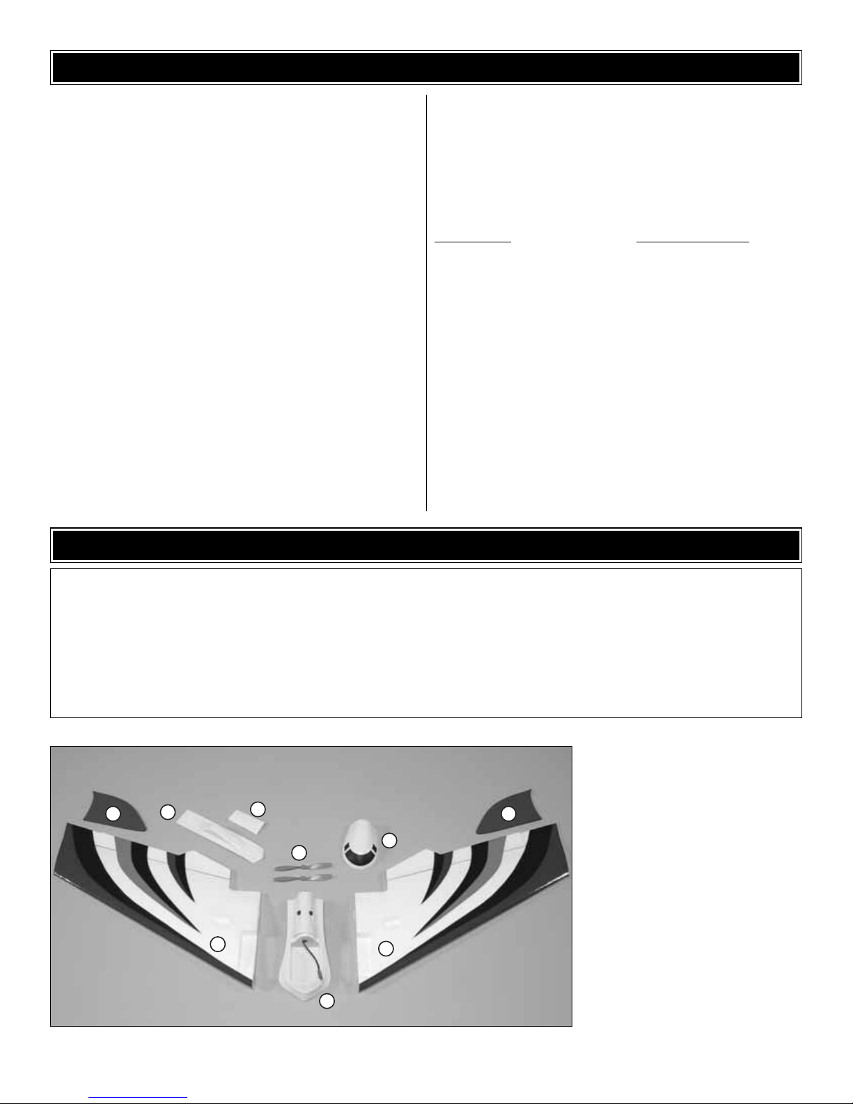
Kit Contents (Photographed)
1 Wing Halves (2)
2 Wing Tips (2)
3 Radio Tray
4 Radio Tray Hatch
5 Sling Handle
6 Hook and Loop Material
7 Propellers (2)
Kit Contents (Not Photographed)
3x225 mm [1/8" x 8-7/8"] Fore Carbon
Wing Joiner Rod (1)
3x500 mm [1/8" x 19-5/8"] Aft Carbon
Wing Joiner Rod (1)
Control Horns (2)
Control Horn Back Plates (2)
#2 x 5/16" [8 mm] Screws (4)
90° Pushrod Connectors (2)
64mm [2-1/2"] Pushrods (4)
25mm [1"] Heat-Shrink Tubing (2)
2 2
5
6
7
1
4
1
3
Page 5

❏ 1. Locate the channels in each wing half that contain the
servo wire draw strings.
❏ 2. Being careful not to sever the strings, cut away just
enough foam above these channels at the wing roots to
accommodate the thickness of the servo wires.
❏ 3.Cut off three arms from (2) four-arm servo horns, leaving
one of the long arms intact as shown.
❏ 4. Cut off the mounting tabs from the ser vo cases.
❏ 5. Temporarily connect the servos to your radio system.
Tur n the transmitter on and center your trim levers.With the
radio on, position the arms perpendicular to the servos.Make
a left and a right servo. If the ser vo model you are using has
the servo lead exiting from the side of the servo case as
shown in the picture above, use a hobby knife to remove
material from the servo bay in the wing until it fits properly.
❏ 6. Use the strings to pull the servo leads through the
wing panels.
❏ 7. Use epoxy to glue the servos into the servo bays. If you
would like the servos to be easily removable from the Mini
Slinger in the future, cover the servos in heat-shrink wrap
(TRIC6074) prior to gluing.You will then be able to cut the heatshrink to extract the servos from the wing with little damage.
Install the Servos
BUILDING INSTRUCTIONS
5
Page 6

❏ 1.Test fit the wing halves together with the carbon wing
joiner rods, with the long rod (500 mm [19-5/8"]) in the rear
and the short rod (225 mm [8-7/8"]) in the front. If the rods
prevent the wing halves from mating together, cut or sand
the rods as necessary until a good fit is achieved. When
satisfied, lightly coat one half of each rod with epoxy and
insert them into a wing half.With rubbing alcohol, wipe away
any excess epoxy that collects on the root of the wing half.
❏ 2. When the epoxy has cured, mix another batch and
coat the other ends of the carbon tubes and the roots of the
wing panels. Slide the panels together making sure the
servo leads exit on top of the wing and use tape to hold them
tight while the epoxy cures. Wipe away any excess epoxy
that squeezes out.
❏ 1. Measure 16 mm [5/8"] from the inside edge of each
elevon and make a mark as shown in the picture.
❏ 2. Cut a 6 mm [1/4"] slot 8 mm [5/16"] aft of the hinge line
for the control horns. Make the cuts so that the control
horns will be parallel with the servo arms.
❏ 3. Push the control horns through the cuts you made in
the elevons. Press a control horn backing plate onto the
underside of each control horn. Secure the backing plates
and control horns to the elevons with foam safe CA glue.
Connect the Control Linkages
Join the Wing Halves
6
Page 7

❏ 4. Locate the four 2-1/2" [64mm] pushrods and two 1"
[25mm] long pieces of heat shrink tubing. Using the 90°
pushrod connectors, attach a pushrod to the outer hole of
each servo horn and the middle hole of each control horn. If
necessary , use a 1/16" [1.6mm] drill bit to enlarge the holes.
Insert a piece of heat shrink tubing onto the two pushrods
attached to the servo horns.
❏ 5. Use tape to temporarily hold the elevons in the neutral
position. Overlap the pushrod ends and join them together
using the heat shrink tubing. Use a solder ing iron to shrink
the tubing around the pushrods by moving it quickly back
and forth across it (do not use a micro torch or heat gun to
shrink the tubing as this will melt the foam close to the
pushrods).With the elevons still in the neutral position, apply
a couple drops of CA glue to each end of the heat shrink
tubing to secure them in place.
❏ 1. Using rubbing alcohol, clean the area where the radio
tray will be installed. Feed the servo wires through the hole
in the hatch. Peel the paper backing from the tape on the
underside of the radio tray hatch and press it into position.Be
sure that the hatch is held securely in place by the tape.
❏ 2. Install the sling handle on the underside of the wing
in the same manner.
❏ 3. Drill a 1.6 mm [1/16"] hole at an angle through the
corner of the radio tray and out the bottom of the wing.
Install the Radio Equipment
7
Page 8

❏ 4. With a shar p hobby knife, cut a 3 mm [1/8"] deep slit
on the underside of the wing from this hole to the end of the
wing parallel with the leading edge.
❏ 5. Feed the receiver antenna through the hole and
embed it in the slit. Cover the slit with transparent tape.
❏ 1. Use (4) #2 x 5/16" [8 mm] screws to attach the wing tips
to the wing.
❏ 2. Press the propeller onto the motor shaft. The two
indentations at the center of the prop should face the model.
❏ 3. Use the included hook and loop material to secure the
battery pack, receiver, and ESC to the radio tray. You can
also use optional double-sided servo tape. If using an
auxiliary elevon mixer, place it into the tray at this time and
check control surface operation with your radio. Computer
radio systems equipped with an elevon function will not
require a separate mixer to be installed.
Finish the Model
8
Page 9

❏ 1.T urn on the transmitter and receiver and center the trims.
❏ 2.With the transmitter and receiver still on, check all of the
control surfaces to see if they are centered. If necessary , break
the CA bond on the heat shrink tubing, adjust the position of the
pushrods inside the tubing to center the control surfaces, and
re-glue the tubing to the pushrods.
❏ 3. Make certain that the control surfaces respond in the
correct direction as shown in the diagram. If any of the
controls respond in the wrong direction, use the servo
reversing in the transmitter to reverse the servos connected
to those controls. Be certain the control surfaces have
remained centered. Adjust if necessary.
Use a ruler to accurately measure and set the control throw
of each control surface as indicated in the chart that follows.
If your radio does not hav e dual rates, w e recommend setting
the throws at the low rate setting.
At this stage the model should be in ready-to-fly condition
with all of the systems in place.
❏ 1.Use a felt-tip pen or 3 mm [1/8"]-wide tape to accurately
mark the C.G.on the bottom of the wing as shown. The C.G.
is located 137 mm [5-3/8"] back from the leading edge of
the wing.
More than any other factor, the C.G. (balance point) can
have the greatest effect on how a model flies, and may
determine whether or not your first flight will be
successful. If you value this model and wish to enjoy it for
many flights, DO NOT OVERLOOK THIS IMPORTANT
PROCEDURE. A model that is not properly balanced will
be unstable and possibly unflyable.
Balance the Model (C.G.)
IMPORTANT: The Mini Slinger ARF has been extensively
flown and tested to arrive at the throws at which it flies
best. Flying your model at these throws will provide you
with the greatest chance for successful first flights.If, after
you have become accustomed to the way the Mini Slinger
ARF flies, you would like to change the throws to suit your
taste, that is fine. However, too much control throw could
make the model difficult to control, so remember, “more is
not always better.”
These are the recommended control surface throws:
High Rate Low Rate
ELEVON: 10 mm [3/8"] up 6 mm [1/4"] up
10 mm [3/8"] down 6 mm [1/4"] down
NOTE:The throws are measured at the outer edges of the
elevons.Use the elevator stick to check control throws.
Set the Control Throws
Check the Control Directions
GET THE MODEL READY TO FLY
9
ELEVONS MOVE UP
RIGHT ELEVON MOVES UP
LEFT ELEVON MOVES DOWN
FULL THROTTLE
Page 10

❏ 2.With all of the parts of the model installed (ready to fly),
place the model on a Great Planes CG Machine, or lift it at
the balance point you marked.
❏ 3. If the tail drops, the model is “tail heavy” and the battery
pack and/or receiver must be shifted f orward or weight must be
added to the nose to balance. If the nose drops, the model is
“nose heavy” and the batter y pack and/or receiver must be
shifted aft or weight must be added to the tail to balance. If
possible, relocate the battery pack and receiver to minimize or
eliminate any additional ballast required.If additional weight is
required, use Great Planes (GPMQ4485) “stick on”lead. Begin
by placing incrementally increasing amounts of weight on the
wings at the tips or in the radio tray until the model balances.
If you are adding weight at the tail, be sure that weight is added
evenly at each trailing edge of the wing halves to maintain
lateral balance. Once you have determined the amount of
weight required, it can be permanently attached.
❏ 4. IMPORTANT: If you found it necessary to add any
weight, recheck the C.G.after the weight has been installed.
❏ 1. With the wing level, lift the model by the leading edge
tip and motor shaft. Do this several times.
❏ 2. If one wing always drops when you lift the model, it
means that side is heavy. Balance the airplane by adding
weight to the other wing tip (an additional screw works well
for this).An airplane that has been laterally balanced will
track better in loops and other maneuvers.
No matter if you fly at an AMA sanctioned R/C club site or if you
fly somewhere on your own, you should always have your
name, address, telephone number and AMA number on or
inside your model.It is required at all AMA R/C club flying sites
and AMA sanctioned flying events. Fill out the identification tag
on page 11 and place it on or inside your model.
Follow the battery charging instructions that came with your
charger.Y ou should alw a ys charge y our tr ansmitter batteries
the night before you go flying, and at other times as
recommended by the radio manufacturer.
Ground check the operational range of your radio before the
first flight of the day. With the transmitter antenna collapsed
and the receiver and transmitter on, you should be able to
walk at least 30 meters [100 feet] away from the model and
still have control.Have an assistant stand by your model and,
while you work the controls, tell you what the control surf aces
are doing. Repeat this test with the motor running at
various speeds with an assistant holding the model, using
hand signals to show you what is happening. If the control
surfaces do not respond correctly, do not fly! Find and
correct the problem first.Look for loose servo connections or
broken wires, corroded wires on old servo connectors, poor
solder joints in your battery pack or a defective cell, or a
damaged receiver crystal from a previous crash.
Range Check
CAUTION: Unless the instructions that came with your
radio system state differently, the initial charge on new
transmitter batteries should be done for 15 hours using
the slow-charger that came with the radio system.This
will “condition” the batter ies so that the next charge may
be done using the fast-charger of your choice.If the initial
charge is done with a fast-charger the batteries may not
reach their full capacity and you may be flying with
batteries that are only partially charged.
Charge the Batteries
Identify Y our Model
PREFLIGHT
Balance the Model Laterally
This is where your model should balance for the first
flights. Later, you may wish to experiment by shifting the
C.G. up to 6 mm [1/4"] forward or 6 mm [1/4"] back to
change the flying characteristics. Moving the C.G. forward
may improve the smoothness and stability, but the model
may then require more speed for tak eoff and mak e it more
difficult to slow for landing.Moving the C.G.aft makes the
model more maneuverable, but could also cause it to
become too difficult to control. In any case, start at the
recommended balance point and do not at any time
balance the model outside the specified range.
10
Page 11

Read and abide by the following excerpts from the Academy
of Model Aeronautics Safety Code.For the complete Safety
Code refer to
Model Aviation
magazine, the AMA web site or
the Code that came with your AMA license.
1) I will not fly my model aircraft in sanctioned events, air
shows, or model flying demonstrations until it has been
proven to be airworthy by having been previously,
successfully flight tested.
2) I will not fly my model aircraft higher than approximately
400 feet within 3 miles of an airport without notifying the
airpor t operator. I will give right-of-way and avoid flying in
the proximity of full-scale aircraft. Where necessary, an
observer shall be utilized to supervise flying to avoid
having models fly in the proximity of full-scale aircraft.
3) Where established, I will abide by the safety rules for the
flying site I use, and I will not willfully and deliberately fly my
models in a careless, reckless and/or dangerous manner.
5) I will not fly my model unless it is identified with my name
and address or AMA number, on or in the model. Note:
This does not apply to models while being flown indoors.
7) I will not operate models with pyrotechnics (any device
that explodes, burns, or propels a projectile of any kind).
1) I will have completed a successful radio equipment ground
check before the first flight of a new or repaired model.
2) I will not fly my model aircraft in the presence of
spectators until I become a qualified flier, unless assisted
by an experienced helper.
3) At all flying sites a straight or curved line(s) must be
established in front of which all flying takes place with the
other side for spectators. Only personnel involved with
flying the aircraft are allowed at or in the front of the flight
line. Intentional flying behind the flight line is prohibited.
4) I will operate my model using only radio control
frequencies currently allowed by the Federal
Communications Commission.
5) I will not knowingly operate my model within three
miles of any pre-existing flying site except in
accordance with the frequency sharing agreement
listed [in the complete AMA Safety Code].
9) Under no circumstances may a pilot or other person
touch a powered model in flight.
❏ 1. Check the C.G. according to the measurements
provided in the manual.
❏ 2. Be certain the battery and receiver are securely
mounted in the fuse.
❏ 3. Balance your model laterally as explained in
the instructions.
❏ 4. Confir m that all controls operate in the correct direction
and the throws are set up according to the manual.
❏ 5. Be sure the propeller is securely pressed onto the
motor shaft.
❏ 6. Place your name, address, AMA number and
telephone number on or inside your model.
❏ 7. Cycle your battery pack (if necessary) and make sure
it is fully charged.
❏ 8. If you wish to photograph your model, do so before
your first flight.
❏ 9. Range check your radio when you get to the flying field.
During the last few moments of preparation your mind may
be elsewhere anticipating the excitement of the first flight.
Because of this, you may be more likely to overlook certain
checks and procedures that should be performed before the
model is flown.To help avoid this, a check list is provided to
make sure these important areas are not overlooked. Many
are covered in the instruction manual, so where appropriate,
refer to the manual for complete instructions. Be sure to
check the items off as they are completed.
CHECK LIST
Radio Control
General
AMA SAFETY CODE (
EXCERPTS
)
11
Page 12

IMPORTANT: If you are an inexperienced modeler we
strongly urge you to seek the assistance of a competent,
experienced R/C pilot to check your model for airworthiness
AND to teach you how to fly. No matter how stable or
“forgiving” the Mini Slinger is, attempting to learn to fly on
your own is dangerous and may result in destruction of y our
model or even injury to yourself and others.Therefore, find
an instructor and fly only under his or her guidance and
supervision until you have acquired the skills necessary for
safe and fully controlled operation of your model.
We recommend flying the Mini Slinger when the wind is no
greater than 16 kmph [10 mph]. Less-experienced flyers
should fly the Mini Slinger only in calm (less than one mile
per hour) conditions.Frequently, winds are calm in the early
morning and early evening. Often these are the most
enjoyable times to fly anyway!
Until you have the Mini Slinger properly trimmed for level
flight, we recommend having an assistant hand-launch the
model instead of launching it yourself.
Tur n on the transmitter and plug the battery into the speed
control. Turn on the receiver by following the instructions
that came with your speed control. Secure the radio tray
hatch in place.
IMPORTANT: Confirm that the transmitter operates the
controls properly by moving the sticks and watching the
surfaces respond.
When ready to launch, the assistant should hold the Mini
Slinger by the sling handle, with the model in front of him
and pointed into the wind. With the pilot
(that would be
you!)
standing behind the plane, fully advance the throttle to
start the motor. When the motor is at full power, the hand
launcher should gently push the plane into the air at a level
or slightly nose-up attitude. Be cer tain the model is being
launched into the wind and be immediately ready to make
corrections to keep the airplane flying straight, level and into
the wind.
When the model has gained adequate flying speed under
its own power, gently pull the elevator stick back until the
airplane star ts a gradual climb. Many beginners tend to pull
too hard causing the model to stall, so be gentle on the
elevator and don’t panic. If you do pull too hard and you
notice the model losing speed, release the elevator stick
and allow the model to regain airspeed.
Continue a gradual climb and establish a gentle turn (away
from yourself and others) until the airplane reaches an
altitude of 20 to 30 meters [75 to 100 feet].
The main purpose of the first few flights is to learn how the
model behaves and to adjust the trims for level flight. After
the model has climbed to a safe altitude, reduce the throttle
slightly to slow the model, yet maintain altitude. The Mini
Slinger should fly well and maintain adequate airspeed at
about 1/2 throttle.
Adjust the elevator trim so the model flies le vel at the throttle
setting you are using. Adjust the aileron trim to level the
wings. It may take a few minutes to get the trims adjusted,
but this should be your first priority once at a comfortable
altitude.Continue to fly around, executing turns and making
mental notes (or having your assistant take notes f or y ou) of
what additional adjustments or C.G. changes may be
required to fine tune the model so it flies the way you like.
Begin the landing approach by flying downwind at an
altitude of approximately 6 meters [20 feet]. When the
airplane is approximately 15 to 30 meters [50 to 100 feet]
past you, gradually reduce power and make the “final” 180degree turn into the wind aligning the airplane with the
runway or landing area. Do not dive the airplane, as it will
pick up too much speed. Instead, allow the airplane to
establish a gradual descent. Concentrate on keeping it
heading into the wind toward the runway. When the plane
reaches an altitude of about 3 feet [1 meter], gently apply a
little “up elevator” to level the plane, but be careful as too
much up elevator will cause it to stall.While holding a slight
amount of up elevator the airplane will slow and descend as
it loses flying speed, thus touching-down on the runway.
Until you are able to accurately judge how far the Mini Slinger
can glide, it may be helpful to reserve some battery power to
run the motor so the plane can be flown back to the runway.
Best of luck and happy flying!
Landing
Flight
Takeoff
FLYING
 Loading...