

Page 1
Great Planes®Model Manufacturing Co. guarantees this kit to
be free from defects in both material and workmanship at the date
of purchase. This warranty does not cover any component parts
damaged by use or modification.In no case shall Great Planes’
liability exceed the original cost of the purchased kit. Further,
Great Planes reserves the right to change or modify this warranty
without notice.
In that Great Planes has no control over the final assembly or
material used for final assembly, no liability shall be assumed nor
accepted for any damage resulting from the use by the user of the
final user-assembled product. By the act of using the userassembled product, the user accepts all resulting liability.
If the buyer is not prepared to accept the liability associated
with the use of this product, the buyer is advised to return
this kit immediately in new and unused condition to the place
of purchase.
To make a warranty claim, send
the defective part or item to
Hobby Services at this address.
Include a letter stating your name, return shipping address, as
much contact information as possible (daytime telephone number,
fax number , e-mail address), a detailed description of the problem
and a photocopy of the purchase receipt. Upon receipt of the
package the problem will be evaluated as quickly as possible.
READ THIS MANUAL BEFORE STARTING
CONSTRUCTION. IT CONTAINS IMPORTANT
INSTRUCTIONS AND WARNINGS CONCERNING
THE ASSEMBLY AND USE OF THIS MODEL.
GPMZ0294 for GPMA1320 V1.0Entire Contents © Copyright 2004
Champaign, Illinois
Telephone: (217) 398-8970 ext. 5
airsupport@greatplanes.com
INSTRUCTION MANUAL
WARRANTY
Wingspan: 63 in [1600mm]
Wing Area: 775 sq in [50 dm2]
Weight: 7.25 - 8.25 lb [3290 - 3740 g]
Wing Loading: 21.5 - 24.5 oz/sq ft [65 - 75 g/dm2]
Length: 56.5 in [1435mm]
Radio: 4-channel, 5 servos
Engine: .61cu in [10cc] two-stroke,
.91cu in [15cc] four-stroke
Hobby Services
3002 N. Apollo Dr. Suite 1
Champaign IL 61822
USA
Page 2

INTRODUCTION . . . . . . . . . . . . . . . . . . . . . . . . . . . . . . 2
IMAA . . . . . . . . . . . . . . . . . . . . . . . . . . . . . . . . . . . . . 2
Scale Competition . . . . . . . . . . . . . . . . . . . . . . . . . . . 2
SAFETY PRECAUTIONS . . . . . . . . . . . . . . . . . . . . . . . 3
HARDWARE AND ACCESSORIES . . . . . . . . . . . . . . . . 3
Radio Equipment . . . . . . . . . . . . . . . . . . . . . . . . . . . . 3
Engine Recommendations . . . . . . . . . . . . . . . . . . . . . 3
Additional Items Required . . . . . . . . . . . . . . . . . . . . . . 4
Optional Supplies and Tools . . . . . . . . . . . . . . . . . . . . 4
IMPORTANT BUILDING NOTES . . . . . . . . . . . . . . . . . . 4
KIT INSPECTION . . . . . . . . . . . . . . . . . . . . . . . . . . . . . 5
Ordering Replacement Parts. . . . . . . . . . . . . . . . . . . . 6
PREPARATIONS. . . . . . . . . . . . . . . . . . . . . . . . . . . . . . 7
BUILD THE WING . . . . . . . . . . . . . . . . . . . . . . . . . . . . . 7
Install the Ailerons . . . . . . . . . . . . . . . . . . . . . . . . . . . 7
Install the Aileron Servos and Pushrods . . . . . . . . . . . 8
Join the Wings . . . . . . . . . . . . . . . . . . . . . . . . . . . . . 10
BUILD THE FUSELAGE . . . . . . . . . . . . . . . . . . . . . . . 11
Install the Stab, Elevators and Rudder . . . . . . . . . . . 11
Install the Landing Gear and Wheel Pants . . . . . . . . . 12
Install the Engine, Fuel Tank and Throttle Ser vo . . . . 13
Install the Cowl. . . . . . . . . . . . . . . . . . . . . . . . . . . . . 15
Install the Radio System. . . . . . . . . . . . . . . . . . . . . . 17
FINAL TOUCHES . . . . . . . . . . . . . . . . . . . . . . . . . . . . 19
GET THE MODEL READY TO FLY . . . . . . . . . . . . . . . 20
Check the Control Directions . . . . . . . . . . . . . . . . . . 20
Set the Control Throws. . . . . . . . . . . . . . . . . . . . . . . 21
Balance the Model (C.G.) . . . . . . . . . . . . . . . . . . . . . 21
Balance the Model Laterally . . . . . . . . . . . . . . . . . . . 22
PREFLIGHT . . . . . . . . . . . . . . . . . . . . . . . . . . . . . . . . 22
Identify Your Model . . . . . . . . . . . . . . . . . . . . . . . . . . 22
Charge the Batteries. . . . . . . . . . . . . . . . . . . . . . . . . 22
Balance Propellers . . . . . . . . . . . . . . . . . . . . . . . . . . 22
Ground Check . . . . . . . . . . . . . . . . . . . . . . . . . . . . . 22
Range Check . . . . . . . . . . . . . . . . . . . . . . . . . . . . . . 22
ENGINE SAFETY PRECAUTIONS . . . . . . . . . . . . . . . 23
AMA SAFETY CODE . . . . . . . . . . . . . . . . . . . . . . . . . 23
CHECK LIST. . . . . . . . . . . . . . . . . . . . . . . . . . . . . . . . 24
FLYING . . . . . . . . . . . . . . . . . . . . . . . . . . . . . . . . . . . . 24
Takeoff . . . . . . . . . . . . . . . . . . . . . . . . . . . . . . . . . . . 25
Flight . . . . . . . . . . . . . . . . . . . . . . . . . . . . . . . . . . . . 25
Landing . . . . . . . . . . . . . . . . . . . . . . . . . . . . . . . . . . 25
The Great Planes
®
“Little Toni” ARF is a great flying
reproduction of the 1940’s racer. Not only does it have the
great looks but it is also a pleasure to fly.You will be amazed
at how fast it flies and yet slows to a crawl for landing.
For the latest technical updates or manual corrections to the
Little Toni visit the Great Planes web site at
www.greatplanes.com. Open the “Airplanes” link, then
select the Little Toni ARF. If there is new technical
information or changes to this model a “tech notice”box will
appear in the upper left corner of the page.
The Great Planes Little Toni is an excellent sport-scale
model and is eligible to fly in IMAA events. The IMAA
(International Miniature Aircraft Association) is an
organization that promotes non-competitive flying of giantscale models. If you plan to attend an IMAA event, obtain a
copy of the IMAA Safety Code by contacting the IMAA at
the address or telephone number below, or by logging on to
their web site at:
www.fly-imaa.org/imaa/sanction.html.
IMAA
205 S. Hilldale Road
Salina, KS 67401
(913) 823-5569
Though the Great Planes Little Toni is an ARF and may not have
the same level of detail as an “all-out” scratch-built competition
model, it is a scale model nonetheless and is therefore eligible to
compete in the
Fun Scale
class in AMA competition (we receive
many favorable reports of Great Planes ARF’s in scale
competition!).In Fun Scale, the “builder of the model”rule does not
apply. To receive the five points for scale documentation, the only
proof required that a full size aircraft of this type in this
paint/markings scheme did exist is a single sheet such as a kit box
cover from a plastic model, a photo , or a profile painting, etc.If the
photo is in black and white, other written documentation of color
must be provided.Contact the AMA for a rule book with full details.
If you would like photos of the full-size Little Toni for scale
documentation, or if you would like to study the photos to
add more scale details, photo packs are available from:
Bob’s Aircraft Documentation
3114 Y uk on Av e
Costa Mesa, CA 92626
Telephone: (714) 979-8058
Fax:(714) 979-7279
e-mail: www.bobsairdoc.com
Scale Competition
IMAA
INTRODUCTIONTABLE OF CONTENTS
2
Page 3
1.Your Little Toni should not be considered a toy, but rather
a sophisticated, working model that functions very much like
a full-size airplane. Because of its performance capabilities,
the Little Toni, if not assembled and operated correctly,
could possibly cause injury to yourself or spectators and
damage to property.
2.Y ou must assemble the model according to the instructions.
Do not alter or modify the model, as doing so may result in an
unsafe or unflyable model. In a few cases the instructions may
differ slightly from the photos. In those instances the written
instructions should be considered as correct.
3.You must take time to build straight, true and strong.
4. You must use an R/C radio system that is in first-class
condition, and a correctly sized engine and components
(fuel tank, wheels, etc.) throughout the building process.
5. You must correctly install all R/C and other components
so that the model operates correctly on the ground and in
the air.
6.You must check the operation of the model before every
flight to insure that all equipment is operating and that the
model has remained structurally sound. Be sure to check
clevises or other connectors often and replace them if they
show any signs of wear or fatigue.
7. If you are not already an experienced R/C pilot, you
should fly the model only with the help of a competent,
experienced R/C pilot.
8.While this kit has been flight tested to exceed normal use,
if the plane will be used for extremely high stress flying,
such as racing, the modeler is responsible for taking steps
to reinforce the high stress points.
Remember:Take your time and follow the instructions to
end up with a well-built model that is straight and true.
If you have not flown this type of model before, we
recommend that you get the assistance of an experienced
pilot in your R/C club for your first flights. If you’re not a
member of a club, your local hobby shop has information
about clubs in your area whose membership includes
experienced pilots.
In addition to joining an R/C club, we strongly recommend y ou
join the AMA (Academy of Model Aeronautics). AMA
membership is required to fly at AMA sanctioned clubs.There
are over 2,500 AMA chartered clubs across the country.
Among other benefits, the AMA provides insurance to its
members who fly at sanctioned sites and events. Additionally,
training programs and instructors are available at AMA club
sites to help you get started the right way. Contact the AMA at
the address or toll-free phone number below:
Academy of Model Aeronautics
5151 East Memorial Drive
Muncie, IN 47302-9252
Tele. (800) 435-9262
Fax (765) 741-0057
Or via the Internet at: http://www.modelaircraft.org
Four channel radio
Four 54 oz-in servos and one 30 oz-in servo.
Two 6" [150mm] servo extension (HCAM2701 for Futaba)
Y-harness (HCAM2751 for Futaba)
500 mAh battery or greater
We have installed both a two and a four stroke engine in our
prototypes.The two-stroke engine requires much of the cowl to
be cut away while the f our-strok e maintains most of the integrity
of the cowl.If a more “scale”look is desired, we recommend the
four-stroke engine option over the two-stroke.
.61cu in [10cc] two-stroke,
.91cu in [15cc] four-stroke
Engine Recommendations
Radio Equipment
HARDWARE AND ACCESSORIES
NOTE:We, as the kit manuf acturer , provide y ou with a top quality
kit and great instructions, but ultimately the quality of your
finished model depends on how you build it;therefore , we cannot
in any way guarantee the performance of your completed model,
and no representations are expressed or implied as to the
performance or safety of your completed model.
PRO TECT YOUR MODEL,Y OURSELF
& OTHERS...FOLLOW THESE
IMPORTANT SAFETY PRECAUTIONS
3
Page 4
4
The following is the list of hardware and accessories
required to finish the Little Toni.Order numbers are pro vided
in parentheses.
❏ R/C foam rubber (1/4" [6mm] - HCAQ1000, or 1/2"
[13mm] - HCAQ1050)
❏ William’s Brother’s #626 1/4-scale spor tsman pilot
(WBRQ2626)
❏ 1/2 oz. [15g] Thin Pro™CA (GPMR6001)
❏ 1 oz. [30g] Medium Pro CA+ (GPMR6008)
❏ Pro 30-minute epoxy (GPMR6047)
❏ Pro 6-minute epoxy (GPMR6045)
❏ Drill bits: 1/16" [1.6mm], 5/64" [2mm], 3/32" [2.4mm],
1/8" [3.2mm], 3/16" [4.8mm], 9/64" [3.6mm]
❏ 8-32 tap and drill set (GPMR8103)
❏ #1 Hobby knife (HCAR0105)
❏ #11 blades (5-pack, HCAR0211)
❏ Medium T-pins (100, HCAR5150)
❏ Top Flite®MonoKote®sealing iron (TOPR2100)
❏ CA applicator tips (HCAR3780)
❏ Propeller (as recommended by the engine
manufacturer)
Here is a list of optional tools mentioned in the manual that
will help you build the Little Toni.
❏ 2 oz. [57g] spray CA activator (GPMR6035)
❏ R/C-56 canopy glue (JOZR5007)
❏ CA debonder (GPMR6039)
❏ Epoxy brushes (6, GPMR8060)
❏ Mixing sticks (50, GPMR8055)
❏ Mixing cups (GPMR8056)
❏ 36" metal ruler (HCAR0475)
❏ Curved-tip canopy scissors for trimming plastic parts
(HCAR0667)
❏ Robart Super Stand II (ROBP1402)
❏ 18" x 24" [460 x 610mm] Builder’s Cutting Mat
(HCAR0455)
❏ Hobbico®Duster™can of compressed air (HCAR5500)
❏ Masking tape (TOPR8018)
❏ Threadlocker thread locking cement (GPMR6060)
❏ Denatured alcohol (for epoxy clean up)
❏ Switch & Charge Jack Mounting Set (GPMM1000)
❏ Rotary tool such as Dremel
®
❏ Rotary tool reinforced cut-off wheel (GPMR8200)
❏ Servo horn drill (HCAR0698)
❏ Dead Center™Engine Mount Hole Locator
(GPMR8130)
❏ AccuThrow™Deflection Gauge (GPMR2405)
❏ CG Machine™(GPMR2400)
❏ Precision Magnetic Prop Balancer™(TOPQ5700)
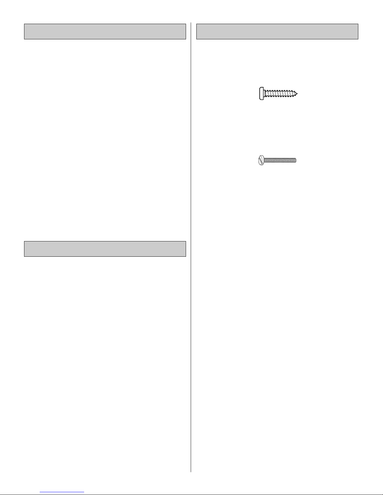
There are two types of screws used in this kit:
Sheet metal screwsare designated by a number and a length.
For example #6 x 3/4"
This is a number six screw that is 3/4" long.
Machine screws are designated by a number , threads per
inch, and a length.
For example 4-40 x 3/4"
This is a number four screw that is 3/4" long with forty
threads per inch
.
·
When you see the term
test fit
in the instructions, it
means that you should first position the part on the
assembly without using any glue, then slightly modify
or
custom fit
the part as necessar y for the best fit.
·
Whenever the term
glue
is written you should rely upon
your experience to decide what type of glue to use.When
a specific type of adhesive works best for that step, the
instructions will make a recommendation.
·
Whenever just
epoxy
is specified you may use
either
30minute (or 45-minute) epoxy or6-minute epoxy. When
30-minute epoxy is specified it is highly recommended
that you use only 30-minute (or 45-minute) epoxy,
because you will need the working time and/or the
additional strength.
·
Photos and sketches are placed before the step they
refer to. Frequently you can study photos in following
steps to get another view of the same parts.
·
The Little Toni ARF is factory-covered with Top Flite
®
MonoKote®film. Should repairs ever be required,
MonoKote can be patched with additional MonoKote
purchased separately. MonoKote is packaged in six-foot
rolls, but some hobby shops also sell it by the foot. If only
a small piece of MonoKote is needed for a minor patch,
perhaps a fellow modeler would give you some.
MonoKote is applied with a model airplane covering iron,
but in an emergency a regular iron could be used. A roll
of MonoKote includes full instructions for application.
Following are the colors used on this model and order
numbers for six foot rolls.
True Red (TOPQ0227)
(continued on page 6)
Important Building Notes
Optional Supplies and Tools
Additional Items Required
Page 5
5
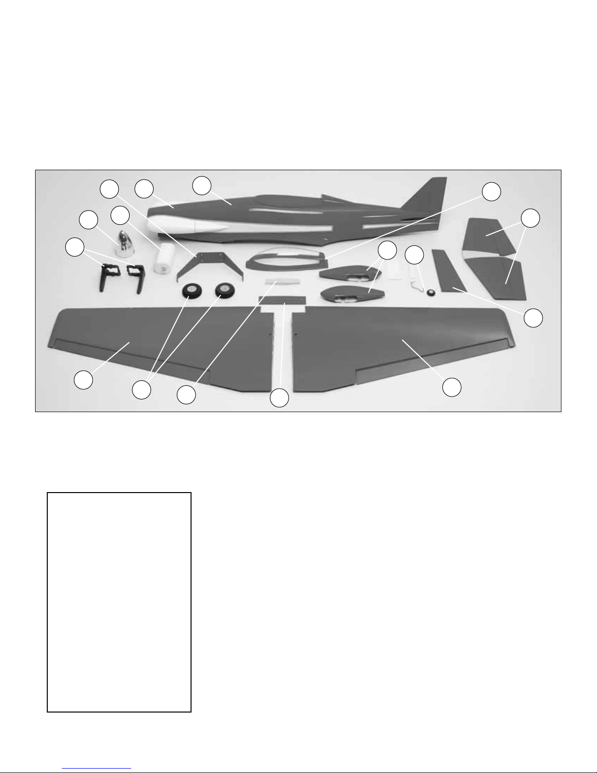
PARTS PHOTOGRAPHED
1. Canopy
2. Cowl
3. Fuselage
4. Engine Mount
5. Landing Gear
6.Wheel Pants
7.Wheels
8.Horizontal Stab & Elevators
9. Rudder
10. Fuel T ank
11. Spinner & Backplate
12.Tail Wheel Assembly
13. Left Wing & Aileron
14. Right Wing & Aileron
15.Wing Joiner
16.Wing Bolt Plate
Qty
5/32" x 2" Axle. . . . . . . . . . . . . . . . 2
Brass Body EZ Connector. . . . . . . 2
4-40 Blind Nuts . . . . . . . . . . . . . . . 4
4-40 nut . . . . . . . . . . . . . . . . . . . . 1
8-32 Blind Nut. . . . . . . . . . . . . . . . 8
5/16 - 24 Lock Nut . . . . . . . . . . . . 2
1/4-20 Blind Nuts. . . . . . . . . . . . . . 2
Large Nylon Control Horn . . . . . . . 5
Nylon Torque Rod Bearing. . . . . . . 1
1/4-20 Nylon Wing Bolt . . . . . . . . . 2
Nylon Clevis . . . . . . . . . . . . . . . . . 5
Nylon Retainer . . . . . . . . . . . . . . . 2
2" x 9" Hinge Material . . . . . . . . . . 1
FasLink. . . . . . . . . . . . . . . . . . . . . 4
Grey Plastic Outer Pushrod 24". . . 4
Silicone Clevis Retainer. . . . . . . . . 5
2-56 x 5/8" machine Screw. . . . . . 10
6-32 X 1/8" Set Screw . . . . . . . . . 2
6-32 x 1/4"SHCS. . . . . . . . . . . . . . 4
4-40 set screw. . . . . . . . . . . . . . . . 1
#2 x 3/8" Sheet Metal Screw. . . . . 12
Qty
#4 x 3/8" SMS. . . . . . . . . . . . . . . . 4
4-40 x 1/2" machine screw. . . . . . . 4
#2 x3/8" Wood Screw . . . . . . . . . . 4
8-32 x 1 1/4" SHCS. . . . . . . . . . . . 4
8-32 x 1" SHCS. . . . . . . . . . . . . . . 4
4-40 x 1/8" SHCS . . . . . . . . . . . . . 2
8-32 x 3/4" FH machine screw . . . . 4
3/32" Wheel Collar. . . . . . . . . . . . . 1
5/32" Wheel Collar. . . . . . . . . . . . . 6
1 1/4" tailwheel . . . . . . . . . . . . . . . 1
.074 wire Threaded 1 End 36". . . . 4
.074 x 6" Pushrod Wire . . . . . . . . . 2
4-40 x 12" thread wire . . . . . . . . . . 1
#4 Lock Washer . . . . . . . . . . . . . . 4
#4 flat washers . . . . . . . . . . . . . . . 8
#2 Flat Washers . . . . . . . . . . . . . . 12
#8 Lock Washers. . . . . . . . . . . . . . 8
#8 Flat Washers . . . . . . . . . . . . . . 8
Parts Layout
Before starting to build, take an inv entory of this kit to make
sure it is complete, and inspect the parts to make sure they
are of acceptable quality. If any parts are missing or are not
of acceptable quality, or if you need assistance with
assembly, contact Product Support. When reporting
defective or missing parts, use the part names exactly as
they are written in the Kit Contents list on this page.
Great Planes Product Support
3002 N Apollo Drive, Suite 1
Champaign, IL 61822
Telephone: (217) 398-8970, ext. 5
Fax: (217) 398-7721
E-mail: airsupport@greatplanes.com
13
15
16
9
6
4
5
10
11
12
1
2
3
8
7
14
PARTS NOT PHOTOGRAPHED
KIT INSPECTION
Page 6

(continued from page 4)
·
The stabilizer and wing incidences and engine thrust
angles have been factory-built into this model. However,
some technically-minded modelers may wish to check
these measurements anyway. To view this information
visit the web site at greatplanes.com and click on
“Technical Data.” Due to manufacturing tolerances, which
will have little or no effect on the way your model will fly,
please expect slight deviations between your model and
the published values.
IMPORTANT INFORMATION ABOUT
WORKING WITH FIBERGLASS
If you have never worked with fiberglass there are a few
basic things you should be aware of.
1. When cutting fiberglass, be sure you are cutting the
correct place. Unlike wood, you are not able to go back and
easily fix a mistake.
2.Whenever you are gluing a part to the inside of fiberglass it is
important to roughen the inside surface of the fiberglass with
220-grit sandpaper, then wipe the area with rubbing alcohol.
The molding process leaves a waxy residue that can prevent a
good bond between the glue and the parts being glued.
3.If you do not ha ve a high-speed motor tool such as a Dremel
™
tool you should consider purchasing one or borrowing one from
a fellow modeler .This, combined with a fiberglass cut-off wheel,
will be extremely helpful in the assembly process.
WARNING:The cowl, wheel pants and fuselage included in
this kit are made of fiberglass, the fibers of which may cause
eye, skin and respiratory tract irritation. Never blow into a
part to remove fiberglass dust, as the dust will blow back
into your eyes. Always wear safety goggles, a particle mask
and rubber gloves when grinding, drilling and sanding
fiberglass parts. Vacuum the parts and the work area
thoroughly after working with fiberglass parts.
Replacement parts for the Great Planes Little Toni ARF are
available using the order n umbers in the Replacement Parts List
that follows. The fastest, most economical service can be
provided by your hobby dealer or mail-order company. Parts
may also be ordered directly from Hobby Services, but full retail
prices and shipping and handling charges will apply. Illinois and
Nevada residents will also be charged sales tax.
To locate a hobby dealer, visit the Hobbico web site at
www.hob bico .com.Choose "Where to Buy" at the bottom of the
menu on the left side of the page. Follow the instructions
provided on the page to locate a U.S ., Canadian or International
dealer.If a hobby shop is not available, replacement parts may
also be ordered from Tower Hobbies at www .to werhobbies.com,
or by calling toll free (800) 637-6050, or from Hobby Services by
calling (217) 398-0007, or via facsimile at (217) 398-7721. If
ordering via fax, include a Visa or MasterCard number and
expiration date for payment.
Mail parts orders and payments by personal check to:
Hobby Services
3002 N Apollo Drive, Suite 1
Champaign IL 61822
Be certain to specify the order number exactly as listed in
the Replacement Parts List. Payment by credit card or
personal check only; no C.O.D.
If additional assistance is required for any reason, contact
the appropriate Product Support by e-mail or by telephone
at (217) 398-8970.
productsupport@greatplanes.com
Replacement Parts List
Or
der Number Description How to purchase
GPMA2400 . . . . . Wing Kit . . . . . . . . . .Hobby Supplier
GPMA2401 . . . . . Fuse Kit . . . . . . . . . .Hobby Supplier
GPMA2404 . . . . . Tail Set . . . . . . . . . .Hobby Supplier
GPMA2402 . . . . . Cowl . . . . . . . . . . . .Hobby Supplier
GPMA2405 . . . . . Canopy . . . . . . . . . .Hobby Supplier
GPMA2403 . . . . . Landing Gear . . . . . .Hobby Supplier
GPMA2406 . . . . . Wheel Pants . . . . . .Hobby Supplier
GPMA2407 . . . . . Spinner . . . . . . . . . .Hobby Supplier
GPMA2408 . . . . . Decal Sheet . . . . . . .Hobby Supplier
Missing pieces. . . . . Product Support
Instruction manual . . Product Suppor t
Full-size plans . . . . . Not available
Ordering Replacement Parts
1/64" = .4mm
1/32" = .8mm
1/16" = 1.6mm
3/32" = 2.4mm
1/8" = 3.2mm
5/32" = 4mm
3/16" = 4.8mm
1/4" = 6.4mm
3/8" = 9.5mm
1/2" = 12.7mm
5/8" = 15.9mm
3/4" = 19mm
1" = 25.4mm
2" = 50.8mm
3" = 76.2mm
6" = 152.4mm
12" = 304.8mm
15" = 381mm
18" = 457.2mm
21" = 533.4mm
24" = 609.6mm
30" = 762mm
36" = 914.4mm
1" = 25.4mm (conversion factor)
Metric Conversions
6
Page 7
❏ 1. If you have not done so already, remove the major
parts of the kit from the box and inspect for damage. If any
parts are damaged or missing, contact Product Suppor t at
the address or telephone number listed in the “Kit
Inspection” section on page 5.
❏ 2. Carefully remove the tape and separate the ailerons
from the wing and the elevators from the stab. Use a
covering iron with a covering sock on high heat to tighten
the covering if necessary. Apply pressure over sheeted
areas to thoroughly bond the covering to the wood.
Do the right wing first so your work matches the
photos the first time through.You can do one wing at a
time, or work on them together.
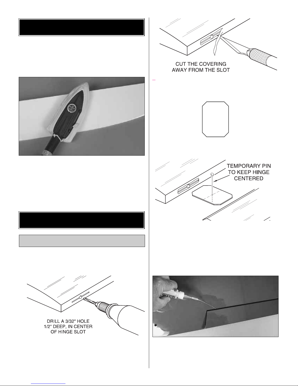
❏❏1. Dr ill a 3/32" [2.4mm] hole, 1/2" [13mm] deep in the
center of each hinge slot to allow the CA to “wick”in. Followup with a #11 blade to clean out the slots.
Hint: If you have one, use a high-speed rotary tool to drill
the holes.
❏❏2.Use a sharp #11 blade to cut a strip of covering from
the hinge slots in the wing and aileron.
❏❏3. Cut five 3/4" x 1" [19 x 25mm] hinges from the CA
hinge strip. Snip off the cor ners so they go in easier.
❏❏4. Test fit the ailerons to the wing with the hinges. If
the hinges don’t remain centered, stick a pin through the
middle of the hinge to hold it in position.
❏❏5. Remove any pins you may have inserted into the
hinges. Adjust the aileron so there is a small gap between the
LE of the aileron and the wing. The gap should be small, just
enough to see light through or to slip a piece of paper through.
❏❏6. Apply six drops of thin CA to the top and bottom of
each hinge. Do not use CA accelerator. After the CA has
fully cured, test the hinges by pulling on the aileron.
❏ 7. Repeat steps 1- 6 for the left wing panel.
Install the Ailerons
BUILD THE WING
PREPARATIONS
7
Page 8
❏❏1. Installing the ser vos in the wing will require the use
of one 6" [152mm] servo extension for each aileron. One
Y-harness connector is required and is used to allow the
aileron servos to plug into one slot in your receiver.You may
have a computer radio that allows you to plug the servos
into separate slots and mix them together through the radio
transmitter. If you choose to mix them with the radio rather
than the Y-harness, refer to the instructions with your
particular brand of radio.
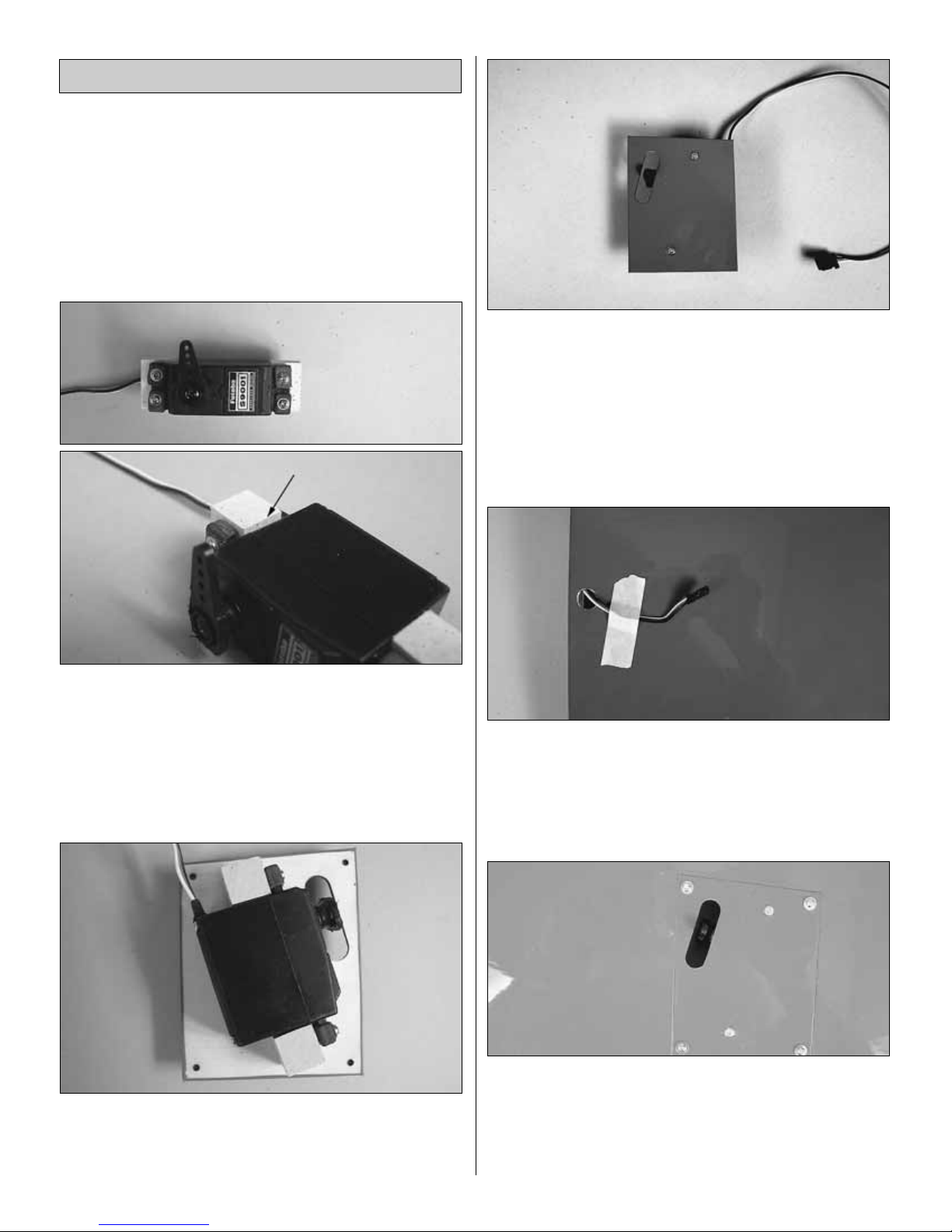
❏❏2. Remove the tape holding the servo cover to the
fuselage. Locate two 1/2" x 1/2" x 3/4" [13 x13 x 19mm]
hardwood blocks.Place the blocks against the sides of your
aileron servo. When positioning the blocks they should be
slightly higher than the servo case. Drill a 1/16" [1.6mm]
hole through the blocks for the servo screws. Using the
hardware included with your radio system, screw the servos
to the two blocks.
❏❏3. Apply 6-minute epoxy to each block. Position the
blocks so that the servo arm is centered over the opening in
the cover. Clamp the blocks to the cover .When the glue has
cured remove the clamps.
❏❏4. Mark the center of the hardwood blocks on the
cover. Drill a 1/16" [1.6mm] hole through the marks, drilling
through the blocks. Install a #2 x 3/8" [9mm] wood screw
into each of the holes tightening them against the cover.
❏❏5. Attach the servo extension to the aileron servo.
Secure the connectors together using a large piece of heat
shrink tubing, tape or other method.
❏❏6. Located in the wing in the ser vo compar tment, a
string is taped to the wing skin. Tie the string to the end of
the servo wire.Pull the servo wire through the wing with the
string.Feed the servo wire out the hole in the top of the wing
center section.Tape the servo wire to the wing to prevent it
from falling back into the wing.
❏❏7. Center the servo and install a ser vo arm as shown.
Test fit the servo cover into the wing.Depending on the size
and mounting position of your particular servo you may
need to trim away some of the wood edge the cover rests
on.T rim as needed to allow the servo cov er to be positioned
properly in the wing.
Install the Aileron Servos & Pushrods
8
Page 9
❏❏8. Place the cover in place on the wing. Drill a 1/16"
[1.6mm] hole through each of the pre-drilled mounting
holes. Remove the cover from the wing. Install and remove
a #2 x 3/8" [9mm] sheet metal screw into each of the four
holes. Inser t a drop of thin CA into the holes to harden the
wood.After the clue has cured, install the cover with four #2
x 3/8" [9mm] sheet metal screws and four #2 flat washers.
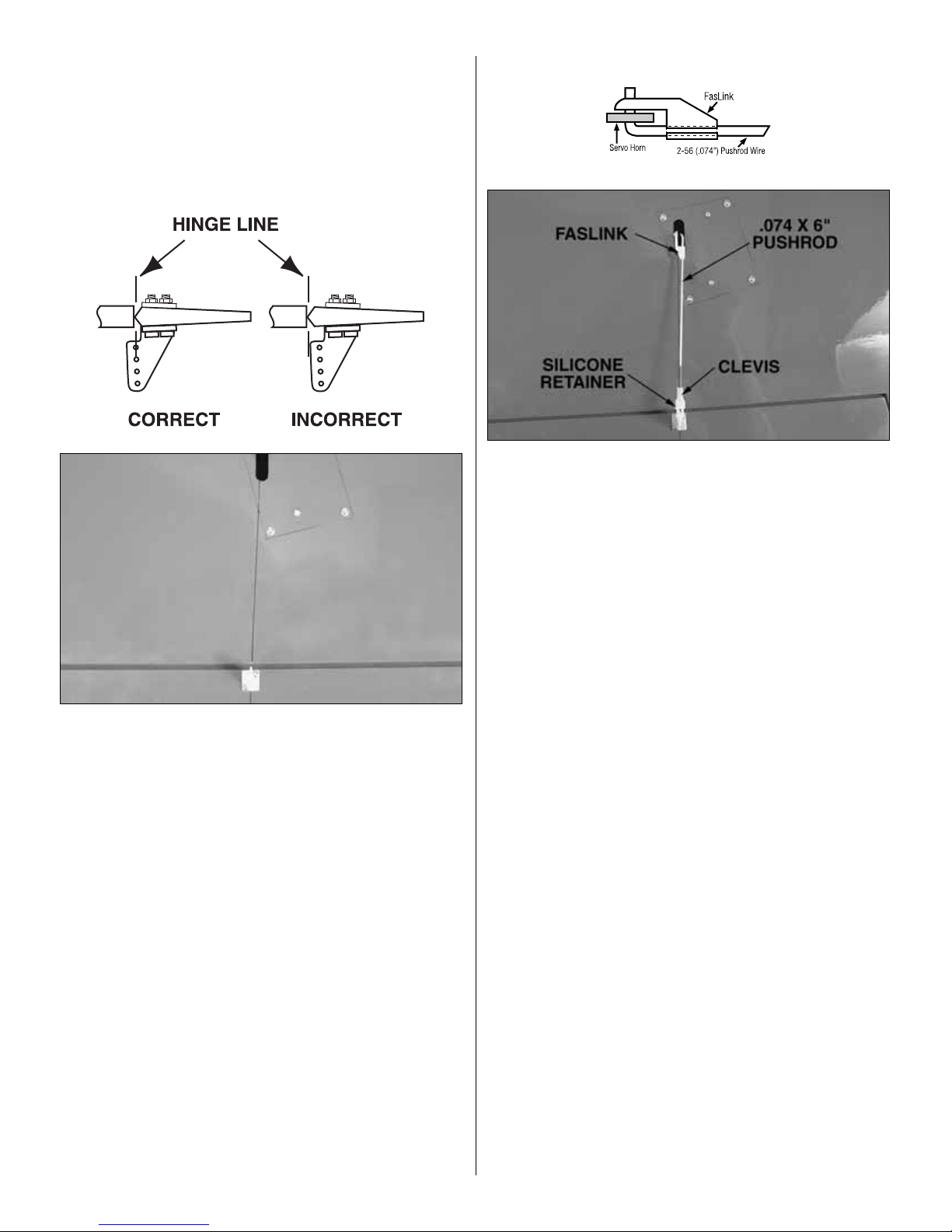
❏❏9. Position a large nylon control horn on the aileron,
positioning it as shown in the sketch and aligning it with the
servo. Mark the location for the screw holes. Drill through
the marks you made with a 1/16" [1.6mm] drill bit, drilling
through the aileron. Secure the control horn to the aileron
with two 2-56 x 5/8" [16mm] machine screws and the nylon
mounting plate.
❏❏10. Locate a .074" x 6" [.074" x 152mm] pushrod wire
threaded on one end. Screw a nylon clevis onto the
threaded end of the wire 20 full turns.Install a silicone clevis
keeper onto the clevis, then install the clevis in the second
hole from the end of the aileron control horn.
❏❏11. Be sure the aileron ser vo is centered. Enlarge the
first hole in the servo arm with a Hobbico Servo Horn Drill
(or a #48 or 5/64" [2mm] drill bit). Center the aileron and
align the wire pushrod with the hole in the end of the servo
arm. Using a marker, mark the location where the wire
aligns with the hole in the servo arm. On that mark make a
90 degree bend. From the bend measure an additional
3/16" [4.8mm] then cut off the excess pushrod wire.
❏❏12. Install the wire into the hole in the servo arm using
a nylon FasLink as shown in the sketch.
❏ 13. Repeat steps 1-12 for the left wing panel
9
Page 10

❏1. Locate the hardwood wing joiner.Notice that the joiner
is cut with a double taper. Test fit the joiner into both wing
halves to see exactly how it fits into the wing, making sure
that it is not too tight. Sand the joiner as needed to get a
good fit.
❏ 2. Apply 30-minute epoxy to all sides of the wing joiner,
the joiner pocket in both wing panels and the root rib of
each wing panel. Push the wing panels together and hold
them in place with masking tape. Before the glue cures, set
the wing flat on your bench and measure the dihedral.The
distance from the top of the bench to the center of the wing
as measured at the wing tip should be approximately 6"
[152mm]. Block the wingtip up while the glue cures.
Note:
Due to production techniques there may be some variance
in the actual dihedral of each model. Our prototypes flew
well with the dihedral anywhere between 5-3/4" and 6-1/2"
[146mm and 165mm].
❏ 3. Set the wing aside allowing the glue to cure.
❏ 4. Place the plywood wing bolt mounting plate in
position on the bottom of the wing, over the wing bolt holes.
Using a fine tip marker, trace the outline of the plate onto
the wing. Use a sharp #11 hobby knife or use the Expert
Tip that follows to cut the covering from the wing along the
lines you have marked. Use care to cut only into the
covering and not into the wood.
❏ 5. Glue the plywood wing bolt plate to the wing.
❏ 6. Fit the wing to the fuselage with two 1/4 - 20 nylon
wing bolts.
Use a soldering iron to cut the covering from the stab.The
tip of the soldering iron doesn't have to be sharp, but a fine
tip does work best. Allow the iron to heat fully. Use a
straightedge to guide the soldering iron at a rate that will
just melt the covering and not burn into the wood. The
hotter the soldering iron, the faster it must travel to melt a
fine cut. Peel off the covering.
HOW TO CUT COVERING FROM BALSA
Join the Wings
10
Page 11

❏ 1. Test fit the stab into the opening in the back of the
fuselage. Stand back and look at the stab in relation to the
wing.The stab should be parallel with the wing.If not, sand
the stab saddle until the stab and wing are aligned.
❏2. Measure the distance from the tip of the stab to the tip of
each wing. Adjust the position of the stab until both are equal.
❏3. Mark the sides of the fuselage onto the top and bottom
of the stab with a fine tip marker. Cut the covering away
from the center of the stab using the same method used on
the wing. Reinsert the stab into the fuselage, double
checking the alignment with the wing.
❏ 4. When satisfied with the fit of the stab, use thin CA with
a CA applicator tip to wick glue into the stab saddle. Apply
the glue to the top, bottom and both sides of the fuselage.
Allow the glue to fully cure before moving.After the glue has
cured remove the wing from the fuselage.
Hint: Do not use any accelerator.This will most likely cause
the glue to get a white haze on the fuselage and stab.Allow
the plane to sit for approximately 5 minutes until the glue is
completely cured.
❏ 5. Cut six hinges (three for each elevator half) from the
hinge material. Install the two elevator halves using the
same method used for the ailerons. Once you are satisfied
with the positioning of the elevators , glue them in place with
thin CA the same as was done on the ailerons.
❏ 6. Locate the tail wheel wire. Test fit the nylon bushing
into the slot at the bottom of the rudder post. Make any
needed adjustments to the slot to get a good fit. Apply a
couple of drops of oil to the wire where it passes through the
nylon bushing to prevent glue from getting into the bushing.
Apply epoxy to both sides of the nylon bushing and insert it
into the slot. Allow the glue to cure.
❏ 7. Cut three more hinges and insert them into the rudder
using the same technique you used on the elev ators.Before
installing the rudder to the fin, apply a small amount of
epoxy into the hole that is drilled in the bottom of the rudder.
Quickly move to the next step.
Install the Stab, Elevators & Rudder
BUILD THE FUSELAGE
11
Page 12

❏ 8. Insert the rudder onto the fin, installing the hinges into
the fin and inserting the tail wheel wire into the hole you
applied the epoxy in.Position the rudder and then apply thin
CA onto the hinges.
This completes the installation of the tail surfaces.You will
finish the installation of the control horns and pushrods
when you perform the radio installation.
❏❏1. Bolt the landing gear to the fuselage with four 8-32
x 3/4" [19mm] flat head machine screws. Apply a drop of
thread lock to the threads before screwing them into the
fuselage. When installing the gear, the taper should be to
the back of the fuselage.
❏❏2. Cut both axles to a length of 1-3/8" [35mm]. A high
speed rotary tool with a cut-off wheel works well for
this application.
❏❏3. File a flat spot on the end of the axle. A high speed
rotary tool works well for this also.
❏❏4. Inser t a 6-32 set screw into a 5/32" [4mm] wheel
collar. Slide it onto the axle. Slide the wheel onto the axle
and then slide on another 5/32" wheel collar. Screw a 6-32
x1/4" [6mm] socket head cap screw into the wheel collar
with a drop of threadlocker. Center the wheel, then tighten
the set screws on the wheel collars.
❏❏5. Slide the wheel pant over the wheel. Attach the
wheel pant to the landing gear with two 4-40 x 1/2" [13mm]
machine screws, #4 flat washers and #4 lock washers.
Apply a drop of threadlocker to each screw.
❏ 6. Repeat step 1-5 for the other wheel pant.
Install the Landing Gear
and Wheel Pants
12
Page 13

❏ 7. Install the tail wheel onto the tail wheel wire. Lock it in
place with a 3/32" [2.4mm] wheel collar and a 4-40 set
screw with a drop of threadlocker.
❏1.Use a fine-point felt-tip pen to extend the crossing lines
on the firewall. Cut out the engine mounting pattern on
page 27 of this manual. Tape it on the firewall aligning the
lines on the pattern with the lines on the firewall.
❏ 2. Use a 3/16" [4.8mm] bit to drill through the firewall at
the marks on the engine mounting pattern.
❏ 3. Install four 8-32 blind nuts into the backside of the
firewall. We have included a 4-40 x 12" [305mm] rod
threaded on one end to assist you with this process.Screw
a 4-40 nut onto the threaded end of the rod.Slide a blind nut
(flat side of the blind nut toward the nut) onto the rod. Insert
the wire through the inside of the fuselage, through one of
the holes you drilled in the firewall.Pull on the wire until the
blind nut pulls into the firewall. Remove the wire. Carefully
screw an 8-32 x 1" [25mm] socket head cap scre w with a #8
flat washer into the blind nut. Tighten the bolt and washer
against the firewall until the blind nut is pulled firmly against
the firewall.Remove the socket head cap screw. Repeat this
procedure for the remaining three blind nuts.
❏ 4. Install the engine mount to the firewall using four each
8-32 x 1-1/4" [32mm] socket head cap screws, #8 flat
washers and #8 lock washers. When installing the mount,
use your engine to determine the spacing needed for the
mounting rails.
The following engine mounting instructions apply to both the
two-stroke and four-stroke engines. As mentioned earlier in
the instructions, the four-stroke engine lea v es much more of
the cowl intact than will the two-stroke.We have included a
picture of a two-stroke installation that is most likely the
“worst case scenario” because of the very large muffler.You
will notice that to install this muffler we had to cut away a
portion of the firewall. We did test fly the plane in this
configuration and have determined it does not affect the
structural integrity. Should you have to cut a portion of the
fuselage/ firewall to clear your muffler, you may need to
insert an additional hardwood block (not included) inside of
the fuselage for mounting the cowl. You may also wish to
build a box inside of the fuselage to prevent fuel residue
from getting inside the fuselage.
Install the Engine, Fuel Tank
and Throttle Servo
13
Page 14

❏5. Position the engine in the mount so the distance from the
front of the firewall to the front of the thrust washer measures
5-5/16" [135mm].Mark the location of the engine on the mount.
The Great Planes Dead Center Hole Locator (GPMR8130)
works well for this. Drill through the marks you have made on
the engine mount with a #29 or 9/64" [3.6mm] drill bit.Tap each
of the holes with an 8-32 tap.
6.Install the engine onto the mount with four each, 8-32 x 1"
[25mm] socket head cap screws, #8 flat washers and # 8
lock washers.
❏ 7. Mark the location on the firewall where the throttle
pushrod will pass through. Drill a 3/16" hole on that mark.
Locate the 24" [610mm] gray plastic pushrod tube.Cut it to
a length of 16". Roughen one end of the tube with 220-gr it
sandpaper. Install the un-sanded end of the pushrod tube
into the front of the firewall through the hole you drilled in
the firewall and through the hole inside the fuselage, in the
fuselage former. Apply CA to the roughened end of the
plastic tube, gluing it into the firewall.
❏ 8. Locate a .074 x 36" [914mm] pushrod wire. Cut it to a
length of 21" [533mm], cutting off the threaded end of the
wire.Insert this wire into the plastic tube you installed for the
throttle.Install a brass screw lock connector into the throttle
arm, locking it to the arm with the nylon retainer. Insert this
wire into the screw lock connector and the plastic tube you
installed for the throttle.Lock the wire to the connector with
a 6-32 x 1/4" [6mm] socket head cap screw.
Refer to this photograph for steps 8 -12.
❏8.Locate two 3/8" x 3/8" x 3/8" [9 x 9 x 9mm] balsa blocks and
two plywood pushrod supports. Slide the supports over the
gray plastic throttle pushrod y ou have installed in the fuselage.
RETAINER
14
Page 15

❏ 10. Install the throttle ser vo into the tray in the fuselage.
Drill a 1/16" [1.6mm] hole through each of the mounting
holes in the servo.Install and then remove a servo mounting
screw into each of the holes you have drilled. Apply a
couple of drops of thin CA into the holes to harden the
threads. After the glue has cured, install your servo.
❏11.Install a brass-screw loc k connector and nylon retainer to
the servo arm. Slide it onto the pushrod wire, center the servo
and install the servo arm onto the servo.Then install the servo
screw into the servo and a 6-32 x 1/4" [6mm] socket head cap
screw into the screw-lock connector.
❏ 12. Cut the forward plywood pushrod support to fit
between the pushrod and the fuselage. Glue the two balsa
blocks to both sides of the support. Lightly sand the
fuselage where the support will be glued and then wipe the
area with rubbing alcohol. Glue the forward support to the
fuselage side and glue the rear support to the ser vo tray.
❏ 13. Assemble the fuel tank as shown. Included with the
fuel tank hardware is a 24" length of fuel tubing.This will be
used for attaching the tank to the carburetor and muffler
pressure tap. If you will be using a fuel valve (not included)
for filling the tank rather than filling the tank by remo ving the
line from the carburetor , install it in the fuel line f ollo wing the
instructions included with the valve.
❏14. Install the fuel line included with the kit onto the tubes
extending from the fuel tank. Insert the lines and the fuel
tank into the fuselage. Hold the tank in place with a couple
of #64 rubber bands. Attach the carburetor line to the
carburetor. The vent line can be attached later when the
muffler is permanently installed.
❏ 1. Use card stock as a template for making the cut out in
the cowl.Tape the card stock to the fuselage behind where
the cowl will be mounted. Mark the card stock where the
engine extends outside of the cowl.Cut that area out of the
card stock.
❏2.Remove the engine from the mount;slide the cowl onto the
fuselage. (If you are installing the O.S. .91 four stroke engine,
you can remove the rocker ar m cover and the cowl will fit over
the engine without removing it.) Tape the cowl to the fuselage.
Trace the pattern from the card stock onto the cowling.
❏ 3. Remove the cowl from the fuselage. Cut out the area
you have marked. A high speed rotary tool wor ks well for
this.T ry to cut as closely to the area outlined as you can.Y ou
will be making adjustments to the cut out as you continue
with the installation of the cowl. The goal now is to just be
able to slip the cowl over the engine and onto the fuselage.
❏ 4. Reinstall the engine onto the engine mount. Slide the
cowl over the engine and onto the fuselage.
Install the Cowl
15
Page 16

❏5. Locate the five 1/8" [3mm] balsa disks shown.Glue the
three smaller disks to each other forming a 3/8" [9mm] thick
disk. The inside diameter of these disks is designed to fit
over the thrust washer of the O. S. .91 two-stroke engine
and the O.S. .91 four-stroke engine. Depending on the
engine you are installing, you may have to slightly enlarge
the inside diameter of the rings. If necessar y, enlarge the
disks just enough to fit snugly over the engine thrust
washer.Once the disk fits, glue the 3/8" [9mm] disk onto the
large disk inside the location marks on the disk.
❏6. Glue the remaining disk on the bottom of the large disk
as shown. This will become a handy aid in helping you to
properly center the cowl and the engine. In the future this
will be referred to as the cowl tool.
❏7. Look into the front of the fuselage and you will see four
cowl mounting blocks glued inside.The photo shows where
the blocks are located. Locate these blocks, so when you
mount the cowl you drill into the blocks.The easiest way to
find and mark the location of the blocks is to shine a highpowered flash light inside the fuselage.You should be able
to see the shadowed outline of the blocks outside of the
fuselage. Mark the location of the blocks with a felt-tip pen.
This can be cleaned off later with rubbing alcohol.
❏8.Place masking tape on the fuselage extending ov er the
location of the blocks. Draw a 1-1/2" [40mm] line from the
center of the block back.Do this at all four blocks.
❏9.Install the cowl onto the front of the fuselage.Slide the cowl
tool in place over the crankshaft of the engine and into the
opening in the front of the cowl. Hold it tight against the engine
by tightening the prop nut and washer against the cowl tool.
16
Page 17

❏10. Make any adjustment needed to align the paint lines on
the cowl with the fuselage. At each of the reference lines you
have dra wn on the fuselage, measure from the fuselage back to
the cowl 1-1/2" [38mm].Mark that location on the cowl.
❏11. Drill a 3/32" [2.4mm] hole through the cowl and fuselage
mounting blocks at one of the four locations.Tempor arily screw
a #4 x 3/8" [9mm] sheet metal screw and a #4 flat washer into
the cowl and fuselage. Drill a hole at another location. Install
another screw and washer. Do this for all four mounting blocks.
❏ 12. Remove the cowl.Apply a couple of drops of thin CA
to the holes to harden the threads.After the glue has cured,
install the cowl with the #4 x 3/8" [9mm] sheet metal screws
and #4 flat washers.
❏ 13. Using a technique similar to the way you located and
cut the cowl for the engine cylinder head, make any
additional cut outs needed in the cowl for the needle valve,
muffler, glow plug, etc.
❏ 1. Locate three .074" x 36" [.074" x 914mm] pushrod
wires threaded on one end. Screw a nylon clevis onto the
threaded end of the wires 20 full turns. Install a silicone
clevis keeper onto the clevises.
❏ 2. Slide two of the wires with clevises attached into the
openings closest to the back of the fuselage on both sides
of the fuselage.
❏ 3. Connect a nylon control horn onto each of the two
clevises. Position the control horn on the elevators,
positioning it the same way as you did with the ailerons.
Mark the location for the screw holes. Drill through the
marks you made with a 1/16" [1.6mm] drill bit, drilling
through the elevator. Secure the control horn to the elevator
with two 2-56 x 5/8" [16mm] machine screws and the nylon
mounting plate.
❏4. Connect the third rod into the remaining opening in the
fuselage. Connect the control hor n to the clevis and attach
the control horn to the rudder in the same way you installed
them to the elevators.
Install the Radio System
17
Page 18

❏ 5. Install the rudder servo into the ser vo tray at the position
shown.Mark the location for the servo mounting screws.Drill a
1/16" [1.6mm] hole through the marks, drilling through the
plywood tray.Insert and then remove one of the servo mounting
screws supplied with your radio into each of the four holes you
have drilled. Apply a couple of drops of thin CA to each of the
holes to harden the threads. After the glue has cured
permanently mount the servo.
❏ 6. Be sure the rudder servo is centered. Enlarge the
outermost hole in the servo arm with a Hobbico Servo Horn
Drill (or a #48 or 5/64" [2mm] drill bit). Center the rudder and
align the wire pushrod with the hole in the end of the servo
arm. Use a fine-point felt-tip pen to mark the wire where it
crosses the holes in the servo arm. On that mark make a 90
degree bend. From the bend measure an additional 3/16"
[4.8mm]. Then cut off the excess pushrod wire. Install a
nylon Faslink to the wire and servo arm.
❏ 7. Install the elevator servo into the servo tray. Position it
in line with the elevator pushrods .Mount the servo using the
same procedure used for the rudder servo.
❏ 8. Make a bend in one of the elevator pushrod wires
as shown.
❏9. Screw a 6-32 x 1/4" [6mm] socket head cap screw with
a small amount of threadlocker into two 5/32" [4mm] wheel
collars. Slide the wheel collars onto the wires. Align the
elevators.Tighten the set screws against the wires.Cut the
excess wire.
❏ 10. Be sure the elevator servo is centered. Enlarge the
first hole in the servo arm with a Hobbico Servo Horn Drill
(or a #48 or 5/64" [2mm] drill bit). Center the elevators and
align the wire pushrod with the hole in the end of the servo
arm. Using a marker, mark the location where the wire
aligns with the hole in the servo arm. On that mark make a
90 degree bend. From the bend measure an additional
3/16" [4.8mm] and then cut off the excess pushrod wire.
Install a nylon Faslink to the wire and servo arm.
18
Page 19

❏ 11. Install the batter y and receiver as shown. Place 1/4"
thick foam under the receiv er and battery, holding it in place
with the Velcro®material included with the kit.
❏ 12. Use an arm cut from a servo horn to make an
antenna strain relief as shown. Inser t the receiver antenna
into the white antenna tube. Hold it to the fuselage by
placing a small rubber band around the tail wheel and the
end of the antenna.
❏ 1.We installed a ¼ scale Williams Brothers “Sportsman”
pilot (WBRQ2626).Because the Little Toni was such a small
racer, the head of the pilot is all that is required.To fit the
head you will have to sand a small portion of the chin from
the pilot figure.
❏ 2. Trim the canopy on the molded cut lines. The canopy
can be glued to the fuselage or screwed in place.If you look
inside the fuselage you will see four plywood mounting
blocks pre-installed for this purpose. Drill 1/16" [1.6mm]
holes into the cowl and the blocks .Hold the canopy in place
with four #2 x 3/8" [10mm] screws and four flat washers. If
you choose to glue the canopy in place, RC 56 canopy glue
works well for this application.
❏3. Install the propeller that is best suited to your engine.The
included spinner utilizes a frame that secures the spinner to the
back plate, eliminating the need for a special nut for the engine
crankshaft. Secure the back plate and the prop with the prop
nuts that came with your engine. Hold the spinner to the back
plate with the 4mm socket head cap screw.
FINAL TOUCHES
19
Page 20

1. Use scissors or a sharp hobby knife to cut the decals
from the sheet.
2. Be certain the model is clean and free from oily
fingerprints and dust. Prepare a dishpan or small bucket
with a mixture of liquid dish soap and warm water—about
one teaspoon of soap per gallon of water. Submerse the
decal in the soap and water and peel off the paper backing.
Note: Even though the decals have a “sticky-back” and are
not the water transfer type, submersing them in soap &
water allows accurate positioning and reduces air bubbles
underneath the decal.
3.P osition decal on the model where desired.Holding the decal
down, use a paper towel to wipe away most of the water.
4. Use a piece of soft balsa or something similar to
squeegee remaining water from under the decal. Apply the
rest of the decals the same way.
1.Turn on the transmitter and receiver and center the trims.
If necessary, remove the servo arms from the servos and
reposition them so they are centered. Reinstall the screws
that hold on the servo arms.
2.With the transmitter and receiv er still on, check all the control
surfaces to see if they are centered. If necessary, adjust the
clevises on the pushrods to center the control surfaces.
❏3. Make certain that the control surfaces and the carburetor
respond in the correct direction as shown in the diagram.If any
of the controls respond in the wrong direction, use the servo
reversing in the transmitter to reverse the servos connected to
those controls. Be certain the control surfaces have remained
centered. Adjust if necessary.
Check the Control Directions
GET THE MODEL READY TO FLY
Apply the Decals
20
4-CHANNEL
TRANSMITTER
4-CHANNEL
TRANSMITTER
4-CHANNEL
TRANSMITTER
4-CHANNEL
TRANSMITTER
Page 21

Use a Great Planes AccuThrow (or a ruler) to accurately
measure and set the control throw of each control surface
as indicated in the chart that follows. If your radio does not
have dual rates, we recommend setting the throws at the
LOW rate setting.
NOTE:The throws are measured at the widest part of the
elevators, rudder and ailerons.
At this stage the model should be in ready-to-fly condition
with all of the systems in place including the engine, landing
gear, cover ing and the radio system.
❏1. Use a felt-tip pen or 1/8" [2mm] wide tape to accurately
mark the C.G. on the top of the wing on both sides of the
fuselage. The C.G. is located 3-3/8" [86mm] back from the
leading edge of the wing, measured at the fuselage sides.
2. With the wing attached to the fuselage, all parts of the
model installed (ready to fly) and an empty fuel tank, place
the model upside-down on a Great Planes CG Machine, or
lift it upside-down at the balance point you marked .
3. If the tail drops, the model is “tail heavy”and weight must
be added to the nose to balance. If the nose drops, the
model is “nose heavy”and weight must be added to the tail
to balance.If additional weight is required, nose weight may
be easily added by using a “spinner weight”(GPMQ4645 f or
the 1 oz. weight, or GPMQ4646 for the 2 oz. weight). If
spinner weight is not practical or is not enough, use Great
Planes (GPMQ4485) “stick-on” lead. A good place to add
stick-on nose weight is to the firewall (don’t attach weight to
the cowl—it is not intended to support weight). Begin by
placing incrementally increasing amounts of weight on the
bottom of the fuse over the firew all until the model balances.
Once you have determined the amount of weight required,
it can be permanently attached
Note: Do not rely upon the adhesive on the back of the lead
weight to permanently hold it in place. Over time, fuel and
This is where your model should balance for the first
flights. Later, you may wish to exper iment by shifting the
C.G. up to 1/2" [13mm] forward or 1/2" [13mm] back to
change the flying characteristics.At this time, start at the
recommended balance point and do not at any time
balance the model outside the specified range.
More than any other factor, the C.G. (balance point) can
have the greatest effect on how a model flies, and may
determine whether or not your first flight will be
successful.If you value this model and wish to enjo y it for
many flights, DO NOT OVERLOOK THIS IMPORTANT
PROCEDURE. A model that is not properly balanced will
be unstable and possibly unflyable.
Balance the Model C.G.
IMPORTANT: The Little Toni has been extensively flown
and tested to arrive at the throws at which it flies best.
Flying your model at these throws will provide you with
the greatest chance for successful first flights.If, after you
have become accustomed to the way the Little Toni flies,
you would like to change the throws to suit y our taste, that
is fine. However, too much control throw could make the
model difficult to control, so remember, “more is not
always better.”
These are the recommended control surface throws.
High Rate Low Rate
Elevator 3/4" [19mm] up 1/2" [13mm] up
3/4" [19mm] down 1/2" [13mm] down
Rudder 1-1/8" [28mm] right 3/4" [19mm] right
1-1/8" [28mm] left 3/4" [19mm] left
Ailerons 3/8" [10mm] up 1/4" [6mm] up
3/8" [10mm] down 1/4" [16mm] down
Set the Control Throws
21
Page 22

exhaust residue may soften the adhesive and cause the
weight to fall off. Use #2 sheet metal screws, RTV silicone
or epoxy to permanently hold the weight in place.
4.IMPORTANT: If you found it necessary to add any weight,
recheck the C.G.after the weight has been installed.
❏ 1.With the wing level, have an assistant help you lift the
model by the engine propeller shaft and the bottom of the
fuse under the TE of the fin.Do this several times.
❏2.If one wing alwa ys drops when you lift the model, it means
that side is heavy. Balance the airplane by adding weight to the
other wing tip. An airplane that has been laterally balanced
will track better in loops and other maneuvers.
No matter if you fly at an AMA sanctioned R/C club site or if you
fly somewhere on your own, you should always have your
name, address, telephone number and AMA number on or
inside your model.It is required at all AMA R/C club flying sites
and AMA sanctioned flying events. Fill out the identification tag
on page 27 and place it on or inside your model.
Follow the battery charging instructions that came with your
radio control system to charge the batteries. You should
always charge your transmitter and receiver batteries the
night before you go flying, and at other times as
recommended by the radio manufacturer.
NOTE: Checking the condition of your receiver battery pack
is highly recommended. All batter y packs, whether it’s a
trusty pack you’ve just tak en out of another model, or a new
battery pack you just purchased, should be cycled, noting
the discharge capacity. Oftentimes, a weak battery pack can
be identified (and a valuable model sav ed!) b y comparing its
actual capacity to its rated capacity. Refer to the instructions
and recommendations that come with your cycler. If you
don’t own a battery cycler, perhaps you can have a friend
cycle your pack and note the capacity for you.
❏ Carefully balance your propeller and spare propellers
before you fly. An unbalanced prop can be the single most
significant cause of vibration that can damage your model.
Not only will engine mounting screws and bolts loosen,
possibly with disastrous effect, but vibration may also
damage your radio receiver and battery. Vibration can also
cause your fuel to foam, which will, in turn, cause your
engine to run hot or quit.
We use a Top Flite Precision Magnetic Prop Balancer
™
(TOPQ5700) in the workshop and keep a Great Planes
Fingertip Prop Balancer (GPMQ5000) in our flight box.
If the engine is new, follow the engine manufacturer’s
instructions to break-in the engine. After break-in,
confirm that the engine idles reliably, transitions smoothly
and rapidly to full power and maintains full power—
indefinitely. After you run the engine on the model, inspect
the model closely to make sure all screws remained tight,
the hinges are secure, the prop is secure and all pushrods
and connectors are secure.
Ground check the operational range of your r adio bef ore the
first flight of the day. With the transmitter antenna collapsed
and the receiver and transmitter on, you should be able to
walk at least 100 feet away from the model and still have
control. Have an assistant stand by your model and, while
you work the controls, tell you what the control surfaces are
doing. Repeat this test with the engine running at various
speeds with an assistant holding the model, using hand
signals to show you what is happening. If the control
surfaces do not respond correctly, do not fly! Find and
correct the problem first. Look for loose servo connections
or broken wires, corroded wires on old servo connectors,
poor solder joints in your battery pack or a defective cell, or
a damaged receiver crystal from a previous crash.
Range Check
Ground Check
Balance the Propeller
Charge the Batteries
Identify Y our Model
PREFLIGHT
Balance the Model Laterally
22
Page 23

Keep all engine fuel in a safe place, away from high heat,
sparks or flames, as fuel is very flammable. Do not smoke
near the engine or fuel and remember that engine exhaust
gives off a great deal of deadly carbon monoxide. Therefore
do not run the engine in a closed room or garage.
Get help from an experienced pilot when learning to
operate engines.
Use safety glasses when starting or running engines.
Do not run the engine in an area of loose gravel or sand;the
propeller may throw such material in your face or eyes.
Keep your f ace and body as well as all spectators aw ay from the
plane of rotation of the propeller as you start and run the engine.
Keep these items away from the prop: loose clothing, shir t
sleeves, ties, scarfs, long hair or loose objects such as
pencils or screwdrivers that may fall out of shir t or jacket
pockets into the prop.
Use a “chicken stick” or electric starter to star t the engine.
Do not use your fingers to flip the propeller .Make certain the
glow plug clip or connector is secure so that it will not pop
off or otherwise get into the running propeller.
Make all engine adjustments from behind the rotating propeller .
The engine gets hot! Do not touch it during or right after
operation.Make sure fuel lines are in good condition so fuel
will not leak onto a hot engine, causing a fire.
To stop a glow engine, cut off the fuel supply by closing off
the fuel line or following the engine manufacturer’s
recommendations. Do not use hands, fingers or any other
body part to try to stop the engine. To stop a gasoline
powered engine, an on/off switch should be connected to
the engine coil. Do not throw anything into the propeller of a
running engine.
Read and abide by the following Academy of Model
Aeronautics Official Safety Code:
GENERAL
1. I will not fly my model aircraft in sanctioned events, air
shows, or model flying demonstrations until it has been
proven to be airworthy by having been previously
successfully flight tested.
2. I will not fly my model aircraft higher than approximately
400 feet within 3 miles of an airport without notifying the
airport operator. I will give right of way to, and avoid flying in
the proximity of full scale aircraft. Where necessary an
observer shall be used to supervise flying to avoid having
models fly in the proximity of full scale aircraft.
3. Where established, I will abide by the safety rules for the
flying site I use, and I will not willfully and deliberately fly my
models in a careless, reckless and/or dangerous manner.
7. I will not fly my model unless it is identified with my name
and address or AMA number, on or in the model.
9. I will not operate models with pyrotechnics (any device
that explodes, burns, or propels a projectile of any kind).
RADIO CONTROL
1. I will have completed a successful radio equipment
ground check before the first flight of a new or repaired
model.
2. I will not fly my model aircraft in the presence of
spectators until I become a qualified flier, unless assisted b y
an experienced helper.
3. I will perform my initial turn after takeoff away from the pit
or spectator areas, and I will not thereafter fly over pit or
spectator areas, unless beyond my control.
4.I will operate my model using only radio control
frequencies currently allowed by the Federal
Communications Commission.
AMA SAFETY CODE (excerpts)
Failure to follow these safety precautions may result
in severe injury to yourself and others.
ENGINE SAFETY PRECAUTIONS
23
Page 24

24
❏ 1. Fuelproof all areas exposed to fuel or exhaust
residue such as the cowl ring, cowl mounting
blocks, wing saddle area, etc.
❏ 2. Check the C.G. according to the measurements
provided in the manual.
❏ 3. Be cer tain the batter y and receiver are securely
mounted in the fuse. Simply stuffing them into place
with foam rubber is not sufficient.
❏ 4. Extend your receiver antenna and make sure it has
a strain relief inside the fuselage to keep tension off
the solder joint inside the receiver.
❏ 5. Balance your model
laterally
as explained in the
instructions.
❏ 6. Use threadlocking compound to secure critical
fasteners such as the set screws that hold the wheel
collars, struts, screws that hold the carburetor arm (if
applicable), screw-lock pushrod connectors, etc.
❏ 7. Add a drop of oil to the axles so the wheels will
turn freely.
❏ 8. Make sure all hinges are securely glued in place.
❏ 9. Reinforce holes for wood screws with thin CA where
appropriate (servo mounting screws, cowl mounting
screws, etc.).
❏ 10. Confirm that all controls operate in the correct direction
and the throws are set up according to the manual.
❏ 11. Make sure there are silicone retainers on all the
clevises and that all servo arms are secured to the
servos with the screws included with your radio.
❏ 12. Secure connections between servo wires and Y-
connectors or servo extensions, and the connection
between your battery pack and the on/off switch
with vinyl tape, heat shrink tubing or special clips
suitable for that purpose.
❏ 13. Make sure any servo extension cords you may have
used do not interfere with other systems (servo
arms, pushrods, etc.).
❏ 14. Secure the pressure tap (if used) to the muffler with
high temp RTV silicone, thread locking compound or
J.B.Weld.
❏ 15. Make sure the fuel lines are connected securely and
are not kinked.
❏ 16. Balance your propeller (and spare propellers).
❏ 17.Tighten the propeller nut and spinner.
❏ 18. Place your name, address, AMA number and
telephone number on or inside your model.
❏ 19. Cycle your receiver battery pack (if necessary) and
make sure it is fully charged.
❏ 20. If you wish to photograph your model, do so before
your first flight.
❏ 21. Range check your radio when you get to the flying field.
The Little Toni is a great-flying model that flies smoothly and
predictably. The Little Toni does not, however, possess the
self-recovery characteristics of a primary R/C trainer and
should be flown only by experienced R/C pilots.
Fuel Mixture Adjustments
A fully cowled engine may run at a higher temperature than
an un-cowled engine. For this reason, the fuel mixture
should be richened so the engine runs at about 200 rpm
below peak speed. By r unning the engine slightly rich, you
will help prevent dead-stic k landings caused by o v erheating.
CAUTION (THIS APPLIES TO ALL R/C AIRPLANES): If,
while flying, you notice an alarming or unusual sound
such as a low-pitched “buzz,” this may indicate control
surface
flutter.
Flutter occurs when a control surface
(such as an aileron or elevator) or a flying surface (such
as a wing or stab) rapidly vibrates up and down (thus
causing the noise). In extreme cases, if not detected
immediately, flutter can actually cause the control surface
to detach or the flying surface to fail, thus causing loss of
control followed by an impending crash.The best thing to
do when flutter is detected is to slow the model
immediately by reducing power, then land as soon as
safely possible. Identify which surface fluttered (so the
problem may be resolved) by checking all the servo
grommets for deterioration or signs of vibration. Make
certain all pushrod linkages are secure and free of play.
FLYING
During the last few moments of preparation your mind may
be elsewhere anticipating the excitement of the first flight.
Because of this, you may be more likely to overlook cer tain
checks and procedures that should be performed before the
model is flown. To help avoid this, a checklist is provided to
make sure these important areas are not overlooked. Many
are covered in the instruction manual, so where appropriate,
refer to the manual for complete instructions. Be sure to
check the items off as they are completed.
Check List
Page 25

Before you get ready to tak eoff, see how the model handles
on the ground by doing a few practice r uns at low speeds
on the runway. Hold “up” elevator to keep the tail wheel on
the ground. If necessary, adjust the tail wheel so the model
will roll straight down the runway. If you need to calm your
nerves before the maiden flight, shut the engine down and
bring the model back into the pits. Top off the fuel, then
check all fasteners and control linkages for peace of mind.
Remember to takeoff into the wind.When you’re ready, point
the model straight down the runway, hold a bit of up elevator
to keep the tail on the ground to maintain tail wheel steering,
then gradually advance the throttle. As the model gains
speed decrease up elevator allowing the tail to come off the
ground. One of the most important things to remember with
a tail dragger is to always be ready to apply right rudder to
counteract engine torque. Gain as much speed as your
runway and flying site will practically allow before gently
applying up elevator, lifting the model into the air. At this
moment it is likely that you will need to apply more right
rudder to counteract engine torque. Be smooth on the
elevator stic k, allowing the model to estab lish a gentle climb
to a safe altitude before turning into the traffic pattern.
For reassurance and to keep an e y e on other traffic , it is a good
idea to have an assistant on the flight line with you.Tell him to
remind you to throttle back once the plane gets to a comf ortable
altitude. While full throttle is usually desirable for takeoff, most
models fly more smoothly at reduced speeds.
Take it easy with the Little Toni for the first few flights,
gradually getting acquainted with it as you gain confidence.
Adjust the trims to maintain straight and level flight. After
flying around for a while, and while still at a saf e altitude with
plenty of fuel, practice slow flight and execute practice
landing approaches by reducing the throttle to see how the
model handles at slower speeds.Add power to see how she
climbs as well. Continue to fly around, executing various
maneuvers and making mental notes (or having your
assistant write them down) of what trim or C.G. changes
may be required to fine tune the model so it flies the way
you like. Mind your fuel level, but use this first flight to
become familiar with your model before landing.
To initiate a landing approach, lower the throttle while on the
downwind leg. Allow the nose of the model to pitch downward
to gradually bleed off altitude. Continue to lose altitude, but
maintain airspeed by keeping the nose down as you turn onto
the crosswind leg.Make your final turn toward the runway (into
the wind) keeping the nose down to maintain airspeed and
control. Level the attitude when the model is on final approach.
This plane is a real floater and without a headwind it will take a
long approach to slow the plane.Balancing the Little Toni slightly
nose heavey will help slow it easier. Modulate the throttle as
necessary to maintain your glide path and airspeed. If you are
going to overshoot, smoothly advance the throttle (alw ays ready
on the right rudder to counteract torque) and climb out to make
another attempt.When you’re ready to make your landing flare
and the model is a foot or so off the deck, smoothly increase up
elevator until it gently touches down. Once the model is on the
runway and has lost flying speed, hold up elevator to place the
tail on the ground, regaining tail wheel control.
One final note about flying your model.Have a goal or flight
plan in mind for every flight. This can be learning a new
maneuver(s), improving a maneuver(s) you already know,
or learning how the model behaves in certain conditions
(such as on high or low rates). This is not necessarily to
improve your skills (
though it is never a bad idea!)
, but more
importantly so you do not surprise yourself by impulsively
attempting a maneuver and suddenly finding that you’ve run
out of time, altitude or airspeed. Every maneuver should be
deliberate, not impulsive.For example, if you’re going to do
a loop, check your altitude, mind the wind direction
(anticipating rudder corrections that will be required to
maintain heading), remember to throttle back at the top, and
make certain you are on the desired rates (high/low rates).
A flight plan greatly reduces the chances of crashing your
model just because of poor planning and impulsive moves.
Remember to think.
Have a ball! But always stay in control and fly in a safe
manner.
GOOD LUCK AND GREAT FLYING!
Landing
Flight
Takeoff
If it fluttered once, under similar circumstances it will
probably flutter again unless the problem is fixed. Some
things which can cause flutter are; Excessive hinge gap;
Not mounting control horns solidly; Poor fit of clevis pin in
horn; Side-play of wire pushrods caused by large bends;
Excessive free play in servo gears; Insecure servo
mounting;and one of the most prev alent causes of flutter;
Flying an over-powered model at excessive speeds.
25
Page 26

Practical rpm: 2000-12,000
Output: 1.6 bhp @ 11,000 r pm
Weight: 23 oz (652g)
The FS-91 Surpass provided dependable 4-stroke power f or
thousands of airplane modelers over the years. Its
successor, the FS-91 Surpass II, boasts upgrades that
make it even better! They include a muffler that reduces
sound output without sacrificing power. The improved
carburetor redistributes excess oil through the engine,
which increases lubrication and adds life to the engine.And
critical engine parts have been plated to provide more
resistance to harmful corrosion.
Practical rpm: 2,000-17,000
Output: 1.9 bhp @ 16,000 r pm
Weight: 23.6 oz (w/muffler)
Put the performance advantages of an O .S.Engine into your
sport plane! The .61 FX engine features dual ball bearings
for durability and smooth operation, plus a semi-square
head and low cylinder height for maximum cooling fin area.
The needle valve is remotely mounted for
protection...features a ratchet spring to hold settings
securely...and includes an O-ring to prevent air leaks.
Extended crankshaft threads give you extra room for
attaching your prop, spinner and nut.Includes muffler, glow
plug, and 2-year warranty.
The 6EXA takes 6-channel flight control to a new le vel, while
maintaining surprisingly simple setup. Programming
requires just 2 buttons and a data input lever. Because the
6EXA is all-digital, you can lock in precise settings for
everything. That includes the digital tr ims, which offer 241
discrete settings and a virtually unrestricted way to fine-tune
performance. Besides essentials such as servo reversing
and EPA on all six channels, a trainer system, and easy-toread, 40-segment LCD screen, the 6EXA also comes with
bonus features that make flying even easier to enjoy.
Topping the list are 6-model memory with reset,program
mixing, throttle cut-off switch, retract switch, flap knob,
audible battery power alarm, adjustable stick length, the
dual-conversion,7-channel R127DF receiver and four
S3004 ball bearing servos.
Top Flite Power Point Propellers give you a visible power boost,
no matter what your aircraft application may be. Strict
manufacturing quality controls and tight tolerances in design
and tooling give Power Point Props true, constant pitch
throughout the entire blade diameter .This, combined with lower
rotational mass, provides greater thrust at any rpm and less
overall engine wear. Stiffer than nylon, lighter than maple, these
fuelproofed beechwood props also feature a swept tip design
which reduces prop “ho wl”for quieter flying.
26
O.S.®.91 Surpass™Engine (OSMG0896) O.S.®.61 FX Engine (OSMG0561)
Futaba®6EXA 6-Channel FM
Computer Radio (FUTK55**)
Top Flite®Power Point®Propellers
Page 27

27
Photocopy or cut-out the ID tag and fill in the information needed. Place one of these in your model.
We have provided a few extras.
This model belongs to:
Name
Address
City, State Zip
Phone number
AMA number
This model belongs to:
Name
Address
City, State Zip
Phone number
AMA number
This model belongs to:
Name
Address
City, State Zip
Phone number
AMA number
Page 28

28
 Loading...