

Page 1
INSTRUCTIONS
READ THROUGH THIS INSTRUCTION BOOKLET IN ITS ENTIRETY BEFORE BEGINNING ASSEMBLY.
IT CONTAINS IMPORTANT INSTRUCTIONS AND WARNINGS CONCERNING THE BUILDING AND USE OF
THIS MODEL.
WARNING! THIS IS NOT A TOY!
The model you will build from this kit is not a toy! It is capable of serious bodily harm and property
damage. IT IS YOUR RESPONSIBILITY AND YOURS ALONE -- to build this kit correctly,
properly install all R/C components and to test the model and fly it only with experienced, competent
help, using common sense and in accordance with all safety standards as set down in the Academy of
Model Aeronautics Safety Code. It is suggested that you join the AMA and become properly insured
before you attempt to fly this model. IF YOU ARE JUST STARTING R/C MODELING,
CONSULT YOUR LOCAL HOBBY SHOP OR WRITE TO THE ACADEMY OF MODEL
AERONAUTICS TO FIND AN EXPERIENCED INSTRUCTOR IN YOUR AREA.
Academy of Model Aeronautics
5151 East Memorial Drive
Muncie, IN 47302-9252
PO BOX 788 Urbana Illinois 61801 217/3988970
Page 2
TABLE OF CONTENTS
Die Patterns
INTRODUCTION
Precautions
Other Items Required
Optional Hop-up Items
Supplies and Tools Needed
A
Word
Abbreviations
Types of
Get Ready to Build
TAIL FEATHERS
Build the Fin and Rudder
Build the Stabilizer and Elevator
Cut the Hinge Slots
WING ASSEMBLY
A Decision
Build the Inner Wing Panel
Build the Outer Wing Panel
....................3
...............4
..................... 4 Checking for Warps
............. 4 Glue the Hinges
............ 5 Mount the
......... 5 Assemble Pushrods
About Adhesives
................... 6 Control Throws
Wood
................... 6 Final Hookups and Checks
............... 6 Balance
............... 8 Range Check
You
Should Make Now
........... 5 Install Radio Gear
...............6
........... 6 Charge the Batteries
..............9
......... 9 General
.........
Final Sanding
Covering
Your
PRE-FLIGHT
..... 7 Find a Safe Place to Fly
Install the Wings
... 9 AMA Safety Code
........................
13 Radio Control
...................
.......................
..............
.................
Tail
Surfaces
...............
................
..................
Model
Your
...................
..............
..................
..............
Radio
.................
...............
...........
.........
...........
..........
25
25
26
26
26
27
27
30
30
31
31
31
31
32
32
32
32
32
Join the Inner and Outer Wing Panels . 15 FLYING
Final Wing Assembly
FUSELAGE ASSEMBLY
Assemble Fuselage Sides ........... 19 THERMAL FLYING
Frame-up the Fuselage
Assemble the Canopy
Install the Motor
FINAL ASSEMBLY
Balance the Airplane Laterally
..............
.........19
.............
.............
.................
.............
.......
16 Hand Launched Trim Flights
Your
20
Facts About Thermals
22
Thermal Soaring
24 Some Important Soaring Tips
25
Dynamic Braking Modification
25 PARTS LIST
.......................
First Flight
.................
............
.............
.................
...................
........
.......
......
32
32
33
34
34
34
35
35
36
Please inspect all parts carefully before starting to build! If any parts are
missing, broken or defective, or if you have any questions about building or
flying this airplane, please call us at (217) 398-8970 and we'll be glad to help.
If you are calling for replacement parts, please look up the part numbers
and the kit identification number (stamped on the end of the carton) and
have them ready when calling.
2
Page 3
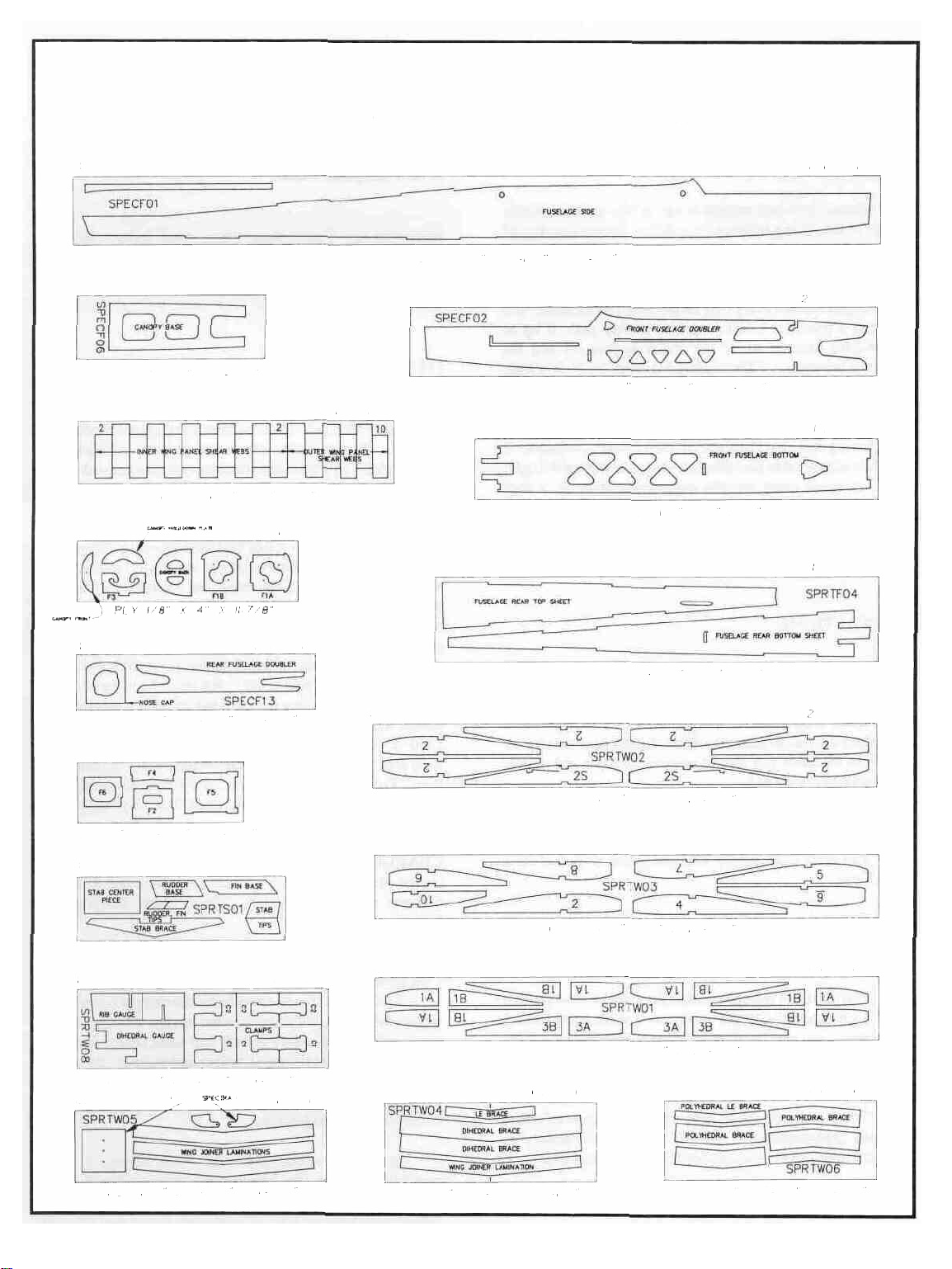
DIE PATTERNS
Do not punch out die-cut parts until you are ready to use them!
SPECFOl
SPECF06 1 PER KIT
BALSA 1/8 X 3 X 8 7/8
SPRTW07 2 PER KIT
BALSA 1/16 X 3 X 15
I
PER
SPECF05
KIT
2
PER
BALSA 3/32 X 3 1/4 X 38 1/2
SPECF02 2 PER KIT
BALSA 1/16 X 3 1/4 X 23 7/8
SPECF03 1 PER KIT
PLY
1/8 X 3 X 19
SPRTF04
1
PER
KIT
KIT
SPECF13
BALSA 1/16 X 2 5/8 X II 7/6
SPECF07 1 PER KIT
PLY
1/8 X 2
SPRTS01 I PER KIT
BALSA
SPRTW08
SPRTW05
7/8 X 7
3/16" X 3" X 9-7/8"
PLY
1/8 X 3
NOT
7/8 X II
USE0IN SPECW<
7/8
K
T I PER
2 PER
I
PER
7/8
KIT
KIT
KIT
BALSA 3/32 X 4 X 21
SPRTW02 2 PER KIT
BALSA 1/16 X 3 X 23 7/8
SPRTW03 2 PER KIT
BALSA 1/16 X 3 X 23 7/8
I
PER
SPRTW01
BALSA 1/8 X 3 X 23 7/8
SPRTW04 1 PER KIT
SPRTW06 I PER KIT
KIT
PLY
1/16 X 3
3/8 X II
7/8
PL Y 1/8 X 3
3/4 X 10
3
1/2
PL Y 1/32 X 3
1/4 X 9
3/4
Page 4

INTRODUCTION
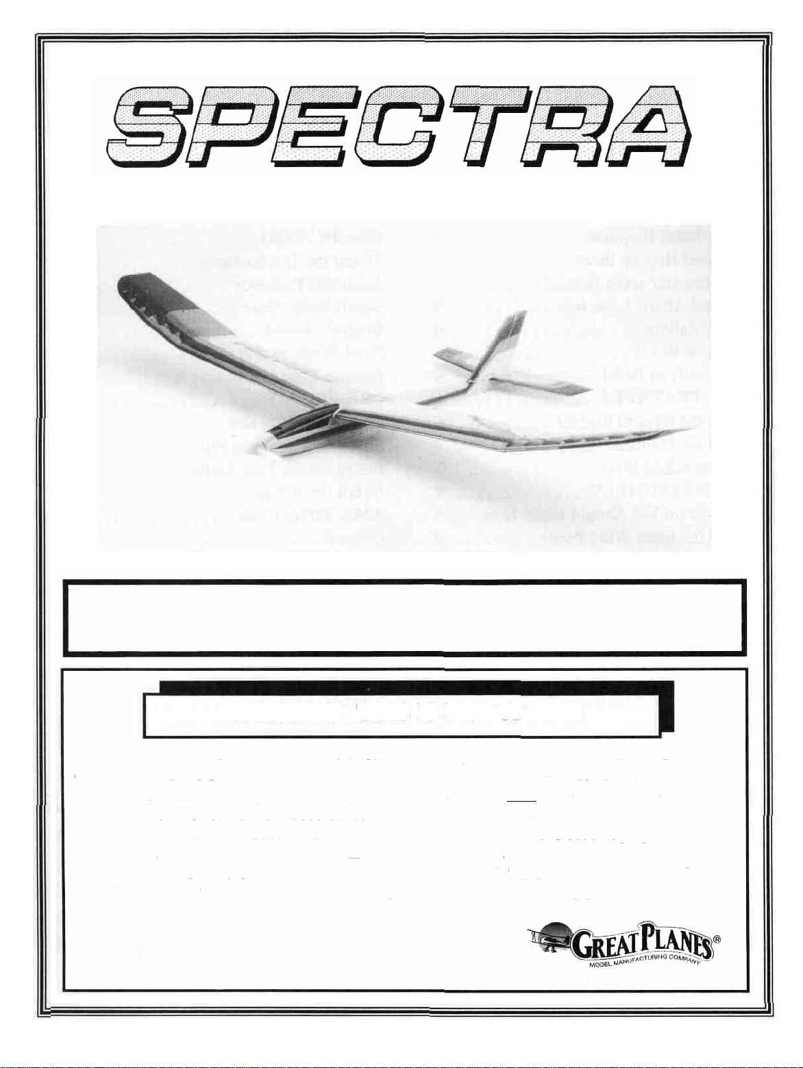
Congratulations! You are about to enter one of the most
exciting realms of radio control flying - Electric Powered
Sailplanes.
Electric powered soaring is one of the most enjoyable
types of R/C flying because it combines the convenience of
being able to fly from almost any small field with the
challenge of staying aloft for long periods of time. There is
something very gratifying about defying gravity and being
able to gain altitude using only nature's own air currents. The
Spectra's powerful Goldfire motor quickly pulls it up to
thermaling altitude where the motor is shut off and the
Spectra becomes a "Thermaling Machine". With a little
practice, you will be able to soar for hours in a single flight!
We would like to take this chance to thank you for
purchasing the Great Planes SPECTRA Electric Sailplane. It
has been designed to give you many hours of enjoyable flight,
and we spent many months engineering it to be a very
enjoyable kit to build. If you have any comments or suggestions feel free to share them with us.
PRECAUTIONS
1. You must build the plane according to the plans and
instructions. Do not alter or modify the model as doing so
may result in an unsafe or un-flyable model. In a few cases
the plans and instructions may differ slightly from the photos.
In those instances you should assume the plans and written
instructions are correct
2. You must take time to build straight, true and strong.
Note: We, as the kit manufacturer, can provide you with a top
quality kit and great instructions, but ultimately the quality
and'' fly-ability "of your finished model depends on how you
build it; therefore, we cannot in any way guarantee the
performance of your completed model, and no representations are expressed or implied as to the performance or safety
of your completed model.
Remember: Take your time and follow directions to end up with a well-built model that is
straight and true.
OTHER ITEMS REQUIRED
RADIO - A Radio having at least 2 channels is required to
control the SPECTRA (a third channel is required for throttle
control). Standard size servos can be used without any
problem but a 250 mAh receiver battery is recommended but
not required. Make sure that the radio is on an "Aircraft
Only'' frequency.
FLIGHT BATTERY - A 6 or 7 cell battery with a " Kyosho"
type connector is required to power the electric motor. We
recommend you use a 7 cell battery as it offers much higher
performance than a 6 cell battery. The capacity (mAh) of the
battery can be anywhere from 800 mAh to 1700 mAh. For
general flying a 1200 -1700 mAh 7 cell battery will provide
good power, good motor duration, and good flight performance. For contest flying an 800 - 900 mAh 7 cell battery will
provide a shorter motor duration but its lighter weight will
enable the SPECTRA to climb quicker and soar better. A
1200 -1700 mAh 6 cell battery should be used if you just want
to fly around with the motor on continuously. If your batteries
have "Tamiya" style connectors, you'll have to change the
connector on the wiring harness, or purchase a Kyosho #6195
adaptor.
3. You must use a proper R/C radio that is in first class
condition.
4. You must properly install all R/C and other components
so that the model operates properly on the ground and in the
air.
5. You must test the operation of the model before the first
and each successive flight to insure that all equipment is
operating, and you must make certain that the model has
remained structurally sound. Be sure to check the nylon
clevises often, and replace if they show signs of wear.
6. You must fly the model only with the competent help of
a well experienced R/C pilot if you are not already an
experienced and knowledgeable R/C pilot at this time.
CHARGER - A quick (15-20 Minute) charger is required to
charge your flight battery. These chargers come in many
different styles (DC, AC/DC, Timed, Peak, Temperature
Sensing, etc.).
The most inexpensive charger will be a DC Quick
Charger with a 15 - 30 minute timer. This type of charger will
work fine but you should never leave the charger unattended
while charging as the timers are not always reliable. If the
timer sticks or the battery already had some charge in it, the
battery could be over charged, heat up and explode. If you use
this type of charger, check the temperature of the battery
every couple of minutes and turn the charger off as soon as the
battery starts getting warm.
The best type of chargers are the "Peak'' chargers. They
constantly measure the voltage of the battery being charged
and when the voltage starts to drop (as the voltage of a Nicad
battery will do when it is fully charged) it will shut off. All
4
Page 5

you have to do is connect the battery, push one button and
come back when its done.
OTHER ITEMS:
Iron-on Covering Material-2 rolls (we recommend Monokote
for the wing because of its superior strength)
Latex Foam Rubber Padding (1/4" thick)
#64 Rubber Bands
OPTIONAL HOP-UP ITEMS:
FOLDING PROP - A folding prop can be used instead of the
8x4 nylon prop supplied. It will fold back against the
fuselage when the motor is not running and enhance the
soaring performance of the plane. Sonictronics makes several nice folding props and we have found the model #174
8x4 folding prop to work well on the SPECTRA with the
GOLDFIRE motor. The spinner may have to be carved out
slightly to clear a folding prop. Because the prop may have
a tendency to keep spinning after the motor is shut off, the
switch/motor should probably be re-wired to provide dynamic braking to the motor. This is easy to do and will make
the motor stop turning so the prop will fold back. There is a
sketch on page 35 showing this wiring modification.
LIGHTWEIGHT RADIO - There are several "Micro Systems" on the market that come with smaller servos, receiver
and batteries. Futaba makes a radio especially for electrics
(model 4NBL Attack E) which works well with the
SPECTRA. It comes with two S-133 Micro Servos and a 4
channel Receiver with a fully proportional electronic speed
control built in. This unit also has BEC (Battery Eliminater
Circuitry). This feature allows the radio system to be powered by the flight battery (6 or 7 cell). It will automatically
shut the motor off before the battery is totally drained, leaving
another 20 minutes or so of flying time in the flight battery.
These smaller radio systems can save several ounces of
valuable weight which will improve both the climbing and
soaring capabilities of the plane.
Your local hobby shop can be very helpful when
deciding what types of accessories to purchase. We highly
recommend that you consult with and support your local
hobby dealer when purchasing the above items. He can
also be a tremendous help if you have problems building
or flying your models.
SUPPLIES AND TOOLS NEEDED
1 oz. Thin CA Adhesive
2 oz. Medium or Thick CA Adhesive (We'll refer to it as
"thick"
2.5 oz. 30-Minute Epoxy
Hand or Electric Drill
Drill Bits: 1/16", 3/32", 1/8", 1/4"
Sealing Iron
Heat Gun
Razor Saw
Hobby Knife, #11 Blades
Pliers
Screw Drivers
T-Pins
Assorted Rubber Bands
Straightedge
Masking Tape
Sandpaper (coarse, medium, fine grit)*
T-Bar Sanding Block (or similar)
Waxed Paper
Lightweight Balsa Filler
Dremel Moto Tool or Similar (optional)
*NOTE: On our workbench, we have four 11" T-Bar sanders,
equipped with #50, #80, #100 and #150-grit sandpaper. This
setup is all that is required for almost any sanding task. We
also keep some #320-grit wet-or-dry sandpaper handy for
finish sanding by hand before covering.
in
the instructions)
A WORD ABOUT ADHESIVES
COBALT MOTORS - A GOLDFIRE motor is included in
this kit. It is a 550 size motor designed especially for
airplanes. It is an inexpensive motor that is as powerful as
many motors costing 3 times as much. We do not recommend
that you use any of the 540 size "Car'' motors. Their smaller
size and higher RPM requirements do not work well when
trying to turn a propeller at 12,000 rpm. If you want a higher
performance motor, we recommend you use an Astro Fight
.05 Cobalt Motor (Model 6605 or 6605 S). These motors are
very powerful and will make your SPECTRA climb like
crazy with some sacrifice in run time. We recommend that
you use either Sermos Power Pole Connectors or Deans Connectors on the battery and motor when using high performance motors. These connectors have a very low resistance
and will carry the larger currents better than the more popular
connectors provided.
If you looked at the "ITEMS NEEDED" list above, you
probably noticed that we recommend only two basic types of
glue for assembling the SPECTRA. . .CA adhesives and
Epoxy adhesive. Glues have come a long way in the past few
years and these two types of adhesive are all that is needed to
build a strong and light structure.
CA (Cyanoacrylate) - These are the "Super Glues". They
have revolutionized model building by eliminating the "wait
for the glue to dry'' phase of building. CA'S will be used for
95% of the building. They come in several viscosities but we
will only require the "Thin" (Runs like water) and the
"Medium" (Like a thin syrup). The thin CA will be used
where there is a nice tight fitting joint. It is applied after the
5
Page 6
parts are in position and it seeps into the joint through
capillary action and bonds the parts within a couple of
seconds. The thicker CA is applied to the parts before they are
joined and it takes up to 30 seconds to cure giving you a few
seconds to position the parts. A related and very handy
product is CA Accelerator Spray (Zip Kicker, etc.). This is
used to instantly cure CA glues of all types.
EPOXY - Epoxy adhesives are two-part resins that are very
strong but need to be mixed before they will cure. This
process along with their heavier weight does not lend itself
well to general construction. Epoxies are used where the
utmost in strength is required. They come in many different
cure times but we will only need 30 minute epoxy.
AN IMPORTANT TIP - Glue should never be
substituted for a good-fitting joint. Take a little
extra time to get a good joint and glue it properly and
it will be much stronger, much neater and much
lighter than a bad joint held together with a glob of
glue!
COMMON ABBREVIATIONS USED IN
THIS BOOK AND ON THE PLANS:
GET READY TO BUILD
NOTE: It will be helpful to build on a piece of "Celotex"
(available from a lumber co.) or other semi-soft (and flat) surface, into which you may easily suck pins to firmly hold down
the parts while building, and to avoid warps.
1. Unroll the plan sheet. Re-roll the plan inside out and let
it uncurl while you read through this instruction book. This
will help the plan lay flat and give you time to get acquainted
with the building process. NOTE: Because there are
several options to consider when building the SPECTRA,
you should read the instruction book through before
building and then go back and cross off the steps you won't
use to build your model.
2. Remove all parts from the box. As you do, figure out the
name of each part by comparing it with the plans, the die
patterns (p. 3) and the parts list at the back of this book. Write
the part name or size on each piece to avoid confusion later.
If any of the die-cut parts are difficult to punch out during
construction, do not force them! Instead, first cut around the
parts with a hobby knife. After punching out the die-cut parts,
use your T-Bar or sanding block to lightly sand the edges to
remove any die-cutting irregularities.
Elev = Elevator
Fuse = Fuselage
LE = Leading Edge (front)
Lt = Left
Ply = Plywood
Rt = Right
Stab = Stabilizer
TE = Trailing Edge (rear)
Tri = Triangle
" = Inches
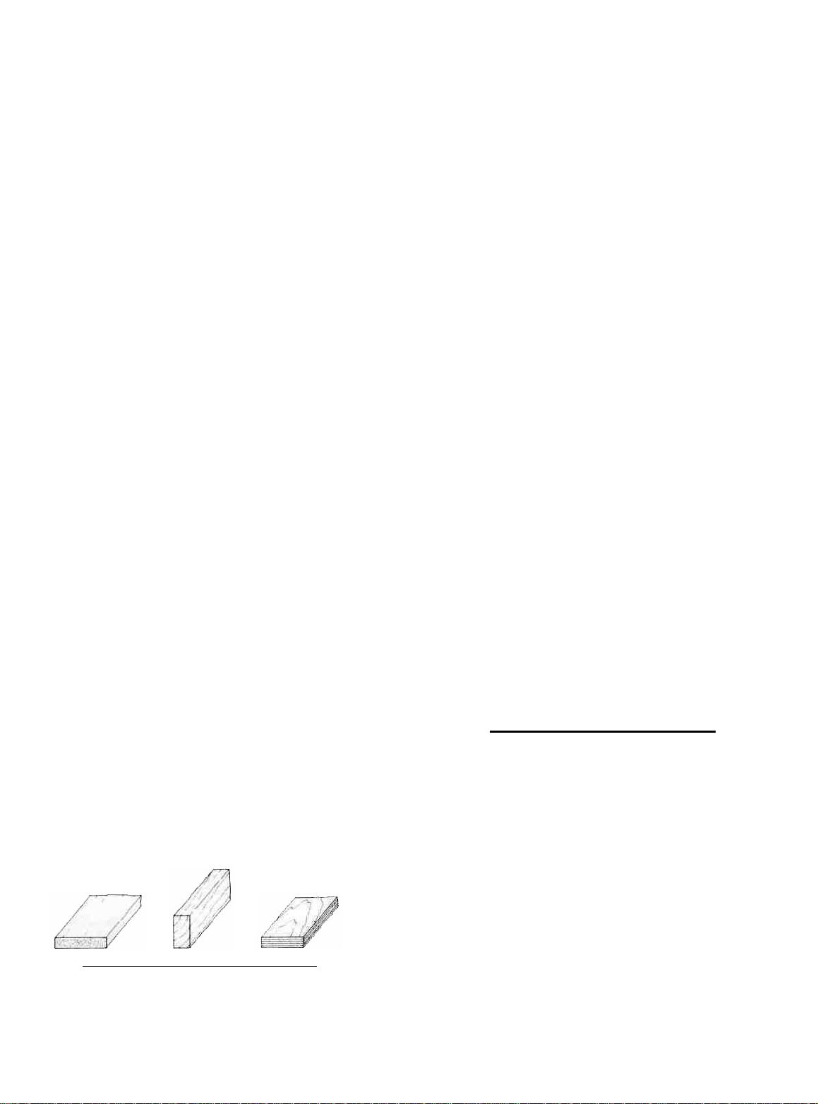
TYPES OF WOOD
NOTICE: INSTRUCTIONS IN BOXES ARE VERY
IMPORTANT AND SHOULD BE FOLLOWED CARE-
FULLY.
"TAIL FEATHERS"
BUILD THE FIN AND RUDDER
You'll need the following parts:
SPRTS02 3/16" x 3/8" x 30" Balsa Stick
SPRTS03 1/8" x 3/16" x 30" Balsa Stick
SPRTS01 3/16" Die-Cut Balsa Tail Parts
SPECF08 3/16" Balsa Triangle
BALSA BASSWOOD PLYWOOD
D 1. Tape or pin the plan down to your flat work surface.
Tape a piece of waxed paper over the fin and rudder portion
of the plan (so you don't glue the parts to the plan).
6
Page 7
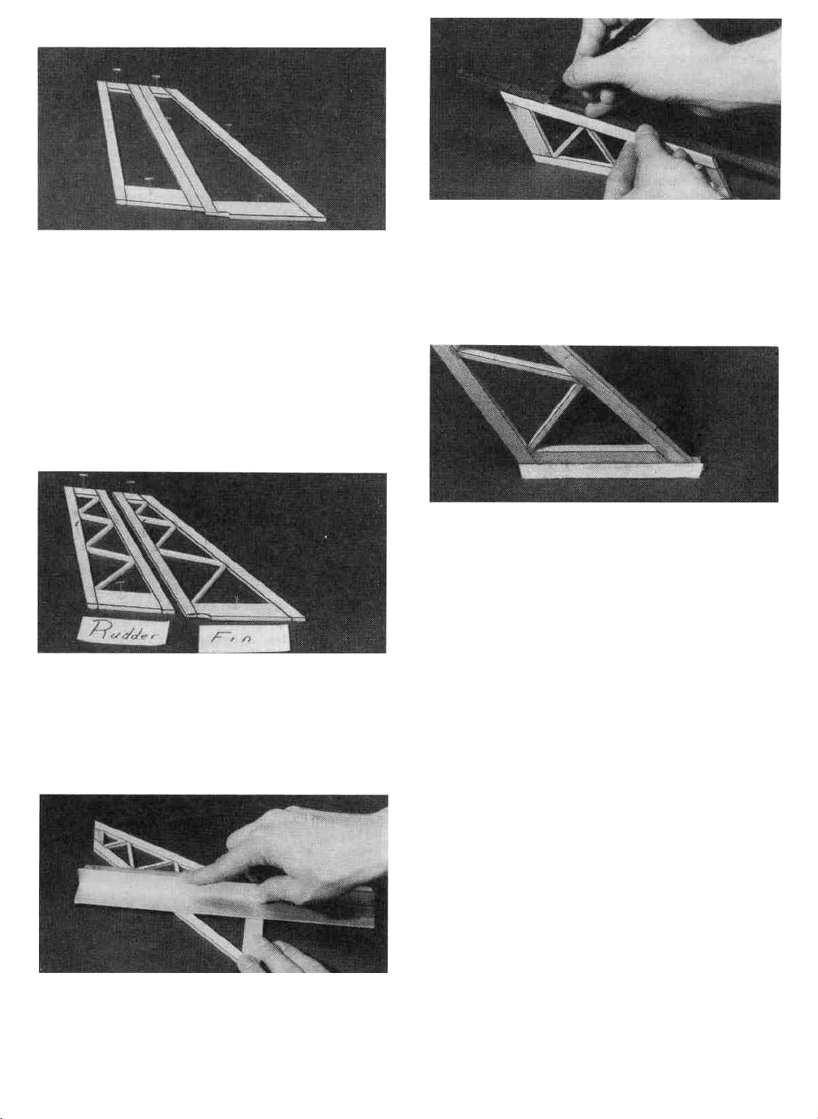
D 2. Using the plan as a guide, cut pieces of 3/16" x 3/8"
balsa (from the 30" sticks, SPRTS02) to make the Rudder
and Fin Framework. NOTE: Cut the Fin L.E, the Rudder
L.E. and the Rudder T.E. from a single SPRTS02 (this will
leave enough long pieces for the stab frame). Punch out the
die-cut Fin Tip, Rudder Tip, Fin Base and Rudder Base
from SPRTS01. Sand any rough edges on these pieces and
then pin them in place on the plan. Glue the parts together
using thin CA glue. CAUTION: Do not glue the fin to the
rudder!
D 3. From the 1/8" x 3/16" x 30" sticks (SPRTS03), cut
the diagonal "ribs" to fit between the rudder and fin framework, and glue them in place. NOTE: It is not necessary to
get these ribs in the exact position shown on the plan.
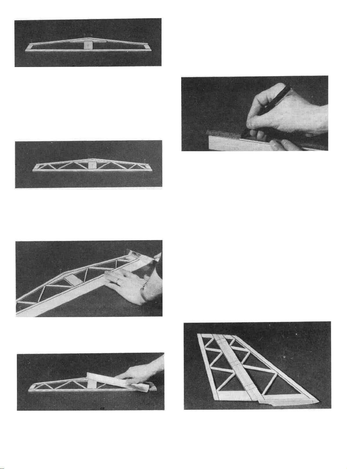
D 5. Carefully draw a centerline all around the edges of
the rudder (this will help to maintain symmetry when sanding).
D 6. Cut 4-1/8" off of the 3/16" Balsa Triangle (SPECF08)
and glue them along the bottom of the fin. The bottom edges
of the triangle should be flush with the bottom of the fin.
D 7. Using a sanding block and coarse (50 or 80-grit)
sandpaper, sand the leading edge of the rudder to the V-shape
as shown on the plans (a small razor plane works great for
initial shaping). Sand the three remaining edges to a smooth
rounded shape. Sand the top and the leading edge of the fin
to a nice rounded shape*. NOTE: The trailing edge of the
FIN must remain square, do not round it! Sand the triangle
stock to blend with the leading and trailing edges of the fin.
Also, cut or sand the bottom of the triangle stock to match the
contour of the 3/16" die-cut fin bottom.
D 4. Remove the fin and rudder assemblies from the plan
and examine them for any open or bad joints. Fill any gaps
with thick CA, then use your sanding block with medium grit
sandpaper to sand both sides of the framework smooth.
* MAXIMUM PERFORMANCE TIP - Sand both sides of
the rudder to a taper as shown on the plans. This requires a
little more work but will help to reduce drag and thus increase
performance of the sailplane.
BUILD THE STABILIZER AND ELEVATOR
You'll need the following parts:
SPRTS02 3/16" x 3/8" x 30" Balsa Sticks
SPRTS03 1/8" x 3/16" x 30" Balsa Slicks
SPRTS01 3/16" Die-Cut Tail Parts
SPRTS04 Tapered Elevator
7
Page 8
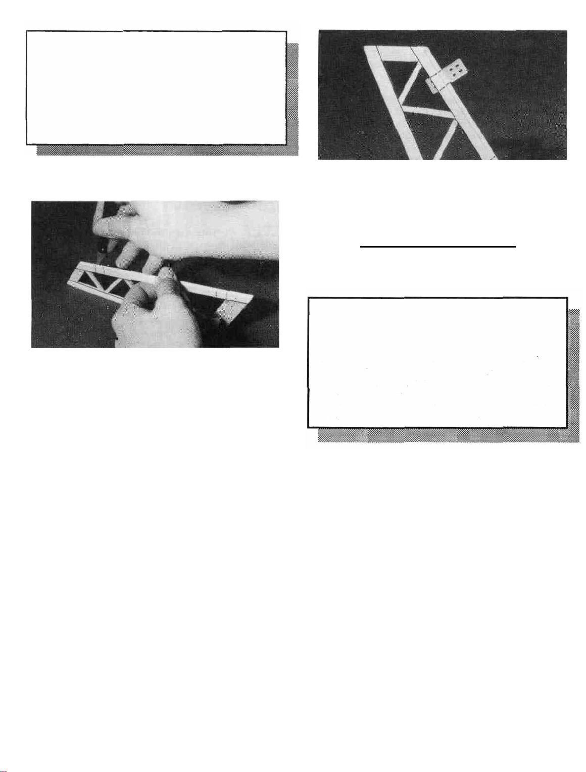
D 1. Tape waxed paper over the stabilizer drawing on
the plan so you don't glue the parts to the plan. Using the plan
as a guide, cut the 3/16" x 3/8" balsa pieces from SPRTS02.
Punch out the die-cut Stab Tips, Stab Center and Stab
Brace from SPRTS01 and sand the edges if necessary to
remove any "fuzz''. Assemble the stab framework by pinning
everything in place on the plan. Glue the parts together using
thin CA glue.
D 2. Cut and sand the 1/8" x 3/16" "ribs" (from
SPRTS03) to length and glue them in place. NOTE: It is not
necessary to get these ribs in the exact position shown on the
plan.
D 5. Tape the elevator to the stab using masking tape and
sand the leading edge of the stab, the stab tips and the elevator
tips to a smooth rounded shape. The tips of the elevator
should blend in nicely with the stab tips.
D 6. Remove the elevator and draw a center line down its
leading edge. Use your sanding block to sand the same Vshape as you did on the rudder. The trailing edge should also
be sanded to a smooth rounded shape. Apply thin CA the the
tips of the elevator to harden the wood, and help protect it
from damage.
CUT THE HINGE SLOTS (Do not glue)
D 3. Pin or tape the elevator (SPRTS04) in place behind
the stab and use your razor saw to cut the ends off to match the
stab. Sand the the two front comers of the stab to round them
off.
NOTE: One-piece molded polypropylene hinges are supplied
in this kit. We have tested many different hinges and have
found that these hinges are one of the best available. We
recommend that you use these hinges and follow the instructions
below to install them. If you choose to use these hinges or the
"pinned"-type hinges, you should cut the hinge slots at this
time. However, if you choose to use the one-piece hinges that
are paper covered for CA glue installation, you may wait until
after covering before cutting the hinge slots.
D 4. Remove the stab from the plan and examine it for
any open or bad joints. Fill any gaps with thick CA, then use
your sanding block with medium grit sandpaper to sand both
sides smooth. Carefully draw a centerline around the edges
of the stab (this will help maintain symmetry when sanding).
D 1. Lay the rudder and elevators on the plan and mark
the hinge locations. Place the rudder against the fin TE and
transfer the marks over to the fin. Place the elevator against
the stab TE and transfer the marks over to the stab.
8
Page 9
CAUTION!!!: You must use extreme care when
cutting hinge slots with a hobby knife, to avoid
cutting yourself! If the balsa part breaks while
you are pushing on the knife, the blade could go
into your hand before you know it! A good
precaution is to wear leather gloves while
performing the following steps.
WING ASSEMBLY
A DECISION YOU SHOULD MAKE NOW...
"WING CONFIGURATION"
D 2. Draw accurate centerlines down the trailing edge of
the stab and the fin. Cut the hinge slots on these lines using
a hobby knife or a slotting fork and slotting hook. (The
recommended hinge slotting technique is listed below).
A. Begin by carefully cutting a very shallow slit at
the hinge location. This first cut is to establish your cut
in the right place, so concentrate on staying on the
centerline and don't cut too deep!
B. Make three or four more cuts in the same line,
going slightly deeper each time. As you make these
additional cuts, work on going straight into the wood.
Continue this process while "wiggling" the knife handle
forward and backward until the blade has reached the
proper depth for the hinge.
C. Trial fit the hinge into the slot. If the hinge is
difficult to push in, re-insert the knife and move it back
and forth in the slot a few times to enlarge the slot.
D 3. IMPORTANT! Condition or "break-in" the hinges
by folding them back and forth several times.
The SPECTRA kit has two different wing options: a twopiece wing or a one-piece wing. The two-piece wing is the
standard way to build the wing and it is much easier to
transport. The instructions also explain how to build the wing
in one piece which makes it a little stronger but makes it
harder to transport in today's small cars
BUILD THE INNER WING PANELS
You'll need the following parts:
SPRTW01 1/8" Die-Cut Balsa Wing Ribs
SPRTW02 1/16" Die-Cut Balsa Wing Ribs, W2. W2S
SPRTW03 1/16" Die-Cut Balsa Wing Ribs, W2, W4-
W10
SPRTW04 1/8" Die-Cut Plywood Dihedral Braces
SPRTW07 1/16" Die-Cut Balsa Shear Webs
SPRTW08 1/8" Die-Cut Plywood Clamps and Gauges
SPRTW10 Shaped Balsa Leading Edge
SPRTW 11 Shaped, Notched Balsa Inner Trailing Edge
SPRTW13 1/8" x 5/16" x 23-1/2" Basswood Spars
SPRTW17 1/16" x 3" x 24" Balsa Wing Sheeting
D 4. Insert the hinges into the slots and trial fit the rudder
and elevator in place on the fin and stab. Do not glue the
hinges until after you have covered the model. The photo
for this step is at the top of the next column.
NOTE: The wing is designed to be built as a two-piece wing;
however, we also describe how to build a one-piece wing.
Page 10
D 1. Tape the plan to your flat work surface, and cover
the wing drawing with waxed paper. NOTE: If your work
space is limited, you may cut the wing drawings apart from
the rest of the plans.
D 2. The Shaped Wing Leading Edges (SPRTW10) are
fastened together by thin strips of balsa. Separate them by
carefully cutting between the LE'S. Sand away the excess
balsa that remains along the edges after cutting them apart,
using a sanding block with 100-grit sandpaper. Be careful
when cutting and sanding to follow the contour of the LE'S
and don't sand any more than necessary, otherwise they
may not match up with the ribs and sheeting.
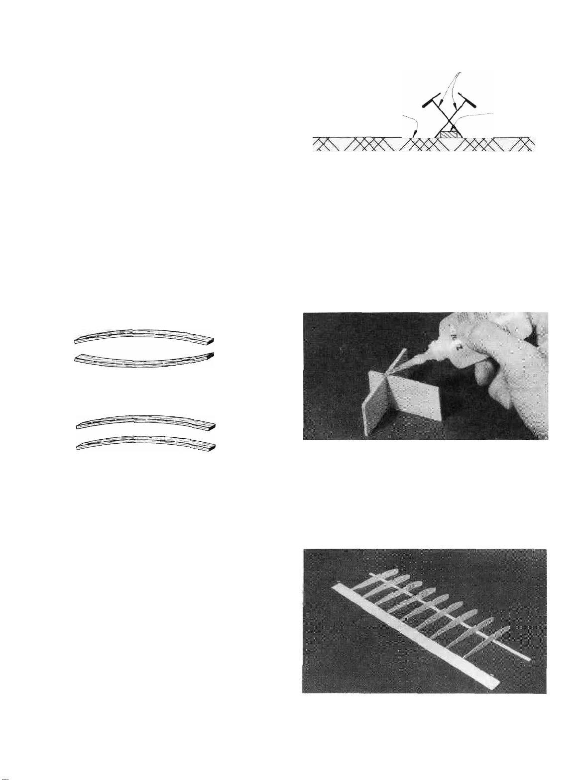
D 3. Before using the 1/8" x 5/16" x 23-1/2" Basswood
Spars (SPRTW13), examine them carefully for possible
imperfections. Look for knots, soft spots, diagonal grain and
any other imperfections. If possible, position each spar so the
imperfections are on the outer half of the wing panel (toward
the tip), where they will be least affected by high stress. If the
spars are warped slightly, "balance them out" by installing
the warped spars in opposite directions (see sketch).
TWO WARPED SPARS INSTALLED
THIS WAY WILL RESULT IN A
STRAIGHT WING
NOTE: The spars may be cut slightly too long. The excess
will be cut off later.
T-Pins
Work Surface
DD 7. Place the seven W-2 ribs (from SPRTW02 and
SPRTW03) and the two W-2S ribs (from SPRTW02) on the
spar in their approximate positions, work the ribs into the
notches on the trailing edge but do not glue anything yet.
Spar
TWO WARPED SPARS INSTALLED
THIS WAY WILL RESULT IN A
WARPED WING
D 4. Carefully punch out all the die-cut 1/16" Balsa W2
and W2S Wing Ribs. Sand the edges slightly to remove any
die-cutting irregularities. The W2S ribs have a die-cut notch
to clear the spoilers in the SPIRIT kit and are not used in this
kit so just treat them like a W2 rib and do not punch out the
notch.
NOTE: Begin building the LEFT wing panel, starting at
step 5 on page 10. Continue through step 8 on page 15.
Next, repeat these steps to build the right wing panel.
DD 5. Pin one of the notched balsa Inner Trailing
Edges (SPRTW 11) to the plan lining up the notches in the TE
with the notches on the plan. Notice that the notches near W3
are only 1/16" wide since half of the 1/8" wide rib notch is in
the inner T.E. and the other half is in the outer T.E..
DD 8. Punch out the two Rib Gauge Pieces from the
1/8" die-cut plywood sheet (SPRTW08) and assemble them
using CA. Notice that one end of the gauge is slanted at a 5
degree angle for positioning the end ribs. The other 3 ends are
perpendicular and can be used to keep parts 90 degrees to the
work surface.
DD 6. Place one of the 1/8" x 5/16" x 23-1/2" Basswood
Inner Spars (SPRTW13) on the wing plan and pin the spar
down with crossed T-pins as shown in the following sketch.
DD 9. Make sure the ribs are properly positioned accord-
ing to the plans and glue them in place using thick CA at the
spar joint and a drop of thin CA at the trailing edge joint. Use
10
Page 11
the square end of the rib gauge to keep the ribs perpendicular
to the work surface.
DD 10. Trial fit the top 1/8" x 5/16" x 23-1/2" Basswood
Inner Spar (SPRTW13) into the notches in the ribs by
carefully pushing the spar completely down into the notches.
Make sure the top spar is lined up lengthwise with the bottom
spar. Remove the spar and glue it in place by applying thick
CA to the notches before the spar is put back in place.
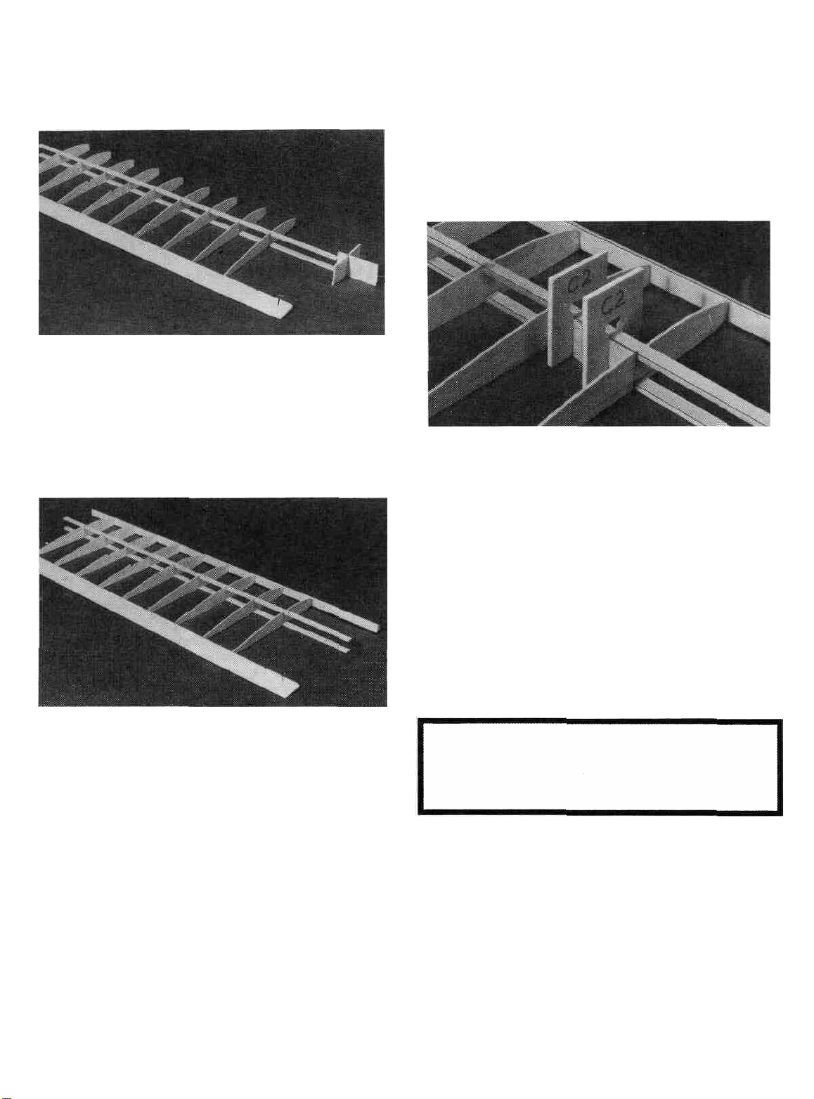
DD 12. Locate the 1/16" Balsa Die-Cut Shear Web
Sheet (SPRTW07) and notice that all of the shear webs are
not the same. The webs between the stamped number 2's are
for use on the inner panel. The webs between the 2 and the 10
are for the outer panel and each one of these is a different size
so keep them in the sheet until they are ready to be used.
Punch out all of the "2" shear webs.
DD 13. Trial fit one of the webs in place between the first
two W-2 ribs. You may have to sand it slightly to get it to fit.
Glue the shear web in place on the back of the spars using
thick CA. The webs should be centered between the spars. It
is important to do a good job of gluing these in place as they
are responsible for most of the wing's strength. C-2 Clamps
from the 1/8" Die-Cut Plywood Sheet (SPRTW08) can be
used to help hold the webs in place while the glue cures.
DD 11. Position a Pre-shaped Leading Edge (SPRTW 10)
in place over the plans. NOTE: These leading edges are
NOT symmetrical. Refer to the wing end view on the plan
to determine which way they should be installed. Carefully
hold the leading edge against one of the end W-2 ribs and note
that it is wider than the front of the rib. This is because the 1/
16" balsa leading edge top sheeting will be added later. Align
the lower surface of the leading edge with the bottom of the
rib and glue it in place with a drop of thin CA (there must be
a 1/16" gap between the top of the rib and the top of the LE
so the sheeting will fit). Lift up the other end of the leading
edge, align it with the bottom of the opposite end W-2 and
glue it with a drop of thin CA. Go down the line and glue the
remaining ribs to the leading edge one at a time so you can
make sure they are aligned. CA Accelerator may come in
handy for speeding up this process if you don't want to hold
the LE in place long enough for the glue to cure naturally.
DD 14. Install the remaining balsa shear webs. Note that
the webs are only installed between the ribs already glued in
place. Three webs are also installed on the front of the spars
in the first three rib "bays". Remove the T-Pins as the webs
are installed but make sure the panel is kept flat throughout
this process.
IF YOU ARE BUILDING A ONE-PIECE WING, SKIP
AHEAD TO "BUILD THE OUTER WING PANELS"
ON PAGE 13. STEPS 15 THROUGH 23 ARE FOR A 2PIECE WING ONLY.
DD 15. Locate the 1/8" die-cut sheet (SPRTW04) that
contains the Dihedral Braces, the Leading Edge Brace and
the Wing Joiner Lamination. Line a ruler up with the two
embossed cut marks and draw a line across both of the
dihedral braces.
DD 16. Punch out the two dihedral braces and cut them in
half with a razor saw along the lines you just drew. Note:
these braces are supplied in one-piece for the one piece
option. Also punch out the wing joiner lamination from that
11
Page 12

sheet and set it aside for the next step. The leading edge brace
is not used in a two-piece wing.
but be careful not to get any excess glue inside the box formed
by these braces, or the wing joiner will not fit inside. Also test
the size of the joiner box with the joiner lamination while the
glue is curing. Be careful: don't glue the joiner lamination.
DD 19. Tightly wrap the joiner box with a strong thin
thread and then soak it with thin C/A. This will add a lot of
strength to the joiner box. Do not overlap the thread or allow
it to build up too thick.
DD 17. Punch out the three C1 clamps from the 1/8" diecut plywood sheet (SPRTW08). Test fit two of the dihedral
brace "halves" to the "root" (inner) end of the inner panel
spars. One brace should be installed on the front of the spars
and the other on the back. The edge that you cut with the razor
saw should be near the end of the spars and it should be placed
so that it slants in at the top (short edge at top). Use the C1
clamps to hold the braces in place and test fit the wing joiner
lamination into the box formed. This "box'' will be referred
to as the "joiner box". The wing joiner lamination is used to
make sure the spars remain the correct distance apart.
DD 20. Locate one of the 1/16" x 3" x 24" Balsa Sheets
(SPRTW17) and cut it into 8 pieces 2-3/8" long. Slide one of
the sheets in place in front of the joiner box and trim to fit as
shown in the photo. Use another piece of sheeting to shim the
front edge up against the bottom of the ribs as shown in the
following sketch. Glue it in place, 1/16" Balsa
bottom sheet
1/16"
balsa
scrap
Work Surface
DD 18. Remove the clamps and apply a bead of epoxy or
thick CA along the spar edges. Install the braces and hold in
place with the C1 clamps. A good glue joint is important here
DD
21.
Glue another piece to the rear of the joiner box and
then cut a third piece to fit behind the second and glue it in
place.
12
Page 13

DD 22. Punch out three W1A ribs and three W1B ribs
from the 1/8" die-cut balsa rib sheet (SPRTW01). Test fit
these ribs into position. A little sanding may be necessary to
make them fit properly. Glue these ribs into place using thick
CA. The end rib should be tilted in at the top using the slanted
end of the rib gauge to give it the correct angle.
with a thick CA at the spar joint and a drop of thin CA at the
trailing edge joint. Use the rib gauge to keep the ribs
perpendicular.
DD 4. Trial fit the top 1/8" x 5/16" x 15-1/8" Basswood
Outer Spar in place by carefully pressing the spar into the
notches until it is flush with the top of the ribs. Remove the
spar and apply thick CA to the notches. Replace the spar and
allow the glue to cure.
DD 23. Cut and sand the leading edges, trailing edges and
spars to their correct length.
BUILD THE OUTER WING PANEL
You'll need the following parts:
SPRTW03 1/16" Die-Cut Balsa Wing Ribs W4 - W10
SPRTW07 1/16" Die-Cut Balsa Shear Webs
SPRTW10 Shaped Balsa Leading Edge
SPRTW 12 Shaped, Notched Balsa Outer Trailing Edge
SPRTW14 1/8" x 5/16" x 15-1/8" Basswood Outer Spars
SPRTW15 7/8" Shaped Balsa Wing Tip Block
DD
1.
Lay one of the Outer Trailing Edges (SPRTW12)
in place over the plan. Align the notches in the trailing edge
with the notches on the plans and pin it in position. NOTE:
The un-notched end of this trailing edge is not used and
goes out toward the tip of the panel. Cut the extra trailing
edge off 1/4" past the last notch.
DD 2. "Cross pin" one of the 1/8" x 5/16" x 15-1/8"
Basswood Outer Spars (SPRTW14) in place.
DD 5. Lay one of the remaining Pre-Shaped Leading
Edges over the LEADING EDGE TEMPLATE at the top
right comer of the plans. Use this drawing as a reference to
cut the leading edge to length and to cut the relief notches. It
is a good idea to cut the leading edge approximately 1/4"
longer on both ends to be on the safe side. It can be cut to
the correct length after it is installed. The relief notches do
not need to go all the way through the leading edge but should
go within 1/8" of doing so. NOTE: you need to make a
"right" and a "left" LE.
DD 6. Carefully bend the leading edge to the angle
shown on the plans and position it against the ribs. The bends
should be at ribs W6 and W9. Align the leading edge with the
ribs and glue it in place just as you did for the inner panel
except start at ribs W6 and W9. Also note that there is no
sheeting on the outer panel so the ribs are the full height of the
LE.
DD 3. Punch out the 1/16" (W4-W10) Tip Ribs out of
one of the SPRTW03 die-cut sheets. Glue the ribs in place
DD 7. Punch out the remaining 6 shear webs (from
SPRTW07) and lay them end to end so that the end of one web
is the same size as the end of the one next to it as shown in the
sketch below. This is the order and direction they will be
installed in the wing. The shortest web goes between ribs W9
& W10 and the longest web goes between ribs W4 & W5.
NOTE: These webs are actually tapered to match the
taper of the wing. There is a sketch at the top of the next page
to illistrate this taper.
13
Page 14

NOTE TAPER OF WEBS
W9-W10 W8-W9 W7-W8 W6-W7 W5-W6 W4-W5
DD 8. Glue the webs into their respective places using
thick CA. The thinnest end of each web goes towards the tip
of the panel.
DD 9. Cut and sand the trailing edge, spars and leading
edge flush with rib W10.
DD 10. Glue the 7/8" x 1-3/16" x 6-1/4" Triangle Wing
Tip Blocks (SPRTW15) to W10 with thick CA. The sketch
below and the cross sections on the plan shows how the block
should be attached to get the correct tip shape.
Tip
Rib
W10
Wing Tip Block
DD 11. Carve and sand the wing tip to blend with rib W10.
Be careful not to change the shape of W10 while sanding the
tip. There are three section views on the left wing plan and
three photos above to help show you the desired shape. Do
not sand the trailing edge of the tip too thin or it will get
damaged easily; 1/16" thick is fine.
DD 12. Apply several drops of thin CA to the rear portion
of the balsa wing tip. Allow the glue to soak into the wood and
cure. The glue will help harden the wood and protect it from
damage.
14
Page 15

JOIN THE INNER AND OUTER WING
PANELS
You'll need the following parts:
SPRTW06 1/32" Plywood Polyhedral Braces
SPRTW08 1/8" Plywood Clamps and Gauges
DD 1. Prop up the outer panel 2-5/8" (from the work
surface to the bottom of W10) using the lower notch in the
Dihedral Gauge (from SPRTW08) next to rib W9. The
notches in the dihedral gauge are a tight fit so they will stay
in place once positioned. Use a sanding block to carefully
sand the leading edge, spars and trailing edge to achieve
vertical surfaces on each as shown in the photo. Check your
progress by occasionally setting the panel on the plans to
make sure you are not sanding any "sweep" (forward or
backward tilt) into the wing panel.
correct angle. Sand any ends if needed to make everything fit
well. The photo for this step is below.
DD 4. With the dihedral gauge in place. Apply thick CA
or epoxy to the leading edge, trailing edge and spar joints to
"tack glue" the two panels together. Hold every thing in place
until the glue has cured.
DD 5. Punch out two of the 1/32" Plywood Polyhedral
Braces from the die-cut sheet (SPRTW06) and test fit them
in place against the front and back of the spars. Sand them if
needed to achieve a good fit.
DD 2. With the inner panel flat on the work surface and
your sanding block perpendicular to the work surface, sand
the leading edge, spars and trailing edge (the outer end) so
they are all even and of the correct length.
DD 3. Test fit the inner and outer panels together over
the plan to make sure the leading edges, spars, and trailing
edges all meet up nicely when the tip panel is blocked up the
required 2-5/8" (at the bottom of rib W10) with the lower
notch of the dihedral gauge. The plans show where the
dihedral gauge should be placed (next to W9) to achieve the
DD 6. When satisfied with the fit apply a generous bead
of epoxy or thick CA to the spars and install the braces on both
sides of the spars. Center the braces between the spars and use
the die-cut C2 Clamps (from SPRTW08) to hold everything
in place.
DD 7. Glue the 1/32" Plywood Leading Edge Brace
(from SPRTW06) in place against the leading edges. Align
the brace with the bottom of the leading edge to allow for the
1/16" balsa leading edge sheet which will be applied later.
DD 8. Install ribs W3A and W3B between the inner and
15
Page 16

outer panels using thick CA as shown in the photo. A little
sanding may be necessary to achieve a good fit.
D 9. Now go back to step 1 and assemble the other half of
the wing.
FINAL WING ASSEMBLY
IF YOU ARE BUILDING A ONE-PIECE WING SKIP |
AHEAD TO STEP 4 |
to the aluminum joiner blade. Glue the 1/8" ply joiner and the
other 1/16" ply joiner to the aluminum joiner blade (refer to
the sketch at step 1) using the same procedure. Apply as much
pressure (clamps, clothespins, weights, etc.) as possible while
the glue is curing and be sure to accurately line up the pieces.
D 3. Sand the edges of the finished "wing joiner" to remove
any glue globes and test fit it in the wing joiner box. Some
sanding may be required to get a nice smooth but not loose
fit. If the joiner is loose, thick CA or epoxy may be used to
"build up" the joiner anywhere it may be needed to achieve a
nice fit in the wing.
You'll need the following parts:
Aluminum wing joiner blade, 1/8" ply joiner and two
1/16" ply joiners.
1/16" Ply Joiner
1/8" Ply Joiner
Aluminum Joiner Blade
1/16" Ply Joiner
D 1. We have included a "high strength" aluminum wing
joiner blade in this kit. If you are going to build your Spectra
with a two piece wing, use the aluminum joiner blade, a 1/8"
ply joiner and two 1/16" ply joiners as shown above. Sand the
sides of the aluminum joiner with coarse grit sandpaper and
then thoroughly clean it with rubbing alcohol before gluing in
place. If you are building the one piece wing, the aluminum
joiner is not necessary.
IF YOU ARE BUILDING THE TWO-PIECE WING
SKIP AHEAD TO STEP 13
D 4. Prop up one wing half 2" (as measured from the work
surface to the bottom of rib W3) and sand the root (Inner) end
of the trailing edge, spars and leading edges to achieve vertical
surfaces as you did earlier for the outer panels. Do the same
for the other wing panel.
D 5. Test fit the two inner panels together by laying one panel
flat on the work surface and using the dihedral gauge to prop
up the other panel 4" (at the bottom of rib W3). Use the
dihedral gauge next to the last W2 rib to achieve the correct
angle. Make sure that each spar, etc. just touches the opposite
spar, etc. of the other panel. Carefully sand the longest ends
until a good joint is achieved between each member.
D 2. Use 30-minute epoxy to glue one of the 1/16" ply joiners D 6. Punch out all four of the Wing Joiner Laminations,
16
Page 17

the Dihedral Braces and the Leading Edge Brace from the
die-cut sheets SPRTW04 and SPRTW05. Test fit all of the
pieces in place and sand them if necessary to make them fit
nicely. The wing joiner laminations are installed between the
spars and are sandwiched in place by the dihedral braces. The
C1 clamps can be used to hold everything in place.
D 7. When satisfied with the fit, mix up a batch of epoxy
(30 minute cure time is ideal, 5-minute is too fast), coat the
joiner laminations with a layer of epoxy and install the joiner
laminations between the spars. Quickly apply some epoxy to
the dihedral braces and hold them in place using the C1
clamps. Also apply some glue to the leading and trailing
edges and pin them together to keep them aligned with one
another. Wipe off any excess epoxy that may have squeezed
out before it cures. After the glue cures sand off any glue
globs that may have formed.
D 8. It is not necessary to wrap the dihedral braces with
thread when assembling a one-piece wing. Just disregard any
references or photos showing the thread.
D 10. Locate one of the 1/16" x 3" x 24" Balsa Sheets
(SPRTW17) and cut it into 8 pieces 2-3/8" long. Slide one of
the sheets in place in front of the dihedral brace, trim it to fit
and glue it to the LE and the dihedral brace with thick CA.
Press the sheeting in place to make it conform around the
thread. A second piece of balsa can be used as a shim to hold
the sheeting against the LE as shown in the sketch at step 20
on page 12.
D 11. Glue another piece of 1/16" sheeting to the rear of
the dihedral brace, then cut a third piece to fit behind the
second and glue it in place.
D 12. Punch out six W1A ribs and six W1B ribs from the
1/8" die-cut balsa rib sheet (SPRTW01). Test fit these ribs
into position. A little sanding may be necessary to make them
fit properly. Glue all six W1A ribs and all six W1B into place
using thick CA (the two center W1B ribs are glued together).
D 9. Glue the 1/8" Plywood Leading Edge Brace in
place using thick CA. It should be centered (up and down) on
the leading edge because 1/16" sheeting will be added above
and below it later.
D 13. Sand the top LE surface of the ribs with a sanding
block to remove any bumps or high spots, but be very careful
not to change the shape of the airfoil. Set the 1/16" x 3" x 24"
Balsa Leading Edge Sheeting (SPRTW17)in place on the
inner panel. The outer end of the sheeting should cover rib
W3A. Apply several strips of masking tape to hold it in place
and act as a hinge for the gluing process.
17
Page 18

D 14. Press the sheeting into place and trim it flush with
the back edge of the spar using a modeling knife and straightedge.
D 17. Use the remaining 1/16" balsa sheeting to sheet the
top inboard center section out past rib W1B as shown in the
photo. Thick CA should be used for this step. Glue the first
piece near the spars, and add the final piece near the trailing
edge. Sand the sheeting flush with the W1A and W1B ribs at
the wing root.
D 15. Lift the sheeting up and apply a bead of thick CA
along the top spar and the second W1A rib. Quickly press the
sheeting down into place and hold until the glue has cured. A
straight strip of wood the length of the panel can be a big help
when trying to hold the sheeting down evenly.
D 16. Apply a small bead of thin CA between the pieces of
masking tape along the leading edge. When all of the glue has
cured, remove the tape, flip the wing over and securely glue
the sheeting to the ribs and the leading edge using thin CA.
The photo for this step is at the top of the next column.
D 18. If you built a two-piece wing, trial fit the two wing
halves together using the plywood wing joiner. Sand the root
of each panel if necessary to achieve a nice fitting joint
between the two wings. If there are large gaps, glue a scrap
piece of 1/16" balsa to the root of each panel and sand it to fill
the
gap.
LEFT WING
PANEL
1/16"
Ply
Wing Protectors
D 19. Sand three edges (two short and one long edge) of
each 1/16" Plywood Wing Protector (SPRTW18) to a taper
18
RIGHT WING
PANEL
Tapered
T.E.
Page 19

as shown on the plans and glue them in place on top of each
trailing edge. They should be oriented so the unsanded edge
is flush with the back of the trailing edge and they should be
placed 9/16" away from root of the wing. These will protect
the wing trailing edge from being dented by the rubber bands.
FUSELAGE ASSEMBLY
holes, about 1/2" apart, where the black dots are in the photo
and apply a couple of drops of thin C/A to each hole. The thin
C/A will soak into the wood and provide a good bond.
You'll need the following items:
SPECF01 3/32" Balsa Fuselage Sides and Wing Saddle
Tripler
SPECF02 3/32" Balsa Fuselage Doublers
SPECF03 1/8" Plywood Front Fuselage Bottom
SPRTF04 1/16" Balsa Rear Fuselage Sheeting
SPECF05 1/8" Plywood Formers
SPECF07 1/8" Plywood Formers
SPECP08 3/16" x 15" Balsa Triangle
SPECF13 1/16" Balsa Nose Cap and Rear Doubler
SPECF15 Balsa Top Nose Block
DOWEL030 1/4" Hardwood Wing Dowel
ASSEMBLE FUSELAGE SIDES
D 1. Pin or tape the fuselage plan to your flat work
surface and cover it with waxed paper. Lay one of the 3/32"
Die-Cut Balsa Fuselage Sides (SPECF01) down ABOVE
the FUSELAGE SIDE VIEW so you can use the plan for
reference. This is going to be the LEFT fuselage side.
DD 3. Glue the 1/16" Die-Cut Balsa Rear Fuselage
Doubler (SPRTF13) in place making sure it lines up with the
fuselage side. Use a T-pin to poke holes where the black dots
are in the photo and put a couple of drops of thin C/A in each
hole and around the edges.
DD 4. Glue one of the 3/32" Die-Cut Balsa Wing Saddle
Triplers (SPECF01) in place on top of the front fuselage
doubler. The tripler should be flush with the top of the
doubler but do not let it overlap the notches for the formers.
Sand the edges of the doublers/tripler flush with the edge of
the fuselage side.
DD 2. Trial fit one of the 1/16" Die-Cut Balsa Front
Fuselage Doublers (SPECF02) onto the 3/32" Balsa Fuselage
Side.
Line
the edges of the fuselage side (except the front). Note that the
doubler is 1/8" shorter in front than the fuse side. It is
important to get this doubler properly aligned since all of the
formers will key into it. With the doubler in place, apply thin
C/A around all edges and cutouts. Use a T-Pin to poke a few
up the doubler so the edges of it
are
even
with
D 5. Go back to step 2 and assemble the RIGHT fuselage
side. The easiest way to do this is to lay the other fuselage side
upside down below the one you just built as shown in the
photo. MAKE SURE YOU ARE NOT BUILDING TWO
IDENTICAL SIDES, THEY SHOULD BE THE OPPOSITE OF EACH OTHER.
19
Page 20

FRAME-UP THE FUSELAGE
D 1. Lay a piece of waxed paper over the FUSELAGE
TOP VIEW. Assemble but do not glue yet, the 1/8" Die-Cut
Plywood Front Fuselage Bottom (SPECF03) and the 3/32"
Die-Cut Balsa Rear Fuselage Bottom (SPRTF04) together
over the FUSELAGE TOP VIEW on the plans. Make sure the
bottoms are aligned with the plan and that both pieces are
pushed firmly against the work surface to even up the bottoms. If the joint is a nice tight fit, apply thin CA to the joint.
If the joint is a little loose, take the bottoms apart, apply thick
CA and reassemble them.
Install former F4 and press the sides into place. Use rubber
bands near formers F4 and F5 to hold everything together and
apply thin C/A around formers F3, F4 and F5.
D 5. Align the fuselage sides with the fuselage bottom
between formers F3 and F5 and apply thin CA along the joint.
D 2. Trial fit all of the 1/8" Plywood Formers (except
FIB and F4) in their respective notches in the fuselage bottom
and sand them if needed to make them fit properly. NOTE:
make sure the indented "dots" on former F1A are facing
forward so you can see where to drill the motor mounting
holes later.
D 3. Align the fuselage sides with the fuselage bottom
and position the formers so they will key into the notches.
D 6. Pull the rear fuselage sides together and press the
sides firmly against former F6. A couple of C2 clamps can be
used to hold the tail of the fuselage together and a rubber band
will help around the former. Apply a couple drops of CA on
the back edge of the rear fuselage doubler and a bead of thin
CA along the bottom sheeting joints and around former F6.
Take your time applying the thin CA and be sure to gel the
bottom and the sides pressed together nicely. Thick CA
should then be added to these joints to add strength.
D 7. Pull the front fuselage sides together so the formers
will key into place and use a rubber band to hold them. Apply
thin CA along the fuselage bottom and the around the formers.
20
Page 21

D 8. Trial fit Former FIB (SPECF05) in place and sand
if necessary to make the cutout in it line up with the cutout in
former F1A. Glue it in place against F1A with thick CA.
Note that FIB is slightly taller than F1A. Sand the fuselage
sides and bottom flush with the face of former F1A.
D 9. Trial fit the 3/32" Balsa Rear Top Fuselage Sheet
(SPRTF04) in place*, and when satisfied with its fit apply CA
to glue it in place. *NOTE: The top sheeting should be
installed so the rudder pushrod cut-out is on the left side
of the fuse. Check the plans for the proper orientation.
Top Nose Block (SPECF15). Make sure both pieces are flat
against the work surface, as shown in the photo, when gluing.
D 12. Hold this assembly in place against the fuselage
sides and former FIB and mark around the top of FIB.
D 10. Cut two pieces of the 3/16" Balsa Triangle (SPBCF08)
2-7/8" long and glue them in the corners between the fuselage
bottom and the fuselage sides behind former F1B.
D 11. Glue the die-cut 1/8" Ply Canopy Hold Down Plate
(SPECF05) to the back face (most slanted end) of the Balsa
D 13. Use sandpaper wrapped around a wooden dowel or
other round surface and sand out a "trough" in the nose block
so it will clear the motor. Use the cut-out on the canopy hold
down plate as a pattern for the trough.
D 14. Sand the front edge of the noseblock at a slight angle
to fit up against former F1B. Glue the nose block/hold down
plate in place on the fuselage. It should be pressed up against
former FIB.
21
Page 22

D 15. Drill a 1/8" dia. hole at both "dots" on former F1A.
Try to drill straight in with the drill perpendicular to the
former.
D 18. Apply a small bead of thick CA along all previously
glued joints to help reinforce the joints. Be careful though
and don't use more glue than is actually needed.
D 19. Chamfer (slightly round) the ends of the 1/4" x 3-1/
2" Wing Dowels (DOWEL030) and insert them into the holes
near the wing saddle area of the fuselage. DO NOT GLUE
THEM IN UNTIL AFTER COVERING THE FUSELAGE
- This makes it easier to cover!
ASSEMBLE THE CANOPY
You'll need the following items:
SPECF06 1/8" Balsa Canopy Base
SPECF05 1/8" Plywood Canopy Front and Back
CANPY045 Clear Canopy
DOWEL035 1/8" X 3/4" Hardwood Dowel
D 16. Accurately position one of the Die-Cut 1/16" Balsa
Nose Caps (SPECF13) on top of the other Nose Cap so they
are aligned with each other and glue them together with CA.
Glue these to former F1A using thick CA. NOTE: make sure
the nose cap is installed so the motor screw holes are not
covered up. Refer to the cross section view to the right of the
title block on the plans for proper orientation of the nose caps.
D 17. Carve and sand the nose area as shown in the photo.
Sand formers F1A and F1B to achieve a smooth nose but DO
NOT SAND INTO THE CANOPY HOLD DOWN PLATE
- It needs to match up with the canopy later! Sand all edges
of the balsa nose cap to blend nicely with the fuselage. Also
sand all comers of the fuselage to smoothly round them as
shown on cross section views on the plans.
D 1. Trail fit the Die-Cut 1/8" Balsa Canopy Base
(SPECF06) in place on the fuselage. It should be approximately 1/32" narrower than the fuselage (on both sides) as
shown in the photo. Sand the front and back of the canopy
base at an angle so it will fit the fuselage nicely. Due to
building tolerances, you may also have to sand the sides of the
canopy base slightly to achieve the 1/32" clearance with the
fuselage sides. This allows the canopy to be flush with the
fuselage sides.
D 2. Center the canopy base on the fuselage and tape it in
place with masking tape. Tack glue the Die-Cut 1/8" Ply
22
Page 23

Canopy Front (SPECF05) to the canopy base (with a drop of
thick CA on each side). The canopy front should be held
against the canopy hold down plate (with the indented "dot"
showing) while the glue cures. Be careful not to glue the
canopy front to the hold down plate.
Test the temperature with a scrap cut from the canopy. The
warmer the water and the longer you leave the canopy in the
dye, the darker the tint will be. It is not uncommon to have to
leave the canopy in the dye for a couple of hours for a dark
tint.
D 3. Drill a 1/8" dia. hole, approximately 1" deep, through
the canopy front, the hold down plate and into the nose block.
This hole is for the 1/8 dowel.
D 4. Tack glue the Die-Cut 1/8" Ply Canopy Back
(SPECF05) to the canopy base using a couple of drops of thick
CA around the middle of the back.
D 5. Remove the canopy frame from the fuselage and
apply more thick CA to the joints to securely glue the front
and back in
place.
Sand
the corners
of the
front and
back flush
with the base. If you are going to add some detail to the
' 'cockpit,'' now is the time to do that. It looks nice to at least
paint the base black or your favorite color. Do not cover up
the "air" holes.
D 6. Sand the ends of the 1/8" Hardwood Canopy Dowel
(DOWEL035) round and glue it in place in the nose of the
fuselage. Leave approximately 1/4" of the dowel sticking out
of the canopy hold-down plate. If you painted your canopy
base, you should also paint the exposed end of the dowel to
match.
D 7. Remove the blue plastic film from the Canopy
(CANPY044). Tint the Canopy if you wish, using regular
clothing dye that you can buy at the grocery store (Rit, etc).
Use hot tap water, but not hot enough to deform the canopy.
D 8. Use a dremel tool with a cutting bit or a drill and
knife to cut out the back surface of the air vent in the canopy.
Take your time and be careful when cutting this out so you
don't cut yourself or ruin the canopy. Cut the front and the
back off of the canopy, but do not cut past the scribe lines on
the canopy.
D 9. Test fit the canopy onto the frame. Center the frame
in relation to the scribe marks on the canopy but make sure the
frame is not touching the air inlet. The scribe lines are only
there for reference and are placed approximately 1/16" away
from where the canopy frame will fit. Wipe any dust off the
inside of the canopy and glue the canopy to the frame using
CA glue as follows. Start by gluing the top of the frame front
and the top of the frame back in place and then working your
way around the frame. Use the glue very sparingly by
applying only one drop at a time and allow it to cure before
continuing. The glue will seep in along the seam and provide
a nice clean
glue
joint. Don't get
in
a hurry or you may get too
much glue in there and it will run down the canopy. Be
careful not to twist or move the canopy base while gluing it in
place.
D 10. Trim the canopy flush with the base and the front but
do not trim the back yet! A small pair of scissors works well
for trimming the canopy. Sand the edges of the canopy flush
with the frame base and front. The photo for this step is at the
top of the next page.
23
Page 24

D 11. Temporarily mount the wing in place on the fuselage. VERY CAREFULLY trim the back of the canopy
along the scribe lines, A LITTLE AT A TIME, to fit over the
wing. The scribe lines are just a reference, so take your time
and trial fit the canopy in place often to check your progress.
Once you get the canopy to clear the wing by approximately
1/16", round off the back part with sandpaper to make it look
nice.
back of the canopy compartment as shown in the photo. This
is the Canopy Aligner. Lift the aligner so that it is slightly
above the sides. Apply a small drop of thick CA to the middle
of the aligner and carefully slide the canopy into place. Push
down on the canopy to force the aligner against the canopy
base (with the canopy aligned with the fuselage sides) and
hold it until the glue has cured (a couple of minutes). Carefully remove the canopy and securely glue the aligner to the
canopy base with more CA. A drop of thin CA on each end
of the aligner will harden it and make it last longer.
D 14. Install the canopy again and check to make sure the
nose and the fuselage sides blend smoothly into the canopy.
Use your sanding block with medium or fine grit sandpaper to
smooth out any high spots.
INSTALL MOTOR
D 1. Apply one drop of oil to the front and rear motor
bushings. Install the motor by sliding it in from the rear of
former F1. Use the 3mm x 10mm Screws(SCRW056) to
hold it in place. These screws should be firmly tightened but
do not tighten them so tight that they crush the wood.
D 2. Install the prop on the hub using the 6-32 x 5/8"
Socket Head Screw (SCRW037) and the 7/64" Hex Wrench
D 12. Test fit the canopy onto the fuselage. You can sand
the edges of the canopy slightly or you can sand the fuselage
if needed to get it to fit properly.
D 13. Cut a piece of 1/8x3/16" Balsa (from SPRTS03),1-15/16" long and wedge it between the fuselage sides near the
(WRENCH02). If you are also installing a spinner with a
backplate that goes behind the prop, substitute the 6-32 x
3/4" Socket Head Screw (SCRW057) for the 5/8" screw.
Make sure you tighten the prop screw so it will not come loose
while the prop is spinning.
D 3. Install the hub/prop/spinner assembly onto the mo-
tor shaft using the 6-32 x 1/4" Set Screw (SCRW038) and the
24
Page 25

supplied 1/16" Hex Wrench (WRENCH01). Push the hub
onto the motor shaft until it stops. At this point there should
be at least a 1/16" gap between the spinner backplate and the
nose cap. If there is not enough clearance you can either sand
back the nose cap or you can move the hub out 1/16" on the
shaft (but do not move it out any more than 1/16" from its
"fully on" position). When satisfied with the clearance,
remove the prop assembly until after the plane is covered.
FINAL ASSEMBLY
BALANCE THE AIRPLANE LATERALLY
There are also several different brands of iron-on coverings
available. We recommend you use Top Flite S uper Monokote
for covering your SPECTRA due to this covering's higher
strength. Sailplanes, which usually have higher "aspect
ratio'' wings (long and thin), gain a great deal of strength from
the covering. This is evident by gently twisting the wing
before and after it is covered, it is hard to believe the
difference. Because of this, the higher strength coverings are
best suited for sailplanes.
The following are some covering tips we have learned
over the years but you should follow the instructions in-
cluded with your covering material.
• Sand the surfaces as smooth as possible before starting to
cover the plane. The finished covering job will only be as
smooth as the surface you started with.
SPECIAL NOTE: Do not confuse this procedure with
"checking the C.G." or "balancing the airplane fore and
aft''. That very important step will be covered later in the
manual.
Now that you have the basic airframe nearly completed,
this is a good time to balance the airplane laterally (side-toside). Since the wing is the major factor on a sailplane, we
will only be concerned with it. Here is how to do it:
D 1. Set the wing on a flat surface and hold it so that both
wing tips are level. Let go of the wing and notice which wing
tip drops. Do this several times and if the same wing tip keeps
dropping push a thumb tack or small nail through rib W10 into
the wing tip that keeps rising.
D 2. Perform this test several times until the wing bal-
ances or the same wing tip does not drop every time and then
glue the tacks or nails in place with a drop of thin CA.
FINAL SANDING
D 1. Harden the balsa in the area of the control horns (on
both control surfaces) by poking several holes with a pin, then
applying thin CA glue.
D 2. Check over the entire structure carefully, inspecting
for any poorly glued joints, gaps and "dings". Apply additional glue and/or balsa filler as necessary, then sand the
entire structure smooth using progressively finer grades of
sandpaper.
COVERING
There are many different types of covering materials
available these days but the iron-on type coverings are by far
the easiest to use and in most cases the best suited for the job.
• Use a fresh single-edge razor blade or hobby knife blade
and replace the blade as soon as it starts showing signs of
dulling.
• Set the iron to the proper temperature by first applying a
"test strip" on a scrap of balsa.
• Work outward on sheeted surfaces, start by tacking the
covering in place at the comers and then start in the middle
and work your way out to the comers, gently pulling any
wrinkles out as you go.
• Securely seal all edges! Make sure the edges are firmly
sealed down to prevent the covering from pulling away at the
seams when shrinking the covering over open structures.
NOTE: When covering the fin, begin by applying a 1/2"
wide strip of covering on each triangle. Next, cover the rest
of the fin with pre-cut pieces that have a straight edge to
overlap (1/8"+ overlap) the strips you previously applied.
This is a tip you should remember as it makes it a lot easier to
cover "compound" curves.
Because the fin has to glue on top of the stab and the stab
must later be glued to the fuse, you do not want to cover where
these surfaces will glue to each other. The following instructions will explain how to do this.
D 1. Position the stabilizer on the fuselage and measure
to get it centered. Hold it in place and mark along the
fuselage/stabilizer joint with a felt pen to show where not to
cover.
D 2. Position the fin in place on top of the stab. Make sure
it is centered and pointing straight ahead, and mark around the
base with a felt tip pen.
0 3. When applying the covering to the top and bottom
surfaces of the stab, do each side with two pieces of covering.
Do not cover between the lines. Cut the covering to fit around
25
Page 26

the lines before you iron it in place. Also do not cover each
surface of the stab with one sheet of covering and then cut the
covering away between the lines. Doing this leaves "cut
lines" in the wood and greatly weakens the stab structure.
Recommended Covering Sequence:
1. Strips as described in above note
2. Fin left side
3. Fin right side
4. Rudder left side
5. Rudder right side
6. Bottom of elevator
7. Top of elevator
8. Stab bottom right side
9. Stab bottom left side
10. Stab top right side
11. Stab top left side
12. Fuse bottom
13. Fuse sides
14. Fuse top
15. Bottom of left wing panels (inner and outer)
16. Bottom of right wing panels (inner and outer)
17. Top of left wing panels (overlap covering 1/4" at
LE, TE and polyhedral joint)
18. Top of right wing panels (overlap covering 1/4" at
LE, TE and polyhedral joint)
D 3. Follow the same procedure to check all four wing
panels and then go back and double check them. Sometimes
you put a warp in one panel while trying to fix another. You
should also look at the tail surfaces as they too can warp.
GLUE THE HINGES
D 1. Lay the rudder and elevator on the plans and mark on
the leading edge of each part the locations of the hinges. Now
use a sharp hobby knife to cut slits in the covering at the hinge
locations. Trial fit the hinges to make sure you have'' found"
the slots which you previously cut. In the same manner, slit
the covering at the hinge locations in the stab and fin TE.
D 2. When gluing the hinges it is important that plenty of
glue gets inside the hinge slot. If you just put glue on the
hinge, most of it will be wiped off as the hinge is inserted into
the slot. A good way of getting glue into the slot is to scoop
up some epoxy with a plastic soda straw, then pinch the end
of the straw, insert it into the slot, and squeeze the straw to
force the glue into the slot. Apply epoxy to the hinges, insert
them into place (up to the middle of the hinge) and wipe away
all excess epoxy with a tissue (for best results dampen the
tissue with rubbing alcohol). NOTE: When using hinges
other than those supplied, follow the manufacturer's instruc-
tions.
CHECKING FOR WARPS
This is a very important step and should be done every
once in a while throughout the flying season. A sailplane's
wing is most efficient when it is not twisted or warped at all.
"Washout" (wing trailing edge twisted up at the tip) helps
make a poor wing design fly better by adding some stability
(preventing stalls) at slow speeds but it cuts down on the
wing's efficiency at normal speeds. The SPECTRA'S wing is
designed to fly well at slow speeds without any washout, and
therefore we recommend you check to make sure the wings
are "flat'' using the following procedure.
D 1. Set the wing so an inner panel is resting on a flat
surface. Any warp (twist) will show up by causing a comer
of the panel to rise off of the work surface.
D 2. To remove the warp, gently twist the wing in the
opposite direction while a helper glides an iron or heat gun
over the covering on both the top and the bottom of the panel
to re-shrink the covering. Hold the twist until the covering
cools and then recheck for warps. It may take several tries to
get a warp out but it is worth it as you will end up with a
sailplane that flies straight and true and responds to air
currents like a high performance sailplane should.
MOUNT THE TAIL SURFACES
D 1. Insert the 1/4" wing dowels in the holes and secure
with thick CA.
D 2. Rubber band the wing onto the fuselage making sure
it is square and centered with respect to the fuselage.
D 3. Position the stabilizer on the fuselage and measure
to get it centered and properly aligned. Glue the stabilizer to
the fuselage with either thick CA or epoxy. Check its
alignment with the wing while the glue is curing to make sure
they are parallel with each other.
26
Page 27

D 4. Trial fit the fin in place on top of the stab. Trim it if
neccessary to get a close fit. Glue the fin in place on top of the
stab using either thick CA or epoxy. Check to make sure it is
pointing straight at the nose and is vertical (90 degrees) to the
stab.
ASSEMBLE PUSHRODS
You'll need the following parts:
SPECF09 1/4" Square Balsa Pushrod •
WIRES 10 36" W ire (Threaded both ends)
NYLON03 Nylon Control Horns
D 1. Tack glue the Nylon Control Horns (NYLON03) in
place on the rudder and elevator with a drop of thin CA. Use
the plans as a reference for positioning the horns (Rudder horn
on the left, elevator horn on the bottom). Drill two 3/32"
holes through the control surfaces using the control horns as
guides. Mount the horns with the 2-56 x 3/8" Screws
(SCRW001) and the Nylon Nutplates which were attached to
the horns.
D 2. Cut 5-1/4" off both threaded ends of the 36" Wire
(WIRES 10) and then cut two pieces 12" long from the remaining piece of wire. Bend them as shown on the plans
except without the Z-bends. The Z-bends are not bent until
later. Refer to the fuselage "TOP" and "SIDE" views for the
proper bending of the pushrod wires. Wipe off each wire
using a paper towel dampened with rubbing alcohol to remove any oil.
D 3. Cut the pushrods from the 1/4" x 11-7/8" Square
Balsa Sticks (SPECF09). The elevator pushrod should be 111/8" long and the rudder pushrod should be 8-3/4" long.
sandpaper to taper three sides on each end of both pushrods.
The taper should start about 1 -1/2" from the end. (One of the
sides with the 5/64" holes should remain flat).
D 6. Insert one threaded piece of wire into each pushrod.
Insert the 12" pieces of wire into the other end of each
pushrod. Tack glue the wires in place with a couple drops of
CA. Firmly wrap the end of the pushrod with strong thread
and apply thick CA to hold everything in place as shown on
the plans and in the photo.
INSTALL RADIO GEAR
D 1. Read and follow the instructions that came with your
radio to install or charge the transmitter and receiver batteries
and gel the servos ready for mounting. Plug the servos and the
battery pack into the receiver and turn on the transmitter
first and then the receiver. Adjust the trim levers to their
neutral positions and allow the servos to return to their neutral
positions.
D 4. Drill a 5/64" hole 2-1/4" in from both ends of each
pushrod.
D 5. Use either a hobby knife, razor plane or coarse
D 2. Slide one of the 1/4" x 3/8" Basswood Servo Rails
(SPRTF11) into its slot in the rear of the fuselage doubler.
Slide it all the way towards the back of the slot and glue it in
place with thick CA. Slide the other servo rail into the slot and
then slide it all the way forward. Do not glue it yet! Position
one of your servos in place and use it to position the front
27
Page 28

servo rail. Do not push the front servo rail up tight against the
servo but rather leave about a 3/32" gap between the servo
"body" and the rear servo rail. This will give you enough
room to get the servos in and out without removing the rails.
Glue the front servo rail in place.
D 3. Position both of the servos together in the middle of
the rails and mark where the holes for the servo mounting
screws should be drilled. Remove the servos and drill 1/16"
holes where the marks are. Install the servos, with the wires
exiting forward, using the servo mounting screws that came
with the radio.
D 4. Cut three "arms" off of two X-type servo horns using
wire cutting pliers or a razor saw as shown in the sketch.
Install the two servo horns with the arms facing opposite
directions as shown on the plans. Turn on the radio and
operate the transmitter sticks to make sure the servo horns
turn freely without hitting each other or the fuselage sides. If
they hit, cut or sand them until they will operate freely. Turn
off the receiver first and then the transmitter.
the exposed point and sand the top of the servo wheel smooth.
Install the horn on the throttle servo so that at full throttle the
screw is about 30 degrees past the middle of the servo body as
shown in the sketch.
THROTTLE SERVO SHOULD ROTATE TO
HERE WHEN TRANSMITTER STICK IS IN
THE FULL THROTTLE POSITION
D 7. Bend the arm on BEND HERE
the micro switch as shown
in the sketch and cut a small
piece of the Double Sided
Tape (FTAP001) to fit the
micro switch. Stick the micro
switch to the servo as shown. Test the operation of the switch
by turning on your radio and moving the left transmitter stick
to make sure the switch is turning on and off as the horn
rotates. The switch should be depressed when the transmitter stick is pushed towards the top of the transmitter. When
satisfied with the operation of the switch, turn off your radio
and secure the switch to the servo by wrapping with a narrow
strip of strapping tape.
IF YOU ARE NOT USING A THIRD CHANNEL FOR
THROTTLE CONTROL - JUST TAPE THE MICRO
SWITCH "CLOSED" AND SKIP AHEAD TO STEP 9.
D
5.
Glue
one of
the 1/8" x 3/8"
xl"
Ply Throttle Servo
Rails (SPECF14) in place in the forward end of the slot. It
should be level and up against former F2. Use your servo to
space where the other servo rail should be and glue it in place.
Since this servo rail is only connected to the fuse side it will
have to be securely glued in place. A scrap of balsa can be
used underneath the rear rail to help brace it
2 X 3/8"
SCREW
D 6. Screw the #2 x 3/8" Sheet Metal Screw (SCRW024)
into a servo wheel, from the bottom, until there is only 1/8"
between the head of the screw and the servo wheel. Cut off
D 8. Install the throttle servo using the screws provided
with your radio. Drill 1/16" holes in the rails for the screws,
but be careful you don't break the rails loose. Since there are
no forces applied to this servo, two screws, one on each side
as shown in the photo below will be enough to hold it in place.
The throttle servo can be facing either direction to suit your
installation.
D
9.
Drill a 1/4" hole in the LEFT fuselage side, opposite
of the throttle servo approximately 7/8" below the top edge of
the fuse. Remove one nut and the two washers from the toggle
switch and install it as shown in the sketch and photo.
28
Page 29

CAUTION - This switch should be kept in the OFF
position until ready to run the motor. If you are not using
a throttle control, this switch alone will turn on the prop.
DO NOT PLUG THE BATTERY INTO THE SWITCH
HARNESS UNLESS YOU ARE PREPARED TO RUN
THE MOTOR. THE PROP IS CAPABLE OF SERIOUS
INJURY AND SHOULD BE TREATED WITH THE
UTMOST RESPECT!
D 10. Screw a Nylon
Clevis (NYLON17) onto the
threaded portion of each
pushrod. Slide the pushrods
into the fuselage. The rudder
pushrod exits the top of the fuselage just in front and to the left
of the fin. The elevator pushrod exits the hole in the rear of
the fuselage. Snap the nylon clevises into the outermost hole
in the servo horns. The rudder pushrod goes to the left servo
and the elevator pushrod goes to the right servo. With the
control surfaces in their neutral position, use a felt tip
marker to make a small mark on each pushrod wire where
they cross the holes in the control horns. Remove the
pushrods from the fuselage and make a Z-bend in each wire
with the first bend starting where the marks are.
Nylon Clevis
receiver or side of the throttle servo with double sided foam
tape. Because the canopy is so easy to remove, there is no
need for the switch to be accessible from the outside (this
helps cut down on aerodynamic drag and accidental shut-offs
during launching as well).
D 14. Soak the fuse bottom behind former F3 (about 2"
back) with CA. Allow the glue to cure while you cut the
"hooks" piece of Velcro (from VLCRSH02) in half length-
wise to make two pieces 3/8" x 1-1/2". Stick the two pieces
to the fuselage bottom as shown in the photo. Stick the
"loops"
7 cell battery. See the fuse plan side view.
half
of the Velcro to the forward portion of
your 6 or
D 11. Cut any excess wire off 1/4" past the Z-bend and
reinsert the pushrods into the fuselage. Remove the nylon
control horns from the elevator and rudder and install the
horns onto the pushrods. Both pushrods should connect to the
control horns through the second hole from the inside. Rein-
stall the control horns to the elevator and rudder. Adjust the
nylon clevises until the control surfaces are at neutral when
the servo horn is perpendicular to the centerline of the
fuselage.
D 12. Pack the receiver in at least 1/4" of foam and install
it in between formers F2 and F3. The receiver antenna can run
down through the fuselage but try to route it as far away from
the servos and servo wires as possible. Allow the excess
antenna to trail from the fuselage. DO NOT CUT THE
ANTENNA!
D 13. The receiver switch can be taped to the top of the
D 15. Prepare the 1/8" x 2" x 2" Balsa Battery Tray
(SPECF16) by soaking one side with CA. Allow the glue to
fully cure and then install it in its slot by first putting it down
into the fuselage in one slot and then carefully pulling it up
into the other slot. The surface with the CA coating should
be facing up. DO NOT GLUE YET - we won't glue this tray
in position until after we have balanced the airplane. Use the
remaining pieces of Double Sided Foam Tape to slick the
Receiver Battery to the tray. If you are using a larger (500
mah) battery that won't fit on the tray, you can skip this step
and just stick the Rx battery to the 6 or 7 cell battery with
double sided tape or velcro. The only drawback to this is you
will probably have to remove the wing to change flight
batteries.
D 16. Hook up your radio system and test the operation of
all controls. The controls should move smoothly without any
binding or looseness.
29
Page 30

CONTROL THROWS
We recommend the following CONTROL SURFACE
THROWS:
NOTE: Throws are measured at the Trailing Edge of the
elevator and rudder. These control surface "throws" are
approximate and provide a good starting point for the first
flights with your SPECTRA. You may wish to change the
throws slightly to provide the control authority that you
prefer.
ELEVATOR: 1/2" up, 1/2" down
RUDDER: 1-1/2" Rt., 1-1/2" Lt.
Move the pushrod wires (Z-bends, nylon clevises) in
or out on the control horns and servo horns to achieve the
desired movements. If your radio is equipped with' 'endpoint
adjustments" you may set the throws from the transmitter.
RADIO SET-UP
FOUR CHANNEL TRANSMITTER
Transmitter Control Surface
Stick Movements Movements
Elevator moves UP
Rudder moves RIGHT
FINAL HOOKUPS AND CHECKS
D 1. Install your flight battery. We recommend you use
a 7 cell battery for maximum performance, but a 6 cell battery
will provide adequate performance under most conditions.
Neatly tuck all of the wiring into place. The plans and the
photos show a fairly neat way of routing everything.
NOTE: If you are using a 7-cell battery you should replace
the 20 amp fuse supplied in the holder with the 25 amp fuse
provided.
MOTOR ON
MOTOR OFF
TWO CHANNEL TRANSMITTER
Elevator moves UP
Rudder moves RIGHT
D 2. Make sure the control surfaces move in the proper
direction as illustrated in the following sketch.
30
Page 31

D 3. A piece of self adhesive foam rubber weather strip-
ping can be applied to the front of the fuselage bottom to help
protect it from getting nicked up during landings.
D 4. The canopy is held in place with a rubber band.
Loop a medium size rubber band through the cut-out in the
canopy back. Thread the rubber band through itself and then
hook it on one of the little hooks on former F3. To remove the
canopy, pick up on the back until the front is clear of the
dowel. To put the canopy back on just do the opposite.
and allow it to go on under. When it starts to climb up the back
of the "outside loop" its airspeed will drop and you can pull
out with some up elevator or roll out with full rudder. If you
don't have plenty of altitude, gently pull out with up elevator
but be careful and don't "jerk" it up or you may over stress
the wing.
D 2. With the wing attached to the fuselage, and all parts
of the model installed (ready to fly, including batteries and
the prop assembly), lift the model by picking it up with a
finger on each bottom inner spar. If the tail drops when you
lift, the model is "tail heavy'' and you must add weight to the
nose to balance. If the nose drops, it is "nose heavy" and you
must add weight to the tail to balance. The model should
hang with a slight nose down attitude. The first thing to try
when balancing the SPECTRA is moving the receiver battery
tray. Slide it forward to correct a tail heavy plane and slide it
backwards to correct a nose heavy plane. If the shifting of the
receiver battery alone is not enough you may have to add
some lead to either the nose or tail to achieve the proper
balance. When you have the plane balanced, glue the
receiver battery tray in place with thin CA. DO NOT
ATTEMPT TO FLY WITHOUT FIRST ACHIEVING
THE PROPER BALANCE!
D 5. Install the prop assembly onto the motor shaft.
Make sure the set screw is securely tightened against the flat
on the shaft and a drop of medium strength thread locker on
the set screw is also a good idea.
BALANCE THE MODEL
NOTE: This section is VERY important and must not be
omitted! A model that is not properly balanced will be
unstable and possibly un-flyable.
D 1. The balance point (CG-Center of Gravity) is shown
on the plan, and is located under the spar. This is the balance
point at which your model should balance for your first
flights. Later, you may wish to shift the balance up to 3/8"
behind the spar to change the flying characteristics. Moving
the CG forward of the spar will add some stability but it will
decrease the overall performance of the sailplane and make
it stall easier at slower speeds. Moving the balance behind
the spar makes the model more agile with a lighter and
snappier "feel" and improves the sailplane's response to air
currents. It also makes the model less stable and can cause
the sailplane to "tuck under" or dive when its flying speed
increases. If you fly the SPECTRA with its CG behind the
spar (usually only contest flying), pay close attention and do
not let it gain excessive speed. If it does tuck under and you
have plenty of altitude, give the plane a little down elevator
PRE-FLIGHT
CHARGE THE BATTERIES
Follow the battery charging procedures in your radio
instruction manual. You should always charge your transmitter and receiver batteries the night before you go flying,
and at other times as recommended by the radio manufacturer.
Fully charge your flight battery following the instructions that came with the battery and the charger.
FIND A SAFE PLACE TO FLY
The best place to fly your R/C model is an AMA
(Academy of Model Aeronautics) chartered club field. Ask
your hobby shop dealer if there is such a club in your area and
join. Club fields are set up for R/C flying which makes your
outing safer and more enjoyable. The AMA can also tell you
the name of a club in your area. We recommend that you join
AMA and a local club so you can have a safe place to fly and
also have insurance to cover you in case of a flying accident.
(The AMA address is listed on the front cover of this instruction book).
31
Page 32

If a club and its flying site are not available, you need to
find a large, grassy area at least 6 miles away from any other
R/C radio operation and away from houses, buildings and
streets. A schoolyard may look inviting but it is usually too
close to people, power lines and possible radio interference.
If you are not thoroughly familiar with the operation of
R/C models, ask an experienced modeler to check to see that
you have the radio installed correctly and that all the control
surfaces do what they are supposed to.
RANGE CHECK YOUR RADIO
Wherever you do fly, you need to check the operation of
the radio before every time you fly. This means with the
transmitter antenna collapsed and the receiver and transmitter on, you should be able to walk at least 100 feet away from
the model and still have control. Have someone help you.
Have them stand by your model and, while you work the
controls, tell you what the various control surfaces are doing.
Do this test both with the motor running and without so you
can tell if the motor is producing any interference. If it is you
may have to add additional capacitors as shown below. If you
are using an electronic speed control, follow the manufacturers instructions.
airport operator. I will give right of way to, and avoid flying
in the proximity of full scale aircraft Where necessary an
observer shall be utilized to supervise flying to avoid having
models fly in the proximity of full scale aircraft.
3. Where established, I will abide by the safety rules for the
flying site I use, and I will not willfully and deliberately fly
my models in a careless, reckless and/or dangerous manner.
RADIO CONTROL
1. I will have completed a successful radio equipment
ground check before the first flight of a new or repaired
model.
2. I will not fly my model aircraft in the presence of
spectators until I become a qualified flyer, unless assisted by
an experienced helper.
3. I will perform my initial turn after takeoff away from the
pit, spectator and parking areas, and I will not thereafter
perform maneuvers, flights of any sort or landing approaches
over a pit, spectator or parking area.
INSTALL THE WINGS
Install the wing on the fuselage using eight (8) #64 rubber
bands. If you built a two-piece wing it will help performance
slightly if you wrap the top of the center joint with a strip of
vinyl tape.
AMA SAFETY CODE
Read and abide by the following Academy of Model
Aeronautics Official Safety Code:
GENERAL
1. I will not fly my model aircraft in competition or in the
presence of spectators until it has been proven to be airworthy
by having been previously successfully flight tested.
2. I will not fly my model aircraft higher than approximately
400 feet within 3 miles of an airport without notifying the
FLYING
First of all, if you are flying with other flyers check to
make sure they are not flying or testing on the same
frequency as your model.
Try to find an experienced pilot to help you with your
first flights. Although the SPECTRA is very easy to fly, an
experienced pilot can save you a lot of time and possible
aggravation by helping you get your model in the air smoothly.
HAND LAUNCHED TRIM FLIGHTS
It is a good idea to do a couple of trim flights, without the
motor running, before each flying session to make sure the
plane is still in trim and the radio is working properly. The
model will survive a hard landing from 5 feet much better
than it will one from several hundred feet. The first few trim
flights should be done over a grass field. The longer the grass
the better (more cushion).
32
Page 33

Turn on the transmitter first and then the receiver and
hold the SPECTRA under the wing with the nose pointed
slightly down and directly into the wind as shown in the
photo. Do not run the motor for these test flights. It is very
important that you launch the model with the wings level and
the nose pointing at a spot on the ground about 50 feet in front
of you. Have a friend stand off to the side of you and tell you
weather the nose is pointing up or down. Show your friend the
picture above so he will know what to look for. If the
SPECTRA is launched with the nose up or launched too hard
it will climb a few feet, stall and fall nose first straight down.
With the nose pointed down slightly the sailplane will accel-
erate down until it picks up enough flying speed then level off
and glide forward. The plane should be launched with a
gentle push forward. With a little practice you will be able to
launch it just the right speed so it soars straight ahead in a long
and impressive glide path. Adjust the trims on your transmit-
ter to get the plane to fly straight ahead in a smooth glide path.
It is important you don't "over-control'' the model. Make any
control inputs slowly and smoothly rather than moving the
transmitter sticks abruptly.
Turn on your transmitter and then your receiver and hold
the model as you did for the hand launched test flights. Hold
it firmly and turn on the throttle to test the motor operation.
When satisfied that everything is responding as it should,
launch the model straight into the wind just as you did
without the motor running. It is important that you don't
throw the plane up or it may stall and hit the ground. If you
launch it level or slightly down the plane will accelerate and
start climbing on its own.
The SPECTRA is designed to climb at about a 30 degree
angle without any control inputs. When the plane is trimmed
for level gliding flight a 7 cell battery will make it climb very
nicely without additional control inputs. If you want to just
fly around under power rather than climb, a small amount of
down trim will be required to hold the plane level. When the
motor is shut off this down trim will have to be taken out or
the plane will start to dive.
Don't worry about accomplishing very much on your
first flights. Use these flights to get the "feel" of the controls
and the SPECTRA'S flying characteristics. For the first few
seconds of the flight allow the plane to gently climb straight
ahead. Try to keep the plane upwind and just perform some
gentle "S" turns (always turning into the wind) until it has
reached a comfortable soaring altitude (200' - 300'). Turn the
motor off and allow the SPECTRA to soar around, keeping
the plane upwind of yourself. When you feel like its getting
too low, turn the motor back on and climb back up to altitude.
It can be very hard for a beginner to fly a plane straight
towards him as he would have to do if the plane were
downwind and every mistake takes the plane a little farther
downwind. While the SPECTRA is gliding have a helper
adjust the trims on your transmitter (a little at a time) until the
plane will fly straight and level with the transmitter sticks in
their neutral positions.
YOUR FIRST FLIGHT
Find a BIG OPEN field for your first flights. The bigger
the better as you won't have to worry about where you need
to land. Ground based objects (trees, poles, buildings, etc.)
seem to attract model airplanes like a magnet. Again, we
would like to recommend you find an experienced pilot to
help you with these first flights.
NOTE: You need to remember that your radio control
responds as if you were sitting in the cockpit. When you
push the transmitter stick to the right, the rudder moves
to the plane's right! This means that when the plane is
flying towards you it may seem like the rudder controls
are reversed (when you give "right" rudder the plane
turns to your left-which is the plane's "right") It is
sometimes easier to learn to fly the plane if you always face
your body in the direction the plane is flying and look over
your shoulder if neccessary to watch the model.
When you can hear the motor starting to die off and/or the
plane does not want to climb anymore it is time to shut off the
motor for the last time (especially if you have BEC). It is
important to remember that you no longer have enough power
to climb out again, so you only get one chance at landing.
When it is time to land just continue performing the gentle Stums upwind and let the plane glide onto the ground. Don't
worry about where the plane lands, just miss any trees, etc. If
you need to "stretch'' a landing you can switch the motor back
on but don't expect it to be able to carry you very far. When
Nicad batteries start going dead, they really go dead in a
hurry. An alternative to allowing the battery to become weak
before shutting the motor off for good is to time the motor
runs so you can leave enough "Juice" in the battery for a
couple of " go arounds "if needed.
Practice flying directly into the wind (upwind of yourself) without letting the plane get off course and then turn and
come downwind until the plane is even with you and try it
again. When you are comfortable with flying directly into the
wind, start letting the plane go behind you (downwind) a little
before you start back upwind. Continue this until you can fly
33
Page 34

directly towards you from downwind without getting disoriented. At this point you can start to establish a "landing
pattern" and bring the sailplane in for a landing from downwind. Landing into the wind enables the plane to be flown as
slowly (ground speed) as possible for accurate and damage
free landings.
It is probably not a good idea to try and fly around at a low
altitude with the motor on during your first flights. This will
cause the plane's speed to increase and make the controls
more responsive which is just what a beginner does not need.
the cooler, denser air forces its way underneath the warmer
air. As this warm air is forced upward it contacts the cooler
air of the higher altitudes and this larger temperature difference makes the thermal rise quicker. The thermal is gradually
cooled by the surrounding cooler air and its strength diminishes. Eventually the thermal stops rising and any moisture
contained in the once warm air condenses and forms a puffy
cumulus cloud. These clouds, which mark the tops of
thermals, are usually between 2000 and 5000 feet high.
The SPECTRA will climb to altitude several times on a
single charge allowing you to have flights well over ten
minutes without finding any "lift''. You should be able to get
two "full" climbs above 500' on a single charge although
there are many factors controlling this.
THERMAL FLYING
Thermal soaring is one of the most intriguing of all
aspects of flying and the SPECTRA was designed to excel at
thermal soaring even in the hands of a novice. It can be hard
for the average person to understand how a plane can fly for
hours and gain altitude without the motor running!
FACTS ABOUT THERMALS
TYPICAL THERMAL
Wind causes thermal
to drift downwind
Thermals are a natural phenomenon that happen outside,
by the millions, every single day of the year. Thermals are
responsible for many things including forming several types
of clouds, creating breezes, and distributing plant seeds and
pollen. If you have ever seen a dust devil (which is nothing
more than a thermal that has picked up some dust), you have
seen a thermal in action. Their swirling action is very similar
to that of a tornado's but of course much gentler. Most
thermals have updrafts rising in the 200-700 feet per minute
range but they have been known to produce updrafts of over
5,000 feet per minute (that's over 50 miles/hour straight up!)
These strong thermals can rip a plane apart or carry the plane
out of sight before the pilot can get out of the updraft.
Thermals are formed by the uneven heating of the earth
and buildings, etc. by the sun. The darker colored surfaces
absorb heat faster than the lighter colors which reflect a great
deal of the sun's energy back into space. These darker areas
(plowed fields, asphalt parking lots, tar roofs, etc.) get warmer
than the lighter areas (lakes, grassy fields, forests, etc.). This
causes the air above the darker areas to be warmer than the air
over the lighter areas and the more buoyant warm air rises as
THERMAL SOARING
It takes a lot of concentration to thermal soar effectively.
A sailplane can fly along the edge of a thermal and unless the
pilot is carefully watching the model he may not realize the
opportunity to gain some altitude. Because most thermals are
relatively small (a couple hundred feet in diameter or less at
400' altitude.) compared to the rest of the sky, the sailplanes
will rarely fly directly into the thermal and start rising.
Generally, the sailplane will fly into the edge or near a
thermal and the effects the thermal has on the plane may be
almost unnoticeable. As the sailplane approaches a thermal,
the wing tip that reaches the rising air first will be lifted before
the opposite wing tip. This causes the plane to "bank" and
turn away from where we would like the plane to go.
When you are thermal soaring, try to fly as smoothly and
straight as possible. Trim the plane to fly in a straight line and
only touch the controls when you have to. Watch the
sailplane carefully and it will tell you what it is encountering.
34
Page 35

When the sailplane flys directly into a thermal it will
either start rising or stop sinking. Either case is reason enough
to start circling (especially in a contest where every second
counts). Fly straight ahead until you feel like you are in the
strongest lift, fly a couple of seconds farther (so your circle
will be centered in the strongest lift) and then start circling in
a fairly tight but smooth turn. When the sailplane is low the
turns have to be tighter to stay in the strongest lift. As the
plane gains altitude, the turns can be larger and flatter. The
flatter the turn the more efficient the plane is flying, but don't
be afraid to really "crank" it into a steep bank when you are
low. If you see the plane falling off on one side of the turn,
move your circle over into the stronger lift. Thermals move
along with the wind so as you circle you will be swept along
with it. Be careful when thermaling that you don't get so far
downwind you can't make it back to the field to land.
If the sailplane is flying along straight and all of a sudden
turns, let the plane continue to bank (you may have to give it
some rudder to keep it banking) until it has tuned 270 degrees
(3/4 of a full circle). Straighten out the bank and fly into
whatever turned the plane. If you encounter lift, and you
won't every time, start circling just as you did when flying
directly into a thermal.
Thermals are generated all day long, but the strongest
thermals are produced when the sun is directly overhead.
10:00 am - 2:00 pm seems to be the best time to get those
"killer'' thermals. Some of these thermals can be very large
and you may find it hard to get out of them. If you find
yourself getting too high, don't dive the plane to get out of the
lift. Sailplanes are very efficient aircraft and they will build
up a lot of speed and could "blow up" in the rough air of a
thermal. The easiest way to lose altitude is to apply full
rudder and full up elevator. This will put the plane into a tight
spin that will not over stress the airframe but it will enable it
to lose altitude very quickly. This is especially helpful if the
sailplane gets sucked into a cloud or it gets too high to see.
The twirling action will give the sun a better chance of
flashing off of the wing and catching your attention. When
you are high enough and want to leave the thermal, add a little
down trim to pick up some speed and fly 90 degrees to the
direction of the wind. If you are not real high and want to find
another thermal, you may want to look upwind of the last
thermal. The same source that generated this thermal is
probably producing another. Just watch out for "sink" it is
often found behind and between thermals.
When encountering sink, immediately turn and fly 90
degrees to the direction of the wind (towards you if possible).
Apply a little "down elevator'' and pick up some speed to get
out of the sink as fast as possible. Every second you stay in
the sink is precious altitude lost
SOME IMPORTANT SOARING TIPS
Watch the birds! - Thermals suck up small insects that many
birds love to eat. A bunch of swallows flying around in one
area may indicate a thermal. Soaring birds (hawks, vultures,
eagles etc.) are the best thermal indicators. They not only
show you where the thermal is but they also show you where
the center is. These "Masters of the sky" will often fly right
along with sailplanes.
Know your sailplane! - Learn what your sailplane will and
won't do and fly within this envelope. This will allow you to
ride thermals downwind while knowing when you have to
head back to make your landing safely.
Learn from the wind! - Keep track of which way the wind is
blowing. If the wind suddenly shifts, there is some thermal
action fairly close to you. The air is probably being either
sucked up into a thermal or falling out of some sink. In either
case it is often a good idea to fly in the direction the wind is
blowing if your sailplane is in the general area. This will take
you towards a thermal if there is one or away from the sink,
both of which are desirable.
Have a ball! But always stay in control and fly in a safe
manner. GOOD LUCK AND GREAT FLYING!
DYNAMIC BRAKE MODIFICATION
As you might expect, with all this air rising, there is also
air sinking. This air is the sailplane pilot's nightmare that can
really make soaring challenging. "Sink" is usually not as
strong as the thermals in the same area, but it can be very
strong. Down drafts of many hundreds of feet per minute are
common on a good soaring day. These down drafts can make
a sailplane look like it is falling out of the air. Because of this,
it is important that you do not let the sailplane get too far
downwind.
AFTER
35
Page 36

PARTS LIST
PART# QTY DESCRIPTION PART# QTY DESCRIPTION
PACKED LOOSE IN KIT
ALUM010 1 Aluminum wing joiner
CANPY045 1 SPECTRA Canopy
SPECD01 1 SPECTRA 6-Color decal
SPECF01 2 3/32" DC Fuse side & tripler
SPECF15 1 Balsa top nose block
SPECP01 1 Full size rolled plans
SPECP02 1 Instruction book
SPRTW15 2 7/8" x 6-1/4" Balsa wing tip
NYLON87 1 Nylon hinges
WIRES 10 1 36" Threaded wire
SUB-PACK COMPLETE MOTOR SYSTEM
(MOTORA06)
CAPACIT1 1 Motor capacitor
HARNESS3 1 Switch harness
MOTOR002 1 Goldfire motor
ADAPQH01 1 Aluminum hub
ADAPQS01 1 Aluminum spinner
FUSES20 1 20 Amp fuse
FUSES25 1 25 Amp fuse
SCRW037 1 6-32 x 5/8" S.H. cap screw
SCRW038 1 6-32 x 1/4" Set screw
SCRW057 1 6-32 x 3/4" S.H. cap screw
WRENCH01 1 1/16" Hex wrench
WRENCH02 1 7/64" Hex wrench
PROP001 1 8x4 Nylon prop
SUB-PACK DIE-CUT FUSE PARTS (SPECA01) SCRW001 4 2-56 x 3/8 "Machine screw
SPECF02 2 1/16" Balsa front fuse doubler
SPECF03 1 1/8" Plywood front fuse bottom
SPECF13 2 1/16" Balsa rear doubler, nose cap
SPRTF04 1 3/32" Balsa rear fuse top, bottom SPECF16 1 1/8" x 2" x 2" Balsa battery tray
SUB-PACK DIE-CUT SHEETS (SPECA03)
SPECF05 1 1/8" Ply formers & canopy ends
SPECF06 1 1/8" Balsa canopy base
SPECF07 1 1/8" Ply formers-F2, F4, F5, F6
SPRTS01 1 3/16" Balsa tail parts
SPRTW04 1 1/8" Plywood dihedral brace
SPRTW05 1 1/6" Plywood wing joiners
SPRTW06 1 1/32" Plywood polyhedral braces
SPRTW08 1 1/8" Plywood clamps & gauges
SUB-PACK DC LONG PIECES (SPECA04)
SPECF08 1 3/16" x 15" Balsa triangle stock
SPECF09 2 1/4" Sq. x 11-7/8" Balsa pushrod
SPRTS02 3 3/16" x 3/8" x 30" Balsa tail frame
SPECF03 2 1/8" x 3/16" x 30" Balsa tail diag.
SPRTW13 4 1/8" x 5/16" x 23-1/2" Inner spars
SPRTW14 4 1/8" x 5/16" x 15-1/8" Outter spars
SUB-PACK DIE-CUT WING RIBS (SPRTA02)
SPRTW01 1 1/8" Balsa ribs 1A, 1B, 3A& 3B
SPRTW02 2 1/16" Balsa ribs 2 & 2S
SPRTW03 2 1/16" Balsa ribs 2, 4-10
SPRTW07 2 1/16" Balsa shear webs
SUB-PACK TE, ELEV & SHEETING (SPRTA06)
SPRTS04 1 3/16" x 23" Balsa tapered elevator
SPRTW10 1 7/16" x 24" Balsa shaped LE
SPRTW11 2 1/4" x 24" Balsa tapered inner TE
SPRTW12 2 1/4" x 24" Balsa tapered outer TE
SPRTW17 3 1/16" x 3" x 24" Balsa wing sheet
SUB-PACK HARDWARE & SMALL PARTS
(SPECM01)
DOWEL030 2 1/4" x 3-1/2" Hrdwd wing dowel
DOWEL035 1 1/8" x 3/4" Hrdwd canopy dowel
FTAP001 2 1/32" Double sided foam tape
NYLON03 2 Nylon control horn
NYLON17 2 Nylon clevis
SCRW024 1 #2 x 3/8" Screw
SCRW056 2 3mm x 10mm Machine screw
SPECF14 2 1/8" x 3/8" x 1" Ply thrtl servo rail
BS60W19 2 1/4" x 3/8" x 2" Basswd servo rail
SPRTW18 2 1/16" x 5/8" x 1-1/8" Ply wing prot.
VLCRSH02 1 3/4" x 1-1/2" Velcro
36
 Loading...