

Page 1
WARRANTY
Great Planes
®
Model Manufacturing Co. guarantees this kit to be free from defects in both material and workmanship at the date of
purchase. This warranty does not cover any component parts damaged by use or modification. In no case shall Great Planes'
liability exceed the original cost of the purchased kit. Further, Great Planes reserves the right to change or modify this warranty
without notice.
In that Great Planes has no control over the final assembly or material used for final assembly , no liability shall be assumed nor accepted
for any damage resulting from the use by the user of the final user-assembled product. By the act of using the user-assembled product,
the user accepts all resulting liability.
If the buyer is not prepared to accept the liability associated with the use of this product, the buyer is advised to return this
kit immediately in new and unused condition to the place of purchase.
READ THROUGH THIS MANUAL BEFORE
STARTING CONSTRUCTION. IT CONTAINS
IMPORTANT WARNINGS AND INSTRUCTIONS
CONCERNING THE ASSEMBLY AND USE OF
THIS MODEL.
SPELP02 for Kit GPMA0535 V1.0
© Copyright 1999
P.O. Box 788 Urbana, IL 61803 (217) 398-8970
www.greatplanes.com
INSTRUCTION MANUAL
TM
Page 2
WARNING! THIS IS NOT A TOY!
This R/C kit and the model you will build is not a toy! It is
capable of serious bodily harm and property damage. IT IS
YOUR RESPONSIBILITY AND YOURS ALONE - to build
this kit correctly, to properly install all R/C components and
to test and fly the model only with experienced, competent
help in accordance with all safety standards and common
sense as set down in the Academy of Model Aeronautics
Safety Code. It is suggested that you join the AMA to
become properly insured before you attempt to fly this
model. IF YOU ARE JUST STARTING R/C MODELING,
CONSULT YOUR LOCAL HOBBY SHOP OR WRITE TO
THE ACADEMY OF MODEL AERONAUTICS TO FIND AN
EXPERIENCED INSTRUCTOR IN YOUR AREA.
Academy of Model Aeronautics
5151 East Memorial Drive
Muncie, IN 47302-9252
Tele. (800) 435-9262
Fax (765) 741-0057
Or via the Internet at: http://www.modelaircraft.org
Thank you for purchasing the Great Planes SPIRIT ELITE
sailplane. Soaring offers a freedom that no other type of
flying can provide! With a little practice and some help from
mother nature, you will be able to defy gravity and enjoy
flights that can last for hours.
The SPIRIT ELITE’S wing uses the SA7035 airfoil at the root
blending to the SA7036 airfoil at the tip. This combination
gives the aircraft a superior Lift to Drag (L/D) ratio with
outstanding performance in higher wind conditions. This
advanced wing design incorporates flaps and ailerons to
provide the ultimate in control when using computer radio
mixing functions.
Take your time and follow directions to end up with a
well-built model that is straight and true.
❏ Radio having at least 4 channels (5 channels required
for crow mixing)
❏ Iron-on Covering Material (2 rolls)
❏ Latex Foam Rubber Padding (1/4” thick) (HCAQ1000)
❏ Hi-start or other Launching Device (DYFP8302)
❏ BB’s or Lead Shot for Balancing
❏ 2 oz. Thin CA Adhesive (GPMR6003)
❏ 1 oz. Medium or Thick CA Adhesive (GPMR6008)
❏ 5-Minute Epoxy (GPMR6045)
❏ Hand or Electric Drill
❏ Sealing Iron (TOPR2100)
❏ Heat Gun (TOPR2000)
❏ Razor Saw
❏ Hobby Knife, #11 Blades
❏ Screw Drivers
❏ T-Pins (HCAR5100)
❏ Straightedge
❏ Sandpaper (coarse, medium, fine grit)*
❏ Easy-Touch™Sander (GPMR6170)
❏ Plan Protector or Wax Paper (GPMR6167)
❏ Lightweight Balsa Filler (HCAR3401)
❏ 10-24 Tap, Tap Wrench
The SPIRIT ELITE kit has two different wing options: a
straight wing or a polyhedral wing. The straight wing is for
the more experienced sailplane pilot. It allows better
coordinated turn efficiency and much better handling in
cross winds. The polyhedral wing has more stability, turns
tighter with rudder, and is generally easier to fly. If you are a
novice sailplane pilot we recommend you build the
polyhedral option.
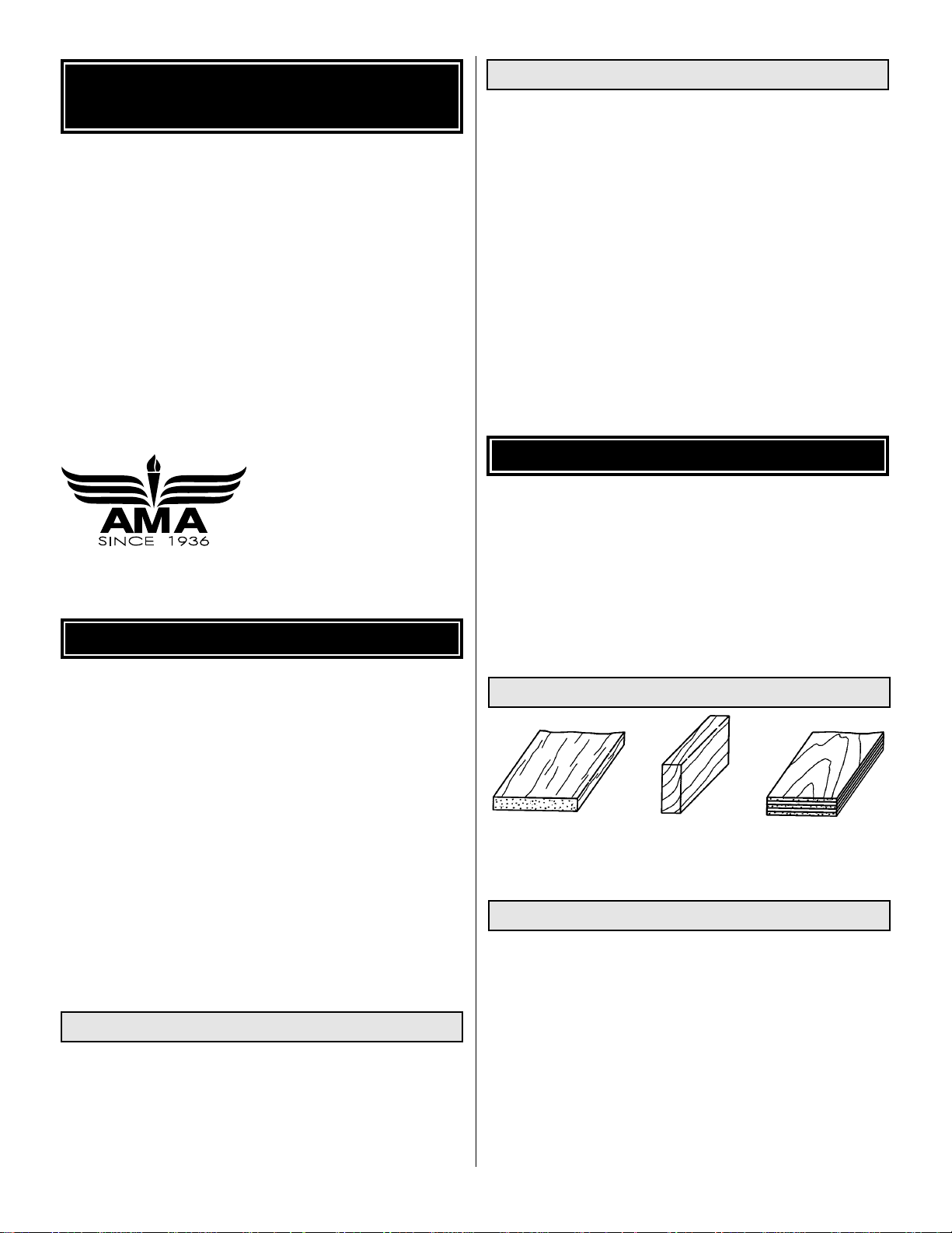
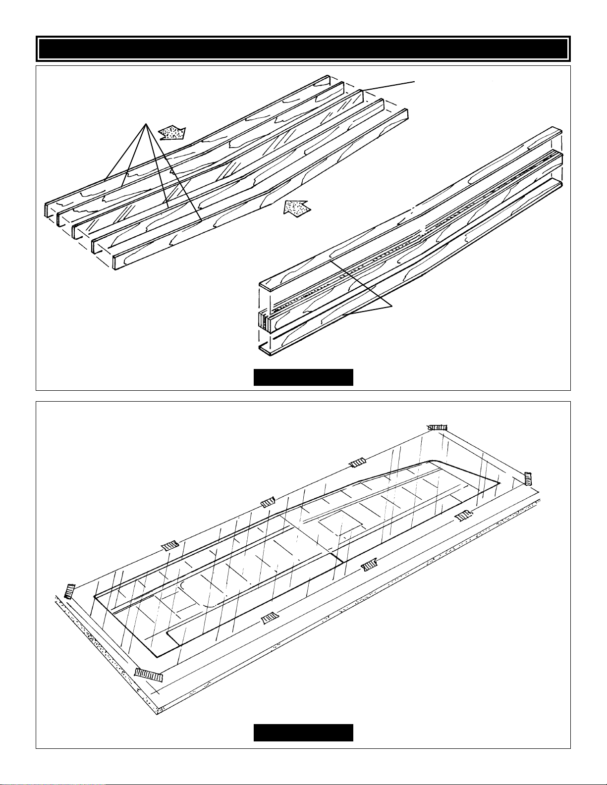
BALSA BASSWOOD PLYWOOD
1. Unroll the plan sheet. Reroll the plan inside out and let it
uncurl. This will help the plan lie flat.
2. Remove all parts from the box. Identify each part by
comparing it with the plan, parts list and die-cut parts page.
Write the part number or size on each piece to avoid
confusion later. Use the die-cut patterns shown on page 3
to identify and mark the die-cut parts.
3. If any of the die-cut parts are difficult to remove, use a
hobby knife to free them. Use your sanding block to lightly
sand the edges to remove any die-cutting irregularities.
Get Ready to Build
Types of Wood
WING OPTIONS
Supplies & Tools Needed
Other Items Required
INTRODUCTION
PROTECT YOUR MODEL,
YOURSELF & OTHERS
2
Page 3
3
DIE-CUT PATTERNS
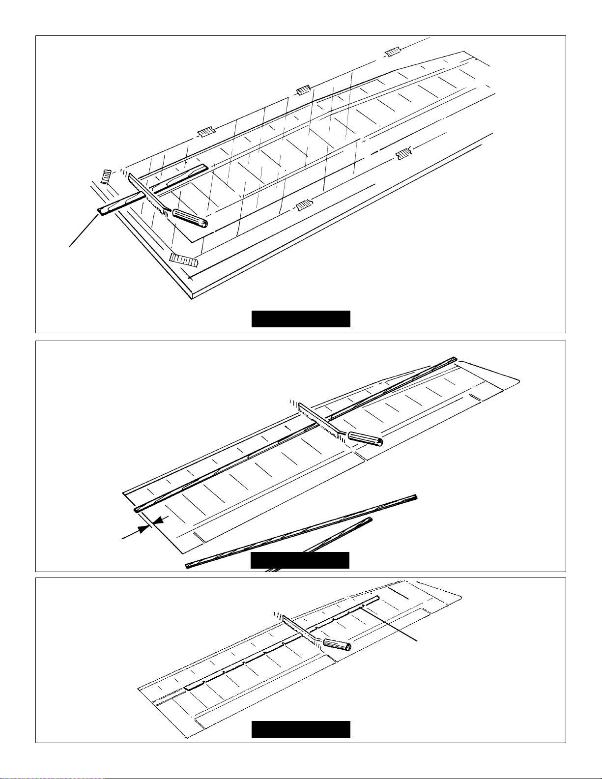
Page 4
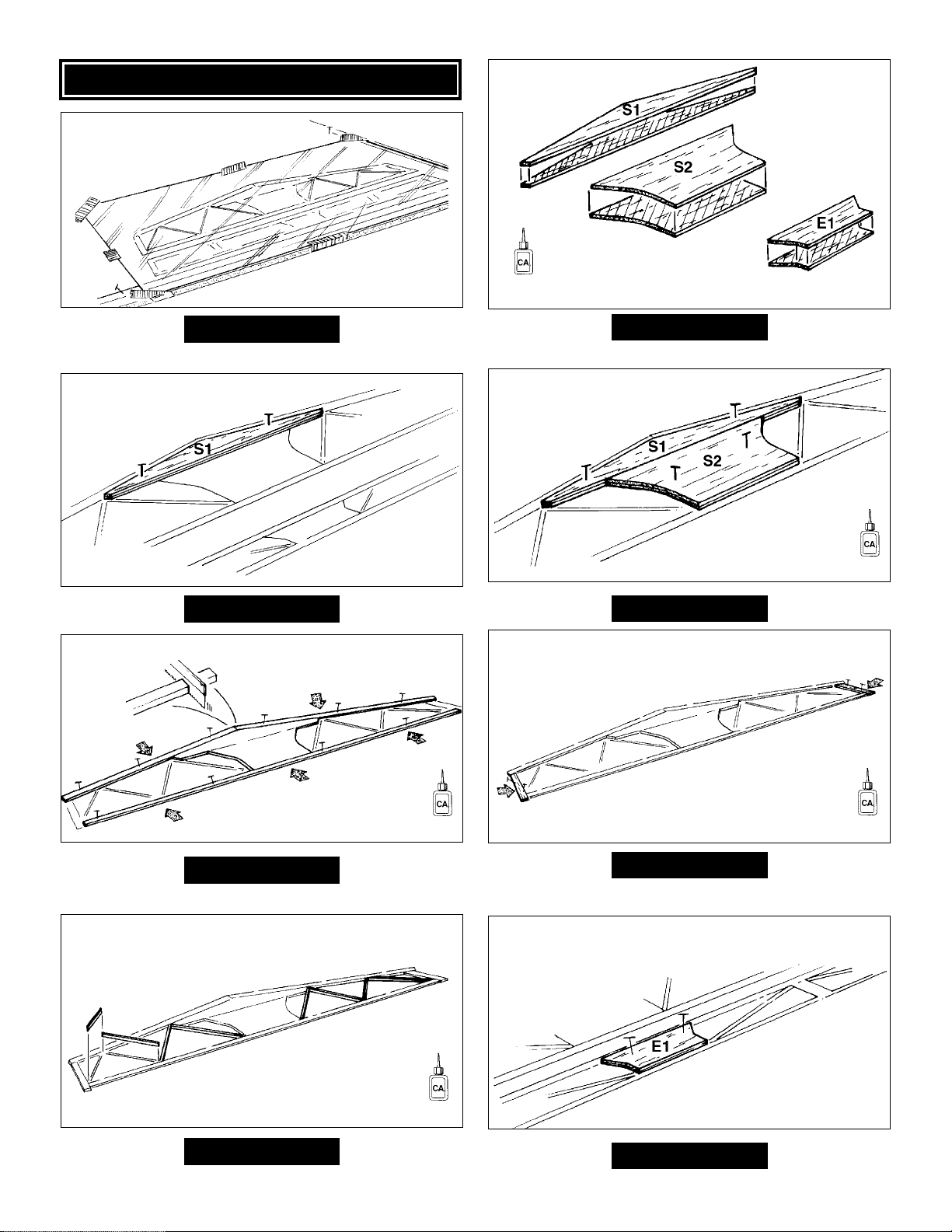
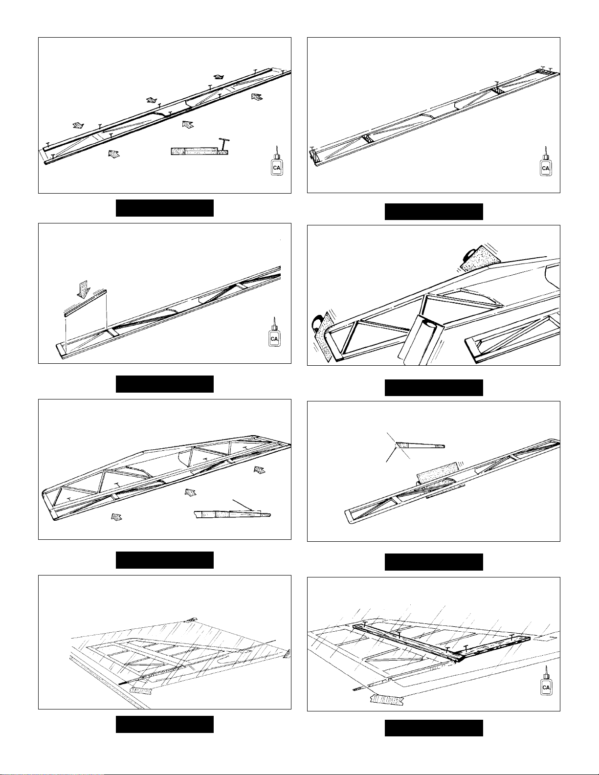
Step 8
Step 6
Step 4
Step 2
Step 7
Step 5
Step 3
Step 1
ASSEMBLE THE TAIL
4
Cover the stabilizer and elevator
plan with Great Planes Plan
Protector or wax paper.
Medium
(When you see this symbol use the suggested CA.)
(When you see this symbol use the suggested CA.)
Thin
Thin
Thin
Thin
Page 5
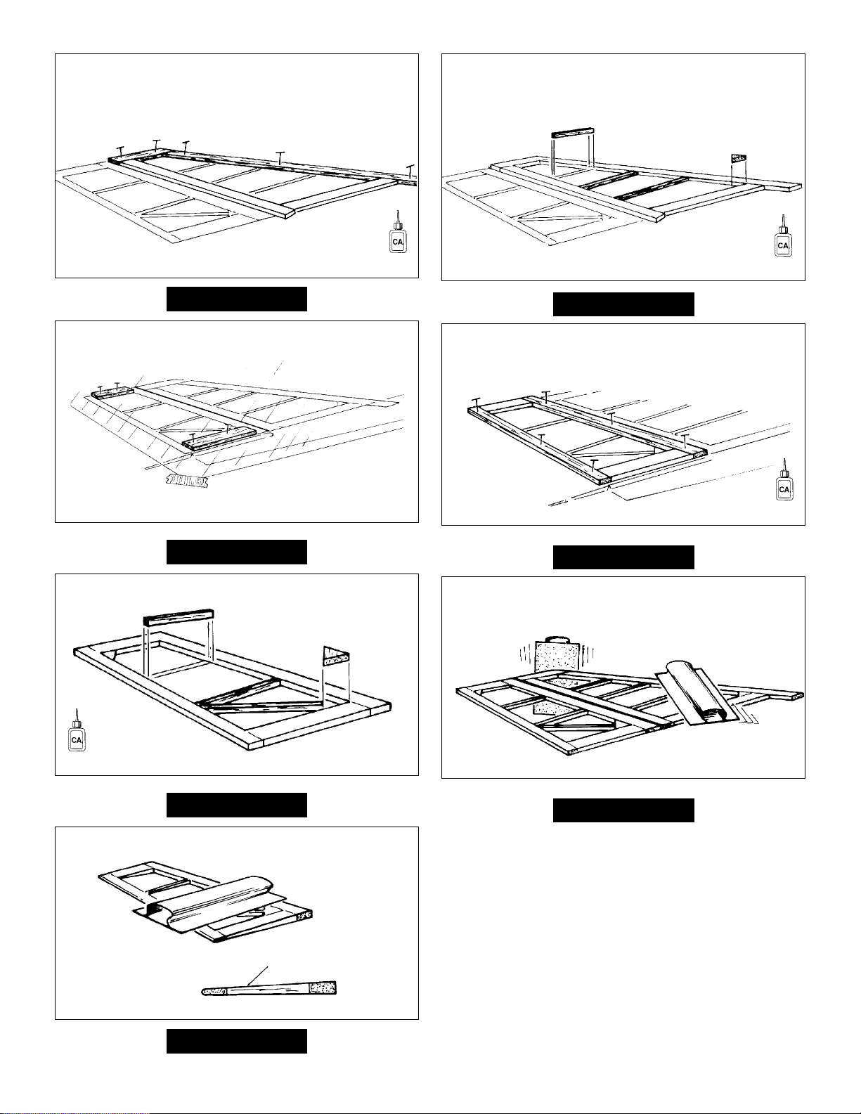
Step 16
Step 14
Step 12
Step 10
Step 15
Step 13
Step 11
Step 9
5
Thin
Thin
Thin
Thin
LE
SAND THE
ELEVATOR
BEVEL THE
LEADING EDGE (LE)
TE
Sand the stabilizer smooth. Round
the leading edge (LE) and tips.
Cover the fin and rudder plan with
Great Planes Plan Protector or
wax paper.
Page 6
Step 22
Step 20
Step 18
Step 23
Step 21
Step 19
Step 17
6
Thin
Thin
Thin
Thin
Sand the fin and rudder smooth.
Round the LE of the fin.
SAND THE RUDDER TO A TAPER
Page 7
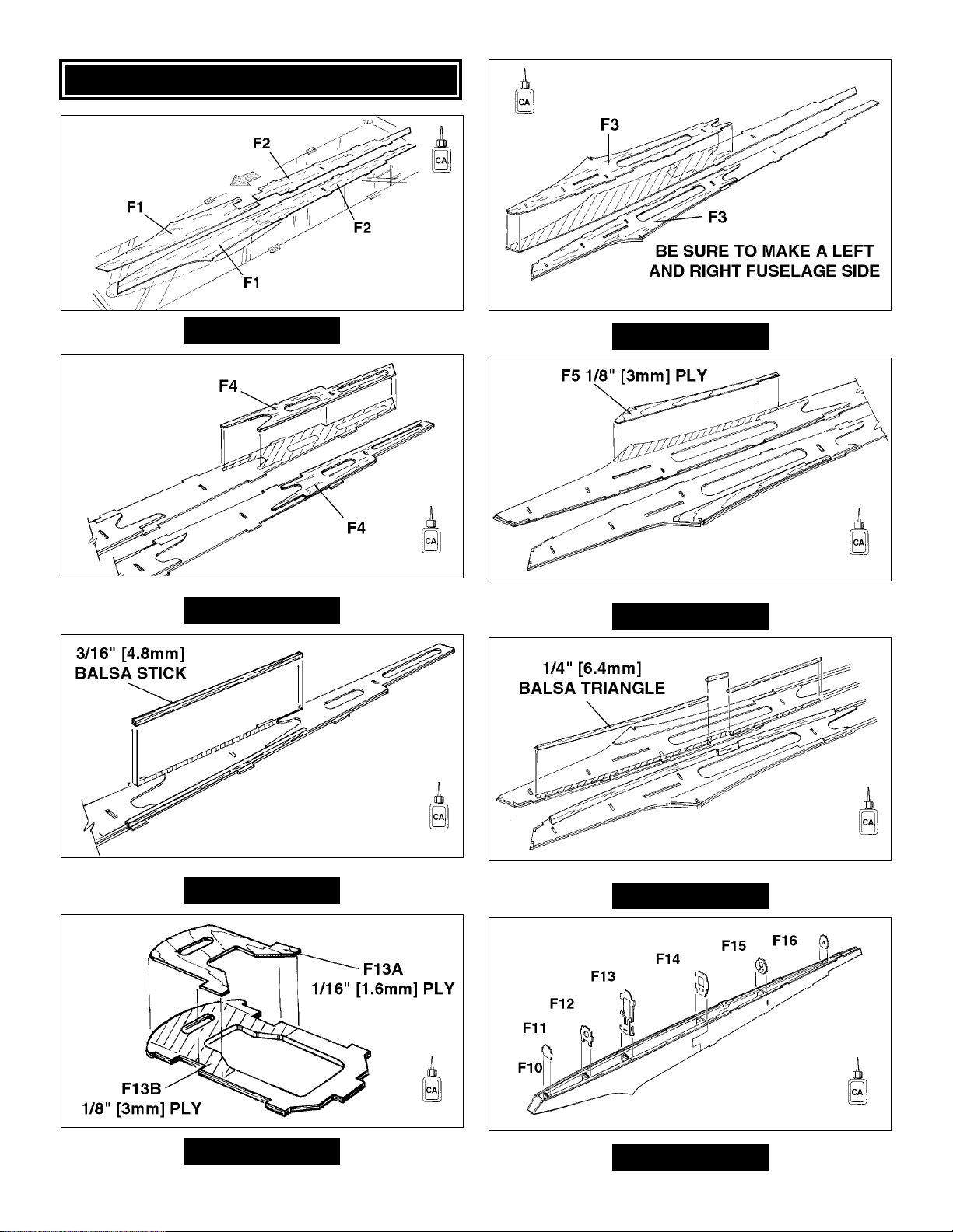
Step 8
Step 6
Step 4
Step 2
Step 7
Step 5
Step 3
Step 1
ASSEMBLE THE FUSELAGE
7
Make sure the pushrod tubes
fit easily into the guide holes
before installing
the formers.
Use rubber bands to
hold everything together.
Thin
Thin
Thin
Medium
Medium
Medium
Medium
Medium
Make sure the fuselage
lines up straight.
Cover the fuselage plan with
Great Planes Plan Protector
or wax paper.
Page 8
Step 16
Step 14
Step 12
Step 10
Step 15
Step 13
Step 11
Step 9
8
Make sure the three punch
marks on F9, face the inside
of the fuselage.
Use rubber bands to hold the
fuselage together. Make sure
the fuselage is straight and
then glue.
Thin
Thin
Thin
Medium
Medium
Make sure the fuselage
is straight before gluing.
Sand entire fuselage smooth.
Round corners as shown on plan.
Trim off excess.
Slide in from back.
Page 9
9
Glue and clamp the wing joiner
together using 30-minute epoxy.
Wipe off any excess epoxy before
it cures.
Cover the wing plan with
Great Planes Plan Protector
or wax paper.
1/16" [1.6mm] PLY
WING JOINERS
1/16" [1.6mm] PLY
JOINER CAPS
ALUMINUM JOINER
(Clean with alcohol)
Step 1
Step 2
BUILD THE WING
Page 10
10
1/8" [3.2mm ]
PLY JOINER BOX
W23
Step 3
Step 4
Step 5
Cut the 1/8" x 3/4" x 12-1/2"
[3.2mm x 19mm x 317mm]
plywood to make the joiner
box parts
Position the 1/8" x 5/16" x 40"
[3.2mm x 8mm x 1016mm]
spars over the plan.
Cut the spars at rib 9.
Leave
1/4" [6.4mm]
overhang.
Cut the W23 balsa
shear web at rib 9.
Page 11

11
SPAR
W8
W7
W6
W5
W4
W23
3/16" [4.8mm] SQUARE
BALSA RIB JIGS
W2A
W2B
W3B
W3A
1/8" [3.2mm] JOINER
BOX FRONT
1/8" [3.2mm] JOINER
BOX AFT
Step 6
Step 7
Step 8
Shim the spar up from the
table using 1/16" [1.6mm]
balsa. (Use leftover pieces
from the rib die sheets.)
Use pieces of the 3/16" x 3/16"
balsa sticks as rib jigs to hold
the ribs in place for the steps
that follow.
Clamp the 1/8" [3.2mm] joiner
box front and joiner box aft to
the spars.
Add ribs 2A&B.
Add ribs 3A&B.
BUILD THE
INBOARD PANEL
Thin
DO NOT GLUE THE
JOINER BOX YET!
Page 12

12
70%
ISOPROPYL
ALCOHOL
Step 10
Use 30-minute epoxy to glue the
joiner box to the spars.
Before the glue cures, insert the
wing joiner several times to get a
good fit and to push out excess
glue. When satisfied, pull out the
joiner and wipe clean.
Coat the wing joiner with
isopropyl alcohol so the
epoxy won't stick.
DGR
DGR
W1B
W1A
Align the rib between the
dashed lines on the plan.
Align the rib between the
dashed lines on the plan.
Use the dihedral gauge to
set the angle.
1/16" X 3/8" X 42"
[1.6mm X 9.5mm X 1067mm]
SUB LE
1/8" X 1/2" X 42"
[3.2mm X 12.7mm X 1067mm]
BALSA WING TE
Step 9
Center the TE on the ribs.
Line up the LE.
Step 11 Step 12
Thin
Thin Thin
Page 13

13
1/16" X 3" X 24"
[1.6mm X 76mm X 610mm]
BALSA SHEET
1/16" X 3/8" X 42"
[1.6mm X 9.5mm X 1067mm]
BALSA TE SHEETING
Step 15
The sheeting should line up
with the back edge of the spar.
Make sure the structure stays
flat on the table.
Fill in any gaps with
1/16" [1.6mm] balsa.
Sand the sheeting
so it doesn’t bulge
at the cloth.
3/16" X 3/8" X 5-1/2"
[4.8mm X 9.5mm X 140mm]
BASSWOOD RAILS
2-3/4" [70mm]
2-3/4" [70mm]
Step 16
DGP
W9B
W9A
FIBERGLASS
CLOTH
POLYHEDRAL WING
Use the polyhedral gauge
only if you are building
the polyhedral wing.
Cut the fiberglass cloth into four 4” [100mm] pieces.
Attach part of the fiberglass cloth to the spars
using thin CA. You will finish this
step after you remove the
panel from the table.
STRAIGHT WING
Align ribs W9A and W9B
straight up and down
over the plan.
Step 13 Step 14
Thin
Thin
Medium
or
aliphatic
wood
glue
Medium
Cut the rails in half.
Page 14

14
1/16" X 3" X 24"
[1.6mm X 76mm X 610mm]
BALSA SHEET
W20 1/16" [1.6mm]
PLY HATCH
Step 17
Use the ply hatch as a
template for cutting the
hole for the flap servo.
Cut from 1/16" X 3" X 24"
[1.6mm X 76mm X 610mm]
BALSA SHEET
Step 18
Step 19
Remove the wing from the
table. Cut off the jig tabs
and sand smooth.
Step 20
Wrap the fiberglass cloth tightly around the joiner
box and glue it in place. Cut off any excess.
1/16" X 3" X 24"
[1.6mm X 76mm X 610mm]
BALSA SHEET
Step 21
Glue the top sheeting in place.
1/16" X 3/8" X 42"
[1.6mm X 9.5mm X 1067mm]
BALSA SHEETING
Medium
Medium
Thin
Medium
or
aliphatic
wood
glue
The cloth will cause the
sheeting to bulge. sand the
sheeting to compensate.
Page 15

15
1/16" X 3" X 24"
[1.6mm X 76mm X 610mm]
BALSA SHEET
Step 22
Install the top center sheeting.
Step 23
Sand the root and the
outer ribs smooth.
Bevel the leading edge so the balsa
will follow the shape of the rib.
Cut 2-1/2" [63.5mm] from one of the 1-3/4" x 24"
[44.4mm x 610mm] balsa triangles and glue in
place at the wing root.
Trim off and sand the leading
edge smooth.
Finish the slot in W1A
for the wing dowel.
Epoxy the wing
dowel and W1C
to the wing root.
Step 24 Step 25
Medium
Page 16

16
Step 26
Cut the spars straight with rib 9.
Position the 1/8" [3.2mm]
spars over the plan.
1/8" [3.2mm]
BUILD THE
OUTER PANEL
Step 27
W11
W10
W23
W12
W13
W14
W15
W16
1/16" [1.6mm]
SHIMS
Make rib jigs from
the 3/16" [4.8mm]
square sticks.
Step 28 Step 29
1/16" X 3/8" X 42" [1.6mm X 9.5mm X 1067mm]
BALSA LE
(Left over from the inner panel.)
1/8" X 1/2" X 42" [1.6mm X 9.5mm X 1067mm]
BALSA TE
(Left over from the inner panel.)
Thin
Thin
Page 17

17
Step 30
1/16" X 3" X 24"
[1.6mm X 76mm X 610mm]
BALSA SHEETING
1/16" X 3/8" X 42"
[1.6mm X 9.5mm X 1067mm]
BALSA TE SHEETING
1/16" [1.6mm]
PLY HATCH
Install the servo rails.
Cut from 3/16" x 3/8" x 5-1/2" basswood.
Install 1/16" [1.6mm] balsa sheeting
around the servo hatch.
Step 31 Step 32
Step 33
Cut a small gusset from
3/8" [9.5mm] balsa.
Medium
or
aliphatic
wood
glue
Medium
Thin
Thin
Page 18

18
W9A
W9B
Trim excess sheeting.
Step 34 Step 35
1/16" X 3" X 24"
[1.6mm X 76mm X 610mm]
BALSA SHEETING
Step 36
1/16" X 3/8" X 42"
[1.6mm X 9.5mm X 1067mm]
BALSA TE SHEETING
Step 37
Trim off the excess sheeting
and sand smooth.
Sand the root and
tip ribs smooth.
Thin
Page 19

19
Step 38
Join the tip panel to the root panel
using epoxy and the straight
W19 1/16" [1.6mm] ply joiner.
Sand the root and
tip ribs smooth.
W19
STRAIGHT WING
Step 40
Shape the LE as
shown on the plan.
Glue the 1/4" x 7/16" x 42"
[6.4mm x 11mm x 1067mm]
balsa LE to the wing panels.
Step 39
Join the tip panel to the root
panel using epoxy and the
W18 1/16" [1.6mm] ply joiner.
Use the (DGP) gauge
under the W16 rib to
help set the height.
W18
POLYHEDRAL WING
Page 20

20
Bevel the LE so the balsa will
follow the shape of the rib.
Glue and shape the balsa
wing tip to the tip panel.
Cut 2-1/2" [63.5mm] from a
1-3/4" x 24" [44.4mm x 610mm]
balsa triangle.
Step 41 Step 42
1/16" [1.6mm]
PLY WING BOLT
PLATES
Make an aileron and a flap from the leftover
1-3/4" [44.4mm] balsa triangles. Bevel their
leading edges as shown on the plan.
Step 43
Step 44
Drill two 5/32" [4mm] holes
through the wing and into
the fuselage.
Align the wing to the fuselage.
3/4”
[19mm]
7/16”
[11mm]
Step 45 Step 46
AILERON
FLAP
Medium Medium
Medium
Page 21

21
Carefully tap the two holes. Reinforce the
threads with thin CA and retap.
Enlarge the holes
in the wing.
Step 47 Step 48
10-24 TAP
Build the canopy.
Glue the plywood C2 doubler
to C1 balsa canopy base.
Glue the canopy parts
together. Be carful not to
glue them to the fuselage.
Trim and sand C1 and
C3 to fit your
Step 1 Step 2
C1
C1
C3
C4
C2
Drill a 1/8" [3mm] hole into the nose block. Glue in
the 1/8" x 1" [3mm x 25.4mm] dowel into the canopy
base. Do not glue the dowel to the fuselage.
Step 3 Step 4
BALSA NOSE BLOCK
1/8" [3mm]
DRILL BIT
Medium
Thin
Thin
FINISHING
Page 22

22
Trim the plastic canopy to fit the canopy
frame and fuselage.
Sand the nose block to shape.
(See plan)
Step 5 Step 6
Drill 3 holes in F9 - 1/16"
[1.6mm] ply tow hook mount.
Press in the three
blind nuts.
Step 7 Step 8
SMALL
RUBBER
BAND
4-40 TOW
HOOK
CENTERLINE
MARKING
TOOL
4-40
WASHER
4-40 NUT
# 2 X 3/8" [9.5mm] SCREW
1/8" [3mm]
DRILL BIT
Mark a center
line on the fin
and rudder.
Carefully cut hinge
slots at the locations
shown on the plan.
Cut two 3/4" x 1" [19mm x 25.4mm] hinges
from the 2" x 9" [50.5 x 228.5mm] hinge strip.
Step 9 Step 10
HINGE THE RUDDER
Medium
DO NOT
GLUE
YET.
Page 23

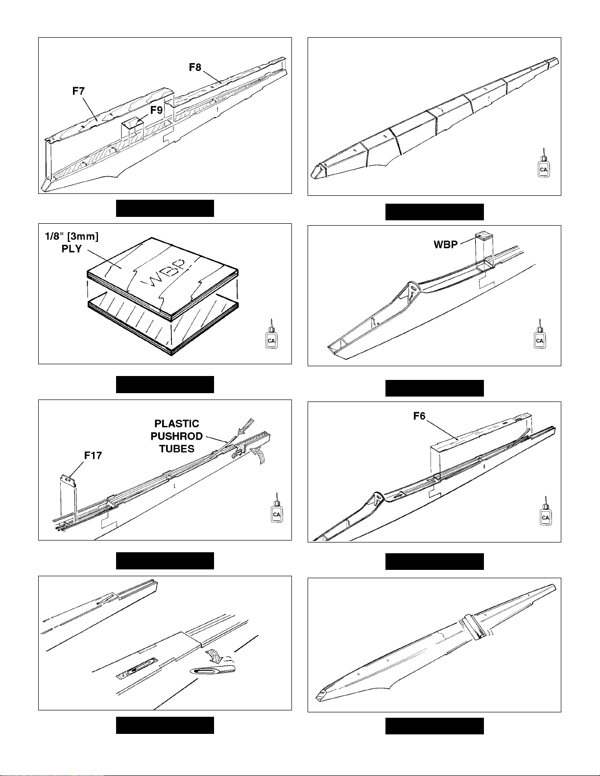
Fuselage and Tail:
1. 1/4” strips at stab as described above
2. Stab bottom
3. Stab Top
4. Fin Left and Right
5. Rudder Left and Right
6. Elevator bottom and top
7. Fuselage bottom
8. Fuselage left and right
9. Fuselage top
Wing:
1. Ailerons and Flaps bottoms and tops
2. Bottom right, followed by the bottom left
wing panel. (If building the polyhedral wing,
cover the inner and outer panels separately.
3. Top right, followed by the left wing panel.
23
Bevel the leading edge
of the rudder as shown
on the plan.
Hold the flaps and ailerons
in place and mark the
locations for the control
horn plate (W22).
Step 11 Step 12
Step 13
Cut out the balsa and
glue in the W22 ply
control horn plate.
The plate should be
flush with the balsa.
Step 14
Preparing The Surface
Most of the model should be rough-sanded by now, with all edges
sanded and rounded following the cross-section views on the
plans. If not, do so now. Fill all dents, seams, low spots and
notches with HobbyLite
™
balsa colored filler. After the filler has
dried, use progressively finer grades of sandpaper to even and
smooth all the edges, seams and surfaces. Remove all the balsa
dust from the model with compressed air or a vacuum with a brush
and a tack cloth.
Covering Technique
Cover the model with Top Flite MonoKote film, using the
suggested covering sequence that follows.
Some modelers prefer to cover the top and bottom of the ailerons
with one strip of MonoKote film. This is done by covering the bottom
first, then wrapping the MonoKote film up over the leading edge.
Apply 1/4” wide strips of MonoKote film in the corners where the
stab and fin meet the fuselage. Proceed to cover the stab with
pre-cut pieces that meet in the corners and overlap the 1/4” strips.
Never cut the covering on the stab and fin after it has been
applied except around the leading and trailing edges and the tips.
Modelers who do this may cut through the covering and into the
wood. This will weaken the structure to a point where it may fail
during flight.
S
UGGESTED COVERING SEQUENCE
COVERING
Medium
Page 24

24
STAB
ELEVATOR
MONOKOTE OR
STRONG TAPE HINGE
Fold back the elevator and
apply monokote or strong
tape to the underside.
Step 17Step 16
Installing CA Hinges for the Rudder
The Rudder in this kit is attached using two CA hinges
where shown on the plans.
It is best to leave a very slight hinge gap, rather than closing it up tight. This will prevent the Glue from wicking along
the hinge line. Insert a small pin through the center of each hinge to keep the hinge centered while you install the
control surfaces.
Step 15
DRILL A 3/32" HOLE
1/2" DEEP, IN CENTER
OF HINGE SLOT
TEMPORARY PIN
TO KEEP HINGE
CENTERED
ASSEMBLE, THEN APPLY 6 DROPS
OF THIN CA TO CENTER
OF HINGE, ON BOTH SIDES
Page 25

25
MONOKOTE OR
STRONG TAPE HINGE
Use a triangle to align the
fin 90
o
to the stab. Glue in
place with epoxy.
Position the fin so it is straight with the
fuselage. Remove the covering where
the fin rests on the fuselage.
Install the flaps and
ailerons with MonoKote
or strong tape hinge.
Step 20Step 19
# 2 X 3/8" [9.5mm]
FLAT HEAD SCREWS
Cut servo blocks from the 3/16" x 3/8" x 2"
[4.8mm x 9.5mm x 50.8mm] basswood.
Drill small pilot
holes for the
servo screws.
Drill pilot holes
for the screws.
Install the servos
to the blocks.
Cover the hatch
with Monokote.
Glue in place
with Medium
CA or epoxy.
Step 22Step 21
A=A AA
AA
A=A
Step 18
Align the stabilizer so that it is parallel
with the wing.
When satisfied with the fit,
glue in place with epoxy.
Page 26

26
Step 24
1" [25.4mm]
THREADED WIRE
INNER PUSHROD TUBE
NYLON CLEVIS AND
CLEVIS RETAINER
Step 25
1" [25.4mm]
THREADED WIRE
METAL CLEVIS
NYLON BACKPLATE
NYLON CONTROL HORN
2-56 X 3/8" [9.5mm] BOLT
2-56 X 3/8" [9.5mm] BOLT
Wrap the receiver and
battery in foam.
Line up the control horns
with the pushrods. Attach
the control horns to the
elevator and rudder.
Install the switch inside the
fuselage, next to the receiver.
Step 23
Page 27

NOTE: This section is VERY important and must not be
omitted! A model that is not properly balanced will be
unstable and possibly unflyable.
1. The balance point (Center of Gravity) is 3-1/4” (82mm)
from the Leading edge. This is the balance point at which
your model should balance for your first flights. Later, you
may wish to shift the balance up to 1/2”(13mm) behind this
point to change the flying characteristics. Moving the CG
forward will add stability but it will decrease the overall
performance of the sailplane. Moving the balance back
makes the model more agile with a lighter and snappier
“feel” and improves the sailplane’s response to air currents.
However, it will also make the model less stable and can
cause the sailplane to “tuck under” or dive when its flying
speed increases.
2. With the wing attached to the fuse, and all parts of the
model installed (ready to fly), lift the model by picking it up
with your fingertips. If the tail drops when you lift, the model
is “tail heavy” and you must add weight to the nose to
balance. If the nose drops, it is “nose heavy” and you must
add weight to the tail to balance. The model should hang with
a slight nose down attitude. Add BB’s or lead to the nose.
1. The tow hook should be in the front hole for the first
flights. After the first flights the tow hook can be moved back
to the middle hole for most flying conditions. For contest
flying you may want to try the rear hole as it can help
achieve a higher launch. But be careful as the sailplane will
be less stable and more apt to “Pop Off’ the line.
If you are not thoroughly familiar with the operation of R/C
models, ask an experienced modeler to check to see you
have the radio installed correctly and all the control surfaces
do what they are supposed to.
TRIMMING FLIGHTS
It is a good idea to do a couple of trim flights before each
flying session to make sure the plane is still in trim and the
radio is working properly.
Hold the SPIRIT ELITE under the wing with the nose
pointed slightly down and directly into the wind. Launch the
model with the wings level and the nose pointing at a spot
on the ground about 50 feet in front of you. If the sailplane
is launched with the nose up or launched too hard it will
climb a few feet, stall and fall nose first straight down. With
the nose pointed down slightly the sailplane will accelerate
down until it picks up enough flying speed, then level off and
glide forward. Adjust the trims on your transmitter to get the
plane to fly straight ahead in a smooth glide path.
FLYING
TOW HOOK LOCATION
Use these control throws for your first flights.
ELEVATOR: 1/2” (13mm)
RUDDER: 2” (50mm)
FLAPS: 1-3/8” (35mm) down
AILERONS: 3/4” (19mm) up, 3/8”(9.5mm) down
CONTROL SURFACE THROWS
BALANCE THE MODEL
27
Page 28

HI-START LAUNCH
A hi-start is the most common way to launch your SPIRIT
ELITE. Follow the directions that came with the hi-start and
lay it out directly into the wind. Place the stake at the far
upwind edge of the flying field so the parachute will blow
back onto the flying field.
Hook the parachute up to the tow hook. Pull the plane back
approximately twice as far as the rubber is long or whatever
the hi-start instructions recommend.
Hold the plane above your head with the wings level and the
nose pointed slightly up and directly into the wind. Give the
plane a push forward to get it flying and it will climb up like
a kite. You should not have to touch the elevator during the
launch. Use the rudder stick to keep it going straight up.
You will find the ailerons are not very responsive during the
first part of the launch. As the rubber relaxes the plane will
fly off the hi-start.
FIRST FLIGHTS
Use these flights to get the “feel” of the controls and the
SPIRIT ELITE’S flying characteristics. Adjust the trims on
your transmitter (a little at a time) until the plane will fly
straight and level with the transmitter sticks in their neutral
positions. If you built the polyhedral wing, rudder alone is
enough to perform smooth turns. If you built the straight
wing, you will need to coordinate ailerons with rudder for
smooth turns.
The SPIRIT ELITE is a very gentle plane that flys well in
light to moderate winds. Practice coordinating ailerons and
rudder until you can get a tight turn that is relatively flat.
Bank the sailplane with rudder and ailerons first, then add
elevator to pull it around. When setting up to land, point the
nose into the wind just downwind of where you want to land.
Line up with your landing spot and slowly feed in flaps (or
Crow). Add more or less flaps to control your descent angle
and speed so you end up hitting the spot.
There are several types of mixing the Spirit Elite can take
advantage of if you have a “computer radio”.
Launch Camber: Lowering the flaps and ailerons during the
launch will produce a steeper climb giving you better altitude.
A good place to start is about 15 degrees of flap and 5
degrees of aileron drop (The flaps will drop about three times
more than the ailerons). This automatically puts some
washout in the wing which adds stability for arrow straight
launches. If you don’t have a switch for launch camber, just
use the flaps for launch.
Crow: This is used to lose altitude quickly and to control your
glide for spot landings. This mixing is tied to the flap stick
(throttle)and allows the ailerons to come up as the flaps drop.
Be sure to use plenty of aileron differential when using
CROW mixing because the ailerons become less effective at
very high angles of deflection. Also use maximum rudder
coupling at full CROW. If you don’t have CROW capabilities
just use flaps and make sure you have full rudder throw when
the flaps start coming down. It is a good idea to get lined up
on the spot before dropping the flaps very much because the
rudder will become sluggish with the flaps down at slow
speeds. Note: You will need to mix in a little down elevator
with the flaps to keep the plane tracking straight.
Aileron/Rudder Coupling - This is used to allow the
sailplane to make efficient, non-slipping, non-skidding turns.
You will need to experiment to find the proper amount of
throw required to do this but 1” (25mm) of rudder throw at full
aileron is probably a good place to start.
Elevator/Camber Coupling - This is a neat type of mixing
allows the TE (ailerons and flaps) to respond to the elevator.
When properly set up, this can be very useful when floating
around in light air or when trying to thermal very tightly. This
mixing can change the flying characteristics of the plane so
start off small and get used it. A good place to start would be
1/8” (3mm) of TE drop at full up elevator.
Controlling the Wing Trailing Edge (Camber): The wing
camber is usually controlled by a 3-position switch. The traditional
way of setting this switch is to have: the middle position set to
neutral camber, one direction for reflex (the entire TE raises about
1/16”( 1.5mm)) and the other direction for positive camber (the
entire TE drops about 3/32”(2.5mm)). This way of programming
the switch is great for good thermal-days or days with a lot of wind
where you might need the reflex capability for zooming up wind.
The other way we set this switch is to have the “back” position for
neutral camber, the middle position for a slight amount of positive
camber (1/32”(1mm) - 1/16”(2mm)), and the forward position for
more positive camber (3/32”2.5mm - 1/8”(3mm)). The middle
position can be used once good air is located or when trying to
gain a few extra seconds of air time. Normally the L/D will not be
as great as neutral camber but the sailplane will float better. The
forward position is when the sailplane is low and encounters lift,
don’t panic, just hit the switch. The SPIRIT ELITE will really slow
up and will thermal “on a dime”. This set-up is great for duration
type flying without a lot of wind.
ADVANCED FEATURES
28
Page 29

Thermals are a natural phenomenon that happen outside,
by the millions, every single day of the year. Thermals are
responsible for many things including forming several types
of clouds, creating breezes, and distributing plant seeds and
pollen. If you have ever seen a dust devil (which is nothing
more than a thermal that has picked up dust), you have
seen a thermal in action. Their swirling action is very similar
to that of a tornado but much gentler. Most thermals have
updrafts rising 200-700 feet per minute but have been
known to produce updrafts of over 5,000 feet per minute
These strong thermals can rip a plane apart or carry the
plane out of sight before the pilot can get out of the updraft.
Thermals are formed by the uneven heating of the earth and
buildings, etc. by the sun. The darker colored surfaces
absorb heat faster than the lighter colors which reflect a
great deal of the sun’s energy back into space. These
darker areas (plowed fields, asphalt parking lots, tar roofs,
etc.) get warmer than the lighter areas (lakes, grassy fields,
forests, etc.). This causes the air above the darker areas to
be warmer than the air over the lighter areas and the more
buoyant warm air rises as the cooler, denser air forces its
way underneath the warmer air. As this warm air is forced
upward it contacts the cooler air of the higher altitudes and
this larger temperature difference makes the thermal rise
quicker. The thermal is gradually cooled by the surrounding
cooler air and its strength diminishes. Eventually the
thermal stops rising and any moisture contained in the once
warm air condenses and forms a puffy cumulus cloud.
These clouds, which mark the tops of thermals, are usually
between 2000 and 5000 feet high.
As the glider approaches a thermal, the wing tip that
reaches the rising air first will be lifted before the opposite
wing tip. This causes the plane to “bank” and turn away from
where we would like the plane to go. The best way to get
back in is to continue the bank and turn 270 degrees
straight into the thermal.
When you are thermal soaring, try to fly as smoothly and
straight as possible. Trim the plane to fly in a straight line
and only touch the controls when you have to. Watch the
sailplane carefully and it will tell you what it is encountering.
When the sailplane flys directly into a thermal it will either
start rising or stop sinking. Either case is reason enough to
start circling. Fly straight until you feel like you are in the
strongest lift, then fly a couple of seconds farther so your
circle will be centered in the strongest lift. Thermals travel
with the wind, so be careful that you don’t get too far
downwind that you can’t get back. If you find yourself getting
too high, don’t dive the plane to get out of the lift. Sailplanes
are very efficient aircraft and they will build up a lot of speed
and could “blow up” in the rough air of a thermal. The
easiest way to lose altitude is to apply full rudder and full up
elevator. This will put the plane into a tight spin that will not
over stress the airframe but it will enable it to lose altitude
very quickly. This is especially helpful if the sailplane gets
sucked into a cloud or it gets too high to see.
As you might expect, with all this air rising, there is also air
sinking. This air is the sailplane pilot’s nightmare that can
really make soaring challenging. “Sink” is usually not as
strong as the thermals in the same area but sometimes can
be. Because of this, it is important you do not let the
sailplane get too far downwind.
Watch the birds! - Thermals suck up small insects many
birds love to eat. A bunch of swallows flying around in one
area may indicate a thermal. Soaring birds (hawks, vultures,
eagles etc.) are the best thermal indicators. They not only
show you where the thermal is but they also show you
where the center is. These “Masters of the sky” will often fly
right along with sailplanes.
Practice those landings! - Most thermal contests are won
or lost during the landing. Establish a particular landing
pattern and try to stick to it for all landings. Learn to shift
your pattern to account for the wind and particular flying
field characteristics. Flaps can be very useful during contest
landings. They allow you to bring the sailplane in for a
landing higher or faster than normal to guard against any
last minute sink or gusts and dump the extra altitude and
speed at the last second. They can also be used to help
THERMAL SOARINGFACTS ABOUT THERMALS
29
Page 30

control your skid. Flaps will stop the plane from sliding a
little quicker. You can also “steer” the plane while it is sliding
along the ground. Don’t expect to be able to “horse it
around” but you can gain valuable inches by using the
rudder to guide it towards the spot as it slides to a stop. Be
very careful not to “ground loop” the plane since you will
lose your landing points if the plane flips over.
To be able to slope soar, you need a slope with a smooth
piece of land (or water) out in front of it and a breeze
blowing pretty close to straight up the slope. The higher and
steeper the hill or cliff the better. Also the larger and
smoother the land out in front the better. The air flowing
towards the hill, is forced up and can generate a very large
area of lift. Behind the hill is a large area of turbulent air that
can be very dangerous to try to fly in. The faster the wind is
blowing the stronger the lift and turbulence will be.
To fly off a slope, stand near the edge and throw the
sailplane (nose down) into the wind. As the sailplane flys out
into the “band” of lift it will begin to gain altitude. Turn and fly
parallel to the slope and make all of your turns into the wind
(especially when you are close to the slope). You will be
surprised at the altitude you can gain just from slope lift.
Thermals will often be “popped loose” by these slopes. If
you catch a thermal and follow it downwind, be very careful
to stay high enough to make it back to the slope without
flying through the turbulent air. Landings can be very tricky
on some slopes. On gentle slopes you can often fly very
close to the top of the slope and “slide” into the top of the
slope without encountering any turbulent air. On steeper
slopes you may have to be a little more aggressive to get
the plane out of the lift. In any case it is a good idea to plan
your landing before you launch your plane.
In strong wind conditions, you may want to add ballast
(weight) to the sailplane to increase its wing loading which
increases its normal flying speed. Increasing the weight of
your sailplane does not change its “glide ratio” but it does
make it fly faster which makes it sink a proportional amount
faster. Because of this faster sink rate, you need to be very
cautious when ballasting for a thermal contest. In duration
type contests only use ballast on very windy days that also
have a lot of thermal activity. Center the weight directly on
the center of gravity of the plane so you can add ballast
without having to re-balance the plane. When learning to
ballast your plane, start out small and work your way up.
Have fun and Good lift!!
BALLAST
SLOPE SOARING
30
Page 31

Spirit™100.
Keep your costs in check and still enjoy high-performance
features with the Great Planes Spirit 100. Interlocking
construction makes it beginner-easy to build. Two wing
options—the proven Spirit wing with S-3010 airfoil, or an
advanced version with a highly efficient S-7037 airfoil, plus
flaps and ailerons for greater control—enable fliers of all
skill levels to enjoy its versatile performance. The advanced
wing enables experienced sailplane pilots to use crow
mixing and offers complete camber-changing capability for
superior thermalling!
• Huge 100" wingspan for extra-smooth
flight!
• Two wing options in one easy-to-build kit.
• High performance without high cost.
GPMA0550
Wingspan: 100 in (2530mm)
Wing Area: 946 sq in (61 sq dm)
Weight: 3-4 lb (1420-1840g)
Wing Loading: 8-10 oz/sq ft (23-31 g/sq dm)
Fuselage Length: 51.5 in (1310mm)
Requires: 2-4 channel radio with 2-5 servos (use 3-channel
31
Spectra™Electric Sailplane
Electric motor power and a 78.5" span, triple-taper wing with
modified Selig 3010 airfoil give the Spectra outstanding
climbing ability...while the model's clean, aerodynamic
design helps you stretch your soaring times by moving
easily from thermal to thermal. The kit's easy assembly
(using the photo-illustrated manual), durability and forgiving
flight make it great for beginners. Includes hardware,
canopy , molded cockpit, Goldfire 550 motor system and 8x4
prop. Add Great Planes' scimitar style 8x4 Nylon Folding
Propeller (GPMQ1690) to minimize drag.
• A 2-meter electric that climbs from 0-500
feet in 60 seconds!
• Suitable for any skill level, with easy kit
assembly, smooth flight characteristics and a
durable airframe.
• Powered by an included Goldfire
550 motor system.
GPMA0540
Wingspan: 78.5 in (1995mm)
Wing Area: 676 sq in (43.6 sq dm)
Weight: 48-52 oz (1360-1470g)
Wing Loading: 10 oz/sq ft (31 g/sq dm)
Fuselage Length: 38 in (965mm)
Requires: 2-3 channel radio, 6-7 cell battery & charger
Perfect choices for every sailplane pilot.
Their quiet flight keeps your airfield's neighbors happy. Getting into action is clean, quick and easy. And the best reason
of all to fly a Great Planes sailplane? Their performance is awesome—right out of the box!
Extend your airtime indefinitely with a Great Planes sailplane...there's always more as close as the next thermal! Like the
Spirit Elite, the Spirit 100 and Spectra both offer fast, easy assembly , made even more enjoyable by Great Planes' perfectly
interlocking wood parts, photo-illustrated instruction manuals and premium quality hardware. Both include canopy and
molded cockpit.
Page 32

BUILDING NOTES
Kit Purchased Date: _______________________
Where Purchased:_________________________
Date Construction Started: __________________
Date Construction Finished: _________________
Finished Weight: __________________________
Date of First Flight: ________________________
FLIGHT LOG
PRINTED IN USA
 Loading...