

Page 1
INSTRUCTION BOOK
PLEASE READ THROUGH TH I S INSTRUCTION BOOKLET IN ITS ENTIRETY BEFORE BEGINNING
ASSEMBLY. IT CONTAINS IMPORTANT INSTRUCTIONS AND WARNINGS CONCERNING THE ASSEMBLY
AN D U S E OF T HI S MODEL.
WARNING! THIS IS NOT A TOY!
This R/C kit and the model you will build is not a toy! It is capable of serious bodily
harm and property
damage.
IT IS YOUR RESPONSIBILITY AND
YOURS
ALONE - to
build
this kit correctly, properly install all R/C components and to test the model and fl y it only with
experienced, competent help in accordance with all safety standards and common sense as set
down in the Academy of Model Aeronautics Safety Code. It is suggested that you join the AMA
to become properly insured before you attempt to fly this model. IF YOU ARE JUST STARTING R/C MODELING, CONSULT YOUR LOCAL HOBBY SHOP OR WRITE TO THE
ACADEMY OF MODEL AERONAUTICS TO FIND AN EXPERIENCED INSTRUCTOR IN
YOUR AREA.
Academy of Model Aeronautics
5151 Memorial Drive
Muncie, IN 47302
1-800-435-9262
P.O. BOX 788 URBANA, ILLINOIS 61801 217398-8970
Page 2

TABLE OF CONTENTS
INTRODUCTION
Precautions
..................
Other Items Required
Supplies and Tools Needed
Die Patterns
Abbreviations
Types
of
Wood
.............
..........
......
.................
................
...............
3
3
3
3
4
5
5
Decisions you must make now . . . 5
Get Ready to Build
TAIL FEATHERS
Build
the Fin and Rudder
............
.............
.......
5
6
6
Build the Stabilizer and Elevator . 7
Cut the Hinge Slots
...........
8
WING ASSEMBLY ............ 9
Build
the Inner Wing Panel
......
9
Build the Outer Wing Panel ..... 12
Join the Wing Panels
..........
14
Final Wing Assembly .......... 15
FUSELAGE ASSEMBLY
.......
19
Assemble Fuselage Sides ....... 19
Frame-up the Fuselage
Assemble the Canopy
FINAL ASSEMBLY
.........
..........
............
20
23
25
Balance the Airplane Laterally ... 25
Final Sanding
................
25
Covering .................... 25
Checking for Warps
Glue
the Hinges
Mount the
Tail
Assemble Pushrods
...........
..............
Surfaces
........
...........
26
26
27
27
Install Radio Gear
Control Throws
.............
...............
28
29
Install the Spoilers in the Wing . . . 29
Balance the Model
Final Hookups and Checks
............
......
29
30
PRE-FLIGHT ................. 31
Charge the Batteries
Find a Safe Place to Fly
Range Check
Your
...........
........
Radio
.......
31
31
31
Install the Wings .............. 31
AMA Safety Code .............. 31
General
Radio Control
.....................
................
31
31
FLYING ...................... 32
Trim Flights
Your
First Hi-Start Launch
First Flights
.................
......
..................
32
32
33
THERMAL FLYING ........... 33
Facts About Thermals
Thermal Soaring
Pointers for Contest
SLOPE SOARING
..........
..............
Flying
......
.............
33
34
35
35
Flying ...................... 35
Slope Landings ............... 36
POWERED LAUNCHING ...... 36
BALLASTING ................ 36
BUILDING NOTES ............ 36
PARTS LIST .................. 37
CONTEST PRACTICE CHART .. 39
2-VIEW DRAWING ............ 40
Please inspect all parts carefully before starting to build! If any parts are missing, broken or defective, or i f you
have any questions about building or flying this airplane, please call or write us at the address below and we will
be glad to help. If you are calling for replacement parts, please look up the part numbers a nd the kit identification
number (stamped on the end of the kit box) and have them ready when calling. Thank you.
Great Planes Model Mfg., Inc.
P.O.
Box
788
Urbana, IL 61801 (217) 398-8970
2
P.O.BOX
788
URBANA,
ILLINOIS
61801
217398-8970
Page 3

INTRODUCTION
OTHER ITEMS REQUIRED
Congratulations! You are about to enter the exciting
world of silent flight. Soaring offers a freedom that no other
type of flying can offer! It is your knowledge and your
SPIRIT'S flying abilities in a fight against gravity. With a
little practice and some help from mother nature you will be
able to defeat gravity and enjoy flights that can last for hours
and cover many miles at incredible altitudes.
Thank you for purchasing the Great Planes SPIRIT
sailplane. It has been designed to give you many hours of
relaxing flying, and has also been engineered to provide a
truly enjoyable building experience.
PRECAUTIONS
1. You must build the plane according to the plans
and instructions. Do not alter or modify the model as doing
s o may result in a n unsafe or un-flyable model. In a few cases
the plans and instructions may differ slightly from the photos.
In those instances you should assume the plans and w r itten
instructions a r e correct.
2. You must take time t o build straight, true and strong.
3. You must use a proper R/C radio that i s in first class
condition.
4. You must properly install all R/C and other components so that the model operates properly on the ground and
in
the
air.
5. You must test the operation of the model before the first
and each successive flight to insure that all equipment is
operating, and you must make certain that the model has
remained structurally sound. Be sure to check the nylon
clevises often, and replace if they show signs of wear.
6. You must fly the model only with the competent
help of a well experienced R/C pilot if you are not already an
experienced and knowledgeable R/C pilot at th is time.
Note: We, as the kit manufacturer, can provide you
with a top quality kit and great instructions, but
ultimately the quality and "fly-ability" of your
finished model depends on how you build it; therefore, we cannot in an y way guarantee the performance of your completed model, and no representations are expressed or implied as to the performance
or safety of your completed model.
Remember: Take your time and follow direc-
tions to end up with a well-built model that is
straight and true.
Radio having at least 2 channels (a third channel is
required for optional spoilers)
Iron-on Covering Material (2 rolls)
Latex Foam Rubber Padding (1/4" thick)
#64 Rubber B an ds
Hi-start or other Launching Device
BB's or Lead Shot for Balancing
The Optional Spoilers Also Require:
1 - 3/16" x 1/4" x 36" Balsa Stick
2 - 30" Lengths of Braided Fishing Line
2 - 30" Lengths of 1/8" Plastic Tubing
The Optional Bolt-On Wing Also Requires:
1 - Small Sheet of 1/4" Birch Plywood
1 - Small Piece of 1/16" Birch Plywood
SUPPLIES AND TOOLS NEEDED
2 oz. Thin CA Adhesive
2 oz. Medium or Thick CA Adhesive
2.5 oz. 5-Minute Epoxy
Hand or Electric Drill
Drill Bits: 1/16", 5/64", 1/8", 9/64" (13/64" and 17/64"
for Wing Bolt Option)
Sealing Iron
Heat Gun
Razor Saw
Hobby Knife, #11 Blades
Pliers
Screw Drivers
T-Pins
Assorted Rubber Bands
Straightedge
Masking Tape
Cellophane Tape
Vinyl Tape
Sandpaper (coarse, medium, fine grit)*
T-Bar Sanding Block (or similar)
Waxed Paper
Lightweight Balsa Filler
1/4-20 Tap, Tap Wrench (for bolt on wing option)
Dremel Moto Tool or Similar (optional)
*NOTE: On our workbench, we have four 11" TBar sanders, equipped with #50, #80, #100 and
#150-grit sandpaper. This setup is all that is required for almost an y sanding task. We also keep
some #320-grit wet-or-dry sandpaper handy for
finish sanding before covering.
3
Page 4
SPRTFO1
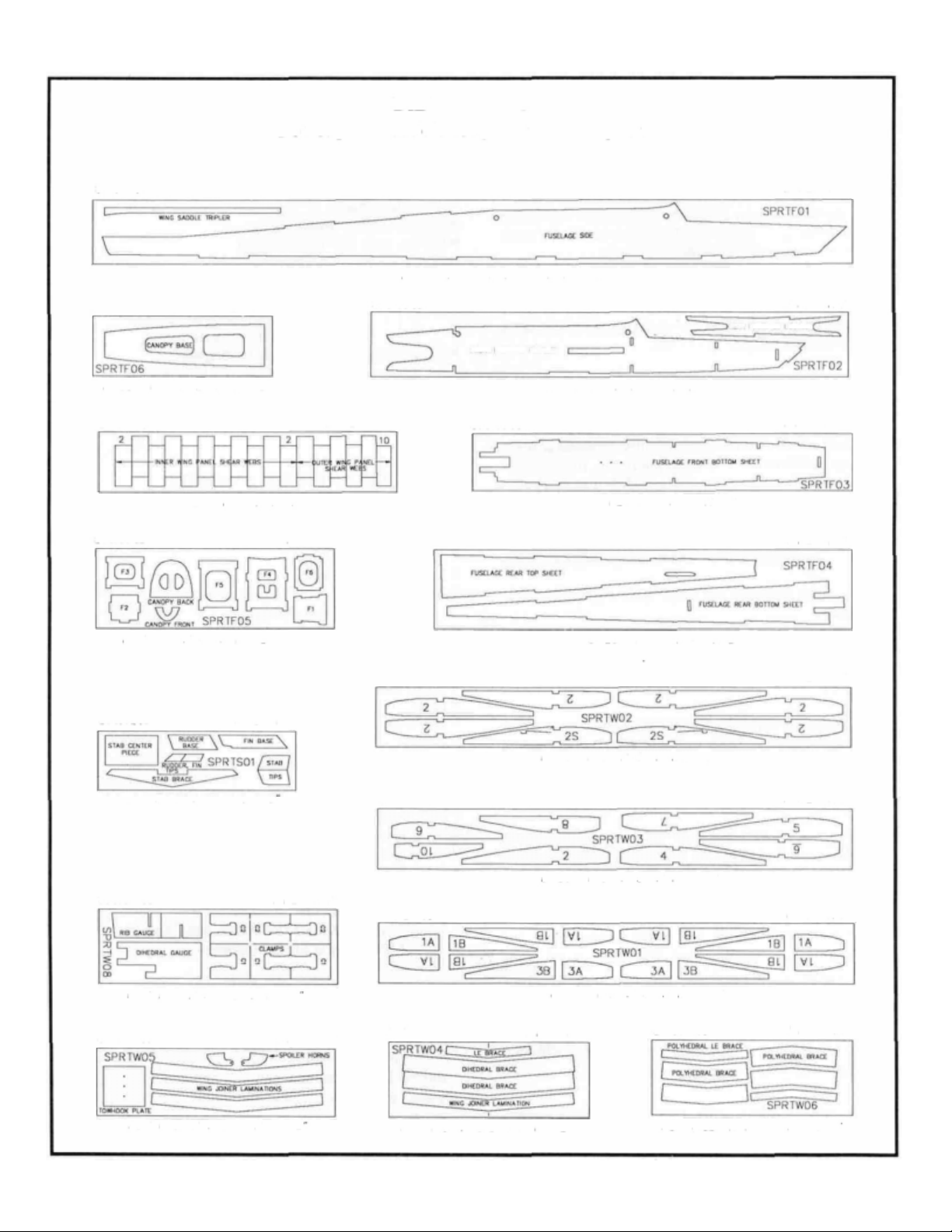
DIE PATTERNS
Do not punch out die-cut parts until ready to use!
BALSA 3/32" X 3-1/4" X 38-1/2"
2
PER
KIT
1
PER
SPRTF06
BALSA 1/8" X 3" X 9-7/8"
SPRTW07
BALSA 1/16" X 3" X 15"
SPRTF05 1 PER KIT
PLY 1/8" X 4" X 11-7/8"
SPRTS01
KIT
1
PER
KIT
2
PER
SPRTF02
KIT
SPRTW02
SPRTF04
FRONT FUSELAGE DOUBLER
BALSA 3/32" X 3-1/4" X 24"
SPRTF03
REAR FUSELAGE DOUBLER
PLY 1/8"
BALSA 3/32" X 4" X 21"
X
3"
X
19"
2
PER
I
PER
I
PER
2
PER
KIT
KIT
KIT
KIT
BALSA 3/16" x 3" x 9-7/8
SPRTW08
PLY 1/8" X 3-7/8" X 11-7/8
SPRTW05
PLY 1/16" X 3-3/8" X 11-7/8
I
PER
1
PER
KIT
KIT
BALSA 1/16" X 3" X 23-7/8"
SPRTW03
BALSA 1/16" X 3" X 23-7/8"
SPRTW01
BALSA 1/8" X 3" X 23-7/8"
SPRTW04 1 PER KIT
PLY 1/8" X 3-3/4 X 10-1/2"
4
2
PER
KIT
I
PER
KIT
SPRTW06 I PER KIT
PLY 1/32" X 3-1/4" X 9-3/4'
Page 5
COMMON ABBREVIATIONS USED IN
THIS BOOK AND ON THE PLANS:
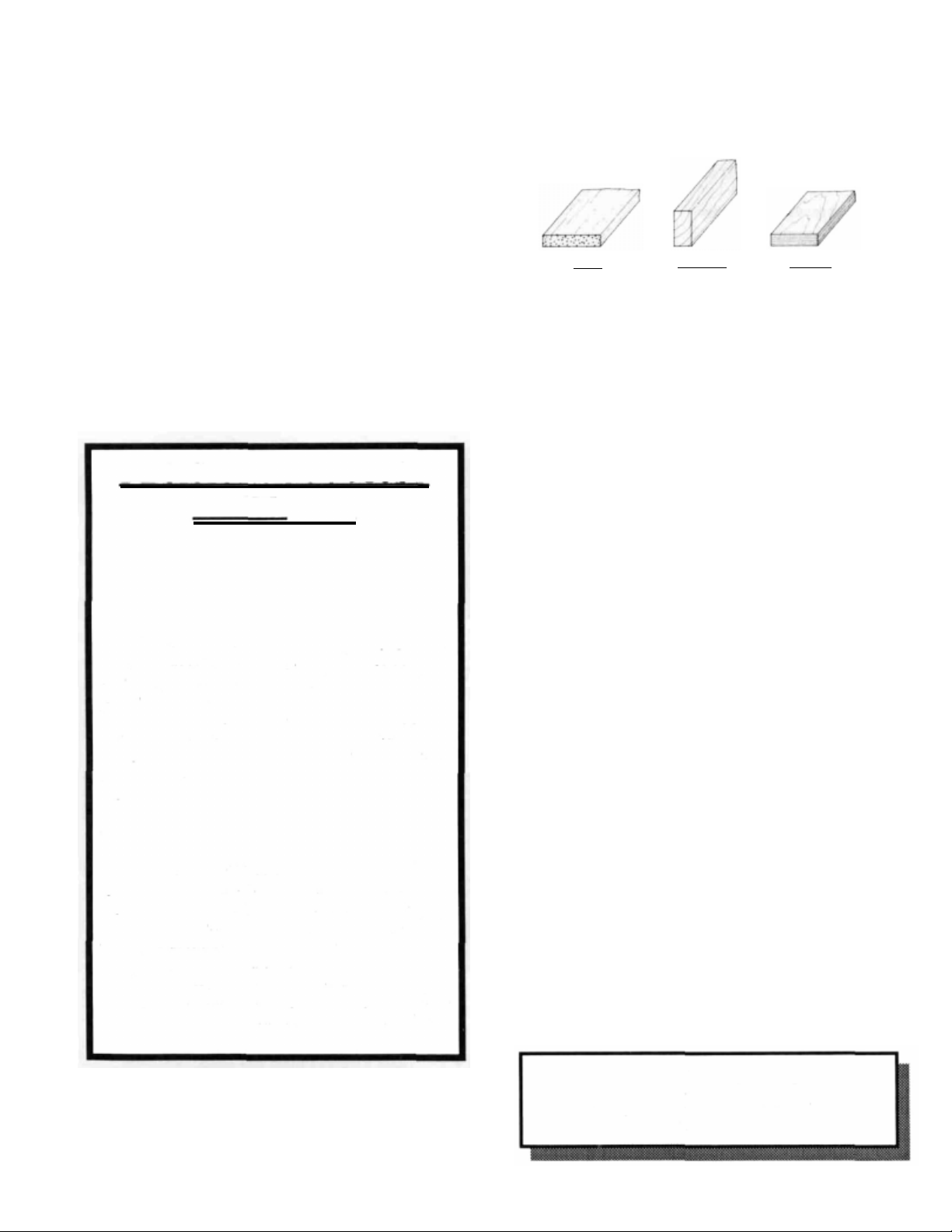
TYPES OF WOOD
Elev
Fuse
LE
Lt
Ply
Rt
Stab
TE
= Elevator
= Fuselage
= Leading Edge (front)
Left
= Plywood
= Right
= Stabilizer
= Trailing Edge (rear)
" = Inches
DECISIONS YOU MUST
MAKE NOW
WING CONFIGURATION
The SPIRIT kit has three different wing options: a
two-piece rubber band on wing, a one-piece bolt on wing
or a one-piece rubber band on wing. The two-piece wing
is the easiest version to build and is recommended for
beginners. Some experienced sailplane pilots may prefer
the one-piece bolt on wing, bu t the large wing can present
transportion problems in todays small cars. The onepiece rubber band wing would be the next best choice for
beginners.
SPOILERS
The SPIRIT can be built either with or without
spoilers. Spoilers act as airbrakes and make it easier for
experienced pilots to precisely land on target during
contests. They can also be helpful in losing altitude
quickly. Due to the added complexity encountered when
installing spoilers, they are NOT recommended for first
time builders. If you a r e a beginner and may eventually
want spoilers, install just the spoiler tubing now and the
rest of the spoiler pans can be installed when you are
ready.
BALSA
BASSWOOD
PLYWOOD
GET READY TO BUILD
NOTE: It will be helpful to build on a piece of
"Celotex", or other semi-soft (and flat) surface,
into which you may easily stick pins to firmly hold
down the parts while building and to avoid warps.
1. Unroll the plan sheet. Re-roll the plan inside out and let
it uncurl while you read through this instruction book. This
will help the plan lay flat and get you acquainted with the
building process. NOTE: Because there are several op-
tions to consider when building the SPIRIT, you should
read the instruction book through before building and
then go back and cross off the steps you won't use to build
your model.
2. Remove all parts from the box. As you do, figure out the
name of each part by comparing it with the plans and the parts
list at the back of this book. Write the part name or size on
each piece to avoid confusion later. Use the die-cut patterns
shown on page 4 to identify the die-cut parts and mark them.
If any of the die-cut parts are difficult to punch out during
construction, do not force them! Instead, first cu t around the
parts with a hobby knife. After punching out the die-cut parts,
use your T-Bar or sanding block to lightly sand the edges to
remove any die-cutting irregularities.
INSTRUCTIONS IN BOXES LIKE THIS
ARE VERY IMPORTANT AND SHOULD
BE FOLLOWED CAREFULLY
5
Page 6
"TAIL FEATHERS"
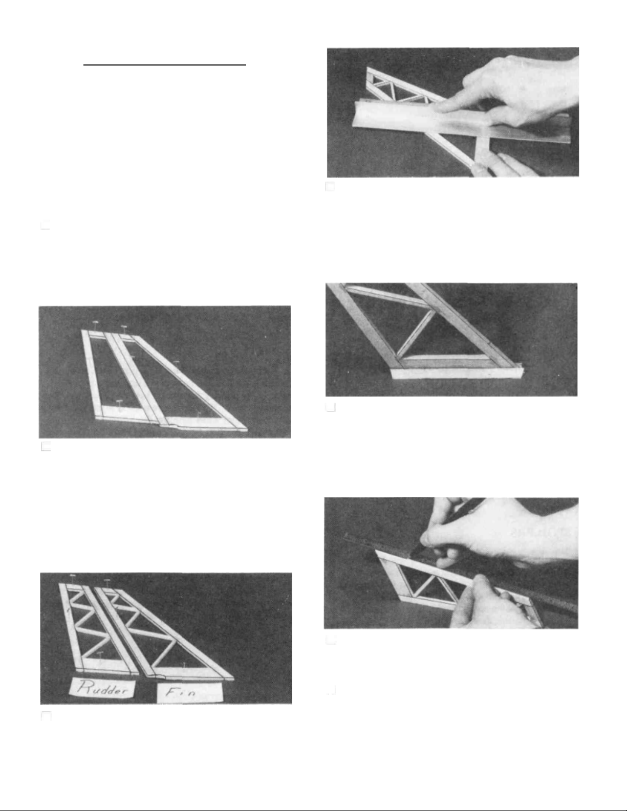
BUILD THE FIN A N D RUDDER
You'll need t he following parts:
SPRTS02 3/16" x 3/8" x 30" Balsa Stick
SPRTS03 1/8" x 3/16" x 30" Balsa Stick
SPRTS01 3/16" Die-Cut Tail Parts
SPRTF08 3/16" Balsa Triangle
D 1 . Tape or pin the plan down to your flat work surface.
Tape a piece of waxed paper over the f i n and rudder portion
of the plan (so you don't glue the parts to the plan).
D 4. Remove the fin and rudder assemblies from the plan
and examine them for any open or bad joints. Fill any gaps
with thick CA, then use your sanding block wi t h me dium grit
sandpaper to sand both sides of t he framework smooth.
D 2. Using the plan as a guide, cut pieces of 3/16" x 3/8"
balsa (from the 30" sticks, SPRTS02) to make the Rudder
and Fin Framework. NOTE: Cu t the Fin L.E., the Rudder
L.E. and the Rudder T.E. from a single SPRTS02 (This wil l
leave enough long pieces for the stab). Punch ou t the die-cut
Fin Tip, Rudder T ip, Fin Base and Rudder Base from
SPRTS01. Sand the edges if necessary and pin them in place
on the plan and glu e the parts together using thin CA glue.
NOTE: Do not glue the fin to the rudder!
D 3. From the 1/8" x 3/16" x 30" sticks (SPRTS03), cu t
the diagonal "ribs" to fit between the rudder and fin frame-
work, and glue them in place. NOTE: It is not necessary to
get these ribs in the exact position shown on the plan.
D 5. Cut two 4-1/8" lengths of 3/16" Balsa Triangle
from SPRTF08 and glue them along the bottom of the fin.
The bottom edges of the tria ngle should be flush with the
bottom of the fin.
D 6. Carefully draw a centerline all around the edges of
the rudder and fin (this will help to maintain symmetry when
sanding).
D 7. Using a sanding block and coarse (50 or 80-grit)
sandpaper, sand the leading edge of the rudder t o the V-shape
as shown on the plans (a small razor plane works great for
initial shaping). Sand the three remaining edges to a smooth
rounded shape. Sand the top and the leading edge of the fin
to a nice rounded shape*. NOTE: The trailing edge of the
6
Page 7
FIN must remain square, do not sand it! Sand the triangle
stock to blend with th e leading and trailing edges of the fin.
Also, cut or sand the bottom of the triangle stock to match the
contour of the 3/16" die-cut fi n bottom.
D 1. Tape waxed paper over the stabilizer drawing on the
plan. In the same manner as the rudder, cut the 3/16" x 3/8"
balsa pieces and using the die-cut Stab Tips, Stab Center
and Stab Brace from SPRTS01, assemble the stab framework using thin CA glue.
D 2. Cut the 1/8 " x 3/ 16" "ribs" to length and glue them
in place.
* MAXIMUM PERFORMANCE TIP - Sand both sides of
the rudder to a taper as shown on the plans. This requires a
little more work but will help to reduce drag and thus increase
performance of the sailplane.
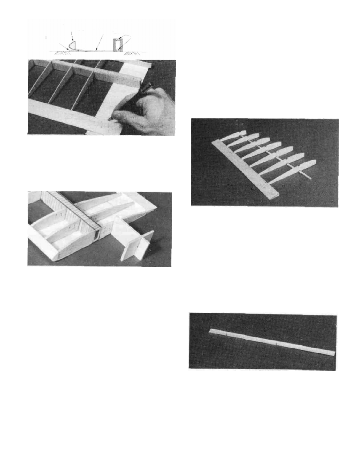
BUILD THE STABILIZER AND ELEVATOR
You'll need the following parts:
SPRTS02 3/16" x 3/8" x 30" Balsa Sticks
SPRTS03 1/8" x 3/16" x 30" Balsa Sticks
SPRTS01 3/16" Die-Cut Tail Parts
SPRTS04 Tapered Elevator
D 3. Pin or tape the elevator (SPRTS04) in place behind
the stab and use your razor saw to cut the ends off t o match the
stab.
D 4. Remove the stab from the plan and examine it for
any open or bad joints. Fill any gaps with thick CA, then use
your sanding block with medium grit sandpaper to sand both
sides smooth. Draw a centerline around the stab edges.
D 5. Tape the elevator to the stab using masking tape and
sand the leading edge of the stab, the stab tips and the elevator
tips to a smooth rounded shape. The tips of the elevator
should blend in nicely with the stab lips.
7
Page 8
D 6. Remove the elevator and draw a center line down its
leading edge. Use yo ur sanding block to sand the same Vshape as you did on the rudder. The trailing edge should also
be sanded to a smooth rounded shape.
D 2. Draw accurate centerlines down the trailing edge of
the stab and the fin. Cut the hinge slots on these lines using
a hobby knife or a slotting fork and slotting hook. (The
recommended hinge slotting technique is listed below).
CUT THE HINGE SLOTS (Do not glue)
NOTE: One-piece molded polypropylene hinges
are supplied in this kit. If you choose to use these
hinges or the "pinned"-type hinges, you may cut
the hinge slots at this time. However, if you choose
to use the one-piece hinges tha t are paper covered
for CA glue installation, you may wait until after
covering before cutting the hinge slots.
A. Begin by carefully cutting a very shallow slit at
the hinge location. This first cut is to establish your cut
in the right place, so concentrate on staying on the
centerline and don't cut too deep!
B. Make three or four more cuts in the same line,
going slightly deeper each time. As you make these
additional cuts, work on going straight into th e wood.
Continue this process while "wiggling" the knife
handle forward and backward until the blade has reached
the proper depth for the hinge.
C. Trial fit the hinge into the slot. If the hinge is
difficult to push in, re-insert the knife and move it back
and forth in the slot a few times to enlarge the slot.
D 3. IMPORTANT! Condition or "break-in" the
hinges by folding them back and forth several times.
D 1. Lay the rudder and elevators on the plan and mark
the hinge locations. Place the rudder against the fin TE and
transfer the marks over to the fin. Place the elevator against
the stab TE and transfer the marks over to the stab.
CAUTION!!!: You must use extreme care when
cutting hinge slots with a hobby knife, to avoid
cutting yourself! If the balsa part breaks while you
are pushing on the knife, the blade could go into
your hand before you know it! A good precaution is
to wear leather gloves while performing the following steps.
D 4. Insert the hinges into the slots and trial fit the rudder
and elevator in place on the fi n and stab. Do not glue the
hinges until after you have covered the model.
8
Page 9
WING ASSEMBLY
BUILD THE INNER WING PANELS
D 4. Carefully punch out all the die-cut 1/16" Balsa W2
and W2S Wing Ribs. Sand the edges slightly to remove any
die-cutting irregularities.
You'll need the following parts:
SPRTW01 1/8" Die-Cut Balsa Wing Ribs
SPRTW02 1/16" Die-Cut Balsa Wing Ribs, W2, W2S
SPRTW03 1/16 " Die-Cut Balsa Wing Ribs, W2, W4-W10
SPRTW04 1/8" Die-Cut Plywood Dihedral Braces
SPRTW07 1/16" Die-Cut Balsa Shear Webs
SPRTW08 1/8" Die-Cut Plywood Clamps and Gauges
SPRTW10 Shaped Balsa Leading Edge
SPRTW 11 Shaped, Notched Balsa Inner Trailing Edge
SPRTW13 1/8" x 5/16" x 23-1/2" Basswood Spars
SPRTW17 1/16" x 3" x 24" Balsa Wing Sheeting
NOTE: The wing is designed to be built as a twopiece wing; however, we also describe how to build
a one-piece wing which can be either held on with
rubber bands or 1/4 - 20 nylon wing bolts (not
included).
D 1. Tape the plan to your flat work surface, and cover
the wing drawing wi th waxed paper. NOTE: If your work
space is limited, you may c ut the wing drawings apart from
the rest of the plans.
NOTE: Follow step 5 below through step 7 on page
15 to build the LEFT wing panel, then repeat these
steps to build the RIGHT wing panel.
DD 5. Pin one of the notched balsa Inner Trailing
Edges (SPRTW 1 1 ) to the plan lining up the notches in the T E
with the notches on the the plan.
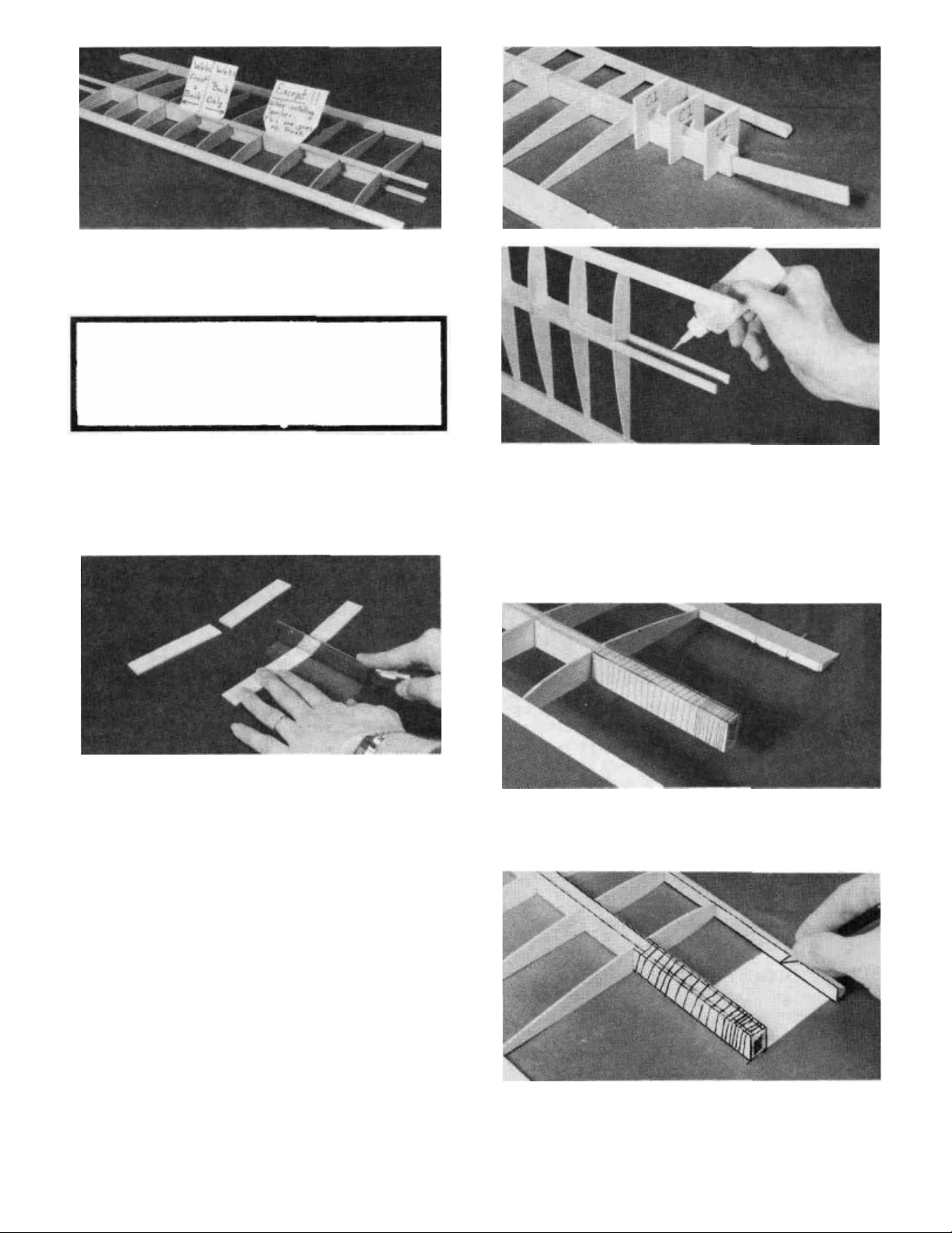
DD 6. Place one of the 1/8" x 5/16" x 23-1/2" Basswood
Inner Spars (SPRTW13) on the wi ng plan and pin the spar
down with crossed T-pins as shown in the following sketch.
NOTE: The spars ma y be cu t slightly oversize, the excess
will be cu t off later.
T-Pins
Work Surface
Spar
D 2. The Shaped Wing Leading Edges (SPRTW10) are
fastened together by thin strips of balsa. Separate them by
carefully cutting between the LE'S. Sand away the excess
balsa that remains along the edges after cutting them apart,
using a sanding block with 100-grit sandpaper.
D 3. Before using the 1/8" x 5/16" x 23-1/2" Basswood
Spars (SPRTW13), examine them carefully for possible
imperfections. Look for knots, soft spots, diagonal grain and
any other imperfections. If possible, position each spar so the
imperfections are on the outer half of the wing panel (toward
the tip), where they will b e least affected by high stress. If the
spars are warped slightly, "balance them out" by installing
the warped spars in opposite directions (see sketch).
TWO WARPED SPARS INSTALLED
THIS WAY WILL RESULT IN A
STRAIGHT WING
TWO WARPED SPARS INSTALLED
THIS WAY WILL RESULT IN A
WARPED WING
DD 7. Place the seven W-2 ribs (from SPRTW02 and
SPRTW03) and the two W-2S ribs (from SPRTW02) on the
spar in their approximate positions, work the ribs into the
notches on the trailing edge bu t do not glue anything yet.
DD 8. Punch out the two Rib Gauge Pieces from the
1/8" die-cut plywood sheet (SPRTW08) and assemble them
using CA. Notice that one end of the gauge is slanted at a 5
degree angle for positioning the end ribs. The other 3 ends are
perpendicular and can be used to keep parts 90 degrees to the
work surface.
9
Page 10
edges are NOT symmetrical. Refer to one of the section
views on the plans to determine which way they should be
installed. Carefully hold the leading edge against one o f t he
end W-2 ribs and note that i t i s wider than the front of th e rib.
This i s because the 1/16" balsa leading edge top sheeting will
be added later. Align the lower surface of the leading edge
with the bottom of the rib and glue it in place with a drop of
thin CA. Lift up the other end of the leading edge, align it with
the bottom of the opposite end W-2 and glue it with a drop of
thin C A . Go down the line and glue the remaining ribs to th e
leading edge one at a time so you can make sure they are
aligned.
DD 9. Make sure the ribs are properly positioned accord-
ing to the plans and glue them in place using thick CA at the
spar joint and a drop of thin CA at the trailing edge joint. Use
the square end of the rib gauge to keep the ribs perpendicular
to the work surface. NOTE: if you are installing spoilers,
cut out the embossed area on the two W2S ribs and make
sure you install these ribs in the proper locations.
DD 10. Trial fit the top 1/8" x 5/16" x 23-1/2" Basswood
Inner Spar (SPRTW13) into the notches in the ribs by
carefully pushing the spar completely down into the notches.
Make sure the lop spar i s lined up lengthwise with the bottom
spar. Remove the spar and glu e it in place by applying thick
CA to the notches before the spar is put back in place.
1/16" sheeting will
be added later
-Bottom of rib should
be flush with bottom
of leading edge.
DD 12. Locate the 1/16" Balsa Die-Cut Shear Web
She et (SPRTW07) and notice th at all of the shear webs are
not t he same. The webs between the number 2's are for use
on the inner panel. The webs between the 2 and the 1 0 are for
the outer panel and each one of these is a different size so keep
them in the sheet until they are ready to be used. Punch out
all of the "2" shear webs.
DD 11. Position a Pre-shaped Leading Edge
(SPRTW10) in place over the plans. NOTE: These leading
DD 13. Trial fit one of the webs in place between the first
two W-2 ribs. You may have to sand it slightly to get it to fit.
Glue the shear web in place on the back of the spars using
thick CA. The webs should be centered (up and down)
between the spars. It is important to do a good job of gluing
these in place as they are responsible for most of the wing's
strength. C-2 Clamps from the 1/8" Die-Cut Plywood Sheet
SPRTW08 can be used to help hold the webs in place while
the glue cures.
DD 14. Install the remaining balsa shear webs. Note that
the webs are only installed between the ribs already glued in
place. Three webs are also installed on the front of the spars
10
Page 11
in the first three rib "bays". NOTE: if you are installing
spoilers in the wing or may add them in the future, install
the web between the two W2S ribs on the FRONT of the
spars to make room for the spoiler horn.
IF YOU ARE BUILDING A ONE-PIECE
WING, SKIP AHEAD TO "BUILD THE
OUTER WING PANEL" ON PAGE 12. STEPS
1 5 THROUGH 22 ARE FOR A 2-PIECE WING
ONLY.
DD 15. Locate the 1/8" die-cut sheet (SPRTW04) that
contains the Dihedral Braces, the Leading Edge Brace and
the Wing Joiner Lamination. Line a ruler up with the two
embossed cut marks and draw a line across both of the
dihedral braces.
DD 16. Punch out the two dihedral braces and cut them in
half with a razor saw along the lines you jus t drew. Note:
these braces are supplied in one piece for the bolt on wing
option. Also punch out the wing joiner lamination from that
sheet and set it aside for the next step. The leading e d ge brace
is not used in a two-piece wing.
DD 17. Punch out the three C1 clamps from the 1/8" diecut plywood sheet (SPRTW08). Test f i t two of the dihedral
brace "halves" to the "root" (inner) end of the inner panel
spars. One brace should be installed on the front of the spars
and the other on the back. The edge that you cut with the razor
saw should be near the end of the spars and it should be placed
s o that i t slants in at the top (towards the middle o f the wing).
Use the C1 clamps to hold the braces in place and test fit the
wing joiner lamination into the box formed. This "box" will
be referred to as the "joiner box". The wing joiner lamination is used to make sure the spars remain the correct distance
apart. (See photo at the top of the next column.)
DD 18. Remove the clamps and apply a bead of epoxy
along the spar edges (thick CA will also work b ut be very
careful to get things aligned properly before the glue cures).
Install the braces and hold in place wi th the C1 clamps. A
goo d glue joint is important here but be careful not to get any
excess glue inside the box formed by these braces or the wing
joiner will not fit ins ide. Also test the size of the joiner box
with the joiner lamination while th e glue is curing.
DD 19. Tightly wrap the joiner box with a strong thin
thread and then soak it with thin C/A. This will add a lot of
strength to the joiner box. Do not overlap the thread or allow
it to build up too thick.
DD 20. Locate one of the 1/16" x 3" x 30" Balsa Sheets
(SPRTW 17) and cut it into 6 pieces 2-3/8" long. Slide one of
the sheets in place in front o f the joiner box and trim to fit. Use
11
another sheet to shim up the frontedge (See sketch nextpage).
Glue it in place with thick CA.
Page 12
1/16"
balsa
scrap
Shaped
balsa LE
1/16" balsa
bottom sheet
Spars
Work Surface
DD 20 . Glue another piece to the rear of the joiner box and
then cut a third piece to fit behind the second and glue it in
place.
DD 1. Lay one of the Outer Trailing Edges
(SPRTW 1 2) in place over the plan and cut it to length just past
the last notch. Align th e notches in the trailing edge with th e
notches on the plans and pin it in position. NOTE: The un-
notched end of this trailing edge will be used later if you
are installing spoilers.
DD 2. "Cross pin" one of the 1/8" x 5/16" x 15-1/8"
Basswood Outer Spars (SPRTW 14) in place.
DD 2 I.Punch out three W1A ribs and three W1B ribs from
the l/8"die-cut balsa rib sheet(SPRTW01). Tes t
fit
these ribs
into position. A little sanding may be necessary to make them
fit properly. Glue these ribs into place using thick CA. The
end rib should be tilted in at the top using the slanted end of
the rib gauge to give it the correct angle.
DD 22. Cut and sand the leading edges, trailing edges and
spars to their correct length. Lay the panel over the plans to
determine the correct lengths.
BUILD THE OUTER WING PANEL
You'll need the following parts:
SPRTW03 1/16" Die-Cut Balsa Wing Ribs W4 - W10
SPRTW07 1/16" Die-Cut Balsa Shear Webs
SPRTW10 Shaped Balsa Leading Edge
SPRTW 12 Shaped, Notched Balsa Outer Trailing Edge
SPRTW14 1/8" x 5/16" x 15-1/8" Basswood Outer Spars
SPRTW15 7/8" Shaped Balsa Wing Tip Block 12
DD 3. Punch out the 1/16" (W4-W10) Tip Ribs ou t of
one of the SPRTW03 die-cut sheets. Glue the ribs in place
with a thick C A at the spar joint and a drop of thin CA at the
trailing edge joint. Use the rib gauge to keep the ribs
perpendicular.
DD 4. Trial fit the top 1/8" x 5/16" x 15-1/8" Basswood
Outer Spar in place by carefully pressing the spar int o the
notches until it is flush with the top of the ribs. Remove the
spar and apply thick C A to the notches. Replace the spar and
allow the glue to cure.
DD 5. Lay one of the remaining Pre-Shaped Leading
Edges over the LEADING EDGE TEMPLATE at the top
rig h t comer of the plans. Use this drawing as a reference to
cut the leading edge to length and to cut the relief notches. It
is a good idea to cut the leading edge approximately 1/4"
longer on both ends to be on the safe side. It can be cut to
the correct length after it is installed. The relief notches do
not need to go all the way through the leading edge but should
go within 1/8" of doing so. NOTE: You must make a
"Right" and a "Left" L.E.
Page 13

DD 6. Carefully bend the leading edge to the angle
shown on the plans and position it against the ribs. The bends
should be at ribs W6 and W9. Align the leading edge with the
top and bottom edges of the ribs and glue it in place starting
at ribs W6 and W9.
DD 7. Locate the remaining 1/16" Die-Cut Shear Webs
from sheet (SPRTW07). NOTE: These remaining shear
webs are actually tapered to match the taper of the wing.
DD 8. Punch out the remaining 6 shear webs and lay
them end to end so that the end of one web is the same siz e as
the end of the one next to it as shown in the sketch below. This
is the order and direction they will be installed in the wing.
The thinnest web goes between ribs W9 & W10 and the
thickest web goes between ribs W4 & W5.
NOTE TAPER OF WEBS
W9-WIO W8-W9 W7-W8 W6-W7 W5-W6 W4-W5
DD 11. Glue the 7/8" x 1-1/4" x 6-1/4" Tapered Wing
Tip Blocks (SPRTW15) to W10 with thick CA. The sketch
below and the cross sections on the plan shows how the block
should be attached to get the correct tip shape.
DD 9. Glue the webs into their respective places using
thick CA. The thinnest end of each web goes towards the tip
of the panel. The C-2 clamps can be used to help hold the
webs in place while the glue cures.
DD 10. Cut and sand the trailing edge, spars and leading
edge flush with rib W 10. Also cut these to the correct length 1 3
at the other end using the plans as a guide.
DD 12. Carve and sand the wing tip to blend in with rib
W10. Be careful not to change the shape of W10 while
sanding the tip. There are three section views on the left wing
plan to show you the desired shape.
Page 14

DD 13. Apply several drops of thin CA to the rear portion
of the balsa wing tip. Allow the glue t o soak into the wood and
cure. The glue will help harden the wood and protect it from
damage.
JOIN THE INNER AND OUTER WING
PANELS
sand the leading edge, spars and trailing edge so they are all
even and of the correct length.
NOTE: The SPIRIT'S wing is designed to be
just under the legal maximum projected wing
span for 2-meter sailplanes (approximately
78-3/4"). Be very careful when joining these
panels to get t he right amount of dihedral and
to keep the panels the correct length or you
could very easily build a wing that is too long
for competition in the 2-meter class.
DD 1. Prop up the outer panel 2-5/8" (from the work
surface to the bottom of W10) using the lower notch of the
Dihedral Gauge (from SPRTW08) next to rib W9. Use a
sanding block to carefully sand the leading edge, spars and
trailing edge to achieve vertical surfaces on each. Check your
progress by occasionally setting the panel on the plans to
make sure you are not sanding any "sweep" (forward or
backward tilt) into the wing.
DD 2. With the inner panel flat on the work surface,
DD 3. Test fit the inner and outer panels together over
the plan to make sure the leading edges, spars, and trailing
edges all meet up nicely when t he tip panel is blocked up the
required 2-5/8" at the bottom of rib W 10 (Use the lower notch
of the dihedral guage at W9 as shown on the plans to obtain
the correct angle). Sand a ny ends if needed to make everything fit well.
DD 4. With the dihedral gauge in place. Apply thick CA
or epoxy to the leading edge, trailing edge and spar joints to
"tack glue" the two panels together. Hold everything in
place until th e glue has cured.
DD 5. Punch out two of the 1/32" Plywood Polyhedral
Braces from the die-cut sheet (SPRTW06) and test fit them
in place against the front and back of the spars. Sand them if
needed to achieve a good fit .
DD 6. When satisfied with the fit apply a generous bead
of epoxy or thick CA to the spars and install the braces on both
sides of the spars. Use the die-cut C2 clamps (from
SPRTW08) to hold everything in place. The photo at the top
of the next page shows this procedure.
14
Page 15

DD 7. Glue the 1/32" Plywood Polyhedral LE Brace
(from SPRTW06) in place against the leading edges. Install
ribs W3A and W3B between the inner and outer panels using
thick C A as shown in the photo. A little sanding may be necessary to achieve a good fit. Use the rib gauge to tilt the ribs
to the proper angle.
D 2. Use either epoxy or thick CA to glue one of the 1/16"
laminations to the 1/8" laminations. Apply as much pressure
(clamps, clothespins, weights, etc.) as possible while the glue
is curing and be sure to accurately line up the two pieces.
Next, glue this lamination assemby and the other 1/16" lamination, one on each side, to the aluminum joiner using epoxy
(The alumium joiner and the 1/8" Lamination should be i n th e
middle). Clamp together until the glue cures.
D 8. Now go back to step 5 on page 9 and assemble the
other half of the wing.
FINAL WING ASSEMBLY
IF YOU ARE BUILDING A ONE-PIECE
WING SKIP AHEAD TO STEP 4
D 1. Punch out three of the 1/16" an d one of the 1/8" Plywood Wing Joiner Laminations (SPRTW05 / SPRTW04)
and find the aluminum joiner. Lightly sand the edges of each
to remove any high spots.
D 3. Sand the edges of the finished "wing joiner" to
remove any glue globs and test fit it in the wi ng joiner box.
Some sanding may be required to get a nice smooth but not
loose fit.
IF YOU ARE BUILDING THE TWO.
PIECE WING SKIP AHEAD TO STEP 15
D 4. Prop up one wing half 2" (as measured from the work
surface to the bottom of rib W3) and sand the root (Inner) en d
of the trailing edge, spars and leading edges to achieve
vertical surfaces as you did earlier for the outer panels. Do the
same for the other wing panel.
D 5. Test fit the two inner panels together by laying one
panel flat on the work surface and propping up the other
panel 4" (at the bottom of ri b W3). Use the dihedral gauge
next to the last W2 rib to achieve the correct angle. Make sure
that each spar, etc. j u s t touches the opposite spar, etc. of the
other panel. Carefully sand the longest ends until a good joint
15 is achieved between each member.
Page 16

D 6. Punch out all four of t he Wing Joiner Laminations,
the Dihedral Braces and the Leading Edge Brace from the
die-cut sheets SPRTW04 an d SPRTW05. Test f it all of the
pieces in place and sand them if necessary to make them fit
nicely. The wing joiner laminations a re installed between the
spars and arc sandwiched in place by the dihedral braces. The
C1 clamps can be used to hold ev e rything in place.
place using thick CA. It should be centered (up and down) on
the leading edge because 1/16" sheeting w i ll be added later.
D 9. Locate one of the 1/16" x 3" x 24" Balsa Sheets
(SPRTW17) and cut it into 6 pieces 2-3/8" long. Slide one of
the sheets in place in front o f the dihedral brace, trim it to fit
and glue it to the LE and the dihedral brace with thick CA.
D 10. Glue another piece to the rear of the dihedral brace.
then cut a third piece to fit behind the second and glue it in
place.
D 7. When satisfied with the fit, mix up a batch of epoxy
(30 minute cure time is ideal, 5-minute is too fast), coat the
joiner laminations with a layer of epoxy and install the joiner
laminations between the spars. Quickly apply some epoxy to
the dihedral braces and hold them in place using the C1
clamps. Also apply some glue to the leading and trailing
edges and pin them together to keep them aligned with one
another. Wipe off any excess epoxy that may have squeezed
out before it cures. After the glue cures sand off any glue
globs that may have formed.
D 8. Glue the 1/8" Plywood Leading Edge Brace in
IF YOU ARE BUILDING A ONE-PIECE
WING THAT WILL BE ATTACHED
WITH RUBBER BANDS, DISREGARD
STEPS # 11,12,13 and 14 and instead just
glue all six W1A and W 1 B ribs in place.
D 11. Punch out six W1A ribs and six W1B ribs from the
1/8" d i e-cut balsa rib sheet (SPRTW01). Test fit these ribs
into position. A little sanding may be necessary to make them
fit properly. Glue all six W1B ribs into place using thi ck CA
(the two center W1B ribs arc glued together). Glue the outer
two W1A ribs into place but the remaining four W 1 A ribs will
not be added until later.
D 12. Cut a piece of 1/4" birch plywood (not included) to
fit between the leading edge and the spars. It will be called the
Front Wing Bolt Plate and should b e approximately 2-1/8"
x 2-5/16". Glue the wing bolt plate in place with either epoxy
or thick CA. Add strips of 3/16 triangle stock wherever
possible along the joints to help reinforce it.
D 13. Glue a W1A rib to each side of the wing bolt plate.
Trim the other two W1A ribs to fit together on top of the wing
bolt plate and glue them in place. Cut out a section of these
two W 1 A ribs to clear the wing bolt as shown in the sketch on
the top of the next page.
16
Page 17

-Cut W1A Rib and Leading Edge Sheeting
away to clear Nylon Wing Bolt
D 14. Add a 5/16" x 1" x 7/8" balsa filler block (not
included) on each side of the middle W1B ribs near the
trailing edge and sand them flush with the top of the ribs.
and act as a lunge for the gluing process. Press the sheeting
into place and trim it flush with the back edge of the spar using
a modeling knife and straightedge.
STEPS 15 - 18 APPLY TO ALL WING
CONFIGURATIONS
D 15. Set the 1/16" x 3" x 24" Balsa Leading Edge
Sheeting (SPRTW17)in place on the inner panel. The outer
end of the sheeting should cover rib W3A. Cut off the excess
sheeting even with rib W1A. Sand the top L.E. of the ribs if
necessary to allow the sheeting to be flush with the L.E.
D 16. With the 1/16" sheeting in place against the leading
edge apply several strips of masking tape to hold it in place
D 17. Lift the sheeting up and apply a bead of thick CA
along the top spar. Quickly press the sheeting down into place
and hold until the glue h as cured. A straight strip of wood the
length of the panel can be a big help when trying to hold the
sheeting down evenly.
D 18 . Apply a small bead of thin CA between the pieces of
masking tape along the leading edge. When al l of the glue has
cured, remove the tape, flip the wing over and securely glue
the sheeting to the ribs using thin CA as shown in the photo
at the top of the next page. Poke some pin holes in the center
sheeting where the center W1A rib is and apply a drop of thin
CA to each hole.
17
Page 18

IF YOU ARE NOT INSTALLING
SPOILERS SKIP TO STEP 28
D 19. Cut one 6-1/4" long spoiler from the UNNOTCHED scrap end of each Outer Panel Trailing Edge
(SPRTW12). Also cut two pieces of 3/16" x 1/4" balsa
6-9/32" long, four pieces 1-1/4" long, two pieces 1" long and
two pieces of 1/16" x 1/8" balsa 6-9/32" long. This wood is
not supplied in the kit bu t can be purchased at your local
hobby dealer. Set half of the pieces aside for the other side of
the wing.
D 23. With the spoiler in place, glue the 3/16" x 1/4" x
1-1/4" pieces of balsa to ribs W2. These are the spoiler rests
and should be positioned so they hold the spoiler flush with
the top surface of the wing. NOTE: It is important that th e
spoiler sit flush with the top of the wing o r it will unnecessarily disrupt the airflow over the wing.
D 24. Drill 1/8" holes in the ribs as indicated on the plans an d
snake a 1/8" diameter nylon tubing (Inner pushrod tube or
antenna tube, not included) through th e ribs. Cut a 1/ 8 " wide,
1/8" deep notch in the middle of the 3/16" x 1/4" x 1" piece of
balsa and glu e i t to t h e bottom of the 3/16" x 1/4" x 6-9/32"
piece trapping the end of the spoiler tube in the notch as
shown in the photo.
D 20. Glue the 1/16" x 1/8" x 6-9/32" piece of balsa to th e
back edge of the sheeting between the W2 ribs as shown on
the plans and in the photo.
D 21. Glue the 3/16" x 1/4" x 6-9/32" piece of balsa in its
notch on the W2S ribs. It should also be glued t o the W2 ribs
at the ends and it should be flush wi t h the TOP of the ribs.
D 22. Test fit the spoiler in its bay and sand it if necessary
to achieve a 1/32" gap around the sides and trailing edge. Use
a strip of masking tape to temporarily hinge the spoiler in
place.
D 25 . If you are using the spoiler setup shown o n th e plans,
the spoiler tube should exit the bottom of the wing just behind
the wing joiner box and the nylon tube should protrude
approximately 4 " to help the spoiler string clear the servos in
the fuselage. Drill a 1/8" hole in th e bottom center section
sheeting for the tube, insert the tube in place and glue the lube
to every rib and the sheeting using thick CA.
18
Page 19

these sheets to match the contour of the wi ng and be careful
not to add much to the wingspan with these extra sheets.
D 30. Sand three edges (two short and one long edge) of
each 1/16" Plywood Wing Protector (SPRTW18) to a taper
as shown on the plans and glue them in place on top of each
trailing edge. They should be oriented so the unsandcd edge
is flush with the back of the trailing edge an d they should be
placed 9/16" a way from the root of th e wing. These wi ll
protect the wing trailing edge from being dented.
Wing Protectors
FUSELAGE ASSEMBLY
D 26. Drill a 1/16" hole in each 1/16" Die-Cut Plywood
Spoiler Horn (SPRTW05) at the indentation. Cut a 1/16"
wide slot in the spoiler for the spoiler horn using a razor saw
(a hack saw blade wil l also work fine) and glue the horn in
place. It should be flush with the top surface of the spoiler as
shown on the plans. This completes the assembly of the
spoilers until after the wing is covered.
D 27. Assemble the spoiler on the other wing panel.
STEPS 28 AND 29 APPLY TO ALL WING
CONFIGURATIONS.
You'll need the following items:
SPRTF01 3/32" Balsa Fuselage Sides, Wing Saddle Tripler
SPRTF02 3/32" Balsa Fuselage Doublers
SPRTF03 1/8" Plywood From Fuselage Bottom
SPRTF04 1/16" Balsa Rear Fuselage Sheeting
SPRTF05
SPRTF07 1/8" Square x 24" Balsa Stringer
SPRTF08 3/16" x 30" Balsa Triangle
SPRTW05 1/16" Plywood Towhook Plate
1/8" Plywood Formers
ASSEMBLE FUSELAGE SIDES
D 1. Pin or tape the fuselage plan to your flat work
surface and cover it with waxed paper. Pin one of the 3/32"
Die-Cut Balsa Fuselage Sides (SPRTF01) down ABOVE
the FUSELAGE SIDE VIEW so y ou can use the plan for
reference. This is going to be the LEFT fuselage side.
D 28. Use the remaining piece of 1/16" balsa sheeting to
sheet the top inboard center section out past rib W1B as
shown in the photo. Thick CA should be used for this step.
Pre-cut the sheeting t o fit first near the spars, and cut a second
piece to fit between the first piece and the trailing edge. Glue
these in place and if you built a two-piece wing, sand the
sheeting flush with the W1A and W1B ribs at the wing root.
D 29. If you built a two-piece wing, trial fit the two wing
halves together using th e plywood wing joiner. Sand the root
of each panel if necessary to achieve a nice close joint
between the two wings. If there are large gaps, glue a sheet
of 1/16" balsa to the root of the panels to fill the gaps. Sand
DD 2. Trial fit one of the 3/32" Die-Cut Balsa Front
Fuselage Doublers (SPRTF02) onto th e 3/32" Balsa Fuselage Side. The doubler should line up with the fuselage where
the canopy wi ll sit. The arrows i n t he photo point out this
area. Spread a thin layer of thick CA on the doubler and glue
it to the fuselage side.
19
Page 20

DD 3. Glue the 3/32" Die-Cut Balsa Rear Fuselage
Doubler (SPRTF02) in place making sure it lines up with the
fuselage sides at the rear of the doubler where the arrows in
the photo arc pointing.
DD 4. Glue one of the 3/32" Die-Cut Balsa Wing
Saddle Triplers (SPRTF01) in place on lop of the front
fuselage doubler. Do not let the tripler overlap the notches for
the formers.
FRAME-UP THE FUSELAGE
D 1. Lay a piece of waxed paper over t he FUSELAGE
TOP
VIEW. Assemble but do not glue
Plywood Front Fuselage Bottom (SPRTF03) and the 3 / 3 2 "
Die-Cut Balsa Rear Fuselage Bottom (SPRTF04) together
over the FUSELAGE TOP VIEW on the plans. The 1/8"
plywood bottom should be installed with the three towhook
hole marks DOWN so you can tell where to drill the towhook
holes after the fuselage is assembled. Make su re th e bottoms
are aligned with the plan and that both pieces are pushed
firmly against the work surface to even up the bottoms. If the
joint is a nice tight fit, apply thin CA to the joint. If the joint
is a little loose, tak e the bottoms apart, apply thick CA and
reassemble them.
glue
yet
1/8"
Die-Cut
DD 5. Cut one of the 1/8" Square Balsa Stringers
(SPRTF07) to fi t between the notch for former F5 and the rear
doubler and glu e it in place making sure it is lined up flush
with the lop edge of the fuselage side (excluding the tabs).
Cut another 1/8" sq. balsa stringer to fit along the bottom
between the rear doubler and the notch for former F5 and glue
it i n place. Make sure it is lined up flush with the bottom edge
of the fuselage side (excluding the tabs).
D 6. Go back to step 2 and assemble the RIGHT fuselage
side. The easiest way to do this is to pin the other fuselage side
upside down above the one you just built as shown in the
photo. MAKE SURE YOU ARE NOT BUILDING TWO
IDENTICAL SIDES, THEY SHOULD BE THE OPPOSITE OF EACH OTHER.
D 2. Trial fit all of the 1/8" Plywood Formers (except
Fl) in the respective notches in the fuselage bottom and sand
them if needed to make them fit properly. Use thick CA to
"Tack" glue the formers in place. The notches in the
fuselage sides will align the formers correctly.
D 3. Align the fuselage sides with the fuselage bottom
and position the formers so they will key into the notches.
Remove the assembly from the work surface and use rubber
bands to hold it all together.
D 4. Check the fit of the 1/16" Plywood Tow-hook Plate
(SPRTW05) in its slot between formers F4 and F5. Enlarge
the slot if needed to make the plate fi t and glue it to the
20
Page 21

fuselage bottom with thick CA. Use the fuselage sides to help
position it.
joints and around former F 6 . Take your time apply ing the thin
CA and be sure to get the bottom and the sides pressed
together nicely. Thick CA can then be added to these joints
to add strength.
D 7. Pull the front fuselage sides together and trial fit the
1/8" Plywood Former F1 in place. Apply t hick CA to the
front fuselage bottom and the formers, install F1 and pull the
fuselage sides together. A few rubber bands can be used to
help hold the assembly while the glue cures.
D 5. Spread the fuselage sides ou t and apply thick CA to
formers F4 and F5 and the fuselage bottom between them.
Reassemble, check to make sure the sides are pressed firmly
against the formers and the bottom is ful l y seated against the
sides, and allow the glue to cure.
D 6. Pull the rear fuselage sides together and make sure
that the sides are pressed firmly against former F 6 and that the
bottom is fully seated against the fuse sides. A couple of C2
clamps can be used to hold the tail of the fuselage together and
rubber bands will help around the formers. Apply a couple of
drops of thick CA on the back edge of the rear fuselage
doubler and a bead of thin CA along the bottom sheeting
D 8. Trial fit the 3/32" Balsa Rear Top Fuselage Sheet
(SPRTF04) in place*, and when satisfied wit h its fit apply a
bead of thick CA along the 1/8" balsa stringers, the fuselage
doublers and the fuselage sides and glue it in place. *NOTE:
The top sheeting should be installed s o the rudder pushrod
cut-out is on the le ft side of the fuse. Check the plans for
the proper orientation.
D 9. Cut the 3/16" Balsa Triangle (SPRTF08) into th e
following lengths:
two pieces - 4-5/8" long
four pieces - 2" long
two pieces - 4-1/16" long
two pieces - 2-7/8" long
one piece - 1-1/4" long
21
Page 22

These pieces should be glued wi th thick CA. They are
pressed into t he corner between t h e fuselage bottom and the
fuselage doubler in th e following places:
Glue the 4-5/8" pieces behind the towhook plate.
Glue the 2" long pieces on top of and in front of the
towhook plate.
Glue the 4-1/16" long pieces between formers F3 and F4.
Glue the 2-7/8" long pieces between former F2 and F3.
And glue the 1-1/4" long piece along the bottom between
formers F1 and F2 to seal the gap there.
inside
of
the
fuselage)
CA around the outside edge of each blind nut (be careful not
to get glue inside the blind nut!).
with a hammer and put a drop
of
thick
IF YOU ARE NOT BUILDING A
BOLT-ON WING SKIP AHEAD TO
"ASSEMBLE THE CANOPY".
D 10. Sand the fuselage sides and bottom flush with the
front of former F1 and glue the Shaped Balsa Nose block
(SPRTF10) in place with thick CA. The bottom of the nose
block should overlap the fuselage bottom by about 1/32" to
allow for sanding to final shape.
D 11. Drill three 9/64" (1/8" is light but will work) holes in
the 1/8" plywood bottom for the towhook. There should be
three indentations to show you where to drill. Gently Tap the
three 4-40 Blind Nuts (NUTS001) into the holes (from the
D 12. Cut two pieces of 1/4" birch plywood (not included)
which will be drilled and tapped for the wing bolts. The front
piece should be approximately 2-1 /32" x 1" and the rear piece
should be approximately 2" x I". You will want t o measure
your fuselage to make the parts fit properly. You should cut
the wing saddle tripler away s o the blocks can glue directly to
the fuselage doubler. Securely glue these in place with thick
CA or epoxy. Glue triangle stock around each one for extra
strength.
D 13. Glue a 1/16" Plywood Rear Wing Bolt Plate (not
included) on top of the wing trailing edge to protect it from
being crushed by the rear wing bolt (see the wi ng plan top
view for the approximate size and shape).
22
Page 23

D 14. Insert the 1/4" wing dowels in the holes in the
fuselage and temporarily rubber band the wing in position on
the fuselage and use a string as shown in the sketch to make
sure it is on straight. Make a couple of marks on t he wing a n d
fuse to help you make sure it stays in position while drilling
the wing bolt holes.
D 1. Trial fit the 1/8" Plywood Canopy Back
(SPRTF05) and the 1/8" Plywood Canopy Front
(SPRTF05) in place in the Formed ABS Cockpit
(SPRTF12). Sand them if necessary for a good fi t and then
glue them in place with thick CA.
D 15. Drill a 13/64" hole through the wing and 1/4" ply
plate in the fuse approximately 1" behind the front of the
leading edge.
in front of the rear of the trailing edge as shown on the
FUSELAGE SIDE VIEW of the plans.
D 16. Remove the wi ng and enlarge the two holes in the
wing to 17/64". Use a 1/4 - 20 tap to thread the holes in the
fuselage blocks. Test fit the wing i n place with 1/4 - 20 nylon
bolls (not included). Cut the 1/16" top sheeting away to clear
the front wing bolt.
Drill
another 13/64" hole
approximately
1-1/4"
ASSEMBLE THE CANOPY
You'll need the following items:
SPRTF06 1/8" Balsa Canopy Base
SPRTF05 1/8" Plywood Canopy Front and Back
CANPY044 Clear Canopy
SPRTF12 Formed ABS Cockpit
D 2. Sand the bottom edges of the canopy front and back
flush with th e bottom of the cockpit. Be careful not to sand
through the cockpit. A small flat file works well for the front
former.
D 3. Check the fit of the 1/8" Balsa Canopy Base
(SPRTF06) in the cockpit. Sand the sides of the base until it
will easily fit into the cockpit. When satisfied with the fit glue
it in place w i th thick CA.
D 4. Cut and sand off the extra cockpit material flush
with the edges of the canopy back, canopy base, and canopy
front. Saturate the front edge of the canopy base with thin CA
and allow it to soak in and cure. This is where the canopy hold
down dowel wil l rest. Sand the front and back edges of the
base flush with the Canopy Front and the Canopy Back.
D 5. Paint the cockpit with the color scheme of your
choice. Test the paint you are going to use on a piece of the
plastic you cut off to make sure it will not affect the plastic.
Regular plastic model paints usually work well for this. Do
not paint the edges of the cockpit where the canopy will attach
or the glue will no t hol d a s well. Striping tape can be used to
cover that seam. Lightly sand the edges to help the canopy
23 adhere.
Page 24

D 6. The canopy may have a Plastic Film on either or both
sides. Check for t his and remove it if you find one. Tint the
Canopy (CANPY044) if you wish, using powdered clothing
dye that you can buy at the grocery store (Rit, etc). Use very
warm water (warmer than you can leave your hand in) but do
not use very hot water or the canopy may deform. The
warmer the water and the longer you leave the canopy in the
dye, the darker the tint will be. Liquid dyes do not seem to
work as well.
D 7. Set the cockpit inside the canopy and line the cockpit
up with the scribe lines in the canopy. The scribe lines are
only for reference while positioning the cockpit, do not try to
get the cockpit to fit the scribe lines. Glue the canopy to the
cockpit using CA. Use the glue very sparingly by holding th e
cockpit in place inside the canopy and apply glue a drop at a
time to the seam. The glue will seep in along the seam and
provide a nice clean glue joint. Work you r w a y around the
canopy and don't get in a hurry or you may get too much glue
in there and it wi l l r u n d o wn th e ca nopy. Be careful not to
twist or move the cockpit once y o u start gluing it in place.
D 10. Measure up along the nose block 1/4" from the
fuselage side and make a mark. Do this on both sides of the
nose block and then draw a line across between the two
marks. Measure to the middle o f thi s line and make another
mark. Drill a 1/8" diameter hole about 1" deep at approximately the angle shown on the plans right where you made the
last mark.
D 8. Trim the canopy flush with t h e base and the front but
do not trim the back yet! A small pair of scissors works well
for trimming the canopy. Temporarily mount the wing in
place on the fuselage. VERY CAREFULLY trim the back
of the canopy, A LITTLE AT A TIME, to fit over the wing.
Take your time and use the outlines on the plans and the wing
for guides.
D 9. Test fit the canopy onto the fuselage. You can sand
the edges of the canopy slightly or you can sand the fuselage/
nose block if needed to get it to fit properly. You can also add
a layer of balsa to the back edge of the nose block to take up
any extra gap if needed.
D 11. Insert the 1/8" diameter Canopy Hold Down
Dowel (DOWEL033) into the hole and slide the canopy into
place to make sure it fits nicely. The dowel should hold the
canopy down against the fuselage. If it is too loose you can
either enlarge the hole slightly and move th e dowel down or
you can build up th e top surface of the canopy base with thin
plywood and/or thick CA. Glue the dowel in place wit h at
least 1/4" extending.
D 12 . Cut two pieces of 1 / 8 x 3/1 6" balsa (from SPRTS03),
one 1-7/8" long and the other 1-1/4" long. Wedge the longer
piece between the fuselage sides above the receiver compart-
24
Page 25

merit and wedge the other one between the sides in the weight
compartment. These pieces arc called the Canopy Aligners.
Lift the aligners so that they are slightly above the sides.
Apply a small drop of thick CA to the middle of each aligner
and carefully slide the canopy into place. Push down on the
canopy to force the aligners against the canopy base (with t he
canopy aligned with the fuselage sides) and hold it until the
glue has cured (a couple of minutes). Carefully remove the
canopy and securely glue the aligners to the canopy base with
more CA.
D 13. Apply a couple strips of masking tape around the
front of the canopy to protect the plastic and install the canopy
on the fuselage. Use a razor plane, hobby knife or sanding
block with coarse grit sandpaper to rough carve the nose
block to shape.
plane fore and aft". That very important step
will be covered later in the manual.
Now that you have the basic airframe nearly completed,
this is a good time to balance the airplane laterally (side-to-
side). Since the wing is the major factor on a sailplane, we
will only be concerned with it. Here is how to do it:
1. Set t he wing o n a flat surface and hold i t s o that both
wing tips are level. Let go of the wing and notice which wing
tip drops. Do this several times and if the same wing tip keeps
dropping push a thumb tack or small nail through rib W 1 0 into
the wing tip that keeps rising.
2. Perform this test several times until the wing balances or the same wing ti p does not drop every time and then
glue the tacks or nails in place with a drop of thin CA.
FINAL SANDING
Check over the entire structure carefully, inspecting for
any poorly glued joints, gaps and "dings". Apply additional
glue and/or balsa filler as necessary, then sand the entire
structure smooth using progressively finer grades of sandpaper. Sand the fuselage corners to a rounded shape as shown
on the cross sections of the plans.
COVERING
D 14. Use your sanding block with medium and then fine
grit sandpaper to smooth out the nose block and fair it in with
the canopy and the fuselage.
FINAL ASSEMBLY
BALANCE THE AIRPLANE LATERALLY
There are many different types of covering materials
available these days but the iron-on type coverings are by far
the easiest to use and in most cases the best suited for the job.
There are also several different brands of iron-on coverings
available. We recommend you use Top Flite Super
Monokote for covering your SPIRIT due to thi s covering's
higher strength. Sailplanes, which usually have higher
"aspect ratio" wings (long and thin), gain a great deal of
strength from the covering. This is evident b y gently twisting
the wing before and after it is covered, it is hard to believe the
difference. Because of this, the higher strength coverings are
best suited for sailplanes.
The following are some covering tips we have learned
over the years but you should follow the instructions in-
cluded with your covering material.
• Sand the surfaces as smooth as possible before starting to
cover the plane. The finished covering job wil l only be as
smooth as the surface you started with.
• Use a fresh single-edge razor blade or hobby knife blade
and replace the blade as soon as it starts showing signs of
dulling.
SPECIAL NOTE: Do not confuse this procedure
with "checking the C.G." or "balancing the air-
• Set the iron to the proper temperature by first applying a
25 "test strip" on a scrap of balsa.
Page 26

• Work outward, start by tacking the covering in place at the
comers and then start in the middle and work your way out to
the comers, gently pulling any wrinkles out as you go.
• Securely seal al l edges! Make sure the edges are firmly
sealed down to prevent the covering from pulling away at the
seams when shrinking the panel.
wing
17. Top of left
and TE)
18. Top of right wing panels (overlap covering 1/4" a t
LE and TE)
19. Spoilers if installed
panels (overlap covering
l/4"at
LE
NOTE: When covering the fin, begin by applying
a 1/2" wide strip of covering on each triangle. Next,
cover the rest of the fin with pre-cut pieces that have
a straight edge to overlap (1/8"+ overlap) the strips
you previously applied. This is a tip you should
remember as it makes it a lot easier to cover
"compound" curves.
Because the fin has to glue on top of the stab and the stab
has to glue to the fuse you do not want to cover where these
surfaces will glue to each other. The following instruction
will explain how to do this.
D 1. Position the stabilizer on the fuselage and aligned
with the fuselage using the procedure at step 3 on page 27.
Hold it in place and mark along the fuselage/stabilizer joint
with a felt pen to show where not to cover.
D 2. Position the fin in place on top to the stab. Make sure
it is centered and pointing straight ahead, and mark around the
base with a felt tip pen.
D 3. When applying the covering to the top and bottom
surfaces of the stab, do each side with two pieces of covering.
Do not cover between the lines. Cut the covering to fit around
the lines before you iron it in place. Also do not cover each
surface of the slab with one sheet of covering and then cut the
covering away between the lines. Doing this leaves "cut
lines" in the wood and greatly weakens the stab structure.
CHECKING FOR WARPS
This is a very important step and should be done every
once in a while throughout the flying season. A sailplanes
wing is most efficient when it is not twisted or warped at all.
"Washout" (wing trailing edge twisted up at the tip) helps
make a poor wing design fly belter by adding some stability
(preventing stalls) at slow speeds but it cuts down on the wing
efficiency at normal speeds. The SPIRIT'S wing is designed
to fly well at slow speeds without a ny washout and therefore
we recommend you check to make sure the wings are "flat"
using the following procedure.
D 1. Set the wing so an inner panel is resting on a flat
surface. Any warp (twist) will show up by cau s ing a comer
of the panel to rise off of the work surface.
D 2. To remove the warp, gently twist the win g in the
opposite direction while a helper glides an iron or heat gu n
over the covering on both the top and the bottom of the panel
to re-shrink the covering. Hold the twist until the covering
cools and then recheck for warps. It may take several trys to
get a warp o ut but it is worth it as you w ill end up with a
sailplane that flies straight and true and responds to air
currents like a high performance sailplane should.
D 3. Follow the same procedure to check all four wing
panels and then go back and double check them. Sometimes
you put a warp in one panel while trying t o fix another. You
should also look at the tail surfaces as they too can warp.
Recommended Covering Sequence:
1. Strips as described in above note
2. Fin left side
3. Fin right side
4. Rudder left side
5. Rudder right side
6. Bottom of elevator
7. Top of elevator
8. Stab bottom right side
9. Stab bottom left side
10. Stab lop right side
11. Stab top left side
12. Fuse bottom
13. Fuse sides
14. Fuse top
15. Bottom of left wing panels (inner and outer)
16. Bottom of right wing panels (inner and outer)
GLUE THE HINGES
D 1. Lay the rudder and elevator on the plans and mark on
the leading edge o f each part the locations of the hinges. Now
use a sharp hobby knife to cut slits in the covering at the hinge
locations. Trial fit the hinges t o make sure you have'' found''
the slots which you previously cut. In the same manner, slit
the covering at the hinge locations in the stab and fin TE.
D 2. When gluing the hinges it is important that plenty of
glue gets inside the hinge slot. If you just put glue on the
hinge, most of it will be wiped off as the hinge is inserted into
the slot. A good way of getting glue into the slot is to scoop
up some epoxy with a plastic soda straw, then pinch the end
of the straw, insert it into the slot, and squeeze the straw to
force the glue into the slot. Apply epoxy to the hinges, insert
26
Page 27

them into place (up to the middle of th e hinge) and wipe away
all excess epoxy with a tissue (for best results dampen the
tissue with rubbing alcohol).
MOUNT THE TAIL SURFACES
D 1. Use your sanding block with medium grit sandpaper
to chamfer (slightly round) the ends of the 1/4" Hardwood
Wing Dowels (DOWEL030) Insert the 1/4" wing dowels in
the holes and secure with thick CA. (Omit this step if you are
using a bolt-on wing.)
place on the rudder and elevator with a drop of thin CA. Use
the plans as a reference for positioning the horns (Rudder on
the left, elevator on the bottom). Drill two 3/32" holes
through the control surfaces using the control horns as guides.
Temporarily mount the horns with the 2-56 x 3/8" Screws
(SCRW001) and the Nylon Nutplates which were attached to
the horns, 2-56 X 3/8" Screw
D 3. Cut 4-1/4" off both threaded ends of the 36" Wire
(WIRES 17) and then cut two pieces 12" long from the
remaining piece of wire. Bend them as shown on the plans
except without the Z-bends. The Z-bends are not bent until
later. Wipe off each wire using a paper towel dampened with
rubbing alcohol to remove any oil.
D 2. Rubber band or bolt the wing onto the fuselage
making sure it is square and centered with respect to the
fuselage.
D 3. Position the stabilizer on the fuselage and measure
to get it centered and properly aligned. Glue the stabilizer to
the fuselage with either thick CA or epoxy. Check its
alignment with the wing while the glue is curing to make sure
they are level with each other.
D 4. Cut the pushrods from the 1/4" Square Balsa Sticks
(SPRTF09). The elevator pushrod should be 17-3/4" long an d
the rudder pushrod should be 15-1/4" long.
D 5. Drill a 5/64" hole 2-1/4" in from both ends of each
pushrod.
D 4. Position the fin in place on top of the stab. Glue the
fin in place on top of the stab and fuse using either thick CA
or epoxy. Check to make sure it is pointing straight at the nose
and is vertical (90 degrees) to the stab.
ASSEMBLE PUSHRODS
D 1. Harden the balsa in the area of the control horns (o n
both sides of the control surfaces) by poking several holes
with a pin, then apply thin CA glue and allow it to so ak in and
cure.
D 2. Tack glue the Nylon Control Horns (NYLON03) in
D 6. Use either a hobby knife, razor plane or coarse
sandpaper to taper three sides on each end of both pushrods.
The taper should start about 1-1/2" from the end. (One of the
sides wit h the 1/16" holes should remain flat).
D 7. Insert one threaded piece of wire into each pushrod.
Insert the 12" pieces of wire into the other end of each
27
Page 28

pushrod. Tack glue the wires in place with a couple drops of
CA. Firmly wrap the end of the pushrod with strong thread
and apply thick CA to hold everything in place as shown on
the plans and in the photo.
two servo horns you cut earlier with the arms facing opposite
directions as shown on th e plans. Operate the transmitter
sticks to make sure the servo horns turn freely without hitting
each other or the fuselage sides. If they do, cut or sand them
until they will operate freely. Turn off the receiver first and
then the transmitter.
INSTALL RADIO GEAR
D 1. Slide one of the 1/4" x 3/8" Basswood Servo Rails
(SPRTF11) into its slot in the fuselage doubler. Slide it all the
way forward and glue it in place wit h thick CA. Slide the
other servo rail into place and then slide it all the way to the
back. Do not glue it yet! Position one of your servos in place
and use it to position the rear servo rail. Do not push the rear
servo rail up tight against the servo but rather leave about a
3/32" gap between the servo "body" and the rear servo rail.
This will give you enough room to put the servos in and out
without removing the rails. Glue the rear servo rail in place.
D 2. Position both of the servos together in the middle of
the rails and mark where the holes for the servo mounting
screws should be drilled. Remove the servos and drill 1/16"
holes where the marks are. Install the servos, with the wires
exiting forward, using the servo mounting screws that came
with the radio.
D 3. Cut three "arms" off of two X-type servo horns
using wire culling pliers or a razor saw as shown in the
following sketch.
D 5. Screw a Nylon Clevis (NYLON17) onto the
threaded portion of each pushrod. Slide the pushrods into t he
fuselage. The rudder pushrod exits the top of the fuselage just
in front and to the left of the fin. The elevator pushrod exits
the hole in th e rear of the fuselage. Snap th e nylon clevises
into the outermost hole in the servo horns. The rudder
pushrod goes to the left servo and the elevator pushrod goes
to the right servo. With the control surfaces in their neutral
position, use a fe lt tip marker to make a small mark on each
pushrod wire where they cross the holes in the control horns.
Remove the pushrods from the fuselage and make a Z-bend in
each wire with the first bend starting where the marks are.
Nylon Clevis
(Airplane shown not covered ,for reference)
D 6. Cut any excess wire off 1/4" past the Z-bend and
reinsert the pushrods into the fuselage. Remove the nylon
control horns from the elevator and rudder and install the
horns onto the pushrods. Both pushrods should connect to the
control horns through the second hole from the inside. Rein-
stall the control horns to the elevator and rudder. Adjust the
nylon clevis or the bends in the wire until the control surfaces
are at neutral when the servo horn is perpendicular to the
centerline of the fuselage.
D 4. Read and follow the instructions that came with your
radio to install o r charge the batteries and get the servos ready
for mounting. Plug the servos and the battery pack into the
receiver and turn on the transmitter first and then the
receiver. Adjust the trim levers to their neutral positions and
allow the servos to return to their neutral positions. Install the
D 7. If you are installing spoilers, mount the spoiler servo
between formers F3 and F4. It can be mounted on servo rails,
or on its side with servo tape. C ut 3 arms off of an X-type
servo horn as you did for the tail surfaces and mount a #2 x
3/8" (not included) screw in the outer hole. Adjust the servo
and your transmitter so the hom is almost pointing towards
the rear of the plane when your transmitter stick is in the
"spoilers closed" position. The horn should rotate towards
the front o f the plane when the transmitter stick is moved to
the "spoilers open" position. Which way the transmitter
stick moves to open the spoilers is up to you. Both directions
are used by todays pilots.
28
Page 29

D 8. Pack the receiver in at least 1/4" of foam and install
it in between formers F3 and F4. If you are installing spoilers,
mount the receiver behind the rudder and elevator servos.
The receiver antenna can run down through the fuselage but
try to route it as far away from the servos and servo wires as
possible. Allow the excess antenna to trail from the fuselage.
DO NOT CUT THE ANTENNA!
INSTALL THE SPOILERS IN THE WING
(OPTIONAL)
D 1. Thread a 30" long piece of braided fishing line
through the spoiler tubing in the wing.
D 9. The receiver switch can be taped to former F3 with
double sided foam tape. Because the canopy is so easy to
remove, there is no need for the switch to be accessible from
the outside (this helps cut down on aerodynamic drag and
accidental shut-offs during launching as well).
D 10 . The battery pack should be wrapped in 1/4" of foam
also and it should be positioned between formers F2 and F3.
D 11. Hook up your radio system and test the operation of
all controls. The controls should move smoothly without any
binding or looseness.
CONTROL THROWS
D 2. Thread one end of the string through the small hole
in the spoiler hom and use a piece of a round toothpick to hold
the line in the horn. Allow about 1/2" t o h ang ou t the other
side of the horn for fine adjustments.
D 3. Tape the spoiler in position in the wing using a strip
of cellophane, vinyl tape or a strip of covering. The tape
should be flexible enough to allow the spoiler to close on its
own. The tape should also be replaced every once in a
while as it will eventually rip.
D 4. Glue a small lead weight on the bottom side of the
spoiler to help it close. 1/4 oz. is usually enough since the
airflow will kee p the spoilers closed when the plane is flying.
D 5. Mount the wings o n the fuselage and pull the ends of
the spoiler strings up t o the spoiler servo. Position the spoiler
servo horn at the rearward end of its swing and wrap one
spoiler string around the screw in the horn. With the spoilers
taped or held closed, apply a drop of th ick CA to glue the
string to itself and form a small loop. Remove that string and
perform the same steps to the other string. The two strings
should be the same length (be careful not to glue th e two
strings together) and the spoilers should open and close
together. Small adjustments can be made at the toothpick
end if needed.
We recommend the following CONTROL SURFACE
THROWS:
ELEVATOR: 1/2" up, 1/2" down
RUDDER: 1-1/2" Rt., 1-1/2" Lt
NOTE: Throws are measured at the widest part of
the elevator and rudder. These control surface
"throws" are approximate and provide a good
starting point for the first flights with your SPIRIT.
You may wish to change the throws slightly to
provide the smoothness or quickness that you prefer.
Move the pushrod wires (Z-bends, nylon c levises) in
or out on the control horns and servo horns to achieve the
desired movements. If your radio i s equipped with' 'endpoint
adjustments" you may set the throws from the transmitter.
BALANCE THE MODEL
NOTE: This section is VERY important and
must not be omitted! A model that i s not properly
balanced will be unstable and possibly unflyable.
D 1. The balance point (CG-Center of Gravity) is shown
on the plan, and i s located under the spar. This is the balance
point at which your model should balance for your first
flights. Later, you may wish to shift the balance u p to 3/8"
behind the spar to change the flying characteristics. Moving
the CG forward of the spar will add some stability but it will
decrease the overall performance of the sailplane and make
it stall easier at slower speeds. Moving the balance behind
the spar makes the model more agile with a lighter and
snappier "feel'' and improves the sailplane's response to air
currents. It also makes the model less stable and can cause
the sailplane to "tuck under" or dive when its flying speed
increases. If you fly the SPIRIT with its CG behind the spar
(usually only contest flying), pay close attention and do not
29
Page 30

let it gain excessive speed. If it does tuck under and you have
plenty of altitude, give the plane a little down elevator and
allow it to g o o n under. When it starts to climb up the back
of the "outside loop" its airspeed will drop and you can pull
out with some up elevator or roll out with full rudder. If you
don't have plenty of altitude, gently pull out with up elevator
but be careful and don't "jerk" it up or you may over stress
the wing.
D 2. With the wing attached to t he fuselage, and all parts
of the model installed (ready to fly), lift t he model by picking
it up with a finger o n each bottom inner spar If the tail drops
when you lift, the model is "tail heavy" and you m u s t add
weight to the nose to balance. If the nose drops, it is "nose
heavy " and yo u must add weight to the tail to balance. The
model should hang with a slight nose down attitude Add
BB's o r lead to the weight compartment between formers F1
and F2 to correct a tail heavy model. In the unusual circumstance that you would have a nose heavy model, you can
switch the receiver and battery or even move the receiver
behind the servos. Getting the weight farther back helps
correct the "nose heaviness".
RADIO SET-UP
FOUR CHANNEL TRANSMITTER
Transmitter Control Surface
Stick Movements Movements
Elevator moves UP
Rudder moves RIGHT
FINAL HOOKUPS AND CHECKS
D 1. Attach the 4-40 Threaded Towhook (WBNT148)
to the bottom of the fuselage by threading a 4-40 Nut
(NUTS002) and a #4 Washer (WSHR005) all th e wa y onto
the towhook and screwing the towhook into the front hole for
the first flights With the towhook threaded almost all the
way into the blind nut, make sure the towhook is facing
straight back and tighten the 4-40 nut to secure it. After the
first flights t he towhook can be moved back to the center hole
for most flying conditions. For contest flying you may want
to tr y t h e rear hole as it can help achieve a higher launch but
be careful as the sailplane will be more apt to "Pop Off the
line.
D 2. A piece of self adhesive foam rubber weather stripping can be applied to the front of the fuselage bottom to help
protect it from getting nicked up during landings.
D 3. The canopy is held in place with a rubber band.
Loop a medium size rubber band through the cut-out i n the
canopy back Thread the rubber band through itself and then
hook it on th e little extension on former F4. To remove the
canopy, pick up on the back until the front is clear of the
dowel. To pu t t h e canopy back on Just do the opposite.
Spoilers OPEN
or
Spoilers CLOSED
(Your Choice)
TWO CHANNEL TRANSMITTER
Elevator moves UP
Rudder moves RIGHT
D 4. Make sure the control surfaces move in the proper
direction as illustrated in th e sketch to the right.
30
Page 31

PRE-FLIGHT
y fl
CHARGE THE BATTERIES
Follow th e battery charging procedures in your radio in-
struction manual. You should always charge your transmitter
and receiver batteries the night before you go flying, and at
other times as recommended by the radio manufacturer.
band the wing to the fuselage using eight (8) #64 rubber
bands.
If you built a bolt-on wing. Use two 1/4 - 20 nylon
bolts to hold t he wing in place. C u t the bolts to the proper
length so they will not interfere with th e controls inside t he
fuselage. Tighten the bolts s o the wing i s held firmly i n place
bu t do not over tighten.
AMA SAFETY CODE
FIND A SAFE PLACE TO FLY
The best place to fly your R/C model is an AMA (Academy of Model Aeronautics) chartered club field. Ask y our
hobby shop dealer if there is such a club in your area and join.
Club fields arc set up for R/C flying whi ch makes your outing
safer and more enjoyable. The A MA can also tell you the
name of a club in your area. We recommend that you join
AMA and a local club so you can have a safe place to fly and
also have insurance to cover you in case of a flying accident.
(The AMA address is listed on the front cover of this instruc-
tion book).
If a club and its flying site are not available, you need to
find a large, grassy area at least 6 miles away from any other
R/C radio operation and away from houses, buildings and
streets. A schoolyard may look inviting but it is usually too
close to people, power lines and possible radio interference.
If you are not thoroughly familiar with the operation of
R/C models, ask an experienced modeler to check to see that
you have th e radio installed correctly and that all the control
surfaces do what they are supposed to.
Read and abide by the following Academy of Model
Aeronautics Official Safety Code:
GENERAL
1. I will not fly my model aircraft in competition or in
the presence of spectators until it has been proven to be
airworthy by having been previously successfully flight
tested.
2. I will not fly my model aircraft higher than approximately 400 feet within 3 miles o f an airport without notifying
the airport operator. I w il l give right of way to, and avoid
flying in the proximity of full scale aircraft. Where necessary
an observer shall be utilized to supervise flying to avoid
having models fly in the proximity of full scale aircraft.
3. Where established, I wi ll abide by the safety rules
for the flying site I use, and I will not willfully and deliberatel
RANGE CHECK YOUR RADIO
Wherever you do fly , you need to check the operation of
the radio before every time you fly. This means with the
transmitter antenna collapsed and the receiver and transmitter on, you should b e able to walk a t least 100 feet away from
the model and still ha ve control. Have someone help you.
Have them stand by your model and, while you work the
controls, tell you what the various control surfaces are doing.
INSTALL THE WINGS
If you built a two-piece wing it i s a good idea to wrap
the top of the center joint with a strip of vinyl tape. Rubber
RADIO CONTROL
1. I will have completed a successful radio equipment
ground check before the first flight of a new or repaired
model.
2. I will not f ly my model ai rc raf t in the presence of
spectators until I become a qualified flyer, unless assisted by
an experienced helper.
3. I will perform my
the pit, spectator and parking areas, and I will not thereafter
perform maneuvers, flights of any sort or landing approaches
over a pit, spectator or parking area.
31
initial
turn after
takeoff
away
from
Page 32

FLYING
First of all, if you are flying with other
flyers check to make sure they are not
flying or testing on the same frequency as
your model.
Try to find an experienced pilot to help you with your
first flights. Although the SPIRIT is very easy to fly, an
experienced pilot can save you a lot of time and possible
aggravation by helping you get your model in the air
smoothly for the first couple of flights.
down. With the nose pointed down slightly the sailplane will
accelerate down until it picks up enough flying speed then
level off and glide forward. The plane should be launched
with a gentle push forward. With a little practice you will be
able to launch it just t he right speed so it soars straight ahead
in a long and impressive glide path. Adjust the trims on your
transmitter to get the plane to f l y straight ahead in a smooth
glide path.
Once you get the hang of launching it yo u can try turning
the plane during the trim flights by gently applying a
"touch" of right o r left rudder. You can also try "flaring"
the landings by slowly applying a touch of up elevator (pull
the stick back) a s the plane nears the ground. The SPIRIT will
continue to fly just a few inches off the ground for a surprisingly long distance. It is important you don't "over-control"
the model. Make any control inputs slowly and smoothly
rather than moving the transmitter sticks abruptly.
TRIM FLIGHTS
It is a good idea to do a couple of trim flights before each
flying session to make sure the plane is still in trim and the
radio is working properly. The model will survive a hard
landing from 5 feet much better than it will one from several
hundred feet. The first few trim flights should be done over
a grass field. The longer the grass the better (more cushion).
YOUR FIRST HI-START LAUNCH
A hi-start is the most popular way to launch your SPIRIT.
It consists of 25'-100' of rubber tubing and 200' - 400' of string
with a parachute or streamer at the end. One end of the rubber
is staked down directly upwind of the launch point. One end
of the string is attached to the other end of the rubber and the
end of the string with the parachute has a loop o r ring and is
attached to the towhook on th e sailplane.
TYPICAL HI-START LAUNCH
Turn on the transmitter first and then the receiver and
hold the SPIRIT under the wing with the nos e pointed slightly
down and directly into the wind as shown in the photo. It is
very important that you launch the model with the wings level
and the nose pointing at a spot on the ground about 50 feet in
front of you. Have a friend stand off to the side o f you and tell
you weather the nose is pointing up or down. Show your
friend the picture above so he will know what t o look for. If
the sailplane is launched with the nose u p or launched too
hard it will climb a few feet, stall and fall nose first straight
Large Open Field
32
Page 33

Follow the directions that came with the hi-start and lay it
out directly into the wind. Place the stake at the far upwind
edge of the flying field s o the parachute will blow back onto
the flying field.
Turn on your transmitter and then your receiver and hook
the parachute up to your plane's towhook. Pull the plane back
approximately twice as far as the rubber is long (ie. 100' o f
rubber = pull back 200') or whatever the hi-start instructions
state. A "fish scale" is handy for determining the correct
amount of pull. For your first flights pull th e plane back until
there is approximately 8 Ibs. of tension. More tension can be
used after you get acquainted with the launching procedure.
Hol d the plane above your head with the wings level and
the nose pointed slightly up and directly into the wind. Give
the plane a healthy push forward to get it flying and it will
climb up like a kite. You should not have to touch the elevator
during the launch but use the rudder stick to keep it going
straight up. As the rubber relaxes the plane will fly off the hi-
start and the parachute will bring the end of the string back
towards you.
Don't worry about accomplishing very much on your first
flights. Use these flights to get the "feel" of the controls and
the SPIRIT'S f lying characteristics. Try to keep the plane
upwind and just perform some gentle "S" turns (always
turning into the wind) until it is time to set up for landing.
Have a helper adjust the trims on your transmitter (a little at
a time) until the plane will fly straight and level wit h the
transmitter sticks in their neutral positions. It can be very
hard for a beginner to fly a plane straight towards him as he
would have to do if the plane were downwind and every
mistake takes the plane a little farther downwind. When it is
time to land just continue performing the gentle S-tums
upwind and let the plane glide onto the ground. Don't worry
about where the plane lands, just miss any trees, etc.
Practice flying directly into the wind (upwind of yourself)
without letting the plane get off course and then turn and
come downwind until the plane is even with you and try it
again. When you are comfortable with flying directly into the
wind, start letting the plane go behind you (downwind) a little
before you start back upwind. Continue this until you can fly
directly towards you from downwind without getting disori-
ented. At this point you can start to establish a "landing
pattern" and bring the sailplane in for a landing from down-
wind. This enables the plane to be flown as slowly (ground
speed) as possible for accurate landings.
FIRST FLIGHTS
Find a BIG OPEN field for your first flights. The bigger
the better as you won't have to worry about where you need
to land. Ground based objects (trees, poles, buildings, etc.)
seem to attract model airplanes lik e a magnet. Again, we
would like to recommend you find an experienced pilot to
help you with these first flights.
NOTE: You need to remember that your
radio control responds as if you were sitting
in the cockpit. When you push the transmitter stick to the right, the rudder moves
to the plane's right! This means that when
the plane is flying towards you it may seem
like the rudder controls are reversed (when
you give "right" rudder the plane turns to
your left-which is the planes "right") It is
sometimes easier to learn to fly the plane if
you always face your body in the direction the
plane is flying and look over your shoulder to
watch the model.
THERMAL FLYING
Thermal soaring is one of the most intriguing of all
aspects of flying and the SPIRIT was designed to excel at
thermal soaring even in the hands of a novice. It can be hard
for the average person to understand how a plane can fly for
hours and gain altitude without a motor. The following
paragraphs and some flying time should help educate you
about this unique style of flying.
FACTS ABOUT THERMALS
Thermals are a natural phenomenon that happen outside,
by the millions, every single day of the year. Thermals are
responsible for many things including forming several types
of clouds, creating breezes, and distributing plant seeds and
pollen. If you have ever seen a dust devil (which is nothing
more than a thermal that has picked up some dust), you have
seen a thermal in action. Their swirling action is very similar
to that of a tornado's but of course much gentler. Most
thermals have updrafts rising in the 200-700 feet per minute
range but they have been known to produce updrafts of over
33
Page 34

5,000 feet per minute (that's over 5 0 miles/hour straight up!)
These strong thermals can rip a plane apart or carry the plane
out of sight before the pilot can get out of the updraft
THERMAL SOARING
Thermals are formed by the uneven heating of the earth
and buildings, etc. by the sun. The darker colored surfaces
absorb heat faster than th e lighter colors which reflect a great
deal of the sun's energy back into space. These darker areas
(plowed fields, asphalt parking lots, tar roofs, etc.) get
warmer than the lighter areas (lakes, grassy fields, forests,
etc.). This causes the air above the darker areas to be warmer
than the air over the lighter areas and the more buoyant warm
air rises as the cooler, denser air forces its way underneath the
warmer air. As this warm air is forced upward it contacts the
cooler air of the higher altitudes and this larger temperature
difference makes the th ermal rise quicker. The thermal is
gradually cooled by the surrounding cooler air and it strength
diminishes. Eventually the thermal stops rising and any
moisture contained in the once warm air condenses and forms
a puffy cumulus cloud. These clouds, which mark the tops of
thermals, arc usually between 2000 and 5000 feet high.
TYPICAL THERMAL
Wind causes thermal
to drift downwind
It takes a lot of concentration to thermal soar effectively.
A sailplane can fly along the edge of a thermal and unless the
pilot is carefully watching the model he ma y not realize the
opportunity to gain some altitude. Because most thermals are
relatively small (a couple hundred feet in diameter or less at
400' altitude.) compared to the rest of the sky, the sailplanes
will rarely fly directly into the thermal and start rising.
Generally, the sailplane will fly into the edge or near a
thermal and the effects the the rm a l has on the plane may be
almost unnoticeable. As the sailplane approaches a thermal,
the wing tip that reaches the rising air first will be lifted before
the opposite wing tip. T hi s causes the plane to "bank" and
turn away from where we would like the plane to go.
When you are thermal soaring, try to fly as smoothly and
straight as possible. Trim the plane to fly in a straight line an d
only touch the controls when you have to. Watch the
sailplane carefully and it will tell you what it is encountering.
When the sailplane flys directly into a thermal i t will
either start rising or stop sinking. Either case is reason enough
to start circling (especially in a contest where every second
counts). Fly straight ahead until you feel like you are in the
strongest lift, fly a couple of seconds farther (so your circle
will be centered in the strongest lift) a n d then start circling in
a fairly tight but smooth turn. When the sailplane is low the
turns have to be tighter to stay in the strongest lift. As the
plane gains altitude, the turns can be larger and flatter. The
flatter the turn the more efficient the plane is flying, but
don be afraid to really "crank'' it into a steep bank when you
are low. If you see the plane falling off on one side of the turn,
move your circle over into the stronger lift. Thermals move
along with the wind so as you circle you will be swept along
with it. Be careful when thermaling that you don't get so far
downwind you can't make it back to the field to land.
WIND DIRECTION
If the sailplane is flying along straight and all of a sudden
turns, let the plane continue to bank (you may have to give it
some rudder to keep it banking) until it has tuned 270 degrees
(3/4 of a fu ll circle). Straighten ou t the bank and fl y into
whatever turned the plane. If you encounter lift, and you
won't every time, start circling just as you did when fl y i ng
directly into a thermal.
Thermals are generated all day long, but the strongest
thermals are produced when the sun is directly overhead.
10:00 a m - 2:00 pm seems to be the best time to get those
'killer'' thermals. Some of these thermals can be very large
and you may find it hard to get out of them. If you find
yourself getting too high, don't d i v e the plane to get out of the
lift. Sailplanes are very efficient aircraft and they will build
up a lot of speed and could "blow up" in the rough air of a
thermal. The easiest way to lose altitude is to apply full
rudder and full up elevator. This will put the plane into a tight
34
Page 35

spin that will not over stress the airframe but it will enable it
to lose altitude very quickly. This is especially helpful if the
sailplane gets sucked into a cloud or it gets too high to see.
The twirling action will give the sun a better chance of
flashing off of the wing and catching your attention. When
you are high enough and want to leave the thermal, add a little
down trim to pick up some speed an d fl y 90 degrees to the
direction of the wind. If you a re not real high and want to find
another thermal, you may want to look upwind of the last
thermal. The same source that generated this thermal is
probably producing another. Just watch out for "sink" it is
often found behind and between thermals.
As you might expect, with all this air rising, there is also
air sinking. This air is the sailplane pilot's nightmare that can
really make soaring challenging. "Sink" is usually not as
strong as the thermals in the same area, but it can be very
strong. Down drafts of many hundreds of feet per minute are
common on a good soaring day. These down drafts can make
a sailplane look like it is falling out of the air. Because of this,
it is important that you do not let the sailplane get too fa r
downwind.
When encountering sink, immediately turn and fly 90
degrees to the direction of the wind (towards you if possible).
Apply a little "down elevator'' and pick up some speed to get
out of the sink as fast as possible. Every second you stay in
the sink is precious altitude lost.
gusts an d dump the extra altitude and speed at the last second.
They can also be used to help control your skid. Opening the
spoilers will stop the plane from sliding a little quicker. You
can
also
''steer''
the plane while
Don't expect to be able to "horse it around'' but you can gain
valuable inches by using the rudder to guide it towards the
spot as it slides to a stop. Be very careful not to "ground
loop'' the plane since you will lose your landing points if th e
plane flips over.
Concentrate! - Keep your eye on your sailplane during your
contest flights. Have a helper or your spotter watch the other
sailplanes in the air. Sometimes your sailplane will wiggle so
quickly or gently that you may miss it if you are not paying
close attention. If you find a productive thermal, don't leave
it because your helper tells you that someone el se has found
a different one.
Know your sailplane! - Learn what your sailplane will and
won't d o a nd fly within this envelope. This will allow you to
ride thermals downwind while knowing when you have to
head back to make your landing safely.
Learn from the wind! - Keep track of which way the wind i s
blowing. If the wind suddenly shifts, there is some thermal
action fairly close to you. The air is probably being either
sucked up into a thermal or falling out of some sink. In either
case it is often a good idea to fly in the direction the wind is
blowing if your sailplane is in the general area. This will take
you towards a thermal if there is one or away from the sink,
both of which are desirable.
it
is
sliding
along the ground.
POINTERS FOR CONTEST FLYING
Pay Attention! - Pay close attention to the sailplanes flying
before you, watch them and try to establish where and when
the thermals are being formed. Thermals are often formed in
cycles and can be fairly regular so if you keep track of the time
intervals you will have a pretty good idea of when and where
a thermal may be generated.
Watch the birds! - Thermals suck up small insects that many
birds love to eat. A bunch o f swallows flying around in one
area may indicate a thermal. Soaring birds (hawks, vultures,
eagles etc.) are the best thermal indicators. They not only
show you where the thermal is but they also show you where
the center is. These "Masters of the sky" will often fly right
along with sailplanes.
Practice those landings! - Most thermal contests a r e won or
lost during the landing. Establish a particular landing pattern
and try to stick to it for all landings. Learn to shift your pattern
to account for the wind and particular flying Field characteristics. Spoilers can be very useful during contest landings.
They allow you to bring the sailplane in for a landing higher
or faster than normal to guard against any last minute sink or
SLOPE SOARING
FLYING
Slope soaring is a type of flying that is very popular in
hilly regions and along the coasts. This type of soaring is
possible when the wind is blowing directly up a hill or cliff.
As the wind hits the slope it is forced up producing lift which
can be utilized by real sailplanes, hang gliders, birds and even
model sailplanes.
To be able to slope soar, you need a slope with a smooth
piece of land (o r water) out in front of it and a bre e ze blowing
pretty close t o straight up the slope. The higher and steeper
the hill or cliff the better. Also the larger and smoother the
land out in front the better. The air flowing along hits the hill,
is forced up and can generate a very large area of lift. Behind
the hill is a large area of turbulent air that can be very
dangerous to try to fly in. The faster the wind is blowing the
stronger the lift and turbulence will be.
35
Page 36

To fly off a slope, stand near the edge and throw the
sailplane (nose down) into the wind. As the sailplane flys ou t
into the "band*' of lift it will begin to gain altitude. Turn and
fly parallel to the slope and make a ll o f your turns into the
wind (especially when you are close to the slope). You will
be surprised at t he altitude you can gain just from slope lift.
Thermals will often be "popped loose" by these slopes. If
you catch a thermal and follow it downwind, b e very careful
to stay high enough t o make it back to the slope without flying
through the turbulent air behind the slope. If you don't have
enough altitude you may want to land a good distance behind
the slope if possible to avoid this turbulent air.
weight of your sailplane does not directly change its "glide
ratio''
but
it
does make
portional amount faster. Because o f this faster sink rate, you
need to be very cautious when ballasting for a thermal
contest. In duration type contests only use ballast on very
windy days that also have a lot of thermal activity.
Add the weight as near as possible to the CG of the
plane. 6-8 oz. will make a noticeable difference in the
sailplane's flying speed and more can be added if needed.
Make sure to recheck the CG of the plane after adding
ballast, it should remain where it was.
it
fly
faster
which
makes it
sink a pro-
SLOPE LANDINGS
Landings can be very tricky on some slopes. On gentle
slopes you can often fly very close to the top of the slope and
"slide"
turbulent air. On steeper slopes you may have to be a little
more aggressive to get the plane out of the lift. In any case it
is a good idea to talk to th e local flyers to plan your landing
before you launch your plane.
into the top of the slope
without
encountering any
POWERED LAUNCHING
Your SPIRIT can also be launched with either an electric
motor or a fuel powered engine. "Power pods'' are available
for both electric motors and fuel powered engines and are
easily mounted on top of the wing with rubber bands. These
power pods will allow you to launch your SPIRIT from
smaller fields than would be possible with a hi-start. They do
however, cut down on the soaring performance of the
sailplane due to their added weight and aerodynamic drag.
Since each power pod has its own set of instructions
we will not explain their use any further here.
Have a ball! But always stay in control
and fly in a safe manner.
GOOD LUCK, WE HOPE YOU
CATCH MANY THERMALS!
BUILDING NOTES
Kit Purchase Date:
Where Purchased:
Price:
8-Digit # on End Flap of Box:
Date Construction Started:
Date Construction Finished:
Date of First Flight:
Finished Weight:
Wing Loading (Weight - 4.69):
BALLASTING
In strong wind conditions, you may want to add
ballast (weight) to the sailplane to increase its wing loading
which increases its normal flying speed. Increasing the
Comments:
36
___________
Page 37

PARTS LIST
PART # QTY. DESCRIPTION
PACKED LOOSE IN KIT
CANPY044 1 SPIRIT Canopy
SPRTD01 1 SPIRIT Decal Sheet
SPRTF10 1 Shaped Balsa Nose Block
SPRTF12 1 ABS Formed Cockpit
SPRTP01 1 Full Size Plan Sheet
SPRTP02 1 Instruction Book
SPRTW15 2 Tapered Balsa Wing Tip Block
WIRES 1 0 1 36 " Wire W/ Threaded Ends
ALUM010 1 Aluminum Wing Joiner
SUB-PACK DIE-CUT FUSE PARTS
(SPRTA01)
SPRTF01 2 3/32" Balsa Fuselage Sides,
Wing Saddle Tripler
SPRTF02 2 3/32" Balsa Fuselage Doublers
SPRTF03 1 1/8" Plywood Front Fuselage
Bottom
SPRTF04 1 3/32" Balsa Rear Fuselage
Sheeting
SUB-PACK DIE-CUT WING RIBS (SPRTA02)
SPRTW01 1 1/8" Balsa Ribs 1A,1B,3A,3B
SPRTW02 2 1/16" Balsa Ribs 2, 2S
SPRTW03 2 1/16" Balsa Ribs 2, 4-10
SPRTW07 2 1/16" Balsa Shear Webs
SUB-PACK MISC. DIE-CUT SHEETS
(SPRTA03)
SPRTF05 1 1/8" Plywood Formers and
Canopy Ends
SPRTF06 1 1/8" Balsa Canopy Base
SPRTS01 1 3/16" Balsa Tail Pans
SPRTW04 1 1/8" Plywood Dihedral Braces
SPRTW05 1 1/16" Plywood Wing Joiners,
Towhook Plate, Spoiler Horn
SPRTW06 1 1/32" Plywood Polyhedral
Braces
SPRTW08 1 1/8" Plywood Clamps and
Gauges
SUB-PACK LONG STICKS fSPRTA04)
SPRTF07 4 1/8" Square x 24" Balsa
Stringer
PART # QTY. DESCRIPTION
SUB-PACK LONG STICKS (Cont.)
SPRTF08 2 3/16" x 24" Balsa Triangle
SPRTF09 2 1/4" Square x 18" Balsa
Pushrod
SPRTS02 3 3/16" x 3/8" x 30" Balsa Tail
Frame
SPRTS03 2 1/8" x 3/16 " x 30" Balsa
SPRTW13 4 1/8" x 5/16" x 23-1/2" Bass-
wood Inner Spar
SPRTW14 4 1/8" x 5/16" x 15-1/8" Bass-
wood Outer Spar
SUB-PACK L.E. / T.E. / ELEVATOR / WING
SHEETING (SPRTA06)
SPRTS04 1 3/16" x 1-1/2" Tapered Balsa
Elevator
SPRTW10 1 Shaped Balsa Leading Edges
SPRTW 11 2 1/4 " x 1 -1/4" Tapered, Notched
Inner Wing T.E.
SPRTW12 2 1/4" x 1-1/4" Tapered. Notched
Outer Wi n g T.E.
SPRTW17 3 1/16" x 3 x 30" Balsa Wing
Sheeting
SUB-PACK HARDWARE AND SMALL
PARTS (SPRTMO1)
DOWEL030 2 1/4" x 3-1/2" Hardwood Wing
Dowel
DOWEL033 1 1/8" x 1-1/4" Canopy Hold
Down Dowel
NUTS001 3 4-40 Blind Nut
NUTS002 1 4-40 Hex N u t
NYLON03 2 Small Nylon Control Horn and
Nutplate
NYLON09 1 Nylon Hinges (12 per Tree)
NYLON17 2 Nylon Clevis
SCRW001 4 2-56 x 3/8" Machine Screw
SPRTF11 2 1/4" x 3/8" x 2" Basswood
Servo Rail
WBNT148 1 4-40 Threaded Towhook
WSHR005 1 #4 Flat Washer
Page 38

CONTEST PRACTICE RECORD
Use this chart to record your contest practice flying and watch your flying improve!
Date Target Time
(Minutes)
Flight Time
(Min. : Sec.)
Landing Distance Date
(Distance from Spot)
Target Time
(Minutes)
Flight Time
(Min. : Sec.)
Landing Distance
(Distance from Spot)
38
Page 39

CONTEST PRACTICE RECORD
Use this chart to record your contest practice flying and watch your f lying improve!
Date
Target Time
Minutes
Flight Time Landing Distance Date Target Time Flight Time
(Min. : Sec.) (Distance from Spot) (Minutes) (Min. : Sec.)
Landing Distance
(Distance from Spot)
39
Page 40

2 - VIEW DRAWING
Use this drawing to plan your trim scheme
40
 Loading...