

Page 1
Sportster
Instruction Manual
Bipe
40
Engine size
Wingspan 45 1/2"
Wing Area
Length 41 1/2"
Weight
Materials Needed to Complete
4
Channel radio Propeller Fuel tank
Engine Wheel collars Spinner
Fiberglass cloth/resin Wheels Covering
Engine mounting bolts Hinges Instant glue
Pushrods/clevises Wing bolts EPOXY
The Sportster Bipe
vides full aerobatic maneuverability, yet has enough wing area for docile low speed capability.
The parts are machine cut and sanded for accurate fit. Should you notice a difference in size between
plans and parts, it is usually because paper changes size with moisture.
Different types of glue may be used such
glue). Build on a flat surface for straight wings and fuselage.
Please read through this step
overall idea of the construction steps and t o avoid mistakes. Use the plan and parts list to identify the var
ious parts.
40
.35-.45
716 sq
5-61/2
was designed for sport flying. This biplane design with symmetrical wings pro
.
in.
Ibs.
the
Sportster:
as
epoxy, cyanoacrylate(instant glue) and aliphatic resin (white
-by-
step instruction manual before you start building soyou will have an
-
-
WAR
This R/C kit and the model you will build is not a toy! It is capable of serious
bodily harm and property damage.
-
ALONE
gear (engine, tank, pushrods, etc.) and to test the model and fly
enced, competent help in accordance with all safety standards and common
sense as set down in the Academy of Model Aeronautics Safety Code.
gested that you join the AMA and become properly insured before you attempt to
fly this model. I F YOU ARE JUST STARTING R/C MODELING, CONSULT YOUR
LOCAL HOBBY SHOP
TO
FIND AN EXPERIENCED INSTRUCTOR IN YOUR AREA.
to build this kit correctly, properly install all R/C components and flying
OR
WRITE TO THE ACADEMY OF MODEL AERONAUTICS
Academy of Model Aeronautics
1810 Samuel Morse Dr.
Reston, VA
22090
N
IT
I
N
G
IS
YOUR RESPONSIBILITY AND YOURS
PO
BOX
!
788
URBANA
it
only
lLLlNOlS61801
with experi
It
2171367
is sug
2069
-
-
Page 2
BUILDING THE TAIL
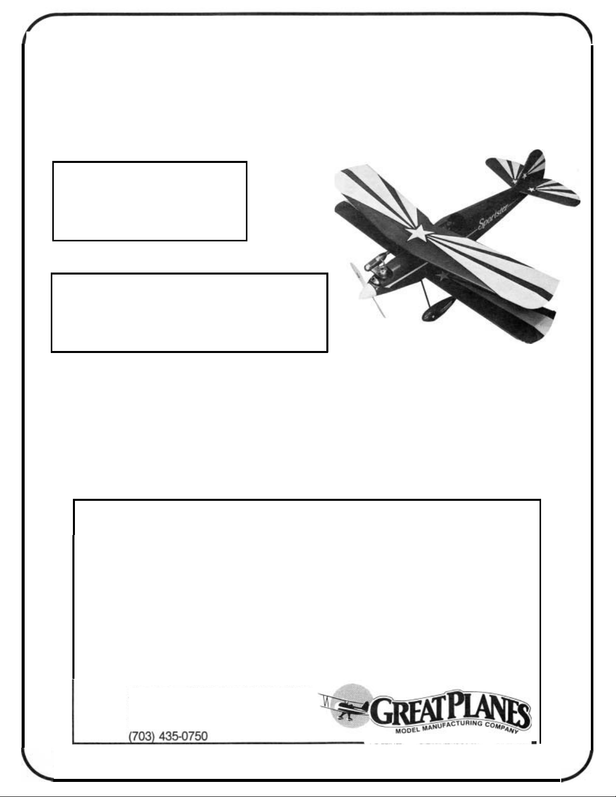
PREPARE THE FIN AND RUDDER
SECTION
Sandthe forwardand rear sectionsof the fin
sary for a good fit. Working over the plans, glue the fin section
pieces together. Sand both sides of the rudder.
CUT THE HINGE SLOTS IN THE FIN AND RUD
DER; CUT OUT RUDDER FOR JOINER CLEAR
ANCE
Draw centerlines down the trailing edge of the fin
and the leading edge of the rudder. Mark and cut the hinge
slots. Two hinges are used above the stabilizer. The third hinge
should be just below the stab and above the tail wheel strut
tab. Cut out part of the rudder leading edge for elevator joiner
wire clearance. Wait to shape the leading edge until the hole
is drilled for the tail wheel tiller arm later.
if
neces
-
-
-
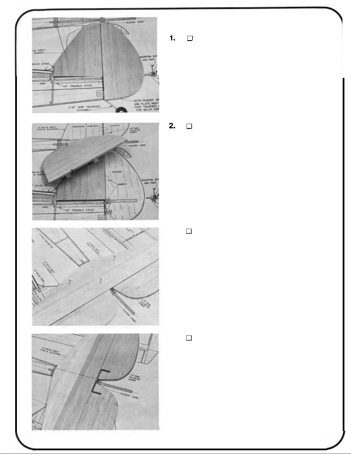
3.
the stab
sides of the stab and elevator halves.
4.
the stab and a centerlinedown the leadingedges of the elevator
halves. Mark the center of the elevator joiner wire. Align the
stab, elevator and joiner wire and mark the hole locations for
the joiner wire arms on the centerline of the elevator leading
edge. Drill the holes.
GLUE STAB PARTSTOGETHER; SAND THE STAB
AND ELEVATORS
Check the fit and sand the forward and rer parts of
so
they fit together well. Glue them together. Sand both
DRILL HOLES IN THE ELEVATOR HALVES FOR
ELEVATOR JOINER WIRE
Draw a front to back centerline down the top side of
2
Page 3
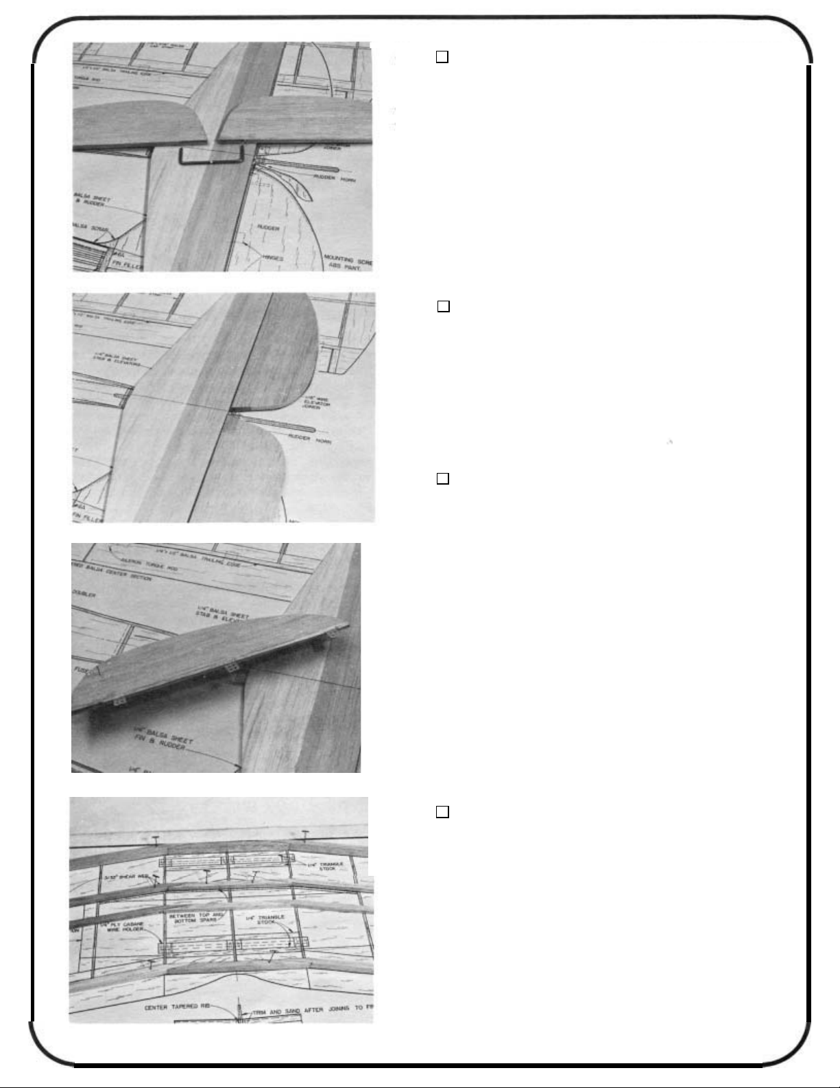
5.
the hole
the leading edge of the elevator.
GROOVE OUT THE ELEVATORS
WIRE CLEARANCE
Cut a groove in the elevator leading edge inside of
so
when the joiner wire is installed it will be flush with
FOR
Do
both elevator halves.
JOINER
6.
elevator halves. Check to make sure that this assembly is
aligned properly. Bend the joiner arms
fit.
DO NOT GLUE THE JOINER WIRE TOTHE ELEVATOR
HALVESUNTILAFTERTHE PIECESARE COVERED LATER.
7.
halves as you did with the fin and rudder. See the plans for
locations. Shape the leading edges of the elevator halves to a
V’.
READ THIS FIRST BEFORE YOU START BUILDING THE
WING PANELS: It is very important that you build straight wings
with nowarps or twists or you will get some flying characteristics
you didn’t expect! Bevery careful when you align the ribs, spars,
leading edges, trailing edges and sheeting at the various steps
below. All these parts should be in their correct positions before
you glue them in place. Hold or pin the parts in place, then
glue. Use the following instructions to help you build the wing
straight and warp free.
TRIAL FIT THE JOINER WIRE
Temporarily install the elevator joiner wire into the
if
necessary for a perfect
CUT HINGE SLOTS FOR THE STAB AND
ELEVATOR
Mark and cut the hinge slots for the stab and elevator
Remember: Anyone can build a wing. Only
can build a straight wing.
BUILDING
Start the top wing by building twospars from 1/4 x
1/4 x 24 balsa, aleadingedge from 1/4 x1/2 x 24 balsa and
a trailing edge from1/4x
on the plan. Cut the parts, fit them together and then glue
overtheplan. The top wing is builtin one piece. You will
build the top wing upside down at first. Use epoxy when
you gluethese pieces together in this step.
3
THE
TOP
1/4 x 24
WING
balsa. U se waxedpaper
a
careful builder
Page 4
2.
top wing rib. Note that the three center ribs have2 extra notches
for the cabane mounting plate. Draw rib alignment centerlines
down the back of the leading edge and the front of the trailing
edge.
PREPARE THE RIBS
Draw a rib alignment line down the center of each
3.
down) over the waxed paper covered plan. Place the ribs on
the spar. Align the ribs at the positions shown on the plans.
Make sure that the three center ribs have the cabane notches
"up"
extra 1/4 x 1/4
drew on the ribs are parallel to the building board. When the
ribs are aligned correctly, and at 90 degrees to the building
board, glue the ribs
with the line on the leading edge. Glue the ribs
edge. Line up the trailing edge line
ribs
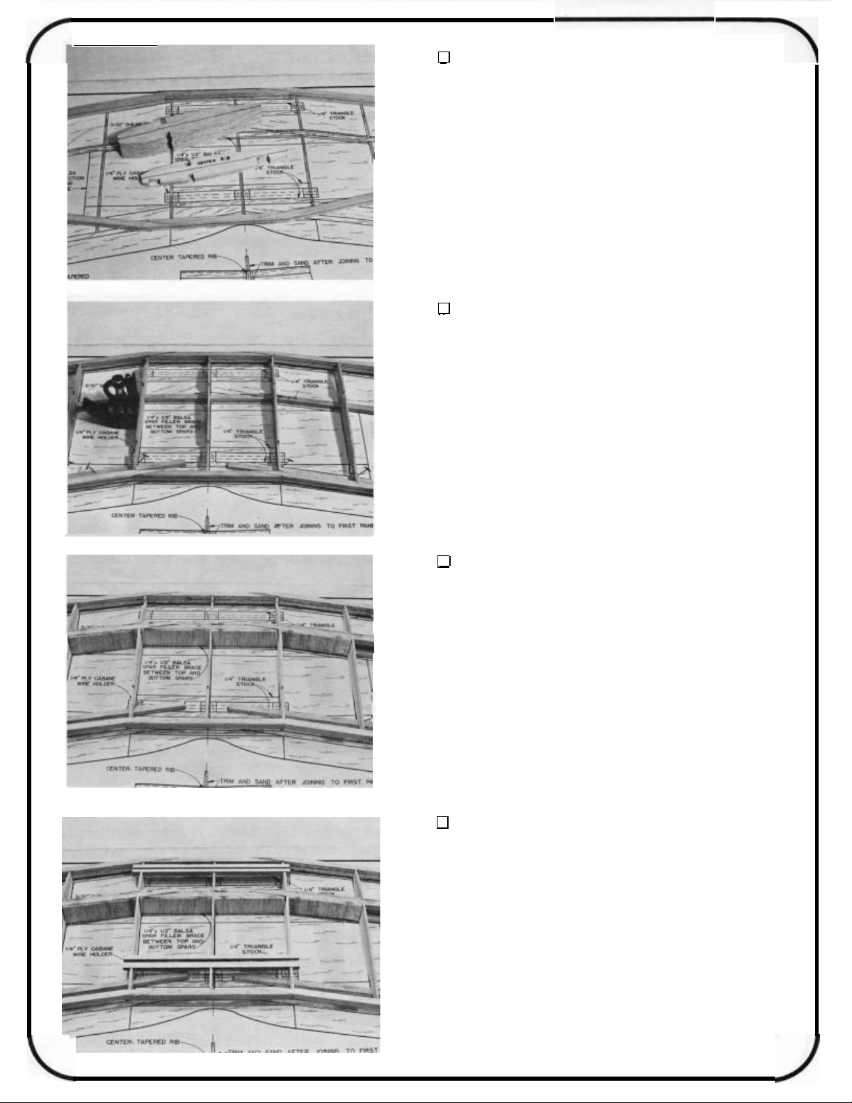
4.
two end center ribs for the 1/4 x 9/16 balsa spar filler brace.
Glue in the 1/4 x 9/16 filler brace pieces from the center rib out
past the spar scarf joint on both sides of the center rib. Glue
in the bottom spar. Now cut shear web pieces from 3/32 x 3
24 balsa to fit between the spars at the rib bays shown on the
plan. The wing should still be shimmed up with the extra spars
throughout the building process. Use epoxy in this step.
ALIGN AND GLUE RIBS, LEADING EDGE AND
TRAILING EDGE TO TOP SPAR
Pin the top spar (the wing will be built (upside
as shown. Shim up the trailing edges of the ribs with the
x
24 spars, making sure the centerlines you
to
the spar. Line up the lines on the ribs
to
the leading
to
the rib lines and glue the
to
the trailing edge.
GLUE IN SPAR FILLER BRACE, BOTTOM SPAR
AND SHEAR WEB
Cut out the area between the spar notches on the
x
I
5.
wire holders with epoxy into the slots in the htree center ribs.
Make sure the cabane holders are flush with the top edges of
the ribs.
4
ADD THE CABANE HOLDERS
Glue in the two plywood 1/4 x 1/2
x
6 1/2 cabane
Page 5
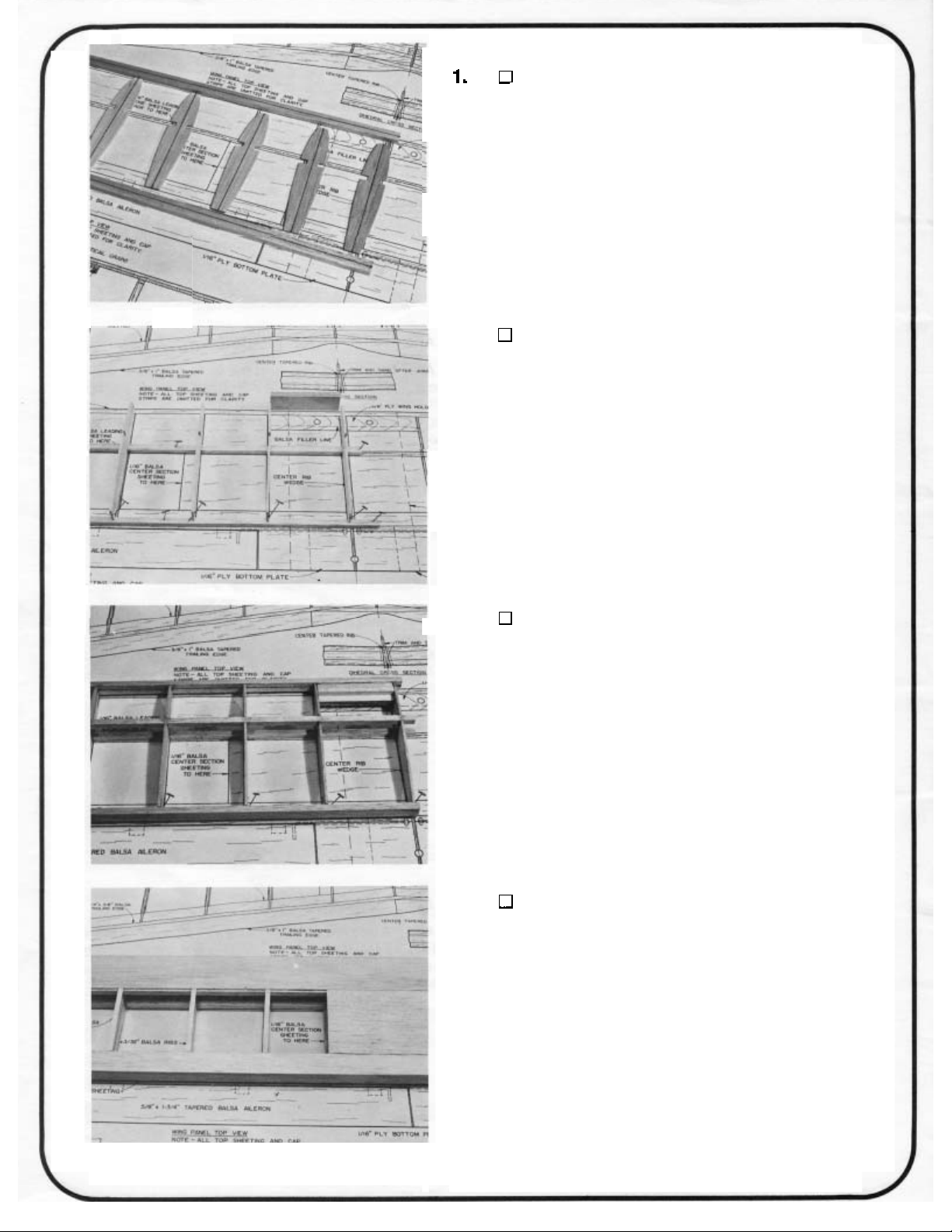
6.
on the 1/16
x
24 trailing edge sheeting and the 1/16x3x15 center section
sheeting. Do not glue the sheeting
you will cut away this sheeting later. Cut cap strips from 1/16
3/16x36 balsa and glue them in place over the rib edges.
ADD THE SHEETING AND CAP STRIPS
Cut the sheeting to fit first then glue in place. Glue
x
2-1/8x24 leading edge sheeting, the 1/16x7/8
to
the cabane holders as
x
7.
down
pieces
on the plan. Glue this 1/4 tri
holder. Also cut tri stock
.
ribs on top ofthe cabane holders. Glue these braces in place.
ADD 1/4 TRI STOCK BRACES
After the glue is dry, turn the wing over and pin it
to
the building board. Use 1/4x36 triangle stock and cut
to
fit along the length of the cabane holders as shown
to
the sheeting andtothe cabane
to
fitoneither side of the three center
\
8.
the1/16
center section sheeting. Glue onthe1/16
ADDTHE REST OFTHE SHEETING
x
Glue on the1/16
x
7/8
x
24trailingedge sheeting and the 1/16x3
2-1/8x24leading edge sheeting,
x
x
3/16cap strips.
15
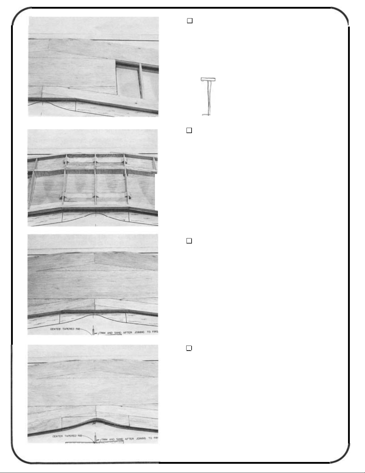
9.
andthe3/8
to
fit first and then glue them in place. Now cut the curve in the
center trailing edge as shown on the plan and in the photo.
5
ADDTHETRAILINGEDGE
x
Addthetapered3/8
x1x
6taperedcentertrailingedgepiece.Cutparts
1x24balsa trailing edgestock
Page 6
BUILDING
line. Also draw centerlines down the 1/4
and the 1/4
bottom to the bottom wing at this point.
THE
PREPARE WING RIBS
Mark all bottom wing ribs with a rib alignmentcenter-
x
1/2x24 trailing edge pieces. There is no top or
BOTTOM
WING
x
1/2x24 leadingedge
2.
the left panel first. Use the extra spar as a shim at the trailing
edge as you did with the tio wing. Pin the bottom spar over the
plans. Align the ribs to the spar, shim up the trailing edges of
the ribs and glue the ribs
hold down block as a spacer for location of ribs #1 and #2.
(Note: These hold downs are the same size as the ones that
glue into the fuselage later.) Do not glue the hold down block
in place yet.
3.
(leading edge, trailing edge and top spar). Use epoxy to glue
the hold down in place. Glue the balsa 1/4
the hold down and sand the it
GLUE THE RIBS TO THE SPAR
Build the right and left wing panels separately. Build
to
the spar. Use the 1/4x7/8
ADD LEADING EDGE, TRAILING EDGE, TOP
SPAR, HOLD DOWN AND FILLER
Align the above parts first and then glue in place
x 5/8 x
to
the shapeofthe rib contour.
x
3
3
filler above
wing
4.
ADD THE SHEETING
x
Glue on the 1/16
leading edge sheeting, the 1/16
edge sheeting and the 1/16 x 3
sheeting. Cut cap strips from 1/16
and glue them in place.
6
x 7/8 x
x
15 center section
x
2-118x24
24 trailing
3/16x36 balsa
Page 7
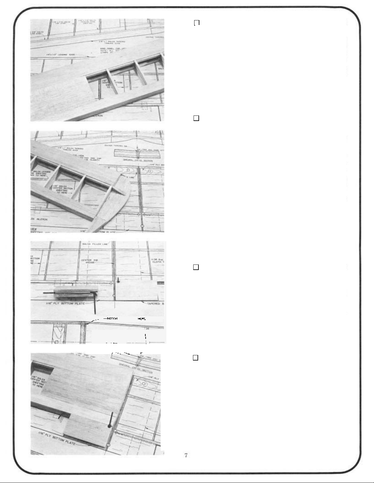
5.
it to the board and glue in the balsa filler on the other side of
the holddown. Sand it to shape. Add the leadingedge sheeting,
the trailing edge sheeting and the center section sheeting. Add
the cap strips. This completes the left wing panel for now. Re
move the panel from the building board when it is dry. Now
build the right wing panel by following steps 1 through
ADDTHE SHEETINGAND FILLER ONTHEOTHER
OF
SIDE
When the glue is dry, turn the wing panelover, realign
THE WING PANEL
5.
INSTALLING THE WING TIPS
-
1.
Do not cut
top and bottom wingslpanels. The tips should be centered on
the tip rib and the leading edge centerline. The wing tips for
the top wing will have to sanded to an angle at the top to fit
against the leading edge. Cut the tip brace pieces from the 114
scrap provided (1/4
lower end of the wing tips, top and bottom. Sand this filler to
shape later after hinging and installing the ailerons. Sand the
leading edge to the rounded shape shown on the plans. Cut
off
the spars and sheeting even with the root rib on the panels.
Cut
the inside
GLUE THE WING TIPS TO TOP AND BOTTOM
WING PANELS
Cut
off
the sheeting and spars even with the tip rib.
off
the leading edge! Glue the wing tips on both the
x
3x11-7/8). Add the filler piece at the
the inner tip filler from some scrap balsa and add to
of
the tip. Shape
it
to
match the ailerons and
tip filler blocks.
INSTALLING THE CENTER
TRAILING EDGE (BOTTOM WING)
I.
panels and down the leading edges of the center sections. Cut
a groove along the centerline in the tapered
balsa center section pieces for the aileron torque rods. Notch
the center sections for backward torque rod arm movement.
Glue the brass sleeves of the torque rods into the blocks with
epoxy. Make right and left assemblies. Also notch the trailing
edge of the wing panelfor forward movementof the torque arms.
MAKE CENTER SECTlON/TORQUE ROD AS
SEMBLIES
Draw a centerline down the trailing edges of the wing
5/8
x
1-3/4x3-1/2
-
2.
rod
so
to move. Glue the rod/center sections to the wing panels up
the centerlines.
GLUE THE CENTER SECTIONS TO THE WING
PANELS
Use vaseline at the ends of the tube of the torque
you don't glue the wire to the wing. The rod must be free
Page 8

JOINING
GLUE THE CENTER RIB TO THE LEFT WING
PANEL
THE
BOTTOM
WING PANELS
With the wing panels
balsa center rib
sure the wider edge of the center rib is down and that the
leading edge and trailing edge are centered on the tapered rib.
5
Use
_
minute epoxy.
2.
it about
block
surfaces.
1/8"
so
that the center rib edges are flush with the wing sheeting
to
the root end of the left wing panel. Make
SAND THE CENTER RIB TO THE WING PANEL
CONTOUR
Rough cut the center rib to the wing airfoil, leaving
oversize. Sand the remainder away with a sanding
"up"
, glue the wedge-shaped
3.
ing and trailing edges of the panels.
make sure the leading edge of the wing is straight. Block up
the wing
slow set epoxy. See the drawing on the plan.
wing is upside down
the wing over and mark the aileron servo well location. Add the
1/16x2
I
4.
JOINTHEWING PANELS; ADDTHEWING PLATES
Join the wing panels upside down. Line up the lead-
Use a straight edge to
7/8"
at the center and glue the panels together using
Remember the
at
this point! When the glue is dry, turn
x
3-1/4
DO
plywoodwing plateto the bottomof the wing.
GLASS THE CENTER SECTION OF THE WING
NOT OMIT
THIS
STEP!
Doingsomay result in a wing failure during flight!
Coat the
minuteepoxy and use
area
where the wings werejoined with
a
4
"
wide strip
of
6
oz.
5
glass or nylon
cloth to reinforce the center joint. Saturate the cloth with
off
epoxy and then wipe
should cover both the top and the bottom
When the epoxy is
any extra epoxy. The cloth strip
of
the wing joint.
dry,
sand the center section lightly
without sanding into the glass cloth.
Page 9
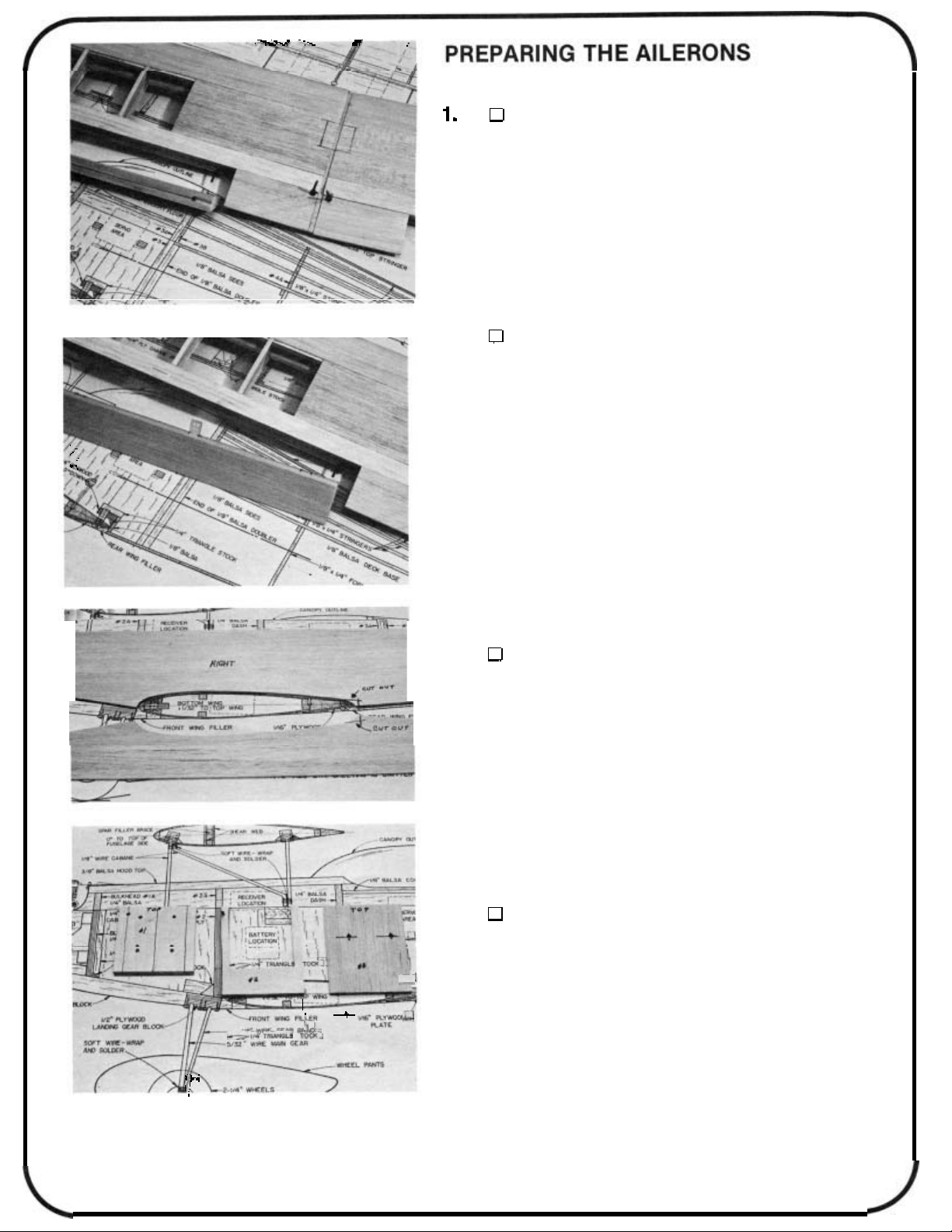
PREPARE THE AILERONS
Cut the aileron stock
length and draw a centerline down the leading edge of the
ailerons. Mark and drill the torque rod holes. Groove the aileron
for torque rod clearance. Make right and left ailerons.
2.
the wing trailing edge. Shape the leading edge
to a
the fit. Final sand the wing tips to match the aileron contour at
neutral. Do not permanently hinge the ailerons until after they
are covered.
CUTTHE HINGE SLOTS; FINAL SAND THE AILE-
RONS
Mark and cut the hinge slots into the ailerons and
“V’.
Temporarily install the ailerons with hinges to check
(5/8 x
17-1/2 tapered stock) to
of
the ailerons
LEFT
BUILDING
,
,
1.
“left”. Cut out part of the wing saddle area at the rear as shown
on the plan.
STOP!
the instructions on installationof 4
this instruction book.
2.
Firewall. Mark the “top” of the firewall (the bottom has a slight
angle). Mark the position of the motor mount. Mark and drillthe
holes for the motor mount
in positions in these holes you drilled. Temporarily place the
mount on the firewall with the screws. Cut the screws
,
back of the firewall
Notch a hole in Bulkhead # 2 for the throttle linkage. Prepare
Bulkhead #3 by drilling holes for the outer pushrod housings.
PREPARE THE FUSELAGE SIDES
Mark the inside of the fuselage sides “right” and
If
you plan to install a 4-cycle engine, read and follow
PREPARE THE BULKHEADS
Locate the 1/4
THE
so
FUSELAGE
-
cycle engines at the end of
x 3
x 2-3/4
4-40
they won’t get in the wayofthe fuel tank.
plywood Bulkhead
screws. Put the 4-40 blind nuts
#1,
off
the
in
9
Page 10
3. D GLUE THE DOUBLERS TO
Using Bulkhead #1 as a spacer, install the 1/8" balsa
doublers crossgrain on the inside of the fuselage sides. Cut the
doubler pieces from 1/8 x 3 x 36 balsa first, position and then
glue in place. Use slow set epoxy or thick cyanoacrylate. The
doubler should extend 1/4"beyond the position of bulkhead #3.
Trim the doublers to the fuselage contour.
Note:
Be careful
to use what is left in the next step.
4. D BUILD THE THREE REAR FORMERS
Use the plans as a guide and cut the balsa to size. Glue the
parts together to make the three formers. Make push rod braces
from scrap 1/8 x 3 x 36 left over from the doubler stock in the
step you just did. The widths of the braces are the same as
that of each of the formers. The braces will be installed when
the pushrods are installed
engine instructions if you plan to install a 4-cycle?
when
Make Formers #4,5 and 6 from 1/8 x 1/4 x 36 balsa.
you
later. STOP!
cut the
THE
FUSELAGE SIDES
doubler
stock
as you
Did you read the 4-cycle
need
D MARK BULKHEAD POSITIONS
Mark the positions of bulkheads #2 and #3 on the
fuselage sides. Also
#2 and #3. Mark the positions of the cabane blocks now if you
wish.
6. D DRILL PUSHROD EXIT HOLES
Mark and drill the holes in the fuselage sides for the
pushrod exits for the elevator and rudder. See the plans for
suggested positions of the pushrods to estimate the hole positions. A piece of brass tubing sharpened on the inside with an
X-Acto knife blade makes a neat, clean angled hole for tubestyle pushrods.
mark
the
position
of
the balsa dash between
10
Page 11

FIT THE WING TO THE FUSELAGE
Pin the fuselage sides together perfectly lined up.
Check the fit to the wing saddle cutout by placing the fuse sides
if
on the wing. Custom sand
wing incidence.
necessary but do not change the
8.
for a better glue joint. Pin the right fuse side to your work surface.
Position the bulkheads correctly (the angle
and glue them in place at
NOTE: The straight edge at the top of the fuselage side is called
the Fuselage Reference Line and will be used later to align the
wing and stab to the fuselage.
9.
down over the top view of the plans. Make sure the flat side is
resting flat on the building board and that the bulkheads are
aligned to the plans. Pin the fuselage in place. Glue the left
fuse side to bulkheads
side is also flat to the building board. Clamp or pin the fuselage
in place until the glue is dry.
SAND FUSELAGE TAIL; GLUE BULKHEADS
AND #3 TO THE RIGHT FUSELAGE
Slightly sand the insides of the fuse sides at the tail
90
degrees to the fuse side.
GLUE LEFT FUSELAGE SIDE TO THE BUL
KHEADS
Align the fuselage sidelbulkhead assembly upside
#2
and # 3 making sure the left fuse
SIDE
is
at the bottom)
#2
-
10.
like the hold down plates in the bottom wing. Glue the front
hold down to Bulkhead
the balsa 1/8
at the rear of the wing saddle. Glue the rear hold down to the
false bulkhead and doublers. Glue 1/4"triangle stock to the top
and bottom of both holddown plates. Use 1/4 tri
11
GLUEINTHE HOLD DOWN PLATES
x
7/8
x
The hold down plates are 1/4
#2
and the fuse side doublers. Glue
x
3/4x3 false bulkhead to the fuse side doublers
3 plywoodjust
x
36 balsastock.
Page 12

GLUE IN BULKHEAD
Realign the fuselage upside down over the plans
and glue the fuse sides
the bulkhead is flat on the building board and that the front of
the bulkhead is facing forward.
to
bulkhead#1
.
Makesurethe top of
12.
of the firewall. Extend the throttle linkage hole through the tri
stock.
13.
thedoublerasshown on the plans. Thedeckbase should butt
to
up
worksurface.Markthe location ofFormers #4, #5 and
Check the fit ofthe formers and glue themtothe deck base
making sure they are
ADD 1/4" TRI BRACING
Add three pieces of 114 triangle stock along the back
GLUE FORMERS TO DECK BASE
Notch the 1/2
the doubler. Pin the deck base over the plans to your
balsadeckbaseatthecornerstoclear
90
degreestothe base.
#6.
14.
overthedeck base. Use a pushrod housing and markthe loca
tion
housing follows asstraight a path aspossiblefrombulkhead
#3 to
the housings
ina tube style pushrods areshown here but other typesmay
be used.
12
PREPAREFORMER BRACES
HOUSINGS
Temporarilyput the fuselage/bulkhead assembly
of
the housing holes inthe former braces. Make surethe
the exit. Drill the holesinthe braces. Temporarilyinstall
to
check your work. Remove the housings.. Tube
FOR PUSHROD
-
Page 13

15.
deck base former
sides of the deck base and the sides of the formers. The deck
base glues to the rear of bulkhead
DO NOT GLUE THE FUSELAGE SIDESTOGETHER ATTHE
TAIL UNTIL THE NEXT STEP!
GLUE THE FUSELAGE TO THE DECK BASE
Gluethe fuselagesides/bulkhead
assembly. Fuselage sides are glued to the
#3.
assembly to the
16.
Use the rudder hinge slot as a guide to placement.
the area open where the tail wheel strut mounting tab will
glue later,
17.
braces to the formers. Rough up the housings with sandpaper
intheareasofBulkhead#3
cyanoacrylate glue, glue both elevator and rudder housings in
place except at Bulkhead
servosare installed.You may trimthe housingsat the exits now.
GLUE THE HINGE/FUSELAGE TAIL;GLUE
THE FUSE SIDES TOGETHER ATTHE TAIL
Glue the rudder hinge just below the stab location.
Keeping
glue the fuse sides together at the tail.
GLUE PUSHROD BRACES TO FORMERS; GLUE
PUSHROD HOUSINGS TO BRACES
Usingthe pushrod
housings as guides, glue the
,thebraces and theexits.Using
#3.
This will be glued later when the
18.
deckbase between former #6 andthetail. Angle
of
the tri stock at the tail for a good glue joint.
13
GLUE IN
Glue 1/4"
1/4
BRACING ATTHE TAIL
triangle stock at the bottom sides of the
-
cut the ends
Page 14

ADD THE LANDING GEAR BRACES
x
Glueinthe grooved 1/2
block at the bottom ofbulkhead
along the frontofbulkhead #2
block.Cut the braces from1/2"
main gear now but do not install until after the model isfinished.
-
Thewider
Note
positioned toward the front of the model for main gear place
ment. The brace fits into the smaller slot.
slot
(groove)inthe landing gearblockis
1-5/16x3
#2.
Addthe 1/2 trianglestock
andthe top ofthe landing gear
x
6stock.Youmaysolderthe
-
1/2landinggear
-
20.
and over the plans, alignthe chin block to the front of the landing
gear block and gluethe chin block to the fuselage. (The fuselage
is notshown aligned
21.
cross
3
x
and work your way back, gluing one piece at a time. Leave the
last section of sheeting out until the tail wheel bracket is installed
later. When the glue is dry, remove the fuselage from your
building board and sand the bottom sheeting to shape.
GLUE THE CHIN BLOCK TO THE FUSELAGE
90
With the fuselage still at
to
theplansinthe photo.)
ADDTHEBALSA BOTTOM SHEETING
With all pins removed from the inside of the fuselage,
-
grain sheet the bottom rear of the fuselage. Use 3/32
24
balsa and cut pieces to fit. Start at the false bulkhead
degrees to the board
x
22.
to
match the plans. Mark the locations of thestringersonformers
3Aand6A by referring
of3A.Glueformer6Bto the frontof 6A.Drawthe location lines
forthe cockpit floor onthe back ofthedashandonthefront
ofthe 3A/3B
14
PREPARE TOP FORMERS 1ATHROUGH 3B
Preparethe fuselage top formers bynumberingthem
to
the plans. Glue former 3B totheback
assembly.
Page 15

23.
and
a slight angle sothe top blockwillmate squarely when glued.
Trialfit the assembled fuel tank.Carve out a section offormer
2Aforfueltank clearance
permanently,plug all fuel lines
lines.
ADDFORMERS 1AAND 2A
Glueformers 1A
2.
Whentheglueis dry sand the tops ofthese formers
and2Ato the
if
necessary.Ifyouleavethetankin
so
balsadustdoes not enter the
tops
ofbulkheads 1
to
24. ADDTHEDASHANDFORMERS3N3B
Pinthe hood top inplace
thedash. Put the cockpit floor inposition
placementofthe dash on the fuseside.Gluethe dash
fuse sides. Do not glue on thehood top yet.Glueformer3A/3B
to the fuselage at the rear ofthe cockpit on top ofbulkhead#3.
todetermine the heightof
todetermine the
to
the
.
25. GLUE IN THE COCKPIT FLOOR
Glueinthe balsa cockpit floorbetween
the dash and former 3A/3Bon thelinesyoudrewearlier.
26.
led into the fuselage. Cut the sheeting out over the cabane wire
holders in the top wing. With the wing level on your work surface
and the bottom side of the wing up, place the cabanes into the
slots
each other. Wrapthe wire bracesto the cabanes with the copper
wire provided. With the cabanes
the bottom (nearest the wing) wire wrapped end of the cabane
on both sides. Then solder the
losing the alignment
SOLDER THE CABANE WIRE
top
The cabanes for the
in the holders. The bent ends of the cabanes should face
to the wing.
wing are permanently instal
90
degrees to the wing, solder
top
wire wrapped end without
-
.
15
Page 16

27. PREPARE SMALL CABANE BLOCKS
Clearance holes will have to be cut in the small
cabane blocks for cabane wire clearance. Place the blocks on
the cabane wire ends. The blocks should line up with the top
of
the fuselage. Clamp the blockstothe fuselage.Do
the
blocks
yet!
not
glue
28.
fuselage side) parallel
be right side up. Place the top wing onto the cabanes. Line up
the top wing to the work surface and the fuselage as shown in
the drawings. Distance A should equal distance A, B should
equal B and C should equal C. When the top wing is properly
aligned, mark the positions of the cabane brace blocks in the
fuselage. Use slow set epoxy and glue the blocks in place. Fill
in the areas around the wires in the blocks with epoxy. Glue on
the 1/16 x 112
the alignment before the glue sets up.
When the glue is dry,
in the wing with silicone. Put car wax or similar material on the
cabane wires and placethe wing backon the cabanes. Remove
the excess silicone that may ooze out
that you added makes a good seat for the wires and cuts down
on vibration. After the wing is covered later, you will attach the
top wing to the cabanes with the aluminum plates and the #2
x
3/8 screws provided. Ttie plates should be flush with the wing
sheeting. Note
ment when you apply the silicone to the cabane slots. The wires
should still touch the bottom of the slots in the holders; the
silicone fills in around the sides of the wires in the slot.
ALIGN THE TOP WING TO THE FUSELAGE
Align the Fuselage Reference Line (top side of the
to
the work surface. The fuselage should
x
1-112 plywood cabane brace caps. Recheck
fill
in the
slots
in the cabane wing holders
of
the slot. This silicone
-
Make sure you do not disturb the wing align
-
29.
0
to be twisted slightly
easy to twist the balsa as required,
both pieces of the balsa sheets. Place one end in a vise and
twist the other end somewhat more than is required. Hold or
clamp this end until the wood dries (about 15 minutes). Note
that the twist inthe right piece
PREPARETHEBALSAHOOD SIDE PIECES
-
The 1/4x 1
3/8 x 17-1I2 balsa hood side pieces need
to fit the front of the fuselage. To make it
"
paint"some ammonia on
is
oppositethat of the left piece.
30. GLUE ON THE HOOD SIDE PIECES
so
so
they
they
Sand the bottoms of the hood side pieces
will mate squarely with the fuselage sides. Notch out the side
fill
pieces for cabane wire clearance. You can
holes later. Glue the side pieces from the front of former 3A/3B
to beyond former 1A i n the following manner.To preventatwisted
fuselage, glue both pieces at the same time, a little at a time,
starting at former 3A/3B. Also make sure the hood side pieces
extend outside former 3A/3B and the fuse sides slightly
can be sanded to contour later.
16
in these notched
Page 17

31.
top of the formers
SAND THE TOPS OF THE HOOD SIDE PIECES
Sand the tops of the hood side pieces flush with the
so
the hood top will mate squarely.
32.
glue it on as it is a little difficult to sand in that area after the
hood top is glued on. Glue the hood top in place. Trim the hood
sides at the cockpit as shown on the plans.
33.
the back of the fuselage. Mark the position of former 6A/6B.
Remove the stab. Glue 6A/6B in place.
GLUE ON THE HOOD TOP; SAND HOOD SIDES
AT COCKPIT
Trim the hood top at the cabanes first before you
ADDFORMER6A/6B
Pin the stabilizer in place
so
the stab is aligned with
34.
stringertofitbetweenformers3A/3Band6A/6B.Gluethe
stringer in place.
-17-
GLUE ON TOP STRINGER
Use the 1/4
x
1/4x16 balsa stock and cut the top
Page 18

35.
a straight edge alongthe top stringer. Placeand gluetheformers
so
they mate with the top stringer and and are centered from
side to side.
ADD FORMERS 4A AND 5A
Locatethe positionsof formers4A and 5A by placing
36.
to fit. Start by gluing at 6A/6Bfirst, checking with a straight
edge first, and then gluing
37.
depending on your engine) for the throttle linkage clearance.
Using
excess epoxy at the chin block joint. Carve and rough sand the
hood top, hood sides and chin block
side pieces. The next few photos will helpyou
needed. Don’t take
next to see where you need clearance.
ADD THE TURTLE DECK STRINGERS
x
Use the 1/8
PREPARE AND GLUE IN THE SIDE NOSE
BLOCKS; FINAL SAND THE FUSELAGE FRONT
Groove the inside of the nose side block (right or left
5
minute, glue the nose side blocks in place. Remove
1/4x16 balsa stock and cut stringers
to
5A, 4A and 3A/3B.
to
the shape of the nose
to
see the shape
too
much
off
until you mount the engine
38.
provided. Place the engine on the mount. Cut away areas of
the engine compartment
Check for binding of the throttle arm. Mark and drill the holes
in the mount for engine mount bolts. Tap the holes for bolts and
nuts or use self
The engine has no down thrust or right thrust.
18
TEMPORARILY MOUNT THE ENGINE TO THE
Temporarily install your mount with the 4
so
the engine rests flat on the mount.
-
tapping bolts to hold the engine on the mount.
-
40 bolts
Page 19

39.
of the 2
washer should extend 1/16 to 1/8 inches forward of the filler
block. Cut away areas on the block for engine clearance. The
placement of these parts depends on what brand spinner you
will use. Inspect your spinner backplate and locate the block
accordingly. When you are sure of the placement, glue the crossgrain nose filler block in place. Sand the front of the nose
the frontofthe filler block and the front of the nose side pieces
are even. Glue the 1/16 plywood spinner ring in place on the
filler block using your engine and spinner backplate as a guide
for placement. The engine shaft should be centered in the hole
in the spinner ring.
ADD NOSE FILLER BLOCK AND SPINNER RING
Using your engine as a guide, locate the placement
-
1/4 x 2-1/4 x 1/2 nose filler block. The engine thrust
so
40.
along the bottom sides of the engine compartment and behind
the filler block. Use 3/8 x 12triangle stock for this step. Custom
fit these pieces
Now sand and carve the nose of the fuselage to the shape of
the spinner ring.
ADD 3/8
TO
Remove the engine and add the 3/8 triangle stock
TRI
STOCKTOTHE NOSE; SAND NOSE
SHAPE
so
they gluetothe firewall and nose filler block.
.
41.
the plan for placement. Drill a hole in the bottom of the engine
compartment just in fron of the firewall for fuel drainage.
DRILL FUEL LINE HOLES AND A DRAIN HOLE
Drill the holes in former 1A for the fuel lines. See
42.
you did before by making sure the Fuselage Reference Line is
parallel to the work surface. Now align the stabilizer to the
fuselage in the following manner: A
the stab bed at the end of the fuselage. Line up the stab centerline to the fuse centerline. B
point at the centerof the top of the firewall area. Each measure
ment should be the same. CMeasure from each stab tip to
the work surface. Each measurement should be the same. D-
To
make sure you have zero degrees incidence,measure from
the center of the leading edge to the work surface. Measure
from the center of the trailing edge to the work surface. These
distances should be the same. When the stabilizer is aligned,
do not glue in place but go on to the next step.
19
ALIGN THE STABILIZERTOTHE FUSELAGE
First align the fuselage to your flat work surface like
-
Draw a centerline down
-
Measure from each stab tip to a
-
Page 20

43.
up the angle of the top stringer. Then sand them
of the stringers. Shaping and sanding is easy if you tack glue
scraps of balsa the thickness of the stab and fin to the fuselage.
Trim the scrap even with the fuse sides and stringer line, then
tack glue the blocks in place and razor plane and sand them
to
shape. When ready, break the blocks loose and remove and
discard the scrap. Use epoxy and glue the stabilizer to the
fuselage. Glue the fin to the stab at
aligned on the stab centerline. Glue the fin
degrees to the stab and aligned on the stab centerline. Glue
the prepared fin filler blocks in place with
move excess epoxy.
PREPARE THE FIN FILLER BLOCKS; GLUE ON
THE STAB, FIN AND FIN FILLER BLOCK
to
Prepare the fin filler blocks by cutting them
to
the contour
90
degreestothe stab and
to
the stab at
5
minute epoxy. Re
pick
90
44. ADD DORSAL FIN AND FILLER PIECES
Use scrap balsa and custom make the dorsal fin
piece and filler pieces. Glue the dorsal fin
top stringer. Glue the filler pieces between the top stringer and
the next stringer on each sdie of the dorsal fin. These filler
pieces are used to anchor the covering material later.
to the fin and
1/4"
-
45.
plans. Use
piece of bottom sheeting. Mark and drill the hole for the tail
wheel tiller arm in the rudder. Also groove the rudder leading
edge below the hole for the nylon bearing clearance. Shape
the leading edge of the rudder
FINAL
1.
by placing the fuselage reference line parallel
face. Align the bottom wing tothe fuselage bymakingthe follow
ing measurements: A-Center the wing side to side in the sad
dle. The distance from the fuselage side tothe wing tip on each
side should be the same. &The wing tip to stab tip distance
should be the same on both sides. &Wing tip to work surface
and top wing tip to bottom wing tip distance should be the same
on both sides. D
+
1/32"to the top wing. This means that the leading edge of
the bottom wing should be 1/32" closer to the top wing than
the trailing edge of the bottom wing is. When the wing is in the
correct position, mark the fuselage and wing
the wing exactly the same again.
ADD TAIL WHEEL STRUT; FINISH RUDDER
Glue the tail wheel strut in place as shown on the
5
minute and clamp the tail until
to
a
"V"
ASSEMBLY
ALIGN THE BOlTOM WING TO THE FUSELAGE
AND TOP WING
Align the fuselage upside down
-
The bottom wing has a positive incidence
dry.
Add the last
.
to the work surface
to
the work sur
so
you can position
of
-
-
-
20
Page 21

2.
aligned to the fuse, drill two
hold down plates in the leading edge of the wing and one hold
in the trailing edge of the wing. Drill the rear hole at an angle
so
the bolt head will rest flat on the trailing edge. Drill these
pilot holes through the hold downs in the fuselage at the same
time you drill through the wing. Remove the wing. Drill and tap
the holes in the fuselage hold downs for
bore the leading edge holes in the wing
rest flat against the hold downs in the wing.
DRILLAND TAP WING BOLT HOLES IN THE WING
AND FUSE
Withe fuse aligned to the work surface and the wing
11/64
pilot holes through the wing
-
20
1/4
bolts. Counter-
so
that the bolts will
3.
on the bottom of the wing even with the fuselage sides. Cut the
fairings to width. Sand to shape by placing sandpaper on the
wing and working the fairings back and forth.
4.
wing bolt heads to pass through. Install the wing bolts and glue
the fairings in place with
any epoxy on the wing bolts and not to glue the wing to the
fuselage!When the glue is dry, sand the fairings to the fuselage
contour.
SAND THE WING FAIRINGS TO SHAPE
Prepare to install the wing fairings by drawing lines
GLUE THE FAIRINGS
THE FUSELAGE CONT
Drill holes through the fairings large enough for the
5
minute epoxy. Be careful not to get
PLACE; SAND THEM TO
IN
OUR
5.
want to add a pilot, paint the cockpit area and/or add an instru
ment panel. Fuelproof the engine compartment by coating all
the balsa and ply parts with resin or epoxy. Now final sand the
entire model.
21
FINISH COCKPIT AREA: FUELPROOF FUSE;
FINAL SAND MODEL
Finish the cockpit area any way you wish. You may
-
Page 22

6.
hardwood into the radio compartment. Install the rudder,
elevator and throttleservo directly to the hardwood rails or install
the servo tray that comes with your radio. Position the battery
and receiver (wrapped in foam rubber for protection) as shown
on the plan. Install the
wires or tubes into the pushrod housings for the rudder and
elevator. Also install a cable type pushrod and its outer tube for
the throttle linkage.
INSTALL RADIO COMPONENTS
Glue servo rails made from scrap plywood or
switch. Install the inner pushrod
on/off
7.
enough of the wing sheeting, center rib and root ribs to allow
the placement of the servo as deeply as possible inside the
wing. Glue hardwood rails (from scrap) as shown in the photo
or use the tray that came with your radio. Drill small pilot holes
in the rails for the servo screws.
8.
so
no binding occurs with the other servos. Installthreaded wire
pushrods with
to the aileron torque rod arms with the nylon connectors, wheel
collars and screws provided and clevises of your choice. This
end of the linkage is therefore adjustable.
CUTTHE SERVOWELL IN THE TOP OFTHE BOT
TOM WING
The well is located directly behind the spars. Cut out
INSTALL AILERON SERVO AND LINKAGE
Mount the servo as deep into the wing as you can
“Z’
bends at the servo. Connect the pushrods
-
9.
bly into the slots in the bottomofthe landing gear plate.
Place
straps over the brace and mark the hole positions on the
landing gear plate. Drill pilot holes for the
Put the screws in place.
10.
gine mount unless you already have. Attach the enginel
muffler to the mount.
INSTALL
Place the soldered maingear and braceassem
3
landing gear straps over the main gear and
INSTALLTHE ENGINE AND MUFFLER
Attach the muffler to the engine. Install the en
THE
MAIN GEAR
#2
x
3/8
screws.
11.
ready. Assemble the tank per manufacturer’s directions.
Feed extra long fuel lines through the front of former 1A
2
into the tank compartment. Attach the lines to the tank
and pull the tank into position. Cut the fuel lines to length
and attach them to the engine.
12.
while you are covering. Make sure the model is all final
-
sanded and clean (use a tack cloth or rag to pick up any
dust). Use heat shrink covering material and cover your
Sportster Bipe. Follow the instructions available with the
covering. When the model is completely covered, reinstall
INSTALLTHE FUELTANK
if
Install the tank now
COVERTHE MODEL
Remove any equipment that will be in the way
you haven’t donesoal-
Page 23

13.
INSTALL ALL CONTROL SURFACES AND
CONTROL HORNS
Flex the hinges back and forth a few times and
then glue the hinges into the rudder and fin slots; at the
same time glue the tiller arm of the tail wheel into the
rudder leading edge. Lightly sand both surfaces of the
hinges, put epoxy into each hinge
2-56
place the hinge in place. Use
and attach the nylon horn
to
the rudder over the tail wheel
screws and backplate
slot and
tiller arm position for extra support. Glue the elevator joiner
to
wire
the elevators. Glue the hinges to the elevators and
stabilizer in the same manner as above. Attach the nylon
to
elevator horn and backplate
2-56
elevator with
screws. Glue the aileron torque arms
the bottom of the right
into the ailerons as you glue the hinges into the ailerons
and wing trailing edge.
14.
INSTALL THE CANOPY
Cut the canopy on the cut lines scribed in the
plastic. You can dye the canopy using Rit dye. Follow the
instructions on the box. Remove the canopy from the dye
when the desired tint is achieved. Glue the canopy to the
fuselage with cyanoacrylate glue. Seal the edge with strip
ing tape.
15.
ASSEMBLE THE WHEEL PANTS
Cut and trim the wheel pant halves on their
parting lines that you find on the inside of the pants. You
-
can score this line with an X
Acto knife and break on the
line or simply cut on the line with a knife.
Sand the edges of the wheel pants smooth. An
to
do
easy way
this is to lay your sandpaper down on a
flat surface and move the pants over the sandpaper. This
way you are assured of a straight, flat edge when you
finish.
Cut a starter hole in one half of each pant in
the area of the wheel opening
to make it easier
to
cut out
the opening later after the halves are glued together. Cut
the starter hole at the join line. Using cyanoacrylate (in
stant glue), join the two halves together. Note that there
to
is a right and a left half
the wheel pant. Make sure you
have a good fit before you glue the two halves together.
When the halves are joined, sand lightly along the join
line on the outside of the pant
to get a smooth appearance.
16.
side of each wheel pant. Drill a clearance hole at this
location for your gear wire or axle bolt. See Figure
Do this by temporarily placing the wheel pant on the gear
Position the pant
level or in the correct position for your model. Mark the
positionof the brass plate on the gear and on the outside
of the pant. Remove the wheel pant! Solder the brass
plate
solder the other brass plate in the same manner.
of the wheel pant opposite the brass plate on the gear,
Temporarily put the wheel pant back on the gear to find
this position. The ply plate is used as a backup plate for
the brass plate
up. When you have the correct positions for the ply plates,
use
wheel pants. Let the ply plates dry.
pants.
holes through the wheel pants and the ply back up plate
for the
attaching the screws provided, wheels and wheel collars
to hold the wheels
remove the assembly from the gear. See Figure
-
’
-AXLE
HO
Figure 1
MOUNT THE WHEEL PANTS AND WHEELS
Mark the position of the axle hole on the innei
Mark the positionof the brass plateon the gear
so
it does not touch the ground and
to
the gear using Sta-Britesilver solder. Positionand
1/8
Posiiton the
so
do a good job of lining these two plates
5
minute epoxy and glue themtothe inside of the
plywood plate on the inside
Drill the axle hole through the ply plates in the
Using the brass plate as a guide, drill two pilot
#2
x
3/8”
screws.
Trial fit the wheel pant assembly
to the gear by
to the gear. If all is in the correct position,
LANDING GEAR
WHEEL
WHEEL
PANT
COLLARS
TAPE
L
E
1.
is
2.
Use your wheel and measure and mark the
to
area
be cut out of the pant for the wheel opening. Cut
out this area.
Findthe tape locations on the insideof the pant
in Figure
60-100
coarse sandpaper and sand the
1.
Use
areas where you will put the tape.
Reinforce the inside of the wheel pants with
fiberglass tape. Cut the tape into one inch squares. You
should have eight pieces of tape when you finish cutting.
5
Use
minute epoxy and piece of tape at each of the
places you sanded before. Let the tape hang out of the
off
wheel opening. Cut the excess
when the epoxyis dry.
BRASS PLATE
WHEEL
Figure
2
Paint the wheel pants. First, sand lightly with
wet/dry
320-400
sandpaper but use it dry. Use
K&B
or automotive primer. Sand the primer after it is dry. You
to
need only
sand the primer lightly. Put on the final coat
of paint. Spraying works the best for the final coat but
brushing the paint will give you good results also.
23
primer
Page 24

18.
of the fuselage and attach it
NOT cut the antenna wire!
19.
rudder pushrods
other ends maybe attached by "
and does not need
end of the throttle cable and attach it
arm. Attach the other end of the cable
with a connector of your choice. The servos and linkages
should not interfere with eachother. Set the control surface
throws as shown on the plan.
SPORTSTER BlPE FOUR-CYCLE CONVERSION INSTRUCTIONS
“4
the 4-cycle fun. Whether you wanttojust “putter” around the sky, or loop, roll and snap, the Sportster/4-Cycle
combination is unbeatable!
EXTEND THE RADIO ANTENNA
Run the antenna out of the radio compartment
to
the front of the fin. DO
CONNECT ALL LINKAGES (PUSHRODS),
CONTROL SURFACES, CHECK RADIO OP
ERATION AND SET THE THROWS
Attach clevises to the ends of the elevator and
so
they are adjustable at the tail. The
Z"
bends or other method
to
be adjustable. Attach a clevis to the
to
the engine throttle
to the throttle servo
The Sportster Bipe is a natural for 4-cycle experimentation. The unique looks of the Bipe just screams
-
Cycle” and the lightweight air-frame and symmetrical airfoil means the Sportster design will make the most
20.
on the plan.
around until the model balances at the point shown.
additional balance weight is needed, add lead weights
the nose ortail to get the proper balance. Range check
your radio at your flying site as per your manufacturer’s
recommendations. Recheck your wing and stab align
ments. Makesure the rudder is90degrees to the fuselage.
Check
ment is in good condition.
RANGE CHECK
CHECK THE CENTER OF GRAVITY; RE
CHECK ALL ALIGNMENTS
Your model should balance at the point shown
If
it doesn’t, move the battery and/or receiver
to see that all hardwareis secure and that all equip
YOUR
RADIO SYSTEM;
21. TRIMTHEMODEL
Make your first flights, with the help of an experi
enced modeler/flyerifthis is your first model. The model
to
may need some trim changes or adjustments
surfaces after the first flight. Adjust the control surfaces
at the clevises until the model flies correctly.
the control
-
If
to
-
-
-
of
-
cycle engines offer many benefits-their quiet, realistic sound is pleasing to modelers and non-mod-
Four
elers alike. Hightorque allows the use of high pitch or large diameter propellersfor a newstyle of flight characteristics.
They are also very fuel efficient for economical operation.
-
On the other side of the coin, 4 cycles are larger and heavier than equivalent power 2
means some special care must be taken
farther back than normal. We’ll help you with that task with these instructions.
CHOOSING YOUR ENGINE
It’s
difficulttosay what the optimum engine size is for your Sportster Bipe. The old rule of thumb was
to
choose a 4-cycle engine with 1-1/2 times the 2-cycle displacement for equivalent horsepower. But recent
advancements by engine manufacturers have brought the power of 4 cycles way up and the weight of the engines
down. One good example is the Enya .46 Four Cycle. This engine weighs just a fraction more than most 2
.40’s and it produces comparable power and thrust.
For the Sportster Bipe, you can choose between a .40 and
flight performance. A .60 provides plenty of thrust, but with a significant increase in weight and size. The
fit, but it’s going to betight. Seethe full size drawings followingof the Enya .46 and the
A
CHOOSING
-
cycle use. The Hayes AL-40 will fit the Enya .46. The AL-60 will fit the OS FS-61. Tatone produces aluminum
for 4
mounts that are predrilled for individual engines.
gives a beam mount system that is extremely rigid but makes removal of the mount a little more cumbersome.
BUILDING PROCEDURE
MOUNT
Low weight and rigidity are important in 4 cycle mounting. Hayes and Tatone both make good mounts
Both brandsare lightweight.To improve rigidity, we recommendinstalling afront bulkhead.This essentially
to avoid a nose
-
heavy airplane, such as moving the firewall and radio
.60 size four cycle. A .40 will give docile
0SFS
-
61mountedin the Bipe.
cycles. That
-
cycle
.60 will
Following are new steps that refer
to
book. Refer
part of this book.
BUILDING THE FUSELAGE
these steps here as you build your model. Step numbers here refertothe step numbers in the front
to
4
cycle installation
24
to
replace the steps in the front part of this
Page 25

MOUNT
Page 26

HAYES
AL-60
Page 27

2.
position. The thrust line of the engine should be in the same position as shown on your plan. Drill holes and install
blind nuts. Temporarily install mount and trim the mount bolts that extend into the tank compartment. Drill hole for
throttle pushrod to carburetor, making sure the throttle pushrod does not interfere with tank.
PREPARE
Mark the top of the firewall. Mark the centerline of the engine on the firewall and center the mount in
THE
FIREWALL
Next bolt the engine
leaving sufficient room for engine and/or carburetor clearance. Make sure you don’t put in any right or left thrust.
Then measure the distance from the back of the firewall tothe thrust washer. To do this, place the engine
and mount on a flat surface and put a straight edge across the thrust washer. Measure back from this straight
to
edge
measuring this distance
of the model.
the back of the mount. This is distance
so
I
2
-
CYCLE ENGINE
GREAT PLmES MOUNT
AND
to
its
mount.Ifyou use a Hayesmount, position the engine as far back as possible
“B”.
Refer to the drawings and the chart shown here. We are
we can determine how far back to move the firewallsothe engine will fit into the nose
Figure
1
.
I
4-CYCLE ENGINE
&D
HAYES MOUNT
I
Now let’s figure out how far back tomove the firewall from the normal 2-cycle position. We have already
“A”
figured out for you the
used into account.
to
distance
the above measurement.
Distance
If
B
(length of
your4cycle
engine and
distance of the Sportster Bipe which is 3-3/4”. The chart below also takes the spinner
you use a different spinner then mentioned, just measure your backplate depth and add that
Distance
A
(length of 2cycle
Minus
engine/mount and
spinner back plate)
mount
SPORTSTER
Basically all we’ve done here istomeasure how long your new mount and engine is, allow for some
spinner backplate space, and subtract the distance shown on the plan
The result gives you the distance you have
BIPE
B
B
B
3-3/4”
3-29/32“
3-7/8”
to
move the firewall back. See Figures 3 and 4 also.
(CB
Spinner)
(Dubro Spinner)
(Goldberg Spinner)
?
(Distance to
Equals
move firewall
back)
(A)
from the distance you measured
?
?
?
(B)
.
27
Page 28

Let’s do an exampletoshow this. Refertothe drawing showing the OS FS-61 in the Bipe. We are going
to use a Goldberg Spinner. Our “B” measurement is
5-1/8
rear of the mount. By looking at the information in Chart
from our distance B. The result is
1-1/4.
We move the firewall back
(measure from the front of the thrust washertothe
1,
we know that we havetosubtract 3-7/8 (Distance A)
1-1/4.
Example
:
B
-
A
?
5-1/8
-
3-7/8
1-1
Work Area: Your
Your
B
A
Move Firewall
Back
HARD SCRAP BALSA
3.
MARK NEW FIREWALL
POSITION;
Mark the new position of the firewall on the inside
parallel
to the front of the fuse sides. Using the firewall as a spacer, install the
the inside of the fuse side. Custom cut these pieces
TO
BOTTOM
SIDE VI
OF
FIREWALL TO FILL ANY GAP
1/8“
(VERTICAL GRAIN)
EW
GLUE ON DOUBLERS
of each Fuselage side. Make sure vour line is perfectly
to
fit. Do not glue the firewall in at this time. Use epoxy glue
BALSA DO
UBLER
I’
1/8
balsa doublers crossgrain on
Figure
3
or thick CA to glue the doublers in place. The doubler should extend past Bulkhead #3. Carefully trim the doublers
to
the fuse side shape.
11.
GLUE FIREWALL IN CORRECTED POSITION
Draw the corrected bulkhead #1 position on the top view of the plans. Next still working over the plans,
,
glue bulkhead #1
5)
scrap balsa filler blocks, vertically grained, forward of bulkhead#1. Sand the blocks flush with the fuse sides.
1/4
Add
37.
balsa filler below the firewall later when you remove the fuselage from the building board.
GLUEONTHE BALSA NOSE SIDE PIECES
the firewall, in place. Then add 3 / 8 (or
Check for adequate width clearance for your engine.
to cut away part of the
need
can custom make 3 / 8 balsa sides and
1/2
nose side pieces and 3 / 8 scrap filler pieces in the engine mount area. Or you
1/8
filler pieces as shown in Figure5.Now follow step 37 in the front of
1/4
depending on your mount width-see Figures 4 and
If
your 4-cycle and mount is over
2-1/4
wide, you’ll
this book and glue in the side pieces.
if
Next,
1/8
plywood. Once the front bulkhead is epoxied in, drill the front of this bulkhead mount for 4-40 bolts. Then tap
the mount and install 4
desired, add a front bulkhead as shown on the full sized drawings. Make this bulkhead from
-
40 bolts.
I
I
\
\
Figure
4
FUSFl AGF TOP VlFW
28
Page 29

IF
MWNT
WIDTH
EXCEEDS T HE SPACE AVAILABLE
-
. .
Figure
5
GENERAL INFORMATION
of
Center
gravity:A nose heavy airplanecan be a problem! Make sure you check the CG locationduring
construction with the radio components installed. You may need to put the radio as far back in the compartment
as
possible. This will avoid having to carry tail weight.
Props:Always start with the manufacturer’s instructions (especially for break in) for prop selection. Read their
4
instructions carefully because
at a lower RPM and produce greater torque than equivalent displacement 2
cycles use entirely different diameter and pitch propellers because they operate
-
cycles.
You may find that after operating your sportster with recommendedprops that you’ll want to experiment
with other props. It is amazing how much you can change flight characteristics of a model by changing props.
If
you are looking for higher flight speeds from your Bipe than you are getting from the average recom
mended prop, consider reducing the diameter and/or blade area slightly and increasing the prop pitchtobring the
to
RPM back
x
5, 12 x 6, 11x7, 11x6, 10
13
performance. Larger props will provide slower speeds
racy Sportster. For faster speed, we found that a 10
the normal range. For example,with our Enya .46 equippedSportster Bipe,the instructions recommend
x
6,
10 x 7 or 10
x
8
props. We started with an 11x7 propeller which gave us fair
...
fine for big biplanes
-
1/2x7-1/2 propeller added approximately 10 mphtothe
...
but not what we wanted from our
straight and level flight which help make vertical maneuvers crisper due to a faster entry speed. There is a trade
x
off, however, as the engine idle was somewhat higher due to the lower mass of the wood 10-1/2
Four
-
cycles like flywheel weight from large diameter props. This made the plane land a little faster than with the
x
6. The prop we used was a prop designed for .60 size pattern engines, a Max Daily (Radio South) propeller.
11
A similar prop is also available from DW Products. Their addresses are:
.
7-1/2 propeller.
-
Radio South DW Products
180
E.
Burgess
Pensacola, FL 32503
Fuel Tank: For simplicity, we recommend a
2
line tank for your Sportster Bipe.Ifyou can’t easily reach the fuel
5634 Crystal
Ct.
Santa Rosa, CA 95404
line for fueling purposes, you might consider using one of the Dubro fueling valves. This will save extra plumbing
that could leak or cause problems. Most 4 cycles have a small enough venturi that muffler pressure is unnecessary.
Don’t forget the crankcase drain line. A lot of excess fuel comes out of the pressurefitting. Make sure this drainage
exits your fuselage. Treat it as though it were a separate exhaust.
Flying:Other than the obvious difference, you’ll notice one other big difference from your first take off
to
with a four cycle equipped Sportster Bipe:You’ll need to add more right rudder than normal
counter the increased
torque on acceleration during takeoff. Also, you may be surprised how big an effect the larger propeller may have
on abrupt change maneuvers such as a square loop. Because there is more mass to the propeller, it has a larger
gyroscopic force. When you change directions in maneuverslike a square loop,you mayfind that the plane changes
-
heading. This may be a result of gyroscopic precession and/or P
larger diameter
cause problems with ground handling. Use sometoe
4
cycle props and with slower speeds generally encountered with these engines.
Also don’t forget to have a slight amount of toe
-
in, add some rudder and your takeoffs will be in a straight line.
-
factor.These factors become more prevalent with
in with your main wheels. Toe out and
lot’s
of torque can
GOOD LUCK AND GREAT FLYING!
29
Page 30

SPORTSTER BlPE 40 PARTS LIST
PARTNUMBER
BALO19 3 BalsaTriangle1/4x36
BAL047
BAL053
BAL072
BAL073
BAL084
CANPY017
MM40U
SB4OFO1
SB4OFO2
SB4OFO3
SB40F04
SB4OFO5
SB40F10
SB4OF30
SB40F35
SB40F36
SB4OPO1
SB40P02
SS4OWO7
SB4OWO8
SB40W10
SB40W11
SB40W17
SB4OW18
SB4OW19
SS4OFO7
SS4OFO9
SS4OF29
SS40R01
SS40R02
SS40R03
SS40SO1
SS40S02
SS40S03
SS40W09
RIBS010
RIB0047
RIB0048
RIBS049 1 Sub Pack
RIB0049 1/16 Balsa3132 Ribs
SB40A01
PLY3001 1 Plywood Spinner Ring
SB4OF14
SB40F17 4 Plywood 1/I4x 7/8x 3
SB4OF32 4 Plywood 1/4Cabane
SB4OF33 4 Plywood 1/16
SB4OW12
SB4OW15 1 Plywood 1/16x2x3-1/4
SB40A02 1 Sub Pack
SB4OF34 1 Balsa118x3/4x3
SS4OF16 1 Balsa2
SS4OF18 1 Balsa 1/4 Former1A
SS4OF19 1 Balsa 1/4 Former2A
SS4OF20 1 Balsa 1/4 Former3A
SS4OF21 1 Balsa1/4 Dash
QTY
DESCRIPTION
Balsa 1/8x1/4x36
1
Balsa1/16x3x30
5
Balsa1/8x3x36
Balsa 1/16 x 3/16 x 36
5
Balsa 3/32 x 3 x 24
Canopy
Motor Mount
Balsa 1/8 Fuselage Side
Balsa 1/8 Deck Base
1
Plywood 1/4 Bulkhead #1
1
1
Plywood114Bulkhead#2
1
Balsa 1/4 x 3 x 3
Balsa 1/2 Side Block
2
Balsa 1
1
1
1
1
1
4
2
1
1
1
1
2
1
1
1
1
1
3 Balsa3/32 NotchedRibs
1 Parts Bag-Fuselageand
1
2 Plywood1/4Cabane Brace
/8 x 3 x 4
BalsaTriangle112
Balsa5/8 Chin Block
Plans
Instruction Book
Balsa Front
Balsa 3/16 x 3-3/4x 3
Balsa3/16WingTip
Balsa 5/8 Center Trailing Edge
BalsaTapered318Center Trailing Edge
Balsa 114x 3 x 11-7/8
Balsa1/4x9/16x9-7/8 Spar Filler
Balsa 3/8 x 3
Balsa 114x
BalsaTriangle318 x 12
Balsa114
Balsa 114Fin Rear
Balsa 1/4Rudder
Balsa 114Stabilizer Front
Balsa
1/4Stabilizer
Balsa 114Elevator
BalsaTaperedCenter Rib
Sub Pack
RibSet
Balsa3/32Ribs
RibSet
Wing
Parts
Plywood 1/2 Landing
Gear Block
Wing Hold Down
Brace (Short)
Brace Cap
(Long)
Wing Plate
Wing Parts
FalsaBulkhead
-
Nose Filler Block
-
11/16 Bulkhead #3
-
1/2 Cockpit Floor
x 6
-
1/2 x 11 HoodTop
1
-3/8 x 17-112 Hood Side
Fin Front
Rear
-
Upper Wing
-
Lowerwing
x
1/2x1-1/2
-
Fuselageand
1/4x2-1/4x 1/2
-
3/4 Wing Fairing Rear
Wing Tip Filler
30
PARTNUMBER
SS4OF22 1 Balsa 1/8 Former4A
SS4OF23 1 Balsa 1/8 Former 5A
SS4OF24 1 Balsa 1/4 Former6A
SS4OF25
SS4OF26
SS4OF28
SS40W13 4 Balsa1/4x5/8x3
SB40MO1
NUTS001
NYLON03
NYLON09
NYLON10
NYLON13
SCRW002
SCRWOO3
SCRWO15
SCRW024
WBNT002
WBNTOO9
WBNTlOl
WHCLOO4
WIREF12
SB40M02
METAL009 2 Metal Cabane Mounting
WBNT080
WBNT081 1 Wire 5/32 Main Gear
WBNT082 2 Wire 1/8 Cabane
WBNT089 1 Wire 1/8 Main Gear Brace
SB40W01
SB40W02 8 Balsa 1/4x 1/4x24
SB4OWO3 3 Balsa 1/4 x 1/2x24 LE
S
B40W04 4 Balsa 1/16x2-1/8x24 LE
SB4QW05 4 Balsa1/16X7/8X24TE
SB40W20
SB40W14 1 Sub Pack
SB40W02 4 Balsa 1/4
SB4OWO3 4 Balsa 1/4x 1/2x24LE
SB4OWO4 4 Balsa 1/16x 2
SB4OWO5 4 Balsa 1/16x 7/8x 24TE
SB40W06 2 BalsaTapered5/8x 17
SS4OF31
SS4OFl1 1 Balsa 1/4X1/4X16Stringer
SS4OF12 8 Balsa1/8x 1/4x 16Stringer
WPMDU 1 Wheel PantsSet
GLTP001 1 FiberglassTape 8"
METAL007 2 Brass Plate
SCRW024 4 # 2
WPNT002 2 ABSWheel Pant
QTY
DESCRIPTION
1
Balsa118Former 3 8
1
Balsa1/8 Former6B
2 Balsa 5/8 Stailizer
FillerBlock
Leadina EdgeFiller
1 Sub Pack-iardware
5
MetalGear Hold
DownStraps
-
40 Blind Nuts
44
2 Nylon Control Horn
2 Nylon Hinges
2
Nylon Aileron Connector
3 Nylon1/4
42
-
4 4-40x1Bolt
-
24
18 #2
1 Wire 3/32 AileronTorque
RodSet
1
Wire3/32TailWheel
Assembly
1
Wire Elevator Joiner
2 3/32Wheel Collar
1 WrapWire
1 Sub Pack GearICabane
Wire
Plate
2 Wire Cabane Brace
.
1 Sub Pack-Topwing Parts
Spars/TE
Sheeting
Sheeting
2 Balsa3/8x 24Tapered
Trailing Edge
Wing Parts
Sheeting
Sheeting
Aileron
1 Sub Pack
-
20 Wing Bolt
56 x 5/8 Screw
40x1/8 Set Screw
x
3/8 Screw
-
Bottom
x
1/4x 24 Spars
-
-
Strinaers
x
3/8Screw
1/8 x 24 LE
-
1/2
Page 31

I
Use trim MonoKote and these
letters to create your trim
scheme
on
your Sportster.
Page 32

GREAT PLANES PRODUCT IMPROVEMENT SHEET
INSTRUCTIONS FOR BALANCING YOUR SUPER SPORTSTER
The recommended balance point for the Super Sportsters is
shown on the plan, and is located approximately
leadingedge. However, allSportsters have been thoroughlytest flown as
far back as
range from
total wing chord, as shown in the sketch).
36%,
and found to becompletely stable throughout theentire
29%
to
36%.
(These numbers represent a percentage of the
Total
Wing
Chord
29%
back from the
Balance
Points
If,
add several ouncesof nose weight to balance it at the location shownon
the plan, it
rather than adding a lot of weight.
the airplane will become more responsive to elevatorcontrol; therefore,
you
table
is measured at the widest part of the elevator, as shown in the sketch.
when balancing
is
preferable to balance farther
should reduce the maximum elevator
of
"
Recommended Maximum Elevator Throws."Theelevator throw
your
Super
Sportster,
As
you balance farther aft, however,
you
find it necessaryto
aft,
up to
36%
throw
in accordance with t he
(theaft limit),
The best way to balance your Super Sportster is to make a
Balancing Stand from a square
Mark the foreand aft limitsof thebalance range on the top
both sides of the fuselage), and place the airplane upside down on the
balancing stand as shown in the sketch (empty fuel tank). Move th e
airplane forward
If
it balances outside the
location of radio components
balances within the range.
frontof the recommended range, then adjust the linkages toyour elevator
to provide themaximum throwlisted in the
below.
If
maximum throw listed in the
of the range, set your elevator for the maximum throw listed in the
column.
or
aft on the stand until it balances with the stab level.
itbalances near the middle of the range, set your elevator for the
of
1
/4"
plywood and two
29%
to
36%
range, you must either shift the
or
add weight to the nose ortail until
Stab
must
be level
29%
-
30%
column in the table
33%
column.Ifit balances nearthe aft limit
3/8"
dowels.
of
the wing (on
36%
I
it
Measure Throw
Here
MEASUERED BACK FROM THE LE
WARNING!
OF
BOTTOM
If
you balance
WNG
your
Super Sportsteraft of the plan
location but fail to reduce the maximum elevator throw, the
of
elevatormayovercontrolthe pitch
in unwanted stallsand
"
snap rolls"!
the airplane,and mayresult
 Loading...