

Page 1
INSTRUCTION MANUAL
WARRANTY
Great Planes Model Manufacturing Co. guarantees this kit to be free from defects in both material and
workmanship at the date of purchase. This warranty does not cover any component parts damaged by use or
modification. In no case shall Great Planes' liability exceed the original cost of the purchased kit. Further, Great
Planes reserves the right to change or modify this warranty without notice.
In that Great Planes has no control over the final assembly or material used for final assembly, no liability shall be
assumed nor accepted for any damage resulting from the use by the user of the final user-assembled product. By the
act of using the user-assembled product, the user accepts all resulting liability.
If the buyers are not prepared to accept the liability associated with the use of this product, they are
advised to return this kit immediately in new and unused condition to the place of purchase.
P.O. Box 788 Urbana, IL 61801 (217) 398-8970
GAROP04 10/96 V1 0 Entire Contents © Copyright 1996
Page 2

Introduction...................................................................3
Precautions....................................................................3
Decisions You Must
Preparations.................................................................4
Required Accessories..............................................4
Building Supplies and Tools.....................................4
Optional Supplies and Tools.....................................4
Common Abbreviations............................................4
Types
of
Wood
Building Notes. . . . ..................................................5
Metric Conversions ..................................................5
Die-Cut Patterns................................................6 & 7
Get Ready to
Build the Tail Surfaces..................................................8
Make the Stabilizer Center.......................................8
Build the Stabilizer ...................................................8
Build the Elevator...................................................10
Build the Fin...........................................................10
Build the Rudder.....................................................11
Hinge the
Finish the Tail Surfaces..........................................12
Build
the Bottom Wing
Bottom Wing Preassembly.....................................13
Build the Wing Panels............................................13
Sheet the Top of the Wing......................................15
Sheet the Bottom
Finish the Wing Panel
Joining the Wing Panels.........................................18
Build the Ailerons ...................................................18
Build the Top Wing......................................................19
Top Wing Preassembly ..........................................19
Build the Wing Panels............................................20
Sheet the Bottom of the Wing ................................21
Sheet the Top of the Wing......................................22
Finish the Wing Panel ...........................................23
Joining the Wing Panels.
Joining the Wing Panels.........................................23
Build the Fuselage ......................................................25
Fuselage Pre-Assembly. .......................................25
Assemble the Fuselage Sides................................26
Build the Turtledeck................................................30
Attach the Bottom Wing .........................................33
Attach the Stabilizer and Fin ..................................34
Finish the Turtledeck..............................................35
Attach the Top Wing........ ......................................35
Attach the Aileron Servos and Control Horns. .... 36
Install the Rudder and Elevator Servos..................37
Assemble the Wheel Pants....................................37
Assemble the Cowl ................................................38
Covering...........................................................................40
Preparing the Surface............................................40
Covering Technique ...............................................41
Suggested Covering Sequence .............................41
Painting............................................................................41
Tail
Make
............................................3
.........................................................4
Build...................................................8
Surfaces
..........................................12
...............................................13
of
the Wing
............................................17
................................16
Final Hookups and Checks.......................................42
Install
the Hardware
Attach the Canopy..................................................42
Assemble the N-Struts................................................43
Balance the Model Laterally.......................................44
Adjustments
Adjusting the Wing .................................................44
Make the Aileron Connecting Pushrods.................45
Set the Control Throws...............................................45
Balance the Model .................................................46
Preflight..........................................................................46
Charge the Batteries
Balance the Propeller.............................................46
Find a Safe Place to Fly.........................................46
Ground Check the Model .......................................47
Range Check
Engine Safety Precautions.....................................47
AMA Safety Code
General
Radio Control.........................................................48
Flying............................................................................48
Takeoff....................................................................48
Flight.....................................................................48
Landing..................................................................48
Appendix...................................................................49-51
Two-View Drawing ........................................Back Cover
Your Giant Aeromaster is not a toy, but rather a
sophisticated, working model that functions very much like
an actual airplane
Because of its realistic performance, the Giant
Aeromaster, if not assembled and operated correctly,
could possibly cause injury to yourself or spectators and
damage property
We recommend that you have at least built and flown a
.60 size low wing taildragger before attempting to fly the
Giant Aeromaster Even though the Aeromaster is easy to
build and fly, it will not recover like most trainers. If you are
an experianced pilot you will find the Giant Aeromaster a
real pleasure to fly
For information on flying clubs in your area you can
contact the national Academy of Model Aeronautics (AMA),
which has more than 2,300 chartered clubs across
the country.
Contact AMA at the address or toll-free phone number below:
Or via the internet at: http://www.modelaircraft.com
................................................................44
..................................................................47
................................................42
..............................................46
Your
Radio
......................................47
........................................................47
Academy of Model Aeronautics
5151 East Memorial Drive
Muncie, IN 47302-9252
Tele. (800) 435-9262
Fax (317) 741-0057
2
Page 3
Congratulations' Thank you for purchasing the Great
Planes Giant Aeromaster!
5 You must test the operation of the model before every
flight to insure that all equipment is operating, and you must
make certain that the model has remained structurally
sound Be sure to check clevises or other connectors often
and replace them if they show signs of wear or fatigue
This aircraft is a large scale vesion of the Great Planes
60-size Super Aeromaster It's easy to build, extremely
aerobatic and has no "bad habits," making it a great
airplane for hot-dogging Its 73" wingspan makes it
International Miniature Aircraft Association* (IMAA) legal
*IMAA is an organization that promotes non-competitive
flying of giant scale models.
IMAA
International Miniature Aircraft Association
205 S Hilldale Road
Salina, KS 67401
This is not a beginner's airplane! While the
Aeromaster is easy to build and flies great, we must
discourage you from selecting this kit as your first R/C
airplane It lacks the self-recovery characteristics of good
basic trainers such as the Great Planes PT" Series On
the other hand, if you have already learned the basics of
R/C flying, and you are able to safely handle a 60-size low
wing taildragger, the Giant Aeromaster is an excellent
choice to improve your skills and get into giant scale.
Please inspect all parts carefully before starting to
build! If any parts are missing, broken or defective, or if
you have any questions about building or flying this
model, please call us at (217) 398-8970 and we'll be
glad to help. If you are calling for replacement parts,
please look up the part numbers and the kit
identification number (stamped on the end of the
carton) and have them ready when calling.
Note: We, as the kit manufacturer, can provide you with
a top quality kit and great instructions, but ultimately the
quality and flyability of your finished model depends on
how you build it, therefore, we cannot in any way
guarantee the performance of your completed model,
and no representations are expressed or implied as to
the performance or safety of your completed model
Remember: Take your time and follow directions to
end up with a well-built model that is straight
and true.
Please inspect all parts carefully before starting to
build. If any parts are missing, broken or defective,
or if you have any questions about building or flying
this model, please give us a call at (217) 398-8970
and we'll be glad to help.
Engine Selection:
The recommended engine size range is as follows:
30 - 45cc displacement Glow Engine
30 - 60cc displacement Gasoline Engine
We strongly recommend the use of a soft engine mount
of some kind, to relieve the stresses on the airframe and
radio system, and to make your aircraft quieter
J-Tec and Soundmaster both produce soft mounts for
large engines.
NOTE: If you are using a gasoline engine, you will need
to make sure that your fuel lines and tank are made
specifically to handle gasoline
1 You must assemble the model according to the
instructions Do not alter or modify the model, as doing so
may result in an unsafe or unflyable model In a few cases
the instructions may differ slightly from the photos In those
instances the plans and written instructions should be
considered as correct.
2 Take time to build straight, true and strong.
3 Use an R/C radio system that is in first-class condition,
and a correctly-sized engine and components (fuel tank,
wheels, etc ) throughout your building process
4. You must properly install all R/C and other components
so that the model operates properly on the ground and in
the
air.
Radio System Requirements:
The Great Planes Giant Aeromaster requires a minimum
of six servos Eight servos are required if you prefer to
use a servo for each aileron Our prototype models flew
great with only six servos
Due to the large scale of this aircraft the Giant
Aeromaster requires high torque servos to control the
split elevator (2 required), rudder (1 required) and
ailerons (2 required) (If you prefer a servo for each
aileron four servos are required.) A standard servo may
be used on the throttle only
On our prototypes we used Y-connectors on the elevator
and aileron servos.
3
Page 4
Items in parentheses (GPMQ4243) are suggested part
numbers recognized by distributors and hobby shops and
are listed for your ordering convenience GPM is the Great
Planes brand, TOP is the Top Flite brand and HCA is the
Hobbico brand.
D US Engines" 41cc (USEG0041)
D Four-channel radio with six servos
(five high torque and one standard for throttle)
D Y-Connector (2)
D 24" Servo extension (2)
D Propeller (Top Flite Power Point"")
D 16 - 24oz Fuel tank of your choice
D Gas or glow fuel tubing depending on fuel used
D 4" Main wheels (2)
D 1-1/2" Tail wheel (1) (GPMQ4243)
D Covering film (5) rolls (Top Flite MonoKote®)
D 3" Pilot figure (WBRQ2626)
D 1/4" Latex Foam Rubber Padding (HCAQ1000)
D Easy Fueler" fuel fill valve for gas (GPMQ4161)
glow(GPMQ4160)
D Switch and Charge Jack (GPMM1000)
D Fuelproof paint for cowl and wheel pants
(Top Flite LustreKote paint)
D Heavy duty hinges (28)
D 3/16" Axle (2)
D 3/16" Wheel collars (4) (GPMQ4308)
For Mounting the US Engines 41cc
Standard mounting system'
D 1/4-20 x 1-1/4" Flat Head Bolt (4 req )
D 10-32 x 1-1/4" Sockethead Bolt (4 req )
D #10 Washer (4 req)
D 10-32 Blind Nut (4 req.)
Soft mounting system
D J-Tec Snuf-Vibe engine mount (JT-1420SV)
D 1/4-20x2" Sockethead bolts (4 required)
These are the building tools that are required We
recommend Great Planes Pro" CA and Epoxy glue
D Heat gun (TOPR2000)
D Hobby saw (X-Acto razor saw)
D Hobby knife #11 Blades
D
Razor plane (Master
D Pliers
D Screw drivers (Phillips and flat blade)
D Tpins(HCAQ5150)
D String
D Straightedge with scale
D Masking tape (required for construction)
D Sandpaper (coarse medium fine grit)*
D Easy-Touch Bar Sander (or similar)*
D Wax paper
D Balsa filler such as Hobbico" HobbyLite™
(Hobbico #HCAR3400)
D 1/4-20 Tap and tap wrench
D IsopropyI rubbing alcohol (70%)
D White body putty (Squadron #SQUR1500)
D 90° Building square
D Ballpoint pen
D Felt-tip pen
D Round file
D Micro balloons (TOPR1090)
D Canopy glue
Drill bits
D 1 /16" D 1 /8" D 3/16" (Long Bit)
D 5/64" D 9/64" D 13/64"
D
3/32"
D
D 7/64" D 3/16"
D CA Applicator Tips (HCAR3780)
D Epoxy Brushes (GPMR8060)
D Epoxy Mixing Sticks (GPMR8055)
D CA Debonder (GPMR6039)
D Hot Sock (TOPR2175)
D Single edge Razor Blades (HCAR0312)
Elev = Elevator Fuse = Fuselage
LE = Leading Edge (front) LG = Landing Gear
Lt = Left Ply - Plywood
Rt = Right Stab = Stabilizer
TE = Trailing Edge (rear) " = Inches
Airscrew" 'MASR
5/32"
D
1510)
1/4"
D 2 oz Pro CA (thin, GPMR6003)
D 2 oz Pro CA+ (medium GPMR6009)
D 1 oz Pro CA- (thick, GPMR6014)
D 6-Minute Pro Epoxy (GPMR6045)
D 30-Minute Pro Epoxy (GPMR6047)
D 4oz Pro Wood Glue (GPMR6161)
D Hand or electric drill
D Sealing iron (TOPR2100)
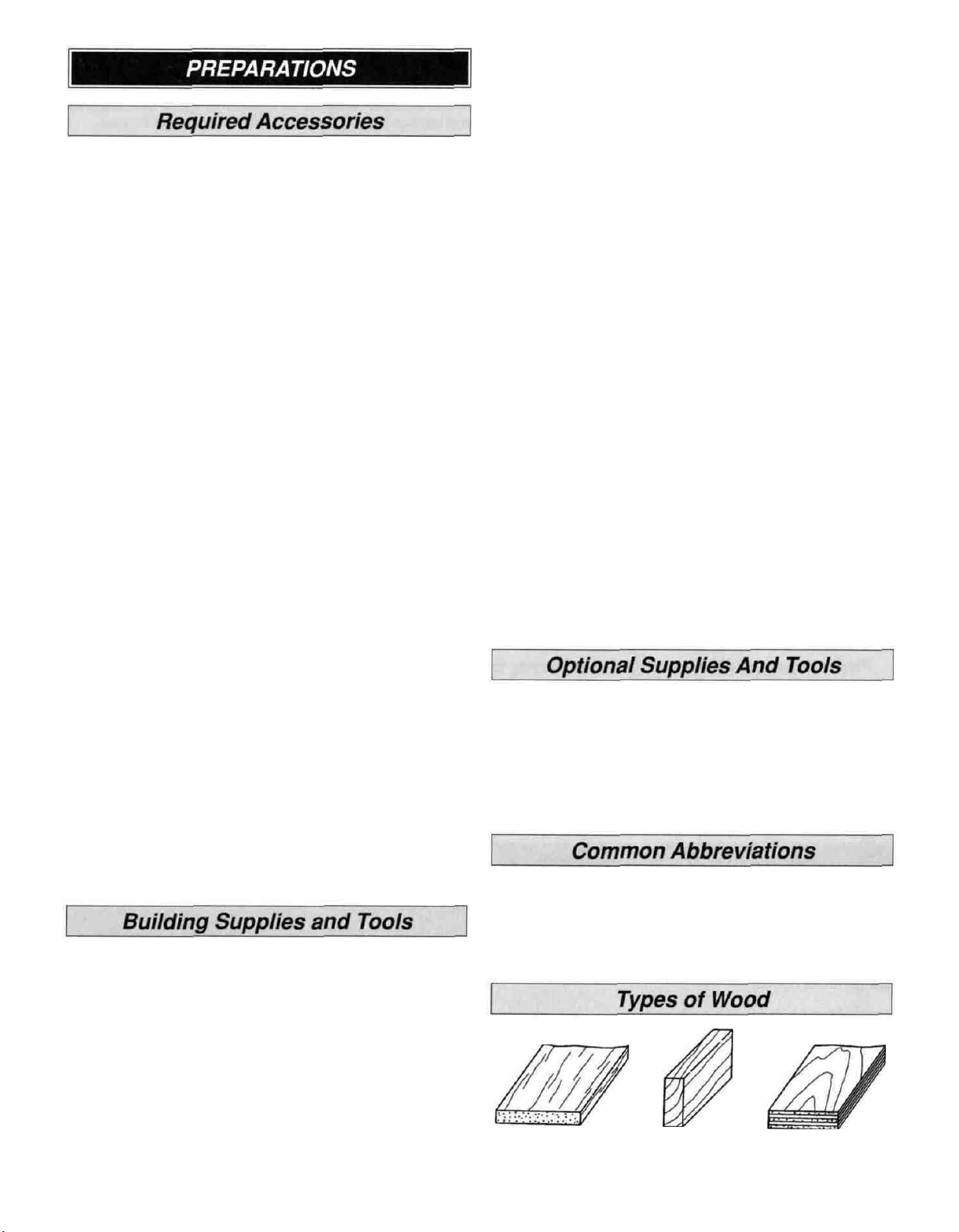
Balsa Basswood Plywood
4
Page 5
In our busy workshop we use the Great Planes
Easy-Touch Bar Sanders equipped with Great Planes
#80, #150 and #220-grit Easy-Touch Adhesive-Backed
Sandpaper Great Planes Easy-Touch Bar Sanders are
made from lightweight, rigid, extruded aluminum and can
be found at most hobby shops They are available in five
sizes - 5-1/2" (GPMR6169), 11" (GPMR6170) for most
general purpose sanding, 22" (GPMR6172), 33"
(GPMR6174) and 44" (GPMR6176) for long surfaces such
as wing leading edges. The Easy-Touch Adhesive-Backed
Sandpaper comes in 2" x 12' rolls of 80-grit (GPMR6180),
150-grit (GPMR6183) and 220-grit (GPMR6185) and an
assortment to 5-1/2" long strips (GPMR6189) for the short
bar sander. The adhesive-backed sandpaper is easy to
apply and remove from your sanding bar when it's time
for replacement.
This setup is all that is required for almost any sanding
task. Custom sanding blocks can be made from balsa or
hardwood blocks and sticks for sanding difficult to reach
spots. We also keep some #320-grit wet-or-dry sandpaper
for finish sanding just before covering.
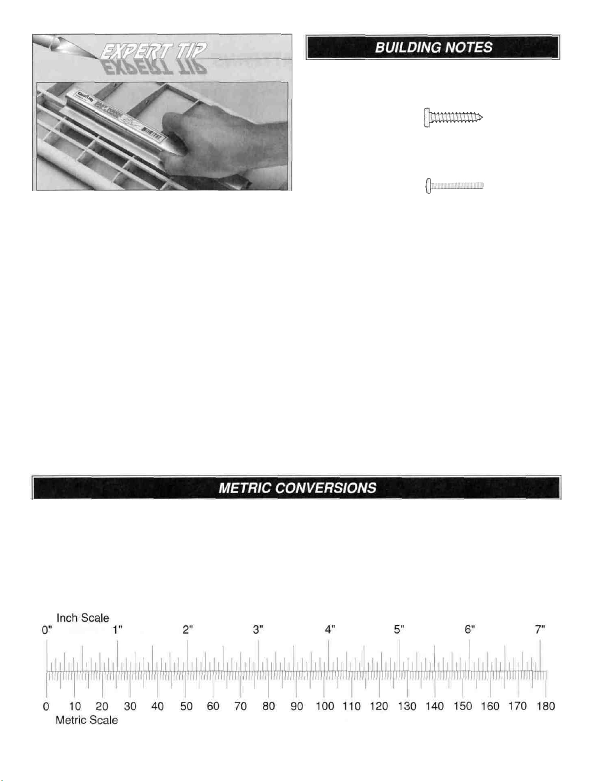
There are two types of screws used in this kit
Sheet metal screws are designated by a number and
a length.
For example #6 x 3/4"
Machine screws are designated by a number, threads per
inch and a length.
For example 4-40 x 3/4"
When you see the term "test fit" in the instructions, it
means you should first position the part on the assembly
without using any glue, then slightly modify the part as
necessary for the best fit.
Whenever Just "epoxy" is specified you may use either
30-minute epoxy or 6-minute epoxy When 30-minute
epoxy is specified it is highly recommended that you use
only 30-minute (or slower) epoxy because you will need
either the working time and/or the additional strength.
Several times during construction we refer to the "top" or
'bottom" of the model or a part of the model For example,
during wing construction we tell you to "glue the top main
spar" or "trim the bottom of the former ' It is understood that
the "top" or "bottom" of the model is as it would be when the
airplane is right side up and will be refered to as the "top"
even if the model is being worked on upside down. i e the
"top" main spar is always the "top" main spar, even when
the wing is being built upside down.
1/64"
1/32"
1/16"
3/32"
1/8"
5/32"
3/16"
1/4"
=
=
=
=
=
=
=
=
.4mm
.8 mm
1.6
mm
2.4mm
3.2
mm
4.0
mm
4.8 mm
6.4mm
3/8"
1/2"
5/8"
3/4"
1"
2"
3"
6"
=
=
=
=
=
=
=
=
152.4
5
9.5 mm
12.7 mm
15.9
mm
19.0
mm
25.4 mm
50.8 mm
76.2
mm
mm
12"
18"
21"
24"
30"
36"
=
304.8 mm
=
457.2 mm
=
533.4 mm
=
609.6 mm
=
762.0 mm
=
914.4 mm
Page 6
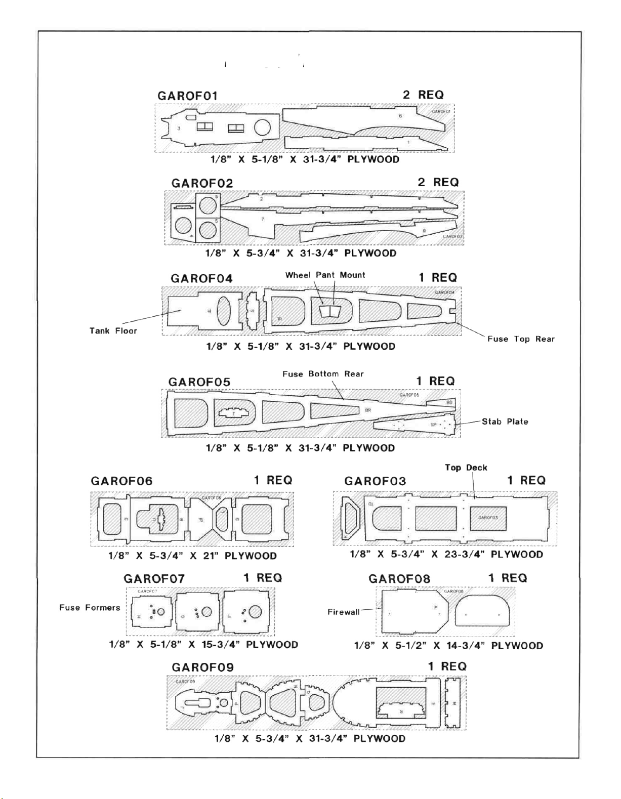
DIE-CUT PATTERNS
6
Page 7
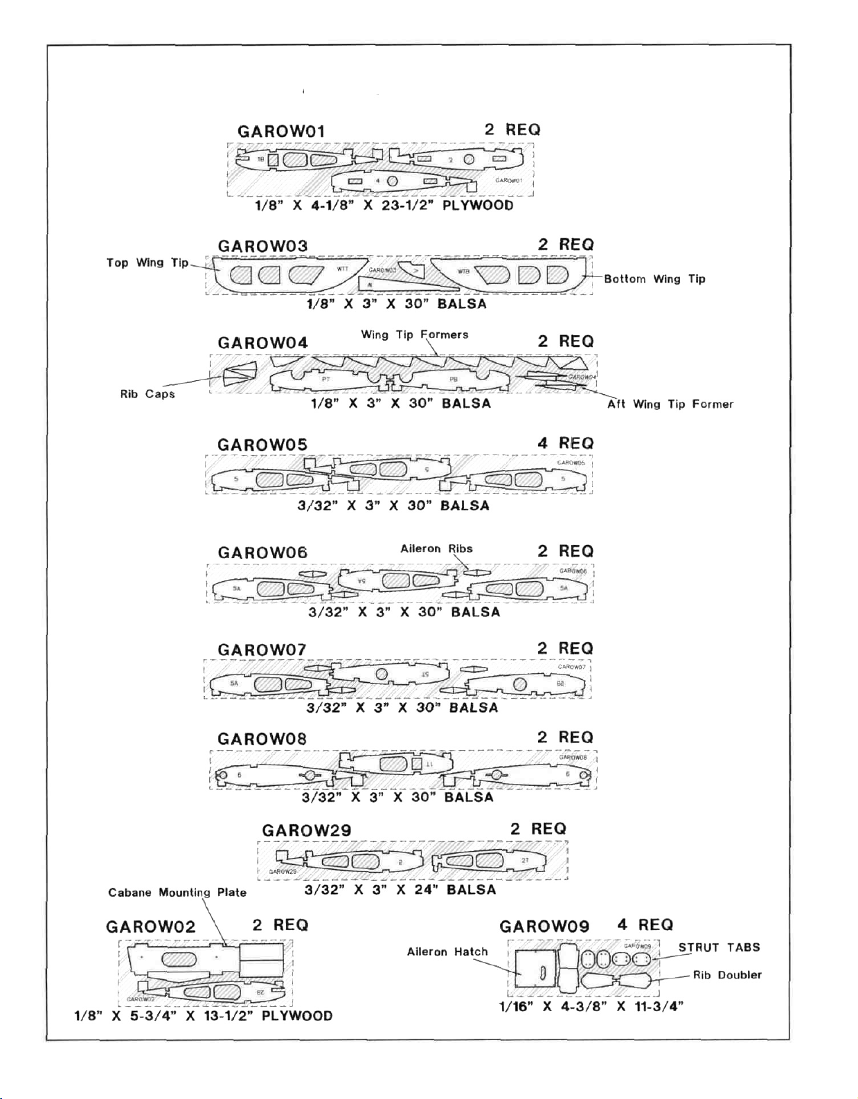
DIE-CUT PATTERNS
7
Page 8
D 1. Unroll the plan sheets. Reroll the plans inside out to
make them lie flat.
D 2. Remove all parts from the box. As you do, determine
the name of each part by comparing it with the plans and
the parts list included with this kit. Using a felt-tip or
ballpoint pen, lightly write the part name or size on each
piece to avoid confusion later. Use the die-cut patterns
shown on pages 6 & 7 to identify the die-cut parts and mark
them before removing them from the sheet. Save all
scraps. If any of the die-cut parts are difficult to remove, do
not force them! Instead, cut around the parts. Use your
Easy-Touch Bar Sander or sanding block to lightly sand the
edges to remove any die-cutting irregularities.
D 3. As you identify and mark the parts, separate them
into groups, such as fuse (fuselage), wing, fin, stab
(stabilizer) and hardware. Zipper-top food storage bags
are handy to store your parts as you sort, identify and
separate them into subassemblies.
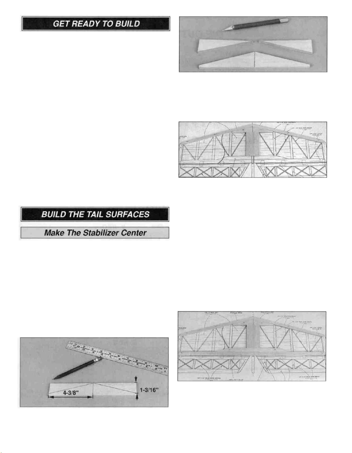
D 1. Begin making the stab LE joiner by accurately
cutting the 3/8" x 1-1/2" x 11-7/8" balsa sheet so it is
8-3/4" long and 1 -3/8" wide.
D 2. Use a ballpoint pen and a model building square to
accurately mark the centerline of the stab LE joiner
(4-3/8" from the end). Use your pen to mark another line
on both ends of the stab LE joiner 1-3/16" from one edge.
The following photo shows the locations of these marks.
D 4. Use a hobby knife with a sharp #11 blade or razor
saw to cut along the lines you drew. If necessary, use a
bar sander to true the leading edges you just cut.
Build The Stabilizer
D 1. Place a piece of wax paper over the stab plan so the
glue won't stick to it. Pin the stab LE joiner in position
over the plan. Glue the 3/8" x 2-3/4" x 5-1/8" balsa stab
center to the stab LE joiner. Cut two 3/8" x 1/2" x 30"
balsa sticks 15-3/4" long to make the stab leading
edges. Sand an angle on one end of both sticks to match
the centerline of the stab. Don't cut the tips of the LE'S
yet. Cut and square them with the end of the stab after
you remove it from the plan at step 5. Glue the stab LE'S
to the stab LE joiner with medium CA and pin them in
position over the plan.
Note: Refrain from using excessive accelerator. Even
hours after it's sprayed on, residual accelerator can
prematurely, and unexpectedly, cure the CA you use
later on nearby glue joints. Unless you must handle or
remove the part from your building board right away,
we recommend using no accelerator at all.
D 3. Use a straightedge to draw a line connecting the
centerline of the stab LE joiner with the marks on
the ends.
D 2. Cut and sand the angle at both ends of the 3/8" x
3/4" x 14-7/8" balsa stab sub TE. Glue the stab sub TE to
the stab center and pin it in position over the plan. Glue
the 3/8" x 3/4" x 30" balsa stab TE to the stab sub TE and
pin it in position over the plan. Use the plans or a
straightedge as a guide to make sure the stab TE is
straight as you glue and pin it in position.
8
Page 9
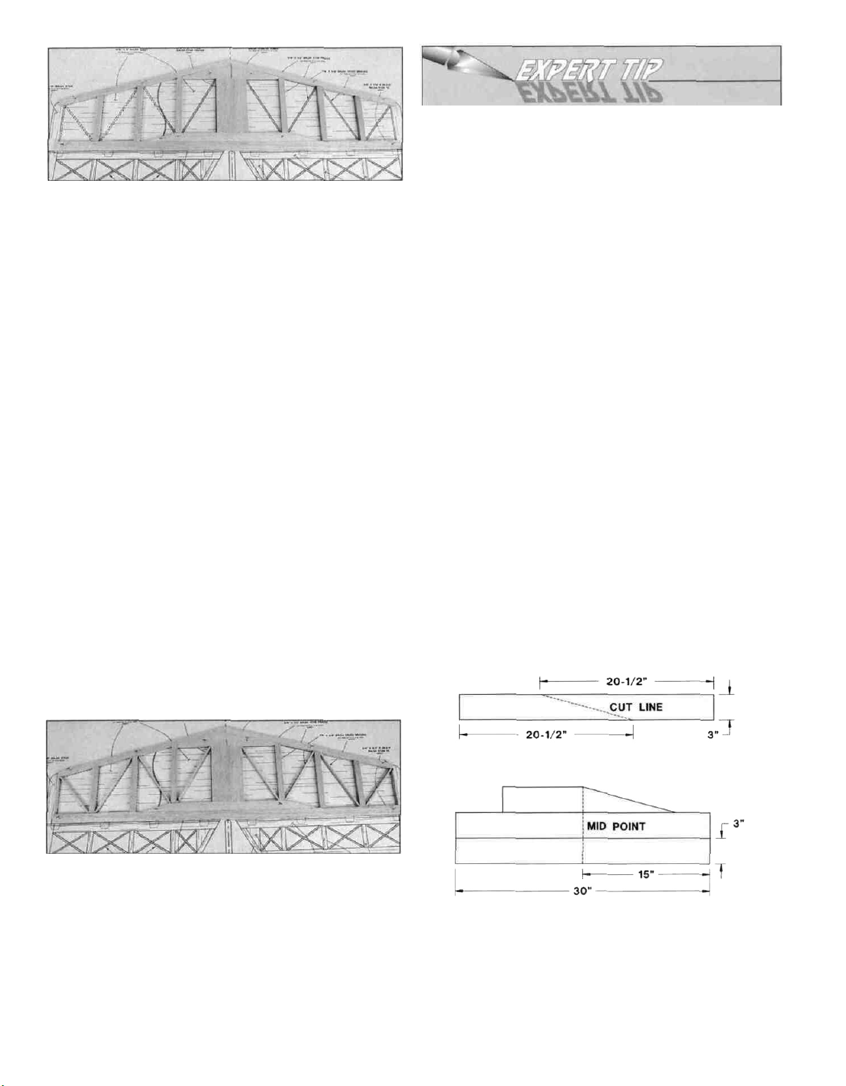
How to Make Stab Skins:
• Wherever practical, prejoin the balsa sheets to make
a "skin" before attaching them to the structure.
D 3. Make the 3/8" stab ribs from a 3/8" x 1/2" x 30"
balsa stick, then glue them in position. Hint: Use a sharp,
single-edge razor blade to cut the stab ribs.
D 4. From a 1/8" x 3/8" x 30" balsa stick, make the 1/8"
cross bracing. Glue them in position between the stab
ribs. We recommend cutting these cross braces with a
single-edge razor blade, too.
• Many modelers like to sort the wood so they can put
the best wood with the most even grain structure on
the top of the stab.
• Make your skin larger than needed to allow for
misalignment. On the stab we suggest leaving 1/4"
extra.
• To make skins, the following steps are suggested:
1. True up the edges of the sheets with a metal
straightedge and a sharp hobby knife or a long
Easy-Touch Bar Sander.
2. Test fit the sheets together to make sure they match well.
3. Method "A": The fastest method for gluing the sheets
together is with thin CA over a flat surface covered with
wax paper. A quick wipe of the joint with a fresh paper
towel will remove most of the excess glue and make
sanding easier. Mark the poorest surface with an "I" as
the inside of the sheet.
Method "B": An alternate method for gluing the pieces
that make up the skin is to glue them together with
aliphatic resin (wood glue). Aliphatic resin sands much
easier than CA so your skins won't get too thin from over
sanding. Wipe off the excess glue with a damp paper
towel. Use masking tape to hold the sheets together
until the glue cures - usually in about thirty minutes.
D 5. Remove the stab from your building board. Inspect
all the glue joints and add CA to any joints that don't look
strong. Cut the ends of the leading and trailing edges so
they extend past the end of the stab about 1/16". Use
your bar sander to finish the job by sanding the ends of
the LE'S and TE so they are flush with the end of the stab.
Use your bar sander or a large sanding block and 220-grit
sandpaper to sand the entire top and bottom surface of
the stab until it is flat and even. Be careful that you don't
sand any area
bracing and ribs by snagging the sandpaper on them.
of
the stab too
thin
or
gouge the stab
cross
D 6. Make the skins for the stab by using five 1/16" x 3" x
30" balsa sheets. Cut one 1/16" x 3" x 30" as shown in the
the top sketch. Make a pair of skins by edge-gluing two
1/16" x 3" x 30" balsa sheets together. Center and glue
the cut sheet on the edge of the glued sheets. Use your
bar sander or a large sanding block and 220-grit
sandpaper to sand the entire top and bottom of the
skin flat.
9
Page 10
D 7. Place one of the stab skins on your building board.
Apply an even bead of medium or thick CA to one side of
the stab framework. Place the framework in its proper
position on the skin and press it down firmly until the glue
has set. Repeat this step for the other side of
the stab.
D 8. After the glue has cured, remove the stab from the
building board and trim the sheeting close to the
framework. Use a bar sander or large sanding block and
220-grit sandpaper to sand the top and bottom skins flush
with the stab framework. Cut the tips from the 1/2" x 7/8"
x 24" balsa stick. Glue the tips onto the end of the stab
and sand a radius on the corner of the LE.
D D 1. Place a piece of wax paper over the elevator plan.
Cut the 1/2" x 7/8" x 24" balsa stick 3-5/8" long to make
an elevator tip. Pin the elevator tip to the plan, allowing
the tip to overhang by 1/16" at the LE and TE.
D D 6. Make the 1/8" cross bracing from a 1/8" x 1/4" x
30" balsa stick. Note that the cross bracing overlaps. The
bottom bracing should be flush with the bottom of the
elevator and the top bracing should be flush with the top
of the elevator. Glue the cross bracing in position. We
recommend cutting these cross braces with a single-edge
razor blade.
D D 7. Remove the elevator from your building board.
Inspect all the glue joints and add CA to any joints that
don't look strong. Cut the end of the leading edge so that
it extends past the end of the elevator about 1/16". Use
your bar sander to finish the job by sanding the ends of
the LE and elevator tip so they are flush. On the end of
the elevator root, sand a radius to match the plan. Sand
the entire top and bottom surface of the elevator until it is
flat and even. Be careful that you do not sand any
particular area of the elevator too thin or gouge the
elevator cross bracing and ribs by snagging them on
the sandpaper.
D 8. Go back to step 1 and build the second elevator
following the same procedure.
D D 2. Cut a 1/2" x 3/4" x 30" balsa stick in half to make
the elevator leading edge and elevator trailing edge. Use
the plan or a straightedge as a guide to make sure the
elevator LE is straight as you glue and pin it in position.
D D 3. Cut and sand the end of the elevator TE to match
the plan. Again, use the plan or a straightedge as a guide
to make sure the elevator TE is straight as you glue and
pin it in position.
D D 4. From the 3/8" x 1/2" x 30" balsa stick, cut and
glue the elevator root to the LE and TE. Leave an
overhang of 1/16" at the TE. This will be sanded off after
the elevator is removed from the building board.
D D 5. Make the 3/8" elevator ribs from the 3/8" x 1/2" x
30" balsa stick. Then glue them in position. From the 1/2"
x 3" x 3-1/2" balsa block, cut the elevator horn block and
glue it in position.
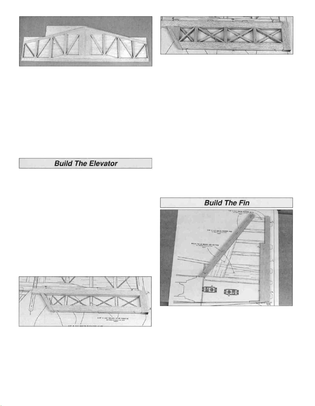
D 1. Place a piece of wax paper over the fin plan. Cut the
3/8" x 3/4" x 24" balsa stick 13-3/4" long to make a fin TE.
Pin the fin TE to the plan, allowing the TE to overhang the
top by 1/16". Cut the remaining 3/8" x 3/4" balsa stick
9-1/8" long to make a fin TE doubler. Glue the fin TE
doubler to the fin TE so that the top end of the TE doubler
is positioned correctly over the plan and the bottom end
overhangs. Cut the second 3/8" x 3/4" x 24" balsa stick to
make the fin LE. Trim one end of the fin LE to the angle
shown on the plan and allow the other end to overhang
the top slightly. Use the plan or a straightedge as a guide
to make sure the fin TE and LE are straight as you pin
them in position.
10
Page 11
D 4. Make the skins for the fin by using three 1/16" x 3" x
30" balsa sheets. Cut each sheet in half. Make a skin by
edge gluing three sheets together. Use your bar sander or
large sanding block and 220-grit sandpaper to sand the
entire top and bottom of the skin flat.
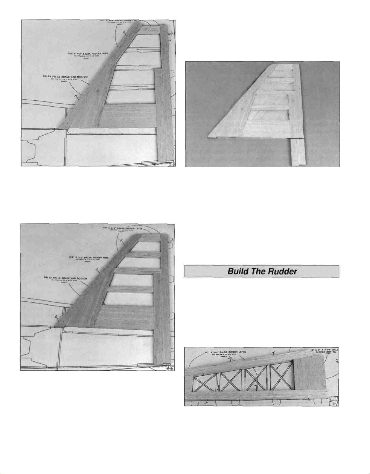
D 2. To make the fin tip, cut the remaining short piece of
3/8" x 3/4" balsa stick to fit between the fin LE and TE.
When satisfied with the fit, glue the fin tip to the LE and
TE. Cut the 3/8" x 3" x 14-7/8" balsa block to make the fin
LE brace and fin bottom. Cut two notches in the fin
bottom for the #8x1" screws that secure the stabilizer to
the fuselage. Glue and pin them in position.
D 5. Pin one of the fin skins down on the building board.
Apply an even bead of medium or thick CA to one side of
the fin framework. Place the framework in its proper
position on the skin so that the LE of the fin is flush with
the edge of the 15" balsa sheet and press it down firmly
until the glue has cured. Repeat this step for the other
side of the fin. Do not apply the 1/16" skin to the fin post.
D 6. After the glue has cured, remove the fin from the
building board. Use your bar sander or a large sanding
block and 220-grit sandpaper to sand the edges of the top
and bottom skins flush with the fin framework.
D 1. Place a piece of wax paper over the rudder plan. Cut
the 1/2" x 3/4" x 30" balsa stick 14" long to make a rudder
LE. Cut the remaining 1/2" x 3/4" balsa stick 12-3/4" long
to make a rudder TE. Pin the rudder LE and TE to the
plan, allowing the ends to overhang the top and bottom of
the rudder by 1/16". Use the plan or a straightedge as a
guide to make sure the rudder TE and LE are straight as
you pin them in position.
D 3. From the 3/8" x 1/2" x 30" balsa stick, make the fin
ribs. Then glue them in position. Remove the fin from
your building board. Inspect all the glue joints and add CA
to any joints that don't look strong. Use your bar sander to
sand the top of the LE and TE so they are flush with the
fin tip. Sand a radius on the end of the LE to match the
plan. Sand the entire top and bottom surface of the fin
until it is flat and even. Be careful that you do not sand
any particular area of the fin too thin or gouge the fin
cross bracing and ribs by snagging them on the
sandpaper.
D 2. Make the rudder tip by cutting the remaining short
piece of 1/2" x 7/8" balsa stick to fit between the rudder
LE and TE. When satisfied with the fit, glue the rudder tip
to the LE and TE. Cut the 1/2" x 3" x 3-1/2" balsa block to
make the rudder bottom. Glue and pin the rudder bottom
in position.
11
Page 12
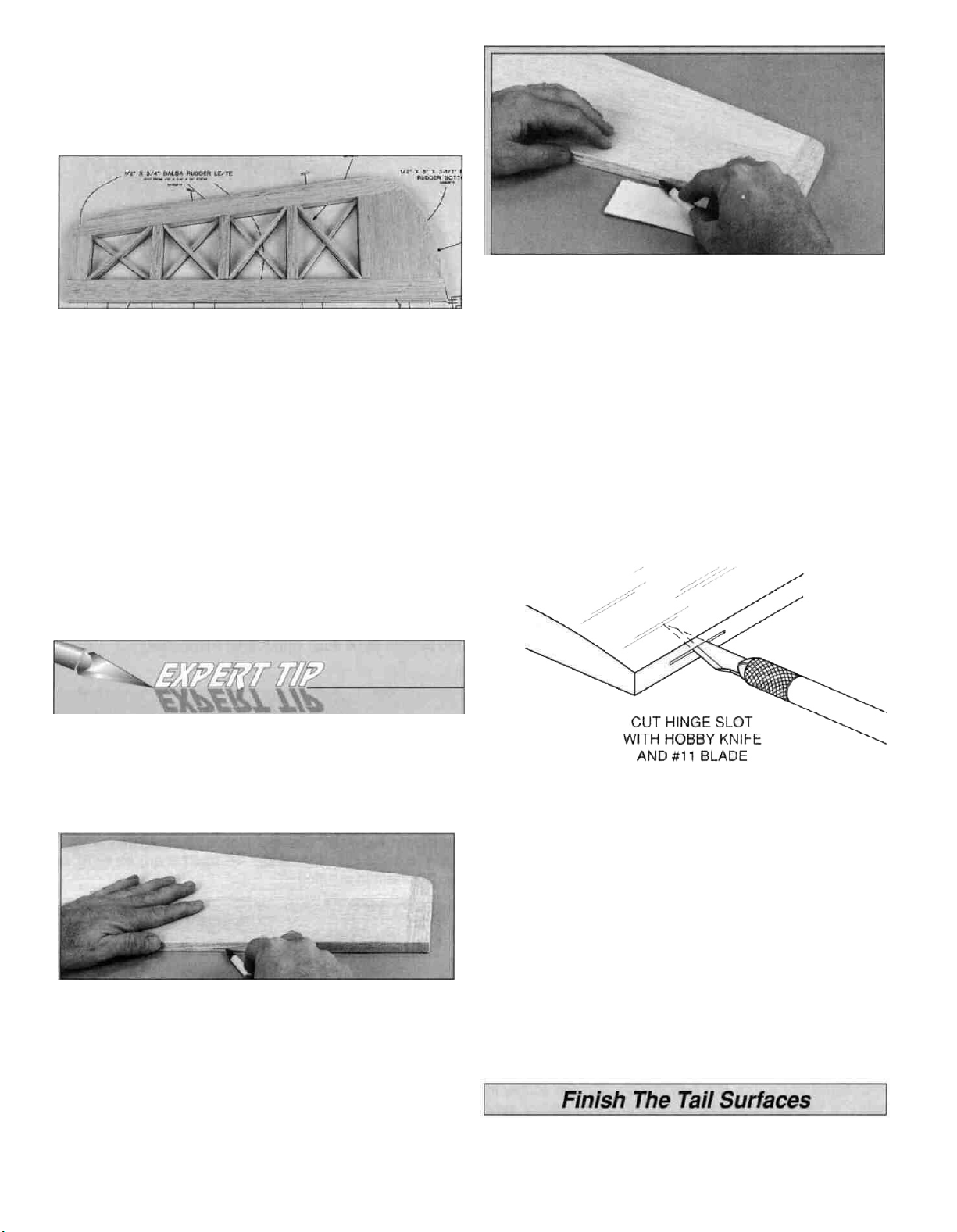
D 3. Make the rudder ribs from the 3/8" x 1/2" x 30"
balsa stick, then glue them in position. Make the 1/8"
cross bracing from a 1/8" x 1/4" x 30" balsa stick. Note
that the cross bracing overlaps the same as on the
elevator. Glue the cross bracing in position.
D 4. Remove the rudder from your building board. Inspect
all the glue joints and add CA to any joints that don't look
strong. Use your bar sander to sand the ends of the LE
and TE so they are flush with the rudder tip and rudder
bottom. Sand a radius on the TE and rudder bottom to
match the plan. Sand the entire top and bottom surface of
the rudder until it is flat and even.
Hinge The Tail Surfaces
C. Use playing cards or business cards to adjust the
height of the pen until you can mark the centerline. Mark
the hinge centerline at each hinge location.
D. Use the same technique to mark the centerline along
the entire length of both elevators.
D 1. Place the stab and elevator over their locations on
the plan and lightly mark the hinge locations on the TE
of the stab and LE of the elevator with a ballpoint pen.
D 2. Refer to the Expert Tip that follows. Then mark the
centerline of the hinges on the stab and elevators.
How to mark hinge slots
It's important that the hinges are centered and parallel
to the part you are hinging. The best way to start is by
accurately marking the hinge centerline. We'll start with
the stabilizer.
D 3. If using a flat type hinge, cut the hinge slots in the
elevator and stab using a #11 blade. Begin by carefully
cutting a shallow slit at the location to accurately establish
the hinge slot. Make three or four more cuts, going a little
deeper each time. As you cut, slide the knife from side to
side until the slot has reached the proper depth and width
for the hinge.
A. Lay the stabilizer and a ballpoint pen on a flat
surface. Mark a "test line" on the trailing edge of the
stab away from the hinge locations you marked earlier.
B. Flip the stab over and mark another line in the same
location as the first. If you see only one line, then it is on
center. Proceed and mark the hinge centerline at each
hinge location. If you see two lines you will have to
adjust the height of the pen until you can mark
the centerline.
D 4. Follow the same procedures to hinge the rudder and fin.
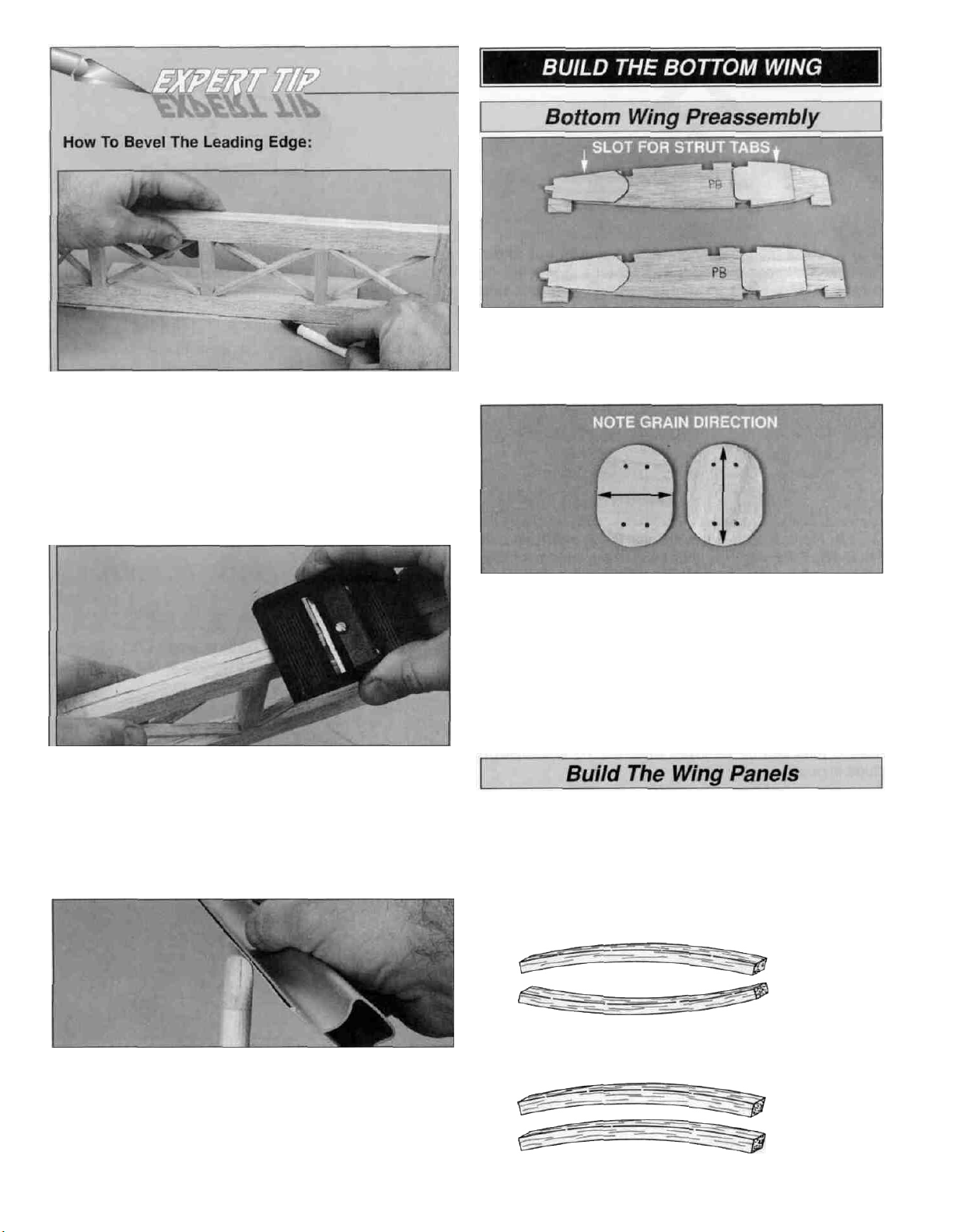
D 1. Refer to the Expert Tip that follows and shape the
leading edge of the elevators to a "V" as shown on the plans.
12
Page 13
A. Place the leading edge of one of the elevators on
your work surface and use your ballpoint pen to mark a
"bevel to" line on both sides about 3/16" high.
Note: You will probably have to adjust the height of the
elevator with card stock (as you did while marking the
hinge slots) so your "bevel to" line is not too high making too sharp of a "V".
D. Using the bevel to lines and the centerline as a guide,
make the "V" on the leading edge of the elevators with a
razor plane or your bar sander loaded with 150-grit
sandpaper.
D 2. Use the same procedure to bevel the leading edge
of the rudder.
D 1. Use 30-minute epoxy to glue the four forward and
four aft die-cut 1/16" ply rib doublers to both sides of the
two die-cut 1/8" balsa R-PB ribs. Take extra care to not
get epoxy in the slots for the strut tabs.
D 2. Use 30-minute epoxy to glue the sixteen die-cut
1/16" ply strut tabs together to make eight pairs. Note:
The die-cut 1/16" ply strut tabs have been cut with the
wood grain running in opposite directions. Glue together
one of each to make 1/8" plywood strut tabs. Also make
sure that the punch marks can be seen.
D 3. After the epoxy has cured, drill a 1/16" hole through
the strut tabs, at each of the punch marks.
Start by building the bottom right wing panel right side up
over the right wing panel plan. Match together sets of
spars so any warps will counteract each other.
D 3. Draw a centerline on the stab LE, stab tips, elevator
tips, elevator TE'S, fin LE, fin tip, rudder tip and rudder TE.
Use you bar sander and 150-grit sandpaper to round the
edges as shown on the plan. Use the centerline as a
guide to keep the radius symmetrical. Do not round the
TE of the stab.
TWO WARPED SPARS INSTALLED
THIS WAY WILL RESULT IN A
STRAIGHT WING
RIGHT
TWO WARPED SPARS INSTALLED
THIS WAY WILL RESULT IN A
WARPED WING
WRONG
13
Page 14
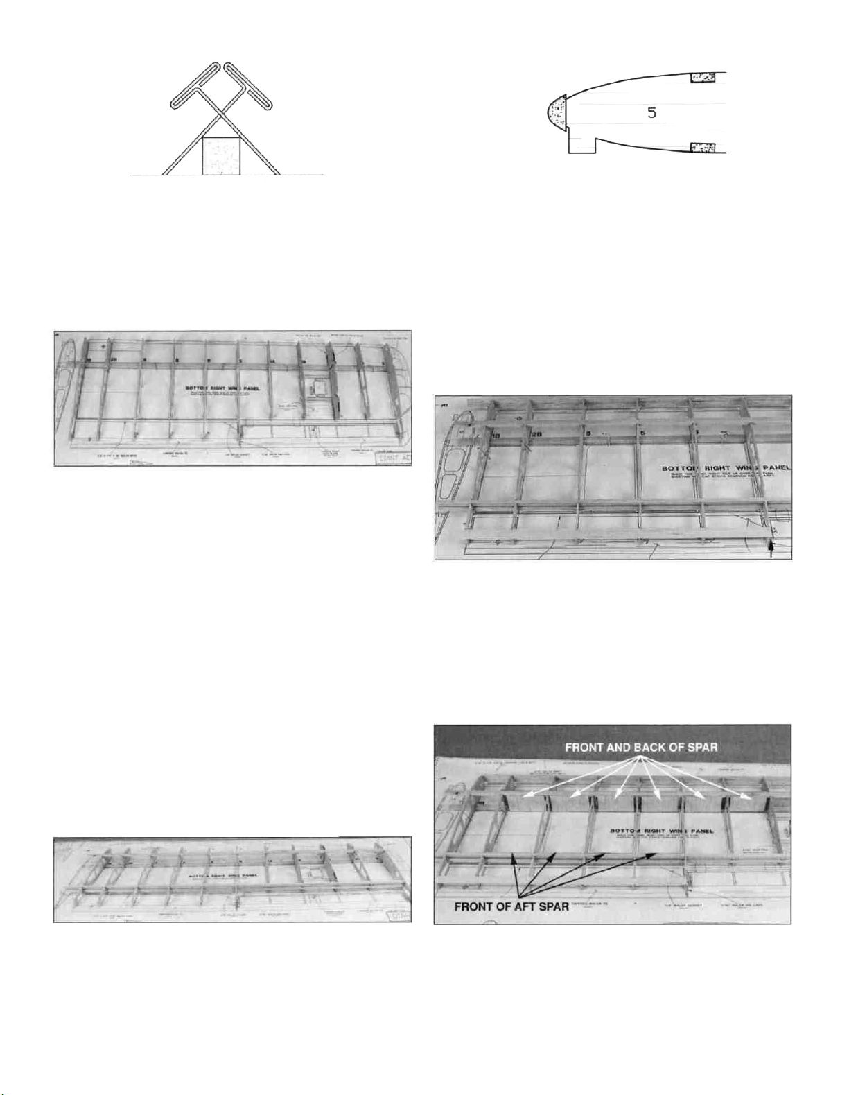
D D 1. Cover the bottom right wing plan with wax paper.
Then use the cross-pinning technique (see sketch above)
to pin a 3/16" x 1/2" x 36" hardwood main bottom spar
over the wing plan. The spar should be flush with the
outside face of rib R-6.
D D 2. Place the die-cut wing ribs R-1B, R-2B, R-5, R-
5A, R-5B, R-PB and R-6 on the top of the spar, over their
locations on the plan.
D D 5. Position the 36" shaped balsa leading edge (LE)
on the front of the ribs. The LE should be centered on all
ribs and the tip end should extend past rib R-6 by at least
1-5/8". Make sure all the jig tabs are contacting the
building board, then use thin CA to glue the LE to the front
of the ribs.
Note: While the jig tabs should be contacting the plan,
you should check rib alignment with a straightedge. Shim
the forward or aft jig tabs with paper to raise any ribs that
are low. Use small T-pins to pin the forward and aft jig
tabs to the building board over their location on the plan.
On the aft jig tabs, insert the T-pins at an angle from the
rear so they can be removed after the TE and sheet is
glued in position.
D D 3. Place the 3/16" x 1/2" x 36" hardwood main top
spar in the notches of the ribs. The end of the spar should
be flush with the outside face of rib R-6 and with the top of
the ribs. With the ribs perpendicular to the building board,
glue the ribs to the top and bottom spars with thin CA.
D D 4. Insert the 1/4" x 1/4" x 36" balsa aft spars in the
notches in the aft end of the ribs. The end of the spar
should be flush with the outside face of rib R-6 and with
the edges of the ribs. As you are gluing the spars to the
ribs with thin CA, check that the ribs are perpendicular
to the building board and the jig tabs are against the
building board. (See note above.)
D D 6. Cut the 36" balsa trailing edge (TE) 17" long.
Use thin CA, to glue the TE to the ends of ribs R-1B, R-2B
and R-5.
D D 7. From the 3/32" x 3" x 24" balsa sheets, make
shear webs to fit on the front of the main spar starting at
rib R-2B to R-6, behind the main spar from rib R-2B to
R-5B and to the front of the aft spar from rib R-2B to the
aileron bay. The grain of the shear webs runs
perpendicular to the spars and the shear webs must be
glued securely to the spars.
14
Page 15
D D 8 Use medium CA to glue the die-cut 1/8" balsa
gusset to rib R-5 and the shear web Sand the TE flush
with rib R-5 Then glue the die-cut 1/8" balsa rib caps to
ribs R-5 and R-6.
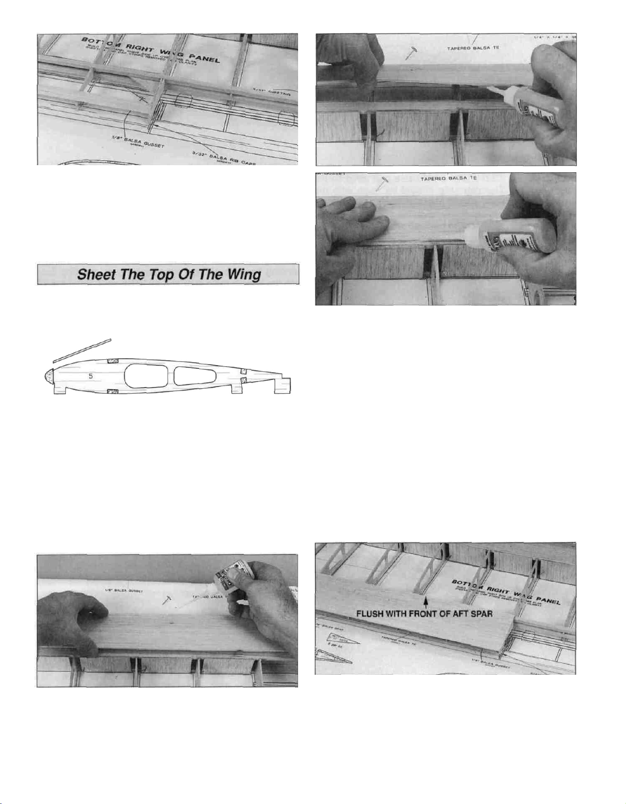
D D 1 Fit a 3/32" x 3" x 36" balsa sheet to the top of the
wing panel by first sanding a bevel on the front edge of
the sheet to match the angle of the leading edge of the
wing Before you glue the LE sheet in position, remove
the T-pins from the front jig tabs Reinstall the T-pins
through the ribs right behind the bottom main spar
D D 3 Wet the sheet once more Carefully lift the sheet
away from the ribs Then apply a bead of medium or thick
CA to the top of each rib Working quickly, pull the sheet
back toward the main spar as you press it down to the
ribs and spar Glue the aft edge of the sheeting to the
main spar with thin CA Use masking tape T-pins or
weights to hold the sheet to the ribs until the CA cures
Note: Save all leftover 3/32" sheeting for use on the
fuselage.
D D 2 Wet the outside of the LE sheet so it will bend
more easily Hint: A 50/50 mix of water and either alcohol
or ammonia helps soften the wood fibers so the sheet is
even easier to bend Position the front of the sheet
against the LE and flush with the side of rib R-6 Glue it in
position with thin CA.
D D 4 Lightly sand the TE area so that the TE and aft
balsa spar are flush with the top of the ribs From a 3/32"
x 3" x 36" balsa sheet, cut a TE sheet 17-1/4" long Save
the cut off piece for the bottom TE Glue the sheet to the
TE and ribs so that it overhangs the balsa rib cap, at rib
R-5, by 1/32" and is flush with the front edge of the aft
balsa spar Do not trim the sheet at the TE.
15
Page 16
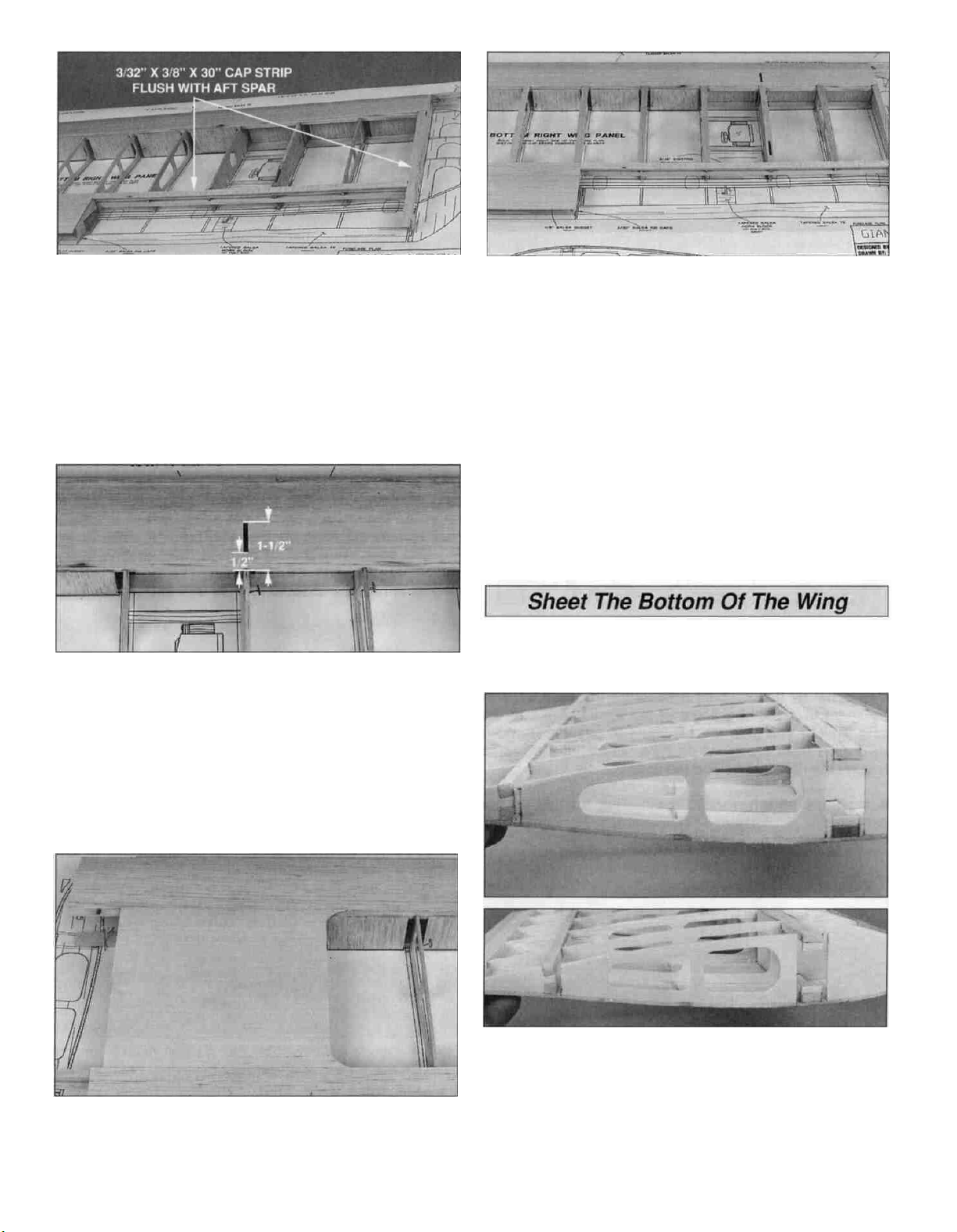
D D 5. Glue a 3/32" x 3/8" x 30" balsa cap strip on the
top of rib R-6. The cap strip should be flush with the
outside of the rib and extend past the TE by 1/2". Use the
leftover cap strip to cover the aft balsa spar from rib R-5
to R-6. The cap strip should be flush with the front of the
aft balsa spar.
D D 6. To locate the slot for the strut tab in rib R-PB,
place a mark 1/2" and 1-1/2" from the aft edge of the top
main spar. Use the side of rib R-PB as a guide to mark
the sides of the slot. Using a sharp hobby knife, trim the
LE sheet from over the slot.
D D 8. From the 3/32" x 3/8" x 30" balsa sticks, cut cap
strips. Use medium CA to glue them to the tops of the
ribs. Be sure to cut an opening for the strut slot in the cap
strip on rib R-PB.
D D 9. Remove the T-pins and take the wing off your
building board. Carefully remove the jig tabs. Using a
sanding bar with 150-grit sandpaper, sand the ribs flush
with the bottom main spar and aft balsa spar. Sand the TE
sheet aft of the TE to match the angle of the TE and ribs.
D D 1. Use a razor saw and sanding bar to accurately cut
the spars, LE, TE and top sheet flush with rib R-1B.
D D 7. Use a 3/32" x 3" x 30" balsa sheet to make the
center sheeting between the LE sheet and the TE sheet.
Before you glue the center sheeting in position, remove
the T-pins from ribs R-1B, R-2B and R-5.
D D 2. On rib R-1B use a straightedge to draw lines
connecting the front of the aft balsa spars, and the corner
of the notch in front of the aft balsa spar. Also, draw lines
connecting the front and aft corners of the top and bottom
main spars. Then draw lines continuing the sides of the
die-cut rectangle. Use a razor saw to cut slots
in front of the aft balsa spar and in front and behind the
main spar.
16
Page 17

D D 3. Use 6-minute epoxy to glue the 1/4" x 3/8" x
3-3/4" hardwood hatch blocks into the notches in ribs R5B and R-PB. After the epoxy has cured, cut hatch
guides from 1/4" x 1/4" x 30" balsa stick. The guides fit
between the hatch blocks and are flush with the top of rib
R-5B and R-PB. Glue in place with thin CA.
D D 4. Fit a 3/32" x 3" x 36" balsa sheet to the bottom of
the wing panel by first sanding a bevel on the front edge
of the sheet so it matches the leading edge of the wing.
Install the bottom LE sheet following the same procedure
used to install the top LE sheet.
D D 5. From the 3/32" x 3" x 36" balsa sheet leftover
from the top TE, sheet the bottom TE from rib R-1B to R-5
following the same procedure.
D D 6. Glue a 3/32" x 3/8" x 30" balsa cap strip on the
bottom of rib R-6. The cap strip should be flush with the
outside of the rib. Use the left over cap strip to sheet the
aft balsa spar from rib R-5 to R-6. The cap strip should be
flush with the front of the aft balsa spar.
D D 7. Use a 3/32" x 3" x 30" balsa sheet to sheet the
center of the wing panel between the LE and TE sheets.
There may be a slight gap between the sheets. Use thick
CA to fill the gap, wipe off the excess then spray the area
with accelerator to harden the joint.
D D 9. Use medium CA to glue 3/32" balsa cap strips to
the ribs at the side of the aileron servo hatch. From a
3/32" x 3" x 24" balsa sheet, fill the gap between the hatch
and the LE sheet and the hatch and the TE sheet. Leave
a 1/32" gap around the hatch to allow for the thickness of
the covering. Save the leftover sheet for use around the
hatch on the other wing panels.
D D 10. From the 3/32" x 3/8" x 30" balsa sticks, cut cap
strips for the remaining ribs. Use medium CA to glue them
to the bottom of the ribs.
D D 1. Use a razor saw and sanding bar with 150-grit
sandpaper to trim the bottom sheeting flush with rib R-1B.
Also, sand the sheeting in the aileron bay flush with the
aft balsa spars and the balsa rib caps.
D D 8. Center the die-cut 1/16" birch ply aileron servo
hatch over the opening for the aileron servo. Tape the
hatch in place and drill six 1/16" pilot holes at the punch
marks on the aileron hatch and into the hatch blocks.
Remove the hatch and place a drop of thin CA in each
hole in the hatch block. Wipe off the excess CA. Enlarge
the holes to 1/8". Reinstall the hatch. Secure the hatch
to the hatch blocks with six #2 x 3/8" flat head
screws (SCRW024).
D D 2. From the 5/16" x 15/16" x 18" balsa stick make a
sub TE to fit between the rib caps, against the aft balsa
spars. Glue the sub TE centered on the aft balsa spars
and rib caps. Use a sanding bar to sand the edges of the
sub TE flush the the wing sheeting.
D D 3. Use medium CA to glue the die-cut 1/8" balsa
wing tip perpendicular to rib R-6. Glue the die-cut 1/8"
balsa wing tip formers to the top and bottom of the wing
tip. Sand the tip of the formers flush with rib R-6.
17
Page 18

How To Make Servo Lead Tubes:
When the aileron servos are mounted out in the wing, it
can be difficult to run the servo wires through the ribs to
the wing root. An easy solution is to make servo
wire tubes.
A. Cut a piece of newspaper slightly longer than the
length needed to reach from the aileron servo bay to the
wing root.
B. Roll the newspaper into a tube slightly smaller than
the holes in the wing ribs. Use a couple of pieces of tape
to hold the tube together.
D 2. After you are satisfied with the fit, take the wing
joiners and bolt plate out of the wing panels. Mix
approximately 1 oz. of 30-minute epoxy. Use plenty of
epoxy to coat the main and aft spars, the slot in ribs
R-1B and R-2B, the wing joiners, bolt plate and the face
of ribs R-1B. Insert the wing joiners and bolt plate in the
wing panel and press the wing panels together. Wipe off
any excess epoxy with rubbing alcohol and a paper towel.
Tape the two wing panels together and weight them down
on a flat surface. Check that the LE is straight and the
wing panels are flat against the surface.
C. Insert the tube into the wing aligning the holes with
the tube. Tack glue the tube to the ribs with CA.
D 4. Give the wing panel a quick sanding. Then set it
aside while you go back and build the left wing panel.
D 1. Sand the spars, LE, TE and sheeting flush with rib
R-1B. Without using any glue, test join the wing panels
by inserting the 1/8" x 1-5/8" x 5" plywood forward wing
joiners, the 1/8" x 5/8" x 5" plywood aft wing joiner and
the 1/4" x 1" x 12" plywood wing bolt plate into the right
wing panel. Join the left wing panel to the right wing
panel. Set the wing on a flat surface and use a straightedge to check that the LE is straight. If not, use a sanding
bar to sand the wing root and test fit again.
D 3. Use a sanding bar to sand the bottom center section
smooth and the TE straight. Draw a centerline on the top
of the die-cut 1/8" plywood wing plate. Also, draw a line
1/4" from the aft edge. Sand a taper on the edges of the
wing plate. Use 6-minute epoxy to glue the wing plate,
centered on the TE of the wing. Note: The wing plate
overhangs the TE by 1/4" as shown on the wing plan.
After the epoxy cures, balsa filler can be applied to make
a smooth transition from the wing plate to
the wing.
D D 1. Lay a piece of wax paper over the right aileron
plan. Cut a 3/32" x 3" x 36" balsa sheet in half. Trim both
sheets to 2-1/8" wide to make the top and bottom
aileron sheeting. Pin one of the sheets in position over
the plan.
18
Page 19

D D 2. Draw lines on the sheet using the alignment
marks on the plan as a guide Align the die-cut 3/32" balsa
aileron ribs with the marks on the sheet Use thin CA to
glue the aileron ribs perpendicular to the bottom sheet
and flush with the LE.
D D 3 Use the leftover balsa TE from the wing panel to
make the TE on the aileron Glue it in position against the
aft end of the aileron ribs with medium CA Remove the
aileron from the building board and using a sanding bar,
sand an angle on the bottom sheet to match the angle of
the ribs and TE
D D 5 As described in the Building The Stabilizer
section, draw a centerline on the aileron LE Then draw a
line 1/4" back on both sides of the aileron LE Mark the
hinge locations and cut the slots for the hinges Using a
razor plane and a sanding bar, bevel the LE as shown on
the wing plans.
D U 6 Draw a centerline on the sub TE of each aileron
bay on the wing Mark the hinge locations and cut the
slots for the hinges Test fit the ailerons to the wing.
It's time to clean off your building table and take a break
before starting the top wing
D D 4 Cut the 4" tapered balsa horn block into four 1"
long pieces Use medium CA to glue the tapered balsa
horn block in position Then use medium CA to glue the
3/32" balsa top sheet to the TE , bottom sheet and flush to
the LE of the ribs Use a sanding bar to sand the LE
smooth Mark the balsa horn block location on the aileron
sheeting with a piece of masking tape Glue a 5/16" x
15/16" x 18" balsa stick to the front of the sheeting and
the aileron ribs to make the aileron LE Sand the LE to
the same angle as the sheeting Sand the sheeting and
LE flush with the end ribs.
D 1 Use 30-minute epoxy to glue the four forward and
four aft die-cut 1/16" ply rib doublers to both sides of the
two die-cut 1/8" balsa R-PT ribs Take extra care not to
get epoxy in the slots for the strut tabs.
D 2 Drill a 1/8" hole through each of the punch marks on
the die-cut 1/8" plywood cabane mounting plates.
D 3 Use 6-minute epoxy to glue the 1/4" x 1" x 2-3/8"
plywood cabane mounting plate doublers to the cabane
19
Page 20

mounting plates. Note: The mounting plates are angled at
one end. Be sure to to make a left and a right cabane
mounting plate assembly.
D 4. Drill a #10 (13/64") hole through each of the cabane
mounting plate assemblies using the previously drilled
1/8" hole as a guide.
Start by building the right top wing panel, upside down,
over the left wing panel plan.
D D 1. Use the cross-pinning technique to pin a 3/16" x
1/2" x 36" hardwood main spar over the wing plan. The
spar should be flush with the outside face of rib R-6.
Mark and cut the main spar at the splice as shown on the
plan. From a second 3/16" x 1/2" x 36" hardwood main
spar, cut the 3/16" x 1/2" x 7" hardwood main center
spar. Save the excess for the other main spars. Glue the
two spars together with 6-minute epoxy. After the epoxy
has cured, remove the spar and splice the second spar
together over the plan. Don't forget to cover the plans
with wax paper.
with thin CA. Glue the cabane mounting plate assembly to
ribs R-3 and R-4 with medium CA. After the CA has cured,
apply thick CA to make a fillet for added strength.
D D 4. Insert the 1/4" x 1/4" x 36" balsa aft spars in the
notches in the aft slot in the ribs. The end of the spar
should be flush with the outside face of rib R-6 and with
the edges of the ribs. As you're gluing the spars to the ribs
with thin CA. check that the building tabs are touching and
perpendicular to the building board.
D D 5. From the 1/8" x 3/4" x 8" balsa stick, make a sub
LE to fit between ribs R-1T and R-4. Center the sub LE
on the front of the ribs and glue with thin CA. Use a
sanding bar with 220-grit sandpaper to sand the top of the
sub LE flush with the ribs. Use a sanding bar to sand an
angle on the sub LE at rib R-4 for the LE to attach to.
D D 2. Fit the cabane mounting plate assembly into the
slots in ribs R-3 and R-4. Place the die-cut wing ribs R-1T,
R-2T,
R-3,
R-4,
R-5,
R-5A,
R-5T, R-PT and R-6 on the top
of the spar, over their locations on the plan.
Note: The jig tabs should be contacting the plan. Use
small T-pins to pin the forward and aft jig tabs to the
building board over their location on the plan. On the aft
jig tabs, insert the T-pins at an angle from the rear so they
can be removed after the TE and sheeting are glued
in position.
D D 3. Place the second 3/16" x 1/2" x 36" hardwood
main spar in the notches of the ribs. The end of the spar
should be flush with the outside face of rib R-6 and with
the top of the ribs. With the ribs perpendicular to the
building board, glue the ribs to the top and bottom spars
D D 6. Position the 30" shaped balsa leading edge (LE)
on the front of the ribs. The LE should be centered on ribs
R-4 through R-6 and the tip end should extend past rib
R-6 by at least 1-5/8". Make sure all the jig tabs are
contacting the building board. Then use thin CA to glue
the LE to the front of the ribs.
D D 7. Cut the 36" balsa trailing edge (TE) 12" long. Use
thin CA to glue the TE to the ends of ribs R-4 and R-5 so
that 1/16" extends past rib R-5 into the aileron bay. Use a
sanding bar to sand the end of the TE flush with rib R-5.
Sand the other end of the TE at the angle shown on
the plan.
20
Page 21

D D 8. From the 1/8" x 3/4" x 8" balsa stick, make a sub
TE to fit between ribs R-1T and the just installed in step 7.
Center the sub TE on the aft end of the ribs and the balsa
TE and glue with thin CA. Use a sanding bar with 220-grit
sandpaper to sand the top of the sub TE flush with the
ribs and the TE.
D D 2. Lightly sand the TE area so that the TE and aft
balsa spar are flush with the top of the ribs. From a
3/32" x 3" x 36" balsa sheet, cut a TE sheet in half. Save
the other half for the top TE. Glue the sheet to the TE and
ribs so that the forward edge is flush with the forward
edge of the aft balsa spar. The sheet overhangs the balsa
rib cap, at rib R-5, by 1/32". Do not trim the sheet at the
TE. Using a hobby knife and a sanding bar, trim the sheet
flush with the balsa rib cap at R-5.
D D 3. Glue a 3/32" x 3/8" x 30" balsa cap strip on the
top of rib R-6. The cap strip should be flush with the
outside of the rib and extend past the TE by 1/2". Use the
leftover cap strip to sheet the aft balsa spar from rib R-5
to R-6. The cap strip should be flush with the front of the
aft balsa spar.
D D 9. From the 3/32" x 3" x 24" balsa sheets, make
shear webs to fit on the front and back of the main spar
between ribs R-2T and R-3 and from ribs R-4 to R-5T.
The front shear webs extend to rib R-6. Also, glue shear
webs to the front of the aft balsa spars from ribs R-1T to
R-5. The grain of the shear webs runs perpendicular to
the spars and must be securely glued to the spars.
D D 10. Use medium CA to glue the die-cut 1/8" balsa
gusset to rib R-5 and the shear web. Sand the TE flush
with rib R-5. Then glue the die-cut 3/32" balsa rib caps to
ribs R-5 and R-6.
D D 1. Fit a 3/32" x 3" x 36" balsa sheet to the bottom of
the wing panel by first sanding a bevel on the front edge
of the sheet so it matches the leading edge of the wing.
Before you glue the LE sheet in position, remove the
T-pins from the front jig tabs in the wing ribs. Reinstall the
T-pins through the ribs right behind the main spar.
Position the front of the sheet against the LE and flush
with the side of rib R-6. Glue it in position with thin CA.
Wet the sheet so it will bend easier. Then, carefully lift the
sheet away from the ribs and apply a bead of medium or
thick CA to the top of each rib. Working quickly, pull the
sheet back toward the main spar as you press it down to
the ribs and spar. Then glue the aft edge of the sheet to
the main spar with thin CA. Use masking tape, T-pins or
weights to hold the sheet to the ribs until the CA cures.
Using a hobby knife and a sanding bar, trim the sheet
flush with the sub LE.
OPTIONAL AILERON SERVOS IN THE TOP WING
On our test models, the Giant Aeromaster flew great
with aileron servos in the lower wing only. But, if you
would prefer to have aileron servos in both wings, the
aileron servo hatch is installed following the same
procedure as the bottom wing.
1. Use 6-minute epoxy to glue the 1/4" x 3/8" x 3-3/4"
hardwood hatch blocks into the notches in ribs R-5T
and R-PT. After the epoxy has cured, cut hatch guides
from 1/4" x 1/4" x 30" balsa stick. The guides fit
between the hatch blocks and are flush with the top of
rib R-5T and R-PT.
2. Center the die-cut 1/16" birch ply aileron servo
hatch over the opening for the aileron. Tape the hatch
in place and drill six 1/16" pilot holes at the embossed
marks on the aileron hatch and into the hatch blocks.
Remove the hatch and place a drop of thin CA in each
hole in the hatch block. Wipe off the excess CA and
after the CA has cured, reinstall the hatch. Secure the
hatch to the wing with six #2 x 3/8" flat head screws.
3. Use medium CA to glue 3/32" balsa cap strips to the
ribs at the side of the aileron servo hatch. Mark the rear
location of the strut slot on the side of rib R-PT. From
the leftover 3/32" x 3" x 36" balsa sheet used on the
lower wing aileron servo hatch, fill the gap between the
hatch and the LE sheet and the hatch and the TE sheet.
Leave a 1/32" gap around the hatch to allow for the
thickness of the covering. Save the leftover sheet for
use around the hatch on the other wing panel.
4. Use the marks you placed on the side of rib R-PT to
locate the rear strut slot. Use a sharp hobby knife to
trim the sheet from over the slot.
D D 4. To locate the slot for the front strut tab in rib R-PT,
place a mark 1/2" and 1-1/2" from the aft edge of the main
spar. Use the side of rib R-PT as a guide to mark the
sides of the slot. Using a sharp hobby knife trim the sheet
from over the slot.
21
Page 22

D D 5. Use a 3/32" x 3" x 24" balsa sheet to make the
center sheeting that fits between the LE sheet and the
TE sheet. Position the sheeting so that it is perpendicular
to the ribs. Before you glue the center sheeting in
position, remove the T-pins from ribs R-1T through R-5.
Note: The grain direction of the center sheeting should be
perpendicular to the ribs as shown.
D D 6. From the 3/32" x 3/8" x 30" balsa sticks cut cap
strips, then use medium CA to glue them to the tops of the
ribs. Be sure to cut an opening for the strut slot in the cap
strip on rib R-PT.
D D 7. Remove the T-pins. Take the wing off your
building board. Carefully remove the jig tabs and use a
sanding bar with 150-grit sandpaper to sand the ribs flush
with the bottom main spar and aft balsa spar. Sand the TE
sheet, aft of the TE and the sub TE, to match the angle of
the ribs.
D D 1. Use a razor saw and sanding bar to accurately cut
the spars, LE, TE and top sheet flush with rib R-1T.
D D 3. Use the holes in the cabane mounting plate as a
guide to drill a #10 (13/64") hole through the bottom
sheeting. To prevent the balsa sheeting from splitting,
place a wood block behind the sheeting while drilling
though it.
D D 4. Tap the holes with a 1/4-20 tap. Add a couple of
drops of thin CA to the holes to harden the threads. Then
retap the holes after the CA has fully cured.
D D 5. Fit a 3/32" x 3" x 36" balsa sheet to the top of the
wing panel by first sanding a bevel on the front edge of
the sheet so it matches the leading edge of the wing.
Also, sand the sub LE flush with the ribs. Install the top LE
sheet following the same procedure used to install the
bottom LE sheet.
D D 2. On rib R-1T use a straightedge to draw a line from
the front edge of the top main spar to the front edge of the
bottom main spar. Draw a line from the back edge of the
top main spar to the back edge of the bottom main spar.
Draw lines continuing the sides of the die-cut rectangle.
Use a razor saw to cut a slot in front and behind the
main spar.
D D 6. From the remaining 3/32" x 3" x 36" balsa sheet
used to sheet the bottom TE, sheet the top TE from rib
R-1T to R-5 following the same procedure.
D D 7. Glue a 3/32" x 3/8" x 30" balsa cap strip on the
top of rib R-6. The cap strip should be flush with the
outside of the rib. Use the leftover cap strip to sheet the
aft balsa spar from rib R-5 to R-6. The cap strip should be
flush with the front of the aft balsa spar.
D D 8. Use a 3/32" x 3" x 24" balsa sheet to make the
center sheeting between the LE and TE sheet on the top
of the wing.
22
Page 23

D D 9. From the 3/32" x 3/8" x 30" balsa sticks, cut cap
strips, and then use medium CA to glue them to the
bottom of the ribs.
D D 1. Use a razor saw and sanding bar with 150-grit
sandpaper to trim the top sheeting flush with rib R-1T and
the sub LE and TE. Also sand the sheeting, in the aileron
bay area, flush with the aft balsa spars and the balsa
rib caps.
D 1. Sand the spars, LE, TE and sheeting flush with rib
R-1T. Sand the wing tip ribs flush with the top and bottom
sheeting. Using a razor saw, cut the 1/8" x 1-5/8" x 5"
plywood forward wing joiners 4-13/16" long. Without
using any glue, test join the wing panels by inserting the
forward wing joiners and the two die-cut 1/8" plywood aft
wing joiners into the right wing panel. Join the left wing
panel to the right wing panel and set the wing on a flat
surface. Use a straightedge along the sub LE to check that
the LE is straight.
D 2. After you are satisfied with the fit, take the wing joiners
out of the wing panels. Mix approximately 1 oz. of 30minute epoxy. Use plenty of epoxy to coat the main and aft
spars, the wing joiners and the face of ribs R-1T. Insert the
wing joiners in the wing panel and press the wing panels
together. Wipe off any excess epoxy with rubbing alcohol
and a paper towel. Tape the two wing panels together and
weight them down on a flat surface. Check that the sub LE
is straight and the wing panels are flat against the surface.
D D 2. From the 5/16" x 15/16" x 18" balsa stick, cut a
sub TE to fit between the rib caps, against the aft balsa
spars in the aileron bay. Glue the sub TE to the aft balsa
spars and use a sanding bar to sand the edges flush with
the wing sheeting.
D D 3. Use medium CA to glue the die-cut 1/8" balsa
wing tip (TTW) perpendicular to rib R-6. Glue the die-cut
1/8" balsa wing tip formers to the top and bottom of the
wing tip. Sand the tip of the formers flush with rib R-6.
D 4. Give the entire wing panel a rough sanding and set it
aside while you go back and build the left wing panel.
D 3. Use a sanding bar and 220-grit sandpaper to sand the
sub LE flat. Cut the 30" balsa LE to fit on the sub LE
between the previously installed LE'S. When satisfied with
the fit glue the LE to the sub LE with medium CA.
D 4. From the 5/16" x 15/16" x 18" balsa stick make the
center trailing edge. Use medium CA to glue the TE
centered on the sub TE. With a razor plane and a sanding
bar, sand the TE flush with the top and bottom sheeting.
Then sand a radius on the three TE pieces you
just installed.
23
Page 24

D D 1. Position a piece of wax paper over the right aileron
plan. Trim a 3/32" x 3" x 36" balsa sheet 2-1/8" wide. From
the narrowed balsa sheet, make a top and bottom aileron
sheet. Cut the sheet 1/16" longer than the plan. Pin one of
the sheets in position over the plan.
D D 5. As described in the Building The Stabilizer section,
draw a centerline on the aileron LE. Then draw a line 1/4"
back on both sides of the aileron LE. Mark the hinge
locations and cut the slots for the hinges. Using a razor
plane and a sanding bar, bevel the LE as shown on the
wing cross-section.
D D 6. Draw a centerline on the sub TE of each aileron
bay on the wing. Mark the hinge locations on the wing and
the aileron and cut the slots for the hinges. Test fit the
ailerons to the wing.
D D 2. Use thin CA to glue the eight die-cut 3/32" balsa
aileron ribs perpendicular to the bottom sheet and flush
with the LE. Use the marks on the plan to align the ribs.
D D 3. Use the leftover balsa TE from the wing panel to
make the TE on the aileron. Glue it in position against the
aft end of the aileron ribs with medium CA. Remove the
aileron from the building board and using a sanding bar,
sand an angle on the bottom sheet to match the angle of
the ribs and TE.
D 7. Go back to step 1 and build the second aileron.
D D 4. If you are installing optional aileron servos in the
top wing, use medium CA to glue the tapered balsa horn
block in position. For both versions use medium CA to glue
the 3/32" balsa top sheet to the TE, bottom sheet and flush
to the LE of the ribs. Use a sanding bar to sand the LE
smooth. Use a piece of masking tape to mark the balsa
horn block, if installed. Use the leftover 5/16" x 1" x 36"
balsa stick from the wing panel to make the aileron LE.
Sand the LE to the same angle as the sheeting and flush
with the end ribs.
24
Page 25

D 1. Use 6-minute epoxy to glue the shaped 1/4" x 1-1/2" x
4-1/2" ply cabane doublers to the top of the die-cut 1/8" ply
top deck (TD) centered between the tabs and the die-cut
holes. Note: The bottom side of the top deck features an
embossed (TD).
D 2. Drill a 5/32" hole at each punch mark through the top
deck and cabane doublers.
D 4. Draw centerlines connecting the punch marks on the
front of the die-cut 1/8" ply firewall (A). Use 30-minute
epoxy to glue firewall (A) to the shaped 1/4" ply firewall
doubler. Make sure the lines you previously drew are
facing forward and the bottom and edges of firewall (A)
and the firewall doubler are aligned. Wipe off the excess
epoxy before it cures.
Note: If firewall (A) and the firewall doubler are warped,
simply clamping them together may not "cancel out" the
warp. It is best to clamp the assembly to a table or a
flat board.
Important: We strongly recommend that any engine used
on the Giant Aeromaster be installed on an isolated shock
absorbing engine mount. The use of this type engine mount
will help prevent damage to the radio system and the
airplane frame due to engine vibration.
D 5. Skip ahead to step 10 if you will be installing the
recommended U.S. Engines 41cc engine and J'TEC
isolated engine mount on your Giant Aeromaster. If you are
not installing the isolated engine mount, use 30-minute
epoxy to laminate the three 1/4" x 3-1/4" x 3-3/4" ply
engine spacers together. If you will be installing a different
engine, center the engine on the firewall. The distance from
the firewall to the front of the drive washer needs to be
7-1/8" for the cowl to fit properly. Note: The following
instructions are based on the installation of the U.S.
Engines 41cc engine. Installation of your specific engine
may differ slightly.
D 3. Press a 6-32 blind nut into each hole. Use a 6-32 x
5/8" socket head bolt and #6 washer installed through the
cabanes to pull the blind nuts into the cabane. This will
ensure proper alignment of the cabanes and the blind nuts.
Add a few drops of thin CA around each blind nut flange to
secure them.
D 6. Use a ballpoint pen to draw centerlines on the engine
spacers. Extend the lines down the side of the spacers.
Center the engine on the spacers and mark the bolt hole
locations. The engine spacer is mounted with the shorter
dimension vertical. Drill and countersink a 1/4" hole at each
mark. Mount the engine to the spacer with 1/4-20 x 1-1/4"
flat head bolts (not included). During final assembly use
thread lock on the bolts to prevent loosening from vibration.
25
Page 26

D 7. With the engine mounted on the engine spacer, trace
around the engine backplate. Mark the top of the engine
spacer (the edge opposite the engine head). Remove the
engine from the engine spacer. Clamp the engine spacer to
the firewall with the centerlines on the engine spacer
aligned with the centerlines on the firewall. Make sure the
top of the engine spacer is to the top of the firewall (the
angled end). Use a 3/16" drill bit to drill a hole in each
corner of the engine spacer, outside the engine outline,
through the engine spacer and firewall. Remove the engine
spacer and enlarge the holes in only the firewall with a 1/4"
drill bit.
D 8. Install 10-32 blind nuts (not included) in the back of
the firewall. Gently tap the blind nuts in with a hammer.
Apply a few drops of thin CA around each blind nut flange
to secure it.
D 9. Mount the engine to the engine spacer. Then mount
the engine spacer to the firewall with four 10-32 x 1-1/4"
socket head bolts and #10 washers (not included). Place a
mark on the firewall in line with the throttle arm. If not
installing an isolated engine mount, proceed to "Assemble
The Fuselage Sides."
D 12. Use a sharp hobby knife to carefully trim the step
from the four remaining rubber bushings.
D 13. Place a 1/4" washer on each of four 1/4-20 x 2"
socket head bolts. From the back of the firewall insert the
bolts through the rubber bushings. Install a 1/4" washer and
stepless bushing (from step 12,) on each 1/4-20 bolt.
Thread the bolts into the backplate of the engine and check
for fit. Place a mark on the firewall in line with the throttle
arm for the throttle pushrod exit. Remove the engine and
set it aside for now.
D 10. To install the J'TEC isolated engine mount, remove
the muffler and center the engine on the firewall using the
lines on the firewall as a guide. Mark the bolt hole locations
and drill a 1/2" hole at each mark.
D 11. Insert a rubber step bushing in the front and rear of
each hole. Note: The rubber bushings with attached blind
nuts are not used in this engine installation.
D 1. On the die-cut 1/8" ply fuselage side doubler #3
there are two embossed optional cut-outs for the rudder
and elevator servos. If you prefer to mount your servos in
the tail, punch out one of the cut-outs, for the rudder servo,
in one piece only and both cut-outs, for the elevator, in both
pieces. Use the punched out pieces glued to the back of
the doubler as doublers for the servo screws. If you prefer
to mount the servos in the standard location inside the
fuselage, punch out the narrow slots only. Glue the servo
cut-outs in place with thin CA. The slot in the fourth cut-out
may be used as an optional antenna exit.
26
Page 27

D 2. Cover the fuselage side plan with wax paper. Pin the
die-cut 1/8" ply fuselage side doublers #1 through #7 in
position over the fuselage side plan and use thin CA to glue
the doublers together. Use medium CA to fill in any gaps in
the joints. Build two fuselage side doublers.
D 3. Use a sanding bar to sand the fuselage side doublers
smooth. Position the fuselage side doublers next to each
other as shown. At this point you need to determine on
which side the throttle pushrod will be installed in the
fuselage. With the engine held upside-down and viewed
from the rear, note on which side the throttle arm is located.
This will be the same side the rudder pushrod exits the
fuselage. Label the doubler with the rudder slot punched
out the same as the side the throttle arm is on. If the throttle
arm is on the right side, mark the doubler right side. It is
important that you position the fuselage side doublers as
shown above to ensure that you build a right and left side.
Use medium CA to glue a die-cut 1/8" ply wing saddle
doubler #8 to each fuselage side doubler. Make sure the
wing saddle doubler is aligned with the fuselage side
doubler at the wing saddle.
D 5. Use medium CA to glue a long sheet and a short
sheet together at the diagonal cut. Make four sheets 1/4" x
3" x 52-112". After the CA cures, edge glue two of the
sheets together to make two 1/4" x 6" x 52-1/2" fuselage
sides. Note: For better strength, place the diagonal joints
at opposite ends of the fuselage sheet. At one end place a
mark 2" from the edge. Then, place a mark 22" from the 2"
mark. At this mark measure in 1" from the edge of the sheet
and place a mark. Cut the fuselage side from the 2" mark to
the 1" mark and then to the edge. Use medium CA to edge
glue this piece at the other end of the fuselage side as
shown in the drawing above.
D 4. On four of the 1/4" x 3" x 36" balsa sheets make a
mark 3" from one end. Make a diagonal cut from the mark
to the corner. On the remaining two 1/4" x 3" x 36" balsa
sheets place a mark on one edge 16-1/2" from the end and
on the other edge 19-1/2" from the end. Make a diagonal
cut from the 16-1/2" mark to the 19-1/2" mark.
D 6. Position the fuselage side doubler on the 1/4" balsa
fuselage side with the top edge of the doubler flush with the
edge of the fuselage side. Allow the fuselage side to
overhang the ends. Position the doubler so that the
fuselage side extends past the doubler by 3/8" in front of
the wing saddle and past the aft end of the doubler by
1-1/2". While working on a flat building board, use medium
CA to glue the doublers to the fuselage sides
27
Page 28

D 7 Draw a line 3/8" from the edge of the fuselage side
doubler in front of the wing saddle Using a hobby knife (or
razor plane and sanding bar), trim the fuselage sides to this
line Trim and sand the remainder of the fuselage side flush
with the outer edge of the fuselage doubler Cut-out the
notches for the cabanes Cut the slots for the pushrod exits
at the aft end of the fuselage and use a round file to bevel
the ply doubler at the front of the notch.
D 10 Without using any glue, insert the die cut 1/8" ply
formers (F), (G), (H) and (J) in their locations with the
large
round hole in the
and (J) are installed with the embossed letters facing
forward Formers (F) and (G) are installed so that the small
single hole that is off center is on the opposite side From
the rudder pushrod exit hole in the fuselage side Use
rubber bands placed around the fuselage sides to hold the
formers in place
D 11 Use medium CA to glue the die-cut 1/8" ply bottom
rear plate doubler (BD) to the aft end of the die-cut 1/8"
ply bottom rear plate (BR) Refer to die GARF05 on page
6 and the bottom of the fuselage tail section on the
fuselage plan
D 12 Install the die-cut 1/8" ply top rear plate (TR), the
bottom rear plate (BR) and then the stab plate (SP)
between the fuselage sides Note: The tabs on the top rear
plate may require trimming for a perfect fit in the fuselage
doublers Use masking tape to hold the fuselage sides to
the top, bottom and stab plates
former
on the bottom Formers
(H)
D 8 Use thin CA to glue the die-cut 1/8" ply formers (B),
(C), (D) and (E) into position perpendicular to the right
fuselage side The large tabs on formers (B), (C) and (D)
face the top of the fuselage A notch will need to be cut in
the 1/4" balsa fuselage side in front of the wing saddle, to
allow former (C) to fit flush with the front of the wing saddle
D 9. Position the right fuselage side over the top fuselage
plan Attach the left fuselage side to the formers and align
both fuselage sides with the plan Wood clamps work great
for holding the fuselage together while checking the
alignment When aligned, use thin CA to glue the formers
perpendicular to the left fuselage sides
D 13. With the aft end of the fuselage flat against your
building board, use thin CA to begin tack gluing the
following pieces checking alignment as you go Glue the
top rear plate to the fuselage sides Then glue formers (E),
(F), (G), (H) and (J) to the fuselage sides, top rear plate
and bottom rear plate Glue the bottom rear plate to the
sides Do not glue the stab plate at this time
D 14 Remove the stab plate / hope you didn't glue it in'
Use a round file or a hobby knife to bevel the pushrod exit
holes to allow the guide tubes to slide through Carefully
sand the outside of the 36" outer pushrod guide tubes
with coarse sandpaper so the glue will adhere better.
D 15. Install two of the guide tubes in the forward pushrod
exit holes The guide tubes pass through the outer holes in
former (H) through the middle holes in former (G) and
cross each other before passing through the middle holes
of former (F) (see photo at step 16) Approximately 1" of the
guide tubes should protrude past the exit holes in the
fuselage sides Insert a 4-40 x 36" pushrod into each tube
Check that they slide smoothly through the tube without
any restrictions.
28
Page 29

D 16. Insert the third outer pushrod guide tube in the
rudder exit hole, through the middle hole in former (H) and
the off center hole in formers (G) and (F). Approximately 1"
of guide tube should protrude past the exit hole. Use a 4-40
pushrod to check for any restriction. An optional fourth
guide tube (not included), used for routing the antenna
through the fuselage, can be inserted in the extra pushrod
exit hole and through the hole in former (J) then through the
large holes in the other formers.
D 17. Glue the pushrod guide tubes to the formers with
medium CA. Then glue the pushrod guide tubes to the exit
slots with a 50/50 mixture of microballoons and epoxy.
Completely fill the slot with the microballoons and epoxy so
it can be sanded flush later. Note: Talcum powder may be
substituted for microballoons.
D 21. After the epoxy cures, go back and apply medium
CA to reinforce the joints between the formers, top rear
plate, bottom rear plate and fuselage sides. After the CA
cures remove the masking tape.
D 22. Insert the right side of the firewall into the slot in the
front of the right fuselage side. Spread the front of the
fuselage apart slightly and insert the left side of firewall into
the slot in the left fuselage side. Test fit the die-cut 1/8" ply
tank floor and the top deck between the fuselage sides.
Note that the front of the tank floor and the top deck are
angled. This angle sets the firewall at the proper right
thrust. Depending on the engine mounting method you may
need to cut notches in the top deck and the tank floor to
clear the blind nuts or rubber bushings. Cut two gussets
from the 1/4" x 1/4" x 16" hardwood stick to fit in the joint
between the fuselage sides and the back of the firewall.
After checking the fit of the parts, glue the firewall to the
fuselage and the gussets to the firewall and fuselage sides
with 30-minute epoxy. Use masking tape or clamps to hold
the firewall until the epoxy cures.
D 18. After the epoxy has cured use your bar sander and
150-grit sandpaper to sand the pushrod guide tubes and
epoxy filler flush with the fuselage sides.
D 19. Use 6-minute epoxy to glue the 1/4" x 3/4" x 1" birch
ply stab mounting blocks, between the embossed punch
marks, on the stab plate.
D 20. Use 30-minute epoxy to glue the stab plate to the
fuselage, with the stab mounting blocks facing the inside of
the fuselage.
D 23. Use 30-minute epoxy to glue the 3/8" x 4-3/8" x
4-3/4" ply landing gear plate between the fuselage sides
and to formers (B) and (C). Use masking tape or clamps
between the fuselage sides. Fit and glue the landing gear
plate gussets made from 1/4" x 1/4" x 16" hardwood
around the joint between the landing gear plate and the
fuselage sides and formers on the inside of the fuselage.
29
Page 30

D 24. Draw a line on the landing gear plate 1-1/2" from the
aft edge of former (C). Then draw a centerline from front to
rear. Position the aluminum landing gear so that the
square edge is aligned with the centerline and the 1-1/2"
line is centered in the middle hole. Mark each hole location
and drill a 5/32" hole through the landing gear plate at
each mark.
D 25. Install six 6-32 blind nuts from inside the fuselage.
Use 6-32 x 5/8" socket head bolts and #6 flat washers
inserted through the landing gear and threaded into the
blind nuts. Tighten the bolts to seat the blind nuts in the
holes. Add a few drops of thin CA around each blind nut to
secure it.
D 27. Place the tank floor in position. From the 1/4" x 1/4" x
16" hardwood stick, cut a gusset to fit in the joint between
the tank floor and the firewall. Use 6-minute epoxy to glue
the tank floor and the gusset in the fuselage.
D 28. Fit the top deck in position. From the 1/4" x 1/4" x 16"
hardwood stick, cut gussets to fit in the joints, on the top and
bottom, between the top deck and the firewall. Use 30-minute
epoxy to glue the top deck and gussets in position.
D 29. Drill a 3/16" hole through the firewall and former (B)
at the mark for the throttle pushrod exit. Use 150-grit
sandpaper to roughen up the 36" outer tubing. Insert the
outer tubing through the firewall and slide it up to former
(E). Trim the tubing flush with the firewall. Drill two 5/16"
fuel line exit holes through the firewall aligned with the fuel
inlet on the carburetor.
D 26. Use medium CA to glue the 3/8" x 2-9/16" x 4" balsa
blocks to the bottom front of the fuselage between the
firewall and the landing gear plate. From a 1/4" x 1/4" x 16"
hardwood stick, epoxy two gussets inside the fuselage at
the joint between the bottom front blocks and former (B)
and between the bottom front blocks and the firewall. After
the epoxy cures sand the front of the blocks flush with the
fuselage sides.
D 1. Use thin CA to glue the die-cut 1/8" plywood formers
(N), (P) and (Q) in position perpendicular to the top
rear plate.
30
Page 31

D 2. From the 1/4" x 1/4" x 24" balsa sticks, cut stringers
to fit from former (E) to former (J). Use medium CA to glue
the stringers into the slots of formers (E), (N), (P) and (Q).
Be sure they are flush with the outside edge of former (J).
Use a sanding bar to sand the end of the stringers flush
with the front of former (E).
D 3. Center the 3/8" x 2-1/4" x 24" balsa turtledeck top on
top of formers (N), (P), (Q) and (J) and against the back of
former (E). Glue in place. Use a sanding bar to sand the
turtledeck top flush with the aft side of former (J). Use a
razor plane and a long sanding bar to shape the turtledeck
top flush with the edges of formers (N), (P) and (Q).
D 5. Center the tail wheel bracket on the aft end of the
bottom rear plate. The tail gear wire should be spaced
1/32" away from the rear plate. Mark the three mounting
holes and drill a 5/64" pilot hole at each mark. Attach the
tail gear to the rear plate with three #6 x 1/2" sheet
metal screws.
D 6. From a 1/4" x 1/4" x 36" balsa stick, cut a stringer to
fit in the center notch of the formers that run from former
(D) to the tail wheel bracket. Sand the bottom of the
stringer at an angle so that it is at the same height as the
tail wheel bracket base. Use thin CA to glue the stringer to
the formers and the bottom rear deck. Save the pieces you
cut from the 36" balsa stringer.
D 4. Position the die-cut 1/8" plywood formers (D), (R),
(S), (T) and (U) perpendicular to the bottom rear plate. Glue
in place with thin CA.
U 7. Use thin CA to glue 1/4" x 1/4" x 36" balsa stringers
into the notches on each side of the center stringer. Sand
the bottom of the stringers at an angle so that they are at
the same height as the tail wheel bracket base. Use thin
CA to glue the stringer to the formers and the bottom rear
deck. Glue 1/4" x 1/4" x 30" basswood stringers in the
corners of the formers with thin CA. Use 1/4" x 1/4" x 24"
balsa sticks for the bottom stringer on each side. Blend
this stringer into the bottom rear deck just past former (U).
D 8. Remove the tail wheel bracket. Cut a strip of 320-grit
sandpaper 2" wide x 11" long. Hold the ends of the
sandpaper on each side of the fuselage and work it back
and forth over the stringers to remove the sharp edges. Do
not oversand the stingers - just remove the sharp edges.
31
Page 32

D 9. Position the die-cut 1/8" plywood formers (K) and (L)
perpendicular to the top deck. Glue in position with thin CA.
Place a straightedge along the tops of the firewall, (K) and
(L). Place the instrument panel (IP) in position angled so the
top edge touches the straightedge. Glue in place with
thin CA.
pen to draw a centerline on the front top sheet. Use a razor
plane and a sanding bar to round the front top sheets and
blend them into the fuselage sides.
D 13. From two of the leftover 1/4" x 1/4" balsa stringers
make cockpit sides to fit between the instrument panel and
former (E).
D 10. Use medium CA to glue 3/8" x 7/8" x 16" balsa front
top side sheet to the top of the fuselage and to the sides
of formers (A), (K), (L) and (IP). The forward end of the
sheet should be flush with the front of the fuselage sides.
After the CA cures, sand the top edge to match the angle of
the former and the aft edge flush with the instrument panel.
D 11. Use medium CA to glue 3/8" x 2-3/8" x 16" balsa
front top angled sheet to the top of the side sheet and the
angled side of formers (A), (K), (L) and (IP). The forward
end of the angled sheet should be flush with the front of the
fuselage sides. After the CA cures, sand the top edge flush
with the top of the formers and the aft edge flush with the
instrument panel.
D 12. Use medium CA to glue a 3/8" x 3" x 15" balsa front
top sheet to the angled sheet and the top of formers (A),
(K), (L) and (IP). The forward end of the top sheet should
be flush with the front of the fuselage sides. After the CA
cures, sand the edges flush with the top angled sheet and
the aft edge flush with the instrument panel. Use a ballpoint
To provide a larger area to attach the covering, we
made scallops between the stringers on the turtle deck
and former (E).
* Make the scallops from leftover 3/32" wing sheeting.
* Cut the sheeting 3/4" wide. Fit the sheeting between
the stringers.
* Glue the scallops to the stringers and former (E).
* Use a hobby knife and sandpaper wrapped around a
dowel to cut a radius at the aft end of the scallop.
After all the scallops are installed, sand the scallops
flush with the stringers and former (E).
32
Page 33

D 1. Use 30-minute epoxy to glue the 1/4" x 1-3/8" x 4-1/2"
ply forward and aft wing mounting plates in the notches of
the wing saddle doubler
D 2 On the bottom of the lower wing, draw a line 1" back
from the LE On this line, place marks 1-3/4" on each side
of the center of the wing At the marks, cut a 5/8" hole
through the sheeting only.
D 4 Tape the wing in position At both marks on the wing
plate use a 13/64" (or a #7 drill bit) to drill a hole through
the wing and wing mounting plate, perpendicular to the
wing plate At the front of the wing use a 13/64" (or a #7
drill bit) to drill a hole through the wing bolt plate and wing
mounting plate perpendicular to the wing bolt plate
Remove the wing and enlarge the holes in the wing with a
1/4" drill bit Cut threads in each wing mounting plate with a
1/4-20 tap Put a couple of drops of thin CA on the threads
After it has fully cured, run the tap back through the holes
to clean up the threads Bolt the wing to the fuselage with
four nylon 1/4-20 wing bolts and leave it in place for the
next few steps
D 1. Draw an accurate centerline on the top of the stab,
perpendicular to the stab TE.
D 3. Seat the wing in the wing saddle and visually center it
on the fuselage Pin a string to the center of bottom rear
deck at the aft end Then extend it out to a wing tip Put a
piece of tape on the string to mark the intersection of the
string and the wing tip Swing the string over to the other tip
and see if the distance is the same (see diagram) Make
slight adjustments to the angle of the wing until the distance
from the tail to the wing tips is equal.
D 2 Center the stab on the stab plate using the centerline
you drew in step #1 Study the aft end of the structure from
8-10 feet back If the stab tips are not equidistant above
the wing, carefully sand the high side of the stab plate until
the stab is aligned Using the pin and string technique"
accurately align the stab with the fuselage Once the stab is
accurately aligned, pin the stab to the stab plate
D 3 Carefully use a ballpoint pen to lightly mark where
both of the fuselage sides contact the bottom of the stab.
D 4 Remove the stab from the stab plate but leave the
T-pins in the stab Apply a film of 30-minute epoxy to the stab
plate and the stab between the lines you made in step 3
D 5 Reposition the stab on the stab plate and insert the
T-pins into the same holes Use the pin and string to
confirm the stab alignment then use weights, more T-pins
or clamps to hold the stab in position Wipe away excess
epoxy before it cures, then recheck alignment Do not
disturb the model until the epoxy cures.
33
Page 34

D 6. On the centerline of the stab, make marks at 1" and
5-7/8" aft of former (J). At each mark, drill a 3/32" hole
through the stab, the stab plate and the stab mounting
blocks. Place 3/4" flat washers on the #8x1" sheet
metal screws. Apply 6-minute epoxy to the threads.
Thread the screws into the stab, stab plate and stab
mounting blocks. Be careful not to overtighten the screws
and crush the sheeting on the stab.
D 7. If you haven't already done so, final sand the fin. Test
fit the fin on the stab with the trailing edge of the fin
between the fuselage sides. Adjust the length of the fin
trailing edge so the base of the fin fully contacts the stab
(you may need to enlarge the cut-outs for the screws in the
stabilizer). Use a drafting square to ensure that the fin is
perpendicular to the stab. Make adjustments if needed.
Then glue the fin to the stab, fuselage sides and the bottom
rear deck with 30-minute epoxy. Use a square to keep the
fin perpendicular to the stab. Use masking tape to hold the
fin in position until the epoxy cures.
D 2. Use thin CA to glue the die-cut 1/8" balsa doublers
(V) to the back of former (J) and against the fin.
D 3. From the 3/32" x 3" x 24" balsa sheet, make two rear
turtledeck sheets by cutting the sheet in half. Use the
template on the fuselage plan as a guide to trim the
sheets. Use thin CA to glue the sheets to the fin backing
(W) and the stabilizer; be sure the forward edge is against
former (J). Wet the outside of the balsa sheets and let them
soak for a few minutes. Apply a thin bead of medium CA
along the edge of former (V). Carefully pull each sheet in
place. Hold the top of the sheet against the fin, and apply
thin CA along the joint.
D 1. Hold a straightedge along the top of the turtledeck and
against the side of the fin. Use a ballpoint pen to draw a line
on both sides of the fin, matching the angle of the turtledeck.
Use thin CA to glue the die-cut 1/8" balsa fin backing (W)
flat on the stab and against the fin and former (J).
D 4. After the rear turtledeck sheet dries, sand the sheet
flush with former (J) and the TE of the fin. Balsa filler can
be applied to the joints and sanded to make fillets between
the sheet and the fin and stab.
D 5. Use leftover 1/4" balsa sheet from the fuselage sides to
fill the gap between the lower aft end of the rear turtledeck
sheet and the fuselage side. Carefully sand to blend the
sheet to the fuselage side. Also, sand the fuselage side and
the filler pieces flush with the TE of the fin.
34
Page 35

D 1. Insert the cabanes into the slots in the front of the
fuselage. Secure them with 6-32 x 5/8" socket head bolts
and #6 washers. Use 6-32 x 1/2" socket head bolts, #6
washers and 6-32 lock nuts to attach the cabane cross
braces to the outside of the cabanes.
D 1. Remove the aileron servo hatch from the bottom wing.
Position the aileron servo on the hatch so that the servo
arm is centered in the hatch opening. Use 30-minute epoxy
to glue two 5/16" x 3/4" x 7/8" basswood servo mounting
blocks to the aileron servo hatch.
Note: Secure these blocks by first drilling several 1/16"
holes about 3/16" deep into the gluing surface. Roughen
the ply hatch where the epoxy will be applied. Pack epoxy
into the 1/16" holes before clamping the blocks in position.
D 2. When the epoxy has fully cured, fit a 1/32" to 1/16"
temporary shim between the servo and the plywood hatch.
Drill 1/16" pilot holes and mount the servo to the mounting
blocks. Then remove the shims.
D 3. Trim three of the four arms from a "cross" servo horn.
Install it on the servo. Reinstall the aileron servo hatch in
the bottom wing.
D 2. Cut four of the 1/4-20 nylon bolts to a length of 5/8".
Use them to mount the top wing to the cabanes. Tighten
the bolts just enough to hold the wing on, then trace around
the cabanes on the wing sheeting. Using a sharp hobby
knife, trim the wing sheeting to allow the cabane to seat
against the cabane mounting plate.
D 4. Thread two 4-40 metal clevises thirteen complete
turns onto two 4-40 x 12" threaded rods. Slide a silicone
clevis retainer over each clevis.
D 5. Attach a heavy duty control horn to the clevis. With the
pushrod aligned with the servo arm, position the control
horn on the aileron so that the clevis holes are aligned with
the aft part of the bevel. Mark the mounting holes and drill
7/64" holes through the aileron, then prick a few holes into
the wood under the horn's location. Apply a drop or two of
thin CA to the pin holes to strengthen the wood. When
cured, attach the control horn to the aileron with four 4-40 x
1" machine screws and the backing plate.
35
Page 36

D 6. Attach a solder clevis to the outermost hole in the
aileron servo arm. Center the aileron and the aileron servo
arm, then cut the aileron pushrod to the appropriate length.
Remove the aileron pushrod and the solder clevis from the
wing. Slide a silicone retainer on the pushrod then solder
the clevis on the end of the pushrod. Silver solder is highly
recommended. Reinstall the pushrod on the aileron servo
arm and the aileron control horn.
Some modelers prefer to install the pushrods and control
horns after the model is covered. If this is your preference
skip ahead to Assemble the Wheel Pants. Return to this
section after you have covered the model and joined the
control surfaces to the model with hinges.
D 1. Cut the 1/4" x 1/2" x 10" basswood stick in half to
make the servo rails. Test fit the servo rails in the slots in
the fuselage doublers. Check that your servos will fit
between the rails. If not, slightly trim the slots in the
fuselage doubler. Use 6-minute epoxy to glue the servo
rails in the slots.
D 2. After the epoxy cures, cut the outer pushrod tubes so
that they are 1-1/2" back from the aft servo rail.
D 7. Use a hobby knife to remove the area above the
bottom hole on two of the small control horns (as shown
in the drawing above). Use 2-56 x 5/8" screws and
backing plate to mount the control horn on the top TE of
the aileron and aligned with the slots for the strut tabs.
D 8. Repeat the process for the aileron in the other wing half.
D 3. Thread three 4-40 nuts and metal clevises thirteen
complete turns onto three 4-40 x 36" threaded rods. Slide a
silicone clevis retainer over each clevis.
D 4. Attach a heavy duty control horn on each clevis. Insert
the pushrods into the rudder and elevator pushrod outer
tubes installed in the fuselage. Position the control horns on
the rudder and elevators so that the clevis holes are
aligned with the hinge joint. Mark the mounting holes and
drill 7/64" holes through the rudder and elevators, then
prick a few holes into the wood under the horn's location.
Apply a drop or two of thin CA to the pin holes to strengthen
the wood. When cured, attach the control horns with 4-40 x
1" machine screws and the backing plate.
D 9. If you are installing aileron servos in the top wing,
repeat the procedure for installing the aileron servos. If not,
use a hobby knife to trim two more of the small control
horns as before. Use 2-56 x 5/8" screws and backing plate
to mount the control horn at the TE of the aileron and
aligned with the slots for the strut tabs, on the top wing.
D 5. Center the servo arms then position four servos on
the servo rails with the pushrods on the correct side of the
servos, as shown on the plans. Mark the servo mounting
holes and use servo mounting screws to attach the servos
to the servo rail. The servos for the rudder and elevator
must be high torque servos. The servo for the throttle can
be a standard servo.
36
Page 37

D 6. Attach a solder clevis to the outermost hole in the
rudder and elevator servo arms. Center the rudder and
elevator servo arms on the servos. Cut the rudder and
elevator pushrods to the appropriate length. Remove the
pushrods and the solder clevis from the fuselage and slide
a silicone retainer on the pushrod, then solder the clevis on
the pushrod. Reinstall the pushrods and attach the clevises
to the servo arms and control horns.
D 7. Position the tail wheel bracket on the bottom rear
deck. Mark the location of the tail wheel wire on the bottom
of the rudder. Remove the tail wheel wire and drill a 9/64"
hole at the mark. Test fit the tail wheel wire in the rudder.
The hole will be slightly larger than the wire. This allows the
epoxy to form a sleeve around the wire when it is glued in.
D D 3. Test fit the wheel pant halves and make
adjustments where necessary.
D D 4. Join the wheel pant halves by carefully spot gluing
them with thin CA. Glue the top, the front and then the rear
where the two halves butt together. After the halves are
joined, apply thin CA along the length of all seams.
Note: Do not use CA accelerator. Use of accelerator on the
ABS plastic may cause cracks and/or prevent paint from
adhering.
D D 5. Use your hobby knife or a power tool with a
sanding drum to cut out the wheel opening.
Hint: Make the wheel opening wide as this will make
installing the wheel and axle easier and cause less
interference with the wheel upon landing and takeoff. You
can see the size of the wheel opening in the following
photo.
D D 1. Trim one matching set of wheel pant halves along
the molded cut lines. Notice that the top of the outer pant
goes over the lip of the inner pant and the bottom of the
inner pant goes over the lip of the outer pant. You can use
a hobby knife to carefully score along the cut lines and flex
the plastic until the excess breaks free, or use small
scissors to cut along the lines. Kyosho curved Lexan
cutting scissors (KYOR1010) work extremely well for this
and make the job a cinch. For now, don't worry about
accurately cutting out the opening in each wheel pant half just cut an approximate opening for the wheels.
D D 2. Use your bar sander to carefully true the edges of
the overlapping pieces of the wheel pant halves so when
you glue them together the seam will be as small and
straight as possible. Notice that the rear of the pant halves
do not overlap. Use 150 or 220-grit sandpaper to remove
the flashing and thoroughly roughen all areas that are to
be glued, including the indentation on the inside of both
inner pant halves.
D D 6. Use medium CA to glue the die-cut 1/16" plywood
wheel pant mount to the inside of each wheel pant.
D D 7. Use a metal file to chamfer the edges and corners
of the aluminum landing gear so it will fit neatly in the
recess of the wheel pant. Position the wheel pant on the
aluminum landing gear. Use a felt-tip pen to accurately
mark the location of the axle mounting hole.
37
Page 38

D D 8. Drill a 3/16" hole in the wheel pant at the mark.
Back up the wheel pant mount with a piece of plywood so
you do not split it as the drill goes through.
D D 9. If the axle you are using does not fit through the
wheel hub of your 4" wheel, enlarge the wheel hub with a
3/16" drill bit.
D D 13. Before painting the wheel pants, fill the seams
with putty filler such as Squadron White Putty or resin filler
such as Bondo . We use Bondo most of the time as it cures
quickly and is easy to sand but usually it must be
purchased in large quantities. Squadron putty works well
but it takes overnight to dry and usually requires at least
two applications because it shrinks as it dries.
D D 10. Test fit the wheel in the wheel pant using the
following procedure.
A. Install a 3/16" wheel collar on the axle followed by the
wheel and a second collar.
B. Insert the wheel in the pant with the threaded end of the
axle inserted in the plywood wheel pant mount.
Note: When you install the wheel after the wheel pant has
been painted, put masking tape on the bottom of the pant
to avoid scratching the paint.
D 14. After the filler cures, wet sand the wheel pants with
400-grit sandpaper to prepare them for primer.
D 1. The cowl is assembled following the same procedure
as the wheel pants. Cut the cowl along the cut lines. Then
use your bar sander to true all the edges. For now, the
opening in the front of the cowl only needs to be roughly cut
out. Use coarse sandpaper to roughen the inside of all the
overlapping areas so the glue will stick.
D 2. Tape the two pieces together, then wick a small
amount of thin CA into the seams of the overlapping joints.
Tape the front of the cowl to the side. Notice that one side
of the cowl front is angled. The angle matches the angle on
the cowl side. Wick CA into the seams of the overlapping
joints. After the CA has cured, remove the tape and make
sure you have thoroughly glued the two pieces together by
inspecting the glue joints and adding thin CA
if necessary.
D D 11. Temporarily mount the wheel pant to the landing
gear with the nut supplied with the axle.
D D 12. Perform the same procedure to assemble and
temporally mount the other wheel pant to the landing gear.
D 3. Use a sharp hobby knife or a power tool with a
sanding drum to accurately cut the engine opening in the
front of the cowl.
38
Page 39

D 4. Reinstall the engine on the firewall. If the muffler hits
the fuselage balsa bottom blocks, trim the blocks so they
clear the muffler by at least 1/8". Use a piece of thin
cardboard or plastic to make a template for the cutout in the
cowl for the head of the engine and the carburetor. Tape
the template to the fuselage side accurately indicating the
position of the head.
D 5. Measure the distance between the firewall and the front
of the drive washer (it should be 7-1/8"). Remove the engine
from the fuselage. Then position the cowl on the fuselage so
the forward edge is 1/8" aft of the measurement you just
made. Use a ballpoint pen to lightly mark the location of the
rear of the cowl on the fuselage top.
D 8. Drill a hole that is slightly larger than the crankshaft,
through the center of a flat stick. Mount the stick tight
against the drive washer on your engine. With the drive
washer centered at the front of the cowl, align the cowl so
there is approximately 1/8" clearance between the stick and
the cowl. Use a ballpoint pen to mark the fuselage sides at
the aft edge of the cowl.
D 9. Remove the cowl, then use 6-minute epoxy to glue
the two 1/2" x 5/8" x 1" hardwood cowl mounting blocks to
the fuselage sides in the location shown on the plan 1/4" in
front of the lines you marked that indicate the aft end of
the cowl.
D 6. Align the cowl with the mark you made on the
fuselage. Then use a felt-tip pen to transfer the hole in the
template onto the cowl.
Note: The hole on the template may be slightly aft of the
actual position of the head of the engine due to the upward
sweep of the template when the cowl is in position.
D 7. Remove the cowl and template, then remount the
engine. Cut the hole in the cowl and test fit it on the
fuselage. You may want to make the cuts slightly forward of
the template outline to allow for the upward sweep of the
template. Adjust the position and size of the hole as
needed. The location of the hole determines the clearance
between the front of the cowl and the back of the prop.
Hint: Cut the hole in the cowl slightly undersize at first so
you can make adjustments to its position.
D 10. Shape the cowl mount blocks with your bar sander
and 150-grit sandpaper to match the shape of the cowl.
Test fit the cowl and make adjustments to the blocks
if necessary.
D 11. Position the cowl on the fuselage, centering the drive
washer in the opening in the front of the cowl. Use a felt-tip
pen to mark the cowl for the cowl mounting screws. Drill a
3/32" hole through the cowl and cowl mounting blocks at
the marks. Remove the cowl and enlarge the holes in the
cowl to 9/64".
D 12. Mount the cowl to the fuselage with two #6 x 1/2"
button head screws and two #6 washers supplied with
this kit.
39
Page 40

D 13. In the top of the cowl, drill a 3/32" hole through the
cowl and fuselage 3/4" from the aft edge of the cowl and
centered between the sides of the cowl.
D 14. Remove the cowl and enlarge the hole in the
fuselage to 1/8". From the 2" white inner pushrod tube,
cut a piece 1/2" long. Roughen the tube with 220-grit
sandpaper. Use medium CA to glue the tube into the hole in
the top of the fuselage.
D 16. If your Aeromaster will be powered by a gas engine,
an on/off switch must be installed on the engine. Gas
engines have a coil that generates electricity to produce a
spark. The on/off switch will prevent the engine from
starting accidentally. We connected a 5 amp/125 volt on/off
switch to the coil and mounted it on the side of the
fuselage.
Note: For additional strength, we recommend using
30-minute epoxy to apply a layer of fiberglass cloth (not
included) to the inside of the cowl over all joints.
D 17. Fill the seams or other imperfections in the cowl as
described in the preceding Wheel Pants section. Wet sand
the entire cowl with 400-grit sandpaper to prepare it
for priming.
D 15. On our prototype Giant Aeromaster we made a
mount for the Great Planes Easy Fueler (for gas) from
leftover 1/8" plywood, then securely glued it to the side of
the fuselage. We cut an access hole in the cowl for the
fueler using the template method.
D 1. If you've hooked up the pushrods to the servos before
you covered the model, disconnect and remove all the
control rods, hinges and control horns from the ailerons,
elevators and rudder. Remove the engine, cabanes, tail
wheel bracket and any other hardware you may
have installed.
D 2. Most of the model should be rough-sanded by now
with all the tabs and rough edges sanded even. Check the
cross-section views as you sand and round the edges. Fill
all dents, seams, low spots and notches with HobbyLite
balsa colored filler. (See expert tip that follows.)
40
Page 41

To remove minor dents in balsa wood, lightly wet the
dented area Then, with your sealing iron set on high,
lightly iron the dent out If the dent is only minor it should
come right out
D 3 After the filler has dried, use progressively finer
grades of sandpaper to even and smooth all the edges,
seams and surfaces Remove all the balsa dust from the
model with compressed air or a vacuum with a brush and a
tack cloth.
Top and Bottom Wing:
1 Tips of bottom wing
2. Trailing edges of wing and the inboard portion of tips
bottom wing
3 Bottom of right, then left panel bottom wing
4 Top of right, then left panel bottom wing
5 Tips of top wing
6 Trailing edges of wing and inboard portion of tips
top wing
7 Bottom of right, then left panel of top wing
8 Top of right, then left panel top wing
9 Aileron tips bottom, then top of aileron
10. Aileron servo hatches
Cover the model with Top Flite MonoKote™ film, using the
recommended covering sequence that follows Before you
cover the fuselage, first apply 1/4" wide strips of MonoKote
film in the corners of the stab and fuselage and the fin and
the fuselage then proceed to cover the fin and stab with
pre-cut pieces that meet in the corners and overlap the 1/4"
strips Never cut the covering on the stab and fin after it
has been applied except around the leading and trailing
edges and the tips Modelers who do this may cut through
the covering and into the stab and fin This will weaken the
structure to a point where it may fail during flight Some
modelers drill a small hole in each rib and the trailing edge
of the elevator and rudder to allow expanded gas to exit
while heating the MonoKote film This procedure keeps the
covering from "ballooning" and allows you to securely bond
it to the entire elevator.
Some modelers prefer to cover the top and bottom of the
ailerons with one strip of MonoKote film This is done by
covering the bottom first, then wrapping the MonoKote film
up over the leading edge.
Fuselage:
1 1/4" strips at fin and stab as described
2 Aft fuselage bottom
3 Forward fuselage bottom
4 Fuselage right side up to the top center of the turtle
deck
5 Fuselage left side up to the top center of the turtle deck,
overlapping by 1/8"
6 Forward fuselage deck top
7 Fin tip, followed by stab tips
8 Stab bottom, then top
9 Fin right side then left side
10 Elevator tips and root ends
11 Elevator bottoms, then tops
12. Rudder tips, right side, then left side
After the model is covered, use fuelproof model paint,
30-minute epoxy thinned with alcohol or finishing resin to
coat areas that may be exposed to raw fuel or exhaust
residue These are areas such as the firewall, wing saddle
tripler and the fuel tank compartment.
Top Flite" LustreKote"" fuelproof paint is recommended for
painting all ABS plastic parts and the aluminum landing
gear Remove the wheel pants from the landing gear and
use a file to round the corners of the aluminum landing gear
before you paint it At least one coat of LustreKote primer is
highly recommended to fill all the small scratches left from
sanding as well as small pin holes in the filler Wet sand
between coats with 400-gnt sandpaper and apply a second
coat of primer if necessary.
Before painting the canopy, use a scissors or a hobby knife
to trim along the molded cut lines, then true the edges with
your bar sander and 220-grit sandpaper Use 400-gnt
sandpaper to scuff the frame portion of the canopy so the
paint will stick We recommend you paint the canopy frame
with Pactra Formula-U or Chevron Perfect Paint Use
masking tape or frisket film to cover the portion of the
canopy that is not to be painted If you are not sure that the
paint is compatible with the clear canopy, test the paint on a
leftover piece of canopy material
For painting the pilot we have discovered that acrylic water
base paints such as the types found at craft stores work
great The acrylic paints look realistic on the pilot
because they are not glossy and best of all, they cleanup
with water.
Paint the cockpit interior using your own imagination We
painted the back rest instrument panel and the cockpit
sides with flat black brush-on paint, then covered the
cockpit floor with 600-grit sandpaper glued in place with
3M 77 spray adhesive.
41
Page 42

1 Start with the elevators and stab Cut the covering from
the hinge slots
2 If you are installing large plastic hinges, use 150-grit
sandpaper to scuff-up the hinge Carefully apply petroleum
jelly to the hinge pin area The petroleum jelly will prevent
epoxy from getting into the hinge pin area
3 Apply 30-minute epoxy to the hinges and inside the
hinge slots Install the hinges and close the hinge gap to
1/32" or less Wipe off any excess epoxy that squeezes out
of the hinge slots with a cloth dampened with alcohol
4 After the epoxy has cured flex the hinged surfaces to
loosen any epoxy in the hinge pin area
5 Repeat the hinge gluing process for the rudder and
ailerons
6 If you have not yet installed and connected the control
horns and elevator, rudder and aileron pushrods return to
"Install The Rudder And Elevator Servos" on page 36 for
instructions
D 1 Assemble the fuel tank per the manufacturers
instructions Place 1/4" foam padding on the tank floor,
fuselage sides and the bottom of the top deck Insert two 1'
pieces of fuel tubing through the firewall from the engine
side Connect one of the fuel tubes to the fuel pick-up fitting
and the other to the overflow fitting on the tank Slide the
tank through the opening above former (C) as you carefully
pull the fuel lines through the firewall
D 2 Use 6-minute epoxy to glue the tail wheel wire in the
rudder Before the epoxy cures screw the tail wheel bracket
to the bottom of the fuselage.
D 3. Install a 1/8" wheel collar on the tail wheel wire
followed by a 1-1/2" tail wheel. Secure the tailwheel with a
second 1/8" wheel collar
D 4 Apply masking tape to the wheel pants and install
wheels Mount the wheel pants to the landing gear Secure
the axle nuts
D 5. Mount the landing gear to the fuselage with
6-32 x 5/8" socket head bolts and #6 flat washers. Be sure
to use thread lock on the threads of the bolt
D 6 Wrap the receiver and battery pack in 1/4" or thicker
foam rubber Install one each in the two recesses between
formers (K), (L) and the instrument panel Pack extra foam
in the compartments to keep the receiver and battery pack
from dislodging during aerobatics or rough landings Glue a
mixing stick over each recess for added security.
with a drop
of
threadlock.
D 7 Mount the receiver switch in a convenient location Be
sure that will not interfere with the servos and pushrods
inside the fuselage
D 8. Switch the radio system on and center the servo
arms Install the elevator and rudder pushrods first, then
install and hook up the control horns
D 9 If you are using the included throttle pushrod, secure
a .080" pivot ball to the engine throttle arm with a .080"
nut Apply threadlock to the nut to prevent it from vibrating
loose Thread the nylon ball end 13 turns onto the 2-56 x
36" threaded rod Install a Screw-Lock Pushrod
Connector on the throttle servo arm Insert the throttle
pushrod in the throttle tube and through the pushrod
connector Snap the nylon ball end onto the pivot ball With
the radio system switched on adjust the throttle so that the
carburetor opens completely at full throttle and closes
completely when the throttle stick is moved to idle and the
trim is reduced Use threadlock on the 1/8" socket head
cap screw in the pushrod connector Cut off the excess
throttle pushrod
D 10 If you installed an optional antenna tube in the
fuselage, route the receiver antenna through the tube and
out the aft end of the fuselage If you did not install the
antenna tube drill a small hole in the aft wing mounting
plate Make a strain relief from a cut off servo arm and
place it on the antenna near the receiver Route the
antenna through the hole in the mounting plate and down
the bottom of the fuselage You can make a hook out of
another cut-off servo arm and loop the end of the antenna
to it, then connect the other end of the cut-off servo arm to
a rubber band looped around the tailwheel wire - or you
can also use a piece of trim sheet and tape the antenna to
the bottom of the fuselage.
D 11 Apply 1/16" foam seating tape on the wing saddle of
the fuselage (optional)
D 12 Prepare the engine compartment for cowl installation
by connecting the fuel pick-up line to the carburetor routing
the overflow line out the bottom of the fuselage and
installing the fuel fill valve Install the cowl then the
propeller
D 13 Use 6-32 x 5/8" socket head bolts and #6 washers
to attach the cabane struts to the fuselage Make sure to
use thread lock on all the bolts.
42
Page 43

D 1. Place the canopy on the fuselage in the location
shown on the plan, then temporarily hold it in position
with tape.
D 2 Use a felt-tip pen to accurately trace the canopy
outline onto the covering Remove the canopy Use a sharp
#11 blade to carefully cut away about a 1/32" wide strip of
covering inside the line you marked without cutting into
the balsa Wipe away the ink line with a paper towel lightly
dampened with alcohol
D 3 Before permanently installing the canopy, securely
glue your pilot in place For the most security, in addition to
glue, screw the base of the pilot to the cockpit floor with two
#4 or #6 sheet metal screws from the underside of the
cockpit floor Place the instrument panel decal on the
instrument panel
D 2 After the epoxy cures, install the top and bottom wings
on the fuselage
D 3 Cut the six 3/4" x 12" hardwood struts to the shape
shown on the fuselage plan Use a sanding bar loaded with
150-grit sandpaper to round the tips to the desired shape The
struts can be covered with MonoKote film covering or painted
with a fuelproof paint such as LustreKote spray paint
D 4. Reposition the canopy on the fuselage and confirm
that it covers the exposed wood Glue the canopy to the
fuselage using masking tape to hold it in position until the
glue dries We recommend a glue specifically formulated
for gluing on canopies such as Pacer Formula 560
canopy glue Formula 560 is like regular white glue
(aliphatic resin) in that it dries clear and cleans-up with
water but bonds extremely well to butyrate and dries
overnight (to allow for accurate positioning).
D 1 Use 30-minute epoxy to glue the eight strut tabs, you
assembled before building the wings, into the slots in the
top of the bottom wing and the bottom of the top wing.
D 4 Use a 5/64" drill bit to drill a hole 1/2" deep, centered
in the notch, at both ends of the struts
Hint: To drill a hole 1/2" deep, wrap a piece of masking
tape around the drill bit 1/2" from the point Drill into the
wood until the masking tape touches the wood Drill holes
in both ends of all six struts.
D 5 Thread the six 4-40 nuts close to the head of six of
the 4-40 x 1" machine screws Mix a small amount of
30-minute epoxy and apply a small amount to the last 1/2"
of threads on the machine screws Then thread the
machine screw halfway into one end of each strut Install
only the six machine screws with the nuts installed.
43
Page 44

D 6 After the epoxy has cured thread the nut against the
strut Use a cut off wheel or hack saw to cut off the head of
the machine screw Unscrew the nut from the machine
screw. The nut will clean up the threads as it is removed.
D 7. After all the nuts have been removed, repeat steps
4-6 with the remaining six 4-40 x 1" machine screws.
D 8 Place the struts over the plan Determine which end
will go at the top Thread a 4-40 nut on that end Thread a
4-40 metal clevis onto both ends of all six struts The nut
will be used later to lock the clevis in position
D 9 Attach the struts to the strut tabs on both wings Install
the front strut first followed by the diagonal strut then the
back strut You may need to adjust the metal clevises to get
the struts to fit.
Due to the differences in building techniques and
manufacturing the wings may not be perfectly parallel to
each other and may also differ slightly in wing incidence
The following procedure will allow you to adjust the wings
to their proper settings It will require an incidence meter
and some patience.
D 1 With the struts installed, measure the distance
between the LE of the wings at the root and at the wing
tips Adjust the front struts until the distance is equal
D 2 Measure the distance between the TE of the wings at
the root and at the wing tips Adjust the rear struts until the
distance is equal.
D 3 With the Aeromaster setting on a flat table, install the
incidence meter on the stabilizer and block up the tail until
the meter reads 0° Next, attach the incidence meter to the
bottom wing and take measurements next to the fuselage
and the wing tips If the wing was built properly on a flat
building surface the meter should read 0° across the span
of the wing If it does not, the wing has a twist in it
D 4 To remove twist in a wing, weigh down its center
section Have a helper hold the wing at the tip and carefully
twist the wing in the direction opposite the twist Use a heat
gun to reshnnk the covering tight.
D 5 Follow the same procedure for the top wing.
D 6 Once the wings are flat (no twist) check the incidence
of both wings It should read 0° with the stabilizer set at 0°.
Do not confuse this procedure with "checking the
C.G." which will be discussed later in the manual.
Now that the model is covered and nearly completed, this is
the time to balance it laterally (side-to-side) An airplane
that is laterally balanced will track better during aerobatic
maneuvers Here s how.
D 1. With the wings level and attached to the model (and
the engine and muffler installed), lift the model by the
propeller shaft and the fin This will require an assistant Do
this several times
D 2 The wing that consistently drops indicates the heavy
side Balance the model by adding weight to the other
wing tip.
D 7 Fit spacers made from plywood between the cabane
struts and the wing to change the incidence of the top wing
if needed Remember to also adjust the N-struts.
D 8 Once you have the wing and N-struts set properly,
lock the top metal clevises in place on the struts by
tightening the nut against the clevis Apply a drop of CA to
the threads of the bottom clevises to lock them in position.
D 9. On our prototype Aeromaster we painted the metal
clevises at the bottom of the N-struts only We also marked
a small L and "R on each strut to designate the left and
right side This makes assembly at the flying field quick and
easy.
Setting up a biplane so that it will fly correctly does take
some time and patience initially, but the reward is a great
flying plane.
44
Page 45

The aileron connecting pushrods are assembled following
the same method used to assemble the N-struts If you
installed aileron servos in the top and bottom wing proceed
to the Set the Control Throws section
4-CHANNEL RADIO SETUP
(STANDARD MODE 2)
D 1 Cut the two 5/8" x 12" hardwood aileron connection
pushrods to the shape shown on the fuselage plan Use a
sanding bar loaded with 150-grit sandpaper to round the
tips to the desired shape The struts can be covered with
MonoKote film covering or painted with a fuelproof paint
such as LustreKote spray paint.
D 2 Use a 5/64" drill bit to drill a hole 1/2" deep, centered
in the notch, at both ends of the connecting pushrod.
D 3. Thread two 4-40 nuts close to the head of two of the
4-40 x 1" machine screws Mix a small amount of
30-minute epoxy and apply a small amount to the last 1/2"
of threads on the machine screws Then thread the
machine screw halfway into the end of the connecting
pushrod Install only the two machine screws with the nuts
installed.
D 4 After the epoxy has cured, thread the nut against the
connecting pushrods and use a cut-off wheel or hack saw
to cut off the head of the machine screw Unscrew the nut
from the machine screw The nut will clean up the threads
as it is removed.
D 5 After all the nuts have been removed, thread the nuts
onto the remaining two 4 40 x 1" machine screws and
install them in the remaining ends of the struts following the
same procedure as before.
ELEVATOR MOVES UP
RIGHT AILERON MOVES UP
LEFT AILERON MOVES DOWN
RUDDER MOVES RIGHT
CARBURETOR WIDE OPEN
The throws are measured at the widest part of the
elevators, rudder and ailerons Adjust the position of the
pushrods at the control/servo horns to control the
amount
of
throw You may also use the
ATV's
if
your
transmitter has them but the mechanical linkages should
still be set so the
ATV's
are near 100%
for
the best servo
resolution (smoothest, most proportional movement)
D 6. Place the connecting pushrods over the plan to
determine which end will go at the top Thread a 4-40 nut
on that end Thread a 4-40 metal clevis onto both ends of
the two connecting pushrods. The nut will be used later to
lock the clevis in position.
D 7 Attach the connecting pushrods to the ailerons on
both wings Adjust the aileron connecting pushrods so
that the ailerons are in the same position on the top and
bottom wing.
Do not exceed the stated elevator throws.
We recommend the following control surface throws
High Rate Low Rate
3/4"
ELEVATOR:
RUDDER:
AILERONS:
1-1/16" up
1-1/16" down
2-1/8" right
2-1/8" left
3/4" up
3/4" down
up
3/4" down
1-5/8" right
1-5/8" left
9/16" up
9/16" down
NOTE If your radio does not have dual rates, set the
control surfaces to move between the high rate and low
rate throws
NOTE: The balance and control throws for the
Aeromaster have been extensively tested. This chart
indicates the settings at which the Aeromaster flies best.
Please set up your model to the specifications listed
above. If, after you become comfortable with your
Aeromaster, you would like to adjust the throws to suit
your tastes, that's fine. Too much throw can force the
plane into a stall or snap roll, so remember, "more is
not better."
45
Page 46

NOTE: This section is VERY important and must NOT
be omitted! A model that is not properly balanced will
be unstable and possibly unflyable.
D 1. The balance point (CG) is located 2-7/8" back from
the leading edge of the lower wing next to the fuse sides
as shown in the sketch and on the fuselage plan
Accurately mark the balance point on the top of the wing
on both sides of the fuselage Use thin strips of tape or a
felt-tip pen to make the marks.
Hint: Reference the full size fuse plan to help you locate the
proper balance point This is the balance point at which your
model should balance for your first flights After initial trim
flights and when you become more acquainted with your
Aeromaster, you may wish to experiment by shifting the
balance up to 3/8" forward or backward to change its flying
characteristics Moving the balance forward may improve
the smoothness and stability but the model may then require
more speed for takeoff and may become more difficult to
slow for landing Moving the balance aft makes the model
more agile with a lighter, snappier "feel" and often improves
knife-edge capabilities In any case, please start at the
location we recommend. Do not at any time balance
your model outside the recommended range.
At this time check all connections including servo arm
screws, clevises, servo cords and extensions Make sure
you have installed the nylon retainer on the Screw-Lock
Pushrod Connector on the throttle pushrod at the servo
arm and the retainers on all the clevises.
Follow the battery charging procedures in your radio
instruction manual You should always charge your transmitter
and receiver batteries the night before you go flying and at
other times as recommended by the radio manufacturer.
Carefully balance your propellers before flying. An
unbalanced prop is the single most significant cause of
vibration Not only may engine mounting screws vibrate
out, possibly with disastrous effect, but vibration may also
damage your radio receiver and battery. Vibration may
cause your fuel to foam, which will, in turn, cause your
engine to run lean or quit
D 2 With the wing attached to the fuselage, all parts of the
model installed (ready to fly) and an empty fuel tank, hold
the model upside down, with the stabilizer level.
D 3. Lift the model at the balance point. If the tail drops
when you lift, the model is "tail heavy" and you must add
weight* to the nose to balance the model If the nose
drops, it is "nose heavy' and you must add weight* to the
tail to balance the model.
NOTE: Nose weight may be easily installed by using a
"spinner weight" or gluing lead weights to the firewall Tail
weight may be added by using Great Planes (GPMQ4485)
"stick on" lead weights Later if the balance is 0 K , you can
open the fuse bottom and glue the weights in permanently
* If possible, first attempt to balance the model by changing
the position of the receiver battery and receiver If you are
unable to obtain good balance
necessary to add weight to the nose or tail to achieve the
proper balance point.
by
doing so, then
it
will
be
We use a Top Flite Precision Magnetic Prop Balancer
(TOPQ5700) in the workshop and keep a Great Planes
Fingertip Balancer (GPMQ5000) in our flight box.
Since you have chosen the Aeromaster we assume that you
are an experienced modeler Therefore, you should already
know about AMA chartered flying fields and other safe places
to fly If, for some reason you are a relatively inexperienced
modeler and have not been informed, we strongly suggest
that the best place to fly is an AMA chartered club field Ask
the AMA or your local hobby shop dealer if there is a club in
your area and join Club fields are set up for R/C flying and
that makes your outing safer and more enjoyable The AMA
address and telephone number is in the front of this manual.
If a club and flying site are not available, find a large, grassy
area at least 6 miles away from houses, buildings and streets
and any other R/C radio operation like R/C boats and R/C
cars A schoolyard may look inviting but is too close to
people, power lines and possible radio interference.
46
Page 47

Inspect your radio installation and confirm that all the control
surfaces respond correctly to transmitter inputs The engine
operation must also be checked by confirming that the engine
idles reliably and transitions smoothly and rapidly to full power
and maintains full power indefinitely The engine must
be "broken-in" on the ground by running it for at least
two tanks of fuel Follow the engine manufacturer's
recommendations for break-in. Make sure all screws
remain tight, that the hinges are secure and that the prop is
on tight.
Whenever you go to the flying field, check the operational
range of the radio before the first flight of the day First, make
sure no one else is on you frequency (channel) With your
transmitter antenna collapsed and the receiver and
transmitter on, you should be able to walk at least 100 feet
away from the model and still have control While you work
the controls have a helper stand by your model and tell you
what the control surfaces are doing Repeat this test with
the engine running at various speeds with a helper holding
the model If the control surfaces are not always responding
correctly, do not fly! Find and correct the problem first Look
for loose servo connections or corrosion, loose bolts that
may cause vibration, a defective on/off switch low battery
voltage or a defective cell, a damaged receiver antenna, or a
receiver crystal that may have been damaged from a
previous crash.
Keep these items away from the prop loose clothing, shirt
sleeves, ties, scarfs, long hair or loose objects such as
pencils, screwdrivers that may fall out of shirt or jacket
pockets into the prop.
Use a "chicken stick," spring or electric starter, follow
instructions supplied with the starter or stick Make certain
the glow plug clip or connector is secure so that it will not
pop off or otherwise get into the running propeller When
starting gasoline engines by hand we recommend wearing
thick leather gloves to prevent injury in case the engine
backfires.
Make all engine adjustments from behind the rotating
propeller
The engine gets hot! Do not touch it during or after
operation Make sure fuel lines are in good condition so fuel
will not leak onto a hot engine causing a fire
To stop a glow engine, cut off the fuel supply by closing off the
fuel line or follow the engine manufacturer's recommendations Do not use hands, fingers or any other body part to try
to stop the engine To stop a gasoline powered engine an
on/off switch should be connected to the engine coil Do not
throw anything into the propeller of a running engine.
Read and abide by the following Academy of Model
Aeronautics Official Safety Code.
NOTE: Failure to follow these safety precautions may
result in severe injury to yourself and others.
Keep all engine fuel in a safe place, away from high heat,
sparks or flames as fuel is very flammable Do not smoke
near the engine or fuel, and remember that the engine
exhaust gives off a great deal of deadly carbon monoxide
Do not run the engine in a closed room or garage If you
are running a gasoline powered engine we recommend that
you carry a small fire extinguisher in your field box.
Get help from an experienced pilot when learning to
operate engines Because of the size and power of the
Giant Aeromaster, an assistant must hold the plane when
starting the engine.
Use safety glasses when starting or running engines.
Do not run the engine in an area of loose gravel or sand;
the propeller may throw such material in your face or eyes.
Keep your face and body as well as all spectators away
from the plane of rotation of the propeller as you start and
run the engine.
1 I will not fly my model aircraft in sanctioned events air
shows, or model flying demonstrations until it has been proven
to be airworthy by having been previously successfully
flight tested
2. I will not fly my model aircraft higher than approximately
400 feet within 3 miles of an airport without notifying the
airport operator I will give right of way to and avoid flying in
the proximity of full-scale aircraft Where necessary an
observer shall be used to supervise flying to avoid having
models fly in the proximity of full-scale aircraft.
3 Where established I will abide by the safety rules for
the flying site I use and I will not willfully and deliberately fly
my models in a careless, reckless and/or dangerous
manner.
7. I will not fly my model unless it is identified with my
name and address or AMA number, on or in the model.
9. I will not operate models with pyrotechnics (any device
that explodes, burns, or propels a projectile of any kind).
47
Page 48

1 I will have completed a successful radio equipment
ground check before the first flight of a new or repaired
model.
2 I will not fly my model aircraft in the presence of
spectators until I become a qualified flier, unless assisted
by an experienced helper.
3. I will perform my initial turn after takeoff away from the
pit or spectator areas and I will not thereafter fly over pit or
spectator areas, unless beyond my control
4 I will operate my model using only radio
control frequencies currently allowed by the Federal
Communications Commission.
Takeoff on "high" rates if you have dual rates on your
transmitter - especially if you are taking off into a
crosswind For all models it is good practice to gain as
much speed as the length of the runway will permit before
lifting off This will give you a safety margin in case the
engine quits When you initially advance the throttle and the
tail begins to lift, the Aeromaster will begin to turn to the left
(due to the torque of the engine-a characteristic of all
taildraggers) Be prepared for this by applying sufficient
right rudder to keep the Aeromaster running straight down
the middle of the runway The left turning tendency will
decrease as the plane picks up speed Be sure to allow the
tail to rise off the ground before lifting the model into the air
Depending on the surface you are taking off from, you will
need to apply little or no up elevator until flying speed is
reached Don't hold the tail on the ground with too much up
elevator, as the Aeromaster will become airborne
prematurely and may stall When the plane has gained
enough flying speed to safely lift off, gradually and
smoothly apply up elevator and allow the model to climb at
a shallow angle (do not yank the model off the ground into
a steep climb').
CAUTION (THIS APPLIES TO ALL R/C AIRPLANES) If,
while flying, you notice any unusual sounds, such as a
low-pitched "buzz", this may indicate control surface
"flutter" Because flutter can quickly destroy components
of your airplane, any time you detect flutter you must
immediately cut the throttle and land the airplane'
Check all servo grommets for deterioration (this may
indicate which surface fluttered) and make sure all
pushrod linkages are slop-free If it fluttered once, it will
probably flutter again under similar circumstances unless
you can eliminate the slop or flexing in the linkages Here
are some things which can result in flutter Excessive
hinge gap, Not mounting control horns solidly, Sloppy fit
of clevis pin in horn, Elasticity present in flexible plastic
pushrods, Side-play of pushrod in guide tube caused by
tight bends, Sloppy fit of Z-bend in servo arm, Insufficient
glue used when gluing in the elevator joiner wire or
aileron torque rod, Excessive flexing of aileron, caused
by using too soft balsa, Excessive "play" or "backlash" in
servo gears, and Insecure servo mounting
The Great Planes Giant Aeromaster is a great-flying
large-scale sport model that flies smoothly and predictably, yet
is highly acrobatic The Aeromaster does not, however,
possess the self-recovery characteristics of a primary R/C
trainer and should only be flown by experienced RC pilots
This plane is fully capable of performing a full range of
aerobatics - from simple loops and rolls to impressive
Lomcevaks The Aeromaster is limited only by your abilities
and imagination Have funi
We recommend that you take it easy with your Aeromaster
for the first several flights, gradually 'getting acquainted with
this great sport model as your engine gets fully broken in If
you feel as though you have your hands full, keep this in
mind pull back on the throttle stick to slow the model
down This will make everything happen a little slower and
allow yourself time to think and react Add and practice one
maneuver at a time learning how the Aeromaster behaves in
each For smooth flying and normal maneuvers, use the low
rate settings as listed on page 45 High rate elevator may be
required for crisp snap rolls and spins For good knife-edge
performance forward fight speed is the key
Sometime well before it's time to land you should climb
your Aeromaster to a safe altitude and cut the throttle to an
idle and check out the model's low speed characteristics.
Do this a few times so you know what to expect upon
landing
When its time to land, fly a normal landing pattern and
approach Keep a few clicks of power on until you are over
the runway threshold For your first few landings, plan to land
slightly faster than stall speed and on the main wheels, as
this is the easiest way to land your Aeromaster Later, with a
little practice, you will find you can make slow 3-pomt
landings.
Have a ball! But always remember to think about your
next move and plan each maneuver before you do it.
Impulsively "jamming the sticks" without any thought
is what gets most fliers in trouble rather than lack of
flying skill. Happy Landings!
48
Page 49

A model is not a static object Unlike a car, which can only hunt
left or right on the road (technically a car does yaw in corners and
pitches when the brakes are applied) a plane moves through that
fluid we call air in all directions simultaneously The plane may
look like it's going forward but it could also be yawing slightly,
slipping a little and simultaneously climbing or diving a bit. The
controls interact Yaw can be a rudder problem, a lateral balance
problem or an aileron rigging problem We must make many
flights, with minor changes between each, to isolate and finally
correct the problem.
The chart accompanying this article is intended to serve as a
handy field reference when trimming your model Laminate it in
plastic and keep it in your flight box You just might have need to
consult it at the next contest' The chart is somewhat selfexplanatory, but we will briefly run through the salient points
First, we are assuming that the model has been C G balanced
according to the manufacturer s directions There s nothing sacred
about that spot — frankly it only reflects the balance point where
a prototype model handled the way the guy who designed it
thought it should If your model s wing has a degree more or less
of incidence then the whole balance formula is incorrect for you.
But, it's a good ballpark place to start.
The second assumption is that the model has been balanced
laterally Wrap a strong string or monofilament around the prop
shaft behind the spinner then tie the other end to the tail wheel or
to a screw driven into the bottom of the aft fuse Make the string
into a bridle harness and suspend the entire model inverted (yes,
with the wing on1) If the right wing always drops, sink some
screws or lead into the left wing tip, etc You may be surprised to
find out how much lead is needed.
At this point the model is statically trimmed It's only a starting
point, so
other critical feature is that the ailerons must have their hinge gap
sealed If shoving some Scotch tape or MonoKote into the hinge
gap to prevent the air from slipping from the top of the wing to the
bottom and vice-versa, bothers you, then don't do it.
To achieve the maximum lateral trim on the model, the hinge gap
on the ailerons should be sealed The easiest way to do this is to
disconnect the aileron linkages and fold the ailerons as far over
the top of the wing as possible (assuming they are top or center
hinged) Apply a strip of clear tape along the joint line. When the
aileron is returned to neutral the tape will be invisible and the gap
will be effectively sealed Depending on how big the ailerons are,
and how large a gaping gap you normally leave when you install
hinges you could experience a 20 percent increase in aileron
control response just by this simple measure
Your first flights should be to ascertain control centering and
control feel Does the elevator always come back to neutral after a
180-degree turn or Split-S? Do the ailerons tend to hunt a little
after a rolling maneuver? Put the plane through its paces Control
centering is either a mechanical thing (binding servos, stiff
linkages, etc), an electronic thing (bad servo resolution or deadband in the radio system), or C.G. (aft Center of Gravity will make
don't
be surprised
if
you wind up changing
it
all One
the plane wander a bit) The last possibility will be obvious, but
don't continue the testing until you have isolated the problem and
corrected it.
Let's get down to the task of trimming the model. Use the
tachometer every time you start the engine to insure consistent
results These trim flights must be done in calm weather Any wind
will only make the model weather-vane Each "maneuver" on the
list assumes that you will enter it dead straight-and-level The
wings must be perfectly flat, or else the maneuver will not be
correct and you II get a wrong interpretation. That's where your
observer comes in Instruct him to be especially watchful of the
wings as you enter the maneuvers
Do all maneuvers at full throttle The only deviation from this is if
the plane will be routinely flown through maneuvers at a different
power setting
Let's commence with the "engine thrust angle" on the chart. Note
that the observations you make can also be caused by the C.G , so
be prepared to change both to see which gives the desired result
Set up a straight-and-level pass The model should be almost
hands-off Without touching any other control on the transmitter,
suddenly chop the throttle Did the nose drop9 When you add
power again, did the nose pitch up a bit7 If so you need some
downthrust, or nose weight. When the thrust is correct, the model
should continue along the same flight path for at least a dozen
plane lengths before gravity starts to naturally bring it down
Do each maneuver several times, to make sure that you are
getting a proper diagnosis Often, a gust, an accidental nudge on
the controls, or just a poor maneuver entry can mislead you The
thrust adjustments are a real pain to make On most models, it
means taking the engine out, adding shims, then reassembling
the whole thing. Don't take shortcuts Don t try to proceed with the
other trim adjustments until you have the thrust line and/or C G
correct They are the basis upon which all other trim setting
are made.
Also, while you have landed, take the time to crank the clevises
until the transmitter trims are at neutral Don't leave the airplane so
that the transmitter has some odd ball combination of trim settings
One bump of the transmitter and you have lost everything The trim
must be repeatable, the only sure way to do this is to always start
with the transmitter control trims at the middle.
The next maneuver is somewhat more tricky than it looks To
verify the C G , we roll the model up to a 45 degree bank, then
take our hands off the controls The model should go a
reasonable distance with the fuse at an even keel If the nose
pitches down remove some nose weight and the opposite if the
nose pitches up The trick is to use only the ailerons to get the
model up at a 45-degree bank We almost automatically start
feeding in
directions, just to make sure that you are getting an accurate
reading of the longitudinal balance.
We now want to test the correct alignment of both sides of the
elevator
still be warped or twisted). Yaw and lateral balance will also come
elevator,
(even
if
they
but
aren't
that's
a no no Do the
split,
like a Pattern
bank
ship's
they can
in both
49
Page 50

into play here so be patient and eliminate the variables one-byone The maneuver is a simple loop but it must be entered with
the wings perfectly level Position the maneuver so that your
assistant can observe it end on Always loop into the wind Do
several loops see if the same symptom persists Note if the
model loses heading on the front or back side of the loop If you
lose it on the way up it s probably an aileron problem while a loss
of heading on the way back down is most likely a rudder situation
After you get the inside loops going correctly do the same
maneuver to the outside entering from an inverted position
Before you make too many dramatic changes glance at the
remainder of the chart and note the myriad combination of things
we can do just with the ailerons Each change you make will affect
all other variables'
Note that the Yaw test is the same looping sequences Here,
however we are altering rudder and ailerons instead of the
elevator halves We must repeat that many airplanes just will not
achieve adequate lateral trim without sealing the hinge gaps shut
The larger you make the loops (to a point), the more discernable
the errors will be
The Lateral Balance test has us pulling those loops very tightly
Actually we prefer the Hammerhead as a better test for a heavy
wing Pull straight up into a vertical and watch which wing drops
A true vertical is hard to do, so make sure that your assistant is
observing from another vantage point Note that the engine torque
will affect the vertical fall off, as will rudder errors Even though we
balance the wing statically before leaving for the field, we are now
trimming it dynamically
why a plane flies the way it does, and you'll be a better pilot for it
One thing we almost guarantee is that your planes will be more
reliable and predictable when they are properly trimmed out They
will fly more efficiently and be less prone to doing radical and
surprising things Your contest scores should improve, too.
We wish to acknowledge the Orlando, Florida, club newsletter,
from which the basics of the chart presented here were gleaned
Reprinted in part by Great Planes Model Manufacturing Company
courtesy of Scale R/C Modeler magazine, Pat Potega, Editor,
August 1983 issue
Building Notes:
The Aileron Coupling (or rigging) is also tested by doing
Hammerheads This time however we want to observe the side
view of the model Does the plane want to tuck under a bit9 If so,
then try trimming the ailerons down a small bit so that they will
act as flaps If the model tends to want to go over into a loop then
rig both ailerons up a few turns on the clevises Note that
drooping the ailerons will tend to cancel any washout you have in
the wing On some models the lack of washout can lead to some
nasty characteristics at low speeds
The effects noted with the Aileron Coupling tests can also be
caused by an improperly set wing incidence The better test for
this is knife edge flight If the model tends to pull upward, i e , it
swings toward a nose up direction, then reduce the wing
incidence If the model tries to go off heading toward the bottom
side of the plane, then increase incidence
Again, we reiterate that all of these controls are interactive When
you change the wing incidence, it will influence the way the
elevator trim is at a given C G Re trimming the wing will also
change the rigging on the ailerons, in effect and they may have to
be readjusted accordingly
The whole process
but very time consuming It s amazing what you will learn about
isn't
hard As a matter
of
fact
it's rather fun
—
50
Page 51

TRIM FEATURE
CONTROL
CENTERING
MANEUVERS
Fly general circles and
random maneuvers
OBSERVATIONS
Try for hands off straight
and level flight
CORRECTIONS
Readjust linkages so that
Tx trims are centered
CONTROL
THROWS
ENGINE
THRUST
ANGLE'
CENTER OF
GRAVITY
LONGITUDINAL
BALANCE
2
YAW
Random maneuvers
From straight flight
chop throttle quickly
From level flight roll to
45-degree bank and
neutralize controls
Into wind, do open loops,
using only elevator
Repeat tests doing
outside loops from
inverted entry
A Too sensitive, jerky
controls
B Not sufficient control
A Aircraft continues level
path for short distance
B Plane pitches nose up
C Plane pitches nose
down
A Continues in bank for
moderate distance
B Nose pitches up
C Nose drops
A Wings are level
throughout
B Yaws to right in both
inside and outside
loops
C Yaws to left in both
inside and outside
loops
D Yaws right on insides,
and left on outside
loops
E Yaws left in insides and
right on outside loops
If A, change linkages to
reduce throws
If B, increase throws
If A, trim is okay
If B, decrease downthrust
If C, increase downthrust
If A, trim is good
If B, add nose weight
If C, remove nose weight
If A, trim is correct
If B, add left rudder trim
If C, add right rudder trim
If D, add left aileron trim
If E, add right aileron trim
LATERAL
BALANCE
Into wind, do tight inside
loops
A Wings are level and
plane falls to either side
If A, trim is correct
randomly
B Falls off to left in loops
Worsens as loops
If B, add weight to right
If B, add weight to right
wing tip
wing tip
tighten
C Falls off to right in
loops Worsens as loops
If C, add weight to left
If C, add weight to left
wing tip
wing tip
tighten
AILERON
AILERON
RIGGING
RIGGING
With wings level, pull
With wings level, pull
to vertical climb and
to vertical climb and
neutralize controls
neutralize controls
A Climb contini
same path
same path
B Nose tends to
ies along
goto
inside loop
C Nose tends to go to
outside loop
If A, trim is correct
If A, trim is correct
If B raise both ailerons
If B raise both ailerons
very slightly
If C, lower both ailerons
very slightly
1 Engine thrust angle and C G interact Check both
2 Yaw and lateral balance produce similar symptoms Note that fin may be crooked Right and left references are from the plane's vantage point
51
Page 52

2-View Drawing
Use this 2-view to help
plan your trim scheme.
3005118
 Loading...