

Page 1
WARRANTY
Great Planes Model Manufacturing Co. guarantees this kit to be free from defects in both material and workmanship
at the date of purchase. This warranty does not cover any component parts damaged by use or modification. In no case
shall Great Planes’ liability exceed the original cost of the purchased kit. Further, Great Planes reserves the right
to change or modify this warranty without notice.
In that Great Planes has no control over the final assembly or material used for final assembly, no liability shall be
assumed nor accepted for any damage resulting from the use by the user of the final user-assembled product. By the
act of using the user-assembled product, the user accepts all resulting liability.
If the buyers are not prepared to accept the liability associated with the use of this product, they are advised
to return this kit immediately in new and unused condition to the place of purchase.
READ THROUGH THIS INSTRUCTION MANUAL
FIRST. IT CONTAINS IMPORTANT INSTRUCTIONS
AND WARNINGS CONCERNING THE ASSEMBLY
AND USE OF THIS MODEL.
SP15P02 V1.0 Entire Contents © Copyright 1999
P.O. Box 788 Urbana, IL 61801 (217) 398-8970
productsupport@greatplanes.com
INSTRUCTION MANUAL
TM
Page 2
SAFETY PRECAUTIONS. . . . . . . . . . . . . . . . . . . . . . . . 2
INTRODUCTION . . . . . . . . . . . . . . . . . . . . . . . . . . . . . . 3
DECISIONS YOU MUST MAKE . . . . . . . . . . . . . . . . . . 3
Engine selection . . . . . . . . . . . . . . . . . . . . . . . . . . . . . . 3
PREPARATIONS . . . . . . . . . . . . . . . . . . . . . . . . . . . . . . 3
Required accessories . . . . . . . . . . . . . . . . . . . . . . . . . . 3
Building supplies and tools . . . . . . . . . . . . . . . . . . . . . . 3
Optional supplies and tools . . . . . . . . . . . . . . . . . . . . . . 4
Building notes . . . . . . . . . . . . . . . . . . . . . . . . . . . . . . . . 4
Common abbreviations . . . . . . . . . . . . . . . . . . . . . . . . . 5
Types of wood. . . . . . . . . . . . . . . . . . . . . . . . . . . . . . . . 5
Get ready to build . . . . . . . . . . . . . . . . . . . . . . . . . . . . . 5
Metric conversion chart . . . . . . . . . . . . . . . . . . . . . . . . . 5
DIE-CUT PATTERNS. . . . . . . . . . . . . . . . . . . . . . . . . . . 6
BUILD THE TAIL SURFACES . . . . . . . . . . . . . . . . . . . . 7
Build the stab . . . . . . . . . . . . . . . . . . . . . . . . . . . . . . . . 7
Build the elevators. . . . . . . . . . . . . . . . . . . . . . . . . . . . . 7
Build the fin. . . . . . . . . . . . . . . . . . . . . . . . . . . . . . . . . . 8
Build the rudder. . . . . . . . . . . . . . . . . . . . . . . . . . . . . . . 8
Hinge the tail surfaces . . . . . . . . . . . . . . . . . . . . . . . . . . 9
Finish the tail surfaces. . . . . . . . . . . . . . . . . . . . . . . . . . 9
BUILD THE WING . . . . . . . . . . . . . . . . . . . . . . . . . . . . . 9
Build the wing center section. . . . . . . . . . . . . . . . . . . . . 9
Build the outer wing panels . . . . . . . . . . . . . . . . . . . . . 13
Finish the wing . . . . . . . . . . . . . . . . . . . . . . . . . . . . . . 16
BUILD THE FUSELAGE . . . . . . . . . . . . . . . . . . . . . . . 17
Assemble the fuselage formers and sides . . . . . . . . . . 17
Mount the wing . . . . . . . . . . . . . . . . . . . . . . . . . . . . . . 19
Mount the engine . . . . . . . . . . . . . . . . . . . . . . . . . . . . 20
Mount the tail . . . . . . . . . . . . . . . . . . . . . . . . . . . . . . . 21
Build the front deck and turtle deck . . . . . . . . . . . . . . . 23
Install the servos and make the pushrods . . . . . . . . . . 25
PREPARE FOR COVERING . . . . . . . . . . . . . . . . . . . . 26
COVER THE MODEL WITH MONOKOTE FILM. . . . . . 26
FUELPROOF THE MODEL . . . . . . . . . . . . . . . . . . . . . 26
INSTALL THE WINDSHIELD . . . . . . . . . . . . . . . . . . . . 26
INSTALL THE TANK . . . . . . . . . . . . . . . . . . . . . . . . . . 27
INSTALL THE LANDING GEAR . . . . . . . . . . . . . . . . . 27
FINAL HOOKUPS AND CHECKS . . . . . . . . . . . . . . . . 27
Attach the control surfaces . . . . . . . . . . . . . . . . . . . . . 27
Install the hardware. . . . . . . . . . . . . . . . . . . . . . . . . . . 28
Final servo and receiver installation. . . . . . . . . . . . . . . 28
Set the control throws . . . . . . . . . . . . . . . . . . . . . . . . . 28
BALANCE YOUR MODEL. . . . . . . . . . . . . . . . . . . . . . 28
Balance the model laterally . . . . . . . . . . . . . . . . . . . . . 28
Balance the model fore & aft (CG). . . . . . . . . . . . . . . . 29
PREFLIGHT . . . . . . . . . . . . . . . . . . . . . . . . . . . . . . . . . 29
Charge the batteries . . . . . . . . . . . . . . . . . . . . . . . . . . 29
Balance the propeller. . . . . . . . . . . . . . . . . . . . . . . . . . 29
Find a safe place to fly . . . . . . . . . . . . . . . . . . . . . . . . 29
Ground check the model . . . . . . . . . . . . . . . . . . . . . . . 30
Range check your radio. . . . . . . . . . . . . . . . . . . . . . . . 30
Engine safety precautions . . . . . . . . . . . . . . . . . . . . . . 30
AMA safety code. . . . . . . . . . . . . . . . . . . . . . . . . . . . . 30
FLYING . . . . . . . . . . . . . . . . . . . . . . . . . . . . . . . . . . . . 31
Takeoff . . . . . . . . . . . . . . . . . . . . . . . . . . . . . . . . . . . . 31
Flight. . . . . . . . . . . . . . . . . . . . . . . . . . . . . . . . . . . . . . 31
Landing. . . . . . . . . . . . . . . . . . . . . . . . . . . . . . . . . . . . 31
TWO VIEW DRAWING. . . . . . . . . . . . . . . . . . back cover
Your SlowPoke is not a toy, but rather a sophisticated,
working model that functions very much like an actual
airplane. Because of its realistic performance, the SlowPoke,
if not assembled and operated correctly, could possibly
cause injury to yourself or spectators and damage property.
If this is your first low wing model we recommend that
you get help from an experienced, knowledgeable
modeler with your first flights. You’ll learn faster and
avoid risking your model before you’re truly ready to fly it
solo. Your local hobby shop has information about flying
clubs in your area whose membership includes qualified
instructors. You may also contact the national Academy of
Model Aeronautics (AMA), which has more than 2,500
chartered clubs across the country. Contact the AMA at the
address or toll-free phone number below.
Academy of Model Aeronautics
5151 East Memorial Drive
Muncie, IN 47302-9252
Tele. (800) 435-9262
Fax (765) 741-0057
or via the Internet at http://www.modelaircraft.org
1. Build the plane according to the plans and instructions.
Do not alter or modify the model, as doing so may result in
an unsafe or unflyable model. In a few cases the plans and
instructions may differ slightly from the photos. In those
instances the plans and written instructions are correct.
2. Take time to build straight, true and strong.
3. Use an R/C radio system that is in first-class condition,
and a correctly-sized engine and components (fuel tank,
wheels, etc.) throughout your building process.
4. You must properly install all components so that the
model operates properly on the ground and in the air.
PRECAUTIONS
PROTECT YOUR MODEL,YOURSELF
& OTHERS...FOLLOW THIS
IMPORTANT SAFETY PRECAUTION
TABLE OF CONTENTS
2
Page 3
5. You must check the operation of the model before every
flight to ensure that all equipment is operating and that the
model has remained structurally sound. Be sure to check
nylon clevises or other connectors often and replace them if
they show signs of wear or fatigue.
6. If you are not already an experienced R/C pilot you must
fly the model only with the help of a competent, well
experienced R/C pilot.
Remember: Take your time and follow directions to end
up with a well-built model that is straight and true.
Please inspect all parts carefully before starting to
build! If any parts are missing, broken or defective, or if
you have any questions about building or flying this
airplane, please call us at (217) 398-8970 or e-mail us at
productsupport@greatplanes.com. If you are calling for
replacement parts, please reference the part numbers
and the kit identification number (stamped on the end
of the carton) and have them ready when calling.
Congratulations and thank you for purchasing the Great
Planes SlowPoke. The SlowPoke is perfectly suited for
small field flying and because of its size is easy to transport.
Great Planes has taken a simplified approach to the
SlowPoke's design by incorporating a CAD designed
airframe with the "stick style" construction of yesteryear.
The SlowPoke was intentionally designed for easy 3-channel
flying, a small displacement engine and a light wing loading.
When finished, the SlowPoke is quite capable of slow,
leisurely flight without the worry. Its styling is reminiscent of
the Golden Age of aviation and very pleasing.
Items in parentheses (OSMG2691) are suggested part
numbers recognized by distributors and hobby shops and
are listed for your ordering convenience. GPM is the Great
Planes
®
brand, TOP is the Top Flite®brand, and HCA is the
Hobbico
®
brand.
❏ 4 Channel Radio with 3 Servos
❏ Engine; See Engine Selection
❏ Spare Glow Plugs
(O.S.
®
#8 for most 2-stroke engines, OSMG2691)
(O.S.®Type-F for most 4-stroke engines, OSMG2629)
❏ Propeller (Top Flite Power Point
®
) Refer to your
engine’s instructions for proper size
❏ Top Flite Super MonoKote
®
covering (Approximately 2
rolls); See Covering (page 26)
❏ Fuel-Proof paint; See Fuelproofing (page 26)
❏ 12" Medium Fuel Tubing (GPMQ4131, 3’)
❏ 1/4" Latex Foam Rubber Padding (HCAQ1000)
❏ 4 oz. Fuel Tank (GPMQ4101)
❏ (2) 3" Lightweight Wheels (DAVQ5030)
❏ (4) 5/32" Wheel Collars (GPMQ4306)
❏ (1) 3/32" Wheel Collar (GPMQ4303)
❏ 1-1/2" Spinner (GPMQ4500 – white)
❏Pilot (WBRQ2475) Scale Sportsman Pilot used in prototype.
❏ (1) 1-1/4" Tail Wheel (GPMQ4242)
These are the building tools, glue, etc. that we recommend
and mention in the manual.
❏ 1 oz. Thin Pro
™
CA (GPMR6002)
❏ 1 oz. Medium Pro
™
CA+ (GPMR6008)
❏ 1 oz. Thick Pro
™
CA– (GPMR6014)
❏ Pro CA Accelerator (GPMR6035)
❏ 6-Minute Pro
™
Epoxy (GPMR6045)
❏ 30-Minute Pro
™
Epoxy (GPMR6047)
❏ Pacer Formula 560 Canopy Glue (PAAR3300)
❏ #1 Hobby Knife Handle (HCAR0105)
❏ #11 Blades (HCAR0311, 100 Qty.)
❏ X-Acto
®
Razor Saw (XACR2531)
❏ Hobbico Builder’s Triangle Set (HCAR0480)
❏ Small T-pins (HCAR5100)
❏ Medium T-pins (HCAR5150)
❏ Great Planes Plan Protector
™
(GPMR6167)
❏ Chalk
❏ Masking Tape
❏ 10-32 Tap and Drill set (GPMR8104, drill bit included)
Building Supplies and Tools
Required Accessories
PREPARATIONS
Engine Selection
There are several engines that will work well in the
SlowPoke, but for maximum performance we recommend
an O.S.®.15 LA or .20 FP™or if you prefer a 4-stroke, an
O.S. .26 Surpass works well.
DECISIONS YOU MUST MAKE
INTRODUCTION
NOTE: We, as the kit manufacturer, provide you with a
top quality kit and great instructions, but ultimately the
quality of your finished model depends on how you build
it; therefore, we cannot in any way guarantee the
performance of your completed model, and no
representations are expressed or implied as to the
performance or safety of your completed model.
3
Page 4
4
❏ Electric Power Drill
❏ Drill Bits: 1/16", 1/8", 3/16", 5/32", 13/64", 9/64", 1/4"
❏ Monofilament line for aligning wing and stabilizer
❏ Screwdrivers (Phillips and Flat Blade)
❏ HobbyLite™Balsa Filler (HCAR3401)
❏ Sealing Iron (TOPR2100)
❏ Bar Sander or Sanding Block and Sandpaper (coarse,
medium, fine grit)
❏ CG Machine™(GPMR2400)
❏ AccuThrow®Deflection Meter (GPMR2405)
❏ Great Planes Dead Center™Engine Mount Hole
Locator (GPMP8130)
❏ CA Applicator Tips (HCAR3780)
❏ Epoxy Brushes (GPMR8060)
❏ Epoxy Mixing Sticks (GPMR8055, Qty. 50)
❏ CA Debonder (GPMR6039)
❏ Clevis Installation Tool (GPMR8030)
❏ Hot Sock™(TOPR2175)
❏ Trim Seal Tool (TOPR2200)
❏ Heat Gun (TOPR2000)
❏ Single Edge Razor Blades (HCAR0312, 100 Qty.)
❏ Razor Plane (MASR1510)
❏ 36" Non-Slip Straightedge (HCAR0475)
❏ Denatured or Isopropyl Alcohol (for epoxy clean-up)
❏ Dremel®Moto-Tool™or similar w/Sanding Drum, Cutting
Burr, Cut-off Wheel
❏ Curved-Tip Canopy Scissors (HCAR0667)
❏ Servo Horn Drill (HCAR0698)
❏ Top Flite Precision Magnetic Prop Balancer™(TOPQ5700)
❏ Great Planes Fingertip Balancer (GPMQ5000)
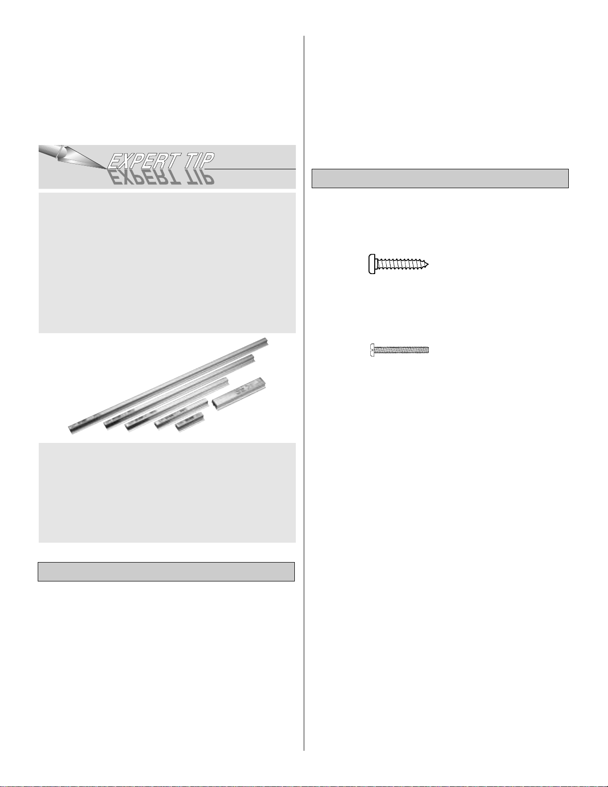
There are two types of screws used in this kit:
Sheet metal screws are designated by a number and
a length.
For example #6 x 3/4"
Machine screws are designated by a number, threads per
inch and a length.
For example 4-40 x 3/4"
When you see the term “test fit” in the instructions, it
means you should first position the part on the assembly
without using any glue, then slightly modify or “custom fit”
the part as necessary for the best fit. Do not glue until told
to do so.
When you see the term “fit and glue” in the instructions, it
means you should first position the part on the assembly
without using any glue, then modify or “custom fit” the
part as necessary for the best fit. Glue when you are
satisfied with the fit.
Whenever just “epoxy” is specified you may use either
30-minute epoxy or 6-minute epoxy. When 30-minute
epoxy is specified it is highly recommended that you use
only 30-minute epoxy because you will need the working
time and/or the additional strength.
Where you see the term “glue”, it is at your option to select
the thickness of CA with which you are most comfortable. If
the step indicates a particular thickness of glue, be sure to
use the thickness recommended for strength, penetration
and/or working time.
Several times during construction we refer to the “top” or
“bottom” of the model or a part of the model. For example,
during construction we tell you to “glue the top main spar” or
“trim the bottom of the former.” It is understood that the “top” or
“bottom” of the model is as it would be when the airplane is
right-side-up and will be referred to as the “top” even if the
model is being worked on upside-down. I.E. the “top” is always
the “top”, even when the fuse is being built upside-down.
Building Notes
Optional Supplies and Tools
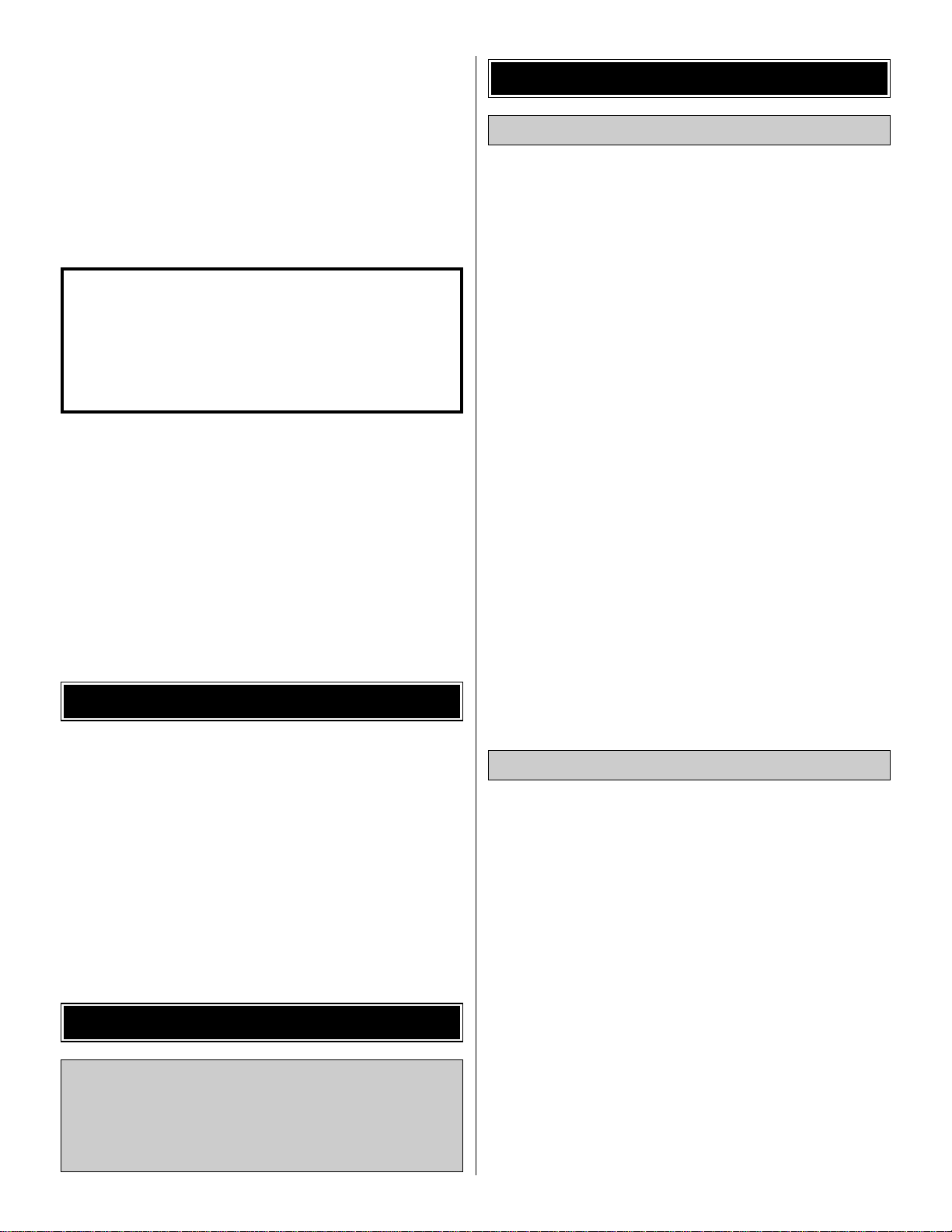
GPMR6169 Hand Sander-5.5" GPMR6170 Bar Sander-11"
GPMR6172 Bar Sander-22" GPMR6174 Bar Sander-33"
GPMR6176 Bar Sander-44"
GPMR6190 Multi-Sander-11" GPMR6191 Multi-Sander-22"
GPMR6180 80-Grit Sandpaper-12' roll
GPMR6183 150-Grit Sandpaper-12' roll
GPMR6184 180-Grit Sandpaper-12' roll
GPMR6185 220-Grit Sandpaper-12' roll
Made of durable, lightweight aluminum, Easy-Touch
™
Sanders have a uniquely contoured handle that lets you
work longer with less fatigue! The incredibly flat sanding
surface removes high spots with ease. The 5.5" Hand
Sander is ideal for small parts and tight spaces. Use the
11" - 44" Bar Sanders for larger areas. Take the
guesswork out of sanding curved or angled shapes with
the Easy-Touch Multi-Sander. Available in 11" and 22"
lengths. Easy-Touch adhesive-backed sandpaper is
already trimmed to these tools’ width...just cut it to length
and press in place. Available in 4 different grits.
Page 5
Elev = Elevator Fuse = Fuselage
LE = Leading Edge (front) LG = Landing Gear
Lt = Left Ply = Plywood
Rt = Right Stab = Stabilizer
TE = Trailing Edge (rear) " = Inches
1. Unroll the plan sheets. Reroll the plan sheets inside out
to make them lie flat.
2. Remove all parts from the box. As you do, determine the
name of each part by comparing it with the plan and the
parts list included with this kit. Using a felt-tip or ballpoint
pen, lightly write the part name or size on each piece to
avoid confusion later. Use the die-cut patterns shown on
page 6 to identify the die-cut parts and mark them before
removing them from the sheet. Save all leftovers. If any of
the die-cut parts are difficult to punch out, do not force them!
Instead, cut around the parts with a hobby knife. After
punching out the die-cut parts, use your bar sander or
sanding block to lightly sand the edges to remove any
die-cutting irregularities or slivers.
3. As you identify and mark the parts, separate them into
groups, such as fuse (fuselage), wing, fin, stab (stabilizer)
and hardware.
Zipper-top food storage bags are handy to store the small
parts as you sort, identify and separate them into
sub-assemblies.
Metric Conversion Chart
1” = 25.4mm (conversion factor)
1/64" = .4mm
1/32" = .8mm
1/16" = 1.6mm
3/32" = 2.4mm
1/8" = 3.2mm
5/32" = 4mm
3/16" = 4.8mm
1/4" = 6.4mm
3/8" = 9.5mm
1/2" = 12.7mm
5/8" = 15.9mm
3/4" = 19mm
1" = 25.4mm
2" = 50.8mm
3" = 76.2mm
6" = 152.4mm
12" = 304.8mm
15" = 381mm
18" = 457.2mm
21" = 533.4mm
24" = 609.6mm
30" = 762mm
36" = 914.4mm
Get Ready to Build
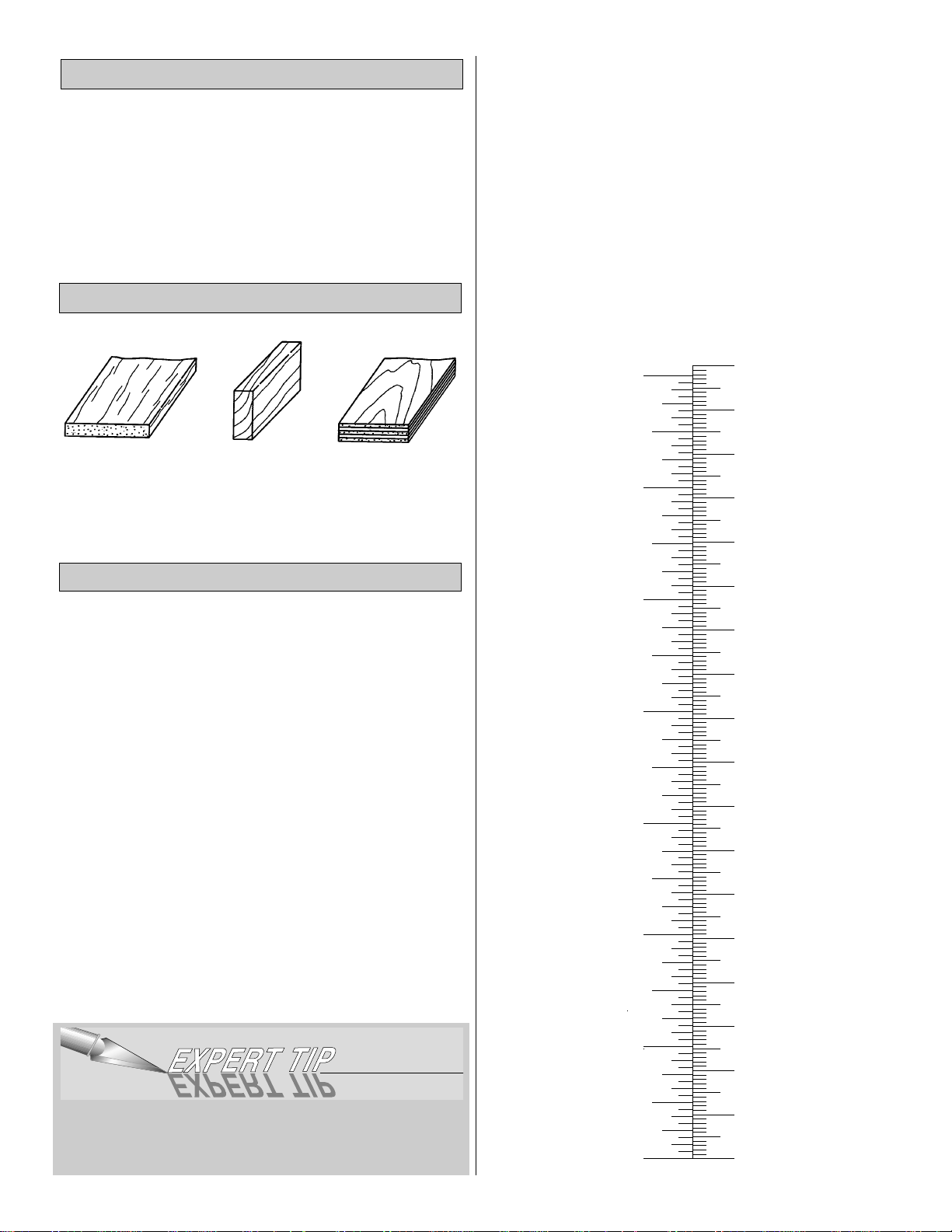
Balsa Basswood Plywood
Types of Wood
Common Abbreviations
5
Inch Scale
0" 1" 2" 3" 4" 5" 6" 7"
Metric Scale
0 10 20 30 40 50 60 70 80 90 100 110 120 130 140 150 160 170 180
Page 6
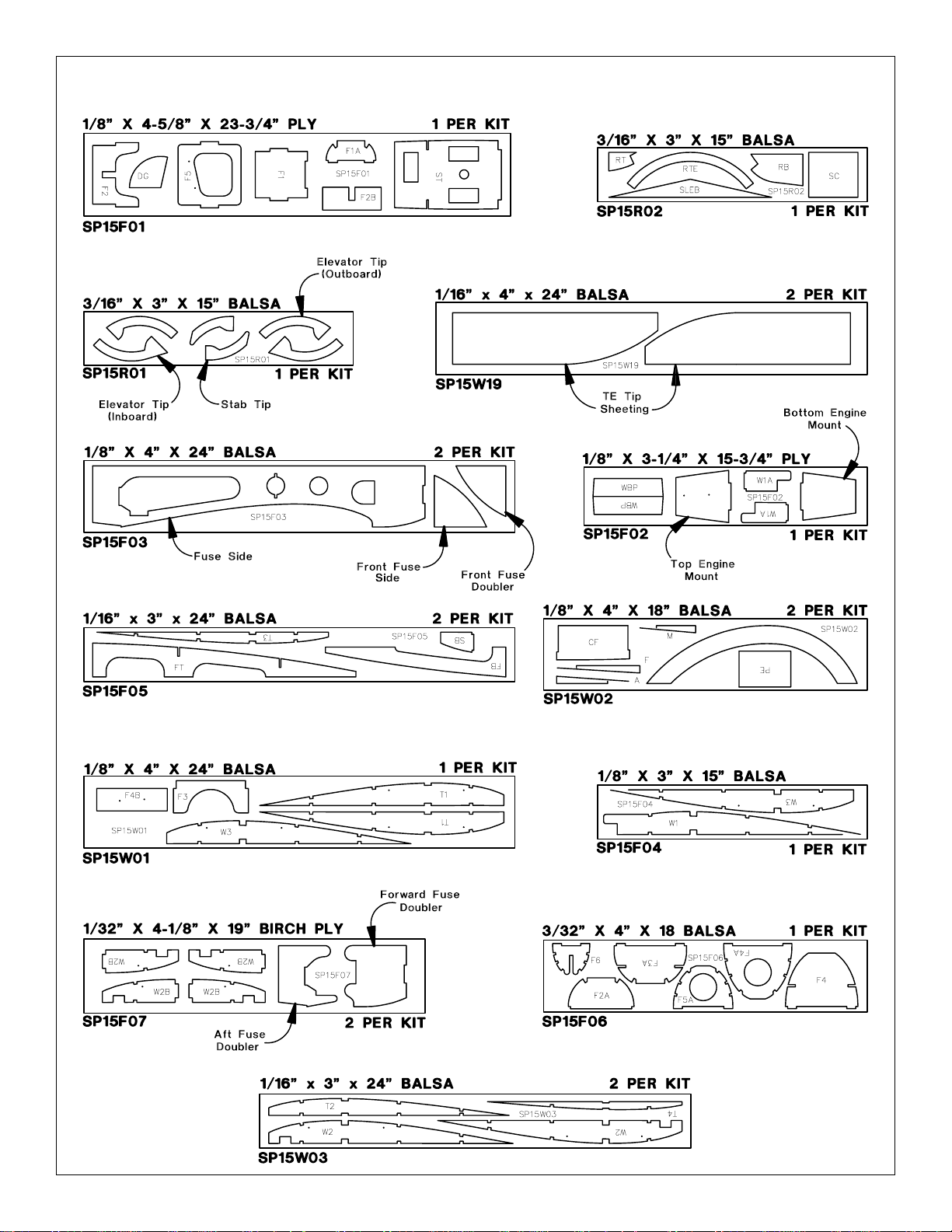
6
DIE-CUT PATTERNS
Page 7
You may remove the stabilizer and elevator drawing from
the plan by cutting along the dashed line. Don’t forget to
cover the plan with Great Planes Plan Protector™so the
glue won’t stick to the plan.
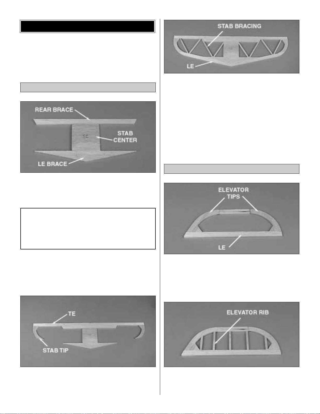
❏ 1. Pin the die-cut 3/16" balsa stab LE brace in position
over the plan. Glue the die-cut 3/16" balsa stab center to
the stab LE brace.
❏ 2. From a 3/16" x 1/2" x 24" balsa stick, fit and glue the
rear brace in place. Note: Save all the remaining pieces of
the sticks that you cut.
❏ 3. From a 3/16" x 1/2" x 24" balsa stick, fit and glue the
trailing edge to the rear brace.
❏4. Glue the die-cut 3/16" balsa stab tipsto the traili ng edge.
❏ 5. From a 3/16" x 1/2" x 24" balsa stick, fit and glue the
two leading edges in place.
❏ 6. From two 3/16" x 3/16" x 24" balsa sticks, fit and glue
the stab bracing in place.
❏ 7. Remove the pins and sand the top and bottom of the
stab smooth. Note: Be careful not to sand any dips in the
stab bracing.
❏ 8. Sand the leading edge and the tips to a rounded shape
as shown on the plan.
❏❏1. Pin the two die-cut 3/16" balsa elevator tips to the
plan. Note: There is a difference in the shape of the inboard
and outboard tips.
❏❏2. Using a 3/16" x 1/2" x 24" balsa stick, fit and glue the
leading and trailing edge in place.
❏❏3. Using a 3/16" x 3/16" x 24" balsa stick, fit and glue
the five elevator ribs in position.
❏❏4. Unpin the elevator half and set aside.
Build the Elevator
Note: Refrain from using excessive accelerator. Even
hours after it’s sprayed on, residual accelerator can
prematurely and unexpectedly cure the CA you use later
on nearby glue joints. Unless you must handle or remove
the part from the building board right away, we
recommend using no accelerator at all.
Build the Stab
BUILD THE TAIL SURFACES
7
Page 8
❏ 5. Repeat steps 1 through 4 to build the second
elevator half.
❏ 6. Pin one elevator half in place on the plan, making sure
the elevator is right side up. Position the second elevator
half over the plan, making sure it is a mirror image of the
pinned half. Use a straight edge, held against the LE of the
pinned down half, to ensure the elevator halves are aligned.
Pin the second half in place.
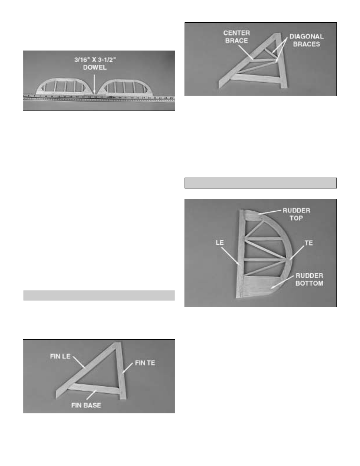
❏ 7. Trim the leading edges to accept the 3/16" x 3-1/2"
dowel. Glue the dowel to both halves with medium CA.
Remove the elevator from the building board.
❏ 8. Fill the area around the dowel with Hobbico HobbyLite
balsa-colored filler. Set the elevator assembly aside and let
the filler dry.
❏ 1. Cover the fin and rudder section of the plan with Great
Planes Plan Protector.
❏ 2. From a 3/16" x 1/2" x 24" balsa stick, fit and glue the
fin trailing edge, fin base and the fin leading edge. Note:
The fin trailing edge stops at the top of the stab. It does not
go to the bottom of the fuse.
❏ 3. From a 3/16" x 3/16" x 24" balsa stick, fit and glue the
center fin brace in postion.
❏ 4. From a 1/8" x 3/16" x 24" balsa stick, fit and glue the
two diagonal fin braces in place.
❏ 5. Remove the fin from the work surface and sand both
sides smooth.
Refer to this photo for the following 6 steps.
❏ 1. From a 3/16" x 1/2" x 24" balsa stick, cut and pin the
rudder leading edge in place on the plan.
❏ 2. Glue the die-cut 3/16" balsa rudder bottom and
rudder top to the rudder leading edge.
❏ 3. Glue the die-cut 3/16" balsa rudder trailing edge to
the rudder top and bottom.
❏ 4. From a 3/16" x 3/16" x 12" balsa stick, fit and glue the
two horizontal rudder braces in place.
❏ 5. From a 1/8" x 3/16" x 24" balsa stick, fit and glue the
three diagonal rudder braces in place.
❏ 6. Remove the rudder from the work surface and sand
both sides smooth.
Build the Rudder
Build the Fin
8
Page 9
❏❏1. Place the stab over its location on the plan. Lightly
mark the hinge locations on the trailing edge with a ball
point pen. Mark the hinge locations on the elevator in the
same manner.
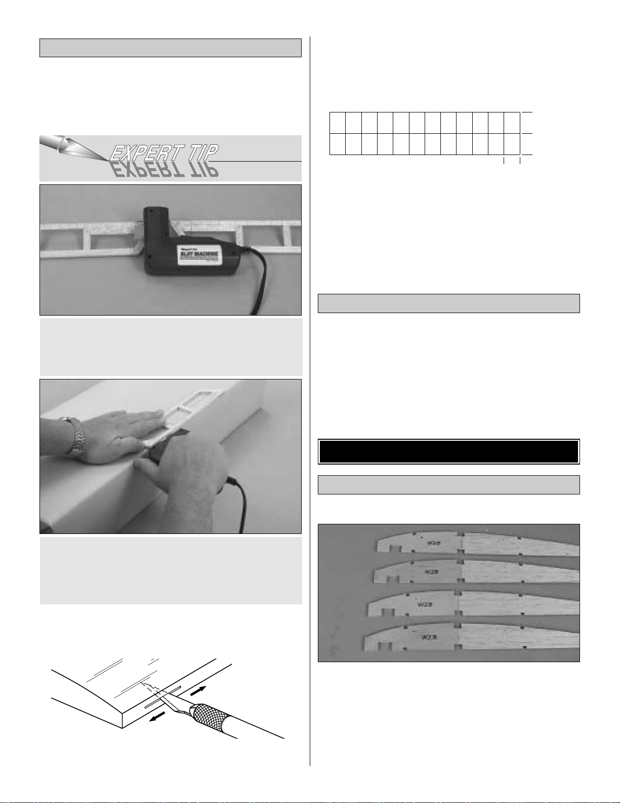
If you choose not to purchase a Slot Machine™you can
make the slots by following these instructions.
❏❏2. Cut the hinge slots in the elevator and stabilizer using
a #11 blade. Begin by carefully cutting a very shallow slit at
the hinge location to accurately establish the hinge slot.
Make three or four more cuts, going a little deeper each
time. As you cut, slide the knife from side to side until the slot
has reached the proper depth and width for the hinge.
❏❏3. Cut 3/4" x 1" hinges for the elevator from the
supplied 2" x 9" hinge material, then snip off the corners.
Temporarily join the elevator to the stab with the hinges,
adjusting any hinge slots if necessary so they all align. Do
not glue in the hinges until you are instructed to do so.
❏ 4. Repeat steps 1 through 3 to hinge the rudder and fin.
❏ 1. Shape the leading edge of the elevator and rudder to
a “V” as shown on the plan.
❏ 2. Sand both sides of the elevator assembly smooth.
❏ 3. Use a bar sander and 150-grit sandpaper to round the
tail surfaces, as shown on the plan.
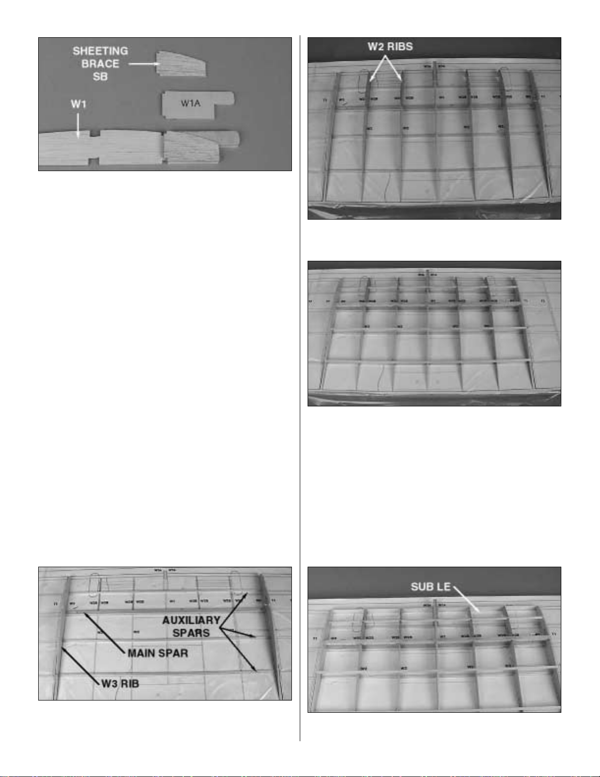
Note: All of the wing ribs have been partially die-cut at the bottom
of the trailing edge. Use a hobby knife to complete the die-cut.
❏ 1. Glue four die-cut 1/32" ply W2B’s to the four die-cut
1/16" balsa W2 ribs. Glue four more W2Bs to the other side
of the four W2 ribs. Note: Each of these rib assemblies is
now referred to as W2.
❏ 2. Drill two 1/8" holes at the punch marks in each of the
four W2 ribs. Drill two 1/8" holes at the punch marks in each
of the two die-cut 1/8" balsa W3 ribs.
Build the Wing Center Section
BUILD THE WING
Finish the Tail Surfaces
To cut the hinge slot, place the blades onto the wood
where you want the slot. Lightly press the teeth into the
wood. When you are satisfied with the location, press the
button on the handle and the blades will cut easily into the
balsa wood.
We have simplified the task of cutting hinge slots with the
introduction of the Great Planes Slot Machine™. This
simple electric tool cuts a perfect width slot for use with
CA hinges.
Hinge the Tail Surfaces
9
1"
1"
3/4"
Page 10
❏ 3. Glue a die-cut 1/8" ply W1A to the die-cut 1/8" balsa
W1 rib. Glue the die-cut 1/16" balsa Sheeting Brace SB to
W1A. Glue the second W1A and the second sheeting
support to the other side of the W1 rib. Note: This rib
assembly is now referred to as W1.
❏ 4. Lay the wing plan on the building board. Hint: Y ou may
cut the wing plan section from the plan. Don’t forget to cover
it with Great Planes Plan Protector.
❏ 5. Cut the two 1/4" x 3/8" x 24" balsa sticks to 21-3/16"
long, making two main spars. Pin the bottom main spar in
place over the plan. Note: The T-pins need to go into the
spar at an angle from the front so that they will not interfere
with the top spar or the shear webs.
❏ 6. Cut six 1/8" x 3/16" x 24" balsa sticks to 21-3/16" long,
making the auxiliary spars.
❏ 7. Postion three auxiliary spars over the plan. Note: Do
not pin them in place.
❏ 8. Making sure to keep the W3 ribs perpendicular to the
building board, position the ribs and glue them to the main
spar and the auxiliary spars.
❏9. Position and glue the W1 rib and the four W2 ribs in place.
❏ 10. Position and glue the 1/4" x 3/8" x 21-3/16" balsa top
main spar in the ribs.
❏ 1 1. Position and glue the 1/8" x 3/16" x 21-3/16" balsa top
auxiliary spars to the ribs.
❏ 12. From a 1/16" x 5/8" x 24" balsa sheet, cut two 107/16" long pieces, making two sub leading edges.
❏ 13. Position and glue both 10-7/16" sub leading edges to
the front edge of the ribs.
10
Page 11

❏ 14. Sand the top of the sub leading edge to the shape of
the ribs.
❏ 15. From the shaped 6-3/4" balsa TE filler block, cut, fit
and glue the two TE filler blocks in place.
❏ 16. From the 1/16" x 3" x 12" balsa sheet, cut, fit and glue
the six shear webs in place on the TE of the spars.
❏ 17. Position the 1/16" x 3" x 24" balsa TE sheeting,
aligning the trailing edge of the sheeting with the TE of the
wing shown on the plan. Glue it in place. Trim the excess
sheeting which extends outboard past ribs W3. Note: Be
sure to align it with the wing plan, not the aft end of the ribs.
❏ 18. From a 1/16" x 3" x 24" sheet, cut a 10-7/16" long LE
sheet. Position the LE sheet, aligning the rear of the LE
sheet with the center of the forward auxiliary spar and glue
it in place.
❏ 19. Remove the T-pins from the spar. From a 1/16" x 3"
x 30" balsa sheet, cut three 7-1/4" long center sheets. See
the Expert Tip which follows, then edge glue the center
sheets together. Fit, cut and glue this center sheet to the
W1 and W2 ribs as shown on the plan.
A. Use a metal straightedge as a guide to trim one edge
of both sheets.
HOW TO MAKE WING SHEETING
11
Page 12

❏ 20. Using two 1/16" x 1/4" x 24" balsa sticks, fit and glue
cap strips to the top edge of the four exposed ribs.
❏ 21. Trim the LE sheeting flush with the front of the sub
leading edge.
❏22. Remove the wing center section from the building board.
Sand the sheeting and the cap strips flush with both W3s.
❏ 23. Use a 1/4" x 1/2" x 24" balsa stick as your trailing edge
jig. Pin it to the plan, over the aft auxiliary spar. Position the
wing upside down over the plan, with the auxiliary spar aligned
with the trailing edge jig as shown in the photo. Weight the
middle of the wing to hold it in position. Hint: Ankle weights or
bar sanders with sealed bags of shot work very well.
❏ 24. Position a 1/16" x 3" x 24" balsa TE sheet aligned with
the top TE sheet previously applied. Glue it to the ribs, the
auxiliary spar and the filler block.
❏ 25. Select the two 4-7/8" long basswood landing gear
rails. Glue them into the W2 ribs with epoxy.
❏ 26. Glue the landing gear torque blocks to the top side
of the landing gear rails, flush with W2, as shown on the
plan.
❏ 27. Use a piece of chalk to mark the tops of the landing
gear rails. Position a 1/16" x 3" x 24" balsa LE sheet aligned
C. Turn the sheet over and apply weights on top of the sheet
to hold it flat. Apply thin CA sparingly to the seam between
the two pieces, quickly wiping away excess CA with a paper
towel as you proceed.
D. Turn the sheet over and remove the masking tape,
then apply thin CA to the seam the same way you did for
the other side.
E. Sand the sheet flat and smooth with your bar sander
and fresh 150-grit sandpaper.
B. Use masking tape to tightly tape the two sheets
together joining the trimmed edges.
12
Page 13

with the center of the forward auxiliary spar as you did with
the top sheeting. Press the sheet firmly against the landing
gear rails so that the chalk will mark the location of the
landing gear rails on the sheeting. Note: Be careful to hold
the sheet in position as you do so.
❏ 28. Remove the sheet from the wing. Cut out the areas
marked with chalk. Test fit the sheet onto the wing. When
satisfied with the fit, glue the sheet to the auxiliary spar, ribs,
sub leading edge and landing gear blocks with medium CA.
❏ 29. Use a 1/16" x 3" x 30" balsa sheet to sheet the center
of the panel. Use two 1/16" x 1/4" x 24" sticks to cap the ribs.
❏ 30. Trim and sand the leading edge sheeting flush with
the sub leading edge. Trim and sand the leading edge and
trailing edge sheeting flush with both W3s. Note: The
leading edge will be applied after the wings are joined.
❏ 31. Measure 1/2" outboard from the inboard end of the
gear rails. Drill a 5/32" hole through each rail, being careful
not to drill through the top of the wing.
❏❏1. Cover the right outer wing panel plan with Plan
Protector. Pin the die-cut 1/16" balsa TE sheetingin position.
❏❏2. From a 1/16" x 3" x 30" balsa sheet, cut three 4-1/8"
long pieces.
❏❏3. Edge glue one of the 4-1/8" sheets against the front
of the TE sheet. Glue a second and third sheet in position
as shown on the plan and the following photo. Trim the
width of the third sheet so that it aligns with the center of the
auxiliary spar.
❏❏4. From a 1/16" x 3" x 24" balsa sheet, cut a 11-7/16"
long LE sheeting. Edge glue the sheet against the sheet
you installed in step 3, aligned with the outboard end.
❏❏5. From a 1/16" x 1/4" x 24" balsa stick, cut and glue
cap strips in position over the plan. Note: The plan shows
the top T1 cap strip, not the bottom. Position the T1 cap
strip flush with the inboard edge of the LE and TE sheeting.
❏❏6. From a 1/16" x 3/8" x 24" balsa stick, cut two
11-7/16" long main spars. From two 1/16" x 3/8" x 24"
balsa sticks, cut two 8" long main spar doublers.
❏❏7. From three 1/8" x 3/16" x 24" balsa sticks, cut six
11-3/8" long auxiliary spars.
Build the Outer Wing Panels
13
Page 14

❏❏8. Glue one main spar doubler onto each main spar,
aligning one end of the doubler with the end of the main
spar. Note: From here forward, this combination will be
known as a spar. Set one spar aside for the top of this outer
wing panel.
❏❏9. Align one main spar over the plan with the doubler
at the inboard end of this outer panel. Glue it to the cap
strips and the sheeting.
❏❏10. Align the three auxiliary spars (cut in step 7) over
the plan with the 3/16" side against the plan. DO NOT glue
them at this time.
❏❏11. Select the 1/8" die-cut balsa T1 rib and the 1/16"
die-cut balsa T2 rib. Drill 1/8" holes through the punchmarks
in T1. Position T1 and T2 on the plan.
❏❏12. Test fit the auxiliary spars and main spar into the
ribs. When satisfied with the fit, use the die-cut 1/8" ply DG
gauge to set the angle of T1 and glue T1 in place. Use a
square to be sure T2 is vertical and glue it in place.
❏❏13. Position the 1/16" die-cut balsa T3 rib on the plan,
aligned with the inboard edge of the center sheeting. Trim
the rear auxiliary spar flush with the inboard edge of T3,
being EXTREMEL Y careful not to cut the TE sheeting. Glue
T3 in place, using a square to be sure it’s vertical.
❏❏14. Position the 1/16" die-cut balsa T4 rib on the
sheeting, aligned with the outboard edge of the sheeting.
Trim the two auxiliary spars flush with the inboard edge of
T4. Use a square to be sure T4 is vertical and glue it in
place. Glue the auxiliary spars to the sheeting and ribs.
❏❏15. Position the top main spar (you made in step 6) in
all 4 ribs, with the doubler facing the plan and the bottom
side of the inboard end of the main spar flush with T1. Note:
A little of the top of the main spar will extend past the
inboard end of T1. This will be sanded flush later.
14
Page 15

❏❏16. Insert the front and middle auxiliary spars into the
tops of the ribs, aligning the outboard ends flush with the
outboard edge of T4. Install the aft auxiliary spar in its
notches in ribs T1, T2 and T3, aligning the outboard end
halfway between T3 and T4 (we will trim the excess later).
Glue the main spar and the auxiliary spars in place.
❏❏17. From a 1/16" x 5/8" x 24" balsa stick, cut an
1 1-7/16" sub leading edge. Align the sub leading edge flush
with the outboard edge of T4 and glue in place. Note: Save
the leftover piece for the left outer panel.
❏❏18. Sand the sub leading edge to the shape of the ribs
as you did with the center wing panel.
❏❏19. Unpin the bottom TE sheet and lift the wing off
the plan.
❏❏20. Trim and sand the LE sheeting flush with the front
of the sub leading edge.
❏❏21. Position the top (die-cut) TE sheet, aligning it with
the edges of the bottom TE sheet. Glue it in place.
❏❏22. From the leftover 1/16" x 3" balsa sheet, cut three
4-1/8" long sheets and edge glue them in position as you
did with the bottom sheeting. Hint: Remember to trim the
third piece along the center of the front auxiliary spar.
❏❏23. From a 1/16" x 3" x 24" balsa sheet, cut an 1 1-7/16"
long LE sheet. Edge glue it in position as you did with the
bottom sheeting.
❏❏24. From a 1/16" x ¼" x 24" balsa stick, cut and glue
cap strips in position on T1 and T2. Hint: Align the top cap
strip on T1 flush with the inboard edge of T1.
❏❏25. Trim and sand the top LE sheeting flush with the
sub leading edge. Trim and sand the spars and sheeting
flush with T1 and T4. Note: Be careful not to change the
angle of T1.
❏❏26. Position and glue the die-cut 1/8" balsa wing tip,
aligning it with the trailing edge and flat on the building surface.
Note: The wing tip will not come all the way to the front of
the sub leading edge.
❏❏27. Position and glue the three die-cut 3/32" balsa tip
braces as shown on the plan.
Repeat steps 1-27 to build the left outer wing panel.
15
Page 16

❏❏1. From a 1/8" x 18" dowel, cut four 4" long wing joiners.
❏❏2. Slide the first wing joiner through the forward hole in
rib W3 (the right side of the wing center section) and the
forward hole in the first W2 until it is flush with the inboard
edge of W2. Slide the second wing joiner into the aft holes
in W2 and W3, aligned as you did the forward joiner. Glue
both wing joiners into W2 and W3. Lay Plan Protector over
the building surface and place the wing center section flat
on the Plan Protector.
❏❏3. Carefully slide the outer wing panel onto the two wing
joiners until flush with the center wing section. Support the
outboard tip of the outer wing panel 3-1/4" above the building
surface. Adjust the dowel holes slightly if required to properly
position the outer wing panel and to properly align the outer
wing panel to the wing center section. When satisfied with the
fit, glue the outer panel to the center section with epoxy and
glue the wing joiners to ribs T1 and T2. Note: Do not disturb
the wing until the epoxy has fully cured.
❏ 4. Repeat steps 1 through 3 to join the left outer panel to
the wing center section.
❏ 5. Sand all three sub leading edges flush with each other.
❏❏6. From a 3/8" x 3/4" x 24" balsa stick, cut a 10-3/8"
long leading edge for the right half of the center section.
Glue it to the sub leading edge and LE sheeting.
❏❏7. Sand a taper onto the leftover 3/8" x 3/4" x 13-5/8"
balsa leading edge for the right outer wing panel so that it
fits snugly against the center section leading edge. Glue it
in place.
❏❏8. Trim the outer panel leading edge flush with the
outboard edge of T4. Razor plane and sand the leading
edge on the outer panel and center section to the shape
shown on the plan.
❏ 9. Repeat steps 6 through 8, installing the leading edge
on the left half of the wing.
Finish the Wing
16
Page 17

❏1. Cover the fuse side view with Great Planes Plan Protector.
❏ 2. Glue two die-cut 1/32" ply fuse doublers to the inside
of each die-cut 1/8" balsa fuse side as shown. Label them
“right side” and “left side” on the insides of the fuse sides. It
is important that you have the fuselage sides in a mirrored
position to ensure that you build a left and a right side.
HINT: To help you recognize left from right fuse sides, set
the sides upright and pretend you are in the cockpit.
❏ 3. Pin the right fuse side in place over the plan.
❏❏4. From a 1/8" x 3/16" x 36" balsa stick, cut a 28-1/2"
long fuse main stringer. Glue it to the top of the right fuse
side with the 1/8" side against the building board.
❏❏5. From a 3/16" x 3/16" x 30" balsa stick, fit and glue the
bottom aft fuse stringer and the aft fuse brace in place.
❏❏6. Glue the die-cut 1/8" balsa pushrod exit plate in place.
❏❏7. From a 1/8" x 3/16" x 24" balsa stick, fit and glue the
four fuse braces in place.
❏ 8. Unpin the right fuse side from the plan and turn it over.
Cover the right fuse side with Plan Protector and pin the left
fuse side on top of the right fuse side. Note: The left side
is built the same as the right, except it is built over the right
fuse side, not the plan.
❏ 9. Repeat steps 4 through 7 to build the left fuse side.
❏ 10. Glue the two die-cut 1/16" balsa fuse top halves
together, making the fuse top. Glue the two die-cut 1/16"
balsa fuse bottom halves together, making the fuse bottom.
❏ 11. Cover the fuse top view with Plan Protector.
Assemble the Fuse Formers & Sides
BUILD THE FUSELAGE
17
Page 18

❏ 12. Position and pin the die-cut 1/8" ply servo tray on
the plan.
❏ 13. Glue the fuse top in place against the servo tray.
❏ 14. Align the aft end of the two fuse sides over the plan,
making sure to keep them perpendicular to the work
surface. When satisfied with the fit, glue the trailing edges
of the fuse sides together.
❏ 15. Fit and glue the shaped 2-3/4" long balsa tail post
in place.
❏ 16. Drill a 3/16" hole through each of the two punchmarks
in the die-cut 1/8" ply former F5 and the die-cut 3/32" balsa
former F4B.
❏ 17. Pull the fuse sides against the fuse top, fitting the diecut 1/8" balsa formers F3 and F5 as you go. Note: The
embossed labels on F3 and F5 face the front of the plane
and are upside down on the work surface at this time.
❏ 18. Confirm that the fuse sides are perpendicular to the
work surface with a square, then glue the fuse sides to the
formers and the fuse top.
❏ 19. Fit and glue the fuse bottom in place, aligning it with
the front edge of F5.
❏ 20. Keeping the fuse sides aligned over the plan, position
the die-cut 1/8" ply formers F1 and F2. Using a square to be
sure your fuse sides are vertical while still keeping them
aligned over the plan, glue F1 and F2 to the fuse sides.
❏ 21. Glue the die-cut 1/8" ply F2B former to the front of F2,
aligning the slots and the bottoms of the formers.
❏ 22. Laminate the two die-cut 1/8" ply wing bolt plates
(WBP) together.
18
Page 19

❏ 23. Use 6-minute epoxy to glue WBP to the fuse sides.
❏ 24. Position the die-cut 1/8" ply F4B former vertically and
flush with the front of the fuse top. Glue it in place.
❏ 1. Lightly sand the wing saddle area.
❏ 2. Fit the wing to the fuse. If the wing chord is too wide,
sand the TE of the wing until the wing fits cleanly in the fuse.
❏ 3. Stick a T-pin through the center of the aft end of the
fuselage bottom. Tie a string to the T-pin. Pull the string to
the TE of the wing tip and put a piece of masking tape on
the string near the wing tip. Mark an arrow on the tape, then
slide the tape on the string so the arrow aligns with the wing
tip. Swing the string over to the other tip and see if it aligns
with the same point. If it does not, shift the wing and mark
the new location of the tip by adjusting the position of the
tape on the string. Do this until the arrow on the string aligns
with both tips.
❏ 4. Measure 1" forward from the TE of the wing and draw
a line parallel to the TE across the width of the fuse.
❏❏5. Keeping the wing aligned with the fuse, drill a 5/32"
hole through the wing and the WBP on the line, 1/2" inside
the edge of the fuse side.
❏❏6. Remove the wing. Tap the hole in WBP with a 10-32
tap. Enlarge only the hole in the wing to 13/64".
❏ 7. Bolt the wing to the fuse with the one 10-32 x 2" nylon
bolt. Repeat steps 5 and 6, drilling and taping the second
bolt hole.
❏ 8. Harden the threads in WBP with thin CA. After the CA
has fully cured, retap the holes to clean up the threads.
Mount the Wing
19
Page 20

❏ 1. Laminate the two die-cut 1/8" ply engine mounts
together, with 6-minute epoxy, making sure to keep the punch
marks on the larger mount visible.
❏ 2. Draw a line from front to back on the engine mount,
using the punch marks as a guide.
❏ 3. Cut the template for your engine from the plan. Place
the template on the line you drew, aligning it with the front
of the engine mount. Trace around the edges of the
template onto the engine mount.
❏ 4. Using your tracing as a guide, cut the engine mount to
accept your engine.
❏ 5. Position the engine on the mount so there is a 1/16" gap
between the rear of the engine and the slot in the mount.
❏ 6. Mark the engine mount holes with a pencil lead or a
T-pin. Remove the engine from the mount and drill four
9/64" holes at your marks. Hint: For greater accuracy use
the Great Planes Dead Center™Engine Mount Hole Locator
(GPMP8130) to mark the locations of the bolt holes.
❏ 7. Use the four 4-40 x 3/4" bolts to pull the four 4-40 blind
nuts into the bottom of the engine mount or seat them with
a hammer.
❏ 8. Glue the blind nuts into the engine mount by wicking
thin CA around the outside edges. Note: Be careful not to
glue the bolts to the blind nuts.
Mount the Engine
20
Page 21

❏ 9. Remove the engine from the engine mount.
❏ 10. Place the fuselage, inverted, onto the building
surface. Position and glue the engine mount flush with F1.
❏ 11. Locate the two die-cut 1/8" balsa front fuse sides
and the two die-cut 1/8" balsa front fuse doublers. Paying
special attention to keep the engine mount and the fuse flat
on the work surface, glue the two front fuse sides in place
to the sides of the engine mount. Note: The front fuse
doublers are smaller than the front fuse sides.
❏ 12. Glue the front fuse doublers in place to the insides
of the front fuse sides.
❏ 13. Fuelproof the wood on the inside of the front fuse
doublers, the front of F1 and the bottom of the engine
mount. Hint: Fuel proof paint or epoxy thinned with alcohol
works well.
❏ 14. Using a piece of 1/8" x 3" x 12" balsa, sheet the front
bottom from F2 up to and overlapping the engine mount.
Note: Be sure the grain is running across the fuse bottom,
not along it.
❏15. A 1/2" drain hole should be positioned as shown above.
❏ 16. Position the engine on your mount and trim the front
bottom sheeting as necessary so the engine will fit properly
on the engine mount.
❏ 1. Sand the rear edge of the fuse flat as shown. Sand the
rest of the fuse smooth.
Mount the Tail
21
Page 22

❏ 2. Determine the location of the pushrod exit holes from
the plan. Use a hobby knife to sharpen one end of a piece
of 3/16" (outer diameter) brass tubing, then use this tubing
to cut the pushrod exit holes (you may use a 3/16" drill bit,
but the brass tube makes a much neater cut). Hint: You
may chuck the brass tube into your drill to aid in cutting
these holes.
❏ 3. From the 36" long gray outer pushrod tube, cut two 131/2" long pieces. Insert the 13-1/2" tubes through the holes
you just cut in the fuse side and through formers F5 and
F4B so that 1/4" extends past F4B and out the fuse sides.
❏ 4. Glue the tubes to the fuse sides, F5 and F4B with
thin CA.
❏ 5. Cut off the tubes at the exit points and sand them flush
with the fuse sides.
❏ 6. Mount the wing on the fuse. Trim the wing bolts off 1/8"
above the WBP.
❏ 7. Turn the plane right side up. Glue the die-cut 3/32
balsa former F6 vertically in its slots.
❏ 8. Accurately measure the trailing edge of the stabilizer
and mark the center point.
❏ 9. Lay the stab in position (the TE should be flush with the
TE of the fuse) with the center point lined up with the center
of the fuse. Carefully check the stab alignment by standing
directly behind the fuselage and “eyeballing” whether or not
the stab is parallel to the wing. Sand the stab saddle (a little
at a time!) until the stab aligns properly with the wing. Also,
using your string, measure from the stab tips to a center point
on the front of the fuse to make sure the stab is aligned.
❏ 10. Using 6-minute epoxy, glue the stab to the fuse. Hold
or pin it in proper alignment until the epoxy has fully cured.
Note: Wipe off any excess epoxy, with a cloth moistened
with alcohol, before it sets.
❏ 11. Carefully align the fin on the stab. The fin must be
positioned perpendicular to the stab and must line up
with the fuselage centerline EXACTLY! Sand the slot in
F6, if necessary to properly align the fin. Glue the fin in
place. Note: The turtle deck stringers and the turtle deck
top will also lock the fin into position.
❏ 12. Remove the wing from the fuse.
22
Page 23

❏ 1. Align the tabs on the bottom of the die-cut 3/32" balsa F4
and F4A formers. Laminate the formers with medium CA.
❏ 2. With F4A facing the rear of the plane, glue the laminated
F4 in place, keeping it perpendicular to the fuse top.
❏ 3. Keeping F5A perpendicular to the fuse top, glue it
in place.
❏ 4. Glue a 1/8" x 5/16" x 18" balsa turtle deck stringer
into the bottom left notches in F4A and F5A. Trim the TE of
the stringer so that it comes to a point at the TE of the fin.
Glue to F6 and the fin. Repeat this step for the other five
turtle deck stringers.
❏ 5. Using the full-size template on the plan, make the
turtle deck top from a 1/4" x 1-3/4" x 18" balsa sheet.
❏ 6. Glue the turtle deck top to the turtle deck formers and
the fin.
❏ 7. Glue the two die-cut 1/8" balsa cockpit floors (CF)
together, making sure the embossed label is up on one and
down on the other.
❏ 8. Fit and glue the cockpit floor and the die-cut 3/32 balsa
former F3A in place.
❏ 9. Glue the die-cut 1/8" ply former F1A in place, keeping
it vertical to the engine mount.
Build the Front Deck & Turtle Deck
23
Page 24

❏ 10. Glue the die-cut 3/32" balsa former F2A in place 4"
behind F1A.
❏ 1 1. Cut the 1/8" x 1/4" x 24" balsa stick in half, making two
front deck stringers. Position each stringer in the notches
in F1A, F2A and F3A and flush with F3A. Cut the excess off
flush with F1A.
❏ 12. Cut a 1/16" x 4" x 30" balsa sheet in half, making two
15" long front deck sheets.
❏❏13. Align the top of the sheet with the top of the front
deck stringer but with 1/4" excess overhanging the top of
the stringer. Carefully trim and shape the sheet until
satisfied with the fit. Note: The grain runs parallel to the
stringer, not the fuse top.
❏❏14. Glue the bottom edge of the sheet to the fuse top.
Liberally wet the outside of the sheeting by spraying it with
an ammonia/water mix. Gently bend the sheet until you can
position it in a smooth curve all the way to the stringer. Use
medium CA to glue the sheet to the formers and stringer.
❏ 15. Repeat steps 13 and 14 for the right side.
❏ 16. Sand the front deck sheeting flush with the top of the
front deck stringers.
❏ 17. Carefully trim the front deck sheet along the cockpit
area to have a nice rounded shape as shown in the photo.
❏ 18. Glue the 1/2" x 2-1/2" x 8-3/4" balsa front deck top
to formers F1A, F2A and F3A and to the front deck
stringers, leaving 1/4" overhanging F3A.
❏ 19. Carve and sand the front deck top to blend with the
rounded shape of the front deck sheet.
24
Page 25

❏ 20. Carve and sand the turtle deck top to blend with the
rounded shape of the turtle deck formers. Note: The turtle
deck top requires less shaping toward the fin.
❏ 21. Using leftover balsa, make fillets around the front of
the stab and lower turtle deck stringer.
Wow! Step back and take a good look. Pat yourself on the
back! You are completely finished framing your SlowPoke!
Nice work.
❏ 1. Place the engine on the mount. Mark former F1A for
two fuel line holes and one throttle pushrod hole. Remove
the engine and drill the two 1/4" fuel line and one 1/8"
pushrod holes.
❏ 2. Select the 24" white flex cable outer guide tube for the
throttle. Slide it through its hole in F1A until it extends
halfway between F2A and F3A. Use medium CA to glue it
into F1A. Cut it flush with the outside of F1A.
❏ 3. From leftover 1/8" ply, cut a throttle pushrod retainer.
Glue it in place against the fuse side as shown on the plan.
❏ 4. Mount the throttle servo as shown on the plan. Install
a Great Planes Screw-Lock Connector (provided) onto the
second hole of the throttle servo arm.
❏ 5. Solder the threaded coupler to the 24" long throttle cable
with silver solder. Screw a nylon clevis onto the coupler.
❏ 6. Mount the engine. Slide the throttle cable through the
guide tube you installed in step 2. Attach the clevis to the
throttle arm on the carb.
❏ 7. Cut the excess cable off 1" behind the Screw-Lock
Connector on the throttle servo. Insert the throttle cable
through the Screw-Lock Connector.
❏ 8. Cut the 35" pushrod wire (threaded on both ends) into
two 17-1/2" long pushrods. Screw a clevis at least 14 turns
onto one rod, making the rudder pushrod. Slide the pushrod
wire through the rudder pushrod guide tube, which is the
guide tube on the left side of the fuselage. Remove the
backing plate from a nylon control horn and connect the
horn to the clevis in the outer hole. Fit the rudder to the fin,
using the hinges to hold them in place. DO NOT GLUE.
❏ 9. Position the control horn on the rudder as shown in the
sketch and on the plan. Use a ballpoint pen to mark the
location of the control horn mounting holes and drill 3/32"
holes through the rudder at the marks. Temporarily mount
the control horn to the rudder with the backing plate and
2-56 x 5/8" screws.
Install the Servos & Make the Pushrods
25
Correct Incorrect
Page 26

Reference this photo for the next 5 steps.
❏ 10. Position the rudder servo in the left side of the servo
tray as shown on the plan. Mount the servo.
❏ 11. Center the rudder and position the servo arm
perpendicular to the servo case. Mark the pushrod where it
crosses the servo arm. Bend the pushrod and connect it to
the servo arm with a Faslink™. Trim the excess wire that
protrudes past the Faslink. Unhook the clevis and
temporarily remove the rudder.
❏ 12. Fit the elevators to the stabilizer, using hinges to hold
it in place. DO NOT GLUE the hinges in position at this time.
❏ 13. Screw a clevis onto the elevator pushrod wire at least
14 turns. Slide the pushrod through the elevator pushrod
guide tube on the left side of the fuselage. Position and
temporarily mount the elevator control horn to the right
elevator as you did with the rudder control horn.
❏ 14. Install the elevator servo as shown on the plan.
Position the servo arm square with the servo case and set
the elevators to neutral. Mark the pushrod where it crosses
the servo arm, bend it and connect it to the servo arm with
a Faslink. Trim the excess wire above the Faslink.
❏ 15. Mark the location of the tail gear wire on the rudder
and the nylon tail gear bearing on the fuselage.
❏ 16. Remove the rudder and elevators from the model.
Using a pen, draw lines around the control horns and
remove the control horns. Poke approximately a dozen
holes in each surface’s control horn location with the tip of
a hobby knife, or T-pin. Remove the hinges from each
surface, then use thin CA to harden the wood inside the
lines you drew where the control horns attach.
❏ 17. Drill a 7/64" hole 5/8" deep in the leading edge of the
rudder at the mark you made for the tail gear wire. Test fit
the tail gear wire in the rudder. Cut a slot in the trailing edge
of the fuse at the marks you made for the nylon tail gear
bearing. Without using any glue, test fit the rudder to the fin
with the tail gear wire. When satisfied with the fit, remove
and set it aside.
❏ 1. Remove all the pushrods and remove the hinges and
control horns from the elevators and rudder. Remove the
engine and any other hardware you may have installed.
❏ 2. Most of the model should be rough-sanded by now,
with all the tabs and rough edges sanded even. Fill all
dents, seams, low spots and notches with HobbyLite
™
Balsa
Colored Filler.
❏ 3. After the filler has dried, use progressively finer grades
of sandpaper to even all the edges and seams and smooth
all surfaces. Remove all balsa dust from the model with
compressed air or a vacuum with a brush followed by a
tack cloth.
Before you cover the fuselage, first apply 1/4" wide strips of
MonoKote film in the corners of the stab and fuse and the
fin and the fuse, then proceed to cover the fin and stab with
pre-cut pieces that meet in the corners and overlap the 1/4"
strips. Never cut the covering on the stab and fin after it
has been applied except around the leading and trailing
edges and at the tips. Modelers who cut covering on top of
the wood structure may cut through the covering and into
the stab or fin. This will weaken the structure to a point
where it may fail during flight.
After the model is covered, you must fuelproof the inside of
the front bottom sheeting and cockpit. You may do so with
fuelproof model paint, 30-minute epoxy thinned with
alcohol, or finishing resin.
1. Using the template on the plan as a guide, cut a
windshield from the supplied butyrate sheet.
2. Use canopy glue to adhere the windshield to the covering
in the position shown on the plan. Hint: A piece of pinstripe
tape along the contact area makes an attractive seam.
INSTALL THE WINDSHIELD
FUELPROOF THE MODEL
COVER THE MODEL WITH
MONOKOTE FILM
PREPARE FOR COVERING
26
Servo Horn
2-56 (.074")
Pushrod Wire
FasLink
1/16"
Page 27

1. Assemble your Great Planes 4 oz. fuel tank (not
included). Attach a 6" piece of fuel tubing to the top nipple,
which will attach to the muffler pressure tap. Assemble and
install the tank cap. Attach a second piece of 6" fuel tubing
to the main nipple in the center of the tank cap, which will
attach to the carburetor.
2. Feed the fuel lines through F1A. Hint: Mark on F1A which
line came from the top nipple and goes to the muffler and
which line came from the main nipple and goes to your carb.
3. Install the fuel tank. Cushion it from vibration and prevent
it from moving by surrounding the tank on all sides (and
front) with foam rubber. Leave a few inches of extra fuel
tubing in front of F1A. Use leftover ply to support the tank.
❏ 1. Cut a slot in the covering down the center of each
landing gear rail.
❏2. Fit one prebent wire landing gear wire into each gear rail.
❏ 3. Using two nylon gear retainers and four #2x3/8" sheet
metal screws, secure each gear wire as shown in the photo.
❏ 4. Using four 5/32" wheel collars (not supplied), install
your 3" wheels.
❏ 1. Start with the elevators and stab. Cut the covering from
the hinge slots–don’t just slit the covering but remove a
small strip the size of the hinge slot.
❏ 2. Drill a 3/32" hole 1/2" deep in the center of each hinge
slot. A high speed Dremel Tool works best for this. If you use
a regular drill, clean out the hinge slots with a #11 blade.
❏ 3. Without using any glue, fit the hinges in the elevators
or stab. Do not glue the hinges yet. As you join the
elevators to the stab, confirm that the hinges are equally
inserted in the elevators and the stab. Insert a small pin in
the center of the hinges to keep them centered.
❏ 4. Remove the pin and add 6 drops of thin CA to the
center of all the hinges on both the top and the bottom.
Do not use accelerator on any of the hinges. Do not glue
the hinges with anything but thin CA and do not attempt
to glue one half of the hinge at a time with medium or
thick CA. They will not be properly secured and the
controls could separate while the model is in flight.
Attach the Control Surfaces
FINAL HOOKUPS & CHECKS
INSTALL THE LANDING GEAR
INSTALL THE TANK
27
TEMPORARY PIN
TO KEEP HINGE
CENTERED
ASSEMBLE, THEN APPLY 6 DROPS
OF THIN CA TO CENTER
OF HINGE, ON BOTH SIDES
THE CA WICKS
ALONG THE "TUNNELS"
TO THE ENTIRE
HINGE SURFACE
Page 28

❏ 5. Prepare the hinge slots for the rudder as you did the
elevators. Join the rudder to the fin with the hinges and use
30-minute epoxy to simultaneously glue the tail gear wire in
the rudder and the tail gear bearing in the fuse. Do not glue
the nylon bearing to the rudder. Glue the hinges in
position with thin CA. NOTE: Petroleum jelly on the areas
where the tail gear bearing contacts the wire will ensure that
it does not glue to the tail gear wire or rudder.
❏ 1. Install the engine and hook up the fuel lines and throttle
pushrod.
❏ 2. Install a 1-1/4" tail wheel with a 3/32" wheel collar.
❏ 1. Reattach all control horns.
❏ 2. With the model inverted in the stand and using the plan
as a reference, locate the pushrod tube exits on the model.
Trim the covering from these openings. Reinstall the
pushrods and hook up the control surfaces.
❏ 3. Wrap the receiver in 1/4" (or thicker) foam. Wrap the
battery in 1/4" foam. Temporarily position them as shown on
the plan. Note: You will use these components to help set
your C.G.
NOTE: The balance and control throws for the
SlowPoke have been extensively tested. We are
confident that they represent the settings at which the
SlowPoke flies best. Please set up your model to the
specifications listed above. If, after you become
comfortable with your SlowPoke, you would like to
adjust the throws to suit your tastes, that’s fine. Too
much throw can force the plane into a stall, so
remember, “more is not better.”
Do not confuse this procedure with “checking the C.G.”,
which will be the next step in balancing your model.
A model which is not laterally balanced properly may exhibit
a variety of unpleasant tendencies, such as uncharacteristic
tip stalls. This aircraft, when balanced properly, has NO
such bad tendencies. Be sure to check the lateral balance
carefully as described to help ensure that the model
exhibits the same handling qualities of our prototypes.
❏ 1. With the wing level and attached to the model (and the
engine and muffler installed), lift the model by the propeller
shaft and the fin several times. Notice which wing tip drops.
Hint: You may need assistance to perform this step.
❏ 2. The wing which consistently drops is the heavy side.
Balance the model by adding weight to the other tip.
Balance the Model Laterally
BALANCE YOUR MODEL
We recommend the following control surface throws:
NOTE: The throws are measured at the widest part of
the elevators and rudder. Adjust the position of the
pushrods at the control/servo horns to control the
amount of throw. You may also use the ATV’s if the
transmitter has them but the mechanical linkages should
still be set so the ATV’s are near 100% for maximum
servo power and the best servo resolution (smoothest,
most proportional movement). Be sure to confirm your
surfaces move the correct direction.
High Rate Low Rate
ELEVATOR: 5/8" up 1/2" up
5/8" down 1/2" down
RUDDER: 2" left and right
NOTE: If the radio does not have dual rates, then set the
control surfaces to move between the high rate and low
rate throws.
Set the Control Throws
Final Servo & Receiver Installation
Install the Hardware
28
RADIO SETUP
ELEVATOR MOVES UP
4-CHANNEL
TRANSMITTER
4-CHANNEL
TRANSMITTER
4-CHANNEL
TRANSMITTER
RUDDER MOVES RIGHT
CARBURETOR WIDE OPEN
Page 29

NOTE: This section is VERY important and must NOT be
omitted! A model that is not properly balanced will be
unstable and possibly unflyable.
❏ 1. Mount the receiver switch in a convenient location that
will not interfere with the servos and pushrods inside
the fuselage.
❏ 2. Accurately mark the balance point on the top of the
wing on both sides of the fuselage. Use thin strips of tape or
a felt tip pen to make the marks. The balance point (CG) is
located 3-5/8" back from the leading edge where the
wing meets the fuse as shown in the sketch and on the
wing plan. Hint: Reference the full size wing plan to help you
locate the proper balance point. This is the balance point at
which the model should balance for your first flights. After
initial trim flights and when you become more acquainted
with your SlowPoke, you may wish to experiment by shifting
the balance up to 5/16" forward or back to change the
flying characteristics. Moving the balance forward may
improve the smoothness and stability but the model may
then require more speed for takeoff and make it more
difficult to slow for landing. Moving the balance aft makes
the model more agile. In any case, please start at the
location we recommend and do not at any time balance
your model outside the recommended range.
❏ 3. With the wing attached to the fuselage, all parts of the
model installed (ready to fly) and an empty fuel tank, hold
the model upside-down with the stabilizer level. Lift the
model at the balance point. If the tail drops when you lift,
the model is “tail heavy” and you must add weight* to the
nose to balance the model. If the nose drops, it is “nose
heavy” and you must add weight* to the tail to balance the
model. NOTE: Nose weight may be easily installed by using
a “spinner weight” or gluing lead weights to the firewall. Tail
weight may be added by using Great Planes (GPMQ4485)
“stick-on” lead weights.
❏ 4. Permanently mount your receiver and battery.
* If possible, first attempt to balance the model by changing
the position of the receiver battery and receiver. If you are
unable to obtain good balance by doing so, then it will be
necessary to add weight to the nose or tail to achieve the
proper balance point.
Follow the battery charging procedures in your radio
instruction manual. You should always charge the transmitter
and receiver batteries the night before you go flying and at
other times as recommended by the radio manufacturer.
Balance the propellers carefully before flying. An
unbalanced prop is the single most significant cause of
vibration. Not only may engine mounting screws vibrate out,
possibly with disastrous effect, but vibration may also
damage the radio receiver and battery . Vibration may cause
the fuel to foam, which will, in turn, cause your engine to run
lean or quit.
We use a Top Flite Precision Magnetic Prop Balancer in the
workshop and keep a Great Planes Fingertip Balancer in
our flight box.
Since you have chosen the SlowPoke we assume that you
are an experienced modeler. Therefore, you should already
know about AMA chartered flying fields and other safe
places to fly. If for some reason you are a relatively
inexperienced modeler and have not been informed, we
strongly suggest that the best place to fly is an AMA
chartered club field. Ask the AMA or your local hobby shop
dealer if there is a club in your area and join. Club fields are
set up for R/C flying and that makes your outing safer and
more enjoyable. The AMA address and telephone number
is in the front of this manual.
Find a Safe Place to Fly
Balance the Propeller
Charge the Batteries
At this time check all connections including servo arm
screws, Faslinks, clevises and servo wires. Make sure you
have installed the silicone retainers on all the clevises.
PREFLIGHT
Balance the Model Fore & Aft (CG)
29
Page 30

If a club and flying site are not available, find a large, grassy
area at least 6 miles away from houses, buildings and
streets and any other R/C radio operation like R/C boats and
R/C cars. A schoolyard may look inviting but is too close to
people, power lines and possible radio interference.
If you are not thoroughly familiar with the operation of R/C
models, ask an experienced modeler to inspect your radio
installation and confirm that all the control surfaces respond
correctly to transmitter inputs. The engine operation must
also be checked by confirming that the engine idles reliably
and transitions smoothly and rapidly to full power and
maintains full power indefinitely . The engine must be “brokenin” on the ground by running it for at least two tanks of fuel.
Follow the engine manufacturer’s recommendations for
break-in. Make sure all screws remain tight, that the hinges
are secure and that the prop is on tight.
Whenever you go to the flying field, check the operational
range of the radio before the first flight of the day. First,
make sure no one else is on your frequency (channel). With
your transmitter antenna collapsed and the receiver and
transmitter on, you should be able to walk at least 100 feet
away from the model and still have control. While you work
the controls have a helper stand by your model and tell you
what the control surfaces are doing.
Repeat this test with the engine running at various speeds
with a helper holding the model. If the control surfaces are
not always responding correctly , do not fly! Find and correct
the problem first. Look for loose servo connections or
corrosion, loose bolts that may cause vibration, a defective
on/off switch, low battery voltage or a defective cell, a
damaged receiver antenna, or a receiver crystal that may
have been damaged from a previous crash.
NOTE: Failure to follow these safety precautions may
result in severe injury to yourself and others.
Keep all engine fuel in a safe place, away from high heat,
sparks or flames, as fuel is very flammable. Do not smoke
near the engine or fuel. Remember that the engine exhaust
gives off a great deal of deadly carbon monoxide. Do not
run the engine in a closed room or garage. Get help from
an experienced pilot when learning to operate engines.
Use safety glasses when starting or running engines.
Do not run the engine in an area of loose gravel or sand; the
propeller may throw such material in your face or eyes.
Keep your face and body as well as all spectators away
from the plane of rotation of the propeller as you start and
run the engine.
Keep ALL items away from the prop, including: radio neck
straps, loose clothing, shirt sleeves, ties, scarves, long hair
or loose objects such as pencils, screw drivers that may fall
out of shirt or jacket pockets into the prop.
When using a “chicken stick” or electric starter, follow
instructions supplied with the starter or stick. Make certain
the glow plug clip or connector is secure so that it will not
pop off or otherwise get into the running propeller.
Make all engine adjustments from behind the rotating
propeller.
The engine gets hot! Do not touch it during or after
operation. Make sure fuel lines are in good condition so fuel
will not leak onto a hot engine causing a fire.
To stop the engine, cut off the fuel supply by closing off the fuel
line or follow the engine manufacturer’s recommendations. Do
not use hands, fingers or any body part to try to stop the engine.
Do not throw anything into the prop of a running engine.
Read and abide by the following Academy of Model
Aeronautics Official Safety Code:
General
1. I will not fly my model aircraft in sanctioned events, air
shows, or model flying demonstrations until it has been
proven to be airworthy by having been previously
successfully flight tested.
2. I will not fly my model aircraft higher than approximately
400 feet within 3 miles of an airport without notifying the
airport operator. I will give right of way to and avoid flying in
the proximity of full scale aircraft. Where necessary an
observer shall be used to supervise flying to avoid having
models fly in the proximity of full scale aircraft.
3. Where established, I will abide by the safety rules for the
flying site I use and I will not willfully and deliberately fly my
models in a careless, reckless and/or dangerous manner.
7. I will not fly my model unless it is identified with my
name and address or AMA number, on or in the model.
9. I will not operate models with pyrotechnics (any device
that explodes, burns, or propels a projectile of any kind)
AMA Safety Code (excerpts)
Engine Safety Precautions
Range Check Your Radio
Ground Check the Model
30
Page 31

Radio control
1. I will have completed a successful radio equipment ground
check before the first flight of a new or repaired model.
2. I will not fly my model aircraft in the presence of
spectators until I become a qualified flier, unless assisted by
an experienced helper.
3. I will perform my initial turn after takeoff away from the
pit or spectator areas and I will not thereafter fly over pit or
spectator areas, unless beyond my control.
4. I will operate my model using only radio control
frequencies currently allowed by the Federal
Communications Commission.
The SlowPoke does not possess the self-recovery
characteristics of a primary R/C trainer and should only be
flown by experienced RC pilots. Have fun!
Takeoff on “high” rates if you have dual rates on your
transmitter. For all models it is good practice to gain as
much speed as the length of the runway will permit before
lifting off. This will give you a safety margin in case the
engine quits. When you initially advance the throttle and the
tail begins to lift, the SlowPoke will begin to turn to the left
(due to the torque of the engine–a characteristic of all
taildraggers). Be prepared for this by applying sufficient
right rudder to keep the SlowPoke running straight down
the middle of the runway (or flying field). The left turning
tendency will decrease as the plane picks up speed. Be
sure to allow the tail to rise off the ground before lifting the
model into the air. Depending on the surface you are taking
off from, you will need to apply little or no up elevator until
flying speed is reached. Don’t hold the tail on the ground
with too much up elevator, as the SlowPoke will become
airborne prematurely and may stall. When the plane has
gained enough flying speed to safely lift off, gradually and
smoothly apply up elevator and allow the model to climb at
a shallow angle (do not yank the model off the ground into
a steep climb!)
We recommend that you take it easy with your SlowPoke
for the first several flights, gradually “getting acquainted”
with this Sunday flier as your engine gets fully broken-in. If
you feel as though you have your hands full, keep this one
thing in mind: pull back on the throttle stick to slow the
model down. This will make everything happen a little
slower and allow yourself time to think and react. Add and
practice one maneuver at a time, learning how the
SlowPoke behaves in each. The high rates are primarily for
take offs and landings. For smooth flying and normal
maneuvers, use the low rate settings as listed on page 28.
Sometime well before it’s time to land you should climb your
SlowPoke to a safe altitude and cut the throttle to an idle
and check out the model’s low speed characteristics. Do
this a few times so you know what to expect upon landing.
When it’s time to land, fly a normal landing pattern and
approach. Keep a few clicks of power on until you are over the
runway threshold. For the first few landings, plan to land
slightly faster than stall speed and on the main wheels, as this
is the easiest way to land your SlowPoke. Later, with a little
practice you will find you can make slow 3-point landings.
Have a ball! But always remember to think about your
next move and plan each maneuver before you do it.
Impulsively “jamming the sticks” without any thought
is what gets most fliers in trouble rather than lack of
flying skill.
Landing
Flight
Takeoff
CAUTION (THIS APPLIES TO ALL
R/C AIRPLANES): If,
while flying, you notice any unusual sounds, such as a
low-pitched “buzz”, this may indicate control surface
“flutter”. Because flutter can quickly destroy components
of the airplane, any time you detect flutter you must
immediately cut the throttle and land the airplane! Check
all servo grommets for deterioration (this may indicate
which surface fluttered) and make sure all pushrod
linkages are slop-free. If it fluttered once, it will probably
flutter again under similar circumstances unless you can
eliminate the slop or flexing in the linkages. Here are
some things which can result in flutter: Excessive hinge
gap; Not mounting control horns solidly; Sloppy fit of
clevis pin in horn; Elasticity present in flexible plastic
pushrods; Side-play of pushrod in guide tube caused by
tight bends; Sloppy fit of Z-bend in servo arm; Insufficient
glue used when gluing in the elevator joiner wire or
aileron torque rod; Excessive flexing of aileron, caused by
using too soft balsa; Excessive “play” or “backlash” in
servo gears; and Insecure servo mounting.
FLYING
31
Page 32

TWO-VIEW
 Loading...