

Page 1
FUN-ONE
INSTRUCTION BOOK
WARRANTY
Great Planes Model Manufacturing Co., Inc. guarantees this kit to be free of defects in both material and workmanship at the date of purchase. This warranty does not cover any component parts damaged by use or modification. In
no
case
shall
Great Planes' liability exceed the original cost
to change or modify this warranty without notice.
In that Great Planes has no control over the final assembly or material used for final assembly, no liability shall be
assumed nor accepted for any damage resulting from the use by the user of the final user-assembled product.
By the act of using the user-assembled product the user accepts all resulting liability.
If the buyer is not prepared to accept the liability associated with the use of this product, he is advised
to immediately return this kit in new and unused condition to the place of purchase.
READ THROUGH THIS INSTRUCTION BOOK FIRST. IT CONTAINS IMPORTANT
INSTRUCTIONS AND WARNINGS CONCERNING THE ASSEMBLY AND USE OF THIS MODEL.
P.O. BOX 788 URBANA, ILLINOIS 61801 217/367-2069
FUN1P02
of
the purchased kit. Further, Great
Planes
reserves
the
right
Page 2

TABLE OF CONTENTS
INTRODUCTION
Precautions
Decisions You Must
Make Now
Other Items Required
Supplies and Tools Needed ..... 4
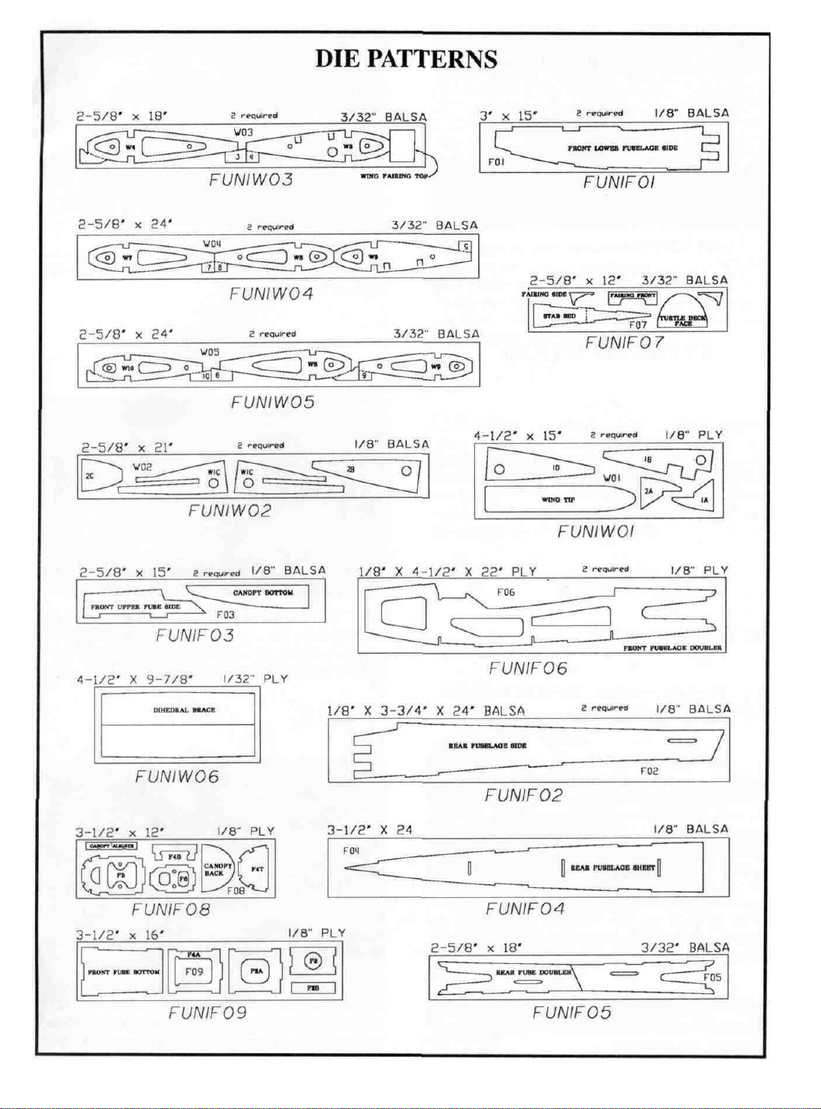
Die Patterns
Abbreviations
Types
Get Ready to
TAIL FEATHERS
Build the Stabilizer and
Build the Fin and Rudder ....... 8
Temporarily Install the Hinges ...9
FUSELAGE ASSEMBLY
Prepare Fuse Sides
Prepare Firewall
Assemble the Fuselage
WING ASSEMBLY
Build
Join
Sheet the Leading Edges
Add the Center Sheeting
Install Aileron Torque Rods ..... 25
Install Ailerons ............... 26
FINAL
Install
Install
Mount Stabilizer
of
Elevators .................. 6
the Wing Panels
the Wing
ASSEMBLY
Landing
Engine
Fit Fuel Tank and
Fuelproof Tank Compartment .. 28
.................
Wood
.............3
.................
.........
.................
................
...............
Build
Panels
................
...........
.............6
......
...........
.............
........
...........16
.........
..........
......
.......
...........27
Gear
.........
and
Fin
.......
3
4
4
5
6
6
6
10
10
11
11
16
18
22
24
.27
27
29
Shaping and Sanding ......... 31
INSTALL PUSHRODS AND
RADIO COMPONENTS
One Aileron Servo
Two Aileron Servos
Rudder, Elevator and
Throttle Servos ............. 32
Control Surface Throws ........ 33
Install Receiver, Switch
and Battery ................ 33
FINISHING .................34
Balance the Airplane Laterally ... 34
Final
Sanding
Covering ................... 34
Attach the Wing Tips .......... 34
Glue the Hinges .............. 35
Glue Canopy in Place
Wing Seating ................ 36
Balance Your Model ........... 36
Final Hookups and Checks ..... 36
PRE-FLIGHT
Charge the Batteries .......... 37
Find a Safe Place to Fly
Ground Check the Model
Range Check
Engine Safety Precautions ..... 37
AMA SAFETY CODE
FLYING
Takeoff ..................... 38
Flying ......................38
Caution .................... 39
Landing .................... 39
....................38
................37
............
................
Your
Radio
.......
...........
.........
.......
.......
......
.........38
31
31
31
34
35
37
37
37
Install
Build
Canopy
the Wing
...............
Fairing
.........
30
30
2-VIEW ....................39
PARTS LIST
2
................40
Page 3

WARNING! THIS IS NOT A TOY!
THIS IS NOT A BEGINNER'S AIRPLANE!
This R/C kit and the model you will build is not a toy! It is capable of serious bodily harm and property
damage. IT IS YOUR RESPONSIBILITY AND YOURS ALONE to build this kit correctly, properly install
all R/C components and flying gear (engine, tank, pushrods, etc.) and to test the model and fly it only with
experienced, competent help, using common sense and in accordance with all safety standards as set
down in the Academy of Model Aeronautics Safety Code. It is suggested that you join the AMA and become.
properly insured before you attempt to fly this model. IF YOU ARE JUST STARTING R/C MODELING,
CONSULT YOUR LOCAL HOBBY SHOP OR WRITE TO THE ACADEMY OF MODEL AERONAUTICS
TO FIND AN EXPERIENCED INSTRUCTOR IN YOUR AREA.
Academy of Model Aeronautics
1810 Samuel Morse Dr.
Reston, VA 22090 (703)435-0750
INTRODUCTION
Congratulations! Thank you for purchasing the Great
Planes FUN-ONE!
The Great Planes FUN-ONE defines a new type of sport
airplane. Its sleek looks arc not characteristic of the type of
planes that are as maneuvcrable as the FUN-ONE. This
state-of-the-art kit will provide you with many hours of
enjoyment from this point on - even the construction is FUN!
So lets begin.
NOTE: This is not a beginner's airplane! While the FUNONE is easy to build and flies great, we must discourage you
from selecting this kit as your first R/C airplane. It is highly
maneuverable, and lacks the self-recovery characteristics of
a good basic trainer such as the Great Planes PT Series
airplanes. On the other hand, if you have already learned the
basics of R/C Flying and you are able to safely handle an
"aileron trainer" airplane such as the Great Planes Trainer
Series or Big Stick Series airplanes, the FUN-ONE is an
excellent choice.
Please inspect all parts carefully before starting to
build! If any parts are missing, broken or defective, or if
you have any questions about building or flying this
airplane, please call us at (217) 367-2069 and we'll be glad
to help. If you are calling for replacement parts, please
look up the part numbers and the kit identification
number (stamped on the end of the carton) and have them
ready when calling.
PRECAUTIONS
1. You must build the plane according to the plans and
instructions. Do not alter or modify the model, as doing
so may result in an unsafe or unflyable model. In a few
cases the plans and instructions may differ slightly from
the photos. In those instances you should assume the plans
and written instructions are correct.
2. You must take time to build straight, true and strong.
3. You must use a proper R/C radio that is in first class
condition, the correct ci/.cd engine and correct compo-
nents (fuel tank, wheels, etc.) throughout your building
process.
4. You must properly install all R/C and other components
so that the model operates properly on the ground and in the
air.
5. You must test the operation of the model before the first
and each successive flight to insure that all equipment is
operating, and you must make certain that the model has
remained structurally sound. Be sure to check the nylon
clevises often, and replace if they show signs of wear.
6. You must fly the model only with the competent help of
a well experienced R/C pilot if you are not already an
experienced and knowledgeable R/C pilot at this time.
Note: We, as the kit manufacturer, can provide you with a
top quality kit and great instructions, but ultimately the
quality and fly-ability of your finished model depends on how
you build it; therefore, we cannot in any way guarantee the
performance of your completed model, and no representations arc expressed or implied as to the performance or safely
of your completed model.
Remember: Take your time and follow directions to end
up with a well-built model that is straight and true.
3
Page 4

DECISIONS YOU MUST MAKE NOW
ENGINE AND MOUNT SELECTION
The recommended engine size range is as follows:
.25 - .40 cubic inch displacement 2-cycle
.40 -.50 cubic inch displacement 4-cycle
NOTE: There arc several "High Power" .25 to .34 size
engines available which have as much power has
some .40 size engines yet weigh about the same as
most .25 size engines. We highly recommend cither
the OS Max .32 or the Super Tigrc G34. The FUNONE can structurally handle hot .40 size engines but
be careful about using heavy engines. The short tail
moment and swept wing makes it easy to end up with
a nose heavy model!
This kit includes a Great Planes MM19 engine
mount that fits most .20 - .34 (2-cyclc) engines. If you
prefer, you may purchase a custom engine mount
made specifically for your engine (check with your
hobby dealer), or you may choose to install shock-absorbing rubber-cushioned mounts.
SELECTION OF WHEELS
To save weight, we recommend using lightweight
foam rubber wheels.
2-3/4" diameter main wheels are recommended.
The larger the diameter the more they will absorb
hard landings and the better they will roll on grass
fields). If you build it with tricycle landing gear, the
nose wheel should be 1/4" smaller than the main
wheels.
A 1-1/4" diameter tailwheel is recommended.
RADIO INSTALLATION
The FUN-ONE is capable of using computer radios and other radios with mixing functions to provide flapcron type control. This type of mixing uses
a separate servo for each aileron and allows both ailerons to move in relation to the elevator. The
flapcrons will drop when up elevator is applied, and
vicc-vcrsa, which enables the plane to perform very
tight maneuvers and also enhances its slow flight
capabilities. This setup also provides Ihc most precise flight characteristics since The ailerons are hooked
directly to the servo with the control horn in the
middle of the aileron (very little slop).
If you have a radio without mixing capabilities
you will normally install only one servo in the center
of the wing. NOTE: If you arc going to use a high
power .40 size engine you should consider using two
aileron servos connected by a Y-harness to achieve
the precise control offered by this set-up. There is
also much less chance of aileron flutter with two
servos.
There are several places in the instructions which
alert you to perform different steps depending on the
setup you choose. You might also consider installing
the servo rails and tubes for two servos even though
you may not plan on using two servos right now.
They do not add much weight and they will be there
if you ever need them.
OTHER ITEMS REQUIRED
0 Four-channel radio with 4 servos (A radio with at least
five channels, 5 servos and mixing capabilities is
required if flaperons will be used).
0 Propellers (see engine instructions for recommended
sizes).
0 Spinner (2" diameter)
0 Fuel Tank (6 ounce)
0 5/32" Wheel Collars (2 - for tricycle)
0 3/32" Wheel Collars (2 - for taildragger
0 2 Rolls Monokote covering (or similar)
0 Silicone Fuel Tubing (std. size)
0 Wing Seating Tape (or silicone sealer ... see
instructions)
0 Latex Foam Rubber Padding (1/4" thick)
0 Dubro "E-Z Connector" (or equivalent)
0 Flex-Cable Pushrod for Throttle (& Nosegear)
SUPPLIES AND TOOLS NEEDED
0 2 oz. Thin CA Adhesive
0 2 oz. Medium or Thick CA Adhesive
0 2.5 oz.. 5-Minute Epoxy
0 Hand or Electric Drill
0 Drill Bits: 1/16", 5/64", 3/32", 7/64",
9/64", 13/64", 7/32", and 1/4"
0 Sealing Iron
0 Heat Gun
0 Hobby Saw (Xacto Razor Saw)
0 Xacto Knife, #11 Blades
0 Pliers
0 Screw Drivers
0 T-Pins
0 Straightedge
0 Masking Tape (Required for construction)
0 Sandpaper (coarse, medium, fine grit)*
0 T-Bar Sanding Block (or similar)
0 Waxed Paper
0 Lightweight Balsa Filler
0 1/4-20 Tap, Tap Wrench
0 Vaseline Petroleum Jelly
0 Dremel Moto Tool or similar (optional)
*NOTE: On our workbench, we have four 11" T-Bar sanders,
equipped with #50, #80, #100 and #150-grit sandpaper. This setup
is all that is required for almost any sanding task. We also keep
some #320-grit wet-or-dry sandpaper handy for finish sanding
4 before covering.
Page 5
5
Page 6
COMMON ABBREVIATIONS USED IN
THIS BOOK AND ON THE PLANS:
TAIL FEATHERS
Elev = Elevator
Fuse
= Fuselage
LE = Leading Edge
•LG = Landing Gear
Lt=Left
Ply = Plywood
RI = Right
Stab = Slabilizer
TE = Trailing Edge (rear)
" =Inches
Tri = Triangle Stock
(front)
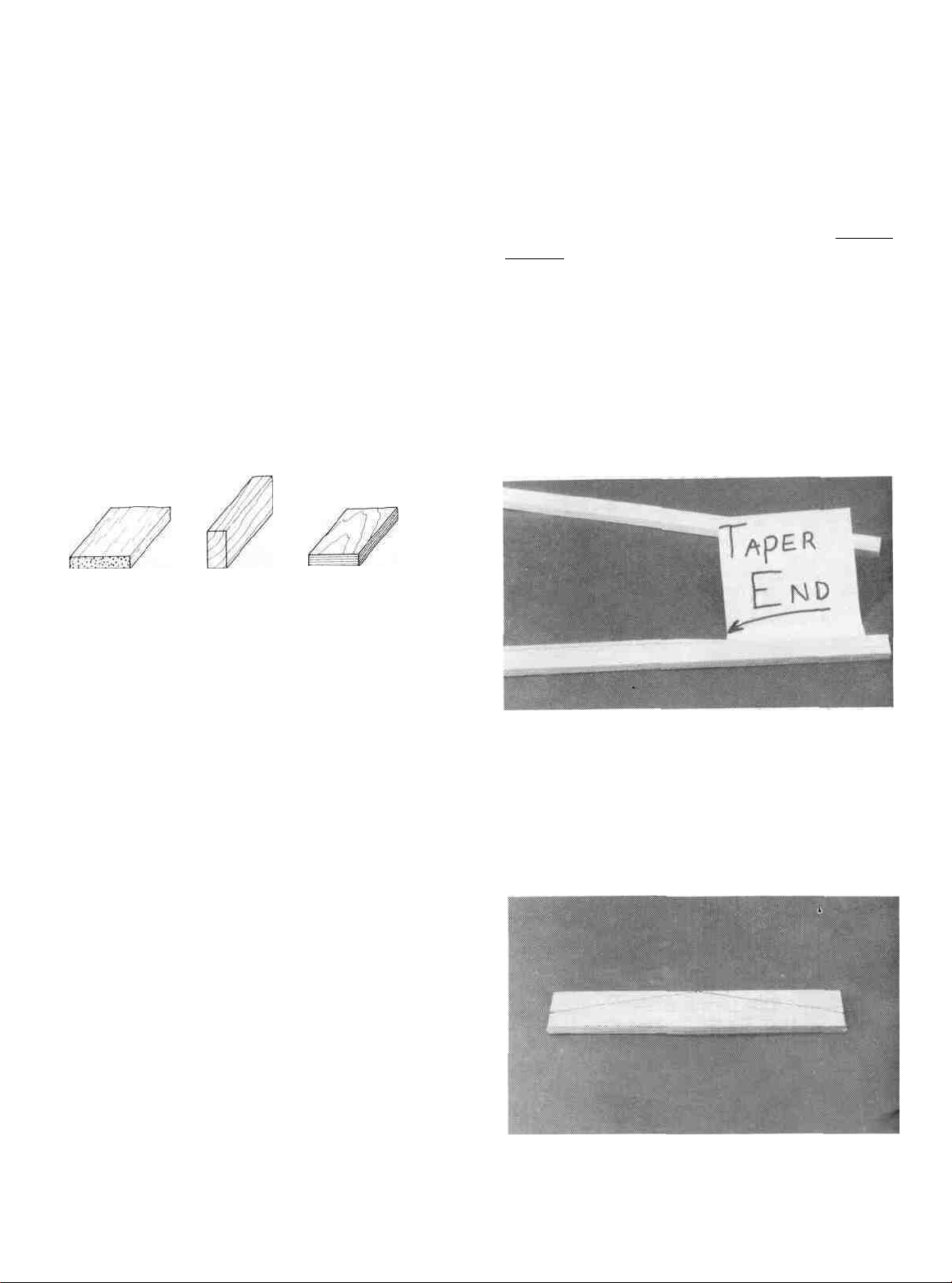
TYPES OF WOOD
BUILD THE STABILIZER AND
ELEVATORS
D 1. Tape the fuselage plan down to your flat work
surface. Tape a piece of waxed paper over the stab and
elevator portion of the plan.
D 2. Cut the stab leading and trailing edges from the
1/4" x 1/2" x 30" stick (FUN1S01). They can be cut
slightly oversize since we will sand them to the correct
length later.
GET READY TO BUILD
D 1. Unroll the plan sheets. Re-roll the plans inside
out to make them lie flat.
D 2. Remove all parts from the box. As you do, figure
out the name of each part by comparing it with the plans
and the parts list at the back of this book. Using a felt lip
pen, write the part name or size on each piece to avoid
confusion later. Use the die-cut patterns shown on page 5
to identify the die-cut parts and mark them before punching out. Save all scraps. If any of the die-cut parts are
difficult to punch out, do not force them! Instead, first cut
around the parts with an Xacto knife. After punching out
the die-cut parts, use your T-Bar or sanding block to
lightly sand the edges to remove any die-cutting irregu-
larities.
D 3. As you identify and mark the parts, separate them
into groups, such as fuse (fuselage), wing, fin and stab
(slabilizer), and hardware.
D 3. Taper both ends of the 1/8" x 1/4" x 14-7/8"
Basswood Stab Brace (FUN 1 S03) as shown on the plans
and glue it to the front edge of the slab trailing edge with
CA. Use the plans as a reference to center the brace on the
TE.
U 4. Cut the stab center pieces from the 1/4" x 1" x
30" stick (FUN1S04) and pin them in place on the plan.
Make the front "brace" by first cutting it to length, then set
it on the plan and draw lines where the cuts will be.
6
Page 7
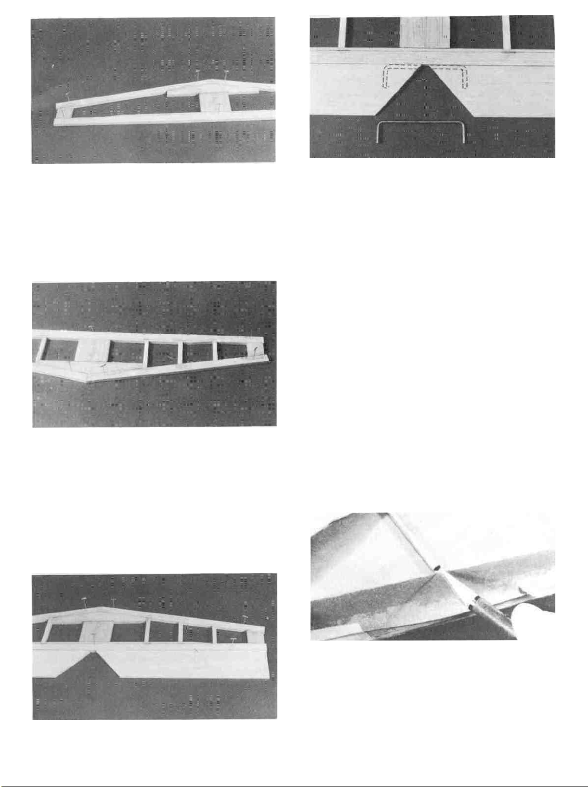
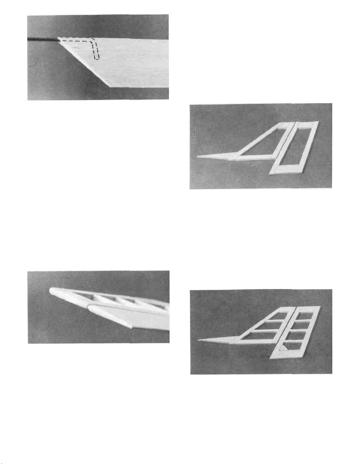
D 5. Pin the leading and trailing edges in place and
glue everything together with thin CA
D 6. Cut the "ribs" from the 1/4" square x 30" stick
(FUN 1 S02) and glue them in place. Remove the stab from
the work surface and apply med/thick CA to all of the
joints. Sand both sides of the stab smooth and replace the
stab on the plan.
D 8. Lay the 1/8" wire elevator joiner (WBNT145)
in place on the elevators and mark its outline using a fine
point fell-tip pen. Be sure to position the joiner wire
directly over where it is shown on the plans which gives
you about 1/32" clearance between the front of the wire
and the trailing edge of the stab.
D 9. Remove the elevators from the plan and draw a
centerline along the leading edge of each. Accurately drill
holes in the elevators for the 1/8" wire joiner. Begin by
drilling a 1/16" or 5/64" pilot hole, then drill the final hole
to a depth of 7/8" with a 9/64" drill bit. (The hole is drilled
slightly oversize to allow for positioning, and to create a
hard epoxy "sleeve" around the wire).
D 7. Cut the two elevators from the Tapered Elevator
Strip (FUN1S05) and pin or tape them in place behind the
stab.
D 10. Using an Xacto knife, sharpen the inside of one
end of a 1/8" diameter brass tube and use it to cut grooves
in the leading edge of the elevators to accept the joiner
wire.
D 11. Roughen the joiner wire with coarse sandpaper,
then clean the wire thoroughly with alcohol to remove any
oily residue.
Page 8
D 12. Trial fit the joiner wire into the elevators, then
glue it in using 5-minute epoxy. Work plenty of epoxy into
the holes with a toothpick, then pin the elevators in place
over the plan to insure perfect alignment. Keep the joiner
pushed into the elevators all the way to keep a 1/32" gap
between the front of the joiner and the slab trailing edge.
Keep this assembly pinned down until the glue has com-
pletely cured.
D 13. Remove the stab from the work surface and sand
the tips of the leading and trailing edge flush with the stab
ends. Draw a centerline around the stab and sand the
leading edge and the tips of the slab to a nice rounded cross
section.
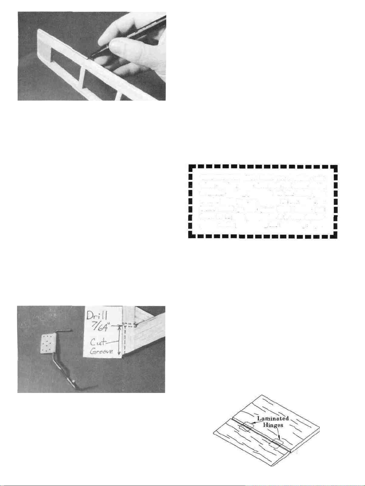
U 2. Cut the fin and rudder frame from the 1/4" x
1/2" and the 1/4" x 1" slicks and pin them in place over the
plan. Put a drop of thin CA on each joint but be careful not
to glue the fin to the rudder.
D 3. Cut the dorsal fin from the l/4"xl" slick and tack
glue it to the fin using the plan to correctly position it. The
dorsal fin may have to be removed later. Cut the rudder
gusset from the same stick and glue it in place.
D 14. Remove the elevators from the plan and sand the
leading edge to a V-shape as shown on the plans. Tape the
elevators in place against the slab and sand the elevator
ends to match the stab.
BUILD THE FIN AND RUDDER
D 1. Tape the fuselage plan down to your flat work
surface. Tape a piece of waxed paper over the fin and
rudder portion of the plan.
D 4. Cut the "ribs" from the 1/4" square stick and glue
them in place with CA.
D 5. Remove the fin and rudder from the work surface
and apply med/thick CA to all joints. Use a T-bar or
sanding block to sand both sides smooth.
8
Page 9
I—I 6. Carefully draw a centerline all around the edges
of the fin and rudder (this will help to maintain symmetry
when sanding).
1—1 7. Using a sanding block and coarse (50 or 80-grit)
sandpaper, sand both sides of the rudder to a taper as
shown on the plans. The trailing edge should end up
approximately 3/32" wide and have a rounded shape. (Do
not sand to a sharp edge). Sand the bottom edge to a
rounded shape. Sand the leading edge to a "V-shape" as
shown on the plan. Sand the lop and front edges of the fin
and dorsal fin to a rounded shape but leave the trailing
edge square.
TEMPORARILY INSTALL HINGES
(Do not glue)
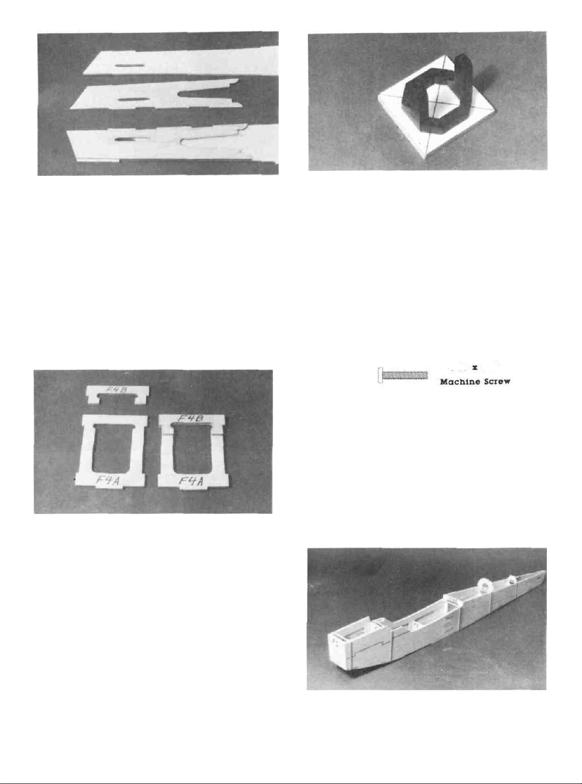
NOTE: On an experimental basis, we have included
"laminated hinges" in this kit, and the following instructions are written for this type of hinge. Our R&D department has thoroughly tested these hinges and found them to
be easy to install and sufficiently strong and durable for
this type of airplane. However, as the kit builder you are
reminded that you are ultimately responsible for the structural integrity of your aircraft. If you are not confident
using this type of hinge, please feel free to substitute your
favorite hinge.
I_I 1. Lay the rudder and elevators on the plan and mark
the hinge locations. Place the rudder against the fin TE
and transfer the marks over to the fin. Place the elevators
against the slab TE and transfer the marks over to the slab.
CAUTION!!!: You must use extreme care
when cutting hinge slots with an Xacto knife,
to avoid cutting yourself! If the balsa part
breaks while you are pushing on the knife, the
blade could go into your hand before you
know it! A good precaution is to wear leather
gloves while performing the following steps.
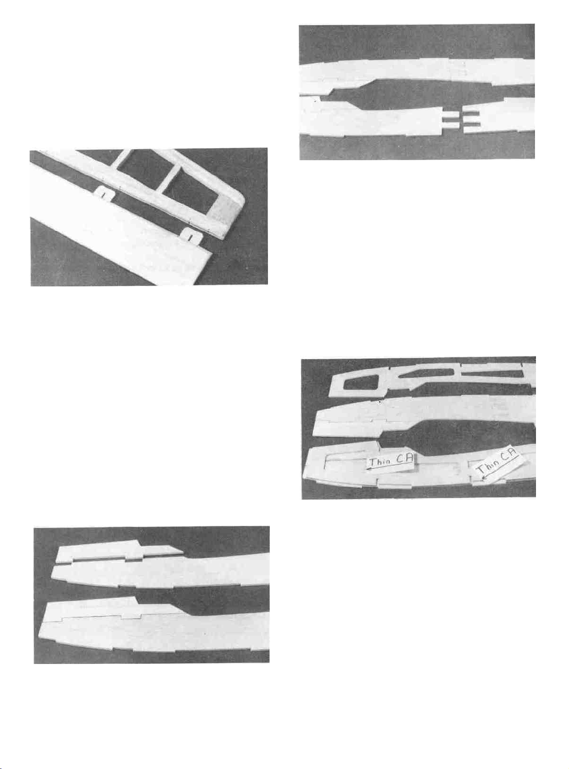
I_I 8. If you arc building a taildragger- check the plans
and mark the location of the tailgear (WBNT128) on the
rudder. Drill a 7/64" hole in the rudder (the hole is drilled
slightly oversize to allow for positioning, and to create a
hard epoxy "sleeve" around the wire). Then groove the
rudder leading edge to accept the tail-gear wire using the
sharpened 1/8" brass tube from earlier. (Sec the photo at
step 10 on page 7).
D 2. Cut the hinge slots on the accurate centerlines
which you previously drew, using an Xacto knife. The
recommended procedure for cutting hinge slots with an
Xacto knife is given below.
A. Begin by carefully cutting a very shallow
slit in the trailing edge at the hinge location. This first
cut is to establish your cut in the right place, so concentrate on staying on the centerline and don't cut
too deep!
B. Make three or four more cuts in the same
line, going slightly deeper each time. As you make
these additional cuts, work on going straight into the
wood. Continue this process while "wiggling" the
knife handle back and forth until the blade has reached
the proper depth for the hinge.
9
Page 10
D C. Trial fit the hinge into the slot. If the hinge is
difficult to push in, re-insert the knife and move it back and
forth in the slot a few limes to enlarge the slot.
D 3. Insert the hinges into the slots and trial fit the
rudder and elevators in place on the fin and stab. Do not
glue the hinges until you are instructed to do so later in
this book. Hinge gluing instructions are included later.
D 2. Position one of the 1/8" die-cut balsa rear fuse
sides (FUN1F02) behind the front fuse side you just
assembled. Slide the two
against the work surface. Line the two parts up over the
plan and apply thin CA along the joint. Sand both sides of
the balsa fuse side smooth.
parts
together pressing them
Hard
FUSELAGE
CONSTRUCTION
PREPARE FUSE SIDE
NOTE: The photos show both fuse sides being assembled at the same time to help you identify the parts.
You should assemble one side first as the instructions
explain.
D 1. Position one of the 1/8" die-cut balsa upper
front fuse sides (FUN1F03) above one of the 1/8" die-
cut lower front fuse sides (FUN1F01). Slide the two
parts together pressing them flat against the work surface
and apply thin CA along the joint.
D 3. Lay one of the 1/8" die-cut plywood front fuse
doublers (FUN1F06) on lop of the balsa fuse side. The
doubler should line up with the fuse side at the front 1/2"
of the doubler, the rear 3-1/2" of the doubler and around
the wing saddle area. Study the plan and photo carefully
to make sure you correctly position the doubler. When
you have it in position apply thin CA around all edges of
the doubler, including the inside lightening holes.
D 4. Glue one of the 3/32" balsa die-cut rear fuse
doublers
back edge of the fuselage and the top and bottom of the
fuse side. Use thin CA to glue it in place. (The photo for
this step is at the top of the next page).
10
(FUN1F05)
to the
fuse
side
lining
it
up
with
the
Page 11
D 5. Go back to step 1 and assemble the other fuselage
side. BE CAREFUL TO ASSEMBLE A RIGHT AND
A LEFT FUSE SIDE. DO NOT MAKE TWO EXACTLY ALIKE!!!
holes. This will automatically center it. Hold it in place
and use a nail to make a mark in the center of each hole.
D 2. Remove the engine mount and drill 9/64" holes at
the bolt locations, then install the 4-40 blind nuts (NUTS001)
on the BACK of Fl. Press the blind nuts in with pliers, or
tap them in with a hammer.
D 3. Temporarily attach the engine mount to the fire-
wall with the 4-40 x 5/8" bolts (SCRW052). Use the bolts
to help pull the blind nuts into place. If you are using a
different mount and more than 1/8" of the bolt protrudes
through the firewall, you should cut off the excess bolt length.
4.40 x 5/8"
ASSEMBLE THE FUSELAGE
D 1 Lay the two fuselage sides down flat on the work
surface with the doublers facing up. Trial fit formers Fl,
F2A, F3, F4A/B, F5 and F6 (from FUN1FO8 AND
FUN 1 F09) in place on both fuse sides.
D 6. Glue former F4B (FUN1F09) on former F4A
(FUN1 F08) lining up the edges as shown in the photo.
PREPARE THE FIREWALL (Fl)
D 1. Use a straight edge to draw two crossing lines
from corner to corner on the FRONT face of former Fl
(FUN1 F20). Refer to the fuse side view on the plans to
determine the front of the firewall. Position the engine
mount (MM 19D90) against former Fl so that the crossing
lines arc visible through each of the four engine mount
D 2. Using #64 rubberbands to hold everything to-
gether, assemble the fuse sides along with the formers and
the 1/8" die-cut balsa rear fuse bottom (FUNF04)) and
the 1/8" die-cut plywood front fuse bottom (FUN 1 F09).
11
Page 12
Make sure everything is seated properly and apply thin CA
to all of the joints starling at former Fl and working your
way to the rear. At the rear of the fuse glue the two sides
together. Do one former/section at a time and hold
everything lightly together while the glue cures. This
structure is self-aligning and can be done right in your lap,
it docs not need to be done on a flat surface. Apply med/
thick CA to all the joints.
D 3. Glue the 1/4" x 2" x 2-5/8" plywood landing
gear
plate
(FLJN1F13)
in
place
with
med/thick
CA or
epoxy. It goes in the forward position behind former F2
for taildraggcrs and in the rear position behind former F3
for tricycle gear. OPTIONAL: If you want to you can cut
an extra landing gear plate and glue one in each position
and so you can switch from one style of landing gear to the
other.
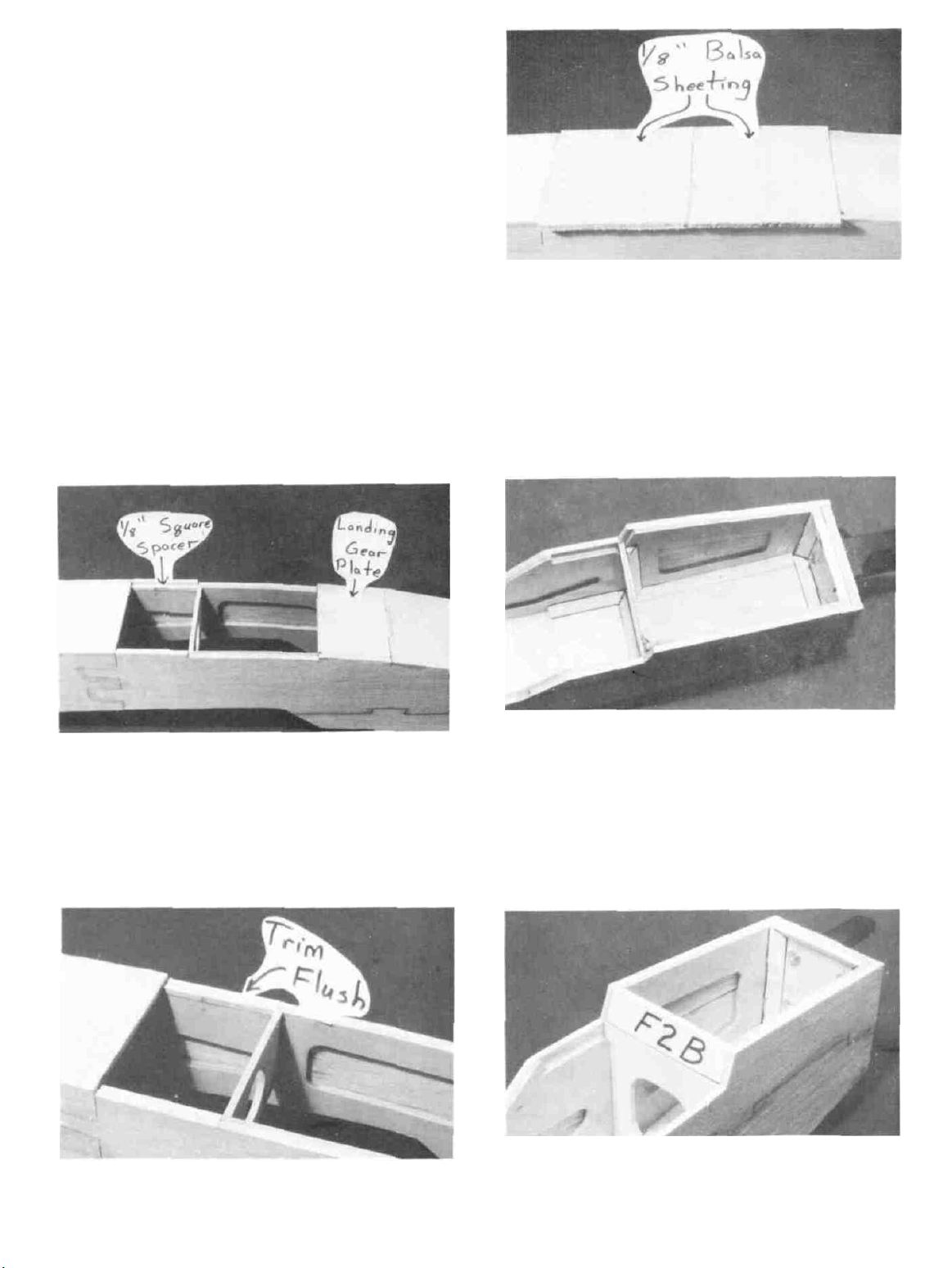
D 6. Cut the 1/8" x 3" x 6-1/2" middle bottom sheet
(FUN1F22) of balsa exactly in half to make two 3-1/4"
pieces and glue them in place on the bottom of the fuse.
Note: The grain should run ACROSS the fuselage. Sand
the edges of the sheeting flush with the fuse sides.
D 4. Cut the 1/8" x 1/8" x 4" balsa spacer (FUN 1F21)
exactly in half to get two 2" pieces. Glue these pieces into
the other landing gear cutout.
D 5. Trim the fuselage sides flush with the spacers you
just glued in.
D 7. Cut pieces of the 1/4" x 30" balsa triangle
(BAL143) to the correct length and glue them in place
around the firewall, along the front fuse bottom, along the
front of F2A and above the landing gear plate. The plans
and the photos help show where ihe triangle goes.
D 8. Glue former F2B (FUN1F09) in place on top of
former F2A. Sand the lop of the former flush with the top
edge of the fuselage.
12
Page 13

D 9. Using epoxy securely glue the 1/4" plywood
wing bolt block (FUN1F18) in place. Notice that the
block is cut square and there is a slight gap towards the
rear. Simply press the fuselage sides up tight against the
wing bolt block until the glue cures. Add three pieces of
1/4" triangle underneath the block as shown in the pholo.
D 10. Install the outer pushrod tubes (PLTB011) by
threading them through formers F5 and F6 and then
through the OPPOSITE fuse side. Make sure the one that
goes through (the highest hole in F6 is above the other
where they cross. Allow them to extend about 1" past F4B
and 1" past the die-cut fuselage exit. Mark where the tubes
contact the formers and remove the tubes. Scuff up the
tube surface with 100 grit sandpaper in those locations and
replace in the fuselage. Glue the tubes in place with med/
thick CA.
D 12. If you want to install an antenna tube in the
fuselage, now is the time to do that. We normally use a
piece of pushrod tubing and secure it along the fuselage
bottom, exiting near (the rear of the fuselage. Be sure to
anchor the tube securely as (the maneuvers this plane is
capable of could knock it loose).
D 11. Cut the tubes off flush with the fuselage side and
apply some balsa filler around the tube. After the filler
dries sand everything flush with the fuselage side. (See
photo for this step in next column)
D 13. Securely glue the 3/32" die-cut stab bed
(FUN 1 F07) in place with CA. The embossed line on the
stab bed should be facing up. Make sure it is sealed properly so the slab will sit level without modification.
13
Page 14

D 14. Center former F4T (FUN 1F08) on top of former
F4A/B. The back of F4T should be lined up with the back
of F4B and it should be tilted back until the top of F4T is
4-5/8" from F5. When positioned correctly glue it in place
with med/thick CA.
D 15. Notice an embossed line across the slab bed
3-7/8" from the rear. This is where the front of the stab will
be. If it is hard to see draw a line there.
D 17. Locate the 1/16" x 2-5/8" x 16" turtle deck
sheeting (FUN1F16) and cut it in two as shown in the
sketch below.
Cut here
1/4"
2-3/8"
Turtle Deck Sheeting
D 16. Glue three 1/8" x 3/16" x 18" balsa stringers
(FUN1 F14) in place as shown in the photo. The bottom
stringer should start at the line you just drew on the stab
bed and remain 1/16" away from the edge of the fuselage
side to allow for the turtle deck sheeting which will be
applied later. The top stringer should be attached to the
bottom stinger near the stab bed but not be touching the
stab bed as shown in the photo. The middle stringer should
start at former F6. Cut the excess stringers off flush with
former F4T. Do the same for the other side of the turtle
deck.
D 18. Glue the sheeting onto the little ledge formed by
the fuselage side and the bottom stringer.
D 19. Use a damp rag to wet the outside of the turtle
deck sheeting to make it bend easier. Apply some med/
thick CA to formers F4T, F5 and F6 and bend the sheeting
into place. Use at least four strips of masking tape to hold
the sheeting. Apply thin CA along the stringers and allow
the glue to cure. Glue the other piece of sheeting in place.
14
Page 15

D 20. Cut the sheeting off flush with former F4T and the
end of the stringers and use a sanding block to sand the top
of the sheeting flush with the top of the formers and
stringers. Be careful not sand any dips or valleys into it
or the top will not fit nicely.
D 23. Glue the 3/32" die-cut turtle deck face (FUN 1 F07)
in place on the front of F4T and sand it flush using a
sanding block pressed flat against the turtle deck. Do not
round off the corners of the face because the canopy will
bull up against this piece. Also sand it flush with the face
of F4B.
D 21. Glue the 3/16" x 1-3/8" x 14-7/8" balsa turtle
deck top (FUN 1 Fl 5) in place making sure it is centered.
Cut off the ends and sand them flush with former F4T and
the end of the stringers.
D 22. Use a razor plane to carefully "rough" carve the
turtle deck top and then sand it with a sanding block to
blend in with the sheeting.
D 24. Glue the 3/16" x 15/16" x 3" balsa hatch front
(FUN1F11) in place. Allow it to overlap former Fl
slightly (1/32" or less). Sand it flush with the fuse sides
and the front of Fl.
D 25. Glue the 1/4" square x 2-5/8" basswood hatch
hold down block (FUN 1 Fl 7) to the front of former F2B.
Notice that the top of the hold down is slanted and not
flush with the top of the fuse sides.
15
Page 16

D 26. Glue the 1/16" x 1" x 1" plywood hatch tongue
(FUN1F12) to the front of the hatch (FUN1F10) so that
half of the tongue extends past the edge of the hatch.
to round off the back edge of the hatch because the wing
fairing will bull up against this surface.
#2 x 3/8"
Sheet Metal Screw
#4 Flat Washer
WING ASSEMBLY
NOTE: The following instructions explain how to build
the wing on a flat surface using the built in "Jig Tabs",
directly on the plans.
D 27. Position the hatch on the fuselage and use a piece
of masking tape to hold it against the hatch front and act
like a hinge. Push a T-pin through the hatch approximately
3/8" from the edge of the fuselage and 1/16" in front of
F2B. Pick the hatch up slightly and look see where the
pin stuck into the basswood hold down. It should enter the
basswood as close to the former as possible (within 1/32").
If it does not, adjust the position of the pin and try it again.
Do this on both sides of the hatch and then drill a 1/16" hole
where each pin is.
D 28. Remove the hatch and enlarge the holes in the
hatch only 3/32".
D 29. Use two #2 x 3/8" sheet metal screws (SCRW024)
and two #4 washers (WSHR005) to screw the hatch into
place. Sand the sides and back of the hatch flush with the
fuselage sides and the face of former F2B. Be careful not
BUILD THE WING PANELS
NOTE: It will be helpful to build the wing on a piece of
"Celotex"
which you may easily slick pins firmly hold down the
wing parts while building, avoid warps. *Available
from lumber companies and home centers.
D
1.
the wing drawing with waxed paper (so you won't glue the
wing the plan!). NOTE: If your work space is limited,
you may cut the left and right wing half drawings apart.
D 2. The shaped wing leading edges (LE) (FUN 1W07)
and trailing edges (TE) (FUN1W08) are fastened together by thin strips of balsa. Separate them by cutting
between the two pieces. Sand away the excess balsa that
remains along the edges after cutting them apart, using a
T-bar with 100-grit sandpaper.
D 3. Before using the 1/4" x 3/8" x 28" hard balsa
spars (FUN1W09), examine them carefully for possible
imperfections. Look for knots, soft spots, diagonal grain
16
or
Tape
other
semi-soft (and
the plan
to
your
flat
flat)
work
surface, into
surface,
and
cover
Page 17

and any other imperfections. If possible, position each
spar so the imperfections (if any) are on the outer half of
the wing panel (toward the tip), where they will be least
affected by high stress. If the spars arc warped slightly, try
to "balance them out" by installing the warped spars in
opposite directions (see sketch). NOTICE: If you feel
that any of the wing parts arc unusable due to severe warps
or other defects, give us a call and we'll replace the parts.
TWO WARPED SPARS INSTALLED
THIS WAY WILL RESULT IN A
STRAIGHT WING
NOTE:
LEFT
the RIGHT wing panel.
wing
Follow
panel,
steps 6 through
then
repeat
13
to
these steps
build
to
build
the
TWO WARPED SPARS INSTALLED
THIS WAY WILL RESULT IN A
WARPED WING
D 4. Find ihe four 1/8" x 3/8" x 14" balsa spar
doublers
(FUN 1 W
17).
Sand
the
last 2" one end
of
each
spar doubler to a taper as shown in the photo. Glue the spar
doublers to the spars with the square end of the spar
doubler lined up with the spar end. Sand the doubler to
match the spar and to remove any excess glue.
Work
Surface
D D 6. Use some scrap pieces of 1/16" balsa to shim the
spar up off the work surface 1/16". Place a "shim" in every
other rib bay and pin a spar to the plan with the spar
doubler up and toward the root. NOTE: The spars are
cut slightly too long. Position the spar on the plan so approximately 1/8" extends past the center of the wing plan.
D D 7. Place the ribs on the spar with the jig tabs down,
in their approximate position, but do not glue. NOTE:
The wing is built upside down.
D 5. Carefully punch out all the die-cut 3/32" balsa
wing ribs. Sand the edges slightly to remove any diecutting irregularities. If you are going to build the wing on
a wing jig do not punch out the lightning holes yet as some
of them contain the jig holes. You may even have to tack
glue these in place until the wing is removed from the jig.
If you arc going to install individual servos for each
aileron, cut out me servo rail notches in ribs W4 and W5.
D D 8. Examine the shaped, notched balsa trailing
edges. Notice that the notches at one end of each TE arc
closer together. This is the "root" end of me TE. Insert all
ribs into the TE notches. The TE should rest on the ledges
on ribs W3, W6 and W 10 but make sure that it is also flush
with the tops of all ribs. Check to make sure that each rib
is perpendicular to the work surface and apply a drop of
thin CA to each joint on the TE and the spar.
NOTE: If you are going to use only one servo now but
think you may want to have individual servos later, go
ahead and build the servo rails into the wing and cover
over them. Then they will be there if you decide you want
them. 17
NOTE: Thin CA glue may be used in tight-fitting joints,
but to insure strong joints we recommend that you follow
up by also applying medium or med/thick CA to all joints.
17
Page 18

D D 9. (Glue the top spar in place with the spar doubler
facing down.
properly in the jig labs and it is centered "UP and DOWN"
on the ribs. It may be necessary to remove a small amount
of material from the jig labs for the LE to fit properly.
IMPORTANT:
necessary to remove some of the pins holding the wing
down to your building board. As you do, take other steps
as necessary to continue holding the wing down, such as
by applying weight lo the top of the wing, or by relocating
the pins.
D D 10. Position the 3/32" x 3" x 14-7/8" balsa shear
web sheet (FUN1W14) over the shear web template on
the plan. Make sure the sheet is correctly aligned with the
template and transfer the marks from the plan to the sheet.
Move the sheet over to the side and write each web
designation onto the
one goes. Use a straight edge and an Xacto knife to cut
between the lines making the shear webs.
Glue
the
LE in place making
In
the
following
sheet
so
you
sure
it
steps
you'll
will
know where each
is
resting
find
it
NOTE: There will be a small gap between the ribs and the
webs but this is normal.
D D 12. With the wing accurately lined up over the
plan, cut the leading edge. trailing edge and the spars off
at the root end. Use a drafting triangle or square to accurately transfer the cutoff lines from the plan to the structure.
D D 13. Cut the LE. TE and Spars off flush with rib
W10. If you built the wing on a wing jig, now is the time
to remove the panel from the jig.
D 14. Go back to step 6 and assemble the other wing
panel.
JOIN THE WING PANELS
D 1. On a flat surface trial fit the two wing halves
together. The leading edges, trailing edges and the spars
should bull up nicely against each other. Sight down the
trailing edges to make sure they are straight with each
other (No sweep in the wing). Sand where needed to
achieve a good straight fit between the wings. NOTE: The
dihedral is automatically built into the wing by building it
flat upside down on the building board. This makes the lop
spars
level
with
each other and the bottom
slightly with the taper of the wing.
spars
will
rise
D D 11. Securely glue the webs to the back side of the
spars. Center the webs between the spars and the ribs.
D 2. Use med/thick CA to "tack glue the two panels
together and pin or hold everything in place while the glue
18
Page 19

cures. Make sure the spars are precisely lined up with
each other.
D 3. Trial fit the 1/8" plywood wing joiner (FUN 1 Wl 3)
in place between the spars. It should fit between the spars
without protruding past the edges of the spars. Sand it if
needed to achieve a good fit without pushing the spars
apart. Securely glue it in place with epoxy but be careful
not to get any glue on the front or back of the spars.
trail ing edges. The top of the dowel aligner should he flush
with the top of the trailing edges. Sand or file a round
notch in each trailing edge where the dowel aligner notches
are as shown in the photo.
D 4. Trial fit the 1/32" plywood dihedral braces
(FUN1W06) in place. They easily should fit between the
ribs and should not extend past the outer edges of the spars.
Hold
or clamp them
them in place with epoxy.
D 5. Glue the 1/8" plywood die-cut dowel aligner
(FUN1FOS) to the back of the trailing edge (If you are
going to use one aileron servo just tack glue the aligner
in place as it will be removed later). Position it so the
embossed line is centered with me joint between the two
tightly
against
the
spar
while
gluing
D 6. Glue two 1/8" die-cut balsa W1C ribs
(FLIN1W02) together making sure they are lined up with
each other.
D 7. Gl ue a 1/8" ply die-cut W 1 B rib (FUN1 WO 1) to
one side of the W 1 C ribs and glue a 1/8" ply die-cut W ID
rib (FUN 1 W01) to the other side of the W 1 C ribs. Line
these ribs up so that all of their trailing edges are even and
sand off the extra balsa around the dowel hole flush with
19
Page 20

the plywood ribs. NOTE: when making this rib assembly
for the other wing, be sure to glue the plywood ribs to the
opposite sides of the W 1 C ribs so you will have a "right"
and a "left" as the photo above shows.
D 8. Round off both ends of each 1/4" x 5-3/4" dowel
(DOWEL037) and trial fit them into the Wl rib assemblies. Glue the dowels in place with plenty of med/thick
CA or epoxy.
D 11. Glue the two 1/8" ply W1A ribs (FUN1W01)
together and glue them in place in the center of the wing as
shown in the photo. Glue a piece of 1/4" triangle on both
sides of the ribs near the spars.
D 12. Glue the 1/8" balsa W2B ribs (FUN1W02) in
place in the remaining notches. Be sure the 1/2" diameter
hole is down.
D 13. Remove the wing from the work surface and test
fit it to the fuselage. Sand a "Flat" on the front of the
leading edge to allow it to seal properly. The bottom of the
leading edge
way in the saddle but we can make sure the wing is aligned.
will
still
keep
the
wing
from
seating
all
the
D 9. Position the wing back over the plan and trial fit
both Wl rib assemblies. Enlarge the notches in the TE if
needed to get the dowels to be positioned exactly over the
notches in the dowel aligner. Tack glue the rib assemblies
at the trailing edge so they are centered up and down on the
trailing edge. Don't worry if the dowels are not seated in
the aligner notches but do make sure they are both directly
above the aligner notches. Securely glue the front of the
rib assemblies to the dihedral brace. Add some med/thick
CA to the trailing edge joint but don't allow excess glue to
accumulate on the trailing edge or the 1/16" sheeting will
not fit well.
D 10. Add a piece of 1/4" triangle (BAL143) to each
outside spar/Wl rib joint and a small piece at the trailing
edge of each rib assembly (See photo at step 11).
D 14. Tie a 3' piece of string to a T-pin and stick the T-
pin into the middle of the slab base at the very back. Pull
the string out to one wing tip and mark it or grip it with your
fingers where it touches the tip. Swing the string over to
the other tip to see if the two distances are equal. If they
are, make a mark on the leading edge and former F2B so
you will know when the wing is on correctly. If the
distance is not equal, adjust the wing until it is, then make
the mark.
Both distances must
be equal!
20
Page 21

D 15. Glue the 1/8" plywood W2A's (FLJN1W01) to
the 1/8" balsa W2C ribs (FUN 1W02). Make a RIGHT
and a LEFT!
D 16. Measure to find the middle of the 1/4" plywood
wing bolt plate (FUN1 Wl 5) and make a mark at the front
edge. Tack glue it in place on the two Wl A ribs with the
mark in the middle of the two ribs and pushed up against
the leading edge and level.
D 20. When satisfied with the wing alignment the front
pieces must be securely glued in place. Add med/thick
CA to all joints that have only been tack-glucd. Add pieces
of 1/4" tri around the wing bolt plate and the W2 rib assem-
blies.
D 17. Tack glue the W2 front rib assemblies in place
making sure they are centered up and down on the leading
edge and spars and pressed against the ends of the wing
bolt plate.
D 18. On the side of the wing with the dowels sticking
out (the bottom of the wing) the leading edge should be cut
away flush with the wing bolt plate between the W2 front
ribs (See bottom photo at step 20).
D 19. Replace the wing on the fuselage and recheck its
alignment. Also set the fuselage flat on the work surface
and make sure the wing is parallel to the surface. If it is not,
adjust the wing bolt plate or the dowel notches in former
F4 until they are.
D 21. Replace the wing on the fuselage with the align-
ment marks lined up and hold the wing tightly to the
fuselage. Drill two 13/64" holes through the wing bolt
plate and down through the wing boll block as shown
above. The holes should be approximately centered in the
open part of the plate. Keep the drill perpendicular to
the wing bolt plate while doing this and do not allow the
wing to move while drilling.
D 22. Remove the wing and re-drill me holes in the
wing only to 1/4".
21
Page 22

SHEET THE WINGS
NOTE: In the next steps, maintain straightness by
keeping the wing down on the flat surface.
D 1. Before applying the leading edge sheeting in the
next step, use yourT-bar to lightly sand off any protruding
edges on the shear webs and smoothly blend the ribs to the
spars.
2-15/16"
D 23. Use a 1/4-20 tap and a tap wrench to cut threads
in the ply wing bolt block in the fuselage.
D 24. Harden the threads in the wing bolt block by
applying thin CA to the threads. After the glue has com-
pletely cured, re-tap the threads.
D 25. Cut the 1/4-20 x 2" nylon wing bolts (NY-
LON 13) so the threaded portion is approximately 3/4"
long. An easy way to cleanly cut them without messing up
the threads is to press an Xacto knife into the bolt where
you want to cut it and then bend the bolt with your hands.
It will break where the cut is, just clean up the threads with
the knife.
1/4-20 x 2" Nylon Bolt
28"
2-1/8-
Leading Edge Sheeting
D 2. Cut the 1/16" balsa leading edge sheeting
(FUN 1 W 11) as shown in the sketch above (Make 4).
D 3. Prepare the balsa leading edge sheeting by sand-
ing the front edge to a slight bevel so it will fit snugly
against the back of the leading edge
Bevel this edge
D 26. Test fit the wing to the fuse using the 1/4-20 nylon
bolts and then remove the wing.
D 27. Later you will apply foam wing seating tape or
silcone sealer to the wing saddle. To allow space for this
wing cushion material, you may sand the saddle slightly in
the areas where the wing touches the saddle, to provide a
small gap.
D 4. Position the leading edge sheeting in place and
glue it to the leading edge with thin CA. Do not attempt to
glue it to the ribs yet, just let it rest on the ribs while you
glue it to the LE. NOTE: The root end of the sheet should
start at the wing centerline.
D 5. Check the leading edge sheeting. If it does not
bend around the ribs easily, wet the top surface of the
sheeting and wail a few minutes so it will bend easier.
D 6. Apply med/thick CA glue to the top edge of the
ribs and to the top of the spar. Bend the sheeting down onto
the ribs and spar. Place one of the ailerons on top of the
sheeting with the thick edge near the spar and apply hand
22
Page 23

D 10. Install the top 1/16" wing sheeting using the same
procedure.
D 11. Cut a hole in the lop sheeting above each wing
bolt hole big enough to get the wing bolts in and out.
INSTALL AILERON SERVOS
pressure to hold the sheeting down until the glue has set.
D 7. Trim the root end of the sheeting even with the
center of the wing over the spar, and flush with rib W3 in
front of the spar. Trim and sand the sheeting at the tip of
the wing flush with rib W10.
IF YOU ARE GOING TO INSTALL TWO
AILERON SERVOS SKIP
AHEAD TO STEP 3.
D 1. Cut two 1/4" x 3/8" x 3-1/4" basswood aileron
servo rails (FUN1W16) to fit between the Wl rib assem-
blies (approx. 1-1/4" long). Use a servo to determine the
positioning of the rails and tack glue them in place in the
bottom of the notches with med/thick CA. Try to keep the
servo as low in the wing as possible. Be sure to allow
enough space between the rails to get the servo in and out.
Add more glue to securely hold the rails in place.
D 8. Install the other panel wing sheeting.
D 9. Cut the jig tabs off of each rib using the embossed
line as a guide and sand the ribs smooth.
D 2. Position the servo in place on the rails and mark
through the mounting holes where to drill. Remove the
servo and use a 1 /16" drill bit to drill holes where you made
the marks.
IF YOU ARE ONLY INSTALLING ONE
AILERON SERVO SKIP AHEAD TO
ADD THE CENTER SHEET.
D 3. If you arc installing two aileron (flaperon) servos
test fit the two 1/4" x 3/8" x 3-1/4" basswood aileron
servo rails (FUN1W16) in place in the bottom of the
notches in ribs W4 and W5. Check the fit of the aileron
servo between these rails and adjust if necessary. Se-
curely glue the rails in place with med/thick CA.
23
Page 24

D 4. Position the servo in the center of the rib bay and
mark on the rails, through the mounting holes, where to
drill. Remove the servo and use a 1/16" drill bit to drill
holes where you made the marks.
D 5. Install the servos using the mounting screws
provided with your radio.
D 6. Cut four pieces of 1/4" square balsa (FUN 1S02)
approximately 1/8" longer than the servo and glue one on
each side of each servo. Cut four more pieces of 1/4"
square balsa to fit across the ends of the "servo bays" and
glue them to the 1/4" balsa already in place. Sand these
"frames" so they are flush with the surface of the ribs but
do not change the shape of the ribs while sanding.
NOTE: Put a strip of masking tape on each rib to keep
from sanding the ribs during this step.
end flush with rib Wl B. Any extra tube protruding more
than 1/4" past Rib W4 can be cut off. Glue the tube into
place with med/thick CA.
ADD THE CENTER SHEETING
D 1. Cut two of the 1/16" x 2-5/8" x 9-7/8" balsa wing
center sheets (FUN1W12) to fit between the W3 ribs.
Position one of the sheets between the ribs and mark where
the center of the leading edge sheet is. Now slide the sheet
forward until it touches the rear of the leading edge
sheeting joint and mark where the sheets cross at the W3
ribs. Remove the center sheet and cut from the center dot
to each end dot. Test fit the sheeting back into place. Sand
it if needed and glue it in place. Repeat this for the other
side of the wing.
D 7. Enlarge (elongate) the hole in rib W4 towards the
TE so that you can install the paper tube (PTUBE001) for
carrying the servo cable. The paper tube can be held
diagonally through rib W3, inserted into rib W4, and then
slid through the remaining ribs and into position with its
D 2. Cut four pieces of sheeting 3-1/2" long from the
remaining 1/16" x 2-5/8" x 9-7/8" center sheets. Glue one
of these sheets behind the one you just installed with it
centered over the Wl and W2 ribs. Cut another one to fit
between the last one and the trailing edge and glue it in
place. Do the same for the other side of the wing. On the
bottom of the wing the last sheet will have to be cut similar
to the sketch on the following page to clear the dowels.
24
Page 25

Cut out for dowels
D 3. Cut the front center sheet at an angle to match up
with the rear pieces as shown in the photo. Also cut away
the sheeting on the bottom of the wing for either the servo
cables or the aileron servo whichever the case may be.
that they follow the natural contour of the wing and are
not tilted up or down. Sand them to fair smoothly with
the TE and sand the ends flush with rib W10.
D
6.
Tack
in place with two drops of med. CA. They should line up
with the front portion of the airfoil and be centered with the
3" aileron portion at the TE. Sand the wing and wing tip
to get a smooth transition between the two. Remove the
wing tip and sand both sides smooth and lightly sand the
edges to remove any "fuzz". They will be glued back on
after the plane is covered.
glue
the 1/8"
plywood
Wing
Tips
(FUN1W01)
D 4. Sand the leading edge so it will blend in smoothly
with the leading edge sheeting.
IMPORTANT: The shape of the leading edge will
affect the way this airplane performs snap rolls and
spins. A blunt, rounded leading edge will "soften"
the stall, making the plane very docile when flying
slowly, enabling it to flare nose-high for very slow
landings; however, this may cause the plane to be a
little sluggish when trying to enter a snap roll or spin.
A sharper leading edge will help the plane enter snap
roll and spin maneuvers more crisply, while sacrificing only a little of the low speed stability. The
leading edge has been approximately pre-shaped,
and will work great for most sport flying. If you
would like crisper snap rolls and spins you should
sand the inner 1/3 of each wing panel to gradually
form a slightly sharper LE radius. To avoid tip
stalls, make sure the leading edges of both wing
panels have the same shape.
D 5. Cut 3" off each aileron (FUN 110) and glue the
short pieces to the tip end of each trailing edge. Make sure
INSTALL AILERON TORQUE RODS
(One aileron servo only)
D 1. Remove the dowel aligner which was tack glued
into place.
D 2. Cut a groove to fit the torque rods in the TE. A
clearance groove also has to be cut in the top of the TE to
allow the torque rods to move. Also cut small clearance
notches in the dowel aligner. Note: The torque rod
horns must exit the BOTTOM of the wing! Test fit the
torque rods in the groove, they should be totally in the TE
so the dowel aligner will fit back into place.
25
Page 26

D 3. Roughen the unthreaded end of the aileron torque
rods (WBNT153) with 100-grt sandpaper, and file the
same end to a wedge shape.
FILE END TO
WEDGE SHAPE
D 4. Roughen the surface of the plastic bearing tubes
with 100-grt sandpaper.
D 5. Clean the torque rods and bearing tubes with
alcohol.
D 6. Slide the plastic bearings toward the threaded end
of the torque rods, then use a toothpick to apply a small
amount of petroleum jelly to the ends of the plastic tubes
(to help prevent glue from getting inside and locking up
the torque rods).
D 1. Draw an accurate centerline along the LE of the
tapered balsa ailerons and the wing TE.
D 2. Make a mark 1/8" outboard of the dowel aligner
and cut the ailerons to fit between this mark and the tip of
the wing. You should provide approximately 1/16" gap at
the outboard end of the ailerons.
IF YOU ARE INSTALLING 2 SERVOS
SKIP
TO STEP 5!
D 3. Lay the ailerons in place, with the torque rods
resting on top of the ailerons. Mark the torque rod
locations on the top of the ailerons (Similar to the
procedure used in step 5 on page 9).
D 7. Use 5-minutc epoxy or med/thick CA sparingly
to glue the plastic bearing lubes into the grooves in the TE
and the dowel aligner back into place. Wipe off any excess
glue and allow it to harden.
INSTALL AILERONS
NOTE: Do not glue the aileron hinges until after your
model has been covered.
D 4. Drill a 7/64" hole in the ailerons at the torque rod
locations, starting at the leading edge centerline and drilling
straight in to the proper depth (approx. 1"). (The hole is
drilled slightly oversize to allow for positioning, and to
create a hard epoxy "sleeve" around the wire). Use a 1/8"
dia. sharpened brass tube to cut a groove in the leading
edge of the aileron (Similar to step 10 on page 7).
D 5. Lay the ailerons on the plan and mark the hinge
locations on the ailerons. Place the ailerons against the
wing TE and transfer the marks over to the wing.
D 6. Cut the hinge slots in the ailerons and wing TE
using an Xacto knife.
D 7. Sand the leading edge of the ailerons to the same
"V-shape as shown on the wing rib detail drawing.
26
Page 27

D 8. Insert the hinges into the slots and trial fit the
ailerons in place on the wing. Do not glue the hinges until
after you have covered the wing.
There should be no hinge gap!
FINAL ASSEMBLY
INSTALL LANDING GEAR
NOTE: The landing gear included in this kit is designed
to help absorb the impacts of hard landings. It will bend
easier than traditional landing gear but it will help keep the
plane in one piece and it can easily be removed and
straightened out many limes. A different landing gear may
be used if you desire but we have found this feature a
bonus at fun flys when other pilots are knocking the gear
off or breaking the plane slamming it on the runway trying
to do quick touch-and-go's.
landing gear to the fuselage with 4-40 x 3/8" machine
screws (SCRW031) and #4 flat washers. Use the bolts to
pull the blind nuts into place.
4-40 x 3/8"
Machine Screw
INSTALL ENGINE
D 1. Place the engine pointing straight ahead on the
mount and mark the mounting hole locations on the mount.
At the marked locations, accurately drill 3/32" (or #43)
holes. NOTE: If you have access to a drill press, use it for
drilling these holes to insure that they are drilled vertically.
D 2. Now you may use one of the following methods to
attach your engine to the mount:
D 1. Flip the fuselage upside down and draw a line
across the middle of the landing gear plate. Now make a
dot at the midpoint of that line. Position the landing gear
(L-6U) so that it is centered on this line and mark where the
two outside holes should be drilled. Drill a 9/64" hole at
each outside dot. The holes should be perpendicular to the
landing gear plate.
D 2. Insert a 4-40 blind nut (NUTS001) on the inside
of the fuselage in each hole. Temporarily mount the
Method 1: Screw the #4 x 1/2" sheet metal screws
(SCRW004) (provided in the kit) through the engine
mounting flange and into the mount. When first installing
these screws, put a drop of oil into each screw hole.
#4 x 1/2"
Sheet Metal Screw
Method 2: Cut threads into the holes you just drilled
using a 4-40 tap and tap wrench. If you use this method
you'll have to supply your own bolts (4-40 x 1" socket
head cap screws) for attaching the engine to the mount.
NOTE: 6-32 hardware is recommended if you are installing a 4-cycle engine.
D 3. Temporarily install the engine mount onto the
fuselage.
27
Page 28

D 4. With the engine on the mount, plan the throttle
pushrod routing. A flexible cable type pushrod is recommended for this application since it has to bend under the
fuel lank. The pushrod should be located as close as
possible to the fuse sides (to allow room for the fuel tank),
and the guide tube should not have any tight bends. Drill
a 1/8" hole in Fl for the throttle pushrod guide tube, but
stay at least 1/8" in from the outside edge of the fuse sides.
against the firewall. Try not to "kink" the tubes when
bending (See photo at step 4).
D 2. Drill two holes (7/32" or size to fit your fuel
tubing) for your fuel tubing vent and fill lines. The
location of these holes will depend somewhat upon the
type of engine you arc using, but will normally be in the
upper two corners.
D 5. If you arc building it with tricycle landing gear,
install
the nosegear (WBNT075), and the nylon steering
arm as shown in the sketch and on the plan. Determine
where the pushrod should exit the fuselage and drill a 1/8"
hole for the flexible cable pushrod. Also drill a hole in
former Fl for the pushrod. NOTE: Try to plan the
pushrod installation so the rudder pushrod and the nose-
wheel pushrod are on the same side of the fuselage, as
shown on the plan.
Nylon Steering Arm 5/32- Wheel Collar
FIT FUEL TANK and FUELPROOF
TANK COMPARTMENT
D 1. Assemble your 6 oz. fuel tank. We recommend
bending the brass tubes as shown in the photo to prevent
them from cutting through the silicone fuel lines if pressed
D 3. Now remove the engine mount and fuelproof the
inside of the fuel tank compartment and the front of F-1 by
brushing on a coat of polyester resin or 30-minute epoxy
thinned with alcohol.
D 4. You may permanently install the fuel tank at this
time, or you may wait until the plane is nearly completed.
When you install the tank, be sure to cushion it from
vibration and prevent it from moving by surrounding the
tank on all sides (and front) with latex foam rubber.
Leave several inches of extra fuel tubing in front of F-l
(you can cut off the excess later). The photo shows how to
route the fuel tubing to prevent kinking.
28
Page 29

MOUNT STABILIZER AND FIN
D 1. Lightly sand the stab saddle area smooth with a
T-bar or sanding block. Be careful not to sand an angle
onto the stab bed.
will need to cut away the turtle deck top to allow the fin to
sit flat on the stab. Now cut through the turtle deck top
1/8" on both sides of this line and trial fit the fin on the stab.
The fin trailing edge must line up with the aft end of the
fuselage. If the dorsal fin keeps the fin from silting flat on
the stab, cut it off and glue it back on later.
D 2. Accurately measure the trailing edge of the stabi-
lizer and mark the center point.
D 3. Temporarily mount the wing on the fuse (for
reference).
D 4. Lay the stab in position on the slab saddle with the
stab centerline lined up with the fuse centerline. The TE
of the stab should be even with the back of the fuselage
with the center mark on the TE positioned over the joint
between the two fuse sides.
D 5. Use a string and a T-pin like you did on the wing
but stick the pin at the front middle of the turtle deck to help
align the slab. With the slab in alignment, make a mark on
the front of the stab and a corresponding mark on the back
of the turtle deck top, which will be used for rapid alignment when gluing.
D 8. Carefully align the fin on the stab. The fin must
be positioned perpendicular to the stab and must line
up with the fuselage centerline EXACTLY! Securely
glue the fin in place with epoxy.
D 9. Re-glue (if necessary) the 1/4" balsa dorsal fin in
place on the aft deck. The dorsal fin, like the fin, must also
line up with the fuselage centerline. Blend it to the fin with
balsa filler.
D 6. Mix up a batch of 5-minute or 30-minute epoxy
and apply it to the stab saddle. Press the stab into position
and pin in proper alignment until the glue has firmly
set. Wipe off any excess epoxy before it sets up.
D 7. Draw a line on the turtle deck approximately 1"
long starting at the rear center of the turtle deck top.
Position the fin in place on the stab and mark where you
D 10. Cut two pieces of 1/4" triangle and sand them as
shown on the plan and in the photo to make the Fin fillets.
Securely glue the fillets in place on both sides of the fin.
Use a lightweight balsa filler to blend these in with the
turtle deck and sand them smooth.
29
Page 30

INSTALL CANOPY BUILD THE WING FAIRING
D 1 . Sand the 3/32" die-cut balsa wing fairing front
(FUN 1 F07) to fit down against former F2B. The top edge
of the fairing front should be 1/16" lower than the top of the
hatch. Use two pieces of paper as a shim between former
F2B and the fairing front to allow for the thickness of the
covering material.
D 1. Mount the wing to the fuselage and test fit the
1/8" plywood canopy back (FUN1F08) in place against
the front of the turtle deck. Notice that the gap between the
top of the canopy back and the top of the turtle deck seems
too large when viewed from above, but it should be equal
all around when viewed from the front of the plane. Tack
glue it to the wing with a drop or two of med/thick CA, but
be very careful not to glue it to the fuselage.
D 2. Sand off the "die-cut bumps" on the 3/32" die-
cut balsa fairing sides (FUN 1 F07) and then sand them to
fit between the fairing front and the wing. The tops of
these pieces should be 1/16" below the top of the hatch.
Glue the sides and the front pieces in place but be careful
not to glue them to the fuselage.
D 2. Glue the two 1/8" balsa canopy bottom halves
(FUN1F03) together and sand them smooth. Glue the
canopy bottom in place in front of the canopy back. Align
the center of the bottom with the center of the canopy back
and the joint between the right and left leading edge sheeting.
D 3. Using scissors, carefully cut the canopy
(CANPY047) along the trim line. Sand the edges smooth
and test fit the canopy in place. Trim or sand it if needed
so the canopy will fit nicely. Do not glue the canopy in
place until after the plane is covered.
D 3. Remove the wing from the fuselage and remove
the wing bolts from the wing. Add med/thick CA to all of
the fairing joints and canopy back. Test fit the two 3/32"
balsa fairing tops (FUN 1 F07) in place and sand them to
achieve a good fit. Glue these in place and sand the tops
flush with the front.
D 4. Drill a 1/4" hole through the fairing tops by
inserting the drill through the wing bolt plate holes from
the bottom of the wing. Enlarge these holes so the wing
30
Page 31

bolts will fit back in, then reinstall the wing. Sand the
fairing to blend in with the fuselage and the wing. Add
filler where necessary to make a nice smooth fairing.
Note: If you want to only have small holes to insert a
screwdriver through and keep the bolts captive, make
marks on the wing and hatch showing the center of each
bolt. Then, after gluing the tops into place, drill a hole
from the top of the wing just large enough to get your
screwdriver through. When doing this the threaded portion on the bolts can be no longer than 5/8". If you ever
break a wing bolt (which is not probable) it will be
necessary to enlarge these holes to replace the bolt, but it
looks nicer with small holes.
SHAPING AND SANDING
D 1. Using a sanding block and 80-grit sandpaper,
sand the fuselage comers to a rounded shape. Refer to the
cross-sections on the fuse plan, and try to sand the corners
to the same shape as shown on the plan.
D 2. Vacuum the entire structure thoroughly, then
inspect for any poorly glued joints and gaps. Apply
additional glue and/or balsa filler as necessary, then sand
the entire fuselage and wing smooth.
D 5. Attach the clevises to the clevis connectors, then,
with the ailerons in the neutral position, mark the pushrod
wires where they cross the holes in the servo arm. Remove
the pushrods and make a "Z-bend" in the rods at that
point, using a "Z-bend pliers" or a standard pliers.
D 6. Remove the servo wheel from the servo and work
the Z-bends into the wheel (NOTE: You may have to
enlarge the servo wheel holes with a 5/64" diameter drill
bit). Replace the servo wheel and check the operation of
the ailerons. (See page 33 for the recommended amount
of aileron movement).
INSTALL PUSHRODS AND RADIO
COMPONENTS
(ONE AILERON SERVO):
D 1. Mount the servo in the wing using the screws
provided with the radio.
D 2. Screw the nylon aileron clevises (NYLON21)
approximately 2/3 of the way onto the threaded end of the
two 12" steel wire pushrods (WIRES 16).
Nylon Aileron Clevis
D 3. Screw the nylon aileron clevis connectors onto
the aileron torque rods.
Nylon
Clevis
Connector
D 4. Cut two arms off of a 4-arm servo horn and install
the horn on the servo. The horn should be parallel to the
wing TE.
(TWO AILERON SERVOS):
D 1. Mount the servos in the wing using the screws
provided with the radio.
D 2. Cut three arms off of a 4-arm servo horn and
install a horn on each servo. The horns should be parallel
to the wing TE and pointing towards the tips of the wing.
D 3. Screw a nylon clevis (NYLON 17) onto each 12"
threaded steel pushrod (WIRES 16). NOTE: Screw
them on all the way until the threads are protruding
inside the clevis.
Nylon Clevis
D 4. Tack glue a nylon control horn (NYLON03)
onto each aileron, directly behind the outer side of each
servo. The front of the control horn should be just behind
the bevel on the aileron. Mark where the mounting holes
should be and drill a 3/32" hole for each screw.
31
Page 32

D 5. Snap the nylon clevis onto the control horn (the
second hole from the outside) and lay the pushrod across
the servo horn.
D 6. Mark where the pushrod wires cross the holes in
the servo horn. Remove the pushrods and make a Z-bend
in the rods at that point.
servo rails (FUN1F19). If you have a servo tray for 3
servos that will fit you can use it on top of the servo rails.
NOTE: when mounting these servos make sure they are as
close to the fuselage bottom as possible. The servo rails
are cut to fit on the ledge formed by the fuselage doubler
but they can be cut to fit between the doublers so the servos
can be installed lower in the fuselage.
D 9. Tack glue the nylon control horns (NYLON03)
on the elevator and rudder in the positions shown on the
plan and mark the mounting hole locations. Drill 3/32"
holes at these locations. Remove the horns.
IMPORTANT!
D 10. Harden the balsa in the area of the control
horns (on both sides of all control surfaces) by
poking several holes with a pin, then applying thin
CA glue. Sand smooth.
D 7. Work the Z-bends into the servo horns (use a hole
approximately 1/2" from the center of the horn) and snap
the clevis back onto the control horn. Check the operation
of the ailerons. (See page 33 for the recommended amount
of aileron movement and page 36 for the correct direction
of movement).
ELEVATOR, RUDDER AND
THROTTLE SERVOS
REMEMBER: Plan your servo installation carefully, as
your setup may differ from the plans and photos, depend-
ing on which engine you use.
D 11. Mount the horns with 2-56 screws (SCRW002)
and the nylon nutplates which were attached to the horns.
2-56 x 5/8"
Machine Screw
Nylon Nut Plate
D 12. Screw a nylon clevis (NYLON 17) onto the threaded
end of each long steel wire pushrod (WIRES 17). NOTE:
Screw them on all the way until the threads are protruding inside the clevis.
D 13. Cut the short length of 1/8" diameter plastic
tube (PLTB014) into several pieces, approximately 1/4"
long. Slide at least six of these pieces onto each of the long
pushrod wires and space them approximately 2-1/2" apart
(do not glue yet). NOTE: If these lubes do not slide on
easily, cut them to a shorter length.
D 8. Mount the elevator, rudder and throttle servos in
the fuselage using the 1/4" x 3/8" x 2-3/4" basswood
SPACER
NOTE: While installing the pushrods, position the above
plastic tube spacers so they always slay inside the pushrod
32
Page 33

guide tubes. If the tubes are not a tight friction fit on the
pushrod wires, apply a drop of thin CA to secure them.
D 18. Securely anchor the pushrod guide lubes to F-4
using cross-braces cut from scrap 1/8" balsa.
D 14. Insert (he pushrod wires into the pushrod guide
tubes (previously installed) and attach the clevises to the
elevator and rudder horns.
D 15. While holding the rudder and elevators in the
neutral position, mark where the pushrod wires cross the
holes in the servo wheels where each pushrod will be
attached.
D 16. Remove the elevator and rudder pushrods and
make "Z-bends" at the marks you just made. Cut off the
excess pushrod wire.
D 17. Unscrew the nylon clevises, re-insert the pushrods,
and replace the clevises. Remove the servo wheels and
work the Z-bends into the holes (drill out the holes in the
servo wheels to 5/64" if necessary). Finally, place the
servo wheels back onto the servos and check the operation
of the elevator and rudder.
We recommend the following
CONTROL SURFACE THROWS:
NOTE: Throws are measured at the widest part of the
elevator and rudder.
D 19. Attach the throttle pushrod to the throttle. NOTE:
We recommend using a DuBro "E-Z connector" (or similar) for this hookup, for ease of installation and adjustment. HINT: Solder the flex cable pushrod where it will
pass through the E-Z connector, then sand the cable until
it fits through the hole in the connector.
D 20. Hook up your radio system and test the operation
of all controls.
INSTALL RECEIVER, SWITCH AND
BATTERY
D 1. Wrap your receiver and battery in plastic bags,
then wrap with foam rubber.
D 2. Secure the battery to the fuselage between F-2
and F-3. The battery must be secure, but must be surrounded by foam rubber to protect it from hard vibrations.
NOTE: If you later find the airplane to be nose-heavy, it
may be necessary to move the battery behind former F4. If
you do put the battery there it is very important to properly
secure it so it doesn't move around.
ELEVATOR: (High Rate)... .1/2" up 1/2" down
(Low Rate) ... .3/8" up 3/8" down
RUDDER: (High Rate)... .As much as possible
(Low Rate) ... .1" right 1" left
AILERONS: (High Rate).... 3/4" up 3/4" down
(Low Rate) ... .1/2" up 1/2" down
FLAPERONS (for dual aileron servos only): This is
something you will have to play with to suit your flying
style and balancing position. A good place to start with
is 30% of the elevator throw on computer radios. This
is about 3/8" of aileron (flap) travel at full elevator
travel (1/2"). Be careful when setting (his up so that
full
aileron/elevator/flap throw
or
over extend the ailerons.
NOTE: Too much elevator throw will cause the plane
to roll or snap out of tight loops and high angle of attack
maneuvers.
NOTE: If your radio does not have "dual rates", then
set up the control surfaces to move at the low rate
throws for sport flying, and high rate throws for "HOT
DOGGING".
does
not bind the servo
D 3. The receiver should also be positioned in the area
between F-2 and F-3.
D 4. Route the receiver antenna in one of the follow-
ing ways:
a. Route the antenna along the inside of the fuse
(in the radio compartment) and out of the fuse
side just behind the servos. Anchor the antenna
to the top of the fin with a rubber band.
b. From the receiver, run the antenna directly
through the left fuse side, then back to the
stab.
c. Install another "pushrod guide tube" (not sup
plied) along the inside of the fuse, along the
bottom, ex it ing just forward of the tailgcar. Insert
the antenna through the tube, and leave the
excess length trail behind.
D 5. Mount the on-off switch to the front of F-3 using
double-sided "servo tape," or in the servo tray, and run a
1/16" pushrod wire out the left side of the fuse, so you can
operate the switch without removing the wing.
33
Page 34

FINISHING
BALANCE THE AIRPLANE LATERALLY
SPECIAL NOTE: Do not confuse this procedure with
"checking the C.G." or "balancing the airplane fore
and aft". That very important step will be covered
later in the manual.
D 1. Now that you have the basic airframe nearly
completed, this is a good time to balance the airplane
laterally (side-to-side). Here is how to do it:
ing 1/2" wide strips of covering in the corners between the
fin and slab, and (on the bottom of the stab) between the
slab and the fuse sides. Next, cover the stab and fin with
pre-cut pieces that have a straight edge to overlap (1/8"+
overlap) the strips you previously applied. DO NOT,
under any circumstances, attempt to cut the covering
material after it has been applied to the fin and stab,
except around the leading and trailing edges and the
tip. Modelers who do this often cut through the covering
and part-way into the balsa stab. This can weaken the stab
to the point where it may fail in flight!
Recommended Covering Sequence:
D 2. Temporarily attach the wing and engine (with
muffler) to the fuselage.
D 3. With the wing level, lift the model by the engine
propeller shaft and the bottom of the rudder (this may
require two people). Do this several limes.
D 4. If one wing always drops when you lift, it means
that side is heavy. Balance me airplane by gluing weight
to the other wing tip. NOTE: An airplane that has been
laterally balanced will track better in loops and other
maneuvers.
FINAL SANDING
D 1. Nearly every imperfection in your wood structure
will show through the covering material; therefore, before
covering, you should make a final check of the entire
structure. Fix any "dings," then sand the entire structure
smooth using progressively finer grades of sandpaper.
1. 1/2" Strips as described in above note
2. Rudder left side
3. Rudder right side
4. Bottom of elevators
5. Top of elevators
6. Stab bottom
7. Stab top
8. Fuse bottom
9. Fuse sides
10. Turtle deck
11. Hatch
12. Fin left side
13. Fin right side
14. Bottom of ailerons
15. Top of ailerons
16. Bottom of left wing panel
17. Bottom of right wing panel
18. Top of left wing panel (overlap covering
1/4" at wing LE)
19. Top of right wing panel (overlap covering 1/2"
at the center and 1/4" at the LE)
20. Wing tips (both sides)
ATTACH THE WING TIPS
COVERING
D 1. Because it is assumed that you have had some
previous model building experience, we won't go into
detail in regard to the covering procedure. Follow the
instructions included with your covering material.
NOTE: When covering the fin and stab, begin by apply-
D 1. Hold the wing tips against the tip ribs. Make sure
they are lined up properly and use a felt tip marker to mark,
on the tip, around the airfoil. Cut the covering away from
34
Page 35

the inside of the airfoil shape you just drew. Try to stay
approximately 1/8" inside the line. Glue the wing tips in
place with med CA.
GLUE THE HINGES
D 1. Lay the rudder, elevators and ailerons on the
plans and mark on the leading edge of each part the
locations of the hinges, torque rods and tailgear. Now use
a sharp Xacto knife to cut slits in the covering at the hinge
locations. Trial fit the hinges to make sure you have
"found" the slots which you previously cut. In the same
manner, slit the covering at the hinge locations in the wing,
stab and fin TE. Also cut the covering away from the
torque rod and tailgear slots.
D 2. The proper method for installing the "Laminated
Hinges" is as follows (elevator is used as an example):
1. Slide all hinges halfway into the elevator hinge
slots, then insert the hinges into the hinge slots in
the stabilizer.
2. Adjust the position of the elevators so they match
the stab at the tips. Pull the elevators away from
the stab a tiny bit (approximately 1/64", or the
thickness of 4 sheets of paper).
3. Verify that the elevators will move up and down
without binding.
4. With a pointed applicator tip, apply several drops
of thin CA glue to the top and bottom of each
hinge.
5. Using a folded tissue, immediately absorb any
excess CA glue that may have gotten onto the
covering material.
6. After the glue hardens, the elevators will seem
quite stiff. Working the elevators fully up and
down several limes will loosen them up.
epoxy. Now carefully position the rudder with respect to
the fin, and glue the hinges with thin CA, in the same
manner as the elevator hinges.
D 5. Using a small stick, work a generous amount of
epoxy into the aileron torque rod holes. Push the ailerons
and aileron hinges into place and wipe off all excess
epoxy. Now carefully position the ailerons with respect to
the wing, and glue the hinges with thin CA, in the same
manner as the elevator hinges.
GLUE CANOPY IN PLACE
NOTICE: The canopy in this kit may have a thin protec-
tive coating on both sides. Peel off this film before
attempting to tint or glue the canopy.
D 1. Some modelers prefer to tint their canopies. You
may tint your canopy by immersing it in a concentrated
mixture of Rit powdered dye and hot tap water. Remove
the canopy every 5 minutes and rinse it off to check the
amount of tint. The hotter the water and the longer you
leave it in the dye solution the darker it will tint. CAU-
TION: Do not heat the dye water above tap water temperature, as this could deform the canopy.
D 2. Paint or trim the cockpit area as desired. 400 grit
wet-or-dry sandpaper glued to the canopy base and back
makes a simple but nice looking cockpit floor.
D
3.
Lightly
edge (sand a strip approximately 1/8" wide). NOTE: To
avoid sanding more than you want, it is helpful to first
apply strips of masking tape on the inside of the canopy,
1/8" in from the edges.
sand
the
inside
of
the canopy
around
the
D 3. Using coarse sandpaper, roughen the part of the
aileron torque rods that will be glued into the ailerons, then
clean off the sanded portion of the rods with alcohol or a
degreasing solvent. Roughen and clean the tailgear wire
in the same manner. Using a toothpick, apply a small
amount of Vaseline where the torque rods and tailgear
wire enters the nylon bearing tubes (to prevent glue from
getting inside and locking them up).
D 4. Using a small stick, work a generous amount of
epoxy into the tailgear hole in the rudder and the tailgear
bearing slot in the aft end of the fuselage, push the rudder
and rudder hinges into place and wipe off all excess
D 4. Hold the canopy in place on the fuselage and very
carefully apply medium viscosity CA glue around the
edges. To control the amount of CA, it is very helpful to
use the small diameter teflon applicator tubing which is
supplied with most CA glues, or use a "Z-End" applicator
tip.
35
Page 36

D 4. The unsightly glue that is visible now can be
hidden by applying striping tape around the base and back
of the canopy.
WING SEATING
D 1. Apply 1/4" wide foam wing seating tape to the
wing saddle area to seal the wing/fuse joints.*
D 2. Also apply a couple pieces of the roam tape to the
1/4" ply wing hold-down plate, which helps to distribute
the load when the nylon bolts are tightened.
*NOTE: An alternate method or sealing the wing/ruse
joint is to use "silicone bathtub sealer". This is an
excellent method, used by many experts because it results
in a permanent and nearly perfect wing saddle joint.
Briefly, the technique is as follows: 1. Cover the top of the
wing center section with waxed paper or plastic kitchen
wrap. Pull out all wrinkles and tape it to the wing. 2.
Squeeze out a bead of silicone sealer onto the wing saddle
area
of
the
fuselage.
down gently. The excess silicone sealer will squeeze out.
4. Allow to dry without disturbing for at least 24 hours. 5.
Remove the tape, then remove the wing from the saddle
(leaving the waxed paper or plastic wrap in place). 6.
Gcnily pull the waxed paper or plastic wrap away from the
sealer. 7. Using a new single-edge razor blade, trim the
sealer flush with the fuse sides.
3. Lay
the
wing
in
into
saddle and push
for landing. Moving the balance aft makes the model
more
agile
with a ligliler
and snappier
"feel"
and
often
improves knife-edge capabilities. In any case, do not
balance your model outside the recommended range.
D 2. With the wing attached to the fuselage, all parts of
the model installed - wheels, spinner, etc. (ready to fly),
and an empty fuel tank, hold the model with the stabilizer
level.
D 3. Lift the model at the CG marks. If the tail drops
when you
lift,
the
model
is
"tail
heavy" and you
must
add
weight* to the nose to balance. If the nose drops, it is "nose
heavy" and you must add weight* to the tail to balance.
NOTE: Nose weight may be easily installed by using a
Prather "Spinner Weight" (available in assorted weights,
up to 2 ounces), or by gluing strips of lead into the tank
compartment. Tail weight may be added by using Prather
"stick-on" lead weights, and, later, if the balance proves to
be OK you can open the fuse bottom and glue these in
permanently.
*If possible, first attempt to balance the model by
changing the position of the receiver and battery. If you
arc unable to obtain good balance by doing so, then it will
be necessary to add weight to the nose or tail to achieve the
proper balance point.
FINAL HOOKUPS AND CHECKS
D 1. Make sure the control surfaces move in the proper
direction as illustrated in the following sketches:
TRANSMITTER SETUP
BALANCE YOUR MODEL
NOTE:
be
unstable and possibly unflyable.
D 1. Accurately mark the balance point on the bottom
of the wing on both sides of the fuselage. The balance
point is shown on the plan (CG), and is located approximately 35% back from the leading edge at the midpoint of
each wing panel (7-3/8 inches forward of the trailing edge
of the ailerons). This is the balance point at which your
model should balance for your first flights. Later, you may
wish to experiment by shifting the balance up to 1/4"
forward or back to change the flying characteristics.
Moving the balance forward may improve the smoothness and arrow-like tracking, but it may then require more
speed lor takeoff and make it more difficult to slow down
This
section
omitted! A model
is
VERY
that is
important
not
properly
and
must
balanced
will
not
be
36
TRANSMITTER
STICK MOVEMENTS__________MOVEMENTS
CONTROL
ELEVATOR MOVES UP
RIGHT AlLERON MOVES UP
LEFT AlLERON MOVES DOWN
RUDDER MOVES RIGHT
NOSE- WHEEL TURNS RIGHT
CARBURETOR WIDE OPEN
SURFACE
Page 37

D 2. Adjust your pushrod hookups as necessary to
provide the proper control surface movements as listed on
Page 33.
*NOTE: These control surface "throws" are approximate
and provide a good starting point for the first flights with
your FUN-ONE. You may wish to change the throws
slightly to provide the smoothness or quickness that you
prefer.
D 3. Check for wing twist as follows:
NOTE: Even if you have built your wing on a perfectly
flat surface and used utmost care, it is possible that your
wing may have a twist due to uneven shrinking of the
covering material. You must check for this condition
and correct it before the First flight.
If you do not own a wing incidence meter, we
recommend that you purchase one from your local hobby
dealer or borrow one from another modeler. With the
wing mounted to the fuselage, use the incidence meter to
check the angle of your wing at the root and at the tips. If
the incidence meter reveals a wing twist of more than 1/4
degree, you must grasp me wing at the tip and twist it
slightly, while reheating the covering material. Keep
checking, twisting and reheating until the wing twist is
removed. NOTE: If you have corrected a wing twist by
this method, you should periodically re-check to make
sure the correction has held.
If a club and its flying site are not available, you need
to find a large, grassy area at least 6 miles away from any
other R/C radio operation like R/C boats and R/C cars and
away from houses, buildings and streets. A schoolyard
may look inviting but it is too close to people, power lines
and possible radio interference.
GROUND CHECK THE MODEL
If you are not thoroughly familiar with the operation
of R/C models, ask an experienced modeler to check to see
that you have the radio installed correctly and that all the
control surfaces do what they arc supposed to. The engine
operation must also be checked and the engine "broken in"
on the ground by running the engine for at least two tanks
of fuel. Follow the engine manufacturer's recommen-
dations for break-in. Check lo make sure all screws
remain tight, that the hinges are secure and that the prop is
on tight.
RANGE CHECK YOUR RADIO
Wherever you do fly, you need to check the operation
of the radio before every time you fly. This means with the
transmitter antenna collapsed and the receiver and transmitter on, you should be able to walk at least 100 feet away
from the model and still have control. Have someone help
you. Have them stand by your model and, while you work
the controls, tell you what the various control surfaces are
doing.
Repeat this test with the engine running at various
speeds with an assistant holding the model. If the control
surfaces are not acting correctly at all times, do not fly!
Find and correct the problem first.
PRE-FLIGHT
CHARGE THE BATTERIES
Follow the battery charging procedures in your radio
instruction manual. You should always charge your
transmitter and receiver batteries the night before you go
flying, and at other times as recommended by the radio
manufacturer.
FIND A SAFE PLACE TO FLY
The best place to fly your R/C model is an AMA
(Academy of Model Aeronautics) chartered club field.
Ask your hobby shop dealer if there is such a club in your
area and join. Club fields are set up for R/C flying which
makes your outing safer and more enjoyable. The AMA
can also tell you the name of a club in your area. We
recommend that you join AMA and a local club so you can
have a safe place to fly and also have insurance to cover
you in case of a flying accident. (The AMA address is
listed on the front cover of this instruction book).
ENGINE SAFETY PRECAUTIONS
NOTE: Failure to follow these safety precautions may
result in severe injury to yourself and others.
Keep all engine fuel in a safe place, away from high
heat, sparks or flames, as fuel is very flammable. Do not
smoke near the engine or fuel; remember that the engine
exhaust gives off a great deal of deadly carbon monoxide.
Therefore do not run the engine in a closed room or
garage.
Get help from an experienced pilot when learning to
operate engines.
Use safely glasses when starting or running engines.
Do not run the engine in an area of loose gravel or
sand; as the propeller may throw such material in your face
or eyes.
Keep your face and body as well as all spectators
away
from
the
plane
of
rotation
and run the engine.
37
of
the propeller as you start
Page 38

Keep items such as these away from the prop: loose
clothing, shirt sleeves, ties, scarfs, long hair or loose
objects (pencils, screw drivers) that may fall out of shirt or
jacket pockets into the prop.
Use a "chicken stick" device or electric starter; follow
instructions supplied with the starter or stick. Make certain
the glow plug clip or connector is secure so that it will not
pop off or otherwise get into the running propeller.
Make all engine adjustments from behind the rotating
propeller.
The engine gets hot! Do not touch it during or after
operation. Make sure fuel lines are in good condition so
fuel is not leaked onto a hot engine causing a fire.
To stop the engine, cut off the fuel supply by closing
off the fuel line or follow the engine manufacturer's
recommendations. Do not use hands, fingers or any body
part to try to stop the engine. Do not throw anything into
the prop of a running engine.
I will perform my initial turn after takeoff away
3.
from the pit, spectator and parking areas, and I
will not thereafter perform maneuvers, flights of
any sort or landing approaches over a pit, spectator or parking area.
FLYING
The Great Planes FUN-ONE is a great flying sport
airplane that flies smoothly and predictably, yet is highly
maneuverable. It docs not have the self-recovery characteristics of a primary trainer, therefore you must either
have mastered the basics of R/C flying or seek the assistance of a competent R/C pilot to help you with your first
flights.
AMA SAFETY CODE
Read and abide by the following Academy of Model
Aeronautics Official Safely Code:
GENERAL
1. I will not fly my model aircraft in competition or
in the presence of spectators until it has been
proven to be airworthy by having been previously
successfully flight tested.
2. I will not fly my model aircraft higher than
approximately 400 feet within 3 miles of an airport
without notifying the airport operator. I will give
right of way to, and avoid flying in the proximity
of full scale aircraft. Where necessary an ob
server shall be utilized to supervise flying to
avoid having models fly in the proximity of full
scale aircraft.
3. Where established, I will abide by the safety rules
for the flying site I use, and I will not willfully and
deliberately fly my models in a careless, reckless
and/or dangerous manner.
RADIO CONTROL
1. I will have completed a successful radio
equipment ground check before the first flight of
a new or repaired model.
2. I will not fly my model aircraft in the presence of
spectators until I become a qualified flyer, unless
assisted by an experienced helper.
TAKEOFF: If you have dual rates on your transmit-
ter, set the switches to "low rate" for takeoff. Although the
FUN-ONE has great low speed characteristics, you should
always build up as much speed as your runway will permit
before lifting off, as this will give you a safety margin in
case of a "flame-out". When you first advance the throttle
and the tail begins to lift, the plane will start to turn left (due
to engine torque and P-Factor). Be ready for this, and
correct by applying sufficient right rudder to hold it
straight down the runway. The lefl-turning-tendency will
quickly go away as soon as the tail is up and the plane picks
up
speed.
When the plane has
off by smoothly applying a little up elevator (don't "jerk"
it off to a vertical climb!), and climb out gradually.
FLYING; We recommend that you take it easy with
your FUN-ONE for the first several flights and gradually
"get acquainted" with this fantastic ship as your engine
gets fully broken-in. Practice one maneuver at a time,
learning how she behaves in each one. For ultra-smooth
flying and normal maneuvers, we recommend using the
"low rate" settings as listed on page 33 . "High rate"
elevator and rudder may be required for crisp snap rolls
and spins. "High rate" rudder is best for knife edge.
Speed is the key to good knife-edge performance. Do not
exceed the recommended "high rate" throws for the elevator, as this will only result in unstable flight when full
elevator is applied.
You will learn many interesting maneuvers by just
flying the FUN-ONE and trying different things. The one
thing to keep in mind while "free-style" flying like this is
to always stay in control and think about the control inputs
sufficient
flying
so you don't gel disoriented.
38
speed,
lift
Page 39

CAUTION (THIS APPLIES TO ALL R/C AIRPLANES): If, while flying, you notice any unusual
sounds, such as a low-pitched "buzz", this may be an
indication of control surface "flutter". Because
flutter can quickly destroy components of your airplane, any time you detect flutter you must immedi-
ately cut the throttle and land the airplane! Check all
servo grommets for deterioration (this will indicate
which surface fluttered), and make sure all pushrod
linkages arc slop-free. If it fluttered once, it will
probably flutter again under similar circumstances
unless you can eliminate the slop or flexing in the
linkages. Here are some tilings which can result in
flutter: Excessive hinge gap; Not mounting control
horns solidly; Sloppy fit of clevis pin in horn; Elasticity present in flexible plastic pushrods; Side-play
of pushrod in guide tube caused by tight bends;
Sloppy fit of Z-bend in servo arm; Insufficient glue
used when gluing in the elevator joiner wire or
aileron torque rod; Excessive flexing of aileron,
caused by using too soft balsa aileron; Excessive
"play" or "backlash" in servo gears; and Insecure
servo mounting.
2-VIEW DRAWINGS
USE THIS FOR PLANNING YOUR TRIM SCHEME
LANDING: When it's time to land, fly a normal
landing pattern and approach. You will find that the FUN-
ONE will slow up very well and land very nicely and
predictably. If your FUN-ONE is built straight and true,
you'll find that you can really flare it out for slow, nosehigh, full-stall landings without fear of tip stalling.
Have a ball! But always stay in control and fly in a
safe manner.
GOOD LUCK AND GREAT FLYING!
SEE THE FULL LINE OF GREAT PLANES
AIRPLANES AT YOUR HOBBY DEALER.
WE HOPE YOU WILL SELECT ANOTHER
"GREAT PLANE" AS YOUR NEXT PROJECT.
THANK YOU!
39
Page 40

PART# QTY. DESCRIPTION
ITEMS PACKED INDIVIDUALLY
1
FUN1P01
FUN1P02
CANPY047
DECAL001
L-6U
MM19D90
PLTB011
PTUBE001
WIRES16
WIRES17
FUN1F10
FUN1F15
FUN1F16
FUN1F22
Fuselage and Wing Plan
1
Instruction Book
1
Clear Canopy
1
Great Planes Decal
1
Landing Gear
1
Motor Mount
2
Plastic Outer Pushrod Tube 24"
2
1/2x 7-7/8 x.030 Paper Tube
2
Threaded Pushrod Wire (12")
2
Threaded Pushrod Wire (34")
1
Balsa 3/16x3x3-3/4 Hatch
1
Balsa 3/16 Turtle Deck Top
1
Balsa 1/16 Turtle Deck Sheeting
1
Balsa 1/8 Middle Bottom Sheet
SUB-PACK DIE-CUT PLYWOOD PARTS (FUN1A01)
Ply 1/8 DC Front Fuselage Doubler
FUN1F06
FUN1F08
FUN1F09
FUN1W01
FUN1W06
2
1
Ply 1/8 DC Former
1
Ply 1/8 DC Formers & Front Bottom
Ply 1/8 DC Ribs 1A,B, D, 2A, Aligner
2
1
Ply 1/32 DC Dihedral Braces
SUB-PACK LARGE BALSA SHEETS (FUN1A02)
FUN1F02
FUN1F0421
Balsa 1/8 DC Rear Fuse Side
Balsa 1/8 DC Rear Fuse Sheet
SUB-PACK MEDIUM BALSA SHEETS (FUN1A03)
Balsa 1/8 DC Lower Fuse Front
FUN1F01
FUN1F03
FUN1F05
FUN1F07
2
2
Balsa 1/8 DC Upper Frt. Side/Can. Base
1
Balsa 3/32 DC Rear Fuse Doubler
1
Balsa 3/32 DC Misc. Fuse Parts
SUB-PACK MEDIUM WOOD PARTS (FUN1A08)
FUN1F14
FUN1S03
FUN1W17
Balsa1/8x3/16x 18 Stringers
6
1
Basswood 1/8 Stab Brace
Balsa 1/8 x 3/8 x 15 Spar Doubler
4
SUB-PACK SMALL BALSA SHEETS (FUN1A04)
FUN1W12
FUN1W1442
Balsa 1/16 Wing Center Sheet
Balsa 3/32 Shear Web Sheet
SUB-PACK DIE-CUT BALSA RIBS (FUN1A05)
FUN1W02
FUN1W03
FUN1W04
FUN1W05
2
Balsa 1/8 DC Ribs 1C,2B&2C
2
2
2
Balsa 3/32
Balsa 3/32
Balsa 3/32
Ribs 3 & 4
DC
DC
Ribs 5, 7 & 8
DC
Ribs 6,9 & 10
SUB-PACK LONG WING PARTS (FUN1A06)
FUN1S05
FUN1W0711
Balsa 1/4 Shaped Elevator
Balsa 3/8 Shaped LE Set
PART QTY. DESCRIPTION
FUN1W08
FUN1W10
FUN1W11
1
Balsa 3/8 Shaped TE Set
2
Balsa 7/16 Shaped Aileron
4
Balsa 1/16 Wing Sheeting
SUB-PACK LONG STICKS (FUN1A07)
BAL143
FUN1S01
FUN1S02
FUN1S04
FUN1W09
2
Balsa Triangle 1/4x30
Balsa 1/4 Stab/Fin Frame
3
1
Balsa 1/4 Stab/Fin Ribs
1
Balsa 1/4 Stab/Fin Ends
4
4 Balsa 1/4 x 3/8 x 28 Spar
SUB-PACK SMALL WOOD PARTS (FUN1A09)
DOWEL037
FUN1F11
FUN1F12
FUN1F13
FUN1F17
FUN1F18
FUN1F19
FUN1F20
FUN1F21
FUN1W13
FUN1W15
FUN1W16
2
1/4Dia.x 5-3/4 Dowel
1
Balsa 3/16 Hatch Front
1
3-Ply 1/16 Hatch Hold Down
1
5-Ply Landing Gear Plate
1
Basswood 1/4 Hatch Hold Down Block
1
5-Ply 1/4 Wing Bolt Block
2
Basswood 1/4 Servo Rail
1
5-Ply Shaped Firewall
1
Balsa 1/8 Sq. x 4 Filler
1
5-Ply 1/8 Shaped Wing Joiner
1
5-Ply 1/4 Wing Bolt Plate
4
Basswood 1/4 Wing Servo Rail
SUB-PACK HARDWARE (FUN1M02)
NUTS001
NUTS010
NYLON02
NYLON13
NYLON16
NYLON17
NYLON20
NYLON21
NYLON53
PLTB014
SCRW002
SCRW004
SCRW005
SCRW020
SCRW024
SCRW031
SCRW052
SCRW055
WBNT075
WBNT128
WBNT145
WBNT153
WHCL005
WSHR005
4-40 Blind Nut
6
6-32
Hex
4
4
Nylon Control Horn
Nylon 1/4-20 x 2 Bolt
2
1
Nylon 5/32 Steering Arm
4
Nylon Clevis
2
Nylon Non-Threaded Swivel
2
Nylon Clevis
1
Nifty Hinges - Strip of 20
1
Yellow Inner Pushrod Tube 4-1/4"
2-56 x 5/8 Machine Screw
8
4
#4x 1/2 Sheet Metal Screw
1
6-32 x 1/8 Socket Head Set Screw
6-32 x 1/4 Machine Screw
1
#2 x 3/8 Pan Head Screw
2
4-40 3/8 Round Head Screw
2
4
4-40 x 5/8 Machine Screw
6-32 x 1-1/2 Socket Head Screw
2
1
Nose Gear
Tail Gear
1
1
Elevator Joiner
1
Aileron Torque Rods (L & R)
Wheel Collar 5/32
2
#4 Flat Washer
4
Nut
 Loading...