

Page 1
WARRANTY
Great Planes
®
Model Manufacturing Co. guarantees this kit to be free from defects in both material and workmanship at the date of
purchase.This warranty does not cover an y component parts damaged by use or modification.In no case shall Great Planes’ liability exceed
the original cost of the purchased kit. Further, Great Planes reserves the right to change or modify this warranty without notice.
In that Great Planes has no control over the final assembly or material used for final assembly, no liability shall be assumed nor accepted for
any damage resulting from the use by the user of the final user-assembled product.By the act of using the user-assembled product, the user
accepts all resulting liability.
If the buyer is not prepared to accept the liability associated with the use of this product, the buyer is advised to return this kit
immediately in new and unused condition to the place of purchase.
READ THROUGH THIS MANUAL BEFORE STARTING
CONSTRUCTION. IT CONTAINS IMPOR TANT
INSTRUCTIONS
AND WARNINGS CONCERNING THE ASSEMBLY AND
USE OF THIS MODEL.
P382P03 for GPMA0487 V1.0 Printed in USA Entire Contents © Copyright 2003
Champaign, IL
(217) 398-8970, Ext. 5
airsupport@greatplanes.com
INSTRUCTION MANUAL
Wingspan: 50 in [1270mm]
Wing Area: 416 sq in [27dm
2
]
Weight: 4 – 5 lbs [1810 – 2270g]
Wing Loading: 22 – 27 oz/sq ft [68 – 85g/dm
2
]
Length: 36 – 3/4 in [933mm]
Radio: 4-channel transmitter with 6 standard ser vos
Engine: .15 – .25 cu. in. [2.5 – 4.0cc] two-stroke
™
Page 2

INTRODUCTION ..........................................................................2
Scale Covering Schemes ............................................................2
SAFETY PRECAUTIONS...................................................................3
DECISIONS YOU MUST MAKE.........................................................3
Engine Selection .........................................................................3
REQUIRED ITEMS ............................................................................4
Required Accessories .................................................................4
Adhesives & Building Supplies....................................................4
Covering Tools.............................................................................4
Optional Supplies & Tools ...........................................................4
IMPORTANT BUILDING NOTES.......................................................5
COMMON ABBREVIATIONS.............................................................5
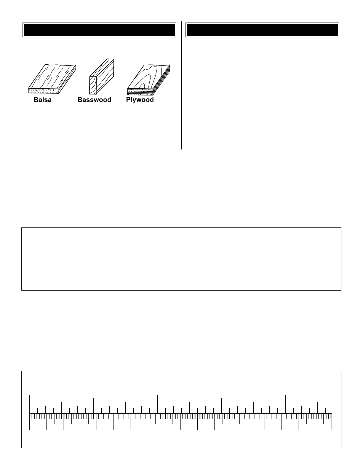
TYPES OF WOOD..............................................................................6
GET READY TO BUILD......................................................................6
METRIC CONVERSIONS...................................................................6
METRIC/INCH SCALE.......................................................................6
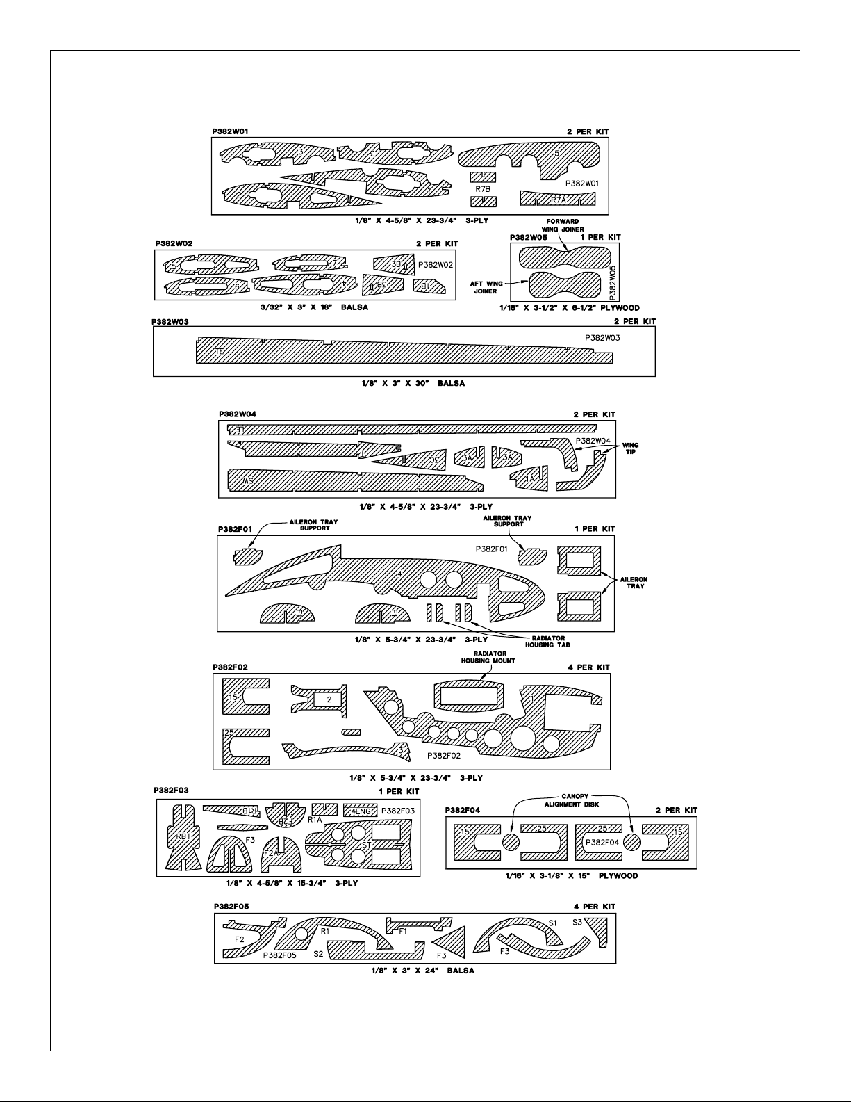
DIE-CUT DRAWINGS.........................................................................7
BUILD THE T AIL SURFACES............................................................8
Build the Stabilizer ......................................................................8
Build the Elevator........................................................................9
Build the Rudder .........................................................................9
BUILD THE WING.............................................................................10
Build the Wing Panels...............................................................10
Sheet the Wing Panel................................................................12
Join the Wing Panels.................................................................13
Sheet the Top of the Wing.........................................................14
BUILD THE BOOMS & FINS ...........................................................19
Assemble the Boom..................................................................19
Sheet the Boom ........................................................................20
Assemble the Engine Mounts ...................................................22
Attach the Rudder to the Fin.....................................................23
INST ALL THE ENGINES..................................................................24
MOUNT THE BOOMS ON THE WING.............................................25
Prepare the Booms & Wing.......................................................25
Install the Ailerons .....................................................................26
Build the Canopy Frame............................................................27
Fit the Canopy on the Frame ....................................................28
INSTALL THE RADIO SYSTEM.......................................................30
Install the Aileron Servos ..........................................................30
Install the Elevator & Rudder Servos........................................31
Install the Elevator Pushrod......................................................32
Connect the Rudders................................................................33
Install the Throttle Servo...........................................................34
Install the Nose Steering...........................................................35
Balance the Airplane Laterally ..................................................35
FINISHING........................................................................................36
Final Sanding ............................................................................36
Cover the Model with MonoKote
®
Film......................................36
Suggested Covering Sequence ................................................37
Painting Your Model...................................................................37
Installing & Painting the Radiators............................................37
Applying the Decals ..................................................................38
FINAL HOOKUPS AND CHECKS...................................................38
Install the Hinges.......................................................................38
Install the Landing Gear............................................................39
Install the Engines & Fuel Tanks...............................................40
Install the Canopy......................................................................40
GET THE MODEL READY TO FLY ..................................................41
Check the Control Directions ....................................................41
Set the Control Throws..............................................................41
Balance the Model (CG) ...........................................................42
PREFLIGHT......................................................................................43
Identify Y our Model....................................................................43
Charge the Batteries.................................................................43
Balance the Propellers..............................................................43
Ground Check...........................................................................43
Range Check.............................................................................43
ENGINE SAFETY PRECAUTIONS..................................................43
AMA SAFETY CODE (excerpt).......................................................44
CHECK LIST ....................................................................................44
FLYING .............................................................................................45
Engine Setup.............................................................................45
Takeoff.......................................................................................45
Flight..........................................................................................45
What To Do If One Engine Quits ...............................................45
Landing......................................................................................46
TWO VIEW DRAWING............................................Back Cover Page
FUSE & WING PLANS ................................Center Pull-Out Section
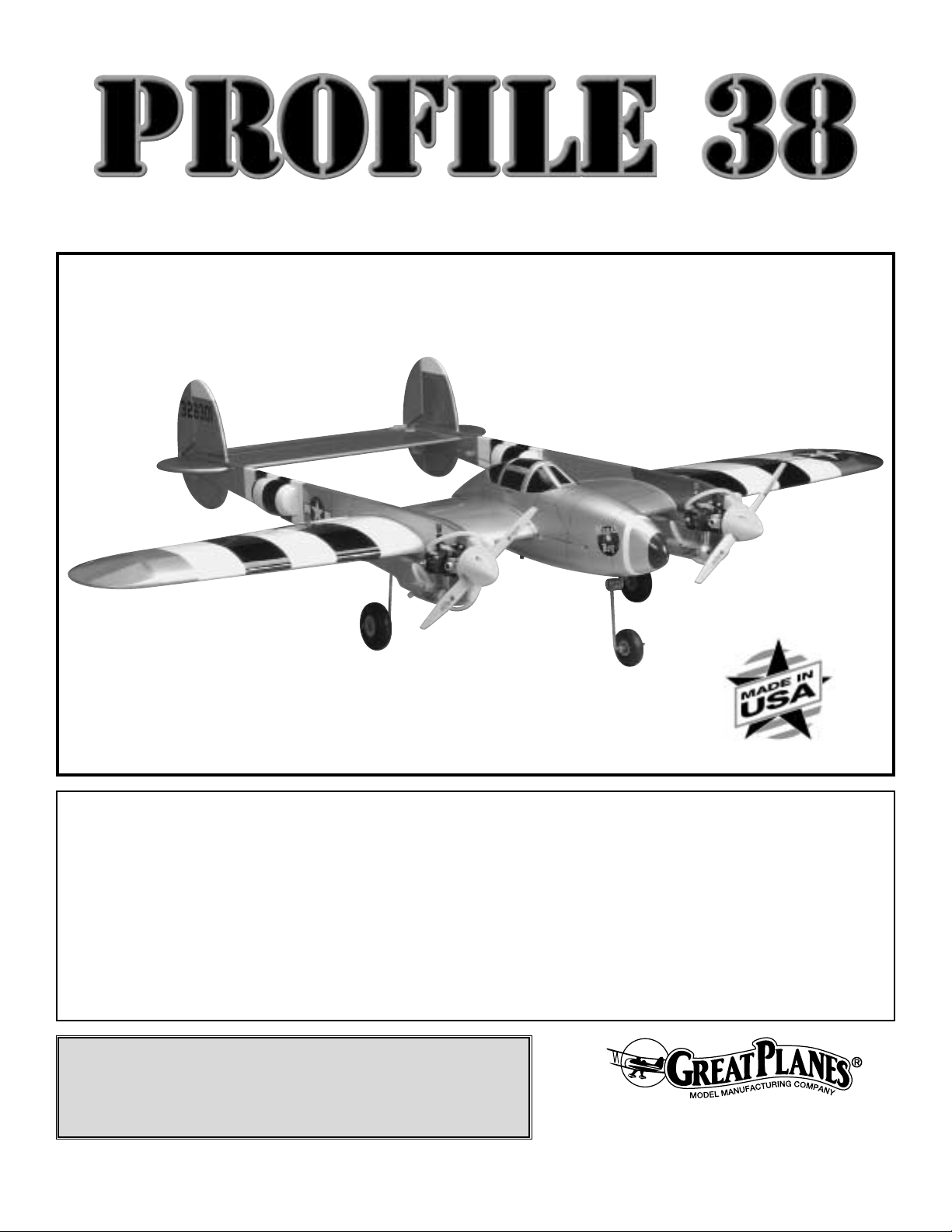
Along with the P-51, the P-38 is one of the most admired
planes of WW2. It is also one of the most difficult to build
and fly. But the Great Planes Profile 38 has eliminated those
hurdles. The booms of the Great Planes Profile 38 build
quickly and flat on your building board. The center pod is
molded from ABS, eliminating the difficult job of sheeting the
compound curves.Through extensive testing and design we
have minimized the flight problems that occur when an
engine quits in flight. So if you’re ready for an easy building,
fun to fly plane, let’s get started.
While the Profile 38 is easy to fly, it does not have the total
self-recovery and stability of a basic trainer like the Great
Planes series of PT basic trainers. Therefore, if you have
never flo wn an R/C airplane before, we strongly recommend
that you do not attempt to fly the Profile 38 without first
learning to fly a trainer. On the other hand, if you have
already become proficient at flying low wing airplanes, the
Profile
38 is an excellent choice for your first twin engine plane.
For the latest technical updates or manual corrections to the
Profile 38, visit the web site listed below and select the
Great Planes Profile 38.If there is new technical information
or changes to this kit a “tech notice” box will appear in the
upper left corner of the page.
http://www.greatplanes.com/airplanes/index.html
If you would like photos of the full-size P-38 to study the
photos
to add more scale details, photo packs are available from:
Bob’s Aircraft Documentation
3114 Y uk on Av e.
Costa Mesa, CA 92626
Telephone: (714) 979-8058
Fax:(714) 979-7279
E-mail:
www.bobsairdoc.com
Scale Covering Schemes
INTRODUCTION
TABLE OF CONTENTS
2
Page 3
1.Your Profile 38 should not be considered a toy, but rather
a sophisticated, working model that functions very much like
a full-size airplane. Because of its performance capabilities,
the Profile 38, if not assembled and operated correctly,
could possibly cause injury to yourself or spectators and
damage to property.
2. You must assemble the model according to the
instructions. Do not alter or modify the model, as doing so
may result in an unsafe or unflyable model. In a few cases
the instructions may differ slightly from the photos.In those
instances the written instructions should be considered as
correct.
3.You must take time to build straight, true and strong.
4. You must use an R/C radio system that is in first-class
condition, and a correctly sized engine and components
(fuel tank, wheels, etc.) throughout the building process.
5. You must correctly install all R/C and other components
so that the model operates correctly on the ground and in
the air.
6.You must check the operation of the model before every
flight to insure that all equipment is operating and that the
model has remained structurally sound. Be sure to check
clevises or other connectors often and replace them if they
show any signs of wear or fatigue.
7. If you are not already an experienced R/C pilot, you
should fly the model only with the help of a competent,
experienced R/C pilot.
8.While this kit has been flight tested to exceed normal use,
if the plane will be used for extremely high stress flying,
such as racing, the modeler is responsible for taking steps
to reinforce the high stress points.
Remember: Take your time and follow the instructions
to end up with a well-built model that is straight and
true.
Before starting to build, compare the parts in this kit
with the Parts List, and note any missing parts. Also
inspect all parts to make sure they are of acceptable
quality. If any parts are missing, broken or defective, or
if you have any questions about building or flying this
airplane, please contact Great Planes at the address or
telephone number below. If you are contacting us for
replacement parts, please be sure to provide the full kit
name (Profile 38) and the part numbers as listed in the
Parts List.
Great Planes Product Support:
3002 N Apollo Drive, Suite 1
Champaign, IL 61822
Telephone: (217) 398-8970
Fax:(217) 398-7721
E-mail:
productsupport@greatplanes.com
Y ou can also c heck our web site at
www.greatplanes.com
for the latest Profile 38 updates.
If you have not flown this type of model before, we
recommend that you get the assistance of an experienced
pilot in your R/C club for your first flights. If you’re not a
member of a club, your local hobby shop has information
about clubs in your area whose membership includes
experienced pilots.
In addition to joining an R/C club, we strongly recommend
you join the AMA (Academy of Model Aeronautics). AMA
membership is required to fly at AMA sanctioned clubs.
There are over 2,500 AMA chartered clubs across the
country. Among other benefits, the AMA provides insurance
to its members who fly at sanctioned sites and events.
Additionally, training programs and instructors are available
at AMA club sites to help you get started the right way.
Contact
the AMA at the address or toll-free phone number below:
Recommended Engine Size: .15 to .25 cu. in. 2-stroke
Two .15 size engines will fly the Profile 38 well. However,
if one engine quits in the air, the plane will not have
enough power to maintain level flight.The plane will have
to land. With two .25 size engines, if one engine quits in
the air, the plane can continue flying on one engine.
Engine Selection
DECISIONS YOU MUST MAKE
Academy of Model Aeronautics
5151 East Memorial Drive
Muncie, IN 47302
Tele: (800) 435-9262
Fax (765) 741-0057
Or via the Internet at:
http://www.modelaircraft.org
We, as the kit manufacturer, provide you with a top
quality, thoroughly tested kit and instructions, but
ultimately the quality and flyability of your finished model
depends on how you build it;therefore, we cannot in any
way guarantee the performance of your completed
model, and no representations are expressed or implied
as to the performance or safety of your completed model.
PRO TECT YOUR MODEL,YOURSELF
& OTHERS...FOLLOW THESE
IMPORTANT SAFETY PRECAUTIONS
3
Page 4

❏ Engine and suitable propellers
❏ 4-Channel radio with 6 standard servos
❏ (2) 12" [300mm] Servo extension (HCAM2711 for
Futaba
®
)
❏ (2) Y-harnesses (HCAM2751 for Futaba)
❏ 1/4" [6mm] R/C foam rubber (HCAQ1000)
❏ (2) 4 oz. [120cc] Fuel tank (GPMQ4101)
❏ 3' [900mm] Standard silicone fuel tubing (GPMQ4131)
❏ #64 Rubber bands (1/4 lb [113g] box, HCAQ2020)
❏ (1) 2" [51mm] Nose wheel (GPMQ4221)
❏ (2) 2-1/2" [64mm] Main wheels (GPMQ4223)
❏ (2) 2" [51mm] White spinner (GPMQ4510)
❏ (2) Rolls covering film (if covering in one color), box
cover model was covered with:
Aluminum (TOPQ0205)
Black (TOPQ0208)
White (TOPQ0204)
Cub Yellow (TOPQ0220)
Olive Drab (TOPQ0210)
In addition to common household tools (screwdrivers, drill,
etc.), this is the “short list” of the most important items
required to build the Profile 38.
We recommend Great
Planes Pro™CA and Epoxy glue.
❏ 1 oz. [30g] Thin Pro CA (GPMR6002)
❏ 1 oz. [30g] Medium Pro CA+ (GPMR6008)
❏ Pro 30-minute epoxy (GPMR6047)
❏ Pro 6-minute epoxy (GPMR6045)
❏ HobbyLite
™
balsa-colored balsa filler (HCAR3401)
❏ Plan Protector
™
(GPMR6167) or wax paper
❏ Drill bits:1/16" [1.6mm], 3/32" [2.4mm], 7/64" [2.8mm],
1/8" [3.2mm], 5/32" [4mm], 3/16" [4.8mm],
❏ Small metal file
❏ Stick-on segmented lead weights (GPMQ4485)
❏ Silver solder w/flux (GPMR8070)
❏ #1 Hobby knife (HCAR0105)
❏ #11 Blades (100-pack, HCAR0311)
❏ Single-edge razor blades (10-pack, HCAR0212)
❏ Small T-pins (100, HCAR5100)
❏ Medium T-pins (100, HCAR5150)
❏ Sanding tools and sandpaper assortment (see
Expert
Tip–Easy-Touch™Bar Sander
section on page 5)
❏ Top Flite
®
MonoKote®sealing iron (TOPR2100)
or
❏ 21st Century
®
sealing iron (COVR2700)
❏
Top Flite Hot Sock™iron cover (TOPR2175)
or
❏
21st Century iron cover (COVR2702)
❏
Top Flite MonoKote trim seal iron (TOPR2200)
or
❏
21st Century trim seal iron (COVR2750)
❏
Top Flite MonoKote heat gun (TOPR2000)
Here is a list of optional tools mentioned in the manual that
will help you build the Profile 38.
❏
Pro Aliphatic resin (2 oz. [60g], GPMR6160)
❏
2 oz. [57g] Spray CA activator (GPMR6035)
❏
4 oz. [113g] Aerosol CA activator (GPMR634)
❏
CA applicator tips (HCAR3780)
❏
CA debonder (GPMR6039)
❏
Kyosho®masking film (KYOR1040)
❏
Epoxy brushes (6, GPMR8060)
❏
Mixing sticks (50, GPMR8055)
❏
Mixing cups (GPMR8056)
❏
Razor plane (MASR1510)
❏
Builder’s triangle set (HCAR0480)
❏ Metal template set (30°/60°/90° and 45° triangles,
HCAR0500)
❏
Scale warbird template (TOPQ2187)
❏
36" Metal ruler (HCAR0475)
❏ Curved-tip canopy scissors (for trimming plastic parts,
(HCAR0667)
❏
Pliers with wire cutter (HCAR0630)
❏
Robart Super Stand II (ROBP1402)
❏
18" x 24" [460 x 610mm] Builder’s cutting mat
(HCAR0455)
❏
16" x 48" [410 x 1220mm] Building board (GPMR6950)
❏
Hobbico®Duster™can of compressed air (HCAR5500)
❏
Masking tape (TOPR8018)
❏
Threadlocker™thread locking cement (GPMR6060)
❏
Denatured alcohol (for epoxy clean up)
❏
Panel Line Pen (TOPQ2510)
❏
Z-bend pliers (HCAR2000)
❏
Rotary tool such as Dremel®Moto-Tool
®
❏
Rotary tool reinforced cut-off wheel (GPMR8200)
❏
Servo horn drill (HCAR0698)
❏
Hobby Heat™micro torch (HCAR0750)
❏
Dead Center™Engine Mount Hole Locator (GPMR8130)
❏
AccuThrow™Deflection Gauge (GPMR2405)
❏
Slot Machine™ hinge slotting tool (110V, GPMR4010)
❏
CG Machine™(GPMR2400)
❏
Laser incidence meter (GPMR4020)
❏
Precision Magnetic Prop Balancer™(TOPQ5700)
Optional Supplies & Tools
Covering T ools
Adhesives & Building Supplies
Required Accessories
REQUIRED ITEMS
4
Page 5
• There are two types of screws used in this kit:
Sheet metal screws are designated by a number and a
length.
For example #6 x 3/4"
This is a number six screw that is 3/4" long.
Machine screws are designated by a number, threads per
inch, and a length.SHCS is just an abbreviation for “sock et
head
cap screw” and that is a machine screw with a socket head.
For example 4-40 x 3/4".
This is a number four screw that is 3/4" long with forty
threads per inch.
• When you see the term
test fit
in the instructions, it
means that you should first position the part on the
assembly without using any glue, then slightly modify or
custom fit the part as necessar y for the best fit.
• Whenever the term
glue
is written you should rely upon
your experience to decide what type of glue to use.When a
specific type of adhesive works best for that step, the
instructions will make a recommendation.
• Whenever just
epoxy
is specified you may use
either
30-minute (or 45-minute) epoxy or6-minute epoxy. When
30-minute epoxy is specified it is highly recommended that
you use only 30-minute (or 45-minute) epoxy, because you
will need the working time and/or the additional strength.
•
Photos
and
sketches
are placed before the step they
refer to. Frequently you can study photos in following steps
to get another view of the same parts.
Fuse = Fuselage
Stab = Horizontal Stabilizer
Fin = Ver tical Fin
LE = Leading Edge
TE = Trailing Edge
LG = Landing Gear
Ply = Plywood
" = Inches
mm = Millimeters
SHCS = Socket Head Cap Screw
COMMON ABBREVIATIONS
IMPORTANT BUILDING NOTES
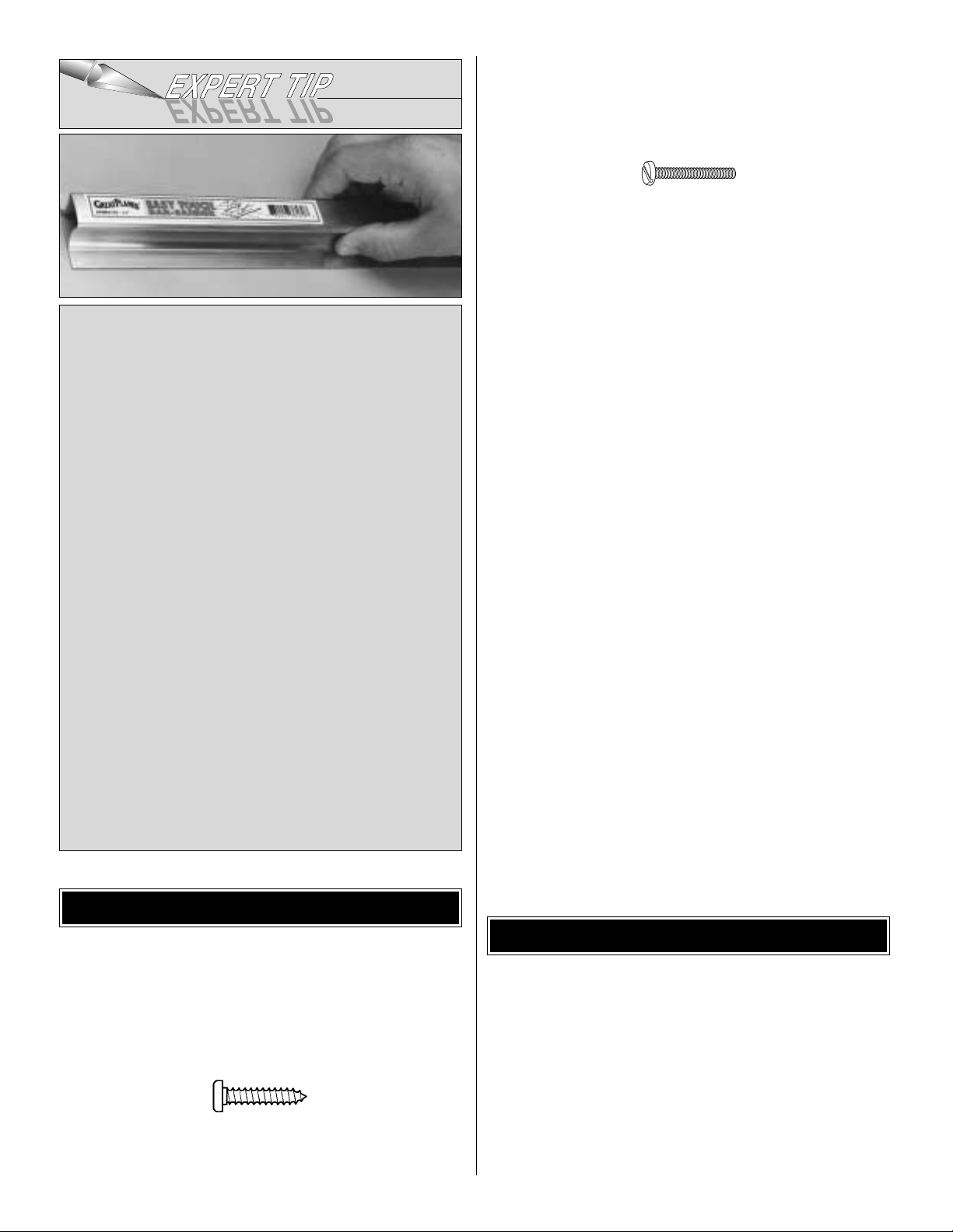
EASY-TOUCH™BAR SANDER
A flat, durable, easy to handle sanding tool is a necessity
for building a well finished model.Great Planes makes a
complete range of Easy-Touch Bar Sanders and
replaceable Easy-Touch Adhesive-backed Sandpaper.
While building the P-38 Profile, two 5-1/2" [140mm] Bar
Sanders and two 11" [280mm] Bar Sanders equipped
with 80-grit and 150-grit Adhesive-backed Sandpaper
were used.
Here’s the complete list of Easy-Touch Bar Sanders and
Adhesive Backed Sandpaper:
5-1/2" [140mm] Bar Sander (GPMR6169)
11" [280mm] Bar Sander (GPMR6170)
22" [560mm] Bar Sander (GPMR6172)
33" [840mm] Bar Sander (GPMR6174)
44" [1120mm] Bar Sander (GPMR6176)
11" [280mm] Contour Multi-Sander (GPMR6190)
12' [3.66m] roll of Adhesive-backed 80-grit sandpaper
(GPMR6180)
150-grit (GPMR6183)
180-grit (GPMR6184)
220-grit (GPMR6185)
Assortment pack of 5-1/2" [140mm] strips (GPMR6189)
We also use Top Flite 320-grit (TOPR8030, 4 sheets) and
400-grit (TOPR8032, 4 sheets) wet-or-dry sandpaper for
finish sanding.
5
Page 6
1.Unroll the plan sheet. Re-roll it inside out to make it lie
flat.
2. Remove all parts from the box. As you do, figure out the
name of each part by comparing it with the plans and the
parts list included with this kit. Using a felt-tip or ballpoint
pen, lightly write the part name or size on each piece to
avoid confusion later. Use the die-cut drawings shown on
page 7 to identify the die-cut parts and mark them before
removing them from the sheet. Save all scraps. If any of
the die-cut parts are difficult to punch out, do not force
them! Instead, cut around the parts with a hobby knife.After
punching out the die-cut parts, use your Bar Sander or
sanding block to lightly sand the edges to remove any diecutting irregularities or slivers.
GET READY TO BUILDTYPES OF WOOD
6
0" 1" 2" 3" 4" 5" 6" 7"
0 10 20 30 40 50 60 70 80 90 100 110 120 130 140 150 160 170 180
Inch Scale
Metric Scale
1/64" = .4 mm
1/32" = .8 mm
1/16" = 1.6 mm
3/32" = 2.4 mm
1/8" = 3.2 mm
5/32" = 4.0 mm
3/16" = 4.8 mm
1/4" = 6.4 mm
METRIC CONVERSIONS
3/8" = 9.5 mm
1/2" = 12.7 mm
5/8" = 15.9 mm
3/4" = 19.0 mm
1" = 25.4 mm
2" = 50.8 mm
3" = 76.2 mm
6" = 152.4 mm
12" = 304.8 mm
18" = 457.2 mm
21" = 533.4 mm
24" = 609.6 mm
30" = 762.0 mm
36" = 914.4 mm
Page 7
7
DIE-CUT DRAWINGS
Page 8
8
❏ 1.Unroll the plan sheets.Roll them inside out so they will
lie flat.
❏ 2.Position the wing plan so the stab plan is over your flat
building board. Cover the plan with Great Planes Plan
Protector™or wax paper so glue will not adhere.
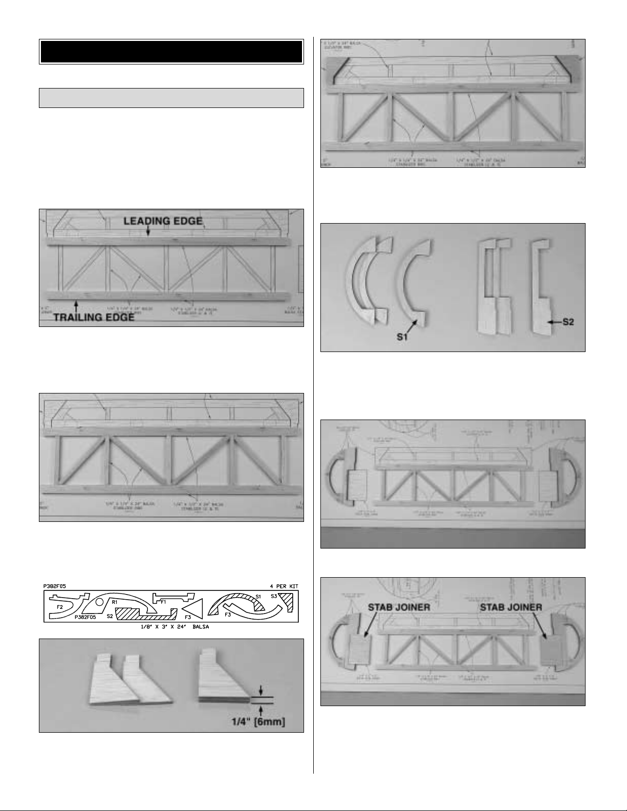
❏ 3. From two of the straightest 1/4" x 1/2" x 24" [6mm x
13mm x 610mm] balsa sticks, cut the stabilizer leading
and trailing edge to match the stabilizer plan.Pin the
leading
and trailing edge over the plan.
❏ 4. From 1/4" x 1/4" x 30" [6mm x 6mm x 762mm] balsa
sticks, cut and glue the stabilizer ribs between the leading
and trailing edge.
❏ 5. Locate the four die-cut 1/8" [3mm] balsa S3 stabilizer
tips. Make two sets of S3’s by gluing two of the 1/8" [3mm]
S3’s together to make 1/4" (6mm) thick S3’s.
❏ 6. Glue the S3 stabilizer tips to the trailing edge of the
stabilizer.
❏ 7. Locate the four die-cut 1/8" [3mm] balsa S1 and S2
stabilizer tips. Glue two of the S1’s together and two of the
S2’s together to make two 1/4" (6mm) thick S1’s and S2’s.
❏ 8. Pin S1 to the stabilizer tip plan. Pin and glue S2 to S1.
❏ 9. From the 1/4" x 3" x 5" [6mm x 76mm x 127mm] balsa
sheet, cut two stabilizer joiners as shown on the stabilizer
plan. Glue the joiners to S2.The stabilizer tips will be glued
to the stabilizer later when the main booms are attached to
the wing.
Build the Stabilizer
BUILD THE T AIL SURF ACES
Page 9
❏ 10.Remove the stab from your b uilding board.Inspect all
the glue joints and add CA to any joints that don’t look
strong. Fill any gaps with balsa sanding dust and a drop or
two of thin CA.
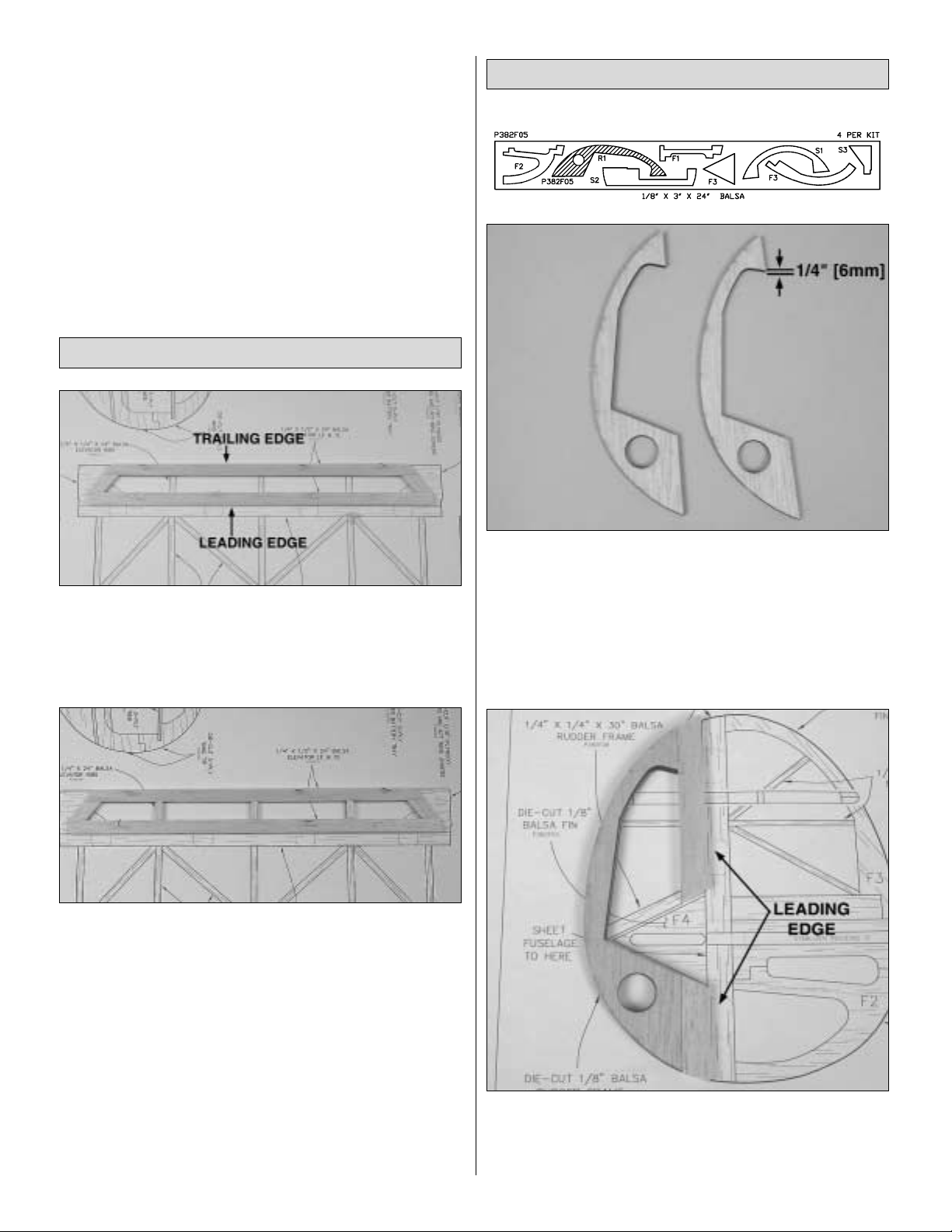
❏ 1. From two 1/4" x 1/2" x 24" [6mm x 13mm x 610mm]
balsa sticks, cut the elevator leading and trailing edge to
match the elevator plan. Pin the leading and trailing edge
over the plan.Cut and glue the elevator ends to the leading
and trailing edge.
❏ 2. From a 1/4" x 1/4" x 30" [6mm x 6mm x 762mm] balsa
stick, cut and glue the elevator ribs between the leading
and trailing edge.
❏ 3. From the remaining 1/4" x 1/2" x 24" [6mm x 13mm x
610mm] balsa stick, cut and glue gussets in the corner
between the elevator leading edge and elevator ends.
❏ 4. Remove the elevator from your building board. Inspect
all the glue joints and add CA to any joints that don’t look
strong. Fill any gaps with balsa sanding dust and a drop or
two of thin CA.First sand both sides of the stab and elevator
flat and even.Then, round the edges of the stab and
elevator
as shown on the plan.
❏ 1. Locate the four die-cut 1/8" [3mm] balsa R1 rudder
trailing edges. Glue two of the R1’s together to make two
1/4" [6mm] thick R1’s.
❏ 2. Position the fuse plan so the rudder plan is over your
flat building board. Cover the plan with Great Planes Plan
Protector or wax paper so glue will not adhere.
❏❏3. Pin the rudder trailing edge over the plan.
❏❏4. From remaining 1/4" x 1/2" x 24" [6mm x 13mm x
610mm] balsa sticks, cut the rudder leading edge to match
the rudder plan. Pin and glue the leading edge to the die-cut
trailing edge.
Build the Rudder
Build the Elevator
9
Page 10
❏❏5. From the 1/4" x 1/4" x 30" [6mm x 6mm x 762mm]
and 1/8" x 1/4" x 24" [3mm x 6mm x 610mm] balsa sticks,
cut and glue ribs to the leading and trailing edges.
❏❏6.Remove the rudder from your building board.
Inspect
all the glue joints and add CA to any joints that don’t look
strong. Fill any gaps with balsa sanding dust and a drop or
two of thin CA. Use a bar sander to sand both sides of the
rudder flat and even.
❏ 7. Return to step 2 and build the second rudder.
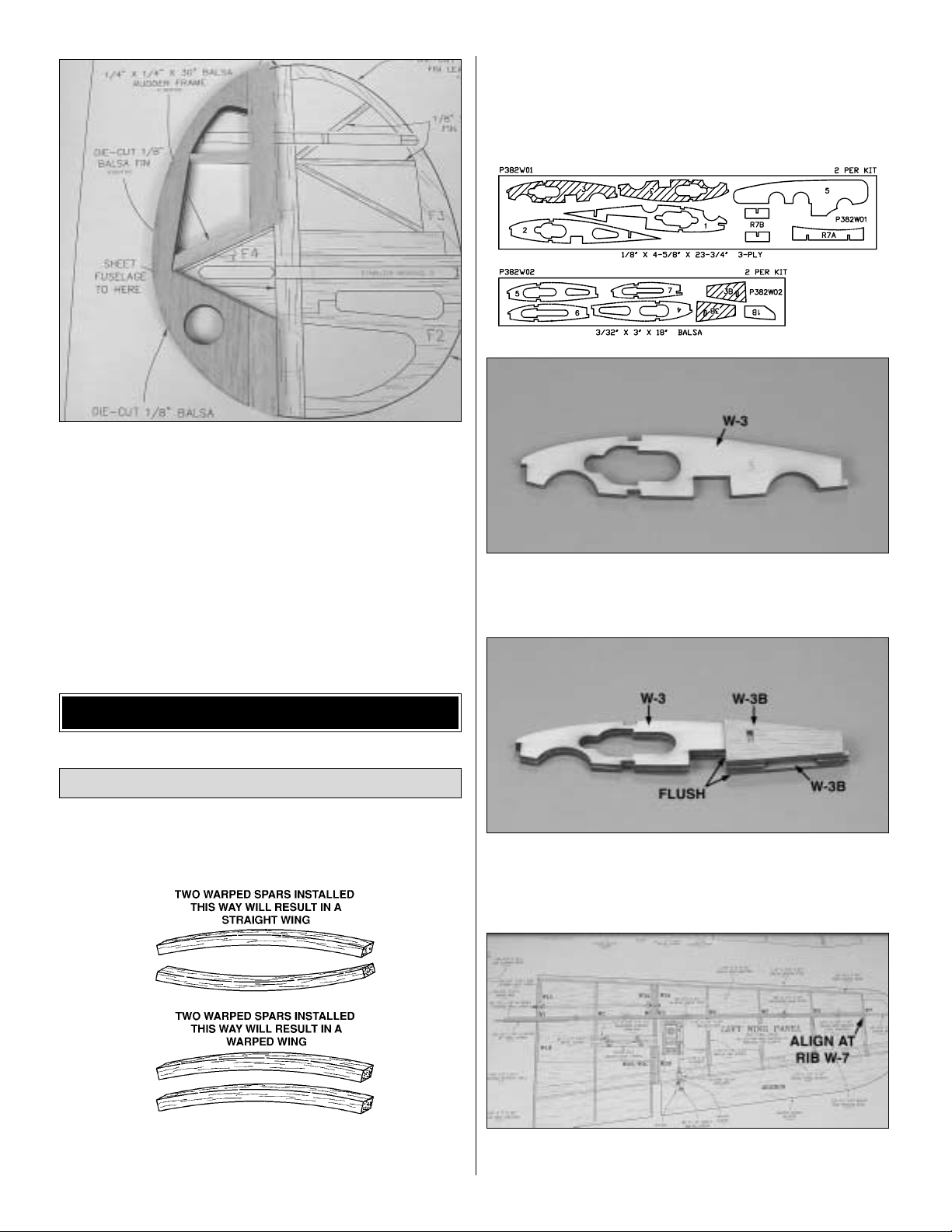
Start by building the left wing panel upside-down over the
left wing panel plan so your progress matches the photos.
❏ 1. Match the four 1/8" x 1/4" x 24" [3mm x 6mm x 610mm]
basswood main spars so any w arps will counteract each
other.
❏ 2. Cover the wing panel plan with waxed paper or Great
Planes Plan Protector.
❏❏3. Glue two of the die-cut 3-ply W-3 ribs together.
❏❏4. Glue the die-cut 3/32" [2mm] balsa W-3B ribs to
both sides of the aft end of the W-3 rib.
❏❏5. Position one of the main spars over the plan. Align
the end of the main spar with the outboard edge of rib W-7.
Build the Wing Panels
BUILD THE WING
10
Page 11
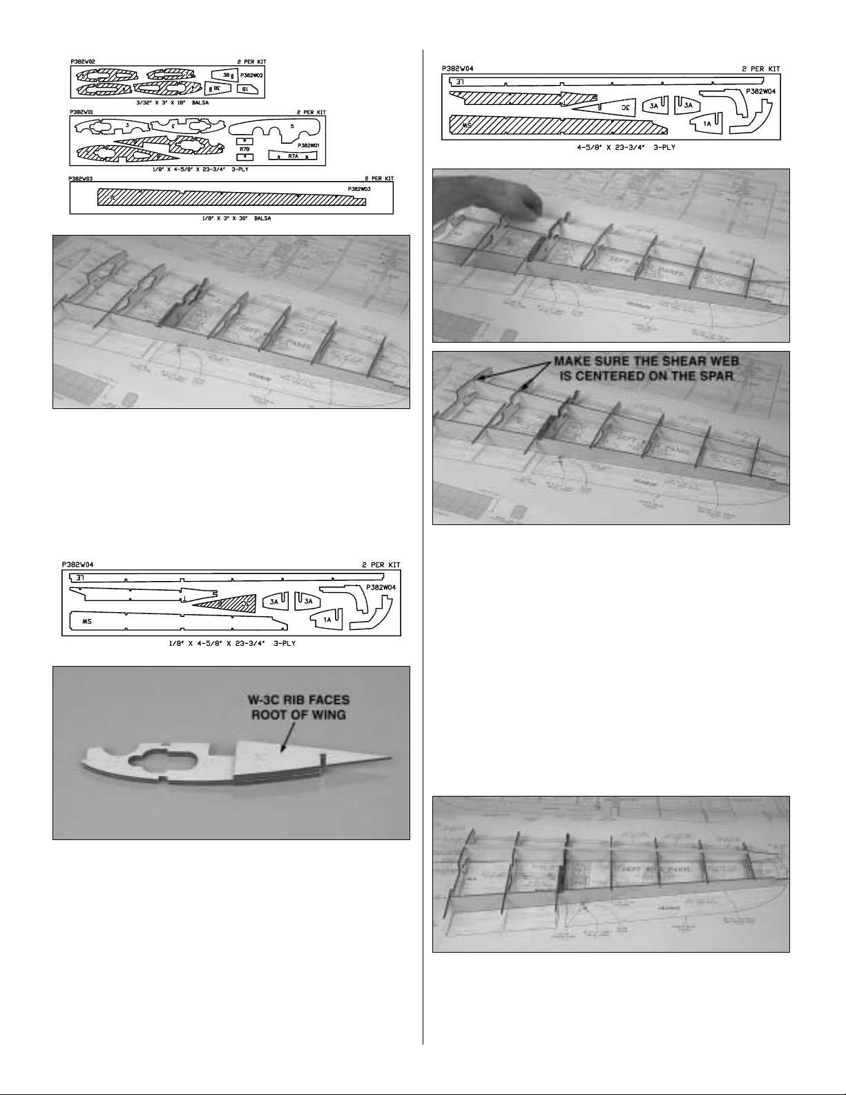
❏❏6. Pin the die-cut 1/8" [3mm] balsa sub-trailing edge
over the plan, perpendicular to the building board. Position
the die-cut ribs on the main spar, inserting the aft end of the
ribs in the notches of the sub-trailing edge.
❏❏7.Note which side of rib W-3 faces the root of the
wing.
Remove W -3 and glue the die-cut 3-ply W -3C rib to this side.
❏❏8. Reinstall W-3 on the main spar and sub-trailing
edge. Repin the main spar to your building board with the
pins outside of rib W-1. Pin rib W-7 perpendicular to your
building board.Remove the remaining pins holding the main
spar to the building board. This will allow the shear web to
be installed in the next step.
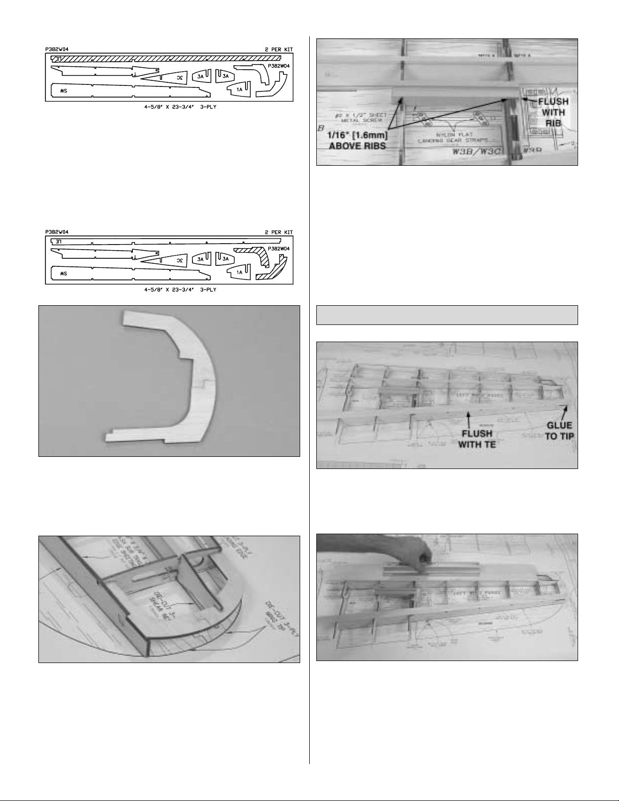
❏❏9.Glue the two-piece die-cut 3-ply shear web
together.
Use a straightedge to keep the two pieces aligned.From the
root rib, insert the shear web through the center of the ribs.
Carefully rotate it so that the “T”on the shear web is towards
your building board and the notches are aligned with the
ribs.Position the shear web so that it is as far bac k in the rib
as possible. The shear web will be centered on the main
spar.Pay special attention at ribs 1 and 2.
❏❏10.Pin the ribs to your building board next to the main
spar. Once the shear web is in position, glue it to the ribs
and the main spar.
❏❏11. With the ribs fully seated in the sub-trailing edge,
glue the ribs to the sub-trailing edge.
❏❏12.T est fit the second main spar in the ribs.Make sure
it is flush with the top of the ribs. Once satisfied with the fit,
remove the spar and apply a bead of medium CA along the
top edge of the shear web and the main spar notch of the
ribs and reinstall the spar.
11
Page 12
❏❏13. Position the die-cut 3-ply sub-leading edge over
the tabs on the front of the ribs.As you glue the sub-leading
edge to the ribs, make sure the sub-trailing edge and main
spar is down on your building board.
❏❏14. Glue the two die-cut 3-ply wing tip pieces together
as shown on the plan.
❏❏15. Glue the wing tip to the sub-trailing edge, shear web
and rib W-7.
❏❏16.Using a sanding bar with 220-grit sandpaper,
lightly
sand the top of the ribs, main spar, sub-leading edge and
sub-trailing edge all flush.
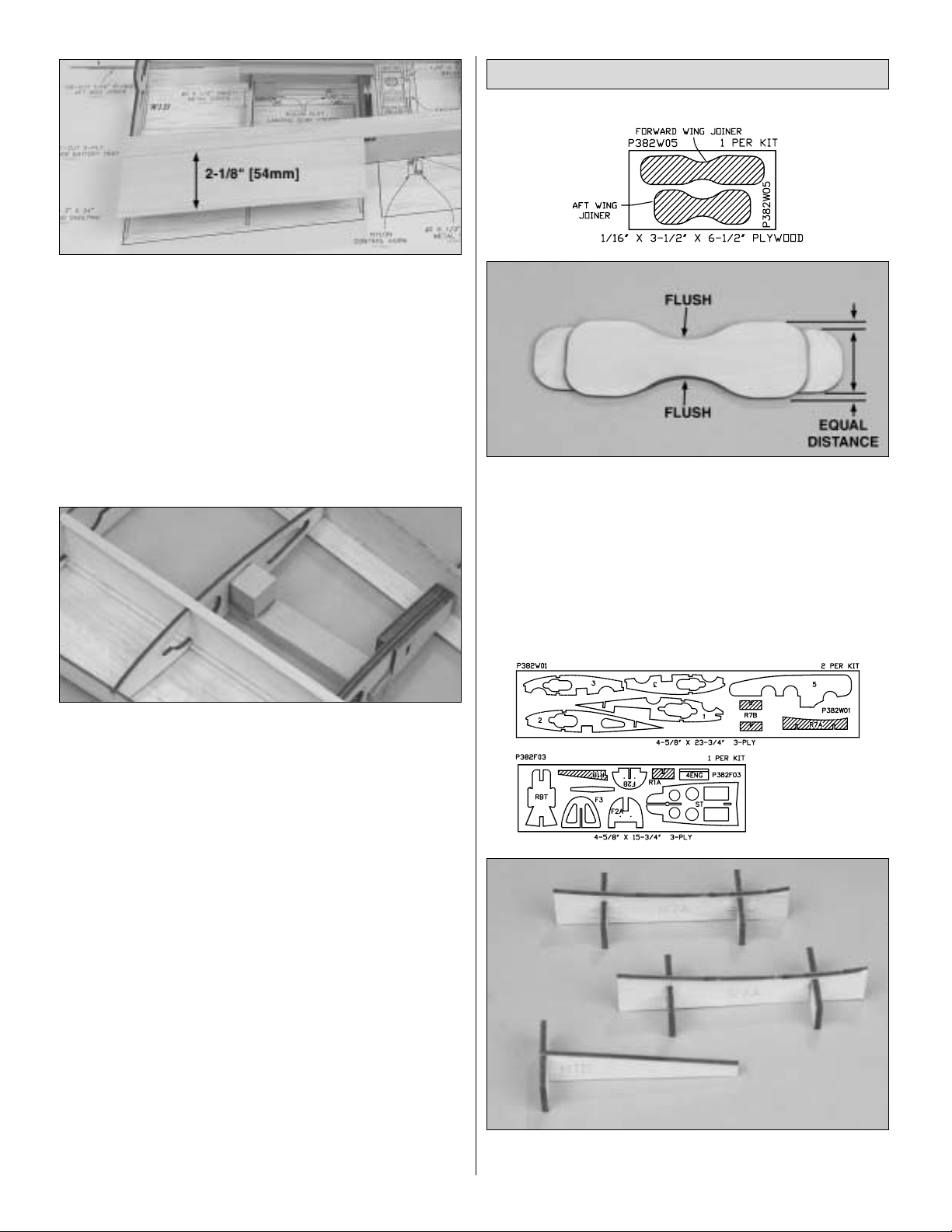
❏❏17.Use epoxy to glue the hardwood landing gear rail
in
the notches of ribs W-2 and W-3. Make sure that the landing
gear rail protrudes above the ribs by 1/16" [1.6mm] and is
flush with the side of rib W-3. Before the epoxy hardens,
wipe off any excess from rib W-2 using a paper towel
dampened with denatured alcohol.
❏1.From one of the 1/16" x 3" x 30" [1.6mm x 76mm x
762mm]
balsa sheets, cut a 1/16" x 5/8" x 30" [1.6mm x 16mm x
762mm] trailing edge strip. Glue the strip to the sub-
trailing
edge, ribs W-1 through W-7 and the wing tip.
❏❏2.T rue one edge of a 1/16" x 3" x 24" [1.6mm x 76mm
x 610mm) balsa sheet to make a leading edge sheet.The
sheet is installed from the middle of the main spar to the
sub-leading edge by first applying medium CA along the
front half of the main spar, the edge of the ribs and the subleading edge. Position the sheet on the main spar and
slowly press the sheet down onto the ribs and leading edge.
Use a sanding bar to press the sheet down evenly.
Sheet the Wing Panels
12
Page 13
❏❏
3. From a second 1/16" x 3" x 30" [1.6mm x 76mm x
762mm] balsa sheet, make a trailing edge sheet to fit from
rib W-1 to W-3. Cut the sheet 2-1/8" [54mm] wide. Glue the
sheet to the trailing edge strip and the top of the ribs.
❏❏4. Remove the wing panel from your building board.
Check all the glue joints. Pay special attention to the joint
between the shear web and the main spars.The shear web
must be securely glued to the main spar.
❏❏5. Tr im the sheeting flush with rib W-1 and the sub-
leading edge.
❏❏6. Use epoxy to glue the 3/4" x 3/4" x 3/4" [19mm x
19mm x 19mm] hardwood landing gear torque block to
the landing gear rail and rib W-2.
❏ 7. Return to step 2 and build the right wing panel.
❏ 1. Use epoxy to glue the two die-cut 1/16" [1.6mm]
plywood
wing joiners together, aligning the joiners at the center.
Before the epoxy hardens, wipe off any excess with a paper
towel dampened with denatured alcohol.
❏ 2. Assemble and glue the two die-cut 3-ply R7A and one
R1B rib jigs.
Join the Wing Panels
13
Page 14
❏ 3. Fit the R7A jigs under the W-7 ribs and the R1B jig
under the W-1 ribs so that the aft edge of the jigs are flush
with the trailing edge of the wing. Apply 30-minute epoxy to
the root ribs and use clamps to hold the wing halves
together. Apply epoxy to the front of the wing joiner and
insert it through W-1 as shown.The forward joiner is against
the shear web and the aft joiner is against the main spars.
Wipe off any excess epoxy and use clamps to hold the
joiner in position until the epoxy cures.
❏ 4. Use epoxy to glue the die-cut 3-ply sub-leading edge
joiner in the front of the W-1 ribs and the sub-leading edge.
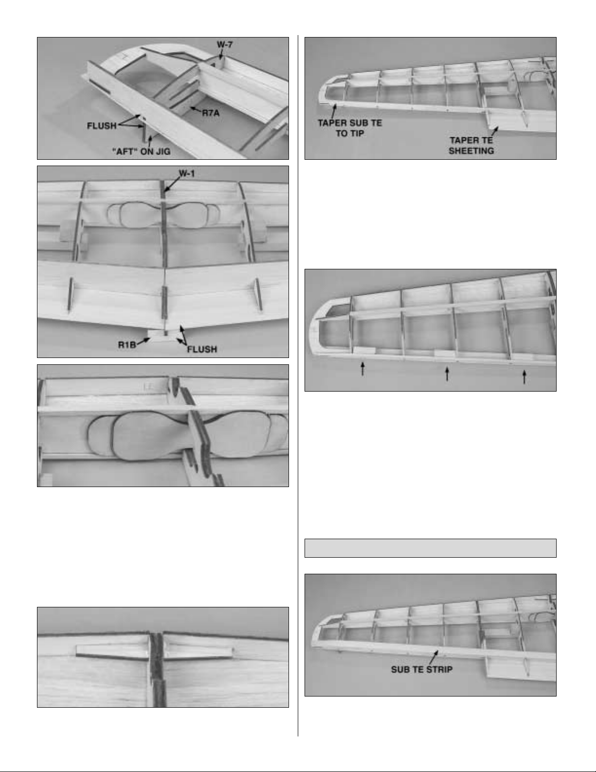
❏ 5. Use a planer and bar sander to trim the sub-trailing
edge flush with the top of the ribs. Taper the tip of the subtrailing edge so that the trailing edge strip can be glued to
the wing tip.
❏ 6. Use a bar sander to taper the trailing edge sheeting to
match the taper on ribs W-1 through W-3. See the wing
cross-section on the wing plan.
❏ 7. From the 1/2" x 1/2" x 12" [13mm x 13mm x 305mm]
balsa stick cut six 1-1/2" [38mm] long hinge blocks .Glue the
hinge blocks in position against the sub-trailing edge.
❏ 1.With the wing setting on the wing jigs, cut and glue 5/8"
[16mm] balsa sub-trailing edge strips to the top of the ribs
and the sub-trailing edge.
Sheet the Top of the Wing
14
Page 15
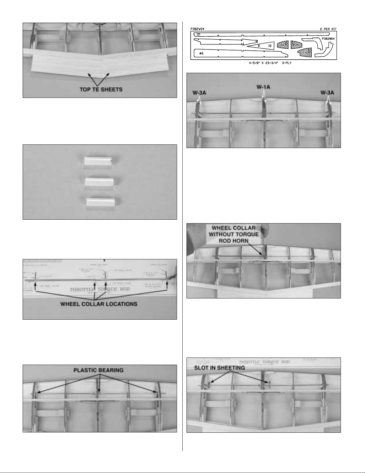
❏ 2. From the remaining 1/16" x 3" x 30" [1.6mm x 76mm x
762mm] balsa sheet, used to make the bottom trailing edge
sheet, and a second 1/16" x 3" x 30" [1.6mm x 76mm x
762mm] balsa sheet, make two top trailing edge sheets.
Glue the top trailing edge sheets in position.
❏ 3.Use 320-grit sandpaper to roughen the 1/8" x 5" [3mm
x 127mm] plastic tube. Cut three 5/8" [16mm] long throttle
torque rod bearings from the 1/8" x 5" [3mm x 127mm]
plastic tube.
❏ 4.Lay the 1/8" x 17-1/2" [3mm x 445mm] throttle torque
rod over the plan and mark the location of the four 1/8"
[3mm] wheel collars.Use a file to make a flat spot at each
wheel collar location.Make sure the flats are all on the same
side of the throttle torque rod.
❏ 5. Insert the throttle torque rod through the wing ribs and
position the wheel collars and plastic bearings on the rod.
❏ 6. Use epoxy to glue the die-cut 3-ply W-1A and W-3A
sub-ribs to both sides of the W-1 and W-3 ribs. Also glue
the throttle torque rod bearings to the ribs. Be careful to not
get epoxy in the plastic bearings. A light coat of grease on
the torque rod will prevent the epoxy from sticking to the
torque rod.Before the epoxy hardens, mak e sure the throttle
torque rod rotates freely.
❏ 7. Position the torque rod in its correct location. Apply a
drop of thread lock to a 4-40 set screw and secure the one
wheel collar, that will not ha v e a torque rod horn installed on
it, on the throttle torque rod. Make sure that the set screw is
tightened on the flat spot on the throttle torque rod.
❏ 8. With the three remaining wheel collars in position, cut
slots in the bottom sheeting under the wheel collars.
15
Page 16

❏ 9. Thread a 4-40 nut onto a 4-40 x 4-1/2" [114mm]
pushrod. Make an L-bend in the non-threaded end of the
pushrod. Important: Put a drop or two of thread lock or
epoxy at the end of the threaded end of the pushrod.
Without the thread lock or epoxy the pushrod will vibrate
loose. Insert the pushrod through the slot in the sheeting
and screw the pushrod into one of the wheel collars. Make
sure the pushrod is tightened on the flat spot on the throttle
torque rod. Tighten the 4-40 nut against the wheel collar.
Make sure the pushrod and nut are tight.
❏ 10. Install the remaining two pushrods in the other two
wheel
collars. The pushrods should be aligned with each other. If
the pushrods are not aligned, you may need to slightly
adjust the flat spots with a file.
❏ 11.Cut off the unthreaded portion of the pushrod.Thread
a nylon torque rod horn onto each pushrod so that the top
of the torque rod horn is flush with the end of the threads.
❏ 12. Use a bar sander to sand the top of the sub-leading
edges flush with the top of the ribs.
❏ 13.Position the wing back on its jigs.Use the two
remaining
1/16" x 3" x 24" [1.6mm x 76mm x 610mm] balsa sheets to
sheet from the center of the main spar to the sub-leading
edge. Note: You may need to enlarge the slots for the
throttle torque rod horns so that they can be rotated up into
the wing to allow the wing to set on the jigs.
❏ 14. Mark the center of the landing gear torque block on
the landing gear rail.Drill a 5/32" [4mm] hole through both
the
landing gear rail and torque block, perpendicular to the rail.
16
Page 17

❏ 15. Glue the die-cut 3-ply receiver battery tray to rib
W-1 and the sub-trailing edge.
❏ 16. From the 1/16" x 3" x 30" [1.6mm x 76mm x 762mm]
balsa sheet, cut three pieces 8-1/2" [216mm] long for the
wing center sheeting.Glue one piece against the leading
edge
sheet, between ribs W-1 and W-3. Mark the location of the
notch in rib W-1.Then, glue on the second sheet.
❏ 17.From the third sheet, fit and glue two pieces between
the trailing edge strip and the previous wing center sheeting.
❏ 18.From the 1/16" x 1/4" x 24" [1.6mm x 6mm x 610mm]
balsa stick, cut and glue cap strips to the top of ribs W-4
through W-7.
❏ 19.Glue the die-cut 3-ply aileron servo trays and
aileron
tray supports to ribs W-3 and the bottom of the main spar.
❏ 20. Glue the die-cut 3/32" [2mm] balsa sub-ribs W-1B to
each side of the W-1 rib over the notch.
❏ 21. From the 1/16" x 3" x 30" [1.6mm x 76mm x 762mm]
balsa sheet, cut three pieces 8-1/2" [216mm] long for the
bottom
wing center sheeting. Save the remaining sheet. The two
forward center sheets must be trimmed to fit around the
landing
gear rails so that they fit flush with the top of the rails.
17
Page 18

❏ 22. Once you have the 1/16" [1.6mm] center sheeting
trimmed to fit around the landing gear rail, glue the sheeting
to the main spar, bottom of the ribs and the landing gear rail.
Trim the sheeting from over the receiver battery tray.
❏ 23. From the third 8-1/2" [216mm] sheet, trim and glue
the aft center sheeting to the sub-trailing edge strip and the
top of the ribs.
❏ 24.From the 1/16" x 1/4" x 24" [1.6mm x 6mm x 610mm]
balsa stick, cut and glue cap strips to the bottom of ribs
W-4 through W-7.
❏ 25. Use a bar sander to sand the top and bottom leading
edge sheeting flush with the sub-leading edge.
❏ 26.Glue the two 1/4" x 3/4" x 24" [6mm x 19mm x
610mm]
balsa leading edges to the front of the sub-leading edge.
❏ 27.Using a razor plane and bar sander, round the
leading
edge to match the wing cross-section.
❏ 28. Trim the top sheeting from over the two alignment
slots in ribs W-1. The first slot is approximately 1" [25mm]
from the leading edge and the second one is approximately
5" [127mm] from the leading edge. A T-pin works great for
locating the slots.
C. Cut the hole for the landing gear rail slightly smaller.
Then, trim the sheeting to fit.
B. Position the sheeting against the aft edge of the
leading edge sheeting.Press down on the sheeting
around
the landing gear rail. This will leave a chalk mark on the
sheeting.
How To Locate Structure Under Sheeting
A. Using chalk, mark the outline of the landing gear rail.
18
Page 19

❏ 29.Trim the bottom sheeting from over the four alignment
slots in ribs W-3. The first slot is approximately 1" [25mm]
from the leading edge and the second one is approximately
5-5/8" [143mm] from the leading edge.
You can set the wing aside for now. We will install the
ailerons after we fit the two booms on the wing.
❏ 1. Cover the boom plan with wax paper or Great Planes
Plan Protector.
❏❏2. Glue two of the die-cut 3-ply boom main frames
(1) together. Make sure the edges are aligned.
❏❏3. Glue two of the die-cut 3-ply elevator and rudder
servo trays together.
❏❏4. Glue two of the die-cut 1/8" [3mm] balsa fin frame
F1, F2 and F3 together to make 1/4" [6mm] thick parts.
Assemble the Boom
BUILD THE BOOMS & FINS
19
Page 20

❏❏5. Pin the boom main frame, elevator and rudder
servo tray and the fin frame to your building board over the
boom plan. Glue the F1 and F2 fin frames together.
❏❏6. From the 1/4" x 1/4" x 30" [6mm x 6mm x 762mm]
balsa sticks, cut and glue an upper and lower boom frame
between the boom main frame, servo tray and the fin.
❏❏7. From the 1/4" x 1/2" x 24" [6mm x 13mm x 610mm]
balsa stick, cut and glue the fin trailing edge and lower
brace to the fin frame.
❏❏8.From 1/8" x 1/4" x 24" [3mm x 6mm x 610mm] balsa
sticks, cut and glue diagonal boom braces and fin ribs to
the boom frame.
❏❏9. Glue two of the die-cut 1/8" [3mm] balsa aft fins
(F4) together. Glue the aft fin to the trailing edge of the fin.
Note the direction of the wood grain.
❏ 10. Remove the boom from your building board and
return to step 2 and build the second boom.
❏❏1. Remove the boom from your building board. Use a
bar sander to sand both sides of the boom even.
❏❏2. Position the boom on top of a 1/16" x 3" x 30"
[1.6mm x 76mm x 762mm] balsa sheet.Align the sheet with
the front and top of the boom.Draw a line on the balsa sheet
along the bottom of the boom.
Sheet the Boom
20
Page 21

21
❏❏3. Use a straightedge to trim the sheet along the line
through the end of the sheet.
❏❏4. Check the fit of the sheet on the boom. Make sure
the sheet is flush with the top and bottom of the wing. With
the boom and balsa sheet flat on your building board, use
medium CA to glue the sheet to the boom.
❏❏5. Use a piece of leftover 1/16" [1.6mm] balsa sheet
from the wing to finish the aft sheeting. The sheet should
align with the trailing edge of the fin.
❏❏6. From a second 1/16" x 3" x 30" [1.6mm x 76mm x
762mm] balsa sheet, finish sheeting the bottom of the
boom.Tr im the sheet around the outside of the boom.
❏❏7. Using a sharp hobby knife, trim the sheeting from
inside the engine mount area, the servo tray and the
stabilizer saddle.
❏❏8.Trim the wing saddle as shown. Note that the sides
are straight with the sheeting overhanging the boom. Also
trim the sheeting from over the two mounting tabs.
❏❏9.Repeat the process to sheet the other side of the
boom.
❏ 10.Return to step 2 and sheet both sides of the other
boom.
❏❏11.Glue two of the die-cut 3-ply upper booms
together.
❏❏12. Pin the upper boom to the plan. Trim and glue a
leftover 1/4" x 1/4" [6mm x 6mm] balsa stick to the top of the
upper boom.
Page 22

❏❏13.Remove the upper boom from the plan.Using a
bar
sander, sand the upper boom even.
❏❏14. Test fit the upper boom to the main boom. Mark
the upper boom at the edge of the main boom sheeting.
❏❏15. Sheet one side of the upper boom with leftover
1/16" [1.6mm] balsa sheeting. Trim the sheeting along the
top and bottom and along the lines drawn in the previous
step.Turn the upper boom over and sheet the other side.
❏❏16. Test fit the upper boom to the main boom. The
sheeting does not have to mate perfectly. Later, after the
upper boom and main boom are glued to the wing, balsa
filler can be used to cover any imperfections.
❏17.Return to step 11 and assemble the second upper
boom.
❏ 1. Mark one of the main booms left and the other right; it
doesn’t matter which.
❏ 2. Decide what size engines you are going to use. We
have provided die-cut mounts for the O.S.®.15 LA and the
.25 LA. If you are using a different engine, you may need to
trim the mounts to fit your engine.The .15 size mounts have
a “15” embossed on them and the .25 size mounts have a
“25” embossed on them. Both mounts are assembled and
installed using the same method.
❏3.Locate the four die-cut 3-ply engine mount cores.Use
CA
to glue two of the cores together making a pair of engine
mounts.
❏ 4. Locate the four die-cut 1/16" [1.6mm] plywood engine
mount outers. Glue one of the outers to each side of the
engine mount cores.
❏ 5.Test fit the engine mounts in the cutouts at the front of
the main booms and trim as necessary.
Assemble the Engine Mounts
22
Page 23

❏ 6. Position the right main boom as shown.
❏ 7. Locate the die-cut 3-ply 4° engine gauge. With the
right main boom flat on your building table, position the
engine gauge at the aft edge of the engine mount.Raise the
aft edge of the engine mount until it is aligned with the
embossed line on the gauge.You may need to lightly sand
the engine mount to allow it to be rotated in the main boom.
Note: The right main boom has right thrust and the left main
boom has left thrust.
❏ 8. Once the engine mount is in position, use epoxy to
glue it in the main boom. Make sure the forward end of the
engine mount is flat on your building board and the aft end
is set to the line on the engine gauge. Wipe off any excess
epoxy with a paper towel dampened with denatured alcohol.
T-pins can be used to hold the engine mount in position until
the epoxy cures.
❏ 9. While the epoxy is curing on the right main boom,
position the left main boom flat on your building table.
Position the engine gauge at the front of the engine mount.
Raise the forward edge of the engine mount until it is
aligned with the embossed line on the gauge.You may need
to lightly sand the engine mount to allow it to be rotated in
the main boom.
❏ 10. Use leftover 1/16" [1.6mm] balsa sheet to fill in
behind
the engine mount.Sand the sheeting flush with the main
boom.
❏❏1. Lay the fin and rudder over the plan. Lightly mark
the hinge locations on the leading edge of the rudder and
the trailing edge of the fin.
❏❏2. Cutting hinge slots can be simplified with the Great
Planes Slot Machine™. This simple electric tool cuts a
perfect width slot for CA hinges.
❏❏3. To cut the hinge slots, first locate the centerline of
the leading and trailing edges using the Great Planes
Precision Hinge Marking Tool (GPMR4005). Place the
blades of the Slot Machine on the wood where you want the
slot. Lightly press the teeth into the wood. When you are
satisfied with the location, press the button on the handle
and the blades will cut easily into the balsa wood.
Attach the Rudder to the Fin
23
Page 24

❏❏4.Cut the 3/4" x 1" [19mm x 25mm] hinges for the
rudder
from the supplied 2" x 9" [51mm x 229mm] hinge material.
Then, snip off the corners as shown on the wing plan.
Temporarily join the rudder to the fin with the hinges,
adjusting any hinge slots if necessary so they all align. Do
not glue in the hinges until you are instructed to do so
after the airplane is covered.
❏❏5.With the rudder temporarily attached to the fin,
round
the leading edge of fin and the trailing edge of the rudder.
❏❏6. Refer to the
Expert Tip
that follows and shape the
leading edge of the rudder to a “V” as shown on the plan.
❏7.Return to step 1 and temporarily attach the second
rudder.
❏ 8. Repeat the process to hinge and make a “V” on the
elevator and stabilizer.
It is much easier to temporarily mount the engines now,
before the booms are permanently attached to the wing.
INST ALL THE ENGINES
B.Using the “bev el to”lines and the centerline as a guide,
make the “V” on the leading edge of the rudder with a
razor plane or the Great Planes Multi-Sander
(GPMR6190)
with 150-grit sandpaper.
How T o Bevel The Leading Edge
A. Place the leading edge of the rudder on your work
surface and use your pen to mark a “bevel to”line on both
sides, about 3/32" [2mm] high.
Note:Y ou will probab ly hav e to adjust the height of the
rudder
with card stock so your “bevel to” line is not too high.
If You Do Not Have A Slot Machine
Cut the hinge slots in the rudder and fin using a hobby
knife with a #11 blade. Mark the center line of the rudder
leading edge and the fin trailing edge. Begin by carefully
cutting a very shallow slit at the hinge location to
accurately establish the hinge slot. Make three or four
more cuts, going a little deeper each time. As you cut,
slide the knife from side to side until the slot has reached
the proper depth and width for the hinges.
24
Page 25

❏❏1. Mount the spinner backplate to the engine you are
using. Position the engine on the right boom engine mount.
The head of the engine should point to the right when
viewed from behind the plane. See the box lid if you are
confused. The backplate should be approximately 1/16" to
1/8" [1.6mm to 3mm] forward of the boom and the engine
should be centered in the mount. Trim the engine mount if
needed.
❏❏2.Mark the outline of the engine mounting lugs on the
boom. Use a sharp hobby knife to cut a recess in the balsa.
Do not cut into the plywood engine mount.
❏❏3. Position the engine in the recess and check its fit.
When satisfied, mark the location of the engine mounting
holes. A great method for marking the engine mounting
holes is to use the Great Planes Dead Center™Engine
Mounting Hole Locator.
❏❏4. Remove the engine from the boom. Drill a 7/64"
[2.8mm] diameter hole at each mark.Try to keep the drill bit
perpendicular to the engine mount.
❏❏5. Put a #4 flat washer on a 4-40 x 3/4" [19mm]
machine screw. Insert the screw through the back of the
engine mount and then through the engine mounting lugs.
Temporarily secure the engine to the mount with a #4 lock
washer and 4-40 nut.Install the other three screws, washers
and nuts.
❏ 6. Retur n to step 1 and install the second engine on the
left boom.
❏ 7. Once both engines have been mounted, remove them
and proceed to attaching the booms to the wing.
❏ 1. Sand a small radius along the top and bottom edges
of both booms. Fill any major dents with balsa filler.
❏ 2. Finish-sand the wing, removing any surface
blemishes.
Blend the wing sheeting and cap strips.Sand the shear web
at the wing tips so that it blends into the tip.Then, sand a
radius on both wing tips.
❏ 3. Test fit the left and r ight booms on the wing. The tabs
on the booms should fit snug in the slots in the wing. Trim
the slots slightly if they are too tight.
How To Remove Annoying Dents In Balsa
Many surface blemishes on a framed model are caused
by bumps and balsa chips on the work surface.This type
of “ding” is best repaired by applying a drop or two of tap
water to the blemish, then running a hot sealing iron over
the spot to expand the wood fibers.After the surface has
dried, sand the expanded area smooth.
Prepare the Booms & Wing
MOUNT THE BOOMS ON THE WING
25
Page 26

❏ 4. Slide the upper booms over the wing.
❏ 5. Insert the stabilizer tips in the boom.Position the
stabilizer
center between the booms so that the ends of the stabilizer
center are against the booms. With the booms and the
bottom of the fins resting on your building table and the
booms perpendicular to the table, measure the distance
between the booms at the leading and trailing edges of the
wing and at the leading edge of the stabilizer. All three
measurements must be the same. If they are not, you may
need to slightly trim the ends of the stabilizer center or the
slots in the wing.
❏ 6. Trim the stabilizer joiners so that the stabilizer center
fits against the boom and the joiner fits between the
stabilizer center leading edge, trailing edge and outer rib.
❏ 7. Once the booms are parallel and the stabilizer tips fit
well in the stabilizer center , use 30-min ute epoxy to glue the
main and upper booms to the wing, the stabilizer tips to the
booms and the stabilizer center to the booms and stabilizer
joiner.Make sure the main booms are perpendicular to your
building table. Check the measurements between the
booms before the epoxy hardens. Use a paper towel
dampened with denatured alcohol to wipe off any excess
epoxy before it hardens.
❏ 8.Use balsa filler to fill any open joints between the main
boom, the wing and the upper boom. Once the balsa filler
has dried, sand the upper boom so that it is flush with the
main boom.
❏❏1.Trim and sand the inboard end of the shaped balsa
aileron to match the angle of the main boom.Leave a 3/32"
[2mm] gap between the aileron and the main boom. Mar k
the three hinge locations on the aileron and the trailing edge
of the wing. Note: The center of the hinge should be in the
center of the 1/2" [13mm] hinge block.
❏❏2. Mark the centerline on the leading edge of the
aileron and the trailing edge of the wing. Cut the hinge slots
in the wing and aileron and temporarily install the aileron on
the wing. Use tape to hold the aileron tight against the
trailing edge of the wing.
❏❏3.T rim and sand the aileron to match the shape of the
wing tip.
❏❏4.Draw a line 3/32" [2mm] back from the leading edge
on both sides of the aileron. Use a razor plane and a bar
Install the Ailerons
26
Page 27

sander to make a “V” on the leading edge of the aileron.
Reinstall the aileron on the wing. Make sure that the aileron
can move up at least 1/2" [13mm] and down at least 1/2"
[13mm].
❏ 5. Return to step 1 and make the other aileron.
❏ 1. Glue the die-cut 3-ply canopy frame doublers (5) to
both sides of the die-cut 3-ply canopy frame (4), aligning
the edges of the frames and the two center holes.
❏ 2. Glue the four die-cut 1/16" [1.6mm] plywood canopy
alignment disks on each side of the alignment tabs on the
canopy frame.
❏ 3. Drill 1/16" [1.6mm] pilot holes at the punch marks in
the die-cut 3-ply formers F1, F2A and F2B.
❏4.Glue former F2A to the canopy frame so it is
perpendicular
to the frame.
❏ 5. Glue the die-cut 3-ply servo tray to the canopy frame
and former F2A, perpendicular to the frame.
Build the Canopy Frame
27
Page 28

❏ 6. Glue the die-cut former F2B to the bottom of the
canopy frame and former F2A. Make sure F2B is aligned
with F2A.
❏ 7. Lightly sand the front of the F2A/B formers to remove
any excess glue.Glue both die-cut formers F1 to the front of
the F2A/B formers.
❏ 8. Cut the nylon nose gear bearing in two and trim off
the “spreader bars.” Loosely attach the nose gear bear ings
to the back of the F2 formers using four #2 x 1/2" [13mm]
sheet metal screws. Insert the nose gear in the bearings,
then tighten the screws.
❏ 9. Test fit the canopy frame on the top of the wing. If the
alignment tabs are too tight in the slots you can lightly sand
the tabs. The frame should contact the top of the wing and
the aft edge of the servo tray should contact the leading
edge. Once satisfied with the fit, use epoxy to glue the
canopy frame and servo tray to the wing. Make sure the
canopy frame is straight.
❏ 10.Glue the die-cut 3-ply former F3 perpendicular to the
canopy frame and the top of the wing.
❏ 1. Tr im the ABS top canopy along the molded cut lines
where it fits over the wing. Cut the front half of the canopy
along the very bottom, below the cut line. Save the excess
plastic you cut off. You can use a hobby knife to carefully
Fit the Canopy on the Frame
28
Page 29

score along the cut lines and flex the plastic until the excess
breaks free, or use a Hobbico Curved-tip Canopy Scissors
(HCAR0667) to cut along the lines.
❏ 2. Trim the ABS bottom canopy the same way.
❏ 3. Fit the top canopy to the canopy frame.The lip of the
canopy should fully contact the top of the wing. Sand the
canopy frame if needed. Sand the edges of formers F1/F2
to match the angle of the servo tray. Make sure the canopy
frame does not cause the canopy to bulge out, especially at
formers F1/F2.When satisfied with the fit, use masking tape
to temporarily attach the canopy to the wing.
❏ 4. Turn the plane over and fit the bottom canopy on the
wing. Align the nose of the top and bottom canopy. Trim the
bottom canopy so that the edge of the bottom and top
canopy are flush.Take off a little at a time. A bar sander with
220-grit sandpaper works great for this.
❏ 5. Mark the location of former F1/F2 on the lip of the top
canopy. Mark the bottom canopy 3/8" [10mm] aft of the
former.
❏ 6. Cut the nose from the bottom canopy at these marks.
Wrap a piece of tape around the canopy, from mark-tomark, to act as a guide when cutting the canopy nose.
❏ 7.Sand the inside of the top canopy and the nose bottom
around the edges. From the scrap ABS, trimmed from the
canopies, make 1/2" [13mm] wide tabs to attach the top
canopy and the nose bottom.Use CA to glue the tabs to the
top canopy and the nose bottom.Do not glue the canopy to
the canopy frame at this time.The canopy will be attached
after the wing is covered and the canopy is painted. Do not
use CA kicker on the ABS. Over time it will cause the ABS
29
Page 30

to crack and if the residue is not completely removed, paint
will not adhere to it.
❏ 8. Sand the seam smooth between the top canopy and
the nose bottom. Fill the seam with a filler such as Bondo
®
Auto Body Filler or an automotive scratch and dent glazing
compound. We use Bondo most of the time as it cures
quickly and sands easily, but it is normally sold in large
quantities. Automotive glazing compound usually comes in
small tubes, dries quickly and sands easily, but for proper
drying can only be applied in thin layers.
❏ 9. After the filler hardens, sand off the excess, using
progressively finer sandpaper to smooth the seam. Wetsand the entire canopy, top and bottom, with 400-grit
sandpaper to prepare it for primer.
❏ 10.Temporarily reinstall the canopy on the canopy frame.
Use tape to hold it in place. Fit the canopy bottom on the
canopy top and trim as necessary.The aft end of the bottom
canopy should align with the trailing edge of the wing.From
scrap ABS, make four 1/2" x 1/2" [13mm x 13mm] square
canopy bottom tabs. Glue the tabs to the forward edge of
the bottom canopy .They should overhang the edge by 1/4"
[6mm].
❏ 11. Check fit the bottom canopy on the top canopy and
wing. Mounting blocks will be installed after the wing is
covered to hold the canopy bottom on the wing.
❏❏1. Install the aileron servos in the aileron servo trays
using the hardware provided with the servos.Note the servo
orientation in the photo and on the plan.
❏❏2. From the remaining 1/8" x 1/4" [3mm x 6mm] balsa
stick, cut and glue a frame around the aileron servo.This will
provide a surface for the covering to adhere to. Once you
remove the servo to cover the wing, use a bar sander to
sand the frame flush with the wing sheeting.
❏❏3.Temporarily plug the servo into the receiver.Switch
on the transmitter and then the receiver, and center the
aileron servo.Install a ser vo arm on the ser vo.
Install the Aileron Servos
INSTALL THE RADIO SYSTEM
30
Page 31

❏❏4. Thread a nylon clevis approximately 14 full turns
onto the threaded end of a 2-56 x 4" [102mm] pushrod.
Slide a silicone clevis retainer over the clevis.Remove the
backing plate from one of the large control horns and
connect the clevis to the control horn. Position the control
horn on the aileron so that the adjustment holes are aligned
with the aileron hinge line and the pushrod is parallel with
centerline of the servo.Mark the control horn mounting hole
locations on the aileron.
❏❏5. Attach the aileron control hor n to the aileron with
two #2 x 1/2" [13mm] sheet metal screws. Remove the
screws and put a drop of thin CA in each hole to harden the
wood. After the CA has hardened, reinstall the control horn
with the screws.
❏❏6. Center the aileron servo arm and mar k where the
pushrod crosses the arm. Make a 90° bend at the mark, cut
the pushrod and attach it to the servo arm with a Faslink.
❏ 7. Return to step 1,
Install the Aileron Servos
and
install the other aileron servo.
❏❏1. Using the hardware provided with the servo, install
the elevator servo in the servo tray of the left boom. Note its
orientation in the photo.
❏❏2.Tape the die-cut 3-ply radiator housing mount to
the boom, centered around the elevator servo.
❏❏3. Glue the die-cut 3-ply radiator tab to the radiator
tab base. Align the aft edge of the tab with the edge of the
tab base.
Install the Elevator & Rudder Servos
31
Page 32

❏❏4. Position the radiator tab over the aft edge of the
radiator housing mount.Mark the location of the radiator tab
on the main boom. Remove the radiator housing mount and
glue the radiator tab to the main boom, at the previous
mark.Allow the CA to cure and reinstall the radiator housing
mount, checking the fit. Make sure the radiator housing
mount remains centered.
❏❏5. Make a hole in front of the radiator housing mount
large enough for the servo plug to exit. Do not cut through
the sheeting on the outside of the main boom. A sharpened
brass tube works great for making holes in the sheeting.
❏❏6. Make a hole in the sheeting on the outside of the
main boom, approximately 1/4" [6mm] in front of the servo.
❏❏7.Route the servo lead through the holes.The lead
must
pass through the holes easily. Once you have the outside
radiator housing installed it will be difficult to view the hole.
❏ 8. Return to step 1 and install the rudder servo in the
right main boom.
❏ 1. Position a large control horn on the elevator as shown
on the plan. Mark the location of the control horn mounting
holes and drill 3/32" (2.4mm) holes at the marks.
Temporarily
mount the elevator control horn on the elevator with the
backing plate and two 2-56 x 1/2" [13mm] machine
screws.
❏ 2. Temporarily plug the elevator servo into the receiver.
Switch on the transmitter and then the receiver. Center the
elevator servo arm.
❏ 3. Thread a nylon clevis approximately 14 full turns onto
the threaded end of a 2-56 x 12" [305mm] pushrod. Slide
a silicone clevis retainer over the clevis.Attach the clevis to
the outer hole in the elevator control horn.Bend the elevator
pushrod so that the pushrod aligns with the hole in the servo
arm, closest to the center of the arm.
Install the Elevator Pushrod
32
Page 33

❏ 4. Glue two of the die-cut 3-ply pushrod guides
together,
aligning the edges. Drill a 3/16" [5mm] hole through the
pushrod guide.Cut a 1/4" [6mm] long piece from the 1/8"
[3mm]
ID plastic tube. Glue the plastic tube in the pushrod guide.
❏ 5. Slide the pushrod guide over the elevator pushrod.
Center the elevator servo arm. Mar k the elevator pushrod
where it crosses the elevator servo arm.Make an L-bend at
the mark and attach the elevator pushrod to the elevator
servo arm with a Faslink. Check the movement of the servo
arm. If the pushrod hits the servo with the Faslink attached,
move the pushrod out one hole on the servo arm.
❏ 6. Position the pushrod guide between the leading edge
of the stabilizer and the aft edge of the radiator housing
mount. Mar k the location on the inside sheeting of the main
boom. Move the pushrod guide out of the way and use a
T-pin to make sure no braces are under the sheeting. If you
find a brace under the sheeting, move the guide slightly
toward the stabilizer and check again.
❏ 7.Use a sharp hobby knife to cut a hole in the inner main
boom sheeting for the pushrod guide. Depending on the
bend in the pushrod, you may need to shorten the guide.Do
not glue the guide in the main boom until after the plane is
covered.
❏ 8. Install the rudder pushrod the same way.
❏ 1. Dr ill a 1/8" [3mm] hole in both rudders where the fin
comes to a point. Make sure the drill bit is perpendicular to
the rudder.
❏ 2. Apply thin CA around the holes on both sides of the
rudder to harden the wood.
❏ 3. After the CA has hardened, inser t 4-40 x 1/2" [13mm]
machine screws with a #4 washers through the holes, from
the outside of the rudder. Attach a 4-40 torque rod hor n on
both screws.
❏ 4. Thread a nylon clevis approximately 14 full turns onto
the threaded end of a 2-56 x 17-1/2" [445mm] pushrod.
Slide a silicone clevis retainer over the clevis.
Connect the Rudders
33
Page 34

❏ 5. Attach the nylon clevis to the torque rod horn on the
left rudder.Attach the solder clevis to the torque rod horn on
the right rudder. With both r udders centered, mark and cut
the pushrod to fit the solder clevis.
❏ 6.Slide a second silicone clevis retainer onto the
pushrod.
Remove the solder cle vis from the torque rod horn and silver
solder the solder clevis on the end of the pushrod.Once the
solder clevis has cooled, wipe off the excess flux with
denatured alcohol. To prevent rust from forming, put a light
coat of oil on the solder clevis and pushrod.
❏ 7. Slide the second silicone clevis retainer ov er the solder
clevis.Attach the clevis to the torque rod horn on the right
rudder.
❏ 1. Install the throttle servo as shown on the plan.
❏ 2.Trim the slots for the linkage exits in the wing.Make
sure
the wing sheeting does not interfere with the torque rod
horns.
❏ 3. Thread a nylon clevis approximately 14 full turns onto
the threaded end of a 2-56 x 4" [102mm] pushrod. Slide a
silicone clevis retainer over the clevis. Attach the clevis to
the torque rod horn at the center of the wing.
❏ 4.T empor arily install both engines, using only two screws
to hold the engines in position.The throttle linkage needs to
be installed at this time to check that the slots are large
enough before the wing is covered.
❏ 5. Thread a nylon clevis approximately 14 full turns onto
the threaded ends of two 2-56 x 12" [305mm] pushrods.
Slide a silicone clevis retainer over the clevis. Attach the
clevises to the two torque rod horns next to the main booms.
❏ 6. Position the torque rod horns so that they are toward
the main spar. Rotate the throttle arms on both engines
toward the wing. Mark the pushrods where they cross the
throttle arm. Make a Z-bend at the mark and install the
pushrods in the throttle arms. Re-attach the clevises to the
torque rod horns.
❏ 7.Connect the throttle servo to the receiver.Switch on
the
transmitter and then the receiver, and center the throttle
trim.
❏ 8. Center the throttle stick.Rotate the throttle arms on the
engines so the throttle is half open on the engine. Mar k the
throttle pushrod where it crosses the servo arm.
Install the Throttle Servo
34
Page 35

❏ 9. Make an L-bend at the mark and attach the throttle
pushrod to the throttle servo arm with a Faslink.
❏ 10. Move the throttle stick, checking the linkage to make
sure it does not bind anywhere.Check that both throttles are
adjusted the same. Once the airplane is completed and
ready to fly, you may need to make small adjustments to the
pushrods so that both engines operate the same.
❏ 1.Install the nose steering servo as sho wn on the fuse
plan.
❏ 2. Inser t the nose gear in the nose gear bear ings. Make
sure it rotates smoothly. The canopy bottom will require
trimming to allow the nose gear to fit in the bearings.
❏ 3.Trim off the outer two holes on the nylon steering arm.
Insert a 5/32" [4mm] wheel collar in the steering arm and
secure it with a 6-32 x 1/4" [6mm] socket head cap screw.
❏ 4. Insert a 6-32 set screw into a second 5/32" [4mm]
wheel collar.
❏ 5. Slide the steering arm on the nose gear and insert the
nose gear in the bottom nose gear bearing. Install the 5/32"
[4mm] wheel collar between the servo tray and the nose
gear bearing while sliding the nose gear through the wheel
collar and into the top nose gear bearing. The coil on the
nose gear should be approximately 1/4" [6mm] from the
bottom canopy.
❏ 6. Rotate the nose gear so the axle is per pendicular to
the centerline of the wing. Offset the steering arm 3 or 4
degrees towards the steering servo and mark the location of
the steering arm on the nose gear.Remove the nose gear and
file a flat at the steering arm location. Reinstall the nose
gear.
❏ 7. Thread a nylon clevis approximately 14 full turns onto
the threaded end of a 2-56 x 4" [102mm] pushrod. Slide a
silicone clevis retainer over the clevis.Attach the clevises to
the steering arm.
❏ 8. Plug the steering servo into the receiver and center the
steering servo. The servo can also be connected to the
rudder servo with a Y-harness. Position the nose gear axle
perpendicular to the centerline of the wing. Mark the
steering pushrod where it crosses the steering servo arm.
Make an L-bend at the mark and attach the pushrod to the
servo arm with a Faslink.
❏ 9.Test fit the bottom canopy ov er the servo tr a y, trimming
a cutout for the nose gear.
SPECIAL NOTE: Do not confuse this procedure with
“checking the C.G.” or “balancing the airplane fore and
aft.” That very important step will be covered later in
the manual.
Balance the Airplane Laterally
Install the Nose Steering
35
Page 36

36
Now that you have the basic airframe completed, this is a
good time to balance the airplane laterally (side-to-side).
Here is how to do it:
❏ 1. With the servos, canopy and engines installed, level
the wing.Then, lift the model by the nose of the canopy and
the center of the trailing edge. Do this several times.
❏ 2. If one wing tip consistently drops when you lift the
plane, it means that side is heavy. Balance the air plane by
gluing weight to the inside of the other wing tip. Note: An
airplane that has been laterally balanced will track better in
loops and other maneuvers.
Remove the engines, canop y and r adio gear from the plane.
Fill any scuffs and dings with balsa filler or by the
“expansion” method described earlier. After the filler has
dried, use progressively finer grades of sandpaper to even
and smooth all the edges, seams and surfaces.Remove all
the balsa dust from the model with compressed air, a tack
cloth or a vacuum with a brush.
The technique described here is how the model pictured on
the box was finished using Top Flite MonoKote film and
LustreKote®high quality paint. The use of a Top Flite
MonoKote Hot Sock™on your covering iron will prevent
scratching the MonoKote film.
Before covering the fuselage, first apply 1/4" [6mm] wide
strips of Aluminum MonoKote film in the corners where the
stabilizer, fin and booms meet. Also apply 1/4" [6mm] wide
strips of Aluminum MonoKote film along the joint between
the wing and the booms. Do not, under any
circumstances,
attempt to cut the covering on the stabilizer or wing
after it has been applied except around the leading and
trailing edges and the tips. Modelers who do this may cut
through the covering and into the stabilizer or wing.This will
weaken the structure to a point where it may fail during
flight.
We suggest cov ering the larger areas first, such as the wing
and stabilizer center sections.Then, use the smaller leftover
pieces of film to finish the stabilizer and wing tips and the fin
and boom.
The black and white invasion stripes on the wing can be
applied using several different methods.The first method is
to cover the wing completely with aluminum MonoKote film.
Then, the white and blacks strips are ironed on at a lower
temperature. The problem with this method is that air
bubbles can get trapped under the covering. This becomes
a bigger problem when covering over an open structure.
The second method is to use Top Flite MonoKote Trim
Solvent to apply the black and white stripes. This method
will give you a smooth, bubble-free finish, but requires 24
hours to dry.
A third method, as explained in the following
Expert Tip
, is
to iron the black, white and aluminum films on a piece of
glass overlapping the colors by 1/4" [6mm]. Then, iron the
film on as one big piece.
Position the third white stripe 1-7/8" [48mm] from the
edge of the second white stripe.Make sure all three white
stripes are parallel. Use a squeegee and paper towel to
remove the glass cleaner from under the covering.
Covering An Open Structure With More Than One
Color Of MonoKote Film
Cut a piece of aluminum MonoKote film 8" wide by 11"
long [203mm x 279mm].Place marks 1/4" [6mm] in along
one of the 11" [279mm] sides.Lay the aluminum film on a
piece of glass that has been lightly wetted with a glass
cleaner such a Winde x™.Use a squeegee wrapped with a
paper towel to remove the glass cleaner from under the
film.The film must lay flat on the glass.
Cut two white stripes 2-5/8" wide by 11" long [67mm x
279mm]. Again, lightly wet the glass and align one of the
white stripes with the marks on the aluminum film.
Cut a third white stripe 2-7/8" wide by 11" long [73mm x
279mm]. Position this stripe 1-7/8" [48mm] from the edge
of the first white stripe.
Cover the Model with MonoKote®Film
Final Sanding
FINISHING
Page 37

❏ 1. 1/4" [6mm] strips at fin, stabilizer and wing joints
❏ 2. Bottom of wing center section
❏ 3. Top of wing center section
❏ 4. Bottom of stabilizer center section
❏ 5. Top of stabilizer center section
❏ 6. Bottom of outer wing panels
❏ 7. Top of outer wing panels
❏ 8. Top of fins
❏ 9. Stabilizer tips bottom
❏ 10. Stabilizer tips top
❏ 11. Bottom of fins
❏ 12. Booms
Top Flite LustreKote high quality paint perfectly matches Top
Flite MonoKote film.The paint is well suited to putting a high
quality finish on ABS (canopy and radiator housing), but
does have a tendency to curl materials such as styrene and
butyrate.
If you have an y doubt about the material y ou are painting,
we
suggest painting on a small piece of leftover material.
Monitor
it for a few days to be sure it is compatible with the paint.
We used LustreK ote White (TOPR7204), Black
(TOPR7509),
Aluminum (TOPR7205), Cub Yellow (TOPR7220) and
Insignia
Blue (TOPR7207)
❏ 1. Trim the ABS radiators along the bottom. Sand the
3-ply radiator housing mounts flush with the bottom of the
radiators. The end of the housing mounts may need to be
sanded at a slight angle and the corners rounded.
❏ 2. Use CA to glue the housing mounts to the housings.
Sand the housing mounts and the radiators flush.
❏ 3.Two of the radiator housings are glued to the outside
of the main booms, one on each boom, over the rudder and
elevator servos. Position the radiator housings centered
over the servos and mark the outline of the housing.
Remove the radiator housing and trim the covering from
inside the outline. Use epoxy to attach the housings to the
main booms. Use a paper towel dampened with denatured
alcohol to wipe off any excess epoxy before it hardens.
❏ 4. For the two radiator housings that are on the inside of
the main booms, trim an opening on one end to allow the
rudder and elevator pushrods to exit.
Installing & Painting the Radiators
Painting Y our Model
Suggested Covering Sequence
Cut two black stripes 2-3/8" wide by 11" long [60mm x
279mm]. Lightly wet the glass between the white stripes
and position the black stripes overlapping the white
stripes by 1/4" [6mm]. Use a squeegee and paper towel
to remove the glass cleaner from under the black stripes.
With your covering iron set close to high, iron down the
seams between the stripes. Allow the covering to cool for
a minute and carefully start lifting one end of the white
covering. The black and white strips and the aluminum
film should be connected along the seams.If they are not,
increase the heat of the covering iron and move it slower
over the seams, repeating the process. It may require
more heat than normal for the film to seal, because the
glass absorbs some of the heat.
After removing the film from the glass, position the film on
the wing with the white stripe against the boom. Use your
covering iron to tack the film down every few inches.
Then, go back and seal the covering to the wood all over.
A heat gun can be used to carefully shrink the covering,
but care must be taken to not pull the seams apart. Avoid
heating the overlapping seams at the same time as
heating the rest of the covering;otherwise, the seam may
pull apart.
37
Page 38

❏ 5. Center the inside radiator housings over the servos.
Drill two 1/16" [1.6mm] pilot holes in the end of the radiator
housing mounts and into the main booms. Do not drill
completely through the main booms.Attach the radiator
housings
to the main booms with #2 x 3/8" sheet metal screws.
❏ 6. We found it is easy to paint the radiator housings with
them installed on the plane.First mask off and paint the
white
stripes.After the paint dries, mask and paint the black
stripes.
1.Use scissors or a sharp hobby knife to cut the decals from
the sheet.
2. Be certain the model is clean and free from oily
fingerprints and dust. Prepare a dishpan or small bucket
with a mixture of liquid dish soap and warm water–about
one teaspoon of soap per gallon of water. Submerse the
decal in the soap and water and peel off the paper backing.
Note: Even though the decals have a “sticky-back” and are
not the water transfer type, submersing them in soap &
water allows accurate positioning and reduces air bubbles
underneath.
3. Position decal on the model where desired. Holding the
decal down, use a paper towel to wipe most of the water awa y .
4. Use a piece of soft balsa or something similar to
squeegee remaining water from under the decal. Apply the
rest of the decals the same way.
5. After all the painting is done and the decals are applied,
use a fine-tip panel line pen to draw the panel lines on the
plane. Even if you are not doing a scale trim scheme, the
panel lines enhance the look of the plane and are easy to
apply.
❏ 1. Cut the covering from the hinge slots in the elevator
and stabilizer.
❏ 2. Reinstall the CA hinges in the elevator without glue.
B. If you used a Slot Machine to make the hinge slots,
this step is not necessary. Otherwise, drill a 3/32"
(2.4mm) hole 1/2" (12.7mm) deep in the center of each
hinge slot. A high speed Dremel®Tool works best for this.
If you use a regular drill, clean the hinge slots with your
hobby knife after drilling.
A. Cut the covering from the hinge slots–don’t just slit the
covering but remove a small strip the size of the hinge.
Installing CA Hinges
The hinge material supplied in this kit consists of a 3-layer
lamination of mylar and polyester. It is specially made for
the purpose of hinging model airplane control surfaces.
Properly installed, this type of hinge provides the best
combination of strength, durability and ease of
installation.We trust even our best show models to these
hinges, but it is essential to install them correctly. Please
read the following instructions and follo w them carefully to
obtain the best results.These instructions may be used to
effectively install any of the various brands of CA hinges.
The most common mistake made by modelers when
installing this type of hinge is not applying a sufficient
amount of glue to fully secure the hinge over its entire
surface area; or, the hinge slots are very tight, restricting
the flow of CA to the back of the hinges. This results in
hinges that are only “tack glued” approximately 1/8" to
1/4" (3.2mm to 6.4mm) into the hinge slots.The following
technique has been developed to help ensure thorough
and secure gluing.
Install the Hinges
FINAL HOOKUPS & CHECKS
Apply the Decals
38
Page 39

❏ 3. Apply 6 drops of thin CA to both sides of each hinge.
Allow a few seconds between drops for the CA to wick into
the slot. Use a paper towel to wipe off any excess CA that
may have gotten onto the covering.
Do not use accelerator on any of the hinges. Do not
glue the hinges with anything but thin CA and do not
attempt to glue one half of the hinge at a time with
medium
or thick CA. They will not be properly secured and the
controls could separate while the model is in flight.
❏4.Install the rudders and ailerons with their hinges,
repeating
the gluing technique described previously.
❏ 5. Reinstall the servos, control horns and pushrods.Wrap
the receiver and receiver battery in foam rubber. Mount the
receiver battery on the receiver battery tray with rubber
bands.
❏ 6.Plug the servos into the receiver. Route the rudder and
elevator servo leads under the wing.Make a small hole in
the
bottom wing sheeting to route the servo leads through the
wing ribs.A piece of trim sheet can be used to cover the
hole
and servo leads.
❏7.Glue the two pushrod guides in the slots of the main
boom.
❏ 1. Reinstall the nose gear. Use threadlocker on the set
screw and socket head cap screw.
❏ 2. Install a 5/32" [4mm] wheel collar, then the 2" [50mm]
wheel and a second 5/32" [4mm] wheel collar on the nose
gear axle.Secure the wheel collars to the axle with 6-32 set
screws and threadlocker. Note: We recommend that flat
spots be filed on the axles, to tighten the set screw on.
❏ 3. Inser t the main landing gear in the landing gear rails.
Position two nylon landing gear straps over the main
landing gear as shown on the plan. Mark the screw hole
locations on the landing gear rail.
❏ 4. Drill a 1/16" [1.6mm] diameter pilot hole at each mark.
❏ 5. Secure the main landing gear to the landing gear rail
with
the landing gear straps and four #2 x 1/2" sheet metal
screws.
❏ 6.Slide a 5/32" [4mm] wheel collar over the main landing
gear axle, followed by a 2-1/2" [64mm] wheel and a second
wheel collar. Again file a flat on the axle, under the wheel
collars, and secure the wheel collars to the axles with a
6-32 set screw and threadlocker.
Install the Landing Gear
C.It is best to leave a slight hinge gap, rather than closing
it up tight, to help prevent the CA from wicking along the
hinge line.The gap is large enough if you can just start to
see light through it. Make sure the control surfaces will
deflect to the recommended throws without binding.If you
have cut your hinge slots too deep, the hinges may slide
in too far, leaving only a small portion of the hinges in the
control surface. To avoid this, insert a small pin through
the center of each hinge before installing. This pin will
keep the hinge centered while you install the control
surfaces.
39
Page 40

❏ 1. Reinstall the engines. Remember that the mounting
screws are installed from the back and that the lock washer
and nut are on the engine side. Use threadlocker on the
engine mounting screws to prev ent them from coming loose
from engine vibration.
❏ 2.Use pliers to open the loop of the eight I-hooks so that
a rubber band can be inserted in the hook.
❏❏3. Hold the 4oz [120cc] fuel tank in position on the
main boom. Mark the location for the four I-hooks and drill a
1/16" [1.6mm] pilot hole at each mark.
❏❏4. Install the four I-hooks in the pilot holes.
❏❏5. Place a piece of foam rubber between the I-hooks.
Secure the fuel tank on top of the foam rubber with two #64
rubber bands. Connect fuel tubing from the fuel tank to the
carburetor and the pressure tap on the muffler.
❏ 6. Return to step 3 and install the second fuel tank.
❏ 1. Fit the top canopy on the canopy frame.Mark the
outline
of the canopy on the wing. To help the glue adhere to the
wing, use a T-pin to poke small holes through the covering,
just inside the outline. If you prefer to remove a strip of
covering in the outline, do not use a hobby knife to cut the
film.A better method is to use a hot soldering iron as a knife
and melt the covering.This does not cut the balsa sheeting
which may weaken the wing.
❏ 2. Glue the top canopy to the wing and canop y frame with
epoxy. Wipe off any excess epoxy with a paper towel
dampened with denatured alcohol.
❏ 3. Glue two of the 1/2" x 1/2" x 1/2" [13mm x 13mm x
13mm] hardwood canopy mounting blocks to the servo
tray and the leading edge of the wing.
Install the Canopy
Install the Engines & Fuel Tanks
40
Page 41

❏ 4.Position the bottom canopy on the wing.Align the front
of the bottom canopy with the previously glued top canopy.
Hold the bottom canopy against the bottom of the wing.Drill
a 1/16" [1.6mm] pilot hole through the bottom canopy, into
the canopy mounting blocks. Remove the bottom canopy
and use a 3/32" [2mm] drill bit to enlarge the mounting holes
in the bottom canopy. Secure the bottom canopy to the
mounting blocks with two #2 x 1/2" [13mm] sheet metal
screws and #2 washers.
❏ 5. Mar k the outline of the bottom canopy on the wing.
Position the two canopy mounting blocks approximately
1-1/2" [38mm] from the trailing edge of the wing and inset
the thickness of the bottom canopy and the lip around the
canopy. Mark the outline of the blocks and remove the
covering from under the blocks. Glue the blocks to the
bottom of the wing.
❏ 6. Chamfer the top of the mounting blocks to
accommodate
the rounded shape of the bottom canopy. Position the
bottom canopy on the wing and drill pilot holes through the
canopy and into the mounting blocks. Enlarge the holes in
the bottom canopy only with a 3/32" [2mm] drill bit. Attach
the canopy to the wing with #2 x 1/2" [13mm] sheet metal
screws and #2 washers.
❏ 7.On our models, we routed the receiver antenna out the
back of the bottom canopy. We also put the receiver on/off
switch and charge jack in the bottom canopy.
❏ 1.T urn on the transmitter and receiv er and center the
trims.
If necessary, remove the servo arms from the servos and
reposition them so they are centered. Reinstall the screws
that hold on the servo arms.
❏ 2. With the transmitter and receiver still on, check all the
control surfaces to see if they are centered. If necessar y,
adjust the clevises on the pushrods to center the control
surfaces.
❏ 3.Make certain that the control surfaces and the
carburetors
respond in the correct direction as shown in the diagram. If
any of the controls respond in the wrong direction, use the
servo reversing in the transmitter to reverse the servos
connected to those controls. Be certain the control surfaces
have remained centered.Adjust if necessary.
Use a Great Planes AccuThrow (or a ruler) to accurately
measure and set the control throw of each control surface
as indicated in the chart that follows. If your radio does not
Set the Control Throws
CARBURETOR WIDE OPEN
RUDDER MOVES RIGHT
LEFT AILERON MOVES DOWN
RIGHT AILERON MOVES UP
ELEVATOR MOVES UP
4-CHANNEL
TRANSMITTER
(STANDARD MODE 2)
4-CHANNEL RADIO SETUP
TRANSMITTER
4-CHANNEL
TRANSMITTER
4-CHANNEL
TRANSMITTER
4-CHANNEL
Check the Control Directions
GET THE MODEL READY TO FLY
41
Page 42

have dual rates, we recommend setting the throws at the
high rate setting.
Note: The throws are measured at the widest part of the
elevator, r udders and ailerons.
At this stage the model should be in ready-to-fly condition
with all of the systems in place including the engines,
landing gear, covering and paint, and the radio system.
❏ 1. Use a felt-tip pen or 1/8" [3mm] wide tape to accurately
mark the C.G. on the bottom of the wing on both sides of
the canopy.The C.G. is located 4" [102mm] back from the
leading edge of the wing.
❏ 2.With the wing attached to the fuselage, all parts of the
model installed (ready-to-fly) and an empty fuel tank, place
the model upright on a Great Planes CG Machine, next to
the canopy, or lift it upright at the balance point you
marked.
❏ 3.When the Profile 38 is properly balanced, the stabilizer
will be level.If the tail drops, the model is “tail heavy”and the
battery pack and/or receiver must be shifted forward or
weight must be added to the nose to balance. If the nose
drops, the model is “nose heavy”and weight must be added
to the tail to balance. If additional weight is required, nose
weight may be easily added by using a “spinner weight”
(GPMQ4645 for the 1 oz. weight, or GPMQ4646 for the 2
oz. weight). Be sure to add the same amount of weight to
both spinners. If spinner weight is not practical or is not
enough, use Great Planes (GPMQ4485) “stick-on” lead. A
good place to add stick-on nose weight is at the front of the
servo tray. Begin by placing incrementally increasing
amounts of weight on the top of the canopy ov er the forward
former F1 until the model balances. Once you have
determined the amount of weight required, it can be
permanently
attached to the front of the servo tray. Make sure it does not
interfere with the movement of the steering arm.
Note: Do not rely upon the adhesive on the back of the lead
weight to permanently hold it in place. Over time, fuel and
exhaust residue may soften the adhesive and cause the
weight to fall off. Use #2 sheet metal screws, RTV silicone
or epoxy to permanently hold the weight in place.
❏ 4. IMPORTANT: If you found it necessary to add any
weight,
recheck the C.G.after the weight has been installed.
This is where your model should balance for the first
flights. Later, you may wish to experiment by shifting the
C.G. up to 1/4" [6mm] forward or 1/4" [6mm] back to
change the flying characteristics.Moving the C.G.forward
may improve the smoothness and stability, but the model
may then require more speed for takeoff and make it
more difficult to slow for landing. Moving the C.G. aft
makes the model more maneuverable, but could also
cause it to become too difficult to control. In any case,
start at the recommended balance point and do not at
any time balance the model outside the specified range.
More than any other factor, the C.G. (balance point) can
have the greatest effect on how a model flies, and may
determine whether or not your first flight will be
successful. If you value this model and wish to enjoy it for
many flights, DO NOT OVERLOOK THIS IMPORTANT
PROCEDURE. A model that is not proper ly balanced will
be unstable and possibly unflyable.
Balance the Model (C.G.)
IMPORTANT: The Profile 38 has been extensively flown
and tested to arrive at the throws at which it flies best.
Flying your model at these throws will provide you with
the greatest chance for successful first flights.If, after you
have become accustomed to the way the Profile 38 flies,
you would like to change the throws to suit y our taste, that
is fine. However, too much control throw could make the
model difficult to control, so remember, “more is not
always better.”
These are the recommended control surface throws:
High Rate Low Rate
ELEVATOR: 3/8" [10mm] up 1/4" [6mm] up
3/8" [10mm] down 1/4" [6mm] down
RUDDER: 5/8" [16mm] right 1/2" [13mm] right
5/8" [16mm] left 1/2" [13mm] left
AILERONS: 3/8" [10mm] up 1/4" [6mm] up
3/8" [10mm] down 1/4" [6mm] down
42
Page 43

No matter if you fly at an AMA sanctioned R/C club site or if
you fly somewhere on your own, you should always have
your name, address, telephone number and AMA number
on or inside your model. It is required at all AMA R/C club
flying sites and AMA sanctioned flying events. Fill out the
identification tag on page 46 of the instruction manual and
place it on or inside your model.
Follow the battery charging instructions that came with your
radio control system to charge the batteries. You should
always charge your transmitter and receiver batteries the
night before you go flying, and at other times as
recommended by the radio manufacturer.
Note: Checking the condition of your receiver battery pack
is highly recommended. All battery packs, whether it’s a
trusty pack you’ve just taken out of another model, or a new
battery pack you just purchased, should be cycled, noting
the discharge capacity. Oftentimes, a weak battery pack can
be identified (and a valuable model sav ed!) b y comparing its
actual capacity to its rated capacity. Refer to the instructions
and recommendations that come with your battery cycler.If
you don’t own a battery cycler, perhaps you can have a
friend cycle your pack and note the capacity for you.
Carefully balance your propellers and spare propellers
before you fly. An unbalanced prop can be the single most
significant cause of vibration that can damage your model.
Not only will engine mounting screws and bolts loosen,
possibly with disastrous effect, but vibration may also
damage your radio receiver and battery. Vibration can also
cause your fuel to foam, which will, in turn, cause your
engine to run hot or quit.
We use a Top Flite Precision Magnetic Prop Balancer
™
(TOPQ5700) in the workshop and keep a Great Planes
Fingertip Prop Balancer (GPMQ5000) in our flight box.
If the engines are new,follow the engine manufacturer’s
instructions to break-in the engines. After break-in,
confirm
that the engines idle reliably, transition smoothly and rapidly
to full power and maintain full power–indefinitely. Because
the Profile 38 is a twin engine plane, it is important that both
engines operate the same. Both engines should accelerate
the same and have the same top RPM. After you run the
engines on the model, inspect the model closely to make
sure all screws remained tight, the hinges, pushrod and
connectors are secure and the props have not come loose.
You should always check the operational range of y our radio
before the first flight of the day and after any hard landings.
Follow the radio manufacturer’s instructions to properly
range check your radio. If no instructions have been
provided, the follow procedure will work with most radio
systems. With the transmitter antenna collapsed and the
receiver and transmitter on, you should be able to walk at
least 100 feet away from the model and still have control.
Have an assistant stand by your model and, while you work
the controls, tell you what the control surfaces are doing.
Repeat this test with the engines running at various
speeds with an assistant holding the model, using hand
signals to show you what is happening. If the control
surfaces do not respond correctly, do not fly! Find and
correct the problem first. Look for loose servo connections
or broken wires, corroded wires on old servo connectors,
poor solder joints in your battery pack or a defective cell, or
a damaged receiver crystal from a previous crash.
Sometimes metal-to-metal contact can cause radio
problems.Look for a metal
pushrod hitting a screw or possibly
vibrating against the
engine.
Keep all engine fuel in a safe place, away from high heat,
sparks or flames, as fuel is very flammable. Do not smoke
near the engine or fuel; and remember that engine exhaust
gives off a great deal of deadly carbon monoxide .Therefore,
do not run the engine in a closed room or garage.
Get help from an experienced pilot when learning to operate
engines.
Use safety glasses when starting or running engines.
Do not run the engine in an area of loose gravel or sand;the
propeller may throw such material in your face or eyes.
Failure to follow these safety precautions may result
in severe injury to yourself and others.
ENGINE SAFETY PRECAUTIONS
Range Check
Ground Check
Balance the Propellers
Charge the Batteries
Identify Y our Model
PREFLIGHT
43
Page 44

Keep your f ace and body as well as all spectators a wa y from
the plane of rotation of the propeller as you start and run
the engine.
Keep these items away from the prop: loose clothing, shir t
sleeves, ties, scarves, long hair or loose objects such as
pencils or screwdrivers that may fall out of shirt or jacket
pockets into the prop.
Use a “chicken stick” or electr ic starter to star t the engine.
Do not use your fingers to flip the propeller .Make certain the
glow plug clip or connector is secure so that it will not pop
off or otherwise get into the rotating propeller.
Make all engine adjustments from behind the rotating
propeller.
The engines get hot! Do not touch them during or right after
operation.Make sure fuel lines are in good condition so fuel
will not leak onto a hot engine, causing a fire.
To stop a glow engine, cut off the fuel supply by closing off
the fuel line, if your transmitter has an engine cut s witch, set
it to fully close the carburetor barrel, or follow the engine
manufacturer’s recommendations. Do not use hands,
fingers or any other body part to try to stop the engine. Do
not throw anything into the propeller of a running engine.
Read and abide by the following Academy of Model
Aeronautics Official Safety Code:
GENERAL
1. I will not fly my model aircraft in sanctioned events, air
shows, or model flying demonstrations until it has been
proven to be airworthy by having been previously
successfully flight tested.
2. I will not fly my model aircraft higher than approximately
400 feet within 3 miles of an airport without notifying the
airport operator.I will give right of way to, and avoid flying in
the proximity of full-scale aircraft. Where necessary an
observer shall be used to supervise flying to avoid having
models fly in the proximity of full-scale aircraft.
3.Where established, I will abide by the safety rules for the
flying site I use, and I will not willfully and deliberately fly my
models in a careless, reckless and/or dangerous manner.
7. I will not fly my model unless it is identified with my name
and address or AMA number, on or in the model.
9. I will not operate models with pyrotechnics (any device
that explodes, burns, or propels a projectile of any kind).
RADIO CONTROL
1.I will have completed a successful radio equipment
ground
check before the first flight of a new or repaired model.
2. I will not fly my model aircraft in the presence of
spectators until I become a qualified flier, unless assisted b y
an experienced helper.
3. I will perform my initial turn after takeoff away from the pit
or spectator areas, and I will not thereafter fly over pit or
spectator areas, unless beyond my control.
4. I will operate my model using only radio control
frequencies currently allowed by the F ederal
Communications
Commission.
❏ 1. Fuelproof all areas exposed to fuel or exhaust
residue such as the engine mounts.
❏ 2. Check the C.G. according to the measurements
provided in the manual.
❏ 3 Be certain the battery and receiver are securely
mounted in the canopy. Simply stuffing them into
place with foam rubber is not sufficient.
❏ 4. Extend your receiver antenna and make sure it has
a strain relief inside the canopy to keep tension off
the solder joint inside the receiver.
❏ 5. Balance your model
laterally
as explained in the
instructions.
❏ 6. Use thread locking compound to secure critical
fasteners such as the set screws that hold the
wheel collars, screws that hold the carburetor arm
(if applicable), engine mounting screws, throttle
linkage, etc.
❏ 7. Add a drop of oil to the axles so the wheels will turn
freely .
❏ 8. Make sure all hinges are securely glued in place.
❏ 9. Reinforce holes f or w ood screws with thin CA where
appropriate (servo mounting screws, canopy
mounting
screws, etc.).
❏ 10. Confirm that all controls operate in the correct
direction
and the throws are set up according to the manual.
❏ 11. Make sure there are silicone retainers on all the
clevises and that all servo arms are secured to the
servos with the screws included with your radio.
❏ 12. Secure connections between servo wires and
Y-
connectors or servo extensions, and the
connection between your battery pack and the
on/off switch with vinyl tape, heat shrink tubing or
special clips suitable for that purpose.
During the last few moments of preparation your mind
may be elsewhere anticipating the excitement of the first
flight. Because of this, you may be more likely to overlook
certain checks and procedures that should be performed
before the model is flown.To help avoid this, a check list
is provided to make sure these important areas are not
overlooked. Many are covered in the instruction manual,
so where appropriate, refer to the manual for complete
instructions. Be sure to check the items off as they are
completed (that’s why it’s called a
check list!
).
CHECK LIST
AMA SAFETY CODE (excerpt)
44
Page 45

❏ 13. Make sure an y servo e xtension cords y ou ma y hav e
used do not interfere with other systems (servo
arms, pushrods, etc.).
❏ 14. Secure the pressure tap (if used) to the muffler with
high temp RTV silicone, thread locking compound
or J.B.Weld.
❏ 15. Make sure the fuel lines are connected and are
not kinked.
❏ 16. Use an incidence meter to check the wing for twists
and attempt to correct before flying.
❏ 17. Balance your propeller (and spare propellers).
❏ 18. Tighten the propeller nut and spinner.
❏ 19. Place your name, address, AMA number and
telephone number on or inside your model.
❏ 20. Cycle your receiver battery pack (if necessary) and
make sure it is fully charged.
❏ 21. If you wish to photograph your model, do so before
your first flight.
❏ 22. Range check your radio when y ou get to the flying
field.
The Profile 38 is a great-flying model that flies smoothly and
predictably. The Profile 38 does not, however, possess the
self-recovery characteristics of a primary R/C trainer and
should be flown only by experienced R/C pilots.
For the Profile 38 to fly straight at all throttle settings, the
engines must be synchronized (the props turning close to
the same rpm at idle and at full throttle). This will require
adjustments of the throttle linkage and the needle settings
on the engines.We try to get our engines within 200 rpm. It
is also a good idea to run a full tank of fuel through the
engines while the plane is on the ground to make sure both
engines remain running at different throttle settings and
remain synchronized. If the engines get out of synch in the
air, some rudder trim can be added to compensate for the
difference.
Before you get ready to takeoff, see how the model handles
on the ground by doing a few practice runs at low speeds
on the runway. If necessary, adjust the nose wheel so the
model will roll straight down the runway. If you need to calm
your nerves before the maiden flight, shut the engines down
and bring the model back into the pits.Top off the fuel, then
check all fasteners and control linkages for peace of mind.
Remember to takeoff into the wind.When you’re ready, point
the model straight down the runway, then gradually advance
the throttle. Gain as much speed as your runway and flying
site will practically allow before gently applying up elevator,
lifting the model into the air. At this moment it is likely that
you will need to apply more right rudder to counteract
engine torque.Be smooth on the elevator stick, allowing the
model to establish a gentle climb to a safe altitude before
turning into the traffic pattern.
For reassurance and to keep an eye on other traffic, it is a
good idea to have an assistant on the flight line with you.Tell
him to remind you to throttle back once the plane gets to a
comfortable altitude.While full throttle is usually desirable
for
takeoff, most models fly more smoothly at reduced
speeds.
Take it easy with the Profile 38 for the first few flights,
gradually getting acquainted with it as you gain confidence.
Adjust the trims to maintain straight and level flight. After
flying around for a while, and while still at a saf e altitude with
plenty of fuel, practice slow flight and execute practice
landing approaches by reducing the throttle to see how the
model handles at slower speeds.Add power to see how she
climbs as well. Continue to fly around, executing various
maneuvers and making mental notes (or having your
assistant write them down) of what trim or C.G. changes
may be required to fine tune the model so it flies the wa y you
like. Mind your fuel level, but use this first flight to become
familiar with your model before landing.
If you installed two .25-size engines on your plane, and one
engine quits, the plane can maintain altitude with only one
engine running. You may need to apply a small amount of
rudder to continue flying straight. Try to keep the plane flat
in turns and don’t turn into the dead engine. Keep your
airspeed up. If the nose does drop because of lack of
airspeed, don’t fight it. Let the nose drop and gain speed.
Land the plane as soon as possible.
What to Do if One Engine Quits
Flight
Takeoff
Engine Setup
CAUTION (THIS APPLIES TO ALL R/C AIRPLANES): If,
while flying, you notice any unusual sounds, such as a
low-pitched “buzz,” this may indicate control surface
flutter
.This means that the control surface is moving back
and forth very rapidly. Because flutter can quickly destroy
components of your airplane, any time you detect flutter
you must immediately cut the throttle and land the
airplane! Check all servo grommets for deterioration (this
may indicate which surface fluttered), and make sure all
pushrod linkages are secure and free of play. If the control
surface fluttered once, it probably will flutter again under
similar circumstances unless you can eliminate the freeplay or flexing in the linkages. Here are some things
which can cause flutter: Excessive hinge gap; Not
mounting control horns solidly; Poor fit of clevis pin in
horn; Side-play of pushrod in guide tube caused by tight
bends; Poor fit of Z-bend in servo arm; Excessive
play
or
backlash
in servo gears; and Insecure servo mounting.
FLYING
45
Page 46

If you installed two .15-size engines on your plane, and one
engine quits, the plane will not be able to maintain altitude
on one engine. Be careful to maintain your airspeed so that
the wing does not stall. Decide where you are going to land
and don’t try to stretch the landing. It is better to land with a
little extra speed than to stall the plane on the landing
approach.
To initiate a landing approach, lower the throttle while on the
downwind leg. Allow the nose of the model to pitch
downward to gradually bleed off altitude. Continue to lose
altitude, but maintain airspeed by k eeping the nose do wn as
you turn onto the crosswind leg.Make your final turn toward
the runway (into the wind) keeping the nose down to
maintain airspeed and control. Level the attitude when the
model reaches the runway threshold, modulating the throttle
as necessary to maintain your glide path and airspeed. If
you are going to overshoot, smoothly advance the throttle
(always ready on the right rudder to counteract torque) and
climb out to make another attempt. When you’re ready to
make your landing flare and the model is a foot or so off
the deck, smoothly increase up elevator until it gently
touches down.
One final note about flying your model, have a goal or flight
plan in mind for every flight. This can be learning a new
maneuver, improving a maneuver you already know, or
learning how the model behaves in certain conditions (such
as on high or low rates).This is not necessarily to improve
your skills
(though it is never a bad idea!)
, but more
importantly so you do not surprise yourself by impulsively
attempting a maneuver and suddenly finding that you’ve run
out of time, altitude or airspeed. Every maneuver should be
deliberate, not impulsive.For example, if you’re going to do
a loop, check your altitude, mind the wind direction
(anticipating rudder corrections that will be required to
maintain heading), remember to throttle back at the top, and
make certain you are on the desired rates (high/low rates).
A flight plan greatly reduces the chances of crashing your
model just because of poor planning and impulsive moves.
Remember to think.
Have a ball! But always stay in control and fly in a safe
manner.
GOOD LUCK AND GREAT FLYING!
ElectriFly™by Great Planes Triton™Peak Charger
Imagine a charger so versatile it can be used with lithiumion and lead-acid batteries as effectively as NiCd and NiMH
cells. A unit that can peak charge tiny park flyer packs and
24V car batteries alike.A charger that can discharge as well
as charge, cycle packs from 1 to 10 times automatically,
memorize peak and average battery voltages for each cycle
– and constantly display battery capacity, voltage, current
and time as each cycle progresses.Then, imagine that the
charger, which can do all this, is about the size of a thick
paperback book, and weighs just over a pound. The
advanced computer technology in the Triton Peak Charger
makes it possible to accomplish all this and more, through
controls and menus so simple that programming is a
breeze.
For more information, log on at
www.electrifly.com
– and
be amazed. 1-year warranty. GPMM3150
Great Planes Master Caddy™Prebuilt Field Box
Built to last, the sturdy ply, 90% assembled Master Caddy
Prebuilt has a place for all of your important field
accessories and tools. Within its 25" x 15.75" x 8.25"
dimensions are three open top compartments, two roomy
drawers with dividers and a shelf for a gallon can or jug of
fuel. Cushioned cradles adjust to hold your model safely
during maintenance or repair. In the detachable APS
(Auxiliary Power Station), carry your standard power panel,
12V battery, starter, glow plug clip and tools – whatever you
need for the flight line.GPMP1001
OTHER ITEMS AVAILABLE FROM
GREAT PLANES
Landing
46
Page 47

47
BUILDING NOTES
Kit Purchased Date: _______________________
Where Purchased: _________________________
Date Construction Started: __________________
Date Construction Finished: _________________
Finished Weight: __________________________
Date of First Flight: ________________________
FLIGHT LOG
Page 48

TWO VIEW DRA WING
Use copies of this page to plan your trim scheme
Page 49

CB
Page 50

D A
 Loading...