

Page 1
INSTRUCTION MANUAL
WARRANTY
Great Planes Model Manufacturing Co guarantees this kit to be free from defects in both material and
workmanship at the date of purchase This warranty does not cover any component parts damaged by use or
modification In no case shall Great Planes' liability exceed the original cost of the purchased kit. Further, Great
Planes reserves the right to change or modify this warranty without notice
In that Great Planes has no control over the final assembly or material used for final assembly, no liability shall be
assumed nor accepted for any damage resulting from the use by the user of the final user-assembled product. By the
act of using the user-assembled product, the user accepts all resulting liability.
If the buyer is not prepared to accept the liability associated with the use of this product, the buyer is advised
to return this kit immediately in new and unused condition to the place of purchase.
While this kit has been flight tested to exceed normal use, if the plane will be used for extremely high stress flying, such
as racing, the modeler is responsible for taking steps to reinforce the high stress points
P.O. Box 788 Urbana IL61803 (217)398-8970
www greatplanes corn
©Copyright 1998
GB40P03 V10
Page 2
Introduction
...........................................................................2
Precautions............................................................................3
Preparations..........................................................................3
Required Accessories.......................................................3
Building Supplies .............................................................3
Tools
.............................................................3
Common Abbreviations ....................................................4
Types of Wood . .. .........................................4
Inch/Metric Ruler & Conversions......................................4
Important
Die-Cut
Building
Patterns
Notes
..................................................4
........................................................5
Build the Tail Surfaces..........................................................6
Build
the
Hinge
Rudder
the
Rudder
..............................................................6
.............................................................6
Finish the Rudder.............................................................?
Build the Stabilizer...........................................................8
Build the Elevators ..........................................................8
Hinge the Stab and Elevators...........................................9
Build the Wing .....................................................................10
Assemble the
Ribs
and
Spars
........................................10
Sheet the Wing ............................................................11
Install the Wing Tips .......................................................13
Build
the
Hinge
Ailerons
the Ailerons
...........................................................13
..........................................................14
Build the Fuselage ..............................................................14
Assemble the Fuselage Frame.......................................14
Sheet
the
Fuselage
.......................................................15
Final Assembly....................................................................16
Mount the Engine
................................................................16
Balance the Model Laterally.'..............................................17
Covering...............................................................................17
Preparing the Surface.....................................................17
Covering Technique . ...........................................17
Suggested Covering Sequence......................................17
Final Hookups
and
Checks
................................................18
Install the Hinges ...........................................................18
Install the Fuel Tank........................................................19
Install the Wheels
.......................................................19
Install the Radio System.....................................................19
Apply
the
Decals
.................................................................21
Set the Control Throws.......................................................21
Balance
Your
Model
............................................................22
Preflight................................................................................22
Charge the Batteries....................................................... 22
Balance the Prop............................................................23
Find a Safe place to Fly ................................................23
Ground Check the Model................................................23
Range
Check
Your
Radio
...............................................23
Engine Safety Precautions .............................................23
AMA Safety Code.................................................................24
General..........................................................................^
Radio Control..................................................................24
Flying...................................................................................^
Takeoff
...........................................................................25
Flight ..........................................................................25
Landing
..........................................................................25
Flight Log.............................................................................26
2-View
Drawing
....................................................................28
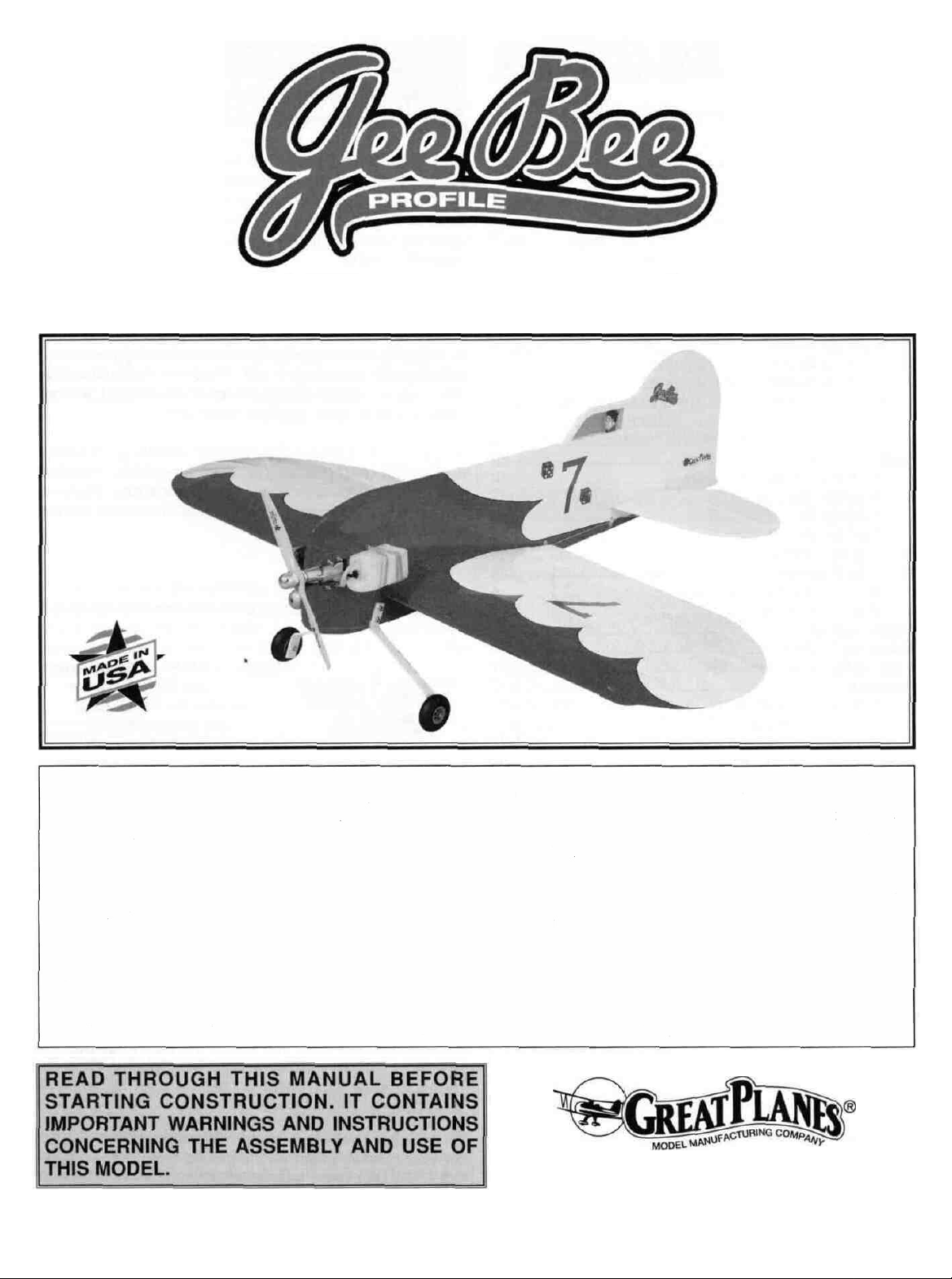
Your Gee Bee Profile is not a toy, but rather a
sophisticated, working model that functions very much like
an actual airplane. Because of its performance, the Gee
Bee Profile, if not assembled and operated correctly, could
possibly cause injury to yourself or spectators and
damage property.
To make your R/C modeling experience totally
enjoyable, we recommend that you get experienced,
knowledgeable help with assembly and during your
first flights. You'll learn faster and avoid risking your model
before you're truly ready to solo Your local hobby shop has
information about flying clubs in your area whose
membership includes qualified instructors.
You can also contact the national Academy of Model
Aeronautics (AMA), which has more than 2,500 chartered
clubs across the country. Through any one of them,
instructor training programs and insured newcomer training
are available.
Contact the AMA at the address or toll-free phone number below.
Academy of Model Aeronautics
5151 East Memorial Drive
Muncie, IN 47302-9252
Tele (800)435-9262
Fax (765) 741-0057
Or via the internet at: http //www modelaircraft.org
If you have been looking for a way to put the FUN back into
your Sunday flying, you have just found it The Gee Bee
Profile is a nimble little profile hot-dogger that assembles in
only a few hours and is easy on the budget It does not
require any special building or flying skill - just a few hand
tools and a little tail-dragger time. With its oversized control
surfaces it turns, loops and rolls in the blink of an eye, but
the thick, high lift airfoil and light wing loading allow the
plane to slow way down for gentle spot landings If
equipped with an engine like the OS 40 LA it's possible to
be airborne in a matter of feet, zip through three rolls, loop
on its own axis, then go into the "hover" mode while waiting
for your buddies to get off the ground What more can we
say? The Gee Bee Profile maximizes fun for minimal cost
and time!
2
Page 3
1 You must assemble the model according to the
instructions Do not alter or modify the model, as doing so
may result in an unsafe or unflyable model In a few cases
the instructions may differ slightly from the photos In those
instances the plans and written instructions should be
considered as correct.
2. Take time to build straight, true and strong.
3. Use an R/C radio system that is in first class condition,
and a correctly sized engine and components (fuel tank,
wheels, etc ) throughout your building process.
4. You must properly install all R/C and other components
so that the model operates correctly on the ground and in
the air
5 You must test the operation of the model before every
flight to insure that all equipment is operating, and you must
make certain that the model has remained structurally
sound Be sure to check clevises or other connectors often
and replace them if they show signs of wear or fatigue
NOTE: We, as the kit manufacturer, provide you with a
top quality kit and great instructions but ultimately the
quality of your finished model depends on how you build
it, therefore, we cannot in any way guarantee
the performance of your completed model, and no
representations are expressed or implied as to the
performance or safety of your completed model
Remember: Take your time and follow directions to end
up with a well-built model that is straight and true.
Please inspect all parts carefully before starting to build!
YOU CAN CONTACT US...
If any parts are missing, broken or defective, or if you
have any questions about building or flying this
airplane, please call us at (217) 398-8970. You can also
check our web site at www.greatplanes.com for the
latest Gee Bee updates, or e-mail your questions to
productsupport@greatplanes.com. If you are calling for
replacement parts, please reference the part numbers
and the kit identification number (stamped on the end of
the carton) and have them ready when calling.
Terns in parentheses (GPMQ4243) are suggested part
numbers recognized by distributors and hobby shops and
are listed for your ordering convenience GPM is the Great
Planes brand, TOP is the Top Flite brand, and HCA is the
Hobbico" brand.
D 4 Channel radio with 5 servos and a Y-harness
D 35-46 2-stroke or 40 - 52 4-stroke engine
D 6oz Fuel tank (GPMQ4102)
D (2) 2-1/2" Wheels (GPMQ4223)
D 1 "Tail wheel (GPMQ4241)
D (2) 3/32" Wheel collars (GPMQ4302)
D 12" Medium fuel tubing (GPMQ4131)
D (2) Rolls covering film
D 1/4" Foam Rubber (HCAQ1000)
These are the building supplies that are required We
recommend Great Planes Pro" CA and Epoxy glue
D 1 oz ThinCA(GPMR6002)
D 1 oz Medium CA (GPMR6008)
D 6-Minute Pro Epoxy (GPMR6045)
D 30-Minute Pro Epoxy (GPMR6047)
D Balsa filler (HCAR3401)
D Masking Tape (TOPR8018)
D Plan Protector (GPMR6167)
D IsopropyI Rubbing Alcohol (70%)
D Sanding block and sandpaper (coarse, medium, tine)
D Hobby knife (HCAR0105)
D #11 blades (HCAR0311)
D Single edge razor blades (HCAR0212)
D Razor Saw
D Razor Plane
D Electric drill
D Drill bits - 1/16", 5/64", 7/64", 1/8",
3/32",3/16"(HCAR0699)
D Small Phillips and flat blade screwdrivers
D Pliers with wire cutter
D Sealing Iron (COVR2700)
D Heat Gun (TOPR2000)
D T-Pins (HCAR5150)
D Straightedge with scale (HCAR0475)
D Cutting Mat (HCAR0456)
D Builders Triangle (HCAR0480)
3
Page 4
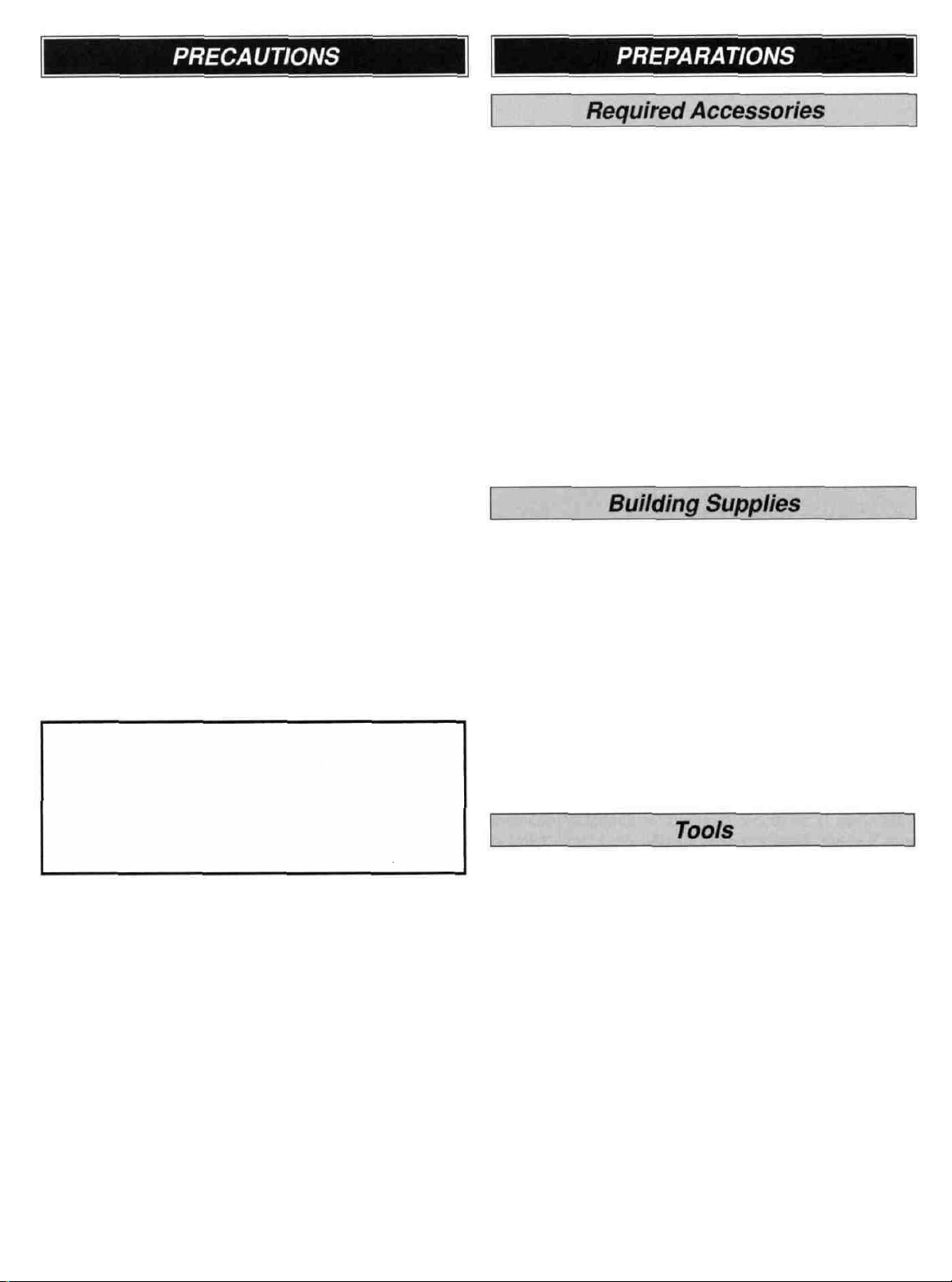
On our workbench, we have three 11" Great Planes
Easy-Touch Bar Sanders, equipped with 80, 150 and
220-grit sandpaper This setup is all that is required
for almost any sanding task We also keep some
320-grit wet-or-dry sandpaper handy for finish sanding
before covering
Elev = Elevator Fuse = Fuselage
LE = Leading Edge (front) LG = Landing Gear
Ply = Plywood Stab = Stabilizer
TE = Trailing Edge (rear) " = Inches
Balsa Basswood Plywood
Great Planes Easy-Touch Bar Sanders are made from
lightweight extruded aluminum and can be found at most
hobby shops They are available in five sizes - 5-1/2"
(GPMR6169) for those tight, hard-to-reach spots;
11" (GPMR6170) for most general purpose sanding, and
22" (GPMR6172), 33" (GPMR6174) and 44" (GPMR6176)
for long surfaces such as wing leading edges The
Easy-Touch Adhesive-Backed Sandpaper comes in
2" x 12' rolls of 80-gnt (GPMR6180), 150-grit (GPMR6183),
180-grit (GPMR6184) and 220-grit (GPMR6185) and an
assortment of 5-1/2" long strips (GPMR6189) for the short
bar sander The adhesive-backed sandpaper is easy to
apply and remove from your sanding bar when it's time
for replacement
This setup is all that is required for almost any sanding
task Custom sanding blocks can be made from balsa or
hardwood blocks and dowels for sanding difficult to
reach spots.
1 Unroll the plan sheet, then re-roll the plan inside-out to
make it lie flat.
2. Sort through the sticks and sheets grouping them by
size Masking tape can be used to bundle matching sheets
and sticks Using a felt tip or ball point pen lightly write the
part name or size on each piece or bundle Refer to the
parts list and plans for sizes and quantities Use the die-cut
patterns shown on page 5 to identify the die cut parts and
mark them before removing them from the sheet Save all
scraps If any of the die-cut parts are difficult to remove, do
not force them! Instead, cut around the parts with a hobby
knife or lightly sand the back of the sheet After removing
the die cut parts use your sanding block to lightly sand the
edges to remove any die-cutting irregularities
3 Work on a flat surface Cover the plan with waxed paper
or Great Planes Plan Protector material to prevent glue
from sticking to it.
4
Page 5
4. When instructed to test fit parts, this means DON'T USE
GLUE until you are satisfied that everything fits properly -
THEN glue the parts together if instructed to do so
5. Whenever the instructions tell you to glue pieces
together, CA or epoxy may be used When a specific type
of glue is required, the instructions will state the type of
glue that is highly recommended. When 30-mmute epoxy
is specified, it is highly recommended that you use only
30-minute (or slower) epoxy because you will need either
the working time and/or the additional strength
6 The easiest way to cut balsa sticks is with a single edge
razor blade or razor saw Position the stick over the plan,
mark its size, then cut the part on a piece of scrap lumber
A modeling miter box works well for cutting square corners
and 45° gussets.
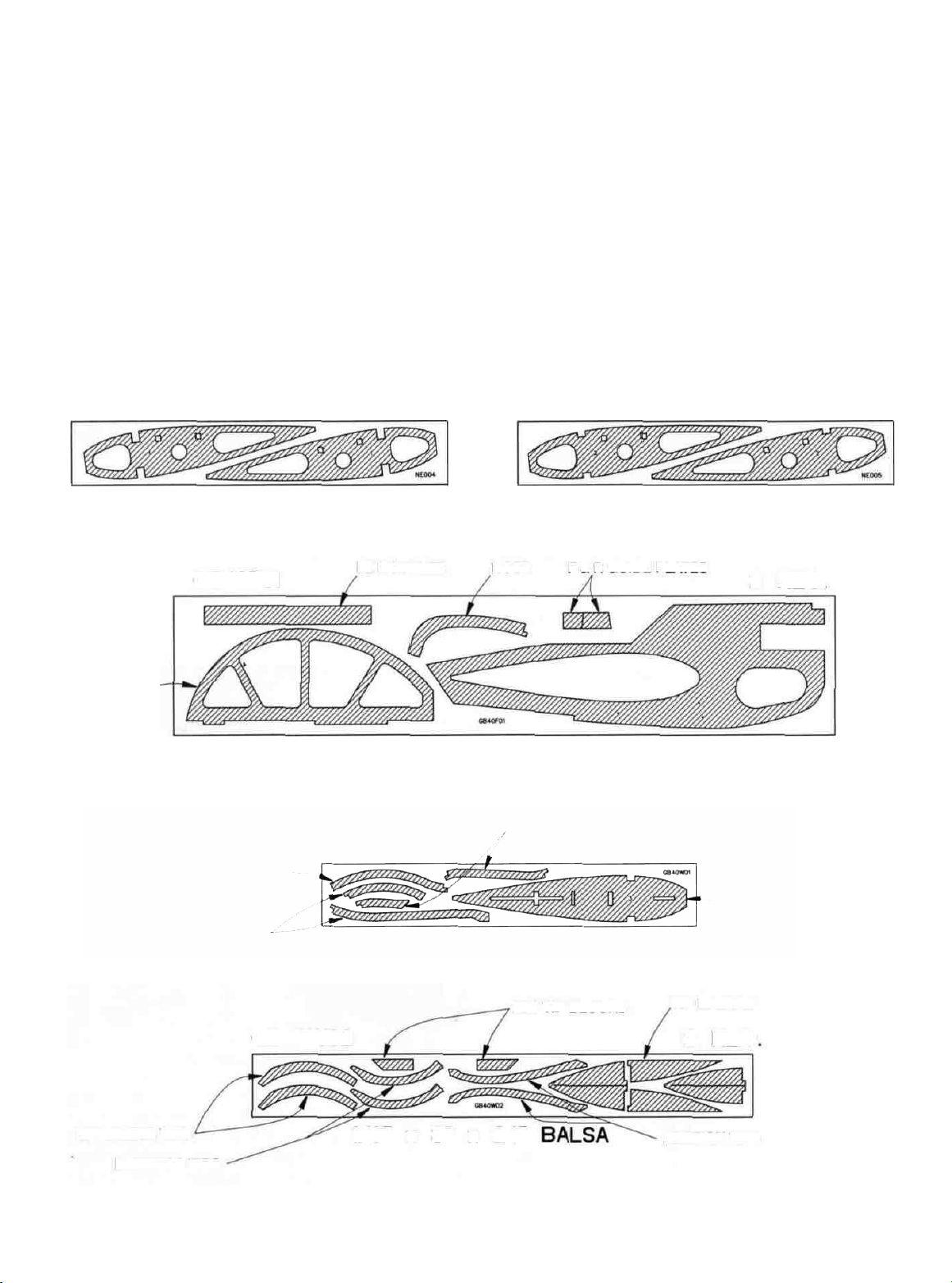
DIE-CUT PATTERNS
NE004 2 REQ. NE005 5 REQ.
3/32" X 3" X 18" BALSA
GB40F01
GB40W01
FIN
LE
RUDDER OUTER FRAME
3/32" X 3" X 18" BALSA
LE DOUBLER
NOSE
F & R GUIDE PLATES
1/8" x 6-5/8" x 31-3/4" PLY
CANOPY FRAME
2
REQ.
1/8" x 3" x 18" BALSA
TIP
2
RIB
REQ.
STABILIZER TIPS
ELEVATOR TIPS
GB40W02
AFT TIP BLOCKS
1/8" x 3" x 24" BALSA
5
TIP BRACES
2
REQ
AlLERON TIPS
Page 6
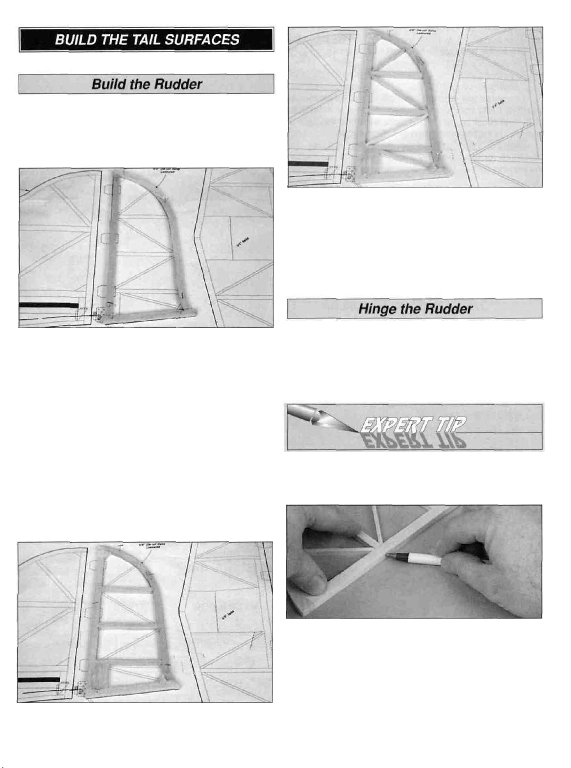
D 1. Glue together the pairs of die-cut 1/8" balsa rudder
TE'S to make 1/4" thick parts.
D 5. From a 1/8" x 1/4" x 30" balsa stick, cut and glue the
diagonal braces to the rudder frame.
D 6. Remove the rudder from your building board. Inspect
all the glue joints and add CA to any joints that don't look
strong. Sand the joints flush and the entire top and bottom
surface of the rudder flat and even. Be careful that you
don't sand any area too thin.
D 2. With the waxed paper or Plan Protector over the plan,
pin the rudder TE'S in position over the plan. Cut the
rudder outer frame from 1/4" x 3/8" x 30" balsa sticks.
Glue the outer frame and rudder frame together and pin it
in position over the plan. Use the plan or a straightedge as
a guide to make sure the rudder LE is straight as you glue
it in position.
D 3. From the 1/4" x 3/8" x 30" balsa stick, cut and glue
the two gussets and the control horn base to the
rudder frame.
D 1. Place the rudder over the plan and lightly mark the
hinge locations on the LE.
D 2. Mark the centerline on the rudder's LE using the
following centerline method.
HOW TO MARK A CENTERLINE
It's important that the hinges are centered and parallel to
the part you are hinging. The best way to start is by
accurately marking the hinge centerline.
D 4. From the 1/4" x 1/4" x 30" balsa stick, cut and glue
the rudder ribs to the rudder frame.
A. Lay the rudder and a ballpoint pen on a flat surface.
Mark a "test line" on the LE of the rudder.
B. Flip the rudder over and mark another line in the same
location as the first. If you see only one line, then it is on
center. Proceed and mark the centerline at each hinge
location. If you see two lines, use playing cards or business
cards to adjust the height of the pen until you can mark
the centerline.
6
Page 7
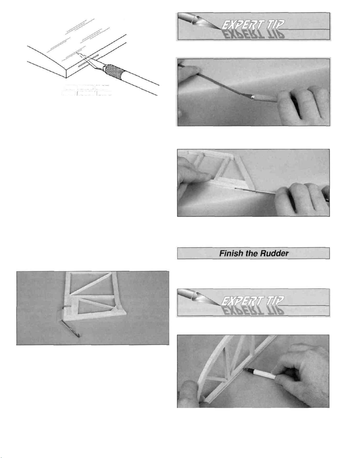
CUT HINGE SLOT
WITH HOBBY KNIFE
AND #11 BLADE
D 3. Cut the hinge slots in the rudder using a #11 blade.
Begin by carefully cutting a very shallow slit at the hinge
location to accurately establish the hinge slot. Make three
or four more cuts, going a little deeper each time. As you
cut, slide the knife from side to side until the slot has
reached the proper depth and width for the hinge.
D 4. Cut the 3/4" x 1" hinges for the rudder from the
supplied 2" x 9" hinge material. Use the hinge drawing on
the plan as a guide. Test fit the hinges into the rudder. Do
not glue the hinges at this time.
HOW TO CUT A GROOVE
A. Use a hobby knife to sharpen the inside of a piece of
1/8" brass tube. Roll the tube as you carve the end.
B. Use the sharpened tube to carefully gouge the leading
edge. You'll have to make several passes to make the
recess deep enough for the tailgear bearing.
D 5. Position the rudder over the plan and align the
tailgear assembly over the rudder. Mark the tailgear "arm"
location on the LE of the rudder. Drill a 7/64" hole, 3/4"
deep at the mark.
D 6. Cut a groove from the above hole to the bottom of the
rudder that will allow the nylon tailgear bearing to fit flush
with the LE of the rudder (see the following expert tip). Do
not glue the tailgear bearing in position at this time.
D 1. Refer to the Expert Tip that follows and shape the LE
of the rudder to a "V" shape as shown on the plan.
HOW TO BEVEL THE LEADING EDGE
A. Place the leading edge of the rudder on your work
surface and use your ballpoint pen to mark a "bevel to" line
on both sides about 1/8" high.
Page 8
B. Using the bevel to lines and the centerline as a guide,
make the "V" on the leading edge of the rudder with a razor
plane or your bar sander.
D 2. Draw a centerline on the TE and tip of the rudder.
Sand a radius on the edges as shown on the plan using the
centerline as a guide to keep the radius symmetrical.
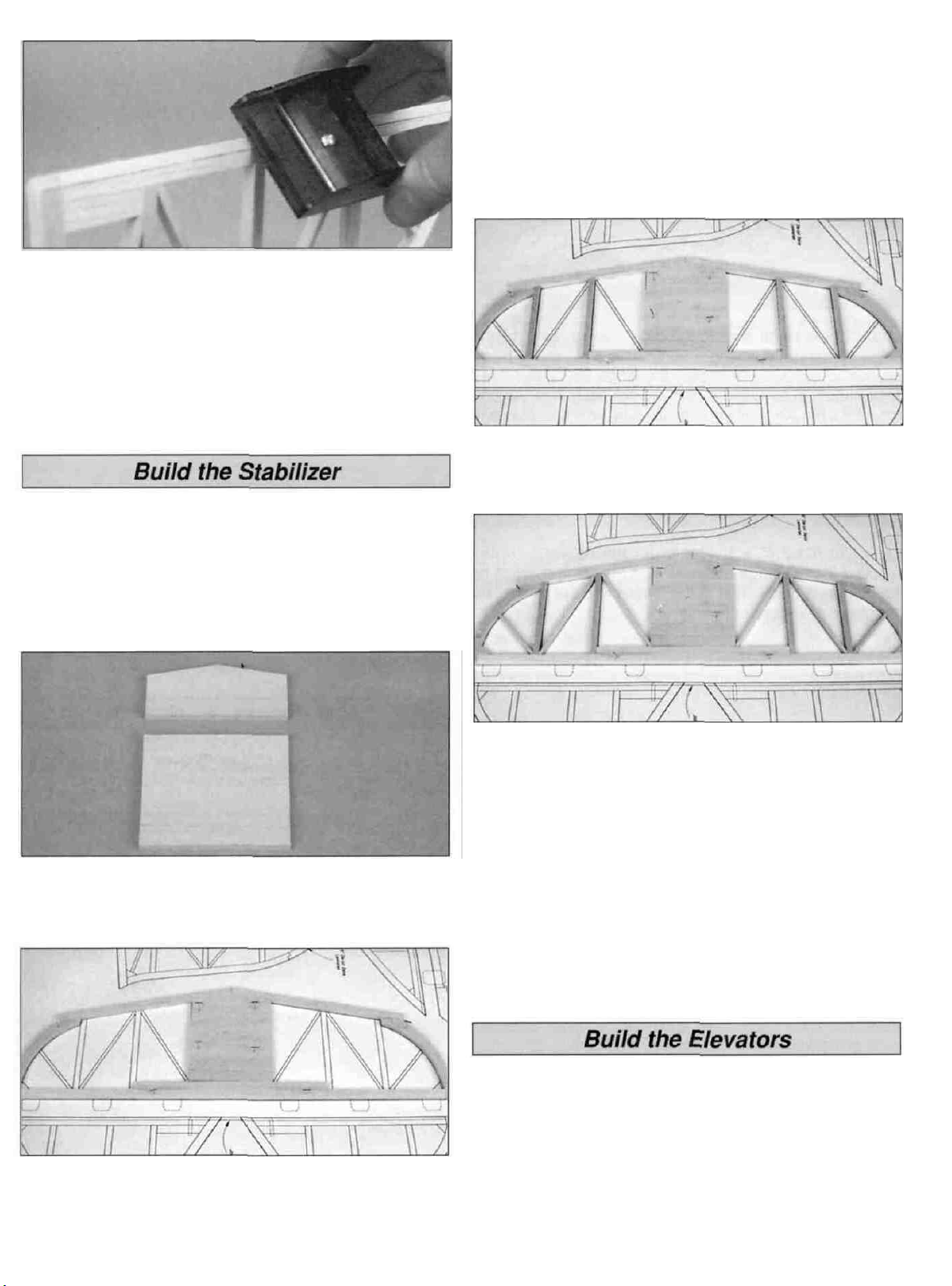
D 1. Pin the stabilizer and the elevator portion of the plan
to your building board. Cover this portion with waxed paper
or Plan Protector.
stab LE joiner, stab center and stab tips together. Use the
plan or a straightedge as a guide to make sure the stab TE
is straight as you glue it in position.
D 5. From a 1/4" x 3/8" x 30" balsa stick, cut and glue the
two gussets to the stab frame.
D 6. From the 1/4" x 1/4" x 30" balsa stick, cut and glue
the stab ribs to the stab frame.
D 2. Glue the pairs of die-cut 1/8" balsa stabilizer tips
together to make 1/4" thick parts.
D 3. Make the stabilizer LE joiner and stabilizer center
from a 1/4" x 3" x 7-1/2" balsa sheet. Use the plan for the
correct outline of the parts.
D 7. From a 1/8" x 1/4" x 30" balsa stick, cut and glue the
diagonal braces to the stab frame.
D 8. Remove the stab from your building board. Inspect all
the glue joints and add CA to any joints that don't look
strong. Sand the joints flush and the entire top and bottom
surface of the stab flat and even. Be careful that you don't
sand any area too thin.
D 4. Pin the stab LE joiner, stab center and stab tips in
position over the plan. Cut the stab outer frame from
1/4" x 3/8" x 30" balsa sticks. Glue the stab outer frame,
D 1. Pin the elevator plan to your building board and cover
it with waxed paper or Plan Protector.
D 2. Glue the pairs of die-cut 1/8" balsa elevator tips
together to make 1/4" thick parts.
8
Page 9

D 3. Pin the elevator tips in position over the plan. Cut the
elevator outer frame from 1/4" x 3/8" x 30" balsa sticks.
Glue the elevator outer frame and tips together. Make sure
each elevator LE is straight as you glue it in position. Glue
the elevator joiner wire doublers to the elevator LE'S.
D 4. From a 1/4" x 3/8" x 30" balsa stick, cut and glue the
two gussets to the elevator frame and tips.
D 5. From the 1/4" x 1/4" x 30" balsa stick, cut and glue
the elevator ribs to the elevator frame.
D 6. Remove the elevators from your building board.
Inspect all the glue joints and add CA to any joints that
don't look strong. Sand the joints flush and the entire top
and bottom surface of the stab flat and even. Be careful
that you don't sand any area too thin.
D 4. Position the stab and elevators over the plan and
mark the location of the elevator joiner on the elevators.
D 5. Drill a 3/32" pilot hole into the elevator LE, on the
centerline, at the torque rod marks. As you drill the holes,
keep the drill aligned with the top and bottom surfaces of
the elevator. Enlarge the holes with a 1/8" drill bit.
D 6. Cut a 1/8" groove in the leading edge of both
elevators to recess the joiner wire. Do not glue the joiner
wire in position at this time.
D 7. Remove the elevators from the stab. Mark the "bevel
to" lines and sand the LE of the elevators to a "V" as shown
on the plan.
D 1. Place the stab and elevator over their locations on the
plan and lightly mark the hinge locations on the TE of the
stab and LE of the elevator.
D 2. Make six 3/4" x 1" elevator hinges from the remaining
2" x 9" hinge material.
D 3. Mark the centerline of the hinges on the stab's TE and
elevator's LE. Cut the hinge slots and without using glue,
test fit the elevator on the stab.
D 8. Draw a centerline on the LE of the stab and the TE of
the elevators. Sand a radius on the LE of the stab and the
TE of the elevators, referring to the cross-section on the
plans as a guide.
This completes the stab and elevators. Put them aside for
now and let's move on to Building the Wing.
9
Page 10

NOTE: The wing is built as one piece, upside-down, over
the plan.
D 1. Pin the wing plan to the building board. Cover the
plan with waxed paper or Plan Protector.
D 2. Temporarily pin the 1/4" x 1" x 36" balsa stick over the
TE of the wing plan to create a temporary trailing edge
fixture. This fixture stick is used later to make the wing
leading edge. Cover the fixture with waxed paper or Plan
Protector. Pin the 1/8" x 3/8" x 36" balsa trailing edge to
the top edge.
D 4. Cut the 1/4" x 3/8" x 24" balsa spar doubler in half to
make two 12" sticks. Bevel both ends of spar doublers and
glue them to the wing spars where shown on the plan. Pin
the bottom spar assembly into position over the plan.
D 5. Glue the three die-cut 3/32" balsa #1 ribs onto the
bottom spar and trailing edge, perpendicular to the building
board. Important: Make sure that the 1/4" square holes for
the servo mounting rails are facing up as shown and that
the ribs are centered on the forward edge of the trailing edge.
TWO WARPED SPARS INSTALLED
THIS WAY WILL RESULT IN A
STRAIGHT WING
TWO WARPED SPARS INSTALLED
THIS WAY WILL RESULT IN A
WARPED WING
D 3. Match the 1/4" x 3/8" x 36" balsa wing spars so any
warps will counteract each other.
D 6. Glue the die-cut 1/8" ply leading edge doubler,
centered, on the front of the #1 ribs.
D 7. Cut two 7-7/8" long servo mounting rails from the
1/4" x 1/4" x 15" hardwood stick. Save the left-over pieces
for later use. Slide a servo mounting rail through the front
and back square holes as shown and glue them securely
into position.
10
Page 11

D 8. Glue all of the die-cut 3/32" balsa #2 and #3 ribs onto
the bottom spar and trailing edge. Once again make sure
all of the 1/4" square holes are facing up. From the
remaining 1/4" x 1/4" hardwood stick, cut and glue four 1/4"
square hardwood aileron servo mounting rails into the
square holes in the #2 ribs.
D 9. Center the 3/32" x 7/8" x 36" balsa sub-leading edge
on the forward edge of the #2 and #3 ribs and to the
leading edge doubler. Glue the sub-leading edge to the ribs
and doubler. Insert and glue the top wing spar into
notches in the ribs.
D 1. Glue the 1/16" x 7/8" x 36" balsa trailing edge
sheeting to the ribs and to the 1/8" x 3/8" balsa
trailing edge.
D 2. Use a long sanding block to sand the sub-leading
edge flush with the tops of all wing ribs.
D 3. Test fit the 1/16" x 3" x 36" LE wing sheet to the
wing. The aft edge of the wing sheeting should cover the
forward half of the wing spar. Remove any pins that are
holding the wing to the building board in front of the wing
spar. You may need to place weights on the wing to keep
the wing spars flat against the building board.
D 4. Apply medium CA to the top of the sub-leading edge
and the ribs from the wing spar forward. Working quickly,
center the LE wing sheet on the wing spar and press it
down against the ribs and the sub-leading edge. Use thin
CA to glue the wing sheet to the wing spar.
D 10. From a 1/16" x 3" x 30" balsa sheet, cut and glue
shear webs, perpendicular to the forward edge of the wing
spars. The shear webs must be glued securely to the
wing spars.
D 5. Use leftover 1/4" x 3/8" balsa sticks to make a frame
for the receiver hatch. The frame should be glued flush with
the top of the wing ribs.
11
Page 12

D 6. Temporarily position the servos on the servo rails.
From a 1/16" x 3" x 30" balsa sheet, cut sheeting to fit over
the center section and aileron bays. Use the plan to
determine the hatch location.
D 9. Remove the wing from the building board and turn it
over. Sand the sub-leading edge so that it's flush with the
tops of all ribs. Place the wing back on the trailing edge fixture.
D 10. Glue the second 1/16" x 3" x 36" leading edge sheet
to the ribs, beveled sub-leading edge and spar.
D 11. Glue the second 1/16" x 7/8" x 36" balsa trailing
edge sheet to the ribs and trailing edge.
D 7. From the 1/16" x 1/4" x 30" balsa sticks, cut and glue
the cap strips to the top of the wing ribs.
D 8. Trim the 1/16" x 3-3/8" x 5" plywood hatch cover to fit
the hatch frame as shown. Mark the location for the six
hatch screws. Place the hatch in position and drill a 1/16"
pilot hole through the hatch and hatch frame at each mark.
Countersink the six screw holes in the hatch. Test fit the
hatch to the wing using six #2 x 3/8" flat head screws.
Remove the hatch when you are satisfied with the fit. Apply
a couple of drops of thin CA to each screw hole in the hatch
frame to harden the balsa.
D 12. Cut, fit and glue the 1/16" x 3" balsa wing center
sheeting and 1/16" x 1/4" balsa cap strips to the wing ribs.
D 13. Sand the top and bottom leading edge sheeting until
it is flush with the front face of the sub-leading edge. Glue
the 1/4" x 1" x 36" balsa leading edge to the sub-leading
edge. You used this piece as a trailing edge fixture earlier
in the wing construction.
D 14. Trim and sand the LE to the shape as shown on
the plan.
12
Page 13

D 1. Sand the LE and TE, LE and TE sheeting, spars and
capstrips flush with rib #3 at both ends of the wing.
DD 2. Glue the die-cut 1/8" plywood wing tip
perpendicular to rib #3.
DD 6. Sand the forward and aft tip blocks to shape.
D 7. Go back to step 2 and install the other wing tip.
D 1. Glue together the pairs of die-cut 1/8" balsa aileron
tips to make 1/4" thick parts. Sand them to shape as
shown on the plan.
DD 3. Glue three die-cut 1/8" balsa wing tip braces to
the top and three to the bottom of the plywood wing tip
and rib #3.
DD 4. Sand the top of the wing tip braces flush with the
capstrips on rib #3.
DD 5. Glue the die-cut 1/8" balsa aft tip blocks on the
top and bottom of the aft edge of the plywood wing tip.
From a 1/2" x 1/2" x 6" balsa stick, cut and glue forward tip
blocks on the top and bottom of the forward edge of
wing tip.
DD 2. With the waxed paper or Plan Protector still
positioned over the plan, pin an aileron tip in position. Cut
the aileron outer frame from 1/4" x 1/4" x 30" and 1/4" x
3/8" x 30" balsa sticks. Glue the outer frame and aileron
tips together and pin it in position over the plan. Make sure
the aileron LE is straight as you glue and pin it in position.
DD 3. From the 1/4" x 1/4" x 30" balsa stick, cut and glue
the aileron ribs to the aileron frame.
DD 4. From the 1/4" x 3/8" x 30" balsa stick, cut and glue
the two gussets and the control horn base to the
aileron frame.
13
Page 14

DD 5. Cut the diagonal braces from a 1/8" x 1/4" x 30"
balsa stick. Glue the braces in position.
DD 6. Remove the aileron from your building board.
Inspect all the glue joints and add CA to any joints that
don't look strong. Sand the joints flush and the entire top
and bottom surface of the aileron flat and even. Be careful
that you don't sand any area too thin.
D 7. Go back to step 2 and build the second aileron.
D 1. Place the ailerons and wing over their locations on
the plan and lightly mark the hinge locations on the TE of
the wing and LE of the aileron.
D 2. Use the leftover hinge material to make eight
3/4" x 1" aileron hinges.
D 1. Make 1/4" thick parts by gluing together the pairs of
die-cut 1/8" plywood, nose, front and rear guide plates
and die-cut 1/8" balsa canopy frame and fin LE. Use 6minute epoxy to glue the two die-cut 1/8" plywood fuselage
bodies together. Apply epoxy to one side of the fuse body.
Lightly clamp the second side to the first. If your fuse sides
are warped, you will need to twist the fuse body in the
opposite direction of the warp as the epoxy cures. This
process will take some patience, but will produce a straight
fuse body. Sand the parts as needed to match the plan.
D 3. Mark the centerline of the hinges on the wing's TE
and aileron's LE using the centerline method. Cut the hinge
slots and without using glue, test fit the ailerons on
the wing.
D 4. Remove the ailerons from the wing. Mark the "bevel
to" lines and sand the LE of the ailerons to a "V" as shown
on the plan.
D 5. Sand a slight radius on the wing tips and the TE of
the ailerons.
D 2. With the waxed paper or Plan Protector positioned
over the fuse plan, pin the fuse body, nose, front and rear
guide plates, canopy frame and fin LE in position over the
plan. Cut the fuse outer frame from 1/4" x 1/4" x 30" and
1/4" x 3/8" x 30" balsa sticks. Glue the outer frame and
plywood parts together and pin it in position over the plan.
D 3. Finish assembling the interior framework from the
1/4" x 1/4" and 1/4" x 3/8" balsa sticks. Glue 1/4" gussets in
the corners.
14
Page 15

D 4 Remove the fuse frame from your building board and
sand both sides flat Be careful that you don't sand any
area too thin.
D 1 Drill a 3/16" hole at the punch marks for the landing
gear and a 1/8" hole at the balance point.
D 4 Glue the fuse skins to the right side of the fuse frame.
Do not glue the fuse skin to the fuse frame at the engine
rail or landing gear locations.
D 5. Use a 3/16" and 1/8" drill bit to drill through the fuse
skin at the landing gear mounting holes and balance point.
Make sure to back the skin with a piece of leftover wood to
prevent the balsa skin from splitting when the drill bit exits.
Trim and sand the fuse skin flush with the outside edge of
the fuse frame and the center of the wing and stab "cutout " Keep the sheeting you cut from the wing opening to
use as a template when covering the fuse To dress-up
your Gee Bee Profile, the cockpit center can also be
trimmed out.
D 2 Place two of the 1/16" x 1/2" x 6" plywood engine
rails in position on each side of the engine opening and the
landing gear in position on the bottom of the fuse frame
Trace around the engine rails and landing gear Repeat the
process on the other side of the fuse.
D 6. Use the remaining three sheets of 1/16" x 3" x 36"
and the 1/16" x 3 x 12" to sheet the left side of the fuselage.
Trim and drill the skin as before.
D 7. Place two of the plywood engine rails in position on
each side of the engine opening and the landing gear at the
bottom of the fuse Again, trace around them Repeat the
process on the other side of the fuse Carefully trim the
balsa skin from the engine rail and landing gear area.
D 3. To make the fuse skins, edge glue three 1/16" x 3" x
36" balsa sheets together to make a skin 1/16" x 9" x 36".
Cut a 1/16" x 3" x 24" sheet in half and edge glue one 12"
piece to the three sheets as shown Sand the sheets flat
with fresh 220-grit sandpaper.
D 8 Use 30-minute epoxy to glue the engine rails to both
sides of the plywood fuse body Use clamps or weights to
hold the rails tightly in position.
D 9 Sand a slight radius on the edges of the fuse to
remove the sharp edge.
15
Page 16

D 1. Draw a centerline from leading edge to trailing edge
on the top of the wing and stab. Draw a parallel line 3/16"
on each side of the centerlines. Insert the wing in the fuse.
D 4. Center the stab in the stab slot using the centerline
you drew in step #1. View the airplane from the aft end. If
the stab tips are not an equal distance above the wing,
carefully sand the high side of the stab slot until the stab is
aligned. With the stab positioned at the forward end of the
stab slot, check that the stab tips measure the same
distance from the center of the nose.
D 5. Use 30-minute epoxy to glue the stab to the fuse.
After the epoxy has cured, fill any gaps with a mixture of
microballoons and epoxy.
D 6. Position the rudder on the TE of the fuse and mark
the hinge and tailgear bearing locations. Carefully cut hinge
and tailgear bearing slots in the TE of the fuse. Test fit the
rudder on the fuse.
D 7. Attach the landing gear to the fuse using two 6-32 x
3/4" cap head screws, two #6 washers and two 6-32
lock nuts.
A
D 2, Carefully center the wing in the fuse. Check that the
wing tips measure the same distance from the center of the
tail and that the wing is perpendicular to the fuse sides.
I—I 3. Use 30-minute epoxy to glue the wing to the fuse.
Check that the wing is centered and perpendicular to the
fuse. After the epoxy has cured, fill any gaps with
microballoons and epoxy.
A
D1 1. Install a propeller on your engine. Center the engine
between the engine rails with the back of the propeller
approximately 3/32" from the front of the fuselage.
D 2. Mark the engine mounting holes on the engine rails.
Drill four 1/8" holes through the engine rails at the marks.
D 3. Use two #4 washers under the two front holes
between the engine and the rails. This will provide the 2
degrees of right thrust required. Secure the engine to the
rails with four 4-40 x 1" pan head bolts, 4-40 locknuts
and #4 washers.
16
Page 17

Do not confuse this procedure with "checking the C.G." that
will be discussed later in the manual
Now that the model is nearly completed, you should
balance it laterally (side-to-side) An airplane that is laterally
balanced will track better during acrobatic maneuvers
Here's how
1 Temporarily attach the elevators, rudder, engine and
landing gear Lift the model by the propeller shaft and the
bottom of the fuse near the rudder. This will require an
assistant Do this several times
2 The wing that consistently drops indicates the heavy
side Balance the model by adding weight to the opposite
wing tip.
Cover the model with Top Flite MonoKote film, using the
suggested covering sequence that follows Before you
cover the fuselage first apply 1/4" wide strips of MonoKote
film in the corners where the stab and wing meet the
fuselage Proceed to cover the stab with pre-cut pieces that
meet in the corners and overlap the 1/4" strips Never cut
the covering on the stab and fin after it has been applied
except around the leading and trailing edges and the tips
Modelers who do this may cut through the covering and
into the stab This will weaken the structure to a point
where it may fail during flight.
Some modelers prefer to cover the top and bottom of the
ailerons with one strip of MonoKote film This is done by
covering the bottom first, then wrapping the MonoKote film
up over the leading edge
We used Top Flite MonoKote White (TOPQ0204), Missile
Red (TOPQ0218) and Black (TOPQ0208) to cover our
Gee Bee Profile
D 1 Remove the engine, landing gear and any other
hardware you may have installed.
D 2 Most of the model should be rough-sanded by now,
with all edges sanded and rounded following the cross-
section views on the plans Fill all dents, seams, low spots
and notches with HobbyLite" balsa colored filler
Fuselage and Tail:
1. 1/4" strips at the stab and wing as described
2. Fuselage right side (use the "balsa template' made
on page 15 to cut out the wing opening)
3. Fuselage left side (Use the template here also)
4. Fin TE, followed by stab TE
5. Stab bottom, followed by top
6. Rudder Leading Edge
7. Rudder, followed by the left side
8. Elevator LE
9. Elevator bottoms, followed by the top
Wing:
D 3 After the filler has dried use progressively finer
grades of sandpaper to even and smooth all the edges,
seams and surfaces Remove all the balsa dust from the
model with compressed air or a vacuum with a brush and a
tack cloth
1. T E of wing
2. Bottom right, followed by the left wing panel
3. Top right, followed by the left wing panel
4. Aileron LE, followed by the bottom and top
17
Page 18

D 1. Starting with the elevators and stab, cut the covering
from the hinge slots
INSTALLING CA HINGES
The hinge material supplied in this kit consists of a 3 layer
lamination of mylar and polyester It is specially made for
the purpose of hinging model airplane control surfaces
Properly installed, this type of hinge provides the best
combination of strength, durability and ease of installation.
We trust even our best show models to these hinges, but it
is essential to install them correctly Please read the
following instructions and follow them carefully to obtain the
best results These instructions may be used to effectively
install any of the various brands of CA hinges.
The most common mistake made by modelers when
installing this type of hinge is not applying a sufficient
amount of glue to fully secure the hinge over its entire
surface area, or, the hinge slots are very tight, restricting
the
flow
of
CA to the
back
of
the hinges This results in
hinges that are only "tack glued" approximately 1/8" to 1/4"
into the hinge slots The following technique has been
developed to help ensure thorough and secure gluing.
It is best to leave a very slight hinge gap, rather than
closing it up tight, to help prevent the CA from wicking
along the hinge line Make sure the control surfaces will
deflect to the recommended throws without binding If you
have cut your hinge slots too deep, the hinges may slide in
too far, leaving only a small portion of the hinge in the
control surface To avoid this, you may insert a small pin
through the center of each hinge before installing This pin
will keep the hinge centered while you install the control
surfaces
D 2 Clean the elevator joiner wire with alcohol and a
paper towel to remove any oil residue
D 3. Glue the joiner wire in the elevators with 6-minute
epoxy Before the epoxy cures, tape a flat stick to the left
and right side of the stab and to the elevators This will
ensure that both elevators are even.
ASSEMBLE THEN APPLY 6 DROPS
OF THIN CA TO CENTER
OF HINGE ON BOTH SIDES
Drill a 3/32" hole, 1/2" deep, in the center of the hinge slot
If you use a Dremel MultiPro" for this task, it will result in a
cleaner hole than if you use a slower speed drill Drilling the
hole will twist some of the wood fibers into the slot, making
it difficult to insert the hinge, so you should reinsert the
knife blade, working it back and forth a few times to clean
out the slot.
D 4. Apply 6 drops of thin CA adhesive to both sides of
each hinge Allow a few seconds between drops for the CA
to wick into the slot.
D 5 Install the ailerons with their hinges repeating the
gluing technique described previously.
D 6 Cut a slot in the TE of the fin for the tailwheel bracket
nylon bearing.
D 7 Lightly coat the tailwheel wire with petroleum jelly
where it enters the nylon bearing This will prevent the wire
from becoming glued to the bearing
D 8 Pack the tailwheel bracket hole in the rudder and the
slot in the TE of the fin with 30 minute epoxy Install the
rudder with its hinges Repeat the gluing technique
described previously and allow the epoxy to cure.
18
Page 19

D 1. Assemble your 6 oz. fuel tank per the manufacturer's
instructions. Open the three "closed loop" eyelets slightly to
make hooks. Locate the position of the three hooks and
thread them into the left side of the fuselage. Place a piece
of 1/4" foam between the fuselage side and the tank. We
recommend you use 3 rubber bands to secure the tank to
the aircraft.
D 2. Reinstall the engine. Connect fuel tubes to the fuel
pick-up fitting and the pressure fitting, on the fuel tank.
D 3. Connect the fuel pick-up tube to the carburetor.
Connect the pressure tube to the muffler.
D 1. Install a 1" tail wheel (not included) on the tailwheel
wire. Secure the tail wheel with a 3/32" wheel collar and
4-40 x 1/8" set screw.
D 1. Install the elevator, rudder, throttle and two aileron
servos in the wing. Space the rudder, elevator and throttle
servos so that their servo arms do not interfere with each
other or the fuselage side. NOTE: The servo arms in the
picture have been painted for clarity.
D 2. Wrap the receiver battery in foam padding and insert
it in the front of the radio compartment. Plug the servos into
the receiver. Wrap the receiver in foam padding and place it
behind the battery at the front of the radio compartment.
Install the receiver switch in the hatch cover and plug the
receiver battery into the receiver switch.
D 2. Reinstall the landing gear to the fuse using 6-32 x 3/4"
cap head bolts and lock nuts. Insert a 8-32 x 1-1/4" socket
cap head bolt through each 2-1/2" wheel (not included).
Screw an 8-32 nut onto each bolt. Do not tighten the nuts
completely. The wheels must rotate freely. Insert the cap
head bolt through the landing gear, apply thread lock to the
bolt threads and secure the bolt to the landing gear with a
second 8-32 nut.
D 3. Slide a silicone retainer over the threaded end of
two 36" threaded pushrods. Thread a nylon clevis 14
turns onto each pushrod. Connect the clevises to one large
and one small nylon control horn. NOTE: The control
horns in the picture have been painted for clarity.
19
Page 20

RIGHT WRONG
D 4. Position the large control horn on the elevator and the
small control horn on the rudder. Align the horns with the
hinge line, as shown in the sketch and the plan. Mark the
location of the mounting holes and drill a 3/32" hole at the
marks. Mount the control horns on the elevator and
rudder with the backing plate and 2-56 x 1/2" screws.
D 5. Mark the location on both sides of the fuse for the
nylon pushrod guides. Refer to the fuse plan for the
proper location. NOTE: The guides on the left side are offset from the guides on the right side.
D 8. Make a 90° bend at the marks you made. Cut the
pushrods 3/8" above the bend and connect the pushrods to
the servos with nylon faslinks.
NOTE: If necessary, enlarge the holes in the servo arms
with a 5/64" drill bit (or a #48 drill bit for precision).
D 6. Bend both pushrods so that they are positioned next
to the fuse sides. Make sure the bends are aft of the aft
pushrod guide location.
D 7. With the radio switched on and the servos centered,
position the elevator and rudder to neutral. Mark the
pushrods where they cross the mounting holes in the
servo arms.
D 9. Position the nylon pushrod guides on the sides of
the fuse, at the marks made in step 5. Mark the location of
the guide mounting holes and drill a 1/16" hole at each
mark. Attach the guides to the fuse sides with #2 x 3/8"
sheet metal screws.
D 10. Slide a silicone retainer over the threaded end of a
12" threaded pushrod. Thread a nylon clevis 14 turns
onto the pushrod. Bend and cut the pushrod to fit your
engine installation, making sure that the muffler does not
interfere with the pushrod.
20
Page 21

U 11. Install the Screw-Lock Pushrod Connector in the
throttle servo arm. Slide the throttle pushrod through the
pushrod connector. With the radio switched on, adjust the
throttle trim to high. Move the throttle stick to full throttle
and move the throttle arm on the carburetor to full open.
Tighten the 4-40 set screw in the pushrod connector.
Check the movement of the throttle. The carburetor should
not close completely when the throttle stick is moved to low.
The carburetor should close completely only when the
throttle trim is moved to low.
D 2. Or, the covering can be cut from over the cockpit
opening. Cut the drawing of the pilot bust from the plan
sheet and glue it to a leftover piece of plywood. Trim the
plywood to the outline of the bust. Felt tip markers or paint
can be used to color the bust. Stick a pin in the bottom of
the bust and cut the end of the pin off. Insert the bust in the
cockpit and glue in place. Clear MonoKote or thin butyrate
can be placed over the cockpit to simulate windows.
4-CHANNEL RADIO SETUP
(STANDARD MODE 2)
ELEVATOR MOVES UP
D 12. Install the 12" aileron pushrods following the same
procedure used to install the elevator pushrod.
D 1. The cockpit can be finished in two different styles. If
you left the sheeting over the cockpit area, the canopy
decal can be cut from the decal sheet and placed over
the cockpit area.
RIGHT AILERON MOVES UP
LEFT AILERON MOVES DOWN
RUDDER MOVES RIGHT
NOSE WHEEL TURNS RIGHT
CARBURETOR WIDE OPEN
The throws are measured at the widest part of the
elevators, rudder and ailerons. Adjust the position of the
pushrods at the servo horns to control the amount of throw.
You may also use the ATV'S if your transmitter has them but
the mechanical linkages should still be set so the ATV'S are
near 100% for the best servo resolution (smoothest, most
proportional movement).
21
Page 22

We recommend the following control surface throws:
Elevator: High Rate
7/8" up [22.2mm]
7/8" down [22.2mm]
Rudder: 2" left [50.8mm]
2" right [50.8mm]
Ailerons: 1" up [25.4mm]
1" down [25.4mm]
Low Rate
5/8" up [15.8mm]
5/8" down [15.8mm]
5/8" left [15.8mm]
5/8" right [15.8mm]
3/4" up [19mm]
3/4" down [19mm]
NOTE: If your radio does not have dual rates, we
recommend setting the throws at the low rate setting. The
high rate throws are tor "hot dog" flying.
We added approximately 20% exponential to all control
surfaces This reduces the sensitivity of the control
surfaces at the neutral position.
NOTE: The balance and control throws for the Gee Bee
Profile have been extensively tested This chart indicates
the settings at which the Gee Bee Profile flies best Please
set up your model to the specifications listed above If, after
you become comfortable with your Gee Bee Profile, you
would like to adjust the throws to suit your tastes, that's
fine Too much throw can force the plane into a stall or snap
roll, so remember, "more is not always better."
the balance up to 3/8"[9.5mm] forward or backward to
change its flying characteristics Moving the balance
forward may improve the smoothness and stability, but the
model may then require more speed for takeoff and may
become more difficult to slow for landing Moving the
balance aft makes the model more agile with a lighter,
snappier "feel," and often improves knife-edge capabilities
In any case, please start at the location we recommend Do
not at any time balance your model outside the
recommended range.
Q 2 With all parts of the model installed (ready-to-fly) and
an empty fuel tank, lift the model at the balance point If the
tail drops, the model is "tail heavy" and you must add
weight to the nose to balance the model If the nose drops,
it is "nose heavy and you must add weight to the tail to
balance the model.
NOTE: Nose weight may be easily installed by using a
"spinner weight" Tail weight may be added by using Great
Planes (GPMQ4485) "stick-on" lead weights.
NOTE: This section is VERY important and must NOT be
omitted' A model that is not properly balanced will be
unstable and possibly unflyable.
D 1 The balancing point (C.G.) is located 3-7/8"[98.4mm]
back from the leading edge of the wing Hang the Gee Bee
Profile by a string threaded through the balance hole on the
bottom of the model This is the balance point at which your
model should balance for your first flights After initial trim
flights and when you become more acquainted with your
Gee Bee Profile, you may wish to experiment by shifting
If possible, first attempt to balance the model by changing
the position of the receiver battery If you are unable to
obtain good balance by doing so, then it will be necessary
to add weight to the nose or tail to achieve the proper
balance point.
At this time, check all connections including servo horn
screws, clevises, servo cords and extensions Make sure
you have installed the nylon retainer on the Screw-Lock
Pushrod Connector and the silicone retainers on all
the clevises.
Follow the battery charging procedures in your radio
instruction manual You should always charge your
transmitter and receiver batteries the night before you go
flying, and at other times as recommended by the
radio manufacturer.
22
Page 23

Balance your propellers carefully before flying An
unbalanced prop is the single most significant cause of
vibration Not only will engine mounting screws and bolts
vibrate out, possibly with disastrous effect but vibration will
also damage your radio receiver and battery Vibration may
cause your fuel to foam, which will, in turn cause your
engine to run lean or quit.
least 6 miles away from houses, buildings and streets and
any other R/C radio operation like R/C boat and R/C cars A
schoolyard may look inviting but is too close to people,
power lines and possible radio interference
Inspect your radio installation and confirm that all the
control surfaces respond correctly to the transmitter inputs
The engine operation must also be checked by confirming
that the engine idles reliably, transitions smoothly and
rapidly to full power and maintains full power indefinitely
The engine must be "broken-in" on the ground by running it
for at least two tanks of fuel Follow the engine
manufacturer s recommendations for break-in Make sure
all screws remain tight, that the hinges are secure and that
the prop is on tight.
We use a Top Flite Precision Magnetic Prop Balancer
(TOPQ5700) in the workshop and keep a Great Planes
Finger Balancer (GPMQ5000) in our flight box
Since you have chosen the Gee Bee Profile, we assume
that you are an experienced modeler Therefore, you
should already know about AMA chartered flying fields and
other safe places to fly If for some reason you are a
relatively inexperienced modeler and have not been
informed, we strongly suggest that the best place to fly is
an AMA chartered club field Ask the AMA or your local
hobby shop dealer if there is a club in your area and join
Club fields are set up for R/C flying and that makes your
outing safer and more enjoyable The AMA address and
telephone number are in the front of this manual If a club
and flying site are not available, find a large, grassy area at
Whenever you go to the flying field check the operational
range of the radio before the first flight of the day First,
make sure no one else is on your frequency (channel) With
your transmitter on, you should be able to walk at least 100
feet away from the model and still have control While you
work the controls, have a helper stand by your model and
tell you what the control surfaces are doing Repeat this
with the engine running at various speeds with a helper
holding the model If the control surfaces are not always
responding correctly, do not fly Find and correct the
problem first Look for loose servo connections or
corrosion, loose bolts that may cause vibration, a defective
on/off switch, low battery voltage or a defective receiver
battery, a damaged receiver antenna, or a receiver crystal
that may have been damaged from a previous crash
NOTE: Failure to follow these safety precautions may result
in severe injury to yourself and others
Keep all engine fuel in a safe place away from high heat,
sparks or flames, as fuel is very flammable Do not smoke
near the engine or fuel, and remember that the engine
exhaust gives off a great deal of deadly carbon monoxide.
Do Not run the engine in a closed room or garage
23
Page 24

Get help from an experienced pilot when learning to
operate engines.
Use safety glasses when starting or running engines.
Do not run the engine in an area of loose gravel or sand;
the propeller may throw such material in your face or eyes.
Keep these items away from the prop loose clothing, shirts
sleeves, ties, scarfs, long hair or loose objects such as
pencils or screwdrivers that may fall out of shirt or jacket
pockets into the prop.
3. Where established, I will abide by the safety rules for the
flying site I use and I will not willfully and deliberately fly my
models in a careless, reckless and/or dangerous manner.
4 I will not fly my model unless it is identified with my name
and address or AMA number, on or in the model
5. I will not operate models with pyrotechnics (any device
that explodes, burns, or propels a projectile or any kind)
1.I will have completed a successful radio equipment ground
check before the first flight of a new or repaired model
Use a "chicken stick" or electric starter to start the engine
Do not use your fingers to flip the propeller Make certain
the glow plug clip or connector is secure so that it will not
pop off or otherwise get into the running propeller.
Make all engine adjustments from behind the rotating propeller.
The engine gets hot' Do not touch it during or right after
operation Make sure fuel lines are in good condition so fuel
will not leak onto a hot engine, causing a fire.
To stop a glow engine, cut off the fuel supply by closing off
the fuel line or following the engine manufacturer's
recommendations Do not Use hands, fingers or any other
body part to try to stop the engine Do not throw anything
into the propeller of a running engine
Read and abide by the following Academy of Model
Aeronautics Official Safely Code.
1. I will not fly my model aircraft in sanctioned events, air
shows, or model flying demonstrations until it has been
proven to be airworthy by having been previously
successfully flight tested.
2. I will not fly my model aircraft higher that approximately
400 feet within 3 miles of an airport without notifying the
airport operator I will give right of way to and avoid flying in
the proximity of full-scale aircraft Where necessary an
observer shall be used to supervise flying to avoid having
models fly in the proximity of full-scale aircraft
2 I will not fly my model aircraft in the presence of
spectators until I become a qualified flier, unless assisted
by an experienced helper.
3. I will perform my initial turn after takeoff away from the pit
or spectator areas and I will not thereafter fly over pit or
spectator areas, unless beyond my control.
4. I will operate my model using only radio control frequencies
currently allowed by the Federal Communications Commission
Caution: (THIS APPLIES TO ALL R/C AIRPLANES)
If, while flying, you notice any unusual sounds, such as
a low-pitched "buzz", this may indicate control surface
"flutter" Because flutter can quickly destroy components
or your airplane, any time you detect flutter you must
immediately cut the throttle and land the airplane' Check
all servo grommets for deterioration (this may indicate
which surface fluttered) and make sure all pushrod
linkages are slop-free If it fluttered once, it will probably
flutter again under similar circumstances unless you can
eliminate the slop or flexing in the linkages Here are
some things which can result in flutter Excessive hinge
gap, Not mounting control horns solidly, Sloppy fit of
clevis pin in horn, elasticity present in flexible plastic
pushrods, Side-play of pushrods in guide tube caused
by tight bends, sloppy fit of control rods in servo horns,
insufficient glue used when gluing in torque rods,
Excessive flexing of aileron, caused by using too soft
balsa, Excessive play" or "backlash" in servo gears, and
insecure servo mounting
The Great Planes Gee Bee Profile is a real-flying plane that
flies smoothly and predictably The Gee Bee Profile does
not, however, possess the self-recovery characteristics of a
primary R/C trainer and should only be flown by
experienced R/C Pilots.
24
Page 25

BUILDING NOTES
Kit Purchased Date:
Where Purchased:
Date Construction Started:
Date Construction Finished:
Finished Weight:
Date of First Flight:
FLIGHT LOG
26
Page 26

GPMR8500
GPMR2400
Bench Topper holds the inexpensive answer to building
supply storage and organization hassles It assembles quickly
into a 155" long x 7 25" high x 5 25" deep caddy that fits
comfortably on any bench—or can be mounted conveniently
on a wall The lite ply parts simply CA together You can even
customize its top center section to suit your special storage
needs'
Great Planes Dazzler™
Nothing unleashes your wild
side like the Dazzler. Big on
performance and low on frills,
it's perfect for those times when
all you want is to LET 'ER RIP!
With just a bushing .40, the
Dazzler dances through extreme maneuvers.
Its nearly symmetrical airfoil and oversized
control surfaces supply all the snap you need
for rocketing rolls and wild aerobatics. The
dual aileron servo set-up minimizes flutter and
slashes response time to the bone. You'll
need only one or two days to frame up the
Dazzler's lightweight, all-wood parts—thanks
to its basic box fuselage and simple stick
construction. The entire kit can be built in as
little as two weekends!
Accurate balancing makes trainers more stable, low-wing
aerobats more agile, and pylon planes faster than ever The
innovative C.G. Machine" makes it easy to achieve optimum
balance without measuring, without marking, and without the errors that fingertip balancing can cause You'll quickly be able
to pinpoint your planes exact center of gravity Then, you'll
know at a glance whether weight should be added, removed or
relocated The C G Machine works with kits and ARF models
of any size and wingspan Its slanted wire balancing posts
support models weighing up to 40 pounds
GPMA0480
Wingspan: 48 in (1220 mm)
Wing Area: 578 sq in (37 3 sq dm)
Weight: 3 5-4lb (1590-1810 g)
Length: 43 in (1170 mm)
Radio Required: 4-channel with 5 servos
Engine Required: 2-stroke 32- 40 cu in (5 3-6 5 cc)
4-stroke 40-.52 cu in (6 5-8 5 cc)
27
Page 27

TWO-VIEW DRAWING
 Loading...