

Page 1
Great Planes®Model Manufacturing Co. guarantees this kit to be free from defects in both material and workmanship at the date of
purchase.This warranty does not cover any component parts damaged by use or modification. In no case shall Great Planes’ liability
exceed the original cost of the purchased kit. Further, Great Planes reserves the right to change or modify this warranty without notice.
In that Great Planes has no control over the final assembly or material used for final assembly, no liability shall be assumed nor
accepted for any damage resulting from the use by the user of the final user-assemb led product.By the act of using the user-assembled
product, the user accepts all resulting liability.
If the buyer is not prepared to accept the liability associated with the use of this product, the buyer is advised to return this
kit immediately in new and unused condition to the place of purchase.
To make a warranty claim send the defective part or item to Hobby Services at the address below:
Hobby Services
3002 N. Apollo Dr. Suite 1
Champaign, IL 61822
USA
Include a letter stating your name, return shipping address, as much contact information as possible (daytime telephone number, fax
number, e-mail address), a detailed description of the problem and a photocopy of the purchase receipt. Upon receipt of the package
the problem will be evaluated as quickly as possible.
READ THROUGH THIS MANUAL BEFORE STARTING
CONSTRUCTION. IT CONTAINS IMPOR TANT
INSTRUCTIONS
AND WARNINGS CONCERNING THE ASSEMBLY AND
USE OF THIS MODEL.
PAT6P03 for GPMA0450 V1.0 Printed in USA Entire Contents © Copyright 2004
Champaign, IL
(217) 398-8970, Ext. 5
Fax:(217) 398-7721
airsupport@greatplanes.com
INSTRUCTION MANUAL
Wingspan: 55 in [1,395mm]
Wing Area: 742 sq in [47.9dm
2
]
Weight: 8-8.5 lb [3630-3860g]
Wing Loading: 25-27 oz/sq ft [76-82g/dm
2
]
Length: 59.5 in [1150mm]
Radio: 6-Channel with 6 standard ser vos
Engine: .61-.91 cu. in. [10-15cc] two-stroke
.61-.91 cu. in. [10-15cc] four-stroke
WARRANTY
MADE IN
USA
Page 2

INTRODUCTION................................................................2
SAFETY PRECAUTIONS..................................................3
DECISIONS YOU MUST MAKE ........................................3
Radio Equipment.........................................................3
Flaps............................................................................3
Retracts........................................................................4
ADDITIONAL ITEMS REQUIRED.....................................4
Hardware and Accessories ..........................................4
Adhesives and Building Supplies.................................4
Optional Supplies and Tools ........................................4
IMPORTANT BUILDING NOTES.......................................5
TYPES OF WOOD.............................................................6
GET READY TO BUILD.....................................................6
DIE-CUT PATTERNS .........................................................6
BUILD THE T AIL SURF A CES............................................8
Build the Stabilizer.......................................................8
Build the Fin .................................................................8
Sheet the Fin and Stabilizer ........................................8
Build the Rudder and Elevators .................................10
Finish the Tail Surfaces..............................................11
BUILD THE WING............................................................11
Build the Wing Panels................................................11
Sheet the Wing Panel Top .........................................14
Install the Landing Gear Rails ...................................16
Begin Shaping the Wing............................................16
Install the Retracts.....................................................17
Install the Fixed Gear.................................................18
Join the Wing Panels.................................................19
Sheet the Bottom of the Wing....................................20
Install the Ailerons .....................................................21
Finish Shaping the Wing............................................21
BUILD THE FUSELAGE..................................................21
Assemble the Fuse Formers and Sides ....................21
Install the Firewall......................................................23
Mount the Wing..........................................................25
Finish the Bottom of the Fuselage.............................26
Build the Turtle Deck..................................................27
Install the Radio Hatch ..............................................29
Mount the Stabilizer to the Fuse................................30
Mount the Fin to the Fuse .........................................30
Install the Fuel Tank...................................................31
Mount the Engine.......................................................32
Install the Servos and Pushrods ................................33
Assemble the Instrument Panel (Optional) ................35
Assemble the Cowl....................................................35
Install the ABS Plastic Details ...................................36
INST ALL THE HARDW ARE.............................................37
BALANCE THE MODEL LATERALLY............................37
PREPARE THE MODEL FOR COVERING......................37
FINAL SERVO & RECEIVER INSTALLATION ...............37
COVER THE MODEL WITH MONOKO TE®FILM............38
P AINT THE MODEL.........................................................38
Apply the Decals ........................................................39
Install the Canopy......................................................39
Attach the Control Surfaces.......................................39
GET THE MODEL READY TO FLY..................................40
Check the Control Directions.....................................40
Set the Control Throws..............................................40
Balance the Model (C.G.)..........................................41
PREFLIGHT.....................................................................41
Identify Your Model.....................................................41
Charge the Batteries ..................................................41
Balance Propellers.....................................................42
Ground Check............................................................42
Range Check.............................................................42
ENGINE SAFETY PRECAUTIONS.................................42
AMA SAFETY CODE (EXCERPT)..................................43
General......................................................................43
Radio Control.............................................................43
CHECKLIST.....................................................................43
FLYING.............................................................................44
Takeoff .......................................................................44
Flight..........................................................................44
Landing......................................................................44
APPENDIX: FLIGHT TRIMMING.....................................45
FLIGHT TRIMMING CHART............................................46
FLIGHT LOG....................................................................47
2-VIEW DRAWING............................................Back Cover
The larger, faster, easier-to-build Patriot XL expands on the
incredible popularity and performance of the original Great
Planes Patriot kit. Designed around .60-.90 size engines,
whether 2-stroke or 4, the Patriot XL provides amazing
performance in an easy-to-build sport scale kit. Add the
optional retracts and flaps to the thin, Selig-airfoil wing, and
your Patriot XL goes from quick to blistering fast AND is easy
to settle in for carrier-like landings.
For the latest technical updates or manual corrections to the
Great Planes Patriot XL, visit the Great Planes web site listed
below. Open the “Airplanes” link, and then select the Great
Planes Patriot XL. If there is new technical information or
changes to this model, a “tech notice” box will appear in the
upper left corner of the page.
http://www.greatplanes.com/airplanes/index.html
We urge you to join the AMA (Academy of Model Aeronautics)
and a local R/C club.The AMA is the governing body of model
aviation and membership is required to fly at AMA clubs.
Though joining the AMA provides many benefits, one of the
primary reasons to join is liability protection. Coverage is not
limited to flying at contests or on the club field. It even applies
to flying at public demonstrations and air shows. Failure to
comply with the Safety Code (excerpts printed in the back of
the manual) may endanger insurance coverage. Additionally,
training programs and instructors are available at AMA club
INTRODUCTION
TABLE OF CONTENTS
2
Page 3
sites to help you get started the right way .There are over 2,500
AMA chartered clubs across the countr y.Contact the AMA at
the address or toll-free phone number below:
1. Your Great Planes Patriot XL should not be considered a
toy, but rather a sophisticated, working model that functions
very much like a full-size airplane. Because of its
performance capabilities, the Great Planes Patriot XL, if not
assembled and operated correctly, could possibly cause
injury to yourself or spectators, and damage to property.
2. You must assemble the model according to the
instructions. Do not alter or modify the model, as doing so
may result in an unsafe or unflyable model. In a few cases
the instructions may differ slightly from the photos.In those
instances the written instructions should be considered
as correct.
3. You must take time to build straight, true and strong.
4. You must use an R/C radio system that is in first-class
condition and a correctly sized engine and components (fuel
tank, wheels, etc.) throughout the building process.
5.You must correctly install all R/C and other components so
that the model operates correctly on the ground and in the air .
6. You must check the operation of the model before every
flight to insure that all equipment is operating and that the
model has remained structurally sound. Be sure to check
clevises or other connectors often and replace them if they
show any signs of wear or fatigue.
7. If you are not an experienced pilot or have not flown this
type of model before, we recommend that you get the
assistance of an experienced pilot in your R/C club for your
first flights.If you’ re not a member of a club , your local hob by
shop has information about clubs in your area whose
membership includes experienced pilots.
8. While this kit has been flight tested to exceed normal use,
if the plane will be used for extremely high stress flying,
such as racing, the modeler is responsible for taking steps
to reinforce the high stress points.
Remember:T ake your time and f ollo w the instructions to
end up with a well-built model that is straight and true.
Before starting to build, compare the parts in this kit with the
Parts List, and note any missing parts. Also inspect all parts
to make sure they are of acceptable quality. If any parts are
missing, broken or defective, or if you have any questions
about building or flying this airplane, please contact Great
Planes at the address or telephone number below. If
requesting replacement parts, please provide the full kit
name (Great Planes Patriot XL) and the part numbers as
listed in the Parts List.
Great Planes Product Support:
3002 N Apollo Drive Suite 1
Champaign, IL 61822
Telephone: (217) 398-8970, Fax: (217) 398-7721
E-mail:
productsupport@greatplanes.com
This is a partial list of items required to finish the Patriot XL
that may require planning or decision making before starting
to build. Order numbers are provided in parentheses.
You must use a minimum of a 6-channel radio with two
Y-harnesses, one for the ailerons and one for the elevators.
Due to the fact that the two elevator servos move in
opposition, you will have to have either a computer radio, or
a servo reverser that will allow you to reverse one of the
servos. If using a Futaba®radio, the SR10 servo reverser
(FUTM4150) is recommended. One standard Y-harness
will also be required for the two aileron servos (HCAM2500).
The Patriot XL may be b uilt either with or without flaps.Flaps
are not necessary for an enjoyable flying experience.
Landing with flaps is a blast (and can be safer) because the
Flaps
Radio Equipment
DECISIONS YOU MUST MAKE
We, as the kit manufacturer, provide you with a top
quality, thoroughly tested kit and instructions, but
ultimately the quality and flyability of your finished model
depends on how you build it; therefore, we cannot in any
way guarantee the performance of your completed
model, and no representations are expressed or implied
as to the performance or safety of your completed model.
PRO TECT YOUR MODEL,YOURSELF
& OTHERS...FOLLOW THESE
IMPORTANT SAFETY PRECAUTIONS
IMPORTANT!!!
Two of the most important things you can do to preserve the
radio controlled aircraft hobby are to avoid flying near fullscale aircraft and avoid flying near or o ver groups of people .
Academy of Model Aeronautics
5151 East Memorial Drive
Muncie, IN 47302
Tele: (800) 435-9262
Fax (765) 741-0057
Or via the Internet at:
http://www
.modelaircraft.org
3
Page 4
model is able to land at reduced speeds. Full instr uctions
are included for building the Patriot XL with flaps, but a little
extra craftsmanship and skill (not to mention a little extra
time) will be required.
These additional items are required to build the Patriot
XL with flaps:
❏ (2) Standard ser vos
❏ (1) Y-harness (HCAM2701 Futaba
®
)
❏ (1) 6" [150mm] Ser vo extension for flaps (HCAM2000
for Futaba)
The Patriot XL may be built with either fixed or retractable
landing gear.Fixed landing gear wires are included with this
kit, so the only additional items required to build the Patriot
XL with fixed gear is (2) 2-1/2" [65mm] wheels, and one 21/4" [58mm] wheel. If installing retracts, the kit may be built
to accommodate Robart #605 HD retracts with 3/6" [4.8mm]
wire struts (ROBQ0005).Note: If installing any other system,
the landing gear rail spacing and/or position may require
modification to accommodate the gear. Whichever retract
system is installed, an additional servo will be required to
operate the air control valve.
These items are required if installing Robart retractable
landing gear:
❏ Robart #605HD 90-degree retracts for main gear (3/16"
[4.8mm] wire struts) (ROBQ0005)
❏ Robar t #607 90-Degree retract for the nose gear (3/16"
[4.8mm] wire strut) (ROBQ1807)
❏ Robar t #188 Air control kit (ROBQ2388)
❏ 3/16" x 2" [4.8 x 51mm] slip-on axles (GPMQ4278)
❏ (2) Robar t #190 Quick connectors (ROBQ2395, pair)
❏ (2) 2-1/2" [65mm] Main wheels (GPMQ4223)
❏ (1) 2-1/4" [57mm] Nose wheel (GPMQ4222)
❏ Robar t #164G Hand Pump with Gauge (ROBQ2363)
❏ Standard ser vo to operate air control valve
In addition to the items listed in the “Decisions Y ou Must
Make” section, following is the list of hardware and
accessories required to finish the Great Planes Patriot XL.
Order numbers are provided in parentheses.
❏ Top Flite
®
Super MonoKote®covering:
Aluminum (TOPQ0205, 2 rolls)
Royal Blue (TOPQ0221, 1 roll
White (TOPQ0204, 1 roll)
Missile Red (TOPQ0201, 1 roll)
❏ Fuelproof paint - See Painting (page 34)
❏ 12 oz. Fuel tank (GPMQ4105)
❏ 3' Medium fuel tubing (GPMQ4131)
❏ Nylon reinforced packing tape
❏ 2-1/4" [57mm] Tr u-Turn Ultimate Spinner (TRUQ2282)
In addition to common household tools (screwdrivers, drill,
etc.), this is the “short list” of the most important items
required to build the Great Planes Patriot XL.
We recommend
Great Planes Pro™CA and Epoxy glue.
❏ 2 oz. Pro CA (Thin, GPMR6003)
❏ 2 oz. Pro CA+ (Medium, GPMR6009)
❏ 30-Minute Pro Epoxy (GPMR6047)
❏ Canopy Glue (PAAR3300)
❏ Microballoons (TOPR1090)
❏ Hobby knife handle (HCAR0105)
❏ #11 Blades (HCAR0311), 100 Qty.
❏ X-ACTO
®
Razor Saw (XACR2531)
❏ Small T -pins (HCAR5100)
❏ Medium T -pins (HCAR5150)
❏ Masking tape (TOPR8018)
❏ Bondo
®
or Squadron white (or green) putty
❏ 1/4-20 Tap (GPMR8105, dr ill bit included)
❏ Top Flite Sealing Iron (TOPR2100)
❏ Hand or electr ic power drill
❏ Drill bits: 1/16" [1.6mm], 5/64" [2mm], 3/32" [2.4mm], 7/64"
[2.8mm], 1/8" [3.2mm], 9/64" [3.6mm], 5/32" [4mm], 11/64"
[4.4mm], 3/16" [4.8mm], 13/64" [5.2mm], 7/32" [5.6mm],
15/64 [6mm], 1/4" [6.4mm], 17/64" [6.7mm], 9/32" [7.1mm]
❏ Heat Shr ink Tubing (GPMM1070)
Here is a list of optional tools mentioned in the manual that
will help you build the Great Planes Patriot XL.
❏ Precision Magnetic Prop Balancer
™
(TOPQ5700
❏ Panel Line Pen (TOPQ2510)
❏ Dead Center
™
Engine Mount Hole Locator (GPMR8130)
❏ AccuThrow
™
Deflection Gauge (GPMR2405)
❏ Precision Hinge Mar king Tool (GPMR4005)
❏ Slot Machine
™
hinge slotting tool (110V, GPMR4010)
❏ Groove Tube
™
(GPMR8140)
❏ Plan Protector (GPMR6167)
❏ CA Clevis installation tool (GPMR8030)
❏ Heat gun (TOPR2000)
❏ Tack Cloth (TOPR2185)
❏ Hot Sock
™
(TOPR2175)
❏ Razor plane (MASR1510)
❏ Single-edge razor blades (HCAR0312, 100 Qty.)
❏ 36" Non-slip straightedge (HCAR0475)
❏ Denatured or isopropyl alcohol (for epoxy clean-up)
❏ Dremel
®
Moto-Tool®or similar w/sanding drum, cutting
burr and cut-off wheel
❏ Ser vo horn dr ill (HCAR0698)
❏ Epoxy brushes (GPMR8060)
❏ Epoxy mixing sticks (GPMR8055, Qty. 50)
Optional Supplies and Tools
Adhesives and Building Supplies
Hardware and Accessories
ADDITIONAL ITEMS REQUIRED
Retracts
4
Page 5
❏ CA Debonder (GPMR6039)
❏ CG Machine
™
(GPMR2400)
❏ 2 oz.[57g] spray CA activator (GPMR6035) or 4 oz.[113g]
aerosol CA activator (GPMR634)
❏ CA applicator tips (HCAR3780)
❏ 3M 75 repositionable spray adhesive (MMMR1900)
❏ Builder’s Triangle Set (HCAR0480)
❏ Metal Template Set (30/60/90/45° triangles, HCAR0500)
❏ Curved-tip canopy scissors for trimming plastic parts
(HCAR0667)
❏ Robar t Super Stand II (ROBP1402)
❏ 24"x36" [460x910mm] Builder’s Cutting Mat (HCAR0456)
❏ 16"x48" [410x1220mm] building board (GPMR6950)
❏ Hobbico Duster
™
compressed air (HCAR5500)
❏ Z-bend pliers (HCAR2000)
❏ 1 oz. Pro CA- (Thick, GPMR6014)
❏ 6-Minute Pro
™
Epoxy (GPMR6045)
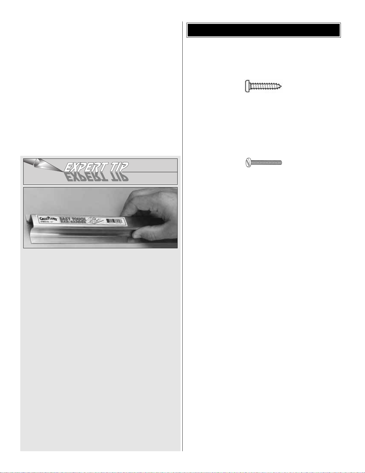
EASY-TOUCH™BAR SANDER
A flat, durable, easy to handle sanding tool is a necessity f or
building a well finished model. Great Planes makes a
complete range of Easy-Touch Bar Sanders and replaceable
Easy-Touch Adhesive-backed Sandpaper .While building the
Patriot XL, two 5-1/2" [140mm] Bar Sanders and two 11"
[280mm] Bar Sanders equipped with 80-grit and 150-grit
Adhesive-Backed Sandpaper were used.
Here’s the complete list of Easy-Touch Bar Sanders and
Adhesive Backed Sandpaper:
5-1/2" Bar Sander (GPMR6169)
11" Bar Sander (GPMR6170)
22" Bar Sander (GPMR6172)
33" Bar Sander (GPMR6174)
44" Bar Sander (GPMR6176)
11" Contour Multi-Sander (GPMR6190)
12' roll Adhesive-backed 80-grit sandpaper (GPMR6180)
150-grit (GPMR6183)
180-grit (GPMR6184)
220-grit (GPMR6185)
Assortment pack of 5-1/2" strips (GPMR6189)
We also use Top Flite 320-grit (TOPR8030, 4 sheets) and
400-grit (TOPR8032, 4 sheets) wet-or-dry sandpaper for
finish sanding.
• There are two types of screws used in this kit:
Sheet metal screws are designated by a number and a length.
For example #6 x 3/4"
This is a number six screw that is 3/4" long.
Machine screws are designated by a number, threads
per inch, and a length. SHCS is just an abbreviation for
“socket head cap screw”and that is a machine screw with a
socket head.
For example 4-40 x 3/4".
This is a number four screw that is 3/4" long
with forty threads per inch.
• When you see the term
test fit
in the instructions, it
means that you should first position the part on the
assembly without using any glue, then slightly modify or
custom fit the part as necessar y for the best fit.
• Whenever the term
glue
is written you should rely upon
your experience to decide what type of glue to use.When a
specific type of adhesive works best for that step, the
instructions will make a recommendation.
• Whenever just
epoxy
is specified you may use
either
30-minute (or 45-minute) epoxy or6-minute epoxy. When
30-minute epoxy is specified it is highly recommended that
you use only 30-minute (or 45-minute) epoxy, because you
will need the working time and/or the additional strength.
•
Photos
and
sketches
are placed before the step they
refer to. Frequently you can study photos in following steps
to get another view of the same parts.
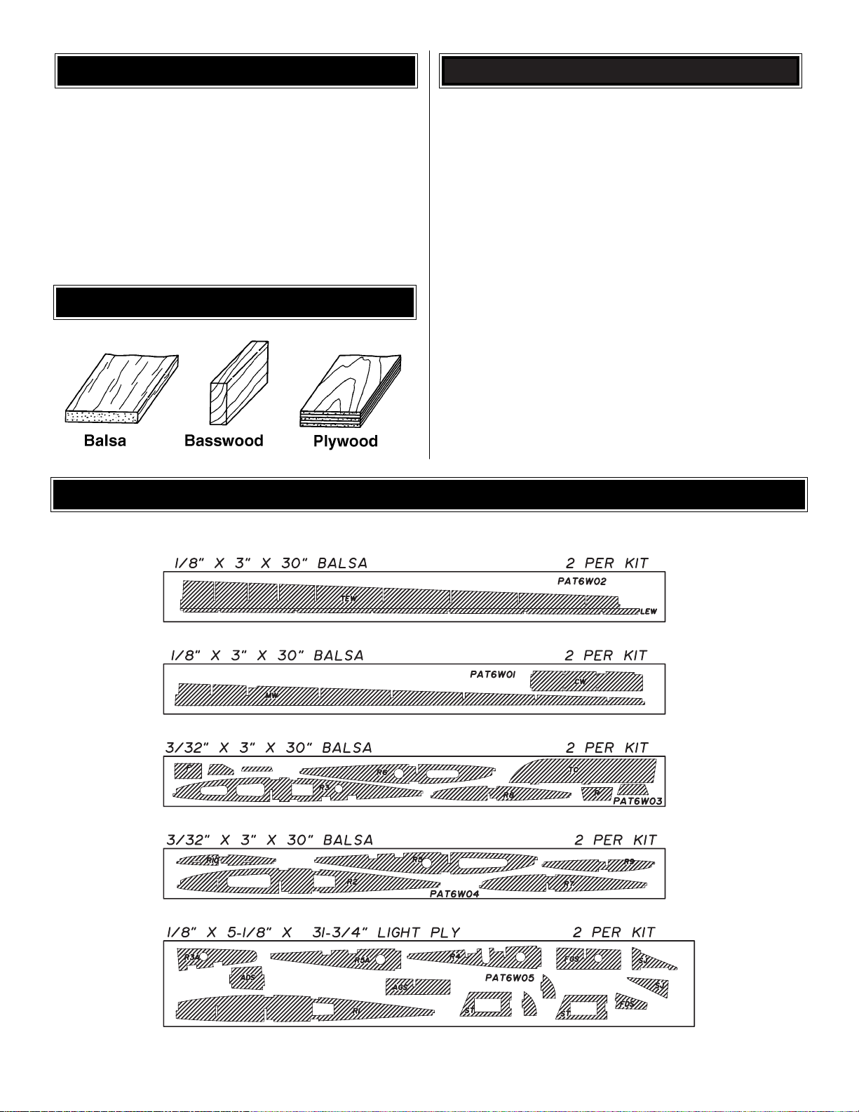
• Not all die-cut parts have a name, or their complete name
stamped on them, so refer to the die drawings f or identification.
When it’s time to remove the parts from their die sheets, if they
are difficult to remove, do not force them out. Instead, use a
sharp #11 blade to carefully cut the part from the sheet and
then lightly sand the edges to remove any slivers or
irregularities. Save some of the larger scraps of wood.
IMPORTANT BUILDING NOTES
5
Page 6
Fuse = Fuselage
Stab = Horizontal Stabilizer
Fin = Ver tical Fin
LE = Leading Edge
TE = Trailing Edge
LG = Landing Gear
Ply = Plywood
" = Inches
mm = Millimeters
SHCS = Socket Head Cap Screw
❏1. Unroll the plan sheets. Re-roll the plan inside out to
make them lie flat.
❏2.Remove all parts from the box.As you do, figure out the
name of each part by comparing it with the plan and the
parts list included with this kit. Using a felt-tip or ballpoint
pen, lightly write the part name or size on each piece to
avoid confusion later.Use the die-cut patterns to identify the
die-cut parts and mark them before removing them from the
sheet. Save all leftovers. If any of the die-cut parts are
difficult to punch out, do not force them! Instead, cut around
the parts with a hobby knife. After punching out the die-cut
parts, use your bar sander to lightly sand the edges to
remove any die-cutting irregularities or slivers.
❏3. As you identify and mark the parts, separate them into
groups, such as fuse (fuselage), wing, fin, stab (stabilizer)
and hardware.
GET READY TO BUILD
TYPES OF WOOD
COMMON ABBREVIATIONS
6
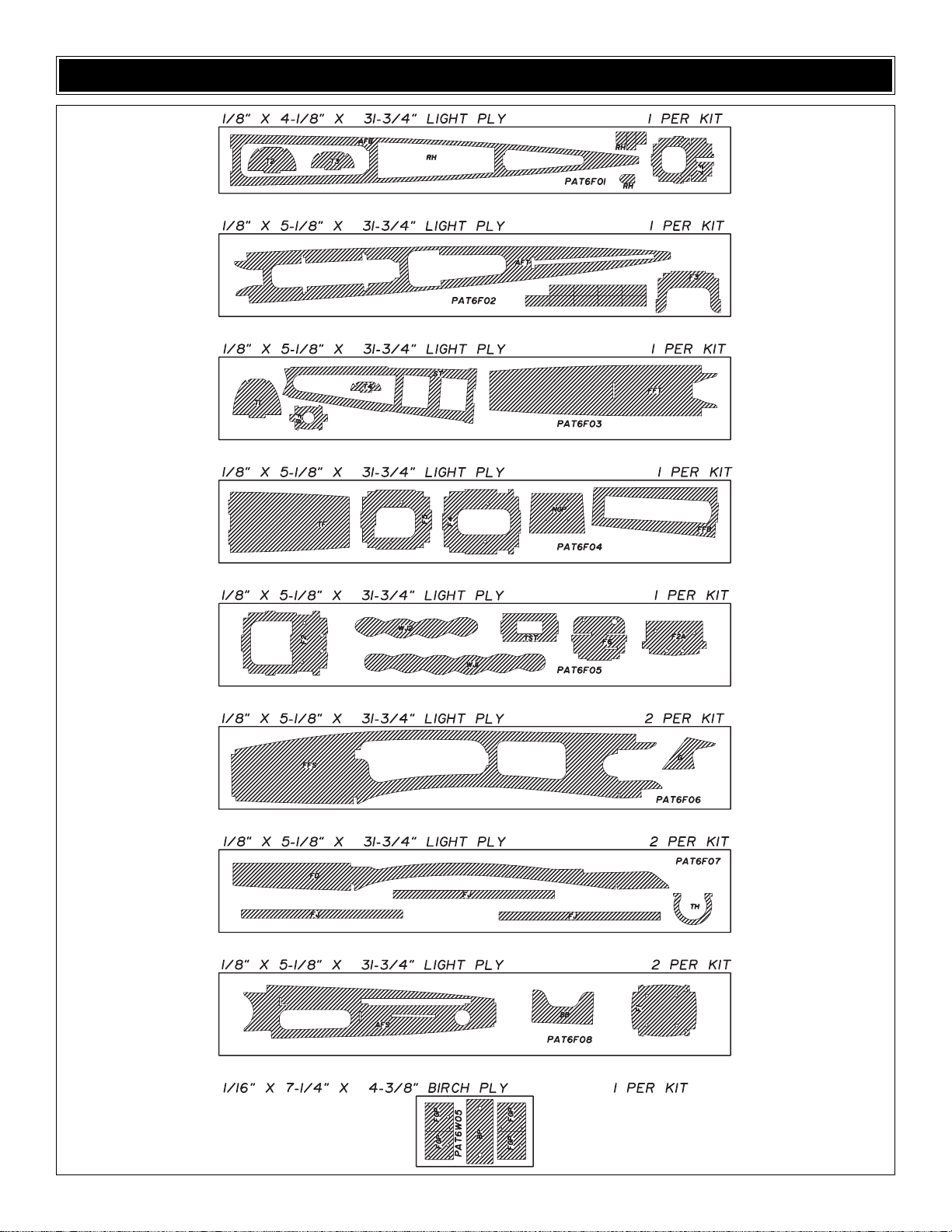
DIE-CUT DRAWINGS
Page 7
7
DIE-CUT DRAWINGS
Page 8
Note: While the placement of the outer framing of any stick-
built part is important, the exact placement of the internal ribs
is not so critical. It is more impor tant to have strong, secure
glue joints than to have the ribs placed in the exact location.
Note: We have removed the parts from the plan for clarity in
the some of the photos.
❏1. Position the fuse plan so the stab plan is over your flat
building board. Cover the plan with Great Planes Plan
Protector or wax paper so glue will not adhere.You may cut
the stabilizer drawing from the fuse plan along the dashed
lines if you wish.
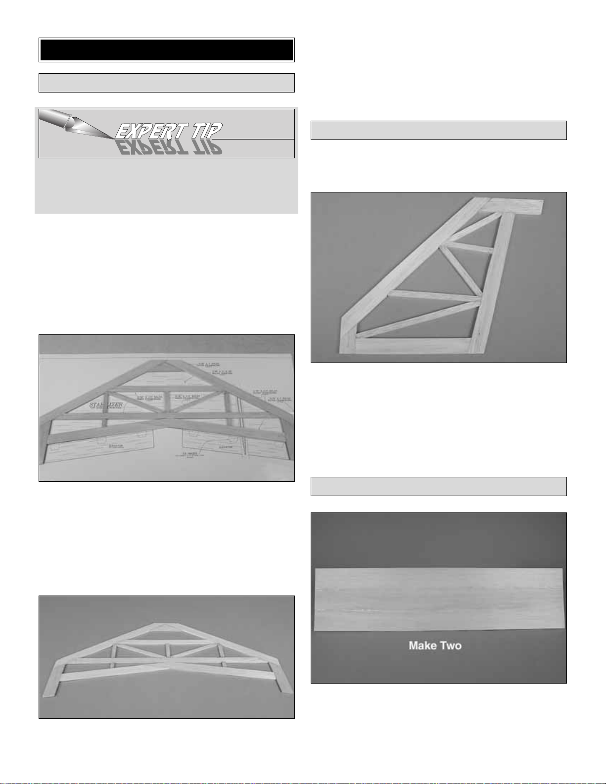
❏2. Build the stabilizer framework using the balsa sticks
indicated on the plan.Start with the 3/16" x 3/4" x 24" [4.8 x 19
x 610mm] outer framework, then the 3/16" x 1/2" x 24" [4.8 x
13 x 610mm] and 3/16" x 1/4" x 24" [4.8 x 6 x 609mm] inner
framework. Finish with 3/16" x 1" x 18" [4.8 x 25 x 460mm]
stab tips. As you proceed, use T-pins to hold the sticks to the
plan and use thin CA to glue the parts together. Note: Sa v e
any leftover sticks as they will be used for building the fin.
❏3. Remove the stab from the plan. Inspect all glue joints
and re-glue as necessary. Use a bar sander and 220-grit
sandpaper to sand both sides of the stab framework flat.Be
careful while sanding so that you do not over-thin any one
particular area of the stab or gouge the stab framework by
snagging sandpaper on it.
❏1. Place the fin plan on the building surface and cover
with wax paper or plan protector.
❏2. Using the leftover 3/16" [4.8mm] balsa sticks from the
stab assembly, build the fin in the same manner as the stab.
❏3. Remove the fin from the plan. Add thin CA to any joints
needing more glue. Sand flat using 220-grit sandpaper and
a bar sander.
❏ ❏1. Use the method described in the Expert Tip that
follows or your favorite method to glue together three
1/16" x 3" x 36" [1.6 x 95 x 760mm] balsa sheets to make
one 1/16" x 9" x 36" [1.6 x 230 x 760mm] stab/fin skin.Make
another skin the same way.
Sheet the Fin and Stabilizer
Build the Fin
Build the Stabilizer
BUILD THE T AIL SURF ACES
8
Page 9
HOW TO JOIN SHEETING
Note: Aliphatic resin can be used to join the sheeting, but
takes longer than CA to dry. If you choose to join using
aliphatic resin, be sure to allow the sheeting to sit a few
hours for the glue to dry. Aliphatic resin sands easier than
CA and is easier to cut.
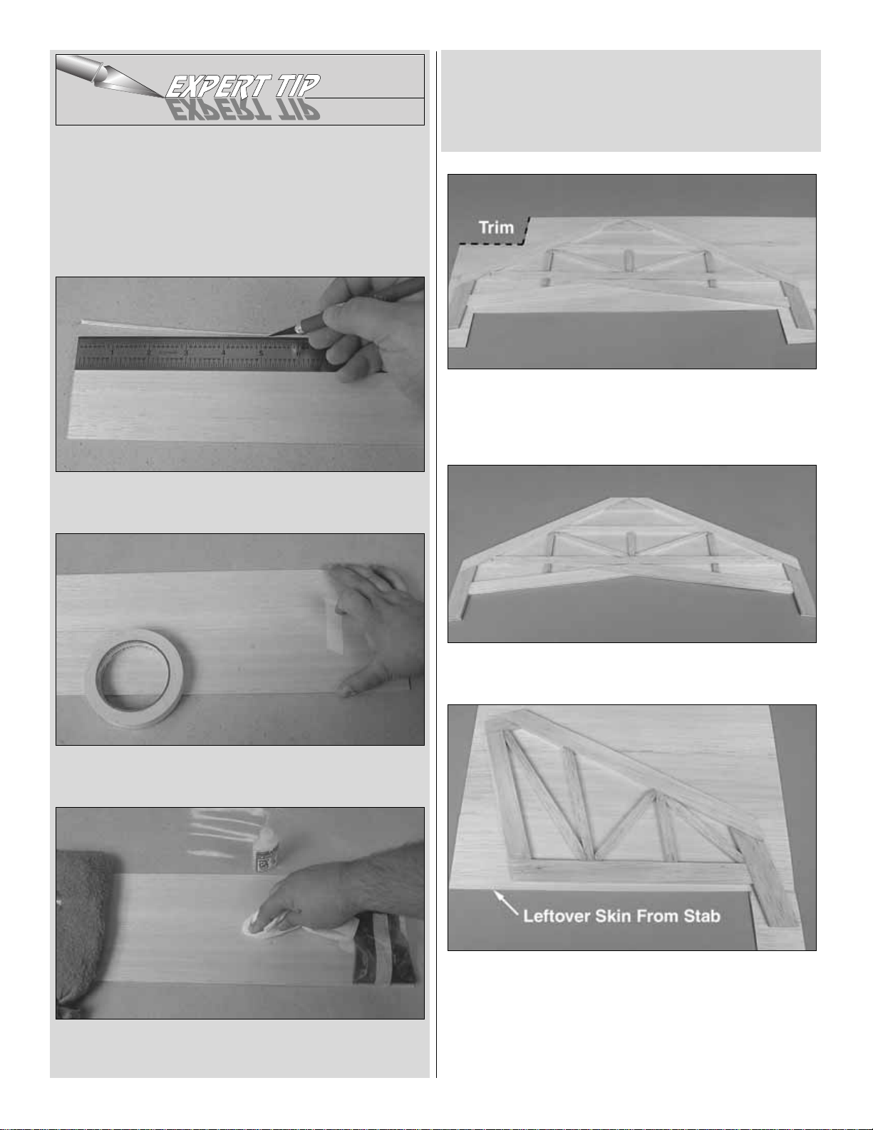
A. Use a straightedge as a guide to trim one edge of
both sheets.
B. Use masking tape to tightly tape the two sheets together
joining the trimmed edges.
C. T urn the sheet ov er and place weights on top of the sheet
to hold it. Apply thin CA sparingly to the seam, quickly
wiping away excess CA with a paper towel as you proceed.
D. Turn the sheet over and remove the masking tape.Apply
thin CA to the seam the same way you did for the other side
and use a fresh paper towel to wipe away excess CA.
E. Sand the sheeting flat and smooth with your bar sander
and 220-grit sandpaper.
❏ ❏2.Working over your flat building surface , use medium
CA to glue one side of the stab to one of the skins as shown
in the photo. Sheet the ends of the stab tips with a small
corner cut from the area shown.
❏ ❏3. Cut the excess sheeting from the stab. Save the
remainder for the fin.
❏ ❏4. Sheet the other side of the stab the same way.
Sheet both sides of the fin with the leftover sheeting.
Note: Give the CA ample time to harden before lifting the
assembly off the building board. It is essential to get a
secure and uniform bond between the stab sheets and the
stab framework, especially in the center.
9
Page 10
❏1.Cut the rudder to the length shown on the plan from the
shaped 25" [635mm] balsa rudder/elevator stick.(Note: The
elevators are also cut from this stick, so be careful with the
measurements.) Remember, measure twice, cut once!
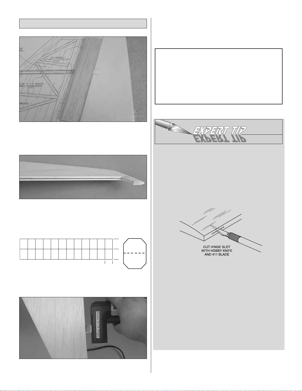
❏2. Use a Great Planes Precision Hinge Marking Tool or
measure and mark a centerline on the LE of the rudder and
the TE of the fin.
❏3. Mark the hinge locations where shown on the plan.
❏4. Cut nine 3/4" x 1" [20 x 25mm] hinges for the elevators
and rudder from the supplied 2" x 9" [51 x 230mm] CA hinge
strip, and then snip off the corners so they go in easier.
❏5. Using the centerlines as a guide, cut the hinge slots
where shown on the plan with a Great Planes Slot Machine,
then proceed to step 7. If you do not have a Slot Machine,
or cannot access one of the hinge locations with it, you will
need to follow the procedure for cutting hinge slots with a
hobby knife and #11 blades.
HOW TO CUT HINGE SLOTS WITH A HOBBY KNIFE
When using a hobby knife to cut hinge slots , one of the most
common mistakes made by modelers is making the slots too
tight. This restr icts the flow of CA to the back of the hinges.
Another mistake made when installing hinges is not using
enough glue to fully secure the hinge over its entire surface
area.This will result in hinges that are only
tack glued
.Follow
these steps to cut hinge slots with a hobby knife:
A. Using the centerline as a guide, cut one of the hinge slots
in the fin or rudder where shown on the plan with a #11
blade.Begin by cutting a shallow slit.Make three or four cuts
along the same line, going slightly deeper each time.As you
proceed, be certain to go straight into the wood and move
the knife from side-to-side until the blade has reached the
correct depth for the hinge.
B. T est fit a hinge into the slot.If the hinge does not slide into
the slot easily, remove the hinge and reinsert the knife,
working the blade back and forth a few times to provide
more clearance (it’s the back edge of the blade that does
the widening).
C. Cut the rest of the hinge slots the same way.
❏6.Tempor arily join the elev ators to the stab with the hinges,
adjusting any hinge slots if necessary so they all align.Do not
glue in the hinges until you are instructed to do so.
Notes about CA hinges: This kit is supplied with CA
hinge material consisting of a 3-layer lamination of Mylar
and polyester specifically made for hinging model
airplanes. When properly installed, this type of CA hinge
provides the best combination of strength, durability, and
easy installation. It is essential to install them correctly.
Follow the hinging instructions in this manual for the best
result. The techniques shown have been developed to
ensure thorough and secure gluing.
Build the Rudder and Elevators
10
1"
1"
3/4"
Page 11
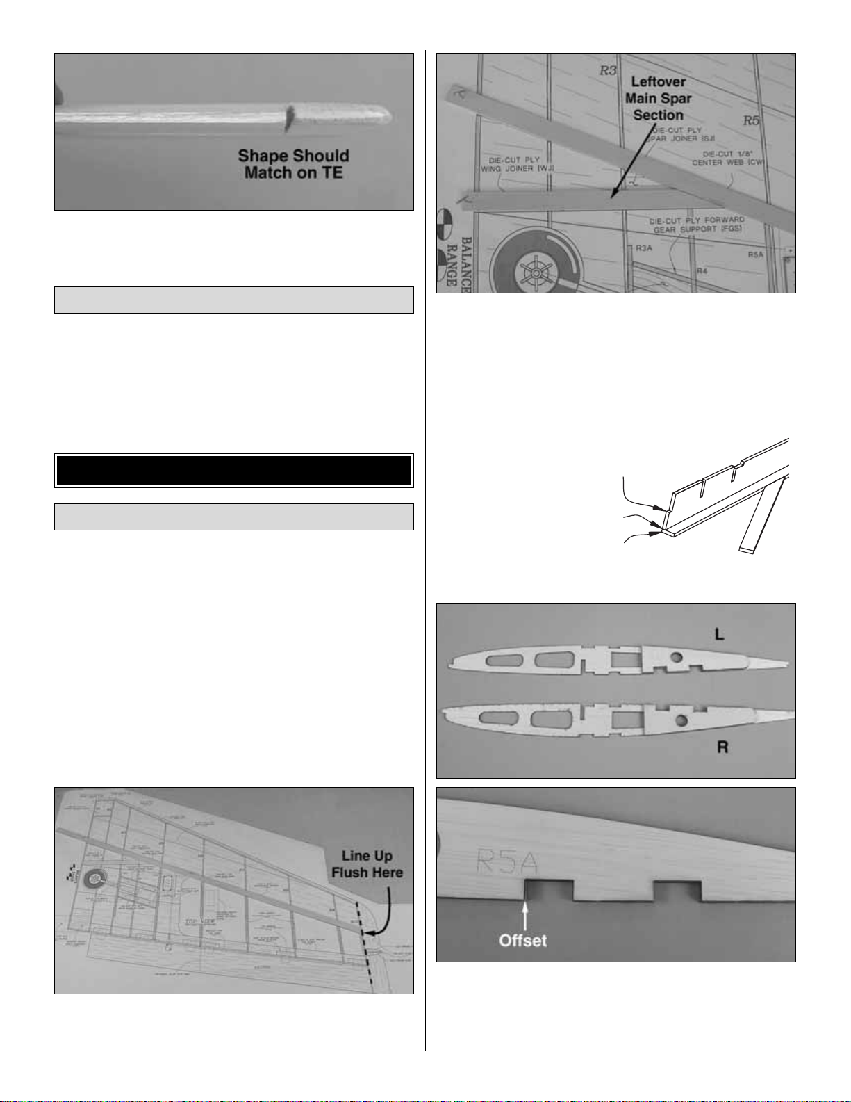
❏7. Sand the stab and fin tips to match the taper of the
elevators and rudder.
❏1. Shape the leading edge of the elevators and rudders to
a “V” as shown on the plans.
❏2. Use a bar sander and 150-grit sandpaper to round the
tail surfaces as shown on the plan.
Note: Wing construction is engineered to provide a straightand-true wing panel with minimum effort. To do so, the
building sequence and pieces are different from what you
may be accustomed to. Be sure to read all steps carefully
and pay particular attention to instructions of when and
where to apply adhesives.
Note: The wings are built upright over the plan. You may
build both wing panels at once following the instructions if
you have space to do so.
❏ ❏1. Lay the right wing panel plan on a flat building
board and cover with wax paper or plan protector.
❏ ❏2. Cut the bottom main wing spar to the length
shown on the plan from a 1/8" x 1/2" x 36" [3 x 13 x 910mm]
basswood stick.Pin the spar to the plan.
❏ ❏3. Cut the bottom aft wing spar from the leftover
1/8" x 1/2" [3 x 13mm] basswood stick.
❏ ❏4. Lay out the die-cut 3/32" [2.4mm] balsa wing ribs
R2 through R10 in the general area of their location on the
plan. Rib R4 will be installed in the last step and can be set
aside for now.
❏ ❏5. Place the die-
cut 1/8" [3mm] balsa
main wing web on
the spar along the
leading edge.
❏ ❏6. Use the 1/2" [13mm] holes to align the die-cut 1/8"
[3mm] plywood rib doublers R3A with ribs R3. Glue in place
with medium CA. Make a right and a left. Note: There is a
slight offset in the slots on the ribs as compared to the
doubler.This is normal.
Build the Wing Panels
BUILD THE WING
Finish the Tail Surfaces
11
Main Web
L.E.
Spar
Page 12
❏ ❏7. Use the 1/2" [13mm] holes to align the die-cut 1/8"
[3mm] plywood rib doublers R5A with ribs R5. Glue in place
with medium CA. There will be an offset built in just like in
the previous step.
❏ ❏8. Test fit ribs R2 through R10 on the main wing spar
and web.DO NOT install R4 until instructed to do so.
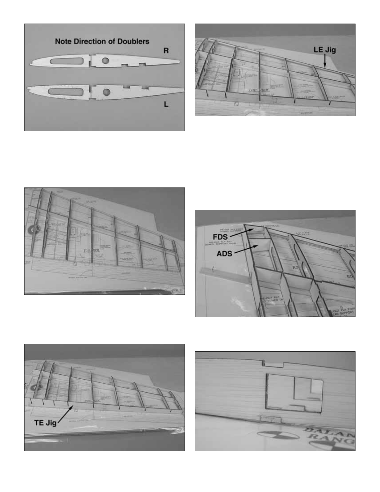
❏ ❏9.Test fit the die-cut 1/8" [3mm] balsa TE Jig. Insert the
wing ribs into the slots on the TE jig and align with the plan.
❏ ❏10.Test fit the die-cut 1/8" [3mm] balsa LE Jig. Insert the
wing ribs into the slots on the LE jig and align with the plan.
❏ ❏11.Once you've finished test fitting and are happy with
the fit, begin gluing using thin CA. Weigh down the TE to
keep it flat on the work bench. Starting at R2, glue the ribs
first to the TE and then to the LE.Ensure each rib is pressed
all the way down into the TE slots and the LE is pressed all
the way down onto each rib.After the LE jig and TE jig have
been glued, glue the center spar and center web into place
using thin CA.
❏ ❏12. Test fit R1, the die-cut 1/8" [3.2mm] plywood
forward dowel support (FDS) and the die-cut 1/8" [3.2mm]
plywood aft dowel support (ADS).
❏ ❏13. Make sure the bottom aft wing spar is pressed all
the way up into the slot in R1 and glue in place.
12
Page 13
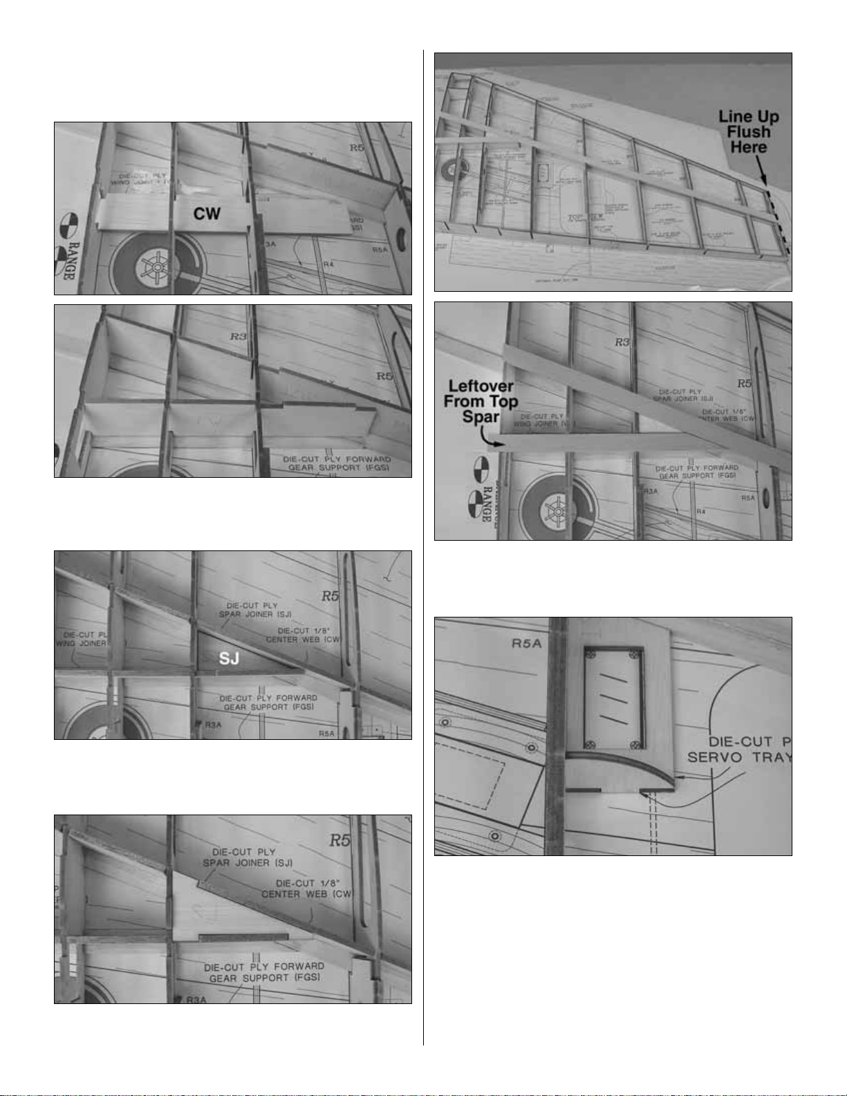
❏ ❏14. Use a straightedge to make sure R1 is straight
from the LE to the TE and glue in place with thin CA.
Note: R1 will have a few degrees of tilt.This is normal.
❏ ❏15. Inser t the die-cut 1/8" [3.2mm] balsa center web
(CW) into the slot in R1 until the notches line up with the
ribs.Twist into position.
❏ ❏16. Install the die-cut 1/8" [3.2mm] plywood spar joiner
(SJ) without tabs into the area marked on the plan. Glue in
place using thin CA.
❏ ❏17.Test fit the 1/8" [3.2mm] die-cut ply spar joiner (SJ)
with tabs. Glue in place with medium CA.
❏ ❏18.Test fit the top main wing spar and the top aft wing
spar.Glue in place with medium CA.
❏ ❏19. Locate the die-cut 1/8" [3mm] ply servo tray and
servo tray brace.Align the servo tra y with the plan and glue
in place using thin CA. Be sure the ser vo tray is even with
the rib on the bottom of the wing. Note: If building flaps
install the aileron servo tray the same way.
13
Page 14
❏ ❏ ❏ ❏1.Glue two 3/32" x 3" x 36" [2.4 x 75 x 910mm] balsa
sheets together to make one 3/32" x 6" x 36" [2.4 x 75 x 910mm]
LE sheet.
❏ ❏ ❏ ❏ 2.Align the edge of the LE sheeting with the center
of the top wing spar. Trim off the excess sheeting, leaving
about 1/4" [6mm] of over-hang on the wing LE and ends.
❏ ❏ ❏ ❏ 3. Soften the sheeting by rubbing warm water
into the side of the wood not being glued.This will allow the
balsa to conform to the shape of the wing when it is rolled.
❏ ❏ ❏ ❏ 4. Apply a thick bead of medium CA down the
center of the top wing spar and down each rib toward the
leading edge of the wing. Glue the sheeting to the LE.
❏ ❏ ❏ ❏ 5. Align the edge of the sheeting up with the
middle of the wing spar and, working quickly, roll the sheet
down towards the leading edge. A long sanding bar or
straight edge will help you apply even pressure.
❏ ❏ ❏ ❏ 6. Once the glue has set, trim the sheeting to
match the shape of the wing.
❏ ❏7. Flip the wing over and repeat steps 1-6 to sheet the
wing panel bottom from the main wing spar to the LE.
❏ ❏8.Locate two of the 3/32" x 3/4" x 30" [2.4 x 19 x 760mm]
balsa TE sheets. Test fit the TE sheeting and mark how far it
reaches up each rib so you know where to run the glue. Do
this for the top and bottom of the wing panel.
❏ ❏9. Apply a thick bead of medium CA on each rib and
the edge of the TE sheeting that rests against the TE Jig.
Glue the top and bottom TE sheeting in place.
❏ ❏10. Sheet the top of the wing center section with
3/32" x 3" x 36" [2.4 x 75 x 910mm] balsa sheets.The center
section sheeting rests flush against the TE sheeting and
should be trimmed just short of R6 to allow room to trim the
sheeting to match the plan. Glue with medium CA. The
second sheet should rest flush against the first sheet and is
glued in the same manner as the first. Do not sheet the
bottom center section until instructed to do so.
Sheet the Wing Panel Top
14
Page 15
❏ ❏11.Finally , fill in the last portion of center sheeting with
a leftover piece of 3/32" [2.4mm] sheeting.
❏ ❏12. Once the CA has fully hardened, trim the top center
section sheeting to match the inside curves shown on the plan.
Hint: For a guide to trimming the sheeting, we used a
Hobbico®Cloth Retractable Tape Measure to get the
curve angles for the inner cutout. It closely matches the
shape shown on the plan and will give you a nice rounded
corner that can easily be cut out. Lining up one edge of the
Hobbico tape measure with rib R6 will also give you a close
measurement to the actual plan cut out of the sheeting.
❏ ❏13. Locate the 3/32" x 1/4" x 30" [2.4 x 6 x 760mm]
balsa cap strips.The cap strips are cut to fit the rib between
the LE sheeting and the TE sheeting as shown, and are
centered on the rib.Pay special attention to the cap strip on
R10. It is not centered like the other cap strips, but is glued
to one side flush with the wing tip.
A single-edge razor blade works well for cutting the straight
lines needed to make the cap strips match the sheeting.
At this time you should start building the other wing
panel. Follow the above instructions to this point.
15
Page 16

❏ ❏1. Locate the 1/4" x 1/2" x 24" [6 x 13 x 610mm] maple
landing gear rail. Cut two landing gear rails to match the
plan. Set the leftover maple railing aside for use on the left
wing panel.
❏ ❏2. Locate the die-cut 3/32" [2.4mm] plywood FGS
(forward gear support) and AGS (aft gear support).
❏ ❏3. Slide R4 into position with AGS and FGS. The two
gear supports will help you align R4 according to the plan.
❏ ❏4.Test fit the two maple landing gear rails.
❏ ❏5.When everything is in place and you are happy with
the test fit, glue AGS, FGS, and R4 in place with medium
CA. Do not glue the maple landing gear rails at this time.
❏ ❏6. Once the CA has hardened, remove the two gear
rails. Mix a generous amount of 30 minute epoxy. Liberally
coat the side of the gear rail that touches the gear support
and to each slot the gear rail rests in.Press the gear rail into
place and wipe the excess epoxy away with a paper towel
and alcohol. Do this for both rails. Allow time for the epoxy
to cure before handling.
❏ ❏7. Locate the 3/8" x 3/8" x 30" [9.5 x 9.5 x 760mm]
balsa hinge block stick and cut it into six (6) 1-1/2" [38mm]
segments as shown on the plan.
❏ ❏8. Glue each hinge block in place according to the
plan.You may need to shape the blocks to fit snugly.
❏ ❏1. Glue the 3/8" x 5/8" x 30" [9.5 x 15.9 x 60mm] balsa
leading edge (LE) in place using medium CA.T rim the ends
to match the plan.
Begin Shaping the Wing
Install the Landing Gear Rails
16
Page 17

❏ ❏2. Glue the die-cut 3/32" [2.4mm] balsa wing tip
center (TC) into position. Be certain it is centered and
perpendicular to R10.
❏ ❏3. Locate the 3/8" x 3" x 24" [9.5 x 75 x 610mm] balsa
wing tip stick and the 1/2" x 3" x 24" [13 x 75 x 610mm]
balsa wing tip stick. Cut a piece from each stick to match
the plan for the wing tips.Note: The 1/2" [13mm] stick will be
on the top of the wing; the 3/8" [9.5mm] stick will be glued to
the bottom of the wing tip.Tr im to the approximate shape of
the wing tip and glue in place.Save all leftov er balsa from the
3/8" [9.5mm] stick.You will need it after joining the wing.
❏ ❏4. Shape the LE as shown on the plan.
Note: This section applies only to those modelers installing
pneumatic retracts.If you are installing fixed gear, proceed
to “
Install the Fixed Gear”
on page 18.
❏ ❏1. Test fit the retract between the landing gear rails.
You may have to trim R4 a little to allow the retract to seat
properly. The landing gear rails may also need a slight
sanding to allow the base of the retract to fit. Note how the
retract is inserted. This allows for the air fitting to be
accessed through the hole in R3.
❏ ❏2. Slide a 2-1/4" wheel onto an axle followed by a
5/32" [4mm] wheel collar. Apply a small drop of general
purpose oil to the axle. Tighten the set screw on the wheel
collar to hold the wheel in place. Using a file or rotary tool,
grind a flat spot onto the axle where the set screw touches.
This helps reduce the chance of the wheel collar slipping.
Install the Retracts
17
Page 18

❏ ❏3. Using a metal saw or rotary tool with cutting wheel,
trim the axle 1/8" [3mm] from the wheel collar.
❏ ❏4. Slide the wheel/axle assembly onto the strut.
❏ ❏5.Note the position of the wheel on the plan.Lower the
strut with the wheel/axle assembly in place. Slide the axle
on the strut until it is in the location shown on the plan.Grind
a flat spot onto the strut where the set screw touches.
Tighten the set screw on the axle to hold it in place.Trim off
the excess strut, leaving approximately 1/8".
❏ ❏6.Mark the location on R2 where the wheel touches.Trim
R2 to allow the wheel to fully retract inside the wing.It may also
be necessary to trim R3 to allow the strut to fully retract.
❏ ❏7. Once the retract is fitted, mark the holes for the
mounting screws. Drill 3/32" [2.4mm] holes for the retract
mounting screws, or as your retract manufacturer suggests.
❏ ❏1.Locate the 2-3/4" x 1" x 5/8" [70x25x16mm] basswood
fixed gear block and the die-cut 1/8" [3.2mm] plywood fixed
gear plate.Align the end of the plate with one end of the block.
Drill a 5/32" [4mm] hole through the block to fit the landing gear
wire using the hole in the fixed gear plate as a guide.
Install the Fixed Gear
18
Page 19

❏ ❏2. Insert the wire as shown. It may be necessary to
deepen the groove in the fixed gear block to allow the wire
to sit flush with the top of the gear block.
❏ ❏3. Mix a small amount of 30-minute epoxy. Epoxy the
fixed gear plate to the gear block and clamp together.Allow
the epoxy to fully cure.
❏ ❏4. Test fit the fixed gear block in the wing in the same
location as the retract mount, as shown on the plan. Drill
5/32" [4mm] holes for mounting the fixed gear .Some sanding
may be necessary to get a good fit between the rails.
Both wing panels should now be ready to be joined
following all previous steps.
❏1.Locate the two die-cut 1/8" [3mm] ply wing joiners, WJ1
and WJ2. Use 30-minute epoxy to glue the joiner together.
❏2. Test fit the wing panels with the wing joiner. Note the
direction of the “V-shape” of the wing joiner. The bottom of
the “V-shape” points to the bottom of the wing. Insert the
joiner by sliding it in at an angle and twisting into place.
Join the Wing Panels
19
Page 20

❏3. Mix 1/4oz of 30-minute epoxy.Liberally coat the root rib
of one wing half, half of the wing joiner, and center web with
epoxy. Insert the joiner and clamp in place against the
center web (CW). Be sure there is plenty of epoxy coating
the wing joiner and center web; it should ooze out of
everywhere when the clamp is compressed.
❏4. With one side of the joiner clamped in place, coat the
center web in the other wing half and the wing joiner.Twist
together the two wing halves.
❏5. Clamp the wing joiner in place. Make sure the wing is
straight and the wing roots meet with little or no gap.Clean up
excess epoxy with a paper towel and denatured alcohol.
When the epoxy has fully cured, remov e the clamps and fill in
any gaps with more epoxy.
❏6. Cut a 2" x 6" [50 x 150mm] block from leftover 3/8"
[9.5mm] balsa from the wing tip blocks. This is the center
LE. Glue it to the LE center of the wing and shape it to
match the wing.
❏7. Cut the shaped balsa bolt support to make two
supports.Trim each to match the plan and glue in place with
medium CA.
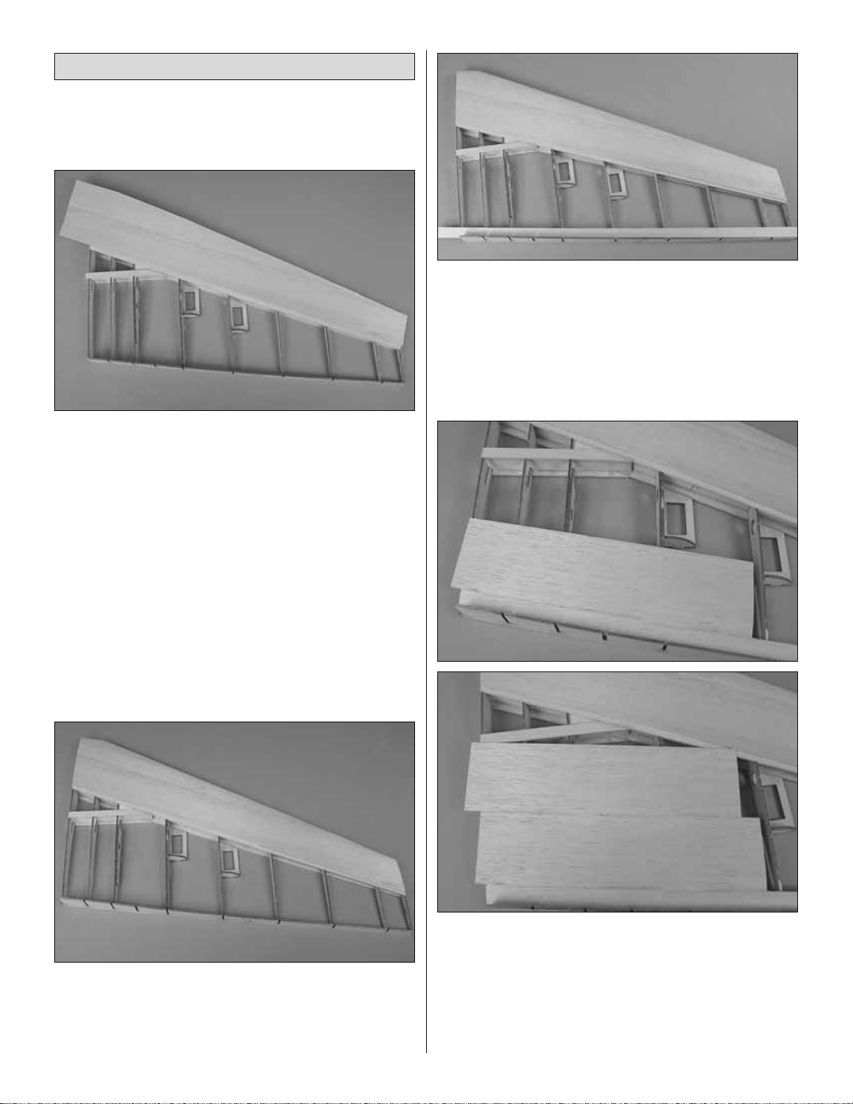
❏ ❏1. Sheet the bottom wing in the same manner as the
top, one half at a time.You will need to make a cutout for the
landing gear in the sheeting. The way we did this was to
install the first section of sheeting flush with the TE sheeting,
then position the gear.Trace the outline of the gear onto the
sheet.This way, you can align the plate with the outline when
the second sheet is glued and trace the remainder of the
cutout. Do not glue the sheeting to the areas to be cut out.
❏ ❏2. If you installed the flap servo tray, sheet it at this
time.Cut a piece of sheeting flush with the LE sheeting that
covers the tra y.Glue a cap strip from the bottom of the servo
tray to the TE sheeting as shown.
Sheet the Bottom of the Wing
20
Page 21

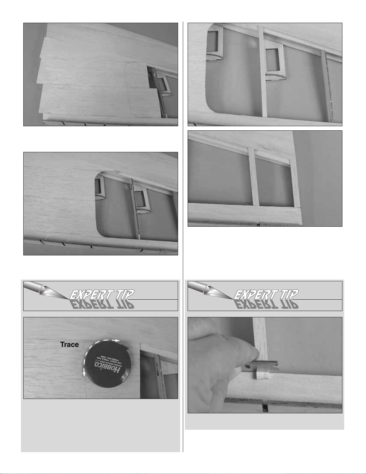
❏ ❏3. Cut out the sheeting over the servo trays. Slide a
servo into the tray and trace the outline of the servos’tabs.
Remove the servo and then trim the sheeting to allow the
servo to sit down into the cutouts.
❏ ❏4. If you installed retracts, trim the sheeting to
accommodate the retract.Install the retract and lower the strut.
Mark the sheeting where the strut and the wheel need to pass.
Remove the sheeting with a sharp hobby knif e.Cut 1/8" [4mm]
clearance around the wheel so it doesn’t contact the sheeting.
❏ ❏1.Locate the two shaped 25" [635mm] balsa ailerons.
Shape the LE for each side to match the plan.
If you are
installing flaps, you will need to cut the aileron at the location
shown on the plan.
Note: The flap hinges are slightly above
the centerline due to their shape. Refer to the plan.
❏ ❏2. Mark the centerline on the LE of the aileron and TE
of the wing as shown on the plan.Cut the hinge slots for the
ailerons and flaps if used.
❏ ❏3. Cut eight hinges from the supplied hinge material
and temporarily mount the ailerons (and flaps if installed) to
the wing.
❏ ❏4.With the control surfaces in place, sand the wing tips
to match the shape of the ailerons.
❏1. Using a bar sander and 200-gr it sandpaper, round all
edges and shape the wing to match the plans.
❏2. Carefully trim the TE jig even with the sheeting on the
bottom of the wing.
Note: We have removed the parts from the plan for clarity in
the some of the photos.
❏ ❏1. Clear your building surface; you will need a lot of
room for the fuse plan. Pin the side view to your building
board and cover with wax paper or plan protector.
Assemble the Fuse Formers and Sides
BUILD THE FUSELAGE
Finish Shaping the Wing
Install the Ailerons
21
Page 22

❏ ❏2. Locate the die-cut 1/8" [3mm] ply front fuse side
(FFS), the die-cut 1/8" [3mm] ply aft fuse side (AFS), and
two of the die-cut 1/8" [3mm] fuse joiners (FJ).
❏ ❏3. Lay the parts over the plan and pin them in position.
❏ ❏4. Glue the parts together, making sure there is a
straight line between AFS and FFS.
❏ ❏5. Locate the die-cut 1/8" [3mm] ply fuse doublers
(FD).Line up the doubler to the inside edge of the fuse side.
Glue in place using medium CA.
❏6.Repeat steps 1-5 to build the other side of the fuselage.
❏7. Next you will assemble the fuse top, so you will need to
position the plan so the bottom view is over the b uilding board.
Note: The fuselage is built upside-down over the plans.
❏8. Locate the die-cut 1/8" ply aft fuse top (AFT) and die-cut
1/8" ply forward fuse top (FFT) pieces and pin them in place
over the plan. The last two FJ pieces will join AFT and FFT
together like you did with the sides.Glue all the pieces together
using thin CA at the joints.Leave the fuse top pinned to the plan.
❏9. Locate the die-cut 1/8" [3mm] ply servo tray (ST),
former F6, and former F7. Test fit the pieces as shown.
Place the assembly over the fuse top in the position shown
on the plans and bring the fuse sides up meet F6 and F7.
There will be notches on the fuse sides to line it up. Make
sure the two formers are vertical and all the joints fit
together with minimal gaps.When satisfied with the fit, glue
in place with medium CA.
❏10. Locate die-cut 1/8" ply former F5 and the die-cut 1/8"
ply throttle servo tray (TST). Fit these pieces as shown
and glue together.Ensure F5 remains vertical.
❏11.T est fit, then glue in place, die-cut 1/8" plywood f ormer F4.
❏12. Now that you have formers F4 through F7 in place
and both servo trays installed, you can glue the die-cut 1/8"
ply fuse bottom in position.
22
Page 23

❏13. Test fit former F8. Notice the sides of the fuse will
need to bend slightly to conform to F8. Wet the ends of the
fuse sides and wrap F8 with rubber bands as shown. The
water will allow the fuse sides to conform to F8.
❏14.Locate four (4) of the 1/2" x 1/2" x 30" [ 13 x 13 x 762mm]
balsa fuse corners. The span between F4 and F7 is flat.
Weight down the fuselage at F4 and F7.Working on the bottom
of the fuselage first, glue both fuse corners to F4 first, then glue
both corners to F7.This helps eliminate any tendancies to twist
the fuselage.
❏15.Glue the sides of the fuse to the fuse corners between
F4 and F7.
❏16. Once the sides and bottom corners are securely
glued in place between F4 and F7, you can then glue the
corners to F8. Lay a bead of medium CA where the corner
will sit in F8, then wrap your hand around the tail and both
corners and squeeze the corners into place. Allow the glue
to harden while holding it in place. Go back after gluing the
corners into F8 and glue the sides in place using thin CA.
❏17. Glue F2A to the front of F2 with medium CA. Align the
pieces using the factory-cut holes.This assembly is now F2.
❏18. Glue formers F2 and F3 in place using thin CA.
❏1. Use 30-minute epoxy to glue together the two die-cut
1/8" plywood formers F1.From now on, this assembly will be
referred to as the firewall. Install four 6-32 blind nuts in F1.
Apply a small amount of epoxy or CA to the back of the b lind
nuts to hold them in place.
Install the Firewall
23
Page 24

❏2. If using fixed gear, skip to step 4. If installing retracts,
you will need to glue the die-cut 1/8" [3mm] plywood nose
gear plate (NGP) to the 1/8" [3mm] tank floor (TF).Drill four
5/32" [4mm] holes through the punchmarks in the NGP.
❏3. Drill four 5/32" [4mm] holes and install 6-32 blind nuts
on the back of the tank floor.The back is the side you glued
the NGP to.
❏4. Test fit the tank floor. Use a clamp or rubber bands to
hold the fuse sides together, pinching the floor in place.
Glue the floor in place.
❏5.T est fit, then glue the firewall into position using 30-min ute
epoxy. Use rubber bands or clamps to hold the fuse sides tight
to the firewall.The same way you did with former #8. Do not
disturb the fuselage until the epoxy has fully cured.
❏6. Flip the fuselage over and use weights to hold it down
at F2 and F4.
❏7. Locate four of the 1/2" x 1/2" x 30" [13 x 13 x 762mm]
balsa fuse corners. Star t at F4 and glue a section from F4
to F1. Do both sides simultaneously.Then glue from F4 to
F8. Again, do both simultaneously.
❏8. Glue the two die-cut 1/8" [3mm] ply bolt blocks (BB)
together using medium CA.
❏9. Test fit, then use epoxy to glue the bolt block in place.
24
Page 25

Before finishing the bottom of the fuselage,
we’ll mount the wing.
❏1. Fit the wing into the fuselage. Taking accurate
measurements, center the wing from side-to-side. Holding
the wing in position, use the holes in F2 as a guide to drill
1/4" [6.4mm] holes through the leading edge of the wing.
❏2. Remove the wing. Use the holes in the wing as a guide
to drill the holes the rest of the way through the webbing
inside the wing.
❏3.Round one end of both 1/4" x 3-1/2" [6.4 x 89mm] wing
dowels. Use 30-minute epoxy to glue both dowels into the
wing with 3/8" [10mm] protruding.
❏4. After the wing dowel epoxy has cured, fit the wing to
the fuselage. Measure the distance from the end of the
fuselage to both wing tips.Pivot the wing until the distances
are equal as show by B=B in the sketch.
❏5. Glue the die-cut 1/8" [3mm] plywood wing bolt plate
to the bottom of the wing as shown. Double check the
measurements taken in the previous step to be certain the
wing is centered.
❏6. Using the holes in the wing bolt plate as a guide, drill
#7 holes through the wing and the bolt block in the fuselage.
Remove the wing.
❏7.Use a 1/4-20 tap to cut threads into the holes in the bolt
block. Add several drops of thin CA to the threads, allow to
fully harden, and then retap the threads.
❏8. Enlarge the holes in the wing only with a 1/4" [6.4mm]
drill.T est fit the wing to the fuselage with two 1/4-20 x 2" [50mm]
nylon wing bolts. Make adjustments where necessary.
Mount the Wing
25
B=B
B
B
Page 26

❏1. Glue the die-cut 1/8" [3mm] ply forward fuse bottom
(FFB) in place using medium CA.
❏2. Glue the leftover 1/2" [13mm] corner pieces in place.
❏3. Sand the corners of the fuse to match the shape of the
die-cut 1/8" plywood gauge.
Start with a bar sander and 80-grit sandpaper to get the
approximate shape of the corners, then use a finer grain
sandpaper to better shape it.Adhesive-backed, 220-grit paper
attached to a piece of foam makes an excellent fine sander.
❏4. If you are installing retracts, now is a good time to fit the
retractable nose gear.Install the retract into the nose of the
fuse.You may hav e to trim FFB a little to allow the base of the
retract to clear.Test fit the axle, wheel collar and 2" [57mm]
nose wheel on the strut. Note where the wheel and the axle
Finish the Bottom of the Fuselage
26
Page 27

need to be positioned to clear the wheel well. Mark the axle
and strut and cut off 1/8" [3mm] after the mark. Make flat
spots on the axle and strut where the set screws tighten.
❏5. Locate two plastic 3/16" x 36" [5 x 914mm] pushrod
tubes. Sand the tubes with coarse sandpaper to allow the
CA to adhere.
❏6. Guide the pushrods through the firewall and the tail as
shown on the plan.The throttle pushrod tube will stop at F5, just
before the throttle servo.The nosewheel steering pushrod tube
will stop at F6.Cut off the excess tubes.If installing retracts, the
nosewheel steering pushrod will begin between F1 and F2.
❏7. Glue each section that passes through a former with
medium CA.
❏8.Insert the leftover tubes through the slots in the rear of the
fuse and into the hole in F7. The tube should extend past F7
by approximately 1/8" [3mm].Glue the tubes in place at F7.
❏9. Mix a batch of 30-minute epoxy with microballoons or
talcum powder to create a thick, strong, easy-to-sand filler.
Epoxy the tubes into the slots. Completely fill the slots with
the mixture.
❏10. After the epoxy has cured, use a bar sander and 150-
grit sandpaper to sand the outer pushrod tubes and epoxy
filler flush with the fuselage sides.
❏11. Locate the nine die-cut 1/8" [3mm] plywood braces.
Glue these in place with medium CA wherever there is a
joint on the fuse frame. Shown in the photo are the joints
where the fuselage joiners join FFS and AFS. Brace similar
joints throughout the model.
❏1. Locate the four die-cut 1/8" [3mm] plywood turtle deck
formers (T1-T4).
❏2. Use the gauge you used to shape the corners of the
fuselage to fit T1 as shown and glue in place using thin CA.
Build the Turtle Deck
27
Page 28

❏3. Glue T2 through T4 in place using thin CA. Check to
make sure they are perpendicular to the fuse by using a
square, or Hobbico Builders Triangle.
❏ ❏ 4. Locate the two 1/8" x 1/4" x 30" [3 x 6 x 760mm]
balsa turtle deck stringers.You will notice there are slots
in the formers for these stringers. Using medium CA, glue
the stringers in place from T1-T4. Trim and sand the ends
flush with formers T1 and T4.
❏ ❏ 5. Position a 3/32" x 3" x 30" balsa sheet as shown.
Trim the sheeting approximately 1/8" [3mm] past the TD
stringers. Be careful not to trim too much. When the
sheeting rolls over, it should clear the TD stringers.
❏ ❏ 6. Run a bead of medium CA on the bottom edge of
the sheeting and glue to the fuse top. When the glue has
hardened, wet the balsa sheeting with warm water. Allow
the water to soak in.This will allow you to bend the sheeting
like you did on the wing. CA activator may help you here.
Spray the sheeting with activator prior to running the bead
of glue on the stringers and formers. So when you roll the
sheeting over, the activator cures the CA instantly.
Otherwise, apply CA the TD formers and the TD stringers
with medium CA and roll the sheeting over. Hold in place
until the CA hardens. Repeat for the other side of the TD.
❏7. Once you have both sides sheeted, trim the sheeting to
match the TD f ormers.Use a sanding bar and 150-grit paper
to make the sheeting flush along the top.
❏8.Locate the 1/4" x 2" x 30" balsa [6 x 50 x 760mm] turtle
deck top.Test fit the TD top; it should rest flush on all sides
and be level.Sand as needed for a good fit.
❏9.Apply a bead of CA along the top of the TD formers and
stringers and firmly press the TD top down to glue in place.
28
Page 29

❏10. Measure and mark a centerline down the TD top.This
will act as your guide during the shaping.
❏11. Sand the turtle deck to the shape shown on the cross-
section. Sand the leading edge flush with T1 and the trailing
edge flush with T4. Note: Fill any gaps with Hobbylite
™
Balsa colored filler.
❏1. Locate the die-cut 1/8" [3mm] plywood radio hatch
(RH) and die-cut 1/8" [3mm] plywood radio hatch supports.
Glue the two hatch supports to the inside forward of the
hatch area and the curved support to the aft section as
shown on the plan.
❏2. Glue the die-cut 1/8" x 1" [3 x 25mm] plywood support
to the radio hatch.
❏3. Drill a 1/16" pilot hole as shown on the plan. Remove the
hatch and enlarge the hole to 3/32" [2.4mm].Use a #2 x 3/8"
[9.5mm] screw and #2 flat washer to secure the hatch.
Install the Radio Hatch
29
Page 30

❏1. If you have not already done so, mak e sure the stab and
fin are final-sanded smooth. Mount the wing to the fuselage.
❏2. Insert the stab into the slot in the sides of the fuse.
Measure the distance from a center point forward and the
outside corner of the TE of the stab. Also measure the
distance from the outside corner of the TE to the fuse side.
These measurements should be equal as well.
❏3.Stand about six to ten feet [2 to 3 meters] behind the model
and see if the stab is parallel with the wing.It may be necessary
to shim the stab to get proper alignment with the wing.
❏4. Once the stab is aligned, use a fine tip ballpoint pen
to mark the stab where it enters the fuselage on the top
and bottom.
❏5. Remove the stab and mix up a generous amount of 30
minute epoxy. Brush epoxy inside the area you just marked
and slide the stab back into place.Use the lines you drew as
a reference. Clean up excess epoxy with a towel and
denatured alcohol. Verify alignment and allow the epoxy to
fully cure before proceeding.
❏1. Cut the threaded end of the rudder torque rod to the
length shown on the plan.
❏2. Screw the 4-40 nylon torque rod horn on the threaded
end of the torque rod to the location shown.
Mount the Fin to the Fuse
B
Mount the Stabilizer to the Fuse
30
C
L
A=A B=
BB
AA
Page 31

❏3. Mark the TE of the fin where the nylon bearing on the
torque rod will be inserted. Mar k the rudder where the arm
of the torque rod will be inserted. See plan for locations.
❏4.Drill a 7/64" [3mm] hole 5/8" [16mm] deep in the leading
edge of the rudder at the mark you made for the rudder
torque rod.Cut a groove in the rudder for the rod .The Great
Planes Groove Tube™works great for this task. Test fit the
rudder torque rod in the rudder.Cut a slot in the trailing edge
of the fin at the marks you made for the nylon torque rod
bearing. Without using any glue, test fit the rudder to the fin
with the rudder torque rod in place. When satisfied with the
fit, remove the rudder and set it aside.
❏5. Glue the bearing in place with epoxy, being careful not
to get any glue on the rod or in the bearing. DO NOT GLUE
THE RUDDER IN PLACE AT THIS TIME.
❏6. Slide the fin fully into the fin slot. Usa a fine tip ballpoint
pen to mark the fin where it enters the slot on both sides.
Remove the fin.Mix a generous amount of 30 minute epoxy .
Apply epoxy to the top of the stab through the fin slot and to
the sides of the fin below the lines. Insert the fin, being
careful not to get epoxy on the nylon torque rod bearing.
❏7. Use a builders triangle to make sure the fin is vertical
and hold it in place with masking tape while the epoxy cures.
Wipe away excess epoxy with denatured alcohol and a
paper towel.
❏1. Assemble and install the tank cap.Attach a 12" [300mm]
piece of fuel tubing to the upper nipple, which will attach to the
muffler pressure tap. Attach a second piece of 12" [300mm]
fuel tubing to the main nipple in the center of the tank cap,
which will attach to the carburetor.
Install the Fuel Tank
31
Page 32

❏2. Remove the tank and fuelproof the fuel tank
compartment with thinned out epoxy or fuelproof doping.
❏3. Drill two 1/4" [6mm] holes in the firewall above the tank
floor as shown. Route the two 12" [300mm] lengths of fuel
tubing from the tank through these holes and into the tank
compartment. Pull the fuel tank into place with the fuel tubing.
Note: Some modelers may wish to wrap the tank in foam
prior to installing it.This is fine, but it will be a tight fit. Simply
bracing it with small balsa blocks after sliding it in will be
perfectly acceptable.
❏1. Cut the “spreader bars” from the included Great Planes
engine mount, and then use a hobby knife to remove any
flashing leftover from the molding process so that the halves
fit together well.
❏2.Temporarily attach the engine mount to the firewall with
four 6-32 x 1" socket head bolts and #6 flat washers but do
not tighten the screws all the way.
❏3. Place the engine on the mount and slide the halves in
or out until the engine fits. When the engine mount is
adjusted and positioned, tighten the mounting screws.
❏4.Position the engine on the mount so the drive washer (or
the back of the spinner) is 5-3/8" [137mm] from the firewall.
❏5. Use the Great Planes Dead Center
™
Engine Mount
Hole Locator or another method to mark the locations of the
bolt holes. Remove the engine from the mount and drill four
#36 or 7/64" [2.8mm] holes.Tap the holes with a 6-32 tap.
❏6. Bolt the engine to the mount with four 6-32 x 3/4"
[19mm] socket head screws , #6 w ashers, and loc k w ashers .
❏7. If installing retracts, proceed to “
Install the Servos
and Pushrods
.”
❏8. Mount the nose gear to the engine mount as shown
using a nylon steering arm with a 5/32" wheel collar and a
6-32 x 1/2" [13mm] socket head cap screw, another 5-32"
wheel collar and a 6-32 set screw .Position the wheel collars
so the gear will be positioned as shown (with the coil in the
wire approximately 1/8" [3mm] from the bottom of the
fuselage.) Be sure to grind flat spots on the nose gear wire
where the steering arm set screw and wheel collar set
screw will tighten.
Mount the Engine
32
Page 33

❏1.Mount the throttle servo as shown on the plan using the
hardware that came with your servo. Once the servo is
mounted, remove the screws and servo.Add a few drops of
CA to each hole to harden the threads.Allow the CA to fully
harden, and then reinstall the servo.
❏2. Install a screw-lock connector on the throttle servo
arm on the furthest-out hole.
❏3. Install a nylon clevis and retainer to the 42" [1070mm]
throttle pushrod wire.Slide the pushrod through the pushrod
tube with the clevis on the carb end.
❏4. Bend the carb end of the throttle pushrod as needed to
fit the engine installation. Make adjustments to the bends in
the wire so the pushrod aligns with the carburetor arm on
the engine, and then temporarily connect the pushrod to the
carb arm.Temporarily mount the muffler and make sure the
throttle pushrod will not interfere with the muffler. Make
adjustments to the bends in the wire if necessary.
❏5. Slide the pushrod wire through the screw-lock connector
on the throttle servo and temporarily tighten the screw.
❏6.Insert the two elev ator servos, the rudder servo , and the
retract servo (if used) as shown. Align the servos with the
pushrods and mount the servos using the screws provided
by the servo manufacturer. Once the servo is mounted,
remove the servo and harden the threads with thin CA.
❏7. If installing fixed gear, route the remaining 42"
[1070mm] pushrod through the firewall and guide tube until
it reaches the servo. Install a screw lock connector on the
rudder servo arm for the nose wheel. If you installed
retracts, see the photo above for reference. With a nose
gear retract, the pushrod and pushrod tube will not exit the
firewall. You will need to cut the pushrod and tube to the
approximate length shown.Using a leftover balsa stick, make
a support for the pushrod tube inside the tank area. Attach
the clevis to the steering arm on the retract.
Install the Servos and Pushrods
33
Page 34

❏8. Thread a nylon swivel clevis and retainer onto the 12"
[300mm] pushrod (threaded on one end).Connect the clevis
to the rudder torque rod and mark the point where the
pushrod crosses the rudder servo arm. Make a 90° bend at
that point in the pushrod. Inser t the pushrod into the servo
arm. Snap in place using the nylon Faslink as shown. Tr im
off all but about 1/16" [1.6mm] past the Faslink.
❏9. Thread a nylon clevis and retainer onto the 12"
[300mm] pushrod (threaded on one end) for the elevator
pushrod. Slide the pushrod wires through the two elevator
pushrod guide tubes, which are on the left and right sides of
the fuselage. Remove the backing plate from a nylon
control horn and connect the horn to the clevis in the outer
hole. Fit the elevator to the stab, using the hinges to hold
them in place. DO NOT GLUE THE HINGES IN PLACE.
❏10. Position the control horns on the elevators as shown in
the sketch and on the plan. Use a ballpoint pen to mark the
location of the control horn mounting holes and drill 3/32"
[2.4mm] holes at the marks. Temporarily mount the control
horn to the elevators with the backing plate and 2-56 x 5/8"
[16mm] screws.
❏11. Attach the elevator pushrods to the servos with Faslinks
using the same procedure as you did with the rudder.
❏12.Install the wing servos using the screws and hardware
provided by your manufacturer.
❏13. Thread a nylon clevis and retainer onto each of the
four 6" [150mm] pushrods.
❏14. Position the control horns on the ailerons and flaps as
shown on the plan.Use a ballpoint pen to mark the location of
the control horn mounting holes and drill 3/32" [2.4mm] holes
at the marks. Temporarily mount the control horn to the
ailerons with the backing plate and 2-56 x 5/8" [16mm] screws.
❏15. Connect the clevis to the control horn. Center the
ailerona and position the servo arms perpendicular to the
servo case. Hint: A small clamp can help hold the ailerons
even with the wing tip as shown.
❏16. Align the pushrod with the outer hole on the aileron servo
arm. Mar k the pushrod where it crosses the servo arm. Bend
the pushrod down 90° at the mark.Enlarge the hole in the servo
arm slightly with a 5/64" [2mm] drill bit and insert the pushrod.
❏17. Install the Faslink first, then trim to 1/16" past the
bottom of the Faslink.Do this for both aileron servos.
❏18. The flap linkages are done the same as the ailerons
with one difference. The servo arm on the flaps will be
angled toward the flap as shown.This will give you the angle
needed to deflect the flaps to their full extent.
34
Page 35

❏Assemble the instrument panel as shown.
❏1. Locate the two halves of the cowl and carefully cut
out the two halves.Cut as close to the bottom of the molding
as possible.
❏2. Test fit the cowl halves. Trim as necessary to get the
two halves to meet flush.
❏3. Using masking tape, hold the two halves of the cowl
together as they would be when attached to the fuse.
❏4. Cut two strips of leftover ABS plastic to make braces for
the inside of the cowl where they are joined. Be sure to leave
enough room for the cowl to slide ov er the fuse, so the sheeting
does not get in the way. Glue in place using medium CA.
Assemble the Cowl
Assemble the Instrument Panel
(Optional)
35
Page 36

❏5. Now that the cowl halves are joined, sand each joint
lightly so any filler used will adhere. We recommend filler
such as Bondo or Squadron White Putty. We used
Squadron Green Putty for clarity in photos.When the filler
has dried completely, wet sand with 400-grit sandpaper to
get the cowl ready for priming.
❏6. Make a cutout in the cowl to allow the engine to clear
the cowl. An easy way of doing this is: While the engine is
mounted, take a large piece of leftover balsa (or
heavyweight paper), and tape it to the side of the fuselage.
Mark the location where the engine contacts the balsa and
cutout the shape.Then remove the engine, leaving the balsa
taped to the fuse. Slide the cowl into place and trace the
outline of the engine onto the cowl. Cut away the area
marked by your template.
❏7. Remount the engine and test fit the cowl. Make any
adjustments necessary to clear the engine.
❏8. Attach the spinner backplate to the engine crankshaft.
The spinner backplate should be approximately 1/8" [3mm]
in front of the cowl.Once the cowl is in place, attach it to the
fuselage using #2 x 3/8" screws and #2 washers.
❏9. Prime and paint the cowl to match the model.
❏1. Cut the ABS tail fairing just outside of the cut lines.
The lines are there as a “guide” for a proper fit. You may
need to trim more or less depending on how you shaped the
turtle deck. Test fit and trim as needed. It should look close
to the photo above.
❏2. Cut the side air intakes along the cut lines.Test fit and
trim as needed to resemble photo.
❏3. Cut the tail cone approximately 1/4" [6mm] longer than
the cut line.This gives you some play in getting the cone to
fit.Test fit and trim as needed for a good fit.
Install the ABS Plastic Details
36
Page 37

❏1.Reinstall the fuel tank, running the carb and vent lines out
of the holes in the firewall.Mark on the firewall with permanent
marker which line is vent and which line is carb (fuel).
❏2. Connect the fuel lines to the carb and exhaust.
❏3. Mount the landing gear to the fuselage.
❏4. If you used pneumatic retracts, run all air tubing and
install the gear.
❏5. Install the air cylinder for your retracts as shown using
the 1/8" [3mm] air tank holders.Push the ends of the air tank
holders in the slots and slide forward into place.
Do not confuse this procedure with “checking the C.G.”, which
will be discussed later in the manual. A model which is not
laterally balanced may exhibit a variety of unpleasant traits,
ranging from uncharacteristic tip stalls to problems with spin
entries.This aircraft, when balanced properly, exhibits none of
these tendencies. Be sure to check the lateral balance
carefully as described to help ensure that the model exhibits
the same exceptional handling qualities as our prototypes.
❏1. With the wing level, have an assistant help you lift the
model by the engine propeller shaft and the bottom of the
fuse under the TE of the fin.Do this several times.
❏2. If one wing always drops when you lift the model, it
means that side is heavy. Balance the airplane by adding
weight to the other wing tip.An airplane that has been laterally
balanced will track better in loops and other maneuvers.
❏1. Remove all the pushrods and control horns from the
ailerons, elevators, and rudder.Remove the engine, engine
mount and any other hardware you may have installed
❏2. Most of the model should be rough-sanded by now, with
all the tabs and rough edges sanded even.Fill all dents, seams,
low spots, and notches with HobbyLite™Balsa Colored Filler.
❏3. After the filler has dried, use progressively finer grades
of sandpaper to even all the edges and seams and smooth
all surfaces. Remove all balsa dust from the model with
compressed air, a vacuum with a brush, or a tack cloth.
❏4. If you used retracts, install the air hoses and mount the
air cylinder as shown.
❏1. Install all ser vos using the hardware supplied by your
radio manufacturer.
❏2. Cut two 3/4" [19mm] holes in the wing to route the
servo leads. If you look inside the wheel well, you can see
the hole in R5 that the servo leads will exit, make the holes
in the wing just above the exit in R5.
❏3.You will need to attach a 6" [150mm] servo extension
to the aileron servos PRIOR to routing the ser vo lead. After
you have the 6" [150mm] extension attached, cover the
connection with heat shrink tubing (GPMM1070) and seal
together as shown.
FINAL SERVO AND
RECEIVER INSTALLATION
PREP ARE THE MODEL
FOR COVERING
BALANCE THE MODEL LATERALLY
INST ALL THE HARDW ARE
37
Page 38

❏4. Route the servo leads through the holes provided in
the wing ribs and out through the holes you made. TIP: We
used a wheel collar tied to the end of a piece of string to
route the servo leads out of the wing. Drop the wheel collar
in through the holes you just made and out to the servos.Tie
the leads to the wheel collar and pull back through.
❏5. Tape the servo leads to the wing and repeat for the
other side.
❏6. Reattach all control horns on the model.
❏7.Reinstall the aileron servos and pushrods.T emporarily plug
the aileron servos into the receiver and plug the battery into the
receiver.Turn on the transmitter and center the aileron trims.
❏8. Reposition the ser vo arms and clevises as needed to
make the servo arm perpendicular to the servo case and
the surface centered. Check that both servos move the
correct direction, remembering that the wing is upsidedown. (Reverse the servo direction in the radio if required.)
Turn off the transmitter and unplug the battery and receiver.
Set the wing aside for now.
❏9. Wrap the receiver in 1/4" [6mm] foam and secure with
rubber bands. The thickness of the foam will hold the
receiver in place once it is in place.TIP: We set the receiver
in place and then marked the location for the power switch.
When the power switch is installed, the receiver is held in
place by the switch body.
❏10. With the model upside-down in a stand and using the
plans as a reference, locate the pushrod tube exit on
the model’s left and right side under the stab. Slice the
covering along these openings to allow the pushrods to
leave the fuselage.
❏11. Plug the ser vos and battery into the receiver.Turn on
the transmitter and center the all of the trims. Center the
control surfaces and connect the clevises to the control horns.
❏12. Route the antenna forward through the center of
the plane.
Cover the model with Top Flite MonoKote Film using the
recommended covering sequence that follows. Before you
cover the fuselage, first apply 1/4" [6mm] wide strips of
MonoKote film in the corners of the stab and fuse and the
fin and the fuse, then proceed to cover the fin and stab with
pre-cut pieces that meet in the corners and overlap the 1/4"
[6mm] strips. Never cut the covering on the stab and fin
after it has been applied except around the leading and
trailing edges and at the tips. Modelers who cut covering
on top of the wood structure may cut through the covering
and into the stab or fin. This will weaken the structure to a
point where it may fail during flight.
The colors given below are suggested to match the scheme
on the box:
Aluminum (TOPQ0205, 2 rolls)
Royal Blue (TOPQ0221, 1 roll)
White (TOPQ0204, 1 roll)
Missile Red (TOPQ0201, 1 roll)
After the model is covered, you must fuelproof the firewall.
You may do so with fuelproof model paint, 30-minute epoxy
thinned with alcohol, or finishing resin.
Top Flite LustreKote fuelproof paint is recommended for
painting all the ABS plastic parts. At least one coat of
LustreKote primer is highly recommended to fill any small
scratches left from sanding as well as small pin holes in the
filler.Wet sand between coats with 400-grit sandpaper and
apply a second coat of primer if necessary. If the par ts are
primed properly , a f ew light coats of color will quic kly provide
you a beautiful match to the MonoKote.
The colors given below are suggested to match the scheme
on the box:
Jet White (TOPR7505)
Aluminum (TOPR7506)
Royal Blue (TOPR7519)
Missile Red (TOPR7502)
P AINT THE MODEL
CO VER THE MODEL WITH
MONOKOTE®FILM
38
Page 39

1.Use scissors or a sharp hobby knife to cut the decals from
the sheet.
2. Be certain the model is clean and free from oily
fingerprints and dust. Prepare a dishpan or small bucket
with a mixture of liquid dish soap and warm water-about one
teaspoon of soap per gallon of water.Submerse the decal in
the soap and water and peel off the paper backing. Note:
Even though the decals hav e a “sticky-back”and are not the
water transfer type , submersing them in soap & water allows
accurate positioning and reduces air bubbles underneath.
3. Position the decal on the model where desired. Holding the
decal down, use a paper towel to wipe most of the water a wa y.
4. Use a piece of soft balsa or something similar to
squeegee remaining water from under the decal. Apply the
rest of the decals the same way.
❏1. Install the pilot’s instrument panel (optional) as shown
on the plan.If desired, install the pilot (optional, not included)
and instrument gauge decal at this time.
❏2. Trim the canopy on the cut lines and place the canopy
on the fuselage in the location shown on the plan.
Temporarily hold it in position with tape or r ubber bands.
❏3. Use a felt-tip pen to accurately trace the canopy outline
onto the MonoKote film covering. Remove the canopy.
❏4. Use a shar p #11 blade to
carefully
cut the covering
about 1/32" [1mm] inside of the line you marked without
cutting into the balsa. Cut the covering 1/16" [1.6mm]
inside of the seam you just made, again without cutting into
the balsa. Carefully remove the 1/16" [1.6mm] wide strip of
covering. Wipe away the ink line with a paper towel lightly
dampened with alcohol.
❏5.Before you permanently glue the canopy to the fuselage,
securely glue the pilot in place.
❏6. Reposition the canopy on the fuselage and confirm that
it covers the e xposed wood.Glue the canopy to the fuselage,
using rubber bands or masking tape to hold it in position until
the glue dries. We recommend an adhesive specifically
formulated for gluing on canopies such as Pacer “Formula
560” canopy glue. Formula 560 is like regular white glue
(aliphatic resin) in that it dries clear and cleans up with water,
but it sticks e xtremely w ell to butyrate and dries overnight (to
allow for accurate positioning).
❏1. Start with the elevators and stab.Cut the covering from
the hinge slots–don’t just slit the covering but remove a
small strip the size of the hinge slot.
❏2. Drill a 3/32" [2.4mm] hole 1/2" [13mm] deep in the
center of each hinge slot. A high speed Dremel®Tool works
best for this. If you use a regular drill, clean out the hinge
slots with a #11 blade.If you used a Slot Machine to cut the
hinge slots, this step is not needed.
❏3.Without using any glue, fit the hinges in the elev ators or
stab. Insert a small pin in the center of the hinges to keep
them centered. Do not glue the hinges yet. Do not use
accelerator on any of the hinges.Do not glue the hinges with
anything but thin CA and do not attempt to glue one half of
the hinge at a time with medium or thick CA.They will not be
properly secured and the controls could separate while the
model is in flight.
Attach the Control Surfaces
Install the Canopy
Apply the Decals
39
Page 40

❏4. Prepare the hinge slots for the rudder as you did the
elevators. Join the rudder to the fin with the hinges and use
30-minute epoxy to simultaneously glue the rudder torque
rod in the rudder.Glue the hinges in position with thin CA.
❏5. Prepare the hinge slots in the ailerons the same way
you did for the tail surfaces. Glue the hinges with thin CA.
❏1. Turn on the transmitter and receiver and center the
trims. If necessary, remove the servo arms from the servos
and reposition them so they are centered. Reinstall the
screws that hold on the servo arms.
❏2. With the transmitter and receiver still on, check all the
control surfaces to see if they are centered.If necessary, adjust
the clevises on the pushrods to center the control surfaces.
❏3. Make certain that the control surfaces and the
carburetor respond in the correct direction as shown in the
diagram.If any of the controls respond in the wrong direction,
use the servo reversing in the transmitter to reverse the
servos connected to those controls. Be certain the control
surfaces have remained centered. Adjust if necessary.
Use a Great Planes AccuThrow (or a ruler) to accurately
measure and set the control throw of each control surface
as indicated in the chart that follows. If your radio does not
have dual rates, we recommend setting the throws at the
low rate setting.
NOTE: The throws are measured at the widest par t of the
elevators, rudder and ailerons.
IMPORTANT: The Great Planes Patriot XL has been
extensively flown and tested to arrive at the throws at
which it flies best. Flying your model at these throws will
provide you with the greatest chance for successful first
flights. If, after you have become accustomed to the way
the Great Planes Patriot XL flies, you would like to
change the throws to suit your taste, that is fine.However,
too much control throw could make the model difficult to
control, so remember, “More is not always better.”
These are the recommend control surface throws:
High Rate Low Rate
ELEVATOR: 3/8" [10mm] up 1/4" [6mm] up
3/8" [10mm] down 1/4" [6mm] down
RUDDER: 3/4" [19mm] right 1/2" [13mm] right
3/4" [19mm] left 1/2" [13mm] left
AILERONS: 5/8" [16mm] up 1/4" [6mm] up
5/8" [16mm] down 1/4" [6mm] down
Full Rate Half Rate
FLAPS: 3/4" [19mm] down 3/8" [10mm] down
Set the Control Throws
Check the Control Directions
GET THE MODEL READY TO FLY
40
4-CHANNEL RADIO SETUP
(STANDARD MODE 2)
4-CHANNEL
TRANSMITTER
ELEVATOR MOVES UP
4-CHANNEL
TRANSMITTER
RIGHT AILERON MOVES UP
LEFT AILERON MOVES DOWN
RUDDER MOVES RIGHT
CARBURETOR WIDE OPEN
4-CHANNEL
TRANSMITTER
4-CHANNEL
TRANSMITTER
Page 41

At this stage the model should be in ready-to-fly condition
with all of the systems in place including the engine, landing
gear, covering and paint, and the radio system.
❏1. Use a felt-tip pen or 1/8" [3mm]-wide tape to accurately
mark the C.G. on the top of the wing on both sides of the
fuselage. The C.G. is located 9-3/4" [248mm] back from
the leading edge of the wing.
❏2. With the wing attached to the fuselage, all par ts of the
model installed (ready to fly) and an empty fuel tank, place
the model on a Great Planes CG Machine, or lift it at the
balance point you marked.
❏3.If the tail drops, the model is “tail heavy”and the battery
pack and/or receiver must be shifted forward or weight must
be added to the nose to balance. If the nose drops, the
model is “nose heavy” and the batter y pack and/or receiver
must be shifted aft or weight must be added to the tail to
balance. If possible, relocate the battery pack and receiver
to minimize or eliminate any additional ballast required. If
additional weight is required, nose weight may be easily
added by using Great Planes (GPMQ4485) “stick on” lead.
A good place to add stick-on nose weight is to the firewall
(don’t attach weight to the cowl-it is not intended to support
weight). Begin by placing incrementally increasing amounts
of weight on the bottom of the fuse over the firewall until the
model balances. Once you have determined the amount of
weight required, it can be permanently attached. If required,
tail weight may be added by cutting open the bottom of the
fuse and gluing it permanently inside. NOTE: Do not rely
upon the adhesive on the back of the lead weight to
permanently hold it in place. Over time, fuel and exhaust
residue may soften the adhesive and cause the weight to f all
off. Use #2 sheet metal screws, RTV silicone or epoxy to
permanently hold the weight in place.
❏4. IMPORTANT: If you found it necessary to add any
weight, recheck the C.G.after the weight has been installed.
No matter if you fly at an AMA sanctioned R/C club site or if
you fly somewhere on your own, you should always have
your name, address, telephone number and AMA number
on or inside your model. It is required at all AMA R/C club
flying sites and AMA sanctioned flying events. Fill out the
identification tag on the last page of the manual and place it
on or inside your model.
Follow the battery charging instructions that came with your
radio control system to charge the batteries. You should
always charge your transmitter and receiver batteries the
night before you go flying, and at other times as
recommended by the radio manufacturer.
NOTE: Checking the condition of your receiver battery pack
is highly recommended. All batter y packs, whether it’s a
trusty pack you’ve just taken out of another model, or a new
CAUTION: Unless the instructions that came with your
radio system state differently, the initial charge on new
transmitter and receiver batteries should be done for 15
hours using the slow-char ger that came with the radio
system.This will “condition” the batteries so that the next
charge may be done using the fast-charger of your
choice.If the initial charge is done with a fast-charger the
batteries may not reach their full capacity and you may be
flying with batteries that are only partially charged.
Charge the Batteries
Identify Y our Model
PREFLIGHT
This is where your model should balance for the first
flights. Later, you may wish to experiment by shifting the
C.G. up to 1/4" [6mm] forward or 1/4" [6mm] back to
change the flying characteristics.Moving the C.G.forward
may improve the smoothness and stability, but the model
may then require more speed for takeoff and make it
more difficult to slow for landing. Moving the C.G. aft
makes the model more maneuverable, but could also
cause it to become too difficult to control. In any case,
start at the recommended balance point and do not at
any time balance the model outside the specified range.
More than any other factor, the C.G. (balance point) can
have the greatest effect on how a model flies, and may
determine whether or not your first flight will be successful.
If you value this model and wish to enjo y it f or man y flights ,
DO NOT OVERLOOK THIS IMPORTANT PROCEDURE.
A model that is not properly balanced will be unstable and
possibly unflyable.
Balance the Model (C.G.)
41
9-3/4" [248mm]
Page 42

battery pack you just purchased, should be cycled, noting
the discharge capacity.Oftentimes, a weak battery pack can
be identified (and a valuable model sav ed!) b y comparing its
actual capacity to its rated capacity. Refer to the instructions
and recommendations that come with your cycler. If you
don’t own a battery cycler, perhaps you can have a friend
cycle your pack and note the capacity for you.
Carefully balance your propeller and spare propellers before
you fly. An unbalanced prop can be the single most
significant cause of vibration that can damage your model.
Not only will engine mounting screws and bolts loosen,
possibly with disastrous effect, but vibration may also
damage your radio receiver and battery. Vibration can also
cause your fuel to foam, which will, in turn, cause your
engine to run hot or quit.
We use a Top Flite Precision Magnetic Prop Balancer
™
(TOPQ5700) in the workshop and keep a Great Planes
Fingertip Prop Balancer (GPMQ5000) in our flight box.
If the engine is new, follow the engine manufacturer’s
instructions to break-in the engine. After break-in,
confirm that the engine idles reliably, transitions smoothly
and rapidly to full power and maintains full powerindefinitely. After you run the engine on the model, inspect
the model closely to make sure all screws remained tight,
the hinges are secure, the prop is secure and all pushrods
and connectors are secure.
Ground check the operational range of your r adio bef ore the
first flight of the day. With the transmitter antenna collapsed
and the receiver and transmitter on, you should be able to
walk at least 100 feet away from the model and still have
control. Have an assistant stand by your model and, while
you work the controls, tell you what the control surfaces are
doing. Repeat this test with the engine running at various
speeds with an assistant holding the model, using hand
signals to show you what is happening. If the control
surfaces do not respond correctly, do not fly! Find and
correct the problem first. Look for loose servo connections
or broken wires, corroded wires on old servo connectors,
poor solder joints in your battery pack or a defective cell, or
a damaged receiver crystal from a previous crash.
• Keep all engine fuel in a safe place, away from high heat,
sparks or flames, as fuel is very flammable. Do not smoke
near the engine or fuel; and remember that engine exhaust
gives off a great deal of deadly carbon monoxide .Therefore
do not run the engine in a closed room or garage.
• Get help from an experienced pilot when learning to
operate engines.
• Use safety glasses when starting or running engines.
• Do not run the engine in an area of loose gravel or sand;
the propeller may throw such material in your f ace or ey es.
• Keep your face and body as well as all spectators away
from the plane of rotation of the propeller as you start and
run the engine.
• Keep these items awa y from the prop:loose clothing, shirt
sleeves, ties, scarfs, long hair or loose objects such as
pencils or screwdrivers that may fall out of shirt or jacket
pockets into the prop.
• Use a “chicken stick”or electric starter to start the engine.
Do not use your fingers to flip the propeller. Make certain
the glow plug clip or connector is secure so that it will not
pop off or otherwise get into the running propeller.
• Make all engine adjustments from behind the
rotating propeller.
• The engine gets hot! Do not touch it during or right after
operation. Make sure fuel lines are in good condition so
fuel will not leak onto a hot engine, causing a fire.
• To stop a glow engine, cut off the fuel supply b y closing off
the fuel line or following the engine manufacturer’s
recommendations.Do not use hands, fingers or any other
body part to try to stop the engine. To stop a gasoline
powered engine an on/off switch should be connected to
the engine coil.Do not throw anything into the propeller of
a running engine.
Failure to follow these safety precautions may result
in severe injury to yourself and others.
ENGINE SAFETY PRECAUTIONS
Range Check
Ground Check
Balance Propellers
42
Page 43

Read and abide by the following e xcerpts from the Academy
of Model Aeronautics Safety Code.For the complete Safety
Code refer to
Model Aviation
magazine, the AMA web site
or the Code that came with your AMA license.
1) I will not fly my model aircraft in sanctioned events, air
shows, or model flying demonstrations until it has been
proven to be airworthy by having been previously,
successfully flight tested.
2) I will not fly my model aircraft higher than approximately
400 feet within 3 miles of an airport without notifying the
airpor t operator. I will give right-of-way and avoid flying in
the proximity of full-scale aircraft. Where necessary, an
observer shall be utilized to supervise flying to avoid
having models fly in the proximity of full-scale aircraft.
3) Where established, I will abide by the safety rules for the
flying site I use, and I will not willfully and deliberately fly my
models in a careless, reckless and/or dangerous manner.
5) I will not fly my model unless it is identified with my name
and address or AMA number, on or in the model. Note:
This does not apply to models while being flown indoors.
7) I will not operate models with pyrotechnics (any device
that explodes, burns, or propels a projectile of any kind).
1) I will have completed a successful radio equipment ground
check before the first flight of a new or repaired model.
2) I will not fly my model aircraft in the presence of
spectators until I become a qualified flier, unless assisted
by an experienced helper.
3) At all flying sites a straight or curved line(s) must be
established in front of which all flying takes place with the
other side for spectators. Only personnel involved with
flying the aircraft are allowed at or in the front of the flight
line. Intentional flying behind the flight line is prohibited.
4) I will operate my model using only radio control
frequencies currently allowed by the Federal
Communications Commission.
5) I will not knowingly operate my model within three
miles of any pre-existing flying site except in
accordance with the frequency sharing agreement
listed [in the complete AMA Safety Code].
9) Under no circumstances may a pilot or other person
touch a powered model in flight; nor should any part of
the model other than the landing gear, intentionally
touch the ground, except while landing.
End of AMA Safety Code excerpts.
❏1. Fuelproof all areas exposed to fuel or exhaust residue
❏2.Check the C.G.according to the measurements provided
in the manual.
❏3. Be certain the battery and receiver are securely
mounted in the fuse. Simply stuffing them into place with
foam rubber is not sufficient.
❏4. Extend your receiver antenna and make sure it has a
strain relief inside the fuselage to keep tension off the
solder joint inside the receiver.
❏5. Balance your model laterally as explained on page 37.
❏6. Use threadlocking compound to secure critical
fasteners such as the set screws that hold the wheel
axles to the struts, screws that hold the carburetor arm (if
applicable), screw-lock pushrod connectors, etc.
❏7.Add a drop of oil to the axles so the wheels will turn freely.
❏8. Make sure all hinges are securely glued in place.
❏9. Reinforce holes for wood screws with thin CA where
appropriate (servo mounting screws, cowl mounting
screws, etc.).
❏10. Confirm that all controls operate in the correct direction
and the throws are set up according to the manual.
❏11. Make sure there are silicone retainers on all the
clevises and that all servo arms are secured to the servos
with the screws included with your radio.
❏12. Secure connections between servo wires and Y-
connectors or servo extensions, and the connection between
your battery pack and the on/off switch with vinyl tape, heat
shrink tubing or special clips suitable for that purpose.
❏13. Make sure any servo extension cords you may have
used do not interfere with other systems (servo arms,
pushrods, etc.).
❏14.Secure the pressure tap (if used) to the muffler with high
temp RTV silicone, thread locking compound or J.B.Weld.
❏15. Make sure the fuel lines are connected and are
not kinked.
❏16. Use an incidence meter to check the wing for twists
and attempt to correct before flying.
❏17. Balance your propeller (and spare propellers).
❏18.Tighten the propeller nut and spinner.
❏19.Place your name, address, AMA number and telephone
number on or inside your model.
❏20. Cycle your receiver battery pack (if necessary) and
make sure it is fully charged.
❏21. If you wish to photograph your model, do so before
your first flight.
❏22.Range check your radio when you get to the flying field.
During the last few moments of preparation your mind
may be elsewhere anticipating the excitement of the first
flight.Because of this, you may be more likely to overlook
certain checks and procedures that should be performed
before the model is flown.To help avoid this, a checklist
is provided to make sure these important areas are not
overlooked. Many are covered in the instruction manual,
so where appropriate, refer to the manual for complete
instructions. Be sure to check the items off as they are
completed (that’s why it’s called a
check list
!).
CHECK LIST
Radio Control
General
AMA SAFETY CODE (
EXCERPT
)
43
Page 44

The Great Planes Patriot XL is a great-flying model that flies
smoothly and predictably. The Great Planes Patriot XL does
not, however, possess the self-recovery characteristics of a
primary R/C trainer and should be flown only by
experienced R/C pilots.
Before you get ready to tak e off , see how the model handles
on the ground by doing a few practice runs at low speeds
on the runway. If you need to calm your nerves before the
maiden flight, shut the engine down and bring the model
back into the pits.Top off the fuel, then check all fasteners
and control linkages for peace of mind.
Remember to take off into the wind.Gain as much speed as
your runway and flying site will practically allow before
gently applying up elevator, lifting the model into the air. At
this moment it is likely that you will need to apply more right
rudder to counteract engine torque. Be smooth on the
elevator stic k, allowing the model to estab lish a gentle climb
to a safe altitude before turning into the traffic pattern.
For reassurance and to keep an eye on other traffic, it is a
good idea to have an assistant on the flight line with you.Tell
him to remind you to throttle back once the plane gets to a
comfortable altitude.While full throttle is usually desirable for
takeoff, most models fly more smoothly at reduced speeds.
Take it easy with the Great Planes Patriot XL for the first fe w
flights, gradually getting acquainted with it as you gain
confidence. Adjust the trims to maintain straight and level
flight. After flying around for a while, and while still at a safe
altitude with plenty of fuel, practice slow flight and execute
practice landing approaches by reducing the throttle to see
how the model handles at slower speeds.Add power to see
how she climbs as well. Continue to fly around, executing
various maneuvers and making mental notes (or having
your assistant write them down) of what trim or C.G.
changes may be required to fine tune the model so it flies
the way you like. Mind your fuel level, but use this first flight
to become familiar with your model before landing.
To initiate a landing approach, lower the throttle while on the
downwind leg.Allow the nose of the model to pitch downward
to gradually bleed off altitude. Continue to lose altitude, but
maintain airspeed by keeping the nose down as y ou turn onto
the crosswind leg. Make your final turn toward the runway
(into the wind) keeping the nose down to maintain airspeed
and control. Level the attitude when the model reaches the
runway threshold, modulating the throttle as necessary to
maintain your glide path and airspeed. If you are going to
overshoot, smoothly advance the throttle (always ready on
the right rudder to counteract torque) and climb out to make
another attempt. When you’re ready to make your landing
flare and the model is a foot or so off the deck, smoothly
increase up elevator until it gently touches down.
One final note about flying your model, have a goal or flight
plan in mind for every flight. This can be learning a new
maneuver(s), improving a maneuver(s) you already know, or
learning how the model behaves in certain conditions (such
as on high or low rates). This is not necessarily to improve
your skills (
though it is never a bad idea!
), but more
importantly so you do not surprise yourself by impulsively
attempting a maneuver and suddenly finding that you’ve run
out of time, altitude or airspeed. Every maneuver should be
deliberate, not impulsive.For example, if you’re going to do a
loop, check y our altitude, mind the wind direction (anticipating
rudder corrections that will be required to maintain heading),
remember to throttle back at the top, and make certain you
are on the desired rates (high/low rates).A flight plan greatly
reduces the chances of crashing your model just because of
poor planning and impulsive moves.
Remember to think.
Have a ball!
But always stay in control and fly in a safe manner.
GOOD LUCK AND GREAT FLYING!
Landing
Flight
Takeoff
CAUTION
(THIS APPLIES TO ALL
R/C AIRPLANES)
:
If, while flying, you notice an alarming or unusual sound
such as a low-pitched “b uzz,” this may indicate control
surface
flutter
. Flutter occurs when a control surface (such
as an aileron or elevator) or a flying surface (such as a wing
or stab) rapidly vibrates up and down (thus causing the
noise). In extreme cases, if not detected immediately, flutter
can actually cause the control surface to detach or the flying
surface to fail, thus causing loss of control followed by an
impending crash. The best thing to do when flutter is
detected is to slow the model immediately by reducing
power, then land as soon as safely possible. Identify which
surface fluttered (so the problem may be resolved) by
checking all the servo grommets for deterioration or signs of
vibration. Make cer tain all pushrod linkages are secure and
free of play. If it fluttered once, under similar circumstances
it will probably flutter again unless the problem is fix ed.Some
things which can cause flutter are;Excessive hinge gap;Not
mounting control horns solidly; Poor fit of clevis pin in horn;
Side-play of wire pushrods caused by large bends;
Excessive free play in servo gears; Insecure servo
mounting; and one of the most prevalent causes of flutter;
Flying an over-powered model at excessive speeds.
FLYING
44
Page 45

APPENDIX
FLIGHT TRIMMING
Note:The following article has been reprinted in part for future ref erence
and also as a guide for your flight instructor or experienced flying partner
to help you with trimming your model. If further information is required,
please contact your local hobby dealer , local flying club or call Great Planes
at (217) 398-8970
A model is not a static object. Unlike a car, which you can only hunt left
or right on the road (technically, a car does yaw in corners, and pitches
when the brakes are applied), a plane moves through that fluid we call air
in all directions simultaneously.The plane may look like it's going forward,
but it could also be yawing slightly, slipping a little and simultaneously
climbing or diving a bit! The controls interact.Y a w can be a rudder problem,
a lateral balance problem or an aileron rigging problem. We must make
many flights, with minor changes between each, to isolate and finally
correct the problem.
The chart accompanying this article is intended to serve as a handy field
reference when trimming your model. Laminate it in plastic and keep it in
you flight box.Y ou just might hav e need to consult it at the ne xt contest! The
chart is somewhat self-explanatory, but we will briefly run through the
salient points.
First, we are assuming that the model has been C.G. balanced
according to the manufacturer's directions. There's nothing sacred about
that spot - frankly , it only reflects the balance point where a prototype model
handled the way the guy who designed it thought it should.If your model's
wing has a degree more or less of incidence, then the whole balance
formula is incorrect for you.But, it's a good ballpark place to start.
The second assumption is that the model has been balanced laterally.
Wrap a strong string or monofilament around the prop shaft behind the
spinner, then tie the other end to the tail wheel or to a screw driven into the
bottom of the aft fuse. Make the string into a bridle har ness and suspend
the entire model inverted (yes, with the wing on!). If the right wing always
drops, sink some screws or lead into the left wing tip, etc. You may be
surprised to find out how much lead is needed.
At this point the model is statically trimmed. It's only a star ting point, so
don't be surprised if you wind up changing it all. One other critical feature
is that the ailerons must have their hinge gap sealed. If shoving some
Scotch tape or Monokote into the hinge gap to prevent the air from slipping
from the top of the wing to the bottom, and vice-versa, bothers you, then
don't do it.
To achieve the maximum lateral trim on the model, the hinge gap on the
ailerons should be sealed. The easiest way to do this is to disconnect the
aileron linkages, and fold the ailerons as far over the top of the wing as
possible (assuming they are top or center hinged). Apply a str ip of clear
tape along the joint line. When the aileron is returned to neutral, the tape
will be invisible, and the gap will be effectively sealed. Depending on how
big the ailerons are, and how large a gaping gap you normally leave when
you install hinges, you could experience a 20 percent increase in aileron
control response just by this simple measure.
Your first flights should be to as certain control centering and control feel.
Does the elevator always come back to neutral after a 180° turn or Split-S?
Do the ailerons tend to hunt a little after a rolling maneuver? Put the plane
through its paces. Control centering is either a mechanical thing (binding
servos, stiff linkages, etc.), an electronic thing (bad servo resolution or
dead band in the radio system), or C.G.(aft Center of Gravity will make the
plane wander a bit).The last possibility will be obvious, but don't continue
the testing until you have isolated the problem and corrected it.
Let's get down to the task of trimming the model. Use the tachometer
every time you start the engine, to insure consistent results. These tr im
flights must be done in calm weather. Any wind will only make the model
weather vane. Each "maneuver" on the list assumes that you will enter it
dead straight-and-level. The wings must be perfectly flat, or else the
maneuver will not be correct and you'll get a wrong interpretation. That's
where your observer comes in.Instruct him to be especially watchful of the
wings as you enter the maneuvers.
Do all maneuvers at full throttle. The only deviation from this is if the
plane will routinely be flown through maneuvers at a different po wer setting.
Let's commence with the "engine thrust angle" on the chart. Note that
the observations you make can also be caused by the C .G., so be prepared
to change both to see which gives the desired result.Set up a straight-andlevel pass. The model should be almost hands-off. Without touching any
other control on the transmitter, suddenly chop the throttle.Did the nose
drop? When you add power again, did the nose pitch up a bit? If so, you
need some down thrust, or nose weight. When the thrust is correct, the
model should continue along the same flight path for at least a dozen plane
lengths before gravity starts to naturally bring it down.
Do each maneuver several times, to make sure that you are getting a
proper diagnosis.Often, a gust, an accidental nudge on the controls, or just
a poor maneuver entry can mislead you.The thrust adjustments are a real
pain to make. On most models, it means taking the engine out, adding
shims, then reassembling the whole thing.Don't take shortcuts.
Don't try to proceed with the other adjustments until you have the thrust
line and/or C.G. correct. They are the basis upon which all other trim
settings are made.
Also, while you have landed, take the time to crank the clevises until the
transmitter trims are at neutral. Don't leave the airplane so that the
transmitter has some odd-ball combination of trim settings. One bump of
the transmitter and you have lost everything.The tr im must be repeatable,
and the only sure way to do this is to always start with the transmitter
control trims at the middle.
The next maneuver is somewhat more tricky than it looks.T o verify C.G.,
we roll the model up to a 45° bank, then take our hands off the controls.
The model should go a reasonable distance with the fuse at an even keel.
If the nose pitches down, remove some nose weight, and the opposite if the
nose pitches up.The trick is to use only the ailerons to get the model up at
a 45° bank. We almost automatically start feeding in elevator, but that's a
no-no.Do the bank in both directions, just to make sure that you are getting
an accurate reading of the longitudinal balance.
We now want to test the correct alignment of both sides of the elevator
(even if they aren't split, like a Pattern ship's, they can still be warped or
twisted).Yaw and lateral balance will also come into play here, so be patient
and eliminate the variables, one-by-one.The maneuver is a simple loop,
but it must be entered with the wings perfectly level.Position the maneuver
so that your assistant can observe it end-on.Always loop into the wind.Do
several loops, and see if the same symptom persists. Note if the model
loses heading on the front or back side of the loop.If you lose it on the way
up, it's probably an aileron problem, while a lose of heading on the way
back down is most likely a rudder situation.
Note that the Yaw test is the same looping sequences. Here, however,
we are altering rudder and ailerons, instead of the elevator halves .We must
repeat that many airplanes just will not achieve adequate lateral trim
without sealing the hinge gaps shut. The larger you make the loops (to a
point), the more discernable the errors will be.
The Lateral Balance test has us pulling those loops very tightly. Pull
straight up into a vertical and watch which wing drops. A true vertical is
hard to do, so make sure that your assistant is observing from another
vantage point. Note that the engine torque will affect the vertical fall off, as
will rudder errors. Even though we balance the wing statically before
leaving for the field, we are now trimming it dynamically.
The Aileron Coupling (or rigging), is also tested by doing Hammerheads
Stalls.This time, however, we want to observe the side view of the model.
Does the plane want to tuck under a bit? If so, then try trimming the ailerons
down a small bit, so that they will act as flaps.If the model tends to want to
go over into a loop, then rig both ailerons up a few turns on the clevises.
Note that drooping the ailerons will tend to cancel any washout you hav e in
the wing. On some models, the lack of washout can lead to some nasty
characteristics at low speeds.
Again, we reiterate that all of these controls are interactive. When you
change the wing incidence, it will influence the way the elevator trim is at a
given C.G. Re-trimming the wing will also change the rigging on the
ailerons, in effect, and they may have to be readjusted accordingly.
The whole process isn't hard. As a matter of fact it's rather fun - but very
time consuming.It's amazing what you will learn about why a plane flies the
way it does, and you'll be a better pilot for it. One thing we almost
guarantee, is that your planes will be more reliable and predictable when
they are properly trimmed out. They will fly more efficiently, and be less
prone to doing radical and surprising things. Your contest scores should
improve, too.
We wish to acknowledge the Orlando, Florida, club newsletter, from which
the basics of the chart presented here were gleaned.
Reprinted in part by Great Planes Model Manufacturing Company,
courtesy of Scale R/C Modeler magazine, Pat Potega, Editor, August
1983 issue.
45
Page 46

46
TRIM FEATURE MANEUVERS
OBSERVATIONS CORRECTIONS
CONTROL
CENTERING
CONTROL
THROWS
ENGINE
THRUST
ANGLE
1
CENTER OF
GRAVITY
LONGITUDINAL
BALANCE
YAW
2
LATERAL
BALANCE
AILERON
RIGGING
Fly general circles and
random maneuvers.
Random maneuvers
From straight flight,
chop throttle quickly.
From level flight roll to
45-degree bank and
neutralize controls.
Into wind, do open loops,
using only elevator.
Repeat tests doing
outside loops from
inverted entry.
Into wind, do tight inside
loops.
With wings level, pull
to vertical climb and
neutralize controls.
Tr y for hands off straight
and level flight.
A.Too sensitive, jerky
controls.
B. Not sufficient control.
A. Aircraft continues level
path for short distance.
B. Plane pitches nose up.
C. Plane pitches nose
down.
A. Continues in bank for
moderate distance.
B. Nose pitches up.
C. Nose drops.
A.Wings are level
throughout.
B.Yaws to right in both
inside and outside
loops.
C.Yaws to left in both
inside and outside
loops.
D. Yaws right on insides,
and left on outside
loops.
E.Yaws left in insides,
and
right on outside loops.
A.Wings are level and
plane falls to either side
randomly.
B. Falls off to left in loops.
Worsens as loops
tighten.
C. Falls off to right in
loops.Worsens as
loops tighten.
A. Climb continues along
same path.
B. Nose tends to go to
inside loop.
C. Nose tends to go to
outside loop.
Readjust linkages so that
Tx trims are centered.
If A, change linkages to
reduce throws.
If B, increase throws.
If A, trim is okay.
If B, decrease downthrust.
If C, increase downthrust.
If A, trim is good.
If B, add nose weight.
If C, remove nose weight.
If A, trim is correct.
If B, add left rudder trim.
If C, add right rudder trim.
If D, add left aileron trim.
If E, add right aileron trim.
If A, trim is correct.
If B, add weight to right
wing tip.
If C, add weight to left
wing tip.
If A, trim is correct.
If B, raise both ailerons
very slightly.
If C, lower both ailerons
very slightly.
1. Engine thrust angle and C.G. interact. Check both.
2.Yaw and lateral balance produce similar symptoms.Note that fin may be crooked. Right and left references are from the plane's vantage point.
Page 47

47
BUILDING NOTES
Kit Purchased Date: _______________________
Where Purchased: _________________________
Date Construction Started: __________________
Date Construction Finished: _________________
Finished Weight: __________________________
Date of First Flight: ________________________
FLIGHT LOG
Page 48

Two-View Diagram
Use this drawing for planning
your trim scheme.
 Loading...