

Page 1

INSTRUCTION MANUAL
WARRANTY
Great Planes Model Manufacturing Co. guarantees this kit to be free from defects in both material and
workmanship at the date of purchase. This warranty does not cover any component parts damaged by use or
modification. In no case shall Great Planes' liability exceed the original cost of the purchased kit. Further, Great
Planes reserves the right to change or modify this warranty without notice.
In that Great Planes has no control over the final assembly or material used for final assembly, no liability shall be
assumed nor accepted for any damage resulting from the use by the user of the final user-assembled product. By the
act of using the user-assembled product, the user accepts all resulting liability.
If the buyers are not prepared to accept the liability associated with the use of this product, they are
advised to return this kit immediately in new and unused condition to the place of purchase.
Urbana, IL 61801 (217) 398-8970
Entire Contents © Copyright 1995
LEA4P03 V1.1
P.O.
Box
LEARJET is a registered trademark of LEARJET, INC.
788
Page 2

INTRODUCTION..............................................................2
PRECAUTIONS.................................................................3
DECISIONS YOU MUST MAKE........................................3
Engine and mount
Fixed or retractable landing gear.................................3
PREPARATIONS...............................................................3
Accessories and additional items................................3
Optional retracts. ........................................................4
Building supplies and tools..........................................4
Types
of
wood
Common abbreviations ...............................................4
What about adhesives?...............................................5
Die-cut patterns.....................................................6 & 7
Get ready to build ........................................................8
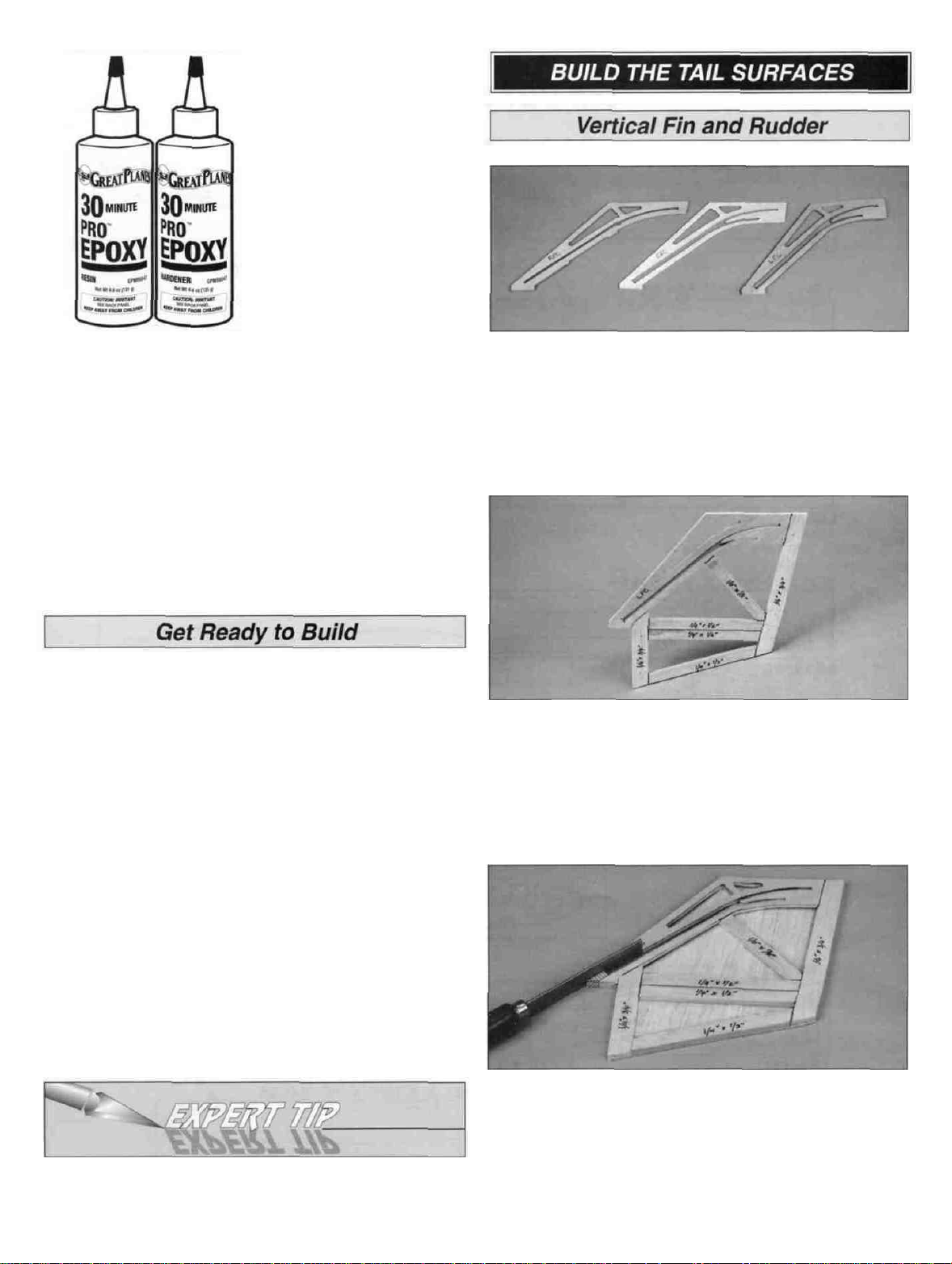
BUILD THE TAIL SURFACES...........................................8
Vertical fin and rudder
Stabilizer and elevators
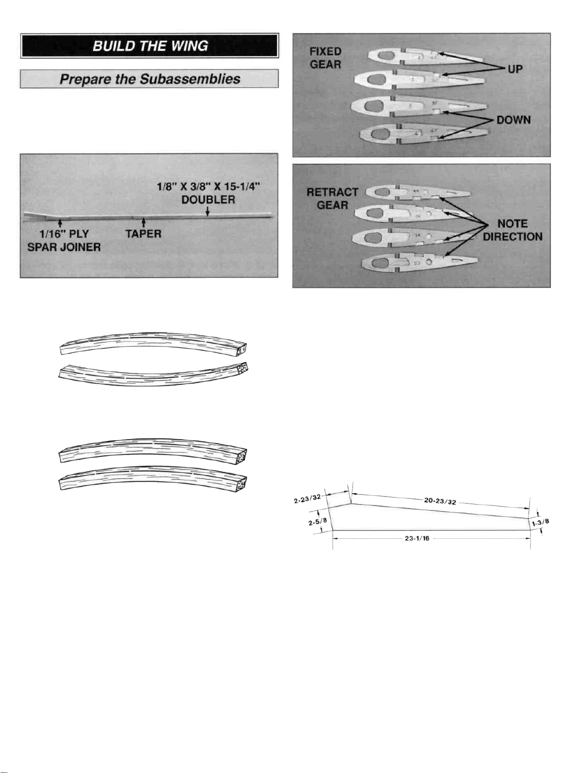
BUILD
THE WING
Prepare subassemblies.............................................11
Assemble the wings .................................................12
Completing the wing panels ......................................14
Join the wings............................................................16
Sand the leading edge ..............................................18
Assemble and install the tip tanks.............................18
BUILD THE FUSELAGE ................................................19
Frame the fuselage ...................................................20
Mount the engine ......................................................26
Install the canopy and cowl .......................................26
Mount the wing.............!............................................28
FINAL ASSEMBLY
Install the tail group ...................................................29
Assemble the engine nacelles...................................30
Balance the airplane laterally
FINISHING.......................................................................31
Fuel proofing .............................................................31
Final sanding before covering ...................................31
Applying MonoKote" covering ...................................31
Covering sequence ...................................................32
Painting .....................................................................32
Apply the decals . .....................................................32
INSTALL THE RADIO AND CONTROL SURFACES .....32
Install receiver and switch
Hinge and hook up the controls.................................33
Recommended control surface throws......................35
COMPLETE THE MODEL...............................................36
Install the
Install retractable
Install fixed landing gear............................................36
Install the nacelles and tip tanks
Balance the model
THE MAIDEN VOYAGE...................................................37
Balance the propeller ................................................37
Preflight .. . .. ............................................................38
Range check your radio ............................................38
Engine
AMA Safety Code......................................................38
fuel
safety
.......................................................3
.............................................................4
.................................................8
.............................................10
...........................................................11
..........................................................29
....................................30
.........................................32
tank
....................................................36
landing
precautions
fore
gear
..................................36
...............................37
and aft
.................................37
.........................................38
FLYING............................................................................39
Find a safe place to fly ..............................................39
Takeoff.......................................................................39
Flight......................................................................... 39
Landing......................................................................40
TWO VIEW DRAWING
Your Great Planes Learjet is not a toy, but rather a
sophisticated, working model that functions very much like an
actual airplane.
Because of its realistic performance, the Learjet, if not
assembled and operated correctly, could possibly cause
injury to yourself or spectators and damage property.
To make your R/C modeling experience totally
enjoyable, we recommend that you get experienced,
knowledgeable help with assembly and during your
first flights. You'll learn faster and avoid risking your model
before you're truly ready to solo. Your local hobby shop has
information about flying clubs in your area whose
membership includes qualified instructors.
You can also contact the national Academy of Model
Aeronautics (AMA), which has more than 2,300 chartered
clubs across the country Through any one of them,
instructor training programs and insured newcomer training
are available.
Contact the AMA at the address or toll-free phone
number below.
Congratulations! Thank you for purchasing the Great
Planes Learjet!
This Learjet is a sport model of the full-size Learjet 35A. It
was designed by noted Ultra Sport'" modeler Jim
Feldmann It's easy to build and fly, predictable, fairly
aerobatic and has no "bad habits," making it a great sport
airplane. Traditional Great Planes quality and ruggedness
is evident throughout this kit, making this an airplane you'll
want to take along every time you go to the flying field.
....................................................40
Academy of Model Aeronautics
5151 East Memorial Drive
Muncie, IN 47302-9252
Tele. (800) 435-9262
Fax (317) 741-0057
2
Page 3
This is not a beginner's airplane! While the Learjet is
fairly easy to build and flies great, we must discourage you
from selecting this kit as your first R/C airplane It can be
fast, highly maneuverable and lacks the self-recovery
characteristics of a good basic trainer such as the Great
Planes PT Series On the other hand, if you have already
learned the basics of R/C flying and you are able to safely
handle a "trainer" airplane, the Learjet is an excellent
choice to improve your skills and learn new maneuvers.
Please inspect all parts carefully before starting to
build! If any parts are missing, broken or defective, or if
you have any questions about building or flying this
airplane, please call us at (217) 398-8970. If you are
calling for replacement parts, please reference the part
numbers and the kit identification number (stamped on
the end of the carton) and have them ready when calling.
1. You must build the plane according to the plan and
instructions. Do not alter or modify the model, as doing so
may result in an unsafe or unflyable model In a few cases
the plan and instructions may differ slightly from the
photos In those instances you should assume the plan
and written instructions are correct
Engine And Mount
The recommended engine size range is as follows'
40 - .50 cubic inch displacement 2-stroke.
This kit includes a Great Planes EM2840 engine mount
that fits nearly all 2-stroke engines in the recommended
range If you prefer, you may purchase a custom engine
mount for your engine, or you may choose to install
shock-absorbing, rubber-cushioned mounts.
Fixed or retractable landing gear
The Great Planes Learjet includes prebent wire landing
gear for fixed installation To add to the sleek and realistic
appearance of your model in flight, you may want to
install retracts We have included instructions for both
installations However, you will need to purchase a set of
three mechanical retracts, two servos, and a "Y" harness
if you choose the retract option Pneumatic retracts may
be used in place of the suggested mechanical units if you
prefer
2. You must take time to build straight, true and strong.
3. You must use a proper R/C radio that is in first class
condition, the correct sized engine and correct
components (fuel tank, wheels, etc ) throughout your
building process.
4 You must properly install all R/C and other components so
that the model operates properly on the ground and in the air.
5. You must test the operation of the model before the first
and each successive flight to insure that all equipment is
operating, and you must make certain that the model has
remained structurally sound Be sure to check the nylon
clevises often, and replace if they show signs of wear.
6. You must fly the model only with the help of a
competent, experienced R/C pilot if you are not already
an experienced and knowledgeable R/C pilot at this time.
NOTE We, as the kit manufacturer, can provide you
with a top quality kit and great instructions, but ultimately
the quality of your finished model depends on how you
build it, therefore, we cannot in any way guarantee the
performance of your completed model, and no
representations are expressed or implied as to the
performance or safety of your completed model
Remember: Take your time and follow directions to end
up with a well-built model that is straight and true.
D Four or five channel radio with 4 to 6 servos
(optional retracts)
D 6" Servo extension cord
D Propellers (See engine instructions)
D 2-1/4" Jet spinner
(white GPMQ4542) (black GPMQ4540)
D 6 to 8 oz Fuel tank
(6 oz GPMQ4102 8 oz GPMQ4103)
D 2 oz Thin CA adhesive (GPMR6015)
D 2 oz Medium CA adhesive (GPMR6009)
D 1 oz Thick CA adhesive (GPMR6014)
D 6-Minute epoxy (GPMR6045)
D 30-Minute epoxy (GPMR6047)
D 1-3/4" Nose wheel (GPMQ4220)
D 2" Main wheels (GPMQ4221)
D 5/32" Wheel collars (6) (GPMQ4306)
D Model covering (2 - 3 rolls)
(Top Flite MonoKote" Covering)
D Medium fuel tubing (GPMQ4131)
D 1/2" thick Latex foam rubber padding (HCAQ1050)
D Sliver solder (recommended) (GPMR8070 w/flux)
D Switch & charge jack mount (optional) (GPMM1000)
D Fuel filter (optional) (GPMQ4150)
D Fuelproof paint
(see "Painting" section of instructions on page 32)
3
Page 4
D Tricycle retract gear - (HCAP4000)
D Retract servo (Futaba S136G or similar)
D Standard servo for nose gear retract
D Servo "Y" harness
D 1-1/4" x 5/32" Wheel axles (3) (GPMQ4280)
D 2-56 x 12" Threaded wire pushrods (2) (GPMQ3750)
D 2-56 x 36" Threaded wire pushrods (1) (GPMQ3716)
D Screw-Lock pushrod connector (3) (GPMQ3870)
D 4-40 x 1/8" Set screws
*ltems in parentheses (GPMQ1234) are suggested part
numbers recognized by distributors and hobby shops and
are listed for your convenience GPM is the Great Planes
brand, HCA is the Hobbico® brand, TOP is Top Flite
D Hand or electric drill *
D Drill bits 1/16", 3/32", 7/64" or #35, 1/8", #29 or
9/64", 3/16", #10 or 13/64", 15/64", 17/64" and 1/4"
D Sealing iron - (TOPR2100)
D Hot sock (optional) - (TOPR2175)
D Heat gun (optional) - (TOPR2000)
D Razor saw
D #1 knife handle - (XACR4305)
D #11 Blades - (HCAR0311 pkg of 100)
D Common and needle nose pliers
D Screwdrivers (phillips and flat)
D T-Pins - (HCAR5100 small, HCAR5150 medium,
HCAR5200 large)
D Straightedge - (Fourmost Non Slip FORR2149)
D Masking tape
D Sandpaper (coarse, medium, fine grit)
D Sanding blocks or Great Planes Easy-Touch"
Bar Sander (GPMR6170 -11" & GPMR6172 - 22")
D Waxed paper
D Lightweight balsa filler - (HCAR3401)
D 5/32" brass tube (optional)
D 1/8" brass tube (optional)
D Tap wrench
D 1/4-20 Tap - (GPMR8105 w/dnll bit)
D IsopropyI rubbing alcohol (70%)
D Dremel® Moto Tool® or similar w/sanding drum and
cutting burr (optional)
D Kyosho" curved scissors (optional) - (KYOR1010)
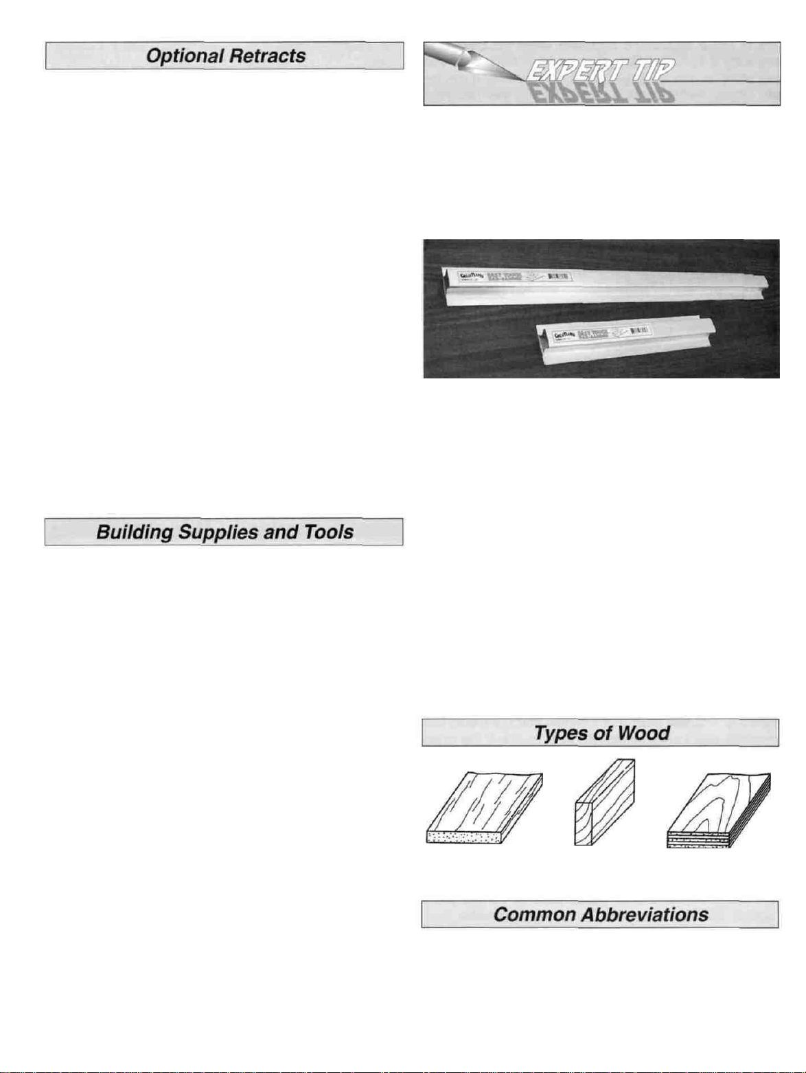
On our workbench, we have four 11" Easy-Touch Bar
Sanders, equipped with #50, #80, #150 and #220-gnt
sandpaper This setup is all that is required for almost
any sanding task Custom sanding blocks can be made
from balsa for sanding hard to reach spots We also keep
some #320-gnt wet-or-dry sandpaper handy for finish
sanding before covering
Great Planes Easy-Touch Bar Sanders are made from
light-weight extruded aluminum and can be found at
most hobby shops The sanders are available in two
sizes - 11" (GPMR6170) for most general purpose
sanding and 22" (GPMR6172) for long surfaces such as
wing leading edges We recommend using the 2-1/4"
wide self adhesive sandpaper sold in 12' rolls by Great
Planes The sandpaper is available in three different grit
sizes - #80-grit (GPMR6180), #150-grit (GPMR6183)
and #220-grit (GPMR6185) Standard sandpaper can be
attached by gluing it to the sander with rubber cement.
Apply the rubber cement to both the bottom of the sander
and the back of the sandpaper When both surfaces are
dry to the touch, press the sandpaper firmly onto the
sander Spray adhesive can be used for this purpose but
it's much harder to remove the sandpaper when you
need to replace it Use a knife blade for cutting
sandpaper, not your good scissors!
Balsa Basswood Plywood
Elev = Elevator
LE = Leading Edge (front)
Lt = Left
Rt = Right
TE = Trailing Edge (rear)
4
Fuse = Fuselage
LG = Landing Gear
Ply = Plywood
Stab = Stabilizer
" = Inches
Page 5
We understand that the caliber of modelers likely to build
the Great Planes Learjet may be rather high You may
already know all about the types of adhesives you like to
use However, due to its easy building features, many new
builders may try their hand at the Great Planes Learjet For
those modelers (experts may read along), we have
provided some explanation about the variety of adhesives
used during construction of a model.
Accelerator is a liquid chemical that
comes in a spray bottle for use in
speeding up the cure time of all CA
types It should be misted on, not
sprayed heavily on the joint Accelerator
may cause exposed CA to bubble and
sometimes change color If accelerator
is sprayed on too heavily it may weaken
the glue joint, so use it sparingly
Cyanoacrylate or CA glue has changed the way models
are built more than any other advance in modeling
technology In the good ol' days, model cement like
Ambroid, Duco, Comet and Sigment were the glues of
choice They all had a strong odor that could cause
dizziness, dried slowly (compared to CA) and became
brittle with age CA, on the other hand, is stronger, works
almost instantly and is bottled in three different viscosities
(thicknesses) CA is used for most glue joints, except where
epoxy is specified CA does emit rather strong fumes (some
say it's like tear gas) as it cures, so rule number one is to
work in a well ventilated area. All CA glues work best if
the joints are smooth and fit well.
Thin CA is also known simply as CA This
is the adhesive that has revolutionized
model building because it allows you to
assemble the parts first, then apply the
adhesive The thin formulation flows or
"wicks" into the joints and sets almost
instantly, eliminating the need to hold
things together while the glue dries You
will often use Thin CA for the initial bond,
then follow with medium or thick CA for
extra strength, especially when gluing
plywood or hardwood.
CA+ is also known as medium or gap
filling CA CA+ is used for surface
gluing, filling small gaps between poorly
matched parts and for general purpose
applications It cures slower than thin CA,
allowing you to apply a bead to two or
three parts before assembly Curing time
without accelerator is 20-30 seconds.
CA- or thick CA is used when extra
positioning time is needed CA- is a great
gap filler and is also used to make fillets
when a little extra strength is required.
Curing time is about 1-2 minutes.
A word about CA safety!
After applying CA, to avoid the puff of strong vapors,
don't stand directly over the work All CA glues will bond
skin almost immediately If this should happen, CA
Debonder (available from your hobby dealer) or acetone
fingernail polish remover will dissolve the CA if allowed
to soak into the bond for a few minutes Don't use
vigorous means to separate a skin bond Never, never
point the CA applicator tip toward your face' Be
especially careful when opening a clogged tip In case of
eye contact, flush thoroughly with water, then seek
medical attention, but don't panic. Please, keep CA
(and all other modeling chemicals) out of the reach
of children!
Epoxy
Great Planes has two epoxy formulations available for the
modeler Both offer exceptional strength and convenient
working times Use epoxy when the joint requires
exceptional strength, such as when installing the firewall,
when joining the wing panels, and when installing wing
hold-down blocks As with most epoxies, you mix equal
parts of resin and hardener, stir well then apply a thin film
to each part Parts should be clamped, pinned, taped or
weighted in place until fully cured Before the epoxy cures,
clean off any excess with a paper towel A word of caution
about mixing epoxy-don't use extra hardener in the
hopes of making the mixture harder or work faster Just
about all epoxies work best with exactly a 50/50 mix When
you increase the amount of hardener, you run the risk of
causing the cured epoxy to become either brittle or
rubbery-neither being as strong as a properly mixed batch.
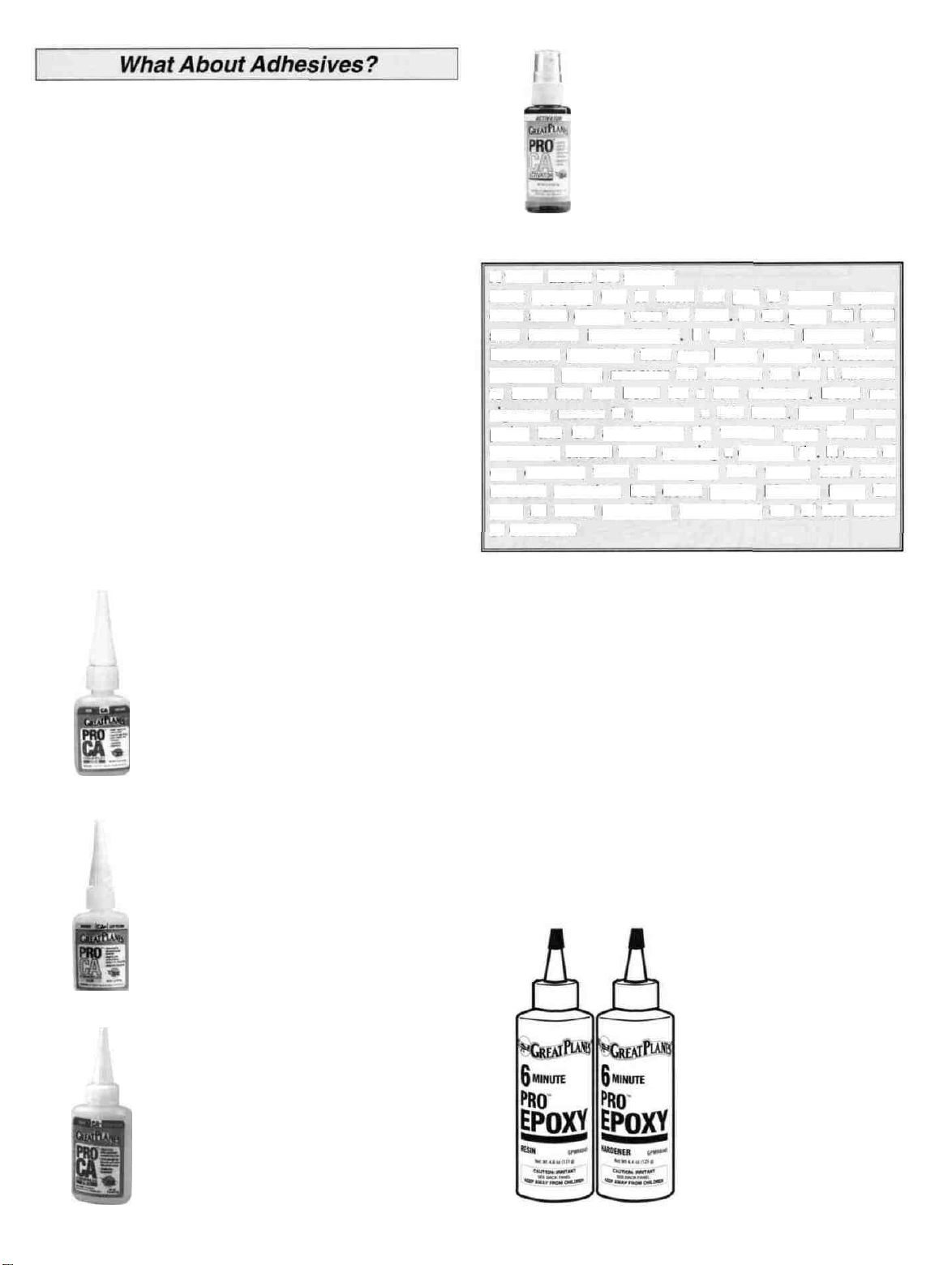
6-Minute Epoxy is used
for simple, small gluing
applications where
elaborate alignment is not
required Working time
(before its too gooey to
use) is about 5 minutes,
handling time 15 minutes
and it's fully cured in about
1 hour
(Continued on page 8)
5
Page 6
6
Page 7

7
Page 8
30-minute epoxy is used
for extra strength (because
it can penetrate longer) and
where several parts must
be aligned and checked
before it cures. Working
time is about 25 minutes,
handling time 2 hours, and
it's fully cured in 8 hours.
Great Planes Pro" Wood Glue is an Aliphatic resin glue
that works well on all types of wood. It is non-toxic, virtually
odorless and dries clear. Some people are sensitive to CA
and epoxy fumes, so this is a good alternative for general
modeling use. Its only drawback is that it is slow to cure,
requiring the parts to be securely clamped, pinned or taped
while the glue dries.
Okay, you've got your work space ready, your tools are at
hand, and you know how to choose and use the right glue
for the job. Let's get started!
D 1. The fin core is made up of left and right die-cut 1/8"
plywood fin cores (LFC, RFC) and a die-cut 1/16" balsa
center fin core (CFC). Place the fin plan on your building
board and cover it with waxed paper. Place the 1/8" RFC
(with one slot) over the plan and glue the 1/16" center fin
core on top of it. Glue the 1/8" LFC (two slots) on top of the
center fin core.
D 1. Unroll the plan sheets. Reroll the plan sheets inside
out to make them lie flat.
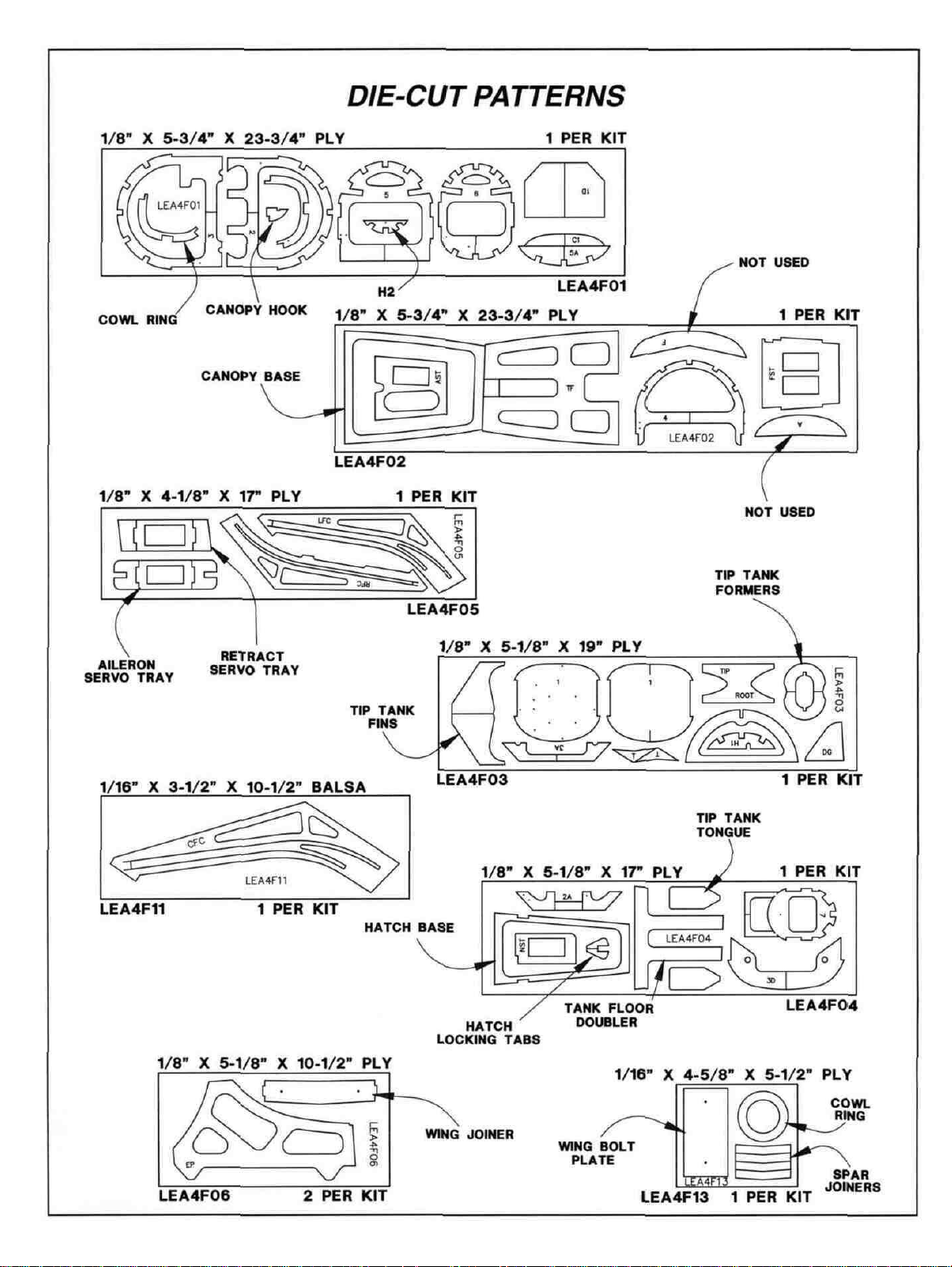
D 2. Remove all parts from the box. As you do, determine
the name of each part by comparing it with the plan and the
parts list included with this kit. Using a felt-tip or ball point
pen, lightly write the part name or size on each piece to
avoid confusion later. Use the die-cut patterns shown on
pages 6 and 7 to identify the die-cut parts and mark them
before removing them from the sheet. Save all scraps. If
any of the die-cut parts are difficult to punch out, do not
force them! Instead, cut around the parts with a hobby
knife. After punching out the die-cut parts, use your T-Bar
or sanding block to lightly sand the edges to remove any
die-cutting irregularities.
D 3. As you identify and mark the parts, separate them
into groups, such as fuse (fuselage), wing, fin, stab
(stabilizer), and hardware.
Zipper-top food storage bags are handy to store your parts
as you sort, identify and separate them into subassemblies.
D 2. Sand the front and top edges of the fin core smooth,
then pin the core over the plan. Assemble the balsa fin
framework from 1/4" x 1/2" and 1/4" x 3/4" balsa sticks on
the core as shown on the plan. Note: The frame is thinner
than the fin core but this will not cause a problem. Do not
install the leading edge, dorsal fin or the 3/8" top and rear
pieces yet.
D 3. Remove the fin from the board, sand both sides
smooth (it's OK if the plywood core is a little thicker than
the balsa framing). Sheet the right side with 1/16" balsa
sheeting. Drill a 1/8" hole through the sheeting at the rear
end of the top slot and elongate the hole to fit the control
cable tubing. Cut away the fin core below the bottom of the
slots as shown on the plan.
8
Page 9
D 4. Cut three pieces of inner pushrod tube to match the
plan. Fit the right elevator cable tube in the top slot of the
fin core, up against the sheeting on the right side, with an
inch or so extending through the sheeting hole.
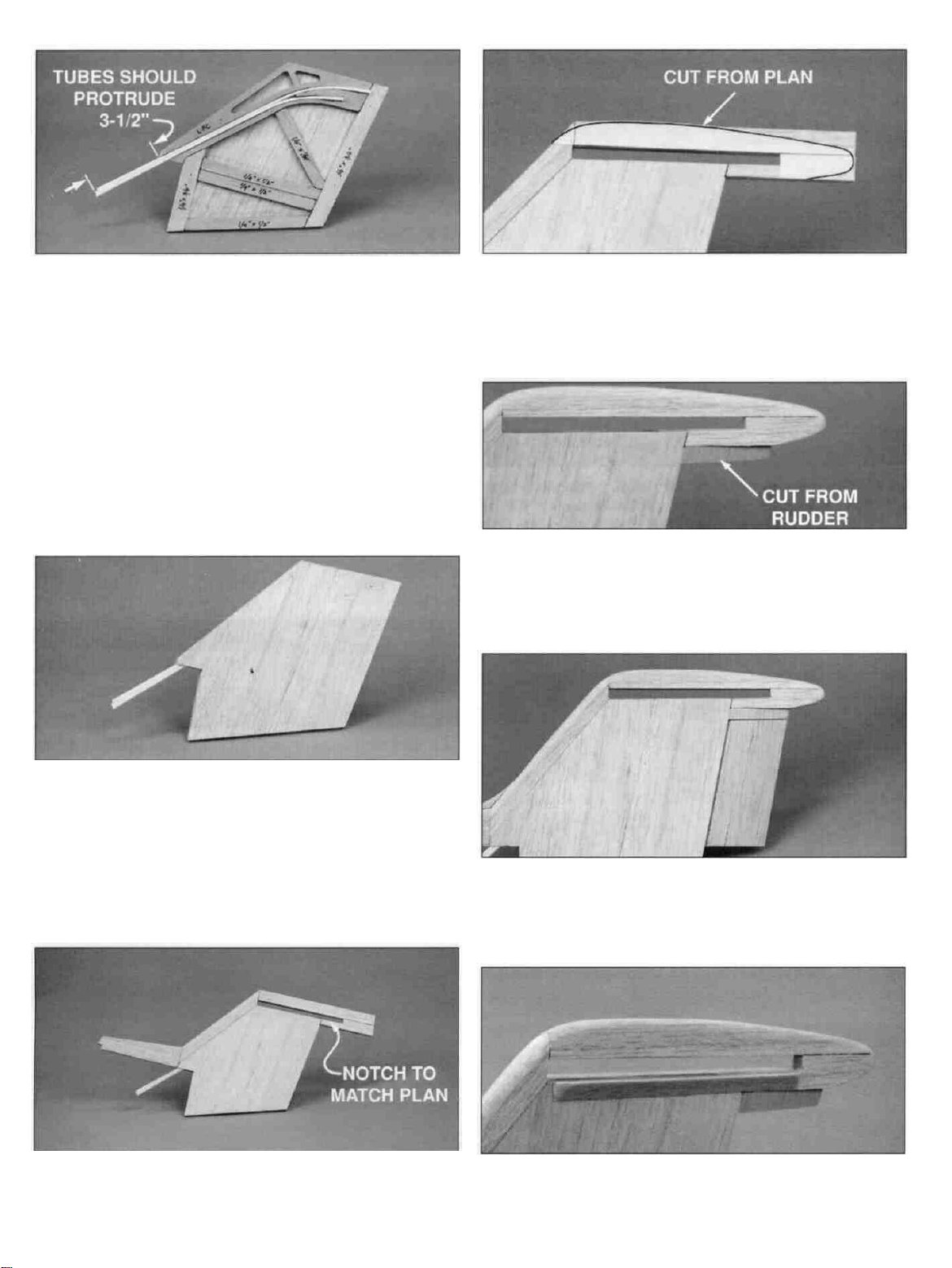
NOTE: LEAVE 3-1/2" OF ALL THREE TUBES
EXTENDING PAST THE BOTTOM OF THE FIN CORE. Fit
the left elevator cable tube in the same slot on top of the
right one, but have it exit on the left side. Fit the rudder
cable tube in the lower slot in the fin core exiting on the
left side as well. When you're happy with the fit, use thick
CA to hold the tubes in the slots.
D 7. Cut the fin top pattern from the plan, then glue it to
the top of the fin with spray adhesive or rubber cement.
Sand the edges of the fin top to match the pattern. Round
the top of the dorsal fin, front of the leading edge and top of
the
fin
top.
D 8. Sand one end of the shaped balsa rudder to match
the angle shown under the stab on the plan. Cut a 3/8"
piece from the sanded end to make the rudder filler. Glue
the 3/8" piece to the bottom of the fin's TE. Cut the rudder
to match the size and shape shown on the plan.
D 5. Sand the right elevator tube flush with the sheeting,
then pin the fin assembly back on the building board. Add
1/16" balsa sheeting on the open side, fitting the sheeting
around the rudder and left elevator tubes where they exit.
Sand the tubes flush with the sheeting.
D 6. Add the 3/8" x 3/4" balsa stick leading edge, trailing
edge (TE), top (notched to match the plan) and shaped
dorsal fin. Remove the assembly from the board.
D 9. Sand a "V" on the leading edge (LE) of the rudder to
match the cross-section on the plan. Use masking tape to
temporarily attach the rudder to the fin. The hinges will be
installed after covering.
D 10. Round the ends of two 6" long pieces of 3/8" balsa
tri-stock and glue them to the sides of the fin, flush with the
bottom of the stab slot.
9
Page 10
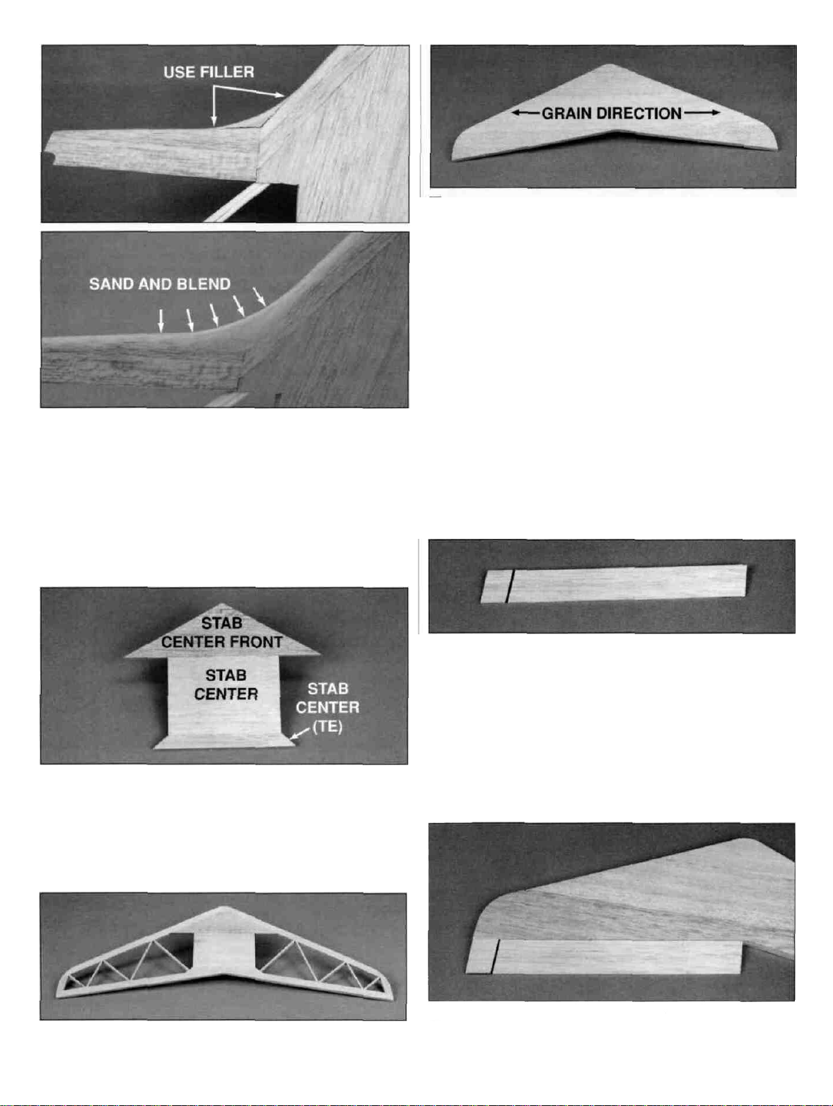
D 11. Cut a small piece of 3/8" scrap balsa stick to fit
between the top of the dorsal fin and the vertical fin. Shape
and sand this piece to match the plan. Use balsa filler
(HCAR3104).
Stabilizer & Elevators
D 3. Sand the completed framework smooth, then glue
1/16" x 3" balsa sheeting to the top surface.
D 4. Remove the stab from the board. Sand the bottom
side smooth, then sheet it with 1/16" x 3" balsa. Trim the
perimeter to the shape shown on the plan and sand the
assembly smooth. Sand the leading edge and tips round to
match the cross section on the plan but leave the TE flat.
D 1. Put the stab plan on your building board and cover it
with waxed paper. Pin the 1/4" shaped balsa stab center
front over the plan, then glue the 1/4" x 3" x 4-1/4" balsa
stab center to its aft edge. Cut the stab center (TE) from a
1/4" x 1/2" balsa stick to match the shape shown on the plan.
D 2. Assemble the stab frame from 1/4" x 1/2" balsa sticks,
then cut and glue the 1/8" x 1/4" balsa trussing in position.
D 5. Cut both ends of each shaped balsa elevator to the
angle shown on the plan, then cut a 1" piece from each
one. Glue these short pieces to the TE of the stab at the
tips, and sand to shape.
D 6. Sand a "V" on the LE of the elevators and trim the
inner ends to match the plan. Temporarily attach the
elevators to the stab with masking tape.
10
Page 11
D 1. Pin the wing plan to your building board and cover it
with waxed paper.
TWO WARPED SPARS INSTALLED
THIS WAY WILL RESULT IN A
STRAIGHT WING
TWO WARPED SPARS INSTALLED
THIS WAY WILL RESULT IN A
WARPED WING
D 2. Assemble the spars as follows: Pin one of the 1/4" x
3/8" x 30" balsa main spars down over one wing plan and
trim the outboard end at the centerline of W-9 (save the
off-cut piece for use in a moment). Locate a 1/8" x 3/8" x
15-1/4" balsa spar doubler. Sand 2-1/4" of one end of the
spar doubler to a taper (see plan). Glue the spar doubler to
the inboard end of the main spar so that the untapered end
is flush with the root end of the main spar. Trim the
off-cut piece of 1/4" x 3/8" to match the plan at the outboard
end of the main spar, then glue it in position. Glue the diecut 1/16" plywood spar joiner on top of the joint.
D 3. Remove this spar from the plan, then assemble a
second one over the same plan.
D 5. Decide whether you will be using fixed or retractable
landing gear. The rib doublers required for fixed or retract
gear are different. W-3F and W-4F are used for the fixed
gear and W-3R and W-4R are used for the retract gear.
Glue the appropriate doublers to the W-3 and W-4 ribs,
being sure that you make a left and a right of each one.
Cut the gear block notches out of each rib using the
notches in the doubler as a guide.
D 6. Align the shaped and notched leading edges (LE)
over the plan. Cut the LE in two at the centerline of W-9.
Save both pieces.
CUT LE SHEETING AS SHOWN (4 REQUIRED)
D 7. Using the plan and the pattern shown above, cut four
3/32" x 3-1/2" x 30" balsa LE sheets. Note: The aft edge of
the sheets should fall approximately along the middle of
the spar.
D 8. Glue the two die-cut plywood dihedral braces (DB)
together with 6-minute epoxy. Be sure they are perfectly
aligned along all edges. Clamp the pieces together while
the epoxy cures.
D 4. Build two more spars over the plan of the other
wing. This procedure will produce left and right top and
bottom spars.
D 9. After the DB epoxy has cured, lightly sand the edges
to remove any bumps. Drill a 1/4" hole through the DB
at each of the two punch marks. These holes are for the
wing dowels.
11
Page 12
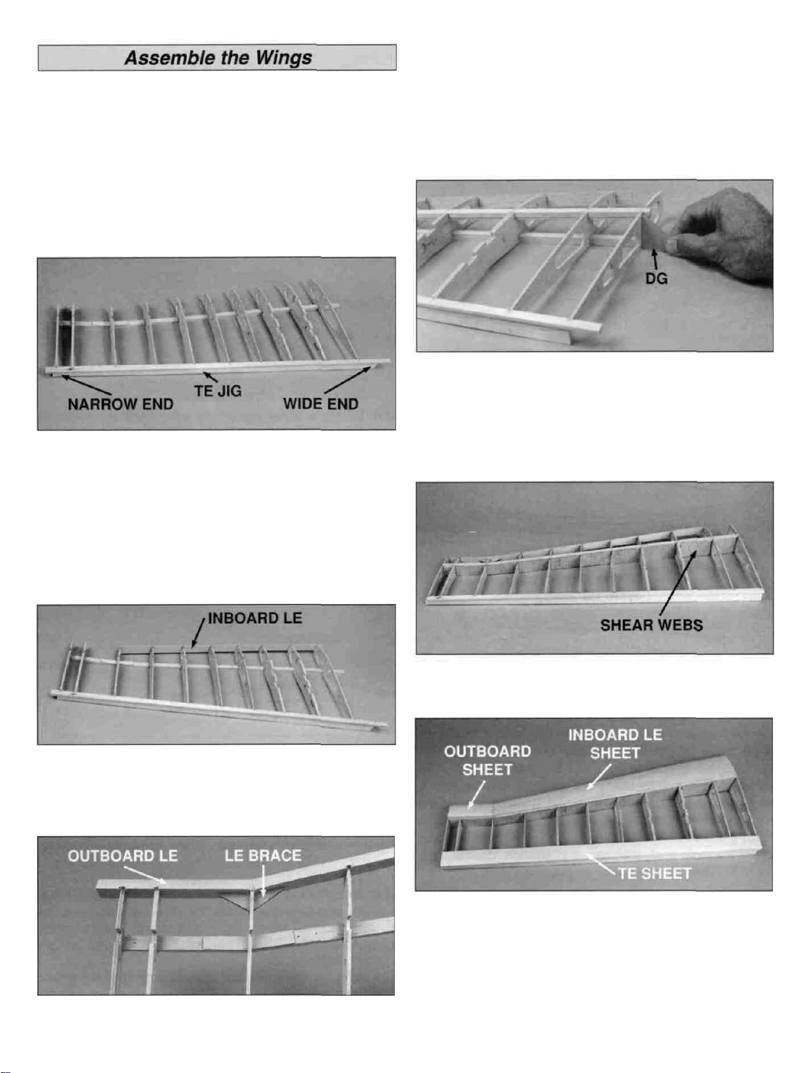
NOTE: The wings are built UPSIDE DOWN over the
opposite wing plan.
glue it in place on the forward edge of ribs W-9 through
W-11. Glue the die cut 1/8" plywood leading edge brace to
the back of the leading edge at W-9.
D 1. Start with the wing plan which shows your chosen
landing gear. Pin the trailing edge support jig to the board
over the plan, under the waxed paper. The wide end of the
jig is positioned at the root end of the wing.
D D 2. Carefully separate the leading and trailing edges
with a hobby knife.
D D 3. Pin the bottom spar down and glue W-2, W-6 and
W-11 to the spar, then glue the shaped and notched
trailing edge to those ribs. The ribs should be centered
vertically on the trailing edge and the trailing edge must be
kept level. (Since the trailing edge is tapered, it does not sit
flat on the support jig.) Pin the trailing edge to the support
jig. Add the rest of the ribs (except W-1). Be sure that the
rib doublers are on the correct side of W-3 and W-4 as
indicated on the plan.
D D 6. Fit and glue the second spar in position.
D D 7. Place W-1 in position (with the servo opening
pointing toward the building board) and hold the dihedral
gauge against the outer face to set the proper angle. Glue
W-1 in place. Cut both spars and the TE flush with W-1.
Trim the LE flush with W-2.
D D 4. Fit the inboard leading edge in place on ribs W-4
through W-9. The leading edge must extend an equal
amount above and below the ribs. Glue the leading edge in
place with thin CA.
D D 5. Sand the outboard leading edge (the short piece
you cut off) to fit against the inboard leading edge, then
D D 8. Fit and install 1/16" balsa shear webs in all rib
bays against the aft edges of the spars.
Refer to this photo for next three steps.
D D 9. Lightly sand the top of the ribs, spar and trailing
edge to remove any irregularities. Sand the forward edge
of the 3/32" inboard leading edge sheeting to match the
angle made by the ribs and the leading edge. The aft edge
of the sheet should fall on the centerline of the spar. When
satisfied with the fit, glue it in place.
12
Page 13

D D 10. Fit and glue the 3/32" x 1-1/4" x 30" trailing edge
sheeting in position across the aft edge of the wing.
D D 11. Sheet the outboard leading edge with the balsa
you trimmed off when cutting the LE sheets. Glue it in place.
D D 12. Slide the die-cut 1/8" ply tip tank tongue in place
through the slots in W-11 and W-10. Fit a 1/4" x 27/32" x 1"
balsa tip tank retainer block on top of the tongue between
W-10 and W-11 and carefully glue it to the two ribs.
Remove the tongue immediately so that you don't
accidentally glue it to the block. Glue a piece of scrap 3/32"
balsa on top of the hardwood block and sand it to match
the shape of the ribs.
D D 15. Fit the retract mechanism in place, trimming the
plywood mounting plates as required to allow the retract
to function properly. Drill 3/32" mounting holes and
temporarily install the retract with four #4 x 3/8" sheet
metal screws.
D D 13. Cut and install the tip sheeting (from left over
3/32" balsa) between W-10 and W-11.
Use the instructions that follow to install the landing gear
mounting rails of your choice (for fixed or retractable).
D D 14. Use 30-minute epoxy to glue the 1/4" x 3/4" x
3-5/8" plywood retract mounting plates into the slots in
W-3 and W-4.
D D 16. Use 30-minute epoxy to glue the 7/16" x 5/8" x
4-5/16" hardwood main gear block into the notches in W-3
and W-4. The inboard end should overhang W-3 by 3/4"
and the "groove" faces away from the building board.
D D 17. Use 30-minute epoxy to glue the 5/8" x 5/8" x 5/8"
hardwood landing gear torque block to the ungrooved side
of the main block, against the root face of W-3F. Glue the
5/8" wedge shaped landing gear gusset on the ungrooved
side of the main block, against the root face of W-4F with
30-minute epoxy.
13
Page 14

D D 18. Drill an 11/64" hole through the main gear block
and the torque block as shown on the plan. This hole must
be drilled perpendicular to the main gear block and parallel
to W-3F.
D D 19. Fit the 5/32" music wire strut into the blocks and
fill the unused slot at either end of the main block with
scrap balsa. Remove the strut.
D D 20. Remove the wing from the board and check all
glue joints. Add a glue fillet to any joint that needs it. Sand
off any imperfections before proceeding.
D D 26. Cut and glue 3/32" x 3/8" balsa cap strips to the
top of ribs W-5 through W-9.
D D 27. Sheet the wing center section with 3/32" x 3"
balsa cut from a 36" sheet.
D D 28. Remove the wing from the board and sand the
sheeting flush with W-1, W-11 and the trailing edge. Rough
sand the leading edge to shape.
D D 21. With the wing "right side up," pin (or weight) the
spar to the building board. Tack glue the die-cut 1/8" ply TE
jigs, J1 and J11, to the bottom of the TE at ribs W-1 and W-
11. Pin or weight the aft portion of the wing to be sure the TE
jigs and main spar are touching the building board. Add a 5/8"
shim of balsa under the trailing edge center to prevent the TE
from bowing downward.
D D 22. Glue the top 3/32" x 1-1/4" x 30" balsa TE sheet
in position.
D D 23. Glue the inboard and outboard LE sheeting in
position. Be sure the TE jigs, shim and spar remain in
contact with the building board.
D D 24. Insert the tip tank tongue and fit a 1/4" x 27/32" x
1" hardwood upper retainer block on top of the tongue
between W-10 and W-11. Glue this block between the ribs,
and remove the tongue immediately. Glue scrap balsa to the
top of the block, then sand it to match the top of the ribs.
D D 25. Install the 3/32" tip sheeting (from left over
3/32" balsa).
D D 29. Turn the wing panel over and sheet the bottom
center section with 3/32" x 3" balsa. The sheeting must be
fitted around the main gear block or the retract mechanism
if using retracts.
Okay, clean up your building board, then build the second
wing panel over the other wing plan.
D 1. Cut a 3" piece from each 21" long tapered balsa
aileron. Check that the taper of the aileron stock matches
the shape of the airfoil. Glue the 3" pieces to the aft edge
of each wing panel, at the tip.
14
Page 15

D 2. Check that the taper of the 1 -3/8" x 6" balsa center
TE piece matches the shape of the airfoil.
NOTE: When installing the center trailing edge pieces
make sure they line up with the top and bottom surface of
the wing.
If necessary, sand the aft edge of the wing to correct the
problem. Trim and sand the ends to match the angles on
the wing plan. Cut a notch in the top surface of a balsa
center TE piece 1/2" from the root end. Fit an aileron
torque rod assembly into the groove with the threaded end
protruding through the notch. Prepare another center TE for
the other wing panel. Be sure to make a left and a right
side as shown.
D 4. Cut the ailerons to fit between the center TE and the
tip TE. Hold the aileron in position, then mark the location
of the torque rod arm. Drill a 1/8" hole, 3/4" deep, into the
LE of the aileron at the mark. Cut a groove for the torque
rod to fit into the aileron's LE. Sand the leading edge of
both ailerons to a "V" as shown on the plan.
D 5. Finish cutting out the aileron servo opening (and
retract servo opening if using retracts) that is partially
die-cut in both W-1 ribs. Mark the location of the servo
opening(s) on the top surface of both wing panels but don't
cut out the sheeting until after the wing has been joined.
D 3. Sand the mating root surfaces of the center TE pieces
to allow for the dihedral angle. Roughen the nylon torque
rod tubes with coarse sandpaper, then apply a dab of
petroleum jelly to the exposed wire at both ends of the
tube. Use 6-minute epoxy to glue the nylon torque rod
tubes into the center TE, then, before the epoxy cures, glue
the center TE assemblies to the aft edge of each wing at
the root with the threaded ends protruding through the top
of the wing. Be sure that the taper of the trailing edge
matches the shape of the airfoil.
D 6. Insert the landing gear strut wire into the retract
mechanism. Measure and cut the main retract struts to
4-7/16" long (measured from the surface of the wing).
Install the 2" main wheels (not included, GPMQ4221)
using adjustable 1-1/4" x 5/32" wheel axles (not included,
GPMQ4280) and 5/32" wheel collars (not included,
GPMQ4306). Verify that there is no toe-in or toe-out when
the retracts are extended, then tighten the locking screws.
15
Page 16

D 7. Slowly retract each strut and wheel, cutting away
the bottom center sheeting and ribs for clearance as you
go. Enlarge the diameter of the wheel well hole to 2-1/2"
keeping the hole centered on the retracted wheel.
D 2. If needed, sand the leading edge sheeting even with
the front edge of W-1.
D 8. The wheel well liners can be made from proper
sized foam or paper coffee cups, or from vertical grain
1/16" balsa sheeting wrapped around an appropriately
sized glass jar and glued to form a cylinder. Glue the
wheel wells in place, then trim the edges to match the
bottom sheeting.
D 9. Use a 12" long x 1/4" drill bit to drill a hole from the
retract servo opening, through the wheel well liners, to
the retract mechanism.
D 3 Before using any glue,trial fit the wings together using
the die-cut plywood dihedral brace (DB). The wing roots
(W-1) should fit together smoothly, and the dihedral brace
should contact both spars and also locks into both W-2s.
The dihedral brace is mounted perpendicular to W-1, not
parallel to the spars (see plan for exact position) Be sure
the "V" shaped edge of the dihedral brace is toward the
bottom of the wing. Apply 30-minute epoxy to the mating
surfaces of the W-1 ribs, dihedral brace and inner edges of
the center TE. Clamp or pin the wings together while the
epoxy cures.
NOTE: When the epoxy has cured, look at (DB) from the
leading edge and add additional epoxy to fill any visible gaps.
D 1 Finish cutting out the partially die-cut section
between the spars on both W-1 ribs.
D 4. Fit and install the 1/2" x 1-7/16" x 5" balsa center
leading edge block. We suggest using a liberal amount of
thick CA when you glue it in position.
16
Page 17

D 5. Draw a horizontal line across the front of the center
leading edge block. Mark the centerline of the wing on the
front of the block. Make a mark 1-3/4" on each side of the
centerline. These marks show the position of the 1/4" wing
dowels. Drill a 17/64" hole through the block at each of
the marks.
D 6. Carve and sand the top and bottom edges of the
block to follow the airfoil contour but leave the front
surface flat.
Applying Fiberglass Cloth
A. Center one end of the fiberglass cloth on the trailing
edge of the wing, then apply several drops of thin CA to
hold it in position. Roll the loose end of the fiberglass cloth
onto a pencil, then use the pencil as a handle to stretch
the cloth over the wing toward the leading edge. Apply a
few more drops of thin CA to the LE to hold the cloth in its
"stretched tight" position.
B. Make a squeegee by wrapping a 2" wide piece of stiff
cardboard with a plastic sandwich bag or similar material.
Perform the following operation in a well ventilated
area with a fan directing air flow away from you.
C. Starting at the trailing edge, flow thin CA into the cloth.
Smooth the cloth down with the squeegee as you work
toward the leading edge. Avoid standing directly over the
work as the CA fumes can be quite irritating to your eyes
and nose.
D. Allow the CA to cure naturally without using any
accelerator. When thoroughly cured, lightly sand the
edges with 150-grit sandpaper to remove any ridges.
E. Just before you cover your model, fill the weave and
blend the edges with the wing using balsa filler. Sand the
dried filler with 220-grit sandpaper and recoat if necessary.
D 7. Round one end of each 1/4" x 4" wing dowel and
chamfer the other end (to make it easier to insert). Test fit
the dowels into the wing to be sure that they pass easily
through the leading edge block and the dihedral brace.
Glue them in place with 30-minute epoxy.
D 8. Apply 3" wide fiberglass cloth to the center joint on
the top and bottom of the wing. We prefer to adhere the
cloth with thin CA to save weight, but resin or thinned epoxy
will work just as well. Read the Expert Tip that follows
before performing step #8.
D 9. NOTE: The aileron and retract servo trays are slightly
different in size - the aileron servo tray is the smaller one.
Center the die-cut plywood aileron servo tray on top of the
wing at the marks you made in siep 5 of the previous
section (Completing the wing panels). Mark the outside
perimeter of the tray, then cut the wing sheeting from inside
the lines. Refer to the wing plan to locate the retract servo
tray opening. Mark and cut the sheeting for the retract
servo tray.
17
Page 18

D 10. Insert the die-cut 1/8" plywood aileron servo tray
supports into the opening on the top of the wing, then fit
the servo tray onto the supports. Glue the assembly to the
inside of the wing with thin CA followed by a fillet of thick
CA. If installing retracts, repeat this operation for the die-cut
1/8" ply retract servo tray.
D 1. Trim the four plastic tip tank halves to the embossed
cut lines.
NOTE: Each piece has one half of a lap joint.
D 2. Sand the edges smooth. Roughen the inside surface
of the wing tip recess with coarse sandpaper.
D D 3. Carefully cut out the plastic from the inside of the
slot in the middle of the rib recess.
D D 4. Insert a die-cut ply tip tank former into the notches
of the tank rib. Insert the die-cut tip tank tongue (tapered
end first) through the rib slot into the notch of the former.
Align all parts "straight and true," then securely glue
them together.
D 11. Draw a center line on the die-cut 1/16" plywood
trailing edge reinforcing plate across the narrow
dimension. Glue the plate to the bottom of the wing, with
the centerlines on the wing and plate in alignment. Be sure
the punch marks are on the side that shows. You will need
to see them later.
1. Use the die-cut plywood leading edge gauge to check
the curvature of the LE along its length. The wide end of
the gauge is used at the root and the narrow end is used at
the tip. If necessary, touch up the LE with a sanding block
to conform to the gauge.
D D 5. Insert the tip tank tongue through the slot in the
tank and test fit the assembly on the wing tip. Be sure to
match the right tank with the right wing tip and the left
tank with the left wing tip.
D D 6. Remove the wooden support assembly, then apply
6-minute epoxy to only the rib. Slide the tongue back into
position through the tank (while on the wing) and allow the
epoxy to cure. Do not get any epoxy onto the tongue as the
tank must be removable.
18
Page 19

D D 7. Hold the tank in position while you carefully drill a
3/32" hole through the center of the mounting blocks and
tank tongue from the bottom of the wing. Try not to drill
through the top of the wing.
D D 8. Enlarge the opening of the entrance hole to 3/16"
diameter x 1/8" deep. This will hide the head of the cap
screw when it's installed.
D D 9. Glue the outside of the tip tank to the assembled
inner half.
D D 10. Cut a 1/8" wide slot in the "outside" aft end of the
tip tank centered between the top and bottom edge of the
tank. Test fit the die-cut plywood tip tank fin into the slot.
Round off the LE and TE of the fin with sandpaper.
D 1. Pin the side view fuselage plan to your building board
and cover it with waxed paper. Assemble the die-cut 1/8"
balsa front and rear fuselage sides over the plan, then
add the die-cut 1/8" balsa front and rear doublers.
D 2. Turn the fuselage side upside-down, cover it with
waxed paper, then assemble the fuselage side and its
doublers over it. Remove both sides from the board and
sand them so they match exactly. Cut 1/8" off the front of
the right side only. This will set the proper amount of right
thrust in the firewall.
D 3. Mark the former positions on the inside of both fuselage
sides, then remove the side view plan from the board.
D 11. Glue the fin into the slot at the aft end of the tank,
then repeat steps 2 thru 9 for the other tip tank.
D 12. If you will be painting the tip tanks, fill the joints with
automotive body filler (Bondo®). When the filler has cured,
wet sand the seam smooth.
This completes the assembly of the wing for the time being.
Looks like a jet wing, eh? Clean off your workbench, take a
break, then let's get on with the fuselage. You can sleep later.
D 4. Assemble the three piece firewall (with the punch
marks forward) using 6-minute epoxy. Glue the two F-1s
together and also F-1D to the aft side of the F-1s. Using the
plan and punch marks as guides, carefully drill holes for
the engine mount, fuel lines, throttle cable and, if using fixed
gear, the nosegear steering cable. Mark the top front of the
firewall now, so you won't make a mistake later. Install four
4-40 blind nuts on the back of the firewall assembly.
19
Page 20

d 5. After referring to the fuselage plan, drill the
pushrod guide tube holes at each of the punch marks on all
of the formers. Use a 1/8" drill bit for the nosewheel
steering guide tube and a 3/16" bit for the outer throttle
guide tube.
NOTE: Do not drill any holes in F-7 at this time.
(Assembles right side-up over the plan)
Note: The firewall is lower than the bottom of the fuselage
sides, so in order to install it at the proper time, the
fuselage must be built with the nose extending beyond
the left side of your building board. Pin the fuselage top
view plan to the board, with F-1 extending about an inch
past the edge of the board.
Important: Unless specified differently, all fuselage formers
are made from die-cut 1/8" plywood. Be sure that the die
stamped numbers on each former face the nose of the
model or the pushrod routing holes will not line up.
D 1. With the right fuselage side held flat on your building
board, glue F-3 in place, perpendicular to the fuselage side.
Be careful, when installing all of the fuselage formers, that
you position them correctly (see plan).
D 4. Pull the rear of the fuselage sides together and hold
them with rubber bands. Glue F-7 into place and pin the
support leg on the bottom of F-7 to the board, again making
sure that the former is centered over the plan.
D 5. Cut a 1" length from the 1/4" x 3/4" balsa left over
from the fin frame. Taper it to a wedge shape to fit between
the fuse sides at the aft end of the fuse. Remove the rubber
bands holding the rear of the fuselage sides together and
place the wedge between the sides. Measure carefully
with a 90 degree triangle to be sure the aft ends of the
sides are directly above the centerline shown on the plan,
then glue the wedge in place with thin CA. Trim the top and
bottom of the wedge flush with the fuse.
D 6. Glue in formers F-6 and then F-5, centered over the
plan and pinned to the board. Pin the fuselage sides to the
board at F-5.
D 2. Turn this assembly upright and pin F-3 in its proper
location over the plan, then glue the left fuselage side to
F-3. NOTE: All formers have a centerline embossed on the
bottom end. Use these marks to align the formers over the
fuse plan.
D 3. Glue F-4 in place between the fuselage sides. Be
sure to seat F-4 all the way to the top of the "long" notch.
D 7. Hold the front of the fuselage sides together with
rubber bands while you glue F-2 in place. Slide the die-cut
1/8" ply tank floor into position with the embossed letters
pointing toward the top of the fuse. Glue the tank floor to
F-2 only - not to the fuse sides. (See next photo.)
D 8. Fit the firewall assembly between the front of the
fuselage sides. Sand an angle on the edges of the firewall
to match the angle of the fuselage sides when they are
20
Page 21

pulled in to meet it Wet the fuselage sides from F-2
forward, but keep the water away from the gluing surfaces.
Glue the firewall in place with 30-minute epoxy, then run a
bead of thick CA along the top edges of the tank floor Use
rubber bands or clamps to hold the sides together until the
epoxy cures Pin the fuselage sides to the board as close to
the firewall as you can to help keep the firewall centered
D 9 Without gluing, fit the 1/4" x 1/4" x 36" balsa top
stringers in the notches from F-2 to F-7 Mark the position
of F-4 on each stringer Cut halfway through the stringers
from the bottom so that they will make a clean bend at F-4
Glue all five stringers in place
D 11 Install the 3/32" x 3" x 13-1/8" forward top sheeting
from F-2 to F-4 Glue the first sheet to the top of the
fuselage side doubler and then trim it so that it extends to
the middle of the second stringer Wet the balsa if
necessary, then glue this sheet down Sheet the other
side. Fit and install the top sheet between them.
D 12 Install the 3/32" x 3" x 19-1/8" aft top sheeting the
same way as the forward sheeting, except that you may
find it easier to trim the side sheets roughly to shape before
gluing them to the top of the fuse doubler.
D 10 Center, then glue the 3/32" x 1-1/16" x 2" balsa
fillers between the stringers on both sides of F-4 Sand the
front and rear portions of the fillers and the tops of the
stringers so that the sheeting will lie flat on top of them
Sheeting a rounded surface.
Wet the outside of a balsa sheet, then flex it with the
grain for a minute or two to soften it up and start a curve
Align the sheet with the fuse side, then temporarily hold it
in place with clothespins
Mark the sheet for cutting Always trim the sheet to the
center of the appropriate stringer to allow for a gluing
surface for the next piece of sheeting
Apply medium or thick CA to all frame parts that the
sheet will contact. Roll the sheet into position, starting
along the lower edge Hold it in position by hand and with
clothespins until the CA cures Wick thin CA along the
top seam, wiping off the excess before it cures Repeat
for the other side of the fuse It's best to sheet alternate
sides to avoid building in a twist.
D 13 Trim and sand the top sheeting flush with F-2 and
F-7, then remove the fuse from the building board Cut a
3/8" diameter hole through the top sheeting and center
stringer 1" in front of F-7 for the tail surface pushrod tubes
NOTE: Before performing the following step, lightly draw a
centerline along the top of the fuse using the top center
stringer locations at F-2 and F-7 for reference.
D 14 Insert the completed vertical fin into the rear of the
fuselage Shim the rear of the fin so that it is centered
between the fuselage sides IMPORTANT: Carefully
check that the fin is lined up fore and aft with the
centerline of the fuselage Hold a 36" straightedge along
one side of the fin, then adjust the fin so that the
straightedge is parallel to the centerline on top of the fuse.
Be sure that the fin is perpendicular to the building board.
Mark the fin's position on the back of F-7, then pin it firmly
in place.
21
Page 22

D 15. Fit the 1" x 1" x 9-1/2" balsa top aft fuse fairing
blocks in place on both sides of the fin. Mark and sand the
forward ends of the blocks so they fit flush with F-7. Glue
the blocks to the rear of F-7 and the top of the fuselage
sides, but not to the fin. Use glue carefully so that you
don't accidentally glue the fin in place. Remove the fin
immediately after this step.
an Easy-Touch" Bar-Sander will smooth out the lines and
flat spots. Don't try to shave too much wood at one time
and check your work regularly. You can always remove
wood, but it's difficult to put it back.
D 17. Glue a the 1/4" x 3/8" x 2-1/4" balsa filler between
the rear top blocks to fill the gap behind the fin.
D 16. Carve and sand the fuselage and fairing blocks to
shape (see Expert Tip that follows). Use the cross sections
on the plan as a guide and make sure there are no flat
surfaces left. This is the key to a fuselage that will appear
round, even if it isn't.
SHAPING BALSA BLOCKS
D 18. If you will be using retracts, cut out the scored part
in the front of the tank floor and install the die-cut 1/8" ply
tank floor doubler (TFD) on the top side.
D 19. Trim and sand 3/8" balsa tri-stock reinforcements
to fit behind the firewall and both sides of the fuse. Glue
them in place.
D 20. Put the fuselage upside-down in a Styrofoam"
cradle* so that you can work on it without marring the top
surfaces. Cut off the support crutch from the bottom
of
F-7.
*HINT:A Styrofoam ice chest is cheap and can be cut to fit,
or you can purchase a Robart Super Stand which is
specifically made for this purpose.
A long carving blade in a heavy duty handle (A) is the
best tool to create the rough shape as a large amount of
wood can be easily removed. Once the blocks are
"roughed in," use a razor plane (B) to fine tune the
shape. Finally, coarse, medium, and fine sandpaper on
D 21. Sand a bevel on the wide end of the die-cut 1/8" ply
forward servo tray that corresponds to the angle at F-6
(see side view of fuse plan). Using the bottom view plan as a
guide, glue the forward and the die-cut 1/8" plywood rear
22
Page 23

servo tray in place between F-6 and F-7. NOTE: Don't block
the pushrod holes in F-6 with the servo tray. The rear servo
tray must be glued to the top edge of the aft doubler and not
to the stringers.
D 22. Glue the die-cut 1/8" balsa wing saddle triplers in
place. If you are using retracts, install the die-cut 1/8"
plywood nose retract servo tray.
MOUNTING SERVOS
The proper way to mount a servo is as follows:
A. Insert a rubber grommet into each of the four
servo notches.
B. Insert a metal eyelet from the bottom side of the rubber
grommet. This way the wide portion of the eyelet will be
in contact with the servo tray when mounted.
C. Test fit the servo in the tray, and enlarge the openings
so the servo will not touch the tray. The rubber
grommets will isolate the servo from the hard vibration
of the airplane's structure.
D. Position the servo, then mark the location of the
mounting holes. Drill pilot holes with a 1/16" bit at
each mark.
E. Use the servo screws supplied with your radio to mount
the servo(s) in the servo tray. Tighten the screws until
they just touch the top of the metal eyelet.
D 23. Glue F-2A to the bottom of F-2. Be sure the control
cable tube holes are on the right side. Glue F-3A to the
bottom of F-3 and then glue F-3D to rear of F-3 and F-3A.
Glue F-5A to the bottom of F-5.
D 24. Cut and fit the 1/8 x 1/4 x 6-1/4" balsa hatch triplers
to the fuselage sides along the hatch opening. With
reference to the plan, install all of the fuselage servos and
the forward control pushrods. (See Expert Tip that follows.)
D 25. Install the retractable nose gear if you will be using
one. Follow the routing on the plan to install the 3/16 OD
throttle and 1/8" OD nosewheel steering guide tubes.
Insert the cable and flexible pushrod, then check to see
that there is no binding. When everything is working
smoothly, glue the tubes in place at each former.
D 26. If you are using retracts, make the retract pushrod
from 2-56 threaded pushrod wire (not included,
GPMQ3716) and a nylon clevis. Install an adjustable 5/32"
axle on the gear strut as shown on the plan and install the
nosewheel with two 5/32" wheel collars (not included,
GPMQ4150). Hook up the steering cable and the retract
pushrod, then install the retract servo and cycle the retract
to be sure everything is working properly. Remove the gear
strut but leave the retract mechanism in place.
23
Page 24

D 27 If you would like to use a larger capacity fuel tank than
the recommended 8 ounce size, run two 1/8" aluminum
tubes along the right side of the fuselage from just behind the
nose retract servo tray to the middle of the fuselage
NOTE: In order to obtain reliable engine performance you
will need to install an auxiliary fuel pump to deliver fuel to the
engine The larger tank should be mounted on cross
members (not supplied) in the fuse, centered on the CG
During final assembly connect the tank and engine to the
aluminum tubes with standard fuel tubing
D 28. Insert the vertical fin into its slot in the fuselage.
Carefully check its alignment and pin it in place Fit the rear
bottom blocks in place on either side of the fin and glue
them to the rear of F-7 and the top of the fuselage sides,
but
not to the
fin.
D 31 Put the die-cut 1/8" ply hatch base in place between
F-6 and F-7 Glue the die-cut 1/8 ply hatch formers H-1
and H-2 (make sure punch mark faces forward) to the
hatch base using F-6 and F-7 to set the correct angles Be
careful not to glue the hatch into the fuselage Cut out the
section of the hatch base which corresponds with the notch
in H-1 to allow for the nose wheel pushrod guide tube.
D 29 Glue a 1/4" x 3/8" x 9-1/2" balsa filler strip between
the rear blocks to fill the gap The filler strip should be flush
with the edge of F-7 and touch the side sheeting at the aft
end of the fuse Remove the fin immediately after this step
to be sure it isn't accidentally glued in place.
D 30 Carve and sand the rear bottom blocks to shape
Use the bottom of F-7 and the plan as a guide to the
correct shape (See Expert Tip on page 22 )
D 32 Glue the two die-cut 1/8" ply locking tabs to the
bottom of the hatch with the wide end toward the front Notch
the forward end of the servo compartment tripler to match
the locking tabs, allowing the hatch to seat properly Drill
1/16" pilot holes through the fuse sides into the locking tabs.
Before flying, secure the hatch with two #2 x 3/8" screws.
D 33 Drill through the punch mark in H-2 into F-7 with a
1/8" bit angled downward at about a 5 degree angle.
Remove the hatch Round one end of the 1/8" x 1" hatch
dowel Insert the dowel into H-2 so that it extends 3/16"
from the rear, then mark it on the inside of H-2 Install the
hatch, then glue the dowel in position to the inside of H-2
using your mark to obtain the correct depth After the CA
has cured, cut off the excess dowel on the inside of
the hatch.
24
Page 25

D 34. Remove the hatch from the fuselage and sand the
sides of the hatch base to an angle that matches the
contour of H-1 and H-2. Install three 1/4" x 1/4" x 6-3/4"
balsa stringers, and sand off any rough edges.
out the sheeting between the pin marks. Extend the slots
on both sides of the two formers so that the forward edge is
18-3/8" from F-2 and the overall length of the slot is 8-1/4".
Test fit the die-cut ply pylons into the slots and make
adjustments as necessary. IMPORTANT: Both pylons must
be the same distance from F-2. Don't worry about the
thickness
of
the pylons as we
still
have to sheet them.
D 37. Glue three 1/4" x 1/4" x 6-3/4" stringers between F-5
and F-6 and sheet this area with moistened 3/32" x 3" x
6-3/4" balsa. After the sheeting has dried thoroughly, install
the hatch and sand the entire rear portion of the fuselage
bottom to shape.
D 35. Glue a 3/32" balsa sheet to the outside edge of the
hatch base. Wet the outside of the sheet, bend it around
and trim it to end at the middle of the center stringer. Glue it
in place. Repeat for the other side, then when the sheeting
has dried completely, sand the front and back ends flush
with the hatch formers.
D 38. Fit the 1/4" plywood wing bolt plate in the notches
in the wing saddle triplers, up against F-5. Use 30-minute
epoxy to glue this part in position. Add 1/4" balsa triangle
reinforcements between the wing saddle triplers and the
top of the plate at both ends.
D 36. Locate the dummy engine nacelle pylon positions
by inserting pins through the sheeting from the inside of the
fuse at the notched sections of formers F-5 and F-6.
Remove the pins, then use a straightedge and knife to cut
D 39. Fit one die-cut 3/16" balsa lower fuse corner to each
side of the fuselage between F-3 and F-1. Sand an angle on
the convex (curving outward) side so that it will fit flush on
the bottom edge of the fuselage side doubler. Glue these
pieces in place, then fit and glue a second pair of fuse
comers on top of the first. Using four pieces here instead of
two makes the required twist much easier to achieve.
25
Page 26

D 40. Remove the retract mechanism. Trim and sand the
tops of the F-8s flush with the top of F-1 D, F-2A and F-3A,
then glue the 1/2" x 4" x 13" balsa front bottom block in
place. If you are using retracts, cut a clearance hole for the
retract mechanism in the block. HINT: To locate the position
of the retract mechanism, push a sharpened piece of wire
through the retract screw holes in the tank floor out through
the bottom of the block. Align the retract mechanism over
the holes, then mark its shape. Carve off the overhanging
portions of the fuse bottom and roughly create the
rounded shape.
bars were attached must be smooth to allow the mount
halves to fit together. Trim the flashing from any rough
edges if necessary. Assemble the mount halves as shown.
D 2. Temporarily install the engine mount on the firewall
using four #4 flat washers and four 4-40 x 1" machine
screws. Don't tighten the screws completely until after the
engine has been positioned.
D 3. Position the engine on the engine mount. Slide the
engine mount halves apart until the engine mounting lugs
will sit flat on the rails. Adjust the mount up and down until
the tic marks on the mount are centered on the horizontal
reference line on the firewall. After adjusting the mount,
tighten the 4-40 screws to hold it firmly in position.
D 41. If you are using retracts, reinstall the retract unit,
axle and wheel. Slowly retract the gear while you cut away
the portions of the bottom block which interfere. A template
has been provided on the fuse plan for reference. Cycle the
retract a few times to be sure that everything works
correctly, then remove the retract assembly.
The Great Planes adjustable engine mount is simple and
convenient to use. It may be used to mount most .20 - .40
two-stroke and .26 - .48 four-stroke engines. Nose gear
bearings for 5/32" diameter wire are incorporated in the
mount.
D 4. Position the engine so that the backplate of a spinner
will be 4" (102mm) in front of the firewall. Carefully mark
the engine mounting holes on the rails with a sharpened
piece of wire or a pencil lead.
D 5. Remove the engine and engine mount from the fuse.
Use a centerpunch or sharpened nail to "dimple" the marks
on the rails, then drill a 7/64" hole through the rails at each
punch mark. If you have access to a drill press, this is the
best tool for the job. However, if you are using a hand held
electric drill, try to keep the bit perpendicular to the rails.
Test fit the engine but don't screw it permanently in position
just yet.
REMOVE
D 1. Cut or break the "spreader bar" from each mount half.
Carefully trim any extra material left by the spreader bar
from each mount half as the surface where the spreader
D 1. Protect the edges of the fuse and formers with waxed
paper, then fit the die-cut 1/8" ply canopy base between F-
1 and F-2. Glue the die-cut 1/8" ply C-1 and C-2 to the
canopy base using F-1 and F-2 to set the proper angles. Be
careful not to glue the canopy base to the fuselage.
26
Page 27

D 2 Sand the sides of the canopy base to an angle to
match the shape of C-1 and C-2 Tack glue the canopy
frame into the fuselage, then trim the canopy (starting
outside the cut lines) to fit When satisfied, remove the
canopy and frame from the fuselage, then glue the canopy
and frame together.
D 3 Glue the die-cut plywood canopy hook inside of the
canopy frame at the notched location in C-2 Fit and glue
two 1/4" x 3" balsa sticks (cut from 6" piece) to the bottom
of the canopy frame to prevent the canopy from moving
sideways The canopy is held in position by a rubber band
(not included) looped around the cross piece on former
F-2 and then attached to the plywood hook.
D 7 Position a straightedge between F-1 and the spinner,
then draw the angle of the cowl on the edge of each
mounting block Remove the spinner Sand the tops of the
blocks to the lines you drew Mark the centerline of each
block on a piece of tape wrapped around the fuse
D 4 After referring to the plan, glue the die-cut plywood
firewall cowl ring to the front of F-1 NOTE: The cowl ring
is "inside" the perimeter of F-1 by about 1/16" to allow for
the thickness of the cowl material
D 5 Use 6-minute epoxy to glue the five 1/2" x 1/2" x 1/4"
hardwood cowl mounting blocks into the notches of the
cowl ring
D 6 Install the engine with four #6 x 3/4" sheet metal
screws that have been provided with this kit Install a
Learjet 2-1/4" spinner (not included, GPMQ4542) on the
prop shaft.
D 8 Cut the opening at the front of the cowl and trim the
rear edge to along the "cut line " Cut out the engine access
hole on the side of the cowl following the cut lines Position
the cowl on the fuse and make adjustments to the engine
opening as required Sand the edges of the mounting
blocks if needed for a good fit.
D 9 Reinstall the spinner and prop then adjust the cowl to
clear the back of the spinner by 1/16" Securely tape the
cowl in position, then drill 1/16" (1 6mm) holes through the
cowl into the mounting blocks (using the centerlines you
drew in step 7) for the #2 x 3/8" cowl mounting screws
NOTE: A 1/16" plywood spinner ring has been included to
shim the front of the cowl if needed.
D 10 Cut the cowl as necessary to allow clearance for the
muffler, then remove the cowl and engine in preparation for
final sanding.
27
Page 28

D 3. Bolt the wing to the fuselage using the supplied 1/4" x
2" nylon bolts.
D 1. With the fuselage upside-down in the foam cradle, fit
the wing in the wing saddle. The wing dowels should slide
easily into the holes in F-3D, and there should be no gaps
between the wing and the saddle at the front or the rear.
Check that the wing tips measure the same distance from
the tip of the tail. When the fit is right, mark the center of
the trailing edge on the bottom sheeting as a guide for the
next step.
D 4. Trim the plastic belly pan to the embossed perimeter
cut line. Test the belly pan on the wing, then carefully make
adjustments to the edges to obtain a good fit*. Sand a
bevel on the inside of the edges that will contact the
surface of the wing.
* Fill any gap between the fuse formers and belly pan with
left over balsa.
D 5. With the wing mounted on the fuse, glue the belly pan
in position using a mixture of 30-minute epoxy and Top Flite
Microballoon filler (TOPR1090). Use 4 parts of the filler to
1 part of epoxy. Apply a bead of the mixture to the inside
surface of the belly pan, then quickly position the part and
secure it with tape while the epoxy cures. Be careful not to
glue the wing to the fuse.
D 2. Drill through the punch marks in the trailing edge
reinforcing plate with a 13/64" bit. These holes must extend
all the way through the wing and the wing bolt plate and
must be perpendicular to the surface of the wing. Do not
allow the wing to move out of alignment while you are
drilling these holes. Now run a 1/4-20 tap through the
holes. Remove the wing and drill out the holes in the wing
to 1/4". Apply a few drops of thin CA to the threads in the
wing bolt plate, and after the CA has completely cured, run
the tap through them again.
D 6. Cut out the wing bolt holes on the plastic belly pan
using the cut lines as a guide. Enlarge the holes in the wing
fairing to 1/2" diameter. Insert the supplied 1/2" x 6"
cardboard tube into one of the holes centered on a wing
bolt. Glue the tube to the outside of the belly pan with thin
CA. Do not allow CA to contact the wing bolt or your wing
may become permanently attached. Cut off the tube just
above the surface of the belly pan.
D 7. Repeat step 6 for the other bolt hole. Turn the tube
over to provide a squared off end at the bolt's location. Cut
off the excess tube material.
D 8. Remove the wing bolts, then drip a few drops of thin
CA down the inside of the tubes to attach them to the inside
of the wing. Do not reinstall the wing bolts until you are
sure the CA is fully cured!
D 9. Sand the top edges of the tubes flush with the contour
of the belly pan.
28
Page 29

The following 3 steps are critical to the way your
Learjet flies, so take your time and work carefully.
D 4. Block up your model so that the wing root is level and
has 0 degrees of incidence. We recommend the use of an
incidence meter for this important step. If you can't obtain
an incidence meter, you can accomplish the same objective
if you insert a pin in the center of the leading and trailing
edges, then exactly equalize the distance from the
workbench to the pins.
D 1. Mount the wing, then without gluing, insert the fin
into the tail slot. Slide the stab into position, centering it
visually on both sides of the fin. Use string to measure the
distance from each stab tip to a pin centered on top of F-2.
The distance to the pin must be equal from each stab tip.
D 2. Mark the top of the stab with reference lines on both
sides of the fin.
D 3. Position the model so that you can "sight" it several
feet from the front and rear. Look at the relationship
between the stab tips and the top of the wing - the
distance must be equal. If not, sand the high side of the
slot in the fin to correct the situation. When satisfied,
remove the stab, then use 6-minute epoxy to glue it in
position using your reference marks for alignment. Before
the epoxy cures, recheck your alignment from all points
of reference.
D 5. Once the wing angle is set, check the incidence of the
stab - it must be 0 degrees as well. Once again use an
incidence meter or the pin measurement technique. If the
stab does not measure 0 degrees, adjust the angle of the
fin up or down in its slot to remedy the problem. NOTE:
The base of the fin may need to be sanded slightly to allow
enough movement. Sand (or shim) the bottom of the dorsal
fin, if needed, to obtain a good fit with the top of the fuse.
Draw reference lines on the fin (along the top of the fuse)
once the correct angle is established.
D 6. Use 30-minute epoxy to glue the fin into the fin slot at
the marked angle. Be sure to check the incidence angle
once again before the epoxy cures
D 7. Center and glue the shaped 1/4" balsa ventral fin to
the bottom of the fuse flush with the aft end as shown on
the fuse plan.
29
Page 30

D 5. Roughen the mating surfaces with coarse sandpaper
then glue the left, right and front pieces together with thin CA.
D 1. Sheet both die-cut 1/8" plywood nacelle pylons on
both sides with 3/32" x 3" balsa. Be sure the grain direction
runs from the inboard edge to the tip. Trim and sand the
sheeting to the shape of the die-cut pylons.
D 2. Insert the pylons into the slots in the fuse, then cut two
pylon trailing edge pieces from the remaining balsa rudder
stock to the shape shown on the plan. Sand the edges for a
nice fit with the fuse sides. Glue the TE pieces to the
pylons only. We will glue them to the fuse after the model
is covered.
D 3. Trim the six pieces that comprise the dummy engine
nacelles to the embossed cut lines. Sand the edges smooth.
Without gluing, fit the parts together, then designate the left
and right nacelles. Open the two nacelles.
D 6. If you will be painting the nacelles, now would be a
good time to fill the joints with automotive body filler (Bondo).
Wet sand the seams smooth before priming and painting.
NOTE: Do not confuse this procedure with "checking
the C.G." or "balancing the airplane fore and aft." That
very important step will be covered later in the manual.
Now that you have the basic airframe nearly completed,
this is a good time to balance the airplane laterally (sideto-side). Here is how to do it:
D 1. Temporarily attach the wing and engine (with muffler)
to the fuselage.
D 4. Cut a pylon access slot in only the two pieces that
will be closest to the fuselage following the embossed cut
lines on the inside surface of the nacelles. Do not cut the
slots in all four pieces or you will have slots showing on
the outside of the nacelle.
D 2. With the wing level, lift the model by the engine
propeller shaft and the fin post (this may require two
people). Do this several times.
D 3. If one wing always drops when you lift the model, it
means that side is heavy. Balance the airplane by gluing
weight to the other wing tip. NOTE: An airplane that has
been laterally balanced will track better in loops and
other maneuvers.
There. The assembly is done! If you have followed the
instructions and Expert Tips you should be looking at a
pretty spiffy Learjet airframe. From here on you should
work over a soft pad of foam or bathroom towels to prevent
creating new dings in the structure. Clean off your
workbench and vacuum up any balsa dust and wood chips
as they have a way of causing scratches on the covering as
you apply it.
30
Page 31

Fuelproofing may be done after covering but it is an
important step that must not be omitted.
You can practically eliminate wrinkles in the covering
caused when the model is left out in the sun or in the back
of your car by following this technique used in the Great
Planes model shop.
D 1. Fuelproof the firewall and fuel tank compartment
paying special attention to the inside of the wheel well. K&B
epoxy paint or 30-minute epoxy is recommended.
D 2. Fuelproof any exposed wood.
D 1. Fill any open joints or dings (see expert tip that
follows) with HobbyLite" balsa filler, then when dry, go over
the entire airframe with progressively finer grades of
sandpaper to obtain a glass-smooth finish. We use 400-gnt
as our final grade.
Repairing Dings
Many small dings in balsa can be repaired without having
to use filler Simply moisten the area with water or rubbing
alcohol, then apply a hot sealing iron to the area. The heat
and moisture will cause the wood to swell back to its
original shape. Lightly sand off the spot to finish the repair.
Look over your work carefully with an eye to any surface
blemish that will cause problems during covering Fix the
problems before proceeding.
D 1. Cover your sealing iron with a Top Flite Hot Sock
and turn the heat about 3/4 of the way to the high setting.
D 2. Cut a piece of MonoKote film about 2" larger all
around than the surface you are going to cover Strip off the
backing and position the film. Tack the film down smack
dab in the middle of the surface.
D 3. Pull (as in stretch) the film toward the longest end,
sealing it to the balsa from the center outward. Work out
any wrinkles and air pockets as you proceed with a
combination of circular and back and forth motion.
D 4. Perform the same procedure working the opposite
direction from the center.
D 5 Pull and seal diagonally toward the four corners,
always starting from the center. The trick is to shrink out
any wrinkles before you seal the film to the surface.
D 6. Use a heat gun to heat and stretch the film around
curved surfaces like the stab and rudder tips, while pulling
on the excess material. You may need to pull hard to get
out all of the wrinkles, so wear a glove to protect your hand
from the heat Follow-up the heat gun with your sealing iron
to secure the bond.
NOTE:The Learjet does not require much painting to
obtain the scheme shown on the box, as most of the finish
is done with Top Flite MonoKote film. The only painting
that is required are the plastic parts such as the cowl, tip
tanks, engine nacelles and canopy, but as these are
molded in white plastic they may be left unpainted if you
desire There are many other schemes used on Learjets
and two colorful ones are shown on the side of the box.
The technique we will describe here is how the model
pictured on the top of the box was finished. In general, it
involves covering most of the model with MonoKote film,
then priming and painting the cowl and surface details
Remove all dust from the structure with a Top Flite Tack
Cloth (TOPR2185) so the MonoKote film will stick well.
Make sure the MonoKote film is thoroughly stuck down
to the structure and all of the edges are sealed. Use a Top
Flite MonoKote Hot Sock'" (TOPR2175) on your covering
iron to avoid scratching the MonoKote film.
The idea behind this approach (which can be applied to any
part of the model) is to preshrink the MonoKote film as
it's applied, and remove the air pockets that can expand
later and cause the sags and wrinkles.
NOTE: When covering areas that involve sharp junctions,
like the tail section, cut narrow strips (3/8" to 1/2") and
apply them in the corners before covering the major
surfaces The larger pieces of MonoKote film will overlap
and capture these smaller pieces. This technique also
bypasses the need to cut the MonoKote film in these areas
after it has been applied. DO NOT, under any
circumstances, attempt to cut the covering material
after it has been applied to the fin and stab, except
around the leading and trailing edges and the tip.
Modelers who do this often cut through the covering and
part way into the balsa stab skin. This can weaken the stab
to the point where it may fail in flight!
31
Page 32

D 2. Thoroughly clean your airplane before applying
decals.
D 1.Tail and nacelle junction strips as described in the
previous note
D 2.Rudder ends
D 3. Rudder right and left sides
D 4. Ends of both elevators
D 5. Bottom of elevators
D 6. Top of elevators
D 7. Stab bottoms
D 8. Stab top
D 9 Fin right and left sides
D 10. Fuse bottom
D 11. Fuse sides
D 12. Fuse top
D 13 Ends of ailerons
D 14. Bottoms of ailerons
D 15. Tops of ailerons
D 16 TE surfaces of wing at ailerons
D 17. Bottom of left wing panel (overlap covering 1/4" at
belly pan)
D 18. Bottom of right wing panel (overlap covering 1/4"
at belly pan)
D 19. Top of left wing panel (overlap covering 1/4" at
wing LE and center)
D 20. Top of right wing panel (overlap covering 1/4" at
the LE and center)
D 21. Nacelle pylons, bottom and top
D 22. MonoKote trim stripes and accents.
D 3. Trim the decals as close as practical. Carefully apply
the decals to the model. You can float the decals into
position by first applying soapy water (two or three drops of
dish detergent to a quart of water) to the model's surface,
then smoothing on the decal Squeegee out excess water
using a credit card wrapped with a tissue Blot the surface
dry and let the decals cure for at least 12 hours before
running the engine.
D 4. Most of the panel lines and access hatches are
included on your decal sheet. The two straight black lines
at the bottom of the sheet may be used to create an outline
of the door.
D 5 An identification label is also provided for your
convenience and complies with AMA guidelines. Be sure to
cover the label with the clear protective frame.
NOTE: Certain text decals are provided and may be used
at your discretion.
We recommend Top Flite LustreKote" primer and color coat
for all plastic parts.
Surface preparation
Spray the cowl, nacelles, canopy and tip tanks with a
thin coat of primer. Add a second coat of primer to areas
that need it It's best to allow the primer to dry overnight
before sanding Wet sand the primer with 320 and 400 grit
sandpaper Most of the primer should be sanded off.
Apply the colors
Spray the parts with several light coats of Top Flite LustreKote,
allowing each coat to dry before applying the next.
NOTE: The decal sheet gives you everything you need to
completely trim your model, except for the red stripes.
D 1. Study the photos on the box to decide where to place
the decals.
D 1. Plug the required servo extension leads and all
servos into the receiver, following the manufacturers'
instructions If using retracts, you need to install a "Y" cord
in the retract position as you will be using two servos Wrap
the receiver in a layer of 1/4" foam rubber (HCAQ1000),
then secure in place with scrap balsa and a couple of
rubber bands.
D 2. Install the receiver switch wherever you choose
between F-5 and F-6
Hint: The most inconspicuous location is below the nacelle
pylons. We used a Great Planes Switch/Charging Jack
(GPMM1000) as it offers both functions in one small unit.
Connect the switch to the receiver.
32
Page 33

D 3 Wrap the battery in 1/4" foam, then install it in the
opening in the servo compartment. Connect the battery to
the switch.
D 4 Center all of the trim levers on your transmitter, then
turn on the transmitter and the receiver. Manually center all
of the servo horns.
D 5. Use some scrap balsa to make a tray to support and
secure the receiver.
INSTALLING CA HINGES
The hinge material supplied in this kit consists of a
3-Iayer lamination of mylar and polyester It is specially
made for the purpose of hinging model airplane control
surfaces. Properly installed, this type of hinge provides
the best combination of strength, durability and ease of
installation We trust even our best show models to these
hinges, but it is essential to install them correctly.
Please read the following instructions and follow them
carefully to obtain the best results These instructions
may be used to effectively install any of the various
brands of CA hinges.
The most common mistake made by modelers when
installing this type of hinge is not applying a sufficient
amount of glue to fully secure the hinge over its entire
surface area, or, the hinge slots are very tight, restricting
the flow of CA to the back of the hinges This results in
hinges that are only "tack glued" approximately 1/8" to 1/4"
into the hinge slots The following technique has been
developed to help ensure thorough and secure gluing.
D 1. With reference to the above sketch, cut 18 hinges
from the supplied 2" x 9" composite hinge material You will
need six hinges for the elevators and two for the rudder.
Each aileron gets four hinges
D 2 Draw a centerline on the TE of the stab and the LE of
the elevators. Do the same for the fin and rudder.
A. Cut the hinge slot using a #11 blade in a standard #1
knife handle The CA hinges provided have a thickness
that fits this type of slot very well Trial fit the hinge into
the slot If the hinge does not slide in easily, work the
knife blade back and forth in the slot a few times to
provide more clearance (it is really the back edge of the
blade that does the work here in widening the slot)
D 3 Use the plan as a guide to mark the locations of the
hinges on all tail components - fin, rudder, stab, elevator,
the wings' TE and the ailerons Refer to the Expert Tip that
follows, then cut matching hinge slits in all parts Do not
use any glue until step 4.
B. Drill a 3/32" hole, 1/2" deep, in the center of the
hinge
slot.
If
you use a Dremel
Moto-Tool®
for this task, it
33
Page 34

will result in a cleaner hole than if you use a slower speed
power or hand drill Drilling the hole will twist some of the
wood fibers into the slot, making it difficult to insert the
hinge, so you should reinsert the knife blade, working it
back and forth a few times to clean out the slot.
C Insert the hinges and install the control surface Verify
the left-right positioning of the control surface, and close
up the hinge gap to 1/32" or less It is best to leave a
very slight hinge gap, rather than closing it up tight, to
help prevent the CA from wicking along the hinge line
Make sure the control surface will deflect to the
recommended throws without binding If you have cut
your hinge slots too deep, the hinges may slide in too far,
leaving only a small portion of the hinge in the control
surface To avoid this, you may insert a small pin
through the center of each hinge, before installing This
pin will keep the hinge centered while installing the
control surface Remove the pins before proceeding
ASSEMBLE THEN APPLY 6 DROPS
OF THIN CA TO CENTER
OF HINGE, ON BOTH SIDES
D 6 Install the control horns on both elevators and rudder
in the location shown on the fuse plan Mark the mounting
holes, then drill through the control surface with a 3/32" bit
at each mark Apply a couple of drops of thin CA into each
hole to strengthen them When the CA has cured, mount all
of the horns using 2-56 x 1/2" machine screws
D 7 Cut three pieces of braided cable to 18" long Use
silver solder (GPMR8070) to solder a metal clevis to one end
of each cable If installing retracts, solder an additional
metal clevis (not included, GPMQ3810) to one end of a 36"
cable This cable will be used for the nose wheel steering.
NOTE: Because of the acidic nature of the flux, you must
thoroughly clean each joint after soldering to avoid
destructive corrosion Lightly oil the cable after cleaning
D 4 Apply 6 drops of thin CA adhesive to both sides of
each hinge on the elevators and rudder only - not the
ailerons yet. Allow a few seconds between drops for the
CA to wick into the slot Note that the small "tunnels" you
created by drilling the 3/32" holes allow the CA to freely
travel in to the entire surface of the hinge, producing an
extremely secure bond.
D 5. Pack each of the torque rod holes in the ailerons with
30-minute epoxy (a toothpick works well for this), then
install the ailerons with their hinges Repeat the gluing
technique described in step 9 and allow the epoxy to cure
REFER TO THIS PHOTO FOR THE NEXT 6 STEPS
D 8 Drill through the pushrod hole of both heavy duty
screw lock pushrod connectors with a 1/8" drill bit Install
the connectors on the rudder and elevator servo horns but
don't install the locking washer until after the control throws
are adjusted Install the horns on the servos Install a
standard screw-lock pushrod connector on the throttle
servo horn. Once again, don't use the locking washer
D 9 Slide a silicone clevis retainer onto each clevis, then
insert the rudder and elevator cables into their guide tubes
from the control surface end Thread them into the
connectors on the servos. Both of the elevator cables fit
into one hole.
34
Page 35

D 10 Insert the nose wheel steering cable into the guide
tube from the nose of the model, all the way into the rudder
servo connector.
D 11. Screw a 1" threaded insert into one end of the plastic
throttle pushrod, then attach a nylon clevis and silicone
retainer to the threaded insert Each part must be screwed
into position with at least 14 revolutions
D 12. Permanently install the engine mount and engine.
NOTE: Throws are measured at the widest part of the
elevator and rudder Make sure the control surfaces move
in the proper direction as illustrated below
4-CHANNEL RADIO SETUP
(STANDARD MODE 2)
D 13 Insert the throttle pushrod into its guide tube (from
the firewall), then connect the clevis to the throttle arm on
the engine Cut off the excess pushrod 1" past the exit from
the guide tube Screw a 4" threaded wire pushrod into the
plastic pushrod 14 turns Pull the pushrod all the way to the
rear, then cut off the excess 1/2" short of F-7 Disconnect
the clevis at the throttle, then slide the wire pushrod into the
connector on the servo horn Reattach the pushrod to
the throttle.
D 14 Screw a 12" threaded wire pushrod 14 revolutions into
a nylon clevis Snap the clevis into a nylon torque rod horn.
Screw the horn onto an aileron torque rod until the bottom of
the horn is 9/16" above the surface of the wing Repeat the
process for the other pushrod Install a silicone retainer on
each clevis after the servo and throws are adjusted.
ELEVATOR:
ELEVATOR MOVES UP
RIGHT AILERON MOVES UP
LEFT AILERON MOVES DOWN
RUDDER MOVES RIGHT
NOSE WHEEL TURNS RIGHT
CARBURETOR WIDE OPEN
High Rates Low Rates
5/16"
up
5/16" down
1/4" up
1/4" down
Refer to this photo for the next three steps.
D 15 Install the aileron servo as shown on the plan, using
a straight servo horn Center the servo, then with the
ailerons set in a neutral position, mark the pushrod wires
where they intersect the servo horn holes.
D 16 Enlarge the servo horn holes with a 5/64" drill bit
D 17 Make a 90 degree bend in both pushrod wires where
you marked them Cut off the excess wire 3/8" above the
bend Insert the pushrod wires into the servo horn, then
secure them with nylon Faslinks.
3/4" right
3/4" left
3/16" up
3/16" down
AILERONS:
1" rightRUDDER:
1" left
1/4"
up
1/4" down
These control surface "throws" are approximate and
provide a good starting point for the first flights with your
Learjet You may wish to change the throws slightly to
provide the smoothness or quickness that you prefer
NOTE: If your radio does not have 'dual rates," then set up
the control surfaces to move at between the high rate and
low rate throws.
IMPORTANT: The balance and surface throws for this
aircraft have been extensively tested. We are confident
that they represent the settings at which the Learjet
flies best. Please set up your aircraft to the
specifications listed above. If, after a few flights, you
would like to adjust the throws to suit your tastes,
that's fine. Too much throw can force the plane into a
stall or unexpected maneuver, so remember... "More is
not better."
35
Page 36

D 1 Assemble and install an eight ounce fuel tank
according to the manufacturer's instructions.
D 2 Install the tank by placing it on a piece of 1/4" foam
rubber on the tank floor, then securing it in position
with rubber bands.
D 3 Route the supply and pressure tubes to the engine and
muffler pressure tap Be sure there are no kinks in the tubes
Perform steps 1 thru 7 if installing retracts. Skip this
section if installing fixed gear.
D 1 Assemble the retract pushrods with the materials
specified at the front of this manual Temporarily install your
retract servo (Futaba 135G low profile servo recommended)
D
4.Pull
the gear in the down position Mark the pushrod about
1/8" short of the servo case Make a 90 degree bend in
the pushrods, out and away from the surface of the wing.
D 5 Make another bend in each pushrod about 5/16"
above the first, to point the pushrod ends toward the
pushrod connectors on the servo
D 6 Hook up and cycle the retracts a few times to make
sure that there is no interference or binding in the
linkage Make minor adjustments as required Trim off the
excess pushrod wire at the servo once satisfied with the
retracts operation NOTE: 4-40 set screws should be
substituted for the socket head cap screws supplied with
the screw-lock pushrod connector.
D 7 Install and hook up the nose wheel retract as you
did during construction, then connect the steering cable
to the steering arm with a metal clevis.
the retract pushrods to the stops This will lock
D 2. A large round servo horn with holes drilled 12 5mm
from the center is suitable for most retract actuation
Install screw-lock pushrod connectors (not included,
GPMQ3870 recommended) onto the horn as shown
Install the servo horn on the servo, then mount the servo
in the wing
D 3 Connect the pushrods to the retracts, then insert
the pushrods through the clearance holes toward the
servo. Mount the retracts with #4 x 1/2" sheet metal
screws (not included).
D 1 Insert the torque rod portion of the main wire landing
gear (the shorter end) into the LG blocks in the bottom of
the wings Use the straps and plan as guides, then drill
1/16" pilot holes for the screws Attach the gear legs with
two nylon landing gear straps and four #2 x 3/8" sheet
metal screws per gear.
D 2 Refer to the cross section of the firewall on the plan,
then install the nose gear using the supplied 5/32' wheel
collar and set screw and the nylon steering arm/wheel
collar assembly Install a screw-lock pushrod connector
upside down in the last hole of the steering arm securing it
with a locking washer Connect the steering arm to the
braided wire steering cable and secure it with a 4-40 x 1/8"
cap screw
36
Page 37

D 1. Use 6-minute epoxy to glue the assembled and
covered nacelle pylons into the slots you cut earlier. Double
check the forward edge distance from F-2 before the epoxy
cures - it should be 18-3/8".
D 2. Use 6-minute epoxy and a #2 x 3/8" sheet metal
screw to fasten each nacelle to its pylon. Make sure both
nacelles are at the same height.
D 3. Attach the two tip tanks to the wing tips with a 4-40 x
3/4" cap screw.
NOTE: This section is VERY important and must NOT
be omitted! A model that is not properly balanced will
be unstable and possibly unflyable.
D 1. Before balancing, the model must be in "ready to fly"
condition with the tip tanks, nacelles, empty fuel tank,
wheels, propeller and spinner installed If you haven't
already done so, install these components now.
D 4. Lift the model at the balance point. If the tail drops
when you lift, the model is "tail heavy" and you must add
weight* to the nose to balance If the nose drops, it is "nose
heavy" and you must add weight* to the tail to balance.
NOTE: Nose weight may be easily installed by using a
Heavy Spinner Hub or gluing lead weights into the fuel
compartment Tail weight may be added by using Great
Planes (GPMQ4485) "stick-on" lead weights applied inside
the servo compartment.
*lf possible, first attempt to balance the model by changing
the position of the receiver battery and receiver If you are
unable to obtain good balance by doing so, then it will be
necessary to add weight to the nose or tail to achieve the
proper balance point.
BALANCE YOUR MODEL
D 2. Accurately mark the balance point on the top of the
wing on both sides of the fuselage The balance point is
shown on the plan (CG), and is located 5-13/16" back
from the leading edge. This is the balance point at which
your model should balance level for your first flights. Later,
you may wish to experiment by shifting the balance up to
3/16" forward or back to change the flying characteristics
Moving the balance forward may improve the smoothness
and arrow-like tracking, but it may then require more speed
for takeoff and make it more difficult to slow down for
landing. Moving the balance aft makes the model more
agile with a lighter and snappier "feel" and often improves
knife-edge capabilities In any case, please start at the
location we recommend and do not at any time balance
your model outside the recommended range.
D 3. With the wing attached to the fuselage, all parts of the
model installed (ready to fly) and an empty fuel tank, hold
the model upside down with the stabilizer level.
Balance your propellers carefully before flying An
unbalanced prop is the single most significant cause of
damaging vibration Not only will engine mounting screws
and bolts vibrate out, possibly with disastrous effect, but
vibration will also damage your radio receiver and battery.
Vibration will cause your fuel to foam, which will, in turn,
cause your engine to run rough or quit.
We use a Power Point Precision Magnetic Balancer
(TOPQ5700) in the workshop and keep a Great Planes
Fingertip Balancer (GPMQ5000) in our flight box.
37
Page 38

D 1 Charge the batteries Follow the battery charging
procedures in your radio instruction manual You should
always charge your transmitter and receiver batteries the
night before you go flying, and at other times as
recommended by the radio manufacturer
Keep your face and body (and all spectators) away from
the plane of rotation of the propeller as you start and run
the engine
Keep items such as these away from the prop loose
clothing, shirt sleeves, ties, scarfs, long hair or loose
objects (pencils, cigarette lighters, screw drivers) that may
fall out of shirt or jacket pockets into the prop.
D 2 Ground check the model If you are not thoroughly
familiar with the operation of R/C models, ask an
experienced modeler to check to see that you have the
radio installed correctly and that all the control surfaces do
what they are supposed to The engine operation must also
be checked and the engine "broken in" on the ground by
running the engine for at least two tanks of fuel Follow the
engine manufacturer's recommendations for break-in.
Check to make sure all screws are snug, that the hinges
are secure, and the prop-nut is on tight
D 1 Wherever you fly, you need to range check the
operation of the radio before the first flight of the day This
means with the transmitter antenna collapsed and the
receiver and transmitter on, you should be able to walk at
least 100 feet away from the model and still have control.
Have someone help you Have them stand by your model
and, while you work the controls, tell you what the various
control surfaces are doing.
Use a "chicken stick" device or electric starter Follow the
instructions supplied with the starter or stick Make certain
the glow plug clip or connector is secure so that it will not
pop off or otherwise get into the running propeller
Make all engine adjustments from behind the rotating
propeller
The engine gets hot! Do not touch it during or after
operation Make sure fuel lines are in good condition so fuel
is not leaked onto a hot engine, causing a fire.
To stop the engine, cut off the fuel supply by closing off the
fuel line or follow the engine manufacturer's
recommendations Do not use hands, fingers or any body
part to try to stop the engine Do not throw anything into the
prop of a running engine.
D 2 Repeat this test with the engine running at various
speeds with an assistant holding the model If the control
surfaces are not acting correctly at all times, do not fly!
Find and correct the problem first
NOTE: Failure to follow these safety precautions may
result in severe injury to yourself and others.
Keep all engine fuel in a safe place, away from high heat,
sparks or flames, as fuel is very flammable Do not smoke
near the engine or fuel, remember that the engine exhaust
gives off a great deal of deadly carbon monoxide Therefore
do not run the engine in a closed room or garage
Get help from an experienced pilot when learning to
operate engines
Use safety glasses when starting or running engines.
Do not run the engine in an area of loose gravel or sand as
the propeller may throw such material in your face or eyes
Read and abide by the following excerpts from the
Academy of Model Aeronautics Official Safety Code
General
1 I will not fly my model aircraft in sanctioned events, air
shows, or model flying demonstrations until it has been
proven to be airworthy by having been previously
successfully flight tested
2 I will not fly my model aircraft higher than approximately
400 feet within 3 miles of an airport without notifying the
airport operator I will give right of way to, and avoid flying
in the proximity of, full scale aircraft Where necessary an
observer shall be used to supervise flying to avoid having
models fly in the proximity of full scale aircraft.
3 Where established, I will abide by the safety rules for the
flying site I use, and I will not willfully and deliberately fly my
models in a careless, reckless and/or dangerous manner.
7 I will not fly my model unless it is identified with my name
and address or AMA number, on or in the model
9 I will not operate models with pyrotechnics (any device
that explodes, burns, or propels a projectile of any kind)
38
Page 39

Radio Control
1 I will have completed a successful radio equipment ground
check before the first flight of a new or repaired model
2. I will not fly my model aircraft in the presence of
spectators until I become a qualified flier, unless assisted
by an experienced helper
3. I will perform my initial turn after takeoff away from the pit
or spectator areas and I will not thereafter fly over pit or
spectator areas, unless beyond my control.
4 I will operate my model using only radio control
frequencies currently allowed by the Federal
Communications Commission.
Do a low speed taxi test before your first takeoff If the
plane does not track straight, adjust the steering linkage to
correct the problem Don't adjust the ground steering
with the rudder trim! Although the Learjet has good low
speed flight characteristics, you should not lift the model
into the air until it has built up sufficient air speed, as this
will give you a safety margin in case of a "flame-out" As the
model rolls down the runway, continue to build up speed
and gently apply up elevator Climb out gradually and let it
gain some airspeed before hunting for the clouds For
safety's sake, always remember to make your first turn
away from the pit area If you are using retracts, it's wise to
leave them extended for your first few laps around the field
on a maiden voyage in case of engine failure Once your
confidence in the model is satisfied, the gear may be
retracted when the model is safely airborne
The best place to fly your R/C model is an AMA
(Academy of Model Aeronautics) chartered club field Ask
your hobby shop dealer if there is such a club in your area
and join Club fields are set up for R/C flying which makes
your outing safer and more enjoyable The AMA can also
tell you the name of a club in your area We recommend
that you join AMA and a local club so you can have a safe
place to fly and also have insurance to cover you in case of
a flying accident (The AMA address is listed in the front of
this instruction book)
If a club and its flying site are not available, you need to
find a large area with at least 300' of smooth surface for a
runway (because of its small wheels the Learjet is not suited
for rough grass runways) The flying site should be at least 6
miles away from any other R/C radio operation like R/C
boats and R/C cars and away from houses, buildings and
streets A schoolyard may look inviting but it is too close to
people, power lines and possible radio interference.
The Learjet is a great looking semi-scale airplane and
a great flying sport model Like its full-size counterpart, the
Great Planes Learjet is capable of graceful aerobatics It
does not have the self-recovery characteristics of a primary
trainer Therefore, you must either have mastered the
basics of R/C flying or obtained the assistance of a
competent R/C pilot to help you with your first flights.
We recommend that you take it easy with your Learjet
for the first several flights and gradually "get acquainted" with
its flying characteristics while your engine gets fully brokenin Work on trimming the airplane for straight and level flight
with the transmitter trims at neutral, adjusting the clevises or
pushrod cables after each flight Also, take note of the
responsiveness of the elevator, ailerons and rudder, and
adjust their throws to your preference Add and practice one
maneuver at a time, learning how it behaves in each one
The Learjet is a surprisingly lively model — especially with a
"hot" 45 or 46 engine As with any model, high speed dives
and abrupt movements that can lead to flutter and structural
failure should be avoided
CAUTION (THIS APPLIES TO ALL R/C AIRPLANES) If,
while flying, you notice any unusual sounds, such as a
low-pitched "buzz," this may be an indication of control
surface "flutter" Because flutter can quickly destroy
components of your airplane, any time you detect flutter
you must immediately cut the throttle and land the
airplane' Check all servo grommets for deterioration (this
will indicate which surface fluttered), and make sure all
pushrod linkages are slop-free If it fluttered once, it will
probably flutter again under similar circumstances unless
you can eliminate the slop or flexing in the linkages
Here are some things which can result in flutter
Excessive hinge gap Not mounting control horns solidly,
Sloppy fit of clevis pin in horn, Elasticity present in
flexible plastic pushrods, Side-play of pushrod in guide
tube caused by tight bends, Sloppy fit of Z-bend in servo
arm, Insufficient glue used when gluing in the aileron
torque rod, Excessive flexing of aileron, caused by using
too soft balsa aileron, Excessive "play" or "backlash" in
servo gears, and Insecure servo mounting
39
Page 40
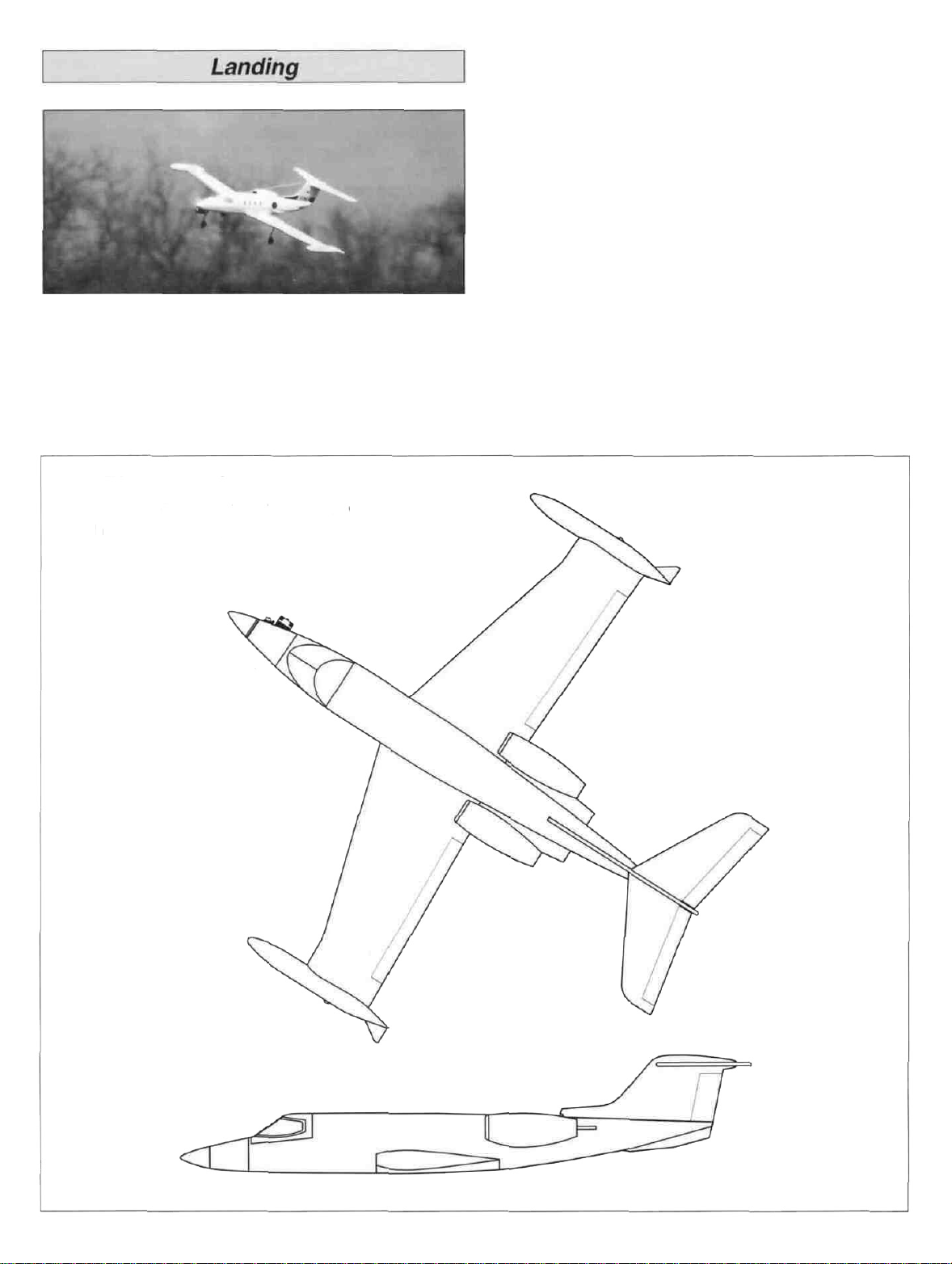
model a few inches above the runway. Plan to land slightly
faster than stall speed on the main wheels first, as this is the
smoothest way to land your Learjet.
In the event of a "dead stick" landing where you may not
make it to the runway, leave the gear retracted (if so
equipped) until the last possible moment to help stretch your
glide. If you definitely won't make the runway, and no other
smooth surface is within range, leave the gear retracted and
make a belly landing on the softest surface you can find. It's
easier to patch scuffed MonoKote than having to repair
damaged landing gear mounts and retract mechanisms.
Landing is straightforward with no tricky tendencies. Just cut
the power to a reliable idle, raise the nose slightly, and the
Learjet will naturally bleed off airspeed. Once the Learjet has
slowed down, lower the landing gear (if using retracts), then
control your descent with power. Upon the final approach, if
you find that you must add power, do so gradually. Just
before touchdown, gradually feed in up elevator to flare the
2-VIEW DRAWING
Photocopy or trace this two-view drawing
and use the copy to plan your trim scheme.
Have a ball! But always stay in control and fly in a
safe manner.
GOOD LUCK AND GREAT FLYING!
SEE THE FULL LINE OF GREAT PLANES AIRPLANE
KITS AND ACCESSORIES AT YOUR HOBBY DEALER.
 Loading...