

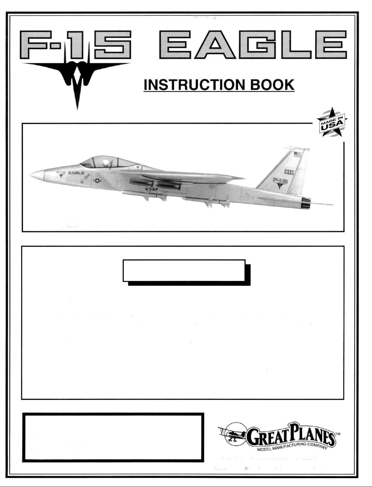
Page 1
(Armament package sold separately)
WARRANTY
Great Planes Model Manufacturing Co., Inc. guarantees this kit to be free from defects in both
material and workmanship at the date of purchase. This warranty does not cover any component parts
damaged by use or modification. In no case shall Great Planes' liability exceed the original cost of the
purchased kit. Further, Great Planes reserves the right to change or modify this warranty without notice.
In that Great Planes has no control over the final assembly or material used for final assembly, no
liability shall be assumed nor accepted for any damage resulting from the use by the user of the final userassembled product. By the act of using the user-assembled product the user accepts all resulting
liability.
If the buyer is not prepared to accept the liability associated with the use of this product, he
is advised to immediately return this kit in new and unused condition to the place of purchase for a
full refund.
READ THROUGH THIS INSTRUCTION BOOK FIRST.
IT CONTAINS IMPORTANT INSTRUCTIONS AND
WARNINGS CONCERNING THE ASSEMBLY AND
USE OF THIS MODEL.
P.O BOX 788 URBANA ILLINOIS 61801 217398-8970
Entire Contents c 1993, Hobbico, Inc F154P03 V1.0
Page 2
LAST MINUTE ADDITIONS
Staple this inside your book
1. In step 5 on page 24 and in step 3 on page
40, we have provided a slightly different style of
nylon torque rod horn than shown. You will need to
drill these horns with a 7/64" drill and tap them
using the 6-32 thread-cutting screw provided.
F154ADD1
Page 3
TABLE OF CONTENTS
INTRODUCTION............................................. 3
PRECAUTIONS........................................... 3
OTHER ITEMS REQUIRED ........................ 4
SUPPLIES AND TOOLS NEEDED.............. 4
DECISIONS YOU MUST MAKE NOW........ 5
COMMON ABBREVIATIONS
TYPES OF WOOD
GET READY TO BUILD............................... 5
DIE-CUT
TAIL FEATHERS
BUILD THE FIN AND RUDDER................... 7
BUILD
TEMPORARILY INSTALL HINGES AND
TORQUE RODS........................................... 9
FUSELAGE ASSEMBLY................................ 10
PREPARE FUSE SIDES............................. 10
MOUNT ENGINE AND INSTALL SERVOS....... 18
BUILD THE NOSE SECTION ..................... 22
INSTALL THE RECEIVER BATTERY..........23
GLUE THE STABS ON
MAKE ELEVATOR PUSHROD.................... 25
FINISH UP THE FUSELAGE...................... 26
PARTS
THE STAB. AND
......................................
DRAWING
............................................
.....................
.......................
ELEVATOR
...............................
...........
5
5
6
7
8
24
DECALS AND TRIM.................................... 46
WING SEATING.......................................... 47
RE-INSTALL ENGINE & RADIO ................. 47
CONTROL SURFACE THROWS................ 47
BALANCE YOUR MODEL .......................... 47
FINAL HOOKUPS AND CHECKS............... 48
PRE-FLIGHT.................................................. 49
CHARGE THE BATTERIES........................ 49
FIND A SAFE PLACE TO FLY.................... 49
GROUND CHECK THE MODEL................. 49
RANGE CHECK YOUR RADIO .................. 49
ENGINE SAFETY PRECAUTIONS............. 49
AMA SAFETY CODE .................................. 50
FLYING........................................................... 50
TAKEOFF.................................................... 50
FLYING........................................................ 50
LANDING .................................................... 51
2-VIEW DRAWING......................................... 52
METRIC CONVERSIONS
WING.............................................................. 28
SPARS
BUILD THE WING PANELS........................ 29
INSTALL WING TOP SHEETING................ 33
INSTALL THE BOTTOM WING SHEETING...... 35
INSTALL THE AILERON TORQUE RODS........ 38
ASSEMBLE AILERONS.............................. 39
INSTALL AILERON SERVO........................ 40
FINISHING THE WING ............................... 41
FINAL ASSEMBLY......................................... 42
MAKE RUDDER PUSHRODS
FIT THE WING TO THE FUSE ................... 42
PREPARE THE CANOPY........................... 43
BALANCE THE AIRPLANE LATERALLY.... 44
FINAL SANDING......................................... 44
COVERING................................................. 44
GLUE FINS IN PLACE................................ 44
GLUE THE AILERON HINGES................... 44
GLUE TAIL FEATHER HINGES ..................45
COCKPIT & SEAT....................................... 45
GLUE CANOPY IN PLACE......................... 46
........................................................
....................
28
42
1"= 25.4 mm (conversion factor)
1/64" =
1/32" =
1/16" =1.6
3/32" =
5/32" = 4
3/16" =4.8
3/8" =
5/8"
3/4" =19
.4 mm
.8 mm
mm
2.4 mm
1/8" = 3.2 mm
mm
mm
1/4"
=6.4
mm
9.5 mm
1/2" =12.7
=15.9
1" =25.4 mm
2" = 50.8 mm
3" = 76.2 mm
6" = 152.4mm
12" =304.8 mm
15"
=381
18" =457.2 mm
21" =533.4 mm
24" = 609.6 mm
30" = 762 mm
36" =914.4 mm
mm
mm
mm
mm
2
Page 4
WARNING! THIS IS NOT A TOY! THIS IS NOT A
BEGINNER'S AIRPLANE!
This R/C kit and the model you will build is not a toy! It is capable of serious bodily harm
and property damage IT IS YOUR RESPONSIBILITY AND YOURS ALONE, to build this kit correctly,
properly install all R/C components and flying gear (engine, tank, pushrods, etc) and to test the model
and fly it only with experienced, competent help, using common sense and in accordance with all safety
standards as set down in the Academy of Model Aeronautics Safety Code It is suggested that you join
the AMA and become properly insured before you attempt to fly this model IF YOU ARE JUST
STARTING R/C MODELING, CONSULT YOUR LOCAL HOBBY SHOP OR WRITE TO THE ACADEMY
OF MODEL AERONAUTICS TO FIND AN EXPERIENCED INSTRUCTOR IN YOUR AREA.
Academy of Model Aeronautics
1810 Samuel Morse Dr
Reston, VA 22090 (703)435-0750
address and phone
expires June 30, 1993
Academy of Model Aeronautics
5151 E Memorial Drive
Muncie, IN 47302 (317)289-4236
Change of Address and phone
active July 1, 1993
INTRODUCTION
Congratulations and thank you for
purchasing the Great Planes F-15 EAGLE!
The Great Planes F-15 is a high
performance propeller-driven sport airplane that
resembles the real F-15 Eagle In the air, the prop
is invisible, adding to the realism The smoothness
and speed of this airplane allow you to experience
the thrills of flying a Jet-like airplane without the
complexity and high cost of a ducted fan model.
And yet, the F-15 is very stable and forgiving,
allowing even less-experienced pilots to enjoy it
This is not a beginner's airplane! While the
F-15 Eagle is not hard to build and flies great, we
must discourage you from selecting this kit as your
first R/C airplane It is very fast, highly
maneuverable, and lacks the self-recovery
characteristics of a good basic trainer such as the
Great Planes PT Series airplanes On the other
hand, if you are confident with your flying skill and
can safely handle aileron airplanes such as the
Great Planes Big Stik Series airplanes, the F-15
is an excellent choice
Please inspect all parts carefully
before starting to build! If any parts are
missing, broken or defective, or if you
have any questions about building or
flying this airplane, please call us at
(217) 398-8970 and we'll be glad to help. If
you are calling for replacement parts,
please look up the part numbers and the
kit identification number (stamped on the
end of the carton) and have them ready
when calling.
PRECAUTIONS
1 You must build the plane according to the
plans and instructions. Do not alter or modify
the model, as doing so may result in an unsafe or
unflyable model In a few cases the plans and
instructions may differ slightly from the photos In
those instances you should assume the plans and
written instructions are correct Also, you may
notice a slight difference in length between longer
parts and the plans This is normal and is caused
by the plans expanding and shrinking with the
changing moisture content in the air Do not
modify the parts to fit the plan.
2. You must take time to build straight, true
and strong IMPORTANT - Glue should never be
substituted for a good-fitting joint Take a little
extra time to get a good fitting joint and glue it
properly and it will be stronger, neater, and much
lighter than a bad joint held together with a glob of
glue!
3
Page 5
3. You must use a proper R/C radio that is in
first class condition and meets the current AMA
and FCC requirements and the requirements of
your local flying club, the correct sized engine and
correct components (fuel tank, wheels, etc.).
4. You must properly install all R/C and other
components so that the model operates properly
on the ground and in the air
5. You must test the operation of the model
before the first and each successive flight to insure
that all equipment is operating, and you must make
certain that the model has remained structurally
sound.
6 You must fly the model only with the
competent help of a well experienced R/C pilot if
you are not already an experienced and
knowledgeable R/C pilot at this time.
Note: We, as the kit manufacturer, can
provide you with a top quality kit and
great instructions, but ultimately the
quality and flyability of your finished
model depends on how you build it;
therefore, we cannot in any way
guarantee the performance of your
completed model, and no
representations are expressed or
implied as to the performance or safety
of your completed model.
Remember: Take your time and follow
directions to end up with a well-built model that
is straight and true.
OTHER ITEMS REQUIRED
D Four-channel radio with 4 servos
D Propellers (see engine instructions for
recommended sizes)
D 2-1/4" Spinner (Hobbico® 2-1/4" Jet spinner
(HCAQ3750) recommended)
D 2-3/4" Main Wheels (Great Planes GPMQ4204
recommended) See page 5
D 2-1/4" Nose Wheel (Great Planes GPMQ4202
recommended) See page 5
D 10oz Fuel Tank (Great Planes GPMQ4104
recommended)
D 5/32" Wheel Collars - (6 needed) (2 packages
of GPMQ4306)
D Iron-on Covering Material (2 rolls) (Top Flite®
Aluminum Super MonoKote® recommended)
D Fuelproof Paint for trim We used Chevron
"Perfect Paint" silver on the turtle deck
D Semi-flexible Pushrods (2-sets) (GPMQ3714)
D Silicone Fuel Tubing (GPMQ1234)
D 1/16" thick Wing Seating Tape (GPMQ4422))
D 1/4" thick Latex Foam Rubber Padding
D Plastic Pilot. Williams Bros Military 1-1/2"
Scale #171
D Quick-Connectors - (3 needed) (2 packages of
GPMQ3870)
SUPPLIES AND TOOLS NEEDED
D 2 oz Thin CA Adhesive (Top Flite Supreme)
D 2 oz Medium or Thick CA Adhesive (Supreme)
D 30-Minute Epoxy (Bullet)
D Hand or Electric Drill
D Drill Bits 1/16", 5/64", 7/64", 1/8", 5/32", 3/16",
13/64", 1/4" and 5/16"
D Sealing Iron (Hobbico or Top Flite recommended)
D Heat Gun (Hobbico or Top Flite recommended)
D Hobby Saw (Razor Saw)
D Hobby Knife, #11 Blades
D Screw Drivers
D T-Pins
D Straightedge
D Strapping Tape (Required for construction)
D Sandpaper (coarse, medium, fine grit) *
D T-Bar Sanding Block (or similar)
D Waxed Paper
D Lightweight Balsa Filler (Hobbico Hobbylite™)
D Vaseline Petroleum Jelly
D IsopropyI Rubbing Alcohol (70%)
D 3M "77" Spray Adhesive (optional)
D Dremel Moto Tool or similar (optional)
*NOTE: On our workbench, we have four 11"
T-Bar sanders, equipped with #50, #80, #100
and #150-grit sandpaper. We also keep
some #320-grit sandpaper handy for finish
sanding, before covering.
4
Page 6
DECISIONS YOU MUST MAKE NOW
ENGINE, MOUNT AND MUFFLER
SELECTION
The recommended engine for the F-15
is a .40* - .50 cubic inch displacement 2-cycle
*NOTE Performance may be marginal if a nonschneurle-ported 40 cu in 2-Cycle engine is
used The engine you select will determine how
you build the fuselage nose section, so it is
important that you have the engine close at
hand while building Because of the size
limitations and the nature of this model, 4-cycle
engines are more difficult to install and balance
and therefore are not recommended.
This kit includes a Great Planes
EM4070 adjustable engine mount (or similar
mount) that will fit most .40 - .61 (2-Cycle)
engines If the supplied mount does not fit your
engine, it may be necessary to purchase a
different mount (check with your hobby dealer).
SELECTION OF WHEELS
To save weight, we recommend using Great
Planes Ultralight wheels REMEMBER: Large
wheels are ugly and unrealistic on a model of
this type, so try to keep the wheels as small as
possible
If you will be flying from a concrete or
asphalt runway, we recommend 2-1/4" main
wheels and a 2" nose wheel.
For grass fields, larger wheels will be
required, such as 2-3/4" main wheels and a
2-1/4" to 2-1/2" nose wheel
COMMON ABBREVIATIONS
USED IN THIS BOOK AND
ON THE PLANS:
Elev = Elevator
Fuse = Fuselage
LE = Leading Edge (front)
LG = Landing Gear
Ply = Plywood
Stab = Stabilizer
TE = Trailing Edge (rear)
Tri = Triangle
" = Inches
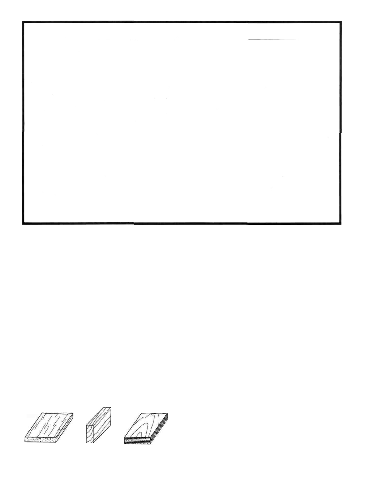
TYPES OF WOOD
GET READY TO BUILD
THE
F-15
D 1. Unroll the plan sheets and re-roll them
inside out to help them lie flat.
D 2 Remove all parts from the box As you do,
figure out the name of each part by comparing it
with the plans and the parts list at the back of this
book Using a felt tip pen, write the part name or
size on each piece to avoid confusion later Use
the die-cut part patterns shown on page 6 to
identify the die-cut parts but do not punch them out
until you are ready to use them Save all scraps.
If any of the die-cut parts are difficult to punch out,
do not force them' Instead, first cut around the
parts with a hobby knife After punching out the
die-cut parts, use your T-Bar or sanding block to
lightly sand the edges to remove any die-cutting
irregularities.
Balsa Basswood Plywood
D 3 As you identify and mark the parts,
separate them into groups, such as fuse
(fuselage), wing, fin and stab (stabilizer), and
hardware.
5
Page 7
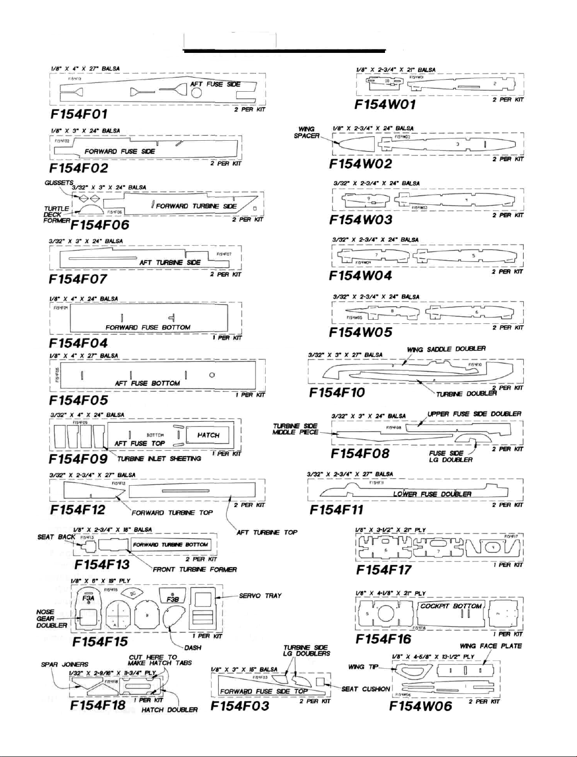
DIE-CUT PATTERNS
6
Page 8
TAIL FEATHERS
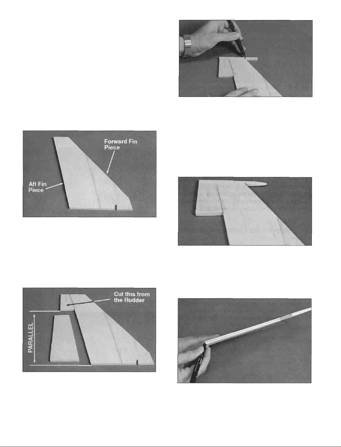
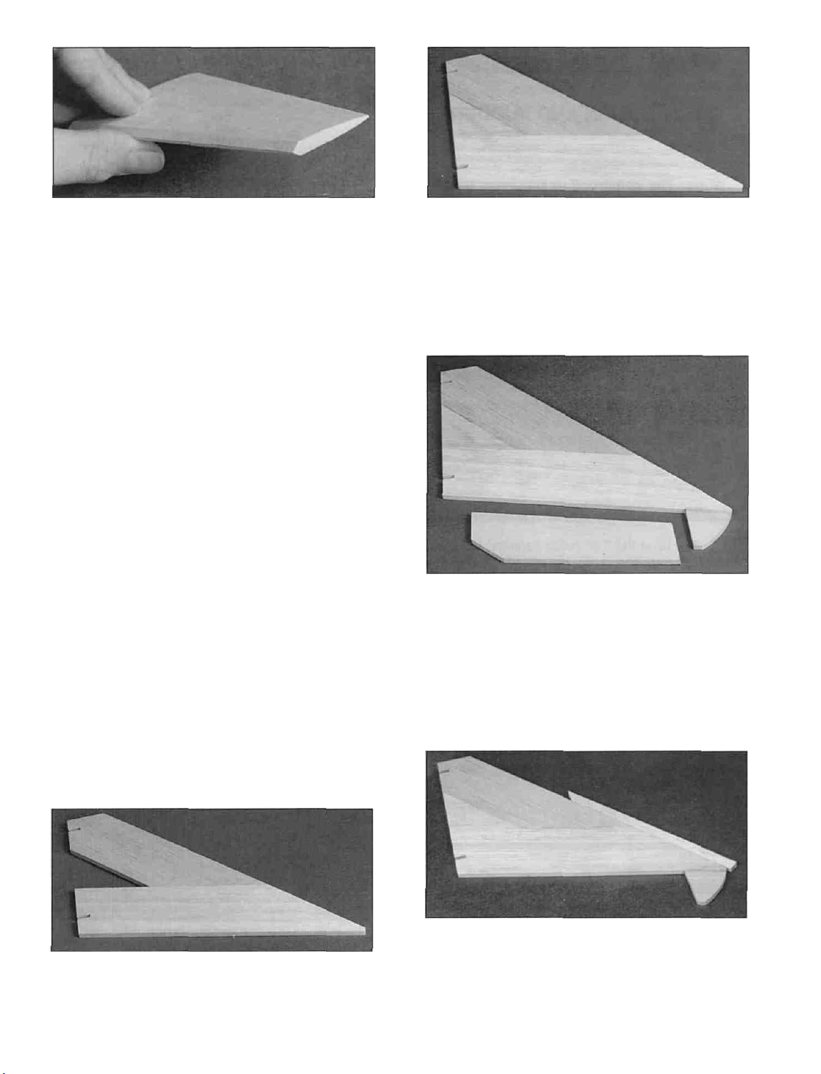
BUILD THE FIN AND RUDDER
Note: The construction sequence that
follows does not require building over
the
plans.
occasionally need to refer to the plans.
You
will
however,
D D 3. Cut the 1/4" sq. x 7-7/8" basswood
stick (F154R04) in half to make two fin tips
approximately 3-7/8" long . Hold a fin tip in place
on top of the fin so the aft end just overlaps the fin
TE. Mark on the fin tip where the fin LE starts.
Remove the fin tip. Carve and sand the front of
the fin tip to a round cross section but do not sand
behind the line you just made.
D D 1. Glue the 1/4" balsa forward fin piece
(F154R01) to the 1/4" balsa aft fin piece
(F154R02) so their bottoms are even with each
other.
D D 2. Using the plans as a guide, cut the top
2-1/2" off a 1/4" balsa rudder (F154R03) with a
razor saw. Glue the top portion to the aft fin piece
as shown above. The bottom edge of the top
portion should be parallel with the bottom edge of
the
fin.
D D 4. Glue the fin tip to the top of the fin.
Sand the aft edge of the tip flush with the fin TE.
D D 5. Use a sanding block with medium
(150) grit sandpaper to sand the edges and both
sides of the fin smooth. Carefully draw a
centerline all around the edges of the fin and
rudder. This will make it easier to maintain
symmetry when sanding later.
7
Page 9
D D 6. Using a sanding block and coarse (50
or 80-grit) sandpaper, sand both sides of the
rudder to a taper (see cross-section on plans).
The trailing edge should end up approximately
3/32" wide. (Do not sand to a sharp edge). Leave
the top and bottom edges square. Sand the
leading edge of the rudder to a "V-shape" as
shown on the plan. HINT: It is a good idea to keep
new, sharp sandpaper on your sanding blocks.
You will notice that it "cuts" the wood and the glue
cleaner and produces a much smoother finish.
D D 7. Sand the leading edge of the fin to a
rounded shape (see cross-section on plans). Sand
the trailing edge of the fin (above the rudder) to
the same taper as the rudder. Do not sand the TE
of the fin where the rudder will be attached.
D 8. Go back to step 1 and build another fin and
rudder.
BUILD THE STABILIZER AND
ELEVATORS
D D 2. Test fit the 1/4" balsa middle stab
piece (F154S02) in place. Sand it if necessary to
achieve a good fit and glue it in place. Sand the
root of the stab until all three pieces are even with
each other.
D D 3. Position the 1/4" balsa elevator
(F154S04) over the plan and mark where the stab
tip will be cut off. Cut the tip off with a razor saw
and glue it to the stab rear. Do this over the plans
so you will be sure to position it correctly.
Note: The construction sequence that
follows does not require building over
the
plans.
occasionally need to refer to the plans.
D D 1. Glue the 1/4" balsa forward stab
piece (F154S01) to the 1/4" balsa aft stab piece
(F154S03) so the root ends are even with each
other.
You
will
however,
D D 4. Position the 1/4" x 1/2" x 18" balsa
stick (F154S05) over the plans and cut it in half at
an angle to make the stab leading edge
extensions. Glue an extension to the leading
edge of the stab, and sand it to match the contour
of the stab as shown on the plans.
8
Page 10
D D 5. Use a sanding block with medium
(150) grit sandpaper to sand the edges and both
sides of the stab smooth. Carefully draw a
centerline all around the edges of the stab and
elevator. This will make it easier to maintain
symmetry when sanding later.
A. Begin by carefully cutting a very shallow
slit at the hinge location. The first cut is to
establish your cut in the right place, so
concentrate on staying on the line and
don't cut too deep.
D 6. Sand the tip and leading edges of the stab
to a rounded shape (see cross-section on plans).
D 7. Now go back and build the other side.
TEMPORARILY INSTALL HINGES
AND TORQUE RODS
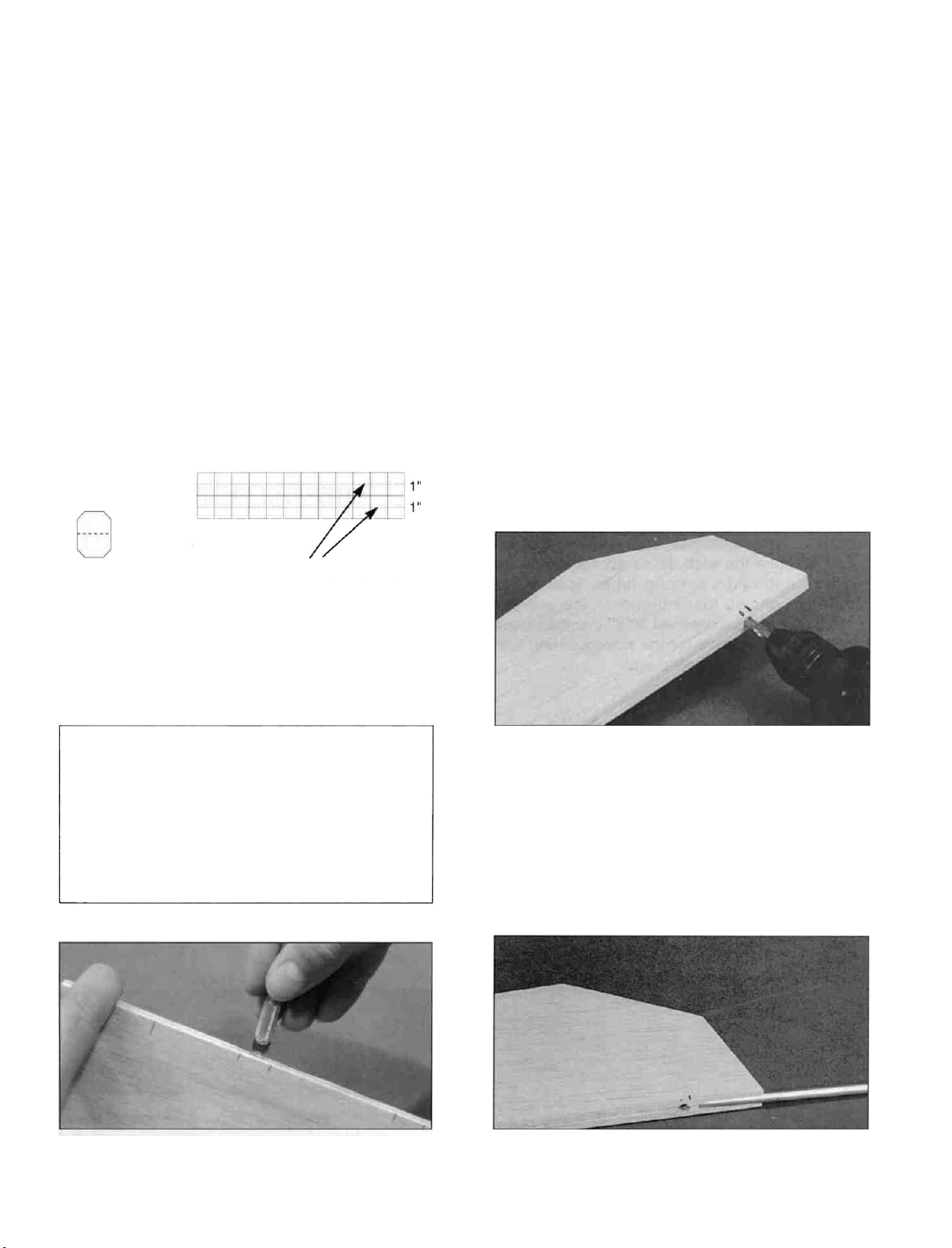
D 1. Cut 24 hinges 3/4" x 1" from the 2" x 9" CA
hinge strip.
(NYLON87).
Clip off the corners
of each hinge.
Hinge Center Line
D 2. Using the plans as a guide, mark the hinge
locations on the stabs, elevators, fins and rudders.
Also designate one of each as being "right" and
the others as "left".
3/4-
B. Make three or four more cuts in the same
line, going slightly deeper each time. As
you make these additional cuts, work on
going straight into the wood. Continue this
process while "wiggling" the knife handle
forward and backward until the blade has
reached the proper depth for the hinge.
C. Trial fit the hinge into the slot. If the hinge
is difficult to push in, re-insert the knife and
move it back and forth in the slot a few
times to enlarge the slot. Do not glue the
hinges yet.
CAUTION!!!: You must use extreme care
when cutting hinge slots with a hobby knife,
to avoid cutting yourself! If the balsa part
breaks while you are pushing on the knife,
the blade could go into your hand before
you know it! A good precaution is to wear
leather gloves while performing the
following steps.
D 2. Cut the hinge slots on the centerlines you
drew earlier. Our recommended hinge slotting
method is described in the next column.
D 4. Using the plans for reference, mark the
location of the torque rods on the elevators. Drill
a 1/8" hole 1-1/8" deep into each elevator as
shown in the photo.
D 5. Groove the elevator leading edge to accept
the torque rod wire. HINT: Use a hobby knife to
9
Page 11
sharpen the inside of one end of a 1/8" diameter
brass tube, and use it to cut this groove.
and 2" long, from the border of a die-cut 1/8" sheet.
Glue this piece to the inside of the stab tip. Sand it
to the contour of the stab as shown in the photo.
D 9. Trial fit all these parts together using the
torque rods and hinges. Check the operation of
the elevators, but do not glue anything yet.
FUSELAGE
ASSEMBLY
PREPARE FUSE SIDES
D 6. Groove the stab TE to accept the torque
rod wire and nylon bearing tube. Ideally, the
torque rod should be centered on the elevator
hinge line. Use a sharpened 3/16" diameter brass
tube to cut the groove for the nylon bearing tube
and a 1/8" brass tube for the wire.
D 7. Using a sanding block and coarse (50 or
80-grit) sandpaper, sand both sides of each
elevator to a taper (see cross-section on plans).
The trailing edge should end up approximately
3/32" wide (Do not sand to a sharp edge). Leave
the ends square. Sand the leading edge of the
elevator to a "V-shape" as shown on the plan.
Sand the trailing edge of the stab tip to the same
taper as the elevator.
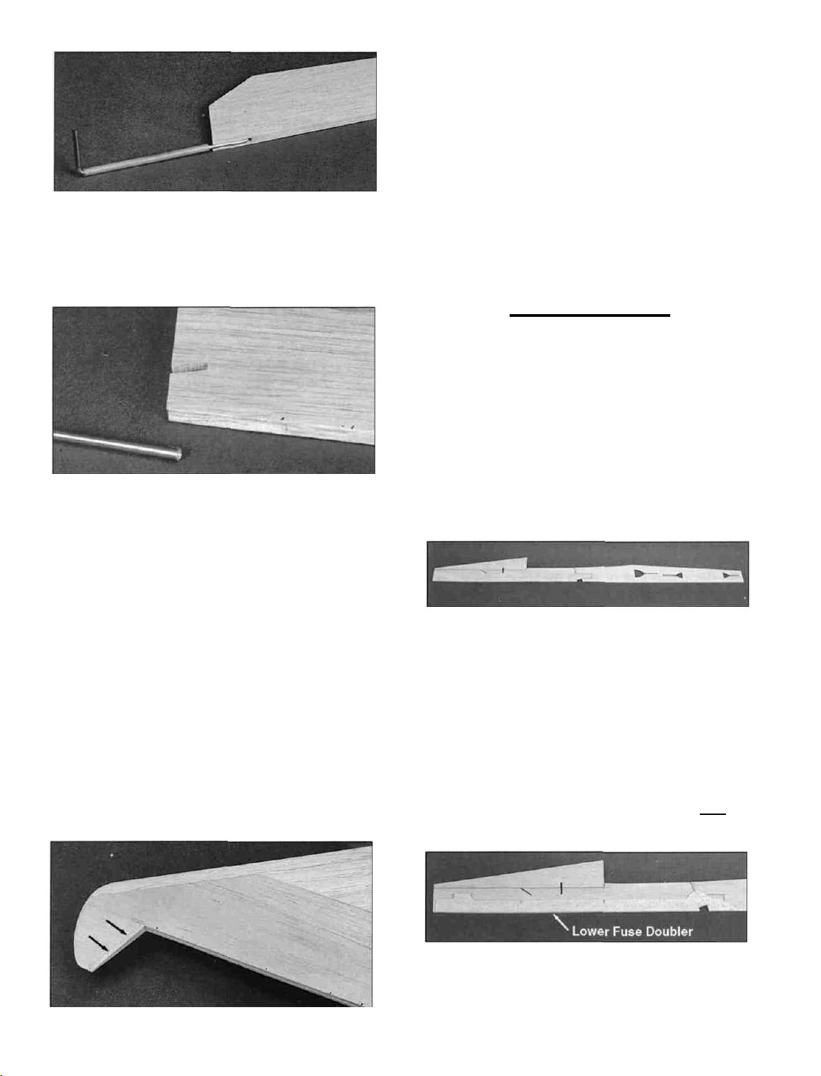
D D 1. Working over the fuselage side view
covered with waxed paper, trial fit a die-cut 1/8"
balsa forward fuse side (F154F02), forward
fuse side top (F154F03) and aft fuse side
(F154F01) together, sanding as necessary for a
good fit. Use a straight edge along the bottoms to
keep them aligned and glue them together.
NOTE: If this is your second time
through, remember to make a right and
a left side.
D D 8. Cut a piece of 1/8" balsa, 1/4" wide
D D 2. Position a die-cut 3/32" balsa lower
fuse doubler (F154F11) by lining it up with the
landing gear block cut-out and the bottom of the
fuse side. Apply thin CA all around the doubler to
glue it in place.
10
Page 12
D D 3. Position a die-cut 3/32" balsa upper
fuse side doubler (F154F08) near the top of the
fuse side so it fits against the lower fuse doubler.
Note that the aft portion of this doubler is recessed
1/8" below the top of the fuse side to allow for the
cockpit bottom. Glue the doubler to the fuse side
by applying thin CA around all edges of the
doubler.
NOTE: The doublers stop 1/4"
before the front of the fuse side to
align the firewall.
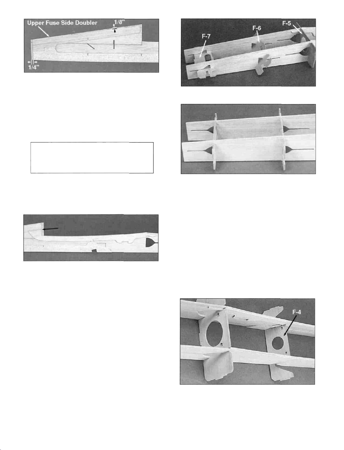
D 6. Drill a 3/16" hole at each of the two punch
marks on the die-cut 1/8" ply former F5 (F154F16).
Slide formers F5, F6 and F7 (F154F17) into their
respective slots and carefully twist them into place.
The photo shows the sequence used to
accomplish this. Slide the former into the slots,
and rotate them 90 degrees until they are
positioned as shown in the photo above. Do not
glue them yet. Make sure they are upright and
not inverted!
D D 4. Position a die-cut 3/32" balsa wing
saddle doubler (F154F10) as shown in the photo.
Notice that the aft edge of the front portion is
aligned with the aft edge of the fuse doubler top.
The top surface of the doubler should be flush with
the edge of the fuse side.
D 5. Go back to step 1 and build another
fuselage side. Be sure to make a right and a left
side!
NOTE - in the following steps, the
fuselage
will
be
assembled
without
being securely glued together. This
technique allows all of the self aligning
parts to be installed before the fuselage
is locked together with glue.
D 7. Drill a 3/16" hole at each of the two punch
marks on the die-cut 1/8" ply former F4 (F154F17).
Install F4 by sliding it up from the bottom of the
fuse. Tack glue it in place against the aft edge of
the landing gear block slot.
11
Page 13
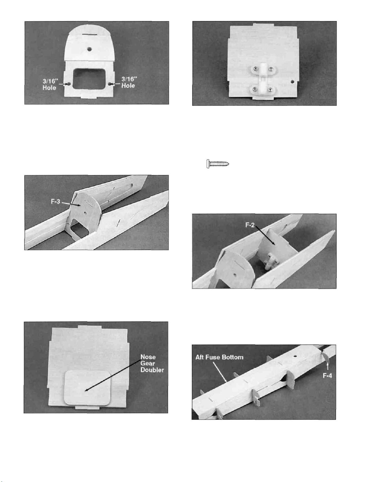
D 8. Securely glue die-cut 1/8" ply former F3B
to former F3A (F154F15). Align it with the hole
and the tabs in F3A as shown in the photo. Notice
that the nose gear doubler is the lightening
hole from F3. Save this piece. Drill 3/16" holes
at the two punch marks on F3A.
D 9. Tack glue F3 in place in the fuselage with
F3B towards the nose of the plane. Only apply a
couple drops of thin CA on the bottom half of F3.
You will glue the top portion of the former later.
D 11. Flip former F2 over and drill a 5/64" hole at
each of the four nose gear bearing punch marks.
Also drill a 3/16" hole at the remaining punch mark
for the throttle pushrod. Attach the nylon nose
gear bearing (NYLON33) using four
#4 x 1/2" screws fSCRW004^.
Apply a drop of thin CA to the
back side of each #4 screw to
keep them from vibrating loose.
D 10. Glue the die-cut 1/8" ply nose gear
doubler (from former F3A) to former F2
(F154F16). Locate it on the side opposite the
nose gear bearing punch marks and just above the
bottom of the former (not the tab) as shown.
D 12. Tack glue F2 into the fuse with a few drops
of thin CA. The nose gear bearing should be
towards the rear of the fuselage.
D 13. Lay the die-cut 1/8" balsa aft fuse bottom
(F154F05) in place and allow the formers to key
into the notches in the bottom. Center the aft fuse
bottom on former F4 and tack glue it in place with
thin CA.
12
Page 14
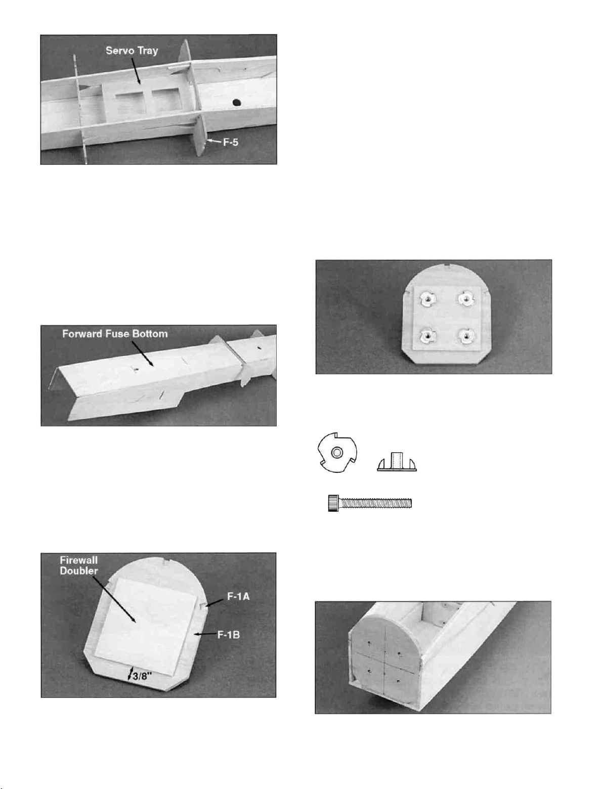
D 14. Slide the die-cut 1/8" ply servo tray
(F154F15) down into the slot through which F5
was inserted. It is a tight fit, but insert one tab into
the slot and then twist the other tab into place.
Slide the tray up against F-5 and glue it in place.
Now that the aft half of the fuselage is held
straight, add glue to F4, F5, F6, F7 and the aft fuse
bottom to securely hold everything together. We
recommend applying thin CA to all joints, followed
by medium CA.
sure they are accurately lined up with one another
and the side of F1A with the punch marks is
showing. Wipe off any excess glue before it
cures. Glue the 1/8" x 2-3/8" x 2-3/8" plywood
firewall doubler (F154F30) to F1B. It should be
positioned approximately 3/8" above the bottom of
the firewall and centered side to side.
D 17. If you are using the supplied Great Planes
Adjustable Engine Mount (EM4070), drill a 5/32"
hole at each of the four punch marks on the face of
the firewall. If you are using another mount, center
it on the embossed center lines to determine
where to drill the holes.
D 15. Lay the die-cut 1/8" balsa forward fuse
bottom (F154F04) in place and allow formers F2
and F3 to key into it. Center the forward fuse
bottom at the LG block and tack glue the fuse
bottom to the fuse sides between F-2 and the LG
block. Do not glue forward of F-2 at this time.
D 18. Lay the firewall down with F1A against the
work surface. Use a hammer to gently tap a 6-32
blind nut (NUTS003)mto each 5/32" hole.
Temporarily attach the
engine mount to the
firewall with the 6-32 x 1"
socket head bolts
(SCRW078) to make sure
the holes are in the
correct position. Adjust
the holes if necessary
and then add a bead of thick CA or epoxy around
each blind nut to hold them in place. Do not allow
the glue to get on the threads.
D 16. Locate the die-cut 1/8" ply F-1A and F1B
(F154F15) and use a fine sanding block to remove
any fuzzy edges. Use epoxy to glue the two
pieces together making a 1/4" thick firewall. Make
D 19. Use epoxy to securely glue the firewall into
place making sure it is centered on the forward
13
Page 15
fuse bottom. The firewall should be positioned
against the fuse doublers to properly set the
engine down thrust. Apply thin CA along the fuse
side/forward fuse bottom joint.
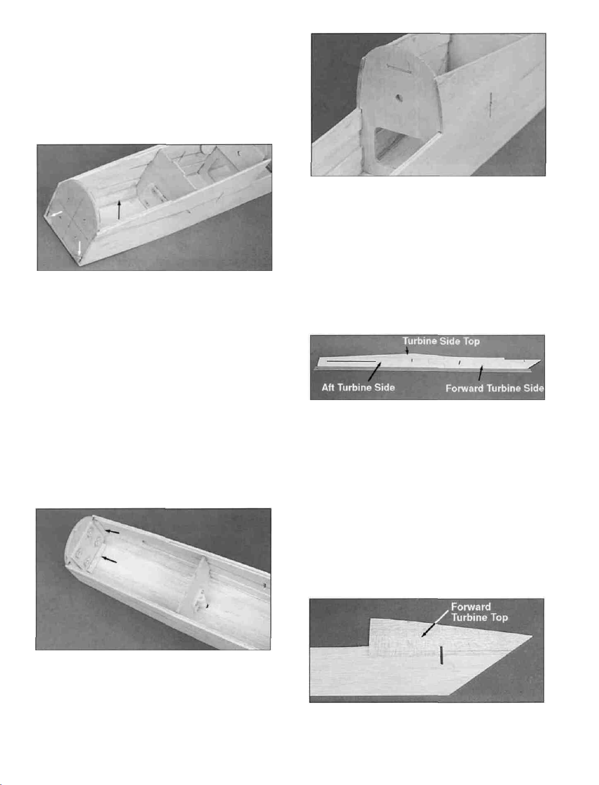
D 20. Slide the 1/2" x 30" balsa triangle stock
(WSTR014) through one of the triangular holes at
the bottom of the firewall until it touches former F2.
Cut the 1/2" triangle off flush with the front of the
firewall. Press the triangle into the corner formed
by the fuse side and the fuse bottom and apply
thin CA along the edges of the triangle. Install
another piece of 1/2" balsa triangle on the other
side of the fuselage. Sand the fuse sides, fuse
bottom and the triangle flush with the front of the
firewall.
D 22. Pull the fuse sides up tight against the top
portion of former F3 and securely glue them in
place. Strapping tape can be used to hold the fuse
sides in place while the glue cures. Add glue to all
the front fuse joints to securely glue everything
together.
D 23. Trial fit the die-cut 3/32" balsa forward
turbine side (F154F06), the aft turbine side
(F154F07) and the turbine side top(F154F08)
together on a flat surface covered with waxed
paper. Sand them if necessary to get them to fit
together nicely. Use a straight edge along the
bottom edges to keep them aligned and glue them
together with thin CA. Note: Do not lose the
die-cut gussets that are in F154F06.
D 21. Cut three 1-7/8" long pieces of 1/4" balsa
triangle from the 1/4" x 30" balsa triangle stock
(WSTR015) . Glue one of the pieces into the
corner formed by the firewall and the fuse bottom.
Glue the other two pieces into the corners formed
by the firewall and the fuse sides. Note: you may
need to trim the triangle to get it to fit.
D 24. Glue the die-cut 3/32" balsa forward
turbine top (F154F12) in place. Assemble the
other turbine side.
14
Page 16
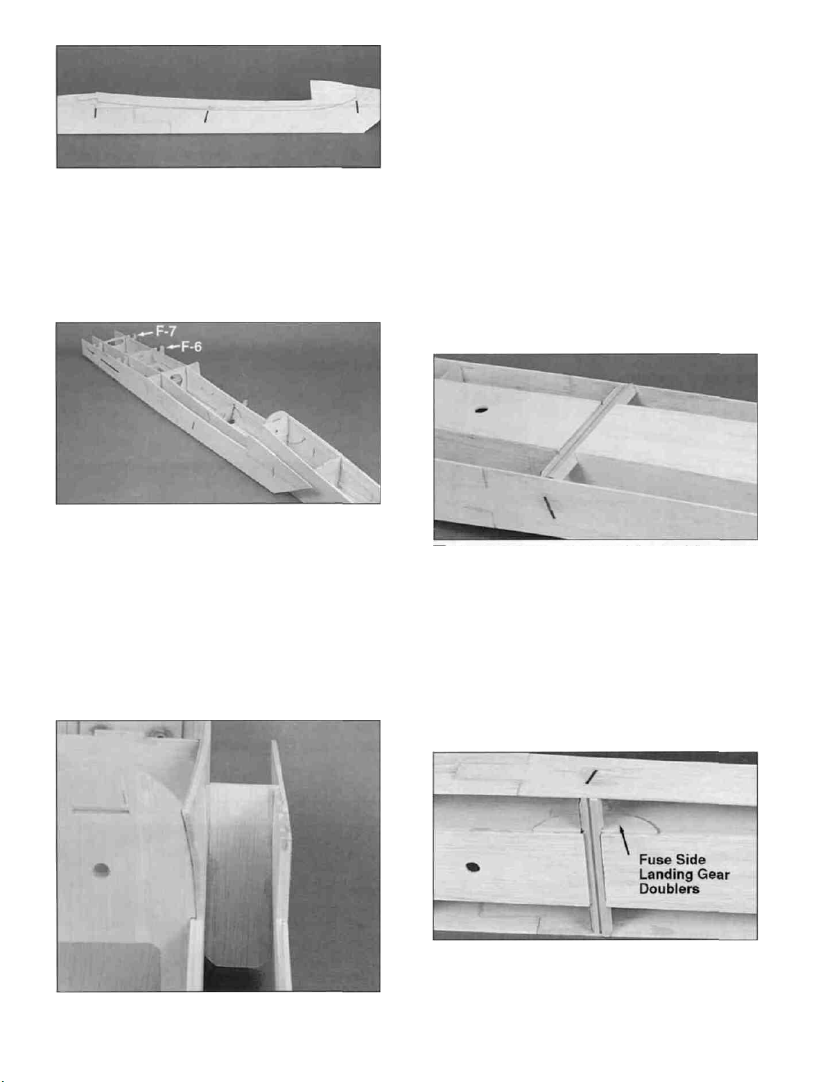
D 25. Glue a die-cut 3/32" balsa turbine doubler
(F154F10) to each turbine side. They should be
aligned with the wing saddles. Be sure to make a
right and a left turbine side!
as shown in the photo. Make sure the bottom of
the former is flush with the bottom of both the fuse
side and the turbine side.
D 28. Install the other turbine side and front
turbine former using the same technique described
above.
D 26. Glue a turbine side onto formers F4 and
F5. Pull the turbine side up against former F7 and
make sure the bottom of the turbine side is level
with the bottom of the former. Glue it to the former.
Do the same for former F6 and then go back and
add thick CA to each joint.
D 29. Test fit the 7/16" x 5/8" x 6-5/8" grooved
basswood landing gear block (F154F21) into its
slot in the bottom of the fuselage. Trim the slot or
sand the ends of the block if necessary to get the
landing gear block to fit. Securely glue it in place.
D 27. Snap the die-cut 1/8" balsa front turbine
former (F154F13) into its slots and glue it in place
D 30. Glue the die-cut 3/32" balsa fuselage side
landing gear doublers (F154F08) to the outside
of each fuse side as shown in the photo.
15
Page 17

D 31. Glue the four die-cut 1/8" balsa turbine
side landing gear doublers (F154F03) to the
inside of each turbine side as shown in the photo.
D 32. Securely glue (using epoxy) the two 7/16" x
5/8" x 1-1/4" grooved basswood short landing
gear blocks (F154F22) in place against the
fuselage side doubler. The grooved side of the
blocks should be against the fuse doubler.
D 34. Cut eight 7-1/2" long fin and stab braces
from the two 1/8" x 1/2" x 30" balsa sticks
(F154F29). Glue these in place as shown on the
plans and in the photo. They should be securely
attached to formers F6 and F7. The stab braces
should also be attached to the turbine sides. The
top of the fin braces should be flush with the top of
the formers.
D 35. Cut two 15-3/4" long pieces of 1/4" x 30"
balsa triangle (WSTR015). Glue these inside the
top edge of each turbine side from F5 rearward.
Make sure the top edge of the triangle is flush with
the top edge of the turbine side.
D 33. Drill two 5/32" holes through the long
landing gear block by using the grooves in the
short blocks as guides. Cut two 1-1/2" long pieces
of 1/4" balsa triangle. Glue them to the front of
each short L.G. Block. These are not shown in the
photos, but are illustrated on the fuselage plan.
D 36. Flip the fuselage over and install 1/4" balsa
16
Page 18

triangle along the bottom edge of the turbines. Do
not install triangle over the landing gear doublers.
The triangle should extend all the way from the
front to the aft ends of the turbine sides. Make
sure the bottom edge of the triangle is flush with
the bottom edge of the turbine side.
D 39. Trim and sand the edges of the turbine
bottoms flush with the turbine sides and fronts.
SUGGESTION: From this point on, we
recommend using a padded "cradle"
such as a Robart Super Stand to protect
the fuselage from dents and dings. You
can modify the stand to fit the fuselage
by cutting one upright off flat and
enlarging the other upright to fit the
front of the fuselage. Line the uprights
with foam rubber to protect the plane.
D 37. Glue a 1/8" x 2" x 25" balsa aft turbine
bottom (F154F14) in place. It is butt-glued up
against the LG block and the bottom fuse sheeting,
so hold it flush with the bottom sheeting while you
glue it with thin CA. Add a bead of medium CA
inside the fuselage to reinforce this joint. Glue the
other aft turbine bottom in place.
D 40. Glue two die-cut 3/32" balsa turbine inlet
sheeting pieces (F154F09) together.
D 38. Glue a die-cut 1/8" balsa forward turbine
bottom (F154F13) in place. It is butt-glued up
against the bottom fuse sheeting so hold it flush
with the bottom sheeting while you glue it with thin
CA. Add a bead of medium or thick CA inside the
fuselage to reinforce this joint. Glue the other
forward turbine bottom in place.
D 41. Glue the inlet sheeting in place in its slot
near the front of a turbine. Bend the turbine side in
to meet the inlet sheeting as shown in the photo
and glue it to the sheeting. Assemble the other
turbine inlet sheeting and glue it in place on the
other turbine. Sand the inlet sheeting flush with
the bottom sheeting and the turbine sides.
17
Page 19

(COCKPIT BOTTOM NOT SHOWN)
D 42. Temporarily install the die-cut 1/8" ply
cockpit bottom (F154F16) to hold the fuselage
sides in position. Cut six 1-3/4" long pieces of
turbine forward top sheeting from the 3/32" x 3" x
12" balsa sheet (F154F26). Starting at the front of
the turbine, glue three pieces along the top edge of
each turbine side. Sand them slightly to make
them fit nicely up against the fuselage side. Make
sure the sheeting is installed so it is level (parallel
with the fuse bottom). Sand the edges of the
sheeting flush with the turbine side and the turbine
inlet sheeting. The aft end of the sheeting must be
even with the aft edge of former F-3. Remove the
cockpit bottom.
D 2. Now you may use one of the following
methods to attach your engine to the mount:
Method 1: Screw the #6 x 3/4" sheet metal
screws (SCRW018) through the engine mounting
flange and into the mount. When
first installing these screws, put a
drop of oil into each screw hole.
Method 2: Cut and tap threads into the holes
you just drilled using a 6-32 tap and tap wrench. If
you use this method, you will have to supply your
own 6-32 x 1" socket head cap screws for
attaching the engine to the mount.
MOUNT ENGINE AND
INSTALL SERVOS
D 1. Screw the mount onto the firewall using the
6-32 x 1" cap screws, but leave the screws loose
for now. Place the engine on the mount and
squeeze the mount halves together until they are
within 1/32" of the engine crankcase. Make sure
the mount is centered on the embossed center
lines and tighten the engine mount screws.
Position the engine on the mount so the distance
from the front of the firewall to the face of the thrust
washer is 4-5/16". Mark the engine mounting hole
locations on the mount. Remove the engine and
accurately drill 7/16" (or #36) holes. NOTE: If you
have access to a drill press, use it for drilling these
holes to ensure that they are drilled vertically.
D 3. Install the rudder, elevator and throttle
servos using the screws that came with the servos.
Cut all but one arm off of the throttle and elevator
servo horns and use a long two arm horn for the
rudder servo.
18
Page 20

D 4. Determine where the throttle pushrod
should exit the firewall and drill a 3/16" hole there.
Route the throttle pushrod outer tube from the
firewall to former F5. We used a Great Planes
Semi-Flexible Pushrod (GPMQ3714). Cut the
outer tube to the correct length and remove it from
the plane. Scuff up the outside of the tube with
medium grit sandpaper, replace the tube and glue
it in place.
D 6. Assemble the nylon steering arm
(NYLON16) by inserting a 5/32" wheel collar
(WHCL005) inside the steering arm and securing it
with a 6-32 x 1/4" socket head cap screw
(SCRW007). Slide the 5/32" wire nose gear
(WBNT006) into the bearing, and through the
steering arm. Install a nylon clevis onto the plastic
inner pushrod using the 1" threaded rod that came
with the pushrod. Insert the inner pushrod into the
outer tube and snap the clevis onto the steering
arm. Slide the silicone retainer over the clevis.
Cut a scrap piece of balsa to support the end of
the steering outer tube and glue it in place on the
fuse bottom. Glue the steering outer tube to the
balsa piece but make sure the steering arm can
operate throughout its range without binding.
D 5. Install the nose gear steering pushrod
outer tube using the same technique outlined in
the last step. Notice that the outer tube extends to
within 1-7/8" of former F2. We used a Great
Planes Semi-Flexible Pushrod (GPMQ3714). If
you are using a different type of pushrod, just
adapt the instructions to fit your style of pushrod.
D 7. Install three Quick-Connectors (Not
Included) on the rudder servo horn as shown in the
photo.
D 8. Install the horn on the rudder servo and
19
Page 21

complete the assembly of the steering pushrod.
We threaded the pushrod wire that came with the
pushrod into the inner pushrod tube and then
inserted the unthreaded end through the Quick
Connector.
D 9. Assemble the throttle pushrod and
temporarily install it to check its length and
operation. Make sure the muffler will not interfere
with the throttle operation!
D 11. Test fit the die-cut 1/8" ply cockpit bottom
(F154F16) in place. Lay a piece of foam above the
fuel tank so the cockpit bottom will hold the tank in
place. Sand the cockpit bottom slightly if
necessary to achieve a good fit and glue it in
place.
D 10. Assemble your 10 oz. fuel tank (not
included). Determine where the fuel lines should
pass through the firewall and drill a 1/4" hole for
each line. Lay a 1/2" thick layer of foam on the
bottom of the tank compartment and then position
the tank toward the back of the compartment.
Surround the tank with foam so it can not shift
forward. Route the fuel lines through the firewall
and mark on the firewall, which line is the fuel and
which is the vent. One 20" piece of fuel tubing is
usually enough, and if it is kept in one piece until
later, dust and dirt will not get into the tank. When
you get the tank in position, seal where the fuel
tubes pass through the firewall with silicone sealer.
D 12. Glue the die-cut 1/8" ply dash (F154F15)
in place using the die-cut dash gauge (F154F15)
to set the proper angle. Do not glue the dash
gauge in place.
D 13. Cut three 3/16" sq. balsa stringers from
the 3/16" sq. x 18" balsa stick (F154F27) to fit
between the firewall and the dash. Be careful
when gluing the top stringer in place so you don't
change the angle of the dash. The dash gauge
can be used during this step.
20
Page 22

D 14. Cut the 3/32" x 3 x 12" balsa sheet
(F154F28) in half to make two 6" long pieces
Glue one piece of sheeting to the left fuse side and
bottom stringer so it overlaps the firewall by
approximately 3/8".
NOTE - The technique described
in the next step will be very helpful
throughout your modeling career.
sheeting to the firewall or dash past the top
stringer If your tape is waterproof, you can wet
the sheeting after the tape is applied to help the
sheeting bend.
D 16. Trim the sheeting flush with the dash and
the firewall. Cut the excess sheeting off at the
middle of the top stringer. Be very careful so you
don't cut the fuel tubing when trimming the
sheeting around the firewall. Glue the sheeting
to the top stringer with thin CA.
D 15. Cut three or four 12" long pieces of
strapping tape and securely stick them down on
the nose sheeting so they extend down across the
fuse side and around to the bottom of the fuselage.
Carefully pull the two outside pieces of tape
around to the other fuse side Stick them to the
fuse side making sure the sheeting is bending
nicely and lying against the firewall and the dash.
Pull the remaining piece of tape around and stick it
to the fuse side The tape should keep the wood
from splitting Now apply thin CA to glue the
sheeting to the dash and the firewall Do not glue
it to the top stringer yet. Also do not glue the
D 17. Install the right side nose sheeting using
the same technique described above, except after
you bend the sheeting into place, mark where it
needs to be cut to fit against the left side sheeting.
Release the tape and peel it back a couple of
inches so you can cut the sheeting to its correct
width. Replace the tape and bend the sheeting
into position. Make sure it is lying in place
correctly. If not, trim it again until it does lie
properly. Glue the sheeting to the firewall, the
dash and the top stringer. Trim and sand the
sheeting flush with the dash and the firewall. If it
takes several tries to get the sheeting to fit well,
you should replace the tape Once it loses its
stickiness, the wood will start to crack.
21
Page 23

BUILD THE NOSE SECTION
D 1. From a scrap of 1/16" balsa, cut four small
pieces and tack glue them to the die-cut 1/16" ply
spinner ring (F154F19) as shown, using a small
amount of thick CA.
D 2. Center your 2-1/4" diameter spinner
backplate (Hobbico HCAQ3750 "Jet Spinner"
recommended) over the spinner ring and tack glue
it to the 1/16" balsa.
D 5. Sand a 1/4" balsa shaped nose side
(F154F130) to fit on the left side of the nose (the
side opposite the engine head) and glue it in place.
Notice that it is not glued flush with the fuse side or
outside edge of the spinner ring but protrudes
approximately 3/32". This allows the nose side to
be sanded to a curved shape.
D 3. Slide the spinner ring / spinner backplate
assembly onto the crankshaft and temporarily hold
it in place with the prop nut and a couple washers
if necessary.
D 4. Sand a 1/4" balsa shaped nose bottom
(F154F23) to fit between the spinner ring and the
firewall. Glue it in place as shown in the photo. Be
careful so you don't warp the spinner ring while
doing this.
D 6. Cut the remaining 1/4" balsa shaped nose
side as needed to fit around the engine. Do not
worry about getting a tight fit around the engine
because you still have to be able to get the engine
in and out. Just cut pieces to fit between the
spinner ring and the carb and another to fit
between the head and the firewall. Leave at least
a 3/16" gap all around the engine.
D 7. Install two side 1/4" balsa nose tops
(F154F25) by beveling the bottom edge to fit
against the nose sides and gluing them in place.
22
Page 24

Trim the right piece to fit around the needle valve.
After the glue is cured, sand the top edges to a
bevel so the remaining nose top will fit in the next
step. You may need to remove the needle valve
before sanding the top edge. If you do, stuff the
needle valve opening with a piece of paper towel
to keep the dust out.
D 8. Sand the remaining 1/4" balsa shaped
nose top to fit and glue it in place. Cut the spinner
backplate loose from the spinner ring and remove
it.
D 12. Remove the engine, mount and the throttle
cable again. As you have probably noticed, the
nose sides and top are going to get quite thin in
several places when the nose is carved to shape.
Add " Bondo" or another filler to the inside of the
engine compartment to build up these thin areas.
Apply polyester resin (or epoxy thinned with
alcohol) to the entire engine compartment to fuel
proof it.
D 9. Carefully cut enough of the nose away so
you can remove the screws holding the engine in
place. Unhook the throttle clevis and try to remove
the engine You will probably have to cut away
some of the nose right top side before you can
remove the engine. Also remove the engine
mount.
D 10. Cut two pieces of 1/2" balsa triangle
(WSTR014) to fit in the bottom comers of the nose
and glue them inside the bottom corners as shown
in the photo.
D 11. Re-install the engine, mount and throttle
cable to make sure you can easily get the engine
in and out. If not, carve more wood away until you
can.
D 13. Using a razor plane and a sanding block,
rough sand the nose section to a smooth cross
section as shown in the photo. The nose should
be round at the spinner ring and smoothly
transition to the cross sections shown on the plans
at the firewall and F2. Fill any voids with Hobbylite
or other wood filler Note- The spinner ring is
approximately 1/16" larger in diameter than most
2-1/4" diameter spinners to allow room for final
sanding. Make sure to sand the nose section to
blend smoothly with your spinner.
INSTALL THE RECEIVER BATTERY
D 1. The receiver battery should normally be
installed in the aft portion of the servo
compartment to help balance the plane. It may be
necessary to move it forward later if the plane is
tail heavy but we suggest you go ahead and install
it there now.
23
Page 25

D 2. Wrap the battery in at least 1/4" of latex
foam rubber and secure the foam with tape.
D 3. Slide the battery down behind the elevator
servo and route the battery wire up between the
rudder and throttle servos. Glue a scrap piece of
balsa from F6 to the servo tray to hold the battery
in place.
D 2. Using the long piece of wood (aileron)
across the stabs as a guide, adjust the stabs until
they are level with each other and the wing saddle
(sight from behind the plane when doing this).
Securely glue the stabs to the fuse sides, the
turbine sides, the stab braces and the formers.
D 3. Insert the torque rods into place and
temporarily install the elevators and hinges. Make
sure the torque rods fit nicely and the elevators
move freely without binding anything. Also make
sure that both elevators are aligned with each
other when the threaded ends of the torque rods
are aligned.
GLUE THE STABILIZERS IN PLACE
D 1. Sand the aft part of each turbine side
smooth. Slide the stabs into their slots until they
butt up against the fuse sides. Make sure the stabs
are all the way forward in their slots. Lay an
aileron or other long straight piece of wood across
the stabs as shown in the photo. Lay another
straight piece of wood across the fuselage wing
saddle.
D 4. Cut off the threaded end of the torque rod
7/8" above the bend as shown in the photo. Clean
up the cut with a file or cut-off wheel so the threads
are not damaged. Scuff up the outside of the
nylon bearing with sandpaper and then slide the
bearing tube down towards the threaded end of
the torque rod. Apply a small amount of vaseline
on each end of the bearing tube to prevent glue
from getting inside the bearing.
D 5. Use the 6-32 thread-cutting screw
(SCRW103) to tap the holes in two of the nylon
torque rod horns (NYLON95).
24
Page 26

D 6. Screw a threaded horn onto each elevator
torque rod until the hole in the horn is 3/4" above
the horizontal part of the torque rod. Replace the
torque rods in the plane along with the elevators
and hinges. Check the operation of the elevators
one more time and then glue the torque rod
bearings to the stab. Be careful to avoid getting
glue inside the bearings. Do not glue the
elevators or the hinges yet!
MAKE THE ELEVATOR PUSHROD
(METAL057) over the two wires. Slide the third
wire (2-3/4" long) into the split coupler from the
other direction and then attach the clevis to the
elevator servo horn. Operate the elevators to
make sure the formers do not interfere with the
movement of the rods. If they do, carve away the
former or lower the nylon torque rod horns a twist
or two.
D 1. Thread a nylon clevis (NYLON17) onto
two 12" threaded rods (WIRES16) and a 4"
threaded rod (WIRES72) until the threads are
exposed inside the clevis. Slip a clevis retainer
(PLTB021) onto each clevis. Cut the two 12" rods
so they are 8-1/2" long from the clevis pin to the
end of the wire. Cut the 4" wire to 2-3/4" long from
the clevis pin to the end of the wire. NOTE: If you
positioned your elevator servo other than where
shown on the plan, you may have to alter the
length of these pushrod wires.
D 2. Position the two 8-1/2" rods in the fuselage
as shown above and snap the clevises onto the
torque rods. Slide the 1/4" split wire coupler
D 3. Adjust the elevator servo horn and both
elevators so they are in their neutral position and
the split coupler is centered on the overlapping
wires. Tape the elevators in position. Tack solder
the three wires together being careful not to melt
the clevis. Hint: A pair of hemostats or a small
pair of vise-grips clamped on the wire between the
coupler and the clevis will act as a heatsink to help
prevent the clevis from melting.
HINT: The following steps will help you
achieve a good solder joint.
A. Roughen the area to be soldered with fine
sandpaper, then thoroughly clean the
items to be soldered with alcohol or
degreasing solvent.
B. Assemble the items to be soldered.
C. Apply a small dab of soldering flux.
D. Heat the metal with a soldering gun or
iron, and apply solder to the metal. The
metal must get hot enough to melt the
solder, and the solder must freely flow into
the joint.
E. Do not move the parts until the solder has
cooled.
F. Clean off the excess flux with alcohol or
solvent.
G. Test the joint by pulling hard.
25
Page 27

D 4. Remove the front clevis and clevis retainer
and completely solder the split coupler to the
wires. A piece of aluminum foil underneath the
coupler will keep the excess solder from burning
anything. Be careful not to move the wires while
soldering the coupler.
FINISH UP THE FUSELAGE
D 1. If you are going to install a receiver
antenna tube, now is a good time to do it. We
used an extra inner pushrod tube and routed it
along the inside of the left turbine and out the back
of the fuselage.
D 5. Allow the wires to cool and then replace
the clevis retainer and the nylon clevis. Attach the
clevis to the servo horn and check to make sure
the wires have not moved. Slide the clevis
retainers over the torque rod clevises. Make sure
the retainers do not hit former F7.
D 6. Sand the 1/4" x 7/8" x 3-1/16" balsa torque
rod brace (F154F31)to fit between the fuse sides
just beneath the torque rods. Glue it in place
against the torque rods and securely glue the
nylon bearings to the torque rod brace. Be very
careful not to get glue inside the bearing tubes.
D 2. Securely glue the 1/4" x 1" x 3-1/8" ply
wing bolt block (F154F20) in place. Soak the
area around the block with thin CA to help harden
the wood there. Glue 1/2" triangle stock above
and below both ends of the bolt block.
D 3. Sand the aft top edges of the fuselage with
a sanding block to remove any high spots. Glue
the die-cut 1/8" balsa aft fuse top (F154F09) in
place with the word "BOTTOM" down. NOTE: Do
not lose the hatch which is die-cut from the
fuse top.
26
Page 28

D 4. Glue the die-cut 1/8" balsa turbine tops
(F154F12) in place. Make sure the fin slots line up
with the fin braces. They are butt-glued up against
the aft fuse top so hold them flush with the top
while you glue them with thin CA. Also, be sure to
glue the fin braces to the turbine tops.
D 5. If you haven't already done so, remove the
elevators and the hinges. Sand the aft end of the
fuselage to even out all the sides and the tops and
bottom. Glue the 3/32" x 2-1/2" x 6-1/2" balsa fuse
back (F154F32) in place. If you installed an
antenna tube, drill a hole in the back to allow it to
exit the fuse. Sand the edges of the fuse back
flush with the sides of the fuselage.
D 7. Glue the 1/8" x 3/8" x 3" ply hatch screw
block (F154F33) onto the bottom of the aft fuse
top so approximately 5/16" of it is exposed through
the hatch cutout.
D 8. Hold the die-cut 1/32" ply hatch doubler
(F154F18) in the hatch cutout with the square end
up against the front edge of the screw block. Mark
the limits of the doubler recesses on the edge of
the hatch cutout. This will tell you where to install
the hatch tabs in the next step.
D 6. Use a razor plane and a sanding block to
round off the top and bottom corners of the
fuselage as shown on plan cross sections. Lightly
sand the wing saddle to remove any high spots,
but do not round off the corners there or on top of
the turbine intakes.
D 9. Use a razor saw to square off one end of
each of the 1/32" ply hatch tabs (cut these from
the hatch doubler sheet) as shown in the photo.
27
Page 29

D 10 Glue the 1/32" ply hatch tabs to the bottom
of the aft fuse top so they are centered between
the marks you just made The tabs should extend
approximately 1/4" out into the hatch cutout.
D 11 Position the 1/16" ply hatch doubler on the
3/32" balsa hatch (it was die-cut from the fuse top)
so that the hatch overlaps the doubler by 3/8" as
shown in the photo The side of the hatch with the
punch marks should be opposite the doubler and
the punch marks should be near the squared off
end of the doubler Apply thin CA around the
edges of the doubler to glue the two together.
Keep the hatch against a flat surface while doing
this so it doesn't end up bowed.
D 13. Grind off any burrs on the ends of the main
landing gear (WBNT186) and press the gear into
the grooved LG block Cut the four nylon landing
gear straps (NYLON36) apart and position them
on the grooved LG block as shown Mark where to
drill the mounting holes Drill 1/16" diameter holes
at each of the marks and install the straps using
the #2 x 3/8" screws (SCRW024) provided.
WING
NOTE: The following instructions explain
how to build the wing on a flat surface,
directly over the plans The jig tabs will
automatically build in the correct dihedral
and the required 1-3/4° of washout This
enables you to build a wing as straight as
your work surface It is a good idea to lay
a piece of "Celotex' * or some ceiling tiles
or other semi-soft (and flat) surface, into
which you may easily stick pins, on your
work surface Because this wing has a lot
of taper, it is not advisable to build it on a
wing jig ^Available from lumber
companies and home centers.
D 12 Position the hatch in the hatch cutout and
drill 1/16" holes down through the screw block at
the two punch marks Remove the hatch and
countersink the holes in the hatch only to accept
the #2 x 3/8" flat head screws (SCRW069)
provided Sand the edges of the hatch until there
is a 1/32" gap all around the hatch when it is
positioned in the hatch cutout To remove the
hatch from the fuselage, just press down on the
front edge of the hatch
SPARS
D 1 Before using the hard balsa spars,
examine them carefully for possible imperfections.
Look for knots, soft spots, diagonal grain and any
other imperfections If possible, position each spar
so the imperfections (if any) are on the outer half of
the wing panel (toward the tip), where they will be
least affected by high stress If the spars are
warped slightly try to "balance them out" by
installing the warped spars in opposite directions
(see sketch on next page) NOTICE: If you feel
that any of the wing parts are unusable due to
severe warps or other defects, give us a call
and we'll replace the parts.
28
Page 30

Two warped spars installed this
way will result in a straight wing
Two warped spars installed this
way will result in a warped wing
D 1. Tape the wing panel plan to your flat work
surface, and cover it with waxed paper (so you
won't glue the wing to the plan!). NOTE: Do not
cut the left and right wing half drawings apart. We
recommend you build this wing in one piece.
D 2. Carefully punch out all the die-cut 3/32"
and 1/8" balsa wing ribs. Sand the edges slightly
to remove any die-cutting irregularities or "fuzz".
D 2. Sand one end of each 1/8" x 3/8" x 18"
balsa spar doubler (F154W08) to a 2" taper as
shown in the "Wing Spar Detail" on the plan.
D 3. Glue the spar doublers to the 1/8" x 3/8" x
30" balsa spars (F154W07) with thick CA as
shown in the "Wing Spar Detail." Take your time
and press the spar assembly flat against the work
surface while the glue is curing. Also rotate the
assembly onto its side and press it down to keep
the doubler and spar aligned and straight. Do this
on a flat work surface and most warps can be
eliminated. Wipe off any excess glue before it
cures.
BUILD THE WING PANELS
NOTE: This wing is constructed with
1-3/4° of washout built-in. When the
wing is upright, the tabs on the rear
portion of the ribs set the ribs at the
proper angles to achieve this slight
twist. When you flip the wing over to
work on the bottom side, the jig tabs on
the top of the wing will hold the correct
washout in the wing. If the tabs break
off during construction, tack glue or
tape them back on.
D 3. Place two spars in position on the plan with
the spar doublers up, and the thick end (two
laminations) toward the root (center of the wing).
These will be the right and left bottom spars. The
tapered end of the spar doublers should end just
inside rib #8. Cut the root of the spars to the
correct angle at the wing centerline so they fit
together nicely. Securely glue the two spars
together with either thick CA or epoxy and cross
pin the spars in place.
In the next several steps, notice that the
bottom a ft jig-tabs are marked with a vertical
slit cut near the middle of the jig tab.
D 4. Position the #3 ribs on the spars in their
correct position. Install the die-cut 1/8" ply wing
face plate (F154W06) between the ribs and glue it
to the ribs. Make sure the ribs are lined up with
the plans and glue them to the spars.
29
Page 31

D 5. Position a #7 rib over the plan and raise
the spar up off the work surface and into the rib
notch. Use a 90 degree triangle to keep the rib
perpendicular to the work surface and tack glue
the rib to the spar. Do this for both sides of the
wing. HINT: You can tack glue or pin the rib jigtabs to the work surface to keep things in position.
D 6. The shaped and notched wing trailing
edges (F154W23) are fastened together by a thin
strip of balsa. Separate them by cutting with a
hobby knife Position the TE'S over the plan so the
notches are lined up with those on the plan and
carefully cut the TE'S to the correct length.
the LE so the 1/16" balsa LE sheeting (installed
later) will fit flush with the LE.
D 9. Glue the #8 ribs to the LE'S and the ends
of the TE'S. Raise the spar up into the rib notch
and glue it in place. Notice on the photo and on
the plans exactly where the TE is attached to the
rib.
D 7 Position the TE'S in place by working the
aft end of the #3 and #7 ribs into their respective
notches in the TE Center the TE'S vertically on
the ribs and glue them with thin CA. Make sure
the TE'S meet nicely at the wing centerline and
glue them together.
D 8. Position a notched balsa Leading Edge
(LE) so ribs 3 and 7 are centered vertically in their
notches and glue it in place Install the other LE.
Note: It is important to center the ribs vertically on
D 10. Install ribs 4, 5 and 6. Be sure to center
the ribs on the leading and trailing edges before
gluing them in place.
D 11. Bend the tips of the spars up slightly and
slide ribs 9 and 10 into place Glue the ribs to the
LE and the spar, making sure to keep the spar
pressed up into the rib notches.
30
Page 32

D 12. Glue the die-cut 1/8" ply wing tips
(F154W06) in place against the LE'S and the #10
ribs. Raise or lower the outboard edge of the tips
to keep them level with the work surface. Sand the
front of the tips if needed to get them to fit well. Do
not force the wing tips up against the LE or you
may skew the wing. Cut the excess LE and spar
off even with the wing tip for now.
D 14. Twist the die-cut 1/8" balsa #2 ribs into
place with their jig tabs against the work surface.
Align the TE with the ribs and glue them in place.
D 15. Securely glue (epoxy) the 1/16" x 7/16" x
3-1/2" ply TE brace (F154W21) to the forward face
of the TE'S as shown in the photo.
D 13. Test fit a tapered balsa tip trailing edge
(F154W11) in place. You may need to sand the
inboard end of the tip trailing edge or the aft ends
of ribs 9 and 10 to achieve a good fit. When
satisfied with the fit, glue it in place making sure it
is aligned with rib 8. Also make sure ribs 9 and 10
are centered on it to allow room for the capstrips
which will be applied later. Install the other tip
trailing edge.
D 16. Glue the two die-cut 1/8" ply rib #1's
(F154W06) together. Test fit the 1/4" x 1" x 5-7/8"
wing bolt plate (F154W20) into the aft slot in the
ribs. Sand the slot if necessary to allow the bolt
plate to fit all the way in. Position the #1 ribs, with
the bolt plate in the slot, in place in the wing with
the aileron servo slot down. Push it fully into the
wing face plate until it hits the spars. Apply epoxy
to the aft edge of the wing bolt plate and to the bolt
31
Page 33

plate/#1 rib joint. Slide the bolt plate aft in its slot
until it touches the TE brace. Align everything with
the plans and make sure the bolt plate is centered
vertically on the TE brace. Securely glue
everything in place with epoxy. Make a generous
epoxy fillet around all wing bolt plate joints.
NOTE: From this point on it is very
important to keep all the rib jig-tabs on
the work surface. Use weights or pins
to keep everything down. The bottom
spar will actually be bowed and have a
tendency to lift the middle ribs off the
work surface.
A few zip lock bags filled with sand
work well for holding down the wing
panels.
center spar (F154W09) in its notches. Cut the
ends off at an angle so it will fit neatly against the
top wing spar. Use a straight edge to press it all
the way down into the notches and glue it in place.
It is not intended to be flush with the top
surface of the wing. Make sure to get good glue
joints where it attaches to the wing spars. Apply
excess glue to these joints to form generous fillets.
D 17. Cut the two top spars to fit together and
place them in the rib notches (with the spar
doubler down). Make sure they are fully seated in
the notches so they do not protrude above the top
surface of the ribs. Securely glue the two top
spars together and to the ribs. Remember, the spar
doubler stops just before rib 8. Cut the excess
spar off flush with rib 10.
D 19. Glue the pre-cut 1/16" balsa vertical grain
shear webs (F154W18) to the rear edge of the
main spars in all rib bays except between ribs 6
and 7. The shear web should attach to the
front of the spars in that rib bay. Line up the top
edge of each shear web with the top edge of the
spar. Later, when the wing is flipped over, you can
trim the webs flush with the bottom spar. NOTE:
The webs must be securely glued to the spars.
D 18. Position a 1/8" x 1/4" x 30" basswood
D 20. Locate the die-cut 1/8" balsa TE gussets
(F154F06) and glue them in place on both sides of
the #8 ribs. You may have to sand them to fit
nicely in the corners.
32
Page 34

D 21. Sand the area near where the main spars
join to remove any high spots. Securely glue a
die-cut 1/32" ply spar joiner (F154F18) in place as
shown in the photo.
each 1/16" x 3" x 30" balsa wing sheet
(F154W14). HINT: Use a hobby knife and cut a
straight line using a metal straight edge. Flip the
triangle over and glue it to the rest of the sheet as
shown in the sketches above.
D 3. Sand both sides of each LE sheet smooth
with a sanding block and fine grit sandpaper.
INSTALL WING TOP SHEETING
D 1. Lightly sand the tops of the ribs to blend
with the notched trailing edge. Cut two 1/16" x 7/8"
x 18" balsa trailing edge sheets (F154W15) to fit
from the wing centerline to the outside edge of the
#8 ribs. Use weights to make sure the rib jig-tabs
are all against the work surface and glue the TE
sheeting in place. NOTE: The edge of the TE
sheet may not be exactly straight, but just position
the sheet so it slightly overlaps past the TE. Any
overlap can be sanded off flush with the TE later.
13"
2-1/4"
D 4. Before applying the leading edge sheeting
in the next steps, use your T-bar to lightly sand off
the edges of the shear webs and smoothly blend
the ribs to the main (front) spar. Also, clean up the
LE\rib joints to remove any excess glue.
D 5. Sand the front edge of the LE sheeting
(the edge that includes the triangle) to a slight
bevel so it will fit snugly against the back of the
leading edge. Trial fit it in place before
proceeding. Position the sheeting left or right until
the aft edge of the sheeting is approximately in the
middle of the spar. Note: The sheeting must
extend past the wing tip. (see photos on page
34).
Cut Here
Flip triangle over and glue here
D 2. Make four leading edge sheets by cutting a
triangle 2-1/4" wide and 13" long off of one end of
NOTE: It will be helpful to have the
following items handy for the next
steps: thin CA, thick (slow cure) CA, a
straight piece of wood (such as an
aileron) and a wet cloth.
33
Page 35

D 6. Hold the sheeting tightly against the LE at
a slight angle so it sits down on the LE of the ribs.
Use thin CA to glue the sheeting to the LE only.
Do not glue it to the ribs or to the LE past rib 10
yet.
the ribs and spars while the glue cures. It is
important to keep the wing flat during this process
as the LE sheeting will start to "lock" the wing
together.
D 8. Trim the root end of the sheeting flush with
the centerline of the wing, rib 3 and the wing front
plate. Cut the LE off flush with rib 3.
D 7. Tilt the wing up, with the LE down, and
apply a drop of thick (slow curing CA) to each rib.
Hold the wing at an angle so the glue will drip
down and coat the edge of each rib. Apply a line
of glue to the front edge of the spar and
immediately place the wing on your flat work
surface. Replace the weights or pins to keep the
wing jig tabs against the work surface. Press the
sheeting down into place and use a piece of wood
(an aileron works OK) to hold the sheeting against
D 9. Wet the tip portion of the LE sheeting and
allow it to soak for a few minutes. Bend the
sheeting down against the wing tip and glue it in
place. Trim the sheeting even with the edge of the
tip.
34
Page 36

D 10. Sheet the opposite wing panel using the
same procedure outlined above.
INSTALL THE BOTTOM WING
SHEETING
D 1. Flip the wing over and carefully trim off the
jig tabs on the bottom of the wing (the side
opposite of the side you just sheeted). Also trim
the shear webs flush with the spar and cut the
bottom spar off flush with rib 10. Use a sanding
block with fine grit sandpaper to touch up where
the jig-tabs were and to blend the ribs into the TE.
Be careful not to change the shape of the ribs
during this step.
D 3. Cut the remaining 1/8" x 1/4" x 30"
basswood center spar (F154W09) to fit as you did
earlier on the top surface. Apply a bead of thick
CA on the top surface of all the center spar shear
webs and install the center spar. Make sure all the
jig-tabs are on the work surface and the center
spar is pressed down against the shear webs.
NOTE: The spar need not be flush with the bottom
edge of the ribs. Make a glue fillet around the
center spar where it contacts the main spars. After
the glue is fully cured, remove the wing from the
work surface and inspect the shear web joints.
Add medium CA to the joints if necessary to
achieve good strong joints. Replace the wing on
the work surface.
D 2. Install the 1/16" x 2-15/16" x 1" balsa
center spar shear webs (F154W19) by securely
gluing them to the top center spar in all the rib
bays. Cut them to fit when required and make
sure they are in full contact with the spar. Notice
that they are glued to the bottom of the spar
and not the front or back.
D 4. Add the remaining two 1/16" x 7/8" x 18"
balsa TE sheets (F154W15) just as you did earlier
on the top surface. Do one panel at a time and
keep the wing flat on the work surface until the
glue cures.
D 5. Sand the area near where the main spars
35
Page 37

join to remove any high spots. Securely glue the
remaining die-cut 1/32" ply spar joiner (F154F18)
in place as shown in the photo.
D 6. Install the two remaining LE sheets using
the same procedure outlined in steps 5 - 10 on
pages 33 to 35. This final sheeting process really
"locks" in the desired 1-3/4° washout (wing twist),
so make sure the jig tabs are down on a flat
surface when applying this sheeting.
D 7. Enlarge the hole in the wing face plate to
5/16". Be careful to keep the hole centered when
doing this. Note: A good way to do this is the use
a 5/16" drill bit in a reversible drill. By using the bit
in reverse rotation, it won't grab and the hole will
stay centered better.
D 10. Use a T-pin and a piece of string to check
the alignment of the wing. Stick the T-pin in the
middle of the tail and loop the string around the
pin. Pull the string over to the end of one spar and
hold your finger there on the string Swing the
string over to the other tip and compare the
measurement. Adjust the wing if necessary and
do this again until the measurements are equal.
When they are equal, make a mark on the wing TE
and the fuse so you can tell when they are aligned.
Use a couple strips of strapping tape to hold the
wing in place.
D 8. Round off both ends of the 5/16" x 3"
hardwood dowel (DOWEL042). Securely glue
the dowel into the wing using epoxy. Wipe any
excess epoxy off of the wing faceplate before it
cures.
D 9. Test fit the wing on the fuselage with the jig
tabs up. You may need to enlarge or elongate the
dowel hole in former F3 slightly to get the wing to
fit nicely.
D 11. Drill a 1/4" hole down through the 1/4" ply
wing bolt plate and the wing bolt block. The drill
should be perpendicular to and near the
centerline of both plates. Do not allow the wing to
move during this process.
36
Page 38

D 12. Remove the wing and enlarge the hole in
the wing only to 5/16". Flatten out or cut off the
three "teeth" on the 1/4" blind nut (NUTS020). If
you have a 1/4-20 tap, run it through the blind nut
a couple of times from the unflanged end to
clean up the threads. Firmly press the blind nut
into the wing from the top. Install the wing on the
fuselage using the
1/4-20 nylon bolt
inserted through the
die-cut hole in the
bottom of the fuse.
Tighten the bolt down and apply thick CA or epoxy
around the blind nut to hold it in place. Do not
glue the bolt to the blind nut! Remove the wing
from the fuselage.
D 14. Glue four more 1/16" balsa wing center
sheets in place behind the first one. The last one
will have to be cut to fit.
D 15. Flip the wing over (wing right-side-up) and,
using the blind nut as a guide, drill a 1/8" hole in
the center sheeting to mark where the bolt should
go.
D 13. Place the wing back on the work surface
with the jig-tabs down (wing upside-down). Cut
one piece of 1/16" x 2-5/8" x 8" balsa wing center
sheeting (F154W16) to fit up against the leading
edge sheeting. Glue it in place as shown in the
photo. Do not worry about the slight bumps that
are caused by the 1/32" ply wing spar joiner, the
sheeting will be sanded smooth later.
D 16. Twist the 3/16" x 3/8" x 2" basswood
aileron servo rails (F154W10) into place on either
side of the #1 ribs. Position the aft rail at the back
of the slot and use your aileron servo to determine
where the forward rail should go. Allow enough
room between the rails to get the servo in and out,
then securely glue the rails in place.
37
Page 39

D 17. Using the servo rails as a guide, cut a 1"
wide rectangle in the center sheeting so you will
know where the rails are.
INSTALL THE AILERON
TORQUE RODS
D 1. Measure to locate the middle of the
grooved balsa center TE (F154W17) and make a
perpendicular relief cut almost all the way through
(within 1/16") with a razor saw. Do not cut all the
way through! This cut is needed to allow the
center TE to conform to the dihedral angle of the
wing as shown in step 7 on the next page.
D 18. Trim the jig-tabs off of the wing top surface
and use a sanding block to smooth out the ribs.
Install the 1/16" balsa wing center sheeting just
as you did on the bottom of the wing.
D 19. Cut four pieces of wing tip sheeting from
the remaining 1/16" wing sheeting using the
pattern on the wing plan as a template. Test fit the
pieces in place and trim them if needed to achieve
a good fit between the LE sheeting and the TE.
Glue the pieces to the LE sheeting first so they
overlap rib 10 about 3/16". Then glue the pieces to
rib 10, the TE, and the wing tip. Do not worry
about shaping the wing tip yet.
D 2. Place the center TE over the wing plan and
mark where to notch it for the torque rods. Notice
that the notches are on the opposite side of the
cut you just made. Cut a notch for each torque rod
as shown in the photo. Now hold the center TE in
place against the wing and mark where to cut
notches in the bottom of the wing TE. Cut similar
notches in the bottom of the wing TE.
D 3. Roughen the unthreaded end of the
aileron torque rods (WBNT188) with 100-grit
sandpaper, and file the same end to a wedge
shape. Roughen the surface of the plastic bearing
tubes with 100-grit sandpaper.
38
Page 40

D 4. Clean the torque rods and bearing tubes
with alcohol. Slide the plastic bearings toward the
threaded end of the torque rods, then use a
toothpick to apply a small amount of petroleum
jelly to the ends of the plastic tubes (to help
prevent glue from getting inside and locking up the
torque rods).
D 5. Use epoxy to glue the plastic bearing tubes
into the grooves in the center TE. Make sure the
torque rods are fully seated in the groove, wipe off
any excess glue and allow it to harden. Notice
that there is a right and a left torque rod. Be
sure to assemble them as shown in the photo.
D 6. Sand the TE of the wing to make it straight
with square edges.
D 2. Draw an accurate centerline along the LE
of the tapered balsa ailerons and the wing TE.
D 3. Lay the ailerons in place in their respective
openings, with the torque rods resting on top of the
ailerons. Mark the torque rod locations on the
top of the ailerons.
D 4. Drill a 1/8" hole in the ailerons at the
torque rod locations, starting at the leading edge
centerline and drilling straight in to the proper
depth.
D 7. Carefully glue the center TE to the wing so
the torque rods are exiting the bottom of the wing.
The slot you cut earlier should allow the center TE
to fit the dihedral. Make sure the center TE is
properly aligned with the wing and is not tilted up
or down. Also be careful not to get any glue on the
torque rod wires.
ASSEMBLE AILERONS
NOTE: Do not glue the aileron hinges
until after your model has been
covered.
D 1. Cut the tapered ailerons (F154W12) to fit
between the center TE and the tips with a 1/16"
gap on each end. Mark the inside end of each
aileron with an "L" for the left one and an "R" for
the right one.
D 5. Use the sharpened 1/8" diameter brass
tube to cut a groove in the leading edge of the
ailerons to accept the torque rods. Trial fit the
ailerons onto the torque rods and cut or file the
groove as necessary until they fit.
D 6. Lay the ailerons on the plan and mark the
hinge locations on the ailerons. Place the
ailerons against the wing TE and transfer the
marks over to the wing.
D 7. Cut the hinge slots in the ailerons and wing
TE using a hobby knife, following the procedure
and cautions on page 9.
39
Page 41

D 8 Sand the leading edge of the ailerons to
the same "V"-shape as shown on the wing rib
detail drawing Round off the sharp corners on the
top and bottom of the aileron as shown on the
plans and in the photo
servo rail you installed earlier Test fit your servo in
place on the rails and cut out the top wing sheeting
if needed to allow you to install the servo mounting
screws Cut a notch in the sheeting for the servo
wire CAUTION: Do not cut into the center
wing spar!
D 2. Use the aileron servo to determine where
to drill the mounting holes in the rails Drill the
holes with a 1/16" diameter bit and mount the
servo using the screws provided with your radio
Remove the servo and put a drop of thin CA on
each mounting hole and allow the glue to cure
Remount the servo and install a large "X" type
servo horn that has had two opposite arms cut off.
D 9 Insert the hinges into the slots and trial fit
the ailerons in place on the wing Do not glue the
hinges until after you have covered the wing.
Tape both ailerons in their neutral position and
check to see if the threaded portion of the torque
rods are both parallel and approximately
perpendicular to the wing surface If not, remove
the ailerons and twist the torque rods until they
are.
INSTALL AILERON SERVO
D 3. Cut threads in the two remaining nylon
torque rod horns (NYLON95) with a 6-32 thread cutting screw (provided) just as you did for the
elevator torque rods earlier Screw the nylon horns
onto the aileron torque rods until the holes are
approximately 5/8" above the wing sheeting.
D 1. Enlarge the hole you made for the aileron
servo on the bottom of the wing to fit your servo
The opening should extend to the back of the rear
D 4. Screw a nylon clevis (NYLON17) onto the
two remaining 12" threaded pushrod wires
(WIRES17) until the threads are exposed inside
the clevis Slide a silicone clevis retainer
(PLTB021) onto each wire.
40
Page 42

D 5. Attach the clevises to the torque rod horns.
With the ailerons taped in the neutral position and
the servo horn perpendicular to the wires, mark
where the pushrod wires cross the holes in the
servo horn. Remove the pushrods and make a
"Z-bend" in the rods at that point.
(F154W13) cut the cap strips to fit between the
leading edge sheeting and the trailing edge
sheeting and glue them in place over each rib. Do
this for both sides of all the ribs. HINT - For easier
positioning of the cap strips, first mark the location
of the ribs on the LE and TE sheeting.
D 6. Remove the servo horn from the servo and
work the Z-bends into the horn. NOTE: You may
have to enlarge the servo horn holes with a 5/64"
diameter drill bit. CAUTION: Do not enlarge the
holes enough to produce any aileron slop!
Replace the servo horn and check the operation of
the ailerons. Enlarge the notches in the center TE
and the wing TE'S if required to achieve full aileron
throw (See page 47 for the recommended amount
of aileron movement).
FINISHING THE WING
D 2. Final sand the entire surface of the wing
using a sanding block with fine sandpaper.
Smoothly blend the LE into the LE sheeting. Cut
the tip trailing edges off to match the plans and
sand the area around the wing tips to blend
everything together.
D 1. From the 1/16" x 3/8" x 30" balsa sticks
D 3. Enlarge the wing bolt hole in the bottom
center sheeting to 1/2" diameter. Harden the area
around the hole with thin CA.
41
Page 43

FINAL ASSEMBLY
MAKE RUDDER PUSHRODS
D 1. Temporarily install the fins in the fuselage
and slide them all the way aft in their slots.
Enlarge the notch at the base of the fin if
necessary to allow the fins to seat flat against the
stabs.
place and adjust the bends as necessary. Try to
keep the wires as straight as possible to prevent
unnecessary control surface slop.
D 6 Install the unthreaded end of the pushrods
in the Quick-Connectors and tighten down the
screws with the servo arm and the rudders in their
neutral position. Rotate the servo arm to make
sure the rudders move freely without the pushrods
binding. If they do, adjust the bends until they
operate smoothly. Cut oft the excess wire so it
doesn't hit former F5.
D 2. Refer to the plans to determine where to
mount the nylon control horns (NYLON03) on
the rudders. Mark where to drill the mounting
holes and drill them with a 3/32" bit. Install the
horns on the rudders with the 2-56 x 5/8" screws
(SCRW002) provided Notice that the control
horns go on the inside of both rudders, so be sure
and make a right and left rudder.
D 3. Install the rudders on the fins using hinges
so the control horns are between the rudders.
D 4. Screw a nylon clevis (NYLON17) onto the
two remaining 12" threaded pushrod wires
(WIRES16).
FIT THE WING TO THE FUSE
D 1. Gently sand the wing saddle smooth and
then set the wing in place right-side-up. Check
the fit of the wing in the saddle. If it does not seat
well, remove the wing and sand the saddle slightly
to improve the fit.
D 5. Carefully bend the 12" rods using the
fuselage plan as a guide. Test fit the wires into
D 2. Check to make sure the center TE clears
the aft fuse sheeting. If not, sand it until it will and
the wing will sit all the way down onto the saddle
When satisfied with the fit of the wing in the
saddle, temporarily install the nylon bolt, and check
the fit of the wing around the forward portion of the
fuselage. Ideally there should be a 1/8" gap
42
Page 44

between the #3 ribs and the turbine sides. If this is
the case, glue the die-cut 1/8" balsa wing spacers
(F154W02) to the inside of both #3 ribs If the gap
is much less than 1/8", trace the die-cut 1/8"
spacers onto thinner wood and use the thinner
spacers. Sand the spacers flush with the contour
of the wing and test fit the wing back onto the
fuselage NOTE: Because of the fuselage taper,
the wing is installed by holding the wing above the
fuselage so the faceplate is about 1" behind former
F3. Lower the wing into the saddle and slide it
forward into place If the wing will not fit now, sand
the spacers down until it will. If there is still a gap,
add more wood to make this a neat joint When
you are finished fitting the wing, there should be a
1/32" gap between the wing and the turbine side.
The fit must not be too tight or the wing will not
slide on and off easily Also, using scrap wood, fill
the gap between the wing and former F-3.
You may tint your canopy by immersing
it in a concentrated mixture of Rit Dye
and hot tap water. The colors blue,
black, brown and dark green work well.
Remove the canopy after 5 minutes and
rinse it off to check the amount of tint.
The hotter the water and the longer you
leave it in the dye solution the darker it
will tint. The powdered dye will produce
a
darker
CAUTION: Do not heat the dye water
above hot tap water temperature, as this
could deform the canopy.
D 1. Using a scissors, carefully cut the canopy
(CANPY057) along the trim line.
tint
than
will
the
liquid.
D 3. Turn the plane upside down and insert the
nylon bolt in its hole. Slide the 1/2" diameter
paper tube (PTUBE001) into the hole and push it
down over the head of the nylon bolt and against
the wing bolt block. Carefully glue it to the fuse
bottom with thick CA. Be careful and only use a
drop or two of CA so it doesn't drip down and
glue the bolt in place. Remove the bolt and add
a little thick CA around the tube to glue it to the
wing bolt block Cut off the excess tube with a
razor saw. Sand the tube flush with the bottom of
the fuse and then soak the tube with thin CA.
PREPARE THE CANOPY
NOTE; Although the real F-15's
generally have clear canopies, some
modelers prefer to tint their canopies.
D 2 Install the wing on the fuselage. Trial fit the
canopy onto the fuse, lightly pressing it into place.
Refer to the plans to get an idea where the canopy
should be positioned. The canopy edge should
ideally fit right on top of the inlet sheeting Trim
and sand as necessary for a good fit. You can
also sand former F3 slightly if needed to get the
canopy to fit, but it is important that the canopy fit
well against the top of F3. NOTE: The trim line
on the canopy is approximate. Your canopy
trim will vary, depending on how you sanded
the fuselage.
D 3. Final sand the edges of the canopy with
fine (320 grit) sandpaper. It is important that the
canopy does not have any chips or cracks along
the edges, as the engine vibration could cause
them to spread.
NOTE: Do not glue the canopy in place
until after you have covered your
model.
43
Page 45

BALANCE THE AIRPLANE
LATERALLY
SPECIAL NOTE: Do not confuse this
procedure with "checking the C.G." or
"balancing the airplane fore and aft".
That very important step will be covered
later in the manual.
Now that you have the basic airframe nearly
completed, it is a good time to balance the airplane
laterally (side-to-side). Here's how to do it.
D 1. Place the receiver in the right turbine as
shown on the plans Temporarily attach the wing
and engine (with muffler) to the fuselage
D 2 With the wing level, lift the model by the
engine shaft and at the exact centerline of the fuse
rear (this may require two people) Do this several
times.
D 3. If one wing always drops when you lift, it
means that side is heavy Balance the airplane by
gluing weight to the inside of the other wing tip.
NOTE: An airplane that has been
laterally balanced will track better in
loops and other maneuvers.
FINAL SANDING
stab This can weaken the stab to the point where
it may fail in flight' We highly recommend using
the Top Flite "SmartCut™ " MonoKote trim tool
when covering your plane It allows you to
effortlessly achieve smooth consistent cuts and
end up with a great looking covering job.
RECOMMENDED COVERING
SEQUENCE:
D 1. Stab bottom
D 2. Stab top
D 3. Elevators
D 4. Fins - only cover to where they
will intersect the turbine tops.
D 5. Rudders
D 6. Fuse bottom
D 7 Fuse sides
D 8 Fuse top
D 9. Inlets - we used black here
D 10. Hatch
D 11 Back of fuse
D 12 Ends of ailerons
D 13 Bottom of ailerons
D 14 Top of ailerons
D 15 Bottom of left wing panel
D 16 Bottom of right wing panel
D 17. Top of left wing panel (overlap
covering 1/4" at wing LE)
D 18. Top of right wing panel (overlap
covering 1/4" at the LE)
D 1 Check over the entire structure carefully,
inspecting for any poorly glued joints, gaps and
"dings". Apply additional glue and/or balsa filler as
necessary, then sand the entire fuselage and wing
smooth using progressively finer grades of
sandpaper.
COVERING
Because it is assumed that you have had some
previous model building experience, we won't go
into detail in regard to the covering procedure
Follow the instructions included with your covering
material.
A FEW COVERING NOTES
When covering the tail surfaces, cut the covering,
before applying it. (DO NOT, under any
circumstances, attempt to cut the covering
material after it has been applied to the fin and
stab, except around the leading and trailing edges
and the tip ) Modelers who do this often cut
through the covering and part-way into the balsa
GLUE FINS IN PLACE
D 1. Apply a strip of masking tape along each
side of both fin slots This will help keep the
excess glue off the plane Mix up a batch of 30
minute epoxy and apply it to the exposed wood on
both sides and the bottom of each fin Insert the
fins into their correct slots and wipe off any excess
epoxy with a paper towel soaked in rubbing
alcohol Make sure the fins are fully seated in their
slots, that they are aligned with each other and
perpendicular to the fuselage (Vertical).
GLUE THE AILERON HINGES
D 1. Lay the ailerons on the plans and mark on
the leading edge of each, the locations of the
hinges and torque rods Now use a sharp hobby
knife to cut slits in the covering at the hinge
locations Trial fit the hinges to make sure you
have "found" the slots which you previously cut In
the same manner, slit the covering at the hinge
locations in the wing Also cut the covering away
from the torque rod slots.
44
Page 46

D 2 Using a small stick, work a generous
amount of 30 minute epoxy into the aileron torque
rod holes Push the ailerons and aileron hinges
into place and wipe off all excess epoxy Now
carefully position the ailerons so they have the
correct spacing at the root and tips Glue the
hinges in place using 4 to 6 drops of thin CA on
each side of each hinge Quickly wipe off any
excess glue that does not soak into the wood
THERE SHOULD BE NO HINGE GAP!
seat parts (two sets included, but only one is
needed) found on the die-cut sheets F154F03,
F154F06 and F154F13 Sand one set smooth and
round off the edges of the parts Glue them
together as shown in the photo Glue the seat in
the remaining slot in the cockpit bottom.
D 2. Position the canopy in place and hold it
down while you trace around the front of it with a
fine tip permanent marker Paint the cockpit and
the top of the fuselage (in front of the dash) to
within 3/8" of the line you just drew (we used flat
black) Rubbing alcohol will remove the
permanent marker when you're done
D 3. Assemble and paint the pilot We used a
Williams Bros. #171 1-1/2" scale Military pilot.
Securely glue him to the cockpit bottom It is a
good idea to scrape or sand the paint off the
cockpit bottom where the pilot will be attached, for
a good glue bond.
THERE SHOULD BE NO HINGE GAP!THERE SHOULD BE NO HINGE GAP!
D 3 Install the rudders and securely glue the
hinges with thin CA Reinstall the rudder horns
COCKPIT & SEAT
D 1. Locate the three die-cut 1/8" balsa pilot
D 4. Cut the instrument panel decal out of the
decal sheet and stick it in place
GLUE CANOPY IN PLACE
D 1. Install the wing on the fuse with the nylon
bolt and set the canopy in place Poke pinholes
(1/8" apart) through the covering material in the
area where the canopy will be glued to the
fuselage and the wing Lightly sand a strip
approximately 1/4" wide along the inside edge of
the canopy to help the glue stick to it Carefully
clean the canopy and the cockpit to remove any
dust.
D 2. Apply a bead of thick CA around the top of
former F3 Place the canopy on the fuselage and
very carefully apply small amounts of thin
viscosity CA glue around the edges Do not glue
the canopy to the wing yet! To control the
amount of CA, it is very helpful to use the small
diameter Teflon applicator tubing which is
supplied with most CA glues Allow plenty of time
for the CA to fully cure Do not use accelerator
spray on the canopy. Take your time on this
step' If you have a preferred method of gluing the
canopy in place, feel free to use it Many modelers
use Wilhold R/C 56 to attach canopies.
45
Page 47

D 3. When the glue has completely cured, use a
razor saw and/or a hobby knife to carefully cut the
canopy in two just behind former F3.
D 4. Position the die-cut 1/8" balsa turtle deck
former (F154F06) near the front edge of the wing.
Trim and sand the former to allow the aft portion of
the canopy to match up with the front part. Poke
holes or cut the covering away from where the
former will be glued to the wing and glue it in place
approximately 1/32" behind former F3. Use care to
avoid gluing the wing to the fuse.
D 6. Remove the wing and mask off the turtle
deck so you can paint it. Mask off the canopy
using the molded-in trim line as a guide. Great
Planes Flex Mask (GPMR1000) works great for
this. Paint the bottom portion of the canopy, the
canopy frames and the turtle deck. You can either
paint them to match the plane or flat black. We
used Chevron Perfect Aluminum paint. It matches
MonoKote very well.
DECALS AND TRIM
D 1. The decal sheet included gives you
everything you need to trim your model the way
our prototypes were done. Study the photos on
the box to determine where to place the decals.
D 2. Thoroughly clean your airplane before
applying decals.
D 3. Cut out the individual decal items and
apply them in the locations shown or wherever you
prefer.
HINT: To apply decals accurately, peel
only a small portion of backing from
one end, cut off the peeled backing with
a scissors, position the decal carefully,
press down the exposed portion of the
decal, peel off the rest of the backing,
then (working from the already stuck
down end) carefully press down the rest
of the decal.
D 5. Securely glue the aft part of the canopy to
the wing and the turtle deck former. This aft
portion of he canopy is now known as the "Turtle
Deck."
D 4. If you wish to add "panel lines," you may
try a "Staedtler Lumocolor 313 Permanent" fine
point pen, which is available from
engineering/drafting supply stores. Although not
completely fuelproof, we like using this pen
because it draws very nicely on Super MonoKote,
and the lines may be removed if necessary with
70% rubbing alcohol. The plane may be cleaned
with most cleaners without affecting the lines,
however.
46
Page 48

WING SEATING
D 1 Apply 1/16" thick x 1/4" wide foam wing
seating tape to the turbine sides in the wing
saddle area to seal the wing/fuse joints
NOTE: An alternate method of sealing the
wing/fuse joint is to use 'silicone bathtub sealer"
This is an excellent method, used by many experts
because it results in a permanent and nearly
perfect wing saddle joint Briefly, the technique is
as follows 1. Cover the bottom of the wing center
section with waxed paper or plastic kitchen wrap
Pull out all wrinkles and tape it to the wing
2. Squeeze out a bead of silicone sealer onto the
wing saddle area and front of the inlets 3. Lay the
wing in the saddle and push down gently The
excess silicone sealer will squeeze out 4. Allow to
dry without disturbing for at least 24 hours
5. Remove the tape then remove the wing from
the saddle (leaving the waxed paper or plastic
wrap in place) 6. Gently pull the waxed paper or
plastic wrap away from the sealer 7. Using a new
single-edge razor blade, trim the sealer flush with
the turbine sides, and along the inside of the
fuselage
full deflection of the transmitter stick.
Cut the control throw gauge out of the
wing plan and use it to set the following
throws:
LOW RATE HIGH RATE
ELEVATOR: 5/8" both ways 7/8" both ways
RUDDER: 1/2" both ways 3/4" both ways
AILERONS: 1/4" both ways 1/2" both ways
If your radio does not have "dual rates", we
recommend setting up for the "high rate" throws, or
slightly less
RE-INSTALL ENGINE & RADIO
D 1 Mount the radio switch in the fuselage near
former F5 and run a pushrod to the left outside of
the plane as shown on the plans NOTE: The
Great Planes Switch/Charge Mount is perfect for
this application.
D 2 Install the receiver in the right turbine bay
and hook everything up to it Wrap the receiver in
1/2" latex foam to protect it Scrap pieces of balsa
can be used to hold the receiver in place
D 3 Re-install the engine, propeller, spinner
and wheels Attach the wing to the fuselage
Check the operation of all controls to make sure
they operate smoothly
WE RECOMMEND THE
FOLLOWING CONTROL
SURFACE THROWS:
NOTE: Throws are measured at the
widest part of the control surface, with
NOTE: These control surface "throws"
are approximate and provide a good
starting point for the first flights with
your F-15. You may wish to change the
throws
smoothness or quickness you prefer.
Due to the maneuverability of this
model and the high control surface
throws that it will handle, it might be a
good idea to use exponential type
control surface movements if your radio
is capable of this.
slightly
to
provide
the
BALANCE YOUR MODEL
NOTE: This section is VERY important
and must not be omitted! A model that
is
not
properly
unstable and possibly unflyable.
D 1 Accurately mark the balance point on the
BOTTOM of the wing on both sides of the turbine
sides The balance range is shown on the plan
balanced
will
be
47
Page 49

(CG), and is centered where the main spar meets
rib #5 This is the balance point at which your
model should balance for your first flights. Later,
you may wish to experiment by shifting the balance
up to 1/2" forward or back to change the flying
characteristics Moving the balance forward may
improve the smoothness and arrow-like tracking,
but it may then require more speed for takeoff and
make it more difficult to slow down for landing
Moving the balance aft makes the model more
agile with a lighter and snappier "feel" If you move
the balance aft, the elevator will have more
authority, possibly resulting in a plane that is too
maneuverable If this happens, you should reduce
the maximum elevator throw slightly In any case,
do not balance your model outside the
recommended range.
FINAL HOOKUPS AND CHECKS
RADIO SET-UP
FOUR CHANNEL TRANSMITTER
Transmitter
Stick Movements
Control Surface
Movements
Elevator moves UP
Right aileron moves
UP and Left aileron
moves DOWN
Rudders move LEFT
D 2. The best way to balance your F-15 is to
make a balancing stand from two squares of 1/4"
plywood and two 1/4" plywood uprights Mark the
fore and aft limits of the balance range on the
bottom of the wing (marking the limits on rib #6
will allow the balancing stand to rest against the
wing sheeting instead of open structure), and place
the airplane on the balancing stand with the fuel
tank empty Move the airplane forward or aft on
the stand until it balances with the stab level If it
balances outside the "balance range," you must
either shift the location of radio components (the
battery pack can be installed all the way up into the
compartment between F2 and F3 if needed) or add
weight to the nose or tail until it balances within the
range Tail weight may be added by using Great
Planes "stick-on" lead weights (GPMQ4485), and,
later, if the balance proves to be OK you can open
the fuse bottom and glue these in permanently
Carburetor Wide Open
D 1 Make sure the control surfaces move in the
proper direction as illustrated in the sketch.
D 2. Check for wing twist as follows:
NOTE: Even if you have built your wing
on a perfectly flat surface and used
utmost care, it is possible that your
wing may have a twist due to uneven
shrinking of the covering material.
VERY IMPORTANT!: You must check
for this condition and correct it before
the first flight.
If you do not own a wing incidence meter, we
recommend that you purchase one from your local
hobby dealer or borrow one from another modeler
With the wing attached to the fuselage, block up
the fuselage until the stab is exactly level, then use
the incidence meter to check the angle of your
wing at the tips The meter should read minus
1-3/4° at the tips (this means that the trailing edge
is higher than the leading edge at both tips) If the
incidence meter reveals a deviation of more than
1/4 degree from the desired readings, you must
48
Page 50

grasp the wing at the tip and twist it slightly, while
reheating the covering material Keep checking,
twisting and reheating until the wing twist is
removed NOTE: If you have corrected a wing
twist by this method, you should periodically recheck to make sure the correction has held.
PRE-FLIGHT
CHARGE THE BATTERIES
Follow the battery charging procedures in your
radio instruction manual You should always
charge your transmitter and receiver batteries the
night before you go flying, and at other times as
recommended by the radio manufacturer.
FIND A SAFE PLACE TO FLY
they are supposed to The engine operation must
also be checked and the engine "broken in" on the
ground by running the engine for at least two tanks
of fuel Follow the engine manufacturer's
recommendations for break-in. Check to make
sure all screws remain tight, the hinges are secure
and the prop is on tight.
RANGE CHECK YOUR RADIO
Check the operation of the radio before every
time you fly This means with the transmitter
antenna collapsed and the receiver and transmitter
on, you should be able to walk at least 100 feet
away from the model and still have control Have
someone help you Have them stand by your
model and, while you work the controls, tell you
what the various control surfaces are doing.
Repeat this test with the engine running at
various speeds with an assistant holding the
model If the control surfaces are not acting
correctly at all times, do not fly! Find and correct
the problem first
The best place to fly your R/C model is an AMA
(Academy of Model Aeronautics) chartered club
field Ask your hobby shop dealer if there is such a
club in your area and join Club fields are set up
for R/C flying which makes your outing safer and
more enjoyable The AMA can also tell you the
name of a club in your area We recommend that
you join AMA and a local club so you can have a
safe place to fly and also have insurance to cover
you in case of a flying accident (The AMA
address is listed on page 3 of this instruction
book).
If there is no flying club in your area, you need
to find a large area free of obstructions, with a
smooth surface that can be used as a runway, and
located at least 6 miles away from any other R/C
airplane operation and away from houses,
buildings and streets A schoolyard may look
inviting but it is too close to people, power lines
and possible radio interference
GROUND CHECK THE MODEL
If you are not thoroughly familiar with the operation
of R/C models, ask an experienced modeler to
check to see that you have the radio installed
correctly and that all the control surfaces do what
ENGINE SAFETY PRECAUTIONS
NOTE: Failure to follow these safety
precautions may result in severe injury
to yourself and others.
Keep all engine fuel in a safe place, away from
high heat, sparks or flames, as fuel is very
flammable Do not smoke near the engine or fuel
Remember that the engine exhaust gives off a
great deal of deadly carbon monoxide, therefore
do not run the engine in a closed room or
garage.
Get help from an experienced pilot when
learning to operate engines
Use safety glasses when starting or running
engines
Do not run the engine in an area of loose
gravel or sand as the propeller may throw such
material in your face or eyes
Keep your face and body as well as all
spectators away from the plane of rotation of the
propeller as you start and run the engine
49
Page 51

Keep items such as these away from the proploose clothing, shirt sleeves, ties, scarves, long
hair or loose objects (pencils, screw drivers) that
may fall out of shirt or jacket pockets into the prop.
Follow the instructions that came with your
electric starter or "Chicken Stick" for proper
operation
6. I will not fly my model unless it is identified with
my name and address or AMA number, on or in
the model
8 I will not operate models with pyrotechnics (any
device that explodes, burns, or propels a projectile
of any kind). ..
RADIO CONTROL
Make certain the glow plug clip or connector is
secure so that it will not pop off or otherwise get
into the running propeller
Make all engine adjustments from behind the
rotating propeller
The engine gets hot' Do not touch it during or
after operation Make sure fuel lines are in good
condition so fuel is not leaked onto a hot engine
causing a fire.
To stop the engine, cut off the fuel supply by
closing off the fuel line or follow the engine
manufacturer's recommendations.
Do not use hands, fingers or any body part to
try to stop the engine.
Do not throw anything into the prop of a
running engine.
AMA SAFETY CODE
Read and abide by the Academy of Model
Aeronautics Official Safety Code, a portion of
which is reprinted here
GENERAL
1. I will not fly my model aircraft in competition or
in the presence of spectators until it has been
proven to be airworthy by having been previously
successfully flight tested.
2. I will not fly my model aircraft higher than
approximately 400 feet within 3 miles of an airport
without notifying the airport operator I will give
right-of-way and avoid flying in the proximity of full-
scale aircraft Where necessary, an observer shall
be utilized to supervise flying to avoid having
models fly in the proximity of full-scale aircraft.
1. I will have completed a successful radio
equipment ground range check before the first
flight of a new or repaired model
2 I will not fly my model aircraft in the presence of
spectators until I become a qualified flyer, unless
assisted by an experienced helper
3. I will perform my initial turn after takeoff away
from the pit or spectator areas, and I will not
thereafter fly over pit or spectator areas unless
beyond my control.
4 I will operate my model using only radio control
frequencies currently allowed by the Federal
Communications Commission...
FLYING
The Great Planes F-15 is a great flying sport
scale airplane that flies smoothly and predictably,
yet is highly maneuverable It does not have the
self-recovery characteristics of a primary trainer,
therefore you must either have mastered the
basics of R/C flying or seek the assistance of a
competent R/C pilot to help you with your first
flights.
TAKEOFF: If you have dual rates on your
transmitter, set the switches to "high rate" for
takeoff, especially when taking off in a cross wind
Although the F-15 has good low speed
characteristics, you should always build up as
much speed as your runway will permit before
lifting off, as this will give you a safety margin in
case of a "flame-out" When the plane has
sufficient flying speed, lift off by smoothly applying
a
little
up elevator
climb'), and climb out gradually.
(don't
"jerk" it
into a steep
3. Where established, I will abide by the safety
rules for the flying site I use, and I will not willfully
and deliberately fly my models in a careless,
reckless and/or dangerous manner.
FLYING: We recommend that you take it easy
with your F-15 for the first several flights and
gradually "get acquainted" with this fantastic ship
as your engine gets fully broken-in Add and
50
Page 52

practice one maneuver at a time, learning how she
behaves in each one High speed passes and
"victory rolls" are certainly most impressive, but
always remember to keep safety in mind Do not
exceed the recommended throws for the elevator,
as this will only result in an increased possibility of
tip stalls when full elevator is applied Snap rolls
and spins are not as natural to this airplane as with
those designed for aerobatics They may require
some experimentation with throws, balance and
technique.
CAUTION (THIS APPLIES TO ALL R/C
AIRPLANES) If, while flying, you notice any
unusual sounds, such as a low-pitched "buzz",
this may be an indication of control surface
"flutter". Because flutter can quickly destroy
components of your airplane, any time you
detect flutter you must immediately cut the
throttle and land the airplane' Check all servo
grommets for deterioration (this will indicate
which surface fluttered), and make sure all
pushrod linkages are slop-free If it fluttered
once, it will probably flutter again under similar
circumstances unless you can eliminate the
slop or flexing in the linkages Here are several
things which can result in flutter: Excessive
hinge gap, Not mounting control horns solidly;
Sloppy fit of clevis pin in horn, Elasticity present
in flexible plastic pushrods, Side-play of
pushrod in guide tube caused by tight bends,
Sloppy fit of Z-bend in servo arm, Insufficient
glue used when gluing the torque rods into the
control surfaces Excessive flexing of aileron,
caused by using too soft balsa aileron;
Excessive "play" or "backlash" in servo gears;
and Insecure servo mounting.
flight Once the plane has entered this "floating"
stage it is still very controllable and can be slowed
down for a very gentle landing The trick to making
smooth slow landings is to slow the plane earlier
than normal and gently allow the plane to enter its
floating mode Then use the throttle to regulate
the glide path It will take a little practice, but it
sure is fun to learn.
IMPORTANT NOTE CONCERNING
ANY PLANE UTILIZING HARDWOOD
DOWELS TO HOLD THE WING ON
After each of the first few flights and periodically
thereafter, remove the wing and inspect the
wing dowel If the dowel is a loose fit in the
former, the wing can vibrate and the former will
actually burn through the dowel in just a few
flights. This vibrating can often be heard as an
unusual hum If a dowel shows signs of wear
or burn marks, repair it before flying the plane
again Small amounts of wear can be filled in
with epoxy, but dowels with excessive wear
should be replaced The problem can usually
be prevented by applying the correct thickness
of foam tape on the wing saddle to keep the
dowel pressed up against the top of its hole
Have a ball! But always stay in
control and fly in a safe manner.
GOOD LUCK AND GREAT FLYING!
LANDING: When it's time to land, do a couple of
slow fly-bys at a safe altitude and get familiar with
the plane's slow flying characteristics. The
aerodynamic design of the F-15 gives it a flying
quality not often found in R/C models You will
notice that as the nose comes up, the fuselage
starts lifting As this happens, the plane will tend
to balloon This is the same characteristic that
helps give the F-15 its maneuverability in normal
SEE THE FULL LINE OF GREAT PLANES
AIRPLANES AT YOUR HOBBY DEALER.
WE HOPE YOU WILL SELECT ANOTHER
"GREAT PLANE" AS YOUR NEXT
PROJECT. THANK YOU!
51
Page 53

TWO-VIEW DIAGRAM
 Loading...