

Page 1
INSTRUCTION BOOK
WARRANTY
Great Planes Model Manufacturing Co , Inc guarantees this kit to be free of defects in both material
and workmanship at the date of purchase This warranty does not cover any component parts damaged
by use or modification In no case shall Great Planes' liability exceed the original cost of the purchased
kit Further, Great Planes reserves the right to change or modify this warranty without notice
In that Great Planes has no control over the final assembly or material used for final assembly, no
liability shall be assumed nor accepted for any damage resulting from the use by the user of the final userassembled product By the act of using the user-assembled product the user accepts all resulting liability
If the buyer is not prepared to accept the liability associated with the use of this product, he is
advised to immediately return this kit in new and unused condition to the place of purchase.
READ THROUGH THIS INSTRUCTION BOOK FIRST.
IT CONTAINS IMPORTANT INSTRUCTIONS AND
WARNINGS CONCERNING THE ASSEMBLY AND
USE OF THIS MODEL.
P 0 BOX 788 URBANA ILL NOIS 61801 (217) 398-8970
Entire Contents ©1992 Hobbico, Inc F146P03 V1 1
Page 2
TABLE OF CONTENTS
INTRODUCTION ........................3
Precautions...................................3
Other Items Required..................4
Supplies and Tools Needed..........4
Decisions You Must Make Now ..5
Common Abbreviations ...............5
Types of Wood .............................5
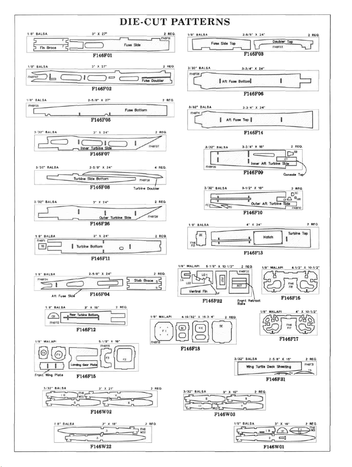
Die Patterns..................................6
Get Ready to Build.......................7
TAIL FEATHERS ........................7
Build the Fins and Rudders..........7
Build the Stabs and Elevators ......8
Temporarily Install Hinges ..........9
WING.............................................10
Spars.............................................10
Build the Wing Panels..................10
FINAL ASSEMBLY .......................42
Install Wing Tips ...........................43
Install Ailerons ..............................43
Install Aileron Servo......................44
Install Exhaust Nozzles .................45
Cut Main Gear Retract Openings ..46
FINISHING....................................47
Blend Wing to Fuse .......................47
Instrument Console & Seats ..........47
Prepare Canopy..............................47
Balance the Airplane Laterally ......48
Final Sanding.................................48
Covering ........................................48
Glue Fins and Stabs in Place .........49
Glue Aileron Hinges......................49
Glue Elev. and Rudder Hinges ......49
Assemble the Two Panels ............12
Install the Wing Sheeting.............14
Install the Aileron Torque Rods... 18
FUSELAGE ASSEMBLY............19
Prepare the Sides..........................19
Prepare the Firewall .....................21
Assemble Fuselage.......................21
Landing Gear (Fixed)...................23
Landing Gear (Retracts)...............25
General Fuselage Assembly.........27
Install the Nose Gear Retract .......28
Install Radio .................................29
Retract Pushrods ..........................30
Pushrods.......................................31
Drill Engine Mount......................34
Install Fuel Tank...........................35
Install Cockpit................................50
Decals and Trim.............................50
Wing Seating .................................51
Re-install Engine and Radio..........51
Balance Your Model ......................51
Final Hookups and Checks............53
PRE-FLIGHT.................................53
Charge the Batteries.......................53
Find a Safe Place to Fly.................53
Ground Check the Model ..............53
Range Check Your Radio ..............53
Engine Safety Precautions.............53
AMA Safety Code.........................54
FLYING..........................................54
Takeoff...........................................54
Flying............................................54
Final Fuselage Construction.........35
Fit the Wing to the Fuselage ........37
Build the Wing Turtle Deck.........39
Engine Compartment ...................40
Important Caution..........................55
Landing..........................................55
Control Surface Throws.................55
2-VIEW............................................56
Page 3
WARNING! THIS IS NOT A TOY!
THIS IS NOT A BEGINNERS AIRPLANE!
This R/C kit and the model you will build is not a toy! It is capable of serious bodily harm and
property damage IT IS YOUR RESPONSIBILITY AND YOURS ALONE — to build this kit
correctly, properly install all R/C components and flying gear (engine, tank, pushrods, etc ) and to
test the model and fly it only with experienced, competent help, using common sense and in
accordance with all safety standards as set down in the Academy of Model Aeronautics Safety Code
It is suggested that you join the AMA and become properly insured before you attempt to fly this
model IF YOU ARE JUST STARTING R/C MODELING, CONSULT YOUR LOCAL HOBBY
SHOP OR WRITE TO THE ACADEMY OF MODEL AERONAUTICS TO FIND AN
EXPERIENCED INSTRUCTOR IN YOUR AREA
Academy of Model Aeronautics
5151 East Memorial Drive
Muncie, IN 47302-9252 (800) 435-9262
INTRODUCTION
Congratulations and thank you for purchasing the
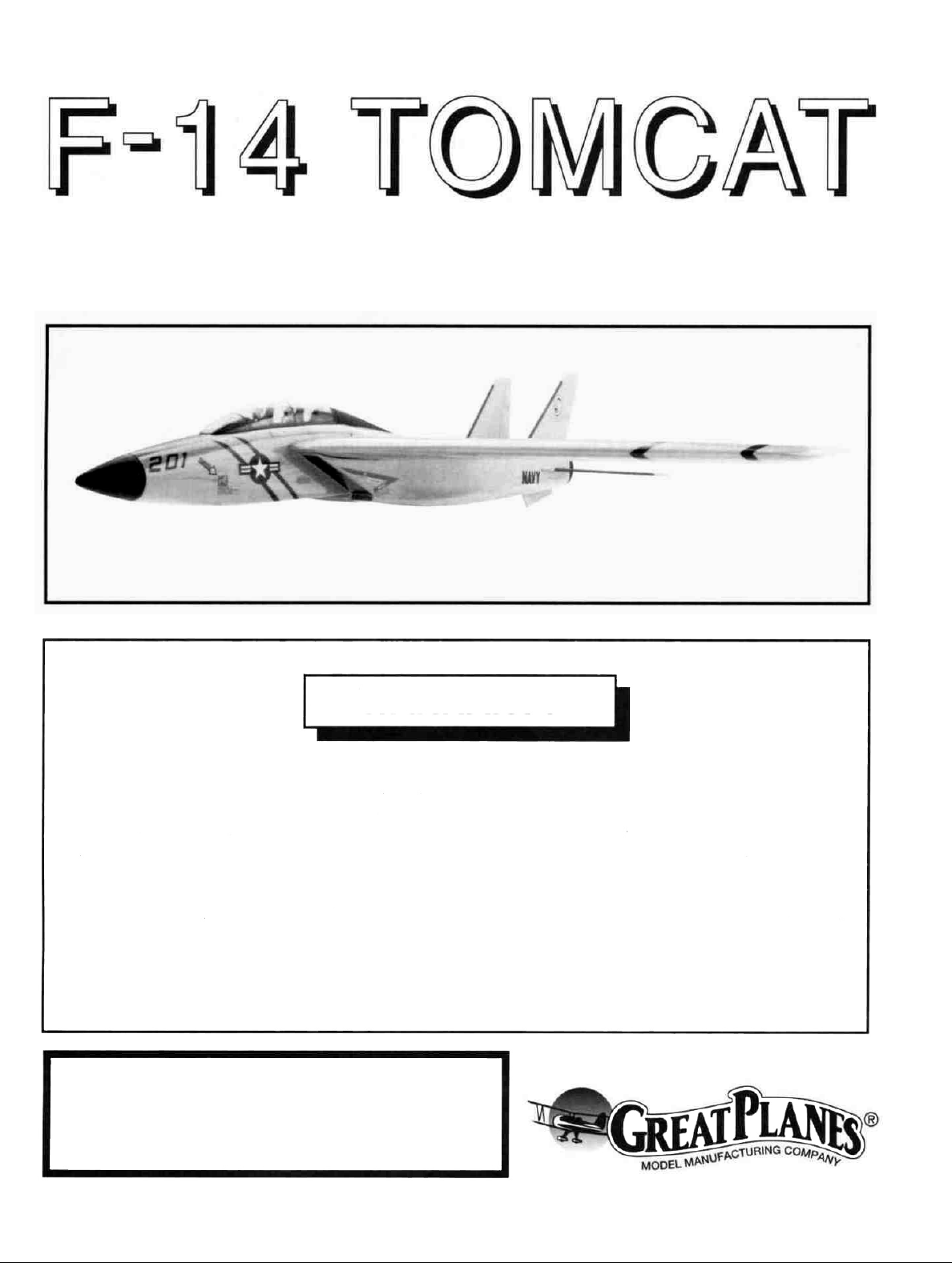
Great Planes F-14 TOMCAT'
The Great Planes F-14 is a high performance
propeller-driven sport airplane that resembles the real
F-14 Tomcat In the air, the prop is invisible, adding to
the realism The smoothness and speed of this airplane
allow you to experience the thrills of flying a jet-like
airplane without the complexity and high cost of a dueled
fan model
This is not a beginner's airplane! While the F-14
TOMCAT is not difficult to build and flies great, we
must discourage you from selecting this kit as your first
R/C airplane It is very fast, highly maneuverable and
lacks the self-recovery characteristics of a good basic
trainer such as the Great Planes PT Series airplanes
On the other hand, if you are confident with your flying
skill and can safely handle aileron airplanes such as the
Great Planes Ultra-Sport Series or Big Stik Series
airplanes, the F-14 is an excellent choice. If you
currently fly an aileron airplane but you are unsure about
your ability to handle the F-14. we recommend that you
build and fly a low-wing sport plane before building and
flying your F-14
Please inspect all parts carefully before
starting to build! If any parts are missing,
broken or defective, or if you have any
questions about building or flying this
airplane, please call us at (217) 398-8970 and
we'll be glad to help. If you are calling for
replacement parts, please look up the part
numbers and the kit identification number
(stamped on the end of the carton) and have
them ready when calling.
PRECAUTIONS
1. You must build the plane according to the plans
and instructions. Do not alter or modify the model as
doing so may result in an unsafe or unflyable model In
a few cases the plans and instructions may differ slightly
from the photos In those instances you should assume
the plans and written instructions are correct Also you
may notice a slight difference in length between longer
parts and the plans This is normal and is caused by the
plans expanding and shrinking with the changing
moisture content in the an Do not modify the paits to fit
the plan
2 You must take time to build straight, true and
strong IMPORTANT - Glue should never be
substituted tor a good joint Take a little extra time to get
a close fitting joint and glue it properly It will be
stronger, neater, and much lighter than a bad joint held
together with a glob of glue!
3
Page 4
3. You must use a proper R/C radio that is in first class
condition and meets the current AMA and FCC
requirements and the requirements of your local flying
club, the correct sized engine and correct components
(fuel tank, wheels, etc )
4. You must properly install all R/C and other
components so that the model operates properly on the
ground and in the air
5. You must test the operation of the model before the
first and each successive flight to insure that all equipment
is operating Also you must make certain that the model
has remained structurally sound
6. You must fly the model only with the competent
help of a well experienced R/C pilot if you are not already
an experienced and knowledgeable R/C pilot.
Note We, as the kit manufacturer, can provide you with a
top quality kit and great instructions, but ultimately the
quality and flyability of your finished model depends on
how you build it, therefore, we cannot in any way
guarantee the performance of your completed model, and
no representations are expressed or implied as to the
performance or safety of your completed model
Remember: Take your time and follow
directions to end up with a well-built model that
is straight and true.
OTHER ITEMS REQUIRED
D Four-channel radio with 4 or 5 servos (additional channel
and retract servo required if retracts are being used)
D Propellers (see engine instructions for recommended
sizes) Top Flite® "Power Props" recommended.
D 2-1/4" Spinner (Hobbico 2-1/4" Jet spinner #HCAQ3750
recommended)
D Fuel Tank (GPMQ4104)
D 5/32" Wheel Collars (GPMQ4306)
D Iron-on Covering Material (Top Flite Super MonoKote®
gray, black and cub yellow recommended)
D Fuelproof Paint for Tail Cones, and possibly for trim
Note Chevron "Perfect Paint" matches Top Flite Super
MonoKote, and is available in spray cans.
D 36" Throttle Pushrod (GPMQ3710)
D Silicone Fuel Tubing (GPMQ4131)
D 1/16" thick Wing Seating Tape (GPMQ4422) or silicone
sealer see instructions
D Latex Foam Rubber Padding (HCAQ 1000)
D 2 Plastic Pilots Williams Bros Military 1-1/2" Scale #171
D Wheels (see page 5)
THE OPTIONAL RETRACTS ALSO REQUIRE:
D Hobbico Low-Profile Retracts (HCAP4000)
D #2 X 3/8" Socket Head Screws (GPMQ3120)
D Dubro #103 Strip Aileron Horn (DUBQ1780)
D Nose Gear Retract Pushrod (A Sullivan red outer
guide tube and a 34" threaded rod works well for this)
D Three 3/32" Wheel Collars (GPMQ4302)
D Screw-Lock Pushrod Connector (GPMQ3870)
D 2-56 Metal Clevises (GPMQ3790)
SUPPLIES AND TOOLS NEEDED
D 2 oz Thin CA Adhesive (GPMR6003)
D 2 oz Medium or Thick CA Adhesive (GPMR6009)
D 2 5 oz Epoxy (GPMR6047)
D Silicone Adhesive
D 7/64 Ball Driver (GPMR8003)
D 440Tap(GPMR8101)
D Hand or Electric Drill
D Drill Bits 1/16", 5/64", 7/64", 1/8", 5/32", 3/16",
13/64", 1/4" and 5/16"
D Sealing Iron and Heat Gun (Hobbico or Top Flite
recommended)
D Hobby Saw (X-acto Razor Saw)
D X-acto Knife, #11 Blades
D Pliers
D Screw Drivers
D T-Pins (HCAR5200)
D Straightedge
D Masking Tape (Required for construction)
D Sandpaper (coarse, medium, fine grit)*
D T-Bar Sanding Block (or similar)
D Waxed Paper
D Lightweight Balsa Filler
D Vaseline Petroleum Jelly
D Isopropyi Rubbing Alcohol (70%)
D 3M "77" Spray Adhesive (optional)
D Dremel Moto Tool or similar (optional)
D 5/64 and 2mm Ball Driver (for Hobbico Retracts)
*NOTE: On our workbench, we have four 11" T-Bar
sanders, equipped with #50, #80, #100 and #150-grit
sandpaper. This setup is all that is required for
almost any sanding task. We also keep some #320grit wet-or-dry sandpaper handy for finish sanding
before covering.
4
Page 5
DECISIONS YOU MUST MAKE NOW
ENGINE, MOUNT AND MUFFLER
SELECTION
The recommended engine for the F 14 is a 60* - 75
cubic inch displacement 2-cycle *NOTE: Performance
may be marginal if a non-Schneurle-ported 60 cu in
2-Cycle engine is used. The engine you select will
determine how you build the fuselage, so it is important
that you have the engine close at hand while building
Because of the size limitations and the nature of this
model, 4-cycle engines are more difficult to install and
balance and therefore are not recommended.
This kit includes a Great Planes MM60 engine mount
(or similar mount) that fits most 60 - 61 (2-Cycle)
engines (slight modification of this mount is required to
mount the OS 61 SF by filing the inside edges of the
engine mount beams) If the supplied mount can't be
modified to fit your engine, it may be necessary to
purchase a different mount (check with your hobby
dealer).
SELECTION OF WHEELS
To save weight, we recommend using lightweight
wheels REMEMBER: Large wheels are ugly and
unrealistic on a model of this type, so try to keep the
wheels as small as possible.
POSSIBLE RADIO INSTALLATIONS
The F-14 is designed to satisfy a wide variety of
modelers' desires The following radio installation
options will allow you to customize the plane to fit
whichever radio you want to use.
Our recommended radio installation requires 5
standard servos and a 180 degree retract servo (if retracts
are used) This will allow you to use one standard servo
for the rudders, two servos for the elevators (one for
each), one for the throttle and one for the ailerons This
set-up will give you very precise control and is easy to
install
You can also fly the plane with 4 standard servos by
using only one servo to drive both elevators In this case
the elevator servo is mounted up in a front servo tray and
two long pushrods are used This will work Ok, but there
is generally more "play" in the elevators (due to the
longer, curved pushrods) This method is not
recommended if you intend to use a high powered engine
or do a lot of high speed flying
Both rudders can be operated from one servo without
any problems because their linkage is much straighter If
you don't plan on doing much acrobatic flying, you can
even get by with only one operating rudder In this case
you would just run one pushrod straight back to the
rudder on the same side as the servo The other rudder
would be glued on to the fin and would not move
If you will be flying from a concrete or asphalt runway, we
recommend 2-1/4" main wheels and a 2" nose wheel
For grass fields, larger wheels will be required, such as 2-1/2"
main wheels and a 2-1/4" to 2-1/2" nose wheel.
If you will be installing retracts, you should try to limit the
wheel size to a maximum of 2-1/4" main wheels and a 2" nose
wheel or the wheel wells will be excessively large.
COMMON ABBREVIATIONS USED IN
THIS BOOK AND ON THE PLANS:
Elev = Elevator
Fuse = Fuselage
LE = Leading Edge (front)
LG = Landing Gear
Ply = Plywood
Stab = Stabilizer
TE = Trailing Edge (rear)
= Inches
RETRACTABLE LANDING GEAR (optional)
This airplane flies very well with a fixed landing gear,
and retracts are not necessary, however, they do add
realism and speed, and are a nice addition (it you are
prepared for the extra work involved in their installation)
Since the retracts are all located in the fuselage, one
retract servo (such as the Futaba FP-S136G) can be used
to actuate all three retracts
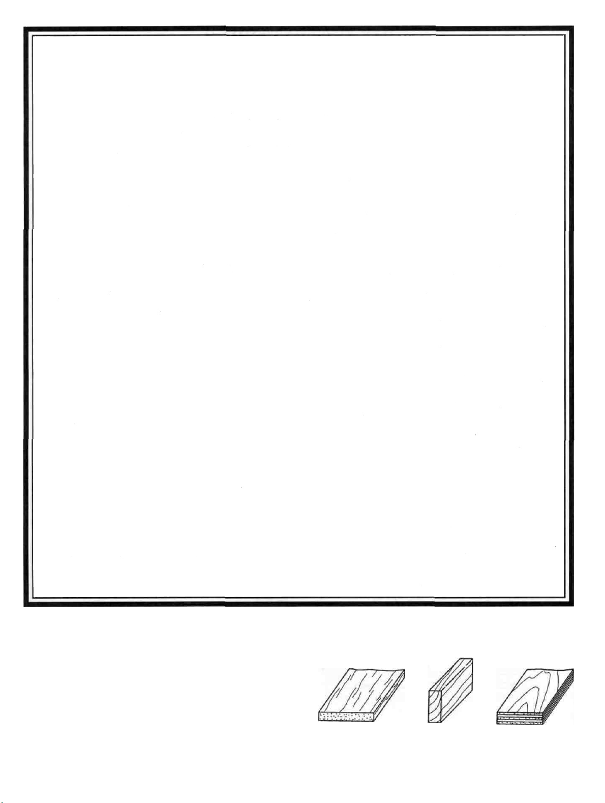
TYPES OF WOOD
Balsa Basswood Plywood
Page 6
6
Page 7
GET READY TO BUILD
D 1. Unroll the plan sheets and re-roll them inside
out. This will help them lie flat.
D 2. Remove all parts from the box. As you do,
determine the name of each part by comparing it with the
plans and the parts list at the back of this book. Using a
felt tip pen, write the part name or size on each piece to
avoid confusion later. Use the die-cut part patterns
shown on page 6 to identify the die-cut parts, but do not
punch them out until you are ready to use them. Save
all scraps. If any of the die-cut parts are difficult to
punch out, do not force them! Instead, first cut around
the parts with an X-acto knife. After punching out the
die-cut parts, use your T-Bar or sanding block to lightly
sand the edges to remove any die-cutting irregularities.
D 3. As you identify and mark the parts, separate
them into groups, such as fuse (fuselage), wing, fin and
stab (stabilizer), and hardware.
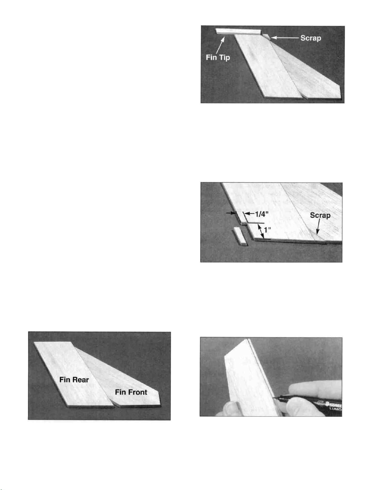
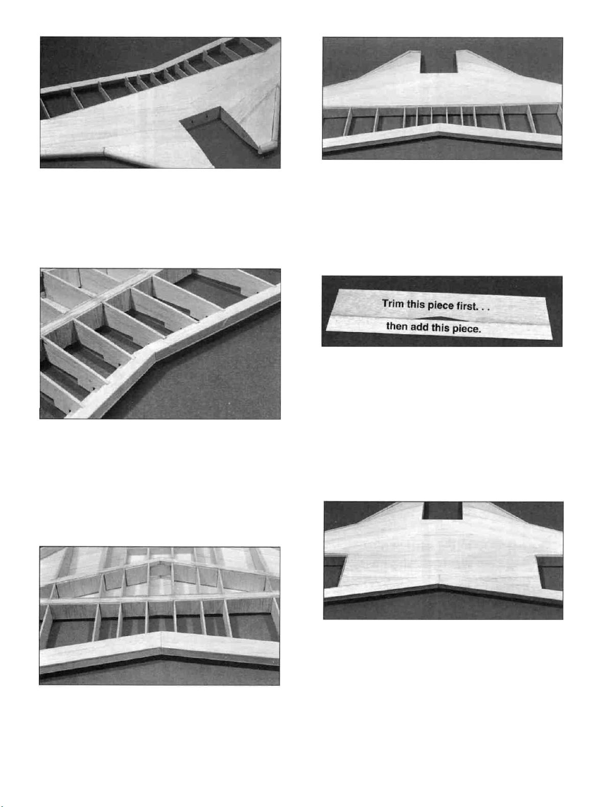
D D 3. Cut the tip of the fin rear to match the leading
edge sweep of the fin front. Glue the little triangle piece
of scrap into the "V" at the bottom. Cut the 1/4" x 5/8"
x 9" balsa stick (F146R04) in half to make two 4-1/2"
long fin tips. Glue the tip in place at the end of the fin
rear.
"TAIL FEATHERS"
BUILD THE FINS AND RUDDERS
D 1. Tape the fuselage side view portion of the plan
down onto your flat work surface. Tape a piece of waxed
paper over the fin and rudder portion of the plan.
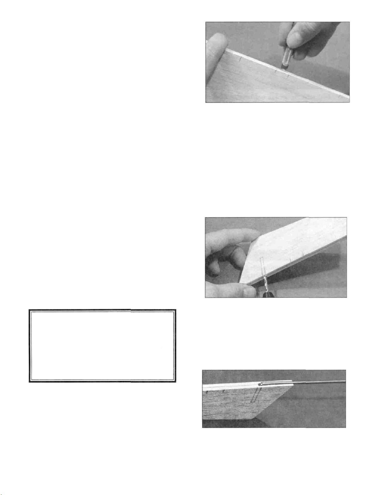
D D 4. Draw a line parallel with the trailing edge of
the fin and 1/4" in front of it. Draw another line parallel
with the bottom edge of the fin and 1" above it. Cut out
a clearance notch for the torque rods using the lines as a
guide as shown in the photo.
D D
2.
Glue
the
1/4"
balsa
fin from
the 1/4" balsa fin rear (F146R03) so their bottoms are
even with each other. Note that there will be a triangle of
wood missing between the two pieces. This can be filled
in the next step.
(146R01)
to
D D 5. Use a sanding block with medium (150) grit
sandpaper to sand the edges and both sides of the stab
smooth. Carefully draw a centerline all around the
edges of the stab and elevator. This will make it easier to
maintain symmetry when sanding later.
7
Page 8
D D 6. Using a sanding block and coarse (50 or 80-
grit) sandpaper, sand both sides of the rudder to a taper
(see cross-section on plans). The trailing edge should
end up approximately 3/32" wide. (Do not sand to a
sharp edge). Leave the top and bottom edges square.
Sand the leading edge of the rudder to a "V-shape" as
shown on the plan. NOTE: If you are going to have
only one operating rudder, do not sand the LE of the
fixed rudder to a "V" as described above. Leave it
square and Just glue it in place against the TE and tip of
the fin. HINT: It is a good idea to keep new, sharp
sandpaper on your sanding blocks. You will notice that it
"cuts" the wood and the glue much cleaner and produces
a much smoother finish.
D D 7. Sand the top and front edges of the fin to a
rounded shape (see cross-section on plans). Sand the
trailing edge of the fin tip (at the top of the rudder) to the
same taper as the rudder.
D 8. Go back to step 2 and build another fin and
rudder.
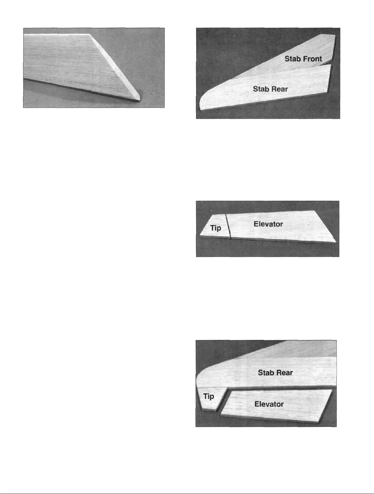
D D 2. Glue the 1/4" balsa stab front (F146S01) to
the 1/4" balsa stab rear (F146S03) so the root ends are
even with each other. Note that there is a triangle of
missing wood formed when the two pieces are properly
joined. There are no scrap pieces to fit in there. You can
cut one if you desire, although it is not necessary.
D D 3. Position the 1/4" balsa elevator (F146S04)
over the plan and mark where the stab tip will be cut oft.
Cut the tip off with a razor saw and glue it to the stab
rear. Do this over the plans so you will be sure to
position it correctly.
BUILD THE STABILIZERS AND
ELEVATORS
D 1. Tape the fuselage top view portion of the plan
down onto your flat work surface and cover the stabilizer
portion of the fuselage top view with wax paper.
D D 4. Use a sanding block with medium (150) grit
sandpaper to sand the edges and both sides of the stab
smooth. Carefully draw a centerline all around the
edges of the stab and elevator. This will make it easier to
maintain symmetry when sanding later.
8
Page 9
D D 5. Using a sanding block and coarse (50 or 80-
grit) sandpaper, sand both sides of the elevator to a taper
(see cross-section on plans). The trailing edge should
end up approximately 3/32" wide. (Do not sand to a
sharp edge). Leave the ends square. Sand the leading
edge of the elevator to a "V-shape" as shown on the
plan.
D D 6. Sand the tip and front edges of the stab to a
rounded shape (see cross-section on plans). Sand the
trailing edge of the stab tip to the same taper as the
elevator.
D D 7. Draw a line parallel with the trailing edge of
the stab and 1/4" in front of it. Draw another line
parallel with the root edge of the stab and 1" out from it.
Cut out a clearance notch for the torque rods just as you
did on the fins earlier.
D 8. Go back to step 2 and build another stab and
elevator.
B. Make three or four more cuts in the same line, going
slightly deeper each time. As you make these
additional cuts. work on going straight into the wood.
Continue this process while "wiggling" the knife
handle forward and backward until the blade has
reached the proper depth for the hinge.
C. Trial fit the hinge into the slot. If the hinge is
difficult to push in. re-insert the knife and move it
back and forth in the slot a few times to enlarge the
slot. Do not glue the hinges yet.
TEMPORARILY INSTALL HINGES
AND TORQUE RODS
D 1. Using the plans as a guide, mark the hinge
locations on the stabs, elevators, fins and rudders. Also
designate one of each surface as being "right" and the
others as "left."
CAUTION!!! You must use extreme care when
cutting hinge slots with an X-acto knife, to
avoid cutting yourself! If the balsa part breaks
while you are pushing on the knife, the blade
could go into your hand before you know it! A
good precaution is to wear leather gloves while
performing the following steps.
D 2. Cut the hinge slots on the centerlines you drew
earlier. Our recommended hinge slotting method is
described below.
D 3. Check the plans and mark the location of the
torque rods on the rudders and elevators. Drill 7/64"
holes in the rudders and elevators (the holes are drilled
slightly oversize to allow for positioning, and to create a
hard epoxy "sleeve" around the wire). Groove the rudder
and elevator LE to accept the torque rod wires and nylon
bearings (See below).
A. Begin by carefully cutting a very shallow slit at the
hinge location. The first cut is to establish your cut in
the right place, so concentrate on staying on the line
and don't cut too deep.
HINT: Using an X-acto knife, sharpen the inside of one
end of a 1/8" diameter brass tube. and use it to cut the
groove in the leading edge of the rudders and elevators.
9
Page 10
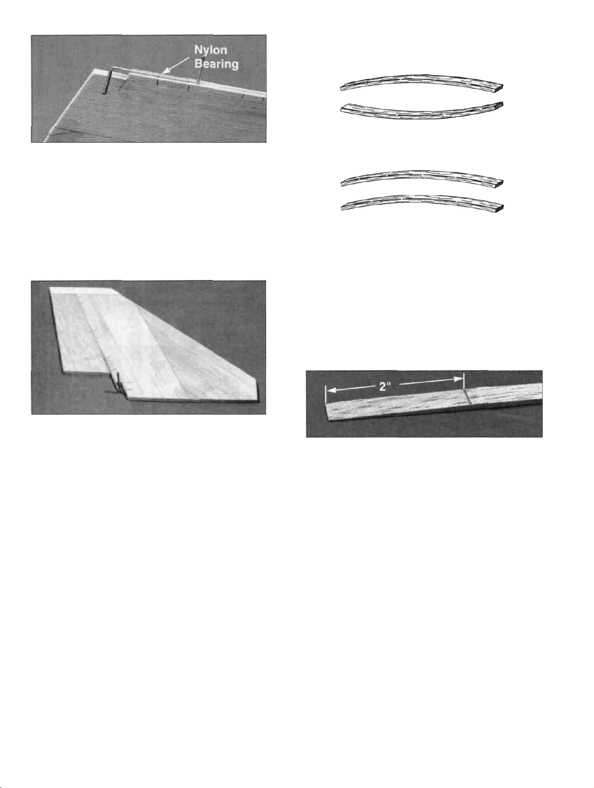
D 4. Determine the torque rod bearing locations
from the plan. Then use a hinge slotting tool to cut the
slots in the stabs and fins tor the nylon torque rod
bearings. Cut a groove in the trailing edge of the stabs
and fins to accept the torque rods and nylon bearings.
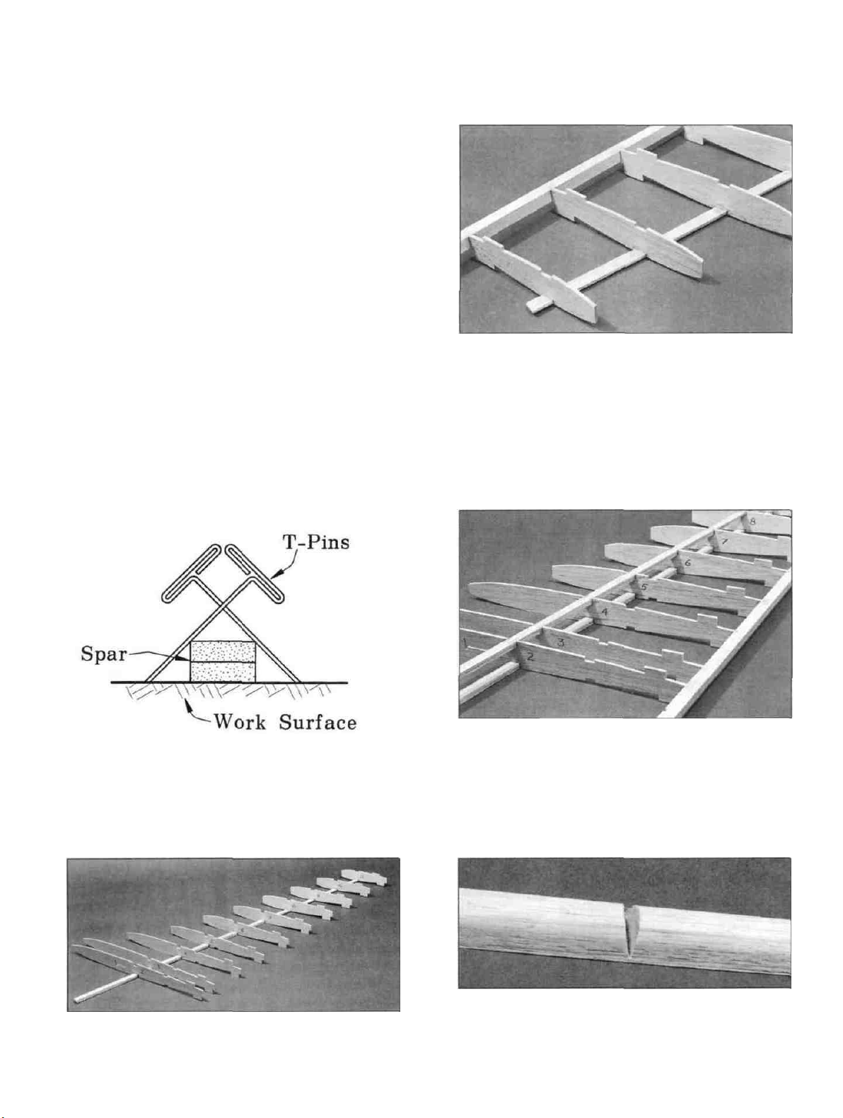
TWO WARPED SPARS INSTALLED
THIS WAY WILL RESULT IN A
STRAIGHT WING
TWO WARPED SPARS INSTALLED
THIS WAY WILL RESULT IN A
WARPED WING
imperfections. If possible, position each spar so the
imperfections (if any) are on the outer half of the wing
panel (toward the tip), where they will be least affected
by high stress. If the spars are warped slightly, try to
"balance them out" by installing the warped spars in
opposite directions (see sketch). NOTICE: If you feel
that any of the wing parts are unusable due to severe
warps or other defects, give us a call and we'll replace
the parts.
D 5. Trial fit all these parts together using the torque
rods and hinges and trim the fin tips flush with the
trailing edges of the rudders. Check the operation of the
control surfaces but do not glue anything yet.
"WING"
NOTE: The following instructions explain how to build
the wing on a flat surface, directly on the plans. The jig
tabs will automatically build in 1-3/4 degrees of washout
and enable you to build a wing as straight as your work
surface. Because this wing has a lot of taper and sweep,
it is not advisable to build it on a Great Planes Wing Jig.
SPARS
D 1. Before using the hard balsa spars, examine
them carefully for possible imperfections. Look for
knots, soft spots, diagonal gram and any other
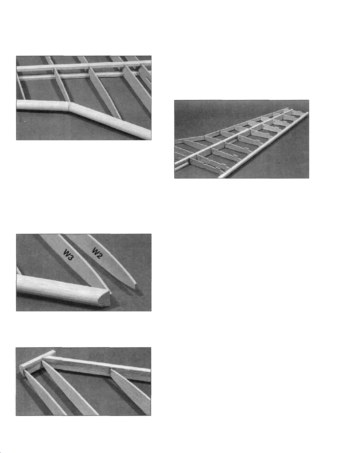
D 2. Sand 2" of one end of each 1/8" x 3/8" x 18"
balsa spar doubler (F146W05) to a taper as shown in
the "Wing Spar Detail" on the plan.
D 3. Glue the spar doublers to the 1/8" x 3/8" x 30"
balsa spars (F146F04) with thick CA as shown in the
"Wing Spar Detail." Take your time and press the spar
assembly flat against the work surface while the glue is
curing. Also rotate the assembly onto its side and press
it down to keep the doubler and spar aligned and straight.
Do this on a flat work surface and most warps can be
eliminated. Wipe off any excess glue before it cures.
BUILD THE WING PANELS
NOTE: If you build in the conventional manner, by
pinning the components to your workbench, it will be
helpful to build the wing on a piece of "Celotex"* or
10
Page 11
other semi-soft (and flat) surface, into which you may
easily stick pins to firmly hold down the wing parts
while building, to avoid warps. *Available from lumber
companies and home centers.
NOTE: You should also be aware of the following:
This wing is constructed with 1-3/4 degrees of washout
(TE higher than LE at the wing tip) built-in. When the
wing is upright, the tabs on the rear portion of the ribs set
the ribs at the proper angles to achieve this slight twist.
When you flip the wing over to work on the bottom side,
the jig tabs on the top of the wing will hold the correct
washout in the wing.
D D 1. Cut the Wing Plan apart on the heavy dashed
line. Tape the right (or left) wing panel plan to your flat
work surface, and cover the wing drawing with waxed
paper (so you won't glue the wing to the plan!).
D D 2. Carefully punch out all the die-cut 3/32" and
1/8" balsa wing ribs. Sand the edges slightly to remove
any die-cutting irregularities or "fuzz."
with the rear-most jig tab against the work surface.
Use a 90-degree triangle to keep the ribs vertical.
D D 5. The shaped and notched wing trailing edges
(F146W07) are fastened together by a thin strip of balsa.
Separate them by cutting with an X-acto knife. Position
the TE in place by working the rear ends of the ribs into
the notches in the TE. Center the TE vertically on each
rib and glue it in place with thin CA.
D D 3. Cross-pin one of the spars to the plan with the
long spar down. and with the thick end (2 laminations)
toward the root. The tapered end of the spar doubler
should end just inside (1/4") of rib W8.
D D 4. Glue ribs W2 through W11 onto the spar in
their correct position. Notice that the ribs are installed
D D 6. Glue the top spar in place (with the long spar
on top). Make sure it is fully seated in the notches so it
does not stick above the top surface of the ribs.
Remember, the spar doubler stops just inside rib W8.
D D 7. Position a shaped balsa Leading Edge
(F146W06) over the Leading Edge Template on the wing
plan and mark where the notch goes. Use a razor saw to
11
Page 12
cut the notch. Make sure you cut the notch perpendicular
to the LE and notice that it does not need to go all the
way through the LE.
D D 8. Glue the LE to rib W5 so the notch is
positioned as shown on the plan and the LE is centered
(up and down) on the rib. Center the LE on ribs W6
through W11 and glue it in place with thin CA. Next,
glue the LE to rib W3 and lastly to rib W4. The LE may
break in two during this step, but this is OK, just glue it
back together as you perform the step. IMPORTANT -
Use the plans as a guide to keep the front of rib W3
positioned correctly.
W3 and the slanted piece of LE already installed. Trim
the LE flush with W2 and the slanted piece of LE.
NOTE: In the following steps you'll find it necessary to
remove some of the pins holding the wing down to your
building board. As you do, take other steps as necessary
to continue holding the wing down, such as by applying
weight to the top of the wing, or by relocating the pins.
D D 11. Glue the pre-cut 1/16" balsa vertical grain
shear webs to the rear edge of the spars in all rib bays
except inside of rib W2 and between ribs W5 and W6.
Also glue shear webs on the front edge of the spars in
the first 5 rib bays starting with the W2-W3 bay.
NOTE: You may wish to trial fit, mark, and trim each
web before gluing it in. The webs must be securely
glued to the spars.
D D 9. Cut the excess LE off flush with the front of
rib W3. Sand it if necessary to get the face of the LE cut
aligned with rib W2.
D D 10. Glue the remaining piece of LE to ribs W2,
D D 12. Trim the tip end of the LE, TE and spars off
flush with rib W11.
D D 13. Trim off the root end of the spars and TE
slightly longer than their correct length (approx. 1/64"
longer). Later, when the two wing halves are joined,
they will be sanded to the correct length. Remove the
wing panel from the work surface.
D 14. Go back to step 1 and assemble the other wing
half. Be sure to build a right wing and a left wing!
ASSEMBLE THE TWO PANELS
D 1. Cut out the two dashed semi-circles on the left
wing plan. Place the left wing plan over the right wing
plan and carefully line-up the centerlines of each plan.
Tape the two plans together. Test fit the two panels
together over the plans and sand the spars and TE as
necessary until you achieve the proper spacing and wing
sweep. Insert the die-cut 1/8" ply front wing plate
(F146F15) and the 1/4" x 1" x 4-13/32" ply front wing
12
Page 13
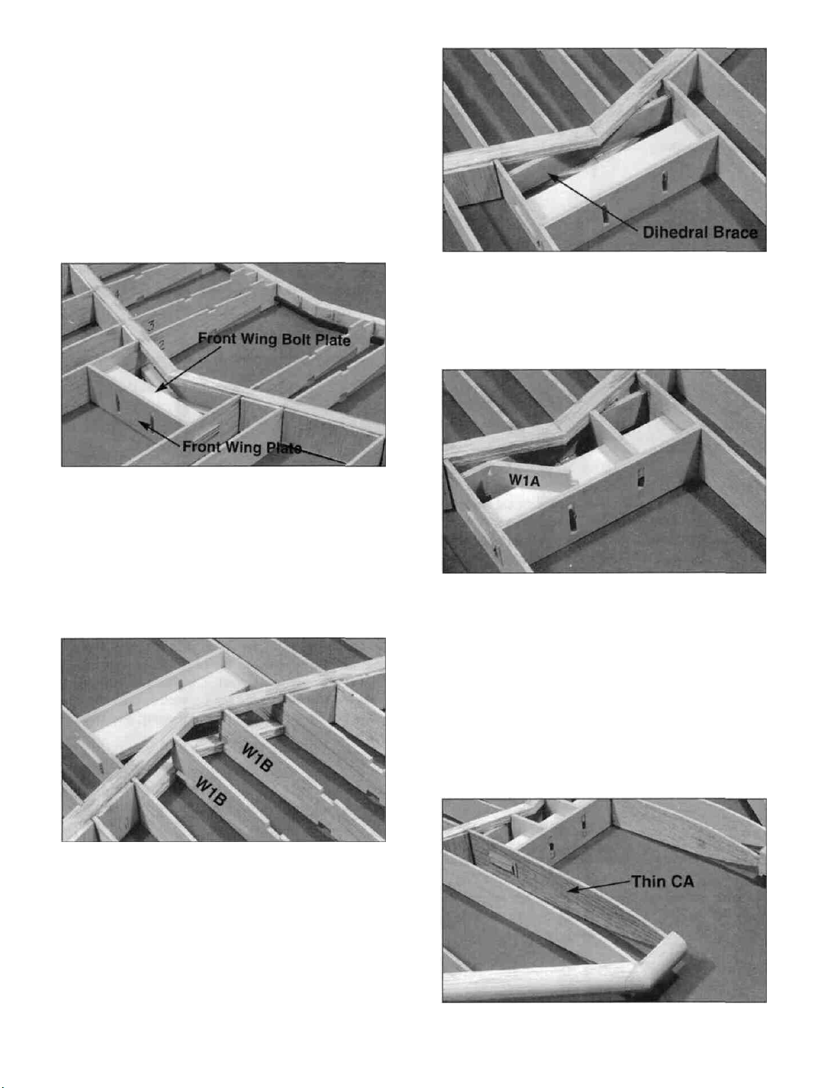
bolt plate (F146W18) to check the spacing. Make sure
both panels are on a flat surface and lined up correctly
with the jig tabs against the work surface. Refer to the
plans and the following photo. NOTE: The notches for
the middle spar should form a straight line when the
proper amount of sweep is achieved.
D 4. Securely glue the 1/8" x 23/32" x 4-5/32" ply
dihedral brace (F146W12) in place between the spars
and against the W1B ribs with epoxy.
D 2. When satisfied with the fit of the two panels,
insert the front wing bolt plate along with the wing front
plate into the slots in the W-2 ribs and glue the spars and
TE'S together with epoxy. Also glue the plates in place.
D 3. Install the die-cut 1/8" balsa W1B ribs
(F146W01) by inserting them into the trailing edge slots
and rotating them until the front notches contact the
spars. Make sure the aileron servo rail slots in the ribs
are positioned down (near the work surface) and glue
them in place.
D 5. Slide the die-cut 1/8" ply W1A ribs (F146F32)
into place by positioning them at an angle as shown on
the left side of the photo and rotating them until they fit
into place as shown on the right side of the photo. Be
careful not to push the wing front plate out away from
the wing bolt plate during this step. Sand the inside slot
of the W1A ribs if they are hard to slide over the wing
bolt plate. Glue all these pieces together with thin CA
followed by either epoxy or thick CA.
13
D 6. Soak the entire outer side of each W2 rib with
Page 14
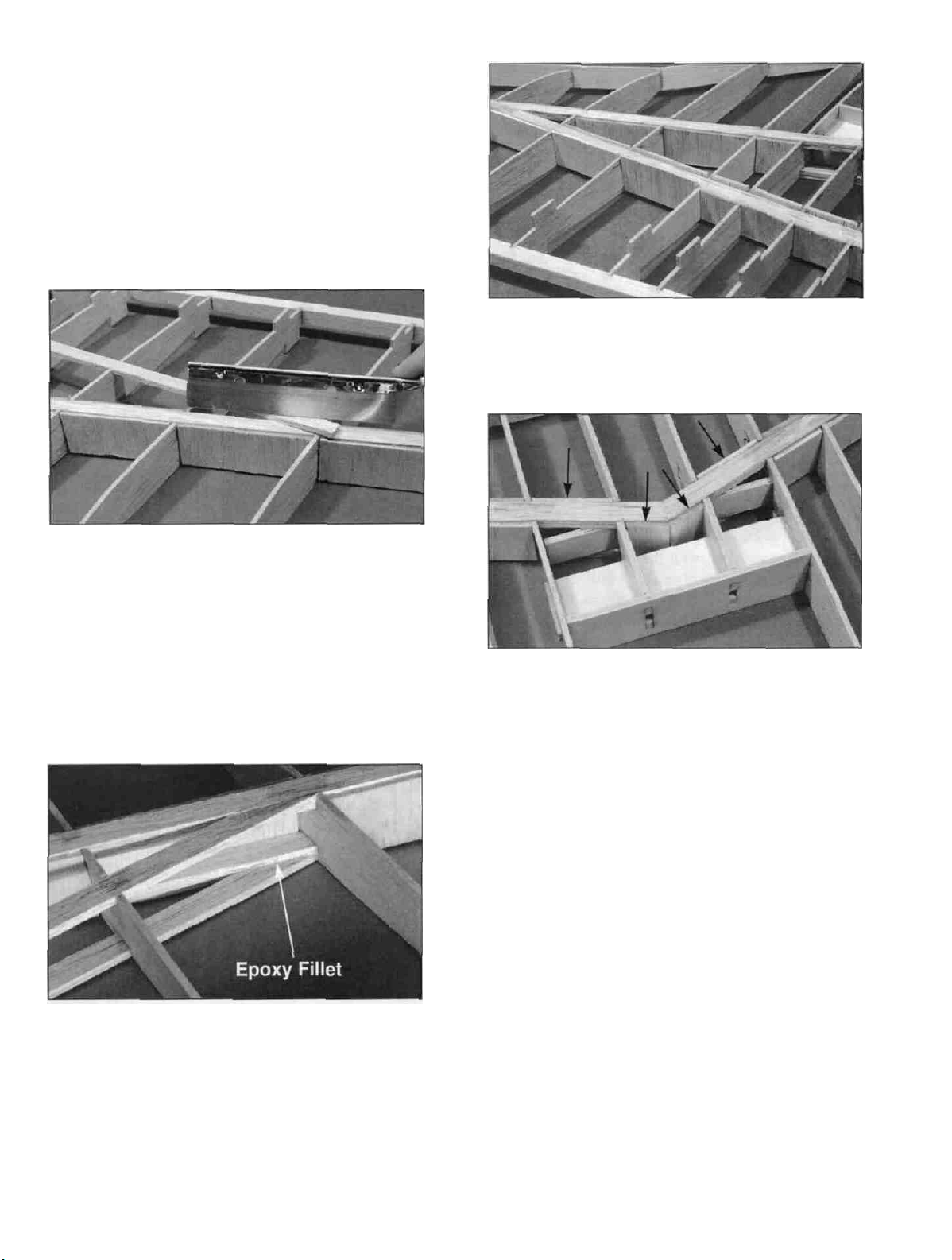
thin CA to help harden the wood. Cut four 1" long
pieces of 1/2" triangle from the 1/2" x 36" triangle
(WSTR001H) and glue them in place above and below
the front wing bolt plate and against the W2 ribs. Add
epoxy or thick CA around every joint in this area to
make sure everything is securely glued in place.
of the middle spar in all rib bays. The shear webs will be
too tall and too wide, so just trim them to fit and securely
glue them in place.
D 7. Trim the 1/8" x 3/8" x 24" balsa top middle
spar (F146W17) to fit in place by positioning it in the
notches and using a razor saw to accurately cut the taper
on both ends. NOTE: It is important to get the best
joint possible between the middle spars and the main
spars. Securely glue the middle spar in place with epoxy.
D 8. Flip the wing over and install the 1/8" x 3/8" x
24" balsa bottom middle spar just as you did the top
one in the last step. Make a nice epoxy fillet where both
middle spars contact the main spars.
D 10. Cut pieces of shear webs to lit in the three center
bays of the main spar and securely glue them in place.
D 11. Cut two 1-1/2" long aileron servo rails from
the 1/8" x 3/8" x 15" basswood strip (F146F30). Slide
these into the slots in the W1 ribs and use your aileron
servo to properly space them. They should be installed
as far forward as possible and far enough apart to allow
you to get the servo in and out. Securely glue them in
place.
INSTALL THE WING SHEETING
NOTE: In the next steps, maintain straightness by
keeping the jig tabs and spar down on the flat
surface.
D 9. Turn the wing back over so the top is up and
install 1/16" balsa shear webs on the front and the back
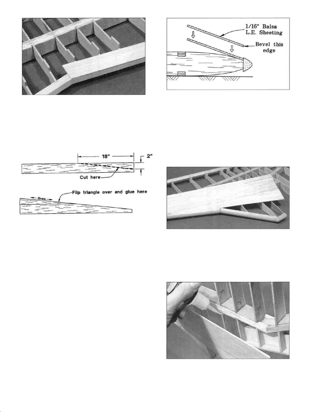
D 1. Lightly sand the tops of the ribs to blend with
the notched trailing edge, then glue the two top 1/16" x
1" x 30" balsa trailing edge sheets (F146W14) in place.
14
Page 15
NOTE: The edge of the TE sheet may not be exactly
straight, but just position the sheet so it slightly overlaps
past the TE, and any overlap can be sanded off flush with
the TE later.
D 2. Make four leading edge sheets by cutting a
triangle 2" wide on the end and 18" long off of one end
of each 1/16" x 3" x 36" balsa wing sheet (F146W13).
HINT: Use an X-acto knife and cut a straight line using a
metal straightedge. Flip the triangle over and glue it to
the rest of the sheet as shown in the sketches above.
Notice the grain direction on the small triangle.
aft edge of the sheeting is approximately in the middle of
the spar, then cut off the excess sheeting on the ends,
leaving approx. 1/4" extra to allow for positioning.
NOTE: It will be helpful to have the following items
handy for the next steps: Thin CA, thick (slow cure) CA
and a straight piece of wood (such as an aileron).
D 6. Hold the sheeting tightly against the LE at a
slight angle so it sits down on the LE of the ribs. Use
thin CA to glue the sheeting to the LE only. Do not glue
it to the ribs yet.
D 3. Sand the both sides of each LE sheet smooth
with a sanding block and fine grit sandpaper.
D 4. Before applying the leading edge sheeting in the
next steps, use your T-bar to lightly sand off the edges of
the shear webs and smoothly blend the ribs to the spar.
Also, clean up the LE/rib joints to remove any glue
globs.
D 5. Sand the front edge (the edge with the triangle
glued to it) to a slight bevel so it will fit snugly against
the back of the leading edge. Trial fit it before
proceeding. Position the sheeting left or right until the
D 7. Tilt the wing up, with the LE down, and apply a
drop or two of thick or slow curing CA to each rib. Hold
the wing at an angle so the glue will flow down and coat
the edge of each rib. Apply a line of glue to the
15
Page 16
front edge of the spar. Immediately place the wing on
your flat work surface and press the sheeting into place.
Use a piece of wood (an aileron works OK) to hold the
sheeting in place while the glue cures. It is important to
keep the wing flat during this process as the LE sheeting
will "lock" the wing together.
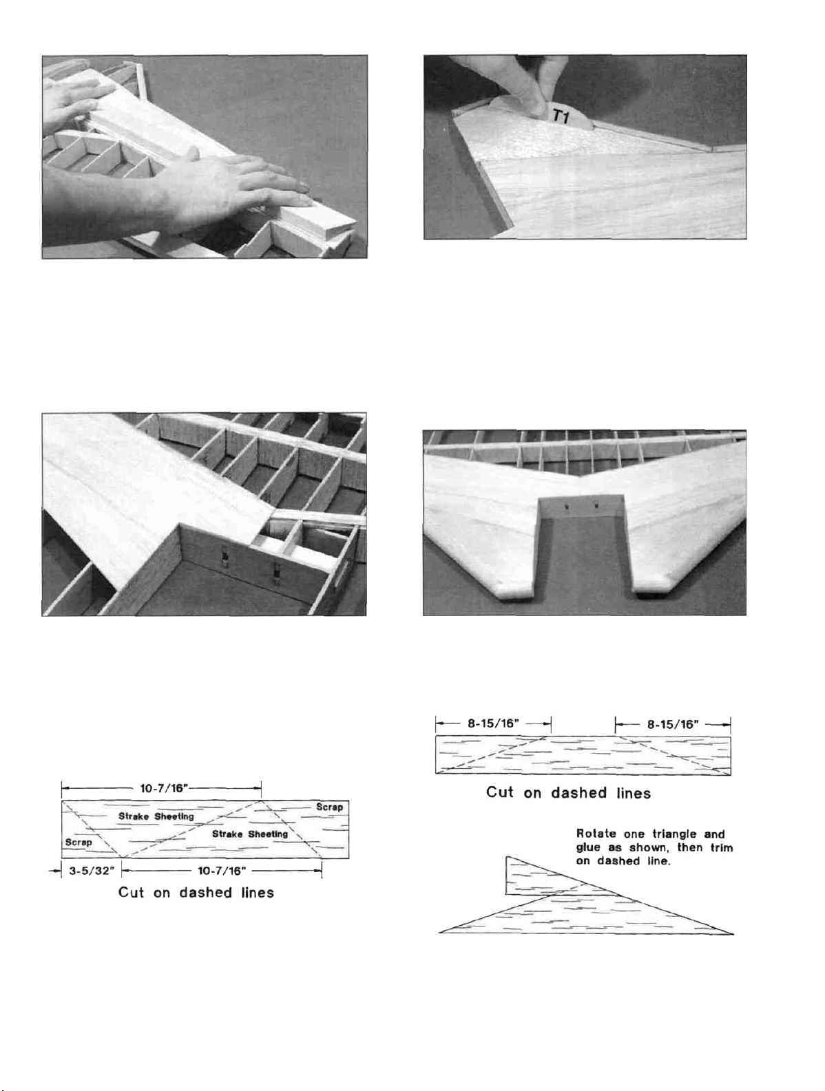
D 10. First glue the sheeting against the LE sheeting
already in place. Try to line up the edges as closely as
possible. Drip some thick CA down the ribs and press
the sheeting into place. Add CA along the LE and use a
small but flat piece of wood to keep the sheeting straight
along the LE (turtle deck former T1 works well for this).
Trim the end of the sheeting flush with rib W2.
D 8. Trim the tip end of the sheeting flush with rib
W11. Trim the root end of the sheeting flush with the
centerline of the wing, rib W2 and the wing front plate.
D 9. Cut the four pieces of 1/16" x 3" x 15" balsa
stock
sheeting
above. Test fit one of the pieces in place in front of the
leading edge sheeting and trim and sand it as necessary
to make it fit. NOTE: The grain should run along the
LE.
(F146W23)
as
shown
in
the sketch
D 11. Sheet the opposite wing panel using the same
procedure outlined above.
D 12. Cut two 1/16" x 3" x 24" balsa center sheets
(F146W15) and assemble two triangles as shown above.
Use one in the next step and save the other for the bottom
of the wing.
16
Page 17
D 13. Test fit the triangle sheeting into place and sand
it if necessary to achieve a good fit. It should go half
way back on the middle spar. Glue it in place by
applying thick or slow curing CA to the ribs and spars
and holding the sheeting in place while the glue cures.
D 14. Flip the wing over and carefully trim off the jig
tabs on the bottom of the wing (the side opposite the side
you just sheeted). Use a sanding block with a fine grit
sandpaper to touch up where the tabs were and to blend
the ribs into the TE. Be careful not to change the
shape of the ribs during this step.
D 16. Install the remaining 1/16" leading edge
sheeting, the strake sheeting and the center triangle sheet
using the same procedure outlined in steps 2-13.
D 17. Trim one of the 1/16" x 3" x 18" balsa rear
wing sheeting (F146W21) pieces to fit in place behind
the triangle center sheet. An easy way to do this is to
tape it in place behind the triangle center sheet and lay a
straight edge along the front edge of the 1" TE sheeting.
Mark where both sides of the TE sheeting continue under
the rear sheeting. Remove the rear sheeting and cut out
the triangle formed by the lines you marked. Cut another
of the rear sheeting pieces in half lengthwise and glue
one half to the rear edge of the piece you just trimmed to
fit.
D 15. Add the remaining two 1/16" x 1" x 30" balsa
TE sheets just as you did earlier on the top surface. Do
one panel at a time and keep the panel flat on the work
surface until the glue cures. Note: Due to the taper of
the wing, the jig tabs on the top surface of the wing will
only keep one panel flat at a time.
Tape the sheeting back into place and mark where the TE
sheeting intersects the outside edges. Cut the aft piece of
sheeting to fit and glue the rear sheeting in place with
thick or slow CA.
D 18. Cut a semicircle out of the sheeting between ribs
W4 and W5 as shown in the next photo.
17
Page 18

D 19. Flip the wing over. On the side that still has the
jig tabs attached, write the word "top" near the center of
the wing. Trim and sand off the remaining jig tabs.
Touch up the ribs with a fine grit sanding block and add
the rear sheeting just as you did in steps 17 and 18. Trim
all sheeting flush with the W11 ribs and lay the wing
aside until later.
rods come up through it. Cut notches there to clear the
torque rods. Test fit the wedge on the wing and sand it if
needed to get a good fit. Test fit the torque rods in the
groove to make sure they fit OK. If not, sand the groove
and notch until they do. Also cut small clearance
notches on the bottom side of the wing where the
threaded portion of the torque rod will be located. Note:
The torque rod horns must exit the BOTTOM of the
wing!
D 5. Slide the plastic bearings toward the threaded
end of the torque rods. Then use a toothpick to apply a
small amount of petroleum jelly to the ends of the plastic
tubes (to help prevent glue from getting inside and
locking up the torque rods).
INSTALL AILERON TORQUE RODS
D 1. Roughen the un-threaded end of the aileron
torque rods (WBNT167) with 100-grit sandpaper, and
file the same end to a wedge shape.
D 2. Roughen the surface of the plastic bearing tubes
with 100-grit sandpaper.
D 3. Clean the torque rods and bearing tubes with
alcohol.
D 6. Use epoxy to glue the plastic bearing tubes into
the grooves in the rear wedge. Make sure the torque rods
are fully seated in the groove. Wipe off any excess glue
and allow it to harden.
D 7. Sand the TE of the wing to make it straight with
square edges.
D 8. Trial fit the rear wedge/torque rod assembly
onto the wing trailing edge. It should be centered up and
down on the wing TE so the torque rods are located at
the centerline of the TE. Sand the TE if necessary to get
a good fit then glue the wedge in place with epoxy.
HINT: Use masking tape to hold the wedge against the
wing TE and to aid in positioning it.
D 4. Position the 1/2" balsa grooved rear wedge
(F146W10) over the plans and mark where the torque
D 9. Locate the tapered balsa center TE (F146W09)
(it is 10-1/8" long and has the same cross section as the
18
Page 19

ailerons) and cut a notch in both ends to clear the torque
rods. Also sand the very front of the ends if needed to
make it fit in place against the rear wedge. Tape it in
place with masking tape and check to make sure it is not
tilted up or down You can use the edge of a 1/8" balsa
fuse doubler (F146F02) as a template to check the
center TE alignment, but be sure to check it from the top
and the bottom of the wing When satisfied with its
alignment, glue it in place with thin CA Be very
careful around the ends so you don't glue the torque
rods!
top (F146F03), fuse side bottom (F146F01) and aft fuse
side (F146F04) together, sanding as necessary for a good
fit Make sure they line up with the plans and glue them
together.
D D 2 Assemble a 1/8" balsa fuse doubler by
gluing a die-cut 1/8" balsa doubler top (F146F03) to a
die-cut 1/8" balsa doubler bottom (F146F02).
D
10
Use some
rear wedge and center TE in with the contour of the
wing. After the filler has cured, use a sanding block to
smooth things out.
This is all we will do to the wing until after it has
been fitted to the fuselage and the turtle deck has been
added This will help keep the wing tips, cap strips and
ailerons from getting dinged up in the process.
lightweight
wood
filler
to
blend
the
FUSELAGE ASSEMBLY
PREPARE FUSE SIDES
D D 1. Working over the fuselage side view covered
with waxed paper, trial fit a die-cut 1/8" balsa fuse side
D D 3 Position the doubler on top of the fuse side
and align its edges and lightening holes with the edges
and lightening holes of the fuse side Glue the doubler to
the fuse side by applying thin CA around all edges of the
doubler, including the lightening holes NOTE: The
doubler stops 1/4" before the front of the fuse side to
hold F-l Important: Do not make two right sides'
Glue the doubler to the opposite side when making the
second side.
D D 4. Assemble a turbine inner side by test fitting a
die-cut 3/32" balsa turbine inner side (F146F07),
turbine side bottom (F146F08) and turbine inner aft
19
Page 20

side (F146F09) together over the plans Carefully sand
them if needed to achieve close fitting joints When
satisfied with the fit. add thin CA to all joints After the
glue has cured, apply thick CA to any loose-fitting joints.
D D 5. Assemble a turbine outer side by test fitting a
die-cut 3/32" balsa turbine outer side (F146F26),
turbine side bottom (F146F08) and turbine outer aft
side (F146F10) together over the plans Carefully sand
them if needed to achieve close fitting joints When
satisfied with the fit. add thin CA to all joints After the
glue has cured, add thick CA to any loose fitting joints.
Sand both sides smooth with a fine sanding block.
D D 6 Glue a die-cut 3/32" balsa turbine side
doubler (F146FOS) to the outer turbine side Line if up
with the wing saddle and add thin CA around the edges
When doing this step for the second side, make sure you
glue the doubler to the opposite side, making a right and
a left set
D 9 Carefully position a turbine inner side on each
fuse side Do this over the fuse side view on the plans
and use the wing saddle to help align them Make sure
they are correctly positioned and add thin CA around the
edges, lightening holes and former notches.
IMPORTANT - Be very accurate when doing this.
Make sure the two turbine sides are installed at the same
angle and position in relation to the sides To check this,
hold the two fuse sides together and compare the
alignment of the turbine sides before securely gluing the
second side NOTE: The turbine inner side is attached
to the fuse side, not the doubler
D 10 Test fit the two die-cut 1/8" balsa front fuse
bottom halves (F146F05) together Sand them slightly
if needed and glue them together Test fit the die-cut
3/32" balsa rear fuse bottom (F146F06) in place
D D 7 Inspect all glue joints for gaps and add thick
CA if necessary to strengthen the joints Repeat the
above steps to make another set of sides. Make sure
you assemble a RIGHT and a LEFT set of sides!
D 8 Place the two assembled fuse sides together.
Lightly sand the edges as necessary to make the two
sides identical Do the same for the turbine sides Also
sand the sides of each assembly smooth with a fine
sanding block It is rather hard to do this later'
Line up the entire bottom over the plans to keep if
straight and glue the rear onto the front Make sure both
pieces are pressed flat against the work surface Write
the word "TOP" on the side facing up (this will keep the
smooth side towards the outside of the fuse) When the
glue has cured, flip if over and sand the bottom smooth
with a tine sanding block.
20
Page 21

PREPARE THE FIREWALL (F1) ASSEMBLE FUSELAGE
NOTE: Photos show a 60-size engine mount (Great
Planes MM60 included) set up for a side mounted
2-cycle engine. If you will be using a different mount,
you'll have to determine the correct mounting position.
D 1. Locate the two 1/8" die-cut ply F-l's (F146F18)
and use a fine sanding block to remove any fuzzy edges.
Use epoxy to glue the two pieces together, making a 1/4"
thick firewall. Make sure they are accurately lined up
with one another and one of the sides with the punch
marks is showing. Wipe off any excess glue before it
cures.
D 1. Trial fit the die-cut 1/8" ply formers F-2, F-3,
F-4, F-5 (F146F15). the 1/4" ply front wing bolt block
(F146F20) and the 1/4" ply rear wing bolt block
(F146F25) to make sure they fit into the appropriate
slots. If there is any excess glue in any of the fuse
doubler slots, clean it out with an X-acto knife. If it is
necessary to trim any of the formers, be sure to trim both
sides of the formers the same amount to keep them
symmetrical.
D 2. If you are using the engine mount supplied, you
can drill at the punch marks provided. If you are using a
different mount, center the engine mount on the firewall
and mark the bolt locations through the mount. Drill
5/32" holes at the bolt locations, then install the 6-32
blind nuts (NUTS003) on one side of F-l. This will be
the back. Press the
blind nuts in with a
vise, or tap them in
with a hammer.
D 3. Temporarily attach the engine mount to the
firewall with the 6-32 x 5/8" socket head bolts
(SCRW037) to make sure the holes are in the correct
position. Adjust the holes if necessary and then glue the
blind nuts in place. Remove
the mount.
D 2. Assemble formers F-2, F-3 and the 1/4" ply
front wing bolt block between the two fuse sides. Add
the bottom (with the word "top" toward the formers) to
keep everything straight and use masking tape and/or
rubber bands to hold things together. Make sure all the
tabs are fully seated in their notches and add a couple of
drops of thin CA to each joint. Use only as much glue as
required to hold things together. We will come back and
securely glue everything a few steps later.
D 3. Install the 1/4" ply rear wing bolt block and
former F-4 using thin CA. Push the rear of the fuse
bottom down below the fuse sides to allow the sides to
relax some. This will make it easier to hold the fuse
sides against F-4.
21
Page 22

D 4. Snap former F-5 into place and glue it to the
fuse sides only. Keep the fuse bottom pushed down for
now.
D 5. Slide formers F-6 (F146F16) and F-7 (F146F17)
into their respective slots and pull the fuse sides out
against the formers. Push the fuse bottom up against the
bottom of F-5, F-6 and F-7 to lock the fuse sides in
place. Glue the fuse sides and the fuse bottom to the
formers below the fuse bottom but do not glue the sides
above the bottom yet.
fuselage. Sand the tank floor if necessary to get a good
fit around the firewall and glue these in place with epoxy.
Before the epoxy cures, pull the fuse bottom up into
place and center the fuse sides with the bottom. Glue the
bottom into place with CA The triangular gaps formed
are for 1/2" triangle stock which will be added later.
NOTE: If you are not installing retracts and would like
to use a larger than 10oz. fuel tank, you can leave the
fuel tank floor out. It does add some rigidity to the front
but it is not absolutely necessaiy. Although the fuselage
will hold a much larger tank, the balance of the plane
may be greatly affected by the extra fuel in the nose.
D 8. Tack glue former F-2E (F146F13) into place on
the turbine inner side with one drop of thin CA. Tack
glue a turbine outer side onto F-2E, F-6 and F-7 with the
doubler facing the fuselage. Install the opposite turbine
side the same way. Do not securely glue around F-2E
until the rest of the formers are installed.
D 6. Sight along the rear portion of the fuse bottom
to make sure it lays smoothly and then add thin CA along
the fuse bottom from F-2 back to F-7.
D 7. Test fit the 1/8" ply fuel tank floor (F146F15)
and the firewall (F-l) into place in the front of the
D 9. Snap formers F-3E. F-4E and F-5E (F146F18)
into place on both sides of the fuselage. Do not glue
22
Page 23

yet! Due to the bending of the turbine side. it is normal
for formers F-2E to slant slightly. This is all right but try
to make both slant the same amount.
D 10. Locate the die-cut 1/8" balsa front turbine
bottoms (F147F11) and rear turbine bottoms
(F146F12) and assemble the turbine bottoms over the
plans. Sand the pieces if needed to achieve a good joint
and glue them together. Test fit the assembled turbine
bottoms in place on the bottom of each turbine. Do not
glue the bottoms in place! Use the bottoms as guides to
align the formers and glue the formers to the sides only.
FIXED GEAR
D 1. Test fit the 1/8" ply landing gear doublers LG-3
and LG-4 (F146F32) against formers F-3 and F-4
respectively. They should be positioned as shown in the
D 11. Position the die-cut 1/8" balsa inlet braces
(F146F11) so they hold the turbine outer sides at a
natural curve, as shown on the plans and glue them in
place. Remove the bottoms after the glue has cured.
D 12. Add 1/2" balsa triangle (WSTR001H) above
and below both 1/4" ply wing bolt blocks and then soak
the fuse sides around both with thin CA to strengthen
this area.
SUGGESTION: From this point on, we recommend
using a padded "cradle" such as a Robart Super Stand to
protect the fuselage from dents and dings. You can
modify the stands to fit the fuselage by cutting one
upright off flat and enlarging the other upright to fit the
front of the fuselage.
LANDING GEAR
Skip ahead to the "RETRACTS" section if you are
installing retracts.
cross section views on the plans. LG-3 on the back of
F-3 and LG-4 on the front of F-4. Sand them if
necessary and then epoxy them in place.
D 2. Position a nylon landing
gear strap (NYLON36) towards
one end of a 7/16" x 5/8" x 1-1/8"
basswood short grooved LG
block (F146F28) and mark where the holes will be
located. Drill 1/16" holes at these locations. Do this to
both 1-1/8" pieces.
23
Page 24

D 3. Test fit the 7/16" x 5/8" x 5-1/8" basswood
grooved landing gear blocks (F146F27) into the middle
slot on the landing gear doublers with the groove towards
the top of the fuse. Center it between the two doublers
and draw a line on the grooved block at the front of LG-4.
D 4. Remove the grooved block and drill a 3/16"
hole 3-1/4" in front of the midpoint of the line you just
drew. Drill the hole perpendicular to the LG block and
centered so it connects with the groove on the other side.
D 7. Insert the axle end of the 5/32" main gear wire
(WBNT165)
from the top of the fuse
through
the
3/16"
hole and pull the gear down into the groove. Notice
there is a right and a left main gear. Press the 1-1/8"
block (with the holes up) onto the wire sticking up out of
the groove. Install the three nylon landing gear straps
using #2 x 3/8" sheet metal screws
(SCRW024) to pull the wire fully
into the grooves. Check to make
sure the 1-1/8" block will seat flat
against LG-4. If not, adjust the bend in the wire and/or
elongate the 3/16" hole to get things to fit correctly. Do
not glue the short blocks in yet!
D 5. Flip the grooved landing gear block over and
drill two sets of 1/16" holes using the nylon landing gear
straps as templates. One set of holes should start near the
3/16" hole and the other should start about 1" from the
other end of the block as shown in the photo.
D 6. Epoxy the 7/16" x 5/8" x 5-1/8" grooved
hardwood landing gear block in place with the line you
drew earlier even with the front of LG-4. NOTE: The
groove should be towards the top of the fuselage.
D 8. With both main gear installed, set the fuse on
the work surface to check the alignment and tilt of both
main gear. Hold each axle flat against the work surface
and allow the fuselage to rest on former F-7 so it is level.
Make any necessary adjustments and then epoxy the
1-1/8" blocks into place. Remove the main gear and
apply a generous fillet of epoxy around all landing gear
components.
24
Page 25

D 9. Glue the turbine bottoms into place. Make sure
the die-cut strut opening is near the outside of the
fuselage. Temporarily replace the main gear to check the
size and location of the strut opening. Enlarge it if
necessary to allow for the flexing that will occur during
rough landings. Skip ahead to GENERAL FUSELAGE
ASSEMBLY on page 27.
F-3 and LG-4 on the front of F-4. Sand them if
necessary and then epoxy them in place.
RETRACTS
The following instructions explain how to install
Hobbico Low Profile Mechanical Retracts (HCAP4000).
If you are using another type of retract, you will have to
modify the following instructions to suit your
installation.
D 1. Test fit the 1/8" ply landing gear doublers LG-3
and LG-4 (F146F32) against formers F-3 and F-4
respectively. They should be positioned as shown in the
cross section views on the plans: LG-3 on the back of
D 2. Locate the 1/4" x 1/2" x 4-7/8" basswood
retract rails (F146F23) and sand them to fit between
F-3E and F-4E. Take your time and try to get a good
joint between the rails and the formers. Epoxy them in
place.
D 3. Position the retract between the rails (from the
bottom of the fuse) so the strut is approx. 1-1/2" behind
F-3E. Mark where the retract mounting holes should be,
remove the retract and drill 1/16" holes in the retract
rails. It is important to keep the drill perpendicular to
the rails when drilling since the retract is actually going
to be installed from the top. NOTE: Due to the angle of
the retract, it is very helpful to use socket head sheet
metal screws (not included) along with a ball driver to
secure the retract. We used Du-Bro #380 #2 x 3/8"
SHSMS. Larger #4 screws could be used but are not
necessary.
25
Page 26

D 4. Using the socket head sheet metal screws, install
the retract (from the top), with the actuator arm pointing
towards the rear. using the socket head sheet metal
screws. Note: There is a right and a left strut. Install
the retracts so the bottom leg of the strut is "outside" of
the coil.
D 5. Use a 2 mm ball driver to loosen the strut
retaining set screw in the retract and twist the strut so the
coil is pointing towards the rear of the plane. Re-tighten
the set screw.
D 6. Retract the strut until it hits former F-4E. Use a
razor saw to cut through the former approx. 1/8" on each
side of the strut. Fully retract the strut to make sure the
coil doesn't hit the actuator arm. If it does, loosen the set
screw and twist the strut slightly until it retracts without
binding. Re-tighten the set screw.
D 7. With the retract in the down position, check to
make sure the top end of the strut is flush with the top of
the retract mechanism (this is how they came). If it isn't,
loosen the set screw and move the strut up or down until
it is. Make a mark 3-3/4" below the bottom of the coil
on the front of the strut. If your strut is black, you can
make a light scratch. It is important that you mark the
front as best as possible so you make the bend correctly
and keep the coil pointing the way it should.
D 8. Remove the strut from the retract and make a
bend where you made the mark. Try to keep the bend
perpendicular to the front of the strut (where your mark
is) and be sure to make a right and a left. Use the
Retract Strut Template on the plan to achieve the
correct angle. If you don't have a wire bender that will
bend the wire in a tight radius, you can use a vise and a
hammer. Insert what will be the axle part of the strut into
the vise with the front mark even with the top of the vise
jaws. Make sure the mark is directly facing the side of
the vise jaws and use the hammer to help bend the strut.
If you push on the coil while you tap the strut just above
the vise jaws, you will get a nice tight bend.
Occasionally remove the strut and check it against the
Retract Strut Template on the plans to get the right
amount of bend.
D 9. Determine the correct length for the axles by
installing the wheels and collars, and cut off the excess
axle flush with the wheel collar. A Dremel tool with a
reinforced cut-off wheel works well for cutting this
hardened wire, but always wear eye protection.
D 10. Use a small piece of 150 grit sandpaper to make
some fine scratches on the front of the strut in the area
where the existing notch (for the set screw) is. Use a
black permanent marker to color the area you just
scratched up. Replace the struts in the retracts with the
wheels attached and twist them until the wheels are
26
Page 27

pointing straight ahead in relation to the fuselage. Also
check to be sure the top of the strut is flush with the
retract mechanism. Gently tighten the set screw and then
check to make sure they retract smoothly without the
coils binding on anything. When satisfied with their
operation and alignment, tighten and loosen the set screw
a couple of times to make a mark where it is touching the
strut.
D 11. Remove the struts and locate the marks where
the set screw was. Lay the strut down with the axle flat
against the work surface. The set screw mark should be
pointing directly up. Use a small file or a dremel tool
with a cutoff wheel to make a notch (not just a flat spot)
that extends 1/8" above and 1/8" below where the mark
was. Be careful to keep the notch level with the work
surface or your wheel will be twisted off line.
GENERAL FUSELAGE ASSEMBLY
D 1. Cut the 3/32" x 3" x 7-7/8" balsa inlet sheeting
(F146F33) into four 1-7/8" long pieces. Use these to
sheet the bottom of the turbine inlets as shown in the
photo. Trim and sand them flush with the turbine outer
side. Trim the front of the sheets perpendicular with the
fuse sides approx. 1/8" in front of where the turbine sides
end.
D 12. Replace the struts in the retracts and tighten the
set screws down onto the notches you just made. Check
to make sure the wheels are still pointing straight ahead.
If not, remove the strut from the retract and adjust the
notch until the wheel is straight. If your notch gets too
deep, you can use a vise or a couple pair of pliers to twist
the wheel straight. Do this by holding the axle (don't
scratch it) and twisting the coil. Operate the retract to
make sure everything works smoothly.
D 13. Remove the strut from the retract and glue the
turbine bottoms in place. Make sure you install them
with the die-cut strut opening near the outside of the
fuselage.
D 2. Use a sanding block to sand the edges of the
turbine sides and bottoms down to the formers. Use a
long sanding block (10" or longer) and keep it pressed
against the side and the bottom to keep from sanding
dips and unnecessary angles into the balsa.
D 3. Glue the four bottom 1/4" x 1-3/8" x 27" balsa
turbine corners (F146F21) into place. Thin CA works
27
Page 28

well for this because it allows you to hold them in
position and then add the glue. After gluing them in
position apply a bead of medium CA from the inside of
the fuselage.
D 4. Trim the excess wood off of the turbine comers
with a hobby knife. Save a couple large scraps of this
wood for use when constructing the nose cowl. Then use
a razor plane and a sanding block with coarse sandpaper
to roughly shape the turbine corners to the cross sections
shown on the plans. There is no need to fine sand the
comers yet, because they may get banged around during
the rest of the construction.
top corner of the fuselage. Trim them if necessary to
make them fully seat in the notches and insert a piece of
1/4" thick balsa (a fin) to check the support positioning.
A tight fit is preferred and a loose fit is not acceptable.
Hold the supports against the balsa if neccessary to get a
good fit and glue them to the formers.
D 5. Locate the four die-cut 1/8" balsa stab supports
(F146F04) and notice that they have an "S" embossed on
them near one corner of the support. Test fit them into
place between F-6 and F-7 so the "S" is in the forward,
outside corner of the fuselage. Trim them if necessary to
make them fully seat in the notches and insert a piece of
1/4" thick balsa (a stab) to check the support positioning.
A tight fit is preferred and a loose fit is not acceptable.
Hold the supports against the balsa if neccessary to get a
good fit and glue them to the formers.
D 6. Locate the four die-cut 1/8" balsa fin supports
(F146F01) and notice that they have an "F" embossed on
them near one corner of the support. Test fit them into
place between F-6 and F-7 so the "F' is in the forward,
D 7. Cut two 10-1/2" pieces of 1/2" triangle from the
1/2" x 30" triangle stock (WSTR001H). Slide these
into place along the fuse bottom through the gaps by the
firewall. They extend from F-2 to the front of the
firewall. Press them into the corner of the fuselage and
glue them in place with thin CA. If you are not using
retracts, skip ahead to "Install Radio" on page 29.
INSTALL NOSE GEAR RETRACT
D 1. Glue the die-cut 1/8" ply front retract rails
(F146F32) in place on top of the fuel tank floor as shown
in the photo for step 5 of this section.
28
Page 29

D 2. Cut the front retract opening pattern out of
the plans and position it on the fuse bottom with the back
edge against the turbine inlets. Trace the opening onto
the fuse bottom.
screws, we drilled 1/16" holes. Mount the retract using
the screws you're going to use and then grind off any of
the screws that protrude up into the fuel tank
compartment. This will keep the screws from damaging
the fuel tank.
INSTALL RADIO
As discussed on page 5, there are several possible
radio installation options that you can use with the F-14.
The following instructions explain our recommended
radio installation. It requires one rudder servo, two
elevator servos, and one retract servo. If you prefer to
use a different installation, read these instructions but
ignore or modify any steps that do not apply to your
installation.
D 3. Carefully cut the front retract opening into the
fuse. It is a good idea to cut about 1/16" inside the
opening and use a Dremel tool with a sanding drum to
nicely shape the opening to the desired size. NOTE: If
you are using retracts other than Hobbico low profile or
your nose strut is a different length or shape, you will
have to modify the retract opening to fit your nose gear.
D 4. Position the nose retract unit inside the fuse and
line it up with the centerline of the fuse bottom. Move it
forward so the front of the unit is approx. 1/4" behind the
front edge of the retract cutout. Mark where the
mounting holes should be drilled and remove the retract.
D 5. Drill the mounting holes where marked. Since
we mounted our retracts with #2 socket head sheet metal
D 1. Locate one of the die-cut 1/8" ply Front servo
trays (F146F32) and test fit it in place on the right* side
of the fuse. This tray will be for the rudder servo, so test
fit your rudder servo in the opening to make sure it will
fit. Enlarge the opening if necessary. *NOTE: As a
general rule, the rudder servo should go on the same side
as the nose gear retract steering arm. If you are using
fixed gear, install the rudder servo on the left side of
the fuse. The nose gear pushrod will then pass
through the firewall on the opposite side of the
throttle pushrod. Tack glue the servo tray in place
approx. 3/8" below the lightening hole in the inner
turbine side. Put your servo in place and check to see if
the servo arm is positioned correctly in relation to the
lightening hole. The bottom surface of the servo arm
should be slightly above the bottom of the lightening
hole so the nose gear pushrod can go under the front
wing bolt block. Adjust the height of the servo tray if
necessary and securely glue it in place. Mount the
rudder servo using the screws that came with your radio.
If you are only using one elevator servo, install the
remaining front servo tray on the other side of the
fuselage. If you are using two elevator servos, there is
no need to install the other front servo tray.
29
Page 30

D 2. Punch out the two die-cut 1/8" ply rear servo
trays (F146F32) and test fit your servos to make sure
they fit. You will normally have to enlarge the opening
for the retract servo. Test fit the trays in place. Refer to
the plans to see how they are positioned and sand them if
needed to get them to fit. Tack glue the rear servo trays
in place approx. 1/2" below the lightening hole in the
inner turbine side. Put your servos in place and check to
see that the servo arms are positioned just below the
middle of the lightening hole. Adjust the servo trays if
necessary and securely glue them in place. If you are not
installing retracts, skip ahead to step 10.
so they don't flex during operation. Install an E-Z
connector approximately 9/16" from the center on a large
servo arm. Put the retract servo in place with the servo
arm on it to get an idea where the three pushrods must
meet. Use a 2-56 steel clevis on the retract end of each.
NOTE: There are a couple of places in the construction
sequence where you are required to solder certain metal
parts together. When you find it necessary to solder, use
the following procedure:
A. Roughen the area to be soldered with fine
sandpaper, then thoroughly clean the items to be
soldered with alcohol or degreasing solvent.
B. Assemble the items to be soldered.
C. Apply a small dab of soldering flux.
D. Heat the metal with a soldering gun or iron, and
apply solder to the metal. The metal must get
hot enough to melt the solder, and the solder
must freely flow into the joint.
E. Do not move the parts until the solder has
cooled.
F. Clean off the excess flux with alcohol or solvent.
G. Test the joint by pulling hard.
RETRACT PUSHRODS
D 3. Route the nose retract pushrod first. Try to run
it in a straight line from the servo, through F-2 and along
the fuse side up to the fuel tank floor. The retract
pushrods are not included in the kit. We used a Sullivan
red pushrod outer tube as a guide tube and a steel rod
with yellow pushrod spacers (see step 12 on page 32) on
it for the nose gear. Do not cut the pushrod to length yet.
D 5. The two main gear pushrods need to be joined as
shown in the photo. Bend the two rods so they come
together parallel with each other and cut one off 3/4"
after they join. Wrap the two rods with soft bare copper
wire and actuate the retracts to make sure they both
operate together without the rods binding. When
satisfied with the fit, flow solder into the copper wire to
hold the two together (acid core solder works best for
this). This whole process is a "trial and error" type task
that takes some patience. If the rods get bent more than
necessary during the fitting process, just use them as a
pattern to make new rods with the correct bends. You
want to get this right now because it is tough to correct
after the fuselage is closed up.
D 4. Route the main gear pushrods as shown in the
photo. Due to the short distance here, we just used steel
pushrod wires without guide tubes. This will work fine
if you keep them running in as straight a line as possible
D 6. Remove the main gear pushrods and slide a DuBro #103 Strip Aileron Horn and wheel collar onto the
pushrod that runs on the same side as the nose gear rod.
Replace the main gear pushrods and position the aileron
30
Page 31

horn as shown in the next photo. Tighten the set screw
on the horn.
D 7. Pull the nose gear pushrod back and position it
on top of the fuel tank floor. Thread a 2-56 steel clevis
onto the nose gear pushrod and hook it up to the strip
aileron horn. Position the red pushrod outer tube where
you want it and cut it to the correct length.
it with another 3/32" wheel collar and check the
operation of all three retracts. The actuating arms of all
three retracts should hit the front and back stops together.
If they don't, adjust the steel clevises and the nylon
aileron horn until they all work together.
D 9. Mount the retract servo using the screws that
came with the radio or servo. Hook the pushrods up to
the retract servo wheel using the E-Z connector and
rotate the wheel by hand (180 degrees) to check the
operation of the pushrods. Make sure they are not
binding.
Pull all three retract pushrods towards the rear of the
plane until both main gear actuating arms are pulled as
far as they will go. Pull the nose gear actuating arm
back. Bend the nose gear wire so it will pass through the
hole in the actuating arm as shown in the photo. Slide a
3/32" wheel collar (not included) onto the nose gear rod.
PUSHRODS
D 10. Route the two- rudder pushrod outer tubes
(PLTB002) as shown in the photo. A long 3/16" drill bit
is very handy here. Drill holes wherever necessary to
run the rods as straight as possible. Cut the excess
tubes off about an inch or so in front of F-7. *If you are
going to operate only one rudder, just run one outer tube
straight back from the servo. (See comments regarding
rudder options on p. 5.)
D 8. Return the nose gear pushrod below the fuel
tank floor and slide it through the actuating arm. Secure
D 11. Assemble the rudder servo horn by installing the
three EZ connectors as shown in the photo (three parts
31
Page 32

make up each EZ connector EZCONN01. EZCONN02 and
EZCONN03). The two inner
connectors should be the same
distance from the center of the horn. The outer
connector is for the nose gear steering pushrod. Make
sure the plastic washers are fully pushed onto the
connector bodies.
D 12. Screw a nylon swivel clevis (NYLON21) 3/4 of
the way onto the end of two 34" pushrod wires
(WIRES 17). Cut 1/4" long spacers from the 6-1/2" piece
of yellow pushrod inner tube (PLTB004) and slide 7
spacers onto each wire approx. 3" apart. Note: If these
spacers do not slide on easily, cut them to a shorter
length. When installing pushrods, position the plastic
spacers so they always stay inside the pushrod guide
tubes. If the spacers are not a tight fit on the pushrod
wires, apply a drop of thin CA to secure each spacer.
halfway through the hole in the nylon swivels using a
4-40 tap. IMPORTANT - We have noticed that the
swivels are sometimes looser than desired if you tap the
threads all the way through the swivel. This looseness is
not very noticeable but can cause control surface flutter
and therefore cannot be permitted. Cut the threads a
little at a time, checking the swivel on the torque rod
each time until it rotates with very little friction. Cut the
excess threads off of the torque rod just past the swivel.
D 14. Hook the swivel clevises up to the nylon swivels
on the torque rod. Install the torque rods in the fins and
rudders, slide the rudder pushrod wire into the outer
tubes and insert the fin/rudder assemblies into their slots.
The pushrod wires should pass through the EZ-
connectors and any excess wire should be cut off about
1" past the connector. Check the movement of the
rudders to make sure the clevises don't bind on former
F-7. Trim the holes in F-7 if necessary to allow the
torque rods to move freely. Remove the fins and rudders
but leave the torque rods attached to the swivels. The
torque rods can be rotated and tucked down between the
fin supports.
D 13. Screw a nylon swivel (NYLON20)
onto each of the four small torque rods
(WBNT168). NOTE: The torque rod
swivels must be loose enough to swivel
freely; therefore, we recommend that you cut threads
STEPS 15 AND 16 ARE FOR
FIXED GEAR ONLY!
D 15. Cut 1/4" off the end of the nylon steering arm
(NYLON 16) as shown in the sketch above. Install the
steering arm on the nose gear strut using the 5/32" wheel
collar (WHCL005) and the 6-32 x 1/4" pan head screw
32
Page 33

(SCRW020). Insert the nose gear strut into the engine
mount and attach the mount to the firewall. The steering
arm should be on the same side as the rudder servo (left
side) and the top of the nose gear coil should be approx.
1/16" below the fuse bottom.
D 16. Drill a 3/16" hole in the firewall, just above the
outer hole in the steering arm. Use a red pushrod outer
tube to route the pushrod from the firewall to F-2. This
will help keep fuel residue from seeping into the tank
compartment. Bend the nose gear pushrod from a 2-56
threaded rod and connect it to the steering arm. NOTE:
A "Z"-bend is shown in the photo, but an "L"-bend
works just as well in this application and is much easier
to work with. Skip to step 18.
the same (left) side of the servos. This is necessary
because the servos will both rotate the same direction
when hooked up to a Y-hamess. The photos that follow
show both elevator pushrods hooked up on the outside of
the servos. This is fine when using a computer radio, but
not correct if you are using a Y-harness. One elevator
would go up and the other would go down in this case.
The plans show the correct installation when using a Yharness. Screw a nylon swivel clevis (NYLON21) on
two of the 12" threaded rods (WIRES 16) to make the
elevator pushrods. Drill two 3/16" holes in F-6 to allow
the elevator pushrods to pass through and hook up to the
servos without bending.
D 19. Hook the swivel clevises up to the nylon swivels
on the elevator torque rods. Install the torque rods in the
elevators and stabs. Slide the elevator pushrod wires
through the holes in F-6 and F-7 and insert the
stab/elevator assemblies into their slots.
D 17. For retracts, use a steel clevis (not included) to
hook the pushrod to the retract steering arm. Also, it is
not necessary to use an outer guide tube since the
pushrod won't go through the firewall. Just drill a hole
in F-2 and bend the pushrod wire as shown in the photo.
D 18. Install the elevator servos using the screws
provided with the radio. Position the elevator servos so
the elevator pushrods will both hook up to the servos on
D 20. Screw a nylon clevis (NYLON 17) onto both
brass threaded couplers (METAL018) until the threads
protrude inside the clevis, and hook the clevises up to the
outer hole in the elevator servo horns (a large horn is
recommended). Position the elevators in their neutral
33
Page 34

position and mark on the pushrod wires where to cut
them off (approx. 1/16" before the coupler tapers down).
have to file the comers of the engine mount rails to make
room for the crankcase. If the mount would require a
large amount of filing, just replace the mount with one
that correctly fits your engine.
D 21. Remove the elevator pushrods from the fuselage
and cut them oft at the mark. Remove the nylon clevises
from the threaded couplers and solder the couplers to the
wires with acid core solder. After things cool down,
replace the clevises and hook the pushrods up to the
servos. Move each servo arm throughout its range and
check the elevator movement for binding. Adjust the
clevises until the elevators are at neutral when the servo
arms are at neutral. Trim the holes in formers F-6 and
F-7 if necessary to obtain clearance for the elevator
pushrods. Remove the stabs and elevators but leave the
torque rods attached to the swivels. The torque rods can
be rotated and tucked in between the stab supports.
D 1. Place the engine pointing straight ahead on the
mount (in the approximate location shown on the plans)
and mark the mounting hole locations on the mount. At
the marked locations, accurately drill 7/64" (or #36)
holes. NOTE: If you have access to a drill press, use it
for drilling these holes to insure that they are drilled
vertically.
D 2. Now you may use one of the following methods
to attach your engine to the mount:
Method 1: Screw the #6 x 3/4" sheet metal screws
(provided in the kit) through the
engine mounting flange and into
the mount. When first installing
these screws, put a drop of oil
into each screw hole.
Method 2: Cut threads into the holes you just drilled
using a 6-32 tap and tap wrench. If you use this method,
you'll have to supply your own bolts (6-32 x 1" socket
head cap screws) for attaching the engine to the mount.
D 22. Install the throttle servo using the screws
provided with your radio. It should be installed in the
remaining rear servo tray opening to help balance the
airplane.
DRILL ENGINE MOUNT
(Great Planes MM60D90 or similar glass-filled nylon
mount)
NOTE: If the engine mount supplied in the kit does not
appear to fit your engine (example: OS .61 SF), you may
D 3. Attach the engine mount to the firewall using the
6-32 x 5/8" cap screws.
D 4. Screw your engine to the mount, and determine
the location where the throttle pushrod will pass
through F-1. Due to the length of the throttle pushrod, a
flexible plastic pushrod (not included) works well for
this. Drill a 3/16" hole (or whatever size you need) in
the firewall for the throttle pushrod guide tube. The hole
should be 1/4" away from the outside of the fuselage to
34
Page 35

allow room for the nose sides. Route the outer guide
tube through the openings in the formers back to the
throttle servo. Drill any holes necessary to keep the
pushrod as straight as possible. Cut the pushrod to
length and use nylon clevises and 1" threaded studs on
both ends. Sand the outside of all the plastic pushrod
guide tubes with 100-grit sandpaper. Then glue them in
place.
INSTALL FUEL TANK
with the top surface of the fuse side. You can cut relief
slots in the triangle if needed to get it to bend easier.
D 3. Now remove all three retracts and fuelproof the
inside of the fuel tank compartment and the area between
F3E and F5E by brushing on a coat of polyester resin,
finishing epoxy or other fuel proof paint. This will keep
the wood from getting fuel soaked and soft when residue
gets blown or splashed in through the wheel wells.
When this has cured, replace the retracts.
D 1. Assemble your 10 oz. fuel tank. We
recommend using a Dubro 10 oz. tank and bending the
brass tubes as shown in the photo. This keeps the fuel
lines on the outside of the fuselage where they will be
accessible. Drill two 5/32" holes above the engine
mount for the tubes to pass through the firewall. HINT:
To avoid kinking the tubes when bending, we use K&S
Tubing Bending Springs. Cut the brass tubes off so
they protrude approximately 1/2"- 3/4" past the firewall.
D 2. Remove the tank and install two 10-1/2" long
pieces of 1/2" balsa triangle (WSTR001H) along the
top edge of each fuse side. Bend the triangle to conform
D 4. Replace the fuel tank and mark on the firewall
which brass tube is which. Put an "F" next to the fuel
tube and a "V" next to the vent tube. Cut pieces of latex
foam rubber and place them on both sides of the fuel
tank to cushion the fuel tank from engine vibration.
Apply silicone adhesive around the tubes to seal off the
holes in the firewall. Cut a scrap piece of balsa to fit
behind the tank and glue it in to hold the tank in place.
FINAL FUSELAGE CONSTRUCTION
D 1. Sand the top surface of the fuse sides above the
tank compartment with a sanding block.
35
Page 36

Cut the 3/16" x 2" x 24" balsa sheet (F146F19) in half
lengthwise to make two 12" pieces. Glue these two
pieces together to form the front fuse top. Glue the top
in place against the front of F-2 and the top of the fuse
sides. HINT: Keep the centerline of the fuse top aligned
with the centerline of the fuse and it will be easier to
keep the front end symmetrical when sanding later.
Remove the engine and mount and sand the fuse sides,
top and bottom flush with the front of the firewall.
Aileron Extention
D 2. Determine where you will install the receiver,
battery and switch harness and go ahead and route the
wires now. It is much easier to do this now than later.
Normally the receiver will go on the side of the fuselage
that has the most servos (same side as the rudder servo)
and the battery pack will go on the other side. The
switch can go on either side. Use the switch cover plate
as a template to cut a notch and drill two holes to mount
the switch in one of the rear servo trays. After covering,
add a rod to operate the switch from outside the fuse.
Route the servo cables through the lightening holes and
tack glue them in place with silicone adhesive. Route an
aileron extension from the receiver to the compartment
between F3E and F4E to make it easy to hook up the
ailerons when installing the wing. Tack glue the
extension in place. It is also a good idea to run an extra
guide tube from the receiver to the nose of the plane in
which to route the antenna.
rear fuse top (F14614) in place. Trim it if necessary and
glue it in place. Glue it to the formers first then use thin
CA to glue it to the fuse and turbine sides. Also glue the
fuse top and bottom together at the rear. The gap
between the top and bottom will be filled in later.
D 4. Punch the hatch covers out of the die-cut 1/8"
balsa turbine tops (F146F13) and set them aside for
now. Cut four 3" long pieces from the 1/8" x 3/8" x 15"
basswood stick (F146F30). These will be the hatch
rails. Glue them in place on the bottom of each 1/8"
balsa turbine top. They should be centered in relation to
the hatch cutout and positioned so 1/4" overlaps the
cutout. Glue one to the front of each hatch cutout and
one to the back. Keep the rails 1/8" away from the
curved edge of the turbine top so they will clear the
turbine side.
D 3. Check all the pushrods and make sure they are
securely glued in place. Test fit the die-cut 3/32" balsa
D 5. Glue the turbine tops in place using thick CA on
each former and then thin CA along the inner turbine
36
Page 37

side. Cut two strips of 1/8" balsa approx. 3/8" wide and
2-7/8" long (from scrap around the die-cut sheets). Glue
these strips underneath the front edge of each turbine
top to reinforce them.
D 6. Use a sanding block with medium grit
sandpaper to sand the edges of the turbine tops and outer
sides flush with the formers. Glue the two top 1/4" x
1-3/8" x 27" balsa turbine corners (F146F21) in place
just as you did the bottom comers earlier.
Be careful to keep the turbine top flat around the hatch
area. The thin area around the hatch cut out will tend to
bend down when you're sanding and it will not get
sanded correctly. Then when you apply the turbine
comer, it will be pushed down slightly and the hatch will
not line up with it. Rough sand the comers to the cross
sections shown on the plans.
5/64". Write on the front bottom of each hatch cover
whether it is the right or left cover so you can keep them
straight.
D 8. Put a drop of thin CA on each hatch cover hole
and allow it to soak in and cure. Carefully countersink
each hole so the flat head screws will be flush with the
top surface of the hatch cover. Test fit
the hatch covers using the #2 x 3/8" flat
head sheet metal screws (SCRW069)
provided.
FIT THE WING TO THE FUSE
D 7. Set the hatch covers in place in the hatch
openings and check their fit. They need to have a 1/32"
gap on all four sides to allow for the covering. Sand
them if needed to get the correct fit. When satisfied with
their fit, tape them in place to keep them from moving
and drill 1/16" holes at each punch mark. Remove the
hatch covers and enlarge the holes in the hatch only to
D 1. Gently sand the wing saddle smooth and then
set the wing in place with the top up. Check the fit of
the wing strakes around the fuselage. They should fit
very close with no more than 1/32" of gap on both sides.
Fill in any voids with either balsa or wood filler.
D 2. Use a T-pin and a piece of string to check the
alignment of the wing. Stick the T-pin in the middle of
the tail and loop the string around the pin. Pull the string
over to the joint formed between W 11 and the spar and
37
Page 38

hold your finger there on the string. Swing the string
over to the other tip and compare the measurement.
Adjust the wing if necessary and repeat this again until
the measurements are equal. When they are equal, make
a mark on the wing and the fuse so you can tell when
they are aligned. Put a couple strips of masking tape
along the center TE and the turbine tops. Also wrap a
strip of tape along the top of each strake and down onto
the inlets to help hold the wing in place.
These measurements
must be equal!
wing bolt blocks in the fuse. Drill the holes all the way
through the wing bolt plates and the top surface of the
wing. IMPORTANT - Do not allow the wing to move
while drilling!
D 5. Remove the wing and re-drill the holes in the
wing only to 5/16". Enlarge the front hole in the bottom
wing sheeting only to approx. 1/2" diameter so the
sheeting doesn't get banged up when inserting the bolts.
Also remove about a square inch of sheeting around the
bolt hole on the top surface of the wing so you can work
there in the next step.
D 3. Securely glue the 1/16" x 1-1/4" x 3" ply rear
wing bolt plate (F146W19) in place with thick CA. It
should be centered in relation to F-4, and the back edge
of the wing bolt plate should be about 1/16" in front of
F-4. Be careful not to glue the wing to the fuse!
D 4. Check the alignment of the wing one more time
to be sure and then carefully turn the plane over.
Holding the wing firmly in place, drill a 1/4" hole in the
center of each die-cut hole in the fuse bottom. Hold the
fuselage level and keep the drill perpendicular to the
D 6. Use a pair
of wire cutters to
cut off the three
"teeth" on the two
1/4" blind nuts
(
N U T S 0 2 0 )
NOTE: You can bend the teeth even with the flange if
you don't want to cut them off. If you have a 1/4-20 tap,
run it through the blind nut a couple of times from the
un-flanged end to clean up the threads. Roughen the
flange of the blind nuts with sandpaper to help the glue
38
.
Page 39

stick. Press the blind nuts into the holes in the wing
from the top. Replace the wing on the fuse and use the
1/4-20 nylon bolts (NYLON 13) to screw the wing into
place. Hold
the blind
nuts with
your fingers
to keep them
from turning, but do not over-tighten the bolts at this
point. If the front hole ends up too far forward to fit the
blind nut in, just cut or grind the blind nut until it fits.
BUILD THE WING TURTLE DECK
D 1. Install the wing on the fuse using the wing bolts
and check the fit of the wing in the wing saddle. If it
does not seat well, remove the wing and sand the saddle
slightly to improve the fit. When satisfied with the fit of
the wing in the saddle, replace the wing on the fuse.
D 7. Use thick CA to tack glue the blind nuts into
place (be careful not to glue the bolts in). Remove the
wing bolts and securely glue the blind nuts in place.
Force the glue under the flange of the blind nuts and
allow it to build up a flat surface for the blind nut to seat
against.
D 8. Replace the wing using the nylon bolts and turn
the plane upside down. Insert the 1/2" diameter paper
tube (PTUBE001) in the front hole and push it down
over the head of the nylon bolt and against the wing bolt
block. Carefully glue it to the fuse bottom with thick
CA. Be careful to only use a drop or two of CA so it
doesn't drip down and glue the bolt in place. Cut off
the excess tube with a razor saw and do the same for the
rear hole. Remove the bolts from the wing and add a
little thick CA around the tubes to glue them to the wing
bolt blocks. Sand the tubes flush with the bottom of the
fuse and then soak the tubes with several drops of thin
CA.
D 2. With the wing bolted in place, test fit the die-cut
1/8" balsa T-1 (F146F01) and the die-cut 3/32" balsa T-4
(F146F31) in place against formers F-2 and F-4
respectively. They should match up with the formers
minus a 3/32" offset so when the 3/32" balsa wing turtle
deck is added, it will blend in with the front and rear
sheeting. Due to the building and manufacturing
tolerances, it is not unusual to have to sand these parts to
achieve the correct offset. When satisfied with their fit,
glue them in place approx. 1/32" away from the formers.
Use glue sparingly to avoid gluing the wing to the fuse.
D 3. Measure back from T-1 approx. 3-3/4" and draw
a line parallel to T-1. Measure 4" back from the line
you just drew and draw another parallel line. Now draw
a line from the center of F-2 to the center of F-4.
Measure the bottom of the die-cut 1/8" balsa T-2
(F146F01) and the die-cut 3/32" balsa T-3 (F146F31)
39
Page 40

and mark the center of each of these. Glue T-2 and T-3
on the parallel lines you just drew so their center mark is
on the centerline of the wing.
D 4. Test fit the two halves of the die-cut 3/32" balsa
wing turtle deck sheeting (F146F31) together. Sand
them if necessary to achieve a good joint between the
two. Glue them together with thin CA and then sand
both sides smooth. Wet one side of the sheeting with a
damp sponge or paper towel and allow the water to soak
in for 5 minutes or so.
center of T-l and T-4. Allow the glue to cure, then work
it down into place a little at a time on one side and then
the other until it is completely attached to T-l and T-4.
Now poke a few holes with a pin where T-2 and T-3 are
(use the parallel lines as a guide) and apply a couple
drops of thin CA to each hole. Press the sheeting down
against T-2 and T-3 while the glue is curing. Glue the
edges down with thin CA.
D 7. Test fit the wing in place again and trim the
turtle deck sheeting so the wing will have enough
clearance to fit on and off easily (approx. 1/32" at both
ends). Don't worry if the turtle deck doesn't match up
perfectly with the fuselage, we will use model filler later
to smooth things out.
D 5. Remove the wing from the fuse and center the
turtle deck sheeting on T-l and T-4. Carefully bend it
into place to check its fit. It will probably need a little
trimming to make it fit well. First trim it to fit T-l and
T-4 and then check its fit on T-2 and T-3. NOTE: When
fitting the sheeting, trim equally on each side to keep it
symmetrical. This can be tricky to get just right, so don't
get in a hurry, take your time and trim a little at a time.
If
you end up
Check to make sure you can see the parallel lines you
drew earlier when the sheeting is in place. If not,
lengthen them. The edges of the turtle deck sheeting
should "flow" from the shape of the fuse front into the
shape of the rear fuse top.
with
gaps,
just
fill
them
with
model
filler.
ENGINE COMPARTMENT
D 1. Attach the engine mount to F-l, and attach the
engine to the mount. Remove the nose gear from the
engine mount. Mark the outline of the engine mount on
the firewall with a pencil.
D 6. When satisfied with the fit. glue it in place by
first correctly positioning it, then adding thin CA at the
D 2. From a scrap of 1/16" balsa, cut four small
pieces and tack glue them to the 1/16" ply spinner ring
(US40F02) as shown, using a very small amount of thick
CA (these will be removed later). IMPORTANT
NOTE: Due to the small engine compartment, shock
absorbing engine mounts that allow the engine to move
are not recommended.
40
Page 41

D 3. Now center your 2-1/4" diameter spinner
backplate (HCAQ3750 recommended) over the spinner
ring, and tack glue it to the 1/16" spacers.
D 4. Slide the spinner ring/spinner backplate
assembly onto the drive shaft and temporarily hold it in
place with the prop and prop nut. (Photo shows only the
hub of an old prop).
nose gear pushrod in the cowl piece. Now remove the
nose gear parts.
D 5. Locate the three identical 1/4" shaped balsa
cowl pieces (F146F29) in the kit. With the fuselage
upside down, trial fit one of the pieces in place on the
bottom of the engine compartment. Study the plan to see
the correct positioning of this part. The cowl pieces
should be centered in relation to the side they are
installed on. Note how the front of the cowl piece meets
the spinner ring. By trial and error, sand a little at a time
off the front and rear of the bottom cowl piece until it
mates at the proper angle with the firewall and the back
of the spinner ring. Now glue the cowl piece to the
firewall and the spinner ring.
NOTE: If you have installed a retractable
nose gear, skip steps 6 and 7.
D 6. Turn the fuselage right side up and use a long
5/32" drill bit (or a sharpened piece of 5/32" O.D. brass
tube) to drill a hole in the bottom cowl piece for the nose
gear strut. Insert the drill through the holes in the engine
mount and drill down through the bottom cowl piece.
D 7. Temporarily install the nose gear, steering arm
and nose gear pushrod wire. Notice that the steering arm
and the pushrod wire will bind against the cowl piece,
especially in a turn. Carve out a clearance slot for the
D 8. Custom fit another cowl piece for the top of the
nose between the firewall and the spinner ring, trimming
as necessary for needle valve clearance. Also fit the
remaining cowl piece to the side of the nose. When
satisfied with the fit of these two pieces, glue them in
place. NOTE: The corner gaps are intended to be there.
Later, they will help gauge when the nose has been
sanded enough.
D 9. Use scraps of 1/4" wood (from the turbine
corners) to fill in around the engine side of the nose.
SUGGESTION: The temptation is to close up this area
too much! We recommend that you leave large enough
openings to allow you to easily remove the engine and
mount and also have convenient access to the throttle
linkage.
41
Page 42

D 10. Remove the prop nut and propeller. Carefully
pop the spinner backplate loose with a screwdriver and
remove the spacers. Remove the engine and mount in
preparation for the next steps. You may have to cut away
some of the scrap wood you just installed to get the
engine out. This is ok, you have to be able to service the
engine.
D 11. Check the fuel tank brass tubes and cut out
around them if necessary so the fuel tubing will slide on
later. If necessary, carve out the area of the nose side if
needed for the nose gear steering arm and pushrod
clearance.
D 15. Using a razor plane and a sanding block with
coarse sandpaper, rough sand the front of the fuselage as
shown above. The nose should be perfectly round at the
spinner ring and flow smoothly to the cross sections
shown on the plans at the firewall and F-2. The bottom
comers should become sharper as they near the inlets and
flow smoothly into the fuse bottom. Do not sand below
the wing outline you drew or you will increase the wing
gap.
D 12. From the 1/2" balsa triangle stock
(WSTR001H), cut lengths to fit in all the corners of the
nose, between the firewall and the spinner ring. Add
thick CA around the inside of the spinner ring and the
front of the firewall to secure everything.
D 13. Trim the triangle stock as needed to temporarily
re-install the engine and mount. Trim the cowl bottom as
necessary to get the muffler on the engine. Trim the
cowl to allow a 1/8" gap around all engine parts
including the muffler. When satisfied with the clearance,
remove the engine and mount.
D 16. Now, with the engine and mount removed,
fuelproof the inside of the entire engine compartment
with polyester resin or epoxy thinned with alcohol.
FINAL ASSEMBLY
D 14. Set the wing on the fuse and draw a line along
the top surface of the wing on the side of the fuselage.
Do this on both sides of the fuse. Remove the wing.
D 1. From the 1/16" x 3/8" x 30" balsa sticks
(F146W20) cut the cap strips to fit between the leading
edge sheeting and the trailing edge sheeting and glue
them in place over each rib. Do this for both sides of all
the ribs. HINT - For easier positioning of the cap strips,
first mark the location of the ribs on the LE and TE
sheeting.
42
Page 43

D 2. Sand the outside of each W11 to obtain a square
and flat surface to attach the wing tips. Also sand the TE
sheeting flush with the TE.
D 3. Lay each tapered balsa aileron (F146W08)
over the plan with the tip extending approximately 1"
past rib W11. Cut the aileron end off at the angle shown
on the plans. Lay the wing over the plan and make a
mark on the TE'S where the inner edge of each aileron
end should go.
D 2. Line the centerline of each wing tip up with the
centerline of each rib W11 and securely glue them in
place. IMPORTANT - The aft edge of the wing tip
block must be approximately 5/8" behind the aileron end
TE, to allow for wing sweep.
D 4. Tape the aileron ends in place with masking
tape so the slanted edges line up with the marks on the
TE. Check the alignment of the aileron ends with the
airfoil contour at rib W11. It is of utmost importance
that they are correctly aligned and do not tip up or down.
Also look along the trailing edge of the aileron end to
make sure it is pointing at the center TE. When satisfied
with their alignment, glue them in place with thin CA.
Remove the tape and add thick CA if needed to fill any
gaps. Cut and sand the outer end flush with rib W11.
INSTALL WING TIPS
D 1. Draw a centerline on the outer surface of W11
(from the front of the LE to the TE of the aileron end)
and all the way around each wing tip. This will help you
install them correctly and sand them symmetrically.
D 3. Use a razor plane and coarse grit sandpaper to
carve and sand the wing tips to the appropriate shape as
shown in the photo and on the plans. Blend the tips with
the top and bottom surfaces of the wing and with the
tapered aileron piece. NOTE: Do not sand the TE of
the tip to a sharp edge, as it will be too fragile. Instead,
leave it approximately 1/16" thick. You can put a strip of
masking tape around rib W11 to keep from sanding it
during this step.
D 4. Soak the trailing and outer edges of each wing
tip with thin CA and allow it to cure. This will harden
the wood and help protect it from dings.
INSTALL AILERONS
NOTE: Do not glue the aileron hinges until after your
model has been covered.
D 1. Draw an accurate centerline along the LE of the
tapered balsa ailerons and the wing TE.
43
Page 44

0 2. Check the length of your ailerons against the
actual aileron openings and trim the ailerons as
necessary. You should provide approximately 1/16" gap
at each end of the ailerons.
D 8. Sand the leading edge of the ailerons to the same
"V"-shape as shown on the wing rib detail drawing.
Round off the sharp comers on the top and bottom of the
aileron as show.
D 9. Insert the hinges into the slots and trial fit the
ailerons in place on the wing. Do not glue the hinges
until after you have covered the wing. Sand the inside,
TE corner of each aileron at an angle to match up with
the center TE as shown on the plans.
D 3. Lay the ailerons in place in the openings, with
the torque rods resting on top of the ailerons. Mark the
torque rod locations on the top of the ailerons. Mark
the inside end of each aileron with an "L" for the left one
and an "R" for the right one.
D 4. Drill a 1/8" hole in the ailerons at the torque rod
locations, starting at the leading edge centerline and
drilling straight in to the proper depth.
D 5. Use a sharpened 1/8" diameter brass tube to cut
a groove in the leading edge of the ailerons to accept
the torque rods. Trial fit the ailerons onto the torque rods
and cut or file the groove as necessary until they fit.
D 6. Lay the ailerons on the plan and mark the hinge
locations on the ailerons. Place the ailerons against the
wing TE and transfer the marks over to the wing.
D 7. Cut the hinge slots in the ailerons and wing TE
using an X-acto knife, following the procedure and
cautions on page 9.
THERE SHOULD BE NO HINGE GAP!
INSTALL AILERON SERVO
D 1. Cut the sheeting away for the aileron servo
between the Wl ribs and behind the main spars on the
bottom of the wing. The opening should extend to the
back of the rear servo rail you installed earlier. Test fit
your servo in place on the rails and cut out the top wing
sheeting if needed to allow the servo to sit on the rails.
CAUTION: Do not cut into any wing spars!
D 2. Use the aileron servo to determine where to
drill the mounting holes. Drill the holes with a 1/16"
diameter bit and mount the servo using the screws
provided with your radio. Remove the servo and put a
drop of thin CA on each mounting hole in the rails and
allow the glue to cure. Remount the servo and install a
large "X" type servo horn.
44
Page 45

D 3. Drill out the nylon
aileron connectors (NYLON 10)
with a 7/64" drill bit and cut
threads in them using a 6-32 tap.
Screw the connectors onto the aileron torque rods until
the highest holes are approximately 5/8" above the wing
sheeting.
D 4. Screw a nylon clevis
(NYLON17) onto the two
remaining 12" threaded pushrod wires (WIRES 17)
until the threads are exposed inside the clevis.
INSTALL EXHAUST NOZZLES
D 1. Use a medium or fine grit sanding block to final
shape the fuselage comers. First sand the turbine sides,
top and bottom to bring the corners flush with the edges.
Then sand the corners so they blend smoothly with the
sides. Now draw a line all around the turbine 3/8"
forward of the back edge of the fuse. Sand the wood
behind this line to taper it a little more than the rest. This
will help you get the exhaust nozzles on.
D 5. Attach the clevises to the aileron connectors.
Then, with the ailerons in the neutral position, mark the
pushrod wires where they cross the holes in the servo
horn. Remove the pushrods and make a "Z-bend" in the
rods at that point.
D 6. Remove the servo horn from the servo and work
the Z-bends into the wheel. NOTE: You may have to
enlarge the servo wheel holes with a 5/64" diameter drill
bit. Replace the servo horn and check the operation of
the ailerons. Enlarge the notches in the center wedge
and the TE'S if required to achieve full aileron throw
(See page 55 for the recommended amount of aileron
movement).
D 7. Final sand the entire surface of the wing using a
sanding block with fine sand paper. The LE cross
section at the front of the strakes is shown on the fuse
side view. On the swept back portion of the strakes, the
LE should gradually taper from the sharper cross section
at the front to the normal cross section at rib W5.
NOTE: The strake LE shape is very important, so try to
achieve the shapes shown on the plan.
D 2. Cut a 1/16" wide notch between the fuse
top/bottom and the turbine inner side and top. It should
be about 1/2" deep as shown in the photo at step 1 to
clear the nozzles.
D 3. Cut the ABS exhaust nozzles (F146F24) out of
their bases by carefully trimming along the bottom scribe
line. Do not cut the tip off yet. Put a full sheet of fine
grit sandpaper on the work surface and slowly drag the
exhaust nozzles across it to sand the edges smooth. Also
lightly sand the inside of the nozzles where they will
glue to the wood (about 1/2") with fine sandpaper.
D 4. Notice that the nozzles have one comer that is
sharper than the other three. This corner goes up and
toward the center of the fuselage. Test fit the exhaust
nozzles in place. Do not force them into place or you
may crack them. They need to slip over the fuselage
approximately 3/8". Sand the fuse if necessary to
achieve a good fit. Test fit both nozzles at the same time
45
Page 46

CUT THE MAIN GEAR RETRACT
OPENINGS
The retract openings are made using a fit and cut type of
operation that will take a little time but is not hard to do.
D D 1. Insert the right main gear strut in the right
side retract to the proper depth and tighten the set screw.
This is tough to do because the ball driver is way down
inside, but it can be done. A long nose pliers may come
in handy.
so you can compare how they fit in relation to each other.
They should both be located the same distance forward
and when compared from the side and above, they should
be aligned with each other.
D 5. When satisfied with the fit of the nozzles, rotate
the rudder and elevator torque rods and insert them in the
fin and stab slots so they will be out of the way.
Correctly position the nozzles and then add thin CA
around the edges of the nozzles.
D 6. Cut the tips off both nozzles by trimming them
along the scribe line and then lightly sanding them to
match each other in length. Save the tips to test paint
and iron temperatures on later. NOTE: If you prefer a
larger outlet in the tail cones, you can trim and sand them
closer to the fuselage. Add thick CA around the inside
of each nozzle where the fuse wood stops.
D 7. Insert the fins, stabs and die-cut 1/8" ply ventral
fins (F146F32) into their appropriate slots. Sand the fins
and stabs if necessary to get them to fit all the way down
into the slots. Install the torque rods in the fins and
stabs. Carefully trim the ABS nozzles if needed to get
these items to fit. IMPORTANT - When trimming the
nozzles, do not leave any "corners" in the cut outs.
Always make nice circular cuts and sand the edges of the
cut with fine sandpaper. A corner will eventually allow a
stress crack to form. While these surfaces are inserted in
the fuselage, lightly draw a line on the fins, stabs and
ventral fins marking where the fuse joint is. This will
tell us how far to cover these surfaces later. The nozzles
can be painted after the plane has been covered
D D 2. Retract the strut until it hits the edge of the
opening and notice where it touches the wood. Cut a
small notch there and allow the strut to retract a little
farther. Make another small notch and allow the strut to
retract a little farther. A Dremel tool with a small carbide
grinder will make this process much easier.
D D 3. Continue this process until the strut can fully
retract into the fuselage. Install a 2-1/4" wheel on the
strut and perform the same type of fit and cut procedure
until the wheel will fit into the fuselage.
D 8. Use scraps of wood and lightweight wood filler
to fill in between the rear of the fuse top and the fuse
bottom. Use the filler to blend the exhaust nozzles into
the fuse and sand this area smooth.
D D 4. Carefully trim the edges of the retract
opening to smooth them out and make them look nice
and symmetrical. A Dremel tool with a small sanding
drum or a fine grit carbide drum works well for this.
46
Page 47

D 5. Repeat this procedure for the left side retract.
"FINISHING"
BLEND WING TO FUSE
D 1. We need to blend the wing turtle deck into the
fuse at F-2 and at F-4. It will usually require some filling
and sanding. Use lightweight wood filler anywhere you
might sand through the sheeting trying to get it to match
up. Try to achieve a nice, smooth transition from the
fuse front to the wing and back to the fuse. Don't be
afraid of using plenty of filler or scrap wood to achieve
the correct shape.
F146F10. There are two sheets of each. Very lightly
sand the edges of the seat back (SB), the seat cushion
(SC) and the head rest (HR) with fine sandpaper to
remove any burrs. Glue the seats together as shown in
the photo. Sand the bottom of each seat so it will tilt
back as shown on the fuse side view of the plans.
D 2. Lightly sand the edges of the front console
sides (FC), the rear console sides (RC), the console
faces (CF) and the console tops (CT). Assemble the
consoles by first gluing the sides onto the faces as shown
in the above photo. Sand the top edges of both consoles
so the top will fit nicely. Then glue the tops on. Sand
the bottoms of the consoles so they will sit flat and then
final sand them to remove any burrs.
D 3. Paint the seats and the consoles. We used flat
black on the consoles and seat backs with a military
green on the head rest and seat cushion.
D 2. Sand the inner turbine side/turbine top corners
to a nice radius. You should also use lightweight wood
filler to fill the corners formed between the fuse top and
the turbine sides. Be careful not to sand into the hatch
area here.
INSTRUMENT CONSOLE & SEATS
D 1. You will find the instrument console and seat
parts on the 3/32" balsa die-cut sheets F146F09 and
PREPARE THE CANOPY
NOTE: Although the real F-14's generally have clear
canopies, some modelers prefer to tint their canopies.
You may tint your canopy by immersing it in a
concentrated mixture of Rit Dye and hot tap water. The
colors blue, black, brown and dark green work well.
Remove the canopy after 5 minutes and rinse it off to
check the amount of tint. The hotter the water and the
longer you leave it in the dye solution, the darker it will
tint. The powdered dye will produce a darker tint than
will the liquid. CAUTION: Do not heat the dye water
above hot tap water temperature, as this could deform the
canopy.
D 1. Using a scissors, carefully cut the canopy
(CANPY054) along the trim line. The trim line is
actually a little lower than normal to give you more room
to accurately sand the canopy to fit the fuselage.
47
Page 48

D 2. Tack glue the die-cut 1/8" balsa cockpit back
(CB) (F146F12) to the top of former F-2. It should be
centered in relation to the fuselage and perpendicular to
the fuse top. Tack glue the die-cut 1/8" balsa turtle
deck face (TF) (F146W01) to the wing and
approximately 1/8" directly behind the cockpit back.
Now that you have the basic airframe nearly
completed, this is a good time to balance the airplane
laterally (side-to-side). Here is how to do it:
D 1. Temporarily attach the wing and engine (with
muffler) to the fuselage.
D 2. With the wing level, lift the model by the engine
propeller shaft and at the centerline of fuse rear (this may
require two people). Do this several times.
D 3. If one wing always drops when you lift, it means
that side is heavy. Balance the airplane by gluing weight
to the inside of the other wing tip. NOTE: An airplane
that has been laterally balanced will track better in
loops and other maneuvers.
FINAL SANDING
Check over the entire structure carefully, inspecting
for any poorly glued joints, gaps and "dings". Apply
additional glue and/or balsa filler as necessary. Then
sand the entire fuselage and wing smooth using
progressively finer grades of sandpaper. Vaccum the
entire structure before covering.
D 3. Trial fit the canopy onto the fuse, lightly
pressing it into place. Refer to the plans to get an idea
where the canopy should be positioned. Trim and sand
as necessary for a good fit. You can also sand the
cockpit back and the turtle deck face if needed to get the
canopy to fit. NOTE: The trim line on the canopy is
approximate. Your canopy trim will vary, depending on
how you sanded the fuselage. When satisfied with the fit
of the canopy, securely glue the cockpit back and the
turtle deck face in place.
D 4. Final sand the edges of the canopy with fine
(320 grit) sandpaper. It is important that the canopy does
not have any nicks along the edges, as the engine
vibration could cause them to spread. Add the canopy
frame by applying striping tape (or paint) along the
molded in lines on the inside of the canopy. NOTE: Do
not glue the canopy in place until after you have covered
your model.
BALANCE THE AIRPLANE
LATERALLY
SPECIAL NOTE: Do not confuse this procedure
with "checking the C.G." or "balancing the airplane
fore and aft." That very important step will be
covered later in the manual.
COVERING
Because it is assumed that you have had some
previous model building experience, we won't go into
detail in regard to the covering procedure. Follow the
instructions included with your covering material.
A FEW COVERING NOTES
1. When covering the tail surfaces, cut the covering,
before applying it, to overlap the fuse joint lines you
drew earlier by about 1/8". DO NOT, under any
circumstances, attempt to cut the covering material
after it has been applied to the fin and stab, except
around the leading and trailing edges and the tip.
Modelers who do this often cut through the covering and
part-way into the balsa fin or stab. This can weaken the
fin or stab to the point where it may fail in flight!
2. Allow the covering to overlap onto the nozzles
approximately 1/8" but have the iron on a slightly lower
heat setting so you do not melt the nozzles. It is a good
idea to test the temperature of the iron on a scrap piece of
40 ABS you cut from the tip of the nozzles.
Page 49

3 When covering inside the "tunnel" between the
turbines, take your time and allow the covering to
overlap about 1/8" to provide a fuel proof seal A lot of
fuel residue will end up in this area
D 2. Glue the ventral fins (F146F32) in their slots
with epoxy using the same procedure outlined above
4 If you are using the color scheme we used on the
prototypes, use Cub Yellow Monokote for the yellow
stripes. Black for the inlets and de-icing boots on the tail
feathers and Gray for everthmg else
RECOMMENDED COVERING SEQUENCE:
1. Ventral fins
2. Stab bottom
3 Stab top
4. Elevators
5. Fins
6. Rudders
7. Fuse bottom
8
Turbine insides
9 Turbine bottoms
10. Turbine sides
11 Fuse sides
12 Fuse top
13 Turbine tops
14 Ends of ailerons
15 Bottom of ailerons
16. Top of ailerons
17 Bottom of left wing panel
18 Bottom of right wing panel
19. Top of left wing panel (overlap covering 1/4" at
wing LE)
20. Top of right wing panel (overlap covering 1/4" at
the LE)
21. Wing Turtle Deck
GLUE THE AILERON HINGES
D 1 Lay the ailerons on the plans and mark on the
leading edge of each part the locations of the hinges and
torque rods Now use a sharp X-acto knife to cut slits in
the covering at the hinge locations Trial fit the hinges to
make sure you have found the slots which you
previously cut In the same manner, slit the covering at
the hinge locations in the wing Also cut the covering
away from the torque rod slots
D 2 Using a small stick work a generous amount of
epoxy into the aileron torque rod holes Push the
ailerons and aileron hinges into place and wipe off all
excess epoxy Now carefully position the ailerons so
they have the correct spacing at the root and tips, and
glue the hinges with several drops of thin CA (assuming
you are using the hinges included in the kit)
GLUE ELEVATOR AND RUDDER
HINGES
D 1. Lay the rudders and elevators on the plans and
mark, on the leading edge of each part the locations of
the
hinges
knife to cut slits in the covering at the hinge locations.
Trial fit the hinges to make sure you have "found" the
slots which you previously cut Transfer the hinge marks
over to
covering at the hinge locations in the fins and stabs
Also cut the covering away from the torque rod slots
and torque rods Now use a
the
fins
and
stabs
In
the
same
sharp
manner
Xacto
slit
the
GLUE FINS AND STABS IN PLACE
D 1 Apply strips of masking tape on the fuselage
along each side of all four tail surface slots This will
help keep the excess glue off the plane Mix up a batch
of 15 minute epoxy and apply some to the exposed wood
on both sides of each fin and stab Insert the fins and
stabs into their correct slots and wipe off any excess
epoxy with a paper towel soaked in rubbing alcohol
Look through the exhaust nozzles and in the hatches to
make sure the control surfaces are fully seated in the
former notches Remove the tape before the glue sets
D 2. Using coarse sandpaper, roughen the part of the
torque rods that will be glued into the control surfaces
Then clean off the sanded portion of the rods with
alcohol or a degreasing solvent Using a toothpick, apply
a small amount of Vaseline where the torque rods enter
the nylon bearings (to prevent glue from getting inside
and locking them up)
D 3 Using a small stick, work a generous amount of
epoxy into the torque rod holes and the nylon bearing
slots Push the control surfaces and hinges into place and
wipe off all excess epoxy Now check the side to side
positioning of the control surfaces and glue the hinges in
place with thin CA
49
Page 50

INSTALL COCKPIT
D 1 Assemble your pilot figures, and paint them
with your choice of colors (any hobby enamel may be
used for this).
D 2. Position the canopy in place and hold it down
while you mark its outline on the fuse and wing with a
fine point permanent marker If you are going to use a
different color for the cockpit (we used flat black), it
needs to be taken care of now Black MonoKote, flat
black paint, or 400 grit "Wet or Dry" sand paper works
well for this
D 3. Position the pilots, seats and consoles where
they go The side view of the plans will give you the
approximate locations Tack glue them in place and then
replace the canopy to make sure everything fits OK It is
not unusual to have to sand the base of the pilots so their
heads don't hit the canopy When satisfied with their
location, securely glue them in place.
D 4 It you are going to paint the back of the canopy
(like the prototype on the box) you should do this now.
Replace the wing on the fuse and mask oft the area you
want to paint so you don't get paint on the rest of the
plane.
D 5. To hide the canopy glue joint, you can use 1/8" -
1/4" wide striping tape as a border around the canopy.
GLUE CANOPY IN PLACE
D 1 Install the wing on the fuse with the nylon bolts.
Poke pinholes (1/8" apart) through the covenng material
in the area where the canopy will be glued to the fuselage
and the wing Lightly sand a strip on the canopy
approximately 1/16" wide along the edge to help the glue
stick to it. Carefully clean the canopy and the cockpit to
remove any dust.
D 2. Apply a bead of thick CA around the CB
(canopy back) and the TF (turtle deck face) Accurately
place the canopy on the fuselage and the wing and very
carefully apply small amounts of medium viscosity CA
glue around the edges To control the amount of CA, it is
very helpful to use the small diameter teflon applicator
tubing, supplied with most CA glues, or use a "Z End"
applicator tip Allow plenty of time for the CA to fully
cure Do not use accelerator spray on the canopy.
Take your time on this step!
D 3 When the glue has completely cured, use a razor
saw and/or a hobby knife to carefully cut between CB
and TF. Carefully remove the wing from the fuselage
and lightly sand the cut edges of the canopy smooth. Do
not sand too much or the gap will be excessive.
DECALS AND TRIM
D 1. The decal sheet included gives you everything
you need to trim your model the way our prototypes
were done Study the photos on the box to determine
where to place the decals.
D 2 Thoroughly clean your airplane before applying
decals
D 3 Cut out the individual decal items and apply
them in the locations shown or wherever you prefer
HINT: To apply decals accurately, peel only a small
portion of backing from one end, cut off the backing with
a scissors, position the decal carefully, press down the
exposed portion of the decal, peel off the rest of the
backing, then (working from the already stuck down end)
carefully press down the rest of the decal.
D 4. Determine how you would like to paint the
exhaust nozzles, and test the paint you are going to use
on a scrap piece of ABS You should check to make
sure it won't harm the plastic and test it to see that it's
fuel proof. Lightly sand the ABS with 400 grit paper and
thoroughly clean the surface before painting Apply
masking tape (Great Planes EZ Mask works well tor this)
around the front edges of the nozzles Make sure both
nozzles are evenly masked so they will look alike and
allow the paint to slightly overlap the covering If you
are going to spray the paint, mask oft the entire plane so
50
Page 51

you don't get over spray on it. We used a base coat of
silver, then cut little trapezoids out of masking tape.
These were evenly spaced out around the nozzles and we
then sprayed flat black through an air brush to add the
exhaust leak look. Remove the tape pieces and add a
very light mist of flat black to soften the sharp lines left
from the tape.
D 5. If you wish to add "panel lines," you may try a
"Staedtler Lumocolor 313 Permanent" fine point pen,
which is available from engineering/drafting supply
stores. Although not completely fuelproof. we like using
this pen because it draws very nicely on Super
MonoKote. and the lines may be removed if necessary
with 70% rubbing alcohol. The plane may be cleaned
with most cleaners without affecting the lines, however.
WING SEATING
RE-INSTALL ENGINE & RADIO
D 1. Make a switch pushrod by bending a short
length of music wire at a 90 degree angle so its small
"leg" is about 3/8" long. Drill a hole in the switch to
accept the small leg and drill another hole in the side of
the fuse for the pushrod to pass through. Install the
switch so that the pushrod has to be pushed in to turn the
radio on. Hook the pushrod up to the switch and with the
switch in the off position, grasp the wire just outside of
the fuselage and bend it 90 degrees (forwards the tail).
Cut off the excess wire. Now sand the "nose" of a
clothes pin so it will clamp onto the switch pushrod and
fit between the fuselage and the bend. Paint it bright
orange and write "REMOVE BEFORE FLYING" on
it. Use the clothes pin to make sure the radio stays off
when not in use.
D 1. Apply 1/16" thick x 1/4" wide foam wing
seating tape to the wing saddle area (outer turbine sides
and front of the inlet) to seal the wing/fuse joints.*
*NOTE: An alternate method of sealing the wing/fuse
joint is to use "silicone bathtub sealer." This is an
excellent method, used by many experts because it
results in a permanent and nearly perfect wing saddle
joint. Briefly, the technique is as follows: 1. Cover the
bottom of the wing center section with waxed paper or
plastic kitchen wrap. Pull out all wrinkles and tape it to
the wing. 2. Squeeze out a bead of silicone sealer onto
the wing saddle area and front of the inlets. 3. Lay the
wing in the saddle and push down gently. The excess
silicone sealer will squeeze out. 4. Allow to dry without
disturbing for at least 24 hours. 5. Remove the tape, then
remove the wing from the saddle (leaving the waxed
paper or plastic wrap in place). 6. Gently pull the waxed
paper or plastic wrap away from the sealer. 7. Using a
new single-edge razor blade, trim the sealer flush with
the wing fillets, and along the inside of the fuselage.
D 2. Re-install the engine, propeller, battery, receiver,
and wheels. Hook up the radio and attach the wing to
the fuselage. Route the antenna through the antenna
tube. Check the control surface throws using the chart
on page 55.
BALANCE YOUR MODEL
NOTE: This section is VERY important and must
not be omitted! A model that is not properly balanced
will be unstable and possibly unflyable.
D 1. Accurately mark the balance point on the
BOTTOM of the wing on both sides of the air intakes.
The balance point is shown on the plan (CG), and is
located 8-1/4" inches forward of the aileron trailing
edge at rib W7. This is the balance point at which your
model should balance for your first flights. Later, you
51
Page 52

may wish to experiment by shifting the balance up to
1/2" forward or back to change the flying
characteristics Moving the balance forward may
improve the smoothness and arrow-like tracking, but it
may then require more speed for takeoff and make it
more difficult to slow down for landing Moving the
balance aft makes the model more agile with a lighter
and snappier "feel " If you move the balance aft, the
elevator will have more authority, possibly resulting in a
plane that is too maneuverable If this happens, you
should reduce the maximum elevator throw slightly In
any case do not balance your model outside the
recommended range.
wing may have a twist due to uneven shrinking of the
covering material VERY IMPORTANT!: You must
check for this condition and correct it before the first
night
If you do not own a wing incidence meter, we
recommend that you purchase one from your local hobby
dealer or borrow one from another modeler With the
wing attached to the fuselage, block up the fuselage until
the stab is exactly level Then use the incidence meter to
check the angle of your wing at the root (next to the
fuselage) and at the tips The meter should read
0 degrees at the root, and minus 1 3/4 degrees at the tips
(this means that the trailing edge is higher than the
leading edge at both tips) If the incidence meter reveals
a deviation of more than 1/4 degree from the desired
readings, you must grasp the wing at the tip and twist it
slightly, while reheating the covering material Keep
checking, twisting and reheating until the wing twist is
removed NOTE: If you have corrected a wing twist by
this method you should periodically re-check to make
sure the correction has held
D 2. The best way to balance your F 14 is to make a
balancing stand from two 8" square pieces of 1/4"
plywood and two 3/8" dowels Mark the fore and aft
limits of the balance range on the bottom of the wing (at
rib W7) and place the airplane on the balancing stand
with the dowels on rib W7 and the fuel tank empty
Move the airplane forward or aft on the stand until it
balances with the stab level If it balances outside the
"balance range," you must either shift the location of
radio components (the battery pack can be installed all
the way up into the fuel tank compartment if needed) or
add weight to the nose or tail until it balances within the
range NOTE: Nose weight may be easily installed by
using a Prather "Spinner Weight" (available in assorted
weights up to 2 ounces), or by gluing strips of lead into
the engine compartment under the engine Tail weight
may be added by using Prather "stick-on" lead weights.
Later, if the balance proves to be OK, you can open the
fuse bottom and glue these in permanently
D 2 Make sure the control surfaces move in the
proper direction as illustrated in the following sketch
RADIO SET-UP
FOUR CHANNEL TRANSMITTER
Transmitter
Stick Movements
Control Surface
Movements
Elevator moves UP
Right aileron moves
UP and Left aileron
moves DOWN
Rudder moves LEFT
FINAL HOOKUPS AND CHECKS
D 1 Check for wing twist as follows:
NOTE: Even if you have built your wing on a perfectly
flat surface and used utmost care, it is possible that your
Carburetor Wide Open
52
Page 53

"PRE-FLIGHT"
CHARGE THE BATTERIES
Follow the battery charging procedures in your radio
instruction manual. You should always charge your
transmitter and receiver batteries the night before you go
flying, and at other times as recommended by the radio
manufacturer.
FIND A SAFE PLACE TO FLY
The best place to fly your R/C model is an AMA
(Academy of Model Aeronautics) chartered club field.
Ask your hobby shop dealer if there is such a club in
your area and join Club fields are set up for R/C flying
which makes your outing safer and more enjoyable The
AMA can also tell you the name of a club in your area.
We recommend that you join AMA and a local club so
you can have a safe place to fly and also have insurance
to cover you in case of a flying accident (The AMA
address is listed on the front cover of this instruction
book).
If there is no flying club in your area, you need to
find a large area, free of obstructions, with a smooth
surface that can be used as a runway, and located at least
6 miles away from any other R/C airplane operation and
away from houses, buildings and streets. A schoolyard
may look inviting but it is too close to people, power
lines and possible radio interference.
RANGE CHECK YOUR RADIO
Check the operation of the radio every time before
you fly. This means with the transmitter antenna
collapsed and the receiver and transmitter on, you should
be able to walk at least 100 feet away from the model
and still have control. Have someone help you Have
them stand by your model and, while you work the
controls, tell you what the various control surfaces are
doing
Repeat this test with the engine running at various
speeds with an assistant holding the model If the
control surfaces are not acting correctly at all times, do
not fly! Find and correct the problem first.
ENGINE SAFETY PRECAUTIONS
NOTE: Failure to follow these safety precautions
may result in severe injury to yourself and others.
Keep all engine fuel in a safe place, away from high
heat, sparks or flames, as fuel is very flammable Do not
smoke near the engine or fuel, remember that the engine
exhaust gives off a great deal of deadly carbon
monoxide. Therefore do not run the engine in a closed
room or garage.
Get help from an experienced pilot when learning to
operate engines.
Use safety glasses when starting or running engines.
GROUND CHECK THE MODEL
If you are not thoroughly familiar with the operation
of R/C models, ask an experienced modeler to check to
see that you have the radio installed correctly and that all
the control surfaces do what they are supposed to. The
engine operation must also be checked and the engine
"broken in" on the ground by running the engine tor at
least two tanks of fuel. Follow the engine
manufacturer's recommendations for break-in.
Check to make sure all screws remain tight, the hinges
are secure and the prop is on tight
Do not run the engine in an area of loose gravel or
sand, as the propeller may throw such matenal in your
face or eyes.
Keep your face and body as well as all spectators
away from the propeller's plane of rotation as you start
and run the engine.
Keep items such as these away from the prop: loose
clothing, shirt sleeves, ties, scarfs, long hair or loose
objects (pencils, screw drivers) that may fall out of shirt
or jacket pockets into the prop.
Use a "chicken stick" device or electric starter;
follow instructions supplied with the starter or stick.
53
Page 54

Make certain the glow plug clip or connector is secure so
that it will not pop off or otherwise get into the running
propeller
Make all engine adjustments from behind the
rotating propeller
The engine gets hot' Do not touch it during or after
operation Make sure fuel lines are in good condition so
fuel is not leaked onto a hot engine, causing a fire.
To stop the engine, cut off the fuel supply by closing
off the fuel line or follow the engine manufacturer's
recommendations Do not use hands, fingers or any
body part to try to stop the engine Do not throw
anything into the prop of a running engine.
AMA SAFETY CODE
RADIO CONTROL
1. I will have completed a successful radio equipment
ground range check before the first flight of a new or
repaired model
2. I will not fly my model aircraft in the presence of
spectators until I become a qualified flyer, unless assisted
by an experienced helper
3 I will perform my initial turn after takeoff away
from the pit or spectator areas, and I will not thereafter
fly over pit or spectator areas unless beyond my control.
4. I will operate my model using only radio control
frequencies currently allowed by the Federal
Communications Commission...
Read and abide by the Academy of Model Aeronautics
Official Safety Code, a portion ot which is reprinted
here
GENERAL
1 I will not fly my model aircraft in competition or in
the presence ot spectators until it has been proven to be
airworthy by having been previously, successfully flight
tested.
2. I will not fly my model aircraft higher than
approximately 400 feet within 3 miles of an airport
without notifying the airport operator I will give right-
of-way and avoid flying in the proximity of full-scale
aircraft Where necessary, an observer shall be utilized
to supervise flying to avoid having models fly in the
proximity of full-scale aircraft
3 Where established, I will abide by the safety rules
for the flying site I use, and I will not willfully and
deliberately fly my models in a careless, reckless and/or
dangerous manner
6. I will not fly my model unless it is identified with
my name and address or AMA number, on or in the
model.
8. I will not operate models with pyrotechnics (any
device that explodes, bums, or propels a projectile of any
kind)
speed, lift off by smoothly applying a little up elevator
The Great Planes F-14 is a great flying sport scale
airplane that flies smoothly and predictably, yet is highly
maneuverable It does not have the self-recovery
characteristics of a primary trainer, therefore, you must
either have mastered the basics of R/C flying or seek the
assistance of a competent R/C pilot to help you with your
first flights
TAKEOFF: If you have dual rates on your transmitter,
set the switches to "high rate" for takeoff, especially
when taking off in a cross wind Although the F-14 has
good low speed characteristics, you should always build
up as much speed as your runway will permit before
lifting off, as this will give you a safety margin in case of
a "flame-out " When the plane has sufficient flying
(don't "force" it off into a steep climb'), and climb out
gradually
FLYING: We recommend that you take it easy with
your F 14 for the first several flights and gradually "get
acquainted" with this fantastic ship while your engine
gets fully broken-in Add and practice one maneuver at a
time, learning how she behaves in each one High speed
passes and "victory rolls" are certainly most impressive,
but always remember to keep safety in mind Do not
exceed the recommended throws for the elevator, as this
will only result in an increased possibility of tip stalls
when full elevator is applied Snap rolls and spins are
not as natural to this airplane as with those designed for
aerobatics They may require some experimentation with
throws, balance and technique
54
Page 55

CAUTION (THIS APPLIES TO ALL R/C
AIRPLANES) If, while flying, you notice any
unusual sounds, such as a low-pitched "buzz," this
may be an indication of control surface "flutter"
Because flutter can quickly destroy components of
your airplane, any time you detect flutter you must
immediately cut the throttle and land the airplane'
Check all servo grommets for deterioration (this
will indicate which surface fluttered), and make
sure all pushrod linkages are slop-free It it
fluttered once, it will probably flutter again under
similar circumstances unless you can eliminate the
slop or flexing in the linkages Here are some
things which can result in flutter Excessive hinge
gap, not mounting control horns solidly, sloppy fit
of clevis pin in horn, elasticity present in flexible
plastic pushrods, side-play of pushrod in guide
tube caused by tight bends, sloppy fit of Z-bend in
servo arm, insufficient glue used when gluing the
torque rods into the control surfaces, excessive
flexing of aileron, caused by using too soft balsa
aileron, excessive "play" or "backlash" in servo
gears, and insecure servo mounting
LANDING: When it's time to land, do a couple of slow
fly-by's at a safe altitude to become familiar with the
plane's slow flying characteristics The aerodynamic
design of the F-14 gives it a flying quality not often found
in R/C models You will notice that as the nose comes up,
the strakes start working and the fuselage starts adding
some lift As this happens, the plane will tend to balloon.
This is the same characteristic that helps give the F-14 its
maneuverability in normal flight Once the plane has
entered this "floating" stage it is still very controllable and
can be slowed down for a very gentle landing The trick
to making smooth slow landings is to slow the plane
earlier than normal and gently allow the plane to enter its
floating mode Then use the throttle to regulate the glide
path. It will take a little practice, but it sure is fun to
learn.
We recommend the following
CONTROL SURFACE THROWS:
NOTE: Throws measured at the widest part of the
control surface, with full deflection of the
transmitter stick.
LOW RATE
ELEVATOR:
RUDDER:
AILERONS:
NOTE: These control surface "throws" are
approximate and provide a good starting point for
the first flights with your F 14 You may wish to
change the throws slightly to provide the
smoothness or quickness you prefer Due to the
maneuverability of this model and the high control
surface throws that it will handle, it might be a
good idea to use exponential type control surface
movements if your radio is capable of this
1/2" both
directions
1/2" both
directions
1/4" both
directions
HIGH RATE
3/4" both
directions
As much as
possible
1/2" both
directions
Have a ball! But always stay in control and fly
in a safe manner.
GOOD LUCK AND GREAT FLYING!
SEE THE FULL LINE OF GREAT PLANES
AIRPLANES AT YOUR HOBBY DEALER WE
HOPE YOU WILL SELECT ANOTHER
"GREAT PLANE" AS YOUR NEXT PROJECT
THANK YOU!
55
Page 56

56 GPMZ0435
 Loading...