

Page 1
INSTRUCTION BOOK
WARRANTY
Great Planes Model Manufacturing Co., Inc. guarantees this kit to be free of defects in both material
and workmanship at the date of purchase. This warranty does not cover any component parts damaged
by use or modification. In no case shall Great Planes' liability exceed the original cost of the purchased kit.
Further, Great Planes reserves the right to change or modify this warranty without notice.
In that Great Planes has no control over the final assembly or material used for final assembly, no
liability shall be assumed nor accepted for any damage resulting from the use by the user of the final userassembled product. By the act of using the user-assembled product the user accepts all resulting liability.
If the buyer is not prepared to accept the liability associated with the use of this product, he is
advised to immediately return this kit in new and unused condition to the place of purchase.
READ THROUGH THIS INSTRUCTION BOOK FIRST.
IT CONTAINS IMPORTANT INSTRUCTIONS AND
WARNINGS CONCERNING THE ASSEMBLY AND
USE OF THIS MODEL.
PO BOX 788 URBANA ILLINOIS 61801 2173984970
Entire Contents © 1992, Hobbico Inc.
Page 2

TABLE OF CONTENTS
INTRODUCTION...............................3
Precautions ......................................3
Abbreviations....................................4
English/Metric Conversions.............4
Types of Wood..................................4
Decisions You Must Make ................5
Other Items Required .......................6
Supplies and Tools Needed..............6
Die Patterns......................................7
Get Ready to Build ...........................8
TAILFEATHERS..............................8
Rudder..............................................8
Fin ....................................................9
Elevators ........................................10
Stabilizer..........................................11
Temporarily Install Hinges...............11
WING ASSEMBLY.........................12
Spars..............................................12
Ribs..................................................13
Rib Doublers...................................13
LE Sheeting....................................14
LE and TE
Build the Wing Panels ....................14
Finish Installing Retracts ................20
Join Wing Panels............................21
Sand "Flats" on LE and TE.............22
Fiberglass Center Section ..............22
Install Wing Dowels........................23
Install Wing Bolt Plate ....................24
Fill Landing Gear Slots ...................24
FUSELAGE ASSEMBLY ...............25
Prepare Fuse Sides........................25
Prepare the Firewall .......................27
Prepare Stab Base.........................28
Prepare Formers ............................29
Assemble Lower Fuselage.............29
Install Servos, Guide Tubes ...........32
Mount the Wing to the Fuse ...........33
Fit Fuel Tank, Fuelproofing.............35
Install Chin Block............................35
Assemble Belly Fairing...................37
......................................14
Install Turtle Deck...........................38
Assemble Nose Section .................40
FINAL ASSEMBLY ........................42
Sand Fuselage ...............................42
Install Wing Fillets ..........................43
Shape Fin Fairings .........................44
Mount Stabilizer and Fin.................45
Install Servos, Horns & Pushrods...46
Control Surface Throws..................47
FINISHING.......................................48
Additional Fuelproofing...................48
Seal Off Cockpit..............................48
Prepare Canopy .............................48
Balance Airplane Laterally..............48
Final Sanding .................................48
Covering..........................................49
Glue the Hinges..............................49
Install Pilot......................................49
Glue Canopy in Place.....................50
Install Landing Gear.......................50
Wing Seating ..................................50
Re-install Engine & Radio ..............50
Balance Your Model .......................50
Final Hookups and Checks ............51
PRE-FLIGHT..................................51
Charge Batteries ............................51
Find a Safe Place to Fly
Ground Check ................................51
Range Check..................................52
Engine Safety Precautions.............52
FLYING...........................................52
Takeoff............................................52
Flying................................................52
Landing.............................................53
APPENDIX.....................................53
FLIGHT TRIMMING........................53
AMA SAFETY CODE .....................56
IMAA SAFETY GUIDELINES.........56
NOTES.............................................57
2-VIEW DRAWING..........................59
.................51
2
Page 3
WARNING! THIS IS NOT A TOY!
THIS IS NOT A BEGINNER'S AIRPLANE!
This R/C kit and the model you will build is not a toy! It is capable of serious bodily harm and property
damage IT IS YOUR RESPONSIBILITY AND YOURS ALONE to build this kit correctly, properly install all
R/C components and flying gear (engine, tank, pushrods, etc) and to test the model and fly it only with
experienced, competent help, using common sense and in accordance with all safety standards as set down
in the Academy of Model Aeronautics Safety Code It is suggested that you join the AMA to become properly
insured before you attempt to fly this model IF YOU ARE JUST STARTING R/C MODELING CONSULT
YOUR LOCAL HOBBY SHOP OR WRITE TO THE ACADEMY OF MODEL AERONAUTICS TO FIND AN
EXPERIENCED INSTRUCTOR IN YOUR AREA
Academy of Model Aeronautics
5151 East Memorial Drive
Muncie, IN 47302-9252
Tel (800)435-9262 Fax (317)741-0057
IF THINGS AREN'T RIGHT WITH YOUR KIT
Please inspect all parts carefully
before starting to build! If any parts are
missing, broken or defective, or if you have
any questions about building or flying this
airplane, please call us at (217) 398-8970 and
we'll be glad to help. If you are calling for
replacement parts, please look up the part
numbers and the kit identification number
(stamped on the end of the carton) and have
them ready when calling.
INTRODUCTION
Congratulations' Thank you for purchasing
the Great Planes Ultra-Sport 1000! Jim
Feldmann's original design Ultra-Sport 60 was
featured as a construction article in the August,
1989 issue of RC Modeler magazine, and has been
hailed by many as "the best sport flying airplane
ever'" The design starts with the legendary "Kaos"
wing platform, and features modern styling and
state-of-the-art construction techniques The result
is an ultra-stable, ultra-smooth flying airplane that
does what you want it to, no more and no less.
Now in its largest size, the Ultra-Sport 1000 is better
than ever
The Ultra-Sport 1000 is easy to build, totally
predictable, smooth-flying and has very docile stall
characteristics, making it the ultimate sport airplane
for the modeler who wants to fly with a higher
degree of precision Because it naturally tracks
through maneuvers better than other sport
airplanes, you'll fly better when you're flying an
Ultra-Sport 1000
This is not a beginner's airplane! While
the Ultra-Sport 1000 is easy to build and flies great,
we must discourage you from selecting this kit as
your first R/C airplane It is fast, highly
maneuverable, and lacks the self-recovery
characteristics of a good basic trainer such as the
Great Planes PT Series airplanes On the other
hand, if you have already learned the basics of R/C
flying and you are able to safely handle an "aileron
trainer" airplane such as the Great Planes Trainer
Series or Big Stick Series airplanes, the UltraSport 1000 is an excellent choice
Because the Ultra-Sport 1000 has a
wingspan over 80", it is considered "Giant Scale"
and can qualify to fly in IMAA sanctioned events.
However, if you plan to do so, you must be aware of
the IMAA Safety Guidelines, and take the
necessary precautions while building this airplane
to insure compliance with those guidelines We
have reprinted several important sections of the
guidelines in the Appendix at the end of this book.
Read them now. In addition, it would be a good
idea to talk in advance with the designated safety
officers for the IMAA events you plan to attend, to
determine if any modifications need to be made to
qualify your Ultra-Sport 1000.
PRECAUTIONS
1. You must build the plane according to the
plans and instructions. Do not alter or modify the
model as represented by the plans, as doing so
may result in an unsafe or unflyable model In a
few cases the plans and instructions may differ
3
Page 4
slightly from the photos In those instances you
should assume the plans and written instructions
are correct Also you may notice a slight difference
in length between some of the longer parts and the
plans This is normal and is caused by the plans
expanding and shrinking with the changing moisture
content in the air Do not modify the parts to fit the
plan.
2 You must take time to build straight, true and
strong IMPORTANT - glue should never be
substituted for a good joint Take a little extra time
to get a close fitting joint and glue it properly It will
be stronger neater and much lighter than a bad
joint held together with excess glue
3. You must use a proper R/C radio that is in first
class condition, the correctly- sized engine and
correct components (fuel tank, wheels, etc )
throughout your building process
4 You must properly install all R/C and other
components so that the model operates properly on
the ground and in the air
COMMON ABBREVIATIONS USED IN THIS
BOOK AND ON THE PLANS:
Elev = Elevator
Fuse = Fuselage
LE = Leading Edge (front)
LG = Landing Gear
Lt = Left
Ply = Plywood
Rt = Right
Stab = Stabilizer
TE = Trailing Edge (rear)
"= Inches
ENGLISH/METRIC CONVERSIONS
NOTE All dimensions in this book are given in
inches and fractions of an inch Use the table
below to convert these dimensions to the metric
system, if that is what you are most familiar with
5 You must test the operation of the model before
the first and each successive flight to insure that all
equipment is operating, and you must make certain
that the model has remained structurally sound Be
sure to check the nylon clevises and horns often,
and replace if they show signs of wear.
6 You must fly the model only with the
competent help of a highly experienced R/C pilot if
you are not already an experienced and
knowledgeable R/C pilot at this time
Note- We, as the kit manufacturer, can provide you
with a top quality kit and great instructions, but
ultimately the quality and flyability of your finished
model depends on how you build it, therefore we
cannot in any way guarantee the performance of
your completed model, and no representations are
expressed or implied as to the performance or
safety of your completed model
INCHES MILLIMETERS
1" = 25.4mm
7/8"
=
22.2mm
3/4" = 19.0mm
5/8" = 15.9mm
1/2" = 12.7mm
3/8"
=
9.5mm
1/4"
=
6.
3/16" = 4.8mm
1/8"
=
3.
3/32" = 2.
5/64" = 2.
1/16" = 1.
1/32" = .08mm
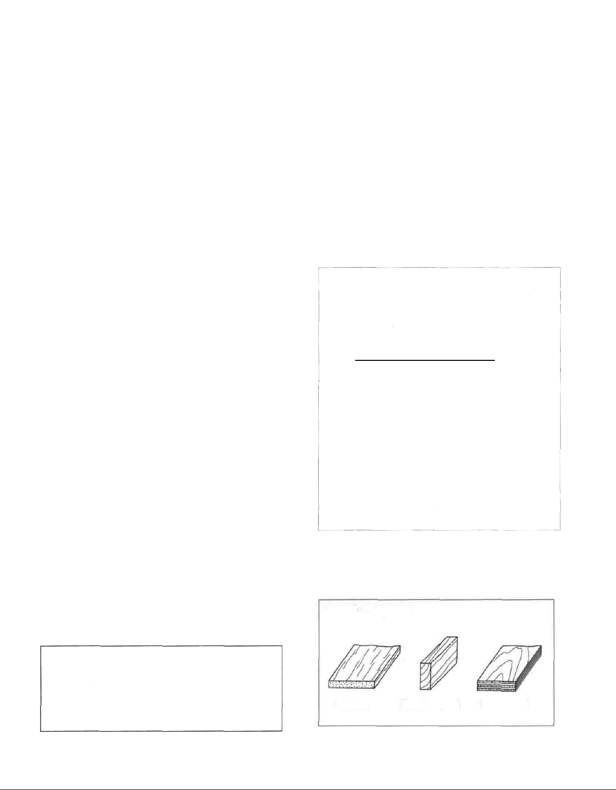
TYPES OF WOOD
3mm
2mm
4mm
Omm
6mm
Remember: Take your time
and follow directions to end up
with a well-built model that is
light, straight and true.
Balsa Basswood Plywood
4
Page 5
DECISIONS YOU MUST MAKE NOW
ENGINE, MOUNT, AND SPINNER SELECTION
The recommended engine size range is as follows:
90 - 1 50 cubic inch displacement 2-cycle
1.20 -1.60 cubic inch displacement 4-cycle
The complete "ENGINE APPLICATION TABLE" is printed on the fuselage plan A portion of that table is
reprinted here to help in your selection of engine, propeller, mount and spinner.
COMPONENTS RECOMMENDED FOR THE ULTRA SPORT 1000:
ENGINE PROP
OS 120 SURPASS SP* 16x8
SUPERTIGRE 2500 16x10
OS 120 SURPASS II 15x8
OS108FSR 15x8
OS 160 TWIN 15x10
* Supercharged version
** "SV" denotes the rubber-cushioned version of this mount, which is recommended.
The above components you select will determine how you build the fuselage, so it is important that
you have these components close at hand while building
MUFFLER SELECTION FOR SUPERTIGRE 2500
ENGINE MOUNT
J-TECJT-120SP(SV)**
J-TECJT-ST125(SV)**
J-TECJT-122(SV)**
J-TECJT-M108(SV)**
Mount incl w/ engine
SPINNER
2-3/4"
3"
2-3/4"
2-3/4"
3"
If you are using the Supertigre 2500 engine, you have two muffler choices One is the standard
SuperTigre "S 3000" silencer that is made for this engine, and which is outlined on the plans If you prefer a
more conventional style muffler, you may choose the J-TEC "JT-3000S" muffler which was custom made as
a result of this project (it is pictured in an Ultra-Sport 1000 on the cover of the April, 1992 issue of R/C
Modeler magazine) Both mufflers work well, but they are very different styles (See the photos on page 43)
LANDING GEAR CONFIGURATION
The Ultra-Sport 1000 may be built with a
"taildragger" or "tricycle" landing gear
configuration, and a retractable main gear may be
installed if you want to really "clean up' this airplane
for ultra-smooth and precise aerobatics.
The Ultra-Sport 1000 was not designed to
accommodate a nose gear retract, therefore if you
want retracts, you'll have to use the "taildragger"
configuration
You have a few choices regarding retracts,
and you should read the following before selecting
the retracts to be used in your plane.
1. The retracts shown in this book are B&D 90degree 2-gear mains These units are
mechanical and are supplied with 5/32" wire
struts which are not considered strong enough
for this airplane, therefore, this kit includes
3/16" wire struts which you may install in the
B&D retract units by drilling them out Although
this system has worked reliably for us. we have
experienced breakage in a couple of instances
involving moderately hard landings
2. The Robart company has indicated that the
following pneumatic retract system will work for
airplanes up to 12 lbs using stock wire struts,
but that the Robostruts should be used for
planes over 12 lbs Listed here are the Robart
items needed for the complete system #606
Retracts, #650 Robostruts, #188 Air control kit,
#190 Quick disconnects, #189 Airline
restricters, #164G Pump w/ gauge, #170 Air
line retainers
3. At the date of this writing, Robart has also
indicated that they will have new heavy-duty
mechanical retracts with 3/16" wire struts
available for this airplane These retracts,
although not tested in the US1000, may be
ideal for this airplane you may want to check
with your hobby dealer regarding the availability
of these retracts.
5
Page 6

OTHER ITEMS REQUIRED
SUPPLIES AND TOOLS NEEDED
Four-channel radio with 6 servos (additional channel
and retract servo required if retracts are being used).
An 800 to 1200 mAh receiver battery is
recommended (IMAA requires 1000 mAh)
• 2 - Servo wire "Y"-harnesses.
• 2 - Servo wire extensions.
•18-Hinges*
• Propellers (Top Flite" Power Point" recommended see engine instructions and above table).
• Spinner - 2-3/4" or 3" diameter (see above table)
• Fuel Tank (12 to 16 ounce)
• Main Wheels - 2 (3" dia. for fixed gear, 2-3/4" for
retracts)
• Nose Wheel -1 (3" diameter, required for trike only)
• Tail Wheel -1 (1" diameter, required for taildragger
only)
• 3/16" Wheel Collars - 4 or 6
• 3/32" Wheel Collars - 2 (required for taildragger
only)
• 3 oz. Thin Bullet CA Adhesive
• 3 oz. Medium or Thick Bullet CA Adhesive
• 2.5 oz. 30-Minute Bullet Epoxy
• Hand or Electric Drill
• Drill Bits: 1/16", 5/64", 3/32", 7/64", 1/8", 9/64",
5/32", 3/16" (Long), 13/64", 1/4", and 5/16"
• Hobby Saw (X-acto Razor Saw)
• X-acto Knife, #11 Blades
• Pliers
• Screw Drivers
• T-Pins
• Straightedge
• Masking Tape
• Sandpaper (coarse, medium, fine grit)*
• T-Bar Sanding Block, or similar
• Waxed Paper
• Iron-on Covering Material (Top Flite MonoKote®
recommended)
• Silicone Fuel Tubing
• Wing Seating Tape (or silicone sealer . . . see
page 50)
• Latex Foam Rubber Padding (1/4" thick)
• Dubro "E-Z Connectors" (or equivalent) - 2
• Plastic Pilot (Williams Bros. 1/4-scale)
*NOTE: There are many types of good hinges on
the market, and everyone has their personal
preferences, therefore, hinges have not been
included in this kit. The current favorite for many
modelers is the type of laminated hinge that permits
hinge slotting with an X-acto knife, and gluing with
thin CA adhesive If you are building a taildragger,
heavy-duty hinges are recommended for the rudder.
See the IMAA Safety Guidelines, a portion of which is
printed in the Appendix at the end of this book.
• Lightweight Balsa Filler
• 1/4-20 Tap, Tap Wrench
• Vaseline Petroleum Jelly
• Sealing Iron
• Heat Gun
• IsopropyI Rubbing Alcohol (70%)
• 3M "77" Spray Adhesive (optional)
• Dremel Moto Tool or similar (optional)
*NOTE: On our workbench, we have four 11" T-Bar
sanders, equipped with #50, #80, #100 and #150-grit
sandpaper This setup is all that is required for
almost any sanding task.
6
Page 7
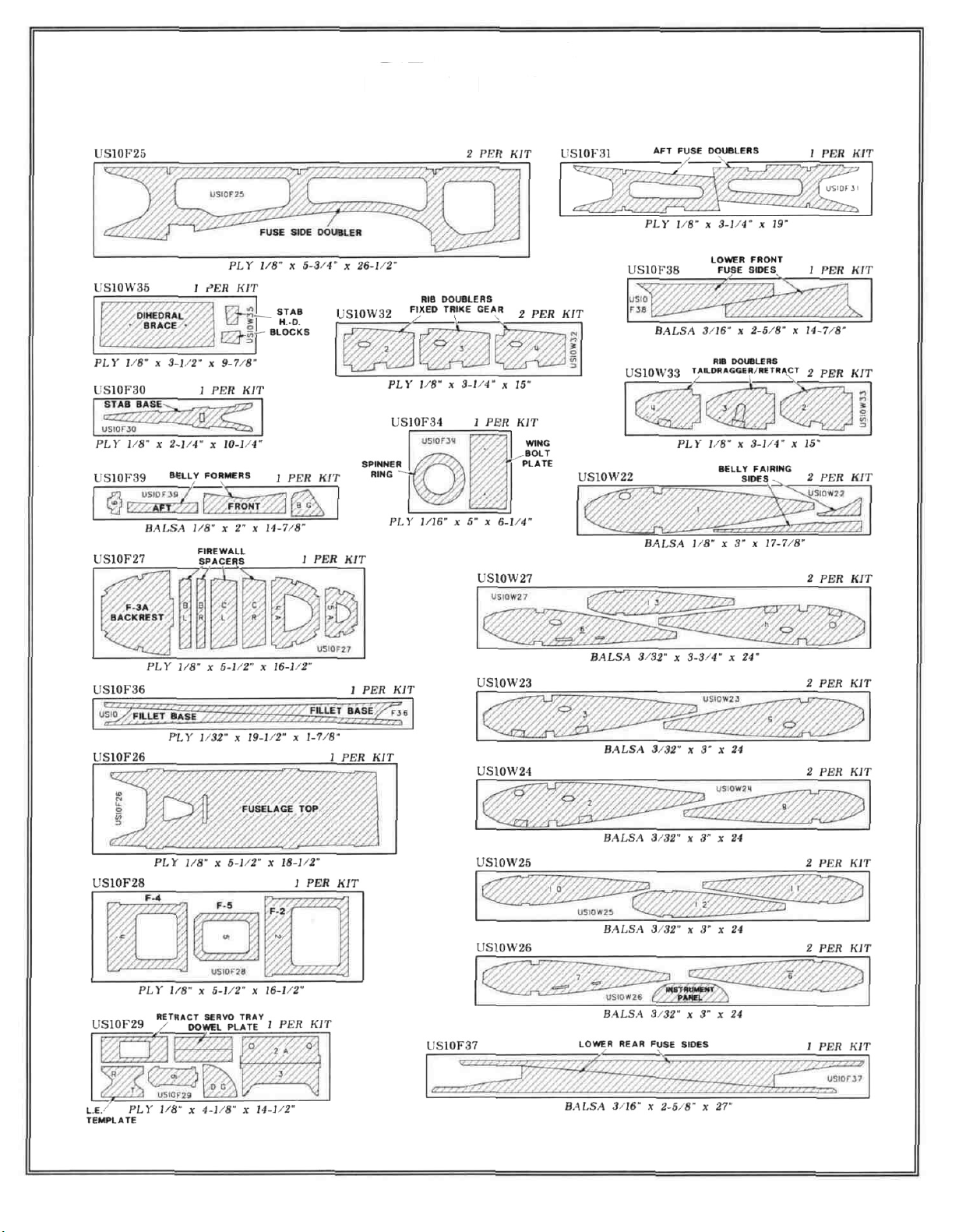
DIE PATTERNS
Use This Drawing To Identify Die-Cut Parts
7
Page 8
GET READY TO BUILD
D 1. Unroll the plan sheets Re-roll them inside out
to make them lie flat NOTE You may cut the
fuselage plan into two sections for ease of building on
the "Bottom View" You may also cut the wing plan
into three sections by cutting along the "cut lines."
D 2 Remove all parts from the box As you do,
figure out the name of each part by comparing it with
the plans and the parts list (see separate sheet).
Using a soft pencil or a felt tip pen, write the part
name or size on each piece to avoid confusion later
Use the die-cut patterns on page 7 to identify the die-
cut parts and mark them before punching out Save
all scraps If any of the die-cut parts are difficult to
punch out, do not force them' Instead, first cut around
the parts with an X-acto knife After punching out the
die-cut parts, use your T-Bar or sanding block to
lightly sand the edges to square them up and remove
any die-cutting irregularities
D 3 As you identify and mark the parts, separate
them into groups, such as fuse, wing, fin and stab,
and hardware.
9" stick, cut the rudder bottom, and glue on the 1/4" x
1/4" x 3-1/2" balsa rudder top Cut two gussets from
the remaining 1/4" x 1" balsa for the inside corners of
the rudder Working right on the plan, pin these parts
in place and glue them together to make the rudder
framework.
D 3 From the 1/8" x 1/4" x 30" sticks, cut the internal
rudder "ribs" (trussing) to fit between the rudder
framework, and glue them in place NOTE: It is not
necessary to get these braces in the exact position
shown on the plan.
TAIL FEATHERS
PARTS NEEDED TO BUILD THE FIN AND RUDDER:
D (1) US10S01 1/4" x 1" x 9" Balsa Rudder Bottom, etc.
D (1) US10S02 1/4" x 1/2" x 9" Balsa Rudder TE
D (1) US10S03 1/4" x 3/4" x 20" Balsa Fin TE, Rudder LE
D (1) US10S04 1/4" x 1/4" x 3-1/2" Balsa Rudder Top
D (1) US10S05 3/8" x 1-1/2" x 10-1/2" Balsa Fin LE
D (1) US10S20 3/8" x 1" x 7" Balsa Fin Top
D (2) US10S06 1/4" x 3-1/4" x 1-1/2" Balsa Fin Bottom
D (2) US10S08 1/8" x 1/4" x 30" Balsa Fin & Rudder
"Ribs"
D (3) US10S17 1/16" x 3" x 30" Balsa Stab/Fin Sheeting
D (1) WBNT128 3/32" wire Tailgear Assembly
BUILD THE RUDDER
D 1 Tape the fuselage plan (side view) down to
your flat work surface Tape a piece of waxed paper
over the fin and rudder portion of the plan
D 2. Using a razor saw, cut a piece of 1/4" x 3/4"
balsa (from the 20" stick) to make the rudder leading
edge Trim the ends of the 1/4" x 1/2" x 9" balsa stick
to make the rudder trailing edge From the 1/4" x 1" x
D 4 Examine the rudder framework and add thick CA
glue to any open joints, then, use your T-bar with
medium grit sandpaper to sand both sides of the
rudder framework smooth.
D 5. Cut and sand the outside perimeter of the rudder
framework to match the plan.
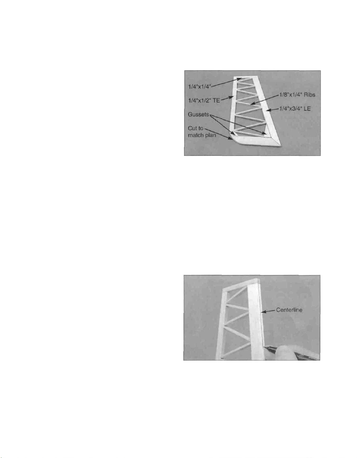
D 6 Carefully draw a centerline all around the edges
of the rudder (this will help to maintain symmetry when
sanding)
D 7 Using a sanding block and coarse (50 or 80-grit)
sandpaper, sand both sides of the rudder to a taper
as shown on the plans The trailing edge should end
up approximately 1/16" wide
8
Page 9
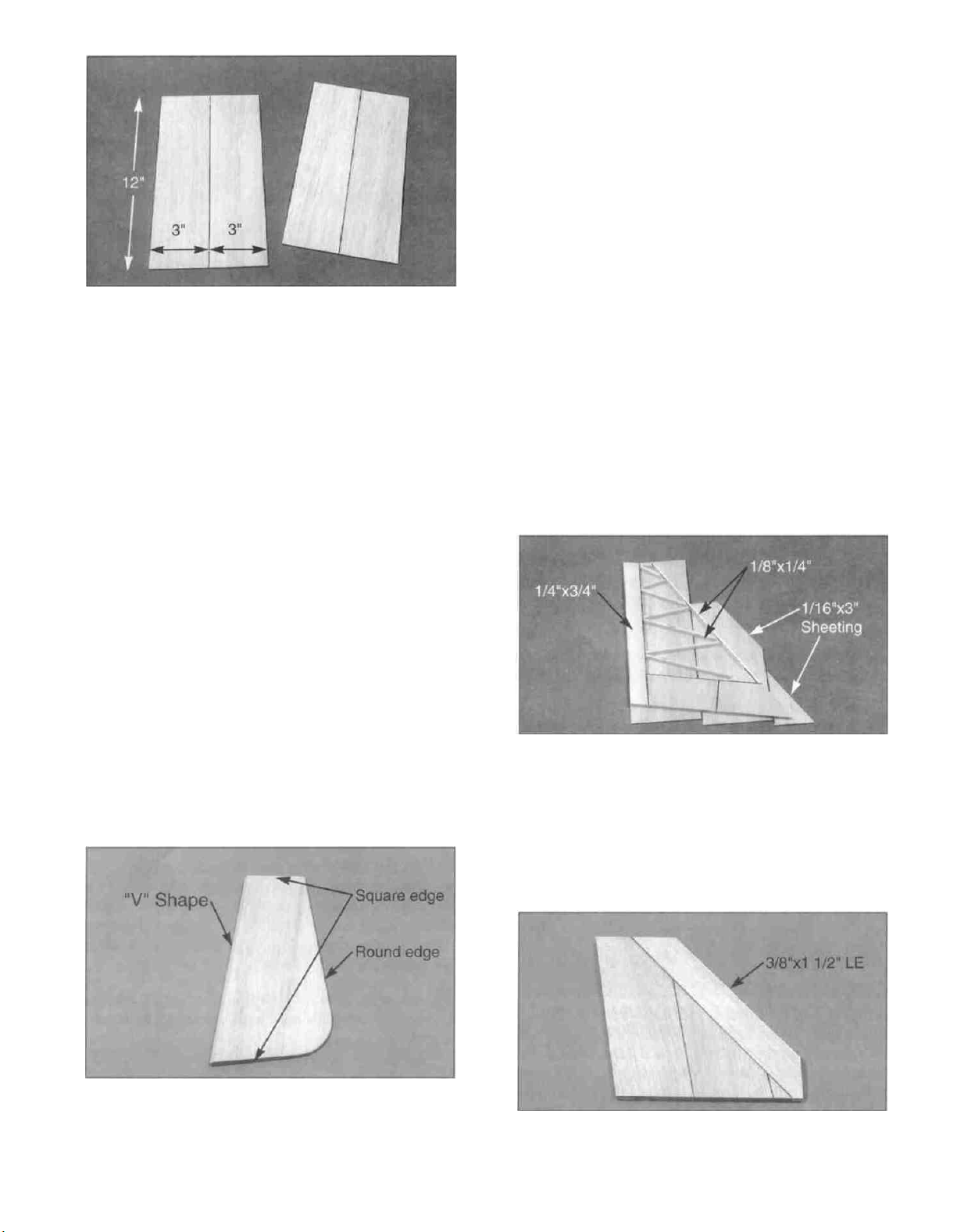
D 8 From the 1/16" x 3" x 30" balsa sheets, cut four
12" lengths Edge glue these sheets together in pairs
to make two 6" x 12" sheets, and sand both sides
smooth with a sanding block
D 9 Lay the rudder framework on the sheeting, mark
the outline, and trim the sheeting to the approximate
outline Leave the sheeting slightly oversize to allow
for positioning.
BUILD THE FIN
NOTE: You will construct the fin framework and add
the 1/16" balsa sheeting, then, you will add the 3/8"
balsa leading edge and fin top.
D 1. Cut the remaining 1/4" x 3/4" balsa stick to make
the fin trailing edge.
D 2 Edge glue the two 1/4" x 3-1/4" x 1-1/2" balsa
blocks together to make the 6-1/2" x 1-1/2" fin
bottom Cut off the ends of this sheet to match the
plan Pin the fin bottom and trailing edge to the plan.
D 3. Complete the fin framework by cutting and fitting
pieces of 1/8" x 1/4" balsa, as shown on the plan.
Glue this assembly together.
D 4 From the remaining 1/4" x 1" balsa stock, cut a
gusset to fit in the lower front corner of the fin Glue in
place
IMPORTANT NOTE: It is essential to get a very
good glue bond between the rudder framework and
the sheeting
D 10. Securely glue the 1/16" balsa sheeting to one
side of the rudder framework
D 11. Trim and sand the edges of the sheeting flush
with the perimeter of the stab framework.
D 12 Repeat steps 10 and 11, sheeting the other
side of the rudder.
D 5. Remove the fin framework from the building
board, sand both sides smooth, and sheet both sides
of the fin with 1/16" balsa in the same manner as the
rudder The fin can be sheeted using only one of the
1/16" x 3" x 30" balsa sheets
D 6. Glue the 3/8" x 1-1/2" x 10-1/2" balsa fin leading
edge to the front edge of the built-up fin.
D 13 Sand the leading edge of the rudder to a "V-
shape" and sand the trailing edge to a rounded shape
(see the rudder cross-section on the plan) Leave the
top and bottom edges square.
D 7 Trim off the top and bottom of the leading edge
to match the plan Sand both sides of the fin smooth
9
Page 10
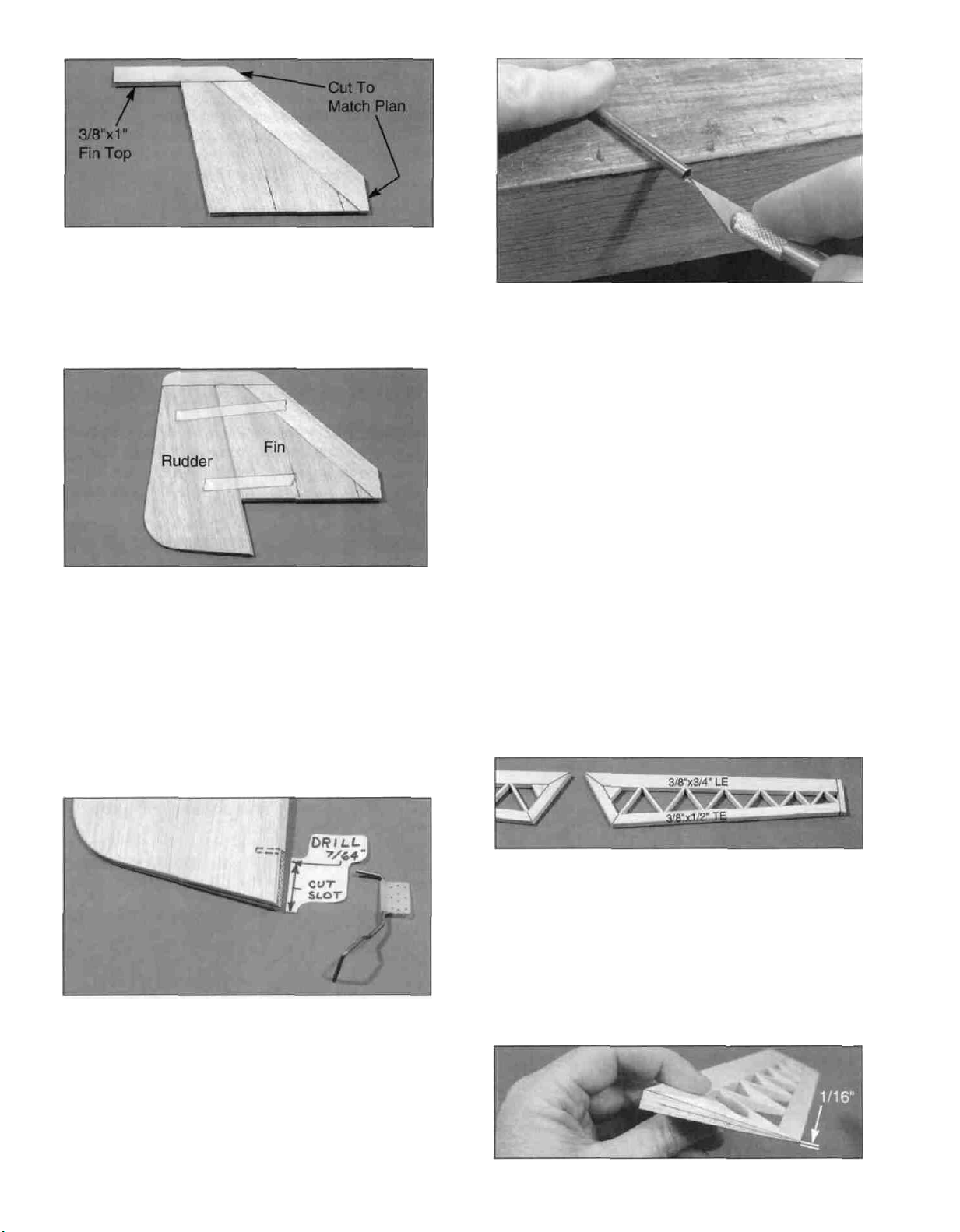
D 8. Glue the 3/8" x 1" x 7" balsa fin top to the top
edge of the fin assembly. Trim and sand the front end
of this piece to match the plan.
D 9. Temporarily tape the rudder to the fin. While
holding the rudder in the neutral position, sand the
3/8" x 1" fin top to match the rudder.
D 10. Draw a centerline on the fin leading edge and
fin top, which will help you maintain symmetry while
sanding.
HINT: Using an X-acto knife, sharpen the inside of
one end of a 1/8" diameter brass tube, and use it to
cut the groove in the leading edge of the rudder.
PARTS NEEDED TO BUILD THE ELEVATORS AND
STABILIZER:
D
(1)
US10S14
D
(1)
US10S15
D
(2)
US10S12
D
(1)
US10S13
D
(1)
US10S11
D
(4)
US10S16
D (2) US10S09 1/2" x 2" x 14-7/8" Balsa Stab LE
D (2) US10S10 1/2" x 1" x 6-1/4" Balsa Stab Tips
D
(6)
US10S17
D (1)US10S21 1/32" x 1-1/4" x 11-1/2" Ply Spar
Thickener
BUILD THE ELEVATORS
3/8" x 2-3/4" x 5" Balsa Stab Center
3/8" Shaped Plywood Stab "Spar"
3/8" x 3/4" x 26-3/4"
LE
3/8" x 1/2" x 30" Balsa Elev TE
1/4" x 3/8" x 4" Balsa
1/8" x 3/8" x 30" Balsa Stab "Ribs"
1/16" x 3" x 30" Balsa Stab/Fin
Balsa
Elev
Stab
End
Sheeting
TE, Elev
D 11. Using a sanding block, sand the fin leading
edge to the approximate shape as shown in the fin
cross-section on the plan. Sand the fin top to a
rounded shape.
D 12. If you are building your Ultra-Sport 1000 as a
"taildragger," check the plans and mark the location of
the tailgear on the rudder. Drill a 7/64" hole in the
rudder (the hole is drilled slightly oversize to allow for
positioning, and to create a hard epoxy "sleeve"
around the wire). Then groove the rudder leading
edge to accept the tailgear wire and the nylon
tailgear bearing.
D 1. Tape the stabilizer plan (side view) down to
your flat work surface, and cover with waxed paper.
D 2. In the same manner as the rudder (steps 1 - 5),
build the framework of both elevators. Cut one of the
3/8" x 3/4" x 26-3/4" balsa sticks to make the leading
edges. Use the 3/8" x 1/2" x 30" balsa stick for the
trailing edges. Cut up the 1/8" x 3/8" x 30" sticks as
needed for the "ribs" (trussing).
D 3. Carefully draw a centerline all around the edges
of the elevators (this will help to maintain symmetry
when sanding).
10
Page 11
D 4 Using a sanding block and coarse (50 or 80-grit)
sandpaper, sand both sides of the elevators to a taper
as shown on the plans. The trailing edge should end
up approximately 1/16" wide. (See photo proceeding
page.)
between the stab sheeting and the stab
framework, especially in the center, therefore, we
recommend using 30-minute epoxy when you apply
the final piece of sheeting Spread the epoxy evenly
but sparingly, to avoid excess weight
D 5 Select the two softest (lightest) 1/16" x 3" x 30"
balsa sheets, and use them to sheet both sides of the
elevators Make sure you obtain a good glue bond
between the sheeting and the internal structure.
D 6. Sand the leading edge of the elevators to a "V-
shape" as shown on the plan Sand the trailing edge
to a slightly rounded shape Do not round the elevator
ends (leave them square)
BUILD THE STABILIZER
NOTE: You will construct the stab framework and
add the 1/16" balsa sheeting, then, you will add the
1/2" balsa leading edges and tips.
D 1 Accurately pin the 3/8" x 3/4" x 26-3/4" balsa
stab TE onto the plan.
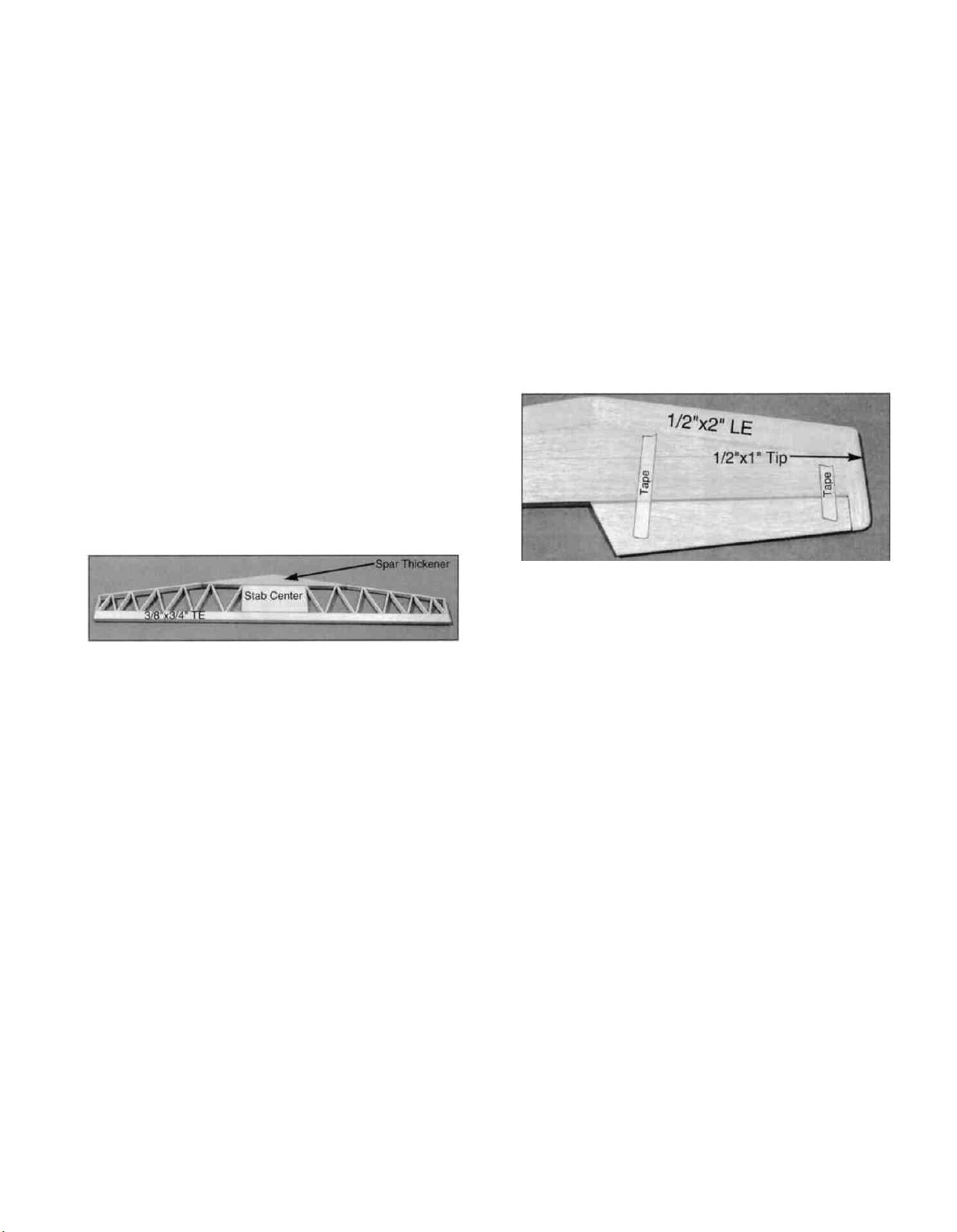
D 6 Cut one end of the two 1/2" x 2" x 14-7/8" balsa
stab leading edges to match the plan at the stab
centerline Glue the leading edges to the stab
framework Cut and sand the ends of the leading
edges to match the ends of the stab.
D 7 Glue the 1/2" x 1" x 6-1/4" balsa stab tips to the
ends of the stab Trim and sand the front ends of the
stab tips to match the plan
D 8 Temporarily tape the elevators to the stab.
While holding the elevators in the neutral position,
sand the 1/2" x 1" stab tips to match the elevator.
D 2 Trial fit the 3/8" x 2-3/4" x 5" balsa stab center
and the triangle-shaped 3/8" ply spar* in place on the
plan. The leading edge of the spar should line up with
the lines on the plan If not, sand the edges of the
balsa stab center until these parts line up correctly
Securely glue the stab center to the stab TE, and glue
the spar to the stab center.
*NOTE: It is common for the 3/8" ply to be slightly
thinner than the 3/8" balsa For this reason, we have
included a 1/32" x 1-1/4" x 11-1/2" ply sheet If the
spar in your kit is thinner than the 3/8" balsa stab
center, glue the 1/32" ply sheet to the spar, and trim
the edges to match the spar.
D 3 Complete the stab framework by cutting and
fitting pieces of 1/8" x 3/8" x 30" balsa, as shown on
the plan. Glue this assembly together.
D 4 Remove the stab framework from the building
board and sand both sides and all edges smooth.
D 5. There are four remaining 1/16" x 3" x 30" balsa
sheets Edge glue these sheets together in pairs to
make two 6" x 30" sheets, and sand both sides
smooth with a sanding block Use these to sheet the
top and bottom of the stab framework NOTE: It is
essential to get a strong and complete bond
D 9 Draw a centerline on the stab leading edge and
tips, which will help to maintain symmetry while
sanding.
D 10. Using a sanding block, sand the stab leading
edge to the approximate shape as shown in the stab
cross-section on the plan Sand the stab tips to a
rounded shape.
TEMPORARILY INSTALL HINGES
D 1 Using the plans as a guide, mark the hinge
locations on the stab, elevators, fin and rudder.
NOTE: There are many types of good hinges on the
market, and everyone has their personal preferences,
therefore, hinges have not been included in this kit.
The current favorite for many modelers is the type of
laminated hinge that permits hinge slotting with an
X-acto knife, and gluing with thin CA adhesive If you
are building a taildragger, heavy-duty hinges are
recommended for the rudder See the IMAA Safety
Guidelines in the Appendix at the end of this book.
11
Page 12
CAUTION!!!: You must use extreme care when
cutting hinge slots with an X-acto knife, to avoid
cutting yourself! If the balsa part breaks while
you are pushing on the knife, the blade could go
into your hand before you know it! A good pre
caution is to wear leather gloves while performing
this step.
D 2. Cut the hinge slots and temporarily install the
elevator and rudder hinges.
WING ASSEMBLY
PARTS NEEDED TO BUILD THE WING:
D (4) US10W07 1/8"x1/2"x39-1/8" Basswood Long Spar
D (4) US10W08 1/8"x1/2"x26" Basswood Medium Spar
D (4)US10W09 1/8"x1/2"x13-13/16" Basswood Short
Spar
D
(1)
US10W02
D
(1)
US10W14
D (2) US10W01 15/32"x1-1/2"x40" Tapered Balsa Aileron
D (4) US1 OW03 3/32"x2"x39-3/8" Balsa TE Sheeting
D (4) US10W04 3/32 x3"x39-1/8" Balsa LE Sheeting
D (2) US10W05 3/32"x1-3/4"x24-1/2" Balsa Front LE
D (4) US10W06 1/8"x1/2"x3-1/4" Ply Aileron Servo Rail
D (12) US10W10 3/32"x3"x11-1/8" Balsa Center Sheeting
D (1) US10W20 3/32"x3'x18" Balsa Aileron Bay Sheeting
D (2) US10W21 1-1/4"x1-7/8"x11-5/8" Balsa Wing Tip
D (1) US10W12 1/4"x39-1/8" Tapered Balsa TE Support
D
(2)
US10W15
D (2) US10W22 Die-cut 1/8" Balsa Rib 1, etc.
D
(2)
US10W27
D
(2)
US10W23
D
(2)
US10W24
D (2) US10W25 Die-cut 3/32" Balsa Ribs 10, 11 & 12
D
(2)
US10W26
D (1) US10W35 Die-cut 1/8" Ply Dihedral Brace
D (1) US10F29 Die-cut 1/8" Ply Dihedral Gauge, etc.
D (1) US10F34 Die-cut 1/16" Ply Bolt Plate, etc.
D (1) GLTP014 4" x 36" Fiberglass Cloth
D (6) SS90W11 3/32" x 3/8" x 36" Balsa Cap Strips
D (2) NYLON03 Small nylon Control Horn
D (10) SCRW002 2-56 x 5/8" Machine Screw
Shaped Balsa LE
3/32"
Sheet
Jig
5/16"
Die-cut 3/32" Balsa Ribs 4, 6 &
Die-cut
Die-cut 3/32" Balsa Ribs 2 & 8
Die-cut 3/32" Balsa Ribs 7 &
x3"
x2-5/8"
Dia. x 6" Birch Wing
3/32"
and
TE
Set
Balsa Shear Webs (22)
Dowel
Balsa Ribs 3 & 5
13
9, etc.
D (2) WBNT170 3/16" wire Main LG Struts
(PARTS NEEDED FOR OPTIONAL RETRACTABLE
LANDING GEAR)
D (2) US10W16 1/4"x1-5/16"x3-5/16" Ply Rear Mtng. Plate
D (2) US10W17 1/4"x3-5/16" Tapered Ply Front Mtng.
Plate
D
(2)
US10W33
D (1) WBNT171 3/16" wire Left Retract Strut
D (1) WBNT172 3/16" wire Right Retract Strut
D (2) Pushrod wires w/ 2-56 threads one end (NOT INC )
D (2) 2-56 steel clevises (NOT INCLUDED)
Die-cut
ger)
1/8"
Ply Rib Doublers (taildrag
PREPARE WING PARTS
Before assembling the wing, there are several
preliminary assemblies that must be made . ..
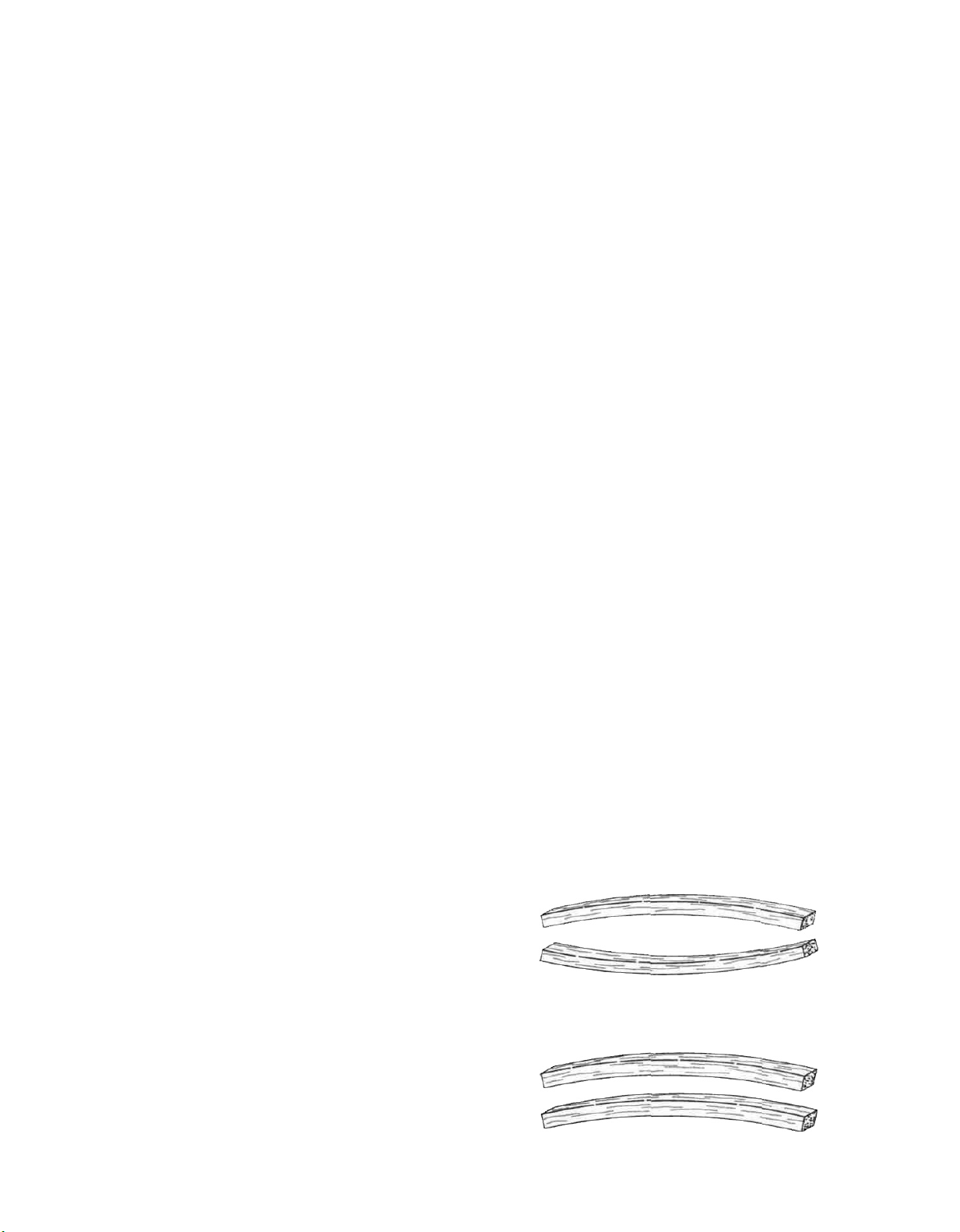
D 1. Before using the hard balsa spars, examine
them carefully for possible imperfections Look for
knots, soft spots, diagonal grain and any other
imperfections If possible, position each spar so the
imperfections (if any) are on the outer half of the wing
panel (toward the tip), where they will be least affected
by high stress If the spars are warped slightly, try to
"balance them out" by installing the warped spars in
opposite directions (see sketch) NOTICE: If you feel
that any of the wing parts are unusable due to severe
warps or other defects, give us a call and we'll replace
the parts.
Two Warped Spars Installed This Way Will
Result In A Straight Wing
(ADDITIONAL PARTS NEEDED FOR FIXED
LANDING GEAR)
D (2) SS90W18 1/2"x3/4"x7-3/4" Basswood Main LG
Block
D (2) US10W13 1/2"x3/4"x 1-1/2" Maple Short LG Block
D (2) SS90W20 1/2"x3/4"x1/2" Maple LG Reinf. Block
D (2) US1 OW33 Die-cut 1/8" Ply Rib Doublers (taildrag
ger)
D (2) US10W32 Die-cut 1/8" Ply Rib Doublers (tnke gear)
Two Warped Spars Installed This Way Will
Result In A Warped Wing
12
Page 13
D 2 Sand one end of each of the medium and short
spars to a 2-1/2" taper as shown in the "Wing Spar
Detail" on the plan
RIB DOUBLERS (Fixed Landing Gear -
TAILDRAGGER)
(Skip this section of you will be installing retracts)
D 3. Glue the medium spars to the long spars, and
glue the short spars to the medium spars, as shown
in the "Wing Spar Detail." Sand the edges of the
spars to remove any excess glue and to make the
edges uniform. Make four spar assemblies.
RIBS
D 1. Carefully punch out all the die-cut balsa wing
ribs. Sand the edges slightly to remove any die-
cutting irregularities.
D 2. Note that the wing plan shows two alternate
locations for the main landing gear blocks Note also
that Ribs W-2, W-3 and W-4 have partial cutouts for
each of the two locations If you are building your
plane as a fixed gear taildragger, cut out the front
notches in these ribs If you are building your plane
with a tricycle gear, cut out the rear notches (If you
will be installing retracts, do not cut out any of the
notches).
RIB DOUBLERS (Fixed Landing Gear - TRIKE)
(Skip this section if your airplane is to be a taildragger)
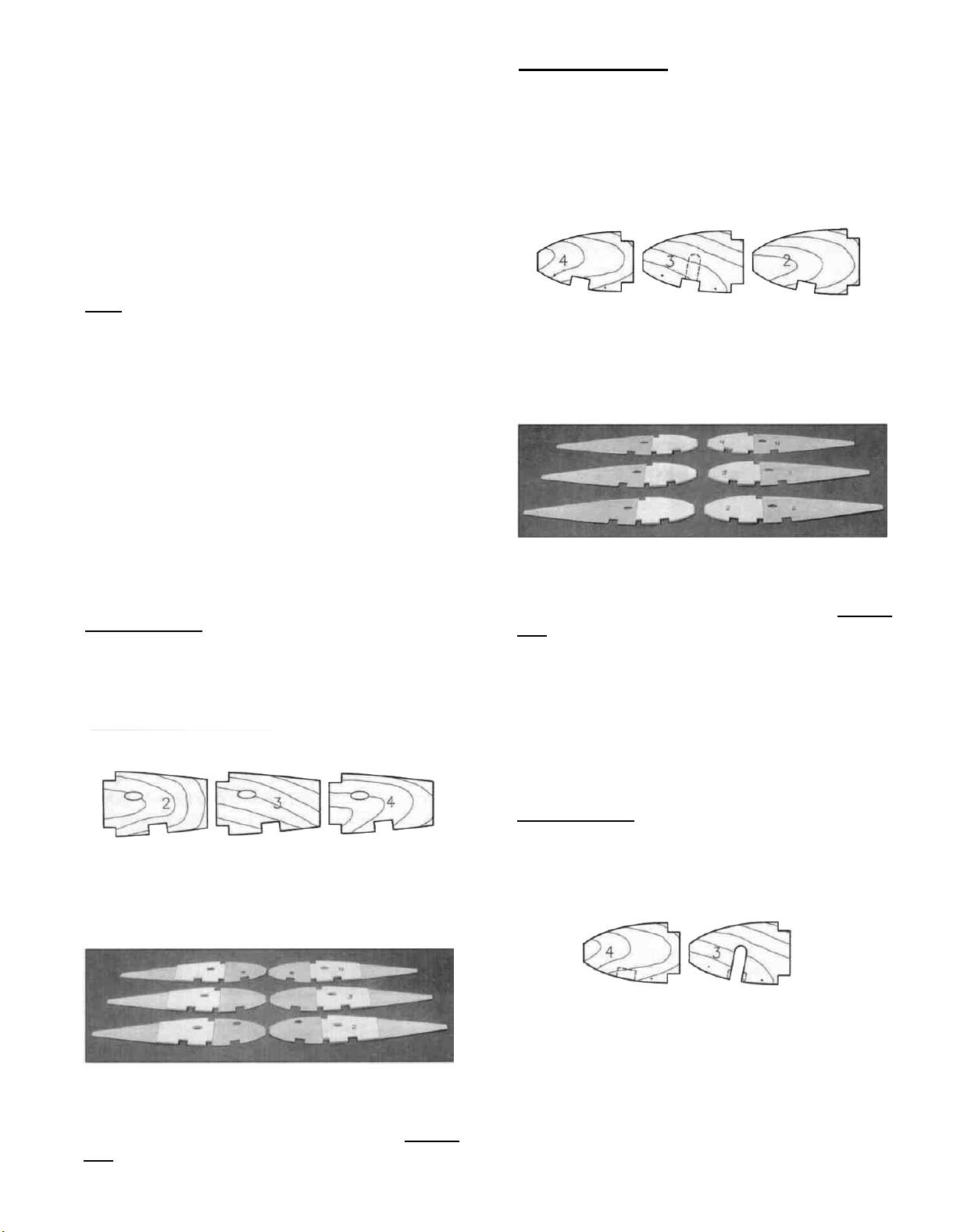
D 1. Identify the die-cut 1/8" ply landing gear
doublers for fixed trike gear, using the following
sketch:
D 1 Identify the die-cut 1/8" ply landing gear
doublers for fixed taildragger, using the following
sketch:
D 2. The doubler for rib W-2 has a notch cut out for
the landing gear block The doublers for ribs W-3 and
W-4 have the notch locations marked, and you must
now cut out these notches.
Do not cut out aft rib notches as shown in photo.
D 3 Glue these die-cut 1/8" ply landing gear doublers
to ribs W-2, W-3 and W-4 NOTE: Make a RIGHT
and a LEFT set, gluing the doublers to the inboard
side of the ribs. Take care to carefully align the
doublers with the spar notches The doublers are
slightly shorter than the ribs at the front edge, to allow
fitting into the leading edge notches.
Do not cut out front rib notches as shown in photo.
D 2. Glue these die-cut 1/8" ply landing gear doublers
to ribs W-2, W-3 and W-4. NOTE: Make a RIGHT
and a LEFT set, gluing the doublers to the inboard
side of the ribs.
RIB DOUBLERS (Optional Retractable Landing Gear)
D 1. Identify the die-cut 1/8" ply landing gear
doublers for retracts, using the following sketch:
D 2. Note that these doublers have two small punch
marks. Push a T-pin through these marks so the
location is visible on both sides Now draw a line from
the front edge of each doubler to the back edge, using
the two small holes for alignment Draw the lines on
both sides These lines will later be used for
alignment of the retract mounting plates.
13
Page 14
D 3 The doubler for rib W-3 is marked for a long,
narrow notch Extend the lines of this notch to the
edge of the doubler, and cut out this notch
D 4 Glue these die-cut 1/8" ply landing gear doublers
to ribs W-3 and W-4 NOTE: Make a RIGHT and a
LEFT set, gluing the doublers to the inboard side
of the ribs. Take care to carefully align the doublers
with the spar notches The doublers are slightly
shorter than the ribs at the front edge, to allow fitting
the ribs into the leading edge notches
D 5 Cut out the long slot in the W-3 ribs using the
slot in the doublers as a guide
D 6 If you will be installing B&D retracts, drill a 3/8"
hole in the #4 doublers, using the punched hole in the
W-4 ribs as a guide.
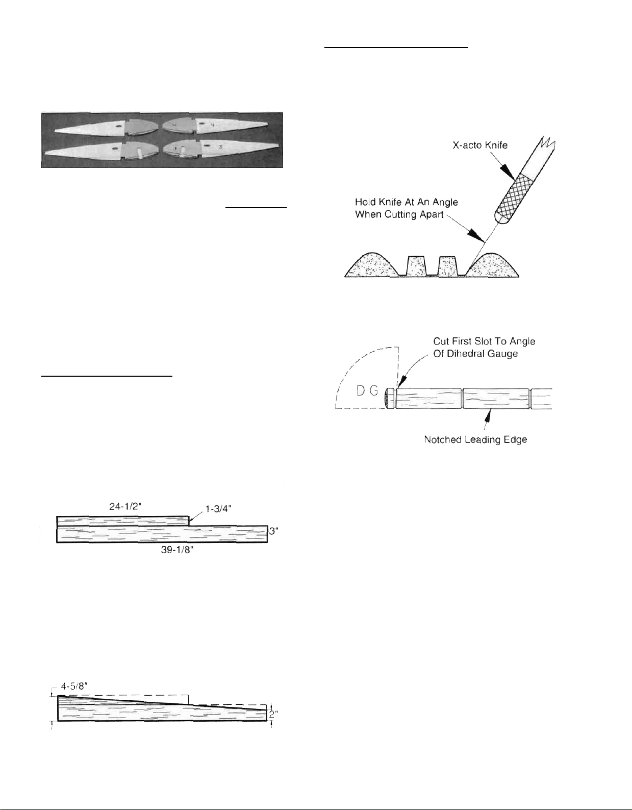
LEADING & TRAILING EDGES
D 1 The shaped and notched wing leading edges
(LE) and trailing edges (TE) are fastened together by
thin strips of balsa Separate them by cutting with an
X-acto knife, as shown in the following sketch.
LEADING EDGE SHEETING
D 1. Prepare the leading edge sheeting as follows
Edge glue the 3/32" x 1-3/4" x 24-1/2" balsa sheets to
the 3/32" x 3" x 39-1/8" balsa sheets as shown here,
making four sets. NOTE: The two smaller front
sheets will be cut on a diagonal in the next step,
providing you with the front pieces you will need to
complete the 3rd and 4th sets
D 2. Now measure and mark the balsa sheeting (see
sketch below), then cut the angle in the sheeting,
cutting along a metal straightedge for accuracy
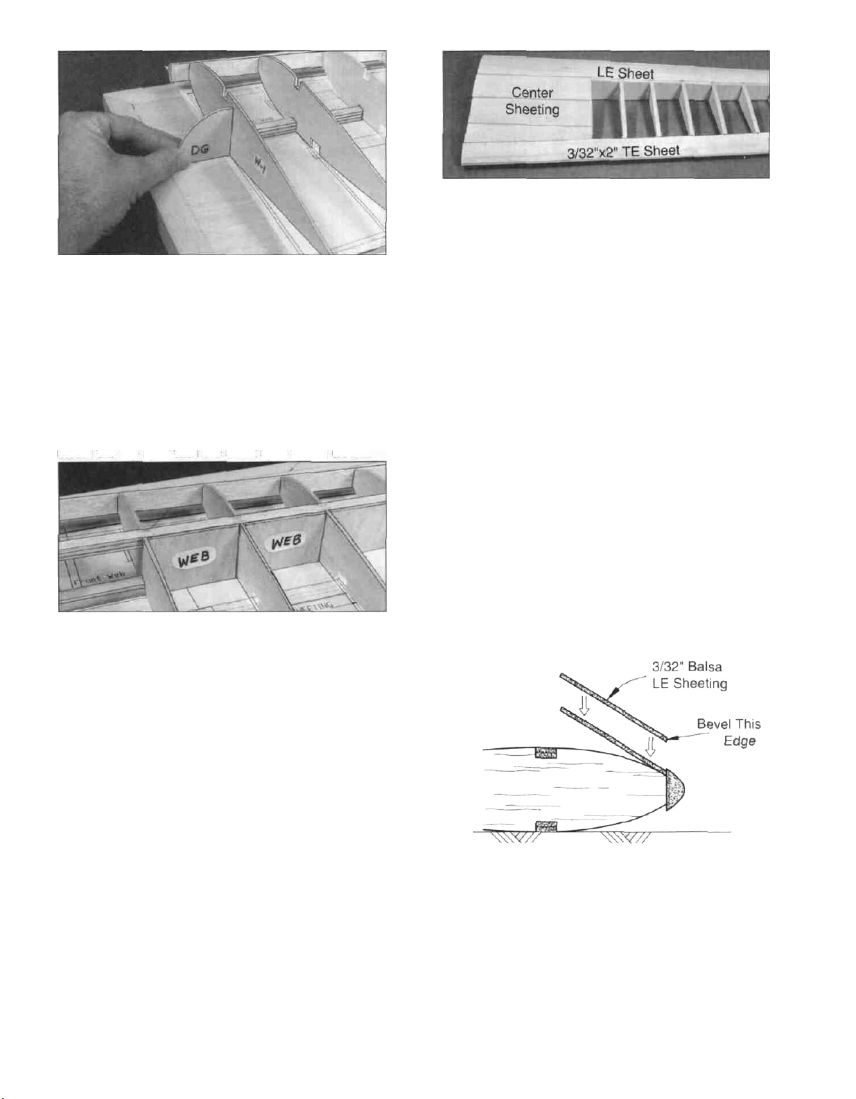
D 2 Examine the shaped, notched leading and
trailing edges Notice that the notches at one end of
each LE and TE are 3-1/2" apart These are the
notches for W-1 and W-2 Also notice that all notches
in the LE and TE are vertical, however, rib W-1 will be
installed at a slight angle using the Dihedral Gauge
Therefore, you should now modify the notch for W-1
by cutting it to the angle of the rib You may
determine the approximate angle of the cut by holding
the Dihedral Gauge (DG) against the LE as shown
above.
BUILD THE WING PANELS
NOTE: It will be helpful to build the wing on a piece
of "Celotex" or other semi-soft (and flat) surface, into
which you may easily stick pins to firmly hold down the
wing parts while building, to avoid warps
D 1 Tape the plan to your flat work surface, and
cover the wing drawing with waxed paper (so you
won't glue the wing to the plan') NOTE: If your work
14
Page 15
space is limited, you may cut the left and right wing
half drawings apart
NOTE: Follow steps 2 through 45 to build the
RIGHT wing panel, then repeat these steps to
build the LEFT wing panel.
D D 2 Pin one of the spars to the plan with the
short spar facing up and toward the root. NOTE:
The spars are cut slightly too long Center the spar on
the plan so an equal amount protrudes on both ends.
with the aft edge of the TE (see sketch below) You
may cover the top edge of the Jig with a strip of waxed
paper or plastic wrap to avoid gluing it to the TE
D D 3 Place the ribs on the spar in their
approximate position, but do not glue IMPORTANT:
Pay special attention to the way ribs W-1 through W-7
are installed ..
W-1: Oval-shaped retract pushrod hole up.
W-2: LG slots down, LG doubler (if any)
towards tip
W-3: LG slots down, LG doubler towards tip
W-4: LG slots down, LG doubler towards root.
W-5: Oval-shaped aileron servo wire hole up
W-6: Aileron servo rail slots down
W-7: Aileron servo rail slots down
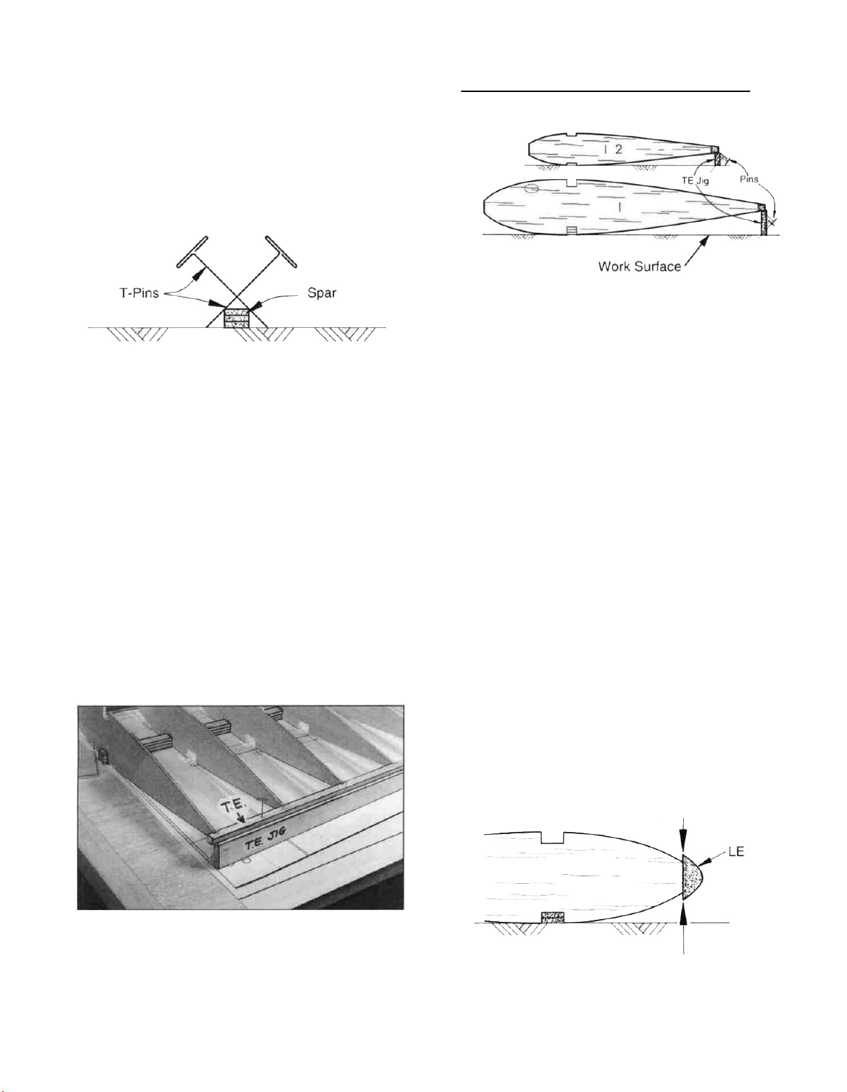
D D 5 Pin the TE to the TE Jig, making sure the ribs
line up with the plan
D D 6 Glue ribs W-2 through W-13 to the TE
(Apply glue sparingly, to avoid gluing the TE to the
Jig) Glue ribs W-2, W-6 and W-13 to the spar,
making sure they are lined up with the plan, and
positioned at 90-degrees to the work surface
D D 7 Work the notched leading edge onto the
front ends of the ribs NOTE: Position the LE as
shown here
Center LE Vertically On Front Of Ribs
This photo is not 100% accurate Some components
may vary
D D 4 Insert the rear ends of the ribs into the
notches in the TE, then block up the TE with the 1/4"
balsa TE Jig supplied NOTE: THE NARROW END
OF THE TE JIG IS AT RIB W-13. Securely pin the jig
to the building surface, with the aft edge of the Jig even
15
Page 16
This photo is not 100% accurate. Some components
may vary.
D D 8. Make sure the ribs are fully down on the plan
and all ribs are inserted into the LE notches. Angle rib
W-1 slightly using the dihedral gauge (DG). Glue W-
1 to the TE, LE and bottom spar. Glue all other ribs to
the LE and bottom spar. Follow up by applying a drop
or two of medium or thick CA to all spar/rib joints.
D D 9. Glue the top spar in place, making sure you
do not change the angle of W-1. IMPORTANT:
Install the top spar with the short spar facing down.
This photo is not 100% accurate. Some components
may vary.
D D 10. Sort through the pre-cut 3/32" balsa vertical
grain shear webs, selecting the hardest ones (which
will be used near the root of the wing). Glue the shear
webs to the rear edge of the spars in all rib bays
except between ribs W-1 and W-2. NOTE: You
may wish to trial fit, mark, and trim each web before
gluing in. NOTE: The webs must be securely glued
to the spars, but it is not necessary to glue the webs
to the ribs.
D D 11. Lightly sand the tops of the ribs to blend with
the notched trailing edge; then glue one of the 3/32" x
2" x 39-3/8" balsa trailing edge sheets in place.
NOTE: The edge of the TE sheet may not be exactly
straight, but just position the sheet so it slightly
overlaps the TE, and any overlap can be sanded off
later.
D D 12. Before applying the leading edge sheeting in
the next step, block up the leading edge in a few
places with scraps of wood. Then use your T-bar to
lightly sand off the edges of the shear webs and
smoothly blend the ribs to the spar. Also, lightly sand
the tops of the ribs to eliminate imperfections.
D D 13. Prepare the 3/32" balsa leading edge
sheeting by sanding the front edge to a slight bevel
so it will fit snugly against the back of the leading
edge.
NOTE: In the next steps, maintain straightness by
keeping the wing down on the flat surface and on
the TE
Jig.
NOTE: It will be helpful to have the following items
handy for the next step . . . thin CA, thick CA, a wet
cloth and masking tape. Read through the following
step and go through a "dry run" before actually gluing.
D D 14. Position the leading edge sheeting at the
rear edge of the notched LE so there is an equal
16
Page 17
amount protruding on both ends of the wing Using
thin CA, glue the front (beveled) edge of the leading
edge sheeting to the back edge of the leading edge.
Now wet the top surface of the sheeting (if necessary)
to make it bend easier Apply thick CA glue to the top
edge of the ribs and to the front half of the spar Then
immediately bend the sheeting down onto the ribs and
spar Hold the sheeting down with long strips of
masking tape until the glue has set.
D D 15 Using the 3/32" x 3" x 11-1/8" balsa sheets,
glue the top center section sheeting in place as
shown on the plan (Use the scraps trimmed from the
LE sheeting if needed for the aft pieces).
D D 16 From the 3/32" x 3/8" x 36" balsa sticks, cut
and glue cap strips to the top edges of all exposed
ribs, from the TE sheeting to the LE sheeting HINT:
For easier positioning of the cap strips, first mark the
location of each rib on the LE and TE sheeting
D D 21 Drill a 3/16" hole down through the grooved
LG block and the 1-1/2" block Line up the drill so you
are drilling straight down through the middle of the 11/2" block.
D D 22 Trial fit the 3/16" diameter main landing
gear wire into the landing gear block at this time Cut
or file the groove and hole in the landing gear block as
necessary for a good fit
D D 17. Remove the wing panel from the building
board Check all glue joints, adding glue as
necessary.
D D 18. Using a razor saw and a sanding block,
carefully cut off and sand all excess sheeting spars,
LE and TE even with W-1 and W-13. Sand the TE
sheeting flush with the TE.
FOR FIXED LANDING GEAR, perform steps 19-22
D D 19 Trial fit the long grooved hardwood LG
block into the notches in ribs W-2, W-3 and W-4 (see
the wing plan for proper positioning) File the notches
if necessary for a good fit. Now use epoxy to securely
glue the block in place.
FOR RETRACTS, perform steps 23 - 31
NOTE: In the Ultra-Sport 1000 prototype we used
B&D mechanical retracts, and you will see them in the
photographs You may use whatever type of retracts
you prefer, as long as they are of the correct size for
this airplane (see the introductory remarks at the
beginning of this book) If you are using B&D retracts,
it will be necessary to drill them out to accept the 3/16"
wire struts supplied in this kit (see below*) It is also
recommended that you file a "flat" on the 3/16" struts
at the set screw location, to prevent the struts from
turning You should wait until the retracts have been
installed before doing so, to insure proper alignment
(See Step 30).
instructions for drilling B&D retracts. Back out the set
screw so it won't interfere with the drill Drill out the
strut hole first with an 11/64" bit, then a 3/16" bit If it
is difficult to insert the strut, re-drill the hole with a #12
(.189") drill bit Stop drilling as soon as you feel the
bit bottom out in the hole. Temporarily install the
gear strut, tighten the setscrew, and check operation.
Due to the larger strut, the setscrew may bind against
the actuator arm and prevent full retraction If this is
the case, you'll have to file a small amount off the top
of the set screw Do this by drilling a 5/32" hole in a
scrap piece of hardwood, screwing the set screw in
with 1/32" protruding, and filing off the top of the set
screw.
D D 20. Epoxy the 1/2" x 3/4" x 1-1/2" hardwood
block to the LG block and to the 1/8" ply doubter on
rib W-2, as shown on the plan and in the photo Then
epoxy the 1/2" x 3/4" x 1/2" hardwood block to the
other end of the LG block and to the 1/8" ply doubler
on rib W-4.
NOTE: Most standard wheels have a 5/32" diameter
axle hole, so you'll have to drill the hubs of your
wheels to fit the 3/16" diameter landing gear wire
supplied in this kit Start by using a 3/16" drill bit, but
because the nylon hub material is somewhat flexible, it
may be necessary to use a 13/64" drill bit to get the
hole large enough to allow the wheel to turn freely.
17
Page 18
NOTE: Install a wheel on the strut and check out how
much force it takes to raise the wheel If you are using
standard (heavy) wheels, it may be necessary to
increase the tension on the retract assist spring If
you are using lighter wheels, such as Sullivan "Skylite"
wheels, the stock spring tension may be adequate
D D 23. You previously drew lines through the
location holes in the doublers on ribs W-3 and W-4.
Now measure down 1/4" from this line (toward the top
sheeting) and make a few marks
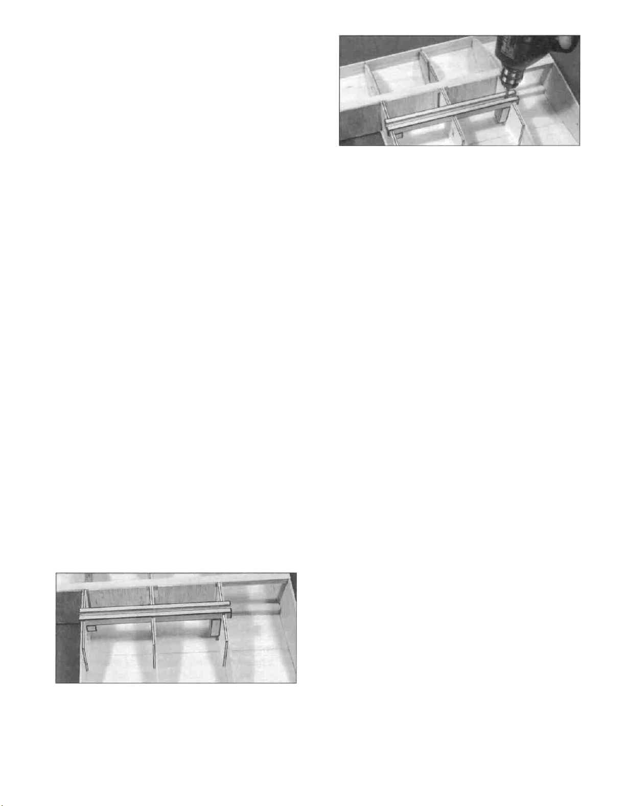
D D 24 Find all the 1/4" balsa triangle in the kit, and
select the hardest balsa for the next step
D D 29 Install the retract mechanism (with the gear
strut but without a wheel) and the pushrod * Cut
clearance holes and notches in the ribs and mounting
plate as required for the strut and pushrod Cycle the
gear a few times to make sure everything clears
*Pushrods for optional retracts not included in kit
D D 30 This is a good time to file a "flat" on the gear
strut A good way to do this is to align the axle with
the spar (or set it to "toe-in" slightly), then tighten the
set screw to mark the strut Remove the strut, and file
a flat area on the strut similar to the stock strut that
came with the retracts Re-install the strut, tighten the
set screw, and check the strut alignment.
D D 25. Cut pieces of 1/4" balsa triangle to run 1/4"
below the lines on the doublers, from the spar to the
LE Glue these triangles to the doublers to serve as
supports for the retract mounting plates Cut away the
section of the triangle that bridges the slot in W-3.
D D 26 Bevel the rear edge of the 1 /4" x 1 -5/16" x 35/16" ply aft retract mounting plate to fit snugly against
the spar Bevel the front edge of the tapered 1/4 ply
retract mounting plate to fit snugly against the LE
D D 31. Remove the strut, but leave the retract
mechanism in the mount Measure exactly where the
strut socket is, and make reference marks on the spar
and LE so that you can later cut into the leading edge
sheeting in the right place to find it after the sheeting
has been installed
WING ASSEMBLY CONTINUES
(for all landing gear options)
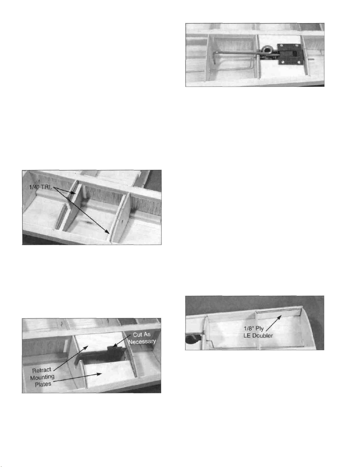
D D 32 Glue one of the die-cut 1/8" ply LE doublers
to the back of the LE, between ribs W-1 and W-2
D D 27 Trial fit your retract mechanism onto the
mounting plates, and cut out notches in the plates as
necessary to clear the mechanism
D D 28 Using 30-minute epoxy, glue the retract
mounting plates securely to the rib doublers, spar and
LE Wipe away any excess epoxy along the LE
D D 33 Place the wing panel upside down on the
building board, turn the TE support jig end for end and
pin the TE to the support jig (again, with the narrow
end of the jig at the wing tip), and place blocks under
the leading edge for additional support
D D 34 Sand the TE to blend with the ribs Sand off
any excess glue or other imperfections on the bottom
of the wing Then install the 3/32" x 2" x 39-3/8"
bottom TE sheeting.
18
Page 19

IMPORTANT NOTE: To insure a straight wing,
you must pin or weight the TE securely down on
the TE jig while the bottom sheeting is glued in
place!
D D 35 Sand a bevel on the front of the LE
sheeting, and glue it in place as previously done on
the top (When bending the sheeting down over the
ribs, use long strips of masking tape to hold the
sheeting down, rather than using heavy downward
pressure with your hands, to avoid introducing warps).
NOTE: If you are using fixed taildragger gear, you
will need to cut a slot in the sheeting to fit around the
main gear block If you are using retracts, you will be
sheeting over the retract mechanism If you have
installed retracts, use your measurements and
reference marks to locate and trim away the sheeting
at the center of the retract unit
DO NOT install the bottom center section sheeting
at this time.
the TE sheeting, and it should extend about 1/8" past
the ribs on each side to simulate cap strips Cut a
hole in this sheeting over the servo rails just big
enough for the servo to pass through, then mount the
servo to the rails NOTE: For most standard servos,
this will result in the top of the servo case being flush
with the sheeting, with only a enough gap in the
sheeting at each end of the servo for servo installation
and access to the mounting screws.
D D 38. From the 3/32" x 3/8" x 36" balsa sticks, cut
and glue cap strips to ribs W-5, W-8, W-9, W-10, W11,W-12andW-13.
DO NOT install the bottom center section sheeting
at this time.
D D 39. Remove the wing panel from the building
board and re-check your glue joints Sand the
sheeting flush with ribs W-1 and W-13. Sand the TE
sheeting flush with the TE.
D D 40 Cut a 3" piece and a 6" piece off the 1-1/2" x
40" tapered balsa aileron stock and glue these pieces
to the tip and root ends respectively (see the wing
plan) IMPORTANT: When gluing these pieces,
make sure they line up equally with the top and bottom
surfaces of the wing Sand these pieces flush with W-
1 and W-13 and to blend smoothly with the wing.
D D 36. Glue the 1/8" x 1/2" x 3-1/4" ply aileron
servo rails into the slots in W-6 and W-7, spacing
them to fit your servo Temporarily mount a servo to
the rails. Make reference marks for the edges of the
servo on the LE and TE sheeting and on ribs W-5 and
W-8 which you will use in the next step Now remove
the servo.
D D 37. Using the 3/32" x 3" x 18" balsa sheet, cut
and glue pieces to the bottom of ribs W-6 and W-7
This sheeting covers the area from the LE sheeting to
D D 41 Glue the 1-1/4" x 1-7/8" x 11-5/8" balsa
wing tip to rib W-13 Then carve and sand it to the
shape shown on the plan. A razor plane and a
sanding block with coarse sandpaper will speed this
task.
19
Page 20

D D 42. The shape of the leading edge is very
important to the performance of the finished
airplane*. Carve and sand the leading edge to match
the template at the root and tip, and taper it smoothly
from one end to the other *NOTE: If you shape the
leading edge to match the die-cut 1/8" ply LE
Template supplied, this will result in a very stable wing
that will resist tip stalling at high angles of attack For
example, it will be forgiving if you happen to flare a
little too much on the landing approach, and recovery
from spins will be instantaneous On the other hand,
this stability may make the airplane somewhat
sluggish when entering snap and spin maneuvers, and
it may require increased elevator and rudder throws
(and possibly an aft CG location) to perform these
maneuvers If your flying style demands crisp snap
and spin capabilities, you may want to sand the
leading edge to a slightly sharper shape (smaller
radius LE)
To avoid tip stalls, make sure the leading edges
of both wing panels have the same shape.
D D 43 Cut the remaining aileron stock to the
correct length and trim the ends to the correct angles
Now sand the leading edge of the aileron to a "V"shape as shown on the plan A razor plane is
especially helpful for rough shaping the aileron leading
edge.
drilling straight down through the aileron (not
perpendicular to the top or bottom surfaces) Harden
the balsa in the area of the control horns (on both
sides of the aileron) by poking several small holes with
a pin, then applying thin CA glue Sand smooth.
Temporarily mount the nylon horn using the 2-56 x
5/8" machine screws and the nylon nutplates.
D 46. Now go back and repeat Steps 2 through 45 to
build the other wing panel.
FINISH INSTALLING RETRACTS
(Skip to next section if using fixed gear)
NOTE: You should allow at least 24 hours from the
time you apply the bottom LE sheeting until you make
the wheel well cutout in the following steps This will
give the balsa sheeting time to assume the new
shape
D 1. Using your previous reference marks and
measurements, cut a hole through the bottom LE
sheeting over each retract mechanism These holes
should be just large enough to allow the gear strut to
be installed with the gear in the extended position.
D 2. Mount a 2-3/4" wheel on each gear strut and
install the struts in the retract mechanisms With the
gear in the "down and locked" position, make sure the
wheels are properly aligned (0-degrees to 1-degree
toe-in) NOTE: You may cut off any excess strut axle
length that protrudes beyond the wheel collar.
D D 44. Mark the hinge locations on the aileron and
the wing TE. Cut the hinge slots and test fit the
aileron.
D D 45 From the plans, determine the location of
the small nylon control horn on the bottom of the
aileron Hold the control horn in place and mark the
screw locations. Drill 3/32" holes for the screws,
D 3 Slowly retract the gear, cutting away the leading
edge sheeting and W-2 rib as required to clear the
strut and wheel as it retracts.
D 4. Re-extend the gear, then enlarge the wheel well
area to 3-1/8" diameter Check frequently to be sure
that the opening remains centered around the
retracted wheel Remove as much of rib W-2 as
necessary.
20
Page 21

D 5. Use either vertical grain 1/16" balsa or a section
of foam or plastic cup to form the walls of the wheel
wells. The large plastic cups that are commonly found
at fast food restaurants, 7-11 type stores and college
football games are ideal for wheel wells. Install the
wheel well cup deep enough into the wing to permit
full retraction of the gear. Glue the wheel well
securely to the sheeting. Then trim and sand it flush
with the sheeting. NOTE: There should be sufficient
room for the retract pushrod to pass under the wheel
well; if not it may be necessary to cut pushrod
clearance holes through both sides of the wheel well
so that the pushrod has a straight route to the retract
mechanism.
D 6 Verify that the retracts work properly with no
interference or binding.
D 1. Place the two wing panels together on a flat
surface and block up both wing tips 1-1/2". The blocks
should be located at the W-13 ribs. Sand the root end
of the wing panels until they fit together properly at
that angle.
D 2. With waxed paper or protective plastic under the
center section, carefully align the wing panels at the
centerline. Hold the leading and trailing edges
together with pins or strips of masking tape.
D 3. Lock the wing panels together by dripping thin
CA into the center joint. Fill any minor gaps with thick
CA. NOTE: The center joint has very little
strength at this point, so handle the wing gently.
D 4. Turn the wing over and cut a 1/8" slot for the diecut 1/8" ply dihedral brace through the W-1 ribs,
immediately behind the spars. Yes, this is a
challenging little task, (we didn't want to make it too
easy)! Use a razor saw and a little patience.
JOIN THE WING PANELS
NOTE: 30-minute epoxy is
strongly recommended for
the wing joining process.
D 5. Drill two 5/16" holes for the wing dowels in the
die-cut 1/8" ply dihedral brace, at the marked
locations.
21
Page 22

D 6 Using 30-minute epoxy, securely glue the
dihedral brace to the back of the spars Observe (in
the photograph) how two small balsa wedges were
used to hold the dihedral brace against the spars with
slight pressure Wipe off excess glue that may have
squeezed out onto the top of the spar. Let the glue
fully harden before proceeding.
D 9. Sand the wing joint smooth all around.
D 10 Now turn the wing right side up and cut a 1/2"
hole in the center of the top sheeting about 1/2"
behind the spars, for the servo wires to exit the wing.
This hole should include a section of W-1 so that it
provides access from one wing panel to the other, and
should expose the string which you installed in step 7
SAND "FLATS" ON LE AND TE
D 7 You will later have to thread an aileron servo
extension wire through the holes in the ribs As an aid
in doing so, tie a 70" length of string to the aileron
servo rails in one wing panel and pass the string
through the servo wire holes in the W-6 through W-2
ribs Make a new hole in the W-1 ribs 1/2" behind the
spars and close to the top sheeting Pass the string
through the W-1 ribs and out the other wing panel and
tie it to the other servo rails Leave plenty of slack and
be sure you can reach the string through the servo
holes in the servo bay sheeting You will later cut a
hole in the top sheeting to expose this string, and you
will use this string to pull the servo wires through the
wing after the wing is covered.
D 1. Study the wing plan near the wing centerline.
Note that the center portion of the LE and TE must be
sanded straight across to properly mate with the
formers in the fuselage
D 2 Sand approximately 5/32" into the LE at the
centerline, and approximately 5/32" into the TE at the
centerline (The flats will end up approximately 5-1/4"
wide at the LE, and 4-1/2" wide at the TE)
FIBERGLASS THE CENTER SECTION
NOTE: Because of the high stresses in the center
of this wing, fiberglass reinforcement is
REQUIRED. Please do not omit this important
section!
D 8 Using the remaining 3/32" x 3" x 11-1/8" sheets,
install the bottom center sheeting If you are using
tricycle gear you will need to cut a slot in the sheeting
to clear the main gear block.
NOTE: If you have previous experience with applying
fiberglass, feel free to use your favorite method,
providing that it results in a strong bond between the
glass cloth and the wood If this is your first time, we
offer the following suggested method, which is the
fastest and easiest we have seen.
22
Page 23

D 1 Make location marks for the fiberglass
reinforcement cloth, 2" each way from the wing
centerline. Cut the 4" x 36" strip of glass cloth in half,
making two strips approx. 18" long.
D 2 Trial fit the fiberglass cloth in place The cloth
will wrap around the LE, but not around the TE.
D 3 Spray a very light mist of 3M "77" Spray
Adhesive on one side of a strip of fiberglass cloth.
Hold the spray can at least 12" away from the
cloth when doing this to avoid a heavy buildup The
purpose of this is only to give the cloth a little
"tackiness" If you apply too much spray it could result
in a poor glue bond Allow the spray to dry for a few
minutes before proceeding to Step 4
D 4 Beginning at the trailing edge, lay the glass cloth
in place on the wing Gently press the cloth in place,
working out all wrinkles The "77" spray adhesive
should hold the cloth down to the surface, but will
permit you to lift and reposition the cloth if you make a
mistake Wrap the glass cloth down over the center
leading edge Do not attempt to wrap the glass cloth
around the trailing edge
D 8 After the glue has set, trim the excess cloth at
the trailing edge with a sharp X-acto knife followed by
a sanding block.
D 9 Repeat the process for the other side.
D 10 Carefully feather out the edges of the glass
cloth with a T-bar sander with 80 or 100-grit
sandpaper to blend smoothly with the sheeting Also,
lightly sand the surface of the glass cloth with a piece
of 320 or 400-grit wet-or-dry sandpaper held in your
fingers to remove any rough spots WARNING:
When sanding fiberglass, wear safety goggles and
a dust mask to avoid breathing airborne glass
fibers.
INSTALL WING DOWELS
D 1. Mark a horizontal centerline on the flat which
you sanded on the wing LE Also mark a vertical
centerline on the die-cut 1/8" ply former F-2A (the
Wing Dowel Plate).
D 5 Working outdoors or in a very well-ventilated
area apply thin CA glue to the glass cloth Begin by
running a bead of glue down the center of the glass
cloth strip Then continue applying the glue in lines
until all the cloth has been secured Run the thin CA
out 1/4" beyond the edges of the glass cloth to help
protect the balsa sheeting when sanding later.
WARNING: This operation produces a larger than
normal quantity of CA fumes, so adequate
ventilation is a must!
D 6. Inspect the surface of the glass cloth If any
areas are not glued down, apply a couple more drops
of CA glue and press down with a piece of waxed
paper until the glue sets.
D 7. To make sure the glass cloth is fully "wetted out
and bonded to the balsa, you may apply more thin or
medium CA, a few drops at a time, and spread it out
with a piece of waxed paper
D 2 Holding the die-cut 1/8" balsa F-2A on the
leading edge, in the exact center of the wing, mark the
dowel locations through the dowel plate holes
D 3 Remove F-2A and double check to make sure
the dowel locations are both the same distance from
the wing center joint.
D 4. It is important that you now drill the dowel holes
accurately! To insure accurately positioned holes,
begin by drilling small (1/8") holes in the center of the
marked locations Then gradually increase drill bit
sizes until you have finally drilled the holes to 5/16"
diameter.
D 5 Sand one end of each wing dowel to a rounded
or pointed shape This will help when inserting the
dowels through the holes in the dihedral brace.
23
Page 24

Slightly round (or chamfer) the ends of the dowels that
will protrude out of the LE
D 6 Trial fit the dowels into the dowel holes You
should be able to probe around and find the dowel
holes in the dihedral brace Now trial fit the dowel
plate over the dowels If the dowels fit too tightly, you
may enlarge the holes slightly using a round file
D 7. Mix up a batch of 30-minute epoxy Use a long
stick to work some epoxy into the dowel holes Smear
epoxy on the dowels and then re-insert the dowels
into the wing leaving them protrude 1/2" Wipe away
all excess epoxy Then allow the epoxy to fully
harden
INSTALL WING BOLT PLATE
D 1 Mark a centerline on the die-cut 1/16" x 4-1/2" x
2-1/4" ply wing bolt plate.
INSTALL RETRACT SERVO
(Skip this section if you are using fixed gear)
D 1 Mark the location of the retract servo opening as
follows With the wing right side up lay a straightedge
along the aft edge of the spars and draw a reference
line on the fiberglass cloth From this line, measure
forward and make marks at 1-5/8" and 2-7/8 Draw
lines through these marks and parallel with the
reference line Now measure and make marks 1-1/8"
left and right of the wing centerline and draw lines
through these marks and parallel with the wing
centerline
D 2 Position the wing bolt plate on the bottom of the
wing, with the punch marks visible, and line it up
with the wing TE and centerline Glue it in place
D 3 Sand the wing bolt plate flush with the wing TE.
FILL LANDING GEAR SLOTS
(For fixed gear only)
D 1. Temporarily install the main LG wires.
D 2 Check the plan for the location of the nylon
landing gear straps (NYLON36) and temporarily install
them. using #2 x 3/8" sheet metal screws
D 2 Cut a hole in the top sheeting for the retract
servo installation
D 3 Working through this hole cut away as much of
the W-1 ribs as necessary to permit the die-cut 1/8"
ply retract servo tray to rest down on top of the 5/16"
dowels and to provide clearance for the retract servo
itself Now securely glue (epoxy is recommended) the
servo tray to the top of the wing dowels Enlarge the
hole if necessary to perform this installation, but keep
it as small as possible
D 3 Using scraps of balsa, fill the ends of the slots in
the notched LG blocks and sand flush with the surface
of the wing This will aid in covering later
D 4 Install your retract servo hook up the retract
pushrods and make a final check that everything is
working properly
24
Page 25

FUSELAGE ASSEMBLY
NOTE: For ease of working with these big plans, you
may cut out the fuselage top and side views and work
with them separately.
PREPARE FUSE SIDES
PARTS NEEDED
D
(2)
US10F01
D (2) US10F02 3/16 Shaped Balsa Aft Fuse Sides
D
(1)
US10F38
D (1) US10F37 Die-cut 3/16" Balsa Lower Rear Fuse
D (1) US10F19 1-1/4" x 3" Tapered Balsa Tail Wedge
D (2) US1 0F25 Die-cut 1/8" Ply Fuse Side Doubler
D (1) US10F31 Die-cut 1/8" Ply Aft Fuse Side Doubler
D (2) US10F41 3/8" x 30" Balsa Triangle Stock
D (1) Each Firewall Spacers (see text)
3/16" x 48" Shaped Balsa
Die-cut 3/16"
Sides
Sides
Balsa
Lower Front
Fuse
Sides
Fuse
D 3 Carefully position the die-cut 3/16" balsa lower
front fuse side so the vertical rear edge lines up with
the front of the wing saddle opening on the plan (the
rear edge of F-2A) You may have to lightly sand the
top edge of the die-cut 3/16" balsa for a good fit
against the bottom edge of the fuse side Edge glue
the lower front fuse side to the fuse side NOTE: Use
waxed paper under the balsa to avoid gluing to the
plan.
D 4 Carefully position the die-cut 3/16" balsa lower
rear fuse side so the vertical front edge lines up with
the rear of the wing saddle opening on the plan (the
front edge of F-4) Edge glue the lower rear fuse side
to the fuse side.
D 1. Trial fit the 3/16" balsa aft fuse side against the
aft edge of the long 3/16" balsa fuse side Lay a
straightedge along the top edge of these parts to
insure straightness Sand the mating edges as
necessary for a good fit Glue the aft fuse side to the
fuse side, using thick CA, epoxy or aliphatic resin glue.
Block sand the joint smooth on both sides.
D 2 Lay the fuse side in place on the fuselage plan
side view Carefully align the long top edge of the
fuse side with the corresponding line on the plan, and
position it so the front edge lines up with the
alignment arrows (approx 3/32" forward of the front
edge of F-1) on the plan Tape or pin the fuse side so
it can't move NOTE: The fuse side may be a little
longer at the rear than indicated by the plan. This is
as it should be
D 5. Trim and sand off the die-cut "bumps" from the
front and rear portion of the lower rear fuse side,
blending with the upper fuse side.
D 6 Block sand the fuse side smooth on both sides
using a T-bar and 100-grit sandpaper Then repeat
the above steps to make the other fuse side.
CAUTION ... Do not make two Left sides!
D 7. Carefully position the large die-cut 1/8" ply
fuselage doublers on the fuse sides, making a RIGHT
and a LEFT side It is important that the fuse doubler
and fuse side line up along the top edge and the front
of the wing opening While holding in position, apply
thin CA glue around all the notches and lightening
holes, then around the edges. Make sure you apply
25
Page 26

sufficient glue so it flows under the doubler to produce
a strong bond
D 8. Find the 1-1/4" x 3" tapered balsa tail wedge.
Holding the tail wedge in place on the right fuse side
(aligned with the aft edge of the fuse side) draw a line
on the fuse side at the front edge of the tail wedge.
Now glue the tail wedge to the left fuse side and trim
the ends of the tail wedge flush with the top and
bottom edges of the fuse side.
D 11 From the 3/8" x 30" balsa triangle, cut pieces to
fit between the tail wedge and the rear of F-4, along
the bottom inside of both fuse sides. Glue in place.
D 12 Sand the aft ends of the balsa triangle to a
taper, which will permit the fuse sides to be pulled
together at the aft end NOTE: The taper shown in
the photo is approximate and may have to be modified
during assembly.
D 9. Carefully position the die-cut 1/8" ply aft fuse
doublers on the fuse sides The doublers must line
up with the top edge of the fuse sides and the front
edge of the tail wedge Glue the doublers in place.
NOTE: The aft 2" of the top edge of the doubler is
1/8" below the top edge of the fuse,
D 10. The bottom edge of the fuse sides should be
exactly 3/8" below the bottom edge of the fuse
doublers, from F-4 to the aft end, however, there may
be a little extra To insure accuracy, measure and
make marks 3/8" below the doublers near F-4 and
near the aft end, then connect these marks with a
straight line In the next step, install the bottom edge
of the 3/8" triangles along this line.
D 13. From the "ENGINE APPLICATION TABLE"
on the fuse plan, determine which firewall (A, B, or C)
is right for your engine This will govern which firewall
spacers you will use. For instance, if your engine is
an OS 120 Surpass, the "B" firewall applies, and you
will install the "BL" and "BR" firewall spacers If your
engine is not listed in the table, you'll have to compare
the overall length of your engine/mount with the plans
to determine which firewall location is appropriate.
(See step 14 before gluing in the spacers).
IMPORTANT: The purpose of the firewall spacers
is to provide 2-degrees of right engine thrust.
Study the next step carefully and trial fit the parts
before proceeding. The smaller of the two firewall
spacers always goes on the right fuse side.
D 14 Securely glue the appropriate firewall spacers
to the fuse sides and to the front edge of the fuse side
doublers using 5-minute epoxy.
IMPORTANT: For the "C" firewall location, glue
spacer "CL" to the left side and "CR" to the right side.
26
Page 27

For the "B" firewall location, glue spacer "BL" to the
left side and "BR" to the right side.
correct size for the "A" firewall location (see Engine
Application Table). If your engine requires the "B" or
"C" firewall, it is necessary to cut the firewall down to
the proper size Drawings for all three firewalls are
shown on the fuse plan. Use these drawings to
determine how much to cut NOTE: The top and
bottom edges of F-1 are beveled at an 8-1/2 degree
angle. When you cut your firewall, be sure to maintain
the same angles on these edges Mark the "Front"
and "Top" of F-1 for future reference.
For the "A" firewall location, glue the 1/8" x 3/16" x
4-1/4" hardwood stick (part #US10F08) to the left
side (the top edge of the stick must be flush with the
top edge of the slot in the doubler), and do not
install any spacer on the right side.
PREPARE THE FIREWALL (F-1)
PARTS NEEDED:
D (1) US10F05 3/8" x 4-7/16" x 4-5/16" Ply Firewall (F-1)
D (1) Set Engine mount & hardware to fit your
engine (see Engine Application Table)
(NOT INCLUDED)
ADDITIONAL PARTS REQUIRED FOR TRIKE GEAR:
D (1) WBNT169 3/16" Wire Nose Gear Strut
D (2) NYLON05 Nylon Nose Gear Bearings
D (4) NUTS001 4-40 Blind Nuts
D (4) SCRW036 4-40 x 3/4" Machine Screw
D (1) NYLON69 Steering Arm for 3/16" Wire
D (1) SCRW007 6-32 x 1/4" Socket Head Cap Screw
D (2) WHCL011 3/16" Wheel Collars
D (2) SCRW005 6-32 x 1/8" Set Screw
D 1. The 3/8" firewall (F-1) supplied in the kit is the
D 2. The firewall drawings on the plan show the
correct positioning of various J-Tec engine mounts.
From the appropriate drawing, determine the location
of your mount on your firewall Note that the mount
should be located slightly off center because of the 2
degrees of right thrust Place your mount on the
firewall and mark the location of the mounting holes.
NOTE: Hole locations may vary from mount to
mount, so do not drill the holes based on the drawing .
. . use your actual mount to locate the holes.
D 3. Drill holes in F-1 for your engine mount J-Tec
"SV" (rubber isolated) mounts are shown on the plan,
and are recommended for this model, and they require
you to drill 3/8" diameter holes To drill the holes
accurately, we recommend first drilling a 1/8" pilot
hole, followed by a 1/4" hole, then drill the 3/8" holes.
If you choose to use a non-isolated mount, drill the
holes to fit 10-32 bolts and blind nuts.
D 4. The firewall drawings also show the
recommended position of the nylon nose gear
bearings If you are building a tnke gear version, use
the drawing to determine the location of these nylon
bearings, and mark the mounting hole locations Drill
9/64" holes for the 4-40 bolts and blind nuts The blind
nuts will be installed on the front of the firewall, so it
may be necessary to countersink one or more of them
to permit the engine mount to rest flat on the firewall.
NOTE: It is also necessary to drill out the nylon
bearings to accept the 3/16" nose gear strut.
27
Page 28

D 5. Permanently attach the nose gear bearings (if
applicable) to the back of the firewall with the 4-40 x
3/4" machine screws, cut off the excess bolt length
that protrudes through the firewall, and trial fit the nose
gear strut and steering arm. Temporarily mount your
engine mount and engine onto the firewall, making
sure everything fits properly. Remove the engine
mount and the nose gear, leaving the nylon nose gear
bearings in place. Now glue the rubber expansion
nuts into the holes, per the instructions that came with
the mount.
PREPARE STAB BASE
D 3. Temporarily assemble the stab base, the stab
anchor block and the die-cut 1/8" ply former F-6 onto
one of the fuse sides. F-6 should be all the way aft in
the slot in the stab base. While holding these parts
together, draw lines on the bottom of the stab base to
mark the location of the anchor block, F-6 and the
inside edge of the fuse doubler. Now assemble these
parts on the other fuse side and mark the inside edge
of the fuse doubler along the other edge of the stab
base. Now disassemble the parts.
D 4. Glue the die-cut 1/8" ply F-6 into the slot in the
stab base. F-6 must be installed in the slot as far aft
as it will go, and it must be perpendicular to the stab
base. Also glue the stab anchor block to the stab
base, using the guidelines drawn in the previous step
for positioning.
PARTS NEEDED:
D (1) US10F30 Die-cut 1/8" Ply Stab Base
D (1) US10W35 Die-cut 1/8" Ply Stab Anchor Plates
D
(1)
US10F29 Die-cut
D (1) US10F42 1/4" x 30" Balsa Triangle Stock
1/8"
Ply
F-6
D 1. Find the two die-cut 1/8" birch ply stab anchor
plates, and glue them together to make a 1/4" block.
Trial fit this block into the slots in the aft fuse side
doublers, sanding the edges of the block until it fits.
Also check the thickness of the block and sand it
down as necessary so it does not prevent the stab
base from fully seating into the slots in the doublers.
D 2. Trial fit the die-cut 1/8" ply stab base into the
slots in the aft fuse side doublers. Sand the aft end of
the stab base for a good fit against the tail wedge.
D 5. From the 1/4" balsa triangle stock, cut pieces
to fit on both sides of the stab base between F-6 and
28
Page 29

the stab anchor block, and between the anchor block
and the tail wedge (notice how the triangles are
sanded to a taper near the aft end). Glue the triangles
in place using the guidelines drawn in step 4, as
shown in the photo.
PREPARE FORMERS
D (1) US10F21 1/4"x1/2"x2-11/32" Balsa Aft Cross Brace
D (1) US10F07 1/2"x30" Balsa Triangle Stock
D (1) US10F10 3/8"x15" Balsa Triangle Stock
D (1) US1 0F04 3/8" Ply Wing Hold-down Plate
D (1) US1 0F24 1/8"x3"x30" Balsa Fuse Bottom Sheeting
PARTS NEEDED:
D (1) US10F16
D (1) US10F28 Die-cut 1/8" Ply Formers F-2, F-4 and F-5
D (1) US10F29 Die-cut 1/8" Ply Former F-2A
D 1. Glue F-2A to F-2, then drill 5/16" holes through
F-2, using the holes in F-2A as a guide. NOTE: Use
a scrap board as a backing when drilling, to help
prevent the plywood from splitting when the drill goes
through.
1 /4" x 3/8" x 15"
Balsa
Stick
(Stiffeners)
NOTE: The fuselage is assembled upside down.
D 1. Tape the fuselage plan Bottom View to your
workbench and cover the plan with waxed paper.
D 2. Trial fit formers F-2, F-3, and F-4 into the slots
in both of the fuse side doublers, trimming as
necessary for a good fit.
D 3. Accurately position the 1/8" die-cut ply fuse top
on the plan and hold it securely in place with pins,
tape or weights (or you may spray it lightly with 3M
"77" spray adhesive, to hold it firmly but temporarily
down on the plan). Note that the front edge of the
fuse top is cut at an angle, so there is only one correct
way to lay it down. Using the location marks as a
reference, draw lines across the fuse top to mark the
location of F-2 and F-3.
D 2. From the 1/4" x 3/8" x 15" balsa stick, cut and
glue stiffeners to the back side of F-4 and F-5 along
the top and bottom edges. Note that the stiffeners on
F-4 stop 1/8" short of the ends of the tabs, and you
must cut the ends of the bottom stiffener at a 45
degree angle to fit between the 3/8" triangles. Now
place F-4 and F-5 on the fuse plan bottom view and
note the angle at which the fuse sides will contact the
formers. Sand the sides of the formers to the same
angle as the fuse sides.
ASSEMBLE LOWER FUSELAGE
PARTS NEEDED:
D (1) US10F26 Die-cut 1/8" Ply Fuse Top
D (1) US10F29 Die-cut 1/8" Ply Former F-3
D (1) US10F20 1/4"x1/2"x3-9/16" Balsa Frt Cross Brace
D 4. Glue F-2 and F-3 to the fuse top, making sure
each is perpendicular to the board and centered
between the fuse sides. To insure that these formers
are properly located you may temporarily interlock the
fuse sides with the fuse top, checking to make sure
the tabs in F-2 will insert into the slots in the fuse side
doublers.
29
Page 30

D 5. Accurately position the two pre-cut 1/4" x 1/2"
balsa cross-braces on the plan, and pin them in
place. Pin F-4 and F-5 to the building board, upside
down, in their proper position on the plan.
D 8. Place the above assembly upside down on the
waxed paper covered plan, and align the aft portion of
the fuse with the plan. Begin pulling the fuse sides
together, and pin the sides to the board every few
inches as you work forward. Glue the fuse sides to
the rear cross-brace, F-5, the front cross-brace, and F4 as you get to them.
D 6. Trial fit (do not glue) the following parts together:
Fuse top, fuse sides, die-cut 1/8" ply F-2, F-3, and F-
4. Check the fit of all parts and trim, file or sand as
necessary for a good fit.
D 7. NOTE: You may want to use 30-minute epoxy
for this step, to fill any gaps and to give you time to get
the alignment right. Temporarily assemble the fuse
sides and the stab base assembly. Pull the fuse sides
together at the aft end and check the fits around the
tail wedge, etc. Sand the tail wedge and the bottom
triangle stock as required so the fuse sides fit together
properly with the stab base in between. When
satisfied with the fit, set the assembly upside down on
a flat surface and check to make sure the fuse sides
are vertical (perpendicular to the work surface). Now
securely glue this aft fuse assembly together from the
aft end to the front of the stab base. Make sure the
stab anchor block is securely glued. Turn the
assembly right side up and continue adding glue until
all glue joints are secure. Block sand the stab base
glue joints to remove any extra glue that has
squeezed out.
D 9. When you reach the fuse top, slip the firewall (F-
1) between the fuse sides at the front and use as
many rubber bands as necessary to pull the fuse sides
together until they are touching F-1. Then hold the
fuse top and the sides firmly against the building board
as you glue the fuse sides to the fuse top and to F-3
and
F-2.
D 10. Now glue the firewall (F-1) in place with 30minute epoxy. Remember, the fuse is upside down
so the "TOP" mark on the firewall goes at the
bottom.
D 11. Add 1/2" hard balsa triangle behind all four
sides of the firewall, allowing enough of the triangle to
extend beyond the top and bottom of the firewall so
the triangles can be sanded to match the angle of the
top and chin blocks.
D 12. Find the 3/8" ply wing hold-down plate and
trial fit it into the notches in the fuse side doublers,
30
Page 31

sanding as necessary for a good fit. Glue the holddown plate in place securely, using 30-minute epoxy.
Then cut pieces of 3/8" hard balsa triangle and glue
them in place above and below* the hold-down plate.
Sand the triangles flush with the wing saddle. *You
may wait to install the triangles under the hold-down
plate until after you are able to turn the fuse right side
UP.
D 13. Block sand the bottom of the fuse from F-4 to
the aft end to remove any excess glue, and to provide
a flat surface for the sheeting.
D 17. If you are using a tricycle gear and firewall "A"
location, use a long 3/16" drill bit to drill through the
nylon nose gear bearings and out through the 1/8" ply
fuse top. You will need this hole later to line up the
nose gear strut hole in the chin block.
D 18. Cut off the excess fuse sides that extend in
front of the firewall, and sand flush. Also, block sand
the bottom of the fuse from F-1 to F-2 in preparation
for installation of the chin block.
NOTE: If you want to install a separate "guide tube"
for an internal radio antenna, this is a good time to do
it. We like to install the tube along the bottom of the
lightening holes in the formers, and exiting through the
bottom sheeting a couple inches in front of the tail
wedge.
D 14. From the 1/8" x 3" x 30" balsa sheet, cut and
glue pieces of cross-grain sheeting to the bottom of
the fuse, beginning at the front of F-4 and running to
the aft end of the fuse.
D 15. Now you may remove the fuselage from the
work surface and sand the edges of the bottom
sheeting flush with the fuse sides.
D 16. Check all glue joints and add thick CA glue to
any joints that are not tight fitting. Then use a long
sanding block to sand the top of the fuse flat and
smooth.
D 19. For additional security, "pin" F-1 and the wing
hold-down plate to the fuse sides by drilling 3/32"
holes through the fuse sides into the plywood and
gluing round toothpicks into the holes on both sides (4
holes on both sides of F-1, and 2 holes per side for the
hold-down plate). Measure back 3/16" from the front
of F-1 and draw a drilling guideline to center the holes
in F-1. Also harden the balsa around F-1 by soaking
the front ends of the fuse sides with thin CA. When
the glue has cured, trim and sand the toothpicks flush
with the fuse sides. NOTE: This is a little trick that
many modelers use to improve the bond between the
firewall and the fuse sides.
31
Page 32

INSTALL SERVOS AND PUSHROD GUIDE TUBES
PARTS NEEDED:
D (2) US1 0F09 1/4" x 1/2" x 4-3/8" Ply Servo Rails
D (4) PLTB002 36" Plastic Outer Pushrod Guide Tube
D (1) NYLON69 Nylon Nosegear Steering Arm
D (1) SCRW007 6-32 x 1/4" Socket Head Cap Screw
D (2) WIRES17 34" Steel Pushrod Wires
NOTE: Although you may choose to wait until later,
this is the best time to install the pushrod guides,
because the fuselage is wide open and it is very easy
to work inside.
D 4. Use an X-acto knife to sharpen one end of a
piece of 3/16" (outside diameter) brass tubing. Then
use this tubing to cut the pushrod exit holes (you
may use a 3/16" drill bit, but the brass tube method
gives a much neater cut). Determine the location of
these holes from the plans. You may chuck this brass
tube in an electric drill to aid in getting through the ply
doublers and F-6.
IMPORTANT: Before proceeding, plan your servo
and pushrod installation. Especially note which side
of the fuselage the throttle pushrod and nose gear
pushrod (if any) will be located. Remember that the
throttle arms of 2-cycle and some 4-cycle engines are
on opposite sides. It will be helpful to actually sketch
your pushrod locations on the plans with a pencil. It is
desirable for the throttle pushrod (and the nosegear
steering pushrod) to run along the sides of the
fuselage. It is also desirable (but not essential) for the
rudder and elevator pushrods to cross inside the
fuselage, to avoid any sharp bends.
D 1. Set the fuselage upside down on blocks at least
1/2-inch high.
D 5. Insert the plastic pushrod tubes through the
holes you just cut and through formers P-5 and F-4.
D 2. Trim the 1/4" x 1/2" x 4-3/8" ply servo rails to fit
between the fuse side doublers in the locations shown
on the plan. Temporarily mount your servos to the
rails, and then glue the rails to the fuse side doublers.
(Note that the surface of the rails is even with the edge
of the lightening holes in the fuse side doublers).
Securely lock the rails in place by gluing scraps of
plywood on the top and bottom of the rails.
3. Sand the outer surface of the pushrod guide
tubes with 100-grit sandpaper, providing a surface to
which the glue will adhere.
D 6. Route the pushrod tubes according to your
radio installation plan. Temporarily insert the 34"
pushrod wires into the tubes and hold them in the
correct position (with tape) at the servo end. Keep
the tubes as straight as possible. Glue the tube to
the fuse sides at the rear exit points using thin CA
glue. Use scraps of 1/8" balsa to anchor the tubes to
F-5. Do not anchor the tubes to F-4 at this time,
to allow for slight adjustment of their positions later.
32
Page 33

strut from slipping under high stress Leave the
steering arm and pushrod in place
D 12 With the engine resting on the mount, plan the
throttle pushrod routing The pushrod should be
located as close as possible to the fuse side (to allow
room for the fuel tank), and the guide tube should not
have any tight bends Drill a 3/16" hole in F-1 for the
throttle pushrod guide tube.
D 7 Cut off the tubes at the exit points and sand
them flush with the fuse sides using a sanding block.
STEPS 8-11 ARE FOR TRIKE GEAR ONLY
D 8. Temporarily install the nosegear and nosegear
steering arm if you are building a tricycle
configuration If there is any possibility of the steering
arm binding against the engine mounting hardware,
cut 1/4" off the end of the steering arm Cut a 12"
length from the remaining outer pushrod guide tubing
and use it for the nosegear pushrod guide.
D 9 Route the nosegear steering pushrod from the
rudder servo arm to the steering arm, anchoring the
outer guide tube to formers F-2 and F-3.
D 13. Drill or carve holes in F-2 and F-3 for the guide
tubes Cut the remaining pushrod guide tube to length
and trial fit the tube in the fuselage Glue the tube in
place, then trim and sand the tube flush with the front
of
F-1.
D 14 Cut the pushrod wire to the required length
and temporarily install the throttle pushrod Use the
nylon clevis (NYLON 17) if needed for attachment of
the pushrod to the engine
throttle
arm
______
D 10 Hook up the pushrod to the steering arm (using
a nylon clevis) and to the servo arm (using an EZ
Connector) Rotate the servo arm to its neutral
position, and set the nosegear to neutral Rotate the
steering arm away from the firewall to provide
sufficient free movement With the components in
position as described above, tighten the steering arm
set screw onto the nosegear strut which will mark the
strut for the next step.
D 11 Remove the nosegear strut and file a notch in
the strut at the setscrew location This will prevent the
D 15 Now remove the pushrod wires, engine, engine
mount and servos (Leave the nosegear steering
pushrod in place.
MOUNT THE WING TO THE FUSE
PARTS NEEDED:
D
(2)
NYLON
13
1/4-20
Nylon
Bolts
D 1. Sand the top surface of the fuse to remove any
excess glue so the fuse will lie flat on the workbench
D 2 Sand the entire wing saddle area lightly until the
fuse side doublers and fuse sides are flush.
33
Page 34

D 3 With the fuselage upside down on a flat surface,
trial fit the wing into the wing saddle You may have to
enlarge the holes in F-2 in one direction or another
(using a round file), and you will probably have to sand
the wing saddle a bit to allow the wing to seat
properly. The wing should be centered, front to back,
in the wing saddle area, with approximately equal
spaces at the LE and TE.
D 6. Holding the wing firmly in place, drill 13/64"
holes at the punch mark locations on the 1/16" ply
wing bolt plate, drilling down through the bolt plate and
through the 3/8" ply hold-down block in the fuselage.
Try to drill straight in, perpendicular to the 1/16" ply
bolt plate IMPORTANT!: Do not allow the wing to
move while drilling!
D 7. Remove the wing and re-drill the holes in the
wing only to 1/4".
Measurements Must Be Equal
D 4. Carefully align the wing in the saddle as follows:
The wing should now be centered, side to side.
Measure down from the bottom of both tip ribs to the
flat surface If the measurements are not equal (within
1/16"), sand the saddle (and modify the F-2 holes
slightly) until the wing sits level in the saddle Also
measure from the rear corner of each wing tip to the
tail end of the fuselage These measurements must
also agree within 1/16" If not, shift the wing slightly
until they do With the wing in this position you may
now check the wing incidence using an "incidence
meter" or by measuring down to the flat surface from
the center of the leading and trailing edges The
measurements should be the same (zero degrees
incidence) CAUTION: If your flat surface is not
level, you will get erroneous incidence readings' If
you are working on a flat surface that is not level, you
must set the wing incidence the same as your flat
surface.
D 5. After making the necessary corrections to align
the wing, make alignment marks on the wing TE and
the front of F-4 so you may easily re-check the wing
alignment later.
D 8. Use a 1/4-20 tap and a tap wrench to cut
threads in the ply hold-down block in the fuselage.
D 9 Harden the threads in the hold-down block with
thin CA glue, then re-tap the threads after the glue is
completely dry.
D 10 Trial fit the wing to the fuse using the two 1/420 nylon bolts provided You may cut the bolts off to
their proper length, so they protrude about 1/4" below
the hold-down block in the fuselage
D 11. Later you will apply foam wing seating tape or
silicone sealer to the wing saddle To allow space for
this wing cushion material, you may sand the saddle
slightly in the areas where the wing touches the
saddle, to provide a small gap.
34
Page 35

FIT FUEL TANK and FUELPROOF TANK
COMPARTMENT
D 1. Assemble your 12 to 16 oz. fuel tank We
recommend bending the brass tubes as shown in the
photo to prevent them from cutting through the silicone
fuel lines if pressed against the front of the tank
compartment HINT: To avoid kinking the tubes when
bending, we use K&S Tubing Bending Springs.
D 2 Try sliding the tank in through F-2 In the
unlikely event that the opening is not large enough,
sand or file the opening until the tank slides in easily
and fill lines The location of these holes will depend
somewhat upon the type of engine you are using etc
It is OK to drill the holes in the upper left and upper
right corners, but we prefer drilling both holes in the
upper right corner (as viewed from the rear) for
easier access The holes must be located at least 5/8"
in from the outside edge of the fuse side, to make
room for the 1/2" balsa nose sides
D 5 Now remove the engine mount and fuelproof
the inside of the fuel tank compartment and the front
of F-1 by brushing on a coat of polyester resin or 30minute epoxy thinned with a small amount of alcohol
NOTE: Later, when installing the nose pieces, you will
fuelproof the chin block before installing it.
D 6 You may permanently install the fuel tank at this
time, or you may wait until the plane is nearly
completed (If your plane is a trike gear you should
wait to install the tank until after you have made
the final installation of the nose gear). If you do it
now it will be easier to feed the fuel lines through F-1,
and to make sure there are no kinks in the lines,
however, you'll have to work around them while
completing the nose Install the tank as low as
possible in the fuse, and be sure to cushion it from
vibration and prevent it from moving by surrounding
the tank on all sides (and front) with latex foam
rubber Leave several inches of extra fuel tubing in
front of F-1 (you can cut off the excess later) NOTE:
If you are using one of the lighter engines such as the
OS 1 08 FSR, it may be necessary to add weight to
the nose to balance In anticipation of this, you should
install the battery pack under the fuel tank at this time
D 3. Temporarily install the engine mount and note
how far the mounting screws protrude into the fuel
tank compartment Glue blocks of scrap balsa to the
back of the firewall to prevent the tank from coming in
contact with the engine mount screws Of course,
these blocks must not interfere with the installation
and operation of the nose gear strut
D 4 Drill two holes (7/32 or sized to fit your fuel
tubing) near the top of F-1 for your fuel tubing vent
INSTALL CHIN BLOCK
PARTS NEEDED-
D
(2)
US10F22
Shaped
3/4" Balsa Chin Block Halves
NOTE: At this point you will install the chin block on
the bottom of the fuse leaving it oversize in front (we'll
come back to that part later), and shaping it in the
area of F-2 This will permit you to install the wing
belly fairing while it is still possible to place the fuse
upside down on a flat surface.
D 1 Sand the fuse bottom forward of F-2A, in
preparation for installation of the chin block
35
Page 36

D 2. Glue together the two halves of the 3/4" balsa
chin block. Sand the glue joints smooth with your Tbar.
D 3. Trial fit the chin block onto the bottom of the
fuse, and cut off and sand the aft end of the chin
block to match the angle of F-2A. Mark where the
front of F-1 intersects the chin block.
D 6. If you're using trike gear, use a long 3/16" drill bit
to drill down through the nose gear bearings and out
through the chin block. Insert the nose gear strut and
carve out enough of the chin block so that the axle is
5" from the surface of the chin block.
D 4. Fuelproof the portion of the chin block that will
become the inside floor of the fuel tank compartment.
Note that we have also installed a "dribble tube" near
F-2 which will allow fuel to drain from the fuel tank
compartment and will let us know if the tank or fuel
lines develop a leak. The tube will be sanded off flush
with the surfaces of the chin block after the
fuelproofing has hardened.
D 5. Securely glue the chin block to the bottom of the
fuse.
D 7. Draw a line along the horizontal center of the
rear edge of the chin block. Carve and sand the block
down to this line in a smooth curve from just behind
the firewall (see the fuse plan side view).
36
Page 37

ASSEMBLE WING BELLY FAIRING
PARTS NEEDED:
D (2) US1 0W22 1/8" Die-cut Balsa Belly Fairing Sides
D (1) US10F39 1/8" Die-cut Balsa Belly Fairing Formers
D (2) US10W18 1/2" x 1-1/2" x 1-1/2" Balsa Fairing locks
D (1) US 10W33 1 /8" x 3" x 24" Balsa Belly Fairing
Sheeting
D (1) US10W19 1/4" x 24" Balsa Triangle Sto
D 1. Attach the wing to the fuse with the wing bolts.
NOTE: To allow for variations in building, the belly
fairing formers and sides are supplied slightly
oversize. This gives you a little extra for accurately
sanding and fitting to the wing.
D 3. Glue the die-cut 1/8" balsa front and rear belly
fairing sides in position. The outside edges of these
parts should be approximately on a line from the edge
of the fuse at F-2 to the edge of the fuse at F-4. Then
sand them to flow smoothly into the angles of the fuse
bottom sheeting and the chin block (see the fuse plan
side view).
D 2. Trial fit the die-cut 1/8" balsa front and rear
belly fairing formers to the leading and trailing edges
of the wing, using scrap 1/16" balsa or plywood as
temporary spacers to separate these formers from the
fuselage formers. Sand the bottom edges of these
formers to the angle of the wing surface. Also sand
them down until the edge of the formers are 1/8"
below the chin block and aft fuse sheeting, so the belly
fairing sheeting will end up flush with the chin block
and aft fuse sheeting. Center these formers between
the fuse sides and glue them to the wing with medium
or thick CA, being very careful to avoid gluing the wing
to the fuse.
D 4. Make a 1/2" (or slightly larger) hole in the center
of both of the 1/2" x 1-1/2" x 1-1/2" balsa belly fairing
blocks to clear the wing bolts. Center these blocks
over the heads of the nylon bolts and glue them to the
wing bolt plate, in front of the rear belly former. Sand
the top of the blocks flush with the belly fairing sides.
HINT: One way to make a clean 1/2" hole is to
sharpen one end of a 1/2" brass tube in the same
manner as shown in the photo on page 10, and push
and rotate this sharpened tube down through the
block. Another way is to begin by drilling a 1/4" or 3/8"
hole with a conventional drill bit, and then enlarge the
hole with a Dremel sanding drum.
37
Page 38

between the belly fairing sides and the bottom wing
sheeting.
INSTALL TURTLE DECK
D 5. Add 1/4" balsa triangle along the edges of the
belly fairing sides to provide extra material for
rounding the corners. Sand the triangles flush with the
sides.
D 6. Remove the wing from the fuse, and using the
1/8" x 3" x 24" balsa sheet, cut and glue pieces of
cross-grain sheeting across the bottom. With a little
careful cutting and fitting of the sheeting in the area of
the wing spar you can minimize the amount of filler
that will be required to finish it off.
PARTS NEEDED:
D (1) US10F27 1/8" Die-cut Ply Formers F-3A. F-4A and
F-5A
D (1) US1 0F34 1/8" Die-cut Balsa Former F-6A
D (2) US10F11 1/4" x 1/4" x 31" Balsa Top Stringers
D (2) US10F12 1/4" x 1/4" x 21" Balsa Side Stringers
D (2) US1 0F13 3/32" x 3" x 33" Balsa Turtle Deck
Sheeting
D (1) US1 0F14 5/8" x 2-7/8" x 31" Balsa Top Block
D 1. Trial fit the die-cut 1/8" ply "backrest" (F-3A) to
the fuse top, using the "backrest gauge" (BG) to set it
at the correct angle. Sand the bottom edge of F-3A to
a bevel, to better fit the fuse top. Glue F-3A in place.
NOTE: The gauge is used only for setting the angle
(gluing the gauge in is optional).
D 7. Now round the corners of the bottom of the
fuselage, the belly fairing and the chin block (forward
to the firewall). Use the drawings of F-2 and F-4 on
the plans as a guide. This is also a good time to get
out the lightweight balsa filler and make nice fillets
D 2. Glue F-4A to the front of F-4.
Glue F-5A to the front of F-5.
Glue F-6A to the front of F-6 (insert the F-6A
tab through the slot in the stab base).
38
Page 39

D 3. Glue the 1/4" x 1/4" x 31" balsa top stringers
and the 1/4" x 1/4" x 21" balsa side stringers to the
formers HINT: If F-3A is slightly warped, you may
straighten it during this step by twisting it straight while
gluing the stringers Trim and sand the ends of the
stringers flush with the front of F-3A and the rear of F6A.
D 4. Use a sanding block to sand the sides of the
stringers to blend with the formers (see the crosssection drawings on the plan) Also use a long
sanding block to sand the stringers and the tops of
the formers in a straight line from F-3A to F-6A.
D 5 Prepare the turtle deck sides by cutting the two
3/32" x 3" x 33" balsa sheets to the angle shown in the
following sketch.
D 7 Glue the bottom edge of the sheeting to the top
of the fuse sides
NOTE: Please read through the next step before
proceeding The method described works very well,
and gives you plenty of time to check alignment and
apply glue as the masking tape strips will tend to hold
things in place while you work
D 8. Wet the outside surface of the sheeting with a
damp rag to permit easier bending Pull in the
sheeting against the formers and stringers using
approximately 10 long pieces of masking tape as
shown in the photo Apply the first strips of tape right
at the former locations, then add strips between the
formers Try to keep the top edges of the sheeting
following the normal gentle curvature of the top
stringers and avoid pulling the sheeting in too much
between formers by putting excessive tension on the
strips of masking tape Glue the sheeting to the
formers first by dripping thin CA onto the joints while
pulling the sheeting firmly against the formers with
your fingers Next drip thin CA onto the side stringers,
again pulling the sheeting gently in against the
stringers with your fingers Finally, add thin CA to the
top stringers, pulling in the sheeting where it bulges
out slightly between the tape strips After the glue has
set, remove the masking tape strips and allow the
sheeting to dry
D 6 Trial fit one edge of the sheeting down onto the
top of the fuse side Sand the edge of the sheeting if
necessary, for a good fit.
D 9 Trim and sand the sheeting flush with the front
of F-3A and the rear of F-6A.
D 10. Inspect the top edges of the sheeting and
stringers by looking down the fuselage centerline If
there are any noticeable dips or bulges to interrupt the
normal smooth curvature correct this by installing
cross-braces (from scrap balsa).
39
Page 40

NOTE: From now on, when working on the fuselage
upside down, you should always support the fuselage
in a protective stand, such as a Robart "Super Stand"
to avoid dents and nicks.
D 11 Using a long T-bar or sanding block with 80-grit
sandpaper, sand the sheeting and stringers flush with
the top edges of the formers.
D 12. Glue the 5/8" x 2-7/8" x 31" balsa turtle deck
top block to the tops of the formers, stringers and
sheeting Then trim the ends of the top block flush and
on the same angle as F-3A and F-6A.
HINT: In the next step it will be helpful in keeping the
top block symmetrical if you first mark a fuselage
centerline on the top of the top block from front to
back (this is a line from the centerline of F-3A to the
centerline of F-6A).
D 13 Carve and sand the top block to blend
smoothly with the sheeting (see the cross-sections on
the plan) HINT: Use a razor plane (or a sharp wood
chisel) and a sanding block with new 50 or 80-grit
sandpaper for rough shaping the top block.
ASSEMBLE THE NOSE SECTION
PARTS NEEDED
D (2) US10F17 1/4" x 5/16" x 11" Balsa Cockpit Sides
D (1) US10F34 Die-cut 1/16" Ply Spinner Ring
D (2) US10F23 Shaped 3/4" Balsa Top Front Block
Halves
D (1) US1 0W26 Die-cut 3/32" Balsa Instrument Panel
D (1) US10F03 1/2" x 3" x 24" Balsa Cowl Side Stock
D (1) US10F06 1/2" x 18 Soft Balsa Triangle Stock
D 1 Find the 1/4" x 5/16" x 11" balsa cockpit sides.
Cut off one end of each stick at an angle to fit the front
edge of the backrest (F-3A). The cockpit sides are
5/16" tall and 1/4" wide.
D 2. Glue the cockpit sides to the top edge of the
fuse sides and to F-3A The outside edge of the
cockpit sides should be flush with the outside edge of
the fuse sides
D 3 Measure, mark and sand off the cockpit sides
according to the sketch Then sand the top front
corners of the fuse sides on the same angle, to blend
with the cockpit sides.
HINT: For a super-smooth and uniform finish on your
turtle deck, cut a 2-1/4" x 11" strip of 320 or 400-grit
wet-or-dry sandpaper, and work it like a "shoe-shine
cloth" across the top of the turtle deck.
D 4. Attach the engine mount to F-1, and attach the
engine to the mount.
D 5. From a scrap of 3/32" balsa, cut four small
pieces and tack glue them to the 1/16" ply spinner
ring as shown, using a very small amount of thick CA
(these will be removed later) Make sure the
backplate and ring are properly aligned.
40
Page 41

D 6. Now center your spinner backplate over the
spinner ring, and tack glue it to the 3/32" balsa
spacers.
D 7. Slide the spinner ring / spinner backplate
assembly onto the driveshaft* and temporarily hold in
place with the prop and prop nut. As you are doing
this, shorten the chin block by trial and error until the
spinner ring just touches the chin block when the
backplate is tightened against the engine. In this
position, the spinner ring should overlap the front edge
of the chin block by approximately 3/8" to 1/2". Now
glue the spinner ring to the chin block.
*NOTE: If you are using a SuperTigre 2500 engine,
you will either have to drill two 5/32" holes in the
spinner backplate or grind off the two conical points on
the engine's thrust washer.
D 9. Lay the top front block in place on top of the
fuselage. The aft end of the block should be in the
position shown on the plans (measure forward from F3A). Depending on your engine, you may also have to
carve a groove for the needle valve. Cut and sand off
the front of the top front block to mate with the spinner
ring. The top front block should overlap the spinner
ring approximately the same amount as the chin block,
and you may re-sand (or shim) the angle on the
cockpit sides to achieve this overlap. In addition,
check if your engine mount touches the top front
block, and provide clearance as necessary. Glue the
top front block to the fuse and the spinner ring, using
epoxy on the joint between the firewall and the top
front block.
D 10. Cut two 2-1/2" lengths from the 3/8" balsa
triangle stock and shape them to fit under the top front
block, just in front of the instrument panel. Glue in
place.
D 8. Glue together the two halves of the 3/4" balsa
top front block. Sand the glue joints smooth with
your T-bar. Using the fuse plan side view as a guide,
mark and cut off the aft edge of the top front block to
the angle shown at the instrument panel.
D 11. Sand the sides of the die-cut 3/32" balsa
instrument panel to fit between the cockpit sides, and
sand the bottom edge to an angle so it rests flat on the
cockpit floor. Glue the instrument panel in place.
41
Page 42

D 12 Remove the prop nut and propeller Pop the
spinner backplate loose with a screwdriver and
remove the spacers Remove the engine and mount
in preparation for the next step, but mark the outline of
the engine mount on F-1 with a pencil
D 13. A 1/2" x 3" x 24" balsa sheet is provided for the
cowl sides From this sheet cut pieces to fit on the
left side of the fuselage between the chin block, top
front block, F-1 and the spinner ring To do this more
easily you may lay the fuse on its left side on top of
the 1/2" balsa sheet and mark the size of the opening
on the sheet (When installing this block, make sure
you stay clear of the engine mount) To allow for
shaping, the cowl side should protrude approximately
1/16" outside of the fuse side at F-1, and should
overlap the spinner ring by about 5/16" Glue the left
cowl side in place.
Photo shows SuperTigre 2500 engine with Supertigre
muffler installed
Photo shows SuperTigre 2500 engine with J-Tec
muffler (for comparison).
D 15. Temporarily re-install the engine and mount;
then, from the remaining 1/2" balsa sheet and 1/2"
balsa triangle, cut pieces to
side around the engine (The right cowl side should
be essentially the same as the left side, with the
exception of the engine cutout) Also, trim the balsa
as necessary to clear your muffler and throttle
pushrod Cut away just enough of the right cowl side
to allow you to remove and reinstall the engine and
engine mount, and to permit convenient access to the
throttle linkage Typically, you will remove and
reinstall the engine and muffler several times, while
cutting and sanding the cowl side parts for a nice fit
partially
fill
in the
right
D 14 From the 1/2" balsa triangle stock provided cut
lengths to fit in the upper left and lower left corners of
the cowl, between F-1 and the spinner ring Sand
these triangles if necessary to avoid interference with
the engine mount Glue the triangles in place
D 16 If you have installed the Supertigre 2500
engine, check the clearance between the large thrust
washer and the inside hole of the 1/16" ply spinner
ring Grind the hole larger if necessary, to provide at
least 3/32" clearance all around.
FINAL ASSEMBLY
SAND THE FUSELAGE
NOTE: Some heavy sanding is required to properly
shape the nose area This task can be made much
easier if you use a razor plane and a sanding block
42
Page 43

with new #50 or #80-grit sandpaper for rough shaping
The very coarse sandpaper is used to achieve the
basic shapes Then use progressively finer grades of
sandpaper for a smooth finish.
D 4 After the rough sanding has been completed,
temporarily re-mount your engine and slide on the
spinner backplate You'll probably have to sand down
the edges of the spinner ring for a good match with the
spinner backplate.
D 1 Turn the fuse upside down You have already
shaped the aft end of the chin block, and you don't
want to change that shape, so apply a strip of
protective masking tape to the chin block near the aft
end Now study the fuse plan side view and note the
final shape and curvature of the chin block Use your
razor plane and a sanding block with coarse
sandpaper to sand the fuse bottom to the approximate
shape as shown on the plan
D 2 With the fuse right side up, draw a line across
the aft end of the top front block, approximately 1/16"
down from the top edge Now study the fuse plan side
view and note the final shape and curvature of the top
front block Then sand the top front block to the
approximate shape shown on the fuse plan side view.
D 5 If you have not already done so, sand the
bottom rear corners of the fuselage to a slight radius
as shown on the cross-sections of F-5 and F-6, but
don't change the fuse bottom shape at the wing TE.
D 6. Now, with the engine and mount removed,
fuelproof the inside of the entire engine compartment
with polyester resin or epoxy thinned with alcohol
INSTALL WING FILLETS (OPTIONAL)
PARTS NEEDED-
D
(1)
US10F36
Filler or scrap soft balsa (see below)
Die-cut
1/32"
ply
Wing
Fillet
Bases
NOTE: The wing fillets are a nice addition to the
US1000 They make it more pleasing to the eye
and they do help to reduce drag The US1000 flies
just fine without them, however, so the choice is
yours whether or not to install them.
D 1. Tape a 10" x 19" piece of waxed paper or plastic
wrap onto the top surface of the wing at the center,
wrapping it around the LE and TE, then attach the
wing to the fuse with the wing bolts
D 3 Now sand the chin block, the top front block
corners and the cowl side pieces to blend smoothly
with the spinner ring Refer to the cross-section
drawings of F-1 and F-2 on the plan to get an idea of
the desired amount of rounding in the corners The
top front block should be sanded with reference to the
instrument panel (see the photo below) the top
edge should end up approximately 1/4" from the edge
of the instrument panel, following the same curvature
around the corners For additional guidance, you may
cut out one side of the F-1 drawing, glue it to a piece
of wood and cut it out around the perimeter to make a
checking template, then cut the template in half, so
you will have separate templates to check the top and
bottom curvature in the F-1 area Be sure to mark
these templates "TOP" and "BOTTOM "
D 2 Lay the die-cut 1/32" ply wing fillet bases on the
wing and glue them to the fuselage sides NOTE: For
this procedure, we recommend that you use thick CA
glue sparingly, and "kick" the glue with accelerator
spray immediately after applying, to avoid accidentally
gluing the wing to the fuse with "stray" glue NOTE:
Bend the aft 1-3/4" of the fillet base to horizontal (see
sketch)
Wing
43
Page 44

D 3 You may build the fillet on top of the fillet base in
one of the following ways.
Method 1: Glue pieces of soft balsa onto the fillet
bases, then sand to the fillet shape.
nice fillets behind the little formers using lightweight
filler.
D 5. If you used lightweight filler to form the fillet,
after sanding smooth you may spread a coat of thin
CA over the surface of the filler, then give it a final
sanding with 400 grit sandpaper This final coat is
easy to sand smooth, and gives the filler a hard,
durable surface to which covering sticks very well.
SHAPE THE FIN FAIRINGS
PARTS NEEDED:
D (1) US10S22 1/2" x 1-5/8" x 7-1/4" Balsa Dummy Stab
D (1) US10S23 3/8" x 7/8" x 7-1/4" Balsa Dummy Fin
D (2) US10F18 3/4" x 1" x 7-1/4" Balsa Fin Fairings
D 1. Using only one or two small drops of glue on
each piece, tack glue the following balsa parts
together (see sketch):
Method 2: Apply a good quality, lightweight model
filler (light spackle), shape it with a wet teaspoon, and
allow it to dry thoroughly before sanding.
Method 3: A combination of the above, where you
first glue pieces of balsa to partially fill the fillet area,
then add filler to form the fillet shape.
D 2 Tack glue the above assembly to the stab
saddle with the "dummy fin" centered on the fuselage
centerline
D 4. If you make a wing fillet as described above, it is
also a nice touch to blend in the belly fairing fillets to
the bottom of the fillets you just made An easy way to
do this is to attach the wing and glue small 3/32" balsa
fillet formers (from scrap) just behind the wing TE.
Carefully sand these formers to match the curvature of
the belly fairing fillets. Remove the wing, and make
44
Page 45

D 3. Apply a few strips of masking tape to the turtle
deck for protection, then carve and sand the above
assembly to blend smoothly with the fuse sides and
the turtle deck.
D 4. Break the assembly off the stab saddle and cut
the parts apart. Save the shaped fin fairings for later.
MOUNT STABILIZER AND FIN
D 5. Lay the stab in position on the stab saddle with
the center point lined up with the tail end of the
fuselage. If the stab protrudes beyond the end of the
fuselage, sand a little off the front of the stab until it
fits Carefully check the stab alignment by looking at
the stab and wing from directly behind the fuse . .. the
stab must be parallel with the wing Also check for
stab skew by measuring from the stab tips to the wing
tips (or to a point on the center of the fuse near the
nose) Sand the stab saddle (a little at a time!) until
the stab rests in proper alignment. With the stab in
alignment, make a mark on the front of the stab and a
corresponding mark on the back of F-6A, which will be
used for rapid alignment when gluing.
D 6. Mix up a batch of 5-minute or 30-minute epoxy
and apply it to the stab saddle Press the stab into
position and hold or pin in proper alignment until
the glue has firmly set Wipe off any excess epoxy
before it sets up.
PARTS NEEDED:
D (1) US1 0F15 1/2"x3/4"x1 -5/8" Balsa Stab Filler Block
D (1) WSHR012 3/4" Flat Washer
D (1) SCRW070 #8x1" Sheet Metal Screw
D (1) US10F07 1/2"x30" Hard Balsa Triangle Stock
D (1) US10S19 Shaped 3/8" Balsa Dorsal Fin
D 1. Make sure the stab base is securely glued to the
fuse sides, then lightly sand the stab saddle area
smooth with a T-bar or sanding block.
D 2. Find the 1/2" x 3/4" x 1-5/8" balsa stab filler
block and glue it to the stab saddle and the back of F-
6A. Sand off the ends flush with the fuse sides.
D 7 Insert a 1/8" drill into the hole you previously
drilled in the stab, and drill down through the stab
base and stab hold-down block in the fuse Put the
large washer onto the #8x1" sheet metal screw,
apply epoxy to the screw threads, and tighten the
screw down onto the stab
D 3. Accurately measure the trailing edge of the
stabilizer and mark the center point Draw a centerline
on the top of the stab Measure 4-1/8" forward, along
the centerline, from the stab TE and drill a 5/32" hole
down through the stab This will be the location of the
stab locking screw. (See the photo at Step 7).
D 4 Temporarily mount the wing in the saddle (for
reference).
D 8 Trial fit the fin onto the stab The fin trailing
edge must line up with the aft end of the fuselage. If
the fin protrudes too far aft, sand a small amount off
the front of the fin Remove material from the bottom
of the fin to clear the screw and washer.
45
Page 46

D 9 Carefully align the fin on the stab The fin must
be positioned perpendicular to the stab and must
line up with the fuselage centerline EXACTLY!
Securely glue the fin in place with epoxy, doublechecking alignment while the glue sets
INSTALL SERVOS, HORNS AND PUSHRODS
D 1. Re-mount the aileron servos in the wing, and
mount the nylon aileron horns.
D 2. Screw the steel clevises (METAL013)
approximately 2/3 of the way onto the threaded end of
the two 12" steel wire pushrods (WIRES16).
Steel Clevis Lock Clip
D 10. Trial fit the fin fairings into place along both
sides of the fin, carving them out to clear the washer.
Now securely glue them in place.
D 11 From the 1/2" balsa triangle supplied, cut and
securely glue fillets under the stab, at the stab/fuse
joint Note that the front ends of the triangles are
sanded to a taper before gluing them in place
D 12 Temporarily attach the elevators and rudder to
check their fit and operation Cut the bottom rudder
hinge slot in the aft end of the fuse, and (if you are
building a taildragger) cut the slot in the fuse for the
tailgear bearing at the location shown on the fuse plan
side view.
D 3. Attach the clevises to the aileron horns, and
then, with the ailerons in the neutral position, mark the
pushrod wires where they cross the holes in the servo
arms Remove the pushrods and make a "Z-bend" in
each rod at that point, using a "Z-bend pliers" or a
standard pliers Cut off the excess pushrod wire.
D 4. Remove the servo wheel from the servo and
work the Z-bends into the wheel (NOTE: You may
have to enlarge the servo wheel holes with a 5/64"
diameter drill bit) Replace the servo wheel and check
the operation of the ailerons (See page 47 for the
recommended amount of aileron movement).
REMEMBER: Plan your servo installation carefully,
as your setup may differ from the plans and photos,
depending on which engine you use, and whether you
are building a trike or taildragger.
D 5. Re-mount the elevator, rudder and throttle
servos in the fuselage.
D 13. Glue the 3/8" balsa dorsal fin in place on the
turtle deck The dorsal fin, like the fin, must also line
up with the fuselage centerline Sand the leading
edge of the dorsal fin to a rounded shape, and blend it
to the fin with balsa filler.
D 14. Temporarily install the rudder, and observe
how the bottom of the rudder lines up with the bottom
of the fuse Sand the bottom of the rudder to match
the bottom of the fuse.
D 6 Hold the large nylon control horns (NYLON02)
on the elevator and rudder in the positions shown on
the plan and mark the mounting hole locations Drill
3/32" holes at these locations
D 7. Harden the balsa in the area of the control
horns (on both sides of the control surfaces) by
poking several holes with a pin, then applying thin
CA glue Sand smooth.
46
Page 47

D 8 Mount the horns with 2-56 screws and the nylon
nutplates which were attached to the horns
2-56 x 5/8" Machine Screw
D 9. Screw a metal clevis onto the threaded end of
each long steel wire pushrod NOTE: Screw them
on all the way until the threads are protruding
inside the clevis.
CONTROL SURFACE THROWS
NOTE: Throws are measured at the widest part of
the elevator and rudder.
ELEVATOR*:
RUDDER**:
(High Rate)
(Low Rate)
(High Rate)
(Low Rate)
5/8" up 1/2" down
3/8" up 5/16" down
1-1/2"+ right & left
7/8" nght7/8" left
D 10 Cut the short length of 1/8" diameter plastic
tube (PLTB004) into several pieces, approximately
1/4" long Slide at least 8 of these pieces onto each of
the long pushrod wires and space them approximately
2-1/2" apart (do not glue yet) NOTE: If these tubes
do not slide on easily, cut them to a shorter length
NOTE: While installing the pushrods, position the
above plastic tube spacers so they always stay inside
the pushrod guide tubes If the tubes are not a tight
friction fit on the pushrod wires, apply a drop of thin
CA to secure them.
D 11. Insert the pushrod wires into the pushrod
guide tubes (previously installed) and attach the
clevises to the elevator and rudder horns.
D 12 While holding the rudder and elevators in the
neutral position, mark where the pushrod wires cross
the holes in the servo wheels where each pushrod will
be attached
D 13 Remove the elevator and rudder pushrods and
make "Z-bends" at the marks you just made. Cut off
the excess pushrod wire
AILERONS:
NOTE: If your radio does not have "dual rates," then
set up the control surfaces to move at the high rate
throws
*The ideal elevator throws for your airplane will
depend on where the plane is balanced If it is
balanced toward the aft C G limit, the plane will be
much more responsive to elevator Too much elevator
throw may result in unwanted stalls or even snap rolls
Start with the throws listed above, and experiment to
find the best throws for your airplane and your flying
style It may be necessary to increase the elevator
and rudder throws (and possibly move the C G
toward the aft limit) to obtain crisp snap rolls and
spins.
**The Ultra-Sport 1000 has a slight tendency to pitch
down when full high rate rudder is applied If you have
a computer radio, you may find it beneficial to mix
about 5% - 10% up elevator with both right and left
rudder The actual amount your plane needs may
vary
D 15 Securely anchor the pushrod guide tubes to F4 using cross-braces cut from scrap 1/8" balsa
D 16 Attach the throttle pushrod (and nose gear
steering pushrod) to the throttle and rudder servo
arms NOTE: We recommend using DuBro "E-Z
connectors" (or similar) for these hookups, for ease of
installation and adjustment.
(High Rate)
(Low Rate)
1/2" up 1/2" down
5/16" up1/4"down
D 14. Unscrew the clevises, re-insert the pushrods,
and replace the clevises Remove the servo wheels
and work the Z-bends into the holes (drill out the holes
in the servo wheels to 5/64' if necessary) Finally,
place the servo wheels back onto the servos and
check the operation of the elevator and rudder
D 17 If you are using retracts, reinstall your retract
servo at this time
D 18 Hook up your radio system and test the
operation of all controls
47
Page 48

FINISHING
ADDITIONAL FUELPROOFING
If you have not already done so, make sure
the entire engine compartment is completely fuelproof.
Also fuelproof any wood that will not be covered and
which may be exposed to glow fuel residue, such as
the landing gear block slots and the wing saddle Use
epoxy thinned with alcohol, polyester finishing resin or
fuelproof paint.
curved "Lexan Scissors" (available from your hobby
shop) is a very handy tool for trimming the canopy
NOTE: The trim line on the canopy is approximate.
Your canopy trim will vary, depending on how you
sanded the fuselage It may be necessary to do some
additional sanding of the fuse near the front of the
canopy, if the canopy does not fit properly
3. Sand the edges of the canopy with 320 grit
sandpaper It is important that the canopy does not
have any cracks along the edges, as the engine
vibration could cause them to spread.
SEAL OFF COCKPIT
If you leave any openings through the fuse top
into the cockpit area, there is the possibility of getting
dust on the inside of the canopy, which will be nearly
impossible to remove after the canopy has been
installed Therefore, you should seal all openings to
the inside of the cockpit, and paint all exposed balsa
to prevent loose wood particles
Cut out the instrument panel decal
(US10D01), trim it to fit, and apply it to the instrument
panel.
PREPARE THE CANOPY
NOTE: Some modelers prefer to tint their canopies
for a more subtle and realistic effect You may tint
your canopy by immersing it in a concentrated mixture
of Rit Liquid Dye and hot tap water The colors blue,
black, brown and dark green work well Powdered
dye will produce a darker tint than liquid dye Remove
the canopy after 5 minutes and rinse it off to check the
amount of tint The hotter the water and the longer
you leave it in the dye solution, the darker it will tint.
CAUTION: Do not heat the dye water above tap
water temperature, as this could deform the canopy.
1. Using a scissors, carefully cut the clear plastic
canopy (CANPY051) just below the trim line.
NOTE: Do not glue the canopy in place until after
you have covered your model
BALANCE THE AIRPLANE LATERALLY
SPECIAL NOTE: Do not confuse this procedure
with "checking the C.G." or "balancing the
airplane fore and aft". That very important step
will be covered later in the manual.
Now that you have the basic airframe nearly
completed, this is a good time to balance the airplane
laterally (side-to-side). Here is how to do it.
1. Temporarily attach the wing and engine (with
muffler) to the fuselage.
2. With the wing level, lift the model by the engine
propeller shaft and the bottom of the fuselage at the
aft end (this may require two people) Do this several
times
3. If one wing tip always drops when you lift, it means
that side is heavy Balance the airplane by gluing
weight to the other wing tip NOTE: An airplane that
has been laterally balanced will track better in
loops and other maneuvers
2 Trial fit the canopy onto the fuse, pressing into
place Trim as necessary for a good fit A small,
FINAL SANDING
Check over the entire structure carefully,
inspecting for any poorly glued joints, gaps and dents
Small dents can often be swelled out by simply
applying a drop of water or saliva Apply additional
glue and/or balsa filler as necessary, then sand the
entire fuselage and wing smooth using progressively
finer grades of sandpaper
48
Page 49

COVERING
NOTE: Top Flite Super MonoKote was used to
cover and trim the prototype models of the UltraSport 1000, and that is the recommended covering
for this model.
Because it is assumed that you have had
some previous model building experience, we won't
go into detail in regard to the covering procedure.
Follow the instructions included with your
covering material.
rounded tip, and follow the iron with a damp cloth,
pressing the covering down.
GLUE THE HINGES
1 Lay the rudder, elevators and ailerons on the plans
and mark on the leading edge of each part the
locations of the hinges (and tailgear if you have built a
taildragger) Now use a sharp X-acto knife to cut slits
in the covering at the hinge locations Trial fit the
hinges to make sure you have "found" the slots which
you previously cut.
NOTE: When covering the fin and stab, begin by
applying 1/2" wide strips of covering in the corners
between the fin and the fairing block, between the stab
and the fairing block, and (on the bottom of the stab)
between the stab and the fuse sides Next cover the
fairing blocks with pre-cut pieces of covering Finally,
cover the stab and fin with pre-cut pieces that have a
straight edge to overlap (1/8"+ overlap) the strips you
previously applied DO NOT, under any
circumstances, attempt to cut the covering
material after it has been applied to the fin and
stab, except around the leading and trailing edges
and the tip. Modelers who do this often cut through
the covering and part-way into the balsa stab This
can weaken the stab to the point where it may fail in
flight'
Recommended Covering Sequence:
1. Strips as described in above note
2. Rudder left side
3. Rudder right side
4. Bottom of elevators
5. Top of elevators
6. Stab bottom
7. Stab top
8. Fuse bottom
9. Wing fillets*
10. Fuse sides
11. Fuse top
12. Fin left side
13. Fin right side
14. Ends of ailerons
15. Bottom of ailerons
16. Top of ailerons
17. Aileron openings in wing
18. Wing fairings (on bottom of wing)
19. Bottom of left wing panel
20. Bottom of right wing panel
21. Top of left wing panel (overlap covering 1/4" at
wing LE)
22. Top of right wing panel (overlap covering 1/2"
at the center and 1/4" at the LE)
*When covering concave surfaces, such as the wing
fillets, use a Top Flite "Trim Seal Iron" with the
2. If you have built a taildragger, glue the tailgear
bearing into the slot in the aft end of the fuse, using
the following procedure Using a toothpick, apply a
small amount of Vaseline where the tailgear wire
enters the nylon bearing (to prevent glue from getting
inside and locking it up) When gluing in the nylon
tailgear bearing, do not just smear glue on the nylon
and push it into the slot as most of the glue will be
wiped off as it is being pushed in You must also work
some glue into the slot A good way of doing this is to
scoop up some epoxy with a plastic soda straw, then
pinch the end of the straw, insert it into the slot, and
squeeze the straw to force glue into the slot Apply
epoxy to the nylon, then insert it into the slot We
recommend 30 minute epoxy for this process After
pushing in the nylon bearing, wipe away all excess
glue with a tissue dampened with rubbing alcohol.
3. If you are using the type of laminated hinges that
are installed with thin CA glue merely assemble the
ailerons to the wing and the elevators to the stab with
dry hinges, check alignment, and then apply several
drops of thin CA to both sides of each hinge You
should keep a tissue handy while doing this, to soak
up any excess CA in the event that you notice it
starting to run down the hinge line
4. If you have built a taildragger, the procedure for
hinging the rudder is slightly different Using coarse
sandpaper, roughen the part of the tailgear wire that
will be glued into the rudder, then clean off the sanded
portion of the wire with alcohol or a degreasing
solvent Put epoxy into the tailgear hole in the rudder,
push the rudder and hinges into place and wipe off all
excess epoxy Check the vertical positioning of the
rudder, and glue the hinges securely in place with thin
CA.
INSTALL PILOT
1 Assemble your pilot figure and trial fit it into the
cockpit area with the canopy in place If you are using
the recommended Williams Bros 1/4-scale pilot, you'll
probably have to cut it down to fit If you cut it down,
you should cut a new pilot base from scrap 1/8" ply,
and glue it securely inside the pilot figure in
preparation for the next step
49
Page 50

2 Paint your pilot figure, and glue it to the cockpit
floor NOTE: To avoid the possibility of the pilot
coming loose inside the canopy, we recommend that
you drill up through the cockpit floor and pilot base,
and use two #6 or #8 sheet metal screws (not
included) to lock the pilot in place.
GLUE CANOPY IN PLACE
1 Lightly sand the inside of the canopy around the
edge (sand a strip approximately 1/8" wide) NOTE:
To avoid sanding more than you want, it is helpful to
first apply strips of vinyl tape (such as Great Planes
"E-Z Mask") on the inside of the canopy, 1/8" in from
the edges
2 Poke pinholes (1/8" apart) through the covering
material in the area where the canopy will be glued to
the fuselage, then lightly sand the covering material
where the canopy will be glued.
onto the wing saddle area of the fuselage 3 Lay the
wing in the saddle and push down gently The excess
silicone sealer will squeeze out 4 Allow to dry
without disturbing for at least 24 hours 5 Remove
the tape, then remove the wing from the saddle
(leaving the waxed paper or plastic wrap in place) 6
Gently pull the waxed paper or plastic wrap away from
the sealer 7 Using a new single-edge razor blade,
trim the sealer flush with the wing fillets, and along the
inside of the fuselage.
RE-INSTALL ENGINE & RADIO
Re-install the engine, propeller battery,
receiver, servos, control horns, pushrods, main LG,
nose gear and wheels Attach the wing to the
fuselage Secure all steel clevises with the small
retainer clips (METAL014) IMAA regulations also
require that lock nuts be installed at all clevises This
prevents thread wear due to metal-to-metal vibration.
3. Hold the canopy in place on the fuselage and very
carefully apply medium viscosity CA glue (CA+)
around the edges To control the amount of CA, it is
very helpful to use the small diameter teflon applicator
tubing which is supplied with most CA glues, or use a
long pointed applicator tip The medium viscosity
glue will be pulled into the joint NOTE: Do not use
thin CA for this step, as it will fog the plastic.
4. To hide the canopy glue joint, you can use 1/4"
wide Great Planes "Kwik Stripe" striping tape as a
border around the canopy
INSTALL LANDING GEAR
1 Re-install the main landing gear struts, securing
them with the nylon landing gear straps and #2 x 3/8"
sheet metal screws.
WING SEATING
1 Apply 1/16" x 1/4" or 3/8" wide foam wing seating
tape to the wing saddle area to seal the wing/fuse
joints.*
2. Also apply a couple pieces of the foam tape to the
1/4" ply wing hold-down plate, which helps to distribute
the load when the nylon bolts are tightened
*NOTE: An alternate method of sealing the wing/fuse
joint is to use "silicone bathtub sealer." This is an
excellent method, used by many experts because it
results in a permanent and nearly perfect wing saddle
joint Briefly the technique is as follows 1 Cover the
top of the wing center section with waxed paper or
plastic kitchen wrap Pull out all wrinkles and tape it to
the wing 2 Squeeze out a bead of silicone sealer
BALANCE YOUR MODEL
NOTE: This section is VERY important and must
not be omitted! A model that is not properly
balanced will be unstable and possibly unflyable.
1. Accurately mark the balance point on the bottom of
the wing on both sides of the fairing The balance
point is shown on the plan (CG), and is located
approximately 5-1/4 inches back from the leading
edge This is the balance point at which your model
should balance for your first flights Later, you may
wish to experiment by shifting the balance up to 1/2"
forward or back to change the flying characteristics
Moving the balance forward may improve the
smoothness and arrow-like tracking, but it may then
require more speed for takeoff and make it more
difficult to slow down for landing Moving the balance
aft gives the elevator more authority and makes the
model more agile with a lighter and snappier "feel,"
and often improves knife-edge capabilities In any
case, do not balance your model outside the
recommended range.
2. With the wing attached to the fuselage, all parts of
the model installed (ready to fly), and an empty fuel
tank, block up the tail as necessary until the stab is
level (If you have built a tricycle gear, the fuse
should already be sitting level).
3. Lift the model at the CG marks If the tail drops
when you lift, the model is "tail heavy" and you must
add weight to the nose to balance If the nose drops,
it is "nose heavy" and you must add weight to the tail
to balance NOTE: Nose weight may be easily
installed by using a Prather "Spinner Weight"
(available in assorted weights, up to 2 ounces), or by
50
Page 51

gluing strips of lead into the engine compartment
under the engine Tail weight may be added by using
"stick-on" lead weights*, and, later, if the balance
proves to be OK you can open the fuse bottom and
glue these in permanently If you are using one of the
larger capacity receiver battery packs, as
recommended, you can change the balance
significantly by relocating that pack For instance, if
you are using the SuperTigre 2500 engine, you may
need to mount the battery pack behind the servos.
*Before applying stick-on weights to MonoKote,
prepare the MonoKote as follows Clean the
MonoKote thoroughly with alcohol, poke several
pinholes in the area where the weights are to be
located; apply a drop of thin CA to each pinhole, and
wipe off any excess CA with a quick swipe of a tissue
This technique bonds the MonoKote more securely to
the balsa, preventing the weights from pulling the
MonoKote away from the structure.
3. Check for wing twist as follows:
NOTE: Even if you have built your wing on a perfectly
flat surface and used utmost care, it is possible that
your wing may have a twist due to uneven shrinking of
the covering material You must check for this
condition and correct it before the first flight.
If you do not own a wing incidence meter, we
recommend that you purchase one from your local
hobby dealer or borrow one from another modeler.
With the wing mounted to the fuselage, use the
incidence meter to check the angle of your wing at the
root and at the tips If the incidence meter reveals a
wing twist of more than 1/4 degree, you must grasp
the wing at the tip and twist it slightly, while reheating
the covering material Keep checking, twisting and
reheating until the wing twist is removed NOTE: If
you have corrected a wing twist by this method, you
should periodically re-check to make sure the
correction has held.
FINAL HOOKUPS AND CHECKS
1. Make sure the control surfaces move in the proper
direction as illustrated in the following sketches:
Radio Set-Up
Four Channel Aircraft
Transmitter
Stick Movement
Elevator Moves Up
Right Aileron Moves
UP and Left Aileron
Moves DOWN
Control Surface
Movement
PRE-FLIGHT
CHARGE THE BATTERIES
Follow the battery charging procedures in your radio
instruction manual. You should always charge your
transmitter and receiver batteries the night before you
go flying, and at other times as recommended by the
radio manufacturer.
FIND A SAFE PLACE TO FLY
1. The best place to fly your R/C model is an AMA
(Academy of Model Aeronautics) chartered club field.
Ask your hobby shop dealer if there is such a club in
your area and Join Club fields are set up for R/C
flying which makes your outing safer and more
enjoyable The AMA can also tell you the name of a
club in your area We recommend that you Join AMA
and a local club so you can have a safe place to fly
and also have insurance to cover you in case of a
flying accident (The AMA address is listed near the
front of this instruction book).
Rudder moves LEFT
Carburetor Wide Open
2. Adjust your pushrod hookups as necessary to
provide the proper control surface movements as
listed on Page 47
If a club and its flying site are not available,
you need to find a large, grassy area at least 6 miles
away from any other R/C radio operation like R/C
boats and R/C cars and away from houses, buildings
and streets A schoolyard may look inviting but it is
too close to people, power lines and possible radio
interference.
GROUND CHECK THE MODEL
If you are not thoroughly familiar with the operation of
R/C models, ask an experienced modeler to check to
see that you have the radio installed correctly and that
51
Page 52

all the control surfaces do what they are supposed to.
The engine operation must also be checked and the
engine "broken in" on the ground by running the
engine for at least two tanks of fuel Follow the
engine manufacturer's recommendations for
break-in. Check to make sure all screws remain tight,
that the hinges are secure and that the prop is on
tight
RANGE CHECK YOUR RADIO
Wherever you fly, you need to check the
operation of the radio before every time you fly This
means with the transmitter antenna collapsed and the
receiver and transmitter on, you should be able to
walk at least 100 feet away from the model and still
have control Have someone help you Have them
stand by your model and, while you work the controls,
tell you what the various control surfaces are doing.
•Use a low throttle setting when starting the engine.
•Make all engine adjustments from behind the rotating
propeller
•The engine gets hot' Do not touch it during or after
operation Make sure fuel lines are in good condition
so fuel is not leaked onto a hot engine causing a fire.
•To stop the engine, cut off the fuel supply by closing
off the fuel line or follow the engine manufacturer's
recommendations Do not use hands, fingers or any
body part to try to stop the engine Do not throw
anything into the prop of a running engine.
FLYING
Repeat this test with the engine running at
various speeds with an assistant holding the model
If the control surfaces are not acting correctly at all
times, do not fly! Find and correct the problem first.
ENGINE SAFETY PRECAUTIONS
NOTE: Failure to follow these safety precautions
may result in severe injury to yourself and others.
•Keep all engine fuel in a safe place, away from high
heat, sparks or flames, as fuel is very flammable Do
not smoke near the engine or fuel, remember that the
engine exhaust gives off a great deal of deadly carbon
monoxide Therefore do not run the engine in a
closed room or garage
•Get help from an experienced pilot when learning to
operate engines.
•Use safety glasses when starting or running
engines.
•Do not run the engine in an area of loose gravel or
sand, as the propeller may throw such material in your
face or eyes.
•Keep your face and body as well as all spectators
away from the plane of rotation of the propeller as you
start and run the engine.
•Keep items such as these away from the prop loose
clothing, shirt sleeves, ties, scarfs, long hair or loose
objects (pencils, screw drivers) that may fall out of
shirt or jacket pockets into the prop.
•Use a "chicken stick" device or electric starter, follow
instructions supplied with the starter or stick Make
certain the glow plug clip or connector is secure so
that it will not pop off or otherwise get into the running
propeller.
The ULTRA SPORT 1000 is a great flying
sport airplane that flies smoothly and predictably, yet
is highly maneuverable It does not have the selfrecovery characteristics of a primary trainer, therefore
you must either have mastered the basics of R/C
flying or seek the assistance of a competent R/C pilot
to help you with your first flights
TAKEOFF: If you have dual rates on your transmitter,
set the switches to "high rate" for takeoff, especially
when taking off in a crosswind Although the ULTRA
SPORT 1000 has great low speed characteristics, you
should always build up as much speed as your runway
will permit before lifting off, as this will give you a
safety margin in case of a "flame-out" If you have
built a tricycle gear configuration and the ground
handling seems too quick and "squirrely," this can be
easily fixed by reducing the amount of nose gear
steering throw.
FLYING: We recommend that you take it easy with
your ULTRA SPORT 1000 for the first several flights
and gradually "get acquainted" with this fantastic ship
as your engine gets fully broken-in Add and practice
one maneuver at a time, learning how she behaves in
each one For ultra-smooth flying and normal
maneuvers, we recommend using the "low rate"
settings as listed on page 47 "High rate" elevator and
rudder will be required for snap rolls and spins Try
your first spins with elevator and rudder only, bringing
the nose up to full stall before applying rudder If you
notice any "sluggishness" in the way your ULTRA
SPORT 1000 handles, it is probably a result of not
enough speed, in which case you should install a
propeller with increased pitch Do not exceed the
recommended "high rate" throws for the rudder, as this
will only result in pitch-down when full rudder is
applied Speed is the key to good knife-edge
performance
52
Page 53

LANDING: When it's time to land, make your
approach low and shallow, as this ship wants to just
keep on flying (especially if built light) If you find that
it lands a little fast you might try dialing in a few clicks
of up elevator when you reduce the throttle on the
downwind leg of the landing approach This will
automatically help to bleed off some of the speed If
your ULTRA SPORT 1000 is built straight and true,
you'll find that you can really flare it out for slow, nose-
high, full-stall landings without fear of tip stalling.
Have a ball! But always stay in control and fly in a
safe manner.
GOOD LUCK AND GREAT FLYING!
CAUTION (THIS APPLIES TO ALL R/C AIR-
PLANES) If, while flying, you notice any unusual
sounds, such as a low-pitched "buzz", this may be an
indication of control surface "flutter" Because flutter
can quickly destroy components of your airplane, any
time you detect flutter you must immediately cut the
throttle and land the airplane' Check all servo grom
mets for deterioration (this will indicate which surface
fluttered), and make sure all pushrod linkages are
slop-free If it fluttered once, it will probably flutter
again under similar circumstances unless you can
eliminate the slop or flexing in the linkages Here are
some things which can result in flutter Excessive
hinge gap, Not mounting control horns solidly, Sloppy
fit of clevis pin in horn, Elasticity present in flexible
plastic pushrods, Side-play of pushrod in guide tube
caused by tight bends Sloppy fit of Z-bend in servo
arm, Insufficient glue used when gluing in the elevator
joiner wire or aileron torque rod, Excessive flexing of
aileron, caused by using too soft balsa aileron,
Excessive "play" or "backlash" in servo gears, and
Insecure servo mounting
SEE THE FULL LINE OF GREAT PLANES
AIRPLANES AT YOUR HOBBY DEALER
WE HOPE YOU WILL SELECT ANOTHER "GREAT
PLANE" AS YOUR NEXT PROJECT THANK YOU!
APPENDIX
FLIGHT TRIMMING
... A model is not a static object Unlike a car, which
can only hunt left or right on the road (technically, a car does yaw
in corners, and pitches when the brakes are applied), a plane
moves through that fluid we call air in all directions
simultaneously The plane may look like it's going forward but it
could also be yawing slightly, slipping a little and simultaneously
climbing or diving a bit' The controls interact Yaw can be a
rudder problem a lateral balance problem or an aileron rigging
problem We must make many flights with minor changes
between
each.
to
isolate and
The chart accompanying this article is intended to serve
as a handy field
in plastic and keep it in your flight box You just might have need
to consult it at the next contest' The chart is somewhat selfexplanatory, but we will briefly run through the salient points
balanced according to the manufacturer's directions There's
nothing sacred about that spot — frankly it only reflects the
balance point where a prototype model handled the way the guy
who designed it thought it should If your model's wing has a
degree more or less of incidence, then the whole balance formula
is incorrect for you But. it's a good ballpark place to start
balanced laterally Wrap a strong string of monofilament around
the prop shaft behind the spinner then tie the other end to the tail
wheel or to a screw driven into the bottom of the aft fuse Make
the string into a bridle harness and suspend the entire model
inverted (yes. with the wing on') If the right wing always drops,
sink
some
surprised to find out how much lead is needed
starting point, so don't be surprised it you wind up changing it all.
One
other
gap sealed If shoving some Scotch tape or MonoKote into the
hinge gap to prevent the air from slipping from the top of the wing
to the bottom, and vice-versa. bothers you. then don t do it
hinge gap on the ailerons should be sealed The easiest way to do
this is to disconnect the aileron linkages and told the ailerons as
far over the top of the wing as possible (assuming they are top or
center hinged) Apply a strip of clear tape along the joint line.
When the aileron is returned to neutral, the tape will be invisible,
and the gap will be effectively sealed Depending on how big the
ailerons are and how large a gaping gap you normally leave when
you install hinges you could experience a 20 percent increase in
aileron control response |ust by this simple measure
centering and control feel Does the elevator always come back to
neutral after a 180 degree turn or Split-S? Do the ailerons tend to
hunt a little after a rolling maneuver? Put the plane through its
paces. Control centering is either a mechanical thing (binding
servos,
resolution or dead-band in the radio system), or C G (aft Center of
Gravity will make the plane wander a bit) The last possibility will
be obvious, but don t continue the testing until you have isolated
the problem and corrected it
Use the tachometer every time you start the engine, to insure
consistent results These trim flights must he done in calm
weather Any wind will only make the model weathervane Each
"maneuver" on the
and-level The wings must be perfectly flat, or else the maneuver
will not be correct and you'll get a wrong interpretation That's
where your observer comes in Instruct him to be especially
watchful of the wings as you enter the maneuvers
from this is if the plane will be routinely flown through maneuvers
at a different power setting
chart Note that the observations you make can also he caused by
the CG so be prepared to change both to see which gives the
desired result Set up a straight and-level pass The model should
refference
First, we are assuming that the model has been C.G.
The second assumption is that the model has been
screws
or
At this point the model is statically trimmed It's only a
critical
feature
To achieve the maximum lateral trim on the model, the
Your first flights should be to ascertain control
stiff
linkages
let's get down to the task of trimming the model.
list
Do all maneuvers at full throttle The only deviation
Let's commence with the "engine thrust angle" on the
finally
correct
the problem
when
triming
lead into the
is
that
the ailerons must
etc ) an electronic thing (bad
assumes
that
left
you
your
wing tip,
will
enter
model
etc
have
it
Laminate it
You
may
their
hinge
servo
dead
straight-
be
53
Page 54

be almost hands off Without touching any other control on the
transmitter suddenly chop the throttle Did the nose drop? When
you add power again, did the nose pitch up a bit? It so, you need
some downthrust or nose weight When the thrust is correct the
model should continue along the same flight path for at least a
dozen plane lengths before gravity starts to naturally bring it
down
Do each maneuver several times, to make sure that you
are getting a proper diagnosis Often a gust an accidental nudge
on the control's or just a poor maneuver entry can mislead you
the thrust adjustments are a real pain to make On most models, it
means taking the engine out adding shims then reassembling the
whole thing Don't take shortcuts Don't try to proceed with the
other trim adjustments until you have the thrust line and/or CG
correct They are the basis upon which all other trim settings are
made.
Also, while you have landed, take the time to crank the
clevises until the transmitter trims are at neutral Don't leave the
airplane so that the transmitter has some odd ball combination of
trim settings One bump of the transmitter and you have lost
everything The trim must he repeatable and the only sure way to
do this is to always start with the transmitter control trims at the
middle
The next maneuver is somewhat more tricky than it
looks To verify the C G , we roll the model up to a 45-degree
hank then take our hands off the controls The model should go a
considerable
pitches down, remove some nose weight and the opposite if the
nose pitches up The trick is to use only the aileron's to get the
model up at a 45-degree bank We almost automatically start
feeding in elevator but that's a no-no Do the bank in both
directions just to make sure that you arc getting an accurate
reading of the longitudinal balance
of the elevator (even if they aren't split, like a Pattern ship's, they
can
come into play here so be patient and eliminate the variables oneby one The manuver is a simple loop but it must be entered
with the wings perfectly level Position the maneuver so that your
assistant can observe if end-on Always loop into the wind Do
several loops and see if the same symptom persists Note if the
model loses heading on the front or back side of the loop If you
lose if on the way up it's probably an aileron problem while a
loss of heading on the way back down is most likely a rudder
situation
same maneuver to the outside entering from an inverted position
remainder
we can do just with the ailerons Each change you make will
affect all other variables'
Here. however we are altering rudder and ailerons instead of the
elevator halves
achieve adequate lateral trim without sealing the hinge gaps shut
The larger you make the loops (to a point), the more discernable
the errors will be
tightly Actually we prefer the Hammerhead as a better test tor a
heavy wing Pull straight up into a vertical and watch which wing
drops A true vertical is hard to do so make sure that your
assistant is observing from another vantage point Note that the
engine torque
Even though we balanced the wing statically before leaving for the
field, we are now trimming it dynamically
distance
We now want to test the correct alignment of both sides
still
he warped
After you get the inside loops going correctly, do the
Before you make too many dramatic changes glance at the
of
the
Note that the Yaw test is the same looping sequences.
The Lateral Balance test has us pulling those loops very
The Aileron Coupling (or rigging) is also tested by doing
chart
We
will
with
the
fuse
at
an even keel
or
twisted) Yaw and lateral balance
and note the
must
repeat
alter the
that
vertical
many
many
fall
off
combination
airplanes
as
will
rudder
if
the
nose
will
also
of
things
will
errors
not
Hammerheads This time however we want to observe the side
view of the model Does the plane want to tuck under a bit? If so.
then try trimming the ailerons down a small bit so that they will
act as flaps It the model tends to want to go over into a loop, then
rig both ailerons up a few turns on the clevises Note that
drooping the ailerons will tend to cancel any washout you have in
the wing On some models the lack of washout can lead to some
nasty characteristics at low speeds
The effects noted with the Aileron Coupling tests can
also be caused by an improperly set wing incidence The better
test for this is knife edge flight It the model tends to pull
upward, i.e. it swings toward a nose up direction then reduce the
wing incidence It the model tries to go off heading toward the
bottom side of the plane, then increase incidence
Again, we reiterate that all of these controls are
interactive When vou change the wing incidence if will influence
the way the elevator trim is at a given CG Re trimming the wing
will also change the rigging on the ailerons, in effect, and they
may have to be re-adjusted accordingly
The whole process isn't hard As a matter of fact it's
rather fun — but very time consuming It's amazing what you will
learn about why a plane flies the
pilot tor if One thing we almost guarantee is that your plane's will
be
more
reliable and
out They will fly more etticiently and be less prone to doing
radical and surprising things Your contest scores should improve,
too
We wish to acknowledge the Orlando Florida club
newsletter, from which the basics of the chart presented here were
gleaned.
Reprinted in part by Great Planes Model Manufacturing Company,
courtesy ot Scale R/C Modeler magazine. Pat Potega, Editor,
August 1983 issue
predictable
way
when
if
does
they
and
are
you'll
be a better
properly
trimmed
See the Flight Trimming Chart on
page 55.
54
Page 55

TRIM FEATURE MANEUVERS OBSERVATIONS CORRECTIONS
CONTROL
CENTERING
CONTROL
THROWS
ENGINE
THRUST
ANGLE
CENTER OF
GRAVITY
LONGITUDINAL
BALANCE
SPLIT ELEVATORS
(Also Yaw and
CG)
Fly general circles and
random maneuvers
Random maneuvers.
From straight flight,
chop throttle quickly
From level flight roll to
45 degree bank and
neutralize controls
Into wind pull open
loops using only elevator
Repeat tests doing outside
loops to inverted entry
Try for hands off straight and
level flight
A Too sensitive jerky
controls
B Not sufficient control
A Aircraft continues level
path for short distance
B Plane pitches nose up
C Plane pitches nose down
A Continues in bank for
moderate distance
B Nose pitches up
C Nose drops
A Wings are level throughout
B Plane tends toward outside
when right side up and to
inside when inverted
C Plane goes in on regular
loops and out on inverted
D Plane goes out on both
types of loops
E Plane goes in on both
types of loops
Readjust linkages so that
Tx trims are centered
If A change linkages to
reduce throws
If B, increase throws
If A, trim is okay
If B decrease downthrust
If C increase downthrust
If A, trim is good
If B add nose weight
If C remove nose weight
If A trim is fine
If B add weight to right
wing, or add right rudder
If C add weight to left
wing or add left rudder
If D raise right half of
elevator (or lower left)
If E raise left half of
elevator (or lower right)
YAW2
LATERAL
BALANCE
AILERON
RIGGING
Into wind do open loops
using only elevator
Repeat tests doing
outside loops from
inverted entry
Into wind do tight inside
loops or make straight up
climbs into Hammerheads
Do same from inverted
entry
With wings level pull
to vertical climb and
neutralize controls
A Wings are level throughout
B Yaws to right in both
inside and outside loops
C Yaws to left in both
inside and outside loops
D Yaws right on insides and
left on outside loops
E Yaws left on insides and
right on outside loops
A Wings are level and plane
falls to either side
randomly in Hammerhead
B Falls off to left in both
inside and outside loops
Worsens as loops lighten
C Falls off to right in both
loops Worsens as loops
tighten
D Falls off in opposite
directions on inside
and outside loops
A Climb continues along
same path
B Nose tends to go to
inside loop
C Nose tends to go to
outside loop
If A trim is correct
If B, add left rudder trim
If C, add right rudder trim
If D, add left aileron trim
If E, add right aileron trim
If A, trim is correct
If B, add weight to right
wing tip
If C add weight to left
wing tip
If D, change aileron trim 3
If A, trim is correct
If B, raise both ailerons
very slightly
If C lower both ailerons
very slightly
WING
INCIDENCE
1 Engine thrust angle and C G interact Check both
2 Yaw and lateral balance produce similar symptoms Note that fin may be crooked Right and left references are from
the planes vantage point
3 Ailerons cannot always be trimmed without sealing the hinge gap
Knife edge flight
A Models tends to veer
in nose up direction
B Model veers in nose
down direction
If A, reduce wing incidence
If B, increase wing incidence
55
Page 56

AMA SAFETY CODE
Read and abide by the following Academy of Model
Aeronautics Official Safety Code.
GENERAL
1. I will not fly my model aircraft in competition or
in the presence of spectators until it has been proven
to be airworthy by having been previously successfully
flight tested
2. I will not fly my model aircraft higher than
approximately 400 feet within 3 miles of an airport
without notifying the airport operator I will give right of
way to, and avoid flying in the proximity of full scale
aircraft Where necessary an observer shall be
utilized to supervise flying to avoid having models fly
in the proximity of full scale aircraft.
3. Where established, I will abide by the safety
rules for the flying site I use, and I will not willfully and
deliberately fly my models in a careless, reckless
and/or dangerous manner.
4. I will not fly my model unless it is identified
with my name and address or AMA number, on or in
the model.
5. I will not operate models with pyrotechnics
(any device that explodes, burns, or propels a
projectile of any kind)
RADIO CONTROL
1. I will have completed a successful radio
equipment ground check before the first flight of a new
or repaired model
2. I will not fly my model aircraft in the presence
of spectators until I become a qualified flyer, unless
assisted by an experienced helper.
3. I will perform my initial turn after takeoff away
from the pit, spectator and parking areas, and I will not
thereafter perform maneuvers, flights of any sort or
landing approaches over a pit, spectator or parking
area
IMAA SAFETY GUIDELINES
As of September 15, 1989
(Portions reprinted as follows)
For the purpose of the following IMAA Safety
Guidelines, the term "Giant Scale" refers to a radio
controlled model aircraft, either scale or non-scale,
which has a wingspan of 80 inches or more for
monoplanes, or 60 inches or more for multi-winged
model aircraft, or, true quarter scale aircraft.
Sections 5A-D: RADIO REQUIREMENTS
(suggested minimum requirements)
5A Servos to be rated heavy duty with a minimum of
24 inch ounce of thrust for non-critical control
functions, and a minimum of 45 inch ounce of thrust
for stress functions The use of one servo for each
aileron and one for each stabilizer half is strongly
recommended Use of dual servos is also
recommended
5B On-board batteries shall be 1000MAH up to 20
lbs , 1200 MAH to 30 lbs , 1800 MAH to 40 lbs , and
2000 MAH over 40 lbs flying weight.
5C Redundant and fail-safe battery systems are
recommended
5D The use of anti-glitch devices for long leads are
recommended
Sections 9A-F: MECHANICAL COMPONENTS
9A Servo arms and wheels to be rated heavy duty.
9B Control horns to be rated heavy duty
9C. Control surface linkage, in order of preference
1 Cable system (pull-pull)
2. Tube-in-tube (push-pull)
3. Arrow Shaft, fiberglass or aluminum, 1/4"
or 5/16" 0 D
4 Hardwood dowel, 3/8" O.D.
9D. Hinges to be rated heavy duty and manufactured
for Giant Scale use primarily Home-made and
original design hinges are acceptable if determined to
be adequate for the intended use
9E Clevis and attachment hardware shall be heavy
duty 4/40 thread and rod type 2/56 thread size rod is
acceptable for some applications Clevis is to have
lock nuts and keepers
9F Propeller tips should be painted or colored in a
visible and contrasting manner so as to increase the
visibility of the propeller tip arc.
4. I will operate my model using only radio
control frequencies currently allowed by the Federal
Communications Commission
56
Page 57

57
Page 58

Fulfill all of your flying ambitions with
our wide selection of world-class kits.
Two of the easiest-flying, most acrobatic
aircraft ever designed!
• The kit quality and sparkling performance of the
Ultra-Sport 1000 in .40- and .60-sized models.
• Even if you're a veteran pilot, you'll be surprised at how
much "better" your maneuvers look with an Ultra-Sport.
• Proven Ultra-Sport airfoil offers low-speed stability and
high-speed maneuverability.
The speed you need to
turn and burn.
Stylish kits designed to excel at your
favorite aerobatics
• Impressive Super Sportster 90/120 gives you largescale dimensions without sacrificing aerobatic
performance.
• Also available in 20, 40, 60, and Bipe models.
Enjoy the "jet experience"
without ducted fan models'
cost or complexity.
• The speed and
maneuverability of ducted fan
jets in an easy-to-fly,
affordable sport design.
The F-14's front-mounted
engine and prop offer
familiar sport model
construction.
• Realistically modeled after the famous, full-size
Tomcats used in the Persian Gulf War and at the Naval
Air Station's training academy in Miramar, California.
• Crowd-pleasing pizzazz in a .60-sized model that even
the average hobbyist can succeed with.
• Incredible flying speeds—
clocked at 115MPH!
• Show-stopping Air Force
Thunderbird looks, and jet-
like performance in a .40-
sized sport model.
With its conventional sport
design, the Patriot can be
successfully built and
flown by anyone with
average assembly and
piloting skills.
• Perform aileron rolls, high-speed passes, knife edges
and more..
58
Page 59

2-View Drawing
Use This For Planning Your Trim Scheme
59
 Loading...