

Page 1
ULTRA SPORT 60
INSTRUCTION BOOK
PLEASE READ THROUGH THIS INSTRUCTION BOOKLET IN ITS ENTIRETY BEFORE BEGINNING
ASSEMBLY. IT CONTAINS IMPORTANT INSTRUCTIONS AND WARNINGS CONCERNING THE ASSEMBLY
AND USE OF THIS MODEL.
WARNING! THIS IS NOT A TOY! THIS IS NOT A BEGINNER'S AIRPLANE!
This R/C kit and the model you will build is not a toy! It is capable of serious bodily harm and property
damage. IT IS YOUR RESPONSIBILITY AND YOURS ALONE to build this kit correctly, properly install
all R/C components and flying gear (engine, tank, pushrods, etc.) and to test the model and fly it only with
experienced, competent help, using common sense and in accordance with all safety standards as set down in the
Academy of Model Aeronautics Safety Code. It is suggested that you join the AMA to become properly insured
before you attempt to fly this model. IF YOU ARE JUST STARTING R/C MODELING. CONSULT YOUR
LOCAL HOBBY SHOP OR WRITE TO THE ACADEMY OF MODEL AERONAUTICS TO FIND AN
EXPERIENCED INSTRUCTOR IN YOUR AREA.
Academy of Model Aeronautics
5151 East Memorial Drive
Muncie, IN 47302-9252
(800)435-9262
P.O. BOX
788
URBANA, ILLINOIS 61801
(217)398-8970
Page 2

TABLE OF CONTENTS
INTRODUCTION ............. 3
Precautions
Abbreviations
Decisions
Other Items Required
Supplies and Tools Needed
Die Patterns
Types
of
Get Ready to Build
TAIL FEATHERS
Fin and Rudder
Stabilizer and Elevator
Install Hinges
WING ASSEMBLY
Join Wing Panels
Install Aileron Torque Rods
Sand
"Flats"
Fiberglass Center Section
Install Wing Tips
Install Ailerons
Install Wing Dowels
Install Wing Bolt Plate
Fill Landing Gear Slots
Installing Retracts
FUSELAGE ASSEMBLY
Prepare Fuse Sides
Assemble Lower Fuselage
Drill Engine Mount
Install Servos, Guide Tubes
Mount the Wing to the Fuse
Fit Fuel Tank, Fuelproofing
Install Turtle Deck
Assemble Nose Section
FINAL ASSEMBLY
Sand Fuselage
...................
.................
You
Must
Make
........
............
.......
...................
Wood
.................
.............
.............
................
...........
..................
............
...............
.......
on LE and TE
......
.........
...............
.................
............
...........
..........
..............
.......
..............
........
.............
.......
.......
.......
..............
..........
............
.................
3
3
4
4
4
5
6
6
6
6
7
8
8
13
13
14
14
15
16
16
17
17
17
18
18
19
21
22
23
25
25
27
30
30
Install Wing Fairings ............. 30
Install Wing Fillets
..............
31
Shape Fin Fillets ................ 32
Mount Stabilizer and Fin ......... 33
Install Servos, Horns & Pushrods ... 34
Control Surface Throws
FINISHING
...................
Additional Fuelproofmg
Seal
Off
Cockpit
Prepare Canopy
................
................
Balance Airplane Laterally
Final Sanding
Covering
Glue the Hinges
Install Pilot
..................
......................
................
....................
Glue Canopy in Place
Wing Seating
..................
Re-install Engine & Radio
Balance
Your
Model
Final Hookups and Checks
PRE-FLIGHT
Charge Batteries
.................
................
Find a Safe Place to Fly
Ground Check
Range Check
..................
..................
Engine Safety Precautions
AMA SAFETY CODE
FLYING
Takeoff
Flying
Landing
......................
.......................
........................
......................
FLIGHT TRIMMING
NOTES
PARTS LIST
......................
..................
2-VIEW DRAWING
..........
..........
........
............
........
.............
........
..........
........
..........
..........
............
35
36
36
36
36
36
37
37
37
38
38
38
38
39
39
40
40
40
40
40
40
41
41
41
41
41
42
45
46
48
2
Page 3
Please inspect all parts carefully before starting to
build! If any parts are missing, broken or defective, or if
you have any questions about building or flying this
airplane, please call us at (217) 398-8970 and we'll be glad
to help. If you are calling for replacement parts, please
look up the part numbers and the kit identification number (stamped on the end of the carton) and have them
ready when calling.
4. You mustproperly install all R/C and other components
so that the model operates properly on the ground and in the
air.
5. You must test the operation of the model before the first
and each successive flight to insure that all equipment is operating, and you must make certain that the model has
remained structurally sound. Be sure to check the nylon
clevises and horns often, and replace if they show signs of
wear.
INTRODUCTION
Congratulations! Thank you for purchasing the Great
Planes Ultra Sport 60! Jim Feldmann's original design was
featured as a construction article in the August, 1989 issue of
RC Modeler magazine, and has been hailed by many as "the
best sport flying airplane ever''! The design starts with the
legendary "Kaos" wing platform, and features modem
styling and state-of-the-art construction techniques. The
result is an ultra-stable, ultra-smooth flying airplane that does
what you want it to, no more and no less.
The Ultra Sport 60 is easy to build, totally predictable,
smooth-flying and has very docile stall characteristics, making it the ultimate sport airplane for the modeler who wants to
fly with a higher degree of precision. Because it naturally
tracks through maneuvers better than other sport airplanes,
you'll fly belter when you're flying an Ultra Sport 60.
This is not a beginner's airplane! While the Ultra
Sport 60 is easy to build and flies great, we must discourage
you from selecting this kit as your first R/C airplane. It is fast,
highly maneuverable, and lacks the self-recovery characteristics of a good basic trainer such as the Great Planes PT
Series airplanes. On the other hand, if you have already
learned the basics of R/C flying and you are able to safely
handle an ' 'aileron trainer'' airplane such as the Great Planes
Trainer Series or Big Stick Series airplanes, the Ultra Sport
60 is an excellent choice.
6. You must fly the model only with the competent help
of a well experienced R/C pilot if you are not already an
experienced and knowledgeable R/C pilot at this time.
Note: We, as the kit manufacturer, can provide you with a top
quality kit and great instructions, but ultimately the quality
and flyability of your finished model depends on how you
build it; therefore, we cannot in any way guarantee the
performance of your completed model, and no representations are expressed or implied as to the performance or safety
of your completed model.
Remember: Take your time and follow directions to end
up with a well-built model that is light, straight and true.
INSTRUCTIONS IN BOXES LIKE THIS ARE
VERY IMPORTANT AND SHOULD BE FOLLOWED CAREFULLY
PRECAUTIONS
1. You must build the plane according to the plans and
instructions. Do not alter or modify the model as represented
by the plans, as doing so may result in an unsafe or unflyable
model. In a few cases the plans and instructions may differ
slightly from me photos. In those instances you should
assume the plans and written instructions are correct
2. You must take time to build straight, true and strong.
3. You must use a proper R/C radio that is in first class
condition, the correct sized engine and correct components
(fuel tank, wheels, etc.) throughout your building process.
COMMON ABBREVIATIONS USED IN
THIS BOOK AND ON THE PLANS:
Elev = Elevator
Fuse = Fuselage
LE = Leading Edge (front)
LG = Landing Gear
Lt = Left
Ply = Plywood
Rt = Right
Stab = Stabilizer
TE = Trailing Edge (rear)
Tri = Triangle
= Inches
3
Page 4
DECISIONS YOU MUST MAKE NOW
ENGINE AND MOUNT SELECTION
The recommended engine size range is as follows:
.60 - .65 cubic inch displacement 2-cycle
.70 - .91 cubic inch displacement 4-cycle
The engine you select will determine how you build the
fuselage, so it is important that you have the engine close at
hand while building.
This kit includes the new Great Planes Adjustable
Engine mount. This mount will work on most .40-.60
2-Cycles and .40-.70 4-cycles. Cut or break the
"spreader bar" off each mount half. The surfaces
where the spreader bars were attached need to be
very smooth to allow the mount halves to fit together.
Snap the two mount halves together. Slide the mount
halves apart until the engine mounting lugs will sit
flat on the beams.
OTHER ITEMS REQUIRED
• Four-channel radio with 4 servos (additional channel and
retract servo required if retracts are being used).
• Propellers (see engine instructions and above engine
notes for recommended sizes).
• Spinner (2-3/4" diameter)
• Fuel Tank (11 to 14 ounce)
• Main Wheels* - 2 (2-1/2" dia. for fixed gear and retract)
• Nose Wheel* - 1 (2-1/2" diameter, required for trike
only)
• Tail Wheel - 1 (1" diameter, required for taildragger
only)
• 5/32" Wheel Collars - 4 or 6
• 3/32" Wheel Collars - 2 (required for taildragger only)
• Iron-on Covering Material
• Silicone Fuel Tubing
• Wing Sealing Tape (or silicone sealer ... see instructions)
• Latex Foam Rubber Padding (1/4" thick)
• Dubro "E-Z Connectors" (or equivalent) - 2
• Main Gear Retracts: (optional)
Mechanical: Dave Brown 2-Gear Main, or
equivalent
Pneumatic: Robart #605 90-degree mains, or
equivalent (requires #188 air control kit)
• Plastic Pilot (Williams Bros. 2-5/8" scale)
•"Lightweight wheels are recommended.
NOTE: If you choose to power your Ultra Sport 60 with a 4.
cycle engine, keep in mind that the RPM of your engine will
be considerably less than that of a 2-cycle engine; therefore,
you should select a higher pitch propeller to keep the speed
and overall performance roughly equivalent to that of a 2cycle engine. For example, an 11x7 or 11x8 prop would be
used with a .61 (2-cycle) engine; but an 11x11 prop may be
the best choice for a .91 4-cycle engine.
LANDING GEAR CONFIGURATION
The Ultra Sport 60 may be built with a "taildragger"
or "tricycle" landing gear configuration, and a retractable
main gear may be installed if you want to really ' 'clean up"
this airplane for ultra-smooth and precise aerobatics.
There is not. however, room for a nose gear retract;
therefore, if you want retracts, you'll have to use the "taildragger" configuration.
SUPPLIES AND TOOLS NEEDED
2 oz. Thin CA Adhesive
2 oz. Medium or Thick CA Adhesive
2.5 oz. 30-Minute Epoxy
Hand or Electric Drill
Drill Bits: 1/16". 5/64", 3/32", 7/64", 1/8", 9/64". 5/32",
13/64", 7/32". and 1/4"
Sealing Iron
Heat Gun
Hobby Saw (Xacto Razor Saw)
Xacto Knife, #11 Blades
Pliers
Screw Drivers
T-Pins
Straightedge
Masking Tape
Sandpaper (coarse, medium, fine grit)*
T-Bar Sanding Block, or similar
Waxed Paper
Lightweight Balsa Filler
1/4-20 Tap, Tap Wrench
Vaseline Petroleum Jelly
Isopropyi Rubbing Alcohol (70%)
3M "77" Spray Adhesive (optional)
Dremel Moto Tool or similar (optional)
*NOTE: On our workbench, we have four 11" T-Bar
sanders, equipped with #50, #80, #100 and #150-grit sandpaper. This setup is all that is required for almost any sanding
task. We also keep some #320-grit wet-or-dry sandpaper
handy for finish sanding before covering.
4
Page 5
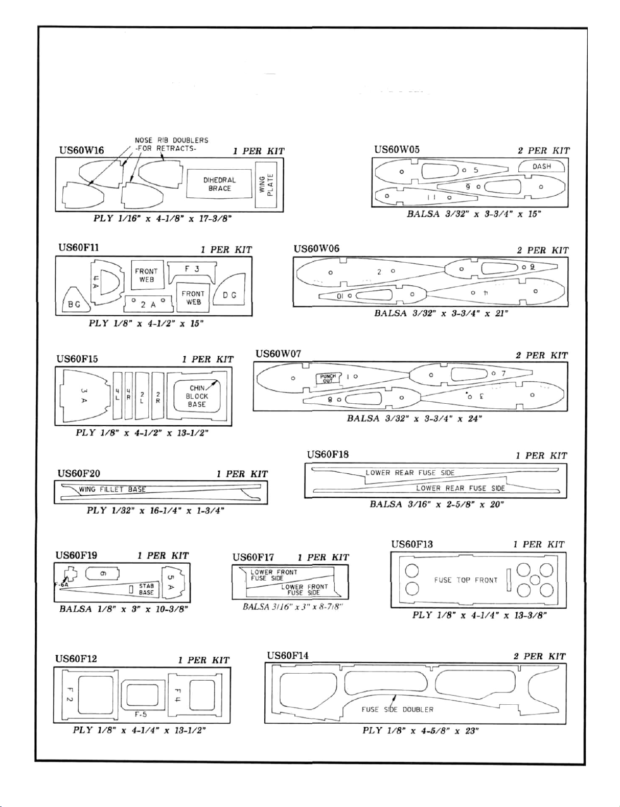
DIE DRAWINGS
Use this drawing to help you identify the die-cut parts
5
Page 6
TYPES OF WOOD
BALSA
BASSWOOO
GET READY TO BUILD
1. Unroll the plan sheets. Re-roll them inside out to make
them lie flat. NOTE: You may cut the fuselage plan into two
sections for case of building on the "Bottom View," by
cutting along the "cut line" shown on the plan.
2. Remove all parts from the box. As you do, figure out
the name of each part by comparing it with the plans and the
parts list. Using a felt tip pen, write the part name or size on
each piece to avoid confusion later. Use the die-cut patterns
shown on page 5 to identify the die-cut parts and mark them
before punching out. Save all scraps. If any of the die-cut
parts are difficult to punch out, do not force them! Instead,
first cut around the parts with an Xacto knife. After punching
out the die-cut parts, use your T-Bar or sanding block to
lightly sand the edges to remove any die-cutting irregularities.
3. Working on a flat surface covered with waxed paper,
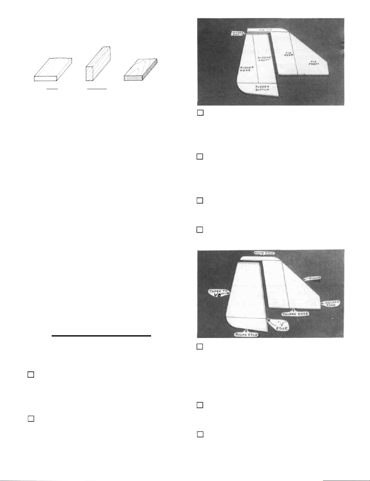
glue the fin front to the fin rear, then glue on the fin tip. Sand
the front of the fin tip to blend with the fin, as shown on the
plan.
4. Using a T-bar or sanding block, sand both sides of
the fin smooth. Then sand the leading edge and top edge to
a rounded shape, as shown on the plan. Draw a centerline
along the trailing edge of the fin to mark the hinge line.
5. Glue the rudder front to the rudder rear. then glue
on the rudder bottom and rudder end.
6. Draw a centerline all around the edges of the rudder.
3. As you identify and mark the parts, separate them into
groups, such as fuse (fuselage), wing, fin and stab (stabilizer), and hardware.
"TAIL FEATHERS"
BUILD THE FIN AND RUDDER
1. Find the following parts: 5/16" balsa fin front, fin
rear, rudder front, rudder rear and rudder bottom. Compare
the parts to the plans to make sure you have the correct parts.
Also find the 5/16" x 5/8" x 5-3/4" balsa stick, and the 1/8" x
3/8" x 11-7/8 "balsa stick.
2. Cut the 1/8" x 3/8" x 11 -7/8" balsa stick into 5 pieces
having lengths of: 2-7/8", 2-7/8", 1-5/8", 1-5/8" and 2-3/4".
The 2-3/4" length is the rudder end. The remaining pieces
are the elevator ends.
7. Using a sanding block and coarse (50 or 80-grit)
sandpaper, sand both sides of the rudder to a taper as shown
on the plans. The trailing edge should end up approximately
1/8" wide and have a rounded shape. (Do not sand to a sharp
edge). Sand the bottom edge to a rounded shape. Sand the
leading edge to a "V-shape" as shown on the plan.
8. Hold the fin and rudder together and mark the fin tip
at the rudder trailing edge. Cut off the fin tip and sand it to
match the rudder as shown on the plan.
9. If you are building a'' taildragger'', check the plans
and mark the location of the tailgear on the rudder. Drill a
6
Page 7
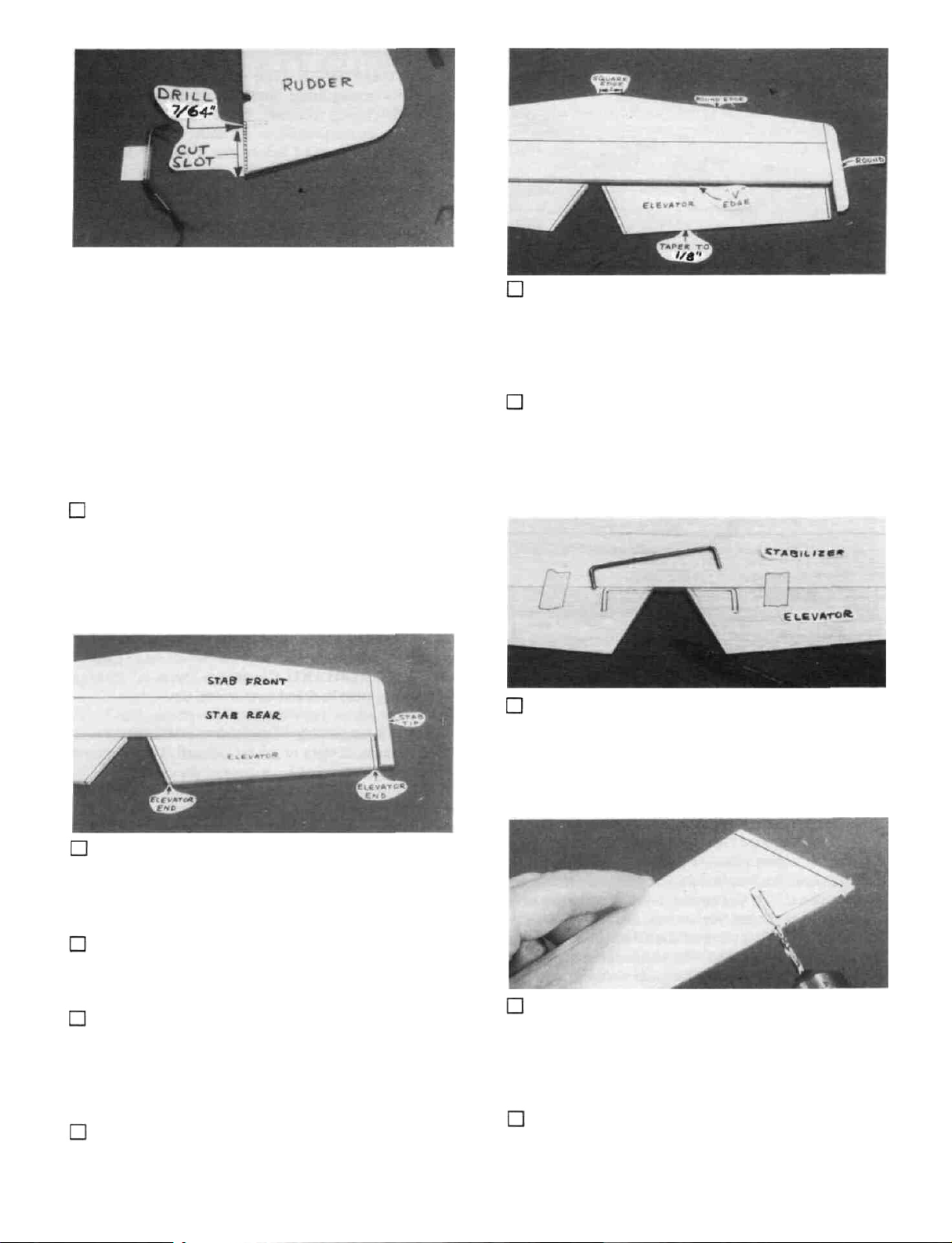
7/64" hole in the rudder, and groove the rudder leading edge
to accept the tailgear wire and the nylon tailgear bearing.
DO NOT GLUE YET! (The hole is drilled slightly oversize
to allow for positioning, and to create a hard epoxy "sleeve"
around the wire).
BUILD THE STABILIZER AND
ELEVATORS
1. Find the following parts: 3/8" balsa stab front, stab
rear and elevators. You'll also need the 3/8" x 5/8" x 11"
balsa stab tip stock, the 1/8" elevator ends that you previously cut, and the 1/8" wire elevator joiner.
6. Sand both sides of the elevators to a taper as shown
on the plans. The trailing edge should end up approximately
1/8" wide and have a rounded shape (do not sand to a sharp
edge). Sand the leading edge to a "V-shape" as shown on the
plan.
7. Temporarily tape the elevators to the stab, providing
1/16" clearance between the elevator end and the stab tip.
8. Lay the 1/8" wire elevator joiner in place on the
elevators and mark its outline using a fine point fell-tip pen.
2. Glue the stab front to the stab rear. Then glue on
the stab tips. Sand the front of the stab tips to blend with the
stab.
3. Glue the elevator ends to the elevators and sand to
blend.
4. Sand both sides of the stab smooth, then sand the
leading edge and lips to a rounded shape. (Leave the center
portion of the LE square). Draw a centerline along the
trailing edge of the stab to mark the hinge line.
5. Draw a centerline all around the edges of the eleva-
tors.
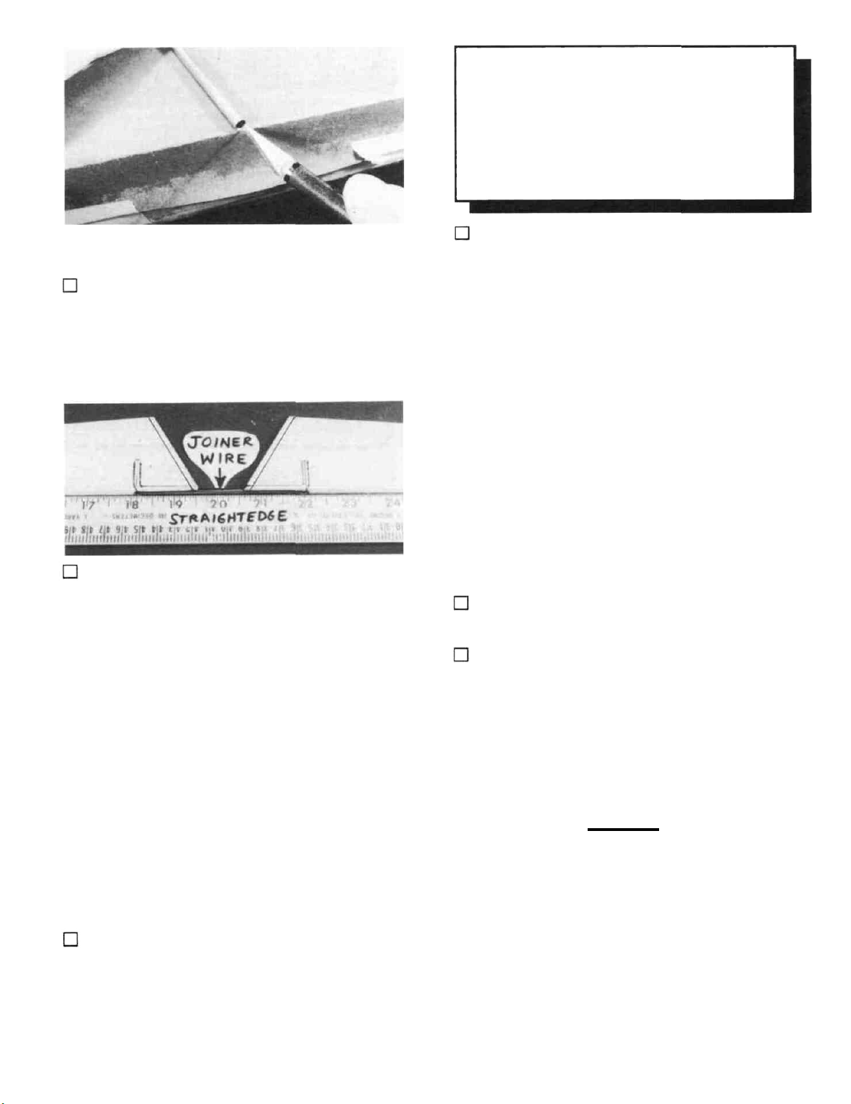
9. Accurately drill holes in the elevators for the 1/8"
wire joiner. Begin by drilling a 1/16" or 5/64" pilot hole, then
drill the final hole to a depth of 7/8" with a 9/64" drill bit.
(The hole is drilled slightly oversize to allow for positioning,
and to create a hard epoxy "sleeve" around the wire).
10. Using an Xacto knife, sharpen the inside of one end
of a 1/8" diameter brass tube and use it to cut grooves in the
7
Page 8
CAUTION!!!: You must use extreme care
when cutting hinge slots with an Xacto knife, to
avoid cutting yourself! If the balsa part breaks
while you are pushing on the knife, the blade could
go into your hand before you know it! A good
precaution is to wear leather gloves and always cut
away from your hand while performing the following steps.
leading edge of the elevators to accept the joiner wire.
11. Roughen the joiner wire with coarse sandpaper, then
clean the wire thoroughly with alcohol to remove any oily
residue.
12. Trial fit the joiner wire into the elevators, then glue
it in using 5-minute or 30-minute epoxy. Work plenty of
epoxy into the holes with a toothpick, then lay the elevator
leading edges along a straightedge to insure perfect alignment.
2. Cut the hinge slots on the accurate centerlines
which you previously drew, using an Xacto knife or a
slotting fork and slotting hook. The recommended procedure
for cutting hinge slots with an Xacto knife is given below.
A. Begin by carefully cutting a very shallow slit in the
trailing edge at the hinge location. This first cut is to establish your cut in the right place, so concentrate on
staying on the centerline and don't cut too deep!
B. Make three or four more cuts in the same line,
going slightly deeper each time. As you make these
additional cuts, work on going straight into the wood.
Continue this process while' 'wiggling'' the knife handle
back and forth until the blade has reached the proper
depth for the hinge.
C. Trial fit the hinge into the slot. If the hinge is
difficult to push in, re-insert the knife and move it back
and forth in the slot a few times to enlarge the slot
3. IMPORTANT! Condition or "break-in" the hinges
by folding them back and forth several times.
4. Insert the hinges into the slots and trial fit the rudder
and elevators in place on the fin and stab. Do not glue the
hinges until after you have covered the model.
INSTALL THE HINGES (Do not glue)
NOTE: One-piece molded polypropylene hinges are sup-
plied in this kit. If you choose to use these hinges or the
"pinned"-type hinges, you may cut the hinge slots at this
time. However, if you choose to use the one-piece hinges that
are paper covered for CA glue installation, you may wait until
after covering before cutting the hinge slots.
1. Lay the rudder and elevators on the plan and mark
the hinge locations. Place the rudder against the fin TE and
transfer the marks over to the fin. Place the elevators against
the stab TE and transfer the marks over to the stab. Note:
Heavy duty hinges should be used on the rudder if you are
building a taildragger.
WING
NOTE: The following instructions explain how to build the
wing on a flat surface, directly on the plans. An alternate
method is to use a Great Planes Wing Jig (available from your
local hobby dealer). Many expert modelers prefer to use a
wing jig for high performance airplanes, as it helps to insure
a straight, warp-free wing, especially if you do not have a
workbench or building board that is perfectly flat. If you
choose to use the Wing Jig, please read the instructions that
are included with the jig before beginning.
8
Page 9
BUILD THE WING PANELS
NOTE: It will be helpful to build the wing on a piece of
"Celotex" or other semi-soft (and flat) surface, into which
you may easily stick pins to firmly hold down the wing parts
while building, to avoid warps.
1. Tape the plan to your flat work surface, and cover
the wing drawing with waxed paper (so you won't glue the
wing to the plan!). NOTE; If your work space is limited, you
may cut the left and right wing half drawings apart.
2. The shaped and notched wing leading edges (LE)
and trailing edges (TE) are fastened together by thin strips of
balsa. Separate them by folding until the balsa breaks. Sand
away the excess balsa that remains along the edges after
breaking them apart, using a T-bar with 100-grit sandpaper.
3. Before using the 1/4" x 1/2" x 30" hard balsa spars,
examine them carefully for possible imperfections. Look for
knots, soft spots, diagonal grain and any other imperfections.
If possible, position each spar so the imperfections (if any) are
on the outer half of the wing panel (toward the tip), where they
will be least affected by high stress. If the spars are warped
slightly, try to "balance them out" by installing the warped
spars in opposite directions (see sketch).
NOTE: If you will be installing a retractable landing gear,
disregard Steps 6 and 7.
6. Note that the wing plan shows two alternate loca-
tions for the main landing gear blocks. Note also that Ribs
W-2, W-3 and W-4 have partial cutouts for each of the two
locations. If you are building your plane as a taildragger, cut
out the front notches in these ribs. If you are building your
plane with a tricycle gear, cut out the rear notches. (If you I
|will be installing retracts, do not cut out any of the notches).
7. Glue the die-cut 1/16" ply landing gear doublers to
ribs W-2, W-3 and W-4. Be sure to glue them to the correct
side of the ribs, as shown on the plan (make a right and a left
set). Sand the doublers even with the edge of the ribs.
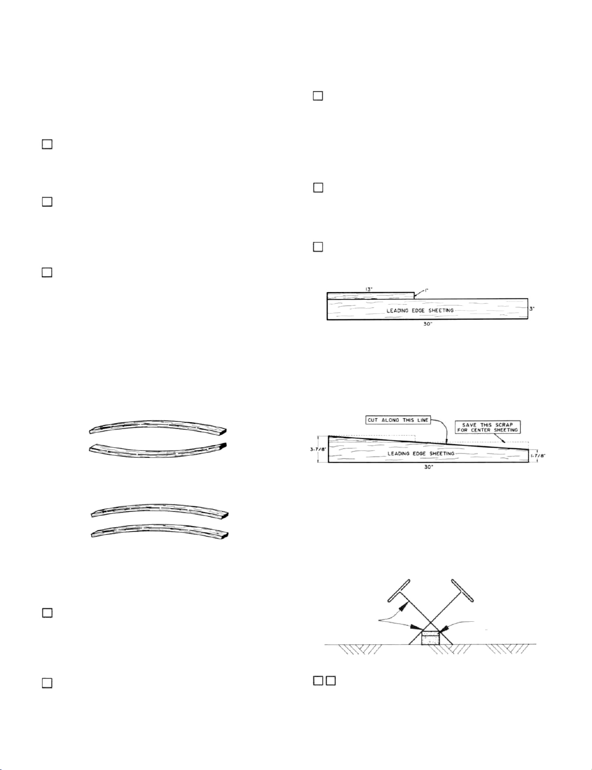
8. Prepare the leading edge sheeting as follows: Edge
glue the 3/32" x 1" x 13" balsa sheets to the 3/32" x 3" x 30"
balsa sheets as shown here ...
TWO WARPED SPARS INSTALLED
THIS WAY WILL RESULT IN A
STRAIGHT WING
TWO WARPED SPARS INSTALLED
THIS WAY WILL RESULT IN A
WARPED WING
4. Find the four 1/8" x 1/2" x 14-1/2" balsa spar
doublers. Sand one end of each spar doubler to a taper as
shown in the "Wing Spar Detail" on the plan. Glue the spar
doublers to the spars, and sand off any excess glue.
Now measure and mark the balsa sheeting (see sketch
below), then cut the angle in the sheeting, cutting along a
metal straightedge for accuracy.
NOTE: Follow steps 9 through 34 to build the RIGHT
wing panel, then repeat these steps to build the LEFT wing
panel
T-Pins
Spar
5. Carefully punch out all the die-cut 3/32" balsa wing
ribs. Sand the edges slightly to remove any die-cutting
irregularities.
9. Pin one of the spars to the plan with the spar
doubler up and toward the root NOTE: The spars are cut
slightly too long. Center the spar on the plan so an equal
amount protrudes on both ends.
9
Page 10

10. Place the ribs on the spar in their approximate
position, but do not glue. NOTE: Make sure ribs W-2,
W-3 and W-4 are installed with the LG notches down, and
W-l is installed with the servo opening pointing up.
Cut first slot to
angle of dihedral gauge
NOTCHED LEADING
EDGE
11. Examine the shaped, notched leading and trailing
edges. Notice that the notches at one end of each LE and TE
are only 2-5/8" apart. These are the notches for W-l and
W-2. Also notice that all notches in the LE and TE are
vertical; however, rib W-l will be installed at a slight angle
using the Dihedral Gauge. Therefore, you should now
modify the notch for W-l by cutting it to the angle of the rib.
You may determine the approximate angle of the cut by
holding the Dihedral Gauge (DG) against the LE as shown
above.
CENTER L.E. VERTICALLY
ON FRONT OF RIBS
L.E.
16. Make sure the ribs are fully down on the plan and
all ribs are inserted into the LE notches. Angle rib W-l
slightly using the dihedral gauge (DG). Glue W-1 to the TE,
LE and bottom spar. Glue all other ribs to the LE and bottom
spar.
12. Insert the rear ends of the ribs into the notches in
the TE, then block up the TE with the 1/4" balsa TE Jig
supplied. NOTE: The narrow end of the TE jig is at rib
W-ll. Pin the jig to the building surface.
13. Pin the TE to the TE Jig, making sure the ribs line
up with the plan.
14. Glue ribs W-2 through W-ll to the TE. (Apply
glue sparingly, to avoid gluing the TE to the TE Jig).
15. Insert the front ends of the ribs into the notches in
theLE. NOTE: Position the LE as shown at the top of the
next column.
17. Glue the top spar in place, making sure you do not
change the angle of W-l.
18. Glue the pre-cut 3/32" balsa vertical grain shear
webs to the rear edge of the spars in all rib bays except
between ribs W-l and W-2. NOTE: You may wish to trial
fit, mark, and trim each web before gluing in. NOTE: The
webs must be securely glued to the spars, but it is not
necessary to glue the webs to the ribs.
19. You will now make a "pocket" for the 1/16" ply
dihedral brace by installing a 3/32" balsa web 1/16" behind
the spars. Sand one of the 3/32" x 2-3/16" x 2-1/2" balsa
horizontal grain webs for a good fit between W-1 and W-2.
(See photo at top of next page.)
10
Page 11

Using the 1/16" ply dihedral brace as a temporary spacer,
glue the 3/32" web to W-l and W-2.
23. Prepare the 3/32" balsa leading edge sheeting by
sanding the front edge to a slight bevel so it will fit snugly
against the back of the leading edge.
3/32" Balsa
L.E. Sheeting
Bevel this
edge
NOTE: It will be helpful to have the following items handy
for the next step... thin CA, thick CA, a wet cloth, masking
tape and T-pins. Read through the following step and go
through a "dry run" before actually gluing.
20. Glue the die-cut 1/8" ply front web to the front
edge of the spars between ribs W-1 and W-2.
NOTE: In the next steps, maintain straightness by keeping
the wing down on the flat surface and on the TE Jig.
21. Lightly sand the lops of the ribs to blend with the
notched trailing edge; then glue one of the 3/32" x 1-3/4" x
30" balsa trailing edge sheets in place. NOTE: The edge of
the TE sheet may not be exactly straight, but just position the
sheet so it slightly overlaps the TE, and any overlap can be
sanded off later.
24. Position the leading edge sheeting at the rear edge
of the notched LE so there is an equal amount protruding on
both ends of the wing. Using thin CA, glue the front (beveled)
edge of the leading edge sheeting to the back edge of the
leading edge. Now wet the top surface of the sheeting so it
will bend easier. Apply thick CA glue to the top edge of the
ribs and to the front half of the spar, then immediately bend
the sheeting down onto the ribs and spar. Hold the sheeting
down with masking tape, pins and your hands until the glue
has set.
22. Before applying the leading edge sheeting in the
next step, use your T-bar to lightly sand off the edges of the
shear webs and smoothly blend the ribs to the spar.
25. Using the 3/32" x 3" x 8-13/16" balsa sheets, glue
the top center section sheeting in place as shown on the plan.
(Use the scraps trimmed from the LE sheeting for the aft
pieces).
11
Page 12

NOTE: If you are installing retracts, disregard steps 26
through 29.
26. Remove the wing from the building board and
trial fit the long grooved hardwood LG block into the notches
in ribs W-2, W-3 and W-4 (see the landing gear detail drawing
on the wing plan for proper positioning). File the notches if
necessary for a good fit. Now use epoxy to securely glue the
block in place.
27. Epoxy the 7/16" x 5/8" x 7/8" hardwood block to
the LG block and to the 1/16" ply doubler on rib W-2, as
shown on the plan and in the photo, then epoxy the small
hardwood block to the other end of the LG block and to the
1/16" ply doubler on rib W-4.
Photo of finished wing with retract mechanism removed.
NOTE: If you will be installing retracts, now is the time to
glue in the 1/16" ply die-cut rib doublers to the front portion
of ribs W-3 and W-4. (Make sure the front rib doublers are on
the outboard side of W-3 and the inboard side of W-4). This
is also the time to install the 1/4" x 13/16" x 2-11/16" ply
retract mounting rails on the bottom of the wing, in the
location shown on the plan. Lock and strengthen the joints
between the 1/4" ply rails and the 1/16" ply rib doublers by
gluing 1/4" balsa triangle stock to these joints. You should
also now do some planning and trial fitting of the retract and
pushrod, customizing the installation as necessary [to|
accommodate your retracts. Installing retracts requires
careful planning and a lot of trial fitting: therefore, you should
take the time now to plan out your installation.
31. With the wing upside down, again use the TE jig
to support the TE. Then install the bottom TE sheeting, LE
sheeting and Center Section sheeting, cutting and fitting the
sheeting around the LG block as necessary. IMPORTANT
NOTE: To insure a straight wing, you must pin or weight
the TE securely down on the TE jig while the bottom
sheeting is glued in place!
28. Drill a 5/32" hole down through the grooved LG
block and the 7/8" block. Line up the drill so you are drilling
straight down through the middle of the 7/8" block.
29. Trial fit the 5/32" diameter main landing gear
wire into the landing gear block at this time. Cut or file the
groove and hole in the landing gear block as necessary for a
good fit
30. Using a razor saw and a sanding block, carefully
cut off and sand all excess sheeting, spars, LE and TE even
with W-l and W-ll.
32. From the 3/32" x 3/8" x 30" balsa sticks, cut and
glue cap strips to all exposed ribs, top and bottom. HINT:
For easier positioning of the cap strips, first mark the location
of each rib on the LE and TE sheeting.
33. Trim the sheeting flush with ribs W-l and W-ll
and sand the entire wing panel smooth. Sand the leading edge
to smoothly blend with the LE sheeting (see the note on the
following page).
12
Page 13

IMPORTANT: The shape of the leading edge
will affect the way this airplane performs snap rolls
and spins. A blunt, rounded leading edge will
"soften" the stall, making the plane very docile
when flying slowly, enabling it to flare nose-high for
very slow landings; however, this may cause the
plane to be a little sluggish when trying to enter a
snap roll or spin. A sharper leading edge will help
the plane enter snap roll and spin maneuvers more
crisply, while sacrificing only a little of the low
speed stability. The leading edge has been approximately pre-shaped to the sharper cross-section, so
try to maintain the same LE radius when sanding to
blend with the LE sheeting. To avoid tip stalls,
make sure the leading edges of both wing panels
have the same shape.
NOTE: 30-minute epoxy is strongly recommended for the
wing joining process.
3. Mix up a batch of 30-minute epoxy and push some
into the dihedral brace slots. Smear epoxy on the spar ends,
and on both sides of the 1/16" ply dihedral brace. Slide the
dihedral brace in place, push the wing panels together and
immediately proceed to the next step.
34. Mark and cut out a 1/16" slot in W-l just behind
the spars, for the dihedral brace.
35. Now go back and repeat Steps 9 through 34 to build
the left
wing panel.
JOIN THE WING PANELS
NOTE: Read steps 1 through 4, then make a "dry run"
through these steps before actually proceeding.
1. Lay a piece of waxed paper down and place the two
wing panels, right side up, so that the W-l ribs are together.
Using the 1-1/8" x 1-9/16" x 9-3/4" balsa wing tip blocks,
block up both wing tips 1-1/8-inch. Sand the wing panels at
the center so they will fit together without a gap.
2. Trial fit the 1/16" ply dihedral brace to make sure
it will readily slide into place. (The photo for this step is at the
top of the next column).
4. With the wing tips blocked up 1-1/8 inch, carefully
align the LE and TE of both wing panels at the center and,
while holding them in correct alignment, apply thin CA glue
to "lock'' the panels together. Do not apply CA glue to any
area that is already coated with epoxy. Allow the epoxy to
fully harden before disturbing the wing.
5. Sand the wing joint smooth all around.
INSTALL AILERON TORQUE RODS
1. Roughen the short end of the aileron torque rods
with 100-grit sandpaper, and file the same end to a wedge
shape. (See sketch on next page).
13
Page 14

File end to
wedge shape
pieces in place with epoxy. HINT: Use masking tape to hold
these pieces to the wing TE, to aid in correct positioning.
2. Roughen the surface of the plastic bearing tubes
with 100-grit sandpaper.
3. Clean the torque rods and bearing tubes with alco-
hol.
4. Find the two grooved, tapered balsa center trailing
edge pieces. Lay them on the plan, mark and cut them off to
match the plan for length and angle at the centerline.
5. Trial fit the torque rods into the center TE pieces.
Determine from the plan where to cut the clearance notches,
which will permit the torque rod horns to travel freely. Also
cut small clearance notches in the wing TE. Note: The
torque rod horns must exit the TOP of the wing!
SAND "FLATS" ON LE AND TE
1. Study the wing plan near the wing centerline. Note
that the center portion of the LE and TE must be sanded flat.
2. Sand approximately 5/32" into the LE at the centerline, and approximately 3/32" into the TE at the centerline.
(The flats will end up approximately 4-1/2" wide at the LE,
and 2" wide at the TE).
FIBERGLASS THE CENTER SECTION
6. Slide the plastic bearings toward the threaded end of
the torque rods, then use a toothpick to apply a small amount
of petroleum jelly to the ends of the plastic tubes (to help
prevent glue from getting inside and locking up the torque
rods).
7. Use 5-minute epoxy or thick CA to glue the plastic
bearing tubes into the grooves in the center TE pieces. Wipe
off any excess glue and allow it to harden.
8. Trial fit the trailing edge / torque rod assemblies
onto the wing trailing edge. Sand the center trailing edge
pieces slightly where they join, for a good fit. Glue these
NOTE; Because of the high stresses in the center of this
wing, Fiberglass reinforcement is REQUIRED. Please do
not omit this important section!
NOTE: If you have previous experience with applying
fiberglass, feel free to use your favorite method, providing
that it results in a strong bond between the glass cloth and the
wood. If this is your first time, we offer the following
suggested method, which is the fastest and easiest we have
seen.
1. Make location marks for the fiberglass reinforce-
ment cloth, 2" each way from the wing centerline.
14
Page 15

2. Trial fit the 4" wide fiberglass cloth in place.
can use a scissors or a paper punch to cut holes in the glass
cloth for the aileron torque rod horns.
You
trailing edge with a sharp Xacto knife followed by a sanding
block.
9. After the glue has set, trim the excess cloth at the
3. Wrap small pieces of masking tape around the
threaded portion of the aileron torque rods to protect them
from the spray adhesive in the next step.
4. Spray a very light mist of 3M "77" Spray Adhesive
on the center section in the area to be glassed. Hold the spray
can at least 12" away from the surface when doing this to
avoid a heavy buildup. The purpose of this is only to give the
wood a little "tackiness". If you apply loo much spray it
could result in a poor glue bond. Allow the spray to dry for
5 minutes before proceeding to Step 5.
10. Carefully sand the edges of the glass cloth with a T-
bar sander with 80 or 100-grit sandpaper. Also, lightly sand
the surface of the glass cloth with a piece of sandpaper held
in your fingers to remove any rough spots. WARNING:
When sanding fiberglass, wear a dust mask to avoid
breathing airborne glass fibers.
INSTALL WING TIPS
NOTE: The wing tips will be carved from the 1-1/8" x
1-9/16" x 9-3/4" balsa blocks.
1. Draw a centerline on the ends of the wing and on the
wing tip blocks.
5. Beginning at the trailing edge, lay the glass tape in
place on the wing. Gently press the cloth in place, working
out all the wrinkles. The "77" spray adhesive should hold
the cloth down to the surface, but will permit you to lift and
reposition the cloth if you make a mistake. Keep working
forward along the top of the wing, around the leading edge,
and along the bottom of the wing, ending at the trailing edge.
Do not attempt to wrap the glass cloth around the trailing
edge.
6. Working outdoors or in a very well-ventilated area
apply thin CA glue to the glass cloth. Begin by running a
bead of glue down the center of the glass cloth strip, then
continue applying the glue in lines until all the cloth has been
secured. Run the thin CA out 1/4" beyond the edges of the
glass cloth to help protect the balsa sheeting when sanding
later. WARNING: This operation produces a larger than
normal quantity of CA fumes, so adequate ventilation is a
must!
7. Inspect the surface of the glass cloth. If any areas are
not glued down, apply a couple more drops of CA glue and
press down with a piece of waxed paper until the glue sets.
8. To make sure the glass cloth is fully "wetted out"
and bonded to the balsa, you may apply more thin CA, a few
drops at a time, and spread it out with a piece of waxed paper.
2. Securely glue a wing tip block to the left end of the
wing, and tack glue a wing tip block to the right end of the
wing, lining up the centerlines you previously drew. You will
later break only the right lip loose and hollow it out.
3. Cut, carve and sand the wing tips to the appropriate
shape as shown on the plan. HINT; Use 50-grit sandpaper
and a sharp wood chisel or razor plane to speed up this
operation. NOTE: Leave the tips oversize in the area of the
ailerons, for now.
15
Page 16

4. Cut the right wing tip loose from the wing and use
a Dremel Moto Tool to hollow out the wing tip. (This will
help to compensate for the weight of the engine head and
muffler).
5. Now securely glue the right wing tip in place.
to make room for the torque rod bearings. Trial fit the ailerons
onto the torque rods and cut or file as necessary until they fit.
Cut 2" off Aileron stock
and glue permanently to TE
6. Cut 2" off one end of the tapered ailerons and glue
the 2" pieces permanently to the trailing edge as shown in the
sketch. This moves the aileron away from the turbulence
caused by the tip vortex. Make sure you carefully line up this
piece with the top and bottom surfaces of the wing.
INSTALL AILERONS
NOTE: Do not glue the aileron hinges until after your model
has been covered.
1. Draw an accurate centerline along the LE of the
tapered balsa ailerons and the wing TE,
2. Check the length of your ailerons against the actual
aileron openings and trim the ailerons as necessary. You
should provide approximately 1/16" gap at each end of the
ailerons.
6. Lay the ailerons on the plan and mark the hinge
locations on the ailerons. Use two hinges near the tips. Place
the ailerons against the wing TE and transfer the marks over
to the wing.
7. Cut the hinge slots in the ailerons and wing TE using
an Xacto knife or hinge slotting tool.
8. IMPORTANT! Condition or "break-in" the hinges
by folding them back and forth several times,
9. Sand the leading edge of the ailerons to the same
"V"-shape as shown on the wing rib detail drawing.
10. Insert the hinges into the slots and trial fit the
ailerons in place on the wing. Do not glue the hinges until
after you have covered the wing.
There should be no hinge gap!
3. Lay the ailerons in place in the openings, with the
torque rods resting on lop of the ailerons. Mark the torque
rod locations on the top of the ailerons.
4. Drill a 7/64" hole in the ailerons at the torque rod
locations, starting at the leading edge centerline and drilling
straight in to the proper depth. (The hole is drilled slightly
oversize to allow for positioning, and to create a hard epoxy
"sleeve" around the wire).
5. Use the sharpened 1/8" diameter brass tube to cut a
groove in the leading edge of the ailerons to accept the
torque rods. Cut these grooves a little larger at the beginning,
11. Now is a good lime to finish the wing tips. Tape the
ailerons on in the neutral position, and sand the wing tips to
blend with the ailerons.
INSTALL WING DOWELS
1. Mark a horizontal centerline on the flat which you
sanded on the wing LE. Also mark a vertical centerlineon the
die-cut 1/8" ply former F-2A (the Wing Dowel Plate).
16
Page 17

2. Holding the die-cut 1/8" balsa F-2A on the leading
edge, in the exact center of the wing, mark the dowel
locations through the dowel plate holes.
3. Remove F-2A and double check to make sure the
dowel locations are both the same distance from the wing
center joint
4. It is important that you now drill the dowel holes
accurately! To insure accurately positioned holes, begin by
drilling small (1/8") holes in the center of the marked locations. Then gradually increase drill bit sizes until you have
finally drilled the holes to 1/4" diameter. The final holes you
drill must extend 3-3/4" into the wing to penetrate the front
webs. NOTE: Try to drill straight in.
3. Sand the wing bolt plate flush with the wing TE.
FILL LANDING GEAR SLOTS
1. Temporarily install the main LG wires.
2. Check the plan for the location of the nylon landing
gear straps and temporarily install them, using #2x3/8 sheet
metal screws.
NYLON LANDING
GEAR STRAP
#2X3/8" SHEET
METAL SCREW
5. Sand one end of each wing dowel to a rounded or
pointed shape. This is the end that will be inserted. Do not
sand the other end at this time.
6. Trial fit the dowels into the dowel holes, and trial fit
the dowel plate over the dowels. If the dowels fit too tightly,
you may enlarge the holes slightly using a round file, or you
may sand the dowels down slightly. Do not glue the dowels
in place at this lime.
INSTALL WING BOLT PLATE
1. Mark a centerline on the die-cut 1/16" x 3-15/32" x
1-5/8" ply wing bolt plate.
notched LG blocks and sand flush with the surface of the
wing. This will aid in covering later.
INSTALL RETRACTS (OPTIONAL)
NOTE: Hardware for retract installation is not included in
the
kit
1. Study the retract drawings on the plan. and the
I installation instructions provided with your retracts, and plan
your retract installation before proceeding,
2. Position the wing boll plate on the bottom of the
wing, and line it up with the wing TE and centerline. Glue it
in
place.
Photo shows finished wing with retract installed.
2. Cut an opening in the bottom LE sheeting for the
17
Page 18

retract mechanism. Cut a clearance slot in rib W-3 for the LG
wire. Cut an opening in the bottom LE sheet and in rib W-2
for the wheel well.
FUSELAGE ASSEMBLY
3. lEnclose the wheel well by running vertical grain
1/16" balsa between the bottom and top sheeting; or you may
make the wheel well from an appropriately-sized styrofoam
cup.
of the spars) for your retract servo, and bend and fit a pushrod
to run between the servo and the retract mechanism. Run the
pushrod just under the top LE sheeting until it passes over the
wheel well, then make two 90-degree bends and connect it to
the retract mechanism.
5. Temporarily mount yourretract servo and trial fit all
retract components. Test the operation of your retracts
making sure they operate freely and reliably. Also make sure
they
"lock"
in
both the up and down positions.
PREPARE FUSE SIDES
1. Lay one of the shaped 3/16" balsa fuselage sides in
place on the fuselage plan side view. Carefully position the
fuse side so the front edge lines up with the front ofF-1 on the
plan. Tape or pin the fuse side so it can't move. NOTE: The
fuse side may be a little longer at the rear than indicated by the
plan. This is as it should be.
2. Carefully position the die-cut 3/16" balsa lower
front fuse side so the rear edge lines up with the front of the
wing saddle opening on the plan (the rear edge ofF-2A). You
may have to lightly sand the top edge of the die-cut 3/16"
balsa for a good fit against the bottom edge of the fuse side.
Edge glue the lower front fuse side to the fuse side. NOTE:
Use waxed paper under the balsa to avoid gluing to the plan.
Photo shows
6. Blend the bottom sheeting as neatly as possible
around the retracts.
1. Use polyester resin or 30-minute epoxy thinned with
finished
wing with
retract
installed.
alcohol to fuelproof the entire retract well area.
3. Carefully position the die-cut 3/16" balsa lower
rear fuse side so the vertical front edge lines up with the rear
of the wing saddle opening on the plan (the front edge of
F-4). Edge glue the lower rear fuse side to the fuse side.
4. Trim and sand off the die-cut "bumps" from the
front and rear portion of the lower rear fuse side, blending
with the upper fuse side.
5. Sand the fuse side smooth on both sides using a Tbar and 100-grit sandpaper, then repeat the above steps to
make the other fuse side.
18
Page 19

6. Find the two die-cut 1/8" ply fuselage doublers and
the four die-cut 1/8" ply firewall spacers. Note that the
spacers are marked "2 L", "2 R". "4 L", and "4 R".
Use the #2 firewall spacers if you will be install-
ing a 2-cycle engine such as the OS Max 61 SF.
Use the #4 firewall spacers if you will be install-
ing a small 4-cycle engine, such as the OS FS 70
Surpass.
If you will be installing a larger (longer) 4-cycle
engine, such as the OS FS 91 Surpass, do not use any
firewall spacer on the right side, and use the 1/8" x
1/8" x 3-5/8" hardwood stick as a firewall spacer on the
left side.
PLAN IT OUT! It is important that the fuse doubler and fuse
side line up along the top edge and the front of the wing
opening. While holding in position, apply thin CA glue
around all the notches and lightening holes, then around the
edges. Make sure you apply sufficient glue so it flows under
the doubler to produce a strong bond. NOTE: The narrow
and wide firewall spacers will automatically position the
firewall to result in 2-degrees of right engine thrust.
9. Glue the tapered balsa tail filler to the aft end of one
of the fuse sides and sand it even with the top and bottom
edges.
10. From the 1/4" balsa triangle, cut pieces to fit be-
tween the tail filler and the rear of F-4, along the bottom
inside of both fuse sides. Glue in place.
7. Edge glue the appropriate firewall spacers to the
front edge of the fuselage doublers. Note that the spacers are
not the same size. They will automatically set the engine at
the required 2-degrees right thrust.
8. Carefully position the fuselage doublers on the fuse
sides, making a RIGHT and a LEFT side. The doubler with
the smaller firewall spacer goes on the right fuselage side ..
11. Sand the aft ends of the balsa triangle to a taper,
which will permit the fuse sides to be pulled together at the aft
end. NOTE: The taper shown in the photo is approximate
and may have to be modified during assembly.
ASSEMBLE LOWER FUSELAGE
1. Tape the fuselage plan to your workbench and cover
the Fuse Bottom View with waxed paper.
NOTE: The fuselage is assembled upside down.
2. Pin or tack glue (using 3M "77" Spray Adhesive)
the 1/8" die-cut balsa stab base accurately in position on the
plan. Align the front edge of the stab base with the line on the
plan.
19
Page 20

3. Accurately position the two pre-cut 1/4" x 1/2" balsa
cross-braces on the plan, and pin them in place behind F-4
and F-5. Note: The front cross-brace (at F-4) extends only
out to the doublers.
the plan and hold it securely in place with pins, tape or
weights (or you may spray it lightly with 3M "77" spray
adhesive, to hold it firmly but temporarily down on the plan).
7. Trial fit (do not glue) the following parts together
Fuse top, fuse sides, die-cut 1/8" ply F-2. F-3, F-4 and the
die-cut 1/8" ply Chin Block Base. Check the fit of all parts
and trim, file or sand as necessary for a good fit. Pull the aft
ends together and re-sand the 1/4" triangles if necessary.
4. Trial fit formers F-4 and F-5 to the front of the Cross-
braces (the formers are upside down), and sand the edges of
the formers slightly to match the angle of the fuse sides. Glue
the formers to the cross-braces, making sure that each
former is installed perpendicular to the building surface.
5, Insert F-6 upside down in the rear of the slot in the
stab base. Sand the edges of F-6 slightly to match the angle
of the fuse sides. Align F-6 perpendicular to the stab base and
glue it in place.
8. Once you have everything fitting properly, re-as-
semble the above parts, using clamps, pins. tape and weights
to hold everything together and flat on the workbench. Make
sure F-2 is pushed as far forward as possible, and F-4 is
pushed as far aft as possible. There should be waxed paper
underneath to prevent gluing the fuse to the plan. Apply thin
CA glue to the joints, then follow with thick CA glue in any
joints that are not tight fitting.
9. Sand the bottom of the fuse to remove any excess
glue, and to provide a flat surface for the sheeting.
6. Accurately position the 1/8" die-cut ply fuse top on
pieces of cross-grain sheeting to the bottom of the fuse,
beginning at the front of F-4 and running to the aft end of the
fuse.
11. Now you may remove the fuselage from the work
surface and sand the edges of the bottom sheeting flush with
the fuse sides.
20
Page 21

12. Find the 1/4" ply wing hold-down block and trial fit
it into the notches in the fuse side doublers, sanding as
necessary for a good fit. Glue the hold-down block in place
securely, using 30-minutc epoxy, then cut pieces of 1/4"
balsa triangle and glue them in place above and below the
hold-down block. Sand the triangles flush with the wing
saddle.
13. The 1/4" ply firewall (F-l) location and size will
vary, depending on which engine you install. The location
has been set by the firewall spacers. The firewall supplied in
your kit is the correct size if you are installing a .91 4-stroke
engine; however, if you are installing a smaller engine, such
as a .70 4-stroke or a .61 2-stroke, you will have to cut the
firewall down to the correct size. The fuse plan shows the
firewall sizes and engine mounting required for the three
locations. Cut the firewall to size and sand the sides and
bottom at an angle to match the fuse. Trial fit to make sure it
will fit correctly before proceeding to the next step.
15. Use 30-minute or 5-minute epoxy to securely glue
F-l to the fuse sides, holding with clamps or tape until the
glue has firmly set. NOTE: Before the glue sets. double
check to make sure F-1 is properly aligned with the top and
bottom edges of the fuselage, and fully back against the
firewall spacers. After the glue has fully hardened, sand off
the front of the fuse sides flush with the front of F-l.
16. Cut pieces of 3/8" balsa triangle to fit around the aft
edges of F-1, and glue them in place.
14. Before installing the firewall (F-l), you may drill
F-l for your engine mountand install the 6-32 blind nuts. You
may cut out the appropriate F-l drawing from the plans, tape
it to F-l and use it as a guide for drilling the four 5/32" holes.
If you will be using a mount not shown on the plans you'll
have to determine the correct mounting position. Note that
the mount should not be positioned on the vertical and
horizontal centerlines of F-1, but should be offset slightly
above the centerline and slightly toward the left side. (When
taking measurements off the plan, keep in mind that the plan
shows the bottom view of the airplane). Drill the holes and
install the blind nuts on the back ofF-1, pressing them in with
a pliers or a vise.
6-32
Blind Nut
DRILL ENGINE MOUNT
(Great Planes MM60L mount)
1. Place the engine pointing straight ahead on the
mount and mark the mounting hole locations on the mount.
At the marked locations, accurately drill 7/64" (or #36) holes.
NOTE: If you have access to a drill press, use it for drilling
these holes to insure that they are drilled vertically.
2. Now you may use one of the following methods to
attach your engine to the mount:
Method 1: Screw the #6 x 1" sheet metal screws
(provided in the kit) through the engine mounting flange and
into the mount. When first installing these screws, put a drop
of oil into each screw hole.
21
#6 x 1" Screw
Page 22

Method 2: Cut threads into the holes you just drilled
using a 6-32 tap and tap wrench. If you use this method you'll
have to supply your own bolts (6-32 x 1" socket head cap
screws) for attaching the engine to the mount. NOTE; 8-32
hardware is recommended if you are installing a 4-cycle
engine.
INSTALL SERVOS AND PUSHROD GUIDE
TUBES
NOTE: Although you may choose to wait until later, this is
the best time to install the pushrod guides, because the
fuselage is wide open and it is very easy to work inside.
IMPORTANT: Before proceeding, plan your servo and
pushrod installation. Especially note which side of the
fuselage the throttle pushrod and nose gear pushrod (if any)
will be located. Remember that the throttle arms of 2-cycle
and some 4-cycle engines are on opposite sides. It will be
helpful to actually sketch your pushrod locations on the plans
with a pencil. It is desireable for the throttle pushrod (and the
nosegear steering pushrod) to run along the sides of the
fuselage. It is also desireable (but not essential) for the rudder
and elevator pushrods to cross inside the fuselage, to avoid
any sharp bends.
the brass tube method gives a much neater cut). Determine
the location of these holes from the plans. You may chuck
this brass tube in an electric drill to aid in getting through
F-6.
5. Insert the plastic pushrod tubes through the holes
you just cut and through formers F-6, F-5 and F-4.
1. Set the fuselage upside down on blocks at least
1-inch high.
2. Trim the 3/16" x 1/2" x 3-5/8" ply servo rails to fit
between the fuse side doublers in the locations shown on the
plan. Temporarily mount your servos to the rails, then glue
the rails to the fuse side doublers. Lock the rails in place by
gluing scraps of plywood on the top and bottom of the rails.
3. Sand the outer surface of the pushrod guide tubes
with 100-grit sandpaper to provide a surface to which the glue
will adhere.
4. Use an Xacto knife to sharpen one end of a piece of
3/16" (outside diameter) brass tubing, then use this tubing to
cut the pushrod exit holes (you may use a 3/16" drill bit, but
6. Route the pushrod tubes according to your
radio installation plan. Temporarily insert the 34"
pushrod wires into the tubes and hold them in the
correct position at the servo end. Keep the tubes as
straight as possible. Glue the tubes to the fuse sides
at the rear exit points using thin CA glue. Use scraps
of 1/8" balsa to anchor the tubes to F-5. Do not anchor
the tubes to F-4 at this time, to allow for slight
adjustment of their positions later.
7. Cut off the tubes at the exit points and sand them
flush with the fuse sides using a sanding block.
8. Temporarily install the engine mount, nosegear
(and nosegear steering arm if you are building a tricycle
configuration).
9. Cut 1/4" off the end of the steering arm, then drill
a 3/16" hole in F-l, just above the outer hole of the arm.
NOTE: The drill should be aimed toward the rudder servo to
avoid tight bends in the pushrod. The photo for this step is at
the top of the next page.
5/32" Collar
Steering Arm
Cut
off
end
6-32 x 1/4" Screw
22
Page 23

10. With the engine resting on the mount, plan the
throttle pushrod routing. The pushrod should be located as
close as possible to the fuse sides (to allow room for the fuel
tank), and the guide tube should not have any tight bends.
Drill a 3/16" hole in F-l for the throttle pushrod guide tube.
3. Insert the die-cut 1/8" ply F-2A in place against the
back of F-2 (do not glue).
4. Insert the 1/4" wing dowels into the wing so they
stick out only 1/8".
5. With the fuselage upside down on a flat surface, trial
fit the wing into the wing saddle. If the wing is slightly too
large (front to rear) to fit into the saddle, sand the rear edge of
the saddle and the wing trailing edge slightly until it fits.
11.
Drill or carve holes in F-2 and F-3 for the guide
tubes. Cut the remaining 36" plastic pushrod guide tube in
half and trial fit the tubes in the fuselage. (Also see the photo
on page 35.)
12. Sand the plastic pushrod guide tubes with 100-grit
sandpaper, then glue them in place. Trim and sand the tubes
flush with the front of F-l.
13. Cut the pushrod wires (supplied) to the required
lengths and temporarily install the throttle and nose gear
pushrods. NOTE: A 34" wire, threaded one end, is supplied
for the throttle pushrod, and a 19" wire (no threads) is
supplied for the nosegear pushrod.
14. Now remove the pushrod wires, engine, engine
mount and servos.
MOUNT THE WING TO THE FUSE
1. Sand the top surface of the fuse to remove any excess
glue so the fuse will lie flat on the workbench.
2. Sand the entire wing saddle area lightly until the fuse
side doublcrs and fuse sides are flush.
Measurements must be equal
6. Carefully align the wing in the saddle as follows:
If you have drilled the dowel holes accurately, the wing
should now be centered, side to side. Measure down from the
bottom of both tip ribs to the flat surface. If the measurements
are not equal (within 1/16"), sand the saddle slightly until the
wing sits level in the saddle. Also measure from the rear
comer of each wing tip to the tail end of the fuselage. These
measurements must also agree within 1/16". If not, shift the
wing slightly until they do. With the wing in this position you
may now check the wing incidence using an "incidence
23
Page 24

meter" or by measuring down to the flat surface from the
center of the leading and trailing edges. The measurements
should be the same (zero degrees incidence). CAUTION: If
your flat surface is not level, you will get erroneous incidence
readings! If you are working on a flat surface that is not level,
you must set the wing incidence the same as your flat surface.
7. After making the necessary corrections to align the
wing, tack glue F-2A to F-2 with a couple drops of CA. Also
make alignment marks on the wing TE and the front ofF-4
so you may easily re-align the wing later.
8. Remove the wing and securely glue F-2A in place by
flowing thin CA into the wing dowel holes and around the
edges. Follow up with thick CA in any gaps around the edges.
12. Holding the wing firmly in place, drill 13/64" holes
at the locations you marked in step 11, drilling down through
the 1/16" ply wing bolt plate and through the 1/4" ply holddown block in the fuselage. Try to drill straight in, perpendicular to the 1/16" ply bolt plate. IMPORTANT!: Do not
allow the wing to move while drilling!
13. Remove the wing and re-drill the holes in the wing
only to 1/4".
9. Drill 1/4" holes through F-2 using the holes in F-2A as
a guide.
10. Use a pliers to grasp the ends of the wing dowels and
pull them out. Now you may slightly round (or chamfer) the
ends of the dowels for easier insertion into F-2A. Mix up a
batch of 30-minute epoxy, use a long stick to work some
epoxy into the dowel holes, smear epoxy on the dowels, then
re-insert the dowels into the wing, leaving them protrude
3/8". Wipe away all excess epoxy, then allow the epoxy to
fully harden.
11. Study the wing plan to determine where the wing
bolt holes are to be drilled. By measuring, transfer the locations to the wing bolt plate on the bottom of the wing. After
marking the bolt locations, replace the wing in the saddle and
re-align it accurately, as in step 6.
1/16" WING BOLT PLATE
13/16"
14. Use a 1/4-20 tap and a tap wrench to cut threads
the ply hold-down block in the fuselage.
15.
Harden the threads in the hold-down block with thin
CA glue, then re-tap the threads after the glue is completely
dry.
16. Trial fit the wing to the fuse using the two 1/4-20
nylon bolts provided. You may cut the bolts off to their proper
length, so they protrude about 1/4" below the hold-down
block in the fuselage.
1/4 - 20 Nylon Wing Bolt
17. Later you will apply foam wing seating tape or
silicone sealer to the wing saddle. To allow space for this
wing cushion material, you may sand the saddle slightly in
the areas where the wing touches the saddle, to provide a
small gap.
in
Drilling locations
18. Sand off the bottom edge of F-2 and F-2A flush with
the bottom of the chin block base. And, while you're at it,
24
Page 25

sand the entire fuse bottom, forward ofF-2A, in preparation
for installation of the chin block.
FIT FUEL TANK and FUELPROOF TANK
COMPARTMENT
1. Assemble your 11 to 14 oz. fuel tank. Werecommend bending the brass tubes as shown in the photo to prevent
them from cutting through the silicone fuel lines if pressed
against the firewall. (Try not to' 'kink'' the tubes when bending, however).
2. Try sliding the tank in through F-2. If the opening is
not large enough, sand or file the opening until the tank slides
in easily.
3. Temporarily install the engine mount and note how
far the mounting screws protrude into the fuel tank compartment. Remove the screws and cut them off so they do not
protrude more than 1/8" (to prevent puncturing the fuel tank).
5. Now remove the engine mount and fuelproof the
inside of the fuel tank compartment and the front of F-l by
brushing on a coat of polyester resin or 30-minute epoxy
thinned with alcohol. NOTE: Later when installing the nose
pieces, you will fuelproof the chin block before installing it.
6. You may permanently install the fuel tank at this
time, or you may wait until the plane is nearly completed. If
you do it now it will be easier to feed the fuel lines through
F-1, and to make sure there are no kinks in the lines; however,
you'll have to work around them while completing the nose.
When you install the tank, be sure to cushion it from vibration
and prevent it from moving by surrounding the tank on all
sides (and front) with latex foam rubber. Leave a few inches
of extra fuel tubing in front of F-l (you can cut off the excess
later). The photo shows how to route the fuel tubing to
prevent kinking.
INSTALL TURTLE DECK
4. Drill two holes (7/32" or size to fit your fuel tubing)
near the top of F-l for your fuel tubing vent and fill lines. The
location of these holes will depend somewhat upon the type
of engine you are using, etc. It is OK to drill the holes in the
upper left and upper right comers, but we prefer drilling both
holes in the upper right comer (as viewed from the rear) for
easier access.
You'll need the following pans: Die-cut 1/8" ply F-3A,
F-4A. and Backrest Gauge (BG); die-cut 1/8" balsa F-5A
and F-6A; two 1/4" x 1/4" x 27" balsa turtle deck stringers;
two 3/32" x 3-1/4" x 28-1/4" balsa turtle deck sides; the 1/2"
x 2-3/8" x 26" balsa turtle deck top block and a roll of
masking tape.
1. Glue the die-cut 1/8" ply "backrest" (F-3A) to the
fuse top, using the "backrest gauge" (BG) to set it at the
25
Page 26

correct angle. NOTE: The gauge is used only for setting the
angle (do not glue the gauge in).
2. Glue F-4A to the front of F-4.
Glue F-5A to the front of F-5.
Glue F-6A to the front of F-6 (insert the F-6A tab
through the slot in the stab base).
7. Glue the bottom edge of the sheeting to the top of the
fuse sides.
3. Glue the 1/4" x 1/4" x 27" balsa stringers to the
formers. HINT: If F-3A is slightly warped, you may
straighten it during this step by twisting it straight while
gluing the stringers. Trim and sand the ends of the stringers
flush with the front of F-3A and the rear of F-6A.
4. Use a sanding block to sand the sides of the stringers
to blend with the formers (see the cross-section drawings on
the plan). Also use a long sanding block to sand the stringers
and the tops of the formers in a straight line from F-3A to
F-6A.
5. Prepare the turtle deck sides by cutting the two
3/32" x 3-1/4" x 28-1/4" balsa sheets to the angle shown in the
following sketch.
8. Wet the outside surface of the sheering with a damp
rag to permit easier bending. Apply thick CA glue to the
edges of the formers and the stringers, then immediately bend
the sheeting around the formers and onto the stringers.
HINT: This requires about 5 sets of "hands," so use several
long pieces of masking tape to pull the sheering together;
then, working a small section at a time, add CA and press the
sheeting to the stringers.
9. Trim and sand the sheering flush with the front of
F-3A and the rear of F-6A.
6. Trial fit one edge of the sheeting down onto the top
of the fuse side. Sand the edge of the sheering if necessary,
for a good fit
10. Using a long T-bar or sanding block with 80-grit
sandpaper, sand the sheering and stringers flush with the top
edges of the formers.
26
Page 27

NOTE: The turtle deck is designed to be as light as possible,
while still providing sufficient durability for normal use. If
your airplane will be handled by "ham-fisted" people who
like to squeeze hard when holding the airplane in the turtle
deck area, you may want to add an extra 1/4" x 1/4" balsa
stringer on the inside of the turtle deck sheeting, between
F-3A and F-4A, about halfway down.
HINT: For a super-smooth and uniform finish on your turtle
deck, cut a 2-1/4" x 11" strip of 320 or 400-grit wet-or-dry
sandpaper, and work it like a "shoe-shine cloth" across the
top of the turtle deck.
11. Glue the 1/2" x 2-3/8" x 26" balsa turtle deck top
block to the tops of the formers, stringers and sheeting, then
trim the ends of the top block flush with F-3A and F-6A.
HINT: In the next step it will be helpful in keeping the
top block symmetrical if you first mark a centerline on the
top of the top block from front to back (this is a line from the
centerline of F-3A to F-6A).
ASSEMBLE THE NOSE SECTION
1. Find the 1/4" x 1/4" x 10" balsa cockpit sides. Cut
off one end of each stick at an angle to fit the front edge of the
backrest (F-3A).
2. Glue the cockpit sides to the top edge of the fuse
sides and to F-3A. The outside edge of the cockpit sides
should be flush with the outside edge of the fuse sides.
3. Measure, mark and sand off the cockpit sides according to the sketch. Then sand the top front comers of the
fuse sides on the same angle, to blend with the cockpit sides.
12. Carve and sand the top block to blend smoothly with
the sheeting (see the cross-sections on the plan). HINT: Use
a razor plane (or a sharp wood chisel) and a sanding block
with 50-grit sandpaper for rough shaping the top block.
4. Attach the engine mount to F-l, and attach the
engine to the mount Remove the nose gear.
5. From a scrap of 1/32" ply, cut four small pieces and
tack glue them to the 1/16" ply spinner ring as shown, using
a very small amount of thick CA (these will be removed
later). IMPORTANT NOTE: If you have chosen to use
shock-absorbing rubber engine mounts, then you must provide more space between the spinner ring and the spinner
27
 Loading...