

Page 1
INSTRUCTION BOOK
PLEASE READ THROUGH THIS INSTRUCTION BOOKLET IN ITS ENTIRETY BEFORE BEGINNING
ASSEMBLY. IT CONTAINS IMPORTANT INSTRUCTIONS AND WARNINGS CONCERNING THE ASSEMBLY
AND USE OF THIS MODEL.
WARNING! THIS IS NOT A TOY!
This R/C kit and the model you will build is not a toy! It is capable of serious bodily harm
and property damage. IT IS YOUR RESPONSIBILITY AND YOURS ALONE-to build this kit
correctly, properly install all R/C components and flying gear (motor, batteries, pushrods, etc.)
and to test the model and fly it only with experienced, competent help in accordance with all
safety standards and common sense as set down in the Academy of Model Aeronautics Safety
Code. It is suggested that you join the AMA and become properly insured before you attempt
to fly this model. IF YOU ARE JUST STARTING R/C MODELING, CONSULT YOUR LOCAL
HOBBY SHOP OR WRITE TO THE ACADEMY OF MODEL AERONAUTICS TO FIND AN EXPERIENCED INSTRUCTOR IN YOUR AREA.
Academy of Model Aeronautics
1810 Samuel Morse Dr.
Reston, VA 22090
(703) 435-0750
PO BOX 788 URBANA ILLINOIS 6180) 217/3672069
Page 2

TABLE OF CONTENTS
INTRODUCTION....................................................2
PRECAUTIONS
KEEP IT LIGHT
RADIO SELECTION
SPEED CONTROL SELECTION
BATTERY SELECTION.......................................... 3
BATTERY
PROPELLER SELECTION
OPTIONAL LANDING GEAR
SELECTION OF WHEELS
GLUES (ADHESIVES)
OTHER ITEMS REQUIRED
SUPPLIES & TOOLS NEEDED
COMMON ABBREVIATIONS
TYPES OF WOOD
PERSPECTIVE DRAWING..................................... 5
GET READY TO BUILD
DIE PATTERN .......................................................5
FUSELAGE..........................................................................6
PREPARE FUSELAGE SIDES
ASSEMBLE FUSELAGE........................................ 9
SAND THE FUSELAGE ........................................ 12
TEMPORARILY MOUNT LANDING GEAR ........ 13
DRILL HOLE FOR TAIL SKID
CUT FIN SLOT IN FUSE TOP .............................. 13
INSTALL
INSTALL SERVO RAILS
INSTALL WING PLATE
FIN AND STABILIZER ...................................................... 15
BUILD THE FIN AND RUDDER
BUILD THE STABILIZER AND
ELEVATOR
MAKE
THE HINGES
TEMPORARILY INSTALL HINGES
TEMPORARILY MOUNT CONTROL HORNS ..... 17
MOUNT THE STABILIZER .................................. 18
MOUNT THE FIN
WING...................................................................................20
BUILD
THE WING PANELS
.......................................................
......................................................
...............................................
.............................
CHARGER
RUDDER
...........................................................
SELECTION
......................................
.......................................
............................................4
....................................
...................................................
.........................................
CABLE
.................................................
GUIDES
......................................
.......................................
.............................................
.......................
................................
..............................
................................4
................................
.............................
..................
..........................
....................
................................
13
13
14
14
15
15
15
16
19
20
3
3
3
4
4
4
5
6
JOIN THE WING HALVES .................................. 23
2
3
3
4
4
COMPLETION.................................................................. 27
FINAL ASSEMBLY............................................................ 30
PRE-FLIGHT..................................................................... 32
FLYING .............................................................................. 34
APPENDIX ......................................................................... 34
PARTS LIST....................................................................... 39
FIBERGLASS CENTER JOINT............................ 23
MOUNT WING TO FUSELAGE
INSTALL WING FAIRING
INSTALL AILERONS .......................................... 25
INSTALL AILERON SERVO AND HORNS ........ 26
MAKE
THE ELEVATOR PUSHROD
MAKE
THE AILERON PUSHRODS
PREDICT THE FINISHED
FLYING WEIGHT................................................ 28
INSTALL VELCRO .............................................. 29
BALANCE THE AIRPLANE LATERALLY ......... 29
FINAL SANDING
COVERING.......................................................... 29
ADD TRIM
INSTALL ALL COMPONENTS ........................... 30
BALANCE YOUR MODEL
FINAL HOOKUPS AND CHECKS
CHARGE
TEST THE MOTOR OPERATION
FIND A SAFE PLACE TO FLY
GROUND
RANGE
MOTOR SAFETY PRECAUTIONS
AMA SAFETY CODE
PROPER CARE OF YOUR GOLDFIRE
MOTOR................................................................ 34
OVERLOADS
HOW TO ACHIEVE TO BEST
PERFORMANCE FROM YOUR ELECTRIC-
POWERED MODEL............................................. 35
THE BATTERIES
CHECK THE MODEL
CHECK
.................................................29
...........................................................
YOUR RADIO
..........................................
.......................................................
..........................
..................................
...................
....................
..................................
.......................
.................................
........................
............................
.........................
...........................
......................
24
25
27
28
30
31
32
32
32
33
33
33
33
34
34
INTRODUCTION
Congratulations! Thank you for purchasing the Great
Planes ElectroStreak! Tom Stryker's original design for this
airplane was first featured in the November, 1987 issue of Model
Aviation magazine. We built this airplane "just for the fun of it",
and we were so impressed with its performance on our standard
"Thrustmaster" motor, we knew it would be a success as a kit!
During the testing process, the new Goldfire motor was developed, and we found this motor to be ideally suited for the
ElectroStreak, due to its tremendous power.
This is one of the very few easy to build electricpowered airplanes in kit form that really does provide exciting and
satisfying acrobatic performance without the need for expensive
cobalt motors or exotic building materials. It is a very smooth and
stable flier, yet it will perform all basic pattern maneuvers, such
as rolls, inside and outside loops, snap rolls, spins, inverted flight,
Immelmans, hammerheads, Cuban 8's, and many others.
While not a beginner's plane, the ElectroStreak is great
for the intermediate or advanced flyer who wants real performance, with the quiet convenience of electric power.
Please Inspect all parts carefully before starting to
build! If any parts are missing, broken or defective, or if you
have any questions about building or flying this airplane,
please call us at (217) 367-2069 and we'll be glad to help. If you
are calling for replacement parts, please look up the part
numbers and the kit identification number (stamped on the end
of the carton) and have them ready when calling.
PRECAUTIONS
1. You must build the plane according to the plans and
Instructions. Do not alter or modify the model as represented by
the plans, as doing so may result in an unsafe or unflyable modeL
2. You must take time to build straight, true and strong.
2
Page 3

3. You must use a proper R/C radio that is in first class
condition, the correct size motor and correct components
(wheels, etc) throughout your building process.
4 You must properly install all R/C and other compo-
nents so that the model operates properly on the ground.
5 You must test the operation of the model before the
first and each successive flight to insure that all equipment is
operating and you must make certain that the model has remained
structurally sound.
6. You must fly the model only with competent help
from a well experienced R/C pilot if you are not already an
experienced and knowledgeable R/C pilot at this time.
Note: We, as the kit manufacturer, can provide you with
a top quality kit and great instructions, but ultimately the quality
and flyability of your finished model depends on how you build
it, therefore, we cannot in any way guarantee the performance of
your completed model, and no representations are expressed or
implied as to the performance or safety of your completed model
Remember: Take your time and follow directions to
end up with a well-built model that is straight and true.
SPEED CONTROL SELECTION
You must equip your ElectroStreak with some type of
motor control to enable you to turn the motor on and off with the
transmitter The best way to accomplish this is by installing an
electronic speed control, which provides fully proportional
control of the motor speed You should choose a speed control
that is capable of handling at least 25 Amps of continuous current.
It is not necessary to have fully proportional speed
control in this airplane Instead, you may prefer the simplicity
(and cost savings) of a simple on-off switch, activated by a 4th
micro servo To accomplish this you may purchase a micro
switch or toggle switch (from an electronics supply store, such as
Radio Shack) and mount it to the "throttle" servo using doublestick tape.
NOTE: Many electronic speed controls have a built-in safety
feature which acts like a circuit breaker in case of an overload due
to a short circuit or a stalled propeller, however, if you are using
a simple switch system, you should install a 20 or 25 amp fuse in
your switch harness to protect the electrical components and to
prevent fire or explosion in the event of an overload
BATTERY SELECTION
KEEP IT LIGHT!
Because the electric motor and motor battery are relatively heavy, and because electric motors do not produce as much
thrust as glow engines (when compared to their weight), it is
essential that the basic structure of the airplane be kept as light
as possible In doing so, you will help insure that the finished
airplane will not be too heavy to fly well.
One way to prevent excess weight build-up is to use
only as much glue as needed for good glue joints Do not apply
extra "fillets" of glue thinking that it will make your plane
stronger' All that extra glue adds ounces to the weight of your
plane, and will detract from the performance.
In order to help you build a light airplane, many parts
in this kit are made from soft balsa Because the wood is soft, it
does not die cut cleanly and it dents easily Therefore, you will
have to do a little more sanding on the edges of the die cut parts
before using them, and you may have to fill a few more dents and
"dings". The soft balsa is also more fragile, so use a little extra care
to avoid damaging the parts.
We will give you tips throughout this book on how to
keep the structure light, and we urge you to follow them.
In order to give the ElectroStreak sufficient power to
perform large acrobatic maneuvers, we strongly recommend that
you use a good quality 7 cell nicad battery pack for motor power.
The individual cells in the battery pack should be "low impedance", which means that they are capable of delivering high
current to the motor (Sanyo SCR cells, for example)
If you choose a 7-cell 1200 mAh battery pack, it should
be a "flat" pack, such as the "Kyosho Turbo Racing Battery"
You can cut several ounces from the flying weight of
your ElectroStreak, thereby improving performance, by using a
7 cell 800 mAh battery pack The major disadvantage is that
flight times will be reduced to only 2 or 2-1/2 minutes (continu-
ous motor run).
BATTERY CHARGER SELECTION
You may use any of the commercially available battery
chargers that are designed for charging 7 cell nicad battery packs.
Some chargers have a "peak detector" which sense when the
battery is fully charged and automatically shut off at the right
time Some chargers operate from 110 volt house current, 12 volt
DC (automobile battery), 01 both For convenience, we recommend a "fast charger" that will charge a 7-cell 1200 mAh battery
pack m approximately 20 minutes.
RADIO SELECTION
Because the ElectroStreak is optimized for light weight,
you must use a radio system with "micro" servos and a 225 mAh
flight pack battery Our prototype uses a Futaba radio with three
S33 servos and a Robart HQ500 electronic speed control The
radio equipment you choose must be small and lightweight.
PROPELLER SELECTION
We tested several different propellers on the ElectroStreak, and found the G rish Tornado 7x6 nylon prop to be a very
good all around choice An 8x4 prop provides a little more thrust
on takeoff, but the 7x6 gives more speed and better overall
performance Wood props break very often when this airplane is
"belly landed", so they are not recommended unless you are using
the landing gear.
3
Page 4

OPTIONAL LANDING GEAR
Parts are included in the ElectroStreak kit for a wire
landing gear and tail skid The landing gear adds a little weight
and drag, thereby reducing overall performance slightly, therefore, if you want maximum performance, do not install the
landing gear.
If you will be landing your plane on a hard surface, such
as blacktop, concrete or gravel, you should install the landing
gear or nylon skids on the belly to prevent damage to the fuselage.
If your flying site has a smooth grass surface, belly
landings are no problem, and (usually) result in no damage to the
fuselage or nylon propeller.
SELECTION OF WHEELS
If you plan to install a landing gear, we strongly recommend that you choose wheels that are both lightweight and
aerodynamically clean We have used Williams Bros #127
wheels with good success. If you use lightweight foam rubber
wheels, you should round the edges of the wheels with sandpaper
to reduce drag
GLUES (ADHESIVES)
SUPPLIES & TOOLS NEEDED
2 oz - Thin CA Adhesive
1/2 oz - Thick CA Adhesive
Instant Glue Accelerator (optional)
2.5 oz - 30 Minute Epoxy
2 oz Aliphatic Resin (Titebond. etc.)
Hand or Electnc Drill
Drill Bits (1/16', 5/64", 3/32", 5/32", 11/64", 13/64")
Sealing Iron (for covering)
Heat Gun (optional, for shrinking covering)
Soldering Iron
Hobby Saw (X Acto Razor Saw)
X-Acto Knife, #11 Blades
Pliers
Screw Drivers
Flat File
T-Pins (small)
Straightedge or Ruler
Masking Tape
Sandpaper (80, 100, 220 and 400 grit)
T-Bar Sanding Block, or similar
Waxed Paper
Lightweight Balsa Filler
COMMON ABBREVIATIONS USED IN THIS BOOK AND
ON THE PLANS:
You may build this entire airplane using CA (Cyanoacrylate) adhesive Thin CA runs right into a good fitting joint,
so you can assemble the parts first, then apply thin CA Thick CA
is more like syrup and it will not harden until you press the two
parts together squeezing the glue out to a thin layer A related
and very handy product is CA Accelerator spray (Zip Kicker or
Hot Shot), and is used to instantly harden CA glue When using
CA glues "trial fit" the parts to make sure they fit well before
gluing because they don't give you a second chance The most
common mistake made by new modelers is using loo much CA
glue Rather than squeezing the bottle, it is usually sufficient to
touch the tip of the applicator spout to the joint being glued and
allow a few drops of CA to flow into the joint.
There may be a couple of instances during construction
of this model in which a small amount of Aliphatic Resin or
Epoxy adhesive will make construction easier. The amounts
required will be very small, however.
In any case, a "glob" of glue is not a substitute for a good-
fitting joint' Take the time to sand the parts until they fit well, then
a small amount of glue will do the job.
OTHER ITEMS REQUIRED
Radio, Speed control or Switch, Batteries (See above
comments on these items)
2- 1-1/2" Diameter Main Wheels
4- 1/8" Wheel Collars
Iron-on Covering Matenal (Super Monokote, Black
Baron Film or equivalent)
Roll of 1/16" x 1/4" self adhesive foam wing seating tape
(Sonictronics #230)
Elev = Elevator
Fuse = Fuselage
LE = Leading Edge (front)
LG = Landing Gear
Lt = Left
Ply = Plywood
Rt = Right
Stab = Stabilizer
TE = Trailing Edge (rear)
" =Inches
TYPES OF WOOD
BALSA
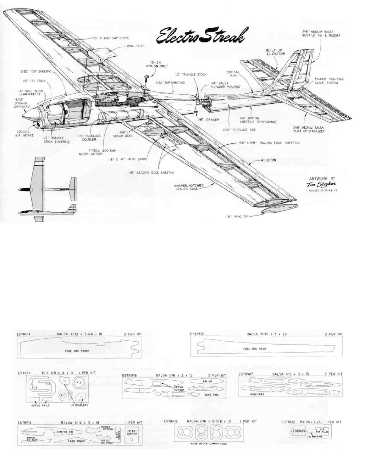
Study the perspective drawing on page 5 to become
familiar with the parts of the ElectroStreak
4
Page 5
GET READY TO BUILD
D 1. Unroll the plan sheet. Re-roll it inside out to make it lie
flat. NOTE: If you have a small work area, you may cut the plan
into two sections, "wing" and "fuselage".
D 2. Remove all parts from the box. As you do, figure out the
name of each part by comparing it with the plans and the parts list.
Using a felt tip pen, write the part name or size on each piece to
avoid confusion later. Use the die-cut patterns shown below to
identify the die-cut parts and mark them before punching out. Save
DIE PATTERNS
all scraps. If any of the die-cutparts are difficult to punch out, do not
force them! Instead, first cut around the parts with an Xacto knife.
NOTE: After punching out the die-cut parts, use your T-Bar or
sanding block to lightly sand the edges to remove any die-cutting
irregularities.
D 3. As you identify and mark the parts, separate them into
groups, such as fuse (fuselage), wing, fin & stab (stabilizer), and
hardware.
5
Page 6
FUSELAGE
PREPARE FUSELAGE SIDES
D 1. Lay a 6" x 6" piece of waxed paper on the plan
in the area where the front and rear fuse sides join, to
protect the plan.
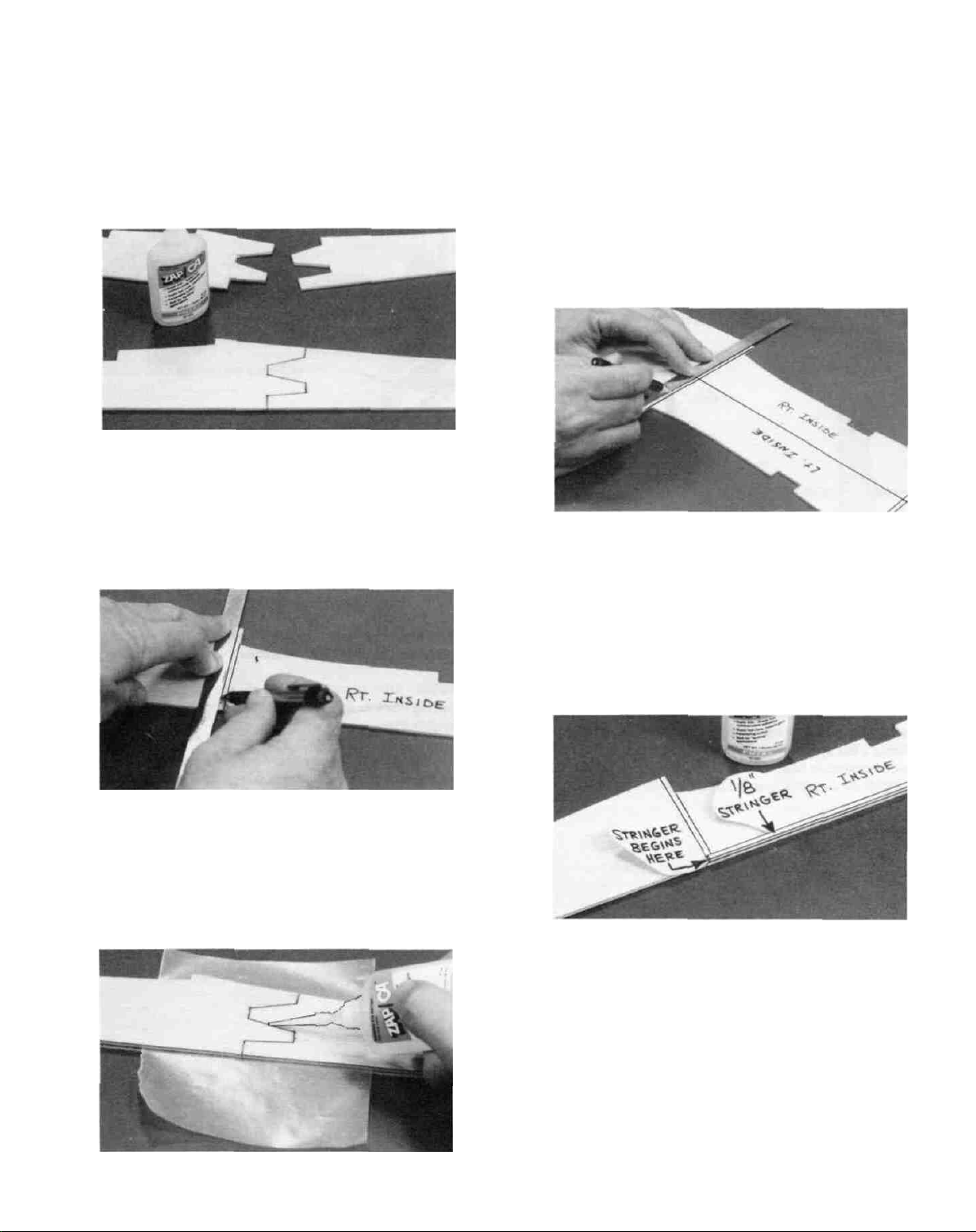
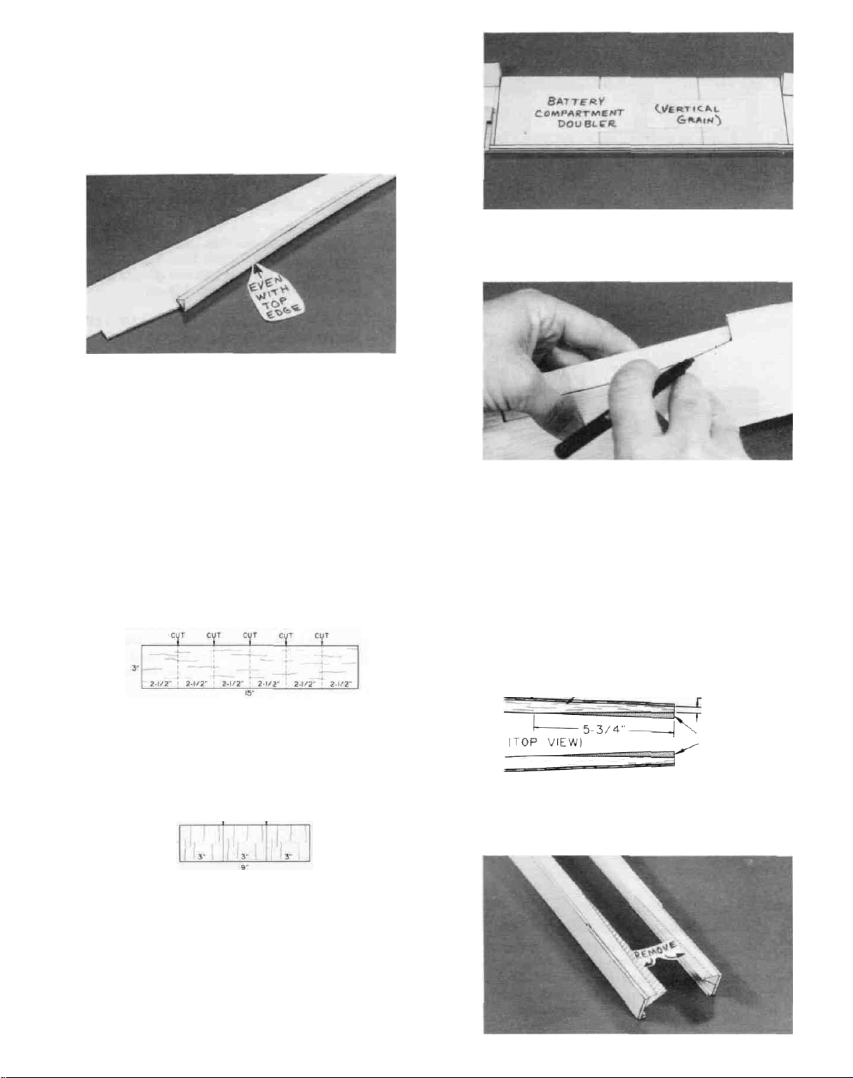
D 2. Lay a die-cut 3/32" balsa fuse side front and fuse
side rear on the plan and carefully line them up along the
bottom edge. Apply thin CA glue to the joint, then apply
thick CA glue to fill any gaps. Sand the joint smooth using
a T-bar sander with 100-grit sandpaper.
of waxed paper between the fuse sides to prevent gluing
them together. Sand the Lt. fuse side joint smooth.
D 5. Remove the waxed paper, put the two fuse sides
together and line them up at the front and the bottom
edges. Then check to make sure they are exactly the same
all the way around. Sand the edges as necessary until the
two fuse sides match. It is especially important that the
overall length be the same. so sand the tail end as necessary.
D 6. Lay the two fuse sides flat on the table, with the
straight portion of the bottom edges touching at the front
half. Then, using a straightedge and a pen, extend the
former location lines onto the fuse side that does not have
them. Also, mark the 2nd. fuse side, "Lt. inside".
D 3. While the fuse side is still in place on the plan,
use a straightedge and a pen to mark the locations of
formers F-3 and F-4 only. Note that we have extended the
former lines above and below the fuse for your convenience. Mark this fuse side "Rt. Inside".
D 4. Glue the left fuse side halves together by care-
fully positioning them on the right fuse side. Use a piece
D 7. Glue the 1/8" x 1/8" x 30" balsa stringers to the
inside of the fuse sides, along the bottom. The stringers
begin at the front edge of F-3. Trim the stringers even with
the aft end of the fuse sides.
LANDING GEAR NOTE: If you have decided to install a landing
gear, you will now install the Lt. & Rt. LG Doublers. However.
even if you do not plan to use a landing gear, you may wish to install
these doublers anyway, in case you change your mind later. (The
extra fuselage parts required for the LG will add 1/4 oz.).
6
Page 7
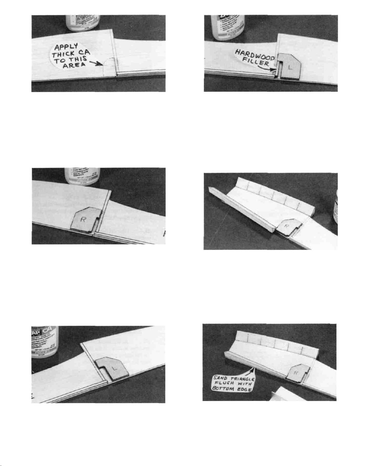
D 8. Strengthen the inside surface of the fuse sides in
the area of the LG wires by applying thick CA and spreading
it smooth with waxed paper.
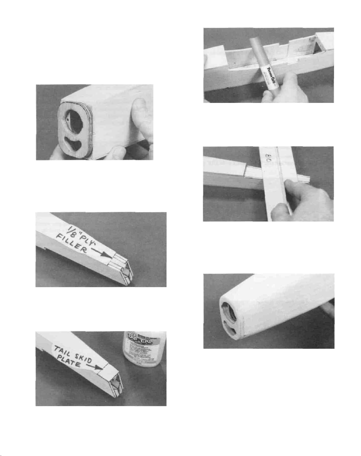
D 11. Glue the 1 /8" x 1 /8" x 7/8 " hardwood filler to the
Lt. fuse side, along the front edge of F-3. NOTE: The
bottom end of this filler must be 1/16" above the bottom edge
of the fuse side, and there must be a 1/8" gap between the
filler and the LG doubler for the LG wire.
D 12. Using a razor saw, cut one of the 1/2" x 24" balsa
triangles into two 6-1/8" lengths and two 5-7/8" lengths.
D 9. Glue the die-cut 1/8" ply Rt. LG doubler to the Rt.
fuse side. The bottom edge of the doubler is even with the
bottom of the fuse side, and there must be a 1/8" gap in front
of F-3.
D 10. Glue the die-cut 1/8" ply Lt. LG doubler to the Lt.
fuse side. The bottom edge of the doubler is even with the
bottom of the fuse side, and there must be a 1/4" gap in front
of
F-3.
D 13. Glue the 5-7/8" long triangles to the inside of the
fuse sides along the bottom, from the front of F-3 forward to
the front of the fuse sides. Note that the triangle is angled
in relation to the bottom edge of the fuse side (see the fuse
plan side view). NOTE: If you have installed the 1/8" ply
LG doublers, run the triangles from the front of the doublers
forward.
D 14. Using your razor saw, cut slots in the 6-1/8"
lengths of 1/2" triangle, to permit bending. Then glue these
triangles to the fuse sides along the top edge, beginning at the
rear edge of F-3 and extending forward to the front of the
fuse sides.
(See
Steps
l5
and 16
at
the top of page
8.)
7
Page 8
D 15. Trim and sand the balsa triangles even with the
front of the fuse sides.
D 16. Sand off the bottom triangles even with the bottom
edge of the fuse sides.
D 17. Glue the remaining two 1/2" x 24" balsa triangles
to the fuse sides along the top edge, beginning at the front
edge of F-4, and extending to the aft end of the fuselage.
NOTE: Sand the front end of the balsa triangles to an angle
so they line up with the front edge of F-4. NOTE: The
triangles extend into the stabilizer saddle area and will later
be sanded even with the stab saddle.
D 18. Trim and sand the balsa triangles even with the aft
end of the fuse sides.
D 23. Trim the ends of the battery compartment doubler
to fit between the rear of F-3 and the front of F-4.
D 24. Mark the outline of the wing saddle on the battery
compartment doubler, then trim the doubler to this outline
using an Xacto knife.
D 19. Find the two 1/16" x 3" x 15" balsa sheets. Select
the sheet that has the softest balsa, and use it in the next steps.
D 20. Using an Xacto knife and a straightedge, cut the
1/16" x 3" x 15" balsa sheet into 6 pieces, each having a length
of 2-l/2".
D 21. Edge glue three of these pieces together to make
the battery compartment doubler.
GLUE GLUE
2-1/2-
D 22. Sand smooth, and sand one long edge straight,
using your T-bar.
D 25. Glue the doubler to the fuse side in the following
manner: apply thick CA to the doubler, press the doubler in
place, then apply thin CA around the edges.
D 26. Repeat steps 21-25 to make and install the other
battery compartment doubler.
-FUSE SIDE
—1/2" TRIANGLE
1/4"
REMOVE THIS
PORTION
D 27. At the aft ends of the fuse sides, sand the triangles
to a taper as shown in the sketch and photo. This will enable
the tail end to be pulled together and will provide a strong
base for the stabilizer and fin.
8
Page 9
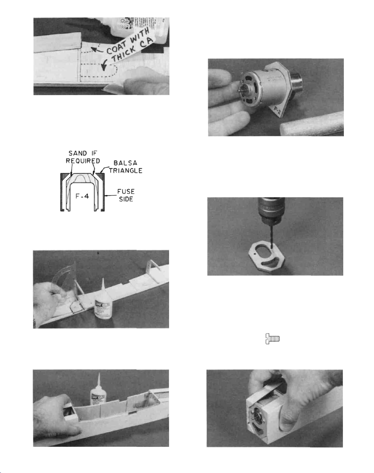
D 28. Spread a couple drops of thick CA on the battery
compartment doublers in the area of the servo rails and wing
hold-down plate. Use a piece of waxed paper to spread it
smooth.
view, working on a flat surface and glue the Lt. fuse side to
F-3 and F-4. NOTE: The bottom edges of the fuse sides
must be down on the flat surface during this step.
ASSEMBLE FUSELAGE
D 1. Trial fit the die-cut 1/8" ply formers F-3 and F-4.
You may have to sand the top comers slightly to make the
formers fit perfectly. (Remove only a very small amount at
a time).
D
4.
Trial
fity our electric
motor
through the hole in
F-
2. Sand the hole as necessary for a snug fit (Use a piece of
sandpaper wrapped around a dowel). NOTE: If the motor
label gives you problems when fitting, you may want to peel
off the label.
D 5. Note that we have punched the locations of the two
screw holes in F-l. Drill 1/8" holes at these two locations.
Be sure to use a wood backing when drilling to prevent
damaging the part you are drilling.
D 6. Mount F-1 onto the front of the motor with the two
M3 x 6 metric screws.
D 2. Glue F-3 and F-4 to the Rt. fuse side. Use a square
to make sure these formers are installed at right angles
(perpendicular) to the fuse side.
D 3. Place the fuselage upright on the fuselage top
M3x6 SCREW
D 7. With F-1 mounted to the motor and F-2 positioned
9
Page 10
on the motor as shown in the fuse plan side view, trial fit this
assembly into the front of the fuse. Pull the fuse sides
together over the formers and note the fit. If it is necessary
to sand the comers of F-1 for a perfect fit, you must also sand
the top comers of F-2 an equal amount, to maintain the
correct down-thrust angle. NOTE: Remove the formers
from the motor while sanding, to avoid getting pieces of
wood inside the motor. NOTE: When trial fitting, notice
that the right fuse side protrudes in front of F-1. This is
normal, due to the built-in right thrust. You will later sand
everything off even with the front of F-l.
D 8. Holding the motor, F-l and F-2 in place, glue F-l
and F-2 to the fuse sides with thin CA. (Do not glue the
motor to the formers!) Then remove the motor and
reinforce the glue joints by adding thick CA.
D 9. Align the front half of the fuse on the plan (top
view) and hold it down with weights.
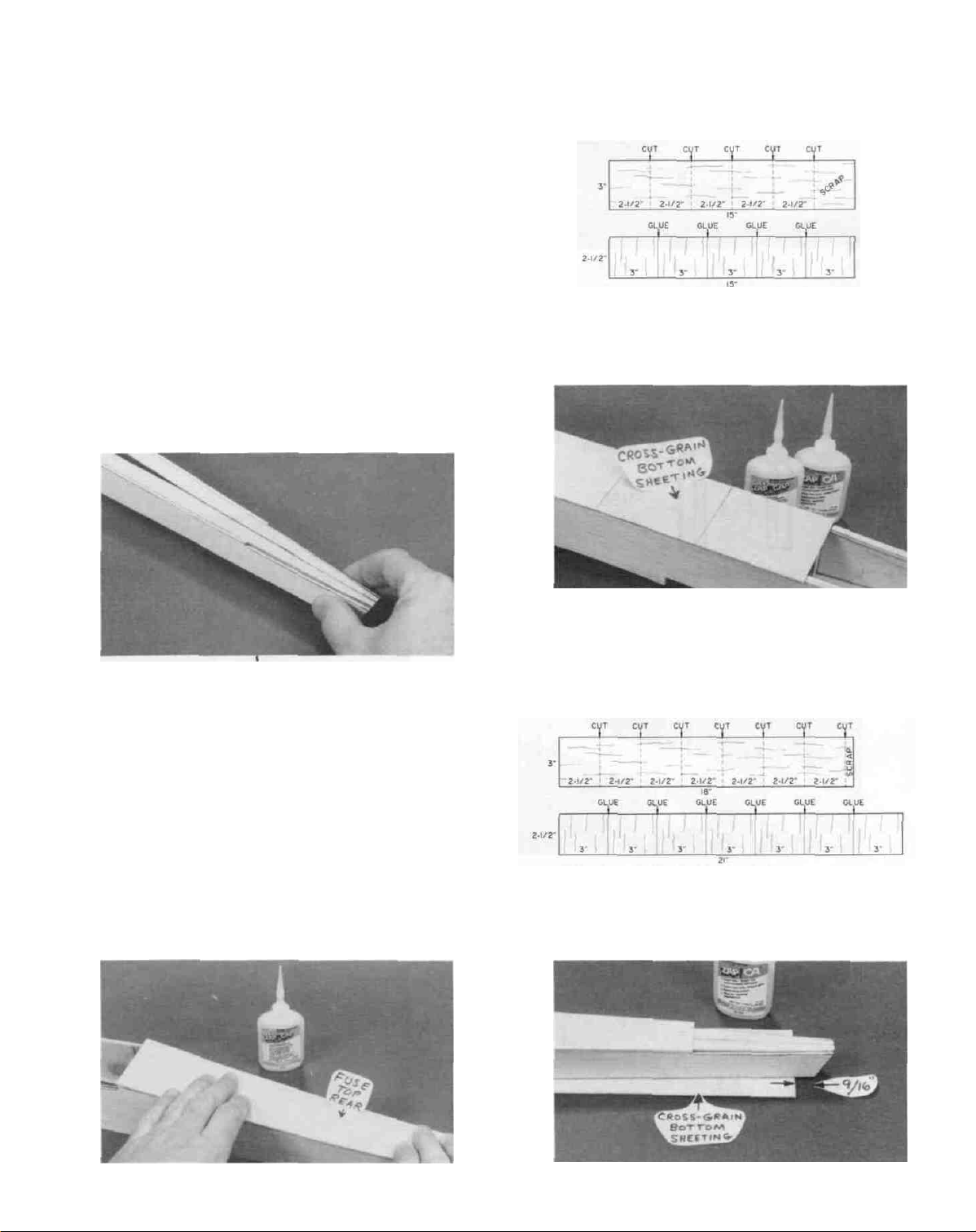
NOTE: This sheeting begins at the front of F-4 and ends at the front
of the stab saddle area (trim as necessary).
D 13. From the 1/16" x 3" x l5" hard balsa sheet, cut five
2-1/2" lengths. Edge glue these pieces together as shown.
Then sand smooth on both sides with your T-bar and 100-grit
sandpaper.
D 10. Pull the aft ends of the fuse sides together, align
with the plans, and glue the triangles together. NOTE: If,
when pulling the fuse sides together, you notice that one side
seems stiff er than the other, you may make a few vertical cuts
in the triangle on the stiff side to "soften" it up and allow it
to bend to the same curvature as the other side.
D 11. Using a T-bar or sanding block, sand the top edges
of formers F-l, F-2, F-3 and F-4 even with the top of the balsa
triangle stringers. Also sand the top of the triangle stringers
even with the top edge of the fuse sides, and to remove any
rough glue joints.
D 14. Glue this sheeting to the bottom of the fuse,
beginning at the front of F-l.
D 15. From one of the 1/16" x 3" x 18" soft balsa sheets
(the other two are used in the wing), cut seven 2-1/2" lengths.
Edge glue these pieces together as shown.
Then sand smooth on both sides with your T-bar and 100-grit
sandpaper.
D 12. Glue the 3/32" balsa top rear sheeting in place.
D 16. Glue this sheeting to the bottom of the fuse from
10
Page 11
F-4 to the aft end. NOTE: If you are planning to install the
landing gear,do not sheet the aft 9/16" of the fuse bottom.
D 17. Trim and sand the cross-grain bottom sheeting
even with the fuse sides.
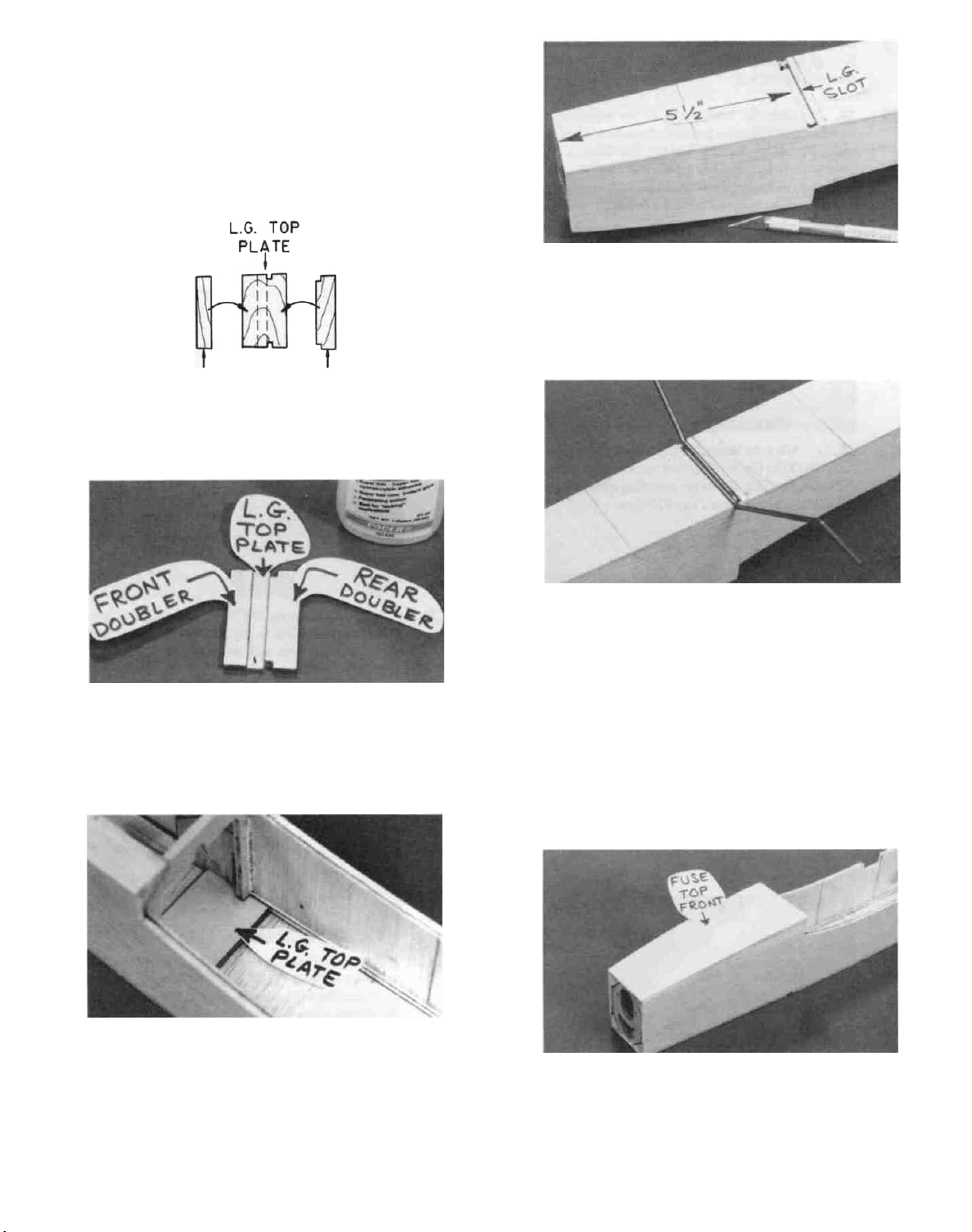
D 20. Cut a 1/4" wide slot in the bottom sheeting for the
landing gear. NOTE: This slot is approximately 5-1/2 to 5-
3/4" back from the front of F-1. You may push a pin through
the bottom sheeting in a few places to "find" the correct slot
location before cutting.
FRONT
DOUBLER
REAR
DOUBLER
D 18. If you are installing a landing gear, glue the die-cut
1/16" ply front and rear LG doublers to the 1/16" ply LG
top plate.
D 21. Trial fit the 1/8" wire landing gear wires into the
LG slot. File the slot as necessary for a good fit.
D 22. At this time, before you close up the front of the
fuse, make a final check of the motor fit through F-2. You
should be able to readily slide the motor into place from the
rear, but it should fit rather snugly. If the motor is loose in
F-2 it will result in a noisy vibration when the motor is
running. You can tighten it up by coating the inside hole in
F-2 with a thin layer of thick CA glue. If it is too tight, use
sandpaper wrapped around a dowel to enlarge the hole
slightly.
D 19. Trial fit the LG plate/doubler assembly in place in the
fuselage, sanding and filing as necessary for a good fit, then
glue in place. NOTE: The slot between the front and rear
LG doublers must be down.
D 23. Glue the 3/32" balsa top front sheeting in place.
NOTE: This piece has been cut slightly oversize to allow
extra for trimming.
11
Page 12
D 24. Sand all balsa parts flat and even with the front of
F-l. Also sand the rear edge of the fuse top front even with
the rear edge of F-3.
25. Glue the four layers of the balsa nose block
D
together, alternating the grain direction at each layer (you are
making balsa "plywood"). NOTE: Use thin CA to achieve
good penetration, making a hard and durable nose block.
After the glue has hardened, sand the inside of the openings
with sandpaper wrapped around a dowel.
D 26. Glue the laminated nose block to the front of the
fuse. NOTE: The layer having vertical grain should be in
the front. NOTE: If you are installing a landing gear (and
tail skid), perform steps 27 and 28 now.
SAND THE FUSELAGE
D 1. Carefully sand the vertical grain balsa battery
compartment doublers even with the fuse sides in the wing
saddle area.
D 27. Cut a scrap of 1/8 " ply (from die-cutting scrap) to
fit snugly between the 1/8" x 1/8" balsa stringers at the aft
end of the fuse. Glue in place.
D 28. Glue the die-cut 1/16" ply tail skid plate to the
bottom of the fuse at the aft end. Then sand the tail skid parts
even with the fuse sides and fuse tail end.
12
2. Note that the 1/2" balsa triangle stringers protrude
D
above the fuse sides in the stab saddle area. Sand these
triangles down even with the fuse sides in the stab saddle
area.
3. Study the cross-section drawings of the formers
D
and cross-sections "E-E" and "F-F" to get a "feel" for how
much sanding will have to be done on the fuselage to produce
the correct shapes. Now use a sanding block with coarse
(#50 or #80 grit) sandpaper to sand the fuselage to its
approximately final shape.
4. Change to progressively finer grades of sandpaper
D
to achieve the final shape and smoothness. If you cut a long,
narrow strip (1" x 10") of 400-grit sandpaper and use it like
a "shoe-shine cloth" on the top of the fuse, you will be
surprised at the uniformity and smoothness that can be
achieved.
Page 13

D 5. At this time, you should check the basic fuselage
weight. It should weight approximately 2-1/2 oz. with the
ply LG plates installed. If the fuse weighs closer to 3 oz., go
over the entire fuse with sandpaper another time or two to
reduce weight, especially on the top and front.
TEMPORARILY MOUNT LANDING GEAR
D 1. Place the 1/8" wire main landing gear in position.
NYLON L.G. STRAP
2. While holding two of the nylon landing gear
D
straps in place, mark the locations of the holes to be drilled.
Drill 1/16" pilot holes at these locations. NOTE: Use only
two of the landing gear straps (the others are extras).
CUT FIN SLOT IN FUSE TOP
D 1. From the front of the stab saddle area, measure
forward and make marks on the fuse top at 1 -3/16" and
1-11/16".
2. Between the above marks, cut a 3/16" wide slot in
D
the exact center of the fuselage top, using an Xacto knife.
INSTALL RUDDER CABLE GUIDES
D 3. Secure the nylon straps with #2 x 3/8" screws.
#2x3/8"
SCREW
DRILL HOLE FOR TAIL SKID
D 1. Drill a 1/16" hole in the plywood tail skid plate,
drilling at an angle, as shown on the plan.
D 2. Trial fit the 1/16" wire tail skid.
D 3. Now remove the main gear and tail skid (they will
be permanently attached after covering).
13
1. Measure 1"
D
forward
from
the front edge of the stab
saddle, and make a mark on the fuse top. Then make marks
1/4" Rt. and Lt. from the fuse centerline.
2. Drill 1/8" holes* at the above two marks for the
D
rudder cable guides. NOTE: You must hold the drill at a
very "flat" angle, as shown on the plans. *NOTE: For
cleaner holes, you may drill these holes with a 1/8" diameter
brass tube that has been sharpened by running an Xacto knife
around the inside of one end.
3.
D
Insert the
1/8"
diameter
plastic
rudder
tube into one of the holes you just drilled. Looking through
the opening in the aft end of the fuse, insert the tube until it
cable
guide
Page 14

just protrudes into the inside of the fuse. Then mark the tube
on the outside (allowing 1/4" extra) and cut it off. Repeat for
the other side.
D 4. With the cable guide tubes in place, apply thin CA
where they enter the fuse.
D 5. Cut and sand the tubes off even with the surface of
the fuse top.
INSTALL SERVO RAILS
NOTE: The plans and photos show installation of Futaba S-33
servos. If you are using a different type servo you may have to
modify the servo rails and installation procedure.
1. While you can still easily reach through F-4, place
D
a few drops of thick CA on the fuse bottom in the receiver
area and smooth it out with a piece of waxed paper. This
Strengthens the balsa in the area where the receiver will be
fastened with Velcro.
5. Cut a heavy paper shim and lay it on the fuse
D
bottom, under the servos (to prevent the servos from touch-
ing the bottom). With the servos and rails in place, glue the
rails to the fuse sides and F-4 with thin CA. Remove the
servos after the glue has hardened.
2. Stick two servos together with the square of
D
double-stick tape. NOTE: Make sure the servos are
positioned as shown on the plan.
D 3. Install the servo grommets and eyelets, and mount
the servos to the die-cut 1/8" ply servo rails using the screws
provided with your radio.
D 6. Cut 1/4" balsa triangles to fit under the servo rails.
Glue in place. Add thick CA as necessary for secure glue
joints.
INSTALL WING PLATE
D 1. Find the 1/8" x 1/2" x 2-1/16" birch ply wing plate
and sand it as necessary to fit snugly between the fuse sides.
D 2. Position the wing plate exactly as shown on the
plan and glue it in place.
D 4. Sand the servo rails a little at a time until the
servo/rail assembly fits snugly between the fuse sides at the
front of F-4.
D 3. Build up fillets of thick CA or epoxy all around the
wing plate, on top and bottom, to securely lock it in place.
NOTE: This installation must be very strong!
14
Page 15

FIN AND STABILIZER
BUILD THE FIN AND RUDDER
1. Find the following parts: Six 3/16" x 3/8" x 18"
D
balsa sticks, and the die-cut 3/16" balsa rudder bottom and
dorsal fin pieces. Lightly sand the edges of the die-cut
pieces with a sanding block to straighten out any die-cutting
irregularities. Select the two straightest 3/16" x 3/8" x 24"
balsa sticks and set them aside for later use as the stab
trailing edge and the elevator leading edge.
D 2. Working over the separate FIN drawing on the
plan, mark and cut the balsa sticks for the outer framework
of the fin and rudder. Hold or pin the parts over the plan and
glue the outer framework together with thin CA, working on
waxed paper to prevent gluing to the plan.
D 3. Cut the 3/16" x 3/8" balsa ribs to fit between the
leading and trailing edges of the fin and rudder, and glue
them in place.
2. Tape a piece of waxed paper over the separate
D
STABILIZER drawing on the plan, then lay the die-cut
3/16" balsa stab center pieces on the plan and pin in place.
NOTE: These die-cut pieces may have irregular edges, so
you should sand the edges with your T-bar first, until they fit
the plan exactly. Edge glue these stab centerpieces together
with thin CA.
3. From 3/16" x 3/8" balsa sticks, cut the outer
D
framework pieces and glue them together. Note: The
straightest 3/16" x 3/8" balsa stick should be used for the
trailing edge.
4. Cut the stabilizer ribs from the 3/16" x 3/8" balsa
D
sticks and glue them in place.
5. Sand both sides of the elevator smooth with your
D
T-bar, then sand the stabilizer leading edge and ends to a
rounded shape as shown on the plan.
6. In the same manner, working over the plan, build
D
the elevator.
7. Draw a centerline on the stab TE and elevator LE.
D
D 4. Glue the die-cut 3/16" balsa dorsal fin parts
together over the plan, to make the dorsal fin.
D 5. Sand both sides of the fin, rudder and dorsal fin
smooth using your T-bar and 100-grit sandpaper. Draw a
centerline on the fin trailing edge and the rudder leading
edge. Sand the leading edge of the fin to a rounded shape
(except in the area where the dorsal fin will attach). Sand the
leading edge of the rudder to a "V-shape (as shown on the
plan).
D 6. Using your sanding block, sand the rudder to a
taper, as shown in the detail drawing on the plan.
BUILD THE STABILIZER AND ELEVATOR
D 1. Get the following parts together: Die-cut 3/16"
balsa stab and elevator center pieces, two 3/16" x 3/16" x
17" balsa sticks, and the remaining 3/16" x 3/8" balsa sticks.
8. Sand the elevator leading edge to a V-shape as
D
shown on the plan.
9. Sand the elevator to a taper, as shown on the plan.
D
MAKE THE HINGES
D 1. You'll need the following: The 7" length of hinge
strip material, a piece of 220 grit sandpaper, a ruler, scissors
and a 1/16" drill.
2. Take the strip of hinge material and roughen both
D
sides with 220 grit sandpaper. This is best done with a small
15
Page 16

piece of sandpaper held with your fingers, rather than a
sanding block. Do not sand the centerline of the hinge
material.
3. Using a ruler and a ball point pen, draw lines
D
dividing the hinge material into sixteen 3/8"-wide segments.
o
o
3/8"
HINGE
0
0
TEMPORARILY INSTALL HINGES (Do not glue the hinges at
this time).
1. You'll need eight of the hinges you just made, plus
D
an Xacto knife with a No. 11 blade.
2. If you have not already done so, draw an accurate
D
centerline on the trailing edge of the fin and stabilizer.
4. Drill four 1/16" holes in each of the hinge seg-
D
ments as shown on the plan. Use a wood block as a backing
when drilling these holes. After drilling, lightly sand the
hinges again to remove any rough edges caused by drilling.
D 5. Fold the hinge material back and forth a few times
to "condition" the hinges.
6. Cut the hinges apart with a scissors on the lines
D
you previously drew. Also snip off a small piece of each
comer.
(See sketch at top of next column.)
3. Lay the fin and stabilizer on the plan and mark the
D
hinge locations on the trailing edges.
4. Now, while holding the elevators in place against
D
the stabilizer trailing edge, transfer the hinge locations over
to the elevator leading edge. Repeat this process to mark
the hinge locations on the rudder.
NOTE: The hinges supplied with this kit are thin enough that they
can be inserted into a slot made with an Xacto knife. Most other
hinges require you to use a hinge slotting tool. The following steps
describe how to easily cut the hinge slots with an Xacto knife.
CAUTION!!!: You must use extreme care when cutting hinge
slots with an Xacto knife, to avoid cutting yourself! If the
balsa part breaks while you are pushing on the knife, the blade
could go into your hand before you know it! A good precaution is to wear leather gloves while performing the following
steps.
16
Page 17

5. Begin by carefully cutting a very shallow silt in
D
the fin trailing edge at the hinge location. This first cut is to
establish your cut in the right place, so concentrate on
staying on the centerline and don't cut too deep!
6. Make three or four more cuts in the same line,
D
going slightly deeper each time. As you make these
additional cuts. work on going straight into the wood.
1. You'll need three nylon control horns, two 2-56
D
x 3/8" screws, two 2-56 x 5/8" screws, two 2-56 hex nuts, a
3/32" drill, a small screwdriver and a pliers.
2. While holding two nylon horns together at their
D
bases, drill 3/32" holes through the holes in one horn,
making two new holes in the other horn. The purpose of this
is to enable the horns to be bolted together on both sides of
the rudder.
7. After you have cut about halfway into the wood,
D
you can push the blade all the way through, while "wiggling" the knife handle back and forth. Continue to pivot the
knife while moving the blade to both ends of the hinge
location.
8. Trial fit the hinge into the slot. If the hinge is
D
difficult to push in, re-insert the knife and move it back and
forth in the slot a few times to enlarge the slot.
9. Repeat the above process to cut slots at all the
D
hinge locations in the fin, rudder, stabilizer and elevators.
10. Assemble the rudder to the fin and the elevators to
D
the stabilizer (DO NOT GLUE), and check the operation of
the hinges.
TEMPORARILY MOUNT CONTROL HORNS
2-56x5/8" SCREW
2-56 x 3/8" SCREW
NYLON HORN AND NUT PLATE
D 3. Cut and sand the two nylon rudder control horns to
the shape as shown in the "Rudder Detail" drawing on the
plan.
4. Lay the rudder on the fuselage plan side view and
D
determine where the nylon control horn should be located.
Holding the nylon horn with only two holes on the left side
of the rudder, use a pencil to mark through both holes in the
horn.
17
Page 18

D 5. Start pilot holes with a pin at the marked locations,
then drill the holes with a 3/32" drill.
MOUNT THE STABILIZER
D 1. Accurately measure and mark the exact center of
the fuselage top at F-4. Also measure the width of the
stabilizer and mark the exact center at the trailing edge.
D 2. Place the fuselage on a flat surface, and hold it
down firmly with a book or other heavy object.
3. Position the stab on the stab saddle, centered side-
D
to-side, and pin it in place.
D
6.
Trial mount the rudderhorns with two2-56 x 5/8"
screws and hex nuts.
7. In a similar manner, temporarily mount the eleva-
D
tor control horn on the elevator. NOTE: When marking
the locations for drilling, you must hold the nylon horn
on the BOTTOM of the elevator! Use the 2-56 x 3/8"
screws and nylon nutplate to mount the elevator horn. IM-
PORTANT; Make sure the nutplate and screws of the
elevator horn do not touch the rudder when the elevator is
deflected up 1/2" Sand the bottom of the rudder if necessary
to eliminate this possibility.
18
4. While holding the stab firmly in place onto the
D
saddle, measure down to the flat work surface from both
ends of the slab. If one side is higher than the other, sand the
high side of the stab saddle with your T-bar sander and 100
grit sandpaper (Sand only a little at a time!). Replace the
stab in the saddle and re-check the measurements. Continue
this process until the stab is level within 1/16".
5. Again, pin the stab to the stab saddle, and measure
D
from the rear corners of the stab to the center mark at F-4.
Adjust the position of the stab until these measurements are
equal.
Page 19

D 6. Glue the stab to the stab saddle by applying thin
CA generously along both sides of the fuse. Also apply thin
CA in the fin notch and at the front and back of the stab to
insure that the glue fully penetrates into the joint. Finally,
add a small fillet of thick CA along both sides of the fuse/
stab joint to fill any gaps.
MOUNT THE FIN
IMPORTANT NOTE: Improper fin alignment is one of the most
common causes of poor flying airplanes. The fin absolutely must
line up with the centerline of the airplane! Therefore, use care in
the following steps to mount the fin properly.
1. Remember the fuselage centerline mark you made
D
at F-4? Now measure 3/32" left and right of that mark and
make two more reference marks. Now lay a straightedge
along the left side of the fin, with one end of the straightedge
on the left mark at F-4. Adjust the position of the fin until
it matches the straightedge.
D 3. Hold the fin in place on the stabilizer and line it up
with the marks you just made. Check to make sure the fin
is perpendicular to the stab, using a draftsman's triangle or
a carpenter's square. Apply a couple drops of thin CA to
tack glue the fin in place.
D 4. Double check the fin alignment (It must line up
with the fuselage centerline), then apply thin CA all along
the base of the fin. Use thick CA to fill any gaps.
5. Cut the die-cut "bumps" off the dorsal fin parts.
D
6. Sand the top edge of the dorsal fin to a rounded
D
shape.
D 2. Holding the fin in this position, draw lines on the stab
center on both sides of the fin for future reference. Double D
check this by laying the straightedge along the right side of
the fin and holding it on the right mark on F-4.
7. Align the dorsal fin on the fuselage centerline in
the same manner as used for aligning the fin. and glue it to
the fuse top and fin.
THIS COMPLETES THE BASIC FUSELAGE ASSEMBLY
19
Page 20

WING
BUILD THE WING PANELS
NOTE: It will be helpful to build the wing on a piece of "Celotex"
or other semi-soft (and flat) surface, into which you may easily stick
pins to firmly hold down the wing parts while building, to avoid
warps.
D 4. Before using the 1/8" x 1/4" x 23" hard balsa
spars, examine them carefully for possible imperfections.
Look for knots, soft spots, diagonal grain and any other imperfections. If possible, position each spar so the imperfections (if any) are on the outer half of the wing panel (toward
the tip), where they will be least affected by high stress. If
the spars are warped slightly, try to "balance them out" by
installing the warped spars in opposite directions (see
sketch).
D 1. Turn the plan around so the wing drawing is facing
you. Tape the plan to your flat work surface, and cover the
wing drawing with waxed paper (so you won't glue the wing
to the plan!). NOTE; If your work space is limited, you may
cut the left and right wing half drawings apart.
D 2. The shaped and notched wing leading edges (L.E.)
and trailing edges (T.E.) are fastened together by thin layers
of balsa. Separate them by folding until the balsa breaks.
Sand away the excess balsa that remains along the edges after
breaking them apart, using a T-bar with 100-grit sandpaper.
D 3. Before using the L.E. and T.E. pieces, you must
determine which pieces are to be used for the wing panel you
are building. Here's how;
A. Compare the leading and trailing edges with the
following drawings to determine the top and bottom of each
piece.
TOP TOP
TWO WARPED SPARS INSTALLED
THIS WAY WILL RESULT IN A
STRAIGHT WING
TWO WARPED SPARS INSTALLED
THIS WAY WILL RESULT IN A
WARPED WING
If you find that the spars in your kit are not satisfactory (due to gross imperfections, damage, or extreme
warp), just give us a call or write a note requesting replacements (see the "INTRODUCTION" on the first pages of this
book).
D 5. Carefully punch out all the die-cut 1/16" balsa
wing ribs. Sand the edges slightly to remove any die-cutting
irregularities.
D D 6. Pin one of the 1/8" x 1/4" x 23" spars to the plan.
NOTE: The spars are slightly longer than necessary, and
will be trimmed later.
LE.
T.E.
B. Notice that there are three notches near one end
of each piece that are 1-7/8" apart. This is the end that goes
toward the center (root) of the wing.
C. Take one of the LE pieces and lay it on the right
wing panel plan with the top up. If the three closely-spaced
notches are toward the center of the wing, you have the
correct LE for the right panel.
D. Do the same thing to determine which TE piece
to
use.
D D 7. Set rib W-l in place on the plan, holding it perpen-
dicular to the surface, and glue it to the spar.
20
Page 21

D D 8. Set rib W-8 in place, but do not glue to the spar.
Now glue the notched balsa TE to the aft ends of ribs W-1 and
W-8.
D D 9. Glue the shaped, notched balsa LE to the front of
ribs W-l and W-8. NOTE: Position the leading edge as
shown here:
CENTER L.E.
VERTICALLY ON
FRONT OF RIBS
L.E.
D D 10. Glue W-8 to the spar.
D D 13. From the 1/16" x 1-1/16" x 15" balsa sheet, cut
pieces to fit between ribs W-l and W-2, W-2 and W-3. and
W-3 and W-4. Glue these horizontal grain shear webs to
the front of the spars. (Cut each piece slightly oversize, then
sand to fit). Trim the webs even with the top of the top spar.
NOTE: Because the horizontal grain webs act as spar
doublers, it is important that they fit snugly between the ribs,
and that they are also glued to the nbs.
D D
14.
From the 1/16" x 3-5/8" x 1-1/16" balsa pieces, cut
vertical grain shear webs to fit between the ribs. as shown
on the plan. NOTE: The vertical grain webs extend out to
rib W-6, and are glued to the rear of the spars. Sand the
webs even with the top of the spar.
D D 11. Set ribs W-2 through W-7 in place, inserting the
ribs into the notches. Center each rib vertically in the LE
notches. With the nbs fully down on the plan and all ribs
inserted into the LE and TE notches, apply thin CA to all
joints.
D
D
12.
Glue the
top
spar
in
place.
21
D D 15. Sand the tops of the ribs slightly, to match the
trailing edge.
D D 16. Glue one of the 1/16" x 5/8" x 23" balsa trailing
edge sheets to the lop of the wing at the trailing edge.
NOTE: If this piece is warped slightly, just leave a little extra
sheeting hang over the TE, and trim it off later.
Page 22

D D
17.
Take one of the 1/16" x 3" x 24" balsa leading edge
sheets and cut it as shown (measurements are approximate)
to fit between the LE and the approximate spar centerline.
D D 18. Trial fit the top LE sheet, sanding as necessary for
a good fit at the LE.
D D 19. Glue the top LE sheet in place. Here is a suggested
method: Apply aliphatic resin glue (i.e. Titebond) or very
slow-setting CA glue to the tops of the ribs between the LE
and spars; lay the LE sheet in place and glue it to the LE with
thin CA; bend the sheeting down over the ribs and glue the
sheeting to the spars with thin CA.
D D 24. Using an Xacto knife, cut the "alignment feet"
off the ribs. Then use a T-bar or sanding block to carefully
sand the bottom of the ribs smooth, to blend with the TE.
D D 25. Examine all glue joints and re-glue if necessary.
D D 26. Using a razor saw, trim the spars, LE, TE and
sheeting even with ribs W-l and W-8.
D D 27.
D D 28. Glue the TE sheeting, LE sheeting, center section
D D 29. Trim the bottom sheeting even with ribs W-l and
Lightly sand the
using your T-bar and 100-grit sandpaper.
sheeting and cap strips to the bottom of the wing panel, in
the same manner as the lop (See Steps 16-22).
W-8, then sand the ends smooth and straight with your Tbar. Also sand the TE sheeting even with the TE.
bottom of the ribs and shear webs,
D D
20. From one of the
pieces to make the top center section sheeting (from W-l
to W-3). Glue the top center section sheeting to the ribs and
to the LE and TE sheeting.
D D 21. Mark the rib locations on the LE sheeting and TE
sheeting to aid in placement of the cap strips.
D D 22. From the 1/16" x 3/16" x 18" balsa sheets, cut cap
strips to fit on each remaining rib, from the LE sheeting to
the TE sheeting.
D D 23. Remove the wing panel from the plan and turn it
upside down.
1/16" x 3" x 18" balsa sheets, cut
D D 30. Glue the die-cut 1/16" balsa tip rib in place, and
sand to blend with the top and bottom of the wing.
D D 31. Fill any dings and cracks with lightweight balsa
filler, then sand the entire wing panel smooth, using your Tbar and 150-grit sandpaper. Observe how the leading edge
sheeting blends with the shaped leading edge. Sand the
leading edge as necessary to blend it in smoothly with the
top and bottom LE sheeting.
D 32. Repeat steps 6 through 31 to build the left wing
panel in the same manner.
22
Page 23

JOIN THE WING HALVES
1. Glue* the die-cut 3/16" balsa center rib to rib W-
D
1 of the left wing panel. (This center rib is slightly oversize
to allow for positioning). Then sand the center rib even with
the left wing panel.
*A thin layer of 5-minute epoxy or aliphatic resin glue is
recommended, to allow time for positioning.
D 5. Sand the flat area on the LE at the center, as shown
on the plan. As you are sanding, trial fit the wing in the wing
saddle. There should be approximately 1/32" to 1/16" "slop"
in the fit of the wing to the saddle, to allow for fiberglass and
covering.
FIBERGLASS CENTER JOINT
IMPORTANT: This wing does not use plywood dihedral
braces. Therefore, it is absolutely necessary to reinforce the
center of the wing by applying 2" -wide fiberglass cloth, top and
bottom.
NOTE: If you have previous experience with applying fiberglass,
feel free to use your favorite method, providing that it results in a
strong bond between the glass cloth and the wood. If this is your
first time, we offer the following suggested method, which is the
fastest and easiest we have seen.
2. Trial fit the two wing halves together by blocking
D
up both tips 3/16" (use the 3/16" x 3/16" x 4" blocks
provided) and the center at the trailing edge 7/16" (use the
"7/16" x 7/16" x 4" block provided).Use your T-bar to sand the
center rib to a slight angle, so the wing halves mate properly
at the center.
3. Place waxed paper under the center joint, then mix
D
up a batch of epoxy (or aliphatic resin may be used), and apply
a thin layer to the center rib. Push the two wing panels
together with both lips blocked up 3/16" and the trailing edge
up 7/16". Pin the wing halves together, carefully doublecheck alignment of the two halves, and allow the glue to fully
harden.
D 4. Sand the center joint smooth.
23
2"
1. Make location marks for the fiberglass reinforce-
D
ment cloth, 1-inch each way from the wing centerline.
2. Spray a very light mist of 3M "77" Spray Adhe-
D
sive on the center section in the area to be glassed. Hold the
spray can at least 12" away from the surface when doing
this to avoid a heavy buildup. The purpose of this is only to
give the wood a little "tackiness". If you apply loo much
spray it could result in a poor glue bond.
Page 24

D 3. Beginning at the trailing edge, lay the glass tape in D
place on the wing. Gently press the cloth in place, working
out all the wrinkles. The "77" spray adhesive should hold the
cloth down to the surface, but will permit you to lift and
reposition the cloth if you make a mistake. Keep working
forward along the top of the wing, around the leading edge,
and along the bottom of the wing, ending at the trailing edge. D
It is not necessary to wrap the glass cloth around the trailing
edge.
D 4. Working outdoors or in a very well-ventilated
area apply thin CA glue to the glass cloth. Begin by running
a bead of glue down the center of the glass cloth strip, then
continue applying the glue in lines until all the cloth has been D
secured. Run the thin CA out 1/4" beyond the edges of the
glass cloth to help protect the balsa sheeting when sanding
later. WARNING: This operation produces a larger than
normal quantity of CA fumes, so adequate ventilation is
a must!
D 5. Inspect the surface of the glass cloth. If any areas
are not glued down, apply a couple more drops of CA glue
and press down with a piece of waxed paper until the glue
sets.
D 6. To make sure the glass cloth is fully "wetted out"
and bonded to the balsa, you may apply more thin CA, a few
drops at a time, and spread it out with a piece of waxed paper.
2. Find the 3/16" diameter x 2-3/8" hardwood
dowel. Chamfer the ends slightly with sandpaper. Trial fit
the dowel in the hole, sanding slightly if necessary for a good
fit. Do not glue the dowel In place until after the wing has
been covered.
3. Lay some heavy paper in the wing saddle (to
simulate the foam wing seating tape which will be installed
later. Then trial fit the wing in the saddle. Sand the saddle
if necessary until the wing is level. You can check this by
standing behind the airplane and observing the position of
the wing in relation to the stabilizer.
4. Measure from the rear comers of both wing tips to
the fin TE, and adjust the position of the wing until the
measurements are equal. Holding the wing in this position,
make a reference mark on the wing TE in line with your fuse
centerline mark at F-4.
D 7. After the glue has set, trim the excess cloth at the
trailing edge with a sharp Xacto knife.
D 8. Carefully sand the edges of the glass cloth with a
T-bar sander with 80 or 100-grit sandpaper. Also, lightly
sand the surface of the glass cloth to remove any rough spots.
MOUNT WING TO FUSELAGE
D 1. Using an Xacto knife, cut away the fiberglass from
the wing dowel hole.
D 5. On the top of the wing, mark the location of the
hold-down bolt hole, 3/16" forward of the TE.
24
Page 25

D 6. Holding the wing firmly in its correct position,
drill a 5/32" hole down through the wing and plywood wing
plate. Try to hold the drill perpendicular to the top surface
of the wing, as shown on the plan.
D 7. Remove the wing from the fuselage and re-drill
the hole in the wing only, using a 13/64 (or 7/32") drill.
Apply thin CA to the inside of this hole (to harden the balsa),
the re-drill the hole after the glue has fully hardened.
block to fit the top of the wing.
D 3. Round the comers of the block to match the
fuselage.
D 4. Tack glue the fairing block in place with a couple
drops of CA. NOTE: Do not glue the wing to the saddle!
D 5. Remove the wing from the fuse, and securely glue
the fairing block to the wing. You may then use some lightweight balsa filler compound to fill any gaps and irregulari-
ties.
INSTALL AILERONS
D 8. Use a 10-24 tap to cut threads in the hole in the
plywood wing plate. Apply thin CA to the threads to harden
them, then re-tap the threads after the glue has fully hardened.
INSTALL WING FAIRING
10-24 NYLON BOLT
D 1. Place the wing in the saddle and install the 10-24
nylon bolt. (The heavy paper shim should be in place on the
saddle to simulate the foam wing seating tape).
NOTE; The ailerons are sawn (but not sanded), so you'll have to
sand off the saw marks using a T-bar with 80 or 100-grit sandpaper,
for a nice smooth finish.
D 1. Trim the ailerons to the length shown on the plan.
D 2. Draw a centerline on the leading edge of the
ailerons and the trailing edge of the wing.
D 3. Sand the leading edge of the ailerons to a "V"-
shape, as shown on the "WING CROSS-SECTION ATW-
1". Sand the trailing edge of the ailerons to a rounded shape.
D 4. Lay the wing on the plan and mark the hinge
locations on the wing TE.
D 2. Carve and sand the 3/8" x 2-3/8" x 2-3/8" balsa
D 5. Hold the ailerons against the TE, and transfer the
hinge marks over to the ailerons.
25
Page 26

D 6. Using an Xacto knife, cut the hinge slots in the
wing and ailerons.
D 7. Temporarily attach the ailerons to the wing with
the hinges, but do not glue until after the wing has been
covered!
INSTALL AILERON SERVO AND HORNS
NOTE: Install the aileron servo in the bottom of the wing!
D 1. Cut an opening in the fiberglass and bottom sheeting for
your servo. CAUTION: Do not cut into the wing spar or
shear webs!
D 2. Remove a sufficient portion of the center rib and
the W-1 ribs to fit your servo. NOTE: The die-cut openings
will have to be enlarged and deepened. (A Dremel Moto tool
with a 1/8" router bit is excellent for this, but it may also be
done with an Xacto knife and a long-nose pliers). The servo
must be installed as deep into the wing as possible.
D 4. Mount the servo using the screws provided with
your radio.
NOTE: Because the nylon horn mounting screws pass through the
inboard aileron hinges, we glued only these two hinges into the
ailerons (permanently), mounted the horns (temporarily), and
worked around these hinges when covering the ailerons. If you do
not want these hinges in the way when covering, we suggest that you
wait until the airplane is covered and the hinges glued in before
installing the nylon horns.
D 5. Hold the nylon horns on the bottom of the ailerons
in the locations shown on the plan, and mark the locations
of the mounting screws.
D 3. Make two servo rails from the 1/8" ply die-cutting
scrap, and glue in place. (See the side view of the aileron
servo installation on the plan).
D 6. Drill 5/32" holes through the ailerons (and
hinges). Put a drop of thin CA into each hole (to harden the
balsa), wait until the glue hardens, then re-drill the holes.
D 7. Temporarily mount the nylon homs with the 2-56
x 5/8" screws and nylon nutplates. You may cut off the
portion of the screws that protrude through the nutplates.
2-56x
5/8"
NYLON HORN AND NUT PLATE
26
SCREW
Page 27

COMPLETION
MAKE THE ELEVATOR PUSHROD
D 1. You'll need the following: 1/4" x 1/4" x 17-1/4"
balsa stick, 12" pushrod wire (threaded one end), nylon
clevis, and strong thread (not included).
NYLON CLEVIS
D 2. Clean the pushrod wire with alcohol or solvent to
remove all oils from the surface.
D 3. Draw a line 1 -inch long on both ends of the 1/4" x
1/4" x 17-1/4" balsa stick to mark the locations of the
pushrod wire grooves.
D 5. Drill 5/64" holes through the stick at the end of the
grooves you made in the above step.
D 6. Screw a nylon clevis on the threaded end of the
steel pushrod wire. Screw it all the way on, until the wire is
visible inside the clevis (about 17 full turns). Note: The
wire will be easier to hold if you grasp it with a pliers.
D 7. Lay the wire on the fuse plan (side view), and
notice where the wire makes a 90-degree bend and goes into
the stick and mark that location on the wire. Make this bend
now and cut off the excess wire.
D 4. Use the threaded end of one of the wire pushrods
to "file" grooves in the balsa stick where you drew the lines.
The depth of the grooves should be about 1/2 the thickness
of the wire.
D 8. Take the straight wire that you cut off and make a
short 90-degree bend in the end. Also notice the slight bend
near the midpoint of the wire (see plan).
D 9. Use sandpaper to roughen the ends of the wires
that will be glued into the balsa slicks.
27
Page 28

D 10. Insert the wires into the holes and slots in the
1/4" x 1/4" balsa stick and glue them in place with thin
CA.
D 3. Attach the nylon clevises to the nylon aileron
horns.
D 4. With the ailerons and the servo in the neutral
position, mark the pushrod wires where they cross the holes
in the servo arm.
D 5. Using a pliers, make a "Z"-bend in each of the
pushrod wires at the marks you just made, and cut off the
excess wire.
D 6. Work the pushrod wires into the holes in the servo
arm. NOTE: You may ha veto drill the servo arm holes with
a 5/64" drill bit. to fit the wires.
D 11. Use your T-bar to sand the ends of the balsa
pushrod to a rounded and somewhat pointed shape, as shown
on the plans and in the photos. This will reduce the chance
of the pushrod binding against something inside the fuselage.
D 12. Wrap the ends of the pushrod with strong thread,
as shown on the plan, apply thick CA to the threads and
smooth it out with a piece of waxed paper. Allow to harden.
MAKE THE AILERON PUSHRODS
D 1. Screw the nylon clevises onto both of the remain-
ing pushrod wires that are threaded on one end. Screw them
on all the way until the threads are protruding inside the
clevis.
D 2. Make the single bend in each pushrod as shown on
the wing plan.
PREDICT THE FINISHED FLYING WEIGHT
At this time you should try to accurately predict
what the final weight of your ElectroStreak will be. You are
shooting for a target weight of 40.5 ounces without landing
gear, or 42 ounces with landing gear, and using a 7-cell 1200
mAh motor battery. If it looks like your airplane will be only
1 ounce overweight, don't worry about it, as the flight performance will still be satisfactory. If, however, you predict
a final weight that will be 2 or 3 ounces overweight, you
should consider one or more of the following:
1. Give the entire airframe another good sanding.
Round the fuselage comers more, etc. Drill some 1/4" lightening holes in the landing gear plate and landing gear
doubler areas. You may be able to cut 1/2 oz. off the weight
by doing this.
2. Consider operating the plane without the land-
ing gear... a weight savings of 1-1/4 oz.
3. Consider covering the airplane with a very
lightweight covering film, such as "Black Baron Film" or
"Micafilm", and stay with a very simple trim scheme to
avoid excess weight.
4. Consider using a 7-cell 800 mAh motor battery,
which will provide good power and a weight savings of ap-
proximately 5 ounces; but will result in shorter flight times.
28
Page 29

Here is a sample weight computation: two strips at the front and rear). There is not enough Velcro
supplied in the kit to do this, but you may purchase more at
FUSELAGE (fuse, fin, stab, a sewing supply store or K-Mart. NOTE: We have found
rudder, elevator).........................................................3.5oz. the method shown on the plan to be satisfactory, but the
battery has come loose occasionally in hard landings and
WING (with ailerons and dowel)...............................4.5 oz. violent "negative G" maneuvers.
GOLDFIRE MOTOR (prop. adaptor)........................8.5 oz.
ELECTRONIC SPEED CONTROL
(or
servo
and
switch)..................................................2.1oz.
RADIO (receiver, switch, 3 micro be covered later in the manual.
servos, 225 mAh receiver battery)............................5.3 oz.
PUSHRODS AND ALL HARDWARE..................... 1.2 oz. a good time to balance the airplane laterally (side-to-side). Here is
7-CELL 1200 mAh MOTOR BATTERY................13.2 oz. D 1 Temporarily attach the wing and motor to the
COVERING
(Optional) WIRE LANDING GEAR. ler shaft and the bottom of the rudder. Do this several times.
WHEELS, COLLARS & HARDWARE...................1.5 oz.
TOTAL..................................................................423oz.
INSTALL
VELCRO
(film
type)...........................................2.5
heavy side, then you will have to add
——————— D 3. If one wing tip always drops when you lift, it
NOTE:
oz.
means
BALANCE THE AIRPLANE LATERALLY
Do not confuse this
"balancing the airplane fore and aft". That very important step will
Now that you have the basic airframe nearly completed, this is
how to do
D 2. With the wing level, lift the model by the propel-
it:
fuselage.
that
side
heavy wing panel and by drilling holes in the heavy wing tip.
If you are unable to balance it by removing material from the
wing tip until it balances. Place several drops of thick CA
on the inside surface of Rib W-8 until it balances.
procedure
is
heavy. Try to balance by sanding the
with
"checking
the
weight
C.G."
or
to the other
The receiver, receiver battery, motor battery and speed
control may all be attached to the fuselage using the self-adhesive
Velcro fastener strips supplied. Here are some tips:
D 1. Before attaching Velcro to balsa wood, spread a
few drops of thick CA on the balsa with a piece of waxed
paper to strengthen the balsa and to provide a good bonding
surface for the Velcro.
D 2. When applying Velcro to your electronic speed
control, do not apply it to the side that has the heatdissipating metal. Apply it to the plastic case on the side that
does not get hot during operation.
D 3. Do not attempt to cushion the radio or batteries by
using foam rubber. You must keep the fuselage interior open
to permit a free flow of cooling air for the motor and battery.
D 4. For additional security, you may run Velcro all
along the full length of the motor battery (instead of only
FINAL SANDING
D 1. Check the structure over carefully to make sure all
joints have been glued.
D 2. Fill all unwanted holes, dents and "dings" with
lightweight balsa filler (not the spackling compound found
in hardware stores).
D 3. Sand the entire structure smooth with 400 grit
sandpaper.
COVERING
D 1. Preparation: Before covering, make a final thor-
ough check to make sure the entire model has been sanded
smooth. The covering material probably will not hide imperfections in your structure, so now is the time to fix them.
Then vacuum the model dust free, using a brush attachment
on your vacuum cleaner. Finally vacuum your entire work
area dust-free. Remove the rudder, elevator, hinges, radio,
batteries, servos, pushrods, motor, switch harness and land-
ing gear from your model.
29
Page 30

2. Using any lightweight, good quality covering film
and following the manufacturer's instructions, cover your
model in the following sequence:
D 1. Rudder left side
D 2. Rudder right side
D 3. Elevator bottom
D 4. Elevator top
D 5. Cut 1/2" strips of covering, and apply to the joints
between the stab and fuse, the stab and fin, and the
dorsal fin and fuse.
D 6. Stab bottom
D 7. Stab top
D 8. Fin left side
D 9. Fin right side
D 10. Fuse bottom
D 11. Fuse sides
D 12. Fuse top
D 13. Wing tips (overlap slightly onto wing surface)
D 14. Bottom of wing (maybe done in one or two pieces)
D 15. Wing fairing
D 16. Top of wing (may be done in one or two pieces)
D 17. Bottom of ailerons
D 18. Top of ailerons
D 19. Now cut out the openings in the covering for the
rudder cable exits, radio switch, landing gear,
aileron servo and wing bolt.
NOTE: If you are not using a landing gear, you may install a strip
of protective plastic or a small nylon skid on the fuse bottom.
Although this is not usually necessary for belly landing on smooth
grass, it may help to avoid scuffing or tearing the covering material.
hinge, making sure it flows into the hinge slots. Be prepared
to wipe off any excess glue with a tissue. IMPORTANT:
When installing the hinges, make sure there is little or no
hinge gap. A large (1/32" or more) hinge gap will reduce
control surface effectiveness, and may promote flutter!
D 3. Re-install the nylon control horns. Cut off any
excess 2-56 screws that protrude through the nutplates.
IMPORTANT: Make sure the nutplate and screws of the elevator
horn do not touch the rudder when the elevator is deflected fully up!
Note: Photo shows uncovered structure.
D 4. Re-install the motor, wiring and all radio equip-
ment, including the radio on-off switch. NOTE: Depending on the radio you are using, it may be necessary to use
extra "aileron extension cords" from the receiver to the
speed control and from the switch to the receiver, due to the
aft location of the receiver.
ADD
TRIM
Add trim using covering film or self-adhesive trim
material or decals. NOTE: We recommend that you keep
your trim scheme as simple as possible for ease of application and to avoid weight build-up. We also recommend that
you trim with a contrasting color (light over dark, or dark
over light) for maximum visibility.
FINAL ASSEMBLY
INSTALL ALL COMPONENTS
D 1. Lay the rudder, elevators and ailerons on the plans
and mark on the leading edge of each part the locations of the
hinges. Now use a sharp Xacto knife to cut slits in the
covering at the hinge locations. Trial fit the hinges to make
sure you have "found" the slots which you previously cut. In
the same manner, slit the covering at the hinge locations in
the wing, stab and fin TE.
D 2. Glue the hinges in place. NOTE; We recommend
gluing the hinges with 30-minute epoxy (force glue into the
hinge slots with a plastic soda straw); however, we have also
had good success using thin CA glue. If you use thin CA,
assemble the parts first, then carefully apply the glue to the
Note: Photo shows uncovered structure.
D 5. Re-install the elevator and aileron pushrods.
D 6. Install the EZ Connector onto the elevator servo
arm as shown on the plan, and pass the elevator pushrod wire
through the EZ Connector. Install the slotted screw to
secure the elevator pushrod.
E-Z CONNECTOR
30
Page 31

Note: Photo shows uncovered structure.
D 7. Install the rudder cables. Pass the cables through
the crimp fittings as shown on the plan, and squeeze the fittings securely with a pliers. NOTE: When attempting to
run the cables from the rudder horns to the servos, it will help
to glue the end of the cable to a long piece of small diameter
music wire, then pull the cable through with the wire. Install
the EZ Connectors onto the rudder servo arms, and pass the
rudder cables through the EZ Connectors. Pull the cables
snug*, and secure them inside the EZ Connectors with 4-40
set screws, tightened down onto the cables. Pull on the
cables to check for slippage.
4-40 ALLEN
SETSCREW
•It is not necessary (or desireable) to pull the cables extremely tight, as this will cause excess friction and servo
wear. Just make sure all the slack has been taken up. Verify
this by grasping the rudder and moving it from side-to-side.
There must be no free-play in the rudder.
D 8. Apply 1/16" x 1/4" foam wing seating tape on
both sides of the wing saddle area to protect the wing.
D 9. Run the receiver antenna along the bottom inside
of the fuselage, and let the excess antenna length trail be-
hind.
D 11. Slide the propeller onto the prop hub, and secure
it with the aluminum spinner nut and the 6-32 socket head
cap screw. Tighten the cap screw with the hex key supplied,
but do not overtighten! ("Finger-Tight" not "WrenchTight" is a good rule of thumb).
6-32 SOCKET HEAD
CAP SCREW
NOTE: Although not included in this kit, you may use a 1-1/4"
plastic spinner for a sleeker appearance. If you use a spinner, you
may have to use a different length 6-32 socket head cap screw,
because of the thickness of the spinner backplate. CAUTION: If
you use a Goldberg Snap-On spinner, you must modify the snap lugs
so they insert more easily without damaging the motor.
D 12. (Optional) Install the main landing gear, using
the nylon straps and #2 x 3/8" screws provided. Drill the
wheel hubs if necessary to fit the main gear. Secure the
wheels with 1/8 "wheel collars. NOTE: A small drop of oil
on each axle will help the wheels turn freely.
D 13. (Optional) Roughen the 1/16" wire tail skid with
sandpaper, and clean it with alcohol. Glue the tail skid into
the hole you previously drilled, using CA glue or epoxy.
D 10. Install the 6-32 x 1/4" set screw in the aluminum
prop hub, then attach the prop hub to the motor shaft.
Tighten the set screw firmly down onto the "flat" on the
motor shaft using the hex key supplied. NOTE: When
installing the prop hub, it may be helpful to file the hex key
shorter, making it easier to use without touching the nose
block.
FILE OFF
THIS PORTION
6-32 SET SCREW
(See photo at the top of the next column.)
BALANCE YOUR MODEL
NOTE: This section If very important and must not be omitted!
D 1. With the wing attached to the fuselage, all parts of
the model installed. Including the 7-cell motor battery,
gently turn the model upside down.
D 2. Carefully measure 3.3/4" Inches (3.75") back
from the LE of the wing along both sides of the fuselage and
mark the location of the recommended balance point. Now
turn the model right side up.
D 3. Lift the model with your index fingers at the marks
you made at the recommended balance point (or for more
precision you may lift with the eraser end of two pencils).
If the tail drops when you lift, the model is "tail heavy" and
you must add weight to the nose to balance. If the nose drops.
it is "nose heavy" and you must add weight to the tail to
balance.
31
Page 32

NOTE: The forward limit of the balance range is 3/8" forward
of the recommended balance point The aft limit of the balance
range is 1/4" aft of the recommended balance point
NOTE: You should make your first flights with the model balanced
at the recommended balance point Later you may want to experiment by shifting the balance toward the forward or aft limit of the
recommended range Moving the balance forward results in a
model that is more resistant to stalls and spins but also may act
sluggish and require more speed for takcoff and landing Moving
the balance aft makes the model more agile with a lighter and
snappier "feel" If your model flies unpredictably and is highly
sensitive to elevator control, it is probably tail-heavy If your model
seems to fly like an arrow, but you are unable to raise the nose when
making a normal landing, it is probably nose-heavy In any case,
do not balance your model outside the recommended range
D 3 Place a drop of oil on the front and rear bearings of
your Goldfire motor, then "Break-in" your electric motor by
running it without the propeller for at least 1/2 hour For
best results, use a lower voltage or mostly discharged battery
pack during this break-in process This will insure that the
motor will provide full power for your first flight, and will
extend the overall life of the motor
D 4. With the prop hub adaptor attached to the motor
shaft, slide the propeller onto the shaft of the prop hub
adaptor NOTE: Do not install the prop backwards' The
rounded side of the prop blades must be facing forward
Insert the 6-32 socket head cap screw through the aluminum spinner, and tighten the cap screw securely with the
hex key, but do not overtighten!
D 5. Check for wing twist as follows:
FINAL HOOKUPS AND CHECKS
D 1. Make sure the control surfaces move in the proper
direction as illustrated in the following sketch :
NOTE: Even if you have built your wing on a perfectly flat surface
and used utmost care, it is possible that your wing may have a twist
due to uneven shrinking of the covering material You must check
for this condition and correct it before the first flight!
If you do not own a wing Incidence meter, we recommend that you
purchase or borrow one from another modeler With the wing
mounted to the fuselage, use the incidence meter to check the angle
of your wing at the tips and at the root (alongside the fuselage) If
the incidence meter reveals a wing twist of more than 1/4 degree,
you must grasp the wing at the tip and twist it slightly, while
reheating the covering material Keep checking, twisting and
reheating until the wmg twist is removed.
PRE-FLIGHT
CHARGE THE BATTERIES
Follow the radio battery charging procedures in
your radio instruction manual You should always charge
your transmitter and receiver batteries the night before you
go flying, and at other times as recommended by the radio
manufacturer Read the battery charging procedure in the
Appendix at the end of this book to familiarize yourself with
the procedure for charging the motor battery.
D 2. Adjust your pushrod hookups as necessary to
provide the following control surface movements*:
Elevator = 3/8" up, 7/16" down
Rudder = 1-1/4" Lt., 1-1/4" Rt
Ailerons = 3/16" up, 3/16" down
*NOTE: These control surface "throws" are approximate and
provide a good starting point for the first flights with your ElectroStreak You may wish to adjust the throws slightly to provide the
smoothness or quickness that you prefer
TEST THE MOTOR OPERATION
D 1. Make sure the motor switch (if you have installed
a switch) is in the "off position.
D 2. Make sure no one in the area is operating a radio
on your frequency, then turn on the transmitter and receiver
(in that order), and pull the throttle stick back Check to
make sure that the micro switch (if you have installed a
micro switch) is in the "off position. Turn off the receiver
and transmitter (in that order)
D 3. Remove the wing, insert the charged 7 cell motor
battery, and plug the battery connectors together Replace
the wing
D 4 Position yourself behind the wmg, and grasp the
airplane firmly
32
Page 33

D 5. Turn on the transmitter and receiver (in that or-
der).
D 6. Make sure that all bystanders are behind the
airplane.
D 7. Make sure the transmitter throttle stick is pulled
back to the "off position.
D 8. Advance the throttle stick forward to the "on" (or
full throttle) position. This should cause the motor to
start, spinning the propeller at a high RPM. The wind
generated by the rotating propeller should be blowing toward the rear, and the airplane should be pulling forward.
D 9. If you have installed an electronic speed control,
you will have to adjust the neutral and full throttle settings.
according to the manufacturer's recommendations.
D 10. Continue running the motor and notice how the
power continues to be nearly constant for about 3-1/2 to 4
minutes*, after which there is a definite noticeable drop in
power. The power then drops rapidly until it reaches a point
where there is very little thrust pulling the airplane forward.
At this point the battery is almost fully discharged. *NOTE:
The actual in-flight running time will be longer, because
when the airplane is moving forward the motor does not
draw as much current
book, and become familiar with the proper operation of the electric
motor and electrical system in your model. Check to make sure all
screws remain tight, that the hinges are secure and that the prop is
on tight.
RANGE CHECK YOUR RADIO
Wherever you do fly, you need to check the operation of
the radio every time you fly. This means with the antenna down, and
the receiver and transmitter on, you should be able to walk 100 feet
away from the model and still have control. Have someone help
you. Have them stand by your model and while you work the
controls, tell you what the various control surfaces are doing. If this
test is successful, then repeat the test with the electric motor
running. If the control surfaces are not acting correctly, do not fly.
Correct the problem first. NOTE: It is possible that the electric
motor will cause interference to your radio (some radios are more
easily interfered with than others). If this happens, you may try
installing a 2nd. .01 uF capacitor between the motor leads, or solder
additional capacitors between the motor tabs and the outside of the
motor case. Repeat the range check with the motor running.
D 11. Pull the transmitter stick to the "off position, and
turn off the toggle switch.
D 12. Turn off the receiver and the transmitter (in that
order).
D 13. Remove the battery from the airplane and allow
it to cool before recharging. Also leave the wing removed
for several minutes to allow the interior of the airplane to
cool.
FIND A SAFE PLACE TO FLY
The best place to fly your R/C model is an AMA (Acad-
emy of Model Aeronautics) chartered club field. Ask your hobby
shop dealer if there is such a club in your area and join. Club fields
are set up for R/C flying which usually makes your outing safer and
more enjoyable. The AMA can also tell you the name of a club in
your area. We recommend that you join AMA and a local club so
you can have a safe place to fly and also have insurance to cover you
in case of a flying accident.
If a club and its flying site are not available, you need to
find a large area at least 6 miles away from any other R/C airplane
operation and also away from houses, buildings and streets. A
schoolyard may look inviting but it is too close to people, power lines
and possible radio interference.
GROUND CHECK THE MODEL
If you are not thoroughly familiar with the operation of R/C
models, ask an experienced modeler to check to see that you have
the radio installed correctly and that all the control surfaces do what
they are supposed to. Read the APPENDIX in the back of this
MOTOR SAFETY PRECAUTIONS
Note: Failure to follow these safety precautions will result in
severe injury to yourself and others.
Get help from an experienced pilot when learning to
operate motors.
Use safety glasses when starting or running motors.
Do not run the motor in an area of loose gravel or sand;
the propeller may throw such material in your face or eyes.
Keep your face and body as well as all spectators away
from the path of the propeller as you start and run the motor.
Keep items such as these away from the prop: loose
clothing, shirt sleeves, ties, scarfs, long hair or loose objects
(pencils, screw drivers) that may fall out of shirt or jacket pockets
into the prop.
The electric motor and motor battery used in your Elec-
troStreak is very powerful, and the spinning propeller has a lot of
momentum; therefore, if you touch the propeller while it is spinning
it may inflict severe bruises, cuts or abrasions. Keep this in mind,
respect the motor and propeller for the damage it is capable of, and
take whatever precautions are necessary to avoid injury. Always
disconnect and remove the motor battery until you are ready to fly
again, and always make sure any switches are turned off and the
model is being held firmly when connecting the motor battery.
33
Page 34

AMA SAFETY CODE
Read and abide by the following Academy of Model Aeronautics
Official Safety Code.
General:
1. I will not fly my model aircraft in competition or in the
presence of spectators until it has been proven to be airworthy by
having been previously successfully flight tested
When it's time to land, make your approach low and
shallow, as this ship wants to just keep on flying If you find that
it lands a little fast, you might try dialing in a few clicks of up
elevator when you cut the throttle on the downwind leg of the
landing approach This will automatically help to bleed off some of
the speed Do not try to slow down too much, however, as doing so
may result in a stall If you are not using the landing gear, try to slow
the plane down as much as possible before touching down, and
(more importantly) concentrate on keeping the wings level to avoid
dragging a wmg tip.
2. I will not fly my model aircraft higher than approximately
400 feet within 3 miles of an airport without notifying the airport
operator I will give right of way to, and avoid flying in the
proximity of full scale aircraft Where necessary an observer shall
be utilized to supervise flying to avoid having models fly m the
proximity of full scale aircraft
3. Where established, I will abide by the safety rules for the
flying site I use, and I will not willfully and deliberately fly my
models in a careless, reckless and/or dangerous manner.
Radio Control:
1. I will have completed a successful radio equipment
ground check before the first flight of a new or repaired model.
2. I will not fly my model aircraft in the presence of
spectators until I become a qualified flyer, unless assisted by an
experienced helper
3. I will perform my initial turn after takeoff away from the
pit, spectator and parking areas, and I will not thereafter perform
maneuvers, flights of any sort or landing approaches over a pit,
spectator or parking area
FLYING
Have a ball! But always stay m control and fly in a safe
manner.
APPENDIX
PROPER CARE OF YOUR GOLDFIRE MOTOR
Break-in: To properly break in, place a drop of oil on the motor
bearings and run the motor with no load (prop and prop hub
removed) for at least 1/2 hour when the motor is new, before using
it in your airplane
Power source: A 7-cell, 8.4 volt. 1200 mAh battery pack (with
"Kyosho"-type connector) is recommended as the ideal power
source for good power and long motor life However, for weight
savings and better vertical performance, you may use a 7 cell, 8 4
volt, 800 mAh battery pack.
Oiling: The bronze bearings are self lubricating, but you may
extend their life and improve motor performance by applying a very
small amount of light machine oil to the points where the center
shaft touches the bearings, after each hour of running time, or if the
bearings sound noisy Note A "drop" of oil is far too much, so you
should apply the oil with a toothpick Never oil the inside of the
motor!
The ElectroStreak is a great flying sport airplane that flies
smoothly and predictably, yet is highly maneuverable It does not
have the self-recovery characteristics of a primary trainer,
therefore you must either have mastered the basics of R/C flying
or seek the assistance of a competent R/C pilot to help you with
your first flights.
The ElectroStreak will take off effortlessly from a hardsurface runway (with landing gear installed), or with a short run and
a hand launch Always take off directly into the wind Immediately
after takeoff, fly level for a few seconds to allow the plane to get up
to speed, then climb gradually to maneuvering altitude.
We recommend that you take it easy with your ElectroStreak for the first several flights and gradually "get acquainted" with this fantastic ship Add and practice one maneuver at a time, learning how it behaves in each one We particularly
appreciate the low-drag feature of the ElectroStreak, which
allows it to "save" momentum efficiently from the previous
maneuver and use it in the next maneuver Snap rolls are
unbelievably quick and spins are also performed with ease.
Adjust the control surface throws according to your preference.
Brushes: The Goldfire brushes (which transfer electricity to the
commutator inside the motor) are maintenance-free and will last a
long time under normal use You may inspect the brush wear by
looking through the vent holes on the sides of the motor When the
brushes wear out it is time to replace the motor If you notice that
your motor has lost power, but the brushes are still good, it will
provide a power boost if you spray some commutator cleaner (such
as "Reedy in a Can") on the brushes
Heat: Using multiple battery packs to run the Goldfire successive flights may cause the motor to become excessively hot
Therefore, we recommend a 10 minute "cool-down" period between flights (especially on hot days).
OVERLOADS
If the propeller is stalled, such as by running into long
grass or by "nosing over", and you do not shut off the power
immediately, the motor will draw a very large electrical current,
causing the fuse to "blow" or the overload protector in the electronic
speed control to trip.
34
Page 35

If you blow a fuse, or trip the overload protector, immediately pull back the throttle stick and turn off any switches,
disconnect the battery, check the condition of the wire, switches and
other components, and replace if any are damaged Then replace the
fuse and check the operation of the system
WARNINGS: Do not use a fuse rated higher than 25
amps, and never operate the system without a safety fuse or
other type of overload protection, because doing so could easily
result in a fire, causing property damage and personal injury!
HOW TO ACHIEVE THE BEST PERFORMANCE
FROM YOUR ELECTRIC-POWERED MODEL
Whether you are Just starting to build your electncpowered airplane, or have already completed it, you will benefit
from the information that follows.
which means that they are capable of delivering high current to the
motor (Sanyo SCR cells, for example)
Propellers: The Goldfire electric motor was designed especially
for powering airplanes by direct-drive It is well suited for this
application because it turns a relatively large (7x6 or 8x4) propeller
at an RPM that provides sufficient thrust for this airplane Because
it has a relatively low no load RPM (compared with some car
motors), you will not benefit by using a smaller diameter prop We
have tested many props and have found the Gnsh Tornado 7x6
(nylon) to be about the best for this airplane. You may want to
experiment with other props
Motor Break-in: Be sure to run your motor with no load (prop
removed) for at least 1/2 hour before using it in your airplane.
Because of the special design of the brushes, your Goldfire's
performance will continue to improve during the first several hours
of operation.
Your objective should be to build your airplane in such a
way that it will fly as it was designed GREAT! To insure that
it does, please read the following comments and suggestions very
carefully, and follow as many of them as you can
WEIGHT:
NOTE- In order to get a handle on this subject of weight,
you'll have to be able to accurately weigh your airplane at various
stages of construction A bathroom scale is definitely not suitable
for this. If you do not have access to a suitable scale, we suggest that
you take the airplane to your local post office and ask them to weigh
it for you.
We know from experience that this airplane, equipped
with a stock Goldfire motor, will R 0 G (takeoff from a hardsurfaced runway) and fly satisfactonly with a fully charged 7 cell
battery pack IF the total weight is under 43 ounces Heavier
airplanes do not fly as well At 45 ounces it may not R 0 G , and
the climb rate will be disappointing An ElectroStreak that weighs
42 ounces or less will probably fly very well unless other factors are
introduced that reduce performance (see "Motor Performance" and
"Other Factors")
Keep the airplane as light as possible for best perform-
ance!
If you really got carried away with the glue bottle and your
airplane is "hopelessly overweight", consider using an 800 mAh
motor battery, rather than a 1200 mAh pack Although the flight
time will be reduced by a couple of minutes, the weight savings will
result in better performance
Peak Battery Charging: A fully charged battery pack will provide
an initial "surge" of power during the first 15 to 30 seconds of the
motor run, then the power curve stays fairly level for the next several
minutes If you do not charge your battery fully it will not deliver
that surge necessary for a good takeoff and climb out There are
three easy ways to "peak charge" your battery pack
1. Use a "peak-detecting" battery charger This type
charger will automatically charge your battery until it is fully
charged Unfortunately, this type charger is not yet available for use
with AC current, but it works very well when connected to a 12 volt
car battery.
2. You can monitor the voltage of your charging battery with
a voltmeter Your charger may have sockets into which you may
plug a voltmeter If not, you may insert the probes from the
voltmeter into the rear of the battery plug, making contact with the
metal portions As your battery charges, the voltage will gradually
increase When the battery is fully charged, the voltmeter will level
off or show a slight drop in the battery voltage At this point your
battery is fully charged NOTE: If, during the charging process,
your battery starts to get noticeably warm, disconnect the charger
immediately, as this means the pack is fully charged.
3.
The third method of
its temperature As the battery charges it will remain cool until it
is almost fully charged When it reaches the fully charged state it
will rapidly build up heat You can feel this heat with your hand As
soon as the pack starts to noticeably warm up, disconnect it from the
charger Do not continue charging until the pack is hot! Overcharging will damage your battery pack and can result in an
"peaking"
your
battery
is by
checking
explosion.
THRUST:
There are several factors that contribute to the way an airplane
flies, but the most important things you have control of are
WEIGHT and THRUST. Here are some ways you can insure
maximum thrust
Battery: In order to give the ElectroStreak sufficient power to
perform large acrobatic maneuvers, we strongly recommend that
you use a good quality 7-cell nicad battery pack for motor power.
The individual cells in the battery pack should be "low impedance",
Exercise Your Batteries: A new battery pack should be "cycled"
for best results You should peak charge the battery, then discharge
it almost completely by actually running your motor with the
propeller attached Do this 2 or 3 times on the ground before using
the new battery for flying Be sure you remove the battery from the
airplane between each cycle and allow it to cool before recharging
Wiring Harness: Standard "Kyosho" or "Tamiya"-type battery
connectors supplied with most batteries are normally adequate for
most installations However, if you are looking for maximum
performance, you may want to consider installing high-perform-
35
Page 36

once battery connectors, such as "Sermos R/C Snap Connectors".
Using low-resistance wire, such as Jomar 12 gauge (665 strand)
wire will also provide an increase in performance.
OTHER FACTORS:
In addition to keeping the airplane light and increasing thrust,
there are several other things that can improve performance consid-
erably. Check for the following conditions and correct as necessary.
1. Examine your propeller for irregularities caused by the
injection molding process. Carefully remove these imperfections
with fine sandpaper.
2. Most nylon propellers balance quite well as they come
from the factory, but we have found several that require balancing.
You can improve the performance of your Goldfire by balancing the
prop, using an inexpensive prop balancer available at your local
hobby shop.
3. To takeoff from a hard-surfaced runway the wheels of
your airplane must spin freely, with very little friction Check the
wheels for possible binding when moved from side to side, and put
a drop of oil on each axle.
4. If you store your airplane resting on the wheels, the
wheels will develop "flat spots", which prevent them from rolling
smoothly While this may happen with any wheels, it is especially
a problem with the lightweight foam wheels To avoid this problem,
support the airplane in storage with a Robart "Super Stand" or
similar.
GOOD LUCK AND GREAT FLYING!
SEE THE FULL LINE OF GREAT PLANES AIRPLANES AT
YOUR HOBBY DEALER
WE HOPE YOU WILL SELECT ANOTHER "GREAT PLANE"
AS YOUR NEXT PROJECT THANK YOU!
NOTES
36
Page 37

Use this three-view drawing for
planning your trim scheme.
37
Page 38

NOTES
38
Page 39

ESTRP01R 1
ESTRP02 1
NYLON25 1
WIRES16 3
W1RES27 1
ELECTROSTREAK PARTS LIST
LOOSE IN BOX
Rolled Plans
Instructions
7" Nylon Strip Hinge
12" Pushrod Wire (Threaded One End)
48" Coated Steel Cable
CAPACIT1 1
MOTOR002 1
ESTRA05 1
ESTRF09 1
ESTRF10 1
ESTRF16 1
ESTRW11 1
ESTRW12 1
ESTRW14 2
ESTRW15 1
ESTRF02 1
ESTRF04 2
ESTRF05 1
ESTRF11 1
ESTRW10 1
1
GOLDFIRE MOTOR ASSEMBLY
Capacitor
S-600 Motor
SMALL WOOD PARTS
1/16" x 3-5/8" x 1-1/16" Balsa Shear Web Set
1/8" x 1/8" x 7/8" Hardwood Landing Gear Filler
1/8" x 1/2" x 2-1/16" Ply Wing Hold Down Plate
1/4" x 3" Balsa Triangle Servo Rail Reinforcement
3/8" x 2-3/8" x 2-3/8" Balsa Wing Fairing Block
3/16" x 2-3/8" Hardwood Wing Dowel
3/16" x 3/16" x 4" Balsa Dihedral Block
7/16" x 7/16" x 4" Balsa Dihedral Block
FUSELAGE PARTS
3/32" Balsa Shaped Fuselage Top, Rear
1/16" x 3" x 15" Balsa Batt Compartment Doubler, Bottom Front Sheeting
1/16" x 3" x 18" Balsa Bottom Rear Sheeting
1/8" DC PLY F1, F2, F3, F4, LG Doublers, Servo Rails
1/16" x 1-1/16" x 15" Balsa Shear Web Horizontal Grain
ESTRF06 1
ESTRF07 2
ESTRF08 3
ESTRS01 6
ESTRS02 2
ESTRW02 4
ESTRW03 2
ESTRW04 4
ESTRW07 4
ESTRW08 1
ESTRW09 1
STRINGERS
1/4" x 1/4" x 17-1/4" Balsa Elevator Pushrod
1/8" x 1/8" x 30" Balsa Fuse Bottom Stringers
1/2" x 24" Balsa Triangle Fuse Stringers
TAIL PARTS
3/16" x 3/8" x 18" Balsa Stab & Fin Stock
3/16" x 3/16" x 17" Balsa Stab & Elevator Ribs
WING PARTS
1/8" x 1/4" x 23" Balsa Spars
19/64" x1" x 21" Balsa Aileron
1/16" x 5/8" x 23" Balsa Trailing Edge Sheeting
1/16" x 3/16" x 18" Balsa Cap Strips
3/8" Balsa Shaped Notched LE
3/8" Balsa Shaped Notched TE
Page 40

ESTRF01
ESTRF12
ESTRF13
ESTRF14
ESTRF15
ESTRF18
ESTRW16
ESTRW17
ESTRW05
ESTRW06
ADAPQH01
ADAPQS01
FTAP001
GLTP010
METAL016
METAL056
NUTS005
NYLON03
NYLON 17
NYLON23
NYLON36
NYLON85C
PLTB004
PROP002
SCRW001
SCRW002
SCRW015
SCRW024
SCRW038
SCRW040
SCRW057
SCRW100
VLCRSH03
WBNT136
WBNT137
WRENCH01
WRENCH02
WRENCH03
DIE-CUT FUSE PARTS
1
1
2
2
1
1
2
2
4
2
1
1
1
1
2
3
2
5
3
1
1
1
1
1
2
6
2
4
1
2
1
1
3
2
1
1
1
1
3/32" Balsa Shaped Fuse Top Front
1/16" x 2" x 6" DC Ply LG Plate & Doublers
3/32" DC Balsa Fuse Side Rear
3/32" DC Balsa Fuse Side Front
3/16" DC Balsa Center Rib, Elevator Center, Dorsal Fin,
Rudder Bottom, Stab Center
1/16" DC Balsa Nose Block Parts
DIE-CUT WING PARTS
1/16" Balsa Ribs 1, 5, 7, 8, Tip
1/16" Balsa Ribs 2, 3, 4, 6
SHEETING
1/16" x 3" x 24" Balsa LE Sheeting
1/16" x 3" x 18" Balsa Wing Center Sheeting
HARDWARE
Prop Adapter Hub
Prop Adapter Spinner
1/32" x 1" x 1" Foam Tape
2" x 18" Fiberglass Tape
Crimp Fittings For Rudder Cable
Brass Body For Quick Connector
2-56 Hex Nuts
Small Nylon Control Horn
Nylon Clevis
10-24x1" Nylon Wing Bolt
Nylon Flat LG Straps (Tree of 4)
Nylon Retainer for Quick Connector
6-1/2" Inner Pushrod Tube
7x6 Nylon Propeller
2-56 x 3/8" Screws
2-56 x 5/8" Screws
4-40 x 1/8" Set Screws
#2 x 3/8" Sheet Metal Screw
6-32 x 1/4" Hex Head Set Screw
3MM x 6MM Motor Mount Screws
6-32 x 3/4" Socket Head Cap Screw
4-40 x 1/8" Socket Head Cap Screw
3/4" x 3-1/2" Hook & Loop Material
1/8" Main Landing Gear Wire
1/16" x 1-1/2" Tail Skid Wire
1/16" Short Arm Hex Key
7/64" Short Arm Hex Key
.050" Short Arm Hex Key
V1.1
 Loading...