

Page 1
WARRANTY
Great Planes Model Manufacturing Co. guarantees this kit to be free from defects in both material and
workmanship at the date of purchase. This warranty does not cover any component parts damaged by use or
modification. In no case shall Great Planes' liability exceed the original cost of the purchased kit. Further, Great
Planes reserves the right to change or modify this warranty without notice.
In that Great Planes has no control over the final assembly or material used for final assembly, no liability shall be
assumed nor accepted for any damage resulting from the use by the user of the final user-assembled product. By the
act of using the user-assembled product, the user accepts all resulting liability.
If the buyer is not prepared to accept the liability associated with the use of this product, the buyer is advised
to return this kit immediately in new and unused condition to the place of purchase.
While this kit has been flight tested to exceed normal use, if the plane will be used for extremely high stress flying, such
as racing, the modeler is responsible for taking steps to reinforce the high stress points.
READ THROUGH THIS MANUAL BEFORE
STARTING CONSTRUCTION. IT CONTAINS
IMPORTANT WARNINGS AND INSTRUCTIONS
CONCERNING THE ASSEMBLY AND USE OF
THIS MODEL.
©Copyright 1998 ULT4P03 V1 1
P.O. Box 788 Urbana, IL 61803 (217) 398-8970
Page 2

Introduction
Precautions.......................................................................3
Decisions You Must
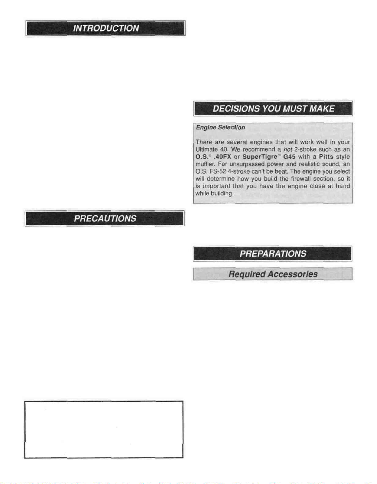
Engine Selection
Preparations
Required Accessories..................................................3
Building Supplies and Tools.........................................4
Optional Supplies and Tools
Types
Common Abbreviations................................................4
Building Notes..............................................................5
Get Ready to
Inch/Metric Ruler..........................................................5
Die-Cut Patterns...................................................... 6&7
Build the Tail Surfaces.....................................................8
Build
Build the Elevator.........................................................8
Build the Fin. .
Build the Rudder..........................................................9
Hinge the Tail Surfaces..............................................10
Finish the Tail Surfaces..............................................10
Fit the Torque Rods
Install Tailwheel Bracket on Rudder...........................11
Build the Bottom Wing...................................................12
Wing Preassembly.....................................................12
Build the Wing.. . . . ...............................................12
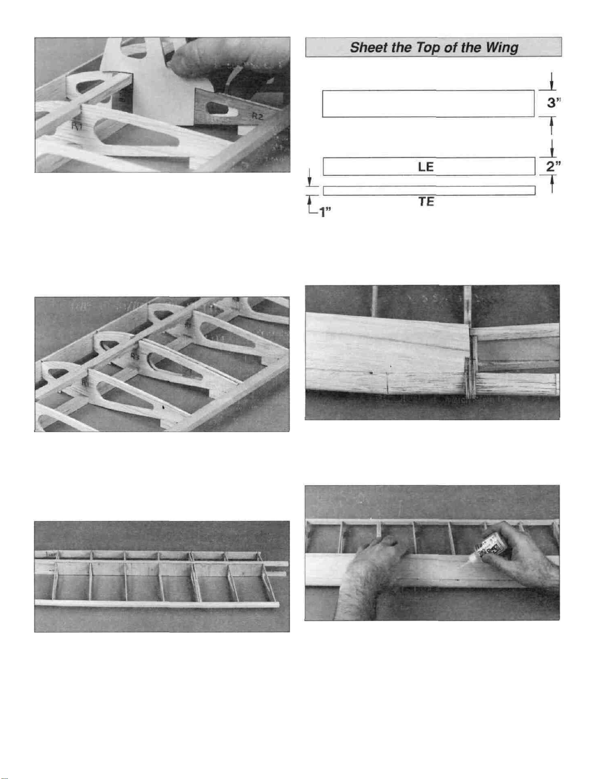
Sheet the Top of the Wing..........................................14
Sheet the Bottom of the Wing....................................15
Complete the Bottom Wing........................................16
Build
Build
the Fuselage
Fuselage Preassembly.. ...........................................18
Assemble the Fuselage Sides ...................................19
Install the Formers
Mount the Wing on the Fuselage...............................22
Install the Stabilizer and Fin .... .................................23
Assemble the Turtledeck............................................24
Build the Top Deck.....................................................25
Build the Top Wing.........................................................27
Wing Preassembly.....................................................27
Build
Sheet the Top of the Wing..........................................30
Install the Aft Root Ribs..............................................30
Finish Sheeting the Top
Sheet the Bottom of the Wing.. .................................31
Complete the Bottom of the Wing ..............................32
Build
Engine
Assemble the Plastic Parts
Assemble the Wheel Pants........................................34
Assemble the Cowl
Balance the Model Laterally..........................................37
Covering.......................................................................37
Prepare the Surface..................................................37
Covering Technique...................................................37
Suggested Covering Sequence................................38
......................................................................3
Make................................................3
.........................................................3
.....................................................................3
........................................4
of
Wood
.......................................................4
Build.......................................................5
the Stabilizer
the Ailerons
the Wing ...
the Ailerons
Installation
.......................................................8
............................................................9
...................................................11
.......................................................17
.........................................................18
.....................................................20
....
..............................................27
of
the Wing
.......................................................33
.........................................................33
...........................................34
...................................................36
..........................31
Painting........................................................................38
Final
Hookups and Checks
Install
the Hinges
Install the Hardware...................................................39
Attach the Canopy .....................................................39
Radio Installation ...........................................................40
Install the Rudder, Elevator and Throttle Servo .........40
Install the Aileron Servo
Check the Wing Incidence.............................................43
Set the Control Throws.................................................43
Balance
Preflight...........................................................................44
AMA Safety Code............................................................46
Flying...............................................................................46
2-View Drawing
Your Ultimate 40 is not a toy, but rather a sophisticated,
working model that functions very much like a full size
airplane Because of its realistic performance, the
Ultimate 40, if not assembled and operated correctly,
could possibly cause injury to yourself or spectators and
damage property.
If this is your first biplane model, we recommend that you
get help from an experienced, knowledgeable modeler with
your first flights. You'll learn faster and avoid risking your
model before you're ready to take the controls for yourself.
For information on flying clubs in your area, you can
contact the national Academy of Model Aeronautics (AMA),
which has more than 2,500 chartered clubs across the
country Contact AMA at the address or toll-free phone
number below:
Your
Model
Charge the Batteries..................................................44
Balance the Propeller.................................................45
Find a Safe Place to
Ground Check the Model
Range Check Your Radio...........................................45
Engine Safety Precautions........................................45
General.....................................................................46
Radio
Control............................................................46
Takeoff.......................................................................47
Flight.........................................................................47
Landing..................................................................... 47
Flight
Log...................................................................47
Or via the internet at: http://www.modelaircraft.org
.......................................................38
.......................................................44
...............................................Back
...........................................38
.............................................42
Fly.............................................45
...........................................45
Cover
Academy of Model Aeronautics
5151 East Memorial Drive
Muncie, IN 47302-9252
Tele (800)435-9262
Fax (765) 741-0057
2
Page 3
The Great Planes Ultimate 40 is a high performance,
propeller-driven sport biplane that closely resembles the
full size Ultimate The Ultimate 40 is very stable and
forgiving, allowing even intermediate skill level pilots to
enjoy it
This is not a beginner's airplane! While the Ultimate 40
is easy to build and flies great, we must discourage you
from selecting this kit as your first R/C airplane It lacks the
self-recovery characteristics of good basic trainers such as
the Great Planes PT" Series On the other hand, if you
have already learned the basics of R/C flying, and you are
able to safely handle a 40-size low wing airplane, the
Ultimate 40 is an excellent choice to try your skills at flying
a biplane.
Remember: Take your time and follow directions to end
up with a well-built model that is straight and true.
Please inspect all parts carefully before starting to build!
If any parts are missing, broken or defective, or if you
have any questions about building or flying this
airplane, please call us at (217) 398-8970. If you are
calling for replacement parts, please reference the part
numbers and the kit identification number (stamped on
the end of the carton) and have them ready when calling.
1 You must assemble the model according to the
instructions Do not alter or modify the model, as doing so
may result in an unsafe or unflyable model In a few cases
the instructions may differ slightly from the photos In those
instances the plans and written instructions should be
considered as correct.
2 Take time to build straight, true and strong
3 Use an R/C radio system that is in first-class condition,
and a correctly sized engine and components (fuel tank,
wheels, etc ) throughout your building process.
4. You must properly install all R/C and other components
so that the model operates properly on the ground and in
the
air.
5 You must test the operation of the model before every
flight to insure that all equipment is operating, and you must
make certain that the model has remained structurally
sound Be sure to check clevises or other connectors often
and replace them if they show signs of wear or fatigue.
NOTE We, as the kit manufacturer, can provide you
with a top quality kit and great instructions, but ultimately
the quality of your finished model depends on how you
build it, therefore, we cannot in any way guarantee
the performance of your completed model, and no
representations are expressed or implied as to the
performance or safety of your completed model.
Items in parentheses (GPMQ4243) are suggested part
numbers recognized by distributors and hobby shops and
are listed for your ordering convenience GPM is the Great
Planes brand, TOP is the Top Flite" brand, and HCA is the
Hobbico brand.
D Four-channel radio with four servos
D Engine - See Engine Selection above
D Propeller (Top Flite Power Point"), Refer to your
engine's instructions for proper size
D Fuel tank 10oz (GPMQ4104)
D Medium fuel tubing (GPMQ4131)
D 2-1/4" Main wheels (GPMQ4222)
D 1"Tailwheel(GPMQ4241)
D Top Flite MonoKote (Approximately 3 rolls)
D Pilot figure (Williams Bros #185)
D 1/4" Latex foam rubber padding (HCAQ1000)
D Switch and charge jack (GPMM1000)
D Top Flite LustreKote" Paint - See Painting (page 37)
D 1/16" Wing seating tape (GPMQ4422)
D 6" Servo extension
D 2-1/2" White spinner (GPMQ4520)
D Fuel fill valve (GPMQ4160)
3
Page 4
These are the building tools that are required. We
recommend Great Planes Pro" CA and Epoxy glue.
D 2 oz. Pro CA (Thin, GPMR6003)
D 2 oz Pro CA+ (Medium, GPMR6009)
D 1 oz Pro CA- (Thick, GPMR6014)
D 6-Minute Pro Epoxy (GPMR6045)
D 30-Minute Pro Epoxy (GPMR6047)
D Hand or electric drill
D Sealing iron (TOPR2100)
D Heat gun (TOPR2000)
D Hobby saw
D Hobby knife, #11 Blades
D Razor plane (Master Airscrew®)
D Pliers (Common and Needle Nose)
D Screwdrivers (Phillips and flat tip)
D T-pins (HCAR5150)
D 60" Retractable Tape Measure (HCAR0478)
D Straightedge with scale
D Masking tape (TOPR8018)
D Sandpaper (coarse, medium, fine grit)
D Easy-Touch" Bar Sander (or similar)
D Plan Protector (GPMR6167)
D Lightweight balsa filler such as Hobbico^ HobbyLite"
(Hobbico HCAR3400)
D 1/4-20 Tap and Drill (GPMR8105)
D IsopropyI rubbing alcohol (70%)
D White body putty (Squadron SQUR1500)
D Ballpoint pen
D 90° Building square (HCAR0480)
D Micro balloons (TOPR1090)
D Canopy glue
D Drill bits 1/16", 5/64", 3/32", 7/64", 1/8", 9/64", 5/32",
3/16", 13/64", 1/4", 5/16", 3/8"
D Builders triangle set (HCAR0480)
Custom sanding blocks can be made from balsa or hardwood
blocks and dowels for sanding difficult to reach spots
D CA Applicator Tips (HCAR3780)
D Epoxy brushes (GPMR8060)
D Epoxy mixing sticks (GPMR8055)
D CA Debonder (GPMR6039)
D Hot Sock "(TOPR2175)
D Single-edge razor blades (HCAR0312)
D Curved tip canopy scissors for trimming plastic parts
(HCAR0667)
D 4 oz Pro Wood Glue (GPMR6161)
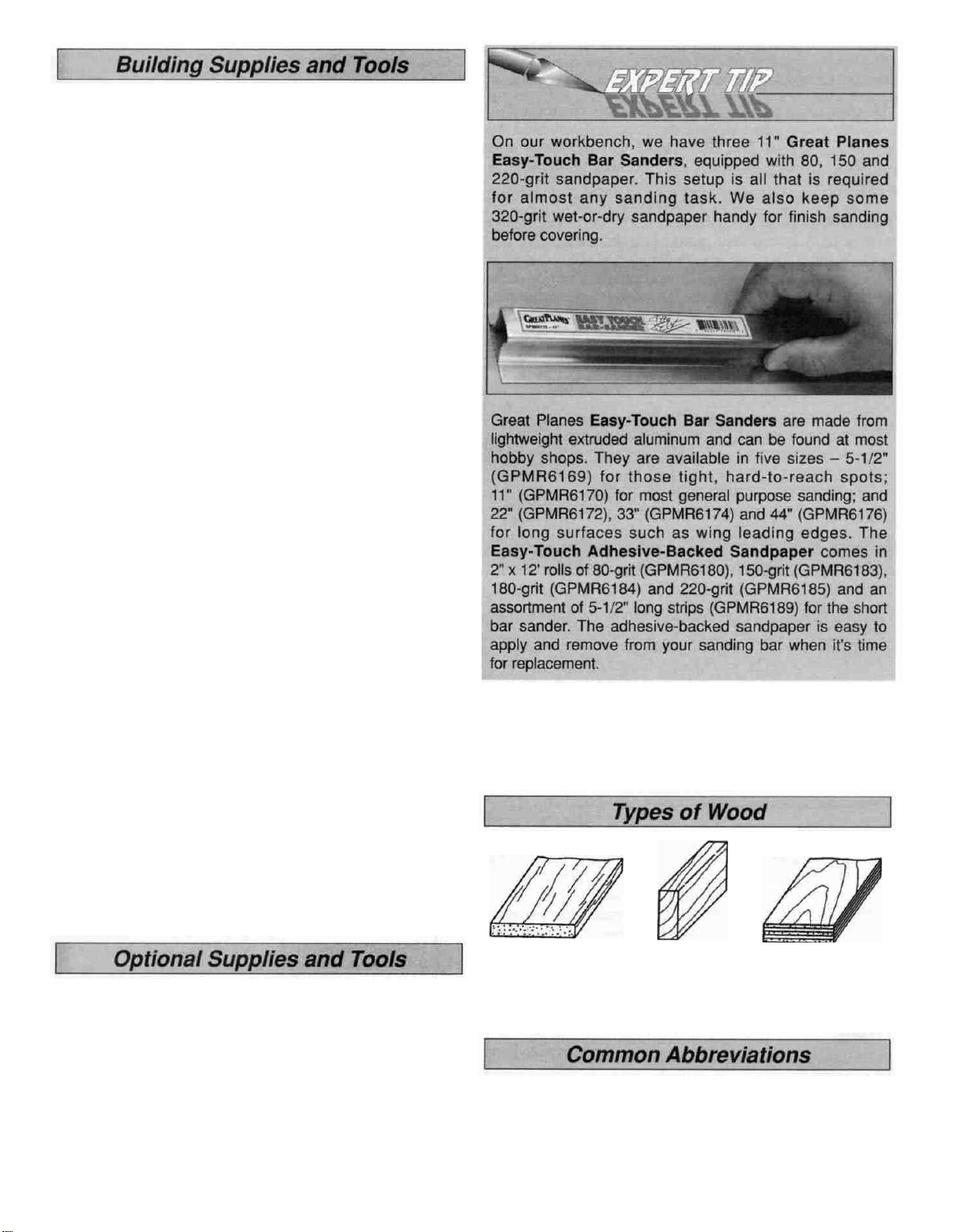
Balsa Basswood Plywood
Elev = Elevator
LE = Leading Edge (front)
Ply = Plywood
TE = Trailing Edge (rear)
4
Fuse = Fuselage
LG = Landing Gear
Stab = Stabilizer
" = Inches
Page 5
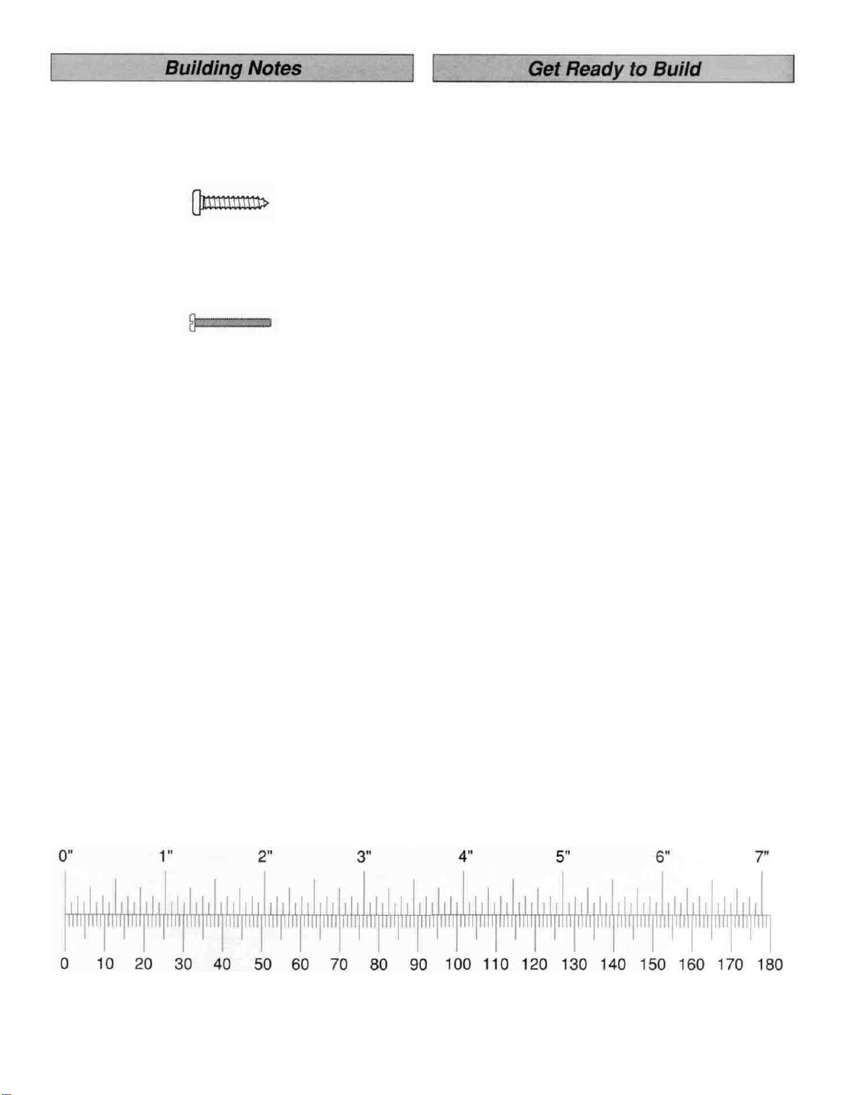
There are two types of screws used in this kit.
Sheet metal screws are designated by a number and a
length. For example #6 x 3/4"
Machine screws are designated by a number, threads per
inch and a length. For example 4-40 x 3/4"
When you see the term "test fit" in the instructions, it
means you should first position the part on the assembly
without using any glue and then slightly modify or sand
the part as necessary for the best fit
Whenever the instructions tell you to glue pieces together,
CA or epoxy may be used When a specific type of glue is
required, the instructions will state the type of glue that is
highly recommended. When 30-minute epoxy is specified,
it is highly recommended that you use only 30-minute (or
slower) epoxy because you will need either the working
time or the additional strength.
D 1. Unroll the plan sheets Reroll the plan sheets inside
out to make them lie flat Place wax paper or Great Planes
Plan Protector over the plan to prevent glue from sticking to
the plan.
D 2 Remove all parts from the box As you do, determine
the name of each part by comparing it with the plan and
the parts list included with this kit Using a felt-tip or
ballpoint pen, lightly write the part name or size on each
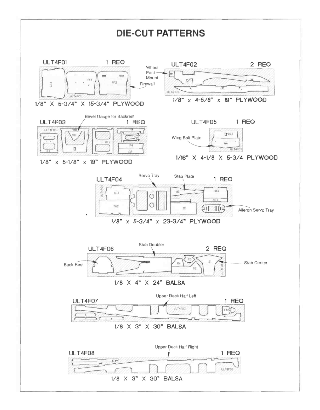
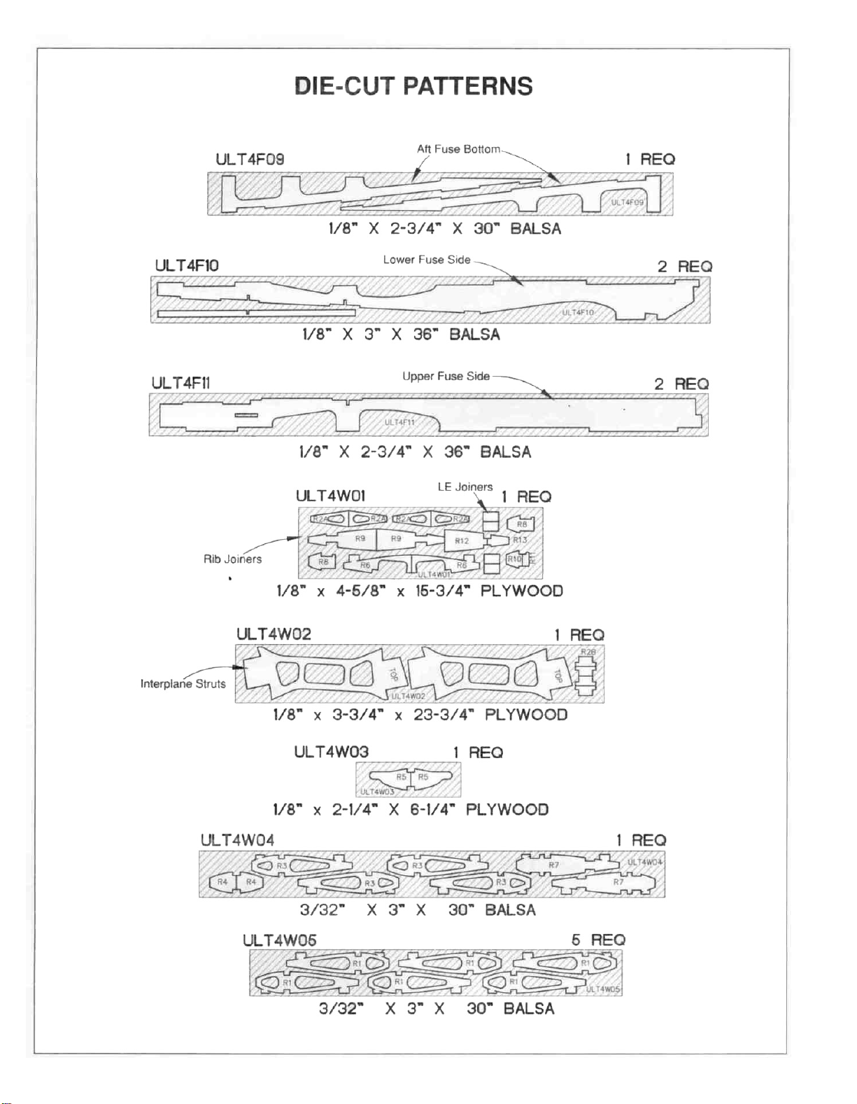
piece to avoid confusion later Use the die-cut patterns
shown on pages 6 and 7 to identify the die-cut parts and
mark them before removing them from the sheet Save all
scraps If any of the die-cut parts are difficult to remove, do
not force them' Instead, cut around the parts Use your
Easy-Touch Bar Sander or sanding block to lightly sand
the edges to remove any die-cutting irregularities.
D 3. As you identify and mark the parts, separate them
into groups, such as fuse (fuselage), wing, fin, stab
(stabilizer) and hardware Resealable food storage bags
are handy to store parts in as you sort, identify and
separate them into subassemblies.
Several times during construction we refer to the "top" or
"bottom' of the model or a part of the model For example,
during wing construction we tell you to "glue the top main
spar" or "trim the bottom of the former" It is understood that
the "top" or "bottom" of the model is as it would be when the
airplane is right side up and will be referred to as the "top"
even if the model is being worked on upside-down (i e the
"top" main spar is always the 'top" main spar, even when
the wing is being built upside-down).
Inch Scale
Metric Scale
5
Page 6
6
Page 7
7
Page 8
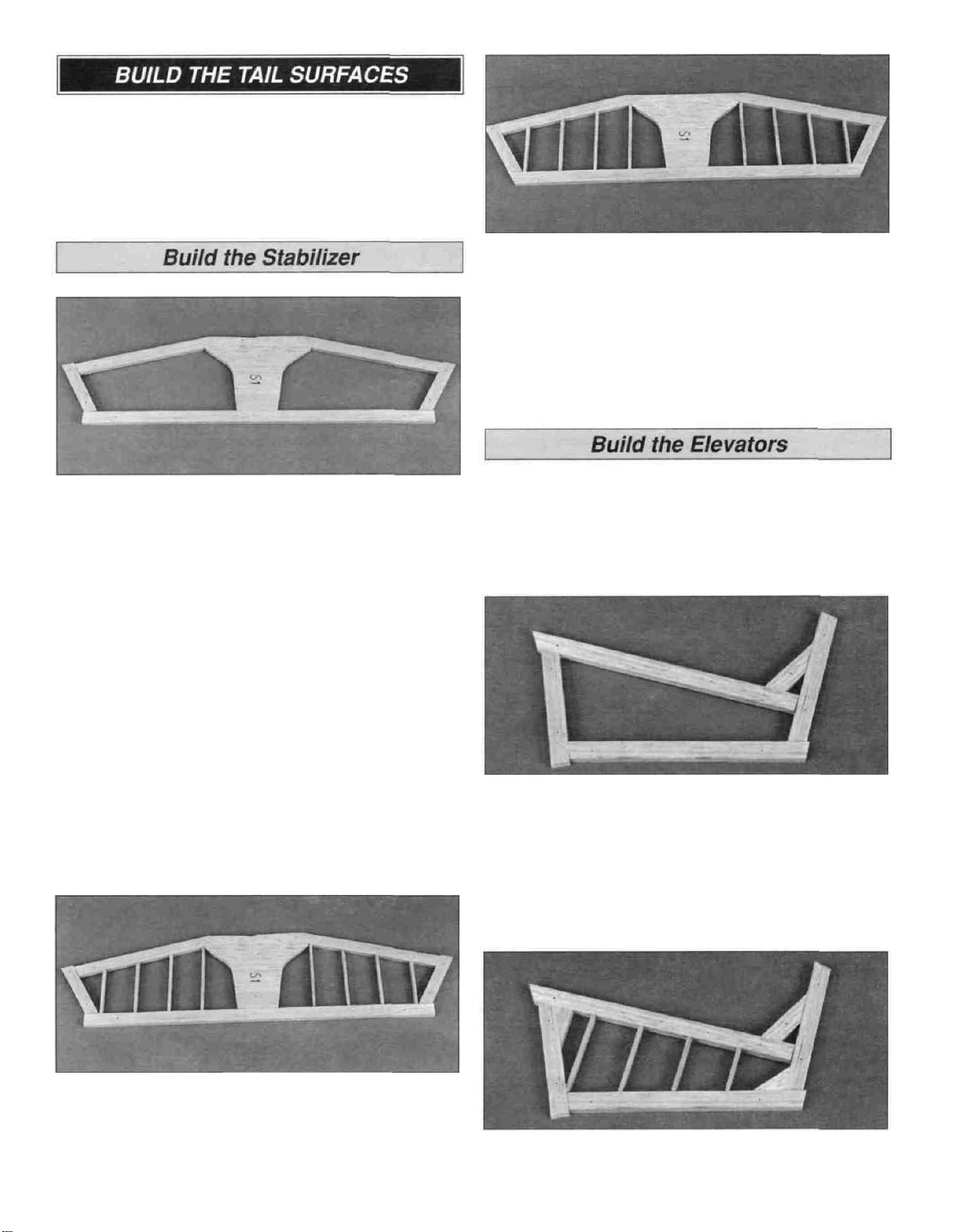
Glue together the pairs of die-cut 1/8" balsa stabilizer
center S-1, fin bottom S-2, rudder bottom R-3 and
rudder tip R-4 to make 1/4" thick parts.
D 3 Remove the stab from your building board Inspect all
the glue joints and add CA to any joints that don't look
strong Sand the LE and TE flush Sand the entire top and
bottom surfaces of the stab until they are flat and even Be
careful that you don't sand any area of the stab too thin.
D 1 Pin the die-cut 1/4" balsa stabilizer center S-1 over
the stabilizer plan Cut the stab outer frame from a
1/4" x 1/2" x 36" balsa stick, allowing approximately 1/16"
extra at the joints The joints will be sanded flush after the
stab is removed from the building board Glue the outer
frame and stab center together and pin it in position over
the plan Use the plans or a straightedge as a guide to
make sure the stab TE is straight as you glue it in position.
Note: Refrain from using excessive accelerator Hours
after it's sprayed on residual accelerator can prematurely
and unexpectedly cure the CA you use later, on nearby
glue joints Unless you must handle or remove the part
from your building board right away, we recommend
using no accelerator at all.
D D 1 Cut a 1/4" x 1/2" x 36" balsa stick to make the
elevator LE and TE Pin the LE and TE in position over the
plan Allow the LE to extend 1/16" past the root and the TE
to extend 1/16" past the tip.
D D 2. Cut the root and tip frame from the remaining
1/4" x 1/2" x 36" balsa stick Glue and pin the elevator in
position over the plan.
D D 3 Cut gussets from a 1/4" x 1/2" x 36" balsa stick
and glue them in place
D 2 Make the 1/8" stab ribs from a 1/8" x 1/4" x 36" balsa
stick. Glue the ribs in position.
Hint: Use a sharp, single-edge razor blade to cut the
stab ribs.
D D 4 Make the 1/8" elevator ribs from a 1/8" x 1/4" x
36" balsa stick and glue them in place
8
Page 9
D D 5. Remove the elevator from your building board.
Inspect all the glue joints and add CA to any joints that
don't look strong. Sand the LE,TE, root and tip flush. Sand
the entire top and bottom surface of the elevator flat and
even. Be careful that you don't sand any area too thin.
D 6. Go back to step 1 and build the second elevator
following the same procedure.
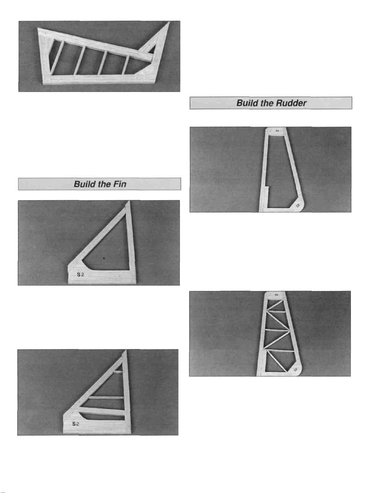
D 3. Remove the fin from your building board. Inspect all
the glue joints and add CA to any joints that don't look
strong. Sand the joints flush and the entire top and bottom
surfaces of the fin flat and even. Be careful that you don't
sand any area too thin.
D 1. Pin the die-cut 1/4" balsa fin bottom S-2 over the fin
plan. Cut the fin outer frame from a 1/4" x 1/2" x 36" balsa
stick, allowing approximately 1/16" extra at the joints. Glue
the outer frame and fin bottom together and pin it in
position over the plan. Use the plans or a straightedge as a
guide to make sure the fin TE is straight as you glue it in
position.
D 1. Pin the die-cut 1/4" balsa rudder bottom R-3 and
rudder tip R-4 over the rudder plan. Cut the rudder outer
frame from a 1/4" x 1/2" x 36" balsa stick, allowing
approximately 1/16" extra at the joints. Glue the outer
frame, rudder bottom and rudder tip together and pin it in
position over the plan. Use the plans or a straightedge as a
guide to make sure the rudder LE is straight as you glue
it in position.
D 2. Cut the rudder ribs and diagonal braces from the
remaining 1/8" x 1/4" x 36" balsa stick. Glue the ribs and
braces in position.
D 2. Cut the top two fin ribs from the remaining
1/8" x 1/4" x 36" balsa stick. Cut the bottom rib from a
1/4" x 1/2" x 36" balsa stick. Glue the fin ribs to the fin LE
and
TE.
D 3. Cut the remaining 1/4" x 1/2" x 36" balsa stick to
make the LE gusset. Glue the gusset in position.
D 4. Remove the rudder from your building board. Inspect
all the glue joints and add CA to any joints that don't look
strong. Sand the joints flush and the entire top and bottom
surface of the rudder flat and even. Be careful that you
don't sand any area too thin.
9
Page 10
D 1. Place the stab and elevators over their locations on
the plan and lightly mark the hinge locations on the TE of
the stab and LE of the elevators.
D 4. Cut the hinges for the elevators and rudder from the
supplied 2" x 9" hinge material. Use the hinge drawing
on the fuse plan as a guide. Trim off the corners and
temporarily join the elevators to the stabs with the hinges,
adjusting any hinge slots if necessary. Do not glue in the
hinges until you are instructed to do so.
D 2. Mark the centerline of the hinges on the stab's TE
and elevator's LE using the following centerline method.
HOW TO MARK A CENTERLINE
It's important that the hinges are centered and parallel to
the part you are hinging. The best way to start is by
accurately marking the hinge centerline.
A. Lay the stab and a ballpoint pen on a flat surface.
Mark a "test line" on the trailing edge of the stab.
D 5. Return to step 1 and use the same procedure to
hinge the rudder and fin.
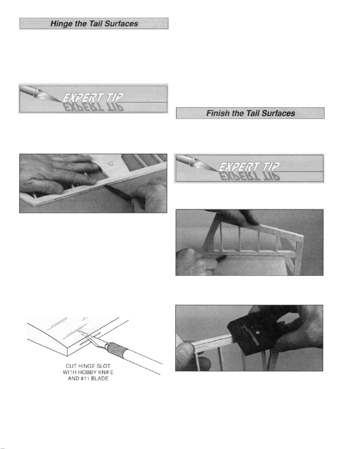
D 1. Refer to the Expert Tip that follows and shape the LE
of the elevators and rudder to a "V" shape as shown on
the plans.
HOW TO BEVEL THE LEADING EDGE
B. Flip the stab over and mark another line in the same
location as the first. If you see only one line, then it is
on center. Proceed and mark the centerline at each
hinge location. If you see two lines, use playing cards
or business cards to adjust the height of the pen until
you can mark the centerline.
C. Use the same technique to mark the centerline along
the entire length of both elevators.
D 3. Cut the hinge slots in the elevator and stab using a
#11 blade. Begin by carefully cutting a very shallow slit at
the hinge location to accurately establish the hinge slot.
Make three or four more cuts, going a little deeper each
time. As you cut, slide the knife from side to side until the
slot has reached the proper depth and width for the hinge.
A. Place the leading edge of one of the elevators on your
work surface and use your ballpoint pen to mark a
"bevel to" line on both sides about 1/8" high.
B. Using the bevel to lines and the centerline as a guide,
make the "V" on the leading edge of the elevators with
a razor plane or your bar sander.
D 2. Use the same procedure to bevel the leading edge of
the rudder.
10
Page 11
D 3 Draw a centerline on the LE of the stab and fin and on
the TE and tip of the elevators and rudder Sand a radius
on the edges as shown on the plan using the centerline as
a guide to keep the radius symmetrical Do not round the
TE of the stab or fin.
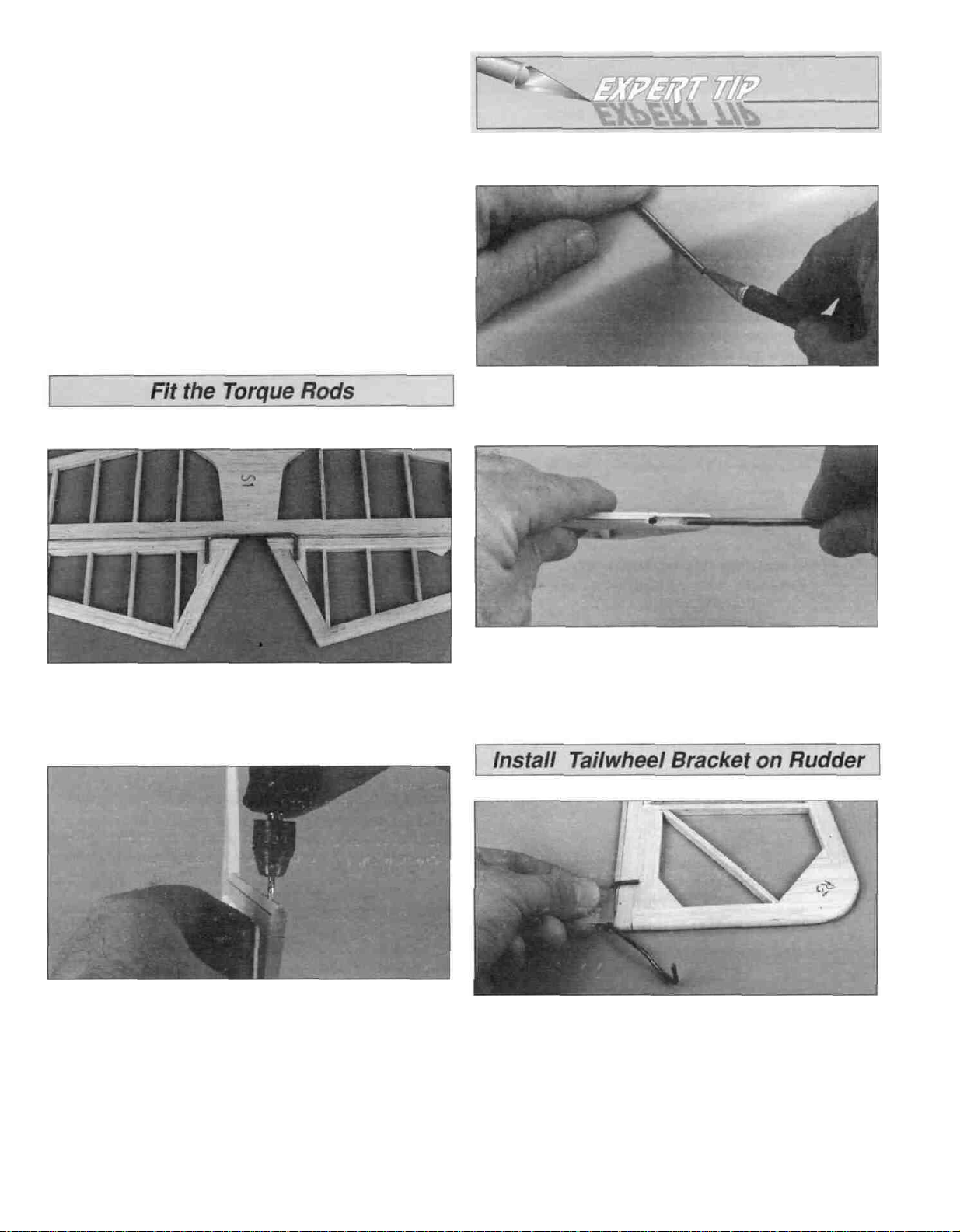
HOW TO CUT A GROOVE FOR A TORQUE ROD
A. Use a hobby knife to sharpen the inside of a piece of
1/8" brass tube Roll the tube as you carve the end.
D 1 Position the stab and elevators over the fuselage top
view Mark the location of the elevator joiner on the elevators.
D 2 Drill 3/32" pilot hole into the elevator LE, on the
centerline, at the torque rod marks As you drill the holes
keep the drill aligned with the top and bottom surfaces of
the elevator Enlarge the holes with a 1/8" drill bit.
B. Use the sharpened tube to carefully gouge the leading
edge You II have to make several passes to make the
recess deep enough for the torque rod.
D 1 Position the rudder over the plan and align the
tailwheel bracket over the rudder Mark the tailwheel
bracket "arm" location on the LE of the rudder. Drill a 7/64"
hole, 3/4" deep at the mark.
D 3 Cut a 1/8" groove in the leading edge of both
elevators to recess the joiner wire (see expert tip that
follows) Do not glue the joiner wire in position at this time.
D 2 Cut a groove from the tailwheel bracket hole to the
bottom of the rudder that will allow the nylon tailwheel
bearing to fit flush with the LE of the rudder Do not glue
the tailwheel bracket in at this time.
11
Page 12
The Ultimate 40 bottom wing is built as one piece.
D 1. Pin the die-cut 3/32" balsa ribs R-1 in position over
the main spar.
Note: The jig tabs should be contacting the plan. Use
small T-pins to pin the aft jig tabs to the building board
over their location on the plan.
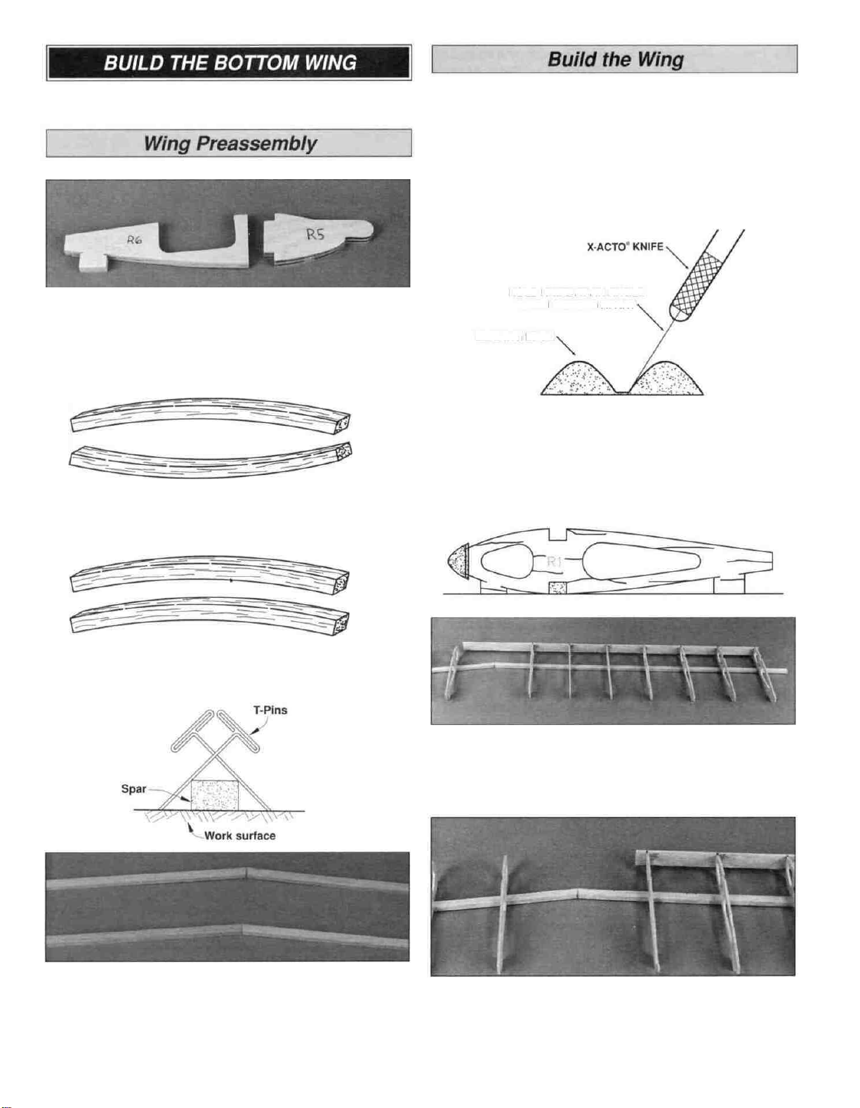
D 1. Use 30-minute epoxy to glue together the die-cut 1/8"
plywood ribs R-5 and R-6.
TWO WARPED SPARS INSTALLED
THIS WAY WILL RESULT IN A
STRAIGHT WING
TWO WARPED SPARS INSTALLED
THIS WAY WILL RESULT IN A
WARPED WING
D 2. Match sets of 1/4" x 3/8" x 24" balsa wing spars so
any warps will counteract each other.
HOLD KNIFE AT AN ANGLE
WHEN CUTTING APART
LEADING EDGE
D 2. The shaped and notched balsa wing LE and TE are
fastened together by thin strips of balsa. Separate them by
cutting with a hobby knife, as shown in the sketch above.
D 3. Trim the end of two main spars to the angle shown
on the plan. Use 6-minute epoxy to glue the ends of
the main spars together. Before the epoxy cures, use the
cross-pinning technique (see sketch above) to pin the main
spars against the building board.
D D 3. Center the LE vertically on the front of the ribs with
each rib inserted in its respective notch. Use a straightedge
to check that the LE is straight before gluing it in position.
D D 4. Cut the LE at the root as shown on the plan. Save
the piece you cut off for the wing center section.
D 5. Repeat the process to install the other LE.
12
Page 13
D 6. Position the TE on the aft end of the ribs, flush with
the top and bottom edge of the ribs. Use a straightedge to
check that the TE is straight before gluing it in position.
Trim the root end to match the plan.
D 7. Fit the second TE, trimming the root end to butt
against the first TE. Use a straightedge to check that the
TE is straight before gluing it in position.
D 8. Glue ribs R-1 to the bottom main spar, perpendicular
to the building board.
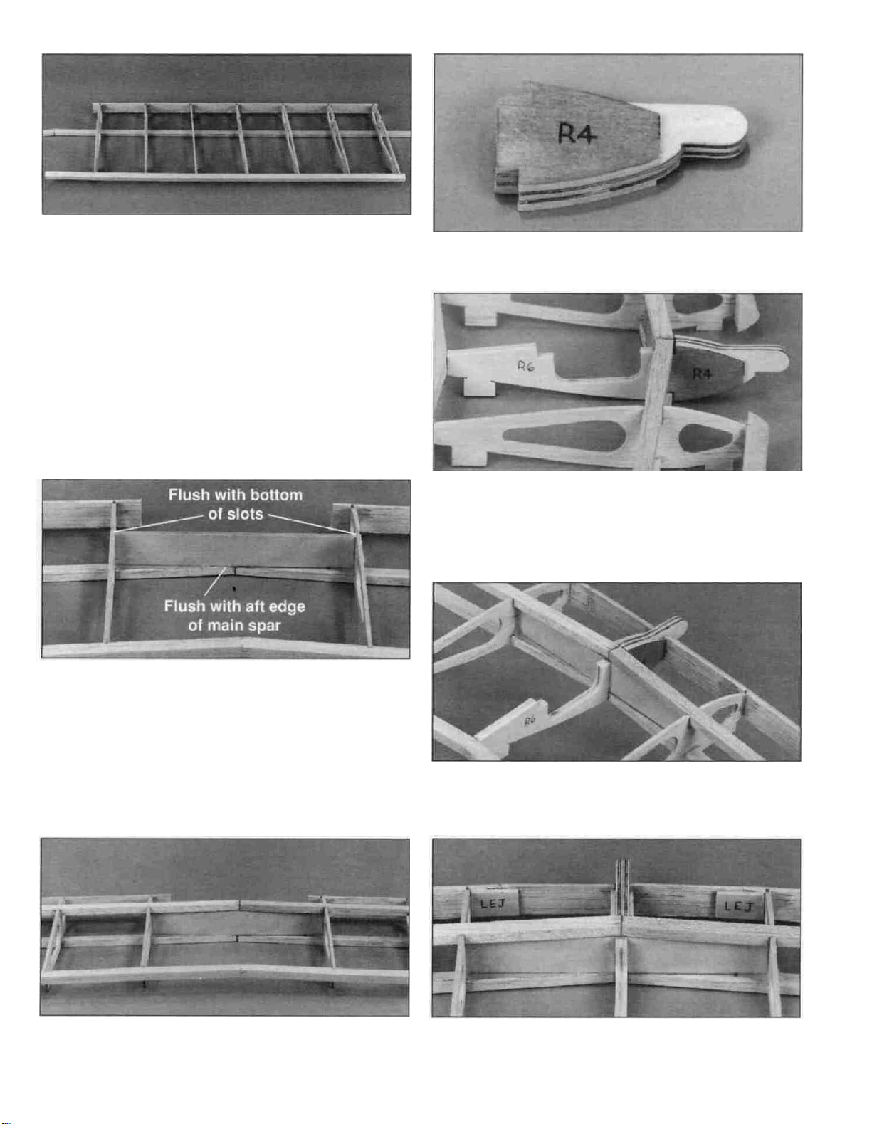
D 11. Glue the die-cut 3/32" balsa ribs R-4 flush with both
sides of R-5.
D 12. Use 6-minute epoxy to glue rib R-6 to the joiner
and the TE. Make sure that the rib is seated on and
perpendicular to the building board. Glue rib R-5 to the front
of the joiner and spars, perpendicular to the building board
and parallel with the R-1 root ribs.
D 9. Use 30-minute epoxy to glue the 1/8" plywood joiner
between the R-1 root ribs, perpendicular to the building
board. The center of the joiner should be flush to the aft
edge of the main spar and the joiner ends should be flush
with the forward edge of the main spar. Make sure the top
of the joiner is flush with the bottom of the slots for the top
main spar.
D 10. Use 30-minute epoxy to glue the top spar to the
joiner and thin CA to glue the joiner to the ribs. Hold the
spar in place with a weight until the epoxy cures.
D 13. Trim the leftover LE to fit between ribs R-1 and R-5,
centered on the front of ribs R-4. When satisfied with the fit,
glue them in place.
U 14. Use 6-minute epoxy to glue the die-cut 1/8" plywood
leading edge joiner (LEJ), centered vertically, across the
joint between the center LE and the outer LE.
13
Page 14
D 15 Test fit the die cut 1/8" plywood ribs R-2A and R-2B
in position as shown on the plans Check the fit of the wing
strut between R-2A and the wing spars The strut should fit
snug but be easy to insert and remove When satisfied
with the fit, remove the strut and glue ribs R-2A and R-2B
to
R-1.
D 16 Insert the die-cut 3/32" balsa rib R-3 between the
spars and carefully rotate it into position Glue it to ribs
R-2A, R-2B, the wing spars and the LE and TE.
D 1. Cut the 2" LE and 1" TE sheeting from eight
1/16" x 3" x 24" balsa sheets The LE and TE sheets will be
used on both wings.
D 2 Test fit the LE wing sheet to one wing panel Sand a
slight bevel on the front of the sheet The aft edge of the
sheet should cover the forward half of the main spar The
root end should cover one R-4 and R-5 rib.
D 17 From a 1/16" x 3" x 24" balsa sheet cut and glue
shear webs, perpendicular to the aft edge of the main spars
The shear webs must be glued securely to the main spars.
D 18 Sand the top of the wing so that the spars, shear
webs and TE are flush with the top of the ribs.
D 3 Remove any pins that are holding the wing to the
building board in front of the main spar You may need to
place weights on the wing to keep the main spars flat
against the building board Position the front of the LE
sheet against the LE and glue it in position with thin CA.
D 4 Carefully lift the sheet away from the ribs and apply a
bead of medium or thick CA to the top of the ribs Working
quickly, pull the sheet back toward the main spar as you
press it down against the ribs and the main spar.
14
Page 15
D 5. Use thin CA to glue the LE sheet to the main spar.
D 6. Fit and glue the second LE sheet to the other wing
panel, following the same procedure.
D 7. Glue the 1/16" TE sheet, cut in step 1, to the TE and
the top of the ribs
D 9. From 1/16" x 3/16" x 30" balsa stick, cut and glue cap
strips to the top of the R-1 ribs. The edge of the cap strip
on the R-1 tip rib should be flush with the side of the rib.
Use two cap strips, edge-glued at the center of rib R-2A on
the double rib, for the strut. Trim the cap strip over the slot
for the strut.
Hint: A single-edge razor blade works well for this type
of cutting.
D 10. Remove the wing from your building board. Cut and
sand the LE, TE, main spars and top sheeting flush with the
side of tip rib R-1.
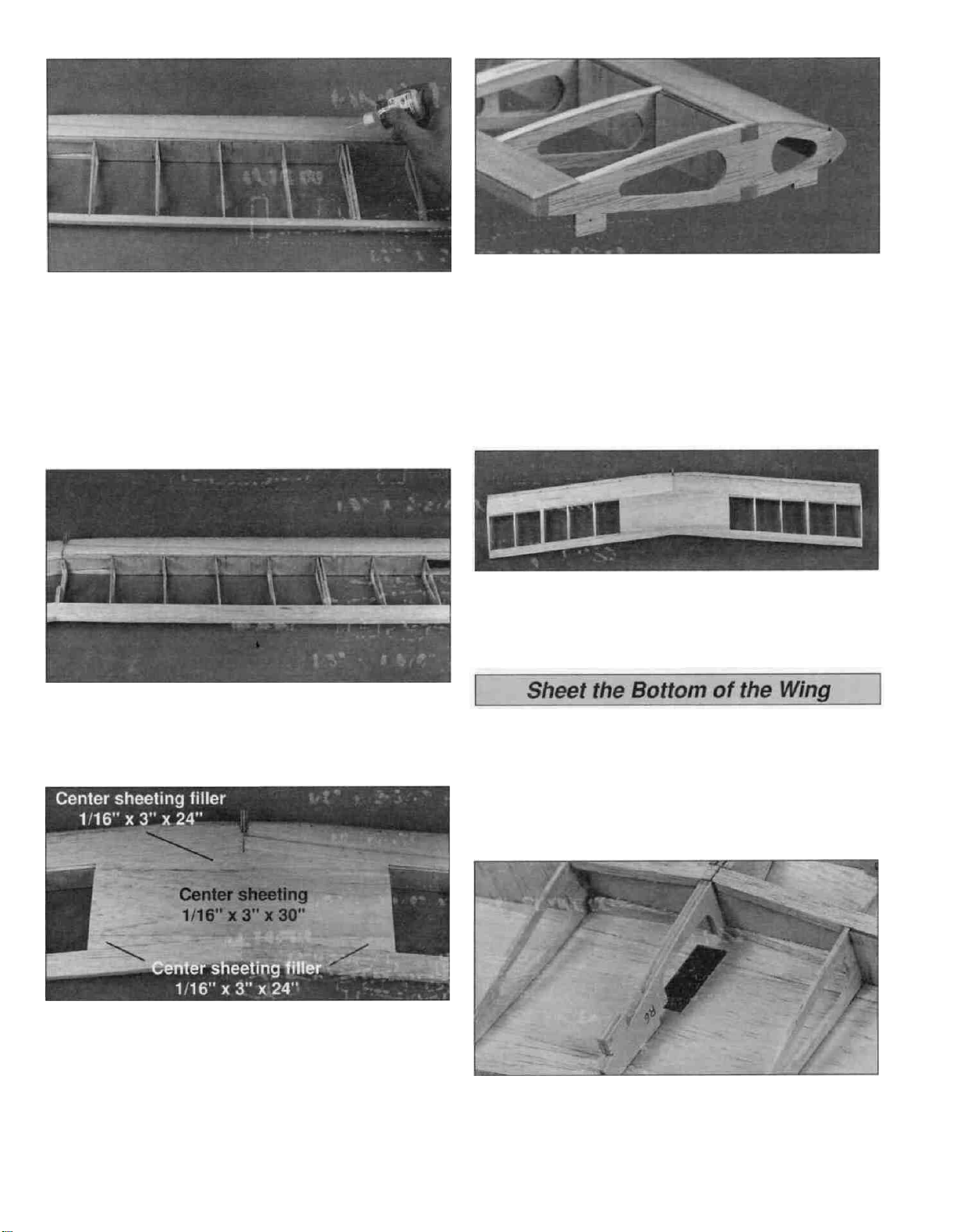
The bottom of the wing is sheeted following the same
procedure as the top of the wing.
D 8. Use a 1/16" x 3" x 30" balsa sheet to make the center
sheeting between the LE sheet and the TE sheet. Save
the remaining sheeting for the bottom center sheeting. The
center sheeting filler is made from a 1/16" x 3" x 24"
balsa sheet.
Note: See the plans for clarity. Before you glue the center
sheeting in position, remove any T-pins from under
the sheeting.
D 1. Use a hobby knife and sanding bar to remove the jig
tabs on the bottom of the ribs. Sand the TE, main spars,
shear webs and the top of the ribs to blend them together.
D 2. Cut out the aileron servo opening in the top center
sheeting using the aileron servo cutout in rib R-6 as a
guide. Make the opening slightly smaller than the servo
cutout in the rib. The opening will be enlarged when the
servo tray is installed.
15
Page 16

D 3. Position the wing on your building board with the
bottom side up. Place weights on the wing to keep the main
spars in contact with the building board. Glue the bottom
LE sheeting in position following the same procedure used
for the top LE sheeting. Remember, you previously cut the
LE sheeting when you sheeted the top of the wing.
D 4. Glue the 1/16" TE sheet, cut in step 1 of "sheet the
top of the wing", to the TE and the bottom of the ribs. Use a
leftover piece of balsa sheeting to fill the gap at the center
of
the
LE.
D 5. Use the 1/16" x 3" x 30" and 1/16" x 3" x 24" balsa
sheeting, leftover from the top center sheeting, to make
the bottom center sheeting between the LE sheet and the
TE sheet.
D 6. Test fit the struts in the slots in the top of the wing,
making sure they seat against the top wing sheeting. From
1/16" x 3/16" x 30" balsa stick, cut and glue cap strips to
the top of ribs R-1. The edge of the cap strip on the R-1 tip
rib should be flush with the side of the rib. Use two cap
strips, edge-glued at the center of rib R-2A on the double
rib, for the strut.
D 7. Trim and sand the LE and TE sheeting flush with the
side of tip rib R-1.
D 3. Mark the location of the aileron torque rod exits. Cut a
notch in the top LE of both pieces as shown.
Note; Be sure you make a right and left piece.
D 4. Roughen both torque rod tubes with coarse
sandpaper and apply a dab of petroleum jelly to the
exposed wire. Use 30-minute epoxy to glue the torque rod
tubes in the slot at the front of the center TE pieces. Before
the epoxy cures, glue the center TE pieces to the TE of the
wing. Wipe off any excess epoxy with a paper towel
dampened with isopropyi rubbing alcohol. Hold the center
TE pieces in place with masking tape until the epoxy cures.
D 8. Make the wing tips from a 1/8" x 3" x 18" balsa sheet.
Hold the sheet against tip rib R-1 and draw an outline of the
rib. Cut and glue the wing tips to tip ribs R-1.
D 1. Sand the TE sheet flush with the aft edge of the TE.
D 2. Position the tapered and grooved 1-1/4" x 4-1/2"
balsa wing center TE pieces over the plan. Trim the root
ends to match the angle shown on the plan. Test fit the
center TE on the TE of the wing.
D 5. Extend the torque rod exit slots into the TE of
the wing.
D 6. Sand the center TE flush with the top and bottom
TE sheeting.
D 7. Draw a centerline on the die-cut 1/16" birch plywood
wing bolt plate. Sand a bevel on the front and sides of
16
Page 17

the wing plate. Leave the aft edge of the wing bolt plate
square Use 30-mmute epoxy to glue the wing bolt plate to
the bottom of the wing, centered on the center TE The aft
corners of the wing bolt plate are flush with the aft end of
the center TE. Use clamps or weights to hold the wing bolt
plate tight against the wing.
D 8. Trim the opening for the aileron servo tray until you
can see the aileron servo cutout in ribs R-6 Center the
die-cut 1/8" plywood aileron servo tray over the cutout
(save the tray doublers die-cut inside the servo tray) Mark
the outside perimeter of the tray and cut the wing sheeting
from inside these lines.
D D 1 Trim one end of the 1-1/4" x 24" balsa aileron to
the same angle as the center TE.
D D 2. With a gap of 1/16" between the aileron and the
center TE, cut the end of the aileron approximately 1/16"
past the wing tip This will allow you to sand the aileron
flush with the wing tip.
D 9. Glue the die-cut 1/8" plywood aileron servo
tray supports to the ends of the aileron servo tray,
perpendicular to the tray Glue the tray doublers to the
bottom of the aileron servo tray.
D 10. Glue the servo tray to ribs R-6
D D 3 Place the left aileron on the trailing edge of the
wing and mark the location of the torque rod.
D D 4. Draw a centerline on the LE of the aileron.
D D 5. Drill a 1/8" hole on the centerline for the aileron
torque rod Use a sharpened 1/8" brass tube to cut a
groove in the LE for the aileron torque rod.
D D 6. Use the leftover hinge material, cut four aileron hinges.
D D 7. Mark the location for the hinges on the aileron and
wing. Cut the hinge slots and without using glue, test fit
the aileron on the wing.
17
Page 18

D D 8. Remove the aileron from the wing. Mark the "bevel
to" lines and sand the LE of the aileron to a "V" as shown
on the plan.
D 9. Perform steps 1 through 7 to fit the second aileron
onto the wing.
Great looking wing! Guess what? You still have to build the
top wing.
We will build the fuselage next. It will be needed when you
assemble the top wing.
Completely read this section on Fuselage Preassembly and
test fit all the parts. These parts require the strength and
working time of 30-minute epoxy glue. This extra working
time will allow you to assemble most of the parts at once.
D 2. Glue the die-cut 1/16" birch plywood F-8A doubler to
the front of the die-cut 1/8" plywood former F-8B. Make
sure the slots in F-8A and F-8B are aligned.
D 3. After the epoxy has cured, drill 5/32" holes at the four
engine mount punch marks. Drill a 3/16" hole for the throttle
pushrod at the appropriate location. Drill two 1/4" fuel line
holes in the center of the engine mount holes.
D 1. Glue the three die-cut 1/8" ply firewall formers FF-1,
FF-2 and FF-3 together. Former FF-2 must be sandwiched
between FF-1 and FF-3. Make sure that the embossed
label on each former is facing forward and the top and side
edges are aligned. The bottom edges will be offset. Wipe
off any excess epoxy before it cures.
Note: If the formers are warped, clamping them together
will not remove the warp. It is best to clamp them to a flat
table or board.
D 4. Press four 6-32 blind nuts into the holes from the
back of the firewall. Tap the blind nuts with a hammer to
fully seat them and apply a few drops of thin CA around
each blind nut to secure them in position.
D 5. Drill 3/16" holes at the punch marks in the die-cut 1/8"
plywood fuselage formers F-10 and F-11.
18
Page 19

D 6. Cut 1/4" from the front of one die-cut 1/8" balsa lower
fuse side, one upper fuse side, one die-cut 1/8" plywood
lower fuse doubler and one upper fuse doubler. Mark
each of these parts right side.
D 7. Drill 1/8" holes at the punch marks on the upper fuse
doublers. Drill 5/16" holes at the punch marks on the upper
fuse sides.
D 1. Build two fuse sides by gluing together the balsa
lower and upper fuse sides. Make sure to glue the two
right side pieces together.
D 2. Sand the fuse sides smooth.
D 3. Caution: Make sure to glue the right side doublers to
the right side fuse. Position the fuse sides next to each other
as shown. Glue the die-cut 1/8" lower fuse doublers to the
fuse sides, aligning the edges of the wing saddle and the
forward edges. Glue the die-cut 1/8" top fuse doublers to
the fuse sides, aligning the top and front edges.
D 8. Glue the die-cut 1/8" balsa aft fuse bottom together.
D 9. Glue the die-cut 1/8" balsa fuse top deck together.
D 4. Glue the die-cut 1/8" balsa aft fuse doubler to the aft
fuse sides. Align the notch and the pushrod exit slot.
19
Page 20

Important: Install all formers with the embossed lettering
facing the nose of the fuse. Do not glue the fuse together
until instructed to.
D 1. Insert die-cut 1/8" plywood formers F-10, F-11 and
F-12 into their appropriate slots in the fuse sides. Make
sure the modified right fuse side is on the right side. Use
rubber bands placed around the fuselage sides to hold the
formers in place.
D 4. Install the die-cut 1/8" plywood formers F-9, F-8A/B
and the firewall as you pull the fuse sides together. You
may need to use clamps, placed along the bottom of the
fuse, along with rubber bands to hold the sides together.
D 5. Align the fuse over the bottom view of the fuse plan
with the firewall hanging over the edge of the building board.
With the formers perpendicular to your building board, use
thin CA to glue formers F-12 thru F-8A/B to the fuse sides,
top deck and aft fuse bottom. The fuse sides should be
perpendicular to the building board from the tail to former
F-10. At F-10 the bottom of the fuse starts to taper in. The
bottom of former F-8A/B is glued flush with the front of the
wing saddle. Do not glue the firewall at this time.
D 6. After gluing the joints with thin CA, go back and
reinforce all joints with medium CA. After the CA cures,
remove the rubber bands and clamps.
D 2. Install the aft fuse bottom.
D 3. Install the fuse top deck.
Note: The front of the top deck is angled to build right
thrust in the firewall. Use rubber bands to temporarily hold
the tail section together.
D 7. With the fuse still positioned over the fuse plan bottom
view, use 30-minute epoxy to glue the firewall to the
fuse sides.
D 8. Use 6-minute epoxy to glue 3/8" balsa triangle sticks
to the joints between the fuse sides, the top deck and
the firewall.
20
Page 21

D 9. Fit the die-cut 1/8" plywood landing gear braces F-4,
F-7 and the 1/4" plywood landing gear plate in the fuse
sides. Use 6-minute epoxy to glue the braces and plate
in position.
U 10. The two outer holes in the aluminum landing gear
may need to be enlarged to 5/32".
D 13. Remove the landing gear. Use 6-minute epoxy to
glue the die-cut 1/8" plywood landing gear back plate
(FB-3) to the fuse sides, F-7 and F-8A/B.
D 14. Trim the angled notch in the bottom of the firewall so
that the die-cut 1/8" plywood forward bottom plate (FB-1)
fits flush with the fuse sides. Use 6-minute epoxy to glue
the plate in place and to make a fillet between the firewall
and the plate on the inside of the fuse.
D 11. Center the landing gear on the shaped 1/4" plywood
landing gear plate and mark the three mounting holes.
Remove the landing gear and drill 5/32" holes through the
plate at the marks.
D 12. Place the landing gear on the landing gear plate.
Insert 6-32 x 1/2" cap head screws with #6 washers
through the landing gear and landing gear plate. Thread a
6-32 blind nut on the cap head screw from the back side of
the landing gear plate. Screw the cap head screw into the
blind nut pulling it into the landing gear plate. Apply a few
drops of thin CA around each blind nut flange to secure
them in position.
D 15. Sand the bottom edge of the forward bottom plate
flush with the lower fuse doublers and former F-4. Use
6-minute epoxy to glue the die-cut 1/8" plywood landing
gear front plate (FB-2) to F-4, the lower fuse doublers and
the forward bottom plate. The back edge of the front plate
should be flush with F-4.
D 16. Sand the landing gear front plate flush with the
forward bottom plate. Sand the fuse sides and the forward
bottom plate flush with the firewall.
D 17. Now is the best time to fuelproof the fuel tank
compartment. Use fuelproof model paint, 30-minute
epoxy thinned with alcohol or finishing resin to coat the
compartment. Do not get paint or epoxy on the threads of
the blind nuts. Also fuelproof one side and the edges of the
fuel tank floor.
21
Page 22

D 18. Use 6-minute epoxy to glue the fuel tank floor,
fuelproofed side down, into the notches in the lower fuse
doubler. After the epoxy has cured, fuelproof the top of the
tank floor.
D 19. Glue the shaped balsa tapered tail wedge in
position where the aft fuse sides meet.
D 20. Carefully sand the outside of the plastic outer guide
tubes with coarse sandpaper so the glue will adhere better.
Install the guide tubes through the slots in the aft fuse sides.
The guide tubes pass through former F-11 and cross each
other before passing through former F-10. Approximately 7"
of the guide tube should protrude past F-10.
D 22. Glue a piece of 1/8" x 1/4" balsa stick under the
forward edge of the bottom deck.
D 23. Use 30-minute epoxy to glue the shaped 1/4"
plywood wing bolt plate to the fuse sides, lower fuse
doublers and former F-10.
D 1. With the fuselage upside-down in a foam cradle, fit
the wing in the wing saddle. The wing dowel should slide
easily into the slot in F-8A/B. Carefully sand the wing
saddle to eliminate any gaps between the wing and fuse.
D 21. Glue the guide tubes to the formers with medium
CA. Glue the guide tubes to the exit slots with a 50/50
mixture of microballoons and epoxy. Completely fill the
slots with the mixture. After the epoxy cures, cut off the
excess guide tube and sand the tube and epoxy flush with
the fuse sides. Save the excess guide tube for use later.
Note: Talcum powder may be substituted for microballoons.
D 2. Visually center the wing on the fuselage. Check that
the wing tips measure the same distance from the center of
the tail and tape the wing in position.
22
Page 23

D 3. With the wing in position, drill a 13/64" hole at each
punch mark on the wing bolt plate. The hole must extend
through the wing and wing bolt plate, perpendicular to the
bottom surface of the wing. Do not allow the wing to move
out of position while drilling these holes.
D 4. Remove the wing and enlarge the holes in only the
wing with a 1/4" drill.
D 3. Final sand the stab and fin.
D 4. Draw an accurate centerline on the top of the stab,
perpendicular to the stab TE.
D 5. Tap the holes in the wing bolt plate with a 1/4-20 tap.
Apply a few drops of thin CA to the threads in the wing bolt
plate. After the CA cures, screw the tap back through the
holes to clean up the threads. Bolt the wing to the fuselage
with two 1/4-20 nylon wing bolts and leave it in place for
the next few steps.
D 1. Trim the tail wedge flush with the fuse sides. Use
30-minute epoxy to glue the die-cut 1/8" plywood stab
plate to the fuselage sides and the tail wedge.
D 5. Center the stab on the stab plate using the centerline
you drew in step #4. Study the aft end of the structure from
8-10 feet back. If the stab tips are not equidistant above the
wing, carefully sand the high side of the stab plate until the
stab is aligned. Check that the stab tips measure the same
distance from the center of the firewall. Draw alignment
marks on the bottom of the stab. Remove the stab and apply
30-minute epoxy to the stab plate and the bottom of the stab
between the align marks. Place the stab back on the stab
plate and recheck its alignment. Hold the stab in position with
weights or clamps until the epoxy cures.
D 2. Glue the die-cut 1/8" balsa former F-12A centered on
the front of the stab plate, perpendicular to the plate.
D 6. Place the fin over the fin plan and mark a turtle deck
top line on both sides of the lower 1/4" x 1/2" balsa cross
member. Use 30-minute epoxy to glue the fin along the
centerline of the stab and the back of former F-12A. Use
T-pins at the base of the fin to hold it in place. Use masking
tape from the top of the fin to the stab to hold the fin
perpendicular to the stab until the epoxy cures.
D 7. Remove the bottom wing until after the fuselage is
completely assembled.
23
Page 24

D 1. Use the die-cut 1/8" plywood backrest gauge to set the
angle of the backrest. Sand the bottom edge of the backrest
to match the top deck and glue the backrest in position.
D 2. From the 1/4" x 1/4" x 24" balsa stick, cut and glue
stringers to fit from the notches in the backrest to the fin.
D 5. Wet the outside of the turtledeck sheeting with warm
water, allowing it to soak in for a few minutes. Position the
sheets on the top of the fuse against the bottom of the
backrest and former F-12A, and flush with the TE of the fin.
Make sure the sheet is aligned with the line drawn on the
stab and fin. Start by gluing the turtledeck sheet to the top
of the fuse and stab. Next, glue it to the formers and
backrest. Finally, glue it to the stringers and the fin.
D 6. Repeat the process to install the turtledeck sheet on
the other side of the fuselage.
D 3. Draw a line on the top of the stab from the fuse side
to the TE
of
the fin.
D 4. Use the turtledeck template on the fuse plans as a guide
to cut the turtledeck sheeting from 3/32" x 3" x 24" balsa
sheets. Taper the sheeting at the aft end and the top edge in
the fin area so that the sheeting will fit flush with the fin.
D 7. Trim and sand the turtledeck sheet flush with the front
and top of the backrest and the top of the former F-12A.
D 8. Sand an angle, to match the LE of the fin, on one end
of the 1/4" x 2" x 10" balsa turtledeck top. Center the
turtledeck top on the backrest, former F-12A and the
turtledeck sheeting and glue it in place.
24
Page 25

D 9. Carve and sand the turtledeck top to match the curve
of the turtledeck sheeting. Refer to the cross-section
drawings on the fuse plan. Trim and sand the forward end
flush with the front of the backrest.
D 10. Make a fin fillet from a 1/4" x 1/2" balsa stick. Glue
the fillet to the LE of the fin and the turtledeck.
D 1. Glue the die-cut 1/8" balsa former F-5 and the
instrument panel (IP) perpendicular to the top deck.
D 2. Glue the three die-cut 1/8" balsa longitudinal braces
to the top deck, IP and former F-5. The center lingitudinal
brace is die-cut as two pieces and will need to be glued
together. Glue the die-cut 1/8" balsa former F-6 over the
longitudinal braces.
D 11. Remove the elevator joiner wire from the elevators.
Insert the joiner wire in the slot behind the stab. Use the
remaining 1/8" x 1/4" balsa sticks to fill the slot. Leave a
gap of 1/32" between the filler and the joiner wire.
D 12. Sand the filler flush with the fuse sides and the
turtledeck sheeting.
D 3. Mark the location for the cabane slots on the top of
the longitudinal braces.
D 4. Cut and glue a shaped balsa 1/2" quarter round
stick to the side of the longitudinal braces and the fuse
sides, between IP and F-5.
25
Page 26

D 5. Use a 1/16" drill bit to drill a hole through the quarter
round at the marks on the longitudinal braces for the
cabane slots. After locating the slots, use a hobby knife or
small, flat file to enlarge the slots in the quarter round.
D 6. Test fit the aluminum cabane in the slots. Insert
4-40 x 3/8" machine screws through the fuselage and the
cabane. This is just to check for fit before the top deck is
sheeted Once all the holes line up, remove the cabane and
set them aside.
D 10. Center the die-cut 1/8" plywood tank hatch over the
opening in front of the top deck. Mark on the hatch the
location of the opening under the rear of the hatch.
D 11. Glue the die-cut 1/8" plywood tank hatch offset on
the bottom of the tank hatch, between the marks and flush
with the edge. Glue the die-cut 1/8" plywood tank hatch lip
on top of the offset, flush with the front of the off-set.
D 7. Make two 13-1/2" long top deck sheets from the
3/32" x 3" x 36" balsa sheet. Fit the edge of one sheet
against the side of the quarter round. Mark the sheet at the
center of the middle longitudinal brace and cut the sheet to
width. Make sure that the sheet is centered on the middle
longitudinal brace as you glue the sheet in position.
D 8. Sheet the other half of the top deck.
D 9. Sand the forward and aft ends of the top deck sheet
flush with former F-5 and IP.
D 12. With the tank hatch against the firewall, drill a 3/32"
pilot hole through the tank hatch and deck, centered on the
edge of the tank hatch. Remove the tank hatch and enlarge
the holes to 1/8" in the hatch only. Reinstall the hatch and
secure it to the deck with two #4 x 1/2" screws. Harden the
screw holes by removing the tank hatch and putting a drop
of thin CA in the deck holes. Reinstall the hatch after the
CA cures.
26
Page 27

D 13. From the leftover 1/8" x 1/4" balsa sticks, make
cockpit sides to fit between the IP and the backrest. Glue
the cockpit sides in position, flush with the fuse sides.
With the fuselage done we can now build the top wing.
D 3. Use 30-minute epoxy to glue the W-2 bolt plates,
centered over the hole in the W-3 bolt plates.
D 4. Trim the ends of two main spars to the angle shown
on the plan. Use 6-minute epoxy to glue the ends of the
main spars together. Before the epoxy cures, use the
cross-pinning technique to pin the main spars to the
building board.
D 1. Pin the die-cut 3/32" balsa ribs R-1 and R-7 in
position over the main spar.
D 1. With the notches aligned, use 30-minute epoxy to
glue together the die-cut 1/8" plywood ribs R-10 and R-11
sandwiched between ribs R-8. Glue the die-cut 1/8" ribs
R-12 and R-13 sandwiched between the ribs R-9.
D 2. Cut two 6-1/2" long W-1, two 1" long W-2 and two
6-1/2" long W-3 wing bolt plates from the 1/8" x 5/8" x 30"
birch plywood stick. Place a mark in the center of each bolt
plate. Drill a 5/32" hole in the center of W-1 and W-2 and a
3/8" hole in the center of W-3.
D 2. Separate the LE and TE'S with a hobby knife. Center
the LE vertically on the front of the ribs with each rib
inserted in its respective notch. Use a straightedge to check
that the LE is straight before gluing it in position.
D 3. Cut the LE at the root as shown on the plan. Save the
piece you cut off for the wing center section.
27
Page 28

D 4. Repeat the process to install the other LE.
D 5. Position the TE on the aft end of the ribs, flush with
the top and bottom edge of the ribs. Use a straightedge to
check that the TE is straight before gluing it in position.
Trim the root end to match the plan.
D 6. Fit the second TE, trimming the root end to butt
against the first TE. Use a straightedge to check that the
TE is straight before gluing it in position.
D 7. Glue ribs R-1 and R-7 to the bottom main spar,
perpendicular to the building board.
D 10. Trim the leftover LE to fit between the installed LE.
When satisfied with the fit, glue it in place.
D 11. Use 6-minute epoxy to glue the die-cut 1/8" plywood
leading edge joiner (LEJ), centered vertically, across the
joint between the center LE and the outer LE.
D 8. Use 30-minute epoxy to glue the die-cut 1/8" birch ply
joiner between the R-7 root ribs, perpendicular to the
building board. The center of the joiner is flush to the back
of the main spar and the joiner ends are flush with the front
of the main spar. Make sure the top of the joiner is flush
with the bottom of the slots for the top main spar. Allow the
epoxy to cure before proceeding with the next step.
D 9. Use 30-minute epoxy to glue the top spar to the joiner
and thin CA to glue the joiner to the ribs. Hold the spar in
place with weights until the epoxy cures.
D 12. Test fit the die-cut 1/8" plywood ribs R-2A and R-2B in
position as shown on the plans. Check the fit of the wing strut
between R-2A and the wing spars. The strut should fit snugly,
but be easy to insert and remove. When satisfied with the fit,
remove the strut and glue ribs R-2A and R-2B to R-1.
D 13. Insert the die-cut 3/32" balsa rib R-3 between the
spars and carefully rotate it into position and glue it to ribs
R-2A, R-2B, the wing spars and the LE and TE.
28
Page 29

D 14 From a 1/16" x 3" x 24" balsa sheet, cut and glue
shear webs, perpendicular to the aft edge of the main spars
The shear webs must be glued securely to the main spars
D 15 Sand the top of the wing so that the spars, shear
webs and TE are flush with the top of the ribs.
We need to mount the top wing on the fuselage now to set
the location of ribs R- 8/9.
D 16 Mount the cabane to the fuselage with four
4-40 x 3/8" machine screws, eight #4 washers and four
4-40 x 3/8" nuts Install a #4 washer on a bolt, Insert the
bolt through the fuse and cabane and secure it with a #4
washer and 4-40 nut
D 21 Test fit ribs R-8 in position between the LE and the
wing joiner Lightly sand the inside of the TE to allow ribs
R-9 to fit between the wing joiner and the TE The deeper
slots in the ribs for the bolt plates face the bottom Do not
glue the ribs to the wing
D 22 Use masking tape to hold the top bolt plates W-1 and
the bottom bolt plates W-2/3 together on ribs R-8 and R-9.
D 17 Install a 6-32 x 2" machine screw from the bottom up
through the top of the forward cabane and a 6-32 x 1-1/2"
machine screw in the aft cabane Secure the screws to the
cabane with 6-32 nuts.
D 18 Mount the aluminum cross braces to the cabane
with four 4-40 x 3/8" machine screws and 4-40 nuts
D 19. Install the bottom wing on the fuselage.
D 20 Enlarge the slots through ribs R-8 and R-9 to 5/32"
to allow the 6-32 machine screws to pass through
D 23 Insert the outer wing struts in the bottom wing.
Carefully install the top wing with the bolts in the cabane
inserted through the bolt plates and the outer wing struts
inserted in their slots Make sure the top wing is fully seated
on the nuts on top of the cabane.
D 24 Secure the top wing to the cabane with two #6
washers and 6-32 lock nuts Make sure the outer wing struts
are seated against the bottom wing Measure the distance
from the fin to both wing tips Adjust the bolt plates and ribs
R-8 and R-9 until the distance is equal.
29
Page 30

D 25. After positioning the top wing in its proper location,
place alignment marks on the front bolt plates, ribs R-8, the
wing joiner and the LE. Remove the wing and use 30-minute
epoxy to glue ribs R-8 and the front bolt plates to the LE,
wing joiner and ribs R-7. Reinstall the top wing on the model
and check it for proper alignment before the epoxy cures.
Allow the epoxy to cure before removing the wing. Do not
Glue ribs R-9 and the aft bolt plates in at this time.
D 1. Remove the wing and pin or weight it flat on your
building board. Make sure all the forward and aft jig tabs
are in contact with the building board.
D 7. Drill a 5/32" hole through the top LE sheeting using
the hole through ribs R-8 as a guide.
D 2. Test fit the 2" wide balsa LE wing sheet, cut during
assembly of the bottom wing, on the wing. Sand a slight
bevel on the front of the sheet. The aft edge of the sheet
should cover the forward half of the main spar. The root
end should cover to the center of rib R-10.
D 3. Position the front of the LE sheet against the LE and
glue it in position with thin CA.
D 4. Carefully lift the sheet away from the ribs and apply a
bead of medium or thick CA to the top of the ribs. Working
quickly, pull the sheet back toward the main spar as you
press it down against the ribs and the main spar.
D 8. Use a sharp hobby knife to enlarge the hole to 1/2" in
the LE sheeting only.
D 1. Mount the top wing on the fuse along with the struts.
D 2. Secure the top wing to the cabane with two #6
washers and 6-32 lock nuts. Make sure the outer wing
struts are seated against the bottom wing. Measure the
distance from the fin to both wing tips. Adjust the bolt plates
and rib R-9 until the distance is equal.
D 5. Use thin CA to glue the sheet to the main spar.
D 6. Fit and glue the second LE sheet to the other wing
panel, following the same procedure.
D 3. After positioning the top wing in its proper location,
place alignment marks on the aft bolt plates, ribs R-9,
the wing joiner and the TE. Remove the wing and use
30-minute epoxy to glue ribs R-9 and the aft bolt plates to
the TE, wing joiner and ribs R-7. Reinstall the top wing on
the model and check it for proper alignment before the epoxy
cures. Allow the epoxy to cure before removing the wing.
30
Page 31

D 1. Remove the top wing from the fuse and pin or weight
it flat on your building board. Make sure all the forward and
aft jig tabs are against the building board. Sand the top of
the ribs flush with the TE.
D 2. Glue the 1/16" x 1" x 24" TE sheets, cut during
assembly of the bottom wing, on top of the ribs and flush
with the TE.
D 6. Enlarge the hole to 1/2" in the center sheeting only.
Leftover balsa can be inserted under the center sheeting
around the two 1/2" holes to support the sheeting.
D 7. Remove the wing from your building board. Cut and
sand the LE, TE, main spars and top sheeting flush with the
side of tip rib R-1.
D 3. Use a 1/16" x 3" x 30" balsa sheet to make the center
sheeting between the LE sheet and the TE sheet. Save the
remaining sheeting for the bottom center sheeting. The center
sheeting filler is made from 1/16" x 3" 24" balsa sheet.
Before you glue the center sheeting in position, remove any
T-pins from under the sheeting.
Note: Refer to the plans for clarity.
D 4. From the 1/16" x 1/4" x 30" balsa stick, cut and glue
cap strips to the top of the R-1 ribs. The edge of the cap
strip on the R-1 tip rib should be flush with the side of the
rib. On the double rib for the strut, glue tow cap strips.
The bottom of the wing is sheeted following the same
procedure as the top of the wing.
D 1. Use a hobby knife and sanding bar to remove the jig
tabs on the bottom of the ribs. Sand the TE, main spars,
shear webs and the bottom of the ribs even.
D 2. Lay the wing on your building board with the bottom
side up. Place weights on the wing to keep the main spars
in contact with the building board. Glue the bottom LE
sheeting in position following the same procedure used for
the top LE sheeting.
D 3. Glue the 1/16" TE sheet to the TE and the bottom of
the ribs.
D 4. Use the remaining 1/16" x 3" x 30" balsa sheet from
the, top center sheeting, to make the center sheeting
between the LE sheet and the TE sheet.
D 5. From the 1/16" x 1/4" x 30" balsa stick, cut and glue
cap strips to the top of the R-1 ribs. The edge of the cap
strip on the R-1 tip rib should be flush with the side of the
rib. On the double rib for the strut, glue two cap strips on rib
R-2A and the slot is then trimmed.
D 5. Drill a 5/32" hole through the top center sheeting
using the hole through ribs R-9 as a guide.
D 6. Trim and sand the LE and TE sheeting flush with the
side of tip rib R-1.
31
Page 32

D 7. Make the wing tips from leftover 1/8" x 3" x 18" balsa
sheet. Hold the sheet against tip rib R-1 and draw an
outline of the rib. Cut and glue the wing tips to tip ribs R-1.
D 8. Drill a 5/32" hole through the bottom sheeting using
the hole through ribs R-8 and R-9 as a guide.
D 9. Enlarge the holes to 5/8" wide by 3/4" long in the bottom
sheeting only. Leftover balsa can be inserted under the
bottom sheeting around the two holes to support the sheeting.
D 10. Test fit the top wing on the fuselage. The holes in the
bottom sheeting may need to be enlarged to allow the
cabane to seat on the bolt plates.
D 14. Finish sand the strut with 320-grit sandpaper. Glue
the strut brace along the centerline of the strut from base
line to base line. Install the strut braces on both sides of
each strut.
D 1. Sand the TE sheet and TE flush.
D 2. Mark the centerline on both sides of the shaped
1-5/8" x 7-1/2" balsa center TE. Place a mark 3/8" back
from the LE on both ends.
D 11. Measure the distance between the top and bottom
wings next to the fuse and at the wing tips. If the distance
at the tips is larger, reduce the length of the struts a little at
a time until the wings are parallel.
D 12. Draw lines on both sides of the struts connecting the
bases. Draw a line down the center of the strut parallel to
the side of the strut.
D 13. From the 1/8" x 1/8" x 36" balsa sticks, cut strut
braces to fit between the lines connecting the bases.
Measure 1-1/8" from each end and sand a bevel from the
end to the bevel line.
D 3. Draw lines connecting the centerline and the end
marks. Use a razor plane and sanding bar to trim the center
LE from the center mark to the end marks.
D 4. Glue the center TE to the TE of the top wing. Make
sure the center TE is centered on the wing and the ends of
the center TE are flush with the wings TE sheeting.
5. Sand the center TE flush with the top and bottom wing
sheeting. Be careful not to sand the TE too thin.
32
Page 33

D D 1. Trim one end of the 1-1/4" x 24" balsa aileron to
the same angle as the center TE.
D D 2. With a gap of 1/16" between the aileron and the
center TE, Mark the end of the aileron approximately 1/16"
past the wing tip. This will allow you to sand the aileron
flush with the wing tip later. Cut the aileron at the mark.
D D 3. Draw a centerline on the LE of the aileron.
D 1. Cut the "spreader bar" from the supplied Great Planes
engine mount. Use a hobby knife to remove any flashing so
the halves fit together properly.
D 2. Temporarily mount the engine mount to the firewall
with four 6-32 x 1" machine screws and #6 washers. Do not
tighten the screws all the way so you can adjust the mount.
D 3. Place your engine on the mount and slide the halves
in or out so the engine fits. When the engine mount is
adjusted and centered, tighten the mounting screws.
D D 4. Cut out four aileron hinges from the leftover
hinge material.
D D 5. Mark the location for the hinges on the aileron and
wing. Cut the hinge slots and without using glue, test fit the
aileron to the wing.
D D 6. Remove the aileron from the wing. Mark the "bevel
to" lines and trim the LE of the aileron to a "V" as shown on
the plan.
D 7. Perform steps 1 through 6 to fit the remaining aileron
onto the wing.
D 4. Position the engine on the mount so that the drive
washer (or the backplate of the spinner) is 4-15/16" away
from the firewall. Refer to the Expert Tip that follows, then
mark and drill the engine mounting holes for the #6 x 3/4"
engine mounting screws.
HOW TO ACCURATELY MARK & DRILL THE ENGINE
MOUNTING HOLES ON THE ENGINE MOUNT
A. Use C-clamps to hold the engine in position.
Now that the fuselage and wings are assembled, remove
the cabane from the fuse and rough sand the completed
airplane. Refer to the cross-section drawings often while
sanding. At this point we just want to blend the fuse sides
with the turtledeck and front deck and sand a radius at the
joint between the bottom and sides of the fuse.
B. Use a torch or a lighter to heat the end of a sharpened
wire rod and mark the center of the engine mounting
holes. It just takes a little pressure of the heated rod to
dimple the plastic.
33
Page 34

C. Remove the engine from the engine mount and the
mount from the fuse. Use a drill press, if you have one,
to drill a 1/16" pilot hole at each dimple. If you do not
have a drill press, use a hand drill making sure the
holes are perpendicular to the engine mount beams.
D. Use a 7/64" drill bit to enlarge each hole.
E. Reinstall the engine mount on the fuse. Mount the
engine on the engine mount with four #6 x 3/4" sheet
metal screws. Hint: Rub the screw threads on a bar of
soap before threading them into the engine mount.
They will thread in much easier.
Optional: Modelers who prefer to mount their engines
with machine screws instead of sheet metal screws
should drill the engine mounting holes with a #36 drill
and tap the holes with a 6-32 tap. 6-32 x 3/4"
machine screws (not included) are recommended.
goes over the lip of the inner pant and the bottom of the inner
pant goes over the lip of the outer pant. You can use a hobby
knife to carefully score along the cut lines and flex the plastic
until the excess breaks free, or use a small scissors to cut
along the cut line. Hobbico curved tip canopy scissors
(HCAR0667) work extremely well. For now, don't worry
about accurately cutting out the opening in each wheel pant
half-just cut an approximate opening for the wheels.
D 2. Use your bar sander to carefully true the edges of the
overlapping pieces of the wheel pant halves so when you
glue them together the seam will be as small and straight as
possible. Notice that the rear of the pant halves do not
overlap. Roughen all the areas that are to be glued, including
the indentation on the inside of both inner pant halves.
D 3. Test fit the wheel pant halves together and make
adjustments where necessary for the best possible fit.
D 5. Roughen a piece of leftover outer pushrod tube.
Insert the outer pushrod tube through the throttle hole in the
firewall. Glue the tube flush with the firewall.
We highly recommend that all plastic joints and screw
holes be strengthened with fiberglass cloth (not included)
and thin CA on the inside of the joint.
D 4. Join the wheel pant halves by carefully spot gluing
them with thin CA. Glue the top, the front and then the rear
where the two halves butt together. After the halves are
joined, apply thin CA along the length of all the seams.
Note: Do not use CA accelerator. Use of accelerator on
the ABS plastic may cause cracks and/or prevent paint
from adhering.
D 5. Use your hobby knife or a power tool with a sanding
drum to accurately cut out the wheel opening, testing the fit
of the wheel as you proceed.
Hint: Make the wheel opening wide as this will make
installing the wheel and axle easier and cause less
interference with the wheel upon landing and takeoff. You
can see the size of the wheel opening in the following photo.
D 1. Trim one matching set of wheel pant halves along the
embossed cut lines. Notice that the top of the outer pant
D 6. Use medium CA to glue the die-cut 1/8" plywood
wheel pant mount to the inside of each wheel pant.
34
Page 35

D 7. Use a metal file to chamfer the edges and corners of
the aluminum landing gear so it will fit neatly in the recess
of the wheel pant. Position the wheel pant on the aluminum
landing gear. Accurately mark the location of the axle
mounting hole on the pants.
D 8. Drill a 11/64" hole in the wheel pant at the mark.
D 9. Insert the 8-32 x 1-1/2" socket head screw through
the wheel hub of your 2-1/4" wheel. Thread an 8-32 nut on
the socket head screw approximately 1/8".
B. Use a 9/64" hex wrench to thread the socket head screw
through the wheel pant until the wheel goes in and the
socket head screw goes into the pant.
C. Adjust the tightness of the nut with hemostats or needle
nose pliers.
D 11. Enlarge the axle notch to 11/64" in the landing gear.
Temporarily mount the wheel pant to the landing gear with
another 8-32 nut.
Note: When you reinstall the wheel after the wheel pant
has been painted, put masking tape on the bottom of the
pant so the screw will not scratch it.
D 12. Perform the same procedure to assemble and
mount the other wheel pant to the landing gear.
D 10. Test fit the wheel in the wheel pant using the
following procedure.
A. Insert the threaded end of the screw into the wheel pant
axle hole. The socket head of the screw will be protruding
from the pant.
D 13. Before painting the wheel pants, fill the seams and
other imperfections with filler such as Squadron White Putty,
or resin filler such as Bondo . We use Bondo most of the
time because it cures quickly and is easy to sand. Squadron
putty works well, but it takes several hours to cure.
35
Page 36

D 14. After the filler cures, sand it flush with the plastic.
Wet sand the entire wheel pant with 400-grit sandpaper in
preparation for primer.
Note: Don't forget to reinforce the joints with fiberglass
cloth and CA.
D 1. The cowl is assembled following the same procedure
as the wheel pants. Cut the cowl along the embossed cut
lines. Use your bar sander to true all the edges. For now
the opening in the cowl front only needs to be roughly cut
out. Use coarse sandpaper to roughen the inside of all the
overlapping areas so the glue will adhere better.
D 2. Tape the left and right side pieces together, then wick a
small amount of thin CA along the seams of the overlapping
joints. After the CA has cured, remove the tape and make
sure you have thoroughly glued the two pieces together by
inspecting the glue joints and adding thin CA if necessary.
D 5. Slide the cowl over the engine and fuselage. Reinstall
the spinner backplate and center the cowl 1/6" to 3/32"
behind the spinner backplate. Tape the cowl in position and
place four marks (two on each side of the cowl) 3/8" in from
the back edge and approximately 1" from the top and
bottom of the cowl.
D 6. Drill a 3/32" hole through the cowl and fuse at each
mark. Remove the cowl and enlarge the holes in the cowl
only to 1/8". Apply a couple of drops of thin CA to the cowl
mounting holes in the fuse to harden the wood. Attach the
cowl to the fuse with four #4 x 1/2" sheet metal screws.
D 3. Tape the cowl front to the sides. Use thin CA to tack
glue the bottom of the cowl front to the side. Next tack glue
the top of the cowl front to the sides. After the top and
bottom are glued, start gluing the seam along the sides.
D 4. Use a sharp hobby knife or a Dremel MultiPro® with a
sanding drum to accurately cut the engine opening in the
front of the cowl.
D 7. Remove the cowl and use a piece of thin cardboard
or plastic to make templates for the cutouts in the cowl for
the glow plug, needle valve and exhaust. Tape the
templates to the fuselage side to accurately indicate the
position of the glow plug, needle valve and exhaust.
D 8. Remove the engine and install the cowl. Transfer the
glow plug, needle valve and exhaust holes from the
templates onto the cowl.
36
Page 37

D 9 Remove the cowl and templates, then remount the
engine Cut out the holes in the cowl, then test fit it to the
fuselage You may want to make the cuts slightly smaller
than the template outline to allow for adjustment.
D 10 On our prototype Ultimate we made a mount for the
Great Planes Easy Fueler from 1/8" leftover plywood and
securely glued it to the side of the fuselage We cut an access
hole in the cowl for the fueler using the template method.
D 1. Remove the engine, landing gear, cabane, plastic
parts and any other hardware you may have installed
D 2 Most of the model should be rough-sanded by now,
with all the rough edges sanded and rounded following the
cross section views on the plans Fill all dents, seams, low
spots and notches with HobbyLite ' balsa colored filler.
Here is an easy method to remove minor dents in wood
where the wood grain has not been broken.
A. Wet the area of the dent with water.
D 11 Apply fiberglass around the inside of the mounting
holes and along the seams Fill the seams or other
imperfections in the cowl as described in the preceding
Assemble the Wheel Pants section, then wet sand the
entire cowl with 400-gnt sandpaper to prepare it for priming
Do not confuse this procedure with "checking the C.G." that
will be discussed later in the manual.
Now that the model is nearly completed, you should
balance it laterally (side-to-side). An airplane that is
laterally balanced will track better during aerobatic
maneuvers Here's how.
D 1. Temporarily attach the elevators, rudder, engine, cowl,
landing gear, cabane, wings and struts. Lift the model by
the propeller shaft and the bottom of the fuse near the
rudder This will require an assistant. Do this several times
B. Carefully rub a hot sealing iron over the dent.
C. As the wet wood is heated, the wood grain will swell up.
D Allow the wood to dry before sanding smooth.
D 3. After the filler has dried, use progressively finer
grades of sandpaper to even and smooth all the edges,
seams and surfaces Remove all the balsa dust from the
model with compressed air or a vacuum with a brush and a
tack cloth.
Cover the model with Top Flite MonoKote film, using the
suggested covering sequence that follows Before you cover
the fuselage, first apply 1/4" wide strips of MonoKote film in
the corners where the stab meets the fuselage and the fin
meets the fuselage Then, proceed to cover the fin and stab
with pre-cut pieces that meet in the corners and overlap the
1/4" strips Never cut the covering on the stab and fin after it
has been applied except around the leading and trailing
edges and the tips Modelers who do this may cut through
the covering and into the stab and fin This will weaken the
structure to a point where it may fail during flight.
Some modelers prefer to cover the top and bottom of the
ailerons with one strip of MonoKote film This is done by
covering the bottom first, then wrapping the MonoKote film
up over the leading edge.
D 2. The wing that consistently drops indicates the heavy
side. Balance the model by adding weight to the other
bottom wing tip.
We used Top Flite MonoKote White (TOPQ0204), Cub
Yellow (TOPQ0220), Orange (TOPQ0202), Missile Red
(TOPQ0218) and Black(TOPQ0208) to cover our Ultimate.
37
Page 38

Fuselage and Tail:
1 1/4" strips at fin and stab as described
2 Aft fuselage bottom
3 Forward fuselage bottom
4 Fuselage right side up to the top center of the turtle
deck and center of nose
5. Fuselage left side up to the top center of the turtle deck
and center of nose, overlapping by 1/8"
6 Fin TE followed by stab tip and TE
7 Stab bottom, followed by top
8 Fin right side, followed by the left side
9 Elevator LE and root ends
10 Elevator bottoms, followed by the top
11 Rudder LE, right side followed by the left side
Wing:
1 Tips of bottom wing
2 Trailing edges of bottom wing
3 Bottom right, followed by the left wing panel
4 Top right, followed by the left wing panel
5 Tips of top wing
6 Trailing edges of top wing
7 Bottom right followed by the left wing panel
8 Top right, followed by the left wing panel
9 Aileron tips, followed by the bottom and top of
the ailerons
After the model is covered, use fuelproof model paint,
30-mmute epoxy thinned with alcohol or finishing resin to
coat areas that may be exposed to raw fuel or exhaust
residue such as the firewall and wing saddle
Top Flite LustreKote fuelproof paint is recommended for
painting all ABS plastic and aluminum parts At least one
coat of LustreKote primer is highly recommended to fill in
small scratches left from sanding as well as small pin holes
in the filler Wet sand between coats with 400-gnt
sandpaper and apply a second coat of primer if necessary
1 Starting with the elevators and stab, cut the covering
from the hinge slots
Installing CA Hinges
The hinge material supplied in this kit consists of a
3-layer lamination of mylar and polyester It is specially
made for the purpose of hinging model airplane control
surfaces Properly installed, this type of hinge provides
the best combination of strength, durability and ease of
installation We trust even our best show models to
these hinges, but it is essential to install them correctly.
Please read the following instructions and follow them
carefully to obtain the best results These instructions
may be used to effectively install any of the various
brands of CA hinges
The most common mistake made by modelers when
installing this type of hinge is not applying a sufficient
amount of glue to fully secure the hinge over its entire
surface area, or, the hinge slots are very tight, restricting
the flow of CA to the back of the hinges This results in
hinges that are only "tack glued approximately 1/8" to
1/4" into the hinge slots The following technique has been
developed to help ensure thorough and secure gluing
Before painting the canopy use a scissors or a hobby knife
to trim along the molded cut lines True the edges with your
bar sander and 220-grit sandpaper Use 400-gnt
sandpaper to scuff the frame portion of the canopy so the
paint will stick We recommend you paint the canopy frame
with Pactra Formula-U or Chevron Perfect Paint Use
masking tape or frisket film to cover the portion of the
canopy that is not to be painted If you are not sure that the
paint is compatible with the clear canopy, test the paint on
a leftover piece of canopy material For painting the pilot,
we have discovered that acrylic water base paints such as
the types found at craft stores work great The acrylic
paints look realistic on the pilots because they are flat Best
of all, they cleanup with water We covered the cockpit
floor, sides and backrest with 600-gnt sandpaper glued in
place with 3M Super 77 spray adhesive
Drill a 3/32" hole, 1/2" deep, in the center of the hinge
slot. If you use a Dremel" MultiPro" for this task, it will
result in a cleaner hole than if you use a slower speed
drill Drilling the hole will twist some of the wood fibers
into the slot, making it difficult to insert the hinge, so you
should reinsert the knife blade, working it back and forth
a few to clean out the slot
38
Page 39

It is best to leave a very slight hinge gap rather than
closing it up tight, to help prevent the CA from wicking
along the hinge line Make sure the control surfaces will
deflect to the recommended throws without binding If
you have cut your hinge slots too deep, the hinges may
slide in too far leaving only a small portion of the hinge
in the control surface To avoid this you may insert a
small pin through the center of each hinge before
installing This pin will keep the hinge centered while you
install the control surfaces.
D 2 Clean the elevator joiner wire with alcohol and a
paper towel to remove any oil residue
D 3 Glue the joiner wire in the elevators with 6-minute
epoxy Before the epoxy cures, tape a flat stick to the left
and right side of the stab and to the elevators This will
ensure that both elevators are even
ASSEMBLE THEN APPLY 6 DROPS
OF THIN CA TO CENTER
OF HINGE, ON BOTH SIDES
D 1 Assemble the fuel tank according to the manufacturer's
instructions Remove the fuel tank hatch Place 1/4" foam
padding (not included) on the tank floor Insert the fuel tank
into the fuel tank compartment If using the Great Planes
10oz fuel tank place a piece of foam padding at the front of
the tank Insert a piece of foam padding between the tank
and the top deck Also glue a piece on the bottom of the fuel
tank hatch Insert two 12" pieces of fuel tubing (not included)
through the firewall Connect one of the fuel tubes to the fuel
pick-up fitting and the other to the pressure fitting
D 2 Reinstall the landing gear with 6 32 x 1/2" cap head
screws and #6 washers Reinstall the engine mount and
engine Apply thread lock to the bolts holding the engine to
the firewall and the landing gear to the fuse
D 3 Shorten and connect the fuel pick-up line to the
carburetor (or fuel fill valve) Connect the pressure line to
the muffler
D 4 Apply 6 drops of thin CA adhesive to both sides of
each hinge Allow a few seconds between drops for the CA
to wick into the slot
D 5 Pack each of the torque rod holes in the ailerons with
30-minute epoxy (a toothpick works well for this) Install the
ailerons with their hinges Repeat the gluing technique
described previously and allow the epoxy to cure.
D 6 Cut a slot in the TE of the fin for the tailwheel bracket
nylon bearing
D 7 Lightly coat the tailwheel wire with petroleum jelly
where it enters the nylon bearing This will prevent the wire
from becoming glued to the bearing
D 8 Pack the tailwheel bracket hole in the rudder and the
slot in the TE of the fin with 30 minute epoxy Install the
rudder with its hinges Repeat the gluing technique
described previously and allow the epoxy to cure
D 4 Install a 1" tailwheel (not included) on the tailwheel
wire Secure the tailwheel with a 3/32" wheel collar and
4-40 x 1 /8" set screw
D 5 Reinstall the cabane on the fuse Apply thread lock to
all the 4-40 x 3/8" bolts when reassembling the cabane.
D 1 Before permanently installing the canopy, securely
glue your pilot in place on the cockpit floor For the most
security, in addition to glue secure the base of the pilot to
the cockpit floor with a #4 sheet metal screw (not included)
from the underside of the cockpit floor
D 2 Place the canopy on the fuselage in the location
shown on the plan Temporarily hold it in position with tape
or rubber bands
D 3 Use a felt tip pen to accurately trace the canopy outline
onto the MonoKote film Remove the canopy
39
Page 40

D 4 Without cutting into the balsa, use a sharp hobby knife
to carefully cut and remove a strip of covering 1/16" wide,
approximately 1/32" inside of the line you made Wipe away
the line with a paper towel dampened with alcohol.
D 5 Reposition the canopy on the fuse and confirm that it
covers the exposed wood Glue the canopy to the fuse with
a glue formulated for gluing on canopies such as Pacer
"Formula 560" canopy glue Hold the canopy in place with
masking tape or rubber bands.
D 3 Install the servos in the servo tray as shown, spacing
them apart as necessary so the servo arms do not interfere
with each other.
With the Ultimate completely assembled except for the
radio system, turn to page 44 and check the balance point
of the plane The radio tray can be installed with the servos
forward or aft If the plane is tail heavy, install the servo
tray with the servos forward ^ If the plane is nose heavy,
install the servo tray with the servos aft.
D 1. After determining the location for the servos, test tit
the die-cut 1/8" plywood servo tray in the fuse The edges
of the servo tray will need to be sanded to allow it to fit on
the lip created by the top forward fuse doubler The servo
tray is installed as far forward as possible, even with the
servos at the aft end.
D 4 Plug the servos into the receiver Wrap the receiver in
foam padding and rubber band it in the servo tray Insert
the servo tray under the outer pushrod tubes and glue it in
position Install the receiver switch and plug the receiver
battery into the receiver.
D 5. Cut the outer pushrod tubes 2" short of the rudder
and elevator servos.
RIGHT WRONG
D 2 Glue the die-cut 1/8" plywood servo tray doublers to
the bottom of the servo tray, flush with the edges of the
servo cut-out.
D 6 Position the large control horns on the elevator and
rudder as shown in the sketch and on the plan Mark the
location of the mounting holes and drill a 3/32" hole at the
marks Mount the control horns on the rudder and elevator
with the backing plate and 2-56 x 5/8" screws.
40
Page 41

D 7. Slide a silicone retainer over the threaded end of
two 36" threaded pushrods. Thread a nylon clevis 13 turns
onto each pushrod. Slide the pushrods into the rudder and
elevator outer pushrod tubes. Connect the clevises to the
control horns and mark the pushrods where they enter and
exit the outer pushrod tubes.
D 8. Cut ten 1/4" long bushings from the 6-1/2" plastic
inner pushrod tube. Slide four bushings onto the pushrods,
evenly spaced between the marks. Adjust the bushings
nearest the marks so they will not come out of the ends of
the outer pushrod tubes. If the bushings slide easily on the
pushrods, use CA to hold them in position.
D 10. Disconnect the clevises from the control horns and
make a 90' bend at the marks you made. Cut the pushrod
3/8" above the bend. Connect the pushrods to the servos
with faslinks.
Note: If necessary, enlarge the holes in the servo arms
with a 5/64" drill bit (or a #48 drill for precision).
D 11. Install a silicone retainer and nylon clevis on the third
36" threaded pushrod. Bend and cut the pushrod to fit your
engine installation making sure that the muffler does not
interfere with the pushrod. Install two pushrod bearings on the
pushrod. Insert the pushrod in the throttle outer pushrod tube.
D 9. Reinstall the pushrods in the outer pushrod tubes and
connect the clevises to the control horns. With the radio
switched on and the servos centered, position the control
surfaces to neutral. Mark the pushrod where it crosses the
mounting holes in the servo arm.
D 12. Install the Screw-Lock Pushrod Connector in the
throttle servo arm. Slide the throttle pushrod through the
pushrod connector and connect the clevis to the throttle
arm on the carburetor. With the radio switched on, adjust
the throttle trim to high. Move the throttle stick to full throttle
and move the throttle arm on the carburetor to open.
Tighten the 4-40 x 1/8" cap screw in the pushrod connector.
Check the movement of the throttle. The carburetor should
not close completely when the throttle stick is moved to low.
The carburetor should close completely only when the
throttle trim is moved to low. An outer pushrod tube bracket
can be made from leftover plywood with a notch cut in it
and glued to former F-8A.
41
Page 42

D 13. Install the aileron servo in the aileron servo tray.
Thread the nylon 6-32 torque rod connectors on the torque
rods until they are 3/4" from the wing sheeting.
D 14. Thread nylon clevises onto two 12" threaded
pushrods Connect the clevises to the torque rod connectors
and secure them with silicone retainers. Bend, cut and attach
the other end of the pushrods to the aileron servo with
faslinks, as described before.
D D 16 Thread a nylon clevis 13 turns onto the end of a
12" threaded pushrod. Attach the clevis to the control horn
on the top wing aileron.
D D 17. Set the ailerons on the top and bottom wings to
neutral. Mark the pushrod at the attachment hole in the
control horn.
D D 15. Attach both wings to the fuse Position the small
control horns on the TE of the ailerons, in line with the
struts. With the control horn base flush with the TE of the
aileron, mark the location of the mounting holes Drill a
3/32" hole at the marks Trim the control horn so that only
the bottom hole remains Mount the control horns on the
ailerons with the backing plate and 2-56 x 3/8" screws.
Note: The control horns go on the top of the aileron, on the
bottom wing and on the bottom of the aileron, on the
top wing.
D D 18. Remove the pushrod and make a "Z-bend" at
the mark.
42
Page 43

4-CHANNEL RADIO SETUP
(STANDARD MODE 2)
ELEVATOR MOVES UP
D D 19. Slide a silicone retainer on the pushrod. Use a
5/64" or #48 drill bit to enlarge the hole in the control horn
on the bottom aileron only. Insert the "Z-bend" in the
control horn and attach the clevis to the control horn on the
aileron of the top wing. Slide the retainer over the clevis to
secure it to the control horn.
D 20. Assemble the other aileron pushrod following the
same procedure.
RIGHT AILERON MOVES UP
LEFT AILERON MOVES DOWN
RUDDER MOVES RIGHT
CARBURETOR WIDE OPEN
The throws are measured at the widest part of the
elevators, rudder and ailerons. Adjust the position of the
pushrods at the servo horns to control the amount of throw.
You may also use the ATV'S if your transmitter has them but
the mechanical linkages should still be set so the ATV'S are
near 100% for the best servo resolution (smoothest, most
proportional movement).
Note: We found that some mixing of the elevator and
aileron with the rudder will make flying knife-edges easier.
D 1. Mount both wings on the fuselage and block-up the
tail so that the stab is level.
D 2. Set an incidence meter on the bottom wing. Take
measurements next to the fuse and at the wing tips. The
incidence on the bottom wing should be 0°.
D 3. Check the incidence of the top wing. It should be 0°. If
the incidence needs to be changed, #6 washers can be
inserted under the 6-32 nuts on top of the cabane.
D 4. After the incidence is set, cut off the 6-32 bolts above
the locking nuts that hold the top wing in position.
We recommend the following control surface throws:
Low rate
7/16"
1-1/4"
3/16"
Elevator
Rudder
Ailerons
Mixing
High rate
5/8"
1-1/4"
1/4"
Rudder/Elevator
left rudder -1/8" up elevator
right rudder -1/16" down elevator
Rudder/Aileron
left rudder -1/16" right aileron
right rudder -1/32" left aileron
Note: If your radio does not have dual rates, set the
control surfaces to move between the high rate and
low rate throws.
43
Page 44

Note: The balance and control throws for the Ultimate
have been extensively tested This chart indicates the
settings at which the Ultimate flies best Please set up your
model to the specifications listed above If, after you
become comfortable with your Ultimate, you would like to
adjust the throws to suit your tastes, that's fine Too much
throw can force the plane into a stall or snap roll, so
remember, "more is not always better."
Note: This section is VERY important and must NOT be
omitted' A model that is not properly balanced will be
unstable and possibly unflyable.
balance up to 1/4" forward or backward to change its flying
characteristics Moving the balance forward may improve
the smoothness and stability, but the model may then
require more speed for takeoff and may become more
difficult to slow for landing Moving the balance aft makes
the model more agile with a lighter, snappier "feel" and
often improves knife-edge capabilities In any case, please
start at the location we recommend Do not at any time
balance your model outside the recommended range.
D 2 With the wing attached to the fuselage, all parts of the
model installed (ready to fly) and an empty fuel tank, hold
the model upside down with the stabilizer level
D 3 Hold the model at the balance point If the tail drops,
the model is "tail heavy and you must add weight to the
nose to balance the model If the nose drops, it is "nose
heavy" and you must add weight to the tail to balance the
model If possible, first attempt to balance the model by
changing the position of the receiver battery If you are
unable to obtain good balance by doing so, then it will be
necessary to add weight to the nose or tail to achieve the
proper balance point.
Note: Nose weight may be easily installed by using a
"spinner weight" or gluing lead weights to the firewall Tail
weight may be added by using Great Planes (GPMQ4485)
"stick-on" lead weights.
D 1 The balance point (C.G.) is located 2-3/8" back from
the leading edge of the bottom wing, next to the fuse sides
as shown in the sketch and on the fuselage plan Accurately
mark the balance point on the top of the bottom wing on both
sides of the fuselage Use thin strips of tape or a felt-tip pen
to make the marks
Hint: Reference the full-size fuse plan to help you locate
the proper balance point This is the balance point at which
your model should balance for your first flights After initial
trim flights and when you become more acquainted with
your Ultimate, you may wish to experiment by shifting the
At this time check all connections including servo horn
screws, clevises, servo cords and extensions Make sure
you have installed the nylon retainer on the Screw-Lock
Pushrod Connector and the silicone retainers on all
the clevises.
Follow the battery charging procedures in your radio
instruction manual You should always charge your transmitter
and receiver batteries the night before you go flying and at
other times as recommended by the radio manufacturer
44
Page 45

Carefully balance your propellers before flying An
unbalanced prop is the single most significant cause of
vibration Not only may engine mounting screws vibrate
out, possibly with disastrous effect, but vibration may also
damage your radio receiver and battery Vibration may
cause your fuel to foam, which will, in turn, cause your
engine to run lean or quit.
We use a Top Flite Precision Magnetic Prop Balancer
(TOPQ5700) in the workshop and keep a Great Planes
Fingertip Balancer (GPMQ5000) in our flight box.
full power and maintains full power, indefinitely The engine
must be "broken-in" on the ground by running it for at least
two tanks of fuel Follow the engine manufacturer's
recommendations for break-in Make sure all screws remain
tight, that the hinges are secure and that the prop is on tight
Whenever you go to the flying field, check the operational
range of the radio before the first flight of the day First,
make sure no one else is on your frequency (channel) With
your transmitter on, you should be able to walk at least 100
feet away from the model and still have control While you
work the controls, have a helper stand by your model and
tell you what the control surfaces are doing Repeat this test
with the engine running at various speeds with a helper
holding the model If the control surfaces are not always
responding correctly, do not fly! Find and correct the problem
first Look for loose servo connections or corrosion, loose
bolts that may cause vibration, a defective on/off switch, low
battery voltage or a defective receiver battery, a damaged
receiver antenna, or a receiver crystal that may have been
damaged from a previous crash.
Since you have chosen the Ultimate 40, we assume that
you are an experienced modeler Therefore, you should
already know about AMA chartered flying fields and other
safe places to fly If for some reason you are a relatively
inexperienced modeler and have not been informed, we
strongly suggest that the best place to fly is an AMA
chartered club field Ask the AMA or your local hobby shop
dealer if there is a club in your area and join Club fields
are set up for R/C flying and that makes your outing safer
and more enjoyable The AMA address and telephone
number is in the front of this manual If a club and flying
site are not available, find a large, grassy area at least 6
miles away from houses, buildings and streets and any
other R/C radio operation like R/C boats and R/C cars. A
schoolyard may look inviting but is too close to people,
power lines and possible radio interference.
Note: Failure to follow these safety precautions may result
in severe injury to yourself and others.
Keep all engine fuel in a safe place, away from high heat,
sparks or flames, as fuel is very flammable Do not smoke
near the engine or fuel, and remember that the engine
exhaust gives off a great deal of deadly carbon monoxide.
Do not run the engine in a closed room or garage.
Get help from an experienced pilot when learning to
operate engines.
Use safety glasses when starting or running engines.
Do not run the engine in an area of loose gravel or sand;
the propeller may throw such material in your face or eyes
Keep your face and body as well as all spectators away
from the plane of rotation of the propeller as you start and
run the engine.
Inspect your radio installation and confirm that all the control
surfaces respond correctly to the transmitter inputs The
engine operation must also be checked by confirming that
the engine idles reliably, transitions smoothly and rapidly to
Keep these items away from the prop' loose clothing, shirt
sleeves, ties, scarfs, long hair or loose objects such as
pencils or screwdrivers that may fall out of shirt or jacket
pockets into the prop.
45
Page 46

Use a "chicken stick" or electric starter to start the engine
Do not use your fingers to flip the propeller Make certain
the glow plug clip or connector is secure so that it will not
pop off or otherwise get into the running propeller
Make all engine adjustments from behind the rotating
propeller
The engine gets hot' Do not touch it during or right after
operation Make sure fuel lines are in good condition so
fuel will not leak onto a hot engine, causing a fire.
To stop a glow engine, cut off the fuel supply by closing off
the fuel line or following the engine manufacturer's
recommendations Do not use hands fingers or any other
body part to try to stop the engine Do not throw anything
into the propeller of a running engine
1 I will have completed a successful radio equipment ground
check before the first flight of a new or repaired model
2. I will not fly my model aircraft in the presence of
spectators until I become a qualified flier unless assisted
by an experienced helper.
3 I will perform my initial turn after takeoff away from the
pit or spectator areas and I will not thereafter fly over pit or
spectator areas, unless beyond my control.
4 I will operate my model using only radio control
frequencies currently allowed by the Federal
Communications Commission.
Read and abide by the following Academy of Model
Aeronautics Official Safety Cqde
1. I will not fly my model aircraft in sanctioned events, air
shows, or model flying demonstrations until it has been
proven to be airworthy by having been previously
successfully flight tested
2. I will not fly my model aircraft higher than approximately
400 feet within 3 miles of an airport without notifying the
airport operator I will give right of way to and avoid flying in
the proximity of full scale aircraft Where necessary an
observer shall be used to supervise flying to avoid having
models fly in the proximity of full-scale aircraft.
3 Where established I will abide by the safely rules for the
flying site I use and I will not willfully and deliberately fly my
models in a careless, reckless and/or dangerous manner.
Caution (THIS APPLIES TO ALL R/C AIRPLANES). If,
while flying, you notice any unusual sounds, such as a
low pitched 'buzz , this may indicate control surface
"flutter' Because flutter can quickly destroy components
or your airplane, any time you detect flutter you must
immediately cut the throttle and land the airplane' Check
all servo grommets for deterioration (this may indicate
which surface fluttered) and make sure all pushrod
linkages are slop free If it fluttered once, it will probably
flutter again under similar circumstances unless you can
eliminate the slop or flexing in the linkages Here are
some things which can result in flutter Excessive hinge
gap, Not mounting control horns solidly, Sloppy fit of
clevis pin in horn, elasticity present in flexible plastic
pushrods, Side-play of pushrod in guide tube caused by
tight bends, Sloppy fit of control rods in servo horns,
Insufficient glue used when gluing in torque rods,
Excessive flexing of aileron, caused by using too soft
balsa, Excessive "play" or "backlash" in servo gears, and
insecure servo mounting
7 I will not fly my model unless it is identified with my
name and address or AMA number, on or in the model.
9 I will not operate models with pyrotechnics (any device
that explodes, burns, or propels a projectile or any kind)
The Great Planes Ultimate 40 is a great flying biplane that
flies smoothly and predictably The Ultimate 40 does not,
however, possess the self recovery characteristics of a
primary R/C trainer and should only be flown by experienced
RC.
46
Page 47

Takeoff on "high" rates if you have dual rates on your
transmitter - especially if you are taking off into a
crosswind. For all models it is good practice to gain as
much speed as the length of the runway will permit before
lifting off. This will give you a safety margin in case the
engine quits. When the plane has gained enough flying
speed to safely lift off, gradually and smoothly apply up
elevator and allow the model to climb at a shallow angle
(do not yank the model off the ground into a steep climb!)
We recommend that you take it easy with your Ultimate 40
for the first several flights, gradually "getting acquainted"
with this great model as your engine gets fully broken in. If
you feel as though you have your hands full, keep this in
mind: pull back on the throttle stick to slow the model
down. This will make everything happen a little slower and
allow yourself time to think and react. Add and practice one
maneuver at a time, learning how the Ultimate 40 behaves
in each. For smooth flying and normal maneuvers, use the
low rate settings as listed on page 43.
Sometimes well before it's time to land, you should climb
your Ultimate 40 to a safe altitude, cut the throttle to an idle
and check out the model's low speed characteristics. Do
this a few times so you know what to expect upon landing
and how the Ultimate 40 handles stalls.
When it's time to land, fly a normal landing pattern and
approach. Keep a few clicks of power on until you are over
the runway threshold. For your first few landings, plan to
land slightly faster than stall speed.
Have a ball! But always remember to think about your
next move and plan each maneuver before you do it.
Impulsively "jamming the sticks" without any thought is
what gets most fliers in trouble rather than lack of flying
skill. Happy Landings!
DATE COMMENTS
/
/
/
/
/
/
/
/
/
/
/
/
/
/
/
/
/
/
/
/
/
/
/
/
/
/
/
/
/
/
/
/
/
/
/
/
/
/
/
/
/
/
/
/
/
/
/
/
/
/
/
/
/
/
/
/
/
/
/
/
/
/
/
/
/
/
/
/
/
/
/
/
/
/
/
/
/
/
/
/
/
/
/
/
/
/
/
/
/
/
/
/
/
/
/
/
/
/
/
/
/
/
/
/
/
/
/
/
/
/
/
/
Purchased
Started Construction
Finished Construction
First Flight
-
——
——
—
47
Page 48

TWO VIEW
Photocopy this drawing and use the copies to design your trim scheme.
PRINTED IN USA 3005155
 Loading...