

Page 1
WARRANTY
Great Planes®Model Manufacturing Co. guarantees this kit to be free from defects in both material and
workmanship at the date of purchase. This warranty does not cover any component parts damaged by use or
modification. In no case shall Great Planes’ liability exceed the original cost of the purchased kit. Further, Great
Planes reserves the right to change or modify this warranty without notice.
In that Great Planes has no control over the final assembly or material used for final assembly, no liability shall be
assumed nor accepted for any damage resulting from the use by the user of the final user-assembled product. By the
act of using the user-assembled product, the user accepts all resulting liability.
If the buyer is not prepared to accept the liability associated with the use of this product, the buyer is advised
to return this kit immediately in new and unused condition to the place of purchase.
While this kit has been flight tested to exceed normal use, if the plane will be used for extremely high stress flying, the
modeler is responsible for taking steps to reinforce the high stress points.
READ THROUGH THIS MANUAL BEFORE
STARTING CONSTRUCTION. IT CONTAINS
IMPORTANT WARNINGS AND INSTRUCTIONS
CONCERNING THE ASSEMBLY AND USE OF
THIS MODEL.
GIL6P03 V1.0© Copyright 1999
P.O. Box 788 Urbana, IL 61803 (217) 398-8970
WWW.GREATPLANES.COM
INSTRUCTION MANUAL
USA
MADE IN
Page 2
Safety Precautions............................................................................................2
Introduction .......................................................................................................2
Precautions........................................................................................................3
Decisions You Must Make.................................................................................3
Engine Selection.........................................................................................3
Exhaust System..........................................................................................3
Preparations.......................................................................................................3
Required Accessories.................................................................................3
Building Supplies and Tools........................................................................4
Optional Tools or Accessories.....................................................................4
Building Notes ............................................................................................5
Get Ready to Build .....................................................................................5
Inch/Metric Ruler & Conversions................................................................5
Die-Cut Patterns.........................................................................................6
Build the Tail Surfaces......................................................................................7
Build the Stab..............................................................................................7
Build the Fin................................................................................................8
Build the Rudder.........................................................................................9
Building the Elevator.................................................................................10
Hinge the Tail Surfaces.............................................................................10
Finish the Tail Surfaces.............................................................................11
Build the Wing .................................................................................................11
Assemble the Wing Sheeting....................................................................11
Build the Wing Spars.................................................................................11
Build the Wing Panels ..............................................................................12
Sheet the Wing Panel Center Section......................................................14
Join the Wing Panels................................................................................16
Finish the Top of the Wing ........................................................................17
Finish the Ailerons....................................................................................19
Build the Fuselage ..........................................................................................20
Assemble the Fuselage Formers & Sides ................................................20
Assemble the Fuselage............................................................................21
Assemble the Belly Pan............................................................................22
Mount the Wing to the Fuselage...............................................................22
Finish the Bottom of the Fuselage............................................................24
Install the Pushrod & Antenna Tubes........................................................25
Installing the Tank Tray & Servo Tray.......................................................26
Build the Front Fuselage Deck .................................................................27
Mount the Stabilizer to the Fuselage........................................................28
Mount the Fin to the Fuselage..................................................................29
Build the Turtle Deck ................................................................................29
Finish the Cockpit.....................................................................................31
Mount the Engine .....................................................................................31
Install the Servos & Make the Pushrods...................................................32
Assemble & Install the Tank......................................................................34
Assemble the Wheel Pants.......................................................................35
Assemble the Cowl...................................................................................37
Balance the Model Laterally...........................................................................38
Prepare the Model for Covering.....................................................................38
Cover the Model with MonoKote
®
Film..........................................................39
Covering Technique..................................................................................39
Suggested Covering Sequence................................................................39
Paint the Model................................................................................................39
Final Hookups & Checks ................................................................................40
Attach the Control Surfaces......................................................................40
Install the Hardware..................................................................................41
Final Servo & Receiver Installation...........................................................41
Set the Control Throws.............................................................................42
Install the Cowl & Canopy.........................................................................43
Balance Y our Model..................................................................................43
Preflight............................................................................................................44
Charge the Batteries.................................................................................44
Balance the Propeller ...............................................................................44
Find a Safe Place to Fly ..........................................................................45
Ground Check the Model..........................................................................45
Range Check Your Radio.........................................................................45
Engine Safety Precautions .......................................................................45
AMA Safety Code (excerpt)............................................................................45
General.....................................................................................................45
Radio Control............................................................................................46
Flying................................................................................................................46
Takeoff......................................................................................................46
Flying........................................................................................................46
Landing.....................................................................................................47
Appendix: Flight Trimming.............................................................................47
Flight Trimming Chart.....................................................................................49
Flight Log.........................................................................................................51
2-View Drawing..................................................................................Back Page
Fuse & Wing Plans......................................................Center Pull-Out Section
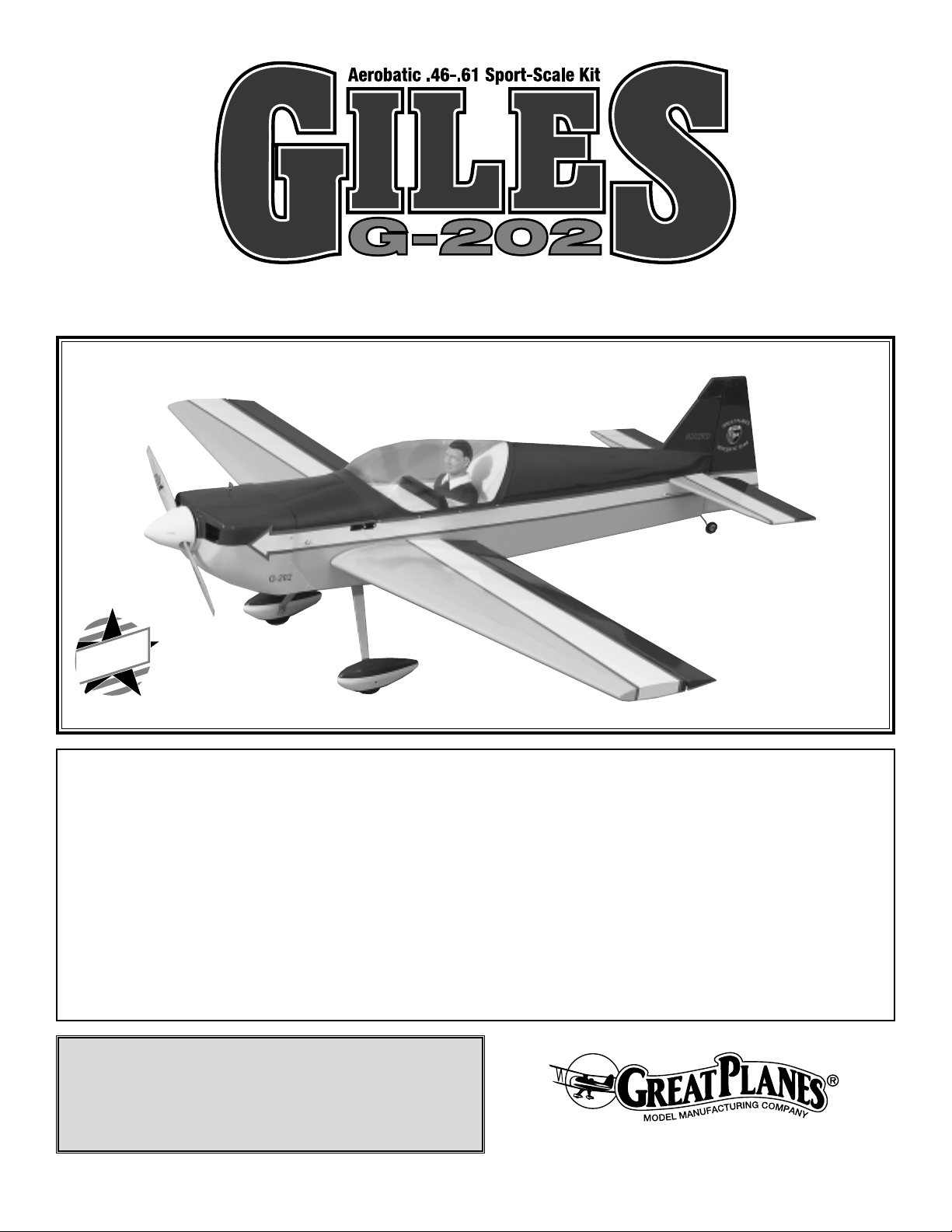
Your Giles G-202 is not a toy, but a sophisticated, working
model that functions very much like an actual airplane.
Because of its realistic performance, the Giles, if not
assembled and operated correctly, could possibly cause
injury to yourself or spectators and damage property.
If this is your first low-wing sport model, we
recommend
that you get help from an experienced, knowledgeable
modeler with your first flights. You’ll learn faster and
avoid risking your model before you’re truly ready to solo.
Your local hobby shop has information about flying clubs in
your area whose membership includes qualified instructors.
You may also contact the national Academy of Model
Aeronautics (AMA), which has more than 2,500 chartered
clubs across the country. Contact the AMA at the address
or toll-free phone number below:
Academy of Model Aeronautics
5151 East Memorial Drive
Muncie, IN 47302-9252
Tele. (800) 435-9262
Fax (765) 741-0057
Or via the internet at: http://www.modelaircraft.org
Designed and Engineered by Michael Cross
Instruction Manual by Michael and AnnMarie Cross
Congratulations and thank you for purchasing the Great
Planes Giles G-202. We’d like to provide you a bit of history
on our selection of this aircraft as the newest release in the
Great Planes scale aerobatic line.
Richard Giles noted a trend in the International Aerobatic
Club (I.A.C.) competition arena toward bigger, heavier,
more costly “super monoplanes,” and he wanted to do
better. The resulting “full-scale” Giles G-200 and G-202
were designed specifically to be reasonably priced, low
wing loading, unlimited level performers on reasonably
priced 4-cylinder engines. Likewise, the Great Planes Giles
G-202 is intended to provide you unlimited level
competition performance with a low wing loading and a
reasonably priced power plant.
We’re honored to be able to feature Mr. Bob Stark’s 1998
Giles G-202 color scheme here on our Giles G-202. Mr.
Stark is an avid I.A.C. competitor, judge and president of
his I.A.C. chapter. Mr. Stark began competing at the
advanced level in 1997, and in 1998 he and his Giles
G-202 earned a position on the US Advanced Aerobatic
Team, striving for the 1999 Advanced World Champion title.
INTRODUCTION
PROTECT YOUR MODEL,YOURSELF
& OTHERS...FOLLOW THIS
IMPORTANT SAFETY PRECAUTION
TABLE OF CONTENTS
2
Page 3
The first time we laid eyes on Mr. Stark’s color scheme, we
found it striking and exceptional for model competition.
When asked about its development, he told us that many,
many hours and 24 months of color schemes displayed
throughout his home led to the selection of the “dramatic
contrast between the bright yellow and the deep blue” and
that his primary concerns were “eye appeal on the ramp
and visibility in the air. I wanted a plane that would look like
a winner sitting on the ramp and one that the judges could
see from any angle in any light.” He feels he succeeded
with his line-setting broad straight stripes for easy judging
and bright contrasts. We agree.
The Giles is a rather “square shaped” airplane with well
defined lines. Coincidentally, this makes it exceptionally
easy to build and cover–especially for a semi-scale sport
model. Framing the model is very straightforward, as most
of the structure features interlocking balsa and lite-ply. The
turtle deck sheeting may look a little intimidating but in
actuality it is quite easy to apply if you follow the
instructions.
Flying the Giles G-202 is a thrilling experience–as it should
be for such an aerobatic model! It doesn’t take much
elevator or aileron throw to put the Giles through its paces.
When you have a feel for your Giles G-202, the throws can
be increased to high rates (illustrated in the instructions) to
really showcase the aerobatic potential. The Giles performs
surprisingly well on a ball bearing, schnuerle ported .46,
and even better on a .61 2-stroke, but seasoned experts
will want to get the most out of the Giles by strapping on a
.91 4-stroke.
We hope you enjoy building and flying your Great Planes
Giles G-202 as much as we did the prototypes.
1. Build the model according to the plans and
instructions. Do
not alter or modify the model, as doing so may result in an
unsafe or unflyable model. In a few cases the plans and
instructions may differ slightly from the photos. In those
instances, the written instructions should be considered
as correct.
2. Take the time to build straight, true and strong.
3. Use an R/C radio system that is in first-class condition,
and a correctly-sized engine and components (fuel tank,
wheels, etc.), throughout the building process.
4. Properly install all components so that the model
operates properly on the ground and in the air.
5. Check the operation of the model before every flight to
ensure that all equipment is operating correctly and that the
model has remained structurally sound. Be sure to check
nylon clevises or other connectors often and replace them if
they show signs of wear or fatigue.
6. If you are not already an experienced R/C pilot, you must
fly the model only with the help of a competent, well
experienced R/C pilot.
Remember: Take your time and follow the instructions
to end up with a well-built model that is straight and
true. Please inspect all parts carefully before starting to
build! If any parts are missing, broken or defective, or if
you have any questions about building or flying this
model, please call us at (217) 398-8970 or e-mail us at
productsupport@greatplanes.com and we’ll be glad to
help. If you are calling for replacement parts, please
reference the part numbers and the kit identification
number (stamped on the end of the carton) and have
them ready when calling.
❏ Four (+) channel radio with five or six servos (twin
aileron servos required, twin elevator servos optional)
Items in parentheses (GPMQ4243) are suggested part
numbers recognized by distributors and hobby shops
and are listed for your ordering convenience. GPM is the
Great Planes brand, TOP is the Top Flite®brand, and
HCA is the Hobbico®brand.
Required Accessories
PREPARATIONS
Engine Selection
There are several engines that will work well in your Giles G-202,
but for unlimited performance we recommend a hot 2-stroke such
as an O.S.
®
.61FX (OSMG0561) or SuperTigre®G61
(SUPG0181). If you prefer a 4-stroke, an O.S. .70 Surpass
™
(OSMG0870) works well and the O.S. .91 Surpass (OSMG0895)
makes unlimited vertical lines a part of every flight experience.
Note: Please see the “Flying” section regarding flutter, propeller
selection and aerobatic performance.
Exhaust System
If you choose to use a 2-stroke engine, you will need an in-cowl
muffler for the best appearance. On our prototype Giles G-202 with
the O.S. .61FX, we used the Slimline #3217 Pitts Muffler
(SLIG2217). With the O.S. Surpass .70 and Surpass .91, we
used the stock exhaust included with the engines, and a Hobbico
®
Exhaust Deflector (HCAP2175).
DECISIONS YOU MUST MAKE
NOTE: We, as the kit manufacturer, provide you with a
top quality kit and great instructions, but ultimately the
quality and flyability of your finished model depends on
how you build it; therefore, we cannot in any way
guarantee the performance of your completed model,
and no representations are expressed or implied as to
the performance or safety of your completed model.
PRECAUTIONS
3
Page 4
❏ (1) Y-harness (HCAM2500 for Futaba
®
) or (2) 12"
servo ex
tensions (HCAM1200 for Futaba) and
computerized radio
Optional radio equipment:
❏ (1) 18" servo extension for rear rudder
mounting location
❏
6th servo, computerized radio and either a Y-harness
or (2) 12" servo extensions for dual elevator servos
❏ Engine – See Engine Selection page 3
❏ Exhaust – See Exhaust System page 3
❏ Spare glow plugs [O.S. #8 for most 2-stroke engines,
(OSMG2691), O.S. Type-F for most 4-stroke engines,
(OSMG2629)]
❏ Propeller (Top Flite Power Point
®
); Refer to your
engine’s
instructions for proper size. Note: We recommend
staying with a six pitch and the appropriate
diameter for your engine to optimize aerobatic
performance on this model
❏ Top Flite Super MonoKote
®
covering (approx. 3 rolls)
– See Covering (page 39)
❏ Fuelproof paint, See Painting (page 39)
❏ Fuel tank 10 oz. (GPMQ4104)
❏ 3' Medium fuel tubing (GPMQ4131)
❏ Nylon reinforced packing tape
❏ 1/4" Latex foam rubber padding (HCAQ1000)
❏ (2) 2-1/2" Wheels (GPMQ4223)
❏ (1) 3/4" Tailwheel (GPMQ4240)
❏ (1) 3/16" Wheel collar (GPMQ4308)
❏ 3" Spinner (GPMQ4530, White)
❏ Pilot (DGA 1/4 scale sportsman pilot used in protype,
DGAQ2010)
❏ Fueling system [Great Planes Easy Fueler
™
, (
GPMQ4160)
or Aluminum Fuel Line Plug, (GPMQ4166)]
❏ 12" Velcro
™
non-adhesive backed hook and loop
material
These are the building tools, glue, etc., that we recommend
and mention in the manual.
We recommend Great Planes Pro™CA and Epoxy.
❏ 2 oz. Pro CA (Thin, GPMR6003)
❏ 2 oz. Pro CA+ (Medium, GPMR6009)
❏ 1 oz. Pro CA- (Thick, GPMR6014)
❏ 2 oz. Pro CA accelerator (GPMR6035)
❏ 6-Minute Pro Epoxy (GPMR6045)
❏ 30-Minute Pro Epoxy (GPMR6047)
❏ Pacer Formula 560 canopy glue (PAAR3300)
❏ Hobby knife [handle (HCAR0105), #11 Blades
(HCAR0311), 100 Qty.]
❏ X-ACTO
®
Razor Saw (XACR2531)
❏ Pliers (Common and Needle Nose)
❏ Screwdrivers (phillips and flat blade)
❏ Small T-pins (HCAR5100)
❏ Medium T-pins (HCAR5150)
❏ Masking tape (TOPR8018)
❏ Plan Protector (GPMR6167)
❏ Groove Tube
™
(GPMR8140)
❏ HobbyLite
™
balsa colored filler (HCAR3401)
❏ Bondo
®
or Squadron white putty
❏ Monofilament line for aligning wing & stabilizer
❏ Builder’s triangle set (HCAR0480)
❏ 1/4-20 Tap (GPMR8105, drill bit included)
❏ Soldering iron and solder
❏ Sealing iron (TOPR2100)
❏ CG Machine
™
(GPMR2400)
❏ Dead Center
™
engine mount hole locator
(GPMP8130)
❏ AccuThrow
™
deflection meter (GPMR2405)
❏ Hand or electric power drill
❏ Drill bits: 1/16", 5/64", 3/32", 7/64", 1/8", 5/32", #18 or
11/64", 3/16", #10 or 13/64", 7/32", 1/4", 17/64"
❏ Bar sander or sanding block and sandpaper (coarse,
medium, fine grit)
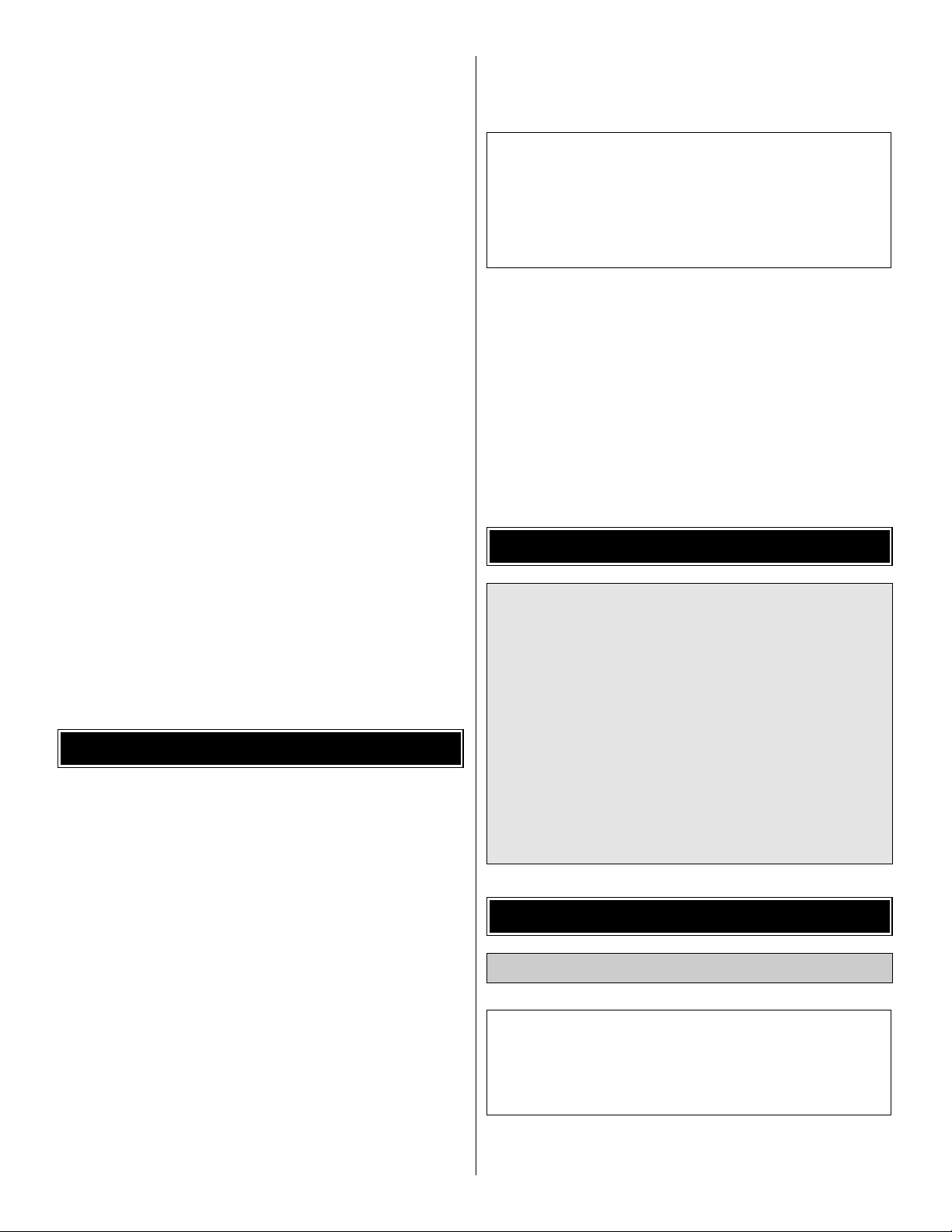
Made of durable, lightweight aluminum, Easy-Touch
Sanders have a uniquely contoured handle that lets you
work longer with less fatigue! The incredibly flat sanding
surface removes high spots with ease. The 5.5" Hand
Sander is ideal for small parts and tight spaces. Use the
11" - 44" Bar Sanders for larger areas. Take the
guesswork
out of sanding curved or angled shapes with the
Easy-Touch Multi-Sander. Available in 11" and 22"
lengths.
Easy-Touch adhesive-backed sandpaper is already
trimmed to these tools’ width...just cut it to length and
press in place. Available in 4 different grits.
GPMR6169 Easy-Touch Hand Sander-5.5"
GPMR6170 Easy-Touch Bar Sander-11"
GPMR6172 Easy-Touch Bar Sander-22"
GPMR6174 Easy-Touch Bar Sander-33"
GPMR6176 Easy-Touch Bar Sander-44"
GPMR6190 Easy Touch Multi-Sander-11"
GPMR6191 Easy Touch Multi-Sander-22"
GPMR6180 Easy-Touch 80-Grit Sandpaper-12' roll
GPMR6183 Easy-Touch 150-Grit Sandpaper-12' roll
GPMR6184 Easy-Touch 180-Grit Sandpaper-12' roll
GPMR6185 Easy-Touch 220-Grit Sandpaper-12' roll
❏ CAApplicator tips (HCAR3780)
❏ Epoxy brushes (GPMR8060)
❏ Epoxy mixing sticks (GPMR8055, Qty. 50)
❏ CA Debonder (GPMR6039)
Optional Tools or Accessories
Building Supplies and Tools
4
Page 5
❏ Clevis installation tool (GPMR8030)
❏ Heat gun (TOPR2000)
❏ Trim Seal Tool
™
(TOPR2200)
❏ Tack Cloth (TOPR2185)
❏ Hot Sock
™
(TOPR2175)
❏ Razor plane (MASR1510)
❏ Single-edge razor blades (HCAR0312, 100 Qty.)
❏ 36" Non-slip straightedge (HCAR0475)
❏ Denatured or isopropyl alcohol (for epoxy clean-up)
❏ Dremel
®
Moto-Tool®or similar w/sanding drum, cutting
burr and cut-off wheel
❏ Curved-tip canopy scissors (HCAR0667)
❏ Servo horn drill (HCAR0698)
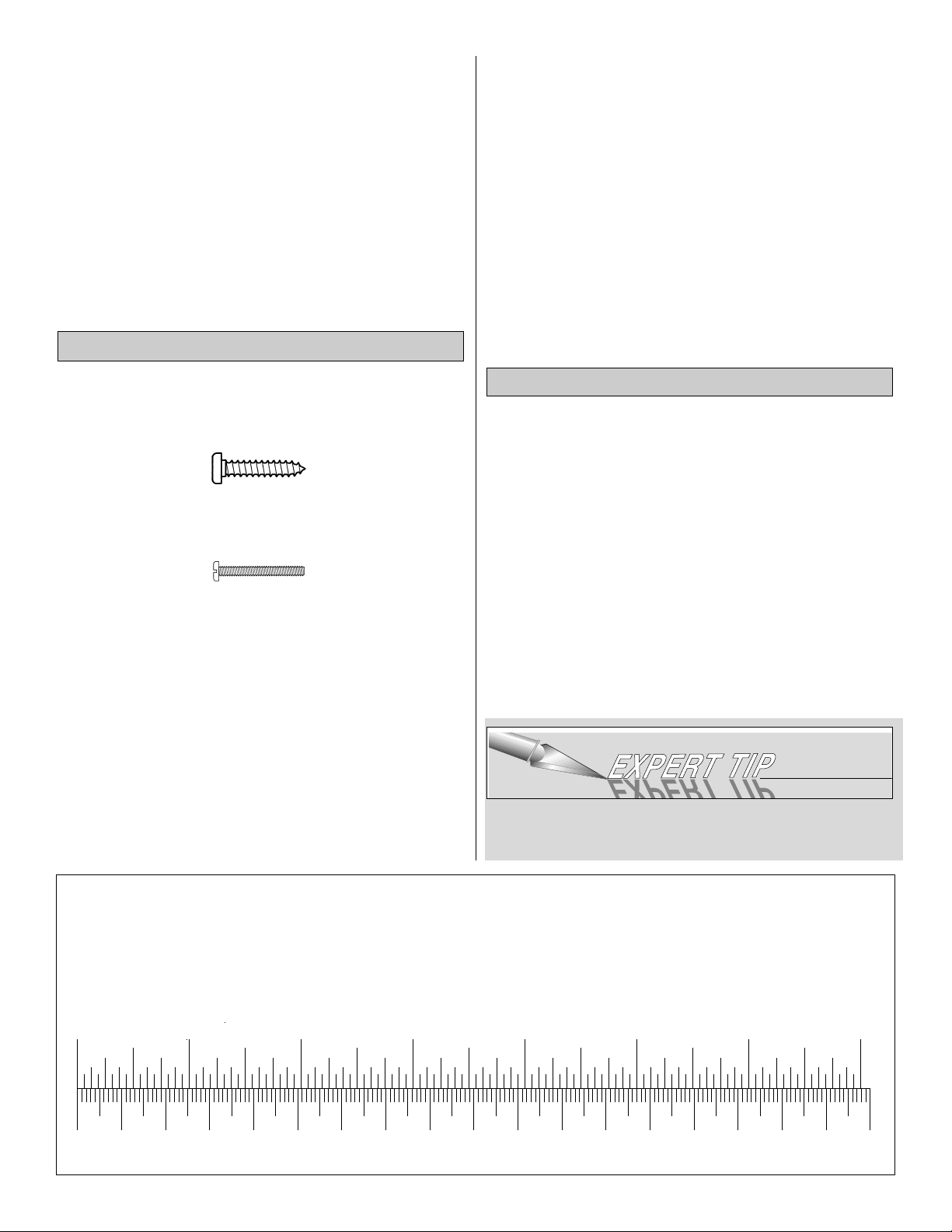
There are two types of screws used in this kit:
Sheet metal screws are designated by a number and a
length. For example #6 x 3/4"
Machine screws are designated by a number, threads per
inch and a length. For example 4-40 x 3/4"
When you see the term “test fit” in the instructions, it means
you should first position the part on the assembly without
using any glue, then slightly modify or “custom fit” the part as
necessary for the best fit. Do not glue until told to do so.
When you see the term “fit” in the instructions, it means you
should first position the part on the assembly without using
any glue, then modify or “custom fit” the part as necessary for
the best fit. Glue when you are satisfied with the fit.
Whenever just “epoxy” is specified you may use either 30-
minute epoxy or 6-minute epoxy. When 30-minute epoxy is
specified it is highly recommended that you use only 30-
minute epoxy because you will need the working time and/or
the additional strength.
Where you see the term “glue,” it is at your option to select the
thickness of CA with which you are most comfortable. If the
step indicates a particular thickness of glue, be sure to use the
thickness recommended for strength, penetration, and/or
working time.
Several times during construction we refer to the “top” or
“bottom” of the model or a part of the model. For example,
during wing construction we tell you to “glue the top main
spar” or “trim the bottom of the former.” It is understood that
the “top” or “bottom” of the model is as it would be when the
airplane is right-side up and will be referred to as the “top”
even if the model is being worked on upside-down (i.e. the
“top” main spar is always the “top” main spar even when the
wing is being built upside-down).
❏ 1. Unroll the plan sheets. Re-roll the plans inside out to
make them lie flat.
❏ 2. Remove all parts from the box. As you do, figure out the
name of each part by comparing it with the plans and the parts
list included with this kit. Using a felt-tip or ballpoint pen, lightly
write the part name or size on each piece to avoid confusion
later. Use the die-cut patterns shown on page 6 to identify the
die-cut parts and mark them before removing them from the
sheet. Save all leftovers. If any of the die-cut parts are
difficult to punch out, do not force them! Instead, cut around
the parts with a hobby knife. After punching out the die-cut
parts, use your bar sander to lightly sand the edges to
remove any die-cutting irregularities or slivers.
❏ 3. As you identify and mark the parts, separate them into
groups, such as fuse (fuselage), wing, fin, stab (stabilizer)
and hardware.
Zipper-top food storage bags are handy to store small parts
as you sort, identify and separate them into sub-
assemblies.
Get Ready to Build
Building Notes
5
0" 1" 2" 3" 4" 5" 6" 7"
0 10 20 30 40 50 60 70 80 90 100 110 120 130 140 150 160 170 180
Inch Scale
Metric Scale
Metric Conversions
1/64" = .4 mm
1/32" = .8 mm
1/16" = 1.6 mm
3/32" = 2.4 mm
1/8" = 3.2 mm
5/32" = 4.0 mm
3/16" = 4.8 mm
1/4" = 6.4 mm
3/8" = 9.5 mm
1/2" = 12.7 mm
5/8" = 15.9 mm
3/4" = 19.0 mm
1" = 25.4 mm
2" = 50.8 mm
3" = 76.2 mm
6" = 152.4 mm
12" = 304.8 mm
18" = 457.2 mm
21" = 533.4 mm
24" = 609.6 mm
30" = 762.0 mm
36" = 914.4 mm
Page 6
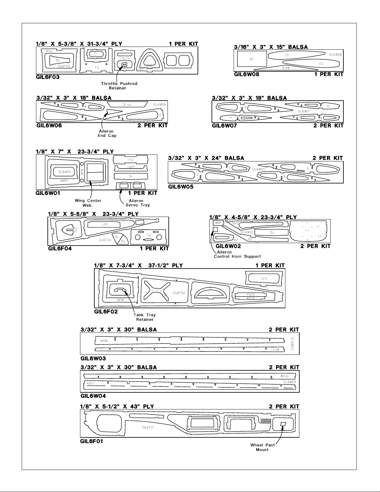
6
DIE-CUT PATTERNS
Page 7
You may remove the stabilizer and elevator drawing from
the wing plan by cutting along the dashed line. Don’t forget
to cover the plan with Great Planes Plan Protector so the
glue won’t stick to the plan.
While the placement of the outer framing of any stick-built
part is important, the exact placement of the internal ribs
is not so critical. It is more important to have the ribs fit
properly between the framework and have strong, secure
glue joints than to have them placed in an exact location.
If you need to slide an internal rib up or down as much as
1/8" within the Giles’ tail framework to gain a snug fit and
a strong glue joint, feel free to do so.
Note: Be sure to save all of the leftover pieces from
building the stabilizer. These pieces will be utilized in
constructing the fin. Construction photos are shown off
the plans for clarity.
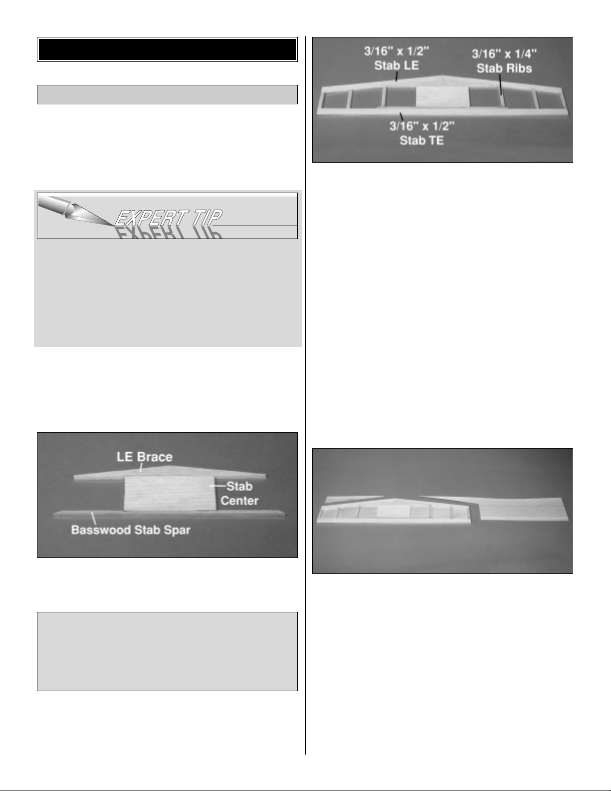
❏ 1. Pin the die-cut 3/16" balsa stab LE brace in position
over the plan. Fit and glue the die-cut 3/16" balsa stab
center.
❏ 2. Position the 3/16" x 3/16" x 10" basswood stab spar
over the plans. Sand the ends to the taper shown. Glue the
stab spar to the rear of the stab center.
❏ 3. Using two 3/16" x 1/2" x 24" balsa sticks, fit and glue
the stab leading edges and stab trailing edge. From a
3/16" x 1/4" x 24" balsa stick, fit and glue the stab ribs. (Be
sure to save the leftover pieces for building the fin.) Note:
Hold a non-slip straightedge behind the stab trailing edge
while fitting and gluing the stab ribs to help ensure a
straight trailing edge.
Hint: Single-edge razor blades work very well for making
clean vertical cuts in sticks such as those used for the tail
framework on this model.
❏ 4. Unpin the stab from the plans. Inspect all glue joints
and re-glue with CA as necessary. Use a bar sander and
220-grit sandpaper to sand the entire top and bottom
surface of the stab framework until it is flat and even. Be
careful while sanding so that you do not over-thin any one
particular area of the stab or gouge the stab ribs by
snagging the sandpaper on them.
❏❏5. Position the stab on a 1/16" x 4" x 30" balsa stab
sheeting, aligning the sheeting with the TE and one end of
the stab. Using medium CA, glue the stab framework to the
stab sheeting.
Note: Give the CA ample time to cure before lifting the
assembly off the building board. It is essential to get a very
secure and uniform bond between the stab sheets and the
stab core, especially in the center.
❏❏6. Place the sheeted side of the stab on the building
board and trim the sheeting around the outer edges of the
framework. Save the remaining pieces.
Note: Refrain from using excessive accelerator. Even
hours after it’s sprayed on, residual accelerator can
prematurely and unexpectedly cure the CA you use later
on nearby glue joints. Unless you must handle or remove
the part from the building board right away, we
recommend using no accelerator at all.
Build the Stab
BUILD THE TAIL SURFACES
7
Page 8
❏7. Repeat steps 5 and 6 to sheet the other side of the
stab.
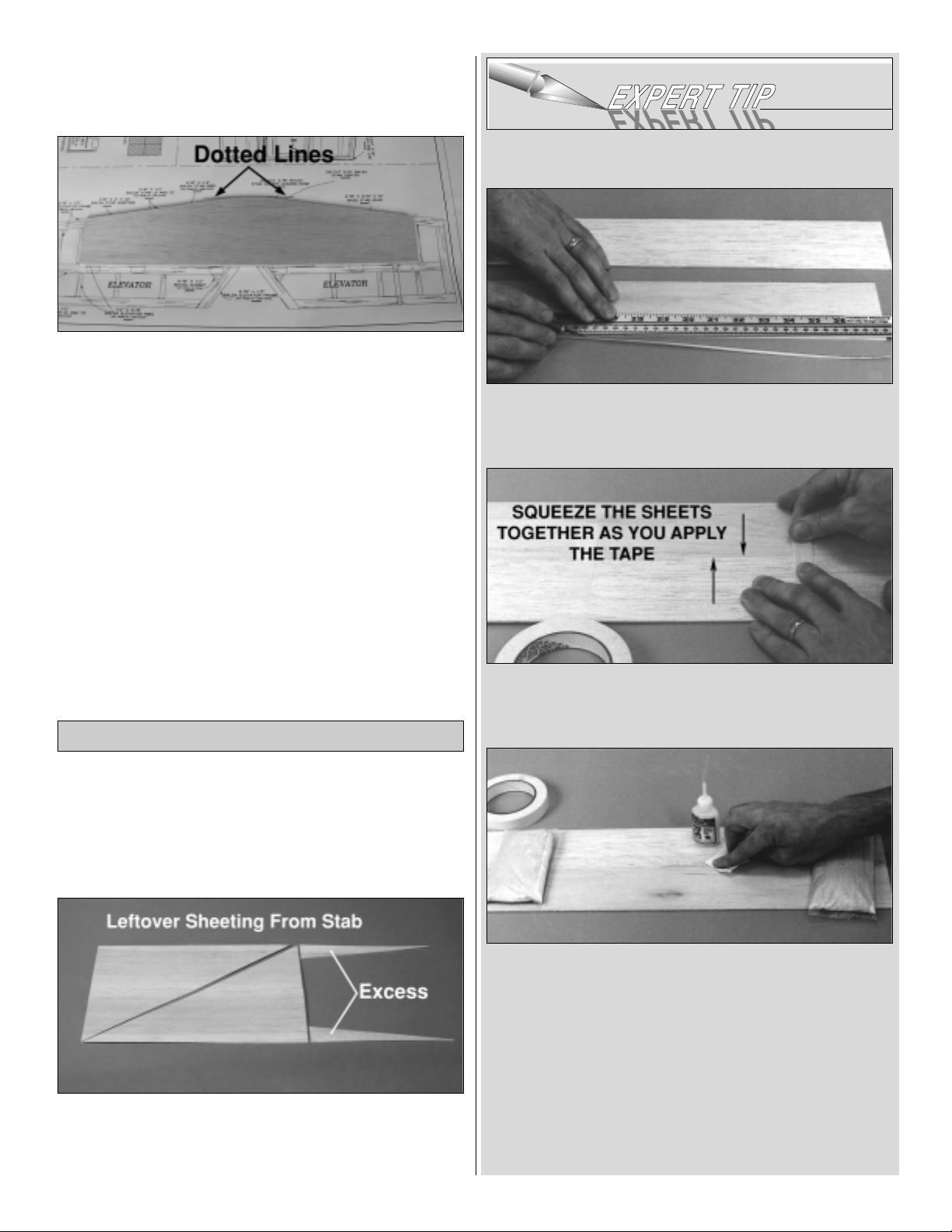
❏ 8. Using the dotted lines on the front of the stab plan as
a reference, sand a flat on the front of the stab.
❏ 1. Remove the stab plan from your building board, and
lay out the fuselage plan. Cover the fin area of the plan with
Great Planes Plans Protector so the glue won’t stick to
the plan.
❏ 2. See the Expert Tip that follows, then use thin CA to
edge glue the two leftover pieces of 4" wide sheeting from
the stabilizer. Cut off the excess sheeting as shown in the
photo. Cut the sheeting diagonally to create two fin sheets.
HOW TO JOIN SHEETING
A. Use a metal straightedge as a guide to trim one edge
of both sheets.
B. Use masking tape to tightly tape the two sheets
together joining the trimmed edges.
C. Turn the sheet over and place weights on top of the
sheet to hold it. Apply thin CA sparingly to the seam
between the two places, quickly wiping away excess CA
with a paper towel as you proceed.
D. Turn the sheet over and remove the masking tape,
then apply thin CA to the seam the same way you did for
the other side.
E. Sand the sheet flat and smooth with your bar sander
and 150-grit sandpaper.
Build the Fin
8
Page 9
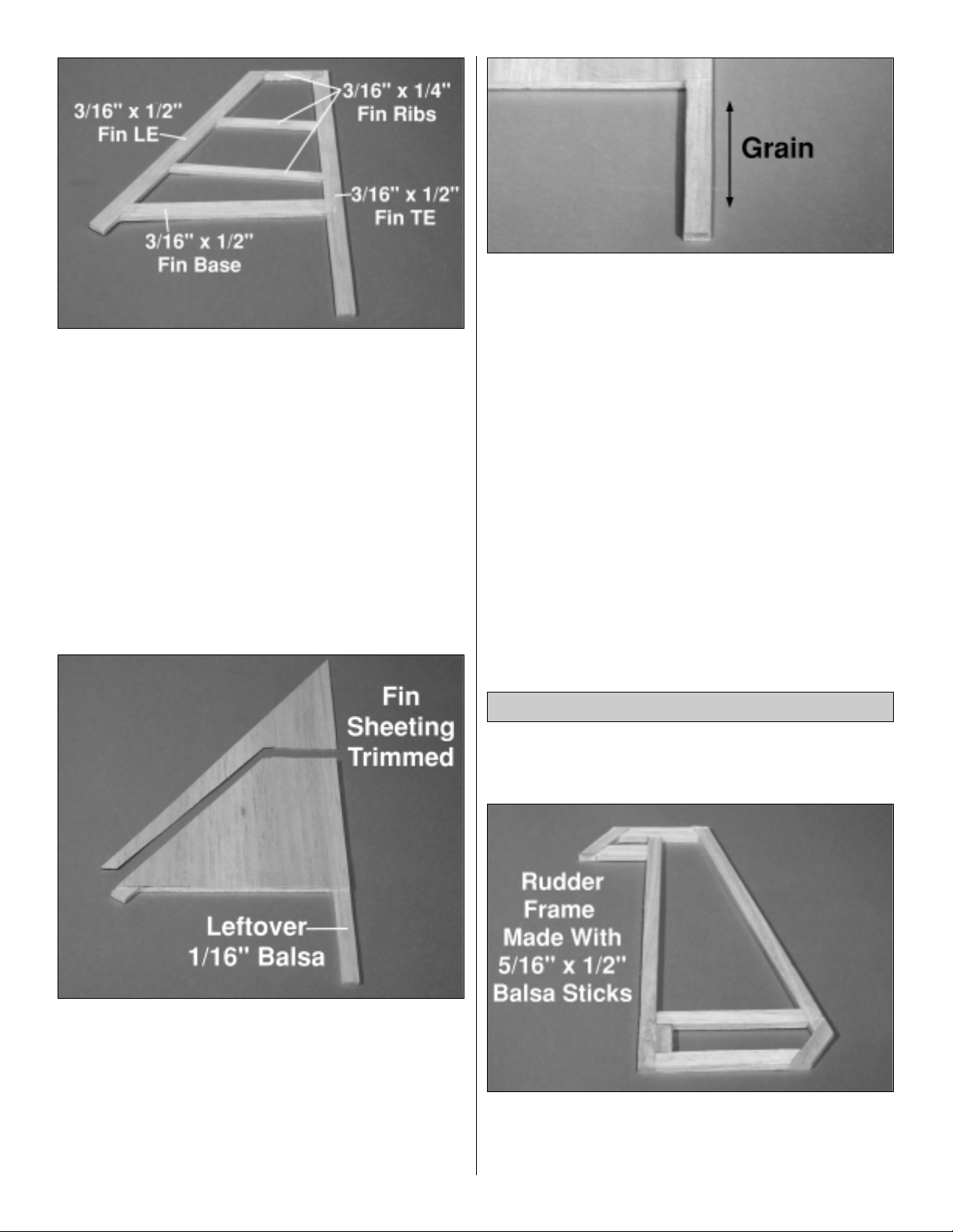
❏ 3. From a 3/16" x 1/2" x 24" balsa stick, cut the fin
leading edge and fin trailing edge. Pin them to the plans.
Using the leftover piece of 3/16" x 1/2" stick from the fin
leading edge, fit and glue the fin base into position.
❏ 4. From the leftover 3/16" x 1/4" balsa stick, fit and glue
the three fin ribs.
❏ 5. Unpin the fin from the plans. Inspect all glue joints,
and reglue with CA as necessary. Sand the left and right
sides until they are flat and even.
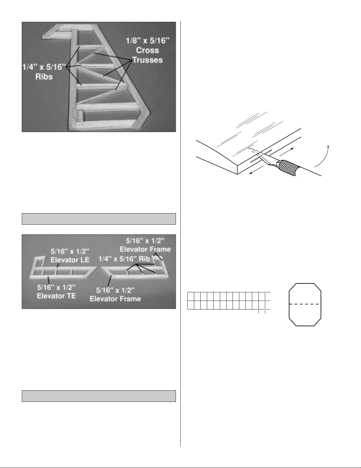
❏❏6. Position the fin on the fin sheeting you made in
step 1, aligning the sheeting with the trailing edge and
fin base. Glue it in place with medium CA.
❏❏7. Place the sheeted side of the fin on the building
board and trim the sheeting around the outer edges of the
framework.
❏❏8. Using leftover 1/16" balsa sheet, sheet the vertical
post with the grain of the balsa running vertically.
❏9. Repeat steps 6, 7 and 8 to sheet the other side of the
fin.
Note: The remaining wood from the fin, stab and elevators
will not be required to complete this model. Now might be a
good time to stash it away in your spare balsa box and dust
the shavings from the building board.
You may remove the rudder drawing from the wing plan by
cutting the drawing along the dotted line.
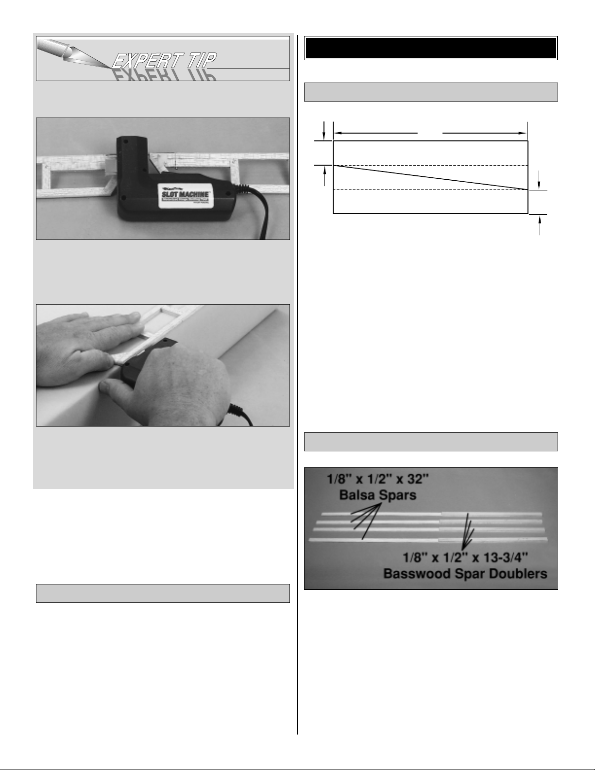
❏ 1. Using a 5/16" x 1/2" x 24" balsa stick, cut the rudder
leading edge and rudder trailing edge. Pin them to the
plans. Use a second 5/16" x 1/2" x 24" balsa stick to make
the rudder frame pieces. Pin and glue them in place.
Build the Rudder
9
Page 10
❏ 2. Using the 1/4" x 5/16" x 24" balsa stick, fit and glue
the three rudder ribs.
❏ 3. Using the 1/8" x 5/16" x 12" balsa stick, fit and glue
the three rudder cross trusses.
❏ 4. Unpin the rudder from your plans. Inspect all glue
joints, and re-glue with CA as necessary. Sand the top and
bottom until they are flat and even.
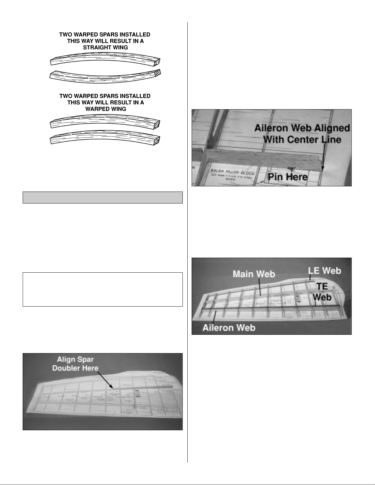
❏ 1. Using three 5/16" x 1/2" x 24" balsa sticks, fit, pin and
glue the elevator leading edge, elevator trailing edge,
elevator frames, and elevator gussets for each elevator
half.
❏2. Using a 5/16" x 1/4" balsa stick leftover from the
rudder,
fit and glue the four elevator ribs for each elevator half.
❏ 3. Unpin the elevators from your plans. Inspect all glue
joints, and re-glue with CA as necessary. Sand the top and
bottom until they are flat and even.
Note: We do not recommend using any pin style hinges on
this model. In the case of hinging your elevators, drilling
deep enough for pin hinges will cause you to drill through
the 3/16" basswood stab spar in the stab, resulting in a
weak point in the structure.
❏❏1. Place the stab over its location on the plan and
lightly mark the hinge locations on the trailing edge with a
ballpoint pen. Mark the hinge locations on the elevators in
the same manner.
❏❏2. Cut the hinge slots in the elevator and stabilizer
using a #11 blade. Begin by carefully cutting a very
shallow slit at the hinge location to accurately establish the
hinge slot. Make three or four more cuts, going a little
deeper each time. As you cut, slide the knife from side to
side until the slot has reached the proper depth and width
for the hinge.
❏❏3. Cut 3/4" x 1" hinges for the elevators and rudder
from the supplied 2" x 9" hinge material, then snip off the
corners. Temporarily join the elevators to the stab with the
hinges, adjusting any hinge slots if necessary so they all
align. Do not glue in the hinges until you are instructed
to do so.
❏ 4. Repeat steps 1 through 3 to complete the procedures
to hinge the rudder and fin.
Hinge the Tail Surfaces
Build the Elevator
10
1"
1"
3/4"
Page 11
Great Planes Slot Machine
™
We have simplified the task of cutting hinge slots with the
introduction of the Great Planes Slot Machine. This
simple electric tool cuts a perfect width slot for use with
CA hinges.
To cut the hinge slot, place the blades onto the wood
where you want the slot. Lightly press the teeth into the
wood. When you are satisfied with the location, press the
button on the handle and the blades will cut easily into the
balsa wood.
❏1. Shape the leading edge of the elevators and rudder to
a “V” as shown on the plans.
❏2. Use a bar sander and 150-grit sandpaper to round the
tail surfaces as shown on the plan.
That’s about it for the tail surfaces. They’re a little more
work than sheet surfaces but they are much lighter, just as
strong, and a nice piece of craftsmanship. Clean off the
building board and get ready for the wing!
Right now, while the building board is clear, is a great time
to assemble the wing sheeting.
❏❏1. Edge glue three 1/16" x 3" x 30" balsa sheets
together. Cut the sheets as shown above, cutting the center
sheet diagonally corner to corner, creating two LE sheets.
❏ 2. Repeat step 1 to build the LE sheets for the second
wing panel.
❏ 1. From the two 1/8" x 1/2" x 30" basswood sticks, cut
four 13-3/4" long spar doublers.
❏ 2. Before using the 1/8" x 1/2" x 13-3/4" basswood spar
doublers, examine them carefully for possible
imperfections. Look for knots, soft spots, diagonal grain and
any other imperfections. If possible, position each spar
doubler so the imperfections (if any) are on the outer half of
the wing panel (toward the tip), where they will be least
affected by high stress. If the spar doublers are warped
slightly, try to “balance them out” by installing the warped
spar doublers in opposite directions (see sketch).
Build the Wing Spars
Assemble the Wing Sheeting
BUILD THE WING
Finish the Tail Surfaces
11
30"
3"
3"
Page 12
❏ 3. Align the end of each spar doubler with the inboard
end of one of the 1/8 x 1/2" x 30" balsa spars. Glue the
spar doublers to the spars. From this point forward we refer
to this combination as a spar.
The construction of these wings is engineered specifically
to provide a perfectly straight and true wing panel with
minimum effort on your part. To do so, the building
sequence and pieces are quite different from what you may
be accustomed to. Be sure to read all steps carefully and
pay particular attention to instructions of when and where to
apply adhesives.
❏❏1. Tape the right wing plan to the building board, and
cover the wing drawing with Great Planes Plan Protector.
Remember, we are building the right wing upside-down
over the right wing bottom view.
❏❏2. Position the top spar on top of the plan with the
spar doubler visible, aligning the end of the spar doubler
with the “ALIGN BASS SPAR DOUBLER HERE” marks
on the plan. The spar will overhang both R-1 and R-11. Do
not cut them at this time. Pin them in place as shown in the
photo. Note: The pins are offset the aft side to leave space
for the main web.
❏❏3. Carefully punch out the four die-cut 3/32" balsa
webs and the die-cut 3/32" balsa wing ribs. Sand the
edges slightly to remove any die-cutting irregularities. Be
careful not to alter the shapes or angles of any of the
pieces.
Note: Do not glue until instructed to do so.
❏❏4. Select the die-cut 3/32" balsa rib R-3, main web,
and aileron web (with support jig attached). Slide R-3 into
its slots in the main web and the aileron web. Align the
main web, centering it on the spars and aligning the notch
on the top of the main web with the spar doubler. Align the
aileron web in position on the plans with the root end flush
with the wing centerline. Pin the root end of the aileron web
in place as shown.
❏❏5. Position R-10 in its slots to lock the webs in place.
Insert all of the remaining ribs except R-2A into their
locations. Note: If you happen to break one of the ribs
during installation, simply take it out of the wing, position
the pieces together and glue with thin CA. Allow to dry and
reinstall.
Designer’s Note: Occasionally outside forces such as
humidity and dramatic temperature changes can result in
slight inaccuracies in the dimensions of printed plans. One
of the many advantages of a fully interlocking wing such as
this one is that exact alignment over a printed plan is not
necessary to ensure a straight wing. If the ribs do not align
perfectly over the plans, don’t worry! As long as the spar
doubler is aligned as shown and the aileron web is aligned
with the centerline of the wing, the wing will be true.
IMPORTANT NOTE: The following instructions explain
how to build the wing directly over the plans. We’ll start
by building the right wing panel upside-down over the
right wing plan so your progress matches the photos.
Build the Wing Panels
12
Page 13
❏❏6. Carefully slide the die-cut 3/32" balsa TE web and
the die-cut 3/32" balsa LE web over the ribs in their
notches until the top of the webs are flush with the top of
each rib. Take your time and be gentle; this balsa structure
is still fragile at this point, but when finished will provide you
a strong, light platform. When everything is aligned, use
thin CA to glue all joints except any joints connecting
to R-1.
❏❏7. Test fit (do not glue) the bottom spar into the ribs,
fitting the spar doubler into the notch in the main web.
When you are confident you can fit the spar in place,
remove the spar. Lay a bead of medium CA along the
bottom of the main web and the corners of the rib slots, and
reinstall the bottom spar.
❏❏8. Use a builder’s square to be sure R-1 is square to
the building board, then glue R-1 to the spars and the webs
with thin CA. Note: Be sure not to press down on the spars.
The top of the top spar must align with the top of R-2A, and
the bottom of the bottom spar must align with the bottom
of R-2A.
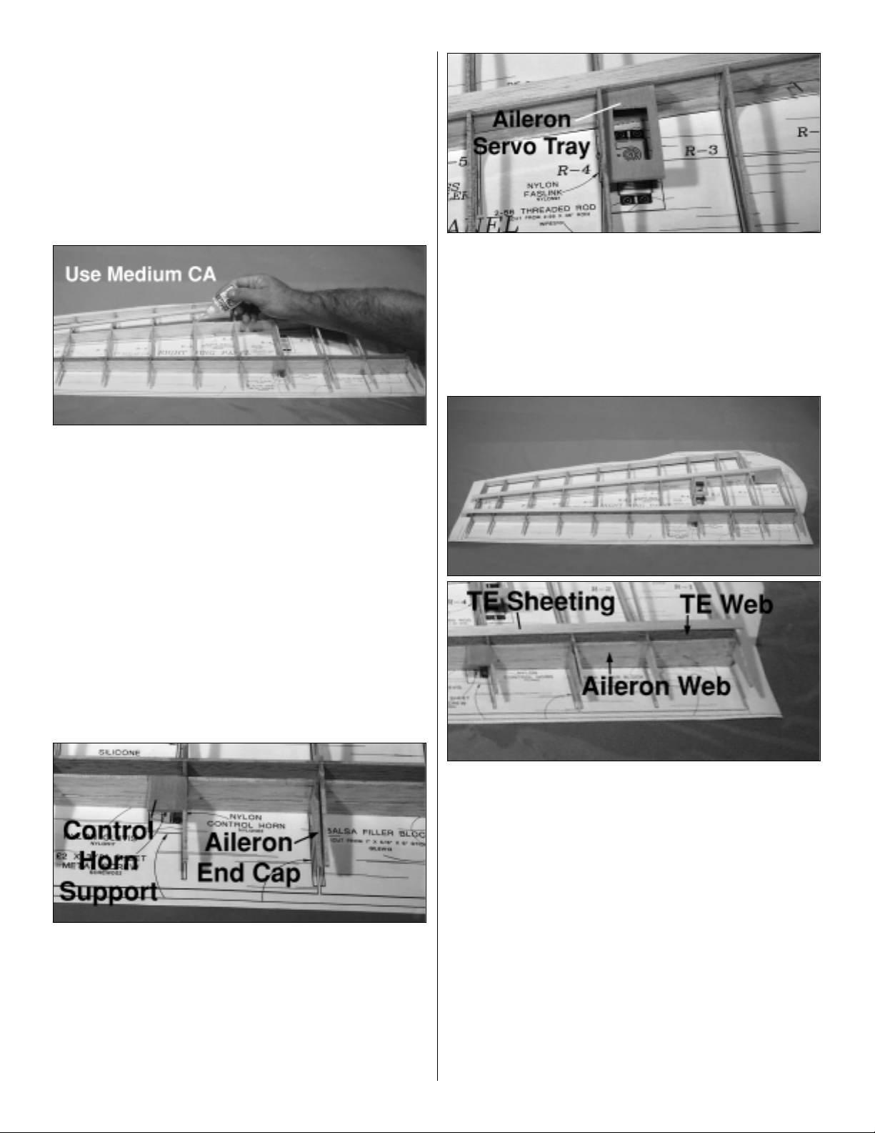
❏❏9. Align and glue the die-cut 1/8" plywood control
horn support to R-4 and the aileron web.
❏❏10. Align the die-cut 3/32" balsa aileron end cap
parallel with R-3 and glue it to the TE web.
❏❏11. Position and glue the die-cut 1/8" ply rib R-2A.
❏❏12. Fit the die-cut 1/8" ply aileron servo tray in the
slot in R-4, holding tight against the top of the bottom spar.
Glue in place with thin CA.
❏❏13. Fit the die-cut 1/8" ply center web tight against
both spars and R-1. Glue in place with medium CA.
❏❏14. Align the 1/16" x 1/2" x 30" TE sheeting with the
back of the TE web, allowing at least 1/8" excess to
overhang each end of the wing panel. (Leaving the excess
will allow you to sand the sheeting perfectly flush with R-1
and the balsa end cap later.) Glue it in place. Hint: Lay the
TE sheeting over the TE web and mark a line along each
rib at the edge of the sheeting. Remove the sheeting and
lay a bead of medium CA along the TE web and the ribs up
to those marks. Reposition the TE sheeting flush with the
TE of the TE web and hold in place until dry.
❏❏15. Select a piece of the 1/16" x 2-3/4" x 24" aileron
sheeting, and carefully true one edge. Do so by aligning a
no-slip straightedge approximately 1/32" down from and
parallel with a long edge of the sheet. Trim the sheeting
along the straightedge, being careful to keep the knife
vertical. Discard the thin piece of sheet you trimmed.
13
Page 14
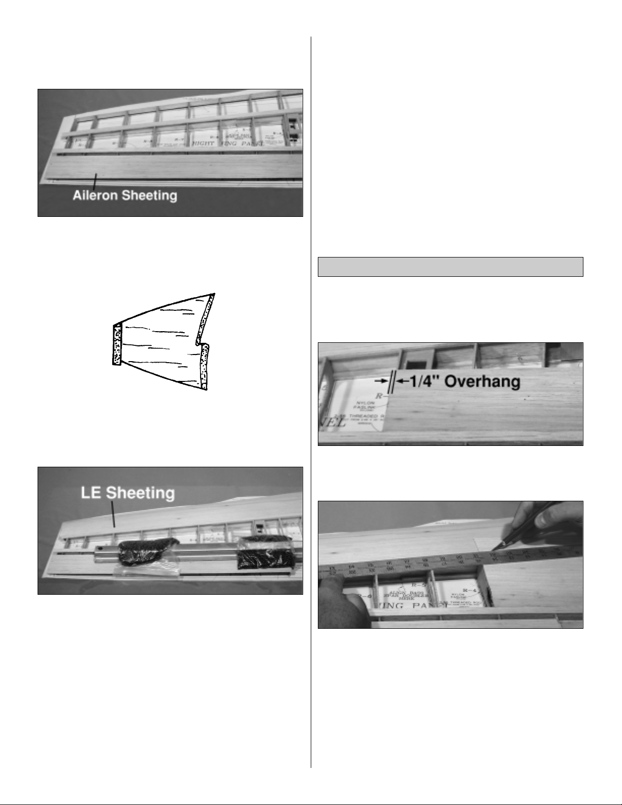
❏❏16. Measure 2-3/8" in from the cut you just made and
cut off the excess sheeting, making a 1/16" x 2-3/8" x 24"
trued aileron sheet.
❏❏17. Place a bead of medium CA along the aileron
portion of each rib, the aileron end cap and the aileron web.
Align the aileron sheeting you just made with the leading
edge of the aileron web and the aileron end cap.
❏❏18. Use a bar sander to shape the LE web so it
aligns with the tops of the ribs and the shape of the airfoil
as shown in the sketch. Be careful not to gouge the ribs or
LE web.
Note: Use this photo for the next three steps.
❏❏19. Weight the wing down directly in front of the
aileron web to keep it flat on the support jig. Hint: An Easy
Touch Bar Sander with a weight on top, or bags filled with
lead shot and sealed shut, makes an excellent wing weight.
❏❏20. Using medium CA, glue a LE sheet to the front
half of the spar. Note: Make sure the sheeting overhangs
R-11 and the center of the wing slightly.
❏❏21. Carefully lift the sheeting away from the ribs, then
apply a bead of medium or thick CA to the top of each rib
and the LE web. Working quickly, pull the sheeting forward
as you press it down to the ribs and the LE web. Use
weights to hold the sheeting to the ribs and LE web until the
CA cures.
❏❏22. Once the glue is dry, lift off the weights and
remove the T-pins from the spars.
❏❏1. From a 1/16" x 3" x 30" balsa sheet, cut two 9-1/2"
long sheets and one 6-1/4" long sheet. These will become
the center sheeting.
❏❏2. Position the first 9-1/2" long sheet over the ribs,
flush with the TE sheeting and overhanging R-4 by 1/4".
Glue in place.
❏❏3. Place the second 9-1/2" long sheet flush against
the first sheet and overhanging R-4 by 1/4". Don’t worry
about it overhanging R-1, we’ll get to that later. Be sure it is
pressed firmly against the first sheet. Lay the straightedge
on the spar, pressed firmly against the trailing edge of the
LE sheeting. Use a hobby knife to carefully cut the second
piece of sheeting along the spar. Remove both pieces of
sheeting and the straightedge from the wing. Glue the
second piece of sheeting in place. Note: You will cut the
opening for the servo after the wing is unpinned from the
building board.
Sheet the Wing Panel Center Section
14
Page 15
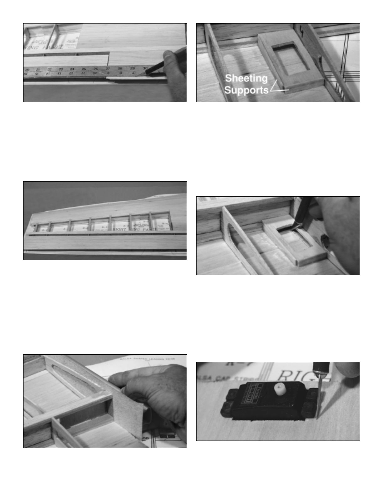
❏❏4. Position the 6-1/4" long sheet flush with the
outboard edge of R-3 (next to, but not touching the aileron
end cap), and pressed against the trailing edge of the TE
sheeting. Lift it off the ribs, lay glue on the ribs and the face
of the TE sheeting. Reposition the sheet and hold in place
while the CA cures. Lay a straightedge on the aileron flush
with the trailing edge of the aileron as shown in the photo.
Carefully trim this sheet along the straightedge.
❏❏5. From 1/16" x 1/4" x 24" balsa sticks, cut and glue
caps strips to the exposed ribs between the LE sheeting
and TE sheeting only. Hint: For easier positioning of the
cap strips, first mark the location of each rib on the LE and
TE sheeting.
❏❏6. Remove the remaining pins and lift the wing from
the building board. Trim everything flush with R-11. Trim the
LE sheeting flush with the front of the LE web.
❏❏7. Trim all of the sheeting flush with R-1. Use a bar
sander to sand the spars flush with R-1. Note: Be careful
not to gouge R-1 and to keep the spar ends square to R-1.
❏❏8. Set the wing right-side up on the building board.
From a piece of leftover sheeting, make a sheeting
support for the inboard side of the aileron servo tray as
shown. Carefully sand the airfoil shape onto the bottom of
the support. Glue with thin CA. Make and glue a second
sheeting support for the trailing edge of the aileron servo
tray. Note: Be careful not to change the shape of the
sheeting when installing these supports.
❏❏9. Use a hobby knife to cut the opening for the servo
in the sheeting, using the servo tray as a guide. Hint: While
the wing is right-side up, use a hobby knife to cut just the
corners of the servo opening. Turn the wing upside-down
again, and use a straightedge to cut straight lines between
the four corners you marked. Remove the piece of
sheeting.
❏❏10. With the wing upside-down, fit the aileron servo in
place and trim the sheeting around the rubber grommets on
the servo. Note: Provide approximately 1/16" of clearance
between the servo and the sheeting.
15
Page 16
❏❏11. Turn the wing right-side up again, and use a
sanding block to shape the LE web so it aligns with the tops
of the ribs and the shape of the airfoil.
Sit back and relax! Take a look at your great work! Enjoy for
just a minute how light and strong this structure is. Okay,
ready to get back to work?
If this is the first time through, go back to the start of Build
the Wing Panels and build the left wing half.
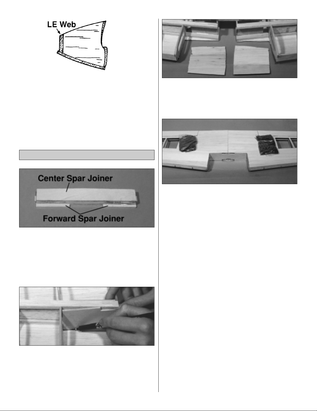
❏ 1. Using medium CA, glue the three die-cut 1/8" ply
center spar joiners together. Center these three layers on
top of the die-cut 1/8" ply forward spar joiner so that the
high point of the center joiners is aligned with the peak on
the center section of the forward joiner. The bottom edge of
the center joiners will also be aligned with the flat edge of
the center section of the forward joiner. Glue them in place.
This complete assembly is now called the wing joiner.
❏❏2. Lay the right wing panel right-side up on the
building board. Hold the wing joiner so the forward spar
joiner is facing you and the flat side of the center section is
up. Write “top” on the front of the forward spar joiner at the
flat edge. Without using any glue, test fit the wing joiner
into its position against the spars. Mark a straight line on
the sheeting where the wing joiner meets the sheeting.
❏❏3. Cut the sheeting along the line drawn in step 2 and
along R-2A, and remove the leftover piece of sheeting.
Repeat steps 2 and 3 for the left wing panel.
Be sure the building board is free of debris and items which
will be in your way, because you’re ready to join the wings!
❏ 4. Lay both panels upside-down as shown in the photo.
Without using glue, test fit the wing halves with the wing
joiner. Some fitting of the wing joiner may be required. Take
your time and be extremely careful that you have a perfect
fit, with no gaps between the spars, and the tabs on the
forward spar joiner locking completely into both R-2Aribs. A
few extra minutes here will help ensure that you have a
strong, true wing that will perform at its optimum. Note: Be
SURE that you have the wing joiner upside-down, just like
the wings are, so that the “top” label is inverted and is just
above the building board as shown in the photo.
❏ 5. When you are confident with the fit and that you can
comfortably position the wing joiner, remove it and lift the
wing halves from the building board. Place a Plan Protector
under the center of the wing to catch excess epoxy. Coat
both R-1s, all four spars, and the wing joiner with 30-minute
epoxy, and install the wing joiner. Place weights on top of
the wing to hold it in place. Do not disturb the wing until the
epoxy is completely cured.
It’s time to take a long, relaxing break and let the epoxy do
its job.
Join the Wing Panels
16
Page 17

❏ 1. Turn the wing right-side up on the building board.
(Notice the dihedral built into the wing, which is flat on top.)
Using a hobby knife, carefully cut the support jigs away
from each wing half. Be careful and take your time, trying
not to break the jig and keeping the cuts straight, even if
you have to cut through some small drops of dried glue
along the way. You will use these jigs for sheeting the top of
the wing, so do not break or discard them.
❏ 2. Cut the 5/8" x 5/8" x 6" balsa stick in half, making two
filler blocks. Position each filler block against R-2 and the
aileron web as shown in the photo. Carve and sand each
block to the shape of the rib airfoil. Glue them in place with
medium CA.
❏ 3. From a 1/4" x 1/4" x 12" balsa stick, cut eight 1-1/2"
long pieces. Center and glue them to the front of the TE
web at the eight hinge locations.
❏❏4. Remove the wing from the building board. Lay out
the right wing panel plan. Pin the jig (cut from the wing in
step 1) on the plans over the aileron web, being sure the
T-pins are at a shallow enough angle so that the pins will
not touch the sheeting when you lay the wing on the jig.
Note: Place the jig so that the narrow end of the jig is at
the tip of the wing plan.
❏❏5. Place the wing with the left wing panel right-side
up on top of the wing jig which is pinned to the right wing
plan. Pin the left bottom spar to the plans. You are now
ready to sheet the top of the wing as you did the bottom.
❏❏6. Align the 1/16" x 1/2" x 30" TE sheeting with the
back
of the TE web, and the centerline of the wing. Glue it in
place.
❏❏7. Select a piece of 1/16" x 2-3/4" x 24" balsa aileron
sheeting, and carefully true one edge of the sheeting.
Measure 2-3/8" in from the cut you just made and cut off
the excess sheeting, making a trued 1/16" x 2-3/8" x 24"
aileron sheet.
❏❏8. Position the aileron sheeting (which you just made)
flush with the leading edge of the aileron web and the
aileron end cap. Glue the sheeting to the aileron end cap,
the aileron web, the aileron ribs, and the trailing edge of the
bottom sheeting.
❏❏9. Use a sanding block to shape the LE web so it
aligns with the tops of the ribs and the shape of the airfoil.
Be careful not to gouge the ribs or LE web.
❏❏10. Weight the wing down directly in front of the
aileron LE web to keep it flat on the support jig.
❏❏11. Using medium CA, glue a LE sheet to the front
half of the spar. Note: Make sure the sheeting overhangs
Finish the Top of the Wing
17
Page 18

the tip rib and is aligned with the centerline of the wing.
Glue the sheeting to the top of each rib and the LE web as
you did with the bottom sheeting. Use weights to hold the
sheeting to the ribs and LE web until the CA cures.
❏❏12. Once the glue has dried, lift off the weights and
remove the T-pin from the spar.
❏❏13. From a 1/16" x 3" x 30" balsa sheet, cut two
9-1/2" long sheets and one 6-3/16" long sheet.
❏❏14. Position the first 9-1/2" long sheet over the ribs,
flush with the LE of the TE sheeting and the centerline of
the wing. Glue it in place.
❏❏15. Place the second 9-1/2" long sheet flush against
the first sheet and flush with the centerline of the wing. Use
a straightedge to trim the second sheet flush with the LE
sheet as you did on the bottom wing sheeting. Glue it in
place.
❏❏16. Position the 6-3/16" long sheet flush with the
outboard edge of R-3 and the centerline of the wing, and
pressed against the trailing edge of the TE sheeting. Glue
the sheet to the ribs, the TE sheeting, and the bottom
sheeting below it. Trim even with the aileron as you did on
the bottom wing sheeting.
❏❏17. From 1/16" x 1/4" x 24" balsa sticks, cut and glue
cap strips to the exposed ribs between the LE sheeting
and TE sheeting only.
❏❏18. Lift the wing from the building board. Trim
everything flush with R-11.
❏❏19. Trim the LE sheeting flush with R-2A, the wing
joiner and the front of the LE web.
❏ 20. Repeat steps 4-19 with the right wing panel right-
side up over the left wing plan.
❏ 21. Glue the die-cut 3/16" balsa wing tips to each R-11
and sand them to match the airfoil shape of R-11.
❏ 22. Separate the shaped leading edges as shown in
the sketch. Leaving 1/4" of shaped LE stock extending
beyond the inboard edge of the left wing’s R-2A and
keeping the shaped LE centered vertically on the LE web,
glue the shaped LE to the front of the left wing with medium
CA. Repeat for the right wing panel.
❏ 23. Trim each LE flush with R-2A and with the wing tips.
Sand both LE’s to blend with the wing, forming a smooth
airfoil shape.
18
Page 19

❏ 24. Using the plans as a reference, cut the servo wire
holes in the top of the wing. Note: Use a nickel as the
template to draw the circles.
❏❏1. Place the wing right-side up on the building board.
Using a razor saw, cut through the aileron web at the root
of the right aileron.
❏❏2. Using a razor saw, cut the ribs and wing tip
between the aileron web and the TE web. Hint: To avoid
confusion later, label the inboard end of the ailerons “right”
and “left” respectively as you remove them.
❏❏3. Carefully trim and sand the aileron ribs and the
wing tip flush with the aileron web. Carefully trim and sand
the ribs and the wing tip flush with the TE web.
❏❏4. Glue the 1/8" x 1" x 24" balsa wing trailing edge
onto the TE of the right wing panel, leaving excess
extending both top and bottom. Sand it flush with the wing
tip and the sheeting, top and bottom.
❏❏5. Glue the 1/4" x 1" x 24" balsa aileron leading
edge onto the front of the right aileron, leaving excess
extending both top and bottom. Sand it flush with the
aileron end cap, and the sheeting, top and bottom.
❏❏6. Bevel and hinge the aileron the same as the
elevator and rudder. Cut the hinge slots in the wing TE and
aileron per the hinge locations shown on the plan.
❏❏7. Position and mount the aileron control horn on
the right aileron using #2 x 3/8" sheet metal screws. Draw a
Finish the Ailerons
19
Page 20

line around the control horn. Remove the screws and the
control horn. Using a hobby knife, poke 12 pin holes in the
top sheeting within the rectangle you drew, then apply a
generous amount of thin CA. Allow the CA to cure,
hardening the balsa, then sand the sheeting smooth. Note:
Use enough CA to have some enter the screw holes;
however, do not use so much that you fill the holes with CA.
❏8. Complete steps 1-7 for the left wing panel.
❏ 1. Place one die-cut 1/8" ply former F-1 on the building
board, punch marks facing up. Glue the second F-1 to the
first with 30-minute epoxy, again with the punch marks
facing up. Make sure the edges all the way around are
aligned. Wipe away excess epoxy before it cures. From
now on this assembly will be referred to as the firewall.
Note: If the formers are warped, simply clamping them
together may not “cancel out” the warps. It is best to clamp
the formers to a table or a flat board until the epoxy cures.
❏ 2. Using a ruler or other straightedge and a pen, draw a
line horizontally across the firewall from the left edge punch
mark to the right edge punch mark. Draw a line vertically
from the top punch mark to the bottom punch mark. The
intersection of these two lines is the center of the engine
mount.
Note: This location is offset for the right thrust built into the
model so that the spinner will still align with the center of
the cowl.
❏ 3. Assuming you are using the included Great Planes
adjustable .60 - 1.20 engine mount, drill the four 7/32"
engine mount holes at the punch marks as shown in the
photo. Drill the two 1/4" fuel line holes and the 3/16" throttle
exit hole as shown in the photo. Note: This throttle exit
placement works for the recommended 2-stroke engines,
clearing the exhaust, as well as 4-stroke engines with the
carburetor rotated 180°. If you are using a different mount,
install it per its instructions, centered on the centerlines you
drew in step 1.
❏ 4. Drill two 1/16" holes through the punch marks in
former F-3. Drill four 3/16" holes through the punch marks
in formers F-5 and F-6. Hint: Place the formers on a scrap
piece of wood and press down as you drill the hole so the
former does not split when drilled.
❏ 5. Press four supplied 8-32 blind nuts into the holes on
the back of the firewall. Gently tap the blind nuts with a
hammer to fully seat them into the firewall. Add a few drops
of thin CA around the blind nuts to secure them.
❏ 6. Lay the two fuselage sides next to each other as
shown in the photo. Glue one die-cut 1/8" ply fuse doubler
to each fuse side, aligned with the wing saddle and the tab.
Label the insides as LEFT and RIGHT. It is important that
you have the fuselage sides in a mirrored position to insure
that you build a left and a right side. Hint: To help you
recognize left from right fuse sides, set the sides upright
and pretend you are in the cockpit.
Assemble the Fuselage
Formers & Sides
BUILD THE FUSELAGE
20
Page 21

❏ 7. Referring to the photo, confirm that you have properly
labeled the fuse sides. Select the right fuse side, and cut off
the tab as shown. Note: The removal of this tab provides
you the appropriate right thrust pre-engineered into the
firewall placement.
❏ 1. Cover the plans with Plan Protector and then pin the
fuse top in position, being sure that the fuse top aligns with
the firewall. Hint: Keeping in mind that the fuse is being
built upside-down, notice the right thrust pre-engineered
into the fuse top and fuse sides.
❏2. Position the die-cut 1/8" ply formers F-3, F-4, F-6 and
F-7 vertically in their slots in the fuse top. Do not use glue
until told to do so.
❏3. Fit the left and right fuse sides to the formers and fuse
top. Do not glue.
❏ 4. Fit the die-cut 1/8" ply aft fuse bottom and mid fuse
bottom in position on the fuse sides and formers.
❏ 5. Use a square to check that the fuse sides are
perpendicular to the building board. Double-check to make
sure each former is square. Using thin CA, glue each
former to the fuse top, bottom and sides. Note: We
selected thin CA due to its excellent penetration and rapid
cure time. After further assembly you will double-check all
the joints and use medium CAas necessary.
❏ 6. Glue the fuse sides to the fuse top and bottom with
thin CA. Leave the fuse assembly pinned to the building
board until the CA has cured, then unpin it from the plans.
❏ 7. Carefully sand the aft fuse bottom and the mid fuse
bottom flush with each other.
❏ 8. Cut one 5-5/8" long wing bolt block from the 1/4" x
1" x 18" birch ply stick. Sand a taper on each end until the
wing bolt block fits precisely in the slots in the fuse
doublers. Note: It is very important that the fit of the wing
bolt block be perfect.
Assemble the Fuselage
21
Page 22

❏ 9. When you are satisfied with the fit, use 30-minute
epoxy to secure the wing bolt block in place in the fuse
doublers and F-4.
❏ 1. Sand the bump off of the die-cut 1/8" ply belly pan
sides as shown in the sketch.
❏ 2. Glue the die-cut 1/8" ply belly pan sides and belly
pan front former perpendicular to the belly pan bottom.
❏ 3. Drill a 13/64" hole through each of the die-cut 1/8" ply
wing bolt plates at the punch marks.
❏4. Test fit and then glue the die-cut 1/8" ply aft belly pan
former and the wing bolt plates in position. Note: The wing
bolt plates must be mounted right-side up. If the wing bolt
plates are inserted right-side up, the aft edges of the two
bolt plates will be in line with one another as shown in the
photo. If they are angled forward, they are installed upside-
down.
❏ 5. Using the aft belly pan former and belly pan sides as
a guide, sand the trailing edge of the belly pan bottom flush
as shown in the photo. Sand the trailing edge of the belly
pan sides flush with the belly pan bottom.
❏ 1. Sand the entire wing saddle area lightly until the fuse
side doublers and fuse sides are flush.
❏ 2. Test fit the wing on the fuse. Center the wing side-to-
side, leaving equal space between the fuse sides and the
wing at the leading edge.
❏ 3. While holding the wing firmly in place and using the
pre-drilled holes in F-3 as guides, drill one 1/4" hole
through the wing joiner. Remove the wing from the fuse.
❏4. Cut the 1/4" x 3" long dowel into two 1/4" x 1-1/2" long
wing dowels. Slightly round both ends of each wing dowel.
Using 6-minute epoxy, glue one dowel in place in the wing,
leaving approximately 7/8" protruding from the front of the
wing joiner. Allow ample time for the epoxy to cure
completely.
Mount the Wing to the Fuselage
Assemble the Belly Pan
22
Page 23

❏5. Fit the wing back onto the fuse, drill the second dowel
hole, remove the wing and epoxy the second dowel in
place. Allow ample time for the epoxy to cure.
❏ 6. Stick a T-pin through the center of the aft end of the
fuselage bottom. Tie a piece of monofilament line to the
T-pin. Pull the string to the TE of the wing tip and put a
piece of masking tape on the string at the wing tip. Mark an
arrow on the tape, then slide the tape on the string so the
arrow aligns with the wing tip. Swing the string over to the
other tip and see if it aligns with the same point. If
necessary, shift the wing and mark the location of the tip by
adjusting the position of the tape on the string. Do this until
the arrow on the string aligns with both tips.
❏ 7. Now that the wing is accurately positioned, align the
belly pan with the fuselage, tight against the wing. When it
is positioned properly, use a few drops of thin CA to tack
glue the belly pan sides to the wing. Be careful to neither
move the wing nor glue the wing or belly pan to the
fuselage.
❏ 8. Remove the wing from the fuselage. Use thin CA to
glue the rest of the belly pan to the wing at all contact
points. Hint: Applying the thin CA from the inside of the
belly pan as shown in the photo helps minimize excess CA
outside of the belly pan which would have to be sanded.
❏9. Holding the wing firmly in place on the fuse, and using
the holes in the wing bolt plates as a guide, drill one 13/64"
hole through each wing filler block (inside the wing) and the
wing bolt block (inside the fuse), keeping the drill
perpendicular
to the wing bolt plates and centered in the holes.
❏ 10. Remove the wing from the fuselage and re-drill both
holes in the wing only to 17/64".
❏ 11. Use a 1/4-20 tap to cut threads in the bolt block in
the fuselage. Hint: A cordless drill triggered at a slow
speed makes a great tap driver.
❏ 12. Harden the threads in the bolt block with thin CA,
then re-tap the threads after the glue is completely dry.
❏❏13. Mount the wing to the fuse with both wing bolts.
Fit the paper tube through the belly pan bottom and
around the head of the left wing bolt, flush against the wing
bolt plates. Glue the paper tube to the belly pan bottom and
wing bolt plate with medium CA. Note: Be careful not to
glue the wing bolts to the wing.
❏❏14. Using a razor saw, cut off the paper tube flush
with the belly pan bottom.
23
Page 24

❏ 15. Repeat steps 13 and 14 to mount the paper tube
over the other wing bolt. Sand the paper tubes flush with
the belly pan bottom.
❏ 16. Turn the airplane right-side up. Cut both wing bolts
off, leaving 1/4" protruding above the wing bolt block. Turn
the airplane upside-down and remove the wing from the
fuse.
❏1. Position and glue F-2 to the fuse sides with thin CA.
❏ 2. From the 1/4" x 1" x 12-3/8" birch ply stick (leftover
from the wing bolt block), cut two 5-3/4" landing gear rails.
Insert the landing gear rails through F-2 and into the
notches in F-3 until they are flush with the bottom of the
aft side of F-3. (A small amount of the landing gear rails
will angle past F-3 into the wing saddle.) Note: Pay special
attention not to warp F-3 when you are inserting the landing
gear rails. F-3 must stay straight.
❏ 3. Use 6-minute epoxy to secure the landing gear rails
into F-2 and F-3.
❏ 4. Position and glue the die-cut 1/8" ply landing gear
plate in place. Note: The landing gear plate glues flat to
the landing gear rails.
❏ 5. After the epoxy has cured completely, carefully sand
the aft end of the gear rails flush with the aft side of F-3 (in
the wing saddle).
❏ 6. Position and glue the die-cut 1/8" ply lower firewall
support and forward fuse bottom with thin CA. Note: The
lower firewall support is installed so that the shorter side
glues to the right fuse side (as shown, on the photo’s right).
❏ 7. Sand the lower firewall support and the forward fuse
bottom flush with each other.
Finish the Bottom of the Fuselage
24
Page 25

❏ 8. Notice that the leading edge of the landing gear legs
are straight, and the trailing edge is tapered. Mark an arrow
on the center of the gear pointing toward the straight side
(leading edge).
❏ 9. Center the landing gear on the fuse and press it tight
against the forward fuse bottom. Using the holes in the
gear as a guide, drill two 3/16" holes through the landing
gear plate and landing gear rails.
❏ 10. Remove the gear and redrill the holes in the landing
gear plate and rails to 7/32". Using the included 8-32 x 3/4"
socket head bolts and a 5/32" hex wrench, mount the gear
and pull the included 8-32 blind nuts into place.
❏ 11. Turn the fuselage right-side up and glue around the
blind nuts with thin CAas you did on the firewall.
❏12. Remove the landing gear.
❏ 13. Double-check all of the glue joints of the entire
fuselage. Reinforce with medium CA as needed.
Before mounting the pushrod tubes and preparing for the
servos for the control surfaces, it’s time to make your
decision about which rudder servo location you are going to
use. If you have selected an engine in the upper power
range of this model, such as a .61 FX or .91 Surpass, we
recommend the rear servo mounting configuration for light
weight, ease of balancing, and also the short, direct control.
However, this decision is entirely up to you. The model will
perform exceptionally well with either rudder servo location.
If you have chosen the tail mounted rudder servo location,
you may opt to leave out the rudder pushrod tube. We
recommend leaving the pushrod tube in the model in case
you change engines and wish to relocate the servo at a
later time.
❏ 1. Locate the die-cut 1/8" ply Former F-5. Holding F-5
so that the pushrod tube holes are horizontal and the
narrower side is toward the mid fuse bottom, position F-5
as shown in the first photo. Slide into position in the
fuselage as shown in the second photo. Be careful not to
slide it so far back that you are forcing the fuse sides apart.
F-5 should fit snugly but not bow the fuse sides. When you
are satisfied with the fit, glue in place. Hint: Remember the
fuse is inverted when positioning this former.
❏ 2. Cut the two 36" dark grey plastic pushrod tubes in
half so you have four 18" lengths. Sand the outside of the
tubes with coarse sandpaper so glue will stick.
❏ 3. Install the four tubes through the guide holes in the
formers. Approximately 1/8" of the tubes should protrude
past the rear edge of the exit slots in the fuselage sides.
❏4. Glue the pushrod tubes to F-5 and F-6 with medium
CA.
Install the Pushrod & Antenna Tubes
25
Page 26

❏ 5. You’re about to mix epoxy to work on the aft end of
the fuselage. Before you do so, test fit the die-cut 1/8" ply
stab base. Lightly sand as needed for a perfect fit.
Temporarily remove the stab base.
❏ 6. Mix 30-minute epoxy, and use some of it to install the
stab base.
❏ 7. Mix the remainder with microballoons to create a
thick, strong, easy-to-sand filler. Epoxy the tubes to the
slots at the aft end of the fuselage. Completely fill the slots
with the microballoons and epoxy. Note: Talcum powder
may be substituted for the microballoons.
❏8. Allow the epoxy in both areas to cure completely.
❏ 9. After the epoxy has cured, use a bar sander and
150-grit sandpaper to sand the outer pushrod tubes and
epoxy filler flush with the fuselage sides.
❏ 1. Test fit the die-cut 1/8" ply tank tray and the die-cut
1/8" ply tank tray retainer. Small adjustments may be
required for a perfect fit. Sand lightly as needed until the
tank tray fits snugly in place with the tank tray retainer,
without bowing formers F-2 and F-3.
❏2. When you are satisfied with the fit, install the tank tray
and retainer. Using the holes in F3 as guides, drill two 1/16"
holes through the tank tray retainer. Insert the #2 x 3/8" flat
head screws through the 1/16" holes in F-3 into the tank
tray retainer. Remove the screws, the tank tray retainer and
the tank tray. Harden the threads in the tank tray retainer by
inserting a drop of thin CA in each hole. Set the tank tray
and retainer aside until you are ready to install the tank.
Note: This will allow the threads to dry completely so the
tank tray retainer can be removed. With the removal of the
two screws, the tank and tank tray will be easily removable
for service, repair or replacement.
❏ 3. Fit and glue the die-cut 1/8" ply servo tray tightly
against the tabs in the fuse sides.
❏ 4. Fit and glue the two die-cut 1/8" ply servo tray
supports to the servo tray and fuse sides.
Installing the Tank Tray & Servo Tray
26
Page 27

❏1. From the 3/8" x 6" balsa triangle stock, fit and glue the
two firewall side supports to the fuse sides with medium
CA.
❏2. Fit and glue the firewall in place with 6-minute epoxy.
❏ 3. Position the die-cut 1/8" ply instrument panel in
place, using the IP gauge to set its angle. Glue the
instrument panel in place with medium CA. Remember that
the gauge is for alignment only, and is not to be glued
in place.
❏ 4. From a 1/8" x 1/4" balsa stick, cut a 7-1/8" piece for
the front deck main stringer. Glue this stringer into the
notches in the firewall and the instrument panel. Save the
leftover piece for the turtle deck main stringer.
❏ 5. From a 1/8" x 1/8" x 24" balsa stick, cut two 6-5/8"
long top gluing stringers. Use a straightedge held on top
of both the firewall and the instrument panel to position the
left top gluing stringer. With medium CA, attach the left top
gluing stringer to the left side of the main stringer.
❏ 6. Glue the right top gluing stringer in place on the right
side of the main stringer.
❏7. From a 1/8" x 1/8" x 24" balsa stick, cut two side
gluing
stringers to fit between the firewall and the instrument
panel on the fuse top. Glue these to the fuse top between
the firewall and the instrument panel approximately 1/16" in
from the outside edge of the fuse.
❏ 8. Select the 3/32" x 4" x 18" balsa sheet and cut into
two 9" sheets, creating the left and right front deck
sheeting.
❏❏9. Lay a bead of medium CA along the joint between
the left side gluing stringer and the fuse top. Tightly press
the left front deck sheeting to the left side gluing stringer
and fuse top. Hold firmly until the CA has cured. Note:
Allow the sheeting to overhang both the firewall and the
instrument panel. You will trim off this excess later.
Build the Front Fuselage Deck
27
Page 28

❏❏10. Liberally wet the left front deck sheeting with an
ammonia/water mix to help it bend. Gradually wrap the
sheeting over the fuse top. Holding it in place, use a hobby
knife to carefully trim the sheeting so that it fits against but
does not bow the main stringer. Apply a bead of medium
CA along the left half of the instrument panel and firewall
and along the joint of the main stringer and the left top
gluing stringer. Press the sheeting firmly in place, ensuring
a tight joint with the firewall and instrument panel. Hold it in
place until the CA cures.
❏11. Repeat steps 9 and 10 for the right front deck
sheeting.
❏ 12. Use a hobby knife to trim the front deck sheeting
flush with the instrument panel and the firewall. Sand the
front deck sheeting flush with the instrument panel, the fuse
sides, and the firewall.
❏ 13. Sand the main gluing stringer flush with the front
deck sheeting. Note: Be careful not to sand through the
sheeting.
❏ 14. Sand the fuse sides flush with the firewall. Sand the
firewall flush with the lower firewall support.
❏ 1. If you have not already done so, make sure the stab
and fin are final sanded to a smooth finish. It will be a little
more difficult to do so after they are glued to the fuselage.
Mount the wing on to the fuselage.
❏ 2. Accurately measure the trailing edge of the stab base
and use a ballpoint pen to lightly mark the center. Use the
same procedure to mark the rear center of the stabilizer.
Mount the wing to the fuselage. Position the stab centered
on the stab base on the fuselage, using the marks you just
made for alignment.
❏ 3. Stand about six to ten feet behind the model and see
if the stab is parallel with the wing. If necessary, use a bar
sander to make slight adjustments by sanding the stab
base until the stab is in alignment with the wing.
Mount the Stabilizer to the Fuselage
28
Page 29

❏4. Place the stab on the stab base with the center marks
aligned, then use a large T-pin to attach only the trailing
edge of the stab to the stab base.
❏ 5. Stick a T-pin through the front deck main stringer
above the instrument panel, then use the “pin and string
technique” used on page 23 for aligning the wing, to
accurately align the stab with the fuselage. Once the stab is
accurately aligned, pin the LE of the stab to the stab base.
❏ 6. Carefully turn the fuselage over and use a ballpoint
pen to lightly mark where both fuselage sides contact the
bottom of the stab.
❏ 7. Remove the stab from the stab base but leave the
T-pins in the stab. Apply a film of 30-minute epoxy to the
stab base and to the stab between the lines you marked
indicating the fuselage sides.
❏ 8. Reposition the stab on the stab base and reinsert the
T-pins into the same holes. Use the pin and string to
confirm the stab alignment, then use weights, more T-pins
or clamps to hold the stab in position. Wipe away excess
epoxy before it cures. Recheck alignment, then do not
disturb the model until the epoxy cures.
❏ 1. Measure the center point of the instrument panel
where it meets the fuse top, and make a short line from this
point aft on the fuse top. Measure 5/32" to the right, and
draw a parallel line. Measure 5/32" to the left and draw a
parallel line.
❏ 2. Position the fin as shown on the plans, using a long
straightedge lined up with the marks you made in step 1 to
ensure the fin is precisely aligned at the fuse centerline.
Use a builder’s triangle to check that the fin is
perpendicular to the stab when the lower portion of the fin
TE is clamped between the fuse sides. Mark the stab on
both sides of the fin.
❏ 3. Using 30-minute epoxy, glue the fin in place, double-
checking that it’s perpendicular and aligned with the
centerline of the fuse. Clamp the fin in place within the fuse
sides and allow the epoxy to dry completely. Note: Be sure
no epoxy ran onto the clamps, attaching them to the
airplane.
Enjoy a good cup of coffee, and relax a while! Look at your
awesome workmanship.
❏ 1. Remove the wing from the fuselage and set the fuse
right-side up on the building board. Position the die-cut 1/8"
ply former TD-1 in its notch in the fuse top, using the die-
cut 1/8" ply TD gauge to set TD-1 at the correct angle.
Glue TD-1 in place. Note: The gauge is used only for
setting the angle (do not glue the gauge in place).
❏ 2. Use a square to position the die-cut 1/8" ply formers
TD-2 and TD-3 vertically, at 90° to the fuse top.
❏ 3. Locate the 1/8" x 1/4" balsa stick leftover from the
front deck main stringer. Cut an angle on one end so that
when it is placed into former TD-3, the end is flush with the
front of the fin as shown in the photo. Glue this turtle deck
main stringer to formers TD-1, TD-2, TD-3 and the fin.
Build the Turtle Deck
Mount the Fin to the Fuselage
29
Page 30

❏❏4. Just as you did for the front deck, select a 1/8" x
1/8" x 24" balsa stick. Cut a left top gluing stringer to fit
from TD-1 to TD-2 against the turtle deck main stringer.
Use a straightedge held on top of both TD-1 and TD-2 to
position the left top gluing stringer. With medium CA, attach
the left top gluing stringer to the left side of the turtle deck
main stringer.
❏5. Repeat step 4 for the right top gluing stringer between
TD-1 and TD-2 and for the left and right top gluing stringers
between TD-2 and TD-3.
❏❏6. Position a 1/8" x 1/8" x 24" balsa stick, the left
side gluing stringer, into the notch in the TD formers and
beginning 1/8" past the trailing edge of the stab. The
stringer should be approximately 1/16" recessed from the
fuse sides. Cut the left side gluing stringer flush with the
leading edge of TD-1. Glue it in place with thin CA. Note:
Use thin CA sparingly on the stab, as thin CA wicks through
balsa easily, and saturated sheeting is difficult to sand.
❏7. Repeat step 6 for the right side gluing stringer.
❏ 8. Edge glue three 3/32" x 3" x 24" balsa sheets
together, making a 9" x 24" main sheet. Lay the sheet on
the building board and cut the two turtle deck sheets as
shown on the sketch.
❏❏9. Position one of the turtle deck sheets on the left
side of the fuselage as shown. Note: The grain is running
parallel to the turtle deck main stringer (not the fuse side).
The front is aligned with the bottom leading edge of TD-1,
and the bottom edge is butted against the fuse top and
along the gluing stringer.
❏❏10. Using a hobby knife, carefully trim the inner edge
of the sheeting where it contacts the fin so that when the
sheeting is pressed firmly against the fin the angle makes a
good gluing seam.
❏❏1 1. Wet the outside of the sheeting with a
water/ammonia
mix. Gradually bend the sheeting over the formers and
check the fit of the top seam along the gluing stringer and
flush against the main stringer. Trim as needed for a tight,
clean fit.
❏❏12. Using medium CA, glue the turtle deck sheeting
to the vertical fin, TD-1, TD-2, TD-3, the main and gluing
stringers. Hint: This is easiest to do in sections. Glue the
sheeting to TD-3 and the fin. Then glue to the main and
gluing stringers from TD-3 to TD-2 and also to TD-2. Then
glue to the main and gluing stringers from TD-2 to TD-1
and also to TD-1.
30
1-3/16"
5-1/8"
5-1/8"
1-3/16"
Page 31

❏❏13. Trim the sheeting, the main and gluing stringers
flush with TD-1. Trim the sheeting flush with the trailing
edge
of the fin.
❏14. Repeat steps 9-13 for the right side.
❏15. Sand the turtle deck smooth to the shape shown on
the
cross-section. Sand the leading edge flush with TD-1 and
the trailing edge flush with the fin. Note: Don’t worry if you
have any small gaps along the main stringer. Now is a good
time to fix these little blemishes with some hobby filler.
❏ 1. Select the two die-cut 3/32" balsa IP-2 instrument
panels. Holding them vertical to the building board
positioned 1/2" apart, use leftover sheeting to sheet
between the two IP-2s, creating the pilot’s instrument
panel. To make covering the cockpit floor easier, installation
of this panel will be completed after covering, as shown in
the second photo above. Fact: In an aerobatic plane such
as the G-202, as with many light planes, the rear seat is for
the pilot and the forward seat is for the passenger. This
second seat is carefully positioned very close to the CG of
the aircraft, so that the additional weight of the passenger
does not alter the aircraft’s CG.
Wow! Step back and take a good look. Pat yourself on the
back! You are completely finished framing your Giles
G-202! Nice work.
❏1. Cut the “spreader bars” from the supplied Great
Planes
engine mount, then use a hobby knife to remove any
flashing leftover from the molding process so that the
halves fit together well.
❏ 2. Temporarily attach the engine mount to the firewall
with four 8-32 x 1-1/4" socket head bolts and #8 flat
washers. Do not tighten the screws all the way, because
you still need to adjust the mount.
❏3. Place the engine on the mount and slide the halves in
or out until the engine fits properly. Position the mount so
the molded-in “tick marks” are equally spaced on the
horizontal centerline you drew on the firewall. When the
engine mount is adjusted and positioned, tighten the
mounting screws.
❏ 4. Position the engine on the mount so the drive washer
(or the back of the spinner) is 5-1/4" away from the firewall
and clamp it in place.
Mount the Engine
Finish the Cockpit
31
Page 32

❏ 5. Use the Great Planes Dead Center
™
Engine Mount
Hole Locator to mark the locations of the bolt holes.
Remove the engine from the mount and drill four 7/64"
holes. Tap the engine mount with a 6-32 tap for the 6/32
x 3/4" socket head engine mounting bolts.
❏ 1. Select the 11-3/4" grey outer pushrod guide tube for
the throttle. Use coarse sandpaper to roughen the outside
of the tube so glue will stick. Slide it through its hole in the
firewall and use medium CA to glue it into the firewall. Cut
the pushrod outer tube flush with the outside of the firewall.
Position the die-cut 1/8" ply throttle pushrod retainer in
place against F-3, using a ruler to ensure that it does not
protrude into the wing saddle. Glue in place with thin CA.
❏ 2. Mount the throttle servo as shown on the plans in the
right side of the servo tray.
❏ 3. Install a nylon clevis to the 17-1/2" throttle pushrod
wire. Slide the throttle pushrod through the pushrod tube
with the clevis on the servo end. Without attaching the
clevis to the servo, bend the pushrod as needed to make
the pushrod move smoothly and the clevis properly reach
the servo arm.
❏ 4. Bend and/or cut the engine end of the throttle
pushrod as needed to fit the engine installation, using the
drawing on the fuselage plan as a guide. Make adjustments
to the bends in the wire so the pushrod aligns with the
carburetor arm on the engine, then temporarily connect the
pushrod to the carb arm with whatever connection type you
have selected for the throttle. (We recommend a Great
Planes Screw-Lock Pushrod Connector, not included, for
the throttle connection for ease of use and adjustment.)
Temporarily mount the muffler and make sure the throttle
pushrod will not interfere with the muffler. Make
adjustments to the bends in the wire if necessary. Note:
Because of the close tolerances between the servos and
the wing, do not use Screw-Lock Pushrod Connectors on
the pushrods at the servo.
❏ 5. Thread a nylon clevis onto the 36" pushrod wire
(threaded on one end) for the rudder pushrod. Slide the
pushrod wire through the rudder pushrod guide tube, which
is the lower guide tube on the left side of the fuselage.
Remove the backing plate from a nylon control horn and
connect the horn to the clevis in the outer hole. Fit the
rudder to the fin, using the hinges to hold them in place.
DO NOT GLUE THE HINGES IN PLACE.
At this point, you MUST choose your rudder servo location.
If you are installing anything but the lightest of engines in
the recommended range, we recommend the aft rudder
location to assist in balancing the model, as well as
providing very short, tight rudder linkages for optimal
performance. If you are using the forward rudder servo
location, complete steps 5 through 8. If you are using the
optional rear-mounted servo location, mount and hook up
your rudder servo, using the plans as a guideline, and
remembering that you will need to move the control horn
and cut the pushrod to the appropriate length.
Install the Servos & Make
the Pushrods
32
Page 33

❏ 6. Position the control horn on the rudder as shown in
the sketch and on the plan. Use a ballpoint pen to mark the
location of the control horn mounting holes and drill 3/32"
holes at the marks. Temporarily mount the control horn to
the rudder with the backing plate and 2-56 x 5/8" screws.
❏ 7. Position the rudder servo in the left side of the servo
tray as shown on the plans, using a long servo arm
included with your radio to position the servo so that the
end of the servo arm lines up with the pushrod. Mount the
servo. Note: Be sure the servo is positioned as shown with
the servo shaft toward the aft end of the fuselage to allow
clearance when the wing is attached.
❏ 8. Neutralize the rudder (clamping the counterbalancer
to the fin, using balsa pads to keep from damaging the
rudder, works well) and be sure the servo arm is
perpendicular to the servo case. Cut the pushrod off 1/2"
behind the servo arm. Slide a solder clevis onto the
pushrod at the rudder servo. Attach the clevis to the outer
hole on the servo arm and mark the pushrod with a marker
at the aft edge of the clevis. Note: Leave the clevis and
pushrod installed until after you mount the elevator servos
to ensure proper clearance.
❏ 9. Fit the elevators to the stabilizer, using the hinges to
hold in place. Do not glue. Note: If you wish to use twin
elevator servos, you will need to adjust the next few steps
accordingly to make them fit and mount the clevises, etc. If
you choose twin elevator servos, a computer radio with
appropriate mixing functions is REQUIRED, as the servo
arms must be mounted both facing inboard for the
pushrods to function properly.
❏ 10. Thread a clevis onto one end of each 35" pushrod
wire (threaded on both ends) for the elevator pushrods.
Slide each pushrod through the elevator pushrod guide
tubes, which are the upper guide tubes on each side of the
fuselage. Remove the backing plates from two nylon
control horns and connect the horns to the clevises in the
outer holes. Position and temporarily mount the elevator
control horns as you did the rudder control horn.
❏ 11. Position the elevator servo in the servo tray as
shown on the plans, using a medium servo arm included in
your radio to position the servo so that the end of the servo
arm lines up centered between the two pushrods. Mount
the servo. Note: Be sure the servo is positioned as shown
with the servo arm toward the aft end of the fuselage to
allow clearance when the wing is attached.
❏ 12. Neutralize both elevators (clamping them to the stab
and using balsa pads to keep from damaging them) and be
sure the servo arm is perpendicular to the servo case. Cut
one pushrod 1/2" behind the servo arm; cut the second
pushrod off 1" behind the servo arm. Save the two leftover
pieces for the ailerons. Note: The two elevator pushrods
will not be joined until final assembly, after the model is
covered.
❏ 13. Slide the solder clevis onto the longer pushrod, clip
the solder clevis onto the servo, and mark as you did the
rudder pushrod.
❏ 14. Remove all three pushrods and both solder clevises
from the aircraft. Position the nylon bushings, equally
spaced, onto the wire pushrods. Note: The longest pushrod
33
Correct Incorrect
Page 34

is marked and is for the rudder; the second longest is
marked and is the elevator pushrod with the solder clevis;
the shortest is the second elevator pushrod.
❏ 15. Remove the solder clevises from the servo arms.
The pushrods must be cleaned prior to soldering. Rubbing
alcohol works well for this, but don’t wipe off the marks.
Silver solder the clevises to the pushrods, using the marks
you made for reference.
❏ 16. Mark the location of the tail gear wire on the rudder
and the nylon tail gear bearing on the fuselage, aligning the
bottom edge of the nylon tail gear bearing and the aft fuse
bottom.
❏ 17. Remove the rudder and elevators from the model.
Using a pen, draw lines around the control horns after
which the horns may be removed. Poke approximately a
dozen holes at each surface’s control horn location with the
tip of a hobby knife. Remove the hinges from each surface,
then use thin CA to harden the wood inside the lines you
drew where the control horns attach.
❏18. Drill a 7/64" hole 5/8" deep in the leading edge of the
rudder at the mark you made for the tail gear wire. Cut a
groove in the rudder for the nylon tail gear bearing. The
Great Planes Groove Tube™works great for this task. Test
fit the tail gear wire in the rudder. Cut a slot in the trailing
edge of the fuse at the marks you made for the nylon tail
gear bearing. Without using any glue, test fit the rudder to
the fin with the tail gear wire. When satisfied with the fit,
remove the rudder and set it aside.
❏ 19. Mount the aileron servos in the wing with the screws
provided with your radio. Mount the aileron control horns
back on the ailerons.
❏ 20. Thread the clevises onto the pushrod wires leftover
from the elevators.
❏ 21. Connect the clevis to the control horn. Center the
aileron and position the servo arm perpendicular to the
servo case. Mark the pushrod where it crosses the servo
arm. Bend the pushrod up 90° at the mark and connect it to
the servo arm from the bottom with a nylon Faslink™. Trim
the excess wire that protrudes past the nylon Faslink. Hint:
For a precise pushrod fit, enlarge the selected servo arm
hole with a 5/94" drill bit set.
❏ 1. Using nylon reinforced packing tape, secure the tank
to the tank tray. Using a 1/16" drill bit, drill out the middle
nipple on the Great Planes 10 oz. tank (not included).
Attach a 12" piece of fuel tubing to the upper nipple, and
cap the line with a Great Planes Aluminum Fuel Line Plug
(not included). This will be the line to fill and drain the
model. Note: This system is extremely simple, lightweight,
and inexpensive. It also allows you to completely drain the
model by simply using the fill line while the model is
inverted in a plane stand.
❏ 2. Attach a 12" piece of fuel tubing to the middle nipple,
which will attach to the muffler pressure tap. Assemble and
install the tank cap. Attach a third piece of 12" fuel tubing to
the main nipple in the center of the tank cap, which will
attach to the carburetor.
Assemble & Install the Tank
34
Page 35

❏ 3. Drill a 1/4" hole in the side of the fuselage as shown
in the photo. Harden the wood around the hole with thin
CA. This is the exit location for the fill/drain line. Note: To fill
the model, simply have the model sitting upright on its gear,
gently pull the fuel line out of the model a few inches,
remove the fuel line plug, and fill through the fuel line. To
drain the model, simply leave the model inverted in a plane
stand. Pull the fuel line out, remove the fuel line plug and
drain the fuel tank.
❏❏1. Trim one matching set of wheel pant halves along
the molded cut lines. Notice that the top of the outer pant
goes over the lip of the inner pant and the bottom of the
inner pant goes over the lip of the outer pant. You can use
a hobby knife to carefully score along the cut lines and flex
the plastic until the excess breaks free, or use small
scissors to cut along the lines. Hobbico Curved Tip Canopy
Scissors work extremely well for this and make the job a
cinch. For now, don’t worry about accurately cutting out the
opening in each wheel pant half–just cut an approximate
opening for the wheels.
❏❏2. Use your bar sander to carefully true the edges of
the overlapping pieces of the wheel pant halves so when
you glue them together the seam will be as small and
straight as possible. Notice that the front and rear of the
pant halves do not overlap and are "butt glued" together.
Use 150 or 220-grit sandpaper to remove the flashing and
thoroughly roughen all areas that are to be glued including
the indentation on the inside of both inner pant halves.
❏❏3. Test fit the wheel pant halves together and make
adjustments where necessary for the best possible fit.
❏❏4. Join the wheel pant halves and carefully spot glue
them together in just a few places with thin CA. Start by spot
gluing the top, then the front and rear where the two halves
just butt together. After the halves are joined, securely glue
them together along all seams with thin CA.
Note: Do not use CA accelerator on the ABS plastic as it
may develop cracks and/or keep the paint from adhering.
❏❏5. Use your hobby knife (or a Moto-Tool with a sanding
drum) to finish cutting out the wheel opening.
Hint: Make the wheel opening wide, as this will make
installing the wheels and axles easier and cause less
interference with the wheels upon landing and takeoff. You
can see the size of the wheel openings in the following photo.
❏❏6. Use medium CA to glue the die-cut 1/8" plywood
wheel pant mounts to the inside of the wheel pant.
❏❏7. Use a metal file to chamfer the edges and corners
of the aluminum landing gear so it will neatly fit in the
recess of the wheel pant. Position the wheel pant on the
aluminum landing gear, then use a felt-tip pen to accurately
mark the location of the axle mounting hole.
❏❏8. Drill a 3/16" (11/64" or #18 for precision) hole in
the wheel pant at the mark. Back up the wheel pant mount
with a piece of scrap wood so you do not split it as the drill
goes through.
Assemble the Wheel Pants
35
Page 36

❏❏9. Most 2-1/2" wheels (not included) are made to fit
5/32" axles, but the 8-32 screws supplied in this kit for the
axles require a larger hole. If the wheel does not roll freely
on the 8-32 x 1-1/2" SHCS "axle," enlarge the wheel hub
with an 11/64" (#18 for perfection) drill.
❏❏10. Test fit the wheel in the wheel pant using the
following procedure:
A. Install an axle in a wheel. Thread an 8-32 nut about 1/8"
onto the axle.
B. Insert the wheel in the pant with the end of the screw
inserted in the plywood wheel pant mount and the head of
the screw sticking out of the wheel pant. Note: When you
reinstall the wheel after the wheel pant has been painted,
put masking tape on the bottom of the pant so the screw
will not scratch it.
C. Use a 9/64" hex wrench to screw the axle through the
wheel and the wheel pant until the wheel goes all the way
in and the axle goes through the pant mount.
D. Adjust the tightness of the nut with hemostats or needle
nose pliers.
❏❏11. Temporarily mount the wheel pant to the landing
gear with another 8-32 nut on the axle.
❏ 12. Repeat steps 1 to 11 to assemble and temporarily
mount the other wheel pant to the landing gear.
❏ 13. Before painting the wheel pants, fill the seams with
putty filler such as Squadron White Putty or resin filler such
as Bondo. We use Bondo most of the time as it cures
quickly and is easy to sand, but usually it must be
purchased in large quantities. Squadron putty works well
but it takes overnight to dry and usually requires at least
two applications because it shrinks as it dries.
❏ 14. After the filler has cured, wet sand the wheel pants
with 400-grit sandpaper to prepare them for primer.
36
Page 37

❏ 1. Cut the cowl halves along the cut lines, then use a
bar sander to true all the edges. To check the straightness
of the edges, set the cowl half seams on the building board
to be sure it is straight and smooth.
❏ 2. For now, the openings in the front of each cowl half
only need to be roughly cut out. Using coarse sandpaper,
“roughen” along what will be the seam on the inside edge
of each cowl half so the glue will stick.
❏ 3. Join the two pieces together, using several pieces of
masking tape to tape across the seams.
❏4. Rough sand the 3/4" x 18" ABS cowl mating strip on
one side so the glue will stick. Using medium CA, glue the
mating strip to the inside of the seam in the bottom of the
cowl. Cut off the excess and glue it in place along the
inside
of the seam in the top of the cowl. Trim off any
excess. Hint:
Be careful not to glue the cowl to the building board.
❏ 5. Use a sharp hobby knife or a Multi-Tool with a
sanding drum to accurately cut the engine openings at the
front of the cowl.
❏ 6. If the mating strips did not go all the way to the
spinner ring, reinforce the unmated areas with fiberglass
tape and medium CA.
❏ 7. Slide the cowl onto the fuselage. Slide the spinner
backplate over the crankshaft and against the drive washer
and secure it in place. Move the cowl as necessary to leave
a 1/8" gap between spinner and cowl and to align the cowl
properly with the spinner. Note: If you are utilizing the O.S.
.91 four stroke or other engine in the top end of the engine
range,
you may need to remove the valve cover and/or
needle
valve to get the cowl to slide on without rubbing on
your engine.
❏ 8. Hold the cowl in position tight against the front deck
sheeting and aligned with the spinner. Using the plans and
photo as a guide for location, drill the first cowl mounting
screw hole with a 1/16" drill bit. Fasten the cowl in place
with a #2 x 3/8" sheet metal screw.
❏ 9. Confirming the proper positioning of the cowl for each
hole, drill the remaining holes and install the remaining
five screws.
❏ 10. Remove the screws and the cowl from the model.
Drill out the pilot holes you just made in the fuse with a 1/8"
drill bit. From the 6" piece of white inner pushrod, cut six
1/4" lengths, making six cowl screw retainers. Push the
1/4" lengths into each hole until flush with the fuselage
side. Glue them in place with thin CA from the inside of the
fuselage. Note: These plastic retainers help keep the cowl
screws from vibrating loose.
Assemble the Cowl
37
Page 38

❏ 11. Use a piece of thin cardboard or plastic to make a
template for the cutout in the cowl for the valve cover (if
necessary), the engine mixture screw and for the glow
plug.
Tape the template to the fuselage side, accurately
indicating the positions.
❏ 12. Remount the cowl in position with the mounting
screws, being careful not to move or damage the template.
Use a felt-tip pen to transfer the holes in the template onto
the cowl.
❏ 13. Remove the cowl and template, then remount the
valve cover and/or needle valve, if necessary. Cut out the
holes in the cowl, then test fit it to the fuselage (you may
have to temporarily remove the needle valve so it does not
interfere with the cowl). Adjust the position and size of the
holes as needed. Hint: Cut the holes in the cowl undersize
at first so you can make adjustments to their position
without having to oversize them.
❏ 14. Cut six 1" x 1" pieces of fiberglass cloth. Use
medium CA to glue one piece to the inside of the cowl at
each cowl mounting hole. After the CA cures, re-drill the
holes with a 1/16" drill bit.
❏15. Fill the seams and other imperfections in the cowl as
described in the preceding wheel pants section. Wet sand
the entire cowl with 400-grit sandpaper to prepare it for
priming.
Do not confuse this procedure with “checking the
C.G.”, which will be discussed later in the manual.
A model which is not laterally balanced properly may
exhibit a variety of unpleasant traits, ranging from
uncharacteristic tip stalls to problems with spin entries. This
aircraft, when balanced properly, exhibits none of these
tendencies. Be sure to check the lateral balance carefully
as described to help ensure that the model exhibits the
same exceptional handling qualities of our prototypes.
❏ 1. With the wing level and attached to the model (and
the radio system, engine and muffler installed), suspend
the model inverted by the propeller shaft and the trailing
edge of the fuselage/fin base through the lightening holes
under the stab. (Be sure the knot is centered on the fin and
the line off the prop shaft is extending off the center of the
prop shaft, not to one side or the other.) Be SURE that the
model is suspended securely and that you can be handsfree to complete this process. Hint: Above our workbench,
we have two pieces of cord suspended from the beams in
the ceiling to secure around the prop shaft and the tail.
❏2. With a hobby ruler, measure how far each tip is off the
building board. Rock the plane on the strings gently and let
it settle. Measure again. Add stick-on weight to the high tip
until the two tips measure exactly the same height off the
building board. Secure the weight inside the wing. Take the
model off the ropes and set it back on the gear. Note: The
building board must be both flat and LEVEL for this process
to work properly. Shim if needed.
❏ 1. Remove all the pushrods and remove the hinges and
control horns from the ailerons, elevators, and rudder.
Remove the aileron servos. Remove the engine, mount
and any other hardware you may have installed.
❏ 2. Most of the model should be rough-sanded by now,
with all the tabs and rough edges sanded even. Fill all
dents, seams, low spots, and notches with HobbyLite
™
Balsa Colored Filler.
❏ 3. After the filler has dried, use progressively finer
grades of sandpaper to even all the edges and seams and
smooth all surfaces. Remove all balsa dust from the model
with compressed air or a vacuum with a brush and a tack
cloth.
❏4. Cut the canopy along the outside cut lines. Do not cut
along the second set of lines, provided as “paint to here”
locator lines to help you paint the canopy. Test fit and trim
as necessary.
PREPARE THE MODEL
FOR COVERING
BALANCE THE MODEL LATERALLY
38
Page 39

Cover the model with Top Flite MonoKote Film using the
recommended covering sequence that follows. Before you
cover the fuselage, first apply 1/4" wide strips of MonoKote
film in the corners of the stab and fuse and the fin and the
fuse, then proceed to cover the fin and stab with pre-cut
pieces that meet in the corners and overlap the 1/4" strips.
Never cut the covering on the stab and fin after it has
been applied except around the leading and trailing
edges and at the tips. Modelers who cut covering on top
of the wood structure may cut through the covering and into
the stab or fin. This will weaken the structure to a point
where it may fail during flight.
Since the tips of the elevators and stab are squared off, it is
easiest to cover the tips before you cover the tops and
bottoms. Do the same for the fin, rudder and the wing.
The colors given below are suggested to match the
scheme on the box.
Cub Yellow (TOPQ0220, 1 roll)
Royal Blue (TOPQ0221, 1 roll)
White (TOPQ0204, 1 roll)
Red (TOPQ0201, 1 roll)
Fuselage:
❏1. 1/4" strips at fin and stab as described above (blue
on top, yellow on bottom)
❏2. Fin tip then stab tips (fin in blue, stab tips in white,
other colors will overlap)
❏3. Stab bottom, then top (white top and bottom, then
lay yellow top and bottom, overlap over the tips)
❏4. Fin right side, then left side (blue)
❏5. Turtle deck (blue)
❏6. Front deck (blue)
❏7. Aft fuse bottom (yellow)
❏8. Forward fuse bottom (yellow)
❏9. Fuse sides overlapping 1/8" onto deck coverings
(yellow, then lay the white stripe, then the red, using
the arrowhead decal as a reference for size and
positioning. Later you’ll mount the decal on the cowl
to save you having to paint those fine, thin lines)
❏10. Elevator counterbalancer roots (white)
❏11. Elevator bottoms, then tops (white counterbalancer,
then add yellow top and bottom; blue body bottom;
white body bottom)
❏12. Rudder tip, then right side, then left side (blue tip,
yellow from bottom of rudder up 2 horizontal ribs,
then blue to match the fuse side, then white, then
red stripes)
❏13. Cockpit (white)
❏14. Pilot’s Instrument Panel (IP-2) (white)
Wing:
❏1. R-2A ribs (yellow)
❏2. Wing tips (white, other colors will overlap)
❏3. Trailing edges of wing in aileron bays and cap of
aileron bay (white, other colors will overlap)
❏4. Belly pan bottom, then sides, then leading and
trailing edges, overlapping the wing leading and
trailing edges (yellow)
❏5. Bottom of right, then left panel (white straight across
from leading edge at wing tip, then lay yellow, then
red seam. Allow yellow and red strip to overlap the
entire tip. Cut and install stars, outer 1/8" in red, the
inner star size in blue)
❏6. Top of right, then left panel (white to cover entire
aileron bay square to belly pan and tip, then blue,
then yellow, then red stripes)
❏7. Aileron tips, then bottom, then top of aileron (tips
white, bottom white, top blue)
After the model is covered, you must fuelproof the firewall.
You may do so with fuelproof model paint, 30-minute epoxy
thinned with alcohol, or finishing resin. If you prefer, you
can cover the firewall with MonoKote, cutting out for the
fuel lines and the pushrod tube. Then, seal around the
holes
with thin CA. This will fuelproof the firewall and look sharp
to boot!
Top Flite LustreKote fuelproof paint is recommended for
painting all the ABS plastic parts and the aluminum landing
gear. The wheel pants should be removed from the landing
gear for painting. Use a file to round the corners of the
aluminum landing gear before you paint it. At least one coat
of LustreKote primer is highly recommended to fill all the
small scratches left from sanding as well as small pin holes
in the filler. Wet sand between coats with 400-grit
sandpaper and apply a second coat of primer if necessary.
If the parts are primed properly, a few light coats of color
will quickly provide you a beautiful match to the MonoKote.
Before painting the canopy, use scissors or a hobby knife to
trim it along the molded-in cut lines, then true the edges
with a bar sander and 220-grit sandpaper. Use 400-grit
sandpaper to scuff the frame portion of the canopy so the
paint will stick. We recommend painting the canopy frame
with Pactra Formula-U or Chevron Perfect Paint. Use
masking tape to cover the portion of the canopy that is not
to be painted. If you are not sure that the paint is
compatible with the clear canopy, test the paint on a scrap
piece of canopy material, allowing at least 24 hours to see
if the butyrate will deform.
PAINT THE MODEL
Suggested Covering Sequence
Covering Technique
COVER THE MODEL WITH
MONOKOTE®FILM
39
Page 40

Painting Butyrate Canopies With
Top Flite LustreKote
®
Top Flite LustreKote is a high quality, fuelproof paint that
perfectly matches Top Flite MonoKote. The paint is well
suited to putting a high quality finish on ABS but does
have a tendency to curl materials such as styrene and
butyrate.
Do not paint the clear butyrate canopy or styrene with
LustreKote directly from the can. It can cause the
plastic to curl. We recommend Formula-U for painting
the clear canopy directly from the can, or the
following procedure can be used for successful
results with LustreKote.
The following procedure allows you to airbrush
LustreKote with good results. The recommended
procedure requires that the paint be sprayed into a jar or
plastic mixing cup.
This is best done by spraying the paint through a small
brass tube or straw into the jar. For best results spray no
more than 1/2 oz. of paint into the jar at a time. As the
propellant “boils off” it will cause the paint to foam slightly.
Leave the paint in the open container, stirring every 15
minutes until no more foam appears on the surface of the
paint and the paint has warmed to room temperature.
This allows the propellant and some of the thinner to
evaporate out of the paint. Depending on the amount of
paint in the jar, this process may take about 1 hour.
After allowing the propellant to boil off, use an airbrush to
spray paint the canopy. If the paint is too thick to spray
properly, it can be thinned with a small amount of lacquer
thinner. Do not thin with more than 40% thinner. In
general about 10% thinner will adequately thin the paint
for airbrushing. The paint can also be brushed on, but
brushing will not produce the high quality finish of
spraying.
If you have any doubt about the material you are painting
we suggest that you try painting on a small piece of
leftover material to be sure that you are satisfied with the
end result.
For painting the pilot we have discovered that acrylic water
base paints such as the types found at craft stores work
great. The acrylic paints look realistic on the pilot because
they are not glossy and, best of all, they clean up with
water.
❏ 1. Start with the elevators and stab. Cut the covering
from the hinge slots–don’t just slit the covering but remove
a small strip the size of the hinge slot.
❏2. Drill a 3/32" hole 1/2" deep in the center of each hinge
slot. A high speed Dremel®Tool works best for this. If you
use a regular drill, clean out the hinge slots with a #11
blade.
❏ 3. Without using any glue, fit the hinges in the elevators
or stab. Do not glue the hinges yet. As you join the
elevators to the stab, confirm that the hinges are equally
inserted in the elevators and the stab. Insert a small pin in
the center of the hinges to keep them centered.
Attach the Control Surfaces
FINAL HOOKUPS & CHECKS
40
CUT THE COVERING
AWAY FROM THE SLOT
DRILL A 3/32" HOLE
1/2" DEEP, IN CENTER
OF HINGE SLOT
Page 41

❏ 4. Remove the pin and add 6 drops of thin CA to the
center of all the hinges on both the top and the bottom.
Do not use accelerator on any of the hinges. Do not
glue the hinges with anything but thin CA and do not
attempt to glue one half of the hinge at a time with
medium or thick CA. They will not be properly secured
and the controls could separate while the model is
in flight.
❏ 5. Prepare the hinge slots for the rudder as you did the
elevators. Join the rudder to the fin with the hinges and use
30-minute epoxy to simultaneously glue the tail gear wire in
the rudder and the tail gear bearing in the fuse. Do not
glue the nylon bearing to the rudder. Glue the hinges in
position with thin CA. Note: Vaseline®on the areas where
the tail gear bearing contacts the wire will ensure that it
does not glue to the tail gear wire or rudder.
❏ 6. Prepare the hinge slots in the ailerons the same way
you did for the tail surfaces. Glue the hinges with thin CA.
❏ 1. Trim the covering at the holes made for the three fuel
line exits (2-firewall, 1-fuse side). Reinstall the fuel tank,
running the carb and vent lines out the holes in the firewall,
and the fill line out the hole in the fuse side. Cap the fill line
with the fuel line plug. Mark on the firewall with permanent
marker which line is vent and which line is carb (fuel).
❏ 2. Reinstall the engine to the mount and the muffler to
the engine. Connect the fuel lines to the carb and exhaust.
❏ 3. Install a 3/4" tail wheel (not included) with a 3/32"
wheel collar.
❏ 4. Reinstall the wheels in the wheel pants, then the
wheel pants to the landing gear. Secure the 8-32 nuts with
a drop of thread lock.
❏5. Mount the landing gear to the fuselage with the 8-32 x
3/4" socket head screws and #8 flat washers.
❏ 1. Reattach all control horns on the model, using the #2
screws for the aileron control horns, and the elevators and
rudder control horns with the 2-56 x 5/8" machine screws.
❏ 2. Reinstall the aileron servos and pushrods.
Temporarily
plug the aileron servos into the receiver and plug the
battery into the receiver. Turn on the transmitter and center
the aileron trims. Reposition the servo arms and clevises
as needed to make the servo arm perpendicular to the
servo case and the surface centered. Check that both
servos move the correct direction, remembering that the
wing is upside-down. (Reverse the servo direction in the
radio if required.) Turn off the transmitter and unplug the
battery and receiver. Set the wing aside for now.
❏ 3. Locate a piece of leftover plywood approximately 2" x
5-1/2" to use as the receiver plate. Wrap the receiver in
1/4" foam (or thicker). We recommend securing the
receiver
(wrapped in foam) to the receiver plate with non-adhesive
backed Velcro®(not included) to make maintenance on the
model easier. Glue the Velcro strip to the back side of the
receiver plate, then attach the receiver to the receiver plate
with a Velcro “belt.” Glue the receiver plate to the fuse top
with medium CA.
❏ 4. With the model inverted in the stand and using the
plans as a reference, locate the lower pushrod tube exit on
the model’s right side under the stab. Slice the covering
along this opening. Slip a 1" piece of leftover fuel tubing
over the other end of the antenna guide tube to protect the
antenna from the sharp edges of the tube.
Final Servo & Receiver Installation
Install the Hardware
ASSEMBLE, THEN APPLY 6 DROPS
41
OF THIN CA TO CENTER
OF HINGE, ON BOTH SIDES
Page 42

❏ 5. Thread the antenna under the servo tray, being
careful not to entangle it in any of the wiring. Take a cut-off
piece of servo arm with at least two holes in it, and feed the
antenna through two of the holes, making a strain relief
which protects the antenna from accidentally being torn out
of the receiver. Position this strain relief so that there is a
small amount of slack between the receiver and this strain
relief when the strain relief is positioned against the
opening of the antenna guide tube.
❏ 6. Feed the antenna through the guide tube until the
strain relief is resting gently against the antenna guide
tube. Using clear tape, tape the section of antenna which
extends out the exit to the hinge line of the rudder.
Note: You will use this photo for the next 8 steps.
❏ 7. Temporarily plug the receiver battery directly into the
receiver. Turn on the transmitter and be sure the servo
arms
are all positioned so the servo arms are perpendicular to
the cases, including the throttle servo with throttle stick and
trim at center. Leave the transmitter on and battery plugged
in until told otherwise. Note: You will not mount the receiver
battery until you have used it to properly set the CG.
❏ 8. Reinstall the throttle pushrod. Check that the servo
moves in the correct direction, and reverse if necessary in
the radio. Adjust the clevis on the throttle pushrod as
needed so that when wide open the throttle barrel just
opens completely but does not bind (a buzzing sound of
the servo trying to push the arm farther than wide open).
Additionally, at low throttle with the throttle trim at center the
barrel should be open just “slightly” enough to allow the
engine to run, while with the trim pulled all the way back the
barrel is completely closed, again without binding.
❏ 9. Locate the three tail pushrods. Remove the nylon
clevises from the two longer pushrods which have solderon clevises on the other end.
❏10. Remove the covering from the pushrod exits.
❏ 11. Select the longest pushrod, which has a solder-on
clevis on one end. This is the rudder pushrod. With the
model inverted in the stand, slide the threaded end of the
pushrod under the wing bolt plate, and through the rudder
pushrod tube (which is on the model’s left) out the slot you
made and thread the nylon clevis back in place.
❏ 12. Attach the solder-on clevis to the servo arm. Making
sure the rudder is centered, thread the nylon clevis in or out
on the pushrod until it can be attached to the control horn
with the servo arm still perpendicular and the rudder still
centered. Attach the nylon clevis to the control horn.
Confirm that the rudder moves the correct direction
(remembering that the model is upside-down), and reverse
the direction in the radio if required.
❏ 13. Select the longer elevator pushrod, which has a
solder-on clevis on the end. Slide two 5/32" wheel collars
onto the pushrod all the way up to the solder-on clevis.
Slide the threaded end under the wing bolt plate and
through the elevator pushrod tube on the model’s left side
and thread the nylon clevis back in place. Attach to the
servo and control horn as you did for the rudder pushrod.
❏ 14. Using the plans as a reference and feeling the
location of the exit of the pushrod tube on the model’s right,
cut an exit location for the second elevator pushrod.
Holding the nylon clevis end, feed the pushrod up the
pushrod tube from the exit location you just created.
❏ 15. Keeping both elevators centered, attach the nylon
clevis to the control horns. Keeping both elevators centered
and the elevator servo arm centered, slip the second
pushrod into the two wheel collars and secure the wheel
collars as shown in the photo. Confirm that the elevators
move the correct direction, remembering the model is
upside-down, and reversing the servo if required.
Set the Control Throws
42
4-CHANNEL RADIO SET-UP
(STANDARD MODE 2)
ELEVATOR MOVES UP
RIGHT AILERON MOVES UP
LEFT AILERON MOVES DOWN
RUDDER MOVES RIGHT
CARBURETOR WIDE OPEN
Page 43

Note: The balance and control throws for the Giles
G-202 have been extensively tested. We are confident
that they represent the settings at which the Giles
G-202 flies best. Please set up your model to the
specifications listed above. If, after you become
comfortable with your Giles G-202, you would like to
adjust the throws to suit your tastes, that’s fine. Too
much throw can force the plane into a stall or snap, so
remember, “more is not always better.”
One leading cause of crashes is flying an airplane with its
control throws set differently from those recommended in
the instructions. The Great Planes AccuThrow™lets you
quickly and easily measure actual throws first, so you can
make necessary corrections before you fly. Large, no-slip
rubber feet provide a firm grip on covered surfaces without
denting or marring the finish. Spring tension holds
AccuThrow’s
plastic ruler steady by each control surface. Curved to
match control motions, the ruler provides exact readings in
both standard or metric measurements.
❏ 1. Install the pilot’s instrument panel as shown on the
plan. If desired, install the pilot (optional, not included) and
instrument gauge decals at this time. Note: If you think you
might compete in IMAC (scale aerobatics) with this model,
you will want to install the gauges and a realistic pilot bust
in the model. Failure to have a pilot and instrument panel
are each significant downgrades to the total competition
score, which is otherwise based solely upon your flights.
❏ 2. Place the canopy on the fuselage in the location
shown on the plan, then temporarily hold it in position with
tape or rubber bands.
❏3. Use a felt-tip pen to accurately trace the canopy
outline
onto the MonoKote film covering. Remove the canopy.
❏ 4. Use a sharp #11 blade to carefully cut the covering
about 1/32" inside of the line you marked without cutting
into the balsa. Cut the covering 1/16" inside of the seam
you just made, again without cutting into the balsa.
Carefully
remove the 1/16" wide strip of covering. Wipe away the ink
line with a paper towel lightly dampened with alcohol.
❏ 5. Before you permanently glue the canopy to the
fuselage, securely glue the pilot in place.
❏ 6. Reposition the canopy on the fuselage and confirm
that it covers the exposed wood. Glue the canopy to the
fuselage, using rubber bands or masking tape to hold it in
position until the glue dries. We recommend an adhesive
specifically formulated for gluing on canopies such as
Pacer “Formula 560” canopy glue. Formula 560 is like
regular white glue (aliphatic resin) in that it dries clear and
cleans up with water, but it sticks extremely well to butyrate
and dries overnight (to allow for accurate positioning).
❏ 7. Install the cowl, then mount the spinner backplate,
prop, prop washer, and prop nut. Install the spinner.
Reinstall the needle valve and exhaust deflector , if
necessary .
❏ 8. Some modelers prefer to cushion the wing with wing
seating foam tape on the wing saddle of the fuselage. Apply
1/16" seating tape on the wing saddle of the fuselage if you
choose.
Note: This section is VERY important and must NOT be
omitted! A model that is not properly balanced will be
unstable and possibly unflyable.
Balance Your Model
Install the Cowl & Canopy
We recommend the following control surface throws:
Note: The throws are measured at the widest part of the
elevators, rudder, and ailerons. Adjust the position of the
pushrods at the control/servo horns to control the amount
of throw. You may also use the ATVs if the transmitter
has them but the mechanical linkages should still be set
so the ATVs are near 100% for maximum servo power
and the best servo resolution (smoothest, most
proportional movement). Please see Expert Tip:
Computer Radios on page 47.
High Rate Low Rate
ELEVATOR: 1/2" up 5/16" up
1/2" down 5/16" down
RUDDER: 2-1/2" right 1-1/2" right
2-1/2" left 1-1/2" left
AILERONS: 5/8" up 3/8" up
5/8" down 3/8" down
Note: If your radio does not have dual rates, then set the
control surfaces to move between the high rate and low rate
throws.
Unplug your receiver battery and turn off the transmitter
when complete.
43
Page 44

❏ 1. Wrap the battery pack in at least 1/4" of foam rubber
and secure it to a piece of leftover plywood. Then, fit it in
the location shown on the plan.
SECURING YOUR BATTERY PACK
We like to secure our batteries to the piece of leftover ply
by taking two strips of Velcro and making a belt that
wraps completely around the pack and the wood and
attaches to itself, thus holding the battery securely in
place and also making removal quick and easy.
❏ 2. Mount the receiver switch in a convenient location
that will not interfere with the servos and pushrods inside
the fuselage.
❏ 1. Accurately mark the balance point on the top of the
wing on both sides of the fuselage. Use thin strips of tape
or a felt-tip pen to make the marks. The balance point (CG)
is located 5-1/4" back from the leading edge where the
wing meets the fuse as shown in the sketch above and on
the fuse plan. Hint: Reference the full-size wing plan to
help you locate the proper balance point. This is the
balance point at which the model should balance for your
first flights. After initial trim flights and when you become
more acquainted with your Giles G-202, you may wish to
experiment by shifting the balance up to 1/4" forward or
back to change the flying characteristics. Moving the
balance forward may improve the smoothness and stability
but the model may then require more speed for takeoff and
make it more difficult to slow for landing. Moving the
balance aft makes the model more agile with a lighter,
snappier “feel” and often improves knife-edge capabilities.
In any case, please start at the location we recommend
and do not at any time balance your model outside the
recommended range.
❏2. With the wing attached to the fuselage, all parts of the
model installed (ready to fly) and an empty fuel tank, hold
the model upside-down with the stabilizer level.
❏ 3. Lift the model at the balance point. If the tail drops
when you lift, the model is “tail heavy” and you must add
weight* to the nose to balance the model. If the nose
drops, it is “nose heavy” and you must add weight* to the
tail to balance the model. Note: Nose weight may be easily
installed by using a “spinner weight” or gluing lead weights
to the firewall. Tail weight may be added by using Great
Planes (GPMQ4485) “stick-on” lead weights or, preferably,
by moving the rudder servo to the aft location. See page 32
for instructions on installing the rudder servo in the aft
location. If you chose to use stick-on weights, then later, if
the balance is okay, you can open the fuse bottom and glue
the weights in permanently.
* If possible, first attempt to balance the model by changing
the position of the receiver battery, rudder servo and
receiver. If you are unable to obtain good balance by doing
so, then it will be necessary to add weight to the nose or tail
to achieve the proper balance point.
Follow the battery charging procedures in your radio
instruction manual. You should always charge the
transmitter and receiver batteries the night before you go
flying, and at other times as recommended by the radio
manufacturer.
Balance the propellers carefully before flying. An
unbalanced prop is the single most significant cause of
vibration. Not only may engine mounting screws vibrate
out, possibly with disastrous effect, but vibration may also
damage the radio receiver and battery. Vibration may
cause the fuel to foam, which will, in turn, cause your
engine to run lean or quit.
We use a Top Flite Precision Magnetic Prop Balancer
™
(TOPQ5700) in the workshop and keep a Great Planes
Fingertip Balancer (GPMQ5000) in our flight box.
Balance the Propeller
Charge the Batteries
At this time check all connections including servo arm
screws, Faslinks™, clevises and servo wires. Make sure
you have installed the silicone retainers on all the
clevises.
PREFLIGHT
44
5-1/4"
Page 45

Since you have chosen the Giles G-202 we assume that
you are an experienced modeler. Therefore, you should
already know about AMA chartered flying fields and other
safe places to fly. If for some reason you are a relatively
inexperienced modeler, and have not been informed, we
strongly suggest that the best place to fly is an AMA
chartered club field. Ask the AMA or your local hobby shop
dealer if there is a club in your area and join. Club fields are
set up for R/C flying and that makes your outing safer and
more enjoyable. The AMA address and telephone number
is in the front of this manual.
If a club and flying site are not available, find a large,
grassy area at least 6 miles away from houses, buildings
and streets and any other R/C radio operation like R/C
boats and R/C cars. A schoolyard may look inviting but is
too close to people, power lines and possible radio
interference.
If you are not thoroughly familiar with the operation of R/C
models, ask an experienced modeler to inspect your radio
installation and confirm that all the control surfaces respond
correctly to transmitter inputs. The engine operation must
also be checked by confirming that the engine idles reliably
and transitions smoothly and rapidly to full power, and
maintains full power indefinitely. The engine must be
“broken-in” on the ground by running it for at least two
tanks of fuel. Follow the engine manufacturer’s
recommendations for break-in. Make sure all screws
remain tight, that the hinges are secure and that the prop is
on tight.
Whenever you go to the flying field, check the operational
range of the radio before the first flight of the day. First,
make sure no one else is on your frequency (channel).
With your transmitter antenna collapsed and the receiver
and transmitter on, you should be able to walk at least 100
feet away from the model and still have control. While you
work the controls have a helper stand by your model and
tell you what the control surfaces are doing.
Repeat this test with the engine running at various
speeds with a helper holding the model. If the control
surfaces are not always responding correctly, do not fly!
Find and correct the problem first. Look for loose servo
connections or corrosion, loose bolts that may cause
vibration, a defective on/off switch, low battery voltage or a
defective cell, a damaged receiver antenna, or a receiver
crystal that may have been damaged from a previous
crash.
Note: Failure to follow these safety precautions may
result in severe injury to yourself and others.
Keep all engine fuel in a safe place, away from high heat,
sparks or flames, as fuel is very flammable. Do not smoke
near the engine or fuel. Remember that the engine exhaust
gives off a great deal of deadly carbon monoxide. Do not
run the engine in a closed room or garage.
Get help from an experienced pilot when learning to
operate engines.
Use safety glasses when starting or running engines.
Do not run the engine in an area of loose gravel or sand;
the propeller may throw such material in your face or eyes.
Keep your face and body as well as all spectators away
from the plane of rotation of the propeller as you start and
run the engine.
Keep ALL items away from the prop, including: radio neck
straps, loose clothing, shirt sleeves, ties, scarfs, long hair or
loose objects such as pencils, screwdrivers that may fall
out of shirt or jacket pockets into the prop.
When using a “chicken stick” or electric starter, follow the
instructions supplied with the starter or stick. Make certain
the glow plug clip or connector is secure so that it will not
pop off or otherwise get into the running propeller.
Make all engine adjustments from behind the rotating
propeller.
The engine gets hot! Do not touch it during or after
operation. Make sure fuel lines are in good condition so
fuel will not leak onto a hot engine causing a fire.
To stop the engine, cut off the fuel supply by closing off the
fuel line or follow the engine manufacturer’s
recommendations.
Do not use hands, fingers or any body part to try to stop the
engine. Do not throw anything into the prop of a running
engine.
Read and abide by the following Academy of Model
Aeronautics Official Safety Code:
General
1. I will not fly my model aircraft in sanctioned events, air
shows, or model flying demonstrations until it has been
proven to be airworthy by having been previously
successfully flight tested.
AMA SAFETY CODE (excerpt)
Engine Safety Precautions
Range Check Your Radio
Ground Check the Model
Find a Safe Place to Fly
45
Page 46

2. I will not fly my model aircraft higher than approximately
400 feet within 3 miles of an airport without notifying the
airport operator. I will give right of way to, and avoid flying
in the proximity of full scale aircraft. Where necessary an
observer shall be used to supervise flying to avoid having
models fly in the proximity of full scale aircraft.
3. Where established, I will abide by the safety rules for the
flying site I use, and I will not willfully and deliberately fly
my models in a careless, reckless and/or dangerous
manner.
7. I will not fly my model unless it is identified with my name
and address or AMAnumber, on or in the model.
9. I will not operate models with pyrotechnics (any device
that explodes, burns, or propels a projectile of any kind).
Radio Control
1. I will have completed a successful radio equipment
ground check before the first flight of a new or repaired
model.
2. I will not fly my model aircraft in the presence of
spectators until I become a qualified flier, unless assisted
by an experienced helper.
3. I will perform my initial turn after takeoff away from the pit
or spectator areas, and I will not thereafter fly over pit or
spectator areas, unless beyond my control.
4. I will operate my model using only radio control
frequencies currently allowed by the Federal
Communications Commission.
The Great Planes Giles G-202 is a great flying semi-scale
sport model that flies smoothly and predictably, yet is highly
aerobatic. The Giles does not, however, possess the selfrecovery characteristics of a primary R/C trainer and should
only be flown by experienced R/C pilots. This plane is fully
capable of performing a full range of aerobatics — from
simple rolls to impressive knife-edge loops. The Giles
G-202 is limited only by your abilities and imagination.
Have Fun!!
Take off on “low” rates if you have dual rates on your
transmitter–even if you are taking off in a crosswind. For all
models it is good practice to gain as much speed as the
length of the runway will permit before lifting off. This will
give you a safety margin in case the engine quits. When
you initially advance the throttle and the tail begins to lift,
the Giles will begin to turn to the left (due to the torque of
the engine–a characteristic of all taildraggers). Be prepared
for this by applying sufficient right rudder to keep the Giles
running straight down the middle of the runway (or flying
field). The left turning tendency will decrease as the plane
picks up speed. Be sure to allow the tail to rise off the
ground before lifting the model into the air. Depending on
the surface you are taking off from, you will need to apply
little or no up elevator until flying speed is reached. Don’t
hold the tail on the ground with too much up elevator, as
the Giles will become airborne prematurely and may stall.
When the plane has gained enough flying speed to safely
lift off, gradually and smoothly apply up elevator and allow
the model to climb at a shallow angle (do not yank the
model off the ground into a steep climb!).
We recommend that you take it easy with your Giles G-202
for the first several flights, gradually “getting acquainted”
with this great sport model as your engine gets fully brokenin. If you feel as though you have your hands full, keep this
one thing in mind: pull back on the throttle stick to slow
Flying
Takeoff
SPECIAL NOTE ABOUT FLUTTER AND AEROBATIC
AIRCRAFT: Highly specialized aerobatic models such as the Giles
G-202 have very large control surfaces designed specifically for
performance at low air speeds. Aerobatic models such as this ARE
NOT INTENDED for high speed passes and dives. Selection of a
prop in the 6 pitch range or lower is strongly recommended for its
braking effect, which keeps your aerobatic aircraft from excessive
speeds. (An added benefit is that it will provide you increased
vertical performance.) Even with excellent control linkages, perfect
glue joints, etc, an aerobatic model such as this may well flutter due
to excessive airspeed, caused by full throttle application while
straight and level or diving, especially while using high speed props
such as an 11x9 or 12x8. This is NOT a flaw of the aircraft, but
rather a by-product of the desirable high performance aerobatic
capabilities of this model. We recommend the use of 6 pitch range
or lower pitch props and appropriate throttle modulation, especially
while diving, to help you preserve your aerobatic aircraft.
CAUTION (THIS APPLIES TO ALL R/C AIRPLANES): If, while
flying, you notice any unusual sounds, such as a low-pitched
“buzz,” this may indicate control surface “flutter.” Because flutter
can quickly destroy components of the airplane, any time you
detect flutter you must immediately cut the throttle and land the
airplane! Check all servo grommets for deterioration (this may
indicate which surface fluttered), and make sure all pushrod
linkages are slop-free. If it fluttered once, it will probably flutter
again under similar circumstances unless you can eliminate the
slop or flexing in the linkages. Here are some things which can
result in flutter: Excessive hinge gap; Not mounting control horns
solidly; Sloppy fit of clevis pin in horn; Elasticity present in flexible
plastic pushrods; Side-play of pushrod in guide tube caused by
tight bends; Sloppy fit of Z-bend in servo arm; Insufficient glue used
when gluing in the elevator joiner wire or aileron torque rod;
Excessive flexing of aileron, caused by using too soft balsa;
Excessive “play” or “backlash” in servo gears; and Insecure servo
mounting.
FLYING
46
Page 47

the model down. This will make everything happen a little
slower and allow yourself time to think and react. Add and
practice one maneuver at a time, learning how the Giles
behaves in each. For smooth flying and normal maneuvers,
use the low rate settings as listed on page 43. This low rate
elevator setting is intentionally very soft and smooth, and
was selected specifically to provide clean snaps and loops
and a smooth, fluid flight performance overall. High rate
elevator was selected specifically for low-speed aerobatic
maneuvers such as torque rolls. High rate aileron and/or
rudder
may be required for crisp snap rolls and spins. For good
knife-edge performance, including gorgeous knife-edge
loops, high rate rudder and sufficient flight speed are the
keys.
Sometime well before it’s time to land, you should climb
your Giles to a safe altitude, cut the throttle to an idle and
check out the model’s low speed characteristics. Do this a
few times so you know what to expect upon landing.
When it’s time to land, fly a normal landing pattern and
approach. Be sure that you are using low rates. Keep a few
clicks of power on until you are over the runway threshold.
For the first few landings, plan to land slightly faster than
stall speed and on the main wheels, as this is the easiest
way to land your Giles. Later, with a little practice you will
find you can make slow 3-point landings.
Have a ball! But always remember to think about your
next move and plan each maneuver before you do it.
Impulsively “jamming the sticks” without any thought
is what gets most fliers in trouble rather than lack of
flying skill.
COMPUTER RADIOS
As you prepare to fly the Giles for the first time, there are
a few features on computer radios we’d like to mention.
There are many others, of course, but these are
commonly used features on most computer radios. If you
are using a non-computerized radio, this information may
still be of interest to you for future installations.
ATV or Travel Volume: ATV is a wonderful feature of
computer radios which allows you to make minor
adjustments to how far a servo travels at its extremes. For
example, you install the throttle pushrod, and it’s almost
perfect, except you have some binding at wide open.
Instead of struggling with the clevises to try to keep full
throttle but not have the binding, you can turn down the
ATV slightly until the binding is gone.
Why only adjust ATV slightly? Control linkages are really
just a lesson in leverage. The less distance the servo is
moving for a given throw at the surface, the less leverage
you have given the servo to do the job. Thus the lower
you set the ATV the less power you are leaving for the
servo to apply to the surface. Additionally, a servo has
only so many points within its range of motion. By cutting
its range in half, you’ve also diminished the precision of
the servo by 50%. Because of both of these issues, we
strongly recommend setting the high rates as close as
possible to 100% on the ATV.
Dual Rates: Setting dual rates helps make your model
easier to fly in a variety of situations. For example, an
expert pilot who wants to do torque rolls will need a large
amount of control throw. However, he does not want that
same huge volume of throw when he is trying to do
smooth loops or slow rolls. Low rates give your model a
soft feel, with aggressive responsiveness just a flip of a
switch away.
Exponential, the best of both rates: Exponential is a
feature which modelers tend to either love or hate. The
benefits of exponential are that they make the elevator,
for example, feel like it is on low rates when you are
moving the stick near center; however, when you get
farther from center the model gets progressively more
responsive. The reason this is helpful is that it allows you
to make soft, minor adjustments when small corrections
are needed, but still allows you sufficient throw to make
major changes at full stick. For example, you can
smoothly level the wings while flying along straight and
level without over-controlling, yet still have enough aileron
throw at full stick to complete a one-second roll.
Idle Down and Throttle Kill: Idle down allows you to
have a switch set for a high idle, ideal for most aerobatics
where you have little or no risk of dead sticking, as well
as a lower idle setting for, say, landings, taxiing, and
minimum throttle maneuvers such as spins. The throttle
kill setting on most computer radios will idle your engine
down whatever percent you set it so that your engine will
shut off when the switch is thrown and the throttle stick is
in the idle position. This is an excellent safety feature to
shut off your engine in emergency situations.
APPENDIX
FLIGHT TRIMMING
Note: The following article has been reprinted in part for future
reference and also as a guide for your flight instructor or experienced
flying partner to help you with trimming your model. If further
information is required, please contact your local hobby dealer, local
flying club or call Great Planes at (217) 398-8970.
A model is not a static object. Unlike a car, which you can only hunt
left or right on the road (technically, a car does yaw in corners, and
pitches when the brakes are applied), a plane moves through that
fluid we call air in all directions simultaneously. The plane may look
like it’s going forward, but it could also be yawing slightly, slipping a
little and simultaneously climbing or diving a bit! The controls interact.
Yaw can be a rudder problem, a lateral balance problem or an aileron
rigging problem. We must make many flights, with minor changes
between each, to isolate and finally correct the problem.
Landing
47
Page 48

The chart accompanying this article is intended to serve as a handy
field reference when trimming your model. Laminate it in plastic and
keep it in you flight box. You just might have need to consult it at the
next contest! The chart is somewhat self-explanatory, but we will
briefly run through the salient points.
First, we are assuming that the model has been C.G. balanced
according to the manufacturer’s directions. There’s nothing sacred
about that spot — frankly, it only reflects the balance point where a
prototype model handled the way the guy who designed it thought it
should. If your model’s wing has a degree more or less of incidence,
then the whole balance formula is incorrect for you. But, it’s a good
ballpark place to start.
The second assumption is that the model has been balanced
laterally. Wrap a strong string or monofilament around the prop shaft
behind the spinner, then tie the other end to the tail wheel or to a
screw driven into the bottom of the aft fuse. Make the string into a
bridle harness and suspend the entire model inverted (yes, with the
wing on!). If the right wing always drops, sink some screws or lead
into the left wing tip, etc. You may be surprised to find out how much
lead is needed.
At this point the model is statically trimmed. It’s only a starting
point, so don’t be surprised if you wind up changing it all. One other
critical feature is that the ailerons must have their hinge gap sealed. If
shoving some Scotch tape or MonoKote into the hinge gap to prevent
the air from slipping from the top of the wing to the bottom, and viceversa, bothers you, then don’t do it.
To achieve the maximum lateral trim on the model, the hinge gap
on the ailerons should be sealed. The easiest way to do this is to
disconnect the aileron linkages, and fold the ailerons as far over the
top of the wing as possible (assuming they are top or center hinged).
Apply a strip of clear tape along the joint line. When the aileron is
returned to neutral, the tape will be invisible, and the gap will be
effectively sealed. Depending on how big the ailerons are, and how
large a gaping gap you normally leave when you install hinges, you
could experience a 20 percent increase in aileron control response
just by this simple measure.
Your first flights should be to ascertain control centering and control
feel. Does the elevator always come back to neutral after a 180° turn
or Split-S? Do the ailerons tend to hunt a little after a rolling
maneuver? Put the plane through its paces. Control centering is either
a mechanical thing (binding servos, stiff linkages, etc.), an electronic
thing (bad servo resolution or dead band in the radio system), or C.G.
(aft Center of Gravity will make the plane wander a bit). The last
possibility will be obvious, but don’t continue the testing until you have
isolated the problem and corrected it.
Let’s get down to the task of trimming the model. Use the
tachometer every time you start the engine, to insure consistent
results. These trim flights must be done in calm weather. Any wind will
only make the model weather vane. Each “maneuver” on the list
assumes that you will enter it dead straight-and-level. The wings must
be perfectly flat, or else the maneuver will not be correct and you’ll get
a wrong interpretation. That’s where your observer comes in. Instruct
him to be especially watchful of the wings as you enter the
maneuvers.
Do all maneuvers at full throttle. The only deviation from this is if
the plane will routinely be flown through maneuvers at a different
power setting.
Let’s commence with the “engine thrust angle” on the chart. Note
that the observations you make can also be caused by the C.G., so be
prepared to change both to see which gives the desired result. Set up
a straight-and-level pass. The model should be almost hands-off.
Without touching any other control on the transmitter, suddenly chop
the throttle. Did the nose drop? When you add power again, did the
nose pitch up a bit? If so, you need some down thrust, or nose weight.
When the thrust is correct, the model should continue along the same
flight path for at least a dozen plane lengths before gravity starts to
naturally bring it down.
Do each maneuver several times, to make sure that you are getting
a proper diagnosis. Often, a gust, an accidental nudge on the
controls, or just a poor maneuver entry can mislead you. The thrust
adjustments are a real pain to make. On most models, it means taking
the engine out, adding shims, then reassembling the whole thing.
Don’t take shortcuts.
Don’t try to proceed with the other adjustments until you have the
thrust line and/or C.G. correct. They are the basis upon which all other
trim settings are made.
Also, while you have landed, take the time to crank the clevises
until the transmitter trims are at neutral. Don’t leave the airplane so
that the transmitter has some odd-ball combination of trim settings.
One bump of the transmitter and you have lost everything. The trim
must be repeatable, and the only sure way to do this is to always start
with the transmitter control trims at the middle.
The next maneuver is somewhat more tricky than it looks. To verify
C.G., we roll the model up to a 45° bank, then take our hands off the
controls. The model should go a reasonable distance with the fuse at
an even keel. If the nose pitches down, remove some nose weight,
and the opposite if the nose pitches up. The trick is to use only the
ailerons to get the model up at a 45° bank. We almost automatically
start feeding in elevator, but that’s a no-no. Do the bank in both
directions, just to make sure that you are getting an accurate reading
of the longitudinal balance.
We now want to test the correct alignment of both sides of the
elevator (even if they aren’t split, like a Pattern ship’s, they can still be
warped or twisted). Yaw and lateral balance will also come into play
here, so be patient and eliminate the variables, one-by-one. The
maneuver is a simple loop, but it must be entered with the wings
perfectly level. Position the maneuver so that your assistant can
observe it end-on. Always loop into the wind. Do several loops, and
see if the same symptom persists. Note if the model loses heading on
the front or back side of the loop. If you lose it on the way up, it’s
probably an aileron problem, while a loss of heading on the way back
down is most likely a rudder situation.
Note that the Yaw test is the same looping sequences. Here,
however, we are altering rudder and ailerons, instead of the elevator
halves. We must repeat that many airplanes just will not achieve
adequate lateral trim without sealing the hinge gaps shut. The larger
you make the loops (to a point), the more discernable the errors will
be.
The Lateral Balance test has us pulling those loops very tightly. Pull
straight up into a vertical and watch which wing drops. A true vertical
is hard to do, so make sure that your assistant is observing from
another vantage point. Note that the engine torque will affect the
vertical fall off, as will rudder errors. Even though we balance the wing
statically before leaving for the field, we are now trimming it
dynamically.
The Aileron Coupling (or rigging), is also tested by doing
Hammerheads Stalls. This time, however, we want to observe the side
view of the model. Does the plane want to tuck under a bit? If so, then
try trimming the ailerons down a small bit, so that they will act as
flaps. If the model tends to want to go over into a loop, then rig both
ailerons up a few turns on the clevises. Note that drooping the
ailerons will tend to cancel any washout you have in the wing. On
some models, the lack of washout can lead to some nasty
characteristics at low speeds.
Again, we reiterate that all of these controls are interactive. When
you change the wing incidence, it will influence the way the elevator
trim is at a given C.G. Re-trimming the wing will also change the
rigging on the ailerons, in effect, and they may have to be readjusted
accordingly.
The whole process isn’t hard. As a matter of fact it’s rather fun —
but very time consuming. It’s amazing what you will learn about why a
plane flies the way it does, and you’ll be a better pilot for it. One thing
we almost guarantee, is that your planes will be more reliable and
predictable when they are properly trimmed out. They will fly more
efficiently, and be less prone to doing radical and surprising things.
Your contest scores should improve, too.
We wish to acknowledge the Orlando, Florida, club newsletter, from
which the basics of the chart presented here were gleaned.
Reprinted in part by Great Planes Model Manufacturing Company,
courtesy of Scale R/C Modeler
magazine, Pat Potega, Editor, August
1983 issue.
See the Flight Trimming Chart on Page 49
48
Page 49

49
TRIM FEA
TURE MANEUVERS OBSERV
ATIONS CORRECTIONS
CONTROL
CENTERING
CONTROL
THROWS
ENGINE
THRUST
ANGLE
1
CENTER OF
GRAVITY
LONGITUDINAL
BALANCE
YAW
2
LATERAL
BALANCE
AILERON
RIGGING
Fly general circles and
random maneuvers.
Random maneuvers
From straight flight,
chop throttle quickly.
From level flight roll to
45-degree bank and
neutralize controls.
Into wind, do open loops,
using only elevator.
Repeat tests doing
outside loops from
inverted entry.
Into wind, do tight inside
loops.
With wings level, pull
to vertical climb and
neutralize controls.
Try for hands off straight
and level flight.
A. Too sensitive, jerky
controls.
B. Not sufficient control.
A. Aircraft continues level
path for short distance.
B. Plane pitches nose up.
C. Plane pitches nose
down.
A. Continues in bank for
moderate distance.
B. Nose pitches up.
C. Nose drops.
A. Wings are level
throughout.
B. Yaws to right in both
inside and outside
loops.
C. Yaws to left in both
inside and outside
loops.
D. Yaws right on insides,
and left on outside
loops.
E. Yaws left in insides,
and right on outside
loops.
A. Wings are level and
plane falls to either side
randomly.
B. Falls off to left in loops.
Worsens as loops
tighten.
C. Falls off to right in
loops. Worsens as
loops tighten.
A. Climb continues along
same path.
B. Nose tends to go to
inside loop.
C. Nose tends to go to
outside loop.
Readjust linkages so that
Tx trims are centered.
If A, change linkages to
reduce throws.
If B, increase throws.
If A, trim is okay.
If B, decrease downthrust.
If C, increase downthrust.
If A, trim is good.
If B, add nose weight.
If C, remove nose weight.
If A, trim is correct.
If B, add left rudder trim.
If C, add right rudder trim.
If D, add left aileron trim.
If E, add right aileron trim.
If A, trim is correct.
If B, add weight to right
wing tip.
If C, add weight to left
wing tip.
If A, trim is correct.
If B, raise both ailerons
very slightly.
If C, lower both ailerons
very slightly.
1. Engine thrust angle and C.G. interact. Check both.
2. Yaw and lateral balance produce similar symptoms. Note that fin may be crooked. Right and left references are from the plane's vantage point.
3. Ailerons cannot always be trimmed without sealing the hinge gap.
Page 50

50
Great Planes Ultimate Bipe
The Ultimate Bipe is among the most celebrated stunt
planes ever. Great Planes captures the essence of this air
show legend in a stylish, .40-size sport-scale kit. The wings
feature a fully symmetrical airfoil. With plug-in struts and
only four fasteners, you can quickly remove and reattach
the wings right at the field. GPMA0240
Great Planes Cap 232
You want a model with enough muscle for any maneuver in
the book. You don’t want to undertake a massive project.
The solution? The .40-size CAP 232! Fly it for spectacular
Sunday fun or for glory in IMAC or MINIMAC events. It has
unlimited aerobatic potential...and plenty of low-speed
stability to keep new sport pilots in control. Interlocking, diecut, all-wood parts ensure straight, strong assembly. Dual
elevator pushrods keep linkages tight and precise and
permit infinite adjustability of each elevator half.
GPMA0232
Great Planes Extra 300S .40-size
Ideal for MiniMAC, Great Planes’ sport-scale Extra 300S kit
requires no more experience, expense or assembly work
than the average mid-size sport model. It minimizes
building challenges with CAD-engineered, perfectly
interlocking parts, a photo-illustrated instruction manual and
accurate, full-size plans. The fully symmetrical wing comes
with preshaped and notched leading and trailing edges,
and D-tube construction to maximize strength. Economize
by using the engine from your .40-size sport trainer...or use
a “hot” .40 engine to fly unlimited vertical! GPMA0235
Great Planes AccuThrow™ Control Surface
Deflection Meter
One leading cause of crashes is flying an airplane with its
control throws set differently from those recommended in
the instructions. The Great Planes AccuThrow lets you
quickly and easily measure actual throws first, so you can
make necessary corrections before you fly. Large, no-slip
rubber feet provide a firm grip on covered surfaces without
denting or marring the finish. Spring tension holds
AccuThrow’s plastic ruler steady by each control surface.
Curved to match control motions, the ruler provides exact
readings in both standard or metric measurements.
GPMR2405
Great Planes Groove Tube™Cutting Tool
Designed to create grooves in balsa for installing aileron
torque rods and elevator inter-link wires. Creates a
uniformly round groove that increases the rod’s
performance,
without the need for sanding. GPMR8140
OTHER KITS AND ACCESSORIES
AVAILABLE FROM GREAT PLANES
Page 51

51
BUILDING NOTES
Kit Purchased Date:________________________
Where Purchased:_________________________
Date Construction Started: __________________
Date Construction Finished: _________________
Finished Weight: __________________________
Date of First Flight: ________________________
FLIGHT LOG
Page 52

TWO VIEW DRAWING
Use copies of this page to plan your trim scheme
Printed in USA
 Loading...