

Page 1

WARRANTY
Great Planes Model Manufacturing Co. guarantees this kit to be free from defects in both material and
workmanship at the date of purchase. This warranty does not cover any component parts damaged by use or
modification. In no case shall Great Planes’ liability exceed the original cost of the purchased kit. Further, Great
Planes reserves the right to change or modify this warranty without notice.
In that Great Planes has no control over the final assembly or material used for final assembly, no liability shall be
assumed nor accepted for any damage resulting from the use by the user of the final user-assembled product. By the
act of using the user-assembled product, the user accepts all resulting liability.
If the buyer is not prepared to accept the liability associated with the use of this product, the buyer is advised
to return this kit immediately in new and unused condition to the place of purchase.
While this kit has been flight tested to exceed normal use, if the plane will be used for extremely high stress flying, such
as racing, the modeler is responsible for taking steps to reinforce the high stress points.
READ THROUGH THIS MANUAL BEFORE
STARTING CONSTRUCTION. IT CONTAINS
IMPORTANT WARNINGS AND INSTRUCTIONS
CONCERNING THE ASSEMBLY AND USE OF
THIS MODEL.
EXT6P03 V1.2© Copyright 2004
P.O. Box 788 Urbana, IL 61803 (217) 398-8970
WWW.GREATPLANES.COM
INSTRUCTION MANUAL
USA
MADE IN
Page 2
Safety Precautions...................................................................................2
Introduction ..............................................................................................2
Precautions ..............................................................................................3
Decisions You Must Make.......................................................................3
Engine Selection................................................................................3
Exhaust System.................................................................................3
Preparations.............................................................................................3
Required Accessories........................................................................3
Building Supplies and Tools...............................................................4
Optional Tools or Accessories ...........................................................4
Types of Wood...................................................................................4
Common Abbreviations .....................................................................4
Building Notes....................................................................................5
Get Ready to Build.............................................................................5
Inch/Metric Ruler & Conversions .......................................................5
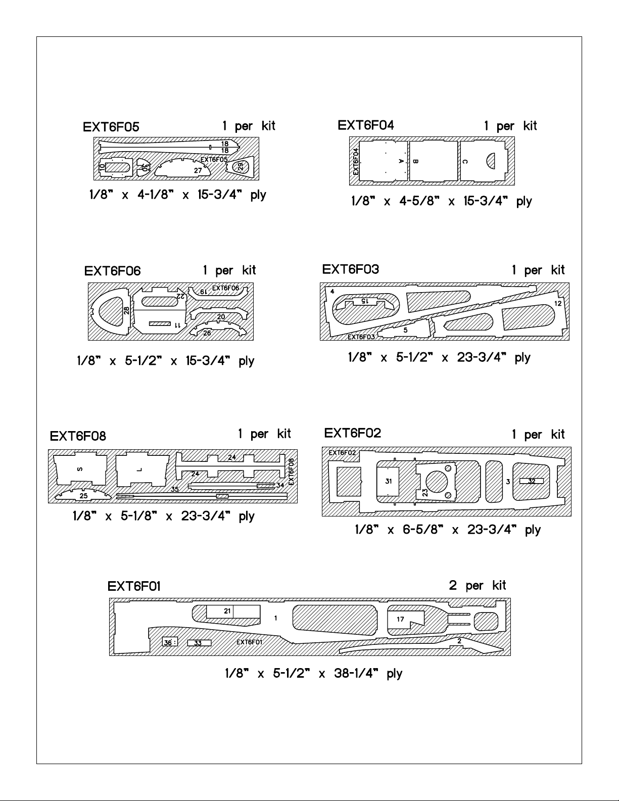
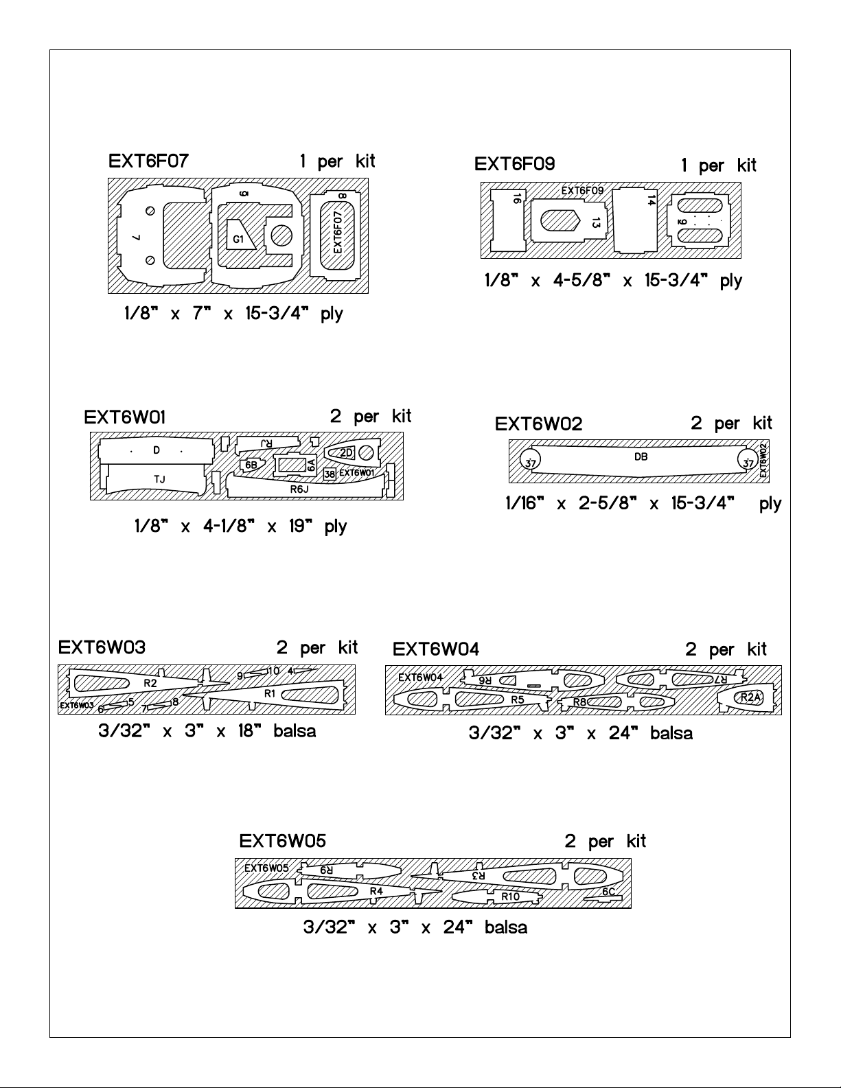
Die-Cut Patterns..........................................................................6 & 7
Build the Tail Surfaces ............................................................................8
Make the Stab Leading Edge Doubler...............................................8
Make the Stab & Fin Sheeting ...........................................................8
Build the Stab ....................................................................................9
Elevator Building Sequence.............................................................10
Fin Building Sequence.....................................................................10
Rudder Building Sequence ..............................................................11
Hinge the Tail Surfaces ....................................................................11
Finish the Tail Surfaces....................................................................11
Build the Wing........................................................................................12
Build the Wing Spars .......................................................................12
Build the Wing Panels......................................................................12
Sheet the Center Section.................................................................14
Servo Mount ....................................................................................14
Join the Wing Panels .......................................................................16
Sheet the Top of the Wing ...............................................................18
Build the Ailerons.............................................................................20
Build the Fuselage .................................................................................22
Assemble the Fuselage Formers & Sides .......................................22
Assemble the Fuselage ...................................................................23
Mount the Wing to the Fuselage......................................................24
Finish the Bottom of the Fuselage ...................................................27
Build the Front Fuselage Deck ........................................................29
Mount the Stabilizer to the Fuselage ...............................................30
Mount the Fin...................................................................................31
Build the Turtle Deck........................................................................31
Mount the Engine & Tank Tray.........................................................32
Install the Servos & Make the Pushrods..........................................33
Assemble the Wheel Pants..............................................................36
Assemble the Cowl ..........................................................................38
Balance the Model Laterally..................................................................39
Prepare the Model for Covering ...........................................................39
Cover the Model with MonoKote Film..................................................40
Covering Technique .........................................................................40
Suggested Covering Sequence .......................................................40
Painting...................................................................................................40
Final Hookups & Checks.......................................................................41
Join the Control Surfaces ................................................................41
Install the Hardware.........................................................................41
Attach the Canopy ...........................................................................42
Set the Control Throws ....................................................................42
Balance Your Model...............................................................................43
Preflight ..................................................................................................43
Charge the Batteries........................................................................43
Balance the Propeller ......................................................................44
Find a Safe Place to Fly ..................................................................44
Ground Check the Model.................................................................44
Range Check Your Radio ................................................................44
Engine Safety Precautions ..............................................................44
AMA Safety Code (excerpt)...................................................................45
General ............................................................................................45
Radio Control...................................................................................45
Flying ......................................................................................................45
Takeoff .............................................................................................45
Flying ...............................................................................................46
Landing ............................................................................................46
2-View Drawing ......................................................................................47
Flight Log................................................................................................48
Fuse & Wing Plans w/Parts List .......................Center Pull-Out Section
Your Extra 300S is not a toy, but a sophisticated, working
model that functions very much like a full-size airplane.
Because of its realistic performance, the Extra, if not
assembled and operated correctly, could possibly cause
injury to yourself or spectators and damage property.
If this is your first sport model, we recommend that you
get help from an experienced, knowledgeable modeler
with your first flights. You’ll learn faster and avoid risking
your model before you’re ready to take the controls for
yourself.
You may also contact the national Academy of Model
Aeronautics (AMA), which has more than 2,500 chartered
clubs across the country. Contact AMA at the address or
toll-free phone number below:
Academy of Model Aeronautics
5151 East Memorial Drive
Muncie, IN 47302-9252
Tele. (800) 435-9262
Fax (765) 741-0057
Or via the internet at: http://www.modelaircraft.org
Congratulations and thank you for purchasing the Great
Planes Extra 300S. We’ve selected the “S” because we feel
it looks the best and it is truly meant to perform aerobatics.
Among a few versions of the Extra 300 out there, another
popular one is the “L” which accommodates two
passengers–one student and one flight instructor.
The Extra is a rather “square shaped” airplane with well
defined lines. Coincidentally, this makes it exceptionally
easy to build and cover–especially for a semi-scale sport
model. Framing the model is very straightforward as most
of the structure features interlocking balsa and lite-ply. The
turtle deck sheeting may look a little intimidating but in
actuality it is quite easy to apply if you follow the
instructions and use the template provided to cut the
sheeting.
Flying the Extra 300S is a thrilling experience–as it should
be for such an aerobatic model! It doesn’t take much
elevator or aileron throw to put the Extra through its paces.
When you have a feel for your Extra 300S, the throws can
be increased to high rates (illustrated in the instructions) to
really showcase the aerobatic potential. The Extra performs
surprisingly well on a ball bearinged, Schnuerle ported .61,
INTRODUCTION
PROTECT YOUR MODEL,YOURSELF
& OTHERS...FOLLOW THIS
IMPORTANT SAFETY PRECAUTION
TABLE OF CONTENTS
2
Page 3
and even better with a .91 4-stroke, but seasoned experts
will surely want to get the most out of the Extra by
strapping on a .91 2-stroke or a 1.20 4-stroke.
We hope you enjoy building and flying your Great Planes
Extra 300S as much as we did flying the prototypes.
1. Build the model according to the plans and
instructions. Do
not alter or modify the model, as doing so may result in an
unsafe or unflyable model. In a few cases the plans and
instructions may differ slightly from the photos. In those
instances the plans and written instructions should be
considered as correct.
2. Take time to build straight, true and strong.
3. Use an R/C radio system that is in first-class condition,
and a correctly-sized engine and components (fuel tank,
wheels, etc.), throughout your building process.
4. Properly install all components so that the model
operates properly on the ground and in the air.
5. Check the operation of the model before every flight to
insure that all equipment is operating correctly and that the
model has remained structurally sound. Be sure to check
nylon clevises or other connectors often and replace them
if they show signs of wear or fatigue.
6. If you are not already an experienced R/C pilot, you must
fly the model only with the help of a competent, well
experienced R/C pilot.
Remember: Take your time and follow directions to end
up with a well-built model that is straight and true.
Please inspect all parts carefully before starting to build!
If any parts are missing, broken or defective, or if you
have any questions about building or flying this model,
please call us at (217) 398-8970 and we’ll be glad to help.
If you are calling for replacement parts, please reference
the part numbers and the kit identification number
(stamped on the end of the carton) and have them ready
when calling.
We can also be reached by E-Mail at:
productsupport@greatplanes.com
Items in parentheses (GPMQ4243) are suggested part
numbers recognized by distributors and hobby shops and
are listed for your ordering convenience. GPM is the Great
Planes brand, TOP is the Top Flite®brand, and HCA is the
Hobbico®brand.
❏ Four-channel radio with five servos (Optional 6th
servo for twin elevator servos)
❏ Engine – See Engine Selection above
❏ Exhaust – See Exhaust System above
❏ Spare glow plugs (O.S. #8 for most 2-stroke engines,
OSMG2691, O.S. Type-F for most 4-stroke engines,
OSMG2692)
❏ Propeller (Top Flite
®
Power Point™); Refer to your
engine’s instructions for proper size
❏ Top Flite Super MonoKote
®
covering (2 to 3 rolls) –
See Covering (page 40)
❏ Fuelproof paint, See Painting (page 40)
❏ Fuel tank 12 oz. (GPMQ4105)
❏ 3" Medium fuel tubing (GPMQ4131)
❏ 1/4" Latex foam rubber padding (HCAQ1000)
❏ 1/16" Foam wing seating tape (GPMQ4422)
❏ (2) 2-3/4" Wheels (GPMQ4224)
❏ (1) 3/16" Wheel collar (GPMQ4308)
❏ 2-1/2" Spinner (GPMQ4520, White)
❏ Pilot (DGA
®
1/4 scale sportsman pilot used in protype,
DGAQ2010)
❏ Fueling system (Great Planes Easy Fueler
™
,
GPMQ4160)
❏ Pacer Formula 560 canopy glue (PAAR3300)
Required Accessories
PREPARATIONS
Engine Selection
There are several engines that will work well in your
Extra 300S, but for unlimited performance we
recommend a hot 2-stroke such as an O.S.®.91FX or
SuperTigre™G90. If you prefer a 4-stroke, an O.S. .91
Surpass™works well and the O.S. 1.20 Surpass makes
unlimited vertical lines a part of every flight experience.
Your choice of 2-stroke or 4-stroke will determine the
location of the pushrod exit on the firewall, so plan ahead.
Exhaust System
If you choose to use a 2-stroke engine, you will need an
in-cowl muffler for the best appearance. On our protype
Extra 300S with the O.S. .61FX, we used the Slimline
#3217 Pitts Muffler (SLIG2217). With the O.S. Surpass
.91 and Surpass 1.20, we used the stock muffler
included with the engines. The Hobbico exhaust
extension allows the stock muffler to fit inside the cowl.
DECISIONS YOU MUST MAKE
NOTE: We, as the kit manufacturer, provide you with a
top quality kit and great instructions, but ultimately the
quality of your finished model depends on how you
build it; therefore, we cannot in any way guarantee the
performance of your completed model, and no
representations are expressed or implied as to the
performance or safety of your completed model.
PRECAUTIONS
3
Page 4
These are the building tools, glue, etc., that we recommend
and mention in the manual.
We recommend Great Planes Pro™CA and Epoxy.
❏ 2 oz. Pro CA (Thin, GPMR6003)
❏ 2 oz. Pro CA+ (Medium, GPMR6009)
❏ 1 oz. Pro CA+ (Thick, GPMR6014)
❏ 6-Minute Pro Epoxy (GPMR6045)
❏ 30-Minute Pro Epoxy (GPMR6047)
❏ CA accelerator (GPMR6035)
❏ Hand or electric drill
❏ Hobby knife handle (HCAR0105, #11 Blades
HCAR0311)
❏ Razor Saw
❏ Pliers (Common and Needle Nose)
❏ Screwdrivers (Phillips and flat blade)
❏ Small T-pins (HCAR5100)
❏ Medium T-pins (HCAR5150)
❏ Masking tape (TOPR8018)
❏ Bar sander or sanding block and sandpaper (coarse,
medium, fine grit)
❏ Easy-Touch
™
(or similar)
❏ Plan Protector (GPMR6167) or waxed paper
❏ Lightweight balsa filler such as Hobbico
®
HobbyLite
™
(Hobbico HCAR3401)
❏ Monofilament string for aligning wing & stabilizer
❏ 90º Building square (HCAR0480)
❏ Builders triangle set (HCAR0480)
❏ 1/4-20 Tap (GPMR8105, drill bit included)
❏ Electric power drill
❏ Sealing iron (TOPR2100)
❏ Heat gun (TOPR2000)
❏ Drill bits: 1/16", 5/64", 3/32", 7/64", 1/8", 5/32", #18 or
11/64", 3/16", #10 or 13/64", 7/32", 1/4", 17/64"
On our workbench, we have three 11" Great Planes
Easy-Touch Bar Sanders, equipped with 80, 150 and
220-grit sandpaper. This setup is all that is required
for almost any sanding task. We also keep some
320-grit wet-or-dry sandpaper handy for finish sanding
before covering.
Great Planes Easy-Touch Bar Sanders are made from
lightweight extruded aluminum and can be found at most
hobby shops. They are available in five sizes – 5-1/2"
(GPMR6169) for those tight, hard-to-reach spots;
11" (GPMR6170) for most general purpose sanding; and
22" (GPMR6172), 33" (GPMR6174) and 44" (GPMR6176)
for long surfaces such as wing leading edges. The
Easy-Touch Adhesive-Backed Sandpaper comes in
2" x 12' rolls of 80-grit (GPMR6180), 150-grit (GPMR6183),
180-grit (GPMR6184) and 220-grit (GPMR6185) and an
assortment of 5-1/2" long strips (GPMR6189) for the short
bar sander. The adhesive-backed sandpaper is easy to
apply and remove from your sanding bar when it’s time
for replacement.
Custom sanding blocks can be made from balsa or
hardwood blocks and sticks for sanding difficult or hard to
reach spots.
❏ CA Applicator tips (HCAR3780)
❏ Epoxy brushes (GPMR8060)
❏ Epoxy mixing sticks (GPMR8055, Qty. 50)
❏ CA Debonder (GPMR6039)
❏ Trim seal tool (TOPR2200)
❏ Hot Sock
™
(TOPR2175)
❏ Razor plane (MASR1510)
❏ Single-edge razor blades (HCAR0312)
❏ Straightedge (Hobbico Non-Slip, HCAR0475)
❏ Denatured or isopropyl alcohol (for epoxy clean-up)
❏ Dremel
®
Moto-Tool®or similar
❏ Cut-off wheel w/mandrel (GPMR8200)
❏ Curved tip canopy scissors (HCAR0667)
Elev = Elevator Fuse = Fuselage
LE = Leading Edge (front) LG = Landing Gear
Ply = Plywood Stab = Stabilizer
TE = Trailing Edge (rear) " = Inches
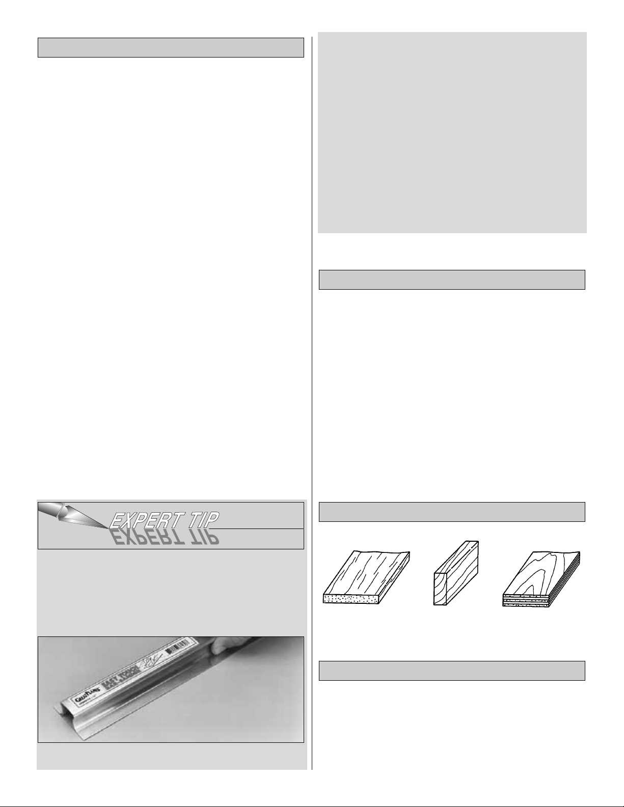
Bass = Basswood Fin = Vertical Fin
Common Abbreviations
Balsa Basswood Plywood
Types of Wood
Optional Tools or Accessories
Building Supplies and Tools
4
Page 5
5
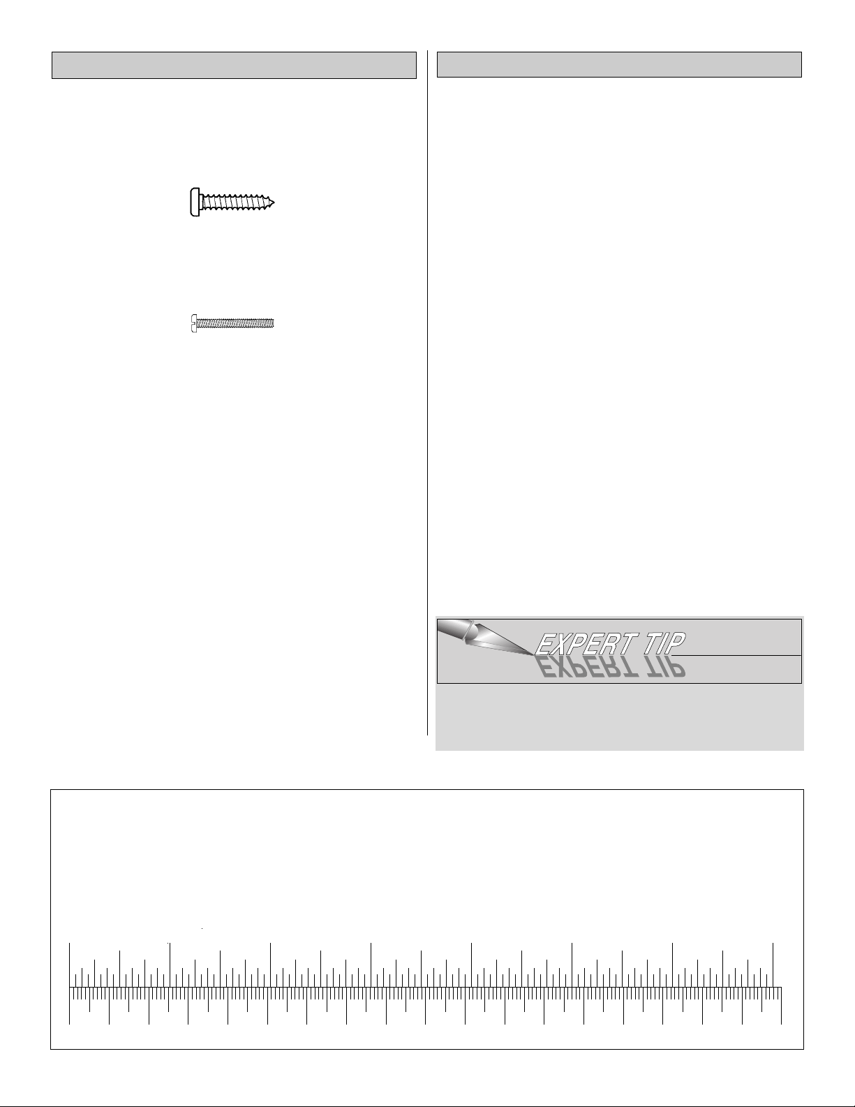
There are two types of screws used in this kit:
Sheet metal screws are designated by a number and a
length. For example #6 x 3/4"
Machine screws are designated by a number, threads per
inch and a length. For example 4-40 x 3/4"
When you see the term “test fit” in the instructions, it
means you should first position the part on the assembly
without using any glue and then slightly modify or sand
the part as necessary for the best fit.
Whenever the instructions tell you to glue pieces together,
CA or epoxy may be used. When a specific type of glue is
required, the instructions will state the type of glue that is
highly recommended. When 30-minute epoxy is
specified, it is highly recommended that you use only 30minute epoxy because you will need the working time
and/or the additional strength.
Several times during construction we refer to the “top” or
“bottom” of the model or a part of the model. For example,
during wing construction we tell you to “glue the top main
spar” or during fuse construction “trim the bottom of the
former.” It is understood that the “top” or “bottom” of the
model is as it would be when the airplane is right side up
and will be referred to as the “top” even if the model is
being worked on upside-down (i.e. the “top” main spar is
always the “top” main spar, even when the wing is being
built upside-down).
❏ 1. Unroll the plan sheet. Reroll the plan sheet inside out
to make it lie flat. Place wax paper or a Great Planes Plan
Protector™over the area of plan you are working on to
prevent glue from sticking to the plan. Use tape or tacks to
hold the plan and protector securely in place.
❏ 2. Remove all parts from the box. As you do, determine
the name of each part by comparing it with the plan and
the parts list included with this kit. Using a felt-tip or
ballpoint pen, lightly write the part name or size on each
piece to avoid confusion later. Use the die-cut patterns
shown on pages 6 and 7 to identify the die-cut parts and
mark them before removing them from the sheet. Save all
leftovers. If any of the die-cut parts are difficult to remove,
do not force them! Instead, cut around the parts with a
hobby knife. After punching out the die-cut parts, use your
Easy-Touch Bar Sander or sanding block to lightly sand
the edges to remove any die-cutting irregularities or slivers.
❏ 3. As you identify and mark the parts, separate them
into groups, such as fuse (fuselage), wing, fin, stab
(stabilizer) and hardware.
Zipper-top food storage bags are handy to store small
parts
as you sort, identify and separate them into
sub-
assemblies.
Get Ready to Build
Building Notes
0" 1" 2" 3" 4" 5" 6" 7"
0 10 20 30 40 50 60 70 80 90 100 110 120 130 140 150 160 170 180
Inch Scale
Metric Conversions
1/64" = .4 mm
1/32" = .8 mm
1/16" = 1.6 mm
3/32" = 2.4 mm
1/8" = 3.2 mm
5/32" = 4.0 mm
3/16" = 4.8 mm
1/4" = 6.4 mm
3/8" = 9.5 mm
1/2" = 12.7 mm
5/8" = 15.9 mm
3/4" = 19.0 mm
1" = 25.4 mm
2" = 50.8 mm
3" = 76.2 mm
6" = 152.4 mm
12" = 304.8 mm
18" = 457.2 mm
21" = 533.4 mm
24" = 609.6 mm
30" = 762.0 mm
36" = 914.4 mm
Page 6
6
DIE-CUT PATTERNS
Page 7
7
DIE-CUT PATTERNS
Page 8
You may remove the stabilizer and elevator drawing from
the wing plan by cutting along the dashed line. Don’t forget
to cover the plan with a Great Planes Plan Protector so the
glue won’t stick to the plan.
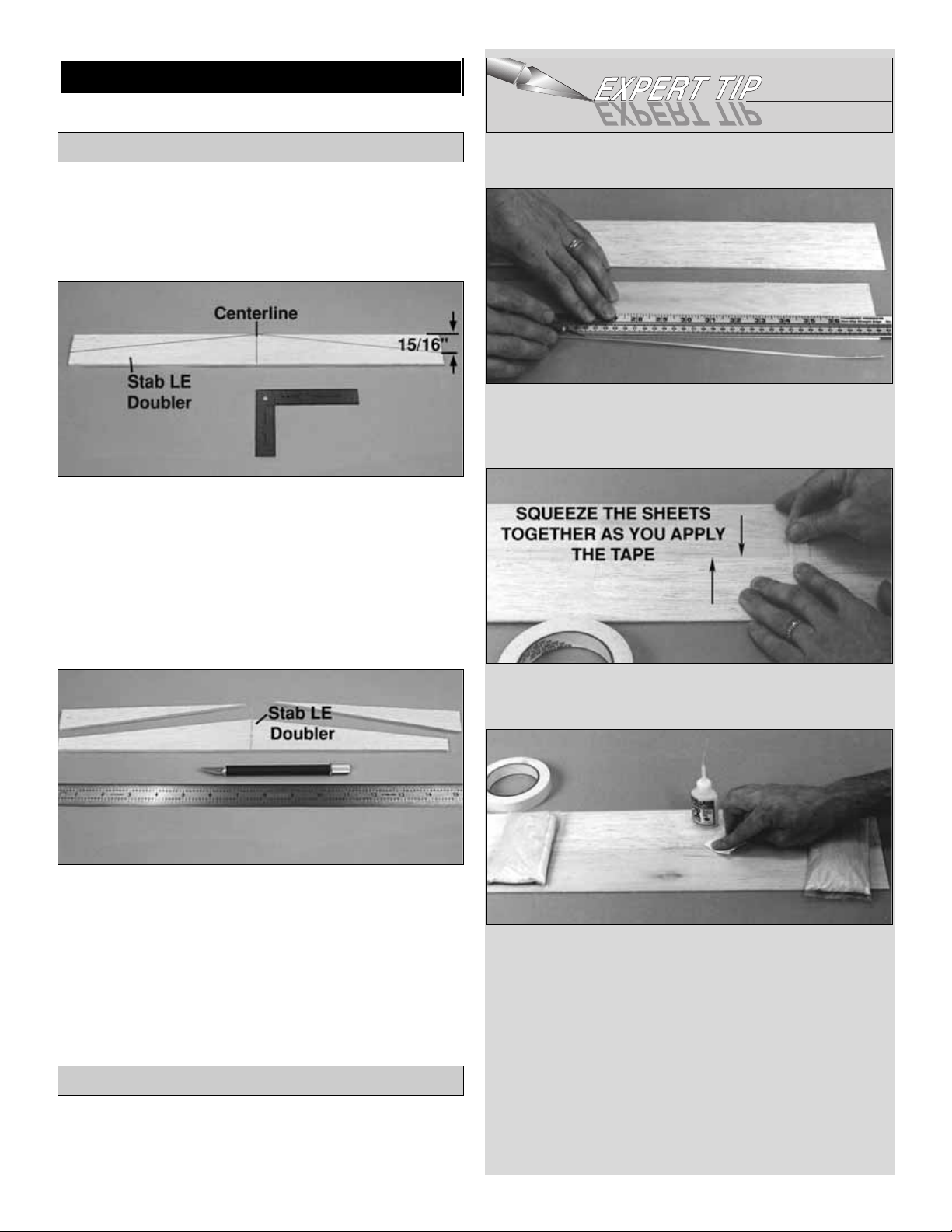
❏ 1. From the 3/16" x 1-1/2" x 24" balsa sheet cut down to
15". Use a ballpoint pen and a draftsmen’s square to
accurately mark the centerline of the 15" balsa sheet stab
LE doubler. Use your pen to make a mark on each end of
the doubler 15/16" from the LE.
❏ 2. Use a straightedge to draw lines connecting the
centerline of the stab LE doubler with the marks on the
ends as shown in the photo.
❏3. Use a hobby knife with a sharp #11 blade to cut along
the lines you drew. If necessary, use a bar sander to true
the leading edges you just cut.
❏ 4. Use the plan as a guide to mark and cut the bevel on
both ends of the stab LE doubler.
❏ 1. See the Expert Tip that follows, then glue three 1/16"
x
3" x 30" balsa sheets together. This will be cut in half
lengthwise creating the sheeting for the stab.
HOW TO JOIN SHEETING
A. Use a metal straightedge as a guide to trim one edge
of both sheets.
B. Use masking tape to tightly tape the two sheets
together joining the trimmed edges.
C. Turn the sheet over and place weights on top of the
sheet to hold it. Apply thin CA sparingly to the seam
between the two places, quickly wiping away excess CA
with a paper towel as you proceed.
D. Turn the sheet over and remove the masking tape,
then apply thin CA to the seam the same way you did for
the other side.
E. Sand the sheet flat and smooth with your bar sander
and 150-grit sandpaper.
Make the Stab & Fin Sheeting
Make the Stab Leading Edge Doubler
BUILD THE TAIL SURFACES
8
Page 9
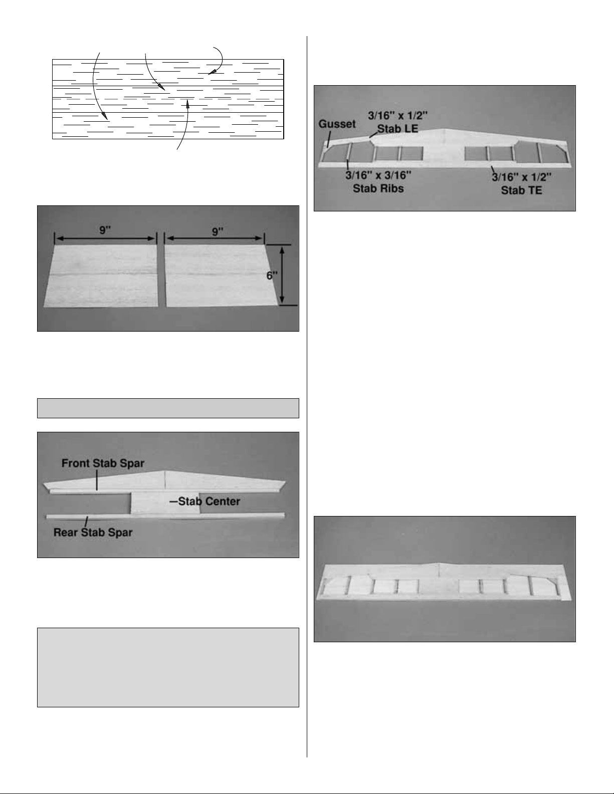
❏ 2. Cut the sheet you have made in half making two
sheets 4-1/2" x 30" stab sheets.
❏ 3. Cut the 1/16" x 3" x 36" balsa sheet into four 9"
sheets. Edge glue two of them together to make two sets of
1/16" x 6" x 9" fin sheets.
❏ 1. Pin the stab LE doubler in position over the plan. Fit
and glue a 3/16" x 3/16" x 14" basswood front stab spar,
to the back of the stab LE doubler. Wipe away excess CA
before it cures.
❏2. Test fit the 3/16" x 1-7/8" x 4" balsa stab center in
place.
You will need to trim the stab center down for a perfect fit.
When happy with the fit, glue it to the 3/16" stab spar.
❏ 3. Fit and glue the 3/16" x 3/16" x 14" basswood rear
stab spar to the rear of the stab center.
❏4. Glue the 3/16" x 1/2" x 30" balsa stab TE in place.
❏ 5. Using two 3/16" x 1/2" x 14" balsa sticks, fit and glue
the LE on the stab. Save the ends of the LE sticks for the
gussets at the outer LE corners.
❏6. From a 3/16" x 3/16" x 36" balsa stick, fit and glue the
eight stab ribs in place.
❏7. Using the leftover pieces you saved from the LE stick,
fit and glue two tip gussets in place.
❏ 8. Use your bar sander or a large sanding block and
220-grit sandpaper to sand the entire top and bottom
surface of the stab framework until it is flat and even. Be
careful while sanding so you do not over-thin any one
particular area of the stab or gouge the stab cross braces
by snagging the sandpaper on them.
❏❏9. Using medium CA, Glue the stab framework to one
of the stab sheets you made earlier, aligning the sheeting
parallel to the TE of the stab. Give the CA ample time to
cure before lifting the assembly off the work bench.
Note: It is essential to get a very secure and uniform bond
between the stab sheets and the stab core, especially in
the center.
Note: Refrain from using excessive accelerator. Even
hours after it’s sprayed on, residual accelerator can
prematurely and unexpectedly cure the CA you use later
on nearby glue joints. Unless you must handle or remove
the part from your building board right away we
recommend using no accelerator at all.
Build the Stab
1/16" x 3" x 30" balsa sheets
9
Cut down the middle to make two 4-1/2" sheets.
Page 10
❏❏10. Place the sheeted side of the stab on your work
bench and trim the sheeting around the outer edges of the
framework.
❏11. Repeat steps 9 and 10 to sheet the remaining side of
the stab.
❏❏1. Make the LE using a 5/16" x 1/2" x 14" balsa stick
(leave 1/16" of length at both ends).
❏❏2. Make the root end, cut from a 5/16" x 1" x 12"
balsa stick.
❏❏3. Make the TE using a 5/16" x 5/16" x 36" balsa stick
(leave 1/16" of length at both ends).
❏❏4. Make the tip and ribs using a 5/16" x 5/16" x 36"
stick.
❏❏5. Make the diagonal ribs using a 1/8" x 5/16" x 36"
balsa stick.
❏❏6. Remove the elevator from the plan and inspect all
glue joints. Add CA where necessary. Sand the LE and TE
flush with ends.
❏❏7. Add 1/8" balsa to both ends of the elevator. Sand
flat and smooth with a bar sander and 220-grit sandpaper.
❏8. Build the second elevator the same as the first.
Note: Because it is not necessary to build on the fuse
plans we reduced them to 75% so that they are easier to
use as a reference while building the fuse. Make sure to
build the fin and rudder over the full-size drawing, not
the reduced plan.
❏1. Make the LE and TE using 3/16" x 1/2" x 14" balsa
sticks.
❏ 2. Make the fin tip using the 3/16" x 1/2" balsa stick
remaining from step A.
❏ 3. Make the fin base using the leftover 3/16" x 1-1/2"
x 9" stick remaining from the stab LE doubler assembly.
❏ 4. Make the 3/16" fin ribs and cross trusses using the
leftover 3/16" x 3/16" stick from the stab rib assembly.
❏ 5. From 3/16" x 3/16" balsa fit and glue the bottom key
in place.
❏ 6. Remove the fin from your building board and inspect
all the glue joints. Add CA where necessary. Use your bar
sander to sand the top of the leading and trailing edges
even with the tip of the fin. Sand the bottom of the leading
edge even with the base. Sand the entire fin flat and
smooth with your bar sander and 220-grit sandpaper.
❏ 7. Sheet both sides of the fin with the 1/16" fin sheets
you made earlier using the same technique you did with
the stab.
❏8. From leftover 1/16" sheeting, sheet the fin post.
❏9. Trim and sand the sheeting flush with the framework.
Fin Building Sequence
Elevator Building Sequence
10
Page 11
❏ 1. Make the LE using a 5/16" x 1/2" x 14" balsa stick
(leave 1/16" of length at both ends).
❏ 2. Make the balance tab using 5/16" x 1-1/2" x 2-3/4"
balsa sheet.
❏ 3. Make the rudder bottom from the remaining piece of
5/16" x 1" stick leftover from the elevator root assembly.
❏ 4. Make the TE from the 5/16" x 5/16" stick leftover from
the elevator TE assembly.
❏
5. Make three rudder ribs using the remainder of the 5/16"
x 5/16" x 36" balsa stick.
❏ 6. Make the cross trusses and rudder top cap from the
remaining piece of 1/8" x 5/16" remaining from the elevator
assembly.
❏ 7. Using a leftover piece from the LE, glue the corner
gusset in place.
❏ 8. Inspect all the glue joints and add CA where
necessary. Shape the bottom of the rudder as shown on
the plan. Sand the entire rudder flat and smooth with your
bar sander.
❏❏1. Place the stab over its location on the plan and
lightly
mark the hinge locations on the trailing edge with a
ballpoint pen. Mark the hinge locations on the elevators
using the same procedure.
❏❏2. Cut the hinge slots in the elevator and stabilizer
using a #11 blade. Begin by carefully cutting a very shallow
slit at the hinge location to accurately establish the hinge
slot. Make three or four more cuts going a little deeper each
time. As you cut, slide the knife from side to side until the
slot has reached the proper depth and width for the hinge.
❏❏3. Cut twenty four 3/4" x 1" hinges for the elevators
and rudder from the supplied 2" x 9" hinge material, then
snip off the corners. Temporarily join the elevators to the
stab with the hinges, adjusting any hinge slots if necessary
so they all align. Do not glue the hinges in place until
you are instructed to do so.
❏ 4. Return to step 1 and use the same procedures to
hinge the rudder and fin.
❏ 1. Shape the leading edge of the elevators to a “V” as
shown on the plan using a razor plane and bar sander.
❏ 2. Use the same procedure to bevel the leading edge of
the rudder. It will be necessary to sand the bevel at the top
of the rudder hinge line using your sanding block, because
the balance tab will not allow the razor plane to go the
full length.
❏ 3. Use your bar sander and 150-grit sandpaper to round
the tail surfaces as shown on the fuse plan.
That’s about it for the tail surfaces. They’re a little more
work than sheet surfaces but they are much lighter, just as
strong, and a nice piece of craftsmanship. Clean off your
work bench and get ready for the wing!
Finish the Tail Surfaces
Hinge the Tail Surfaces
Rudder Building Sequence
11
1"
1"
3/4"
Page 12
Note: The following instructions explain how to build the
wing directly over the plans. We’ll start by building the left
wing panel upside-down over the left wing panel plan so
your progress matches the photos.
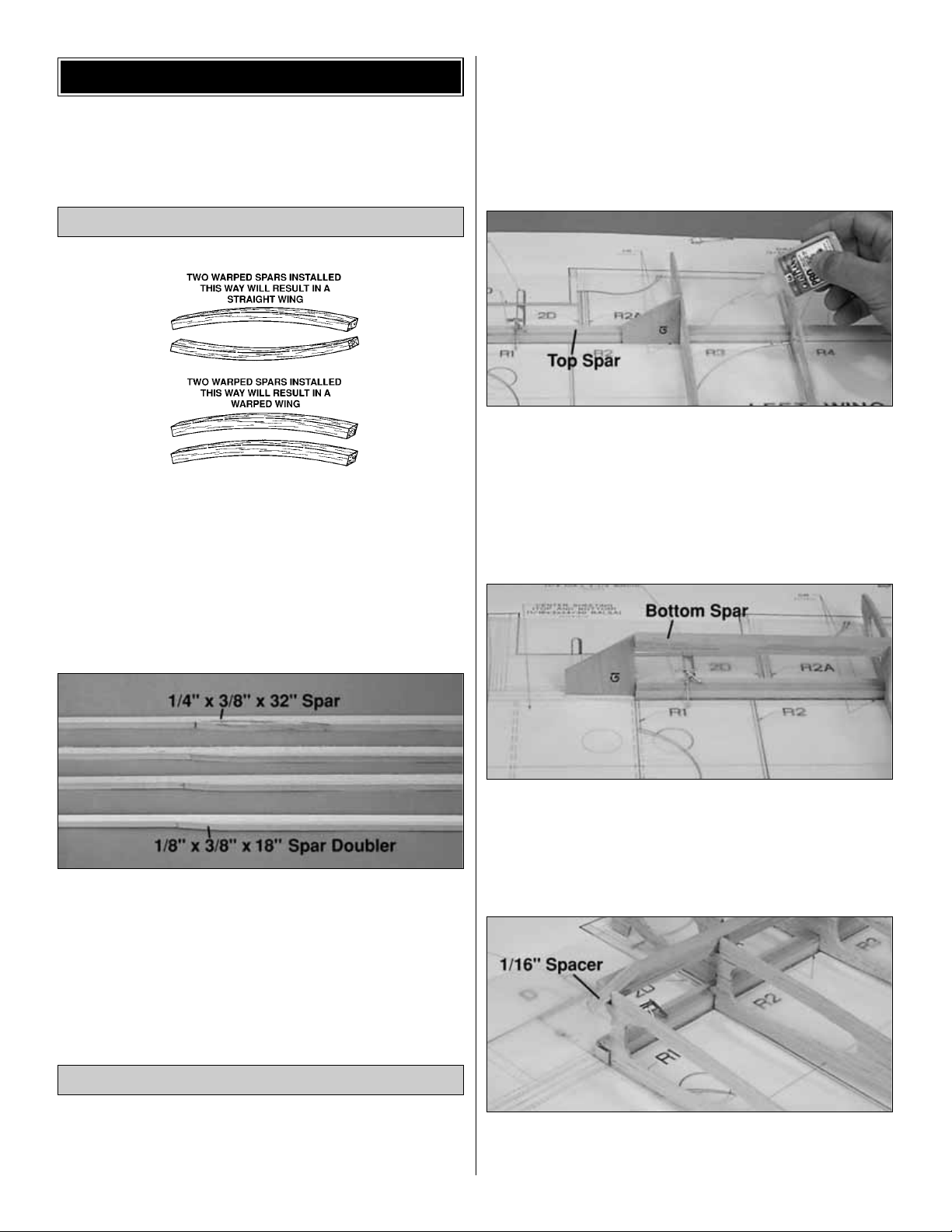
❏ 1. Before using the 1/4" x 3/8" x 32" basswood spars,
examine them carefully for possible imperfections. Look for
knots, soft spots, diagonal grain and any other
imperfections. If possible, position each spar so the
imperfections (if any) are on the outer half of the wing panel
(toward the tip), where they will be least affected by high
stresses. If the spars are warped slightly, try to “balance
them out” by installing the warped spars in opposite
directions (see sketch).
❏ 2. Find the 1/8" x 3/8" x 18" basswood sticks. Cut the
sticks down to 15-3/4" making the spar doublers. Sand
one end of each of the four spar doublers to a taper as
shown on the plan. Glue the spar doublers to the spars and
sand off any excess glue.
❏ 3. Carefully press out all the die-cut 3/32" balsa wing
ribs. Sand the edges slightly to remove any die-cutting
irregularities.
❏❏1. Tape the left wing plan to your flat work surface,
and cover the wing drawing with Great Planes Plan
Protectors (so you won’t glue the wing to the plan!).
❏❏2. Cross pin a top spar to the plan with the doubler
up and toward the root. Note: The spars are cut slightly too
long. Align them at the root and leave the excess past the
tip rib.
❏❏3. Glue ribs R3 to R10 to the top spar over their
locations shown on the plan, using rib gauge G1 to set the
ribs at the correct angle. Note: One angle on G1 is used as
a rib angle guide and the other angle on it is used for
setting the cockpit rear former at the correct angle.
❏❏4. Place the bottom spar into the rib notches, and use
G1 to position the root end of the spar. When satisfied with
the fit, glue the spar to the ribs with thin CA.
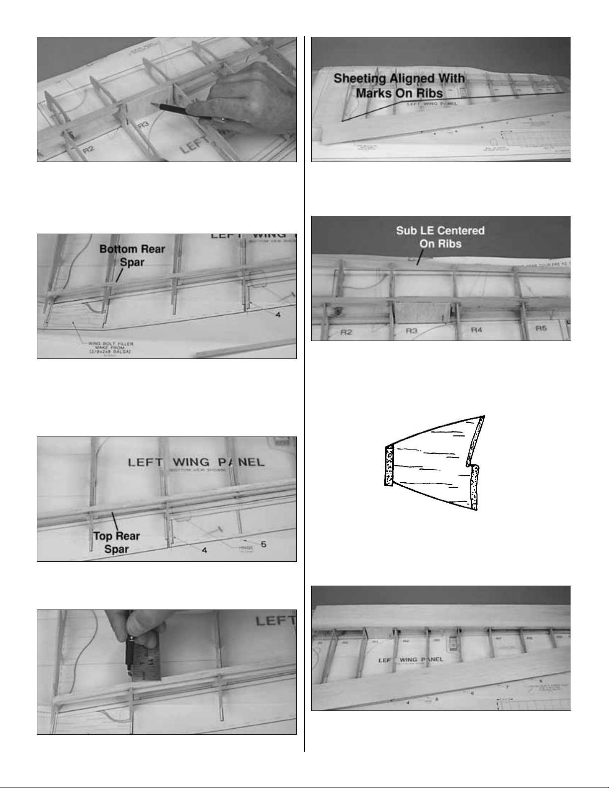
❏❏5. Glue R1, R2 and R2A in place using a leftover
piece of 1/16" ply as a spacer to locate the ribs 1/16" away
from the spars. Do not glue the spacer while gluing the ribs.
Build the Wing Panels
Build the Wing Spars
BUILD THE WING
12
Page 13
❏❏6. From a 3/32" x 3" x 24" balsa sheet, make shear
webs to fit from ribs R3 through R8, with an additional web
aft of the spars between R3 and R4. Hint: Use a #11 hobby
knife to hold the cut shear webs while putting glue on the
web and put the webs in place.
❏❏7. Glue the 1/8" x 1/4" x 36" balsa bottom rear spar
in place butting it against R1. Remember we are building
the wing upside-down so the bottom spar is on the top now.
Note: It is necessary to bevel the root end of the spar so it
will fit well against R1.
❏❏8. Pull the 1/8" x 1/4" x 36" balsa top rear spar up
into the notches in the ribs and glue in place. Trim the ends
of the rear spars off at the wing tip.
❏❏9. Make marks on the ribs 3/8" forward of the rear
spar.
❏❏10. Glue a piece of 1/16" x 3" x 36" balsa sheet on
the TE of the wing, aligning the LE of the sheeting with the
marks you made in step 9.
❏❏11. Glue the 3/32" x 5/8" x 30" sub LE on the LE of
the ribs, centering it vertically and leaving the excess at the
root of the wing.
❏❏12. Use a razor plane and/or a sanding block, shape
the sub LE so it aligns with the tops of the ribs and the
shape of the airfoil.
❏❏13. Glue a 1/16" x 4" x 32" balsa sheet to the forward
half of the main spar. Note: Make sure the sheeting hangs
over the tip rib and the center of the wing slightly.
13
Page 14
❏❏14. Carefully lift the sheeting away from the ribs, then
apply a bead of medium or thick CA to the top of each rib
and the sub LE. Working quickly, pull the sheeting forward
as you press it down to the ribs and the sub LE. Use
weights to hold the sheeting to the ribs and sub LE until the
CA cures. Note: It may be necessary to place weights on
the TE of the wing so that the TE of the wing stays down on
the jig tabs.
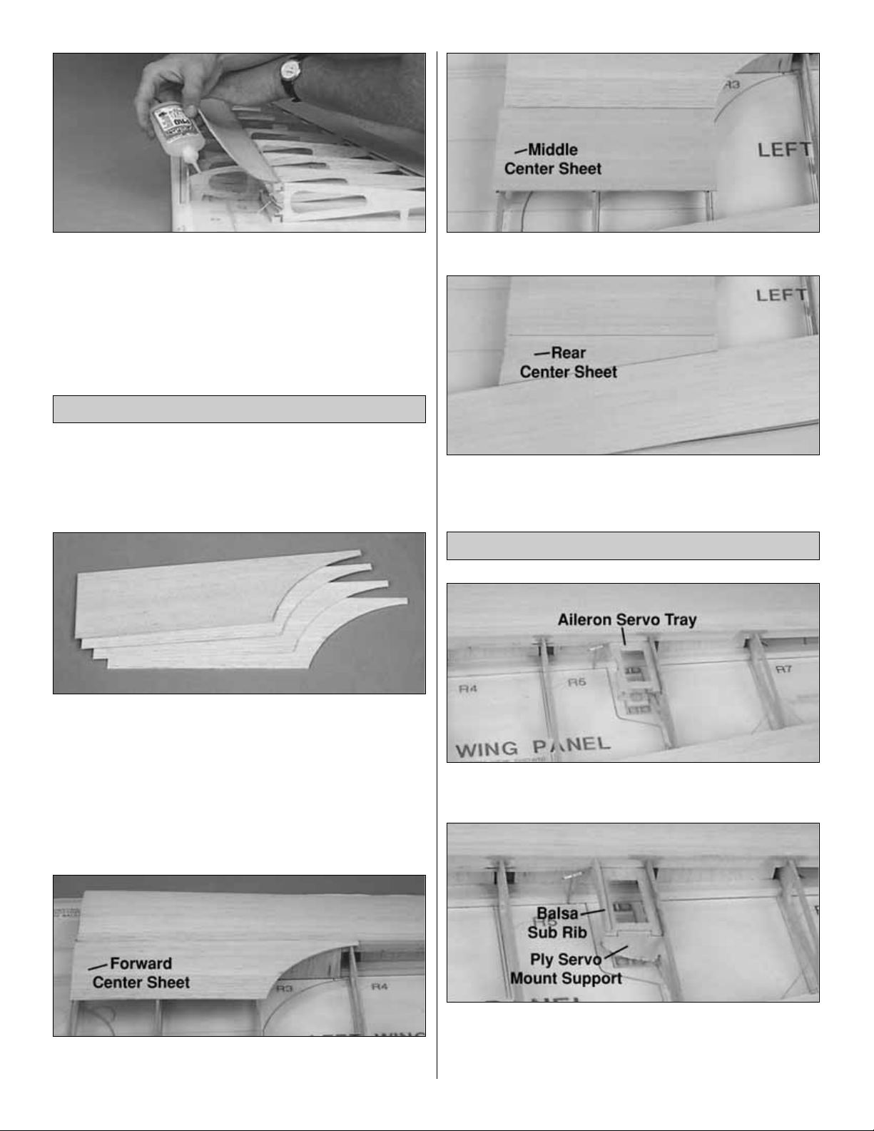
❏ 1. From a 1/16" x 3" x 36" balsa sheet, cut three 10-1/2"
long sheets. From another 1/16" x 3" x 36" sheet, cut one
more 10-1/2" long sheet. Save the remaining 25-1/2" for
step #3.
❏2. Cut a curve on the end of one of the sheets, using the
plan as a guide. The curve does not have to be an exact
match. Use that one as a template to mark and cut the
three other sheets. These are the forward center sheets.
❏ 3. From a leftover piece of 1/16" x 3" x 25-1/2" balsa
sheet, cut three 7" long sheets. From a 1/16" x 3" x 36"
balsa sheet, cut five 7" long sheets. These eight 7" pieces
are used for the rest of the center sheeting.
❏❏4. Fit and glue one of the four forward center sheets
(from step 2) in place on the wing.
❏❏5. Glue the 7" balsa middle center sheet in place.
❏❏6. Using a 7" balsa sheet, fit and glue the rear center
sheet in place.
❏❏1. Glue the die-cut 1/8" ply aileron servo tray (6A) to
the spar and rib with medium CA.
❏❏2. Glue the die-cut 1/8" ply servo mount support
(6B) in place.
❏❏3. Glue the die-cut 3/32" balsa sub rib (6C) in place.
Servo Mount
Sheet the Center Section
14
Page 15
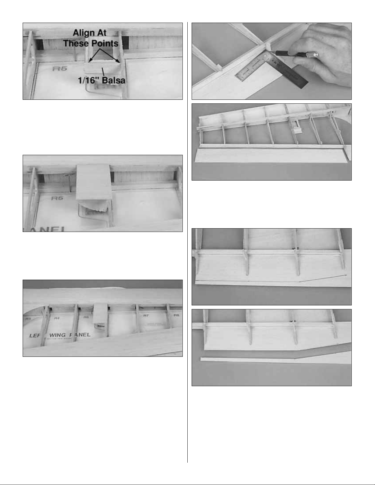
❏❏4. Glue a piece of 1/16" balsa to the servo mount
support, aligning it with the top of the sub rib and the top of
R6 as shown in the photo.
❏❏5. Using leftover 1/16" balsa, sheet over the servo
tray area. Note: You will cut the opening for the servo after
the wing is unpinned from your building board.
❏❏6. From a 1/16" x 1/4" x 36" balsa stick, cut and glue
cap strips to all of the exposed ribs. Hint: For easier
positioning of the cap strips, first mark the location of each
rib on the LE and TE sheeting.
❏❏7. Remove the T-pins, then take the wing off your
building board.
❏❏8. Trim the LE sheeting flush with the front of the
sub LE.
❏❏9. Cut the TE sheeting along the outside edge of R4
from the aft edge of the spar to the aft edge of the sheeting.
Trim the TE sheeting flush with the aft spar from R4 to the
wing tip. Note: Save this piece of sheeting for the aileron.
❏❏10. Draw a line 1/2" behind the TE of R2 - R4. Draw
another line 1/2" behind R1 and R2. Trim the TE sheeting
on the lines you just made.
❏❏11. Trim the center sheeting and TE sheeting flush
with R1.
❏❏12. Use a razor saw to accurately cut the spars, sub
LE, LE sheeting and TE sheeting flush with R10.
15
Page 16

❏❏13. From the 3/8" x 2" x 8" balsa block, fit and glue
the wing bolt filler between the TE of R1 and R2. Sand
the wing bolt filler to the contour of ribs R1 and R2.
❏❏14. Cut the opening for the servo in the sheeting
using
the servo tray as a guide.
❏❏15. Fit your aileron servo in place and trim the
sheeting
from around the rubber grommets on your servo. Note: You
need approximately 1/16" of clearance between the servo
and the sheeting.
❏❏16. Trim the jig tabs off the ribs and sand the ribs
smooth.
Be careful not to sand into the ribs, changing the shape of
the airfoil.
❏❏17. Use a razor plane and/or a sanding block to
shape
the sub LE so it aligns with the tops of the ribs and the
shape of the airfoil.
❏❏18. Using a razor saw and a hobby knife, trim the
spacer tabs off of R1, R2 and R2A.
❏❏19. Sand the bottom TE sheeting as shown in the
sketch.
If this is your first time through, go back to the start of Build
the Wing Panels on page 12 and build the right wing half.
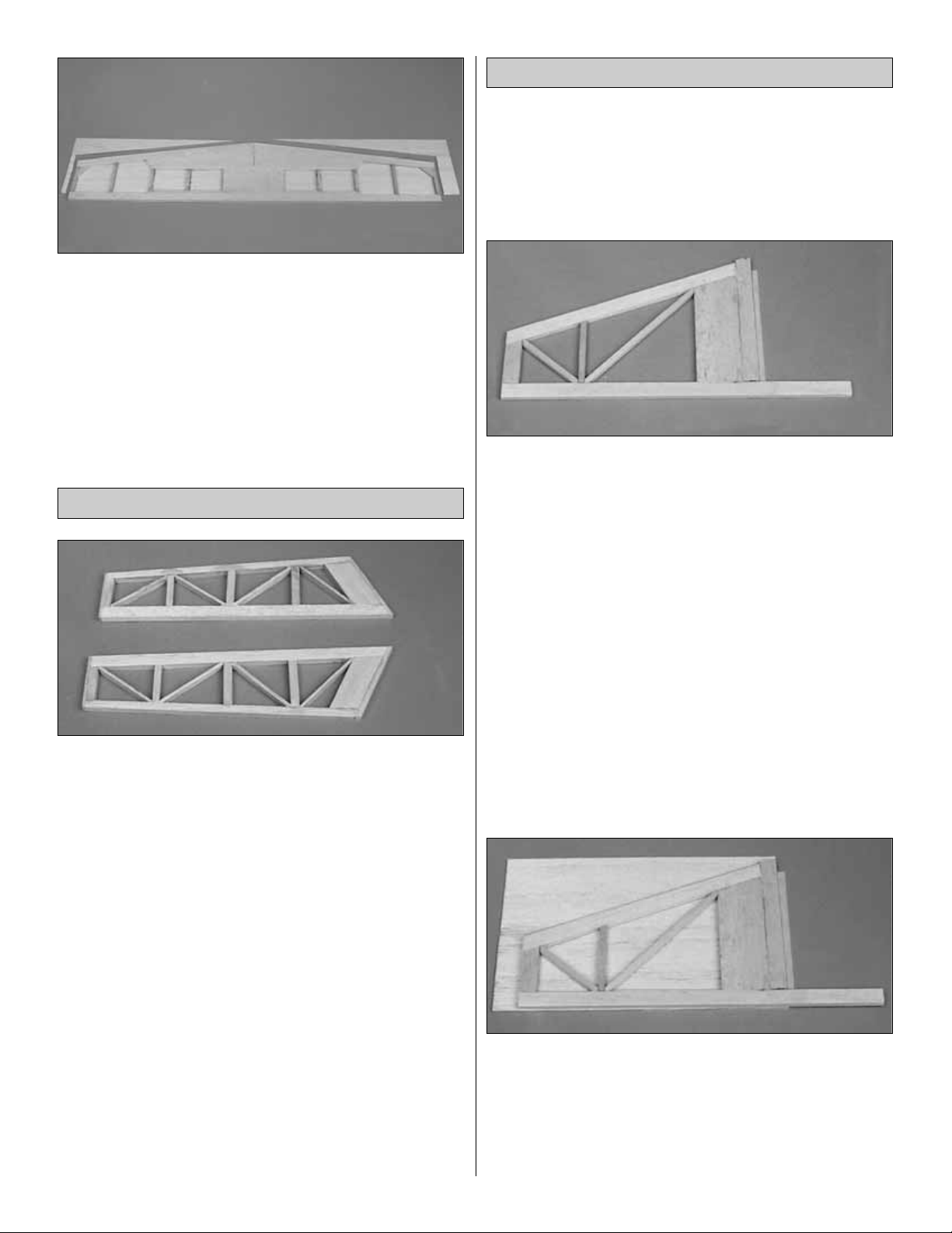
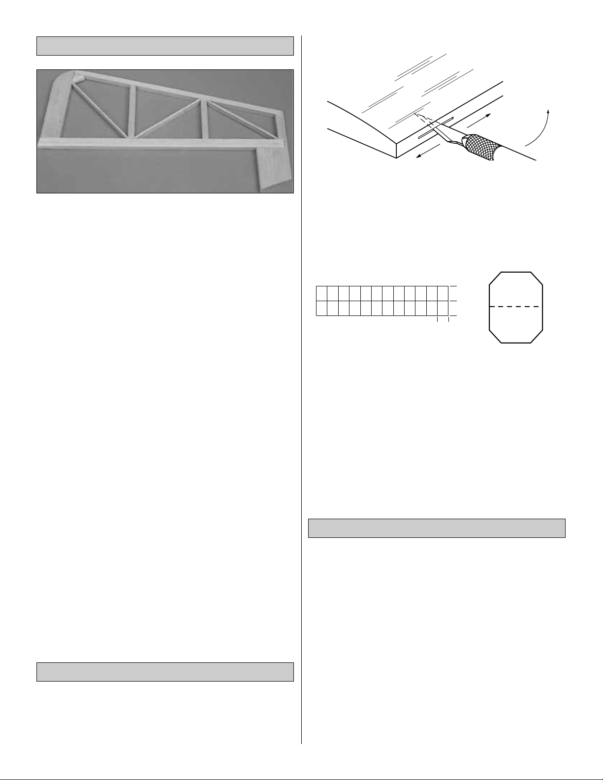
❏ 1. From the die-cut 1/8" ply pieces, make the five wing
jigs as shown in the photo above.
❏ 2. Without using any glue, test join the wing panels on
the five wing jigs as shown in the photos for steps 2 and 3.
Make sure the ends of the spars and TE’s join without
any gaps.
Join the Wing Panels
16
Page 17

❏ 3. Place a Great Planes Plan Protector under the center
of the wing to catch excess epoxy. When satisfied with the
fit, glue the die-cut 1/16" ply dihedral braces (DB) to the
spars with 30-minute epoxy by spreading a film of epoxy on
both the spars and the dihedral braces and using C-clamps
to hold them in place. Once the C-clamps are tightened,
wipe away excess epoxy before it cures. Place weights on
top of your wing to hold it in place.
❏ 4. Glue the TE’s together with thin CA. Do not disturb
the wing until the epoxy cures.
❏ 5. Drill two 1/4" holes in the each of the two die-cut 1/8"
ply dowel plates (D).
❏ 6. Glue the die-cut 1/8" ply sub ribs (2D) to one of the
dowel plates, using a square to assure alignment.
❏ 7. Glue the other dowel plate into the slots in the sub
ribs. Note: Make sure the “V’s” on the dowel plates are
both on the same side.
❏8. Measure and make an accurate reference mark at the
center point on the top of both dowel plates.
❏ 9. Use 6-minute Great Planes Pro Epoxy to glue the
dowel plate to the dihedral brace, aligning the center mark
you made with the spar joint, and clamp it in place. Note:
Do not allow epoxy to get in the dowel holes on the
dowel plate.
❏ 10. Glue the forward dowel plate and the sub ribs to the
wing sheeting with thin CA.
17
Page 18

❏ 11. Trim the sub LE and the sheeting flush with the sub
ribs and the dowel plate.
Note: While sheeting the top of the wing it is not necessary
to put the jigs under the whole wing. It is only necessary to
put the jigs under the wing half you are sheeting.
❏1. Put the wing back on the building jigs for the next 6
steps.
❏❏2. Make marks on the ribs 3/8" in front of the aft spar,
the same as you did on the bottom of the wing.
❏❏3. Align a 1/16" x 3" x 36" balsa TE sheet to the
marks you just made, and trim the end of the sheet to the
angle at the center of the wing.
❏❏4. Glue the TE sheet in place, aligning it with the
center of the wing and the marks you made in step 3. Note:
It is necessary to move the center jig over slightly so the
sheeting can align with the marks you made and extend
over the bottom TE sheeting.
❏❏5. Lift the wing off the building board and trim the
sheeting the same as you did on the bottom of the wing.
Save the bigger piece for the aileron.
❏6. Repeat steps 2-5 for the other wing half.
❏❏7. Put the wing back on the jigs again. Glue the 1/16"
x 4" x 32" balsa LE sheeting to the spar, aligning the TE of
the sheeting to the center of the spar.
❏❏8. Glue the sheeting to the ribs and sub LE as you
did on the bottom of the wing.
❏❏9. Trim the sheeting flush with R10, the sub LE, the
ply sub rib and the dowel plate.
❏ 10 Repeat steps 7-9 to add the LE sheeting to the other
wing half.
Sheet the Top of the Wing
18
Page 19

❏ 11. Sheet the center of the wing with the remaining six
pieces of center sheeting.
❏12. Use the two remaining 1/16" x 1/4" x 36" balsa sticks
to cap strip all the exposed ribs.
❏ 13. From the 3/16" x 1/4" x 30" balsa stick cut eight 3"
long hinge blocks.
❏ 14. Test fit one of the hinge blocks between the TE
spars and between R4 and R5. When satisfied with the fit
glue in place with thin CA.
❏ 15. Do the same between R6 and R7, between R7 and
R8, and between R9 and R10 on both wing halves.
❏16. Sand the TE of the wing square.
❏17. Glue the two 3/32" x 9/16" x 24" balsa TE caps in
place.
❏ 18. Cut the ends of the TE caps off flush with the sides
of the wing tip.
❏19. Sand the TE caps flush with the TE sheeting.
❏ 20. Glue the 5/16" x 5/8" x 30" LE in place. Sand the
root of the LE flush with the sub ribs. Sand the tips flush
with R10.
19
Shape the 3/16" x 1/4" x 3" stick so it will
fit between the rear spars.
Page 20

❏21. Sand the LE to the airfoil shape shown on the plans.
❏ 22. Using the plans as a reference, cut the servo wire
holes in the top of the wing.
❏ 23. Cut two 6-1/4" long pieces from the 1/4" x 2" x 24"
balsa sheet for the wing tip caps. Cut two more 2-1/4"
long pieces for the root rib caps.
❏ 24. Glue the 6-1/4" long tip caps to the wing tips. Glue
the 2-1/4" long root caps to the root ribs.
❏ 25. Sand the root caps and tip caps to match the shape
of the wing.
❏ 26. Slightly round one end of both of the 1/4" x 2-1/2"
wing dowels.
❏ 27. Test fit the dowels into the wing. When satisfied with
the fit, use 6-minute epoxy to glue the dowels in place.
❏1. Remove the fourteen die-cut 3/32" balsa aileron ribs,
labeling each of them as you do so. Cut 2" off the end of a
3/8" x 3/8" x 24" balsa stick to be used for the control horn
doubler in the aileron.
Build the Ailerons
20
Page 21

❏❏2. Find one of the 1/16" balsa sheets that you have
saved from the TE sheeting of the wing, and trim it to 2"
wide. Glue the 3/8" x 3/8" x 24" balsa aileron LE to the
sheet, aligning it along one of the trued edges of the sheet.
❏❏3. Cover the aileron portion of the plan with a Great
Planes Plan Protector. Pin the aileron sheet with Aileron LE
in place on the plan. Use thin CA to glue the seven die-cut
3/32" balsa aileron ribs perpendicular to the bottom sheet
and tight against the 3/8" aileron LE.
❏❏4. Glue the control horn doubler in position against
aileron rib #6.
❏❏5. Remove the aileron from the building board, trim
the sheeting flush with ribs #4 and #10.
❏❏6. Sand the aileron LE and the TE of the sheeting
with your sanding bar as shown in the sketch.
❏❏7. Using another 1/16" balsa sheet that you saved
from the TE sheeting, glue the bottom aileron sheeting in
place, aligning it with the TE of the top aileron sheet on the
sanded aileron.
❏❏8. Trim the bottom aileron sheeting flush all the way
around the aileron.
❏❏9. Glue a leftover piece of 1/16" balsa aileron cap, to
the root end of the aileron.
❏❏10. Cut 2-1/8" from the 1/4" x 2" x 7" balsa stick you
saved from the wing building section. Cut the 2-1/8" piece
in half lengthwise making two aileron caps. Glue the
aileron cap onto the aileron tip end, save the other piece for
the other aileron.
❏❏11. Sand the aileron caps flush.
❏❏12. Bevel and hinge the aileron the same as did with
the elevator and rudder. Cut the hinge slots in the wing TE
to match the hinge locations on the aileron.
❏13. Go back to step #2 and build the other aileron.
21
Page 22

❏ 1. Use 30-minute epoxy to glue the firewall formers A,
B and C together. Make sure the embossed label on A is
facing UP and the top edge and tabs on all three formers
are aligned. Wipe away excess epoxy before it cures. From
now on this assembly will be referred to as the firewall.
Note: If the formers are warped, simply clamping them
together may not “cancel out” the warps. It is best to clamp
the formers to a table or a flat board until the epoxy cures.
❏ 2. Lay the two fuselage sides (part #1) next to each
other as shown in the photo and label the insides as the
LEFT and RIGHT. It is important that you lay the fuselage
sides in a mirrored position to insure that you build a right
and a left side.
❏ 3. Fit former 7 (part #7) in place on the right fuse side.
Butt the fuse doubler (part #2) up against former 7 and
mark around the perimeter of the fuse doubler.
❏ 4. Use medium CA to accurately glue the fuse doubler
(part #2) to the inside of the right fuselage side. Do not
glue former 7 in place at this time.
❏ 5. Glue the left fuselage doubler to the inside of the left
fuselage side in the same manner.
❏ 6. Drill a 3/16" hole through each of the punch marks in
formers 9 and 10.
Hint: Place the formers on a leftover piece of wood and
press down as you drill the hole so the former does not split
when the drill goes through.
❏ 7. Draw center lines connecting the outer punch marks
on the firewall. Drill 7/32" holes for the engine mount bolts
at the four engine mount punch marks. Drill a 3/16" hole for
the throttle pushrod at the punch mark. Drill two 15/64"
holes for the fuel tubes.
❏ 8. Press four supplied 8-32 blind nuts into the holes on
the back of the firewall. Gently tap the blind nuts with a
hammer to fully seat them into the firewall, then add a few
drops of thin CA around the blind nuts to secure them.
❏ 9. File off the 1/64" of the blind nuts that extend above
the top of the firewall.
Assemble the Fuselage
Formers & Sides
BUILD THE FUSELAGE
22
Page 23

❏ 1. Draw a straight line on your work surface 45" long.
Cover this line with Great Planes Plan Protector.
❏ 2. Pin the die-cut 1/8" ply forward fuse top (part #3) in
position over your reference line, aligning the V-notches
with the line. Make sure the front of the fuse is the same as
shown in the photo.
❏3. Fit the die-cut 1/8" ply aft fuse top (part #12) in place
and align it with the reference line. When satisfied with the
alignment, glue it to the fuse front with thin CA.
❏ 4. Keeping the die-cut 1/8" ply former 6 (part #6)
perpendicular to the fuse top, glue it in place with thin CA.
❏5. Glue former 7 (part #7) in place the same way.
Note: These next three steps should be completed
together and assembled quickly.
❏ 6. Wet the outside of both fuse sides from the middle of
the wing saddle forward.
❏ 7. Glue the fuse sides to the fuse top from former 6 to
the middle of the wing saddle with thin CA and accelerator.
❏ 8 Hold the fuse sides in place with tape, clamps or your
hands and glue to the formers with medium CA or epoxy.
Hint: Using tape to hold the fuse sides in position makes it
possible to leave the tape in place on the fuse until the
landing gear former and bottom corner pieces are put
in place.
The fuse plans were reduced to 75% so that they are
easier to use as a reference while building. The
interlocking construction of this kit allows you to quickly
assemble the fuselage upside-down on a line drawn on
your work surface while being able to reference the plans
because they are not covered up with the parts you are
assembling. You will be fitting most of the die-cut fuselage
parts together before applying glue. Do not use any glue
until instructed to do so.
Assemble the Fuselage
23
Page 24

❏9. Glue the rest of the fuse sides to the fuse top.
❏10. Glue former 8 (part #8) in place.
❏ 11. Glue former 9 (part #9) and former 10 (part #10)
in place.
❏ 12. Glue the fuse bottom (part #4) in place. Note:
Former 9 extends through the fuse bottom. This will be used
as a guide for the bottom stringers later in the manual.
❏13. Glue former 11 (part #11) in place.
❏ 14. Sand the 1/4" x 1-1/4" x 5-1/2" birch ply wing bolt
block to fit precisely in the slots in the fuse doublers. Note:
It is very important that the fit of the wing bolt block
be precise.
❏ 15. When satisfied with the fit of the wing bolt block,
glue it in place with 30-minute epoxy.
❏ 1. Sand the entire wing saddle area lightly until the fuse
side doublers and fuse sides are flush.
❏ 2. Test fit the wing on the fuse. If the wing is slightly too
large (front to rear) to fit into the saddle, sand the TE of the
wing slightly until it fits.
❏ 3. Laminate two pairs of the die-cut 1/16" wing dowel
disks together with 6-minute epoxy. Drill 1/4" holes through
the punch marks at the center of each of the laminated
disks.
Mount the Wing to the Fuselage
24
Page 25

❏ 4. Center the wing side to side, leaving equal space
between the fuse sides and the wing at the leading edge.
❏ 5. Making sure to keep the wing centered and in the
saddle, tack glue the dowel disks (part #37) in place with
thin CA. Note: DO NOT GLUE THE DOWEL DISKS TO
THE WING DOWELS.
❏ 6. Remove the wing and permanently glue the dowel
disks in place with thin CA.
❏ 7. Stick a T-pin through the center of the aft end of the
fuselage bottom. Tie a string to the T-pin. Pull the string to
the TE of the wing tip and put a piece of masking tape on
the string at the wing tip. Mark an arrow on the tape, then
slide the tape on the string so the arrow aligns with the
wing tip. Swing the string over to the other tip and see if it
aligns with the same point. If necessary shift the wing and
mark the location of the tip by adjusting the position of the
tape on the string. Do this until the arrow on the string
aligns with both tips.
❏ 9. Make two alignment marks on the TE of the wing
where it meets the fuse. Note: You will build the belly pan
onto the wing before the wing gets mounted to the fuse, so
it is important the wing stay straight in the fuse for the next
steps until the wing is bolted to the fuse.
❏ 10. Cover the area of the belly pan with a Great Planes
Plan Protector or waxed paper. Pin the aft belly pan
former (part #22) to the fuse.
❏ 11. Fit the belly pan sides (part #18) and middle belly
pan former (part #20) in place, holding the front of the
belly pan sides at equal distances from the fuse sides.
When satisfied with the fit, glue the sides to both formers.
❏ 12. Glue the die-cut 1/8" ply forward belly pan former
(part #19) to the belly pan sides. The sides will need to be
bent inward to fit the former, be sure to keep the former
centered on the fuse sides.
25
Page 26

❏ 13. Remove the belly pan from the wing and glue the
die-cut 1/8" ply belly pan plate (part #23) in place, making
sure it fits all the way into the pockets. Sand the belly pan
plate flush with the aft belly pan former.
❏ 14. Double check the alignment of the wing in the fuse,
then glue the belly pan to the wing with thin CA. Note: Do
not glue the wing to the fuse.
❏ 15. Glue the die-cut 1/8" ply belly pan spines (part
#24) in place with thin CA.
❏ 16. Glue the die-cut 1/8" ply wing bolt plate (part #21)
in place.
❏❏17. Holding the wing firmly in place, drill one 13/64"
hole through the bolt block, keeping the drill perpendicular
to the wing bolt plate and centered in the hole.
❏❏18. Remove the wing and re-drill the hole in the wing
only to 17/64".
❏❏19. Use a 1/4-20 tap and a tap wrench to cut threads
in the bolt block.
26
Page 27

❏ 20. Mount the wing to the fuse with the one bolt and
repeat steps 17-19 to drill and tap the other bolt hole.
❏❏21. Mount the wing to the fuse with both wing bolts.
Fit the paper tube through the belly pan plate and around
the head of the right wing bolt. Sand the hole to fit, if
necessary. Glue the paper tube to the
belly pan former with
thin CA. Do not glue around the wing bolt.
❏❏22. Using a razor saw cut off the paper tube flush
with the belly pan.
❏ 23. Repeat steps 21 and 22 to mount the paper tube
over the other wing bolt.
❏ 24. Sand the paper tubes, the aft belly pan former and
former 11 flush.
❏ 25. Remove the wing and harden the cut threads with
thin CA. Re-tap the threads after the CA fully hardens.
❏1. Unpin the fuse from your work surface.
❏ 2. Double-check all of the glue joints. Reinforce them
with medium CA as needed.
❏ 3. From the 1/8" x 3/4" x 24" balsa sheet cut two fuse
bottom stringers using the template on the left side of the
fuse plan as a guide.
❏4. Glue the bottom stringers in place with thin CA.
❏ 5. Fit the three die-cut 1/8" ply firewall box sides (part
#’s S, L and 14) and the firewall in place. Glue the firewall
sides and bottom to former 6 with thin CA. Note: DO NOT
GLUE THE FIREWALL IN PLACE AT THIS TIME.
❏ 6. Remove the firewall from the box and glue the rest of
the box together with thin CA.
Finish the Bottom of the Fuse
27
Page 28

❏ 7. Using 30-minute epoxy, glue the firewall in place.
Clamp the firewall to hold it in place until the epoxy cures.
❏8. Glue the firewall box sides to former 6 with medium
CA.
❏ 9. Fit the 1/4" ply landing gear rails in place, making
sure they fit all the way into the slots in the firewall. Glue
them in place with 6-minute epoxy.
❏ 10. From the 1/4" x 1/4" x 8" balsa stick, fit and glue the
two firewall gussets in place.
❏ 11. Sand the landing gear rails flush with the back side
of former 7.
❏12. Fit the die-cut 1/8" ply forward landing gear former
(part #15) and the die-cut 1/8" ply forward fuse bottom
(part #16) in place. Clamp the fuse sides tight against the
forward landing gear former and glue both pieces in place.
❏ 13. Sand the fuse side and bottom to the angle of the
angled edges of former 6 and former 7.
❏ 14. Glue the die-cut 1/8" ply bottom corners (part #17)
in place.
❏ 15. Sand the bottom corners to the shape of the fuse
side and fuse bottom. See the cross-section of the plan for
the desired shape.
28
Page 29

❏16. Center the landing gear on the fuse and drill two 1/8"
holes through the landing gear rails. Mount the landing
gear in place with the #8 x 5/8" truss head screws.
❏ 17. Remove the landing gear and harden the cut
threads
in the landing gear rails with thin CA.
❏ 18. Install the four 36" plastic outer pushrod tubes
through the guide holes in the formers until they go through
former 8 as shown on the plan. Cut the tubes so that 1" of
the tubes protrude outside the slots at the aft end.
❏ 19. Glue the tubes to the slots at the aft end of the
fuselage with microballoons and epoxy. Completely fill the
slots with the microballoons and epoxy so they can be
sanded flush later. Glue the tubes to the formers with
medium CA.
❏ 20. After the epoxy has cured, use your bar sander and
150-grit sandpaper to sand the outer pushrod tubes and
epoxy filler flush with the fuselage sides.
❏ 21. Glue the die-cut 1/8" ply stab base (part #5) in
place with medium CA.
❏ 1. Glue the three die-cut 1/8" ply front deck formers
(part #’s 25, 26, and 27) in place, using a 90° triangle to
keep the formers perpendicular to the fuse top.
❏ 2. Glue the two 3/8" x 12" balsa triangle transition
stringers to the front deck formers and the fuse top. Trim
them flush with the front of former 6.
❏3. From the 3/16" x 3/16" x 36" balsa sticks, cut and glue
the five front deck stringers in place.
Build the Front Fuselage Deck
29
Page 30

❏ 4. Cut the 1/16" x 4" x 24" balsa sheet in half, making
two 12" long pieces. Edge glue them together.
❏ 5. Use chalk to mark the top edge of the transition
stringers. Wet the outside of the sheeting then wrap it
around the stringers until you mark the sheeting with the
chalk. Trim the sheeting on the outside of the chalk lines.
❏ 6. Fit the sheeting in place, removing a little wood at a
time until the sheeting cleanly butts up against the
transition stringers. Glue the sheeting in place.
❏ 7. Sand the transition stringers to the shape shown on
the cross-sections on the plans. Sand the sheeting flush
with the front and rear formers.
❏ 1. If you have not already done so, make sure the stab
and fin are final sanded to a smooth finish as it will be a
little more difficult to do so after they are glued to the
fuselage.
❏ 2. Mount the wing to the fuselage, then position the stab
on the fuselage. Stand about six to ten feet behind the
model and see if the stab is parallel with the wing. If
necessary,
use your bar sander to make adjustments by sanding the
stab base until the stab is in alignment with the wing.
❏ 3. Accurately measure the trailing edge of the stabilizer
and use a ballpoint pen to lightly mark the center. Use the
same procedure to mark the rear center of the stab base
where the trailing edge of the stab contacts it.
❏4. Place the stab on the stab base with the center marks
aligned, then use a large T-pin to pin only the trailing
edge of the stab to the stab base.
❏ 5. Stick a T-pin through the forward fuse deck sheeting
above the forward front deck former in the center of the
middle stringer, then use the “pin and string technique” to
accurately align the stab with the fuselage. Once the stab is
accurately aligned, pin the LE of the stab to the stab base.
❏ 6. Carefully turn the fuselage over and use a ballpoint
pen to lightly mark where both fuselage sides contact the
bottom of the stab.
❏ 7. Remove the stab from the stab base but leave the
T-pins in the stab. Apply a film of 30-minute epoxy to the
stab base and to the stab between the lines you marked
indicating the fuselage sides.
❏ 8. Reposition the stab on the stab base and reinsert the
T-pins into the same holes. Use the pin and string to
confirm the stab alignment, then use weights, more T-pins
or clamps to hold the stab in position. Wipe away excess
epoxy before it cures. Recheck the alignment, then do not
disturb the model until the epoxy cures.
❏ 9. From the 3/16" x 3/16" x 18" balsa stick, fit, then glue
the stab fillets in place. Sand them flush with the fuse top.
Mount the Stabilizer to the Fuselage
30
Page 31

❏ 1. Fit the fin in place aligning it with a straightedge held
against the side of the fin and the edge of the “V-notch” cut
in the forward fuse top. Note: It is very important that the
fin be accurately aligned with the fuse centerline.
❏ 2. Use your builder’s triangle to check that the fin is
perpendicular to the stab. Mark the stab on both sides of
the fin.
❏ 3. Using 30-minute epoxy, glue the fin in place. Double-
check that it is perpendicular and aligned with the
centerline
of the fuse.
❏ 1. Glue the die-cut 1/8" ply backrest (part #28) to the
fuse top, using the “backrest gauge” (G1) to set it at the
correct angle. Note: The gauge is used only for setting the
angle (do not glue the gauge in place).
❏ 2. Use a square to position the die-cut 1/8" ply turtle
deck formers (part #’s 29 and 30) vertically, 90° to the
fuse top. Note: Part #29 glues to the front side of part #9,
not on top of it. Check the plan for positioning, and glue
these formers in place.
❏ 3. Cut two 13-1/2" long pieces from a 1/8" x 1/4" x 36"
balsa stick making two turtle deck top stringers. Round
the last 2" of each stringer as shown in the sketch so that
the turtle deck sheeting will be able to fit flush against
the fin.
❏ 4. Glue the stringers in place on the turtle deck formers
and the fin, with the rounded end glued to the fin.
❏ 5. Sand the tops of the stringers to the shape of the
turtle deck formers.
Build the Turtle Deck
Mount the Fin
31
Page 32

❏ 6. Cut a 1/8" x 1/8" x 36" balsa stick in half making two
turtle deck bottom stringers. Glue them to the fuse top
leaving a 3/32" space between the outer edge of the fuse side
and the stringer. Hint: Using a leftover piece of 3/32" balsa as
a spacer to locate the stringer makes this step easier.
❏ 7. Edge glue two 3/32" x 3" x 18" balsa sheets together,
making a 6" x 18" sheet. Cut the two turtle deck sheets
using the template on the fuse plan as a guide.
❏8. Sand a taper on the top rear 5" of the sheeting.
❏ 9. Glue the bottom edge of the sheeting to the fuse top
and the bottom stringer. Wet the outside of the sheeting,
then bend and glue the sheeting to the turtle deck formers,
turtle deck top stringers and the fin.
❏ 10. Using your sanding block, sand the top edges of the
sheeting so the top stringer will have a good gluing surface
when it is glued in place.
❏11. Glue the 3/8" x 3/8" x 12" balsa top stringer in place.
❏12. Shape the top stringer to the shape shown on the
plans.
❏1. Cut the “spreader bar” from the supplied Great Planes
engine mount, then use a hobby knife to remove any
flashing left over from the molding process so the halves fit
together well.
❏ 2. Temporarily bolt the engine mount to the firewall with
four 8-32 x 1-1/4" socket head bolts and #8 flat washers.
Do not tighten the bolts all the way, because you still need
to adjust the mount.
❏ 3. Place your engine on the mount and slide the halves
in or out until the engine fits properly. Position the mount so
the molded-in “tick marks” are equally spaced on the
horizontal centerline you drew connecting the punch marks
on both sides of the firewall. When the engine mount is
adjusted and positioned, tighten the mounting screws.
Mount the Engine & Tank Tray
32
Page 33

❏ 4. Position the engine on the mount so the drive washer
(or the back of the spinner) is 6-1/4" away from the firewall
and clamp in place.
❏ 5. Use the Great Planes Dead Center
™
Engine Mount
Hole Locator (GPMP8130) to mark the locations of the bolt
holes. Remove the engine from the mount and drill four
9/64" holes. Tap the engine mount with an 8-32 tap for the
#8 x 3/4" socket head engine mounting bolts.
❏ 6. Glue the die-cut 1/8" ply tank floor (part #13) in
place. Note: If you are using a pumped engine you can
mount the fuel tank floor to part #26 and support it on both
ends with leftover ply.
❏7. Glue the die-cut 1/8" ply hatch cover supports to the
underside of the forward fuse top as shown on the plan.
Test fit the hatch cover and make adjustments if needed.
With the hatch cover in position, drill a 1/16" hole through
the hatch cover and supports where indicated on the plan.
Then, remove the hatch cover and drill 3/32" holes in the
hatch cover only.
❏ 1. Glue the 3/8" x 1/2" x 5" basswood rear servo rail in
place with medium CA, aligning it with part #27.
❏2. Use your servos to locate the 3/8" x 1/2" x 5"
basswood
forward servo rail and glue in place.
❏ 3. Cut the pushrod tubes roughly 1/2" in front of former
8 as shown in the photo. Save one of these cut off pieces
for the throttle pushrod.
❏ 4. Use coarse sandpaper to roughen the outside of the
throttle pushrod tube so glue will stick. Use medium CA to
glue the pushrod tube into the firewall. Cut the pushrod
tube flush with the outside of the firewall.
Install the Servos & Make
the Pushrods
33
Page 34

❏ 5. Bend and cut the 36" throttle pushrod wire (the one
that is threaded on one end) to fit your engine installation,
using the drawing on the fuselage plan as a guide. Install a
nylon clevis and insert the pushrod through the guide tube.
Make adjustments to the bends in the wire so the pushrod
aligns with the carburetor arm on the engine. Then,
temporarily
connect the clevis to the carb arm. Temporarily mount the
muffler and make sure the throttle pushrod will not interfere
with the muffler. Make adjustments to the bends in the wire
if necessary.
❏ 6. Temporarily install the brass Screw-Lock Pushrod
Connector into the throttle servo arm, then adjust the bend
in the throttle pushrod if necessary and fit it into the
connector. When satisfied with the fit of the pushrod, mount
the servo to the servo tray with the screws provided with
your radio system.
❏7. Cut 8-1/4" off one end of one of the 35" wire pushrods
(the ones that are threaded on both ends). Cut 9-3/8" off
the end of the other 35" wire rod. Set the short pieces aside
and save them for the aileron pushrods. Thread a nylon
clevis about 20 turns onto the end of the long rod. Then,
remove the backing plate from a nylon control horn and
connect the horn to the clevis in the outer hole. Make
another pushrod assembly from the other long rod with a
clevis and control horn in the same manner.
❏ 8. Insert the elevator pushrods into the pushrod tubes.
Position the control horns on the elevators as shown in the
sketch and on the plan. Use a ballpoint pen to mark the
location of the control horn mounting holes and drill 3/32"
holes at the marks. Temporarily mount the control horns to
the elevators with the backing plates and 2-56 x 5/8" screws.
❏ 9. With the elevator servo set in place, make sure the
servo arm is perpendicular to the pushrod and the control
surfaces are in the neutral position. Use a felt-tip pen to
mark where the longer pushrod crosses the mounting holes
in the servo arm.
❏ 10. Disconnect the clevis from the control horn on the
wire you marked. Make a 90° bend at the mark you made.
Temporarily install a nylon Faslink on this pushrod, then cut
the wire so it slightly protrudes out of the Faslink. Hint: If
you prefer to bend and cut the pushrod outside of the
fuselage, remove the pushrod, then make the 90° bends
and cut the wire. Unscrew the clevis and reinstall the
pushrod in the guide tube from the front, then screw the
clevis back on.
❏ 11. Fit the 1/8" die-cut ply pushrod support (part #36)
over the pushrod tubes. Glue the pushrod support to former
8 taking care to keep the pushrods straight.
34
Correct Incorrect
Page 35

❏ 12. Connect the pushrod to the servo with a nylon
Faslink. Note: If necessary, enlarge the hole in the servo
arm with a 5/64" drill bit (or a #48 bit for precision). Let the
pushrod locate the servo (left to right), in the servo tray,
then screw the elevator servo in place.
❏ 13. While keeping both elevators centered, connect the
two elevator pushrods to each other with two 5/32" wheel
collars and 6-32 x 1/8" set screws as shown in the photo.
We recommend using thread locking compound on the set
screw threads.
❏ 14. Mount the rudder with the hinges the same as you
did with the elevators.
❏ 15. Mark the location of the tail gear wire on the rudder
and the nylon tail gear bearing on the fuselage.
❏16. Remove the rudder and drill a 7/64" hole in the LE of
the rudder at the mark you made for the tail gear wire. Cut
a groove in the LE of the rudder for the nylon tail gear
bearing. Test fit the tail gear wire in the rudder.
❏ 17. Cut a slot in the trailing edge of the fuse at the
marks you made for the nylon tail gear bearing. Without
using any glue, join the rudder to the fin with the tail
gear wire in position.
❏18. Mount the control horn to the rudder, trapping the tail
gear wire between the screws.
❏ 19. Hook up the rudder pushrod the same as you did
with the elevators.
❏❏20. Mount the aileron servos in the wing with the
screws provided with the radio.
❏❏21. Locate the control horn on the aileron using a
square so that the pushrod will be perpendicular to the
hinge line. Mount the control horn and back plate with the
2-56 x 5/8" screws.
❏
❏ 22
. Screw the clevises twenty turns onto the 8-1/4"
pushrod and the 9-3/8" pushrod.
35
Page 36

❏❏23. Connect the clevis to the control horn. Center the
aileron and the servo arm. Mark the pushrod where it
crosses the servo arm. Bend the pushrod and connect it to
the servo arm with a nylon Faslink. Trim the excess wire
that protrudes past the nylon Faslink.
❏❏1. Trim one matching set of wheel pant halves along
the molded cut lines. Notice that the top of the outer pant
goes over the lip of the inner pant and the bottom of the
inner pant goes over the lip of the outer pant. You can use
a hobby knife to carefully score along the cut lines and flex
the plastic until the excess breaks free, or use small
scissors to cut along the lines. Hobbico curved tip canopy
scissors (HCAR0667) work extremely well for this and
make the job a cinch. For now, don’t worry about accurately
cutting out the opening in each wheel pant half–just cut an
approximate opening for the wheels.
❏❏2. Use your bar sander to carefully true the edges of
the overlapping pieces of the wheel pant halves so when
you glue them together the seam will be as small and
straight as possible. Notice that the front and rear of the
wheel pant halves do not overlap and are “butt glued”
together. Use 150 or 220-grit sandpaper to remove the
flashing and thoroughly roughen all areas that are to be
glued including the indentation on the inside of both inner
wheel pant halves.
❏❏3. Test fit the wheel pant halves and make
adjustments
where necessary for the best possible fit.
❏❏4. Join two wheel pant halves and carefully spot glue
them together in just a few places with thin CA. Start by
spot gluing the top, then the front and rear where the two
halves just butt together. After the halves are joined,
securely glue them together along all the seams with thin
CA. Note: Do not use CA accelerator on the ABS plastic as
it may develop cracks and/or keep the paint from adhering.
❏❏5. Use your hobby knife or a Dremel
®
Moto-Tool™with
a sanding drum to cut out the wheel openings. Hint: Make
the wheel openings wide as this will make installing the
wheels and axles easier and cause less interference with
the wheels upon landing and takeoff. You can see the size
of the wheel openings in the following photo.
❏❏6. Use medium CA to glue the die-cut 1/8" plywood
wheel pant mounts to the inside of each wheel pant.
Assemble the Wheel Pants
36
Page 37

❏❏7. Use a metal file to chamfer the edges and corners
of the aluminum landing gear so it will neatly fit in the
recess of the wheel pant. Position the wheel pant on the
aluminum landing gear. Drill a 3/16" hole through the wheel
pant using the landing gear as a guide.
❏❏8. Drill a 3/16" hole through the outside of the wheel
pant using the inside hole as a guide. Enlarge the hole to
1/4" so the head of the 8/32 bolts, provided for axles will fit.
Note: It is not necessary to drill the hole perfectly straight
across from the first hole, but you should try to be close.
❏❏9. Most 2-3/4" wheels are made to fit 5/32" axles, but
the 8-32 bolts supplied in this kit for the axles require a
larger hole. If the wheel does not roll freely on the 8-32 x 1-
1/2"
bolt “axle,” enlarge the wheel hub with an 11/64" (#18 for
perfection) drill.
❏❏10. Test fit the wheel in the wheel pant using the
following
procedures:
❏❏A. Set the wheel in the wheel pant.
❏❏B. Insert the 8-32 x 1-1/2" bolt “axle” part way into the
wheel through the 1/4" hole in the outside of the wheel
pant. Hold an 8-32 nut with a needle nose pliers inside the
wheel pant. Use a 9/64" hex wrench to screw the axle
through the nut and through the wheel pant mount.
❏❏C. Adjust the tightness of the nut with a hemostat or
needle nose pliers.
❏❏11. Temporarily mount the wheel pant to the landing
gear with another 8-32 nut on each axle.
❏ 12. Perform the same procedure to assemble and
temporarily mount the other wheel pant to the landing gear.
❏ 13. Before painting the wheel pants, fill the seams with
putty filler such as Squadron®White Putty or resin filler
such as Bondo®. We use Bondo most of the time as it cures
quickly and is easy to sand, but usually it must be
purchased in large quantities. Squadron putty works well
but it takes overnight to dry and usually requires at least
two applications because it shrinks as it dries.
37
Page 38

❏ 14. After the filler cures, wet sand the wheel pants with
400-grit sandpaper to prepare them for primer.
❏ 1. The cowl is assembled the same as the wheel pants.
Cut the cowl along the cut lines, then use your bar sander
to true all the edges. For now, the opening in the front of
each cowl half only needs to be roughly cut out. Use
coarse sandpaper to roughen all the overlapping areas so
the glue will stick.
❏ 2. Tape the two pieces together, then wick a small
amount of thin CA along the seams of the overlapping
joints. After the CA has cured remove the tape and make
sure you have thoroughly glued the two pieces together by
inspecting the glue joints and adding thin CA if necessary.
❏3. Use a sharp hobby knife or a Dremel Multi-Tool with a
sanding drum to accurately cut the engine openings at the
front of the cowl and the air exit at the rear of the cowl.
❏ 4. Use coarse sandpaper to thoroughly scuff the inside
of the front of the cowl on both sides where there is no
overlapping glue joint.
❏ 5. Use 30-minute epoxy to glue a 1" strip of glass cloth
across the glue joint inside the front of the cowl on both
sides.
❏ 6. Use a piece of thin cardboard or plastic to make a
template for the cutout in the cowl for the head of the
engine. Tape the template to the fuselage side, accurately
indicating the position of the head.
❏7. Place the backplate of your spinner on the engine and
measure the distance between the firewall and the
backplate (it should be 6-1/4"). Remove the engine from
the fuselage, then position the cowl on the fuselage so it is
1/8" aft of the measurement you just made. Use a ballpoint
pen to lightly mark the location of the rear of the cowl on
the fuselage top.
Assemble the Cowl
38
Page 39

❏ 8. Align the cowl with the mark you made on the
fuselage, then use a felt-tip pen to transfer the hole in the
template onto the cowl. Note: The circle you marked on the
cowl may be slightly aft of the actual position of the head
of the engine due to the upward sweep of the template
when the cowl is in position. Hint: For the most accuracy,
leave the engine mounted to the fuselage but remove only
the cylinder head. Position the cowl, then install the spinner
back plate on the engine. Align the cowl with the spinner
back plate (instead of the reference line you marked on the
fuselage top), then transfer the hole in the template onto
the cowl.
❏ 9. Remove the cowl and template, then remount the
engine (or the cylinder head). Cut out the hole in the cowl,
then test fit it to the fuselage (you may have to temporarily
remove the needle valve so it does not interfere with the
cowl). Adjust the position and size of the hole as needed.
The location of the hole determines the clearance between
the front of the cowl and the back plate of the spinner. Hint:
Cut the hole in the cowl undersize at first so you can make
adjustments to its position without having to oversize it.
❏ 10. Once you have made the hole in the cowl to clear
the engine, place the cowl on the fuselage and fit the back
plate of your spinner on the engine. Tape the cowl to the
fuse.
❏ 11. Making one hole at a time and checking to be sure
the cowl still lines up with the spinner back plate, drill one
3/32" hole through the cowl and the fuse side at one of the
locations shown on the plan. Using a #4 x 1/2" screw,
attach the cowl to the fuse. Do the same for the other three
cowl mounting screws, checking alignment before drilling
each one.
❏12. Remove the spinner backplate and the cowl from the
fuselage. Use a drop of thin CA to harden the screw holes
in the fuse.
❏13. Cut four 1" x 1" pieces of fiberglass cloth. Use 30-
minute
epoxy to glue one piece to the inside of the cowl at each
cowl mounting hole. After the epoxy cures, re-drill the holes
with a 1/8" drill bit.
Do not confuse this procedure with “checking the
C.G.” or “balancing the airplane fore and aft.” That very
important step will be discussed later in the manual.
❏ 1. With the wing level and attached to the model (and
the engine and muffler installed), lift the model by the
propeller shaft and the fin. This may require an assistant.
Do this several times.
❏2. The wing that consistently drops indicates the heavy
side.
Balance the model by adding weight to the other wing tip.
Note: An airplane that is laterally balanced will track
better during aerobatic maneuvers than one that is not.
❏1. If you’ve hooked up the pushrods to the servos before
you covered the model, disconnect and remove all the
pushrods and remove the hinges and control horns from
the ailerons, elevators and rudder. Remove the engine
mount and any other hardware you may have installed.
This step is optional but will enhance the scale
appearance of your Extra 300S.
❏ 2. Test fit the die-cut 1/8" plywood fuselage side
stringers (part #’s 34 and 35) in the fuselage sides as
shown on the plans. Then, use medium CA to glue them
into position.
❏ 3. Most of the model should be rough-sanded by now
with all the tabs and rough edges sanded even. Fill all
dents, seams, low spots and notches with HobbyLite™ balsa
colored filler.
❏ 4. After the filler has dried, use progressively finer
grades of sandpaper to even all the edges and seams and
smooth all surfaces. Remove all balsa dust from the model
with compressed air or a vacuum with a brush and a tack
cloth.
PREPARE THE MODEL
FOR COVERING
BALANCE THE MODEL LATERALLY
39
Page 40

Cover the model with Top Flite MonoKote Film using the
recommended covering sequence that follows. Before you
cover the fuselage, first apply 1/4" wide strips of MonoKote
film in the corners of the stab and fuse and the fin and the
fuse. Then, proceed to cover the fin and stab with pre-cut
pieces that meet in the corners and overlap the 1/4" strips.
Never cut the covering on the stab and fin after it has
been applied except around the leading and trailing
edges at the tips. Modelers who do this may cut through
the covering and into the stab or fin. This will weaken the
structure to a point where it may fail during flight.
Since the tips of the elevators and stab are squared off it is
easiest to cover the tips before you cover the tops and
bottoms. Do the same for the fin, rudder and the wing.
Some modelers drill a small hole in each stab rib and the
trailing edge of the stab to allow expanded gas to exit while
heating the MonoKote film. This keeps the covering from
“ballooning” and allows you to securely bond it to the entire
stab. The same thing can be done with the elevators, fin
and rudder.
When you cover the fuselage, use your covering iron to
seal only the top of the turtle deck in the center, and the
bottom of the fuse. Use your heat gun to shrink the rest of
the covering on the fuselage–especially near the side
stringers. This will provide a realistic, smooth transition
from the turtle deck, over the side stringers, down to the
fuse bottom.
Since the ailerons are long “strip” ailerons some modelers
prefer to cover the top and bottom with one strip of
MonoKote film by covering the bottom first, then wrapping it
around the leading edge over the top.
Fuselage
❏1. 1/4" strips at fin and stab as described
❏2. Aft fuse bottom
❏3. Forward fuse bottom
❏4. Fuse right side up to the center of the turtle deck
❏5. Fuse left side up to the center of the turtle deck,
overlapping by 1/8"
❏6. Forward fuse deck top
❏7. Fin tip, then stab tips
❏8. Stab bottom, then top
❏9. Fin right side, then left side
❏10. Elevator tips and root ends
❏11. Elevator bottoms, then tops
❏12. Rudder tip, right side, then left side
❏13. Cockpit
Wing
❏1. Wing root spacers
❏2. Wing tips
❏3. Trailing edges of wing and inboard portion of tips and
center leading edges
❏4. Belly pan bottom, then sides
❏5. Bottom of right, then left panel
❏6. Top of right, then left panel
❏7. Aileron tips, then bottom, then top of aileron
After the model is covered, use fuelproof model paint,
30-minute epoxy thinned with alcohol or finishing resin to
coat areas that may be exposed to raw fuel or exhaust
residue. These are areas such as the firewall, front and
back of the belly pan, fuse openings for the wing and fuse
doubler, fuel compartment hatch and the fuse top forward
of the sheeting.
Top Flite LustreKote™fuelproof paint is recommended for
painting all the ABS plastic parts and the aluminum landing
gear. The wheel pants should be removed from the landing
gear for painting. Use a file to round the corners of the
aluminum landing gear before you paint it. At least one coat
of LustreKote primer is highly recommended to fill all the
small scratches left from sanding as well as small pin holes
in the Bondo filler. Wet sand between coats with 400-grit
sandpaper and apply a second coat of primer if necessary.
If the parts are primed properly, only one coat of color
should be required.
Before painting the canopy, use scissors or a hobby knife to
trim it along the molded-in cut lines, then true the edges
with your bar sander and 220-grit sandpaper. Use 400-grit
sandpaper to scuff the frame portion of the canopy so the
paint will stick. We recommend you paint the canopy frame
with Pactra®Formula-U or Chevron®Perfect Paint. Use
masking tape to cover the portion of the canopy that is not
to be painted. If you are not sure that the paint is
PAINTING
Suggested Covering Sequence
Covering Technique
COVER THE MODEL WITH
MONOKOTE™FILM
40
Page 41

compatible with the clear canopy, test the paint on a
leftover piece of canopy material.
For painting the pilot we have discovered that acrylic water
base paints such as the types found at craft stores work
great. The acrylic paints look realistic on the pilot because
they are not glossy and best of all, they clean-up with water.
❏ 1. Start with the elevators and stab. Cut the covering
from the hinge slots–don’t just slit the covering but remove
a small strip the size of the hinge slot.
❏2. Drill a 3/32" hole 1/2" deep in the center of each hinge
slot. A high speed Dremel Multi-Tool works best for this. If
you use a slower speed drill, clean out the hinge slots with
your #11 blade.
❏ 3. Without using any glue, test fit the hinges in the
elevators or stab. Do not glue the hinges yet. As you join
the elevators to the stab, confirm that the hinges are
equally inserted in the elevators and the stab. Insert a small
pin in the center of the hinges to keep them centered.
❏ 4. Remove the pin and add 6 drops of thin CA to the
center of all the hinges on both the top and the bottom.
Do not use accelerator on any of the hinges. Do not
glue the hinges with anything but thin CA and do not
attempt to glue one half of the hinge at a time with
medium or thick CA. They will not be properly secured
and the controls could separate while the model is
in flight.
❏ 5. Join the rudder to the fin with the hinges and use
30-minute epoxy to simultaneously glue the tail gear wire in
the rudder and the tail gear bearing in the fuse. Do not glue
the nylon bearing to the rudder. Glue the hinges in position
with thin CA.
❏ 6. Prepare the hinge slots in the ailerons the same way
you did for the tail surfaces. Glue the hinges with thin CA.
❏ 1. Assemble the fuel tank per the manufacturer’s
instructions. Install it in the fuse with approximately 12" of
fuel line on the pickup and the vent lines on the tank.
❏2. Install a 1" tail wheel with a 3/32" wheel collar.
❏ 3. Install the wheels in the wheel pants, then mount the
wheel pants to the landing gear. Secure the 8-32 nuts with
a drop of thread lock.
❏ 4. Mount the landing gear to the fuselage with the #8
x 5/8" truss head screws and #8 washers.
Install the Hardware
Join the Control Surfaces
FINAL HOOKUPS & CHECKS
41
CUT THE COVERING
AWAY FROM THE SLOT
ASSEMBLE, THEN APPLY 6 DROPS
OF THIN CA TO CENTER
OF HINGE, ON BOTH SIDES
DRILL A 3/32" HOLE
1/2" DEEP, IN CENTER
OF HINGE SLOT
Page 42

❏ 5. Install the elevator, rudder and throttle pushrods, then
install the control horns and hook them up the same way
you did earlier.
❏ 6. Wrap the receiver and battery pack in at least 1/4" of
foam rubber, then fit them in the location shown on the
plans. Pack extra foam in the compartment to keep the
receiver and battery pack from dislodging during aerobatics
or a rough landing.
❏ 7. Mount the receiver switch in a convenient location
that will not interfere with the servos and pushrods inside
the fuselage.
❏ 8. Route the receiver antenna. On our prototype we
used the fourth pushrod tube to route the antenna to the
rear of the fuse, then taped it to the fuse.
❏ 9. Some modelers prefer to cushion the wing with wing
seating foam tape on the wing saddle of the fuselage.
Apply 1/16" wing seating foam tape to the wing saddle of
the fuselage, if you choose.
❏ 10. Prepare the engine compartment for installing the
cowl by connecting the fuel lines, installing the fuel filling
valve, mounting the muffler and connecting the throttle
pushrod. Install the cowl, then mount the spinner back
plate, prop, prop washer and prop nut. Install the spinner.
❏ 1. Place the canopy on the fuselage in the location
shown on the plans, then temporarily hold it in position with
tape or rubber bands.
❏ 2. Use a felt-tip pen to accurately trace the canopy
outline onto the MonoKote film covering. Remove the
canopy.
❏ 3. Use a sharp #11 blade to carefully cut the covering
about 1/32" inside of the line you marked without cutting
into the balsa. Wipe away the ink line with a paper towel
lightly dampened with alcohol.
❏ 4. Before you permanently glue the canopy to the
fuselage, securely glue your pilot in place. For the most
security, screw the base of the pilot to the cockpit floor with
two #4 or #6 sheet metal screws from the underside of the
cockpit floor. Place the instrument panel decal on the
instrument panel.
❏ 5. Reposition the canopy on the fuselage and confirm
that it covers the exposed wood. Glue the canopy to the
fuselage using rubber bands or masking tape to hold it in
position until the glue dries. We recommend a glue
specifically formulated for gluing on canopies such as
Pacer “Formula 560” canopy glue. Formula 560 is like
regular white glue (aliphatic resin) in that it dries clear and
cleans-up with water but sticks extremely well to butyrate
and dries overnight (to allow for accurate positioning).
Set the Control Throws
Attach the Canopy
42
4-CHANNEL RADIO SET-UP
(STANDARD MODE 2)
ELEVATOR MOVES UP
4-CHANNEL
TRANSMITTER
RIGHT AILERON MOVES UP
LEFT AILERON MOVES DOWN
4-CHANNEL
TRANSMITTER
RUDDER MOVES RIGHT
4-CHANNEL
TRANSMITTER
CARBURETOR WIDE OPEN
4-CHANNEL
TRANSMITTER
Page 43

Note: The balance and control throws for the Extra
300S have been extensively tested. We are confident
that they represent the settings at which the Extra 300S
flies best. Please set up your model to the
specifications listed above. If, after you become
comfortable with your Extra 300S, you would like to
adjust the throws to suit your tastes, that's fine. Too
much throw can force the plane into a stall or snap roll,
so remember, “more is not better.”
Note: This section is VERY important and must NOT be
omitted! A model that is not properly balanced will be
unstable and possibly unflyable.
❏ 1. Accurately mark the balance point on the top of the
wing on both sides of the fuselage. Use thin strips of tape
or a felt-tip pen to make the marks. The balance point
(C.G.) is located 4-1/8" back from the leading edge as
shown in the sketch and on the wing plan. Balance your
Extra 300S using a Great Planes C.G. Machine™Airplane
Balancer (GPMR2400) for the most accurate results. Hint:
Reference the full-size wing plan to help you locate the
proper balance point. This is the balance point at which
your model should balance for your first flights. After initial
trim flights and when you become more acquainted with
your Extra 300S, you may wish to experiment by shifting
the balance up to 3/8" forward or back to change the
flying characteristics. Moving the balance forward may
improve the smoothness and stability but the model may
then require more speed for takeoff and make it more
difficult to slow for landing. Moving the balance aft makes
the model more agile with a lighter, snappier “feel” and
often improves knife-edge capabilities. In any case, please
start at the location we recommend and do not at any
time balance your model outside the recommended
range.
❏2. With the wing attached to the fuselage, all parts of the
model installed (ready to fly) and an empty fuel tank, hold
the model upside-down with the stabilizer level.
❏ 3. Lift the model at the balance point. If the tail drops
when you lift, the model is “tail heavy” and you must add
weight* to the nose to balance the model. If the nose drops,
it is “nose heavy” and you must add weight* to the tail to
balance the model. Note: Nose weight may be easily
installed by using a “spinner weight” or gluing lead weights
to the firewall. Tail weight may be added by using Great
Planes (GPMQ4485) “stick-on” lead weights. Later if the
balance is O.K., you can open the fuse bottom and glue the
weights in permanently.
* If possible, first attempt to balance the model by changing
the position of the receiver battery and receiver. If you are
unable to obtain good balance by doing so, then it will be
necessary to add weight to the nose or tail to achieve the
proper balance point.
Follow the battery charging procedures in your radio
instruction manual. You should always charge your transmitter
and receiver batteries the night before you go flying and at
other times as recommended by the radio manufacturer.
Charge the Batteries
At this time check all connections including servo arm
screws, faslinks, clevises and servo cords. Make sure you
have installed the nylon retainer on the Screw-Lock
Pushrod Connector on the throttle pushrod at the servo
arm and the silicone retainers on all the clevises.
PREFLIGHT
BALANCE YOUR MODEL
We recommend the following control surface throws:
Note: The throws are measured at the widest part of the
elevators, rudder, and ailerons. Adjust the position of the
pushrods at the control/servo horns to control the amount of
throw. You may also use the ATV's if your transmitter has
them but the mechanical linkages should still be set so the
ATV's are near 100% for the best servo resolution
(smoothest,
most proportional movement).
High Rate Low Rate
ELEVATOR: 1-1/4" up 3/4" up
1-1/4" down 3/4" down
RUDDER: 2-1/2" right 1-1/2" right
2-1/2" left 1-1/2" left
AILERONS: 5/8" up 1/4" up
5/8" down 1/4" down
Note: If your radio does not have dual rates, then set the
control surfaces to move between the high rate and low
rate throws.
43
4-1/8" at Root
Page 44

Balance your propellers carefully before flying. An
unbalanced prop is the single most significant cause of
vibration. Not only may engine mounting screws vibrate
out, possibly with disastrous effect, but vibration may also
damage your radio receiver and battery. Vibration may
cause your fuel to foam, which will, in turn, cause your
engine to run lean or quit.
We use a Top Flite Precision Magnetic Prop Balancer
(TOPQ5700) in the workshop and keep a Great Planes
Fingertip Balancer (GPMQ5000) in our flight box.
Since you have chosen the Extra 300S we assume that
you are an experienced modeler. Therefore, you should
already know about AMA chartered flying fields and other
safe places to fly. If, for some reason you are a relatively
inexperienced modeler, and have not been informed, we
strongly suggest that the best place to fly is an AMA
chartered club field. Ask the AMA or your local hobby shop
dealer if there is a club in your area and join. Club fields are
set up for R/C flying and that makes your outing safer and
more enjoyable. The AMA address and telephone number
is in the front of this manual.
If a club and flying site are not available, find a large,
grassy area at least 6 miles away from houses, buildings
and streets and any other R/C radio operation like R/C
boats and R/C cars. A schoolyard may look inviting but is
too close to people, power lines and possible radio
interference.
If you are not thoroughly familiar with the operation of R/C
models, ask an experienced modeler to inspect your radio
installation and confirm that all the control surfaces respond
correctly to transmitter inputs. The engine operation must
also be checked by confirming that the engine idles reliably
and transitions smoothly and rapidly to full power, and
maintains full power indefinitely. The engine must be
“broken-in” on the ground by running it for at least two
tanks of fuel. Follow the engine manufacturer’s
recommendations for break-in. Make sure all screws
remain tight, that the hinges are secure and that the prop is
on tight.
Whenever you go to the flying field, check the operational
range of the radio before the first flight of the day. First,
make sure no one else is on your frequency (channel).
With your transmitter antenna collapsed and the receiver
and transmitter on, you should be able to walk at least 100
feet away from the model and still have control. While you
work the controls have a helper stand by your model and
tell you what the control surfaces are doing.
Repeat this test with the engine running at various
speeds with a helper holding the model. If the control
surfaces are not always responding correctly, do not fly!
Find and correct the problem first. Look for loose servo
connections or corrosion, loose bolts that may cause
vibration, a defective on/off switch, low battery voltage or a
defective cell, a damaged receiver antenna, or a receiver
crystal that may have been damaged from a previous crash.
Note: Failure to follow these safety precautions may
result in severe injury to yourself and others.
Keep all engine fuel in a safe place, away from high heat,
sparks or flames as fuel is very flammable. Do not smoke
near the engine or fuel; and remember that the engine
exhaust gives off a great deal of deadly carbon monoxide.
Do not run the engine in a closed room or garage.
Get help from an experienced pilot when learning to
operate engines.
Use safety glasses when starting or running engines.
Do not run the engine in an area of loose gravel or sand;
the propeller may throw such material in your face or eyes.
Keep your face and body as well as all spectators away
from the plane of rotation of the propeller as you start and
run the engine.
Keep these items away from the prop: loose clothing, shirt
sleeves, ties, scarfs, long hair or loose objects such as
pencils, screwdrivers that may fall out of shirt or jacket
pockets into the prop.
Use a “chicken stick” or electric starter; follow instructions
supplied with the starter or stick. Make certain the glow
plug clip or connector is secure so that it will not pop off or
otherwise get into the running propeller.
Engine Safety Precautions
Range Check Your Radio
Ground Check the Model
Find a Safe Place to Fly
Balance the Propeller
44
Page 45

Make all engine adjustments from behind the rotating
propeller.
The engine gets hot! Do not touch it during or after
operation. Make sure fuel lines are in good condition so
fuel will not leak onto a hot engine causing a fire.
To stop the engine, cut off the fuel supply by closing off the
fuel line or follow the engine manufacturer’s
recommendations.
Do not use hands, fingers or any body part to try to stop the
engine. Do not throw anything into the propeller of a
running engine.
Read and abide by the following Academy of Model
Aeronautics Official Safety Code:
General
1. I will not fly my model aircraft in sanctioned events, air
shows, or model flying demonstrations until it has been
proven to be airworthy by having been previously
successfully flight tested.
2. I will not fly my model aircraft higher than approximately
400 feet within 3 miles of an airport without notifying the
airport operator. I will give right of way to, and avoid flying
in the proximity of full scale aircraft. Where necessary an
observer shall be used to supervise flying to avoid having
models fly in the proximity of full scale aircraft.
3. Where established, I will abide by the safety rules for
the flying site I use, and I will not willfully and deliberately
fly my models in a careless, reckless and/or dangerous
manner.
7. I will not fly my model unless it is identified with my
name and address or AMA number, on or in the model.
9. I will not operate models with pyrotechnics (any device
that explodes, burns, or propels a projectile of any kind).
Radio Control
1. I will have completed a successful radio equipment
ground check before the first flight of a new or repaired
airplane.
2. I will not fly my model aircraft in the presence of
spectators until I become a qualified flier, unless assisted
by an experienced helper.
3. I will perform my initial turn after takeoff away from the
pit or spectator areas, and I will not thereafter fly over pit or
spectator areas, unless beyond my control.
4. I will operate my model using only radio control
frequencies currently allowed by the Federal
Communications
Commission.
The Great Planes Extra 300S is a great flying semi-scale
sport model that flies smoothly and predictably, yet is highly
aerobatic. The Extra does not, however, possess the selfrecovery characteristics of a primary R/C trainer and should
only be flown by experienced RC pilots. This plane is fully
capable of performing a full range of aerobatics - from
simple loops and rolls to impressive Lomcevaks. The Extra
300S is limited only by your flying abilities and imagination.
Have Fun!
Takeoff on “low” rates if you have dual rates on your
transmitter–especially if you are taking off in a crosswind.
For all models it is good practice to gain as much speed as
the length of the runway will permit before lifting off. This
will give you a safety margin in case the engine quits.
When you initially advance the throttle and the tail begins to
lift, the Extra will begin to turn to the left (due to the torque
of the engine–a characteristic of all taildraggers). Be
prepared for this by applying sufficient right rudder to keep
the Extra running straight down the middle of the runway
(or flying field). The left turning tendency will decrease as
the plane picks up speed. Be sure to allow the tail to rise off
the ground before lifting the model into the air. Depending
on the surface you are taking off from, you will need to
apply little or no up elevator until flying speed is reached.
Don’t hold the tail on the ground with too much up elevator,
as the Extra will become airborne prematurely and may
Takeoff
CAUTION (THIS APPLIES TO ALL R/C AIRPLANES):
If, while flying, you notice any unusual sounds, such as a
low-pitched “buzz”, this may indicate control surface
“flutter.” Because flutter can quickly destroy components
of your airplane, any time you detect flutter you must
immediately cut the throttle and land the airplane! Check
all servo grommets for deterioration (this may indicate
which surface fluttered), and make sure all pushrod
linkages are slop-free. If it fluttered once, it will probably
flutter again under similar circumstances unless you can
eliminate the slop or flexing in the linkages. Here are
some things which can result in flutter: Excessive hinge
gap; Not mounting control horns solidly; Sloppy fit of
clevis pin in horn; Elasticity present in flexible plastic
pushrods; Side-play of pushrod in guide tube caused by
tight bends; Sloppy fit of Z-bend in servo arm; Insufficient
glue used when gluing in the elevator joiner wire or
aileron torque rod; Excessive flexing of aileron, caused by
using too soft balsa; Excessive “play” or “backlash” in
servo gears; and Insecure servo mounting.
FLYING
AMA SAFETY CODE (excerpt)
45
Page 46

46
stall. When the plane has gained enough flying speed to
safely lift off, gradually and smoothly apply up elevator and
allow the model to climb at a shallow angle (do not yank
the model off the ground into a steep climb!).
We recommend that you take it easy with your Extra 300S
for the first several flights, gradually “getting acquainted”
with this great sport model as your engine gets fully broken
in. If you feel as though you have your hands full, keep this
one thing in mind: pull back on the throttle stick to slow
the model down. This will make everything happen a little
slower and allow yourself time to think and react. Add and
practice one maneuver at a time, learning how the Extra
behaves in each. For smooth flying and normal maneuvers,
use the low rate settings as listed on page 43. High rate
elevator may be required for crisp snap rolls and spins. For
good knife-edge performance airspeed is the key.
Sometime well before it’s time to land you should climb
your Extra to a safe altitude and cut the throttle to an idle
and check out the model’s low speed characteristics. Do
this a few times so you know what to expect upon landing.
When it’s time to land, fly a normal landing pattern and
approach. Keep a few clicks of power on until you are over
the runway threshold. For your first few landings, plan to
land slightly faster than stall speed and on the main
wheels, as this is the easiest way to land your Extra. Later,
with a little practice you will find you can make slow 3-point
landings.
Have a ball! But always remember to think about your
next move and plan each maneuver before you do it.
Impulsively “jamming the sticks” without any thought
is what gets most fliers in trouble rather than lack of
flying skill.
Great Planes Ultimate Bipe
The Ultimate Biplane is among the most celebrated stunt
planes ever. Great Planes captures the essence of this air
show legend in a stylish. .40-size sport-scale kit. The wings
feature a fully symmetrical airfoil. With plug-in struts and
only four fasteners, you can quickly remove and reattach
the wings right at the field. GPMA0240
Great Planes Cap 232
You want a model with enough muscle for any maneuver in
the book. You don’t want to undertake a massive project.
The solution? The .40-size CAP 232! Fly it for spectacular
Sunday fun or for glory in IMAC or MINIMAC events. It has
unlimited aerobatic potential...and plenty of low-speed
stability to keep new sport pilots in control. Interlocking, diecut, all-wood parts ensure straight, strong assembly. Dual
elevator pushrods keep linkages tight and precise and
permit infinite adjustability of each elevator half.
GPMA0232
OTHER KITS AVAILABLE FROM
GREAT PLANES
Landing
Flying
Page 47

47
TWO VIEW DRAWING
Use copies of this page to plan your trim scheme.
Page 48

BUILDING NOTES
Kit Purchased Date:________________________
Where Purchased:_________________________
Date Construction Started: __________________
Date Construction Finished: _________________
Finished Weight: __________________________
Date of First Flight: ________________________
FLIGHT LOG
Page 49

Extra 300S Parts List A
Note: This parts list applies to the fuse plans only.
Part # Part Name
1 .............................Fuse Sides
2 .............................Fuse Doubler
3 .............................Forward Fuse Top
4 .............................Aft Fuse Bottom
5 .............................Stab Base
6 .............................Fuse Former 6
7 .............................Fuse Former 7
8 .............................Fuse Former 8
9 .............................Fuse Former 9
10 ...........................Fuse Former 10
11 ...........................Wing Saddle Fuse Former
12 ...........................Aft Fuse Top
13 ...........................Tank Floor
14 ...........................Firewall Box Bottom
15 ...........................Forward Gear Former
16 ...........................Forward Fuse Bottom
17 ...........................Bottom Corners
18 ...........................Belly Pan Sides
19 ...........................Forward Belly Pan Former
20 ...........................Middle Belly Pan Former
21 ...........................Wing Bolt Plate
22 ...........................Aft Belly Pan Former
23 ...........................Belly Pan Plate
24 ...........................Belly Pan Spines
25 ...........................Forward Front Deck Former
26 ...........................Middle Front Deck Former
27 ...........................Rear Front Deck Former
28 ...........................Backrest
29 ...........................Turtle Deck Middle Former
30 ...........................Turtle Deck Aft Former
31 ...........................Fuel Tank Hatch Part A
32 ...........................Fuel Tank Hatch Retainer
33 ...........................Fuel Tank Hatch Retainer
34 ...........................Forward Fuse Side Stringer
35 ...........................Aft Fuse Side Stringer
36 ...........................Pushrod Support
37 ...........................Dowel Rod Disks
A.............................Front Firewall Lamination
B.............................Middle Firewall Lamination
C.............................Aft Firewall Lamination
L .............................Firewall Box (Long Side)
S.............................Firewall Box (Short Side)
Page 50

Extra 300S Parts List B
Note: This parts list applies to the wing plans only.
Part # Part Name
D.............................Dowel Plates
DB ..........................Dihedral Braces
R1...........................Rib #1 (Root Rib)
R2...........................Rib #2
R2A ........................Balsa Forward Sub Rib
R2D ........................Ply Forward Sub Rib
R3...........................Rib #3
R4...........................Rib #4
R5...........................Rib #5
R6...........................Rib #6
R7...........................Rib #7
R8...........................Rib #8
R9...........................Rib #9
R10.........................Rib #10 (Tip Rib)
6A...........................Aileron Servo Tray
6B...........................Servo Tray Support
6C...........................Balsa Sub Rib
AR4 ........................Aileron Rib #4 (Root Rib)
AR5 ........................Aileron Rib #5
AR6 ........................Aileron Rib #6
AR7 ........................Aileron Rib #7
AR8 ........................Aileron Rib #8
AR9 ........................Aileron Rib #9
AR10 ......................Aileron Rib #10 (Tip Rib)
 Loading...