

Page 1
WARRANTY
Great Planes®Model Manufacturing Co. box guarantees this kit to be free from defects in both material and workmanship at the date of purchase.
This warranty does not cover any component parts damaged by use or modification.In no case shall Great Planes’liability exceed the original cost
of the purchased kit. Further, Great Planes reserves the right to change or modify this warranty without notice.
In that Great Planes has no control over the final assembly or material used for final assembly, no liability shall be assumed nor accepted for any
damage resulting from the use by the user of the final user-assembled product. By the act of using the user-assembled product, the user accepts all
resulting liability.
If the buyer is not prepared to accept the liability associated with the use of this product, the buyer is advised to return this kit immediately
in new and unused condition to the place of purchase.
To make a warranty claim send the defective part or item to Hobby Services at the address below:
Hobby Services
3002 N. Apollo Dr.Suite 1
Champaign IL 61822
USA
Include a letter stating your name, return shipping address, as much contact information as possible (daytime telephone number, fax number, e-mail
address), a detailed description of the problem and a photocopy of the purchase receipt.Upon receipt of the package the problem will be evaluated as
quickly as possible.
READ THROUGH THIS MANUAL BEFORE STARTING
CONSTRUCTION. IT CONTAINS IMPORTANT
INSTRUCTIONS AND WARNINGS CONCERNING THE
ASSEMBLY AND USE OF THIS MODEL.
GPMZ0289 for GPMA0220 V1.0 Entire Contents © Copyright 2003 Printed in USA
Champaign, IL
(217) 398-8970, Ext. 5
airsupport@greatplanes.com
INSTRUCTION MANUAL
Wingspan: 60 in [1525mm]
Wing Area: 635 sq in [41 dm
2
]
Weight: 4.5–5.25 lb [2040–2350 g]
Wing Loading: 16-19 oz/sq ft [50–57 g/dm
2
]
Length: 46.5 in [1185mm]
Radio: 4-channel, 4 servos
Engine: .40-.50 cu in [6.5–8.0cc] two-stroke,
.40-.52 cu in [6.5–8.5cc] four-stroke
™
USA
MADE IN
Page 2

INTRODUCTION.................................................................................2
SAFETY PRECAUTIONS...................................................................2
ADDITIONAL ITEMS REQUIRED......................................................3
Hardware & Accessories .............................................................3
Adhesives & Building Supplies....................................................3
Covering & Covering Tools..........................................................4
Optional Supplies & Tools ...........................................................4
IMPORTANT BUILDING NOTES.......................................................4
TYPES OF WOOD..............................................................................5
METRIC CONVERSIONS...................................................................5
DIE-CUT PATTERNS..........................................................................6
BUILD THE T AIL SURFACES............................................................7
Build the Fin & Rudder ................................................................7
Build the Stab & Elevators..........................................................8
Hinge the Elevators & Rudder.....................................................8
BUILD THE WING.............................................................................11
Build the Wing Panels...............................................................11
Make the Ailerons .....................................................................16
Join the Wing.............................................................................17
Finish the Wing..........................................................................18
BUILD THE FUSELA GE...................................................................19
Frame the Fuselage..................................................................19
Mount the Wing.........................................................................21
Install the Guide Tubes, Fuel Tank & Engine ............................22
Build the Front Turtledeck..........................................................24
Build the Rear Turtledeck..........................................................25
COVER THE MODEL .......................................................................28
Prepare the Model for Covering ................................................28
Cover the Model ........................................................................29
FINAL ASSEMBLY...........................................................................30
Glue on the Stab & Fin .............................................................30
Join the Control Surfaces..........................................................31
Hook Up the Controls................................................................31
Complete the Radio Installation................................................34
Finish the Cockpit......................................................................35
Apply the Decals.......................................................................36
GET THE MODEL READY TO FLY..................................................36
Check the Control Directions ....................................................36
Set the Control Throws..............................................................36
Balance the Model (C.G.)..........................................................36
Balance the Model Laterally......................................................37
PREFLIGHT......................................................................................37
Identify Y our Model....................................................................37
Charge the Batteries.................................................................37
Balance the Propellers..............................................................38
Ground Check...........................................................................38
Range Check.............................................................................38
ENGINE SAFETY PRECAUTIONS..................................................38
AMA SAFETY CODE (excerpt).......................................................39
CHECK LIST ....................................................................................39
FLYING .............................................................................................39
Takeoff.......................................................................................40
Flight..........................................................................................40
Landing......................................................................................40
TWO VIEW DRAWING .............................................Back Cover Page
FUSELAGE/WING PLAN...............................Center Pull-Out Section
Thank you for purchasing the Great Planes Rapture 40™.
The Rapture 40 is a dual-purpose airplane. It’s the perfect
low-wing trainer for pilots who have already mastered their
high-wing trainer. And it’s also perfect for modelers who
have already mastered flying, but haven’t yet built a model
from a kit.
For the latest technical updates or manual corrections to the
Rapture 40 visit the Great Planes web site at
www.greatplanes.com. Open the “Airplanes” link, then
select the Rapture 40. If there is new technical information
or changes to this model a “tech notice” box will appear in
the upper left corner of the page.
1. Your Rapture 40 should not be considered a toy, but
rather a sophisticated, working model that functions very
much like a full-size airplane. Because of its performance
capabilities, the Rapture 40, if not assembled and operated
correctly, could possibly cause injury to yourself or
spectators and damage to property.
2. You must assemble the model according to the
instructions. Do not alter or modify the model, as doing so
may result in an unsafe or unflyable model. In a few cases
the instructions may differ slightly from the photos.In those
instances the written instructions should be considered
as correct.
3.You must take time to build straight, true and strong.
4. You must use an R/C radio system that is in first-class
condition, and a correctly sized engine and components
(fuel tank, wheels, etc.) throughout the building process.
5.You must correctly install all R/C and other components
so that the model operates correctly on the ground and in
the air.
6.You must check the operation of the model before every
flight to insure that all equipment is operating and that the
model has remained structurally sound. Be sure to check
clevises or other connectors often and replace them if they
show any signs of wear or fatigue.
7. If you are not already an experienced R/C pilot, you
should fly the model only with the help of a competent,
experienced R/C pilot.
PRO TECT YOUR MODEL,Y OURSELF
& OTHERS...FOLLOW THESE
IMPORTANT SAFETY PRECAUTIONS
INTRODUCTIONTABLE OF CONTENTS
2
Page 3
8.While this kit has been flight tested to exceed normal use,
if the plane will be used for extremely high stress flying,
such as racing, the modeler is responsible for taking steps
to reinforce the high stress points.
Remember:Take your time and follow the instructions to
end up with a well-built model that is straight and true.
Before starting to build, compare the parts in this kit with the
Parts List, and note any missing parts.Also inspect all parts
to make sure they are of acceptable quality. If any par ts are
missing, broken or defective, or if you have any questions
about building or flying this airplane, please contact Great
Planes at the address or telephone number below. If
requesting replacement parts, please provide the full kit
name (Rapture 40) and the part numbers as listed in the
Parts List.
Great Planes Product Support:
3002 N Apollo Drive, Suite 1
Champaign, IL 61822
Telephone: (217) 398-8970
Fax:(217) 398-7721
E-mail:
productsupport@greatplanes.com
Y ou can also chec k our web site at
www.greatplanes.com
for the latest Rapture 40 updates.
If you have not flown this type of model before, we
recommend that you get the assistance of an experienced
pilot in your R/C club for your first flights. If you’re not a
member of a club, your local hobby shop has information
about clubs in your area whose membership includes
experienced pilots.
In addition to joining an R/C club, we strongly recommend
you join the AMA (Academy of Model Aeronautics). AMA
membership is required to fly at AMA sanctioned clubs.There
are over 2,500 AMA chartered clubs across the country.
Among other benefits, the AMA provides insurance to its
members who fly at sanctioned sites and events .Additionally ,
training programs and instructors are available at AMA club
sites to help you get started the right way. Contact the AMA
at the address or toll-free phone number below:
This is the list of hardware and accessories required to
finish the Rapture 40. Order numbers are provided in
parentheses.
❏ .40-.50 cu in [6.5–8.0cc] Two-stroke or .40-.52 cu in
[6.5–8.5cc] four-stroke engine
❏ 4-channel Radio control system with four standard servos
❏ Suitable propeller and spare propellers
❏ 6" [150mm] Servo extension (for aileron servo–HCAM2701
for Futaba®)
❏ 1/4" [6mm] R/C foam rubber (HCAQ1000)
❏ 8 oz. [240cc] Fuel tank (GPMQ4103)
❏ 3' [900mm] Standard silicone fuel tubing (GPMQ4131)
❏ 2-1/2" [65mm] Wheels (GPMQ4223)
❏ 2-1/2" [65mm] Spinner (white–GPMQ4520, black–
GPMQ4521, red–GPMQ4522,)
❏ 1" [25mm] Tail wheel (GPMQ4241)
❏ William’s Brothers #185 1/5-scale sportsman pilot
(WBRQ2485)
❏ Acrylic paint and paint brushes for painting pilot (found
at craft stores)
In addition to common household tools (screwdrivers, drill,
etc.), this is the “short list” of the most important items
required to build the Rapture 40.
We recommend Great
Planes Pro™CA and Epoxy glue.
❏ 1 oz. [30g] Thin Pro CA (GPMR6002)
❏ 1 oz. [30g] Medium Pro CA+ (GPMR6008)
❏ Pro 30-minute epoxy (GPMR6047)
❏ HobbyLite
™
balsa-colored balsa filler (HCAR3401)
❏ Plan Protector
™
(GPMR6167) or wax paper
❏ Drill bits: 1/16" [1.6mm], 3/32" [2.4mm], 1/8" [3.2mm],
9/64" [3.6mm], 5/32" [4mm], #20 (or 5/32" [4mm]), 3/16"
[4.8mm], 15/64 [6mm], 1/4" [6.4mm]
❏ 1/4-20 Tap and #7 [5mm] or 13/64" [5.2mm] drill, or
1/4-20 tap and drill set (GPMR8105)
❏ Tap handle (GPMR8120)
❏ Small metal file
❏ Stick-on segmented lead weights (GPMQ4485)
❏ #1 Hobby knife (HCAR0105)
❏ #11 Blades (5-pack, HCAR0211)
❏ #11 Blades (100-pack, HCAR0311)
❏ Single-edge razor blades (10-pack, HCAR0212)
❏ Flat building board (see
“Important Building Notes”
on page 4)
❏ Medium T-pins (100, HCAR5150)
❏ Sanding tools and sandpaper assortment (see
“Easy-
Touch™Bar Sander”
section)
Adhesives & Building Supplies
Hardware & Accessories
ADDITIONAL ITEMS REQUIRED
Academy of Model Aeronautics
5151 East Memorial Drive
Muncie, IN 47302
Tele: (800) 435-9262
Fax (765) 741-0057
Or via the Internet at:
http://www.modelaircraft.org
We, as the kit manufacturer, provide you with a top
quality, thoroughly tested kit and instructions, but
ultimately the quality and flyability of your finished model
depends on how you build it;therefore, we cannot in any
way guarantee the performance of your completed
model, and no representations are expressed or implied
as to the performance or safety of your completed model.
3
Page 4
Two rolls of covering will be required to cover this model.
The following colors are those on the model f eatured on the
kit box cover:
White – (TOPQ0204)
True Red – (TOPQ0227)
Cub Yellow – (TOPQ0220)
Medium Purple – (TOPQ0225)
The following tools are also recommended for applying the
covering:
❏ Top Flite
®
MonoKote®sealing iron (TOPR2100)
❏ Top Flite Hot Sock
™
iron cover (TOPR2175)
❏ Top Flite MonoKote trim seal iron (TOPR2200)
Here is a list of tools mentioned in the manual that will help
you build the Rapture 40.
❏ Razor saw and miter box set (HCAR0240)
❏ 4-40 Tap and #43 [2.2mm] drill, or 4-40 tap and drill set
(GPMR8101)
❏ 2 oz. [57g] Spray CA activator (GPMR6035), or 4 oz.
[113g] aerosol CA activator (GPMR634)
❏ CA applicator tips (HCAR3780)
❏ CA debonder (GPMR6039)
❏ Epoxy brushes (6, GPMR8060)
❏ Mixing sticks (50, GPMR8055)
❏ Mixing cups (GPMR8056)
❏ Master Airscrew Razor Plane (MASR1510)
❏ Builder’s Triangle Set (HCAR0480)
❏ Great Planes Precision Hinge Marking Tool
™
(GPMR4005)
❏ Curved-tip canopy scissors for trimming plastic parts
(HCAR0667)
❏ Robart Super Stand II (ROBP1402)
❏ Microballoons (TOPR1090)
❏ Threadlocker
™
thread locking cement (GPMR6060)
❏ Denatured alcohol (for epoxy clean up)
❏ K&S brass tubing;1/8" [3.2mm], 1/4" [6.4mm], 5/16" [8mm]
❏ K&S #801 Kevlar
®
thread (for stab alignment,
K+SR4575)
❏ Switch & Charge Jack Mounting Set (GPMM1000)
❏ Rotary tool such as Dremel
®
Moto-Tool
®
❏ Servo horn drill (HCAR0698)
❏ Dead Center
™
Engine Mount Hole Locator (GPMR8130)
❏ AccuThrow
™
Deflection Gauge (GPMR2405)
❏ Slot Machine
™
(110V, GPMR4010)
❏ CG Machine
™
(GPMR2400)
❏ Precision Magnetic Prop Balancer
™
(TOPQ5700)
A flat building board that you can stick T-pins into is
required. Most of the building is done by pinning the parts
over their location on the plan laid over the building board.
The 16" x 36" x 3/4" [410 x 910 x 19mm] Great Planes Pro
IMPORTANT BUILDING NOTES
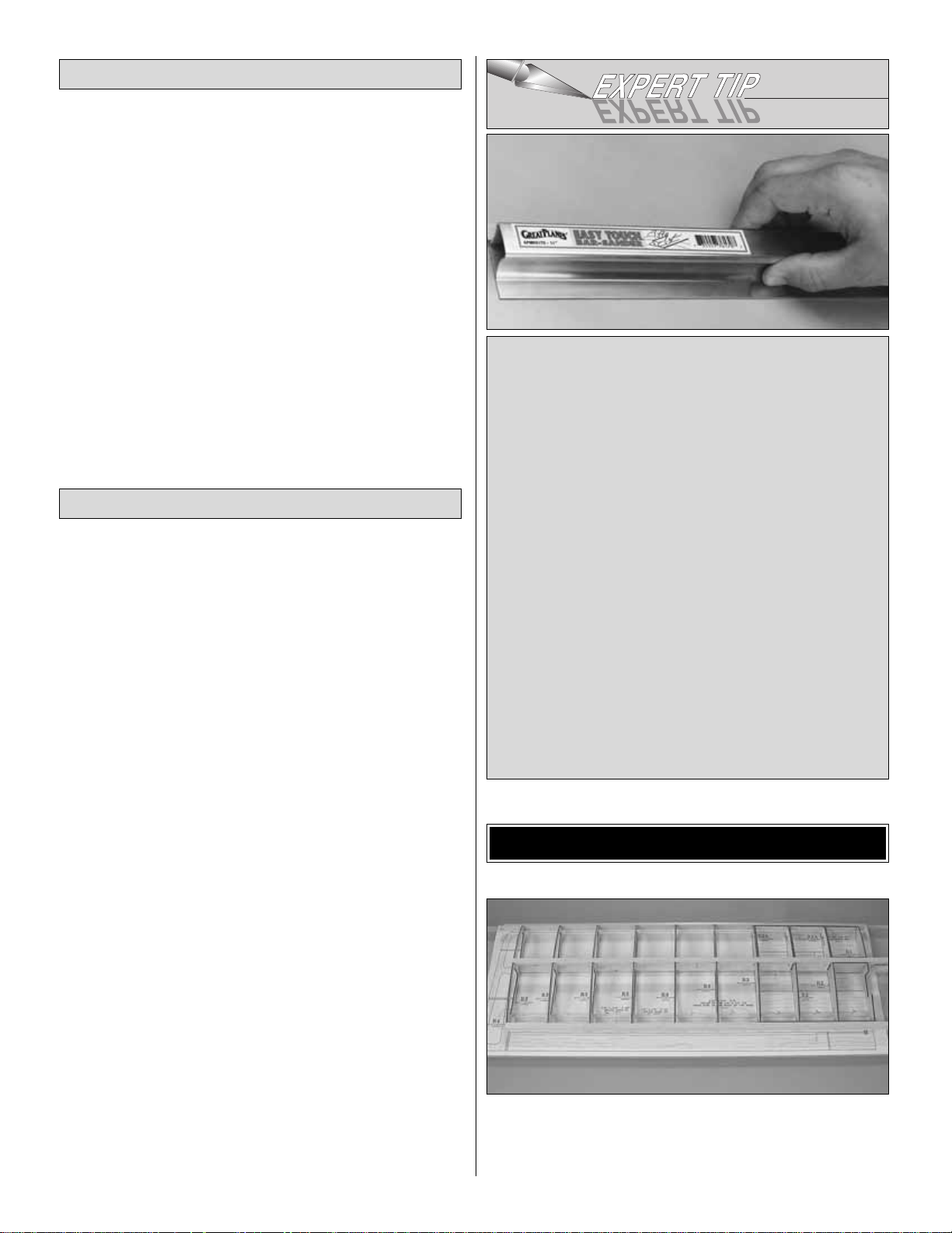
EASY-TOUCH BAR SANDER
A flat, durable, easy to handle sanding tool is a necessity
for building a well finished model.Great Planes makes a
complete range of Easy-Touch Bar Sanders and
replaceable Easy-Touch Adhesive-backed Sandpaper.
While building the Rapture 40, two 5-1/2" [140mm] Bar
Sanders and two 11" [280mm] Bar Sanders equipped
with 80-grit and 150-grit Adhesive-backed Sandpaper
were used.
5-1/2" [140mm] Bar Sander (GPMR6169)
11" [280mm] Bar Sander (GPMR6170)
12' [3.66m] roll of Adhesive-backed 80-grit sandpaper
(GPMR6180)
12' [3.66m] roll of Adhesive-backed 150-grit sandpaper
(GPMR6183)
Assortment pack of 5-1/2" [140mm] strips (GPMR6189)
Top Flite 320-grit (TOPR8030, 4 sheets) and 400-grit
(TOPR8032, 4 sheets) wet-or-dry sandpaper is also
recommended for finish sanding.
Optional Supplies & Tools
Covering & Covering Tools
4
Page 5
Building Board (GPMR6948) is suggested.A piece of 2' x 4'
[610 x 1220mm] Celotex®ceiling tile is also suitable. Of
course, the building board won’t be flat unless the
workbench beneath it is flat as well.
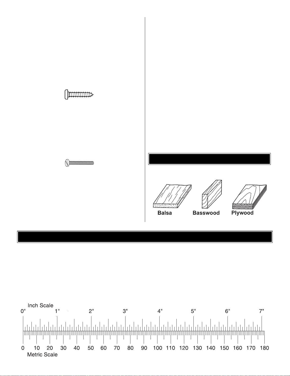
• There are two types of screws used in this kit:
Sheet metal screws are designated by a number and
a length.
For example #6 x 3/4" [20mm]
This is a number six screw that is 3/4" [20mm] long.
Machine screws are designated by a number, threads per
inch, and a length.SHCS is just an abbreviation for “sock et
head
cap screw” and that is a machine screw with a socket head.
For example 4-40 x 3/4" [20mm]
This is a number four screw that is 3/4" [20mm] long with
forty threads per inch.
• When you see the term
test fit
in the instructions, it
means that you should first position the part on the
assembly without using any glue, then slightly modify or
custom fit
the part as necessar y for the best fit.
• Whenever the term
glue
is written you should rely upon
your experience to decide what type of glue to use.When a
specific type of adhesive works best for that step, the
instructions will make a recommendation.
• Whenever just
epoxy
is specified you may use either
30-minute (or 45-minute) epoxy or 6-minute epoxy. When
30-minute epoxy is specified it is highly recommended that
you use only 30-minute (or 45-minute) epoxy, because you
will need the working time and/or the additional strength.
•
Photos and sketches
are placed before the step they
refer to. Frequently you can study photos in following steps
to get another view of the same parts.
• Not all die-cut parts have a name, or their complete
name stamped on them, so refer to the
“Die-Cut Patterns”
on page 6 for identification. When it’s time to remove the
parts from their die sheets, if they are difficult to remove, do
not force them out. Instead, use a sharp #11 blade to
carefully cut the part from the sheet, then lightly sand the
edges to remove any slivers or irregularities. Save some of
the larger scraps of wood.
TYPES OF WOOD
5
1/64" = .4 mm
1/32" = .8 mm
1/16" = 1.6 mm
3/32" = 2.4 mm
1/8" = 3.2 mm
5/32" = 4.0 mm
3/16" = 4.8 mm
1/4" = 6.4 mm
3/8" = 9.5 mm
1/2" = 12.7 mm
5/8" = 15.9 mm
3/4" = 19.0 mm
1" = 25.4 mm
2" = 50.8 mm
3" = 76.2 mm
6" = 152.4 mm
12" = 304.8 mm
18" = 457.2 mm
21" = 533.4 mm
24" = 609.6 mm
30" = 762.0 mm
36" = 914.4 mm
METRIC CONVERSIONS
Page 6
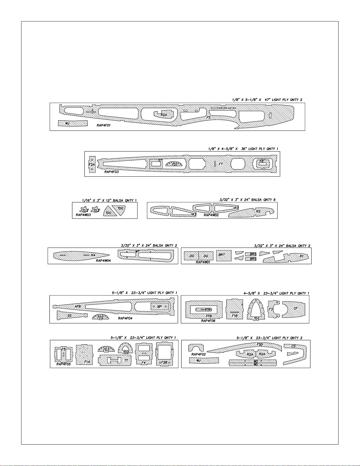
6
DIE-CUT PATTERNS
Page 7
❏ 1. Unroll the full-size plan sheet and reroll it inside out to
help it lay flat. Cut the fin plan from the rest of the plan, or
position the plan so the fin is over your b uilding board.Cover
the fin plan with Great Planes Plan Protector or wax paper
so glue will not adhere to the paper.
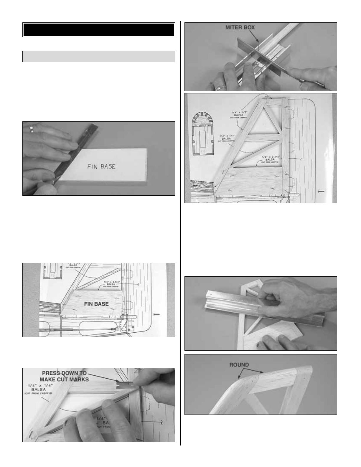
❏ 2. Use the pattern on the plan to cut the fin base from
the 1/4" x 2-1/4" x 24" [6.4 x 57 x 610mm] balsa sheet.
Repositionable spray adhesive may be used to temporarily
stick the pattern to the balsa sheet, or the pattern can
simply be traced onto the sheet. Use a straightedge and a
hobby knife to cut out the part.
❏ 3. Pin the fin base to the building board over its location
on the plan.
❏ 4. Build the rest of the fin framework from a 1/4" x 1/2" x
36" [6.4 x 13 x 914mm] balsa stick and a 1/4" x 1/4" x 36" [6.4
x 6.4 x 914mm] balsa stick.Use medium CA to glue the parts
together and use T-pins to hold them down as you go. Hint:
The easiest, most accurate way to cut the small sticks is to
place the stick over the structure; use a single-edge razor
blade to make cut marks, then cut the rest of the way through
the stick over your workbench. A miter box is also helpful for
cutting 90° angles on some of the larger balsa sticks.
❏ 5. Remove the fin from the plan. Use a bar sander with
80-grit sandpaper to sand both sides flat and round the tip
and leading edge. Follow with 220-grit sandpaper. Final
sanding will be done later.
Build the Fin & Rudder
BUILD THE T AIL SURF A CES
7
Page 8
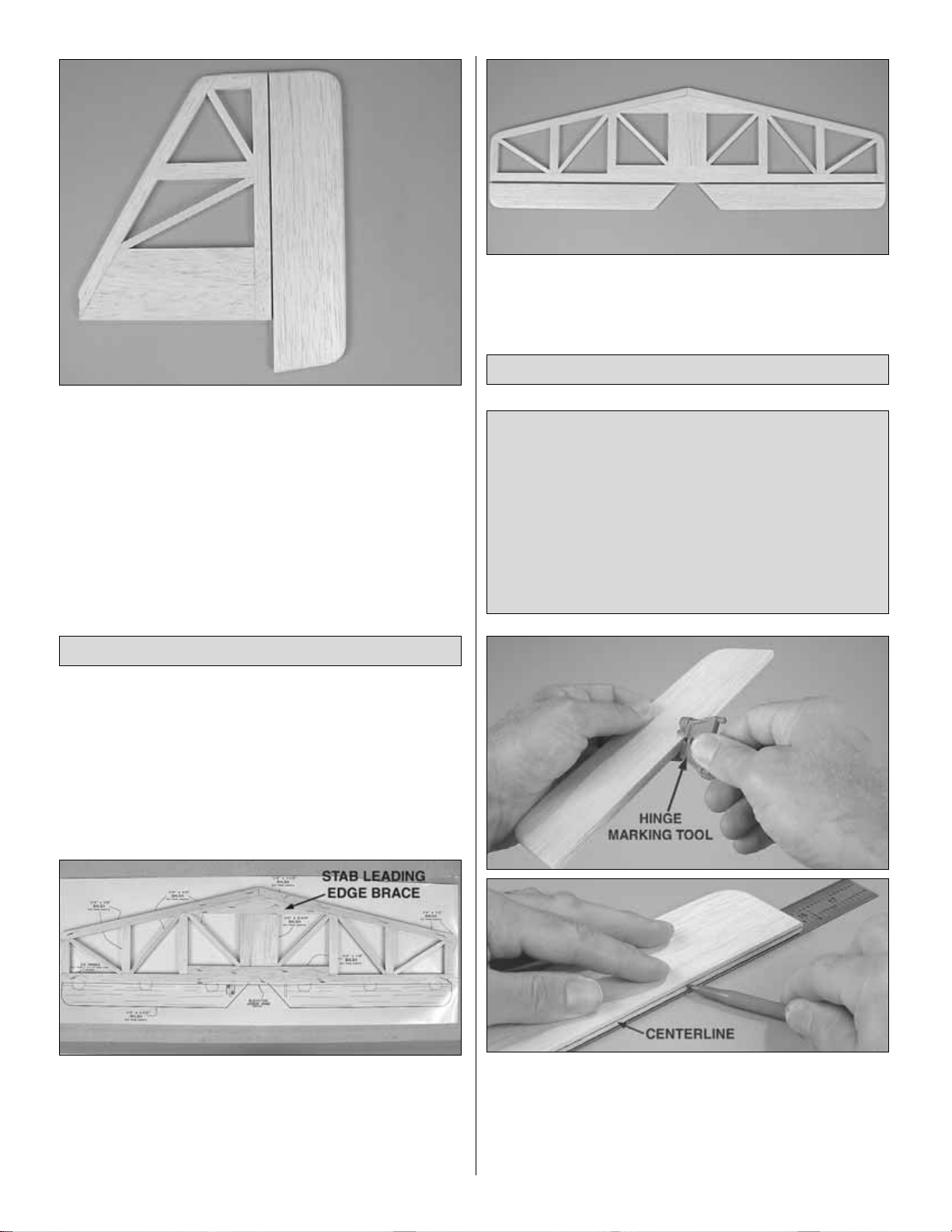
❏ 6. Make the rudder as shown on the plan from the
remainder of the 1/4" x 2-1/4" x 24" [6.4 x 57 x 610mm]
balsa sheet used to make the fin base.Do not cut the “V” in
the leading edge until instructed to do so.
Set the fin and rudder aside for now.
❏ 1. Cut out the stab plan or position the plan so it is over
your flat building board. Cover with Great Planes Plan
Protector or wax paper.
❏ 2. The same way you cut the fin base for the fin, use the
stab leading edge brace template on the plan to cut the
stab leading edge brace from the 1/4" x 1-1/2" x 36" [6.4 x
38 x 914mm] balsa stick. Pin the brace to the plan.
❏ 3. Finish building the stab from the remainder of the 1/4"
x 1/4" x 36" [6.4 x 6.4 x 914mm] balsa stick and the
remainder of the 1/4" x 2-1/4" x 24" [6.4 x 57 x 610mm]
balsa sheet used to build the fin, an additional 1/4" x 1/4" x
36" [6.4 x 6.4 x 914mm] balsa stick and two more 1/4" x 1/2"
x 36" [6.4 x 13 x 914mm] balsa sticks.
❏ 4. Make both elevators from the remainder of the 1/4" x
1-1/2" x 36" [6.4 x 38 x 914mm] balsa sheet used to make
the stab leading edge brace. Do not cut the “V” on the
leading edge until instructed to do so.
❏ 1. Use a Great Planes Precision Hinge Marking Tool
(GPMR4005) to mark the centerline all the way down the
leading edge of the rudder. If you don’t have a Hinge
Marking Tool, use a fine-point ballpoint pen to mark the
centerline as shown.The pen or the rudder may have to be
raised from the workbench so the line will be on center.
NOTES ABOUT CA HINGES
This kit is supplied with CA hinge material consisting of a
3-layer lamination of Mylar and polyester specially made
for hinging model airplanes.When properly installed, this
type of CA hinge provides the best combination of
strength, durability and easy installation. We use these
hinges on all our models, but it is essential to install them
correctly. Follow the hinging instructions in this manual for
the best result. The techniques shown have been
developed to ensure thorough and secure gluing.
Hinge the Elevators & Rudder
Build the Stab & Elevators
8
Page 9
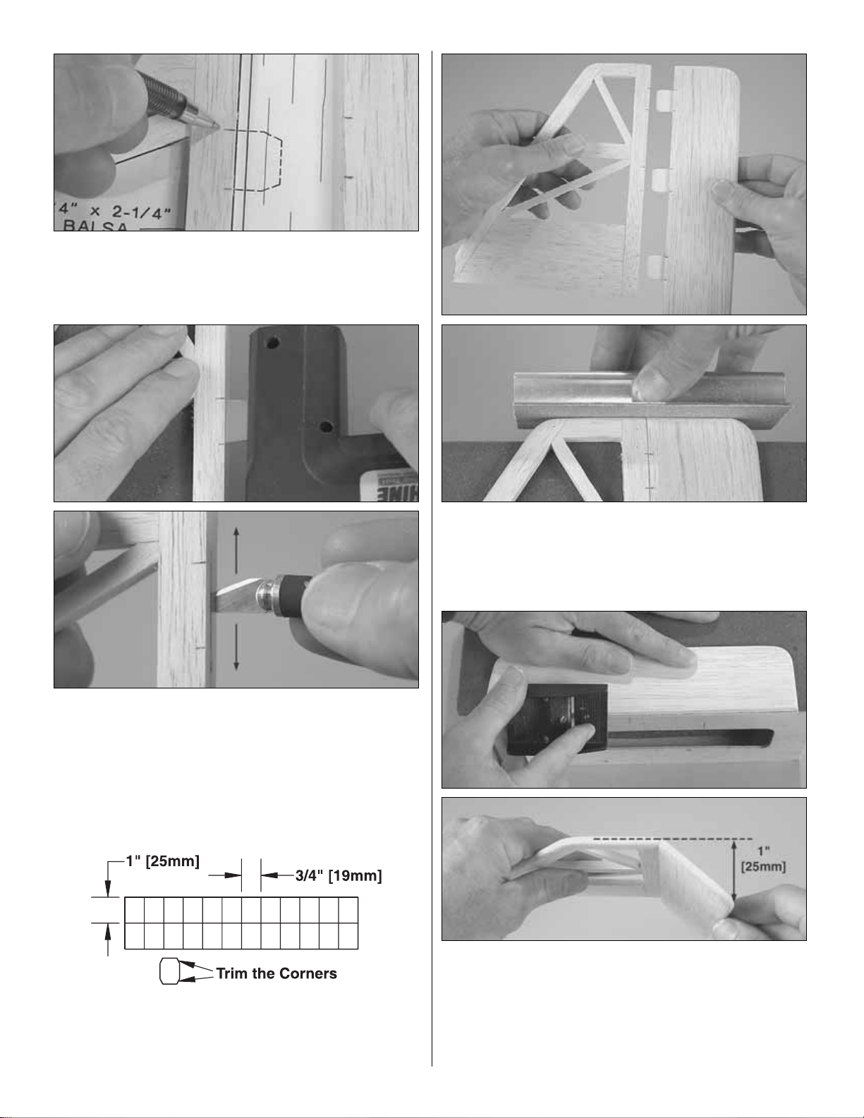
❏ 2. Mar k the locations of the hinge slots on the fin and
rudder where shown on the plan.
❏ 3.Use a Great Planes Slot Machine to cut hinge slots on
the centerlines at the marks. If you do not have a Slot
Machine, use a #11 hobby blade to cut the hinge slots .Start
by making a small slit.Then, working in small increments, go
a little deeper moving the blade back and forth. Note that it’s
the back of the blade that does the work.
❏ 4. Cut three 3/4" x 1" [19 x 25mm] CA hinges from the
supplied 2" x 9" [50 x 230mm] CA hinge strip. Snip off the
corners so they go in easier.
❏ 5. Test fit the rudder to the fin with the hinges. Make
adjustments where necessary for a good fit. Hint: Now that
the rudder and fin are together (temporarily), this would be
the perfect opportunity to align the tip of the fin and rudder
by sanding them to match each other.
❏ 6.Using the centerline as a guide, refer to the plan to get
the correct angle, then shape the leading edge of the rudder
to a “V.” The best tool for this is the Master Airscrew razor
plane (MASR1510). If you don’t have a razor plane a bar
sander with 80-grit sandpaper can be used instead.The “V”
doesn’t have to be sharp, but make certain you can get 1"
[25mm] of both right and left rudder throw.
9
Page 10
❏ 7. Set the fin and r udder aside. Mark the centerlines and
hinge locations and cut the hinge slots on both elevators
and the stab the same way, but don’t cut the “V” until
instructed to do so.
❏ 8. With the elevators temporarily connected to the
stabilizer with the hinges, determine which side looks best.
Write “bottom” on the other side of the center of the stab.
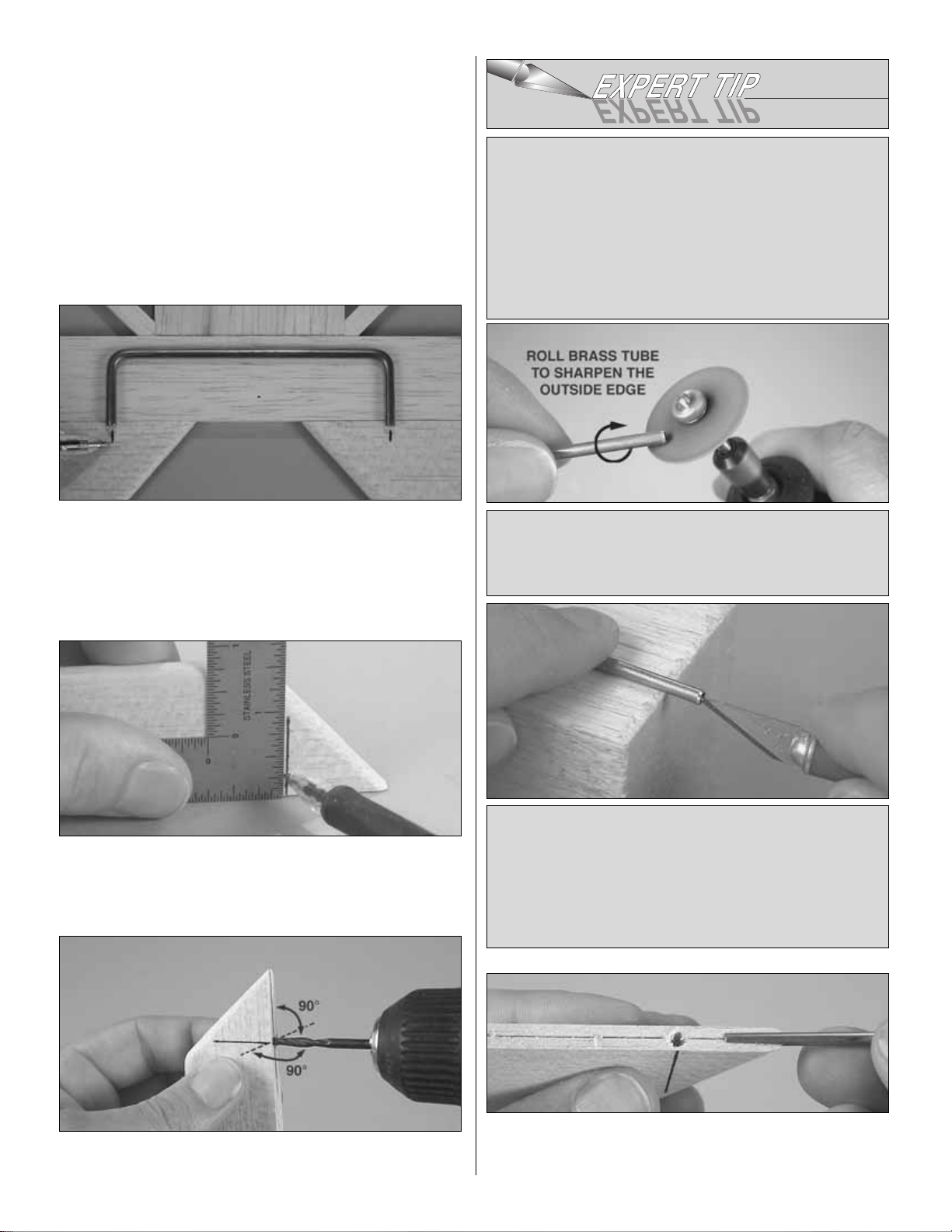
❏ 9. Place the joiner wire on the bottom of the stab as
shown. Use a ballpoint pen to mark the location of the ends
of the joiner wire where it will go into the elevators.
❏ 10. Extend the lines across the bottom of the elevator
using a small square.
❏ 11.Drill a 9/64" [3.6mm] (or 1/8" [3.2mm]) hole 1" [25mm]
deep into both the elevators centered on the lines.
❏ 12.Use a 1/8" [3.2mm] brass tube sharpened on the end
or a hobby knife to cut a groove in both elevators to
accommodate the joiner wire.
Use a hobby knife with a #11 blade to sharpen the inside
of the tube by rolling it on a wood block.
The tube can be turned either by hand or by an electric
drill. After the hole has been cut the material will usually
stick inside the tube. The balsa “plug” can be removed
with a wire or the next size smaller tube.
Sharpen the outside of the tube using a fiber reinforced
cut-off wheel or a metal file. If using a cut-off wheel, be
certain to use the reinforced variety and always wear
safety glasses.
HOW TO SHARPEN A BRASS TUBE FOR
CUTTING BALSA
Often, using a brass tube sharpened on the end to cut
holes (or grooves) in balsa provides a much cleaner,
more accurate hole than would a regular drill bit. The
sharpening procedure below works on any size of hobby
tubing (available from K&S at hobby shops, craft stores
and hardware stores).
10
Page 11
❏ 13. Test fit the elevators to the stabilizer with the joiner
wire. Make any adjustments necessary for a good fit.
❏ 14. The same as was done for the rudder, bevel the
leading edge of both elevators. Make sure you can get 1/2"
[13mm] of both up and down elevator throw.
Set the elevators and rudder aside while building the wing.
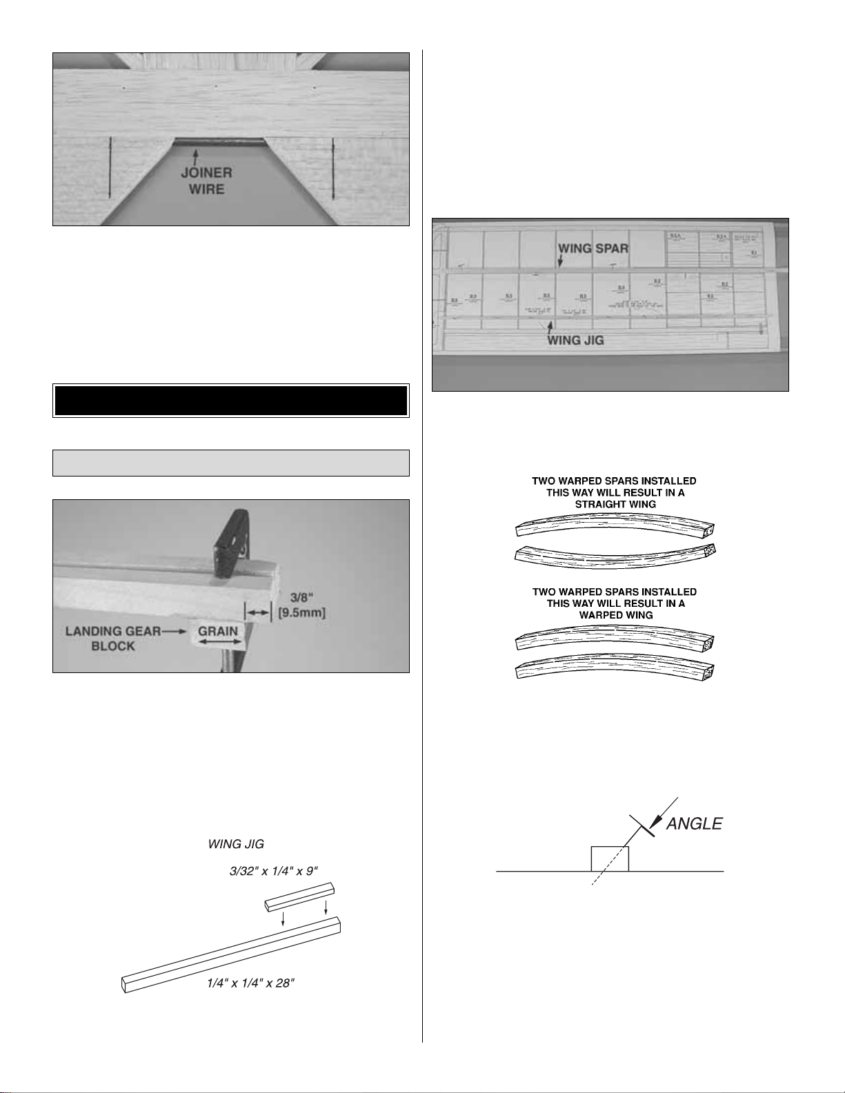
❏ 1. Use 30-minute epoxy to glue a 1/2" x 3/4" x 3/4" [13 x
19 x 19mm] maple landing gear block to the top of a 1/2"
x 3/4" x 6-1/4" [13 x 19 x 160mm] landing gear rail. The
block should be 3/8" [10mm] from one end of the rail and the
wood grain on the block should run the same direction as
the rail. Make another assembly the same way. Set the
assemblies aside and get to work on the rest of the wing
while the epoxy hardens.
❏ 2. Cut 9" [230mm] from a 3/32" x 1/4" x 24" [2.4 x 6.4 x
610mm] balsa stick. Cut 2" [50mm] from a 1/4" x 1/4" x 30"
[6.4 x 6.4 x 760mm] balsa stick.Glue the 9" [230mm] stick on
top of one end of the 28" [710mm] stick to make the wing jig.
Start with the left panel so yours looks like the photos
the first time through.
❏ ❏ 3. Position the left wing panel plan over your flat b uilding
board and cover it with Plan Protector or wax paper.
Refer to this photo for the following three steps.
❏ ❏ 4. Pin the wing jig over its location on the plan with the
ends protruding beyond the root and tip ribs.The end with the
9" [230mm] piece goes toward the root end of the wing panel.
❏ ❏ 5.Inspect the four 3/8" x 3/8" x 30" [9.5 x 9.5 x 760mm]
balsa wing spars included with this kit. Note any warps that
may be present.If any of the spars are warped, pair them up
as shown in the sketch at the top to cancel out any warps.
❏ ❏ 6. Pin one of the wing spars over its location on the
plan being certain, if necessar y, to place it so any warp will
be cancelled out by the top spar. Note that the pins should
be inserted at an angle so they do not interfere with the top
spar when it is added later on. Also note that the tip of the
spar should “end” at the outer edge of r ib R3 but the root
end of the spar may extend beyond the root rib.
Build the Wing Panels
BUILD THE WING
11
Page 12
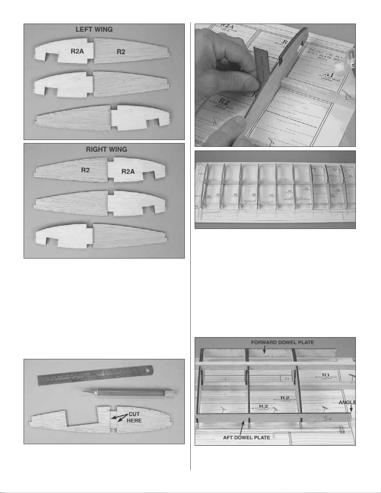
❏ ❏ 7. Use medium CA or epoxy to glue the die-cut 1/8"
[3.2mm] plywood R2A rib doublers to the correct side of
three die-cut 3/32" [2.4mm] balsa R2 ribs as shown in the
photo for the wing panel you are working on.
❏ ❏ 8. Use a straightedge and a hobby knife to cut partway
through the outside of rib R1 between the spar notches
as shown.
❏ ❏ 9. Using a small square to keep the ribs vertical, glue
all the ribs except ribs R1 to the bottom spar. Also be
certain the ribs are contacting the wing jig as you go.
❏ ❏ 10. Glue the top spar to the r ibs, again making sure
the ribs remain vertical. Don’t forget to position the top spar
to cancel out any warp that may have been in the bottom
spar.If any of the ribs lift from the wing jig, use T-pins to hold
them down.
❏ ❏ 11. Glue the die-cut 1/8" [3.2mm] plywood forward
and aft dowel plates into position. Note the angle on one
end of the dowel plates.This is the end that goes on R1.
12
Page 13
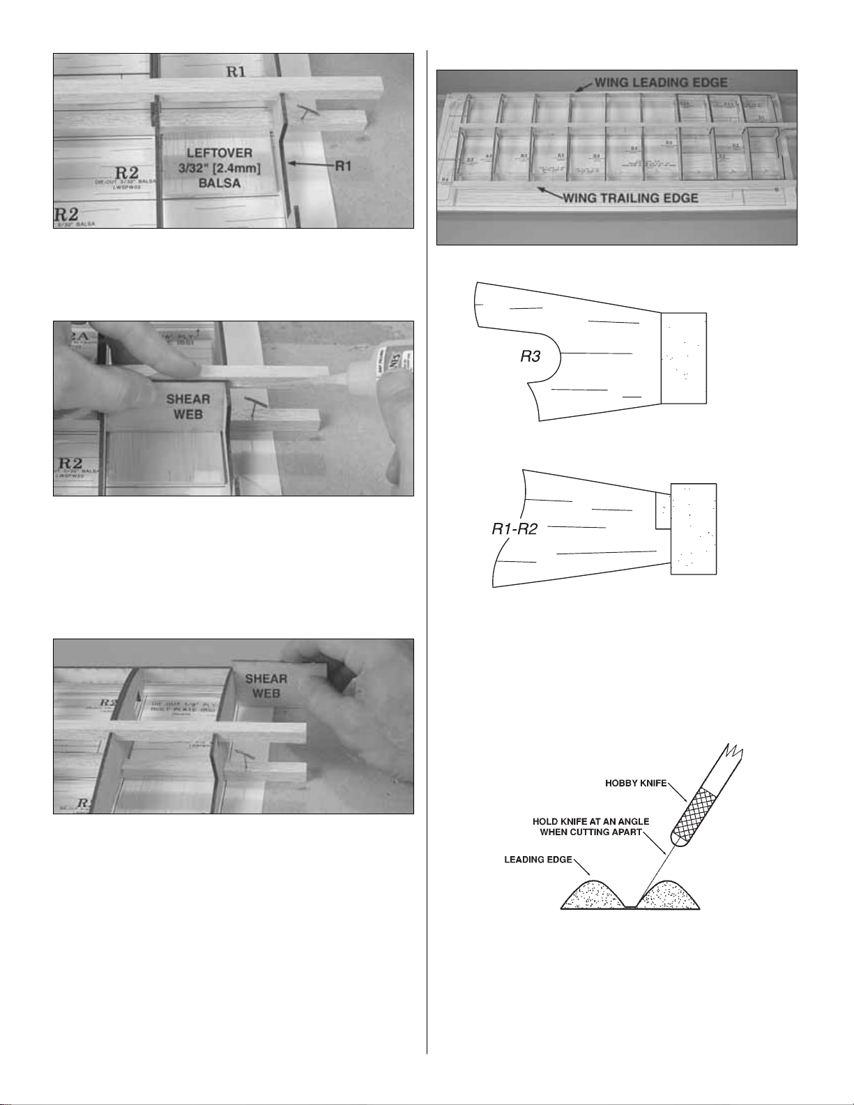
❏ ❏ 12. Fit, but do not glue rib R1 into position. Place a
leftover piece of 3/32" [2.4mm] balsa on the plan against the
bottom spar.
❏ ❏ 13.Fit, but do not glue the die-cut 3/32" [2.4mm] balsa
shear web (DG) between R1 and R2. Make sure the shear
web is installed with the angled end contacting R1 so that
the top of R1 is slanting outward toward the wing tip. Glue
R1 to the top and bottom spars only.
❏ ❏ 14. Remove the shear web.Flip it over, then use it to
check the angle of R1 as you glue it to the forward and aft
dowel plates.
❏ ❏ 15. Using the 3/32" [2.4mm] balsa shim to raise the
shear web from the plan, glue the shear web to the back of
the spars. Use the same procedure to glue another shear
web to the front of the spars.Be careful not to inadvertently
glue the leftover balsa shim to the spars or shear web.
❏ ❏ 16. Lightly sand the front of the dowel plates to trim
any ribs that may be protruding.
Refer to this photo for the following three steps.
❏ ❏ 17.Glue the 3/8" x 3/4" x 30" [2.4 x 19 x 760mm] balsa
wing trailing edge into position. Note that the trailing edge
should be centered vertically on all the ribs.This means that
the top and bottom of all the R3 ribs will be even with the top
and bottom of the trailing edge, but there will be a 3/32"
[2.4mm] difference between the top and bottom of the other
ribs and the top and bottom of the trailing edge.
❏ ❏ 18. Use a hobby knife to separate the 30" [760mm]
shaped leading edges from each other as shown in
the sketch.
❏ ❏ 19.Glue one of the leading edges into position.Be certain
the leading edge is centered vertically on all the ribs and the
dowel plate.Note that the tip of the leading edge should extend
approximately 1-1/2" [38mm] beyond R3 at the wing tip.
13
Page 14
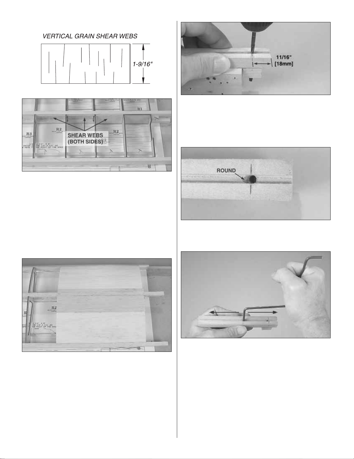
❏ ❏ 20. Cut four 1-9/16" [39mm] vertical grain shear
webs from the 3/32" x 3" x 24" [2.4 x 76 x 609mm] hard
balsa sheet.Tr im the ends of the shear webs to fit between
the ribs where shown on the plan.The same as when gluing
the die-cut shear webs into position, use a piece of leftover
3/32" [2.4mm] balsa to raise the shear webs from the plan.
Note: Remove any T-pins that are in the way.
❏ ❏ 21. Remove any T-pins that are in the bottom spar
between R1 and the last R2. Sheet the top of the wing with
a 3/32" x 3" x 36" [2.4 x 76 x 914mm] balsa sheet.
❏ ❏ 22. Now the wing may be removed from the building
board. Use part of another 3/32" x 3" x 36" [2.4 x 76 x
914mm] balsa sheet to sheet the bottom of the wing, but
only between the trailing edge and the main spar.
❏ ❏ 23.Drill a #20 or 5/32" [4mm] hole through the landing
gear rail and the landing gear block 11/16" [18mm] from the
end. (The wire is 5/32" [4mm], but using a #20 drill, which is
slightly larger than 5/32" [4mm], will make the gear a little
easier to install and remove during construction.)
❏ ❏ 24.Use a hobby knife to round the edge of the hole to
accommodate the bend in the gear.
❏ ❏ 25. Slightly widen the groove in the rail by pushing one
end of the gear back and forth.This will also make it easier to
install and remove the gear during test fitting and assembly.
❏ ❏ 26. Test fit the gear in the rail. Make adjustments
where necessary.
❏ ❏ 27.Use 30-minute epoxy to glue the previously prepared
landing gear rail assembly into position on the bottom of the
wing. Be certain to get a secure glue joint between the
maple landing gear block and the plywood doubler (excess
glue isn’t required–good contact is the way to a strong joint).
14
Page 15

❏ ❏ 28. With the gear in the rail, use a ballpoint pen to
mark the leading edge of the wing at both ends of the gear.
These marks will note the ends of a groove that will be cut
in the sheeting for the gear.
❏ ❏ 29.Sheet the remaining open section of the bottom of
the wing panel with leftover 3/32" [2.4mm] balsa sheeting.
❏ ❏ 30. Cut off the remaining portion of the spars, leading
edge and trailing edge so they are even, or nearly even with
R1.Do not cut off the leading edge at the tip.Sand the spars
and sheeting even with end ribs.Also sand the trailing edge
to match the shape of the ribs.
❏ ❏ 31. Using the partially cut guide lines on R1, cut the
rest of the way through and remove the section of balsa
between the spars.
❏ ❏ 32. Test fit, then glue together all the die-cut 3/32"
[2.4mm] balsa parts of the wing tip. Be certain to make a
right or a left tip depending on which wing panel is currently
under construction.
❏ ❏ 33. Glue the completed wing tip assembly to the end
of the wing. Round the leading edge as shown in the photo
and on the plan. Add the tip bracing from leftover 1/4"
[6.4mm] balsa.
15
Page 16

❏ ❏ 34.Cut a 1/2" [13mm] strip from the top sheeting over
the opening for the aileron servo.
❏ 35. Return to step 4 and build the right wing panel. Be
sure to place the right panel wing plan over your building
board so as not to accidentally build another left panel.
Again, do the left wing first.
❏ ❏ 1. Mark one of the basswood shaped wing trailing
edges where the left aileron torque rod will go through.
❏ ❏ 2.Use a rotary tool or a hobby knife to cut a groove to
accommodate the left aileron torque rod.
❏ ❏ 3.Cut a matching groove in the wing trailing edge.
❏ ❏ 4. Roughen the plastic bearing tube on the torque rod
with coarse sandpaper.Use thick or medium CA to glue the
tube into the shaped trailing edge. Use caution not to
inadvertently get any glue inside the bearing tube.Hint: Add
a small dab of petroleum jelly to the end of the bearing tube
to keep epoxy from getting in.
❏ ❏ 5.Glue the shaped wing trailing edge to the wing. The
wing trailing edge should extend past the root end of the
wing by approximately 1/32" [0.8mm] so the angle can be
sanded to match R1.
❏ ❏ 6. Sand the top, bottom and end of the shaped wing
trailing edge as necessary to blend with the rest of the wing.
❏ ❏ 7. Prepare the other shaped wing trailing edge for the
right wing and glue it into position the same way. Note: Be
certain to cut the groove in the correct location so as not
inadvertently make another left side!
❏ ❏ 8.Fit one of the 24" [609mm] shaped balsa ailerons up
to the wing. If necessar y, trim one end of the aileron so there
will be an approximately 3/32" [2.4mm] gap on both ends.
❏ ❏ 9.The same as was done for the elevators, mark the
location for the torque rod on the aileron, then drill a 1/8"
[3.2mm] hole and cut the groove.Mark and cut all the hinge
slots as well.
❏ ❏ 10. Cut eight more 3/4" x 1" [19 x 25mm] CA hinges.
Test fit the aileron to the wing with four of the hinges. Make
adjustments where necessary.
❏ ❏ 11. Remove the aileron from the wing and shape the
leading edge to a “V” as shown on the plan.
Make the Ailerons
16
Page 17

❏ ❏ 12. Test fit the aileron to the wing and torque rod with
the hinges. Use the torque rod to move the aileron up and
down to make sure you can achieve 1/2" [13mm] of both up
and down aileron throw as shown in the control throws chart
on page 36.
❏ 13. Make the aileron for the right wing the same way.
❏ 1. Use medium CA or epoxy to glue together three die-
cut 1/8" [3.2mm] plywood wing joiners (four are supplied
but only three are used).
❏ 2.Test fit the wing joiner in one wing half, then the other.
Test join the wings with the joiner. Make any adjustments
necessary for a good fit. (Sometimes the ends of the wing
require a little “fine tuning”with a bar sander or the edges of
the joiner might need to be sanded a little.)
❏ 3. With the wings temporar ily fit together, lay one wing
panel flat on your workbench and measure the distance
between the bottom of the other panel under the bottom
spar at the tip.The distance should be 2-3/8" [60mm] plus or
minus 3/8" [10mm]. If you are not able to achieve this
measurement within the 3/8" [10mm] tolerance, separate
the wing halves and look for an ything that may interfere with
the fit such as glue blobs inside the wings where the joiner
goes. Note: It is more important to have a good fit between
the joining wing panels than it is to have exactly 2-3/8"
[60mm] of dihedral.
❏ 4. Gather all the items required for joining the wing: 30-
minute epoxy, a mixing cup and mixing stick, an epoxy
brush, masking tape, paper towels and denatured alcohol
(for clean up).
Note: When joining cr itical components such as the wing
halves, it is imperative to coat all joining parts with
epoxy. In other words, don’t coat only one of the
contacting end ribs. Coat the end ribs of both wing
panels. Similarly, don’t just coat the joiner. Also coat the
insides of the wing where the joiners go.
Join the Wing
17
Page 18

❏ 5. Prepare approximately 3/4 oz. [25cc] of 30-minute
epoxy. Use a piece of wire or a small dowel to coat the
inside of one of the wing halves where the joiner goes and
the rib on the end of the panel. Coat one half of the joiner,
then insert the joiner into the panel. Working quickly before
the epoxy starts to harden, coat the inside and the end of
the other panel and the protruding end of the joiner. Fit the
wings together.Wipe awa y e xcess epo xy as it squeezes out.
Use several strips of masking tape to tightly hold the wing
halves together, wiping away excess epoxy as it is forced
from between the panels.Be certain both panels accurately
align–especially the leading and trailing edges. Do not
disturb the wing until the epoxy has hardened.
Fit both landing gears at the same time.
❏ 1. Remove all the masking tape. Using the mar ks made
earlier on the leading edge as a guide, cut the slots in the
bottom sheeting for both landing gears. Test fit the gear.
Make adjustments where necessary.
❏ 2. Temporarily mount the landing gear with four nylon
landing gear straps and eight #2 x 1/2" [13mm] screws. Drill
1/16" [1.6mm] holes for the screws.Use a fine-point ballpoint
pen to draw the outline of the straps onto the sheeting.
❏ 3.Remove the screws and straps.Use a hobby knife to cut
and remove the sheeting around the lines marking the straps.
Hint: A 5/16" [8mm] brass tube sharpened on the end may be
used to cut the sheeting over the ends of the straps.
❏ 4. Refit the gear with the straps and screws.
Finish the Wing
18
Page 19

❏ 5.Glue the die-cut plywood aileron servo tray to the top
of the wing centered over the servo opening.
Set the wing aside and get started on the fuselage.
Note: Unless otherwise noted, all parts used to build the
fuselage are die-cut plywood.
❏ 1. Use medium CA to glue one of the wing saddle
doublers to one side of one of the fuselage sides. Glue the
other wing saddle doubler to the other side of the other
fuselage side. Be certain to make a right and a left by
making two
mirrored
assemblies.
❏ 2.Place the bottom view of the fuselage plan over your flat
building board and cover it with Plan Protector or wax paper.
❏ 3.Glue the back of F1A to the front of F1B. From now on
this assembly will be referred to as the
firewall
.
❏ 4. Dr ill 1/16" [1.6mm] holes through the punchmarks in
F2B. Drill 3/32" [2.4mm] holes through the punchmarks in
the tank tray retainer (TTR).
❏ 5. Glue small pieces of leftover plywood to the front of
F2B over the 1/16" [1.6mm] holes you drilled. Glue F2A to
the front of F2B. Redr ill the 1/16" [1.6mm] holes. From now
on this assembly will be referred to as F2.
Frame the Fuselage
BUILD THE FUSELAGE
19
Page 20

❏ 6. Use a ballpoint pen and a straightedge to draw a
vertical line on the front of the firewall connecting the
punchmarks in the middle. Drill 5/32" [4mm] holes through
the remaining four punchmarks. Press four 6-32 blind nuts
partway into the holes on the back of the firewall.Add a few
drops of medium CA to the blind nuts where they will contact
the firewall, then tap the blind nuts the rest of the w a y in with
a hammer. Wipe away excess CA. If using the O.S.®MAX
.40 or .46 FX, drill the 3/16" [4.8mm] hole in the back of the
firewall for the throttle pushrod tube the rest of the way
through. If using a different engine do not drill the hole (the
hole for the throttle pushrod will be drilled later).
❏ 7. Pin the aft fuselage top upside-down to the building
board over its location on the plan.You’ll know it’s upsidedown when the front aligns with the plan.
❏ 8.Glue the die-cut plywood formers F2 through F6 to the
aft fuselage top.Do your best to get the formers vertical, but
if they aren’t perfect the notches in the fuselage sides will
square ‘em up anyway.
❏ 9. Join, but do not glue the right and left fuselage sides
to the fuselage top and formers. Use some of the leftover
balsa sticks cut from the ends of the wing to hold the
fuselage sides to the fuselage top.
❏ 10. Use thin and medium CA to glue the fuselage sides
to the fuselage top and formers aft of F2. Do not glue the
fuselage sides to the fuselage top forward of F2. Making
sure all glue joints are tight and fit well is the way to a true
and square fuselage.
20
Page 21

❏ 11. Glue both wing bolt plate mounts to both sides of
the fuselage.The bottom of the plates should align with the
bottom of the wing saddles. Glue both wing bolt plates
together, then securely glue them into position.
❏ 12.Test fit, then glue the aft fuselage bottom into position.
❏ 13. Place the wing on the fuselage. Taking accurate
measurements, center the centerline of the wing (the glue
joint between the two joining halves) in the fuselage. Place
weights on top of the wing to hold it down.
❏ 14.Using the dowel holes in F2 as a guide, drill the holes
in the leading edge of the wing with a 1/4" [6.4mm] drill or a
1/4" [6.4mm] brass tube sharpened on the end. As the
fuselage sides have not been glued to the fuselage top
forward of F2, the sides can be spread apart if necessary to
accommodate the drill.
❏ 15. Use 30-minute epoxy and a few clamps to securely
glue the firewall into position.Be certain the top of the firewall
is fully contacting the fuselage top. Also note that the r ight
side of the firewall should be all the way back in the notch in
the fuselage side and the left side of the firewall should be all
the way forward in the notch in the fuselage side.
❏ 16. After the epoxy from the previous step has hardened
remove the clamps.Test fit, then glue the forward fuselage
bottom into position. Also glue the fuselage sides to the
fuselage top forward of F2.
❏ 17. The fuselage may now be removed from the building
board. Use a bar sander with 80-grit sandpaper to sand the
fuselage sides and top and bottom flat and even.
❏ 1.If the wing hasn’t yet been final sanded, go ahead and at
least sand the area around the dowel holes. The rest of the
wing can be final sanded later, but it will be easier to sand
around the dowel holes before the do wels hav e been installed.
❏ 2. Cut two 1-1/8" [29mm] wing dowels from the 1/4" x 6"
[6.4 x 150mm] hardwood dowel. Round one end of the
wing dowels.
❏ 3. Use 30-minute epoxy to glue the dowels into the front
of the wing with the rounded ends out. Be certain
Mount the Wing
21
Page 22

approximately 3/8" [10mm] of the dowels protrude from the
leading edge.
❏ 4. After the epoxy has hardened, place the wing on the
fuselage. Stick a T-pin into the center of the rear of the
bottom of the fuselage.Tie a loop in one end of a 40" [1m]
piece of non-elastic string such as monofilament or Kevlar
line (K+SR4575). Slip the loop in the str ing over the T-pin.
❏ 5. Fold a piece of masking tape over the string near the
other end and draw a sharp arrow on it.Slide the tape along
the string and align the arrow with one end of the wing as
shown in the photo. Swing the string over to the same
position on the other end of the wing. Pivot the wing and
slide the tape along the string until the arrow aligns with
both ends of the wing. Now the wing will be centered.
❏ 6. Bevel the front and both ends of one side of the bolt
plate (BP) as shown in the photo.Glue the bolt plate to the
bottom of the wing centered on the fuselage.
❏ 7. Recheck the wing alignment. Using the holes in the bolt
plate as a guide, drill #7 (.201" [5mm]) (or 13/64") holes
through the wing and wing bolt plate in the fuselage.Be certain
to hold the drill perpendicular to the bottom of the wing.
❏ 8. Remove the wing from the fuselage.Thread the holes
in the wing bolt plate with a 1/4-20 tap. Add a few drops of
thin CA to the threads in the holes and allow to fully harden.
Run the tap back through, then repeat the procedure one
more time.
❏ 9. Enlarge the bolt holes in the wing with a 17/64"
[6.4mm] or 1/4" [6.8mm] drill.Mount the wing to the fuselage
with two 1/4-20 nylon bolts to see how it all fits (the bolts
may be cut down to 1-1/4" [30mm]).
❏ 1. Cut both 3/16" [4.8mm] gray plastic pushrod guide
tubes to a length of 18-1/2" [470mm]. Use coarse
sandpaper to sand the guide tubes so glue will adhere.
Insert the tubes through the holes in the fuselage formers as
shown on the plan. Note that the tubes cross between
formers F4 and F5.
Install the Guide Tubes, Fuel Tank,
& Engine
22
Page 23

❏ 2.Mix a small batch of 30-minute epoxy and microballoons.
Use the mixture to glue the guide tubes in the exit slots in
the back of the fuselage. Be sure to build up a small fillet
around both guide tubes on the inside and outside of the
fuselage. Allow the epoxy to fully harden.
❏ 3. Use medium CA to glue the guide tubes to the rest of
the formers. After the epoxy from the previous step has
hardened, use coarse sandpaper to sand the guide tubes
even with the fuselage sides.
❏ 4. Cut the servo rails from the 1/4" x 3/8" x 9" [6.4 x 9.5 x
230mm] basswood stick to fit in the slots in the fuselage sides .
Install the rails, but glue only the front rail into position.
❏ 5. Temporarily install two or three servos on the rails.
Using the servos to set the correct spacing, glue the aft rail
into position. Be sure to leave a small space between the
servos and the rails so the servos can be removed.After the
glue hardens remove the servos.
❏ 6. Assemble the fuel tank (not included) according to the
instructions that came with it.Mount the fuel tank to the tank
tray (TT) with a #64 rubber band and a sheet of 1/4"
[6.4mm] R/C foam rubber in between.
❏ 7. Temporarily mount the tank tray in the fuselage with
the tank tray retainer and two #2 x 1/2" [13mm] scre ws.Note
that the tab on the front of the tank tray keys into the notch
in the back of the firewall.
❏ 8. Cut the spreader bar from both engine mount halves.
❏ 9. Temporarily mount the engine mount to the firewall
with four 6-32 x 1" [25mm] socket head cap screws and #6
lock washers and #6 flat washers.
❏ 10.Drill 15/64" [6mm] (or 1/4" [6.4mm]) holes through the
firewall for the fuel lines. Hint: If the engine mount is in the
way, draw the outline of the inside of the engine mount on
the firewall.Remove the mount, then drill the holes.
23
Page 24

❏ 11.Use epoxy to glue the cheek supports (CS) to the inside
of both fuselage sides in front of the firewall. With the engine
resting on the engine mount, test fit, then glue the cheek floor
into position as you squeeze the fuselage sides to it. Make
certain the cheek floor doesn’t interfere with the engine.
❏ 12. Mount a 2-1/2" [64mm] spinner (not included) and
propeller to the engine. Place the engine on the mount.
Adjust the spacing of the mount halves to fit the engine, then
temporarily tighten the screws. Position the engine on the
mount so there will be an approximately 1/8" [3mm] space
between the spinner and fuselage sides. Use a Great
Planes Dead Center engine mount hole locator or a wire
sharpened on the end to mark the engine mounting holes
on the mount.
❏ 13. Remove the engine and mount from the fuselage. Drill
3/32" [2.4mm] holes through the engine mount at the marks
you made. Re-mount the engine mount to the firewall, then
mount the engine to the mount with four #4 x 3/4" [19mm]
screws and #4 flat washers and lock washers. Center the
engine mount from side-to-side on the centerline drawn down
the firewall, then tighten the screws. Hint: Some modelers
prefer machine-thread screws rather than sheet metal scre ws
for mounting their engines.If this is your preference, drill #43
[2.2mm] holes and use a 4-40 tap to cut threads into the
holes. Mount the engine with four 4-40 x 1" [25mm] screws
(not included), #4 lock washers and flat washers.
❏ 14. If using the O.S.MAX .40 or .46 FX engine the hole
in the firewall and formers f or the throttle pushrod guide tube
are already in the correct location.If using a different engine
the hole in the firewall for the guide tube might have to be
relocated to align with the carburetor arm on the engine. If
necessary , determine where a new hole is to be drilled, then
drill a 3/16" [4.8mm] hole.
❏ 15. Cut one of the leftover gray pushrod guide tubes to
the length shown on the plan to be used for the throttle
guide tube. Roughen the outside of the tube with coarse
sandpaper, then install and glue the tube into position.
❏ 16. Cut or dr ill the hole where necessary for the needle
valve and trim the fuselage side for the muffler.A rotary tool
with a carbide cutter works best.
❏ 1. Glue on the front turtledeck formers FD1, FD2 and
FD3. Use a small builder’s square to make sure the formers
are vertical.
Build the Front Turtledeck
24
Page 25

❏ 2. Cut seven stringers for the front of the turtledeck from
two 1/8" x 1/4" x 36" [3.2 x 6.4 x 910mm] balsa sticks.Glue
the stringers into the notches in the stringers.Sand the ends
of the stringers even with formers FD1 and FD3.
❏ 3. Cut half of the front turtledeck sheeting to the
dimensions shown in the sketch from a 3/32" x 3" x 24"
[2.4 x 75 x 610mm] balsa sheet.Wet the outside of the sheet
with a few sprays of window cleaner, then gradually soften
the sheet by bending it as shown.
❏ 4.Test fit and bend the sheet into position.Trim the sheet
as necessary so the top edge ends in the middle of the top,
middle stringer. After the sheet has been cut to the correct
size, glue only the bottom edge to the fuselage.
❏ 5. Apply medium or thick CA to the stringers and formers,
then bend the sheet down into position. Hold tightly for a few
seconds until the CA has hardened enough to hold on its own.
❏ 6. Cut, wet, bend, then glue the other half of the turtledeck
sheeting into position. Sand the ends of the sheeting even
with the formers. Add balsa filler if necessary, allow to dry,
then sand smooth.
❏ 1. Glue the stab saddle (SS) into position.
Build the Rear Tur tledeck
25
Page 26

❏ 2. Glue together both die-cut 1/16" [1.6mm] balsa
turtledeck formers TD3. Note that the formers are “flipflopped” thus forming 1/8" [3.2mm] notches for the stringers.
❏ 3. Glue turtledeck formers TD1, TD2 and TD3 into
position. Use one of the die-cut 1/16" [1.6mm] balsa
turtledeck gauges (TDG) to set TD1 at the correct angle.
❏ 4. Use the remaining six 1/8" x 1/4" x 36" [3.2 x 6.4 x
910mm] balsa sticks for the aft turtledeck stringers and glue
them into position.
❏ 5. Bolt the wing to the fuselage. Place a weight on top of
the stab to hold it down.Stand approximately ten feet behind
the model and view the alignment between the stab and
wing. If necessary, shift the weight slightly to align the stab
with the wing. If shifting the weight doesn’t do the trick,
remove the stab and carefully sand the stab saddle to get
the stab in alignment with the wing.
❏ 6. Place the stab over the stab plan. Transfer the
centerline on the stab plan onto the top of the stab.
❏ 7.Taking accurate measurements, mark the centerline of
the fuselage on the top of F6.
8.Place the stab on the fuselage, aligning the lines. Hold the
front of the stab to the fuse with T-pin.
26
Page 27

❏ 9. Use the pin-and-string technique to align the stab (this
time the T-pin will be stuck into the sheeting over the top,
middle stringer in the front of the fuselage).Once the stab has
been centered stick another T-pin into the rear of the stab.
❏ 10. Cut a hinge block for the tail gear from leftover 1/4"
x 1/2" [6.4 x 13mm] balsa and glue it into position.
❏ 11.Cut two 6-1/4" tail fillet blocks from the 3/4" x 1-1/4"
x 18" [19 x 32 x 460mm] balsa block.
❏ 12. Remove the stab from the fuselage. Using a piece of
leftover 1/4" x 1-1/2" [6.4 x 38mm] balsa as a fin spacer,
place the fillet blocks on the fuselage with the spacer in
between (where the fin would be). Center the rear of the
spacer between the fuselage sides and center the front on
the top, middle stringer .Use a straightedge to make sure the
spacer is centered. Hold the spacer in place with a T-pin in
the front and the back.
❏ 13. Glue the tail fillet blocks to the fuselage, but not to
the spacer.
❏ 14. Remove the spacer without disturbing the tail fillet
blocks. Shape the spacer as shown on the fin spacer
27
Page 28

template on the plan. Reinsert the spacer. Use a carving
knife to carefully whittle down the fillet blocks around the
spacer. When you start getting close to the final shape,
switch to a razor plane followed by a bar sander.
❏ 15. Remove the spacer. Without using any glue, install
the stab and elevator joiner wire into the fuse between the
fillet blocks and the stab saddle.Align the stab the same as
before, holding it in position with T-pins (you should be able
to use the same pin holes–thus recapturing the original
alignment). Use the pin and string to confirm the stab
alignment, then use a ballpoint pen to lightly mark the
outline of both sides of the fuselage on the top and bottom
of the stab.
❏ 16. Remove the T-pins holding the stab in place.Insert the
fin and rudder into the fuselage and add the elevators to the
stab.Make any adjustments necessary for a good fit.Mark the
outline of the tail fillet blocks on both sides of the fin.
We’ll be ready to start covering soon, but first mount
the tail gear
.
❏ 17. Cut a slot in the hinge block for the nylon tail gear
bearing on the tail gear.Insert the bear ing.
❏ 18. The same as was done with the ailerons and
elevators, drill a 3/32" [2.4mm] hole and cut a groove in the
rudder for the tail gear wire. Test fit the rudder. Make
adjustments where necessary for a good fit.
❏ 1. Remove the fuel tank. Fuelproof the fuel tank
compartment including the back of the firewall using epoxy,
epoxy thinned with denatured alcohol or fuelproof paint.
Only a light coating is required.
❏ 2. Remove the wing, stab and fin from the fuselage.
Remove any components that may interfere with final
sanding or covering such as the landing gear, tail gear,
engine, etc. Final sand the model with progressively finer
grades of sandpaper, finishing up with 320 or 400-grit.
❏ 3. Use a tack cloth, compressed air or a shop vac with a
brush attachment to remove all balsa dust from the model.
Prepare the Model for Covering
CO VER THE MODEL
28
Page 29

❏ 1.Gather the covering and tools you will use to cov er the
model including plenty of new #11 blades, a metal
straightedge, a covering iron with a covering sock (and
spare covering socks) and a trim iron. Some builders prefer
to use single-edge razor blades for trimming excess
covering from the model.
❏ 2.Cover the separate parts of the model in the order you
prefer, or follow the suggested covering sequence.
Tail Parts
❏ 1. Cover the bottom, of one side, then the other side of
the stabilizer first. Apply the covering up to the lines you
marked noting the sides of the fuselage. Cut the front, tip
and back edges of the covering with a straightedge before
sealing the edges down, but leave a small “handle” that you
can hold onto to remove wrinkles around the corner.
❏ 2.Cover the top of both sides of the stab the same way, then
cover one side, then the other of the fin, elevators and rudder.
❏ 3. Cut a small strip of covering from all the hinge slots.
Fuselage
❏ 1.Cover the bottom of the fuselage first.When you get to the
front, use a trim iron to seal the edges down around the sides.
Cover the Model
29
Page 30

❏ 2. Cover the top of the fuselage between the cockpit and the
firewall next, followed by the sides and the turtledeck. Those
who are less experienced with applying iron-on covering could
cover the turtledeck separately from the fuselage sides.
Wing
❏ 1. Cover the corner areas first. When covering the
corners at the aileron torque rods, fold a piece of covering
near the end, then cut a hole with a 1/8" [3mm] brass tube
sharpened on the end. (Since the model in the photos is red
on the bottom and white on top, two pieces of cov ering were
first ironed together over a sheet of glass.)
❏ 2. Slip the covering over the torque rod, then use a trim
iron to iron it into place.Trim the cov ering appro ximately 1/8"
[3mm] around the edges, then iron the edges down.
❏ 3.Iron a piece of covering over the wing bolt plate before
covering the rest of the wing.Cover one side, then the other
side of the bottom of the wing, then cover one side, then the
other side of the top of the wing.
❏ 4.Cover the ends, then the top and bottom of the ailerons.
❏ 5.The same as was done for the tail surfaces, cut a strip
of covering from all the hinge slots in the wing and ailerons.
❏ 6. Cut the covering from the bottom of the wing over the
landing gear rails and the notches for the straps.
❏ 1. If you haven’t already done so, cut the covering from
the slots in the fuselage for the stab and fin.Test fit the stab
and fin into the fuselage. Make any adjustments necessary.
Note: The best way to glue in the stab is to apply epoxy to
both the top and bottom of the stab and to the stab saddle
and the tail blocks in the fuselage.This gets a little messy as
some epoxy will be deposited on one half of the stab when
you slide it in, but before the epoxy hardens it can be
cleaned off with paper towels and alcohol.Applying epoxy in
the fuselage and to the stab is the best way to ensure a
secure bond.
Glue on the Stab & Fin
FINAL ASSEMBLY
30
Page 31

❏ 2. Bolt the wing to the fuselage. Apply 30-minute epoxy
to both sides of the stab and in the fuselage to the stab
saddle and the tail blocks. Don’t forget to install the
elevator joiner wire, then slide the stab into position.Wipe
away epoxy that was deposited on the stab with paper
towels and alcohol. The same as was done before the
model was covered, use the pin and string to align the stab.
View the model from the rear and make sure the stab is
aligned with the wing. If necessary, place weight on the
“high side” of the stab to get it to align with the wing. Allow
the epoxy to fully harden before proceeding.
❏ 3.Glue the fin into position the same way. Use a Hobbico
Builder’s Triangle to make certain the fin is perpendicular to
the stab.If necessary tape can be used to pull the fin to one
side or the other to get it vertical.
❏ 1. If you haven’t already done so, cut a small strip of
covering from all the hinge slots.Also cut the covering from
the grooves in the elevators and ailerons for the joiner wires
and torque rods.
❏ 2. Test fit the ailerons to the wing with the hinges. If any
of the hinges don’t remain centered, stick a T-pin through
the middle of them to hold them in place.
❏ 3.Apply 30-minute epoxy in the groove and in the hole in
one of the ailerons for the torque rod. Also apply epoxy to
the aileron torque rod for the aileron you are installing.Join
the aileron to the wing and the torque rod. Wipe away any
epoxy that squeezes out.
❏ 4. Adjust the aileron so there is a small gap between it
and the wing–just enough to see light through or to slip a
piece of paper through. Apply six drops of thin CA to both
sides of all four aileron hinges.Wait a few seconds between
drops to allow the previous drop of CA to soak in so it
doesn’t run down the hinge gap.If you do get any CA in the
hinge gap you can soak it up before it hardens with a tissue
or a paper towel square.If any CA in the hinge gap hardens,
most of it can be picked out with a #11 blade .Any remaining
hardened CA can be cleaned out with CA debonder.
❏ 5. Hinge the elevators and rudder the same way. Don’t
forget to install the tail gear before gluing in the hinges .Glue
the tail gear bearing into the fuselage with epoxy, but don’t
inadvertently glue the bearing to the rudder.
❏ 6. Mount a 1" [25mm] tail wheel (not included) to the tail
gear with a 3/32" [2.4mm] wheel collar and a set screw.
Before installing the screw, apply a drop of threadlocker to
the threads.
❏ 1. Cut the covering from both sides of the fuselage over
the pushrod exit slots in the guide tubes.
Hook up the Controls
Join the Control Surfaces
31
Page 32

❏ 2.Thread a nylon clevis twenty full turns onto the threaded
end of a 36" [910mm] wire pushrod. Slip a silicone retainer
over the clevis, then connect the clevis to the outer hole in a
control horn. Make another assembly the same way.
❏ 3. Cut both pushrods to a length of 26" [660mm]. Guide
the pushrods up through the tubes in the fuselage. Position
the rudder control horn on the rudder as shown. Note that
the clevis holes in the horn should be positioned over the
pivot point (leading edge) of the rudder.Use a ballpoint pen
or a piece of leftover pushrod to mark the location of the two
mounting holes in the horn on the rudder.
❏ 4. Drill 3/32" [2.4mm] holes at the marks. Mount the horn
to the rudder with two #2 x 1/2" [13mm] screws and the
nylon mounting plate.
❏ 5. Mount the elevator control horn to the elevator the
same way. Note that the horn must be as close to the edge
of the elevator as possible so the screw does not interfere
with the joiner wire.
❏ 6. Place the elevator, rudder and throttle servos on the
servo rails in the fuselage. Make three one-arm ser vo arms
by cutting off the unused arms. If using Futaba ser vos, use
the shorter, six-arm servo arms instead of the four-arm
servo arms. If using another brand of servos, the arms must
be short enough so they do not interfere with the other
servos. Enlarge the holes in only the rudder and elevator
servo arms with a 5/64" [2mm] drill or a Hobbico Servo Arm
Drill. Install the arms on the servos.
❏ 7. Hold the rudder pushrod over the outer hole in the
rudder servo arm. Push or pull on the pushrod to center the
rudder. Use a fine-point felt-tip pen to mark the pushrod
where it crosses the hole in the arm.
❏ 8.Disconnect the rudder pushrod from the rudder control
horn. Make a 90° bend in the pushrod at the mark. Slip a
32
Page 33

nylon Faslink over the pushrod and snap it into place. Cut
the pushrod approximately 1/16" [2mm] above the Faslink
as shown in the photo.
❏ 9. Connect the pushrod to the outer hole in the rudder
servo arm using the Faslink. Reconnect the clevis on the
other end of the pushrod to the rudder control horn.
❏ 10. Cut the elevator pushrod and mount it to the elevator
servo arm the same way.
❏ 11. Use an extended 1/16" [1.6mm] drill, or a Great
Planes Engine Mount Hole Locator drill to drill holes into the
servo rails for mounting the servos–it’s okay if some of the
holes are at an angle to clear the wing bolt plate.If you don’t
have a drill that is long enough, you can make an extended
drill by gluing a 1/16" [1.6mm] drill in a 3/32" [2.4mm] brass
tube. After drilling the holes, the drill can be removed from
the tube by heating with a match or a small torch. Do not
inhale any of the fumes from heated glue!
❏ 12. Mount the servos using the wood screws that came
with them.Temporarily remove the screws, then harden each
screw hole with a few drops of thin CA. Allow to fully harden.
❏ 13.Install the fuel tank with the fuel lines.This can be done
by guiding extra-long lines through the holes in the firewall.
Connect the lines to the tank, then guide the tank into position
while simultaneously drawing the lines out.Cut the lines to the
correct length when connecting them to the engine.
❏ 14. Mount the engine mount and engine.Thread a nylon
clevis onto the remaining 36" [910mm] long pushrod. Cut
the pushrod to a length of 21" [530mm]. Bend the pushrod
as necessary so the clevis will align with the carburetor arm.
Guide the pushrod through the tube and connect the clevis
to the carburetor arm with a silicone retainer.
❏ 15. Connect the other end of the throttle pushrod to the
throttle servo arm using a brass screw-lock pushrod
connector with a nylon retainer and a 4-40 x 1/8" [3mm]
screw. Cut the pushrod so it protrudes approximately 1/2"
[10mm] from the connector.
Now the ailerons.
❏ 16. Cut a small notch in the aileron servo tray to
accommodate the aileron servo wire.
33
Page 34

Refer to this photo for the following two steps.
❏ 17.Mount the aileron servo in the wing.The same as you
should be doing all along, don’t forget to harden the screw
holes with thin CA. Make a two-arm servo arm by cutting off
the unused arms.
❏ 18.Thread a torque rod hor n onto each torque rod until
the top of the horn is even with the top of the torque rod.
Make the aileron pushrods and connect them to the aileron
servo and the torque rod horns the same way you did the
elevators and rudder.
❏ 19. Mount the main landing gear in the wing using the
screws and straps.
❏ 1. Make the receiver tray and battery tray by gluing the
balsa and plywood parts together as shown. When overturned you will be able to slip tape or Velcro®around the
trays to hold the battery pack and receiver down.
❏ 2. Wrap the receiver and battery in 1/4" [6mm] R/C foam
rubber. Hold the foam in place with small rubber bands or
tape. Mount the receiver and battery to the trays with tape
or V elcro.
❏ 3. Mount the on/off receiver/battery switch to the side of
the fuselage opposite the engine exhaust.There are cut outs
in the fuselage sides that should accommodate most types of
switches. The model shown in the manual uses the Great
Planes Switch & Charge Jack Mounting Set (GPMM1000).
This serves both as a switch mount and a charge jack mount
for a battery charger or volt meter. The setup must be
mounted upright, so the switch slide block must be tac k-glued
to the switch with a small drop of medium CA so it doesn’t fall
off when overturned for mounting.
❏ 4. Securely glue the receiver and battery trays in the
fuselage where they will fit. Make sure they do not interfere
with the servos or on/off switch.It’s best to mount the battery
pack in front of the receiver.
❏ 5. Make a strain relief for the receiver antenna from a
leftover servo arm. Guide the antenna through the holes in
the arm.
Complete the Radio Installation
34
Page 35

❏ 6. The receiver antenna must be fully extended–either
inside or outside the fuselage.To mount the antenna outside
the fuselage drill a 3/32" [2.4mm] hole through former F-4
and drill a 1/8" [3mm] hole through the bottom of the
fuselage. Guide the antenna through F-4 and through a
small piece of tubing in the bottom of the fuselage.Tape the
end of the antenna to the bottom of the fuselage.
❏ 1. Use iron-on covering or paint to make the cockpit the
color of your choice.On the model in the instruction manual
the cockpit was covered with flat black MonoKote.
❏ 2. Test fit the pilot you will be using. Trim the pilot where
necessary to get him to fit in the cockpit, then paint per your
taste. Acrylic paints found at craft and hobby stores are
recommended because they are easy to use and clean up
with water.
❏ 3. If the cockpit was covered with iron-on covering, cut
away the covering so the pilot can be glued to bare wood.
This is not necessary if the cockpit was painted. Glue the
pilot into position with medium CA or epoxy.
❏ 4. Cut out the instrument panel decal and stick it into
position on former FD3.
❏ 5. Cut out the canopy along the molded-in cutlines. True
the edges with a bar sander, then wash in soapy water.
Rinse thoroughly and dry.
❏ 6. Place the canopy on the fuselage. Drill four 1/16"
[1.6mm] holes through both sides of the canopy and into the
fuselage.Enlarge the holes in the canopy only with a 3/32"
[2.4mm] drill.
❏ 7.Apply 1/4" [6mm] striping tape around the perimeter of
the canopy. Screw the canopy to the fuselage with eight #2
x 3/16" [4.8mm] screws.
Finish the Cockpit
35
Page 36

1.Use scissors or a sharp hobby knife to cut the decals from
the sheet.
The best way to apply sticky-back decals is to use the “soap
and water” method. This allows easy, accurate positioning
and eliminates air bubbles underneath.
2. Be certain the model is clean and free from oily
fingerprints and dust. Prepare a dishpan or small bucket
with a mixture of liquid dish soap and warm water–about
one teaspoon of soap per gallon of water.Peel off the paper
backing and submerse the decal in the soap and water.
3. Position decal on the model where desired. Holding the
decal down, use a paper towel to wipe most of the water a wa y.
4. Use a piece of soft balsa or something similar to
squeegee remaining water from under the decal. Apply the
rest of the decals the same way.
❏ 1. Center the trims on the transmitter, then turn on the
transmitter and receiver. If necessary, remove the servo
arms from the servos and reposition them so they are
centered. Be sure to install the screws that hold on the
servo arms.
❏ 2. With the transmitter and receiver still on, check all the
control surfaces to see if they are centered.If necessary, adjust
the clevises on the pushrods to center the control surfaces.
❏ 3. Make certain that the control surfaces and the
carburetor respond in the correct direction as shown in the
diagram.If any of the controls respond in the wrong direction,
use the servo reversing in the transmitter to reverse the
servos connected to those controls. Be certain the control
surfaces have remained centered. Adjust if necessar y.
Use a Great Planes AccuThrow™(or a ruler) to accurately
measure and set the control throw of each control surface
as indicated in the chart that follows. If your radio does not
have dual rates, we recommend setting the throws at the
low rate setting.
More than any other factor, the C.G. (balance point) can
have the greatest effect on how a model flies, and may
determine whether or not your first flight will be
successful. If you value this model and wish to enjoy it for
many flights, DO NOT OVERLOOK THIS IMPORTANT
PROCEDURE. A model that is not properly balanced will
be unstable and possibly unflyable.
Balance the Model (C.G.)
IMPORTANT: The Rapture 40 has been extensively
flown and tested to arrive at the throws at which it flies
best. Flying your model at these throws will provide you
with the greatest chance for successful first flights.If, after
you have become accustomed to the way the Rapture
flies, you would like to change the throws to suit your
taste, that is fine. However, too much control throw could
make the model difficult to control, so remember , “more is
not always better.”
These are the recommended control surface throws:
High Rate Low Rate
ELEVATOR: 1/2" [13mm] up 3/8" [9mm] up
1/2" [13mm] down 3/8" [9mm] down
RUDDER: 1" [25mm] right 3/4" [19mm] right
1" [25mm] left 3/4" [19mm] left
AILERONS: 1/2" [13mm] up 3/8" [9mm] up
1/2" [13mm] down 3/8" [9mm] down
Set the Control Throws
Check the Control Directions
GET THE MODEL READY TO FLY
Apply the Decals
36
Page 37

At this stage the model should be in ready-to-fly condition
with all of the systems in place including the engine, landing
gear, covering and paint, and the radio system.
❏ 1. If using a Great Planes C.G. Machine set the r ulers
to 3-1/4" [82mm]. If not using a C.G. Machine, use a felt-tip
pen or 1/8"-wide [3mm] tape to accurately mark an
approximately 7" [200mm] line on the top of the wing 3-1/4"
[82mm] back from the leading edge.
❏ 2. Bolt the wing to the fuselage. With, all parts of the
model installed (ready-to-fly) and an empty fuel tank, place
the model upside-down on the Great Planes CG Machine,
or lift it upside-down with one finger from each hand on the
line you marked on the balance point.
❏ 3. If the tail drops, the model is “tail heavy” and weight
must be added to the nose to balance.If the nose drops, the
model is “nose heavy” and weight must be added to the tail
to balance. If possible, start out by relocating the battery
pack and/or receiver to minimize or eliminate any additional
ballast required. If additional weight is still required, nose
weight may be easily added by using a “spinner weight”
(GPMQ4645 for the 1 oz. weight, or GPMQ4646 for the 2
oz. weight). If spinner weight is not practical or is not
enough, use Great Planes (GPMQ4485) “stick-on” lead. A
good place to add stick-on nose weight is to the firewall or
to the inside of one of the fuselage sides in front of the
firewall. To find out how much weight is required, begin by
placing incrementally increasing amounts of weight on the
bottom of the fuselage over nose or tail until the model
balances. Once you have determined the amount and
location of weight required, it can be permanently attached.
Tail weight may be added by cutting the covering from the
side of the fuselage and gluing it inside.Cover the hole with
another piece of covering.
Note: Do not rely upon the adhesive on the back of the lead
weight to permanently hold it in place. Over time, fuel and
exhaust residue may soften the adhesive and cause the
weight to fall off. Use #2 wood screws, RTV silicone or
epoxy to permanently hold nose weight in place.
❏ 4. IMPORTANT: If you found it necessary to add any
weight, recheck the C.G.after the weight has been installed.
❏ 1. With the wing level, have an assistant help you lift the
model by the engine propeller shaft and the bottom of the
fuse under the TE of the fin.Do this several times.
❏ 2.If one wing always drops when you lift the model, it means
that side is heavy. Balance the airplane by adding w eight to the
other wing tip.An airplane that has been laterally balanced
will track better in loops and other maneuvers.
No matter if you fly at an AMA sanctioned R/C club site or if you
fly somewhere on your own, you should always have your
name, address, telephone number and AMA number on or
inside your model.It is required at all AMA R/C club flying sites
and AMA sanctioned flying events. Fill out the identification tag
on page 41 and place it on or inside your model.
Follow the battery charging instructions that came with your
radio control system to charge the batteries. You should
always charge your transmitter and receiver batteries the
night before you go flying, and at other times as
recommended by the radio manufacturer.
Charge the Batteries
Identify Y our Model
PREFLIGHT
Balance the Model Laterally
This is where your model should balance for the first
flights. Later, you may wish to experiment by shifting the
C.G. up to 1/4" [6mm] forward or 1/4" [6mm] back to
change the flying characteristics.Moving the C.G. forward
may improve the smoothness and stability, but the model
may then require more speed for takeoff and make it
more difficult to slow for landing. Moving the C.G. aft
makes the model more maneuverable, but could also
cause it to become difficult to control. In any case, start
at the recommended balance point and do not at any
time balance the model outside the specified range.
37
Page 38

Note: Checking the condition of your receiver battery pack
is highly recommended. All battery packs, whether it’s a
trusty pack you’ve just taken out of another model, or a new
battery pack you just purchased, should be cycled, noting
the discharge capacity. Oftentimes, a weak battery pack can
be identified (and a valuable model sav ed!) b y comparing its
actual capacity to its rated capacity. Refer to the instructions
and recommendations that come with your cycler. If you
don’t own a battery cycler, perhaps you can have a friend
cycle your pack and note the capacity for you.
Carefully balance your propeller and spare propellers before
you fly. An unbalanced prop can be the single most
significant cause of vibration that can damage your model.
Not only will engine mounting screws and bolts loosen,
possibly with disastrous effect, but vibration may also
damage your radio receiver and battery. Vibration can also
cause your fuel to foam, which will, in turn, cause your
engine to run hot or quit.
We use a Top Flite Precision Magnetic Prop Balancer
™
(TOPQ5700) in the workshop and keep a Great Planes
Fingertip Prop Balancer (GPMQ5000) in our flight box.
If the engine is new, follow the engine manufacturer’s
instructions to break-in the engine. After break-in,
confirm that the engine idles reliably, transitions smoothly
and rapidly to full power and maintains full powerindefinitely. After you run the engine on the model, inspect
the model closely to make sure all screws remained tight,
the hinges are secure, the prop is secure and all pushrods
and connectors are secure.
Ground check the operational range of your radio before the
first flight of the day. With the transmitter antenna collapsed
and the receiver and transmitter on, you should be able to
walk at least 100 feet [30m] away from the model and still
have control. Have an assistant stand by your model and,
while you work the controls, tell you what the control surf aces
are doing. Repeat this test with the engine running at
various speeds with an assistant holding the model, using
hand signals to show you what is happening. If the control
surfaces do not respond correctly, do not fly! Find and
correct the problem first. Look for loose servo connections or
broken wires, corroded wires on old servo connectors, poor
solder joints in your battery pack or a defective cell, or a
damaged receiver crystal from a previous crash.
Keep all engine fuel in a safe place, away from high heat,
sparks or flames, as fuel is very flammable. Do not smoke
near the engine or fuel; and remember that engine exhaust
gives off a great deal of deadly carbon monoxide .Therefore ,
do not run the engine in a closed room or garage.
Get help from an experienced pilot when learning to
operate engines.
Use safety glasses when starting or running engines.
Do not run the engine in an area of loose gravel or sand;the
propeller may throw such material in your face or eyes.
Keep your f ace and body as well as all spectators aw ay from the
plane of rotation of the propeller as you start and run the engine.
Keep these items away from the prop: loose clothing, shirt
sleeves, ties, scarfs, long hair or loose objects such as
pencils or screwdrivers that may fall out of shirt or jacket
pockets into the prop.
Use a “chicken stick” or electric star ter to start the engine.
Do not use your fingers to flip the propeller .Make certain the
glow plug clip or connector is secure so that it will not pop
off or otherwise get into the running propeller.
Make all engine adjustments from behind the rotating propeller .
The engine gets hot! Do not touch it during or right after
operation.Make sure fuel lines are in good condition so fuel
will not leak onto a hot engine, causing a fire.
To stop a glow engine, cut off the fuel supply by closing off
the fuel line or following the engine manufacturer’s
recommendations. Do not use hands, fingers or any other
body part to try to stop the engine. To stop a gasoline
powered engine an on/off switch should be connected to the
engine coil. Do not throw anything into the propeller of a
running engine.
Failure to follow these safety precautions may result
in severe injury to yourself and others.
ENGINE SAFETY PRECAUTIONS
Range Check
Ground Check
Balance the Propellers
38
Page 39

Read and abide by the following Academy of Model
Aeronautics Official Safety Code:
GENERAL
1. I will not fly my model aircraft in sanctioned events, air
shows, or model flying demonstrations until it has been
proven to be airworthy by having been previously
successfully flight tested.
2. I will not fly my model aircraft higher than approximately
400 feet within 3 miles of an airport without notifying the
airport operator. I will give right of way to, and avoid flying in
the proximity of full-scale aircraft. Where necessary an
observer shall be used to supervise flying to avoid having
models fly in the proximity of full-scale aircraft.
3.Where established, I will abide by the safety rules for the
flying site I use, and I will not willfully and deliberately fly my
models in a careless, reckless and/or dangerous manner.
7. I will not fly my model unless it is identified with my name
and address or AMA number, on or in the model.
9. I will not operate models with pyrotechnics (any device
that explodes, burns, or propels a projectile of any kind).
RADIO CONTROL
1. I will have completed a successful radio equipment ground
check before the first flight of a new or repaired model.
2. I will not fly my model aircraft in the presence of
spectators until I become a qualified flier, unless assisted b y
an experienced helper.
3. I will perform my initial turn after takeoff away from the pit
or spectator areas, and I will not thereafter fly over pit or
spectator areas, unless beyond my control.
4. I will operate my model using only radio control frequencies
currently allowed by the F ederal Comm unications Commission.
❏ 1. Fuelproof all areas exposed to fuel or exhaust
residue such as the firewall and the rest of the
engine compartment and the wing saddle area.
❏ 2. Check the C.G. according to the measurements
provided in the manual.
❏ 3. Be certain the battery and receiver are securely
mounted in the fuse. Simply stuffing them into place
with foam rubber is not sufficient.
❏ 4. Don’t forget to extend the receiver antenna and
make sure it has a strain relief inside the fuselage to
keep tension off the solder joint inside the receiver.
❏ 5. Balance the model
laterally
as explained in
the instructions.
❏ 6. Use thread-locking compound to secure critical
fasteners such as the set screws in the wheel collars
and the screw in the screw-lock pushrod connector.
❏ 7. Add a drop of oil to the axles so the wheels will
turn freely.
❏ 8. Make sure all hinges are securely glued in place.
❏ 9. Reinforce holes for wood screws with thin CA where
appropriate (servo mounting screws, landing gear
strap screws, etc.).
❏ 10. Confirm that all controls operate in the correct
direction and that the throws are set up according to
the manual.
❏ 11. Make sure there are silicone retainers on all the
clevises and that the screws that hold the servo
arms to the servos are installed.
❏ 12. Make sure the fuel lines are connected and are
not kinked.
❏ 13. Balance your propeller (and spare propellers).
❏ 14. Tighten the propeller nut and spinner.
❏ 15.Place your name, address, AMA number and
telephone number on or inside your model.
❏ 16. The condition of a battery pack can be determined by
cycling it and comparing the actual capacity to the
rated capacity on the label.Cycle the receiver battery
pack (if necessary) and make sure it is fully charged.
❏ 17. If you wish to photograph your model, do so before
the first flight.
❏ 18. Range check the radio when you get to the flying field.
The Rapture 40 is a great-flying model that flies smoothly and
predictably. The Rapture does not, however, possess the selfrecovery characteristics of a primary R/C trainer and should
be flown only by experienced R/C pilots, or by intermediate
pilots with the assistance of an experienced pilot.
FLYING
During the last few moments of preparation your mind
may be elsewhere anticipating the excitement of the first
flight. Because of this, you may be more likely to overlook
certain checks and procedures that should be performed
before the model is flown.To help avoid this, a check list
is provided to make sure these important areas are not
overlooked. Many are covered in the instruction manual,
so where appropriate, refer to the manual for complete
instructions. Be sure to check the items off as they are
completed (that’s why it’s called a
check list!
).
CHECK LIST
AMA SAFETY CODE (excerpt)
39
Page 40

Before you get ready to takeoff, see how the model handles
on the ground by doing a few practice runs at low speeds
on the runway. Hold “up” elevator to keep the tail wheel on
the ground. If necessar y, adjust the tail wheel so the model
will roll straight down the runway. If you need to calm your
nerves before the maiden flight, shut the engine down and
bring the model back into the pits. Top off the fuel, then
check all fasteners and control linkages for peace of mind.
Remember to takeoff into the wind. When ready, point the
model straight down the runway, hold a bit of up elevator to
keep the tail on the ground to maintain tail wheel steering,
then gradually advance the throttle. As the model gains
speed decrease up elevator allowing the tail to come off the
ground. One of the most impor tant things to remember with
a tail dragger is to always be ready to apply right r udder to
counteract engine torque. Gain as much speed as your
runway and flying site will practically allow before gently
applying up elevator, lifting the model into the air. At this
moment it is likely that you will need to apply more right
rudder to counteract engine torque. Be smooth on the
elevator stic k, allowing the model to estab lish a gentle climb
to a safe altitude before turning into the traffic pattern.
For reassurance and to keep an eye on other traffic, it is a
good idea to have an assistant on the flight line with you.Tell
him to remind you to throttle back once the plane gets to a
comfortable altitude.While full throttle is usually desirable for
takeoff, most models fly more smoothly at reduced speeds.
Take it easy with the Rapture for the first few flights,
gradually getting acquainted with it as you gain confidence.
Adjust the trims to maintain straight and level flight. After
flying around for a while, and while still at a saf e altitude with
plenty of fuel, practice slow flight and execute practice
landing approaches by reducing the throttle to see how the
model handles at slower speeds.Add power to see how she
climbs as well. Continue to fly around, executing various
maneuvers and making mental notes (or having your
assistant write them down) of what trim or C.G. changes
may be required to fine tune the model so it flies the wa y you
like. Mind your fuel level, but use this first flight to become
familiar with your model before landing.
To initiate a landing approach, lower the throttle while on the
downwind leg. Allow the nose of the model to pitch
downward to gradually bleed off altitude. Continue to lose
altitude, but maintain airspeed by k eeping the nose down as
you turn onto the crosswind leg.Make your final turn toward
the runway (into the wind) keeping the nose down to
maintain airspeed and control. Level the attitude when the
model reaches the runway threshold, modulating the throttle
as necessary to maintain your glide path and airspeed. If
you are going to overshoot, smoothly advance the throttle
(always ready on the right rudder to counteract torque) and
climb out to make another attempt. When you’re ready to
make your landing flare and the model is a foot or so off the
deck, smoothly increase up elevator until it gently touches
down. Once the model is on the r unway and has lost flying
speed, hold up elevator to place the tail on the ground,
regaining tail wheel control.
One final note about flying your model.Have a goal or flight
plan in mind for every flight. This can be learning a new
maneuver(s), improving a maneuver(s) y ou already know, or
learning how the model behaves in certain conditions (such
as on high or low rates).This is not necessarily to improve
your skills
(though it is never a bad idea!)
, but more
importantly so you do not surprise yourself by impulsively
attempting a maneuver and suddenly finding that you’v e run
out of time, altitude or airspeed. Every maneuver should be
deliberate, not impulsive.For example, if you’re going to do
a loop, check your altitude, mind the wind direction
(anticipating rudder corrections that will be required to
maintain heading), remember to throttle back at the top, and
make certain you are on the desired rates (high/low rates).
A flight plan greatly reduces the chances of crashing your
model just because of poor planning and impulsive moves.
Remember to think.
Have a ball! But always stay in control and fly in a
safe manner.
GOOD LUCK AND GREAT FLYING!
Landing
Flight
Takeoff
CAUTION (THIS APPLIES TO ALL
R/C AIRPLANES): If,
while flying, you notice an alarming or unusual sound
such as a low-pitched “buzz,” this may indicate control
surface
flutter
. Flutter occurs when a control surface
(such as an aileron or elevator) or a flying surface (such
as a wing or stab) rapidly vibrates up and down (thus
causing the noise). In extreme cases, if not detected
immediately, flutter can actually cause the control surface
to detach or the flying surface to fail, thus causing loss of
control followed by an impending crash.The best thing to
do when flutter is detected is to slow the model
immediately by reducing power, then land as soon as
safely possible. Identify which surface fluttered (so the
problem may be resolved) by checking all the servo
grommets for deterioration or signs of vibration. Make
certain all pushrod linkages are secure and free of play.If
it fluttered once, under similar circumstances it will
probably flutter again unless the problem is fixed. Some
things which can cause flutter are; Excessive hinge gap;
Not mounting control horns solidly; Poor fit of clevis pin in
horn; Side-play of wire pushrods caused by large bends;
Excessive free play in servo gears; Insecure servo
mounting; and one of the most prevalent causes of flutter ,
Flying an over-powered model at excessive speeds.
40
Page 41

Make a copy of the identification tag shown below and
place it on or inside the model.
Great Planes Ultra Sport™40 Plus Kit
If you’ve progressed past trainers and want an easy-to-fly
sport model with a wide performance range, the 58.5" span
Ultra Sport 40 Plus is for you! Its fully symmetrical
NACA63014 airfoil and large control surfaces support the
most outrageous 3D moves imaginable. Cut speed to a
crawl, however, and handling becomes smooth and
predictable enough for inexperienced low-wing fliers.The kit
features CAD-engineered, self-aligning, all-wood parts plus
fixed landing gear (or you can install optional retracts, not
included). No specialty or digital ser vos are required...with
low-cost standard servos, you’ll enjoy spectacular
maneuvers! GPMA0390
Futaba®4YF 4-Channel FM Radio
Receiver:R127DF, Servos:S3004 (4). Look at the price, the
features and the performance of the 4YF, and you’ll see wh y
it’s the most popular 4-channel around.Its FM technology is
complemented with NiCds, a charger, easy access trims
and a dual-conversion, 7-channel receiver. Two LEDs
instantly show battery power status. The trainer system
features a spring-loaded toggle switch instead of a button,
so it’s easy to hold “on,” and automatically turns “off ” when
you release it. The trainer jack now features a micro-pin
connector port, for less clutter with the optional cord.
Available on 72 or 75MHz. FUTJ40**
O.S. Engines®.40 LA
Never before has a mid-size sport engine been so powerful,
dependable and user-friendly! The .40 LA’s remote needle
valve increases your safety while making adjustments. An
allen screw makes it easy to add an optional needle
extension for versatility with engine positioning. For easy
fuel line access, the fuel inlet points upward. And for years
of maximum performance, O .S.strengthened the crankcase
and increased cooling fin area! Includes 2-year warranty
protection and muffler.OSMG0041
OTHER ITEMS AVAILABLE
FROM GREAT PLANES
41
Page 42

Great Planes C.G. Precision Aircraft Balancer
™
Accurate balancing makes trainers more stable, low-wings
more agile, and pylon planes move at maximum speed. The
innovative C.G. Machine helps you achieve optimum balance
easily, without measur ing or marking–and without the errors
that fingertip balancing can cause.You’ll quickly pinpoint your
plane’s exact center of gravity. Then you’ll know at a glance
whether weight should be added, removed or relocated.The
C.G.Machine works with kits and ARF models of any size and
wingspan. Its slanted wire balancing posts support models
weighing up to 40 pounds.GPMR2400
Top Flite MonoKote®Covering
With all of MonoKote’s advantages, no wonder it’s been the
#1 choice of kit builders for over 25 years! Over 50 highgloss, cloud-free colors give you endless creative options.
Stronger and thicker than most films, MonoKote helps you
avoid rips and heat damage during application – yet it’s also
flexible enough to conform easily to curves and contours.
And once applied, MonoKote stays in place with a firm,
fuelproof grip. Its permanently bonding adhesive formula
prevents nitro from sneaking under the seams, which keeps
your beautiful covering job intact, season after season!
Top Flite®Powerpoint®Wood Propellers
Lighter than maple props of the same size, these
fuelproofed beechwood props reduce rotational mass,
letting your engine produce more power with less work.
Wood construction also makes Power Point props stiffer
than nylon, so they perform predictably throughout the full
RPM range. Their symmetric pitch reduces prop vibration
and boosts thrust at any RPM – a top choice for all fliers.
Great Planes AccuThrow™Control Surface Deflection Meter
One leading cause of crashes is flying an airplane with its
control throws set differently from those recommended in the
instructions.The Great Planes AccuThrow lets you quickly and
easily measure actual throws first, so you can make necessary
corrections before you fly. Large, no-slip rubber feet provide a
firm grip on covered surfaces without denting or marring the
finish. Spring tension holds AccuThrow’s plastic ruler steady by
each control surface.Curved to match control motions, the ruler
provides exact readings in both standard or metric
measurements.GPMR2405
Great Planes Slot Machine™Motorized Hinge Slotting Tool
You probably dread cutting hinge slots...for one project, the
job can take over an hour! With the electric-powered Slot
Machine, you'll safely and easily cut all of your kit’s hinge
slots in only about 10 minutes.The sawing action of its two
blades cuts through wood — even hard spots — without
gouging or compressing it like knife blades do.The result is
a clean, consistent slot with room for CA to wick all around
and form a dependable bond.The Slot Machine comes fully
assembled with two pre installed, replaceable blades and a
rugged plastic body. U.S. Pat. 6,096,357. GPMR4010
42
Page 43

43
BUILDING NOTES
Kit Purchased Date: _______________________
Where Purchased: _________________________
Date Construction Started: __________________
Date Construction Finished: _________________
Finished Weight: __________________________
Date of First Flight: ________________________
FLIGHT LOG
Page 44

TWO VIEW DRA WING
Use copies of this page to plan your trim scheme
Page 45

 Loading...