

Page 1
WARRANTY
Great Planes Model Manufacturing Co. guarantees this kit to be free from defects in both material and workmanship
at the date of purchase. This warranty does not cover any component parts damaged by use or modification. In no
case shall Great Planes' liability exceed the original cost of the purchased kit. Further, Great Planes reserves the
right to change or modify this warranty without notice.
In that Great Planes has no control over the final assembly or material used for final assembly, no liability shall be
assumed nor accepted for any damage resulting from the use by the user of the final user-assembled product. By the
act of using the user-assembled product, the user accepts all resulting liability.
If the buyers are not prepared to accept the liability associated with the use of this product, they are
advised to return this kit immediately in new and unused condition to the place of purchase.
P.O.
Box
788
SS4BP03 V.1.1 ©Copyright 1998
Urbana. Illinois 61803
WWW GREATPLANES.COM
(217) 398-8970
Page 2
PRECAUTIONS....................................3
INTRODUCTION..................................3
DECISIONS YOU MUST MAKE ..........3
Engine Selection...............................3
Landing Gear Configuration
.............3
Other Items Required .......................4
Suggested Supplies and Tools .........4
Common Abbreviations ....................4
Metric Conversions...........................5
Types of Wood..................................5
Get Ready to
DIE-CUT
PATTERNS
Build
...........................5
...........................6
BUILD THE TAIL SURFACES.............7
Build the Stabilizer and Fin...............7
Join the Elevators.............................7
Fit the Rudder...................................7
BUILD THE WING................................8
Build the Wing Panels ......................8
Install the Landing Gear Rails ........10
Sheet the Bottom LE & TE..............11
Sheet the Top LE & TE ...................11
Add Wing Tips and Cap Strips........12
Join the Wing Panels......................12
Sheet Bottom & Top Center of Wing.... 13
Wing Completion ............................14
BUILD THE FUSELAGE....................16
Build the Lower Fuselage...............16
Install Pushrod Tubes.....................17
Build the Fuselage Top ...................18
Install the Engine and Tank............19
Install Optional Nose Gear.............20
Install the Cowling..........................21
Complete Fuse Top........................22
Mount the Wing to the Fuselage ....23
Attach the Stab and Fin..................23
Build the Wing Belly Pan................24
Install the Tail Gear ........................26
Assemble the Wheel Pants............26
FINISHING........................................27
Final Sanding .................................27
Fuelproofing...................................27
Balance the Airplane Laterally........27
Cover the Structure with MonoKote ....27
Recommended Covering Sequence ...28
Painting (Wheel Pants) ..................28
FINAL HOOKUPS AND CHECKS ....29
Install the Control Surfaces............29
Install the Landing Gear & Canopy ....30
Radio Installation............................30
Control Surface Throws .................32
Balance Your Model .......................32
Preflight..........................................33
AMA Safety Code...........................34
FLYING YOUR MODEL.....................34
Balance the Propeller.....................34
Takeoff............................................34
Flying..............................................35
Landing ..........................................35
TWO-VIEW DRAWING...................Back
Cover
Your Super Sportster 40 Mk II is not a toy, but rather a sophisticated, working model that functions very much like an actual
airplane
Because of its realistic performance, the Sportster, if not assembled and operated correctly, could possibly cause injury to
yourself or spectators and damage property
To make your R/C modeling experience totally enjoyable, we recommend that you get experienced, knowledgeable
help with assembly and during your first flights You'll learn faster and avoid risking your model before you're truly ready to
solo Your local hobby shop has information about flying clubs in your area whose membership includes qualified instructors
You can also contact the national Academy of Model Aeronautics (AMA), which has more than 2,500 chartered clubs across
the country. Through any one of them, instructor training programs and insured newcomer training are available.
Contact the AMA at the address or toll-free phone number below:
Academy of Model Aeronautics
5151 East Memorial Drive
Muncie, IN 47302-9252
(800) 435-9262
Or via the internet at http.//www.modelaircraft.org
2
Page 3
1 You must assemble the plane according to the instructions Do not alter or modify the model, as doing so may result in
an unsafe or unflyable model In a few cases the instructions may differ slightly from the photos In those instances you
should assume the written instructions are correct.
2 You must take time to build straight, true, and strong
3. You must properly install all R/C and other components so that the model operates properly on the ground and in the
air.
4 You must test the operation of the model before the first and each successive flight to insure that all equipment is
operating, and you must make certain that the model has remained structurally sound
Remember: Take your time and follow directions to end up with a well-built model that is straight and true.
We can be reached by E-Mail at: productsupport@greatplanes.com
Thank you for purchasing the Great Planes Super Sportster 40 Mk II for your next project We are sure that you will
find a great deal of modeling satisfaction while building and flying this new version of the classic Super Sportster
For more than a decade the Super Sportster family of R/C aircraft have helped modelers refine their building skills and
develop the piloting skill to move on to higher performance planes For many modelers Super Sportsters provided their
first taste of flying taildraggers-a transition made easy by widely spaced landing gear and stable ground handling
Since their introduction, Super Sportsters have been accepted as just about the best aerobatic trainers and sport
planes of all time with well over 50 000 successfully built and flown by modelers all over the world The Super Sportster 40
Mk II continues this tradition of excellence but adds the dimension of computer designed parts for a more precise fit,
interlocking fuselage components for faster more accurate assembly, and redesigned nose for a sleeker profile without
sacrificing the classic Sportster appearance
The Super Sportster 40 Mk II incorporates several other improvements, such as redesigned wheel pants that prevent
them from rocking on the gear legs a new canopy that fits the contour of the fuselage perfectly simplified wing fairing
construction, interlocking wing panels that eliminate the need for fiberglassing the center section and lighter weight for
better performance So, dust off your work bench, put a new blade in your hobby knife, load some fresh sandpaper, and let's
build a Sportster!
Engine Selection
There are many engines that will work well in the Super Sportster 40 Mk II, but for unlimited performance we
recommend a hot 2-stroke such as an 0 S 46SF or SuperTigre G45, and in the 4 stroke category, an 0 S 70
Surpass. Your choice of 2-stroke or 4-stroke engine will determine the location of the throttle servo and pushrod exit
Landing Gear Configuration
This kit includes materials for a taildragger set-up Historically, most modelers have built the Sportster in this
configuration so the nose gear wire and steering assembly have been dropped from the included parts in order to save
most modelers some money The wing ribs that support the landing gear are die-cut for either tricycle or conventional
landing gear, so if you prefer to add an optional nose wheel, we have provided a list of the necessary parts on page 9,
as well as instructions for doing the installation
3
Page 4
D 4-Channel radio with 4 servos
D Propeller (Top Flite" Power Point'")
D 10 oz Fuel tank (Great Planes #GPMQ4104)
D 12" Medium fuel tubing (Great Planes #GPMQ4131)
D (2) 2-1/2" Main wheels (Great Planes #GPMQ4223)
D (1) 1" Tail wheel (Great Planes #GPMQ4241)
D (4) 5/32" Wheel collars (Great Planes #GPMQ4306)
D (2) 3/32" Wheel collars (Great Planes #GPMQ4302)
D 2-1/2" Spinner (Great Planes #GPMQ4520)
D Straightedge with scale
D Masking Tape (required for construction)
D Sandpaper (coarse, medium, fine grit)*
D T-Bar Sanding Block (or similar)
D Waxed paper
D Lightweight Balsa Filler such as Hobbico" HobbyLite"
(Hobbico #HCAR3400)
D 1/4-20 Tap and Tap Wrench
D IsopropyI Rubbing Alcohol (70%)
D Auto body filler (Bondo or similar)
D Dremel Moto-Tool or similar (optional)
D (2) Rolls covering film (Top Flite MonoKote^)
D 2" Pilot figure (optional- Williams Bros #184-2")
D 1/2" Latex Foam Rubber Padding (HCAQ1050)
D Engine 40 - 46 2-stroke
48- 70 4-stroke
We recommended Great Planes Pro" CA and Epoxy
D 2 oz CA (Thin, Great Planes #GPMR6003)
D 2 oz CA+ (Medium, Great Planes #GPMR6009)
D 1 oz CA- (Thick, Great Planes #GPMR6014)
D 6-Minute Epoxy (Great Planes #GPMR6045)
D 30-Minute Epoxy (Great Planes #GPMR6047)
D G P" wood glue (Great Planes #GPMR6161)
Drill Bits D 1/16" D 1/8" D 3/16" (Long Bit)
D 5/64" D 9/64" D 13/64"
D 3/32" D 5/32" D 1/4"
D 7/64" D 3/16"
*Note: On our workbench, we have four 11" T-Bar sanders,
equipped with #50, #80 #150 and #220-grit sandpaper
This set-up is all that is required for almost any sanding
task Custom sanding blocks can be made from balsa for
sanding hard to reach spots We also keep some #320-grit
wet or dry sandpaper handy for finish sanding before
covering
D Hand or Electric Drill
D Sealing Iron (Top Flite #TOPR2100)
D Heat Gun (Top Flite #TOPR2000)
D Hobby Saw (X-acto Razor Saw)
D Hobby Knife, #11 Blades
D Razor Plane (Master Airscrew)
D Pliers
D Screw Drivers (Phillips and flat tip)
D Round file (or similar)
D T-Pins
D String
Fuse = Fuselage
LE = Leading Edge (front)
TE = Trailing Edge (rear)
Ply = Plywood
Stab = Stabilizer
" = Inches
Page 5
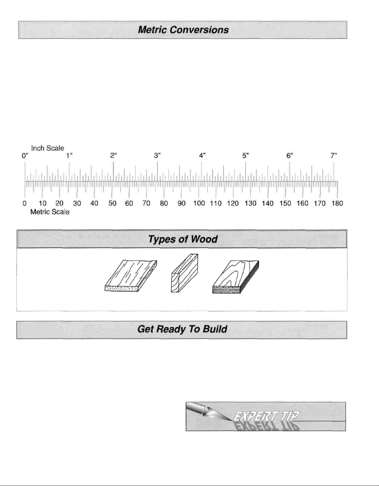
Inches x 25.4 = mm (conversion factor)
1/64" =
1/32" = .8mm
1/16" = 1.6mm
3/32" =
1/8" =
5/32" = 4.0
.4
2.4
3.2
mm
mm
mm
mm
3/16" = 4.8 mm
1/4" = 6.4 mm
3/8" = 9.5
1/2" = 12.7mm
5/8" = 15.9mm
3/4" = 19.0 mm
mm
1" = 25.4mm
2"
= 50.8
3" =
6" = 152.4mm
12" = 304.8mm
18" = 457.2mm
76.2
mm
mm
21" = 533.4mm
24" = 609.6 mm
30" = 762.0mm
36" = 914.4mm
Balsa
D 1. Unroll the plan sheets. Re-roll the plans inside out to
make them lie flat.
D 2. Remove all parts from the box. As you do, figure out
the name of each part by comparing it with the plans and
the parts list included with this kit Using a felt tip or ball
point pen, lightly write the part name or size on each piece
to avoid confusion later Use the die-cut patterns shown on
page 6 to identify the die-cut parts and mark them before
removing them from the sheet Save all leftovers If any of
the die-cut parts are difficult to punch out, do not force
them' Instead, cut around the parts with a hobby knife. After
punching out the die-cut parts, use your T-Bar or sanding
block to lightly sand the edges to remove any die-cutting
irregularities.
Basswood Plywood
D 3. As you identify and mark the parts, separate them into
groups, such as fuse (fuselage), wing, fin, stab
(stabilizer), and hardware.
Zipper top food storage bags are handy to store
your parts as you sort, identify, and separate them into
subassemblies
5
Page 6
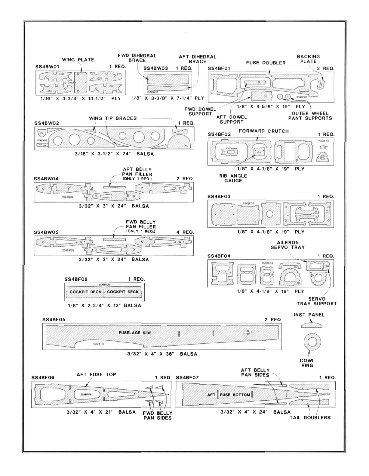
Die-Cut Patterns
6
Page 7
Work over the plans, covered with waxed paper, on a flat
work surface. Refer to the plans to identify the parts and
their locations.
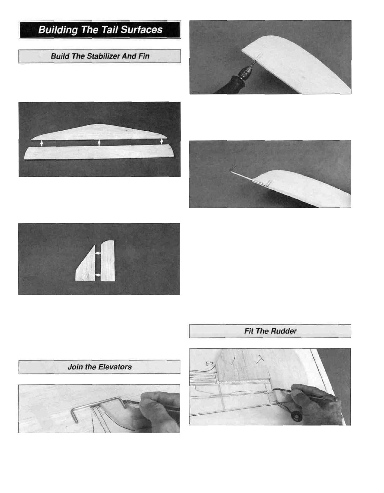
D 1. Locate the shaped 1/4" balsa forward and aft stab
parts. Check their fit and sand the mating edges as
needed. Glue the two parts together with a thin bead of
medium CA. Wipe off any excess from the surface before
it cures.
D 5. Carefully draw a centerline all around the edges of
both elevators. Drill a 1/8" diameter pilot hole into the LE of
each elevator (on the centerline) at the marked location.
Re-drill the holes with a 9/64" bit. The holes must be at
least 1-1/8" deep.
D 6. Cut a 1/8" deep groove in the elevator LE between
the inside edge and the hole you drilled. Insert the joiner
wire. Adjust the depth of the groove until the joiner wire is
flush with the LE.
D 7. Test fit the joiner wire into both elevators. Make sure
that both elevators are flat on the work surface and that the
tips of the elevators align with the tips of the stab.
D 2. Locate the shaped 1/4" balsa forward and aft fin
parts. Check their fit and sand the mating edges as
needed. Glue the two parts together with a thin bead of
medium CA. Wipe off any excess from the surface before it
cures.
D 3. Sand the joints of both assemblies smooth with sharp
220-grit sandpaper and a sanding block.
D 4. Tape the two shaped 1/4" balsa elevators in position
on the TE of the stab. Center the bent elevator joiner wire
over the elevators as shown, then mark the location of
the "arms."
D 8. Sand the LE of the elevators to a "V" shape as shown
on the plans. Sand a radius on the LE and tip ends of the
stab and the TE of the elevator. Leave the TE of the stab
squared off.
D 9. Position the shaped 1/4" balsa rudder over the plans.
Align the bent wire tail gear over the bottom end of the
rudder as shown on the plans. Mark the tail gear "arm"
location on the centerline of the rudder LE. Drill a 7/64"
hole 5/8" deep at this spot.
7
Page 8
D 10 Cut a groove from the tail gear hole to the bottom
end of the rudder that will allow the nylon tail gear bearing
to fit flush with the LE of the rudder
D 11 Carefully draw a centerline all around the edges of
the rudder Sand the LE of the rudder to a "V" shape as
shown on the plans Sand a radius on the LE of the fin and
the TE of the rudder Leave the TE of the fin squared off.
Note: The wing panels are built "UPSIDE-DOWN" on
the plans Since it is the standard convention to show the
Top View of the wing, and the wing panels are built
upside-down, the LEFT wing panel is built over the
RIGHT Wing Top View and vice-versa This does not
present any problems; just be sure to build a left and
a right wing.
D 2 After the epoxy has cured, cut out the appropriate
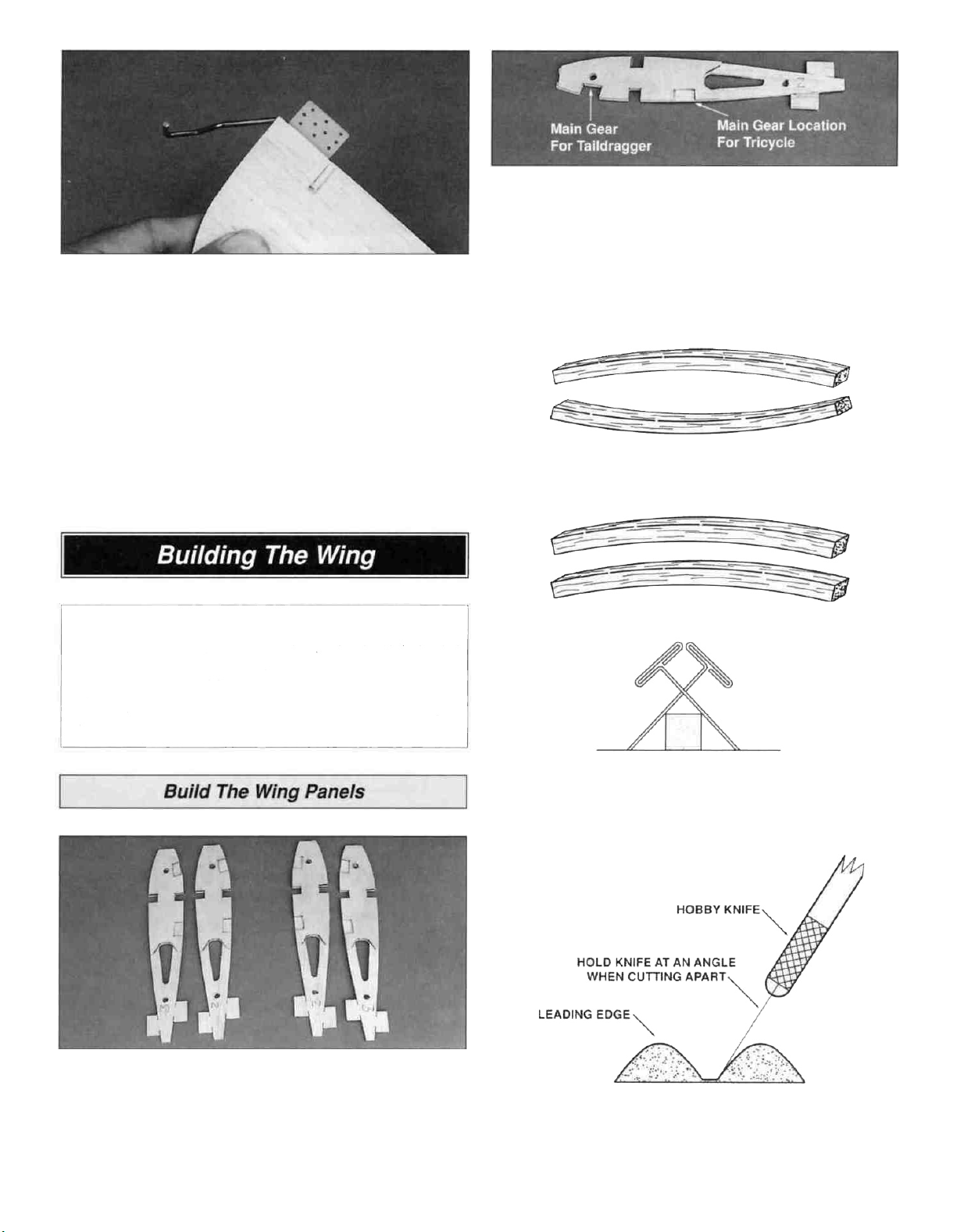
notch in each W-2 and W-3 rib for the landing gear rails If
you are building a taildragger, cut away the balsa from
the front notch. For a tricycle gear configuration, remove
the balsa from the rear notch
TWO WARPED SPARS INSTALLED
THIS WAY WILL RESULT IN A
STRAIGHT WING
TWO WARPED SPARS INSTALLED
THIS WAY WILL RESULT IN A
WARPED WING
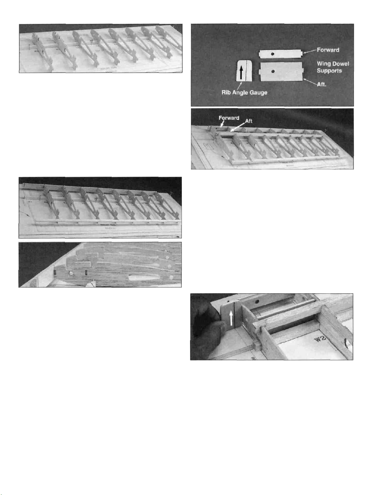
D 1 Lay out 3/32" die-cut wing ribs W-2 and W-3 exactly
as shown in the photo Position the 1/16" die-cut birch ply
doublers (LGD) on each rib as shown By so doing we will
be making a right and a left pair Use 30 minute epoxy to
glue the doublers to the ribs Make sure that the doublers
are perfectly aligned with the ribs spar notches
D D 3 Use the cross-pinning technique to pin a 3/8" x 3/8"
x 25-1/4" balsa spar over a wing plan Don't forget the
waxed paper.
D 4 The shaped and notched wing leading edges (LE)
and trailing edges (TE) are fastened together by thin strips
of balsa Separate them by cutting with a hobby knife, as
shown in the sketch above
8
Page 9
D D 5. Don't use any glue until instructed to do so. As
the wing panels are built upside-down, fit the W-2 and W-3
ribs to the spar with the landing gear notches pointing
upward. Check that the ply doublers are on the correct side
of the ribs as shown on the plans. Add the remaining W-4
ribs all the way to the wing tip. The jig tabs on the
building board should be closer to the TE than the jig
tabs facing upward.
D D 6. Sight down the length of the TE. Check that all ribs
are aligned and have the correct side up.
D D 11. Test fit the forward and aft die-cut 1/8" ply wing
dowel supports in the notches in W-2. The aft wing dowel
support will fit correctly only one way. Wiggle rib W-1 into
position, popping it into the LE and TE notches.
Note: The LE and TE notches need to be widened slightly
to allow for the rib angle. The tabs on the wing dowel
supports fit into the die-cut slots in W-1. Don't glue
anything yet!
D D 7. Fit the notched leading and trailing edges to the
ribs. The LE must be centered vertically on each rib. The
TE should be flush with the top and bottom of the ribs. Align
the ribs over the plans and true everything up. Glue W-2
and the wing tip W-4 rib to the TE, then pin the TE to the
building board to keep the wing flat.
D D 8. Sight down the TE from the wing tip. If the TE is not
straight, insert folded paper strips under the jig tabs of each
low rib until the TE is straight. While holding each rib in
contact with the building board (or paper shims), use thin
CA to glue all remaining ribs to the TE.
D 1-1 9. Repeat this gluing process for the LE. Start with
the two outside ribs, then work toward the center. Make
sure that each rib is pressed firmly onto the spar and is also
aligned with the plans.
D D 10. Glue the ribs to the lower spar, then install and
glue the upper 3/8" x 3/8" x 25-1/4" balsa spar in position.
Be sure to keep the ribs vertical as you do this step.
D D 12. Draw a line through the two index marks on the
die-cut 1/8" ply rib angle gauge. Hold the gauge against
W-1 with the line you drew on the reference line on the
plans. The angle of the rib and wing dowel supports should
match the angle of the gauge. If not, examine your work
and correct any mistakes before gluing the assembly in
place. When satisfied with the fit, use medium CA to glue
the assembly together.
D D 13. Trim and sand the LE, TE, and spars flush with
W-1. Trim only the TE and spars flush with W-4 at the tip.
Leave the LE
long
for
the time
being.
9
Page 10
D D 14. Install 1/16" x 3" x 1-3/8" balsa shear webs on
the aft side of the spars from W-2 to the wing tip. Install
one extra shear web on the forward side of the spars
between ribs W-2 and W-3. Use medium CA and be sure to
get a secure bond. It's not necessary for the webs to be
glued to the ribs.
D D 15. Use a 1/4" drill bit to drill the wing mounting
dowel hole through the LE. The best way to have the holes
line up perfectly is to manually twist the drill bit with your
fingers as shown in the photo. If you have a "Pin Vise" tool,
this would work even better. You can also mark the location
of the hole with a pin pushed through from the inside of the
dowel support, then drill the hole from the LE inward. If you
use the last technique, start with a 3/32" pilot hole, then
slowly enlarge the hole while making adjustments to
the alignment.
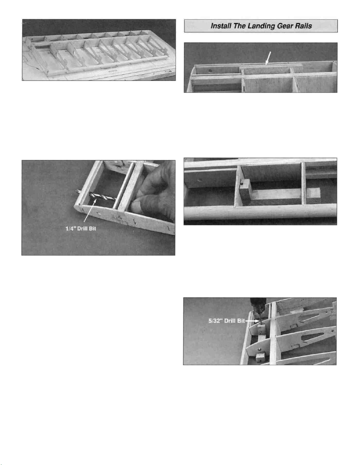
D 1. Test fit the 7/16" x 5/8" x 4" grooved basswood
landing gear rails into the notches on W-2 and W-3. If
necessary, carefully sand the notches to allow a snug fit.
The landing gear rails should protrude above the ribs
by 3/32".
D 2. Use 30-minute epoxy to glue the rails in position.
Epoxy (and clamp for a secure bond) the 7/16" x 5/8" x 3/4"
grooved hardwood landing gear blocks to the inside of the
landing gear rails and also to the ply doubler on W-2. It is
essential that the landing gear blocks be accurately aligned
with the landing gear rail.
D D 16. Round off both ends of the 1/4" x 2-3/4" hardwood
wing dowels (See wing plan) Test fit a dowel (without
gluing) into the LE and aft dowel support. The fit should be
snug, so don't enlarge any of the holes more than
necessary. When satisfied with the fit, remove the wing
dowel and set it aside for later use.
D 17. Repeat steps 3-16 for the other wing panel.
D 3. After the epoxy has fully cured, drill a 5/32" hole
through the landing gear rail working from the top of the
landing gear block, as shown. By drilling in this manner the
block acts as a guide for perfect landing gear alignment.
D 4. Carve a slight radius in the groove of the landing gear
rails at the location of the hole. This radius will permit the
landing gear wire to fully seat in the groove.
10
Page 11
D D 1. Pin a wing panel back on the building board with the
landing gear rail pointing upward. Sight down the TE to
check for straightness-shim the ribs as necessary.
D D 5. Test fit the LE sheet in position. When satisfied with
the fit, press the forward edge of the sheet tightly against
the LE and the ribs, then wick thin CA along the forward
seam. Wipe off any excess CA before it cures. Roll the
sheet into contact with the spar. Working from the center
toward the tip, wick thin CA between the sheet and the
spar.
D D 2. Lightly sand the TE to remove any bumps. Use medium
CA to glue a 3/32" x 7/8" x 25-1/4" balsa TE sheet to the
TE. (Refer to the cross-section on the plans.) Hold a
straightedge across the sheeting while the CA cures to
keep the TE flat and straight.
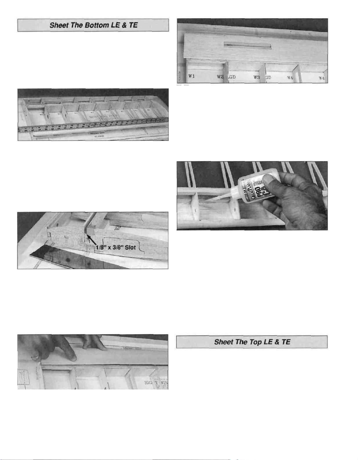
D D 3. Use a razor saw or hobby knife to cut a 1/8" x 3/8"
slot through the W-1 rib between the spar and aft dowel
support as shown in the photo. Do not cut more than 3/8"
down. After the wing is sheeted, we will finish cutting out
the opening for the ply wing joiners.
D D 6. Wick CA around the seam between the sheeting
and the landing gear rail.
D D 7. Lift the wing off the building board. Then, while
holding it flat on your work surface, wick thin CA between
the ribs and the sheet from the inside of the wing. Add a
fillet of medium or thick CA along the inside of the LE.
D 8. Repeat steps 1-7 to sheet the bottom of the other
wing panel.
D D 4. Butt a 3/32" x 2-1/2" x 25-1/4" balsa sheet tightly
against the lip of the LE. Press down on the sheet with your
fingers in the vicinity of the landing gear rail to make an
impression of the landing gear rail on the inside of the
sheet. Turn the LE sheet over, then cut the access hole for
the landing gear rail using the impression mark as a guide.
D D 1. Pin the wing to the building board with the sheeted
side facing down. Trim and sand the jig tabs from the top of
the ribs (the sheeted side.) Sight down the TE to make sure
it's straight. Shim any low ribs.
D D 2. Glue a 3/32" x 7/8" x 25-1/4" balsa sheet to the TE
and ribs as you did with the bottom of the wing panel.
D D 3. Cut a 1/8" x 3/8" slot in W-1 between the spar and
the dowel support as you did in step #3 of the previous
section.
11
Page 12

D D 4. Test fit a 3/32" x 2-1/2" x 25-1/4" balsa sheet along
the LE of the wing panel. Make sure that it fits flush. Wick
thin CA along the LE joint while holding the sheet in
position. Gently lift the aft edge of the sheet and quickly
apply a bead of medium CA to the top of each rib. Press
the sheet into contact with the ribs and hold it there until the
CA cures. Wick thin CA along the joint between the sheet
and the spar. Hold the sheet edge down while the CA cures.
D D 5. Finish cutting the access slots in W-1 for the wing
joiners as shown in the photo. Notice, there is a partially
die-cut line 1/8" behind the forward edge of the spars.
Finish cutting both ends of this line with a hobby knife. This
space is for the wing joiner doubler.
D D 6. At this stage, all remaining jig tabs should be trimmed
off and the rib edges sanded smooth.
D 7. Repeat steps 1-6 to sheet the top of the other
wing panel.
D D 2. Glue the die-cut 3/16" balsa wing tip braces to the
top and bottom of the wing tips at the locations shown on
the plans. Refer to the wing plan, then shape the LE to
blend with the wing tip as shown in the photo.
D D 3. Cut and install cap strips made from six 3/32"
x 1/4" x 24" balsa sticks onto the top and bottom of each
W-4 rib between the LE and TE sheeting. Do not cap the
W-3, W-2, and W-1 ribs as they will be fully sheeted later.
D D 4. Cut one 2" length from each of the two 1-1/8" x 24"
tapered balsa ailerons. Be sure to measure carefully and
make your cuts square. This is where a miter box comes in
handy. Use medium CA to glue both 2" wing tip TE in
position, to the TE'S and wing tips.
D 5. Repeat steps 1 -4 for the other wing panel.
D D 1. Center a die-cut 3/16" balsa wing tip on the
outboard W-4 rib between the spars. The forward edge
must be centered on the LE, and the aft end should align
with the TE. Glue the tip in position at a 90° angle to W-4.
Repeat for the other wing panel.
Note: Before actually using any glue for steps 1 - 4, test fit
the entire assembly to make sure the wing panels fit
properly. Although dihedral angle is not critical, when the
center section is on the building board, both wing tips
should be raised 1".
D 1. Insert 1" of the 1/8" x 2" hardwood alignment dowel
through the hole at the aft end of W-1. Glue it to the inside
of the TE with CA.
12
Page 13

D 2 Coat the exposed aft surface of the ply wing dowel
support with 30-minute epoxy Use a stick or brush to
apply epoxy to the forward edge of both wing spars and the
1/8" x 1-7/16" x 6-1/8" die-cut ply forward dihedral brace
Slide the brace into the slot until it touches W-2
D 3 Completely coat one side of the 1/8" x 5/8 x 6-1/8"
die-cut ply aft dihedral brace with 30-minute epoxy, then
insert it behind (and gluing it to} the forward dihedral brace
Work a little epoxy around the edges to obtain a good bond
with the spars
CA is much harder than balsa, so when you sand edge
glued sheets you will usually end up with a ridge along the
joint To avoid this problem, the Great Planes Model Shop
team has reverted to using wood glue for this application
We prefer Great Planes Wood Glue as it sets quickly, is
water resistant, and sands easily We put a blob of the
glue on a sheet of waxed paper, then apply it to the edge
of the wood with a fingertip After joining the sheets, wipe
off any excess with a tissue, then use a couple of strips of
masking tape to hold the sheets together while the glue
sets
Sand the joint by using a sanding block and 220-grit
sandpaper Work the block in a circular motion across the
joint until smooth
D 4 Working quickly apply 30-minute epoxy to the wing
dowel support and spars of the other wing panel and also
to the mating surfaces of the W-1 ribs Slide the two wing
panels together Glue the 1/8" alignment dowel to the inside
of the second wing panel Make sure the panels are aligned
from LE to TE, then clamp or tape the two panels together.
D 5 Before the wing joining epoxy has cured, work some
30-minute epoxy into both of the dowel holes in the LE
Insert the 1/4" x 2-7/8" hardwood wing dowels through the
LE and into the ply aft dowel support
D 1 Cut eight 6-1/2" long pieces of sheeting from two
3/32" x 3" x 30" balsa sheets Lightly sand off the edges to
remove balsa fuzz Make four center skins by edge gluing
four pairs of the 6-1/2" sheets together.
D D 2 Trim one of the bottom skins to fit between the LE
and TE sheeting from W-1 to W-3 Be sure that the skin
covers only one W-1 rib Glue it in place.
D 3 Repeat step 2 for the other wing panel IMPORTANT:
Be sure to obtain a good glue joint along the wing's
centerline where the sheeting fits together Place a pad of
foam rubber on top of your workbench to protect the bottom
sheeting from hangar rash while you work on the top surface.
13
Page 14

D 4. Refer to the photo above, then use a razor saw or
hobby knife to finish cutting the servo opening in the W-1
ribs. The opening has been partially die-cut.
D 5. Install the die-cut 1/8" ply servo tray support at the
rear of the servo opening. Fit the die-cut 1/8" ply servo tray
into the notch on top of the servo tray support, then press it
into position on top of W-1. The servo tray should be flush
with the top edge of the spar and even with the top edge of
W-1. After you have checked the fit, glue the parts in
position with medium CA.
D 8. Cut and install another skin for the other half of the
wing center section. Cut the other half of the servo opening
as you did in step #6.
D D 1. Position the tapered and grooved 1-1/8" x 2-1/2"
hardwood wing center TE pieces over the plans and mark
the location of the aileron torque rod exits. Cut a notch in
the top forward edge as shown in the photo.
D 6. Trim a 6-1/2" balsa center skin to fit between the LE
and TE from W-1 to W-3. Align the inboard edge of the skin
with the centerline of the wing (between the two W-1 ribs),
then mark and cut "half" of the servo opening. Enlarge the
sheeting opening 1/4" on both ends to allow the servo
grommets to clear the sheeting. Test fit the sheeting
and servo.
LI 7. Glue the sheeting in position with medium CA.
Note: Because the top of the wing is curved and the servo
tray is flat, apply a thick bead of glue to the top of the servo
tray, then allow the skin to curve naturally without
squeezing it into contact with the servo tray. The CA will
provide support for the skin.
D D 2. Hold the wing center TE against the aft edge of the
wing, aligned with the wing's centerline. Mark the torque
rod notches on the top of the wing.
D D 3. Cut shallow notches on the top aft edge of the
wing to allow the torque rod to move freely.
D D 4. Sand the nylon surface of both torque rod tubes
with coarse sandpaper to roughen them up for better
glue adhesion.
14
Page 15

Important: Sand a slight angle on the inboard edge of the
wing center TE to permit the two pieces to fit flush when
matched to the dihedral angle.
D D 5. Lightly coat the torque rods with petroleum jelly,
then slide the nylon tube back and forth a few times to
lubricate the inside of the tube. This procedure will help
prevent the torque rod from being glued to the tube during
the next step.
D D 6. Coat the center portion of the nylon tubes with 30minute epoxy. Then insert the tubes into the grooves of the
wing center TE. Wipe off any epoxy that may squeeze out
with a tissue. Apply epoxy to the forward edges of the wing
center TE, then glue them in position as shown on the
plans. Use masking tape to hold the wing center TE in
position while the epoxy cures.
D 10. While holding an aileron against the inside edge of
the wing center TE, draw a line on it that matches the
inside edge of the wing tip TE. Cut the aileron 1/8" shorter
than the TE opening to allow for covering material.
D 8. Draw a centerline through the two punch marks on the
1/16" die-cut birch ply wing plate. After the wing center TE'S
are completely secure, use 6-minute epoxy to glue the wing
plate in position on the bottom of the wing. Use the
centerline you drew to align the wing plate with the
centerline of the wing. The aft edge of the wing plate must
be flush with the aft edge of the wing center TE. Clamp the
wing plate in position while the epoxy cures.
D 11. Hold the aileron in position, centered in the opening,
then mark the location of the torque rod arms.
D D 12. Drill a 1/8" hole 3/4" deep into the forward edge of
the aileron to accept the torque rod arm.
D 9. Drill two 1/4" holes through the wing center TE using
the holes in the wing plate for the locations.
D D 13. Cut a groove from the hole to the inboard edge of
the aileron to accept the torque rod. Hint: A sharpened
piece of 1/8" brass tubing works well for this task.
15
Page 16

D 14. Draw a centerline on the forward edge of the aileron.
Sand the forward edge of the aileron to a "V." Refer to the
cross section of the wing on the plans for the desired angle.
Well, you are about halfway through the framing stage, so
clean up your workbench, have a soda, and let's build
the fuse.
D 1. Locate both die-cut 3/32" balsa fuse sides. Place the
fuse sides on a flat work surface with the wing saddles
facing toward each other as shown in the photo. Use
medium CA to glue the die-cut 1/8" ply fuse doublers in
position. Note: Be sure that you make a right and left fuse
side. The edges must be flush and the 1/8" x 1" notch at
the forward end of each fuse side exactly match the
doublers notch.
D 4. Glue F-3 and F-4 into the notches of the forward
crutch and the aft fuse top as shown. Use a triangle to hold
all the formers vertical while the CA cures.
D 5. Cut two 1/8" x 1/4" x 3" ply servo tray doublers from
leftover die-cut ply. Glue these doublers as shown above,
to the die-cut 1/8" ply servo tray.
IMPORTANT: Drill a 3/16"dia. hole through the die punch
marks in formers F4 - F6 before assembly. These holes are
for the pushrod tubes. Hint: Lay the part on a piece of
leftover wood when drilling, to prevent break-out.
Note: The formers are stamped only with the necessary
part of their names.
Note: The fuse is built upside-down over the plans. The
plan sheet may be cut apart if space is a problem.
D 2. Cover the bottom view of the fuse plans with
waxed paper.
D 3. Position and pin the die-cut 3/32" balsa aft fuse top
and die-cut 1/8" ply forward crutch over the plans.
Note: All fuse formers must be installed with their
die-stamped numbers facing forward. This is to ensure
correct alignment of the pushrod holes and locking tabs.
D 6. Glue the servo tray into the notches of F-3 and F-4
with the doublers facing down toward the plans.
D 7. Glue F-5, F-6, and F-7 into their notches on the aft
fuse top. Make sure that the die-stamped numbers face
toward the nose of the model.
16
Page 17

D 8. Use 6-minute epoxy to glue F-1B to F-1C and F-2 to
F-2B. Important: F-1B is slightly shorter than F-1C to
allow for the angle of the cowl bottom. The same height
difference applies to F-2B, which is shorter than F-2.
D 11. Fit a fuse side in position. Make sure all of the notches
and tabs are fully seated. Wick thin CA into all joints
between the formers, the forward crutch, and the aft fuse
top. Add a fillet of medium CA to one side of each former
where they touch the fuse sides. Repeat this operation for
the other fuse side.
D 12. Glue the 9/16" x 2" tapered balsa tail wedge between
the fuse sides, flush with the aft edge of the fuse. Use a
triangle between the fuse side and the building board to
check vertical alignment of the tail wedge.
D 13. Remove the lower fuse frame from the building
board and give it a quick once-over with a sanding block
and 150-grit sandpaper.
D 9. Use 6-minute epoxy to glue the F-1 and F-2 assemblies
into the notches on the forward ply crutch.
D 10. Glue the left and right die-cut 3/32" balsa tail
doublers to the aft fuse top and F-7 as shown in the photo.
Do not glue the tail doublers to each other at the
aft end.
D 1. Cut the 36" outer pushrod tube in half to make two
18" tubes. Sand the outside of the tubes with 80-grit
sandpaper to roughen them up.
D 2. Slide the pushrod tubes through the holes in formers
F-4 through F-7, and out through the slots in the fuse sides.
About 1-1/4" of the tubes should be protruding forward of
F-4. Glue the pushrod tubes to all of the formers and to the
inside of the fuse sides with medium CA.
17
Page 18

D 3. With the fuse on a flat surface glue the die-cut 3/32"
balsa aft fuse bottom to the formers and the fuse sides.
D 1. Sand or cut off the two little bumps on the inside
of
F-2.
D 4. Use the F-7 cross-section on the plans to mark
stringer locations. Center the bottom edge of die-cut 1/8"
ply F-7B on the die-cut 3/16" balsa F-7C, then glue it in
position. Draw a line across the aft edge of former F-7 on
the aft fuse top. Align the aft edge of former F-7C with this
line and glue it to the aft fuse top. F-7B faces toward the
nose of the model.
D 5. Use 6-minute epoxy to glue the die-cut 1/8" ply F-1A
to the forward face of F-1B and to the fuse sides. Clamp it
in place while the epoxy cures. Sand the forward edges
of the fuse sides flush with F-1A after the epoxy
has cured.
D 2. Refer to the side view of the plans. Notice that the diecut ply former F-2C is positioned directly over the lower aft
F-2 former and does not use a tab for alignment. Glue it to
the die-cut forward crutch with medium CA.
D 3. Glue die-cut ply formers F-3B, F-4B, F-5B, and F-6B
into their notches on the fuse top. Use a triangle to maintain
vertical alignment.
D 6. Hold the two halves of the die-cut 1/8" balsa cockpit
deck together. If the tabs on both ends don't match
exactly, turn one of the pieces end-for-end. When the
pieces match, edge glue them together to make the full
cockpit deck. Test fit the cockpit deck between F-3B and
F-4B. It will fit correctly only in one direction. Glue it
in place.
D 7. Cut the 3/16" x 3/8" x 18" balsa aft top stringer to fit
flush with the forward face of F-4 and the forward face of
F-7C. Glue the stringer into the top center notches of
the formers.
D 8. Cut and install the 1/8" x 3/8" x 18" balsa side
stringers to fit in the remaining notches from F-4 to F-7C.
Sand the stringer ends flush with F-4.
18
Page 19

D 9. Cut a notch 1/8" x 3/32" in both corners of the die-cut
3/16" balsa F-4C. Center and glue F-4C to F-4B and also to
the forward edge of all aft stringers. Notch 3/32" from the
forward corners of both bottom stringers as shown in the
photo. These notches will provide a recess for the forward
side sheeting.
The Great Planes adjustable engine mount is simple and
convenient to use. It may be used to mount most .40 - .60
two-stroke and .40 - .70 four-stroke engines. Nose gear
bearings are incorporated in the mount and work whether
the mount is horizontal or vertical. The bearing hole is 5/32"
[4 mm] diameter.
D 3. Drill an 11/64" diameter hole at each of the four
die-punch marks on F-1A, then install the mount using four
6-32 x 1" machine screws, #6 flat washers, and
6-32 blind nuts. Tighten the machine screws all the way to
draw the blind nuts into position, then loosen them slightly
to allow the mount to be adjusted to fit the engine. Secure
the blind nuts to the firewall with a drop or two of medium
CA around the flange.
D 1. Cut or break the "spreader bar" from each mount half.
Carefully trim any extra material left by the spreader bar
from each mount half. The surfaces where the spreader
bars were attached must be smooth to allow the mount
halves to fit together. Trim the flashing off any rough edges
if necessary. Assemble the mount halves as shown.
D 2. Draw centerlines on F-1A by connecting the punch
marks on the firewall.
D 4. Slide the engine mount halves apart until the engine
mounting lugs will sit flat on the beams. Adjust the mount
until the firewall centerline is centered between the "tick"
marks on the mount. Tighten the 6-32 screws to hold the
mount firmly in position against the firewall. Position the
engine so that the backplate of a spinner will be 4-15/16" in
front of the firewall. Mark the engine mounting holes on the
mount. Remove the engine and drill a 7/64" hole through
the beams at each mark. Install the engine with the 6-32 x
3/4" sheet metal screws that have been provided with
this kit.
Note: When installing an 0. S. .70 4-stroke engine, you will
need to remove the choke mechanism in order to position
the engine far enough back on the mounting rails to
achieve the 4-15/16" distance from the firewall.
19
Page 20

D 5. Mark the location for the throttle pushrod hole on F-1A.
D 6. Use a long drill bit to drill a 3/16" hole through the
firewall at the throttle hole location you marked in step 5.
Drill through F-2. Insert a 10" length of outer pushrod tube
through these holes, leaving about 1/4" protruding past the
firewall. Glue the pushrod tube in place. Attach a ball link
to the throttle arm on the engine, then use a drop of 6-
minute epoxy to secure the nut in place. Screw a ball link
socket onto a 2-56 x 36" threaded wire pushrod. Cut the
pushrod to reach from the throttle to about 1-1/2" past the
throttle servo opening in the servo tray. Insert the pushrod
through the outer pushrod tube, then attach the ball link
and socket.
Install Optional Nose Gear
(Skip for the standard taildragger)
You will need that are not included:
D 5/32" straight nose gear wire with coils
(Great Planes #GPMQ4262)
D 5/32" adjustable axle
(Great Planes #GPMQ4280)
D 5/32" wheel collar and set screw
(Great Planes #GPMQ4306)
D 5/32" steering arm with collar
(Great Planes #GPMQ4264)
D 15" pushrod tube and .074" wire
(Great Planes #GPMQ3716)
Refer to these photos when performing the following steps
D 1. Slide the 5/32" steering arm with its wheel collar
over the short end of the nose gear wire.
D 2. Insert the nose gear wire into the bottom hole of the
engine mount.
Note: We used a 10 oz. Great Planes tank (#GPMQ4104)
in our prototypes. By using the supplied right-angle fuel
supply tube, the fuel can be routed to the top of the firewall
without the risk of kinking the tube. You may also route the
fuel tube below the forward crutch to make fishing the tubes
a little easier. The choice is yours.
D 7. Temporarily install the fuel tank. It's a lot easier to see
what is happening at this stage of construction. Decide
where you want the fuel and vent tubes to exit the firewall
and mark the locations. Remove the tank and drill two
15/64" (or 7/32") fuel tube holes through the firewall at the
locations you marked. Re-install the tank and connect the
fuel tubes. Check for kinks and rectify any problems
before proceeding.
D 3. Slide a 5/32" wheel collar onto the wire, then push
the wire into the top hole in the engine mount.
D 4. Check that the nose gear spring coils clear the
firewall then tighten the wheel collar and steering arm on
both sides of the engine mount as shown in the photo.
This will lock the nose gear in position.
D 5. Drill a 3/16" hole through the firewall and F-2 that
aligns with the steering arm and the rudder servo.
Important: The steering pushrod must be on the
opposite side of the firewall from the throttle.
D 6. Insert a 15" length of outer pushrod tube through
the holes and glue it in position, flush with the forward
side of F-1A.
D 7. Enlarge the last hole in the steering arm to 5/64"
D 8. Make a bend in the pushrod wire 1/4" from one
end. Insert the unbent end of the pushrod into the outer
tube, then work the bent section into the enlarged hole in
the steering arm. Test the linkage for free movement.
We will cover final installation and servo hookup later
in this manual.
20
Page 21

D 1. Make four 1/16" x 1/4" x 1/2" balsa shims from
leftover. Spot glue these shims to the die-cut 1/16" ply cowl
ring as shown in the above photo. Center a 2-1/2" spinner
backplate over the cowl ring then spot glue it to the shims.
D 2. Slide the cowl ring assembly down the prop shaft and
secure it with the prop nut.
ring and the firewall. The sides overhang the fuse and cowl
bottom about 3/16". Glue the sides in position.
D 6. Cut two 2-3/4" long pieces of 3/8" triangular balsa
from the 9" stick. Glue these pieces to the cowl bottom and
the cowl side as shown on the fuse plan.
D 3. Position the 5/8" x 4" x 10" shaped balsa cowl
bottom on the bottom of the fuse. Sand the forward edge
until it fits flush with the ply spinner ring, then glue it
in position.
D 4. Sand the aft end of the cowl bottom flush with F-2.
D 7. Sand both ends of the 1/2" x 5/8" x 2-1/4" balsa
forward cowl filler to fit between the cowl sides behind the
spinner ring. Glue it in place. Note: The cowl filler may
require a little extra shaping to provide clearance for a 2-
stroke carburetor.
D 8. Carefully cut the shims to remove the spinner
backplate from the cowl ring. Remove the engine, then
sand the cowl ring to remove the shims and glue.
D 5. Sand the forward and aft edges of the two shaped
1/2" balsa cowl sides until they fit evenly between the cowl
D 9. Use a razor plane, whittling knife, and 80-grit
sandpaper to shape the cowl and blend it with the fuse
sides and cowl ring as shown on the plans. Re-install the
engine and spinner, then finish off the sanding of the cowl
ring, tapering it to match the angle of the spinner.
21
Page 22

Skip this step if you are building a taildragger
D 1. If you are going to be installing nose gear, you
should mark the location of the nose gear wire by
inserting an ice pick or sharpened piece of wire through
the bearing holes in the engine mount from the top, out
through the bottom of the cowl. Enlarge the initial hole to
provide clearance for the nose gear wire and spring coil.
grain several times to soften it up before proceeding. Glue
the forward deck sides to the top edge of the fuse. Apply a
bead of glue to the top stringer, formers, and cockpit floor,
then roll the sheet into position. Hold it in place while the
CA cures.
D 6. Trim and sand the top of the forward deck sides and
stringers flush with the tops of the formers.
D 2. Cut the 3/16" x 3/16" x 24" balsa stringer into two
10-1/2" long pieces. Glue the stringers into the notches on
the corners of F-1A, F-2C, and F3-B. The aft end of each
stringer should extend past F-3B by 3/8". They will also
overhang F-1A by 7/8".
D 3. Cut two 3/32" x 1-1/4" x 18" balsa sheets for the
forward deck sides from a 3/32" x 2-1/4" x 18"
balsa sheet.
D 4. Hold a sheet against the fuse side, then mark and cut
the aft edge to fit the notch you made at F-4B. Check that
the outer cockpit floor edges have been sanded to match
the F-3B former.
D 7. Bevel one end of the 3/8" x 3" x 12" balsa forward
deck top block to match the plans at the instrument panel.
Glue the block in position with the aft edge even with the aft
edge of the stringers. Cut off the forward deck top block
and sides about 1-3/4" forward of the firewall.
D 8. Glue the die-cut 1/32" ply instrument panel to the aft
edge of the forward deck top block and to the cockpit floor.
D 9. Use a razor plane and coarse sandpaper to shape the
forward deck top block to match the radius shown on the
cross sections on the plans.
D 5. If the sheet feels too stiff to be curved without splitting,
wet the outside surface with water, then flex it with the
D 10. Use the "eyeball" method to cut and sand the top
portion of the cowl to fit around your engine. Work slowly,
removing only a little material at a time. Test fit the engine
after each adjustment to be sure you don't go too far.
22
Page 23

From this point on, the model will need to be supported
upside-down. You could invest a few dollars in a Robart
Super Stand or cut an old styrofoam ice chest or
cardboard box to fit the fuse. Foam padding in the cradle
will prevent unnecessary hangar rash.
D 1. Use 30-minute epoxy to glue the 3/8" x 3/4" x 1-3/8"
hardwood wing bolt blocks into the notches at F-4. Add
fillets of epoxy all around these blocks, for a secure bond.
D 2. Clean out the wing dowel holes in F-2 with a 1/4" drill
bit. Test fit the wing and adjust the dowel holes if needed
with a round file.
D 4. Tape the wing in position so it can't move. Run a 1/4"
drill bit through the holes in the aft end of the wing to lightly
mark the wing bolt blocks. Do not drill a hole with the 1/4"
bit. Remove the wing and drill a 13/64" (or use a #10 drill
bit) through each of the wing mounting blocks. Angle the
holes as shown on the side view of the fuse plans. Cut
threads in each block with a 1/4"-20 tap. Put a couple of
drops of thin CA on the threads and, after it has fully cured,
run the tap back through the holes to clean up the threads.
Bolt the wing to the fuse with two nylon 1/4"-20 wing bolts
and leave it in place for the next few steps.
D 3. Seat the wing in the wing saddle and visually align it
with the fuse. Pin a string to the tail post, then extend it out
to a wing tip. Put a piece of tape on the string to mark the
intersection of the string and the wing tip. Swing the string
over to the other wing tip and see if the distances are the
same (see diagram). Make slight adjustments to the angle
of the wing until the distance from the tail to the tips
is equal.
D 1. Draw an accurate centerline on the top of the stab,
perpendicular to the TE of the stab. Draw two more lines
parallel to the centerline, 1/8" on each side.
D 2. Center the stab on the stab saddle and pin it in
position. Study the aft end of the structure from 6-10 feet
back. If the stab tips are not equidistant above the wing,
carefully sand the high side of the saddle until the stab
is aligned.
23
Page 24

D 3. Center the stab visually using the centerline you drew
in step #1. Measure the distance from each stab tip to a pin
centered at the nose. Use 30-minute epoxy to glue the stab
in position.
D 4. Position the fin between the lines on the stab, with the
stab TE and fin TE flush, then pin it in place. Check that it's
aligned with the centerline of the fuse with a long
straightedge held against the fin and the fuse top center
stringer. Use thick CA to glue the fin in position while
holding a triangle against it and the stab to maintain
vertical alignment.
D 7. Use thick CA to glue the shaped fin fillets to the stab,
fin, and fuse.
D 8. Glue the 1/4" triangular fin leading edge fairing to the
fin and the top stringer. Sand the top edge of the fairing to
match the concave shape shown on the plans.
D 9. Fit a leftover of 3/32" sheet between the top stringer
as shown in photo for step 8.
Hang in there. Only a few more things to do before you
start covering.
D 5. Locate the two 1/2" x 1" x 4-5/8" tapered fin fillets.
Draw a diagonal line on the top side (that's the side that
slopes) of each part as shown in the photo. Position the
fillet blocks against the aft side of F-7C. Trace the curvature
on the high end of the fillet blocks.
D 6. Cut along the line with a hobby saw to remove the
excess, then use a razor plane and sanding block to round
the fillet to match the curved line on its forward edge.
Note: Before working on the belly pan, we suggest that you
remove the wing from the fuse, then insert a layer of waxed
paper between the F-2 / LE joint and F-4 / TE joint of the
wing. This will help prevent the wing from being accidently
glued to the fuse.
D 1. Hold a flexible ruler across the bottom of the wing,
touching the fuse at both the forward and trailing edges.
Draw lines on both sides of the wing bottom as shown.
24
Page 25

D 2. Glue two die-cut 3/32" balsa forward belly pan sides
together for both sides of the belly pan. Glue these
assemblies to the bottom of the wing, flush with the inside
of the lines you just drew, touching F-2.
D 3. Fit the die-cut 3/32" balsa forward belly pan filler
between the two belly pan sides and the LE of the wing.
The top of the filler piece must be flush with the top edges
of the belly pan sides.
(ACTUAL SIZE)
D 4. Cut a 3/32" x 2" x 15" balsa sheet in half to make two
7-1/2" pieces. Edge glue two 3/32" x 2" x 7-1/2" balsa belly
pan sheets together. Cut 2-1/4" from the 7-1/2" dimension.
Sand a taper across the aft 1" width of the 2-1/4" sheet.
The taper should look like a chisel point.
D 7. Razor plane and sand the aft end of the bottom cowl
block to blend with the belly pan. The shaping should start
at about the location of the firewall. Sand the bottom two
corners to match the radius shown on the cross section of
the plans.
D 8. The remaining piece of belly pan sheeting should
be 5-1/4".
(NOT ACTUAL SIZE)
D 9. Draw a line 2" from one end, across the 4" width.
Sand the sheet to a chisel point, tapering from the line to
one edge.
D 5. Glue the 2-1/4" belly pan sheet to the side pieces,
forward filler, and the wing sheeting.
D 6. Use the lines you drew in step 1 to sand the sheet to
the correct width.
D 10. Glue the two die-cut 3/32" x 5" aft belly pan sides
along the inside edges of the lines drawn on the wing. The
wide end should be touching F-4. Refer to the fuse plans,
then lightly sand the aft belly pan sides to maintain a
straight line from the aft fuse bottom when the sheeting is
applied. Glue the die-cut 3/32" balsa rear filler between the
two sides and the wing.
25
Page 26

D 11. Draw a couple of reference marks on the TE and
the fuse to help locate the wing mounting bolts, then glue
the aft belly pan sheet to the sides, aft filler, and wing
sheeting. Trim the edges to match the fuse lines.
accept the tail gear bearing. Hint: Use a 1/16" bit to drill
several closely spaced holes, then connect the holes using
a hobby knife.
D 3. Temporarily install the bearing and rudder. The
rudder should fit flush with the fin and aft edge of the
fuse. If not, check if the bearing is fully seated or that the
groove in the rudder is deep enough. The bearing won't be
glued in place until after the model is covered.
D 12. Use a pin and the reference marks to locate the wing
bolt heads. Cut a small (1/8" square) opening to see
exactly where you are in relation to the bolt head, then
enlarge the hole in a circular fashion — a little at a time —
until the wing bolts can be removed.
D 13. Sand the aft belly pan to blend with the fuse and the
wing. Remove the wing and clean up the LE and TE of the
belly pan.
D 1. Insert the tail gear "arm" into the hole you made in the
rudder, then hold the rudder up to the fin. Center the rudder
top to bottom.
D 4. While you have the rudder in position mark the
location of the elevator joiner wire on the rudder. Use a
round file or Dremel tool to grind a half-round notch to
provide clearance for the joiner wire.
D D 1. Use a sharp #11 blade in a hobby knife to score
around the cut-lines of the right and left halves of both
wheel pants. By flexing the plastic, the excess material will
break free — if not, carefully repeat the scoring operation,
then try again.
D D 2. Sand the mating surfaces with coarse sandpaper.
D 2. Mark the location of the tail gear bearing on the aft
edge of the fuse. Cut a slot in the center of the tail post to
D D 3. Drill a 5/32" hole through the inside halves of both
pants at the bottom of the groove for the landing gear leg.
26
Page 27

Roughen the inside of the pants around the gear leg hole,
then glue a die-cut
1/8"
ply
backing plate to the inside
of
each grooved half Roughen the inside of the opposite
wheel pant
half
but
don't
glue the
outer
wheel
pant
support in position until final assembly
D D 4 Join the two halves of the wheel pants by holding
them together, then flowing a few drops of thin CA into the
seam. Hold the parts together until the CA cures.
Accelerator will attack the plastic, so avoid using it.
D D 5 Cut out the opening for the wheels on the bottom of
the pants with a sharp hobby knife Round off the inside
edges with a round file or Dremel Moto-Tool" and
sanding drum.
Fuelproofing may be done either before or after covering
D 1. Fuelproof the engine compartment paying special
attention to the firewall K&B paint or 30-minute epoxy is
recommended
D 2 Fuelproof any external exposed wood and the inside
of the fuel tank compartment
SPECIAL NOTE: Do not confuse this procedure with
"checking the C.G." or "balancing the airplane fore and
aft." That very important step will be covered later in
the manual.
Now that you have the basic airframe nearly completed,
this is a good time to balance the airplane laterally
(side-to-side) Here is how to do it
D D 6 The seams should be filled with Automotive body
filler (Bondo) then sanded smooth in preparation for
painting We will cover installation after finishing.
FINISHING
Many surface blemishes on a framed model are caused
by bumps and balsa chips on the work surface This type
of ding" is best repaired by applying a drop or two of
window cleaner or tap water to the blemish, then running a
sealing iron over the spot to expand the wood fibers After
the surface has dried, sand the expanded area smooth
D 1 Temporarily attach the wing and engine (with muffler)
to the fuselage
D 2 With the wing level, lift the model by the engine
propeller shaft and the fin post (this may require two
people). Do this several times.
D 3. If one wing always drops when you lift the model, it
means that side is heavy Balance the airplane by gluing
weight to the other wing tip.
Note: An airplane that has been laterally balanced will
track better in loops and other maneuvers.
The Super Sportster 40 Mk II does not require much
painting to obtain the scheme shown, on the box, as most
of the finish is done with Top Flite MonoKote The only
painting required is for the wheel pants
The technique we will describe here is the how the model
pictured on the box was finished Make sure the structure is
smoothly sanded with 320-grit sandpaper Remove all dust
from the structure with a Top Flite Tack Cloth so the
MonoKote will stick well
D 1 Fill any scuffs, dings, and the forward end of the
pushrod tube exit slots with balsa filler After the filler has
hardened, cut the pushrod tubes flush with the fuse sides,
then sand the entire structure with progressively finer
grades of sandpaper, ending with 320-grit.
Cover the aircraft with MonoKote using the sequence
below Make sure the MonoKote is thoroughly stuck down
to the structure and all of the edges are sealed Use a Top
Flite MonoKote Hot Sock on your covering iron to avoid
scratching the MonoKote.
27
Page 28

MONOKOTING TECHNIQUE
You can practically eliminate MonoKote wrinkles that
sometimes occur when the model is left out in the sun or
in the back of your car by following this technique used in
the Great Planes model shop:
A Cover your sealing iron with a Top Rite Hot Sock and
turn the heat about 3/4 of the way to the high setting.
2. Rudder left and right side
3 Bottom of elevators
4. Top of elevators
5. Stab bottom
6 Stab top
7. Fin left and right side
8. Fuse bottom
B Say we are going to cover the Stab cut a piece of
MonoKote film about 2" larger all around Strip off the
backing and position the film Tack the film down smack
dab in the middle of the Stab.
C. Pull (as in stretch) the film toward the tip, sealing it to
the balsa from the center out to the tip Work out any
wrinkles and air pockets as you proceed with a
combination of circular and back and forth motion.
D Do the same procedure working the opposite
direction from the center.
E Pull and seal diagonally toward the four corners,
always starting from the center The trick is to shrink out
any wrinkles before you seal the film tothe surface.
F. Use a heat gun to heat and stretch the film around
curved surfaces like the stab and rudder tips, while pulling
on the excess material You may need to pull hard to get
out all of the wrinkles, so wear a glove if you need to.
Follow-up the heat gun with your sealing iron to secure
the bond.
The idea behind this approach (which can be applied to
any part of the model) is to pre-stretch the MonoKote as
it's applied, and remove the air pockets that can expand
later which cause the sags and wrinkles
When covering areas that involve sharp junctions, like the
tail section, cut narrow strips (3/8" to 1/2") and apply them
in the corners before covering the major surfaces The
larger pieces of MonoKote will overlap and capture these
smaller pieces This technique also bypasses the need to
cut the MonoKote in these areas after it has been applied
DO NOT, under any circumstances, attempt to cut the
covering material after it has been applied to the fin
and stab, except around the leading and trailing edges
and the tip. Modelers who do this often cut through the
covering and part-way into the balsa stab This can weaken
the stab to the point where it may fail in flight'
1. Tail Junction Strips as described above
9 Fuse sides
10 Fuse top
11. Ends of ailerons
12 Bottom of ailerons
13. Top of ailerons
14. TE surfaces of wing and belly pan
15 Bottom of left wing panel
16 Bottom of right wing panel
17 Sides and bottom of belly pan
18 Top of left wing panel (overlap covering 1/4" at wing LE
and wing centerline)
19 Top of right wing panel (overlap covering 1/4" at the
LEand wing centerline)
Paints used on the prototype:
We used K & B Super Poxy primer and color coat.
Surface Preparation:
Mix equal parts of K & B primer, hardener, and thinner,
then stir the mixture well Spray the wheel pants with a
thin coat of primer Add a second coat of primer to areas
that need it Its best to allow the primer to dry overnight
before sanding Wet sand the primer with 320 and 400 grit
sandpaper using a sanding block where possible Most of
the primer should be sanded off
Color Application:
The wheel pants were sprayed with K & B Super Poxy We
custom mixed the paint to match the Red MonoKote by
adding a little #8116 Yellow to their standard #8113 Red
color Keep a swatch of MonoKote handy to test and
compare the color on a regular basis All paints dry slightly
darker than they appear while wet Spray on the color coat
when satisfied with the match.
28
Page 29

K & B paints are not difficult to use if you have spray
equipment or an airbrush Use equal parts of the mixed
color paint (Part A) and gloss hardener (Part B),then stir
well Use about 1/3rd of the total volume of parts A and B
combined of K & B thinner Remember to use an approved
respirator or mask
We have found that it's much simpler to do all hinging and
control horn installation after the model is covered
Note: Refer to the fuse plan for the hinge making
instructions Cut 15 hinges from the 2" x 9" supplied material
D 1 Install the elevator joiner wire by thoroughly cleaning
the "arms with rubbing alcohol and roughening them with
coarse sandpaper Fill the holes you drilled in the elevators
with 30-minute epoxy then insert the wire arms all the way
in Make sure that both elevators are flat on the work
surface and are straight along the hinge line
D 2 After the epoxy has cured, attach the elevator
assembly to the stab with six hinges using the technique
described in the Expert Tip section following these four
steps After the CA has cured, flex the elevators to check
for free movement
Please read the following instructions and follow them
carefully to obtain the best results These instructions
may be used to effectively install any of the various
brands of CA hinges, a
The most common mistake made by modelers when
installing this type of hinge is not applying a sufficient
amount of glue to fully secure the hinge over its entire
surface area or, the hinge slots are very tight restricting
the flow of CA to the back of the hinges This results in
hinges that are only 'tack glued approximately 1/8" to
1/4" into the hinge slots The following technique has
been developed to help ensure thorough and secure,
gluing
A Cut the hinge slot using a #11 blade in a standard #1
knife handle The CA hinges provided have a thickness
that fits this type of slot very well Trial fit the hinge into
the slot If the hinge does not slide in easily, work the
knife blade back and forth in the slot a few times to
provide more clearance (it is really the back edge of the
blade that does the work here in widening the slot)
D 3 Cut the hinge slots for the rudder and test fit the
rudder to the fin with the tail gear in position When
satisfied with the fit remove the rudder Then use
30-minute epoxy to fasten the tail gear bearing into the
fuse Coat the wire where it passes through the bearing
with petroleum jelly to prevent it from becoming glued to
the bearing
D 4 Pack the tail gear hole in the rudder with epoxy, then
install the rudder in the same way as the elevators, using
three hinges Use a tissue dampened with alcohol to
remove any excess epoxy that squeezes out
The hinge material supplied in this kit consists of
a 3-layer lamination of mylar and polyester It is specially
made for the purpose of hinging model airplane control
surfaces Properly installed this type of hinge provides
the best combination of strength, durability and ease of
installation We trust even our best show models to these
hinges, but it is essential to install them correctly
B Drill a 3/32" hole, 1/2" deep, in the center of the
hinge slot. If you use a Dremel Moto-Tool for this task, it
will result in a cleaner hole than if you use a slower speed
power or hand drill Drilling the hole will twist some of the
wood fibers into the slot, making it difficult to insert the
hinge, so you should re-insert the knife blade working it
back and forth a few times to clean out the slot
C Trial fit the hinges into the slots and temporarily attach
the control surface to verify the fit and operation
D Rather than just making a single slit, it is better to cut
away a narrow rectangle of covering to provide an
adequate opening for the CA glue to wick into the slot
E Insert the hinges and install the control surface Verify
the left right positioning of the control surface and close
up the hinge gap to 1/32" or less It is best to leave a very
slight hinge gap rather than closing it up tight, to help
prevent the CA from wicking along the hinge line Make
sure the control surface will deflect to the recommended
29
Page 30

throws without binding If you have cut your hinge slots
too deep, the hinges may slide in too far, leaving only a
small portion of the hinge in the control surface To avoid
this, you may insert a small pin through the center of
each hinge, before installing This pin will keep the hinge
centered while installing the control surface Remove the
pins before proceeding.
F. Apply 6 drops of thin CA adhesive to both sides of
each hinge, allowing a few seconds between drops for
the CA to wick into the slot Note that the small tunnels"
you created by drilling the 3/32" holes allow the CA to
freely travel in to the entire surface of the hinge,
producing an extremely secure bond
wheel collar into position, then seat the outer wheel pant
support on the axle Work a little 6-minute epoxy onto the
back side of the outer wheel pant support then align the
pant with the wing Press the support into position and hold
it while the epoxy cures
D D 3 Attach the wheel pant to the landing gear leg with a
nylon strap and two #2 x 3/8" sheet metal screws.
Tighten the wheel collars
D 4 Secure the tail wheel to the tail gear with two 3/32"
wheel collars.
D 5 Paint the inside of the cockpit flat black (your option )
Trim and install the instrument panel decal
D D 1 Seat the landing gear in the groove on the bottom
of the wing Secure it with two nylon straps and four
#2 x 3/8" sheet metal screws.
D 6 Trim the canopy with scissors using the embossed cut
lines for reference
D 7 Position the canopy on the fuse as shown on the
plans, then lightly trace its edges on the covering with a ball
point pen Trim about a 1/16" wide strip of covering from
around the line you just traced By removing covering the
canopy will adhere better
D 8 Before installing the canopy you may wish to add a
pilot figure We used a Williams Bros #184 Sportsman"
pilot but the torso needed shortening to fit the canopy
height Use the photo on the side of the box for reference.
D 9 Clean the inside of the canopy with window cleaner
and allow it to dry Use R/C-56 or 6-minute epoxy to glue
the canopy in position After the glue has cured use 1/4"
trim tape to conceal the edges
Note: Do a dry run before gluing the outer wheel pant
supports in position You may need to adjust the "supports"
thickness
D D 2 Refer to the plans to see how the wheels are
installed in the wheel pants Start the sequence by inserting
the landing gear into the wheel pant Then slide on a 5/32"
wheel collar, followed by the wheel Work a second
Note: If you are installing a 4-stroke or heavy engine, you
should wrap a flat battery pack with 1/4" foam rubber and
install it between the servo tray and the cockpit floor (as
shown in the photo for step #5) before mounting the servos
D 1 Mount three servos in the servo tray following the
manufacturer s recommendations Install 'cross" style
horns on all servos, cutting off the unused arms
30
Page 31

D 2. Slide a silicone retainer over the "hex" end of a
nylon clevis. Screw the clevis 14 turns onto the threaded
end of a 36" wire pushrod. Cut the unthreaded end to
shorten the wire to 24". Cut five 1/4" bushings from the
plastic inner pushrod tube provided in the kit. Slide the
bushings on the wire pushrod, spacing them about 3" apart
as shown on the plans. If they are too loose, put a drop of
thin CA on the pushrod wire at each bushing to hold them
in place. Locate the two bushings on both ends so that
they will not exit the pushrod tubes. Trim the backing
plate from a nylon control horn, then clip the clevis to the
outer hole of the horn. Make a second pushrod assembly
exactly the same as the first.
3/32" horn screw holes through the control surface, then
prick a few pin holes into the wood under the horn's
location. Apply a drop or two of thin CA to the pin holes to
strengthen the wood. When cured, screw the horn in place
with two 2-56 machine screws and the backing plate.
Repeat for the other control surface.
The photo shows a 4-Stroke, Taildragger Setup
(Refer to this photo when performing steps 5 thru 11)
D 5. Connect the receiver to the servos, switch, and
battery. Turn on your transmitter and receiver, then center
the elevator and rudder servos. Be sure that the trim levers
are centered.
ALTERNATE SERVO LAYOUT
FOR A 4-STROKE TAILDRAGGER
D 3. Refer to the plans to determine which side the
elevator and rudder pushrods will exit the fuse.
Correct Incorrect
D 6. Center the elevator, then mark the pushrod where it
crosses the outside servo horn hole. Enlarge the servo
horn hole with a 5/64" drill bit.
D 7. Make a 90° bend in the pushrod on your mark then
insert it through the enlarged hole in the servo horn. Secure
it in place with a nylon Faslink".
D 8. Repeat steps 6 and 7 for the rudder.
D 9. Hook up the throttle using a brass quick connector on
the servo horn. Make sure that the servo does not stall at
either end of its travel.
D 10. Wrap your receiver in a plastic bag, then wrap with
foam rubber. Secure the foam with a couple of
rubber bands.
D 11. Route the antenna out of the fuselage side as shown
in the photo at step 5. Anchor the antenna to the top of the
fin or to the tail gear wire with a rubber band. Do not trim
any excess wire from the antenna.
D 4. Insert the pushrods into the tubes in the fuse, then
hold a horn in position on either the elevator or rudder (see
sketch above for correct alignment). The pushrod should
not be bent and should slide easily in the tube. Mark the
location for the horn screws on the control surface. Drill the
D 12. Mount the receiver switch and charging Jack through
the fuselage on the side of the fuse opposite to the muffler
exhaust. We suggest using a Great Planes
Switch/Charging jack mount (GPMM #1000) because of
its ease of installation and tidy appearance.
31
Page 32

D 13. Install the aileron servo as shown using two 6" wire
pushrods, swivel clevises, and Faslinks. We suggest
that the swivels be screwed 1/4" below the top edge of the
aileron torque rod arms to start with. Lowering the swivels
will
cause
the
ailerons
to
deflect
more
if
you
need
more throw.
4-CHANNEL RADIO SETUP
(STANDARD MODE 2)
ELEVATOR MOVES UP
RIGHT AILERON MOVES UP
LEFT AILERON MOVES DOWN
Note: The balance and surface throws for this aircraft
have been extensively tested. We are confident that
they represent the settings at which the Super
Sportster 40 Mk II flies best. Please set up your aircraft
to the specifications listed above. If, after a few flights,
you would like to adjust the throws to suit your tastes,
that's fine. Too much throw can force the plane into a
stall, so remember, "more is not better"
Note: This section is VERY important and must NOT be
omitted! A model that is not properly balanced will be
unstable and possibly unflyable.
RUDDER MOVES RIGHT
NOSE WHEEL TURNS RIGHT
CARBURETOR WIDE OPEN
D 14. Turn on the radio system and check the direction of
all control functions. They must all move in the direction
shown in the sketch. If not, change the position of the
reversing switches on your transmitter.
We recommend the following control surface throws:
Note: Throws are measured at the widest part of the elevators, rudder,
and ailerons. Adjust the position of the pushrods at the control/servo
horns to control the amount of throw.
ELEVATOR:
(High Rate)
1/2"
up
5/8" down
RUDDER:
1-3/8" right
1-3/8" left
AILERONS:
(High Rate)
5/16" up
5/16" down
Note: If your radio does not have "dual rates," then set up the control
surfaces to move between the high rate and low rate throws.
(Low Rate)
5/16" up
3/8" down
(Low Rate)
3/16" up
3/16" down
D 1. Accurately mark the balance point on the top of the
wing on both sides of the fuselage. The balance point is
shown on the plan (CG), and is located 3-1/4" back from
the leading edge as shown in the sketch and on the plans.
Hint: Use the full-size wing plan to help you accurately
locate the proper balance point on the wing. This is the
balance point at which your model should balance for your
first flights. Later, you may wish to experiment by shifting
the balance up to 1/4" forward or back to change the
flying characteristics. Moving the balance forward may
improve the smoothness and arrow-like tracking, but it may
then require more speed for takeoff and make it more
difficult to slow down for landing. Moving the balance aft
makes the model more agile with a lighter and snappier
"feel" and often improves knife-edge capabilities. In any
case, please start at the location we recommend and do
not at any time balance your model outside the
recommended range.
D 2. With the wing attached to the fuselage, all parts of the
model installed (ready to fly) and an empty fuel tank, hold
the model upside-down with the stabilizer level.
D 3. Lift the model at the balance point. If the tail drops
when you lift, the model is "tail heavy" and you must add
weight* to the nose to balance. If the nose drops, it is "nose
heavy" and you must add weight* to the tail to balance.
Note: Nose weight may be easily installed by using a
"Spinner Weight" or gluing lead weights into the engine
compartment. Tail weight may be added by using Great
Planes (GPMQ4485) "stick-on" lead weights, and, later, if
the balance proves to be OK, you can open the fuse bottom
and glue these in permanently.
32
Page 33

* If possible, first attempt to balance the model by changing
the position of the receiver battery and receiver If you are
unable to obtain good balance by doing so, then it will be
necessary to add weight to the nose or tail to achieve the
proper balance point.
Charge the batteries
Follow the battery charging procedures in your radio
instruction manual You should always charge your
transmitter and receiver batteries the night before you go
flying, and at other times as recommended by the radio
manufacturer.
Find a safe place to fly
The best place to fly your R/C model is an AMA (Academy
of Model Aeronautics) chartered club field Ask your hobby
shop dealer if there is such a club in your area and join
Club fields are set up for R/C flying and that makes your
outing safer and more enjoyable The AMA also can tell you
the name of a club in your area We recommend that you
join AMA and a local club so you can have a safe place to
fly and have insurance to cover you in case of a flying
accident (The AMA address is listed on page 2 of this
instruction book).
Repeat this test with the engine running at various
speeds with an assistant holding the model It the control
surfaces are not always acting correctly, do not fly! Find
and correct the problem first.
Engine safety precautions
Note: Failure to follow these safety precautions may
result in severe injury to yourself and others.
Keep all engine fuel in a safe place, away from high heat,
sparks or flames, as fuel is very flammable Do not smoke
near the engine or fuel, and remember that the engine
exhaust gives off a great deal of deadly carbon monoxide.
Therefore do not run the engine in a closed room or
garage
Get help from an experienced pilot when learning to
operate engines
Use safety glasses when starting or running engines.
If a club and its flying site are not available, you need to
find a large grassy area at least 6 miles away from any
other R/C radio operation, like R/C boats and R/C cars and
away from houses, buildings and streets A schoolyard may
look inviting but it is too close to people, power lines and
possible radio interference.
Ground check the model
If you are not thoroughly familiar with the operation of
R/C models, ask an experienced modeler to check to see
that you have the radio installed correctly and that all the
control surfaces do what they are supposed to The engine
operation also must be checked and the engine "broken-in"
on the ground by running the engine for at least two tanks
of fuel Follow the engine manufacturer's recommendations
for break-in. Check to make sure all screws remain tight,
that the hinges are secure and that the prop is on tight
Range check your radio
Wherever you do fly, you need to check the operation of the
radio before every time you fly This means with the
transmitter antenna collapsed and the receiver and
transmitter on, you should be able to walk at least 100 feet
away from the model and still have control Have someone
help you Have them stand by your model and, while you
work the controls, tell you what the various control surfaces
are doing.
Do not run the engine in an area of loose gravel or sand, as
the propeller may throw such material in your face or eyes.
Keep your face and body as well as all spectators away
from the plane of rotation of the propeller as you start and
run the engine.
Keep items such as these away from the prop' loose
clothing, shirt sleeves, ties, scarfs, long hair or loose
objects (pencils, screw drivers) that may fall out of shirt or
jacket pockets into the prop.
Use a "chicken stick" device or electric starter, follow
instructions supplied with the starter or stick Make certain
the glow plug clip or connector is secure so that it will not
pop off or otherwise get into the running propeller.
Make all engine adjustments from behind the rotating
propeller.
The engine gets hot! Do not touch it during or after
operation Make sure fuel lines are in good condition so fuel
will not leak onto a hot engine causing a fire.
To stop the engine, cut off the fuel supply by closing off the
fuel line or follow the engine manufacturer's
recommendations Do not use hands, fingers or any body
part to try to stop the engine Do not throw anything into the
prop of a running engine.
33
Page 34

Read and abide by the following Academy of Model
Aeronautics Official Safety Code
General
1 I will not fly my model aircraft in sanctioned events air
shows, or model flying demonstrations until it has been
proven to be airworthy by having been previously
successfully flight tested
highly maneuverable Compared to other sport planes, its
flight characteristics are quite docile and forgiving It does
not however have the self recovery characteristics of a
primary R/C trainer therefore you must either have
mastered the basics of R/C flying or obtained the
assistance of a competent R/C pilot to help you with your
first flights
2 I will not fly my model aircraft higher than approximately
400 feet within 3 miles of an airport without notifying the
airport operator I will give right of way to and avoid flying
in the proximity of full scale aircraft Where necessary, an
observer shall be used to supervise flying to avoid having
models fly in the proximity of full scale aircraft
3 Where established I will abide by the safety rules for the
flying site I use and I will not willfully and deliberately fly my
models in a careless reckless and/or dangerous manner
4 I will not fly my model unless it is identified with my name
and address or AMA number, on or in the model
5 I will not operate models with pyrotechnics (any device
that explodes, burns, or propels a projectile of any kind)
Radio control
1 I will have completed a successful radio equipment
ground check before the first flight of a new or repaired
model
2. I will not fly my model aircraft in the presence of
spectators until I become a qualified flier, unless assisted
by an experienced helper
Balance your propellers carefully before flying An
unbalanced prop is the single most significant cause of
damaging vibration Not only will engine mounting screws
and bolts vibrate out possibly with disastrous effect, but
vibration will also damage your radio receiver and battery
Vibration will cause your fuel to foam, which will, in turn,
cause your engine to run rough or quit
We use a Top Flite Precision Magnetic Prop Balancer
(#TOPQ5700) in the workshop and keep a Great Planes
Fingertip Balancer (#GPMQ5000) in our flight box.
3 I will perform my initial turn after takeoff away from the pit
or spectator areas and I will not thereafter fly over pit or
spectator areas, unless beyond my control
4 I will operate my model using only radio control
frequencies currently allowed by the Federal
Communications Commission
The Great Planes Super Sportster Mk II is a great flying
sport airplane that flies smoothly and predictably, yet is
If you have dual rates on your transmitter set the switches
to high rate for takeoff especially when taking off in a
crosswind Although this model has good low speed
characteristics you should always build up as much speed
as your runway will permit before lifting off as this will give
you a safety margin in case of a flame out When you first
advance the throttle and the tail begins to lift the plane will
start to turn left (a characteristic of all taildraggers ) Be
ready for this and correct by applying sufficient right rudder
to hold it straight down the runway The left turning
tendency will go away as soon as the tail is up and the
plane picks up speed Be sure to allow the tail to come up.
Depending on the surface you are flying from you will need
to apply very little to no up elevator until flying speed is
obtained Don t hold the tail on the ground with too much up
elevator as the Sportster will become airborne prematurely
and will possibly stall When the plane has sufficient flying
speed lift off by smoothly applying up elevator (don't "jerk"
it off to a steep climb1), and climb out gradually
34
Page 35

CAUTION (THIS APPLIES TO ALL R/C AIRPLANES) If, while
flying, you notice any unusual sounds, such as a low-pitched
"buzz," this may be an indication of control surface "flutter"
Because flutter can quickly destroy components of your
airplane any time you detect flutter you must immediately cut
the throttle and land the airplane' Check all servo grommets for
deterioration (this will indicate which surface fluttered), and
make sure all pushrod linkages are slop-free If it fluttered once,
it probably will flutter again under similar circumstances unless
you can eliminate the slop or flexing in the linkages Here are
some things which can result in flutter Excessive hinge gap,
Not mounting control horns solidly, Sloppy fit of clevis pin in
horn, Elasticity present in flexible plastic pushrods Side play of
pushrod in guide tube caused by tight bends, Sloppy fit of
pushrod wire in servo arm, Insufficient glue used when gluing in
the elevator joiner wire or aileron torque rod, Excessive flexing
of aileron, caused by using too soft balsa aileron, Excessive
"play" or "backlash" in servo gears, and insecure servo
mounting
We recommend that you take it easy with your Sportster for
the first several flights, gradually "getting acquainted" with
this classic sport plane as your engine gets fully broken-in
Add and practice one maneuver at a time, learning how she
behaves in each For ultra-smooth flying and normal
maneuvers, we recommend using the "low rate' settings as
listed on page 32 "High rate" elevator may be required for
crisp snap rolls and spins Speed is the key to good knifeedge performance
loading and shoulder-mounted wing with symmetrical airfoil
increase maneuverability CAD engineering and
interlocking, all-wood parts make it easy to assemble.
Requires a 2-stroke .35-.46 or 4-stroke .48-.60 engine and
4-channel radio.
PIPER J-3CUB..................................................GPMA0160
Created from drawings of the original aircraft, Great Planes'
Cub kit takes advantage of today's finest engineering,
including state-of-the-art interlocking construction Nearly
all the wood parts are balsa for easy finishing—and
numerous scale details provide irresistible realism The kit
can be built with a 76 5" span or clipped 61 5" span wing.
Required are a 2-stroke 40-.60 or 4-stroke 48- 80 engine
and a 4-channel radio.
When it's time to land, fly a normal landing pattern and
approach Keep a few clicks of power on until you are over
the runway threshold For your first landings, plan to land
slightly faster than stall speed and on the main wheels, as
this is the easiest way to land your Sportster Later, with a
little technique, you will find you can make slow, 3-point
landings
Have a ball! But always stay in control and fly in a safe
manner.
EASY SPORT" 40..............................................GPMA0150
The 59 2" span Easy Sport 40 lets you move up from
trainers with confidence While it has the ideal proportions
for easy, trainer-like low-speed flight, the model s light wing
F-15EAGLE.......................................................GPMA0438
Any pilot who's mastered a trainer can build and fly this 47"
span, jet-like sport model Its Auto-Lock'" construction
simplifies assembly, and two degrees of wing washout
provide reassuring flight stability But the F-15 is virtually
indistinguishable from a powerful dueled fan jet in the air'
Requires a 2-stroke 40-.50 engine and 4-channel radio
with 4 servos.
35
Page 36

TWO VIEW
Photocopy this drawing and use the copies to design your trim scheme.
 Loading...