

Page 1
INSTRUCTION BOOK
PLEASE READ THROUGH THIS INSTRUCTION BOOKLET IN ITS ENTIRETY BEFORE BEGINNING
ASSEMBLY. IT CONTAINS IMPORTANT INSTRUCTIONS AND WARNINGS CONCERNING THE ASSEMBLY
AND USE OF THIS MODEL.
WARNING! THIS IS NOT A TOY!
This R/C kit and the model you will build is not a toy! It is capable of serious bodily
harm and property damage. IT IS YOUR RESPONSIBILITY AND YOURS ALONE - to
build this kit correctly, properly install all R/C components and flying gear (engine, tank,
pushrods, etc.) and to test the model and fly it only with experienced, competent help, using
common sense and in accordance with all safety standards as set down in the Academy of Model
Aeronautics Safety Code. It is suggested that you join the AMA to become properly insured
before you attempt to fly this model. IF YOU ARE JUST STARTING R/C MODELING,
CONSULT YOUR LOCAL HOBBY SHOP OR WRITE TO THE ACADEMY OF MODEL
AERONAUTICS TO FIND AN EXPERIENCED INSTRUCTOR IN YOUR AREA.
Academy of Model Aeronautics
5151 East Memorial Drive
Muncie, IN 47302-9252 (800) 435-9262 DE40P03
Page 2

TABLE OF CONTENTS
INTRODUCTION
Precautions
Abbreviations
Die Patterns
Decisions You Must Make Now
Other Items Required
Supplies and
Types of
Hardware Drawings
Get Ready to Build
TAIL FEATHERS .................. 6
Build the Rudder
Build the Fin
Build the Stabilizer
Build the Elevators
Install the Hinges
WING ASSEMBLY ................. 9
Build the Wing Panels
Join the Wing Panels
Install Center Ribs and Sheeting
Install Aileron Torque Rods
Fiberglass the Center
Install Wing Tips
Install Ailerons
Temporarily Install Wing Dowels
Install Wing Bolt Plate
Install Wing Strut Plates ............... 16
FUSELAGE ASSEMBLY ............ 17
Prepare Fuse Sides
Assemble Lower Fuselage
Assemble Upper Fuselage
Mount the Wing to the Fuse
Mount Stabilizer and Fin
FINAL ASSEMBLY
Engine Installation
........................
........................
Tools
Wood
.......................
..................
.......................
.........
.................
Needed
.....................
..................
...................
....................
..................
...................
....................
.................
Section
....................
......................
...................
...................
............
................
.........
............
...........
.......
................
.............
.............
............
..............
................
3
3
3
4
5
5
5
6
6
6
6
7
8
8
9
9
12
13
13
14
15
15
16
16
17
17
20
23
24
25
25
Install
"2-cycle
Drill Engine Mount
Install
Servos,
Control Surface Throws
Fitting Fuel Tank, Fuelproofing
Install
Wing Strut Straps
Install Receiver, Switch and Battery ..... 30
Install Main Landing Gear
Install Wheel Pants
Fit Cowl
FINISHING ....................... 33
Additional Fuelproofing
Balance
Final Sanding
Covering
Apply Decals and Trim
Glue the hinges
Install Windshield
Wing Seating
Install Wing Struts ................... 36
Install
Balance Your Model
Final Hookups and Checks
PRE-FLIGHT
Charge the Batteries
Find a Safe Place to Fly
Ground Check the Model
Range Check Your Radio
Engine Safety Precautions
AMA Safety Code .................. 39
FLYING .......................... 40
Caution
NOTES ........................... 41
PARTS LIST ...................... 42
3-View Drawing .................... 44
...........................
the
..........................
Side
...........................
firewall"
Horns and Pushrods
..................
Airplane Laterally
.......................
.....................
...................
.......................
Windows
.....................
.............
..................
......
...............
.........
..............
.............
...............
..........
...............
.................
.................
.............
..................
...............
..............
..............
.............
25
26
26
29
29
30
30
31
32
33
33
33
33
34
35
35
36
37
37
38
38
38
38
39
39
39
40
Please inspect all parts carefully before starting to build! If any parts are missing, broken
or defective, or if you have any questions about building or flying this airplane, please call us at (217)
367-2069 and we'll be glad to help. If you are calling for replacement parts, please look up the part
numbers and the kit identification number (stamped on the end of the carton) and have them ready
when calling.
2
Page 3

INTRODUCTION
3. You must use a proper R/C radio that is in first class
condition, the correct sized engine and correct components
(fuel tank, wheels, etc.) throughout your building process.
Congratulations! Thank you for purchasing the Great
Planes Super Decathlon 40!
The Super Decathlon 40 is a 1/6-scale model of a fullsize Bellanca Super Decathlon, owned by Pete Myers, located at Howell Airport in New Lenox, IL. The airplane was
built by Champion Aircraft in 1979. Pete calls his Super
Decathlon "experimental" because he has made a few
changes to enhance its acrobatic capabilities, the most noticeable of which are the squared-off "clipped" wing tips. The
normal wingspan would be 32'; but, due to the special tips,
Pete's Decathlon spans only 30.5'. You will notice that the
model's wingspan has been increased by 5% to enhance the
flying qualities.
If you are interested in sport scale competition, you'll be
happy to know that color photos of Pete's full-size Super
Decathlon are available from Scale Model Research, 2334
Ticonderoga Way, Costa Mesa, CA 92626.
The Super Decathlon 40 is easy to build and fly, predictable, highly acrobatic, and has no "bad habits," making it a
great sport-scale airplane (as long as you don't get carried
away with the glue bottle and make it a "lead sled")!
Although the model is sufficiently close to scale that it can
place well in sport-scale competition, traditional Great
Planes quality and ruggedness is evident throughout, making
this an airplane you'll want to take along every time you go
to the flying field.
4. You must properly install all R/C and other components so that the model operates properly on the ground and
in the
air.
5. You must test the operation of the model before the
first and each successive flight to insure that all equipment is
operating, and you must make certain that the model has
remained structurally sound. Be sure to check the nylon
clevises often, and replace if they show signs of wear.
6. You must fly the model only with the competent
help of a well experienced R/C pilot if you are not already an
experienced and knowledgeable R/C pilot at this lime.
Note: We, as the kit manufacturer, can provide you with
a top quality kit and great instructions, but ultimately the
quality and flyability of your finished model depends on
how you build it; therefore, we cannot in any way
guarantee the performance of your completed model, and
no representations arc expressed or implied as to the
performance or safety of your completed model.
Remember: Take your time and follow directions to
end up with a well-built model that is straight and
true.
This is not a beginner's airplane! While the Super
Decathlon 40 is easy to build and flies great, we must
discourage you from selecting this kit as your first R/C
airplane. It is fast, highly maneuverable, and lacks the selfrecovery characteristics of a good basic trainer such as the
Great Planes PT Series airplanes. On the other hand, if you
have already learned the basics of R/C flying and you are able
to safely handle an "aileron trainer" airplane such as the
Great Planes Trainer Series or Big Stick Series airplanes,
the Super Decathlon 40 is an excellent choice.
PRECAUTIONS
1. You must build the plane according to the plans
and instructions. Do not alter or modify the model, as doing
so may result in an unsafe or unflyable-model. In a few cases
the plans and instructions may differ slightly from the photos.
In those instances you should assume the plans and written
instructions are correct
2. You must take time to build straight, true and strong.
COMMON ABBREVIATIONS USED IN
THIS BOOK AND ON THE PLANS:
Elev = Elevator
Fuse = Fuselage
LE = Leading Edge (front)
LG = Landing Gear
Lt = Left
Ply = Plywood
Rt = Right
Stab = Stabilizer
TE = Trailing Edge (rear)
" = Inches
INSTRUCTIONS IN BOXES LIKE THIS
ARE VERY IMPORTANT AND SHOULD
BE FOLLOWED CAREFULLY
3
Page 4

DIE PATTERNS
Use this drawing to help you identify the die cut parts
4
Page 5

DECISIONS YOU MUST MAKE NOW
ENGINE AND MOUNT SELECTION
The recommended engine size range is as follows:
.40* - .46 cubic inch displacement 2-cycle
.48 - .70 cubic inch displacement 4-cycle
*NOTE: Performance may be marginal if a non-schneurleported .40 cu.in. 2-Cycle engine is used.
NOTE: If you install a 2-Cycle engine, we recommend
using a muffler that can be completely enclosed inside
the cowl. The muffler shown in the instruction book
photos is a Tatone #11434 Pitts Style Muffler for .45 - .80
engines.
The engine you select will determine how you build the
fuselage, so it is important that you have the engine close at
hand while building.
This kit includes a Great Planes MM40 engine mount
that fits most .40 - .45 (2-Cycle) engines (only slight modification of this mount is required to mount the OS40SF and
OS45SF). If you are installing an OS48 SURPASS (4-cycle),
you may purchase a Great Planes MM60 mount. If you are
planning to install the OS70 SURPASS (4-cycle), you may
purchase the Great Planes MM60L mount. If you prefer, you
may purchase a custom engine mount for your engine, or you
may choose to install shock-absorbing rubber-cushioned
mounts.
NOTE:
with a 4-cycle engine, keep in mind that the RPM of your
engine will be considerably less than that of a 2-Cycle
engine; therefore, you should select a higher pitch
propeller to keep the speed and overall performance
roughly equivalent to that of a 2-Cycle engine. For
example, a 10x6 or 10x7 prop would be used with a .40
(2-Cycle) engine; but a 12x8,11x9 or 10x10 prop may be
the best choices for a 4-cycle engine.
If you
choose to power your Super Decathlon 40
SELECTION OF WHEELS
For maximum scale realism, 2-1/4" diameter main
wheels and a 1" diameter tail wheel may be used. However,
for better handling, we recommend 2-1/2" main wheels and a
1-1/8" or 1-1/4" tail wheel. For operation from a rough grass
field, leave the wheel pants off and use 2-3/4" or 3" main
wheels. To save weight, we recommend using lightweight
foam rubber wheels.
OTHER ITEMS REQUIRED
Four-channel radio with 4 servos
Propellers (see engine instructions for recommended size)
Spinner (2-1/4" diameter)
Fuel Tank (10 or 12 ounce)
SUPPLIES AND TOOLS NEEDED
2 oz. Thin CA Adhesive
2 oz. Medium or Thick CA Adhesive
2.5 oz. 5-Minute Epoxy
2.5 oz. 30-Minute Epoxy
Hand or Electric Drill
Sealing Iron
Heat Gun
Drill Bits: 1/16", 5/64", 3/32", 7/64", 1/8", 9/64", 5/32".
11/64". 3/16", 13/64". 7/32", and 1/4"
Hobby Saw (Xacto Razor Saw)
Xacto Knife. #11 Blades
Pliers
Screw Drivers
T-Pins
3/32" Wheel Collars - 2
Iron-on Covering Material (red & white for scale)
1/16" and 1/8" Striping Tape (blue for scale)
Silicone Fuel Tubing
Wing Seating Tape (or silicone sealer... see instructions)
Latex Foam Rubber Padding (1/4" thick)
Dubro "E-Z Connector" (optional)
Straightedge
Masking Tape
Sandpaper (coarse, medium, fine grit)*
T-Bar Sanding Block (or similar)
Waxed Paper
Lightweight Balsa Filler
1/4-20 Tap, Tap Wrench
Vaseline Petroleum Jelly
Isopropyi Rubbing Alcohol (70%)
Dremel Moto Tool or similar (optional)
*NOTE: On our workbench, we have four 11" T-Bar
sanders, equipped with #50, #80, #100 and #150-grit
sandpaper. This setup is all that is required for almost
any sanding task. We also keep some #320-grit wet-ordry sandpaper handy for finish sanding before covering.
5
Page 6
TYPES OF WOOD
BALSA BASSWOOD PLYWOOD
HARDWARE DRAWINGS,
GET READY TO BUILD
1. Unroll the plan sheets. Re-roll the plans inside out to
make them lie flat.
2. Remove all parts from the box. As you do, figure out the
name of each part by comparing it with the plans and the parts
list at the back of this book. Using a felt tip pen, write the part
name or size on each piece to avoid confusion later. Use the
die-cut patterns on page 4 to identify the die-cut parts and
mark them before punching out. Save all scraps. If any of the
die-cut parts are difficult to punch out, do not force them!
Instead, first cut around the parts with an Xacto knife. After
punching out the die-cut parts, use your T-Bar or sanding
block to lightly sand the edges to remove any die-cutting irregularities.
3. As you identify and mark the parts, separate them into
groups, such as fuse (fuselage), wing, fin and stab (stabilizer), and hardware.
"TAIL FEATHERS"
BUILD THE RUDDER
To build the rudder you'll need the following:
1/4" x 3/4" x 36" balsa sticks
1/4" x 1/2" x 30" balsa sticks
1/4" shaped balsa rudder bottom
D 1. Tape the fuselage plan down to your flat work
surface. Tape a piece of waxed paper over the fin and rudder
portion of the plan.
NOTICE:
The screws supplied in this kit may be "slottedhead" or "phillips-head" screws. The screw types may
differ from those shown on the plans and instructions, but
they are interchangeable.
D 2. Using a razor saw, cut pieces of 1/4" x 3/4" and 1/4"
x 1/2" balsa (from the 36" and 30" sticks) to make the rudder
framework. Working right on the plan, glue together these
pieces and the rudder bottom, using thin CA glue.
6
Page 7
D 3. From the 1/4" x 1/2" x 30" sticks, cut "braces" to fit
between the rudder framework, and glue them in place.
NOTE: It is not necessary to get these braces in the exact
position shown on the plan.
D 4. Examine the rudder framework and add thick CA
glue to any open
sandpaper to sand both sides of the rudder framework smooth.
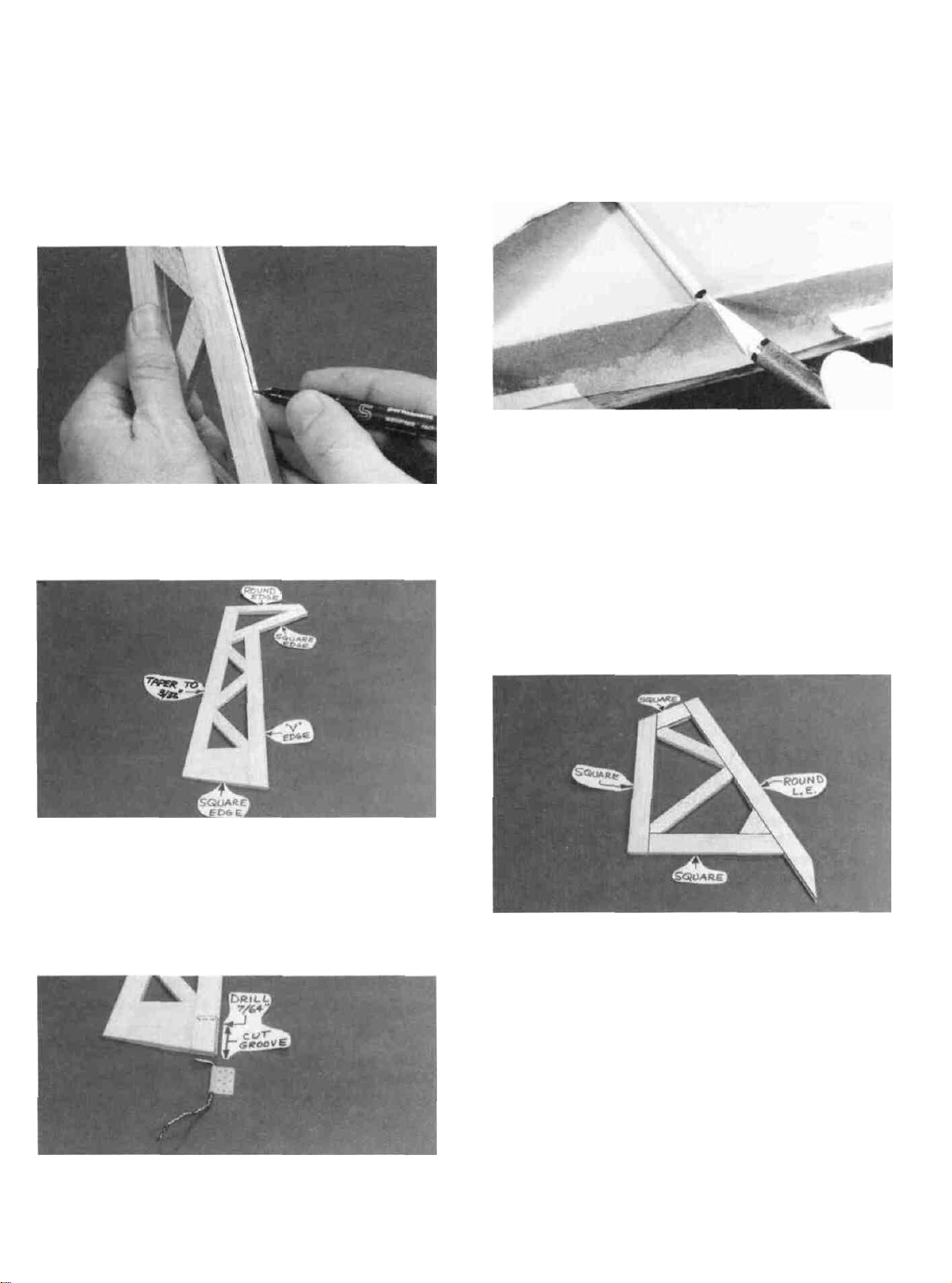
D 5. Carefully draw a centerline all around the edges of
the rudder (this will help to maintain symmetry when sanding).
joints,
then use
your T-bar
with
medium grit
hole is drilled slightly oversize to allow for positioning, and
to create a hard epoxy "sleeve" around the wire). Then
groove the rudder leading edge to accept the tailgear wire .
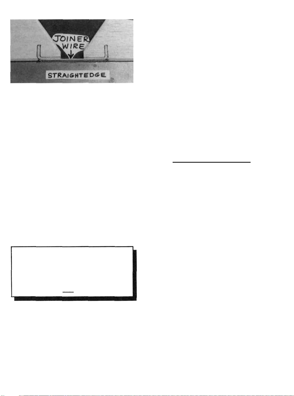
(See the photo at step 5 on page 15). HINT: Using an Xacto
knife, sharpen the inside of one end of a 1/8" diameter brass
tube, and use it to cut the groove in the leading edge of the
rudder.
BUILD THE FIN
D 6. Using a sanding block and coarse (50 or 80-grit)
sandpaper, sand both sides of the rudder to a taper as shown
on the plans. The trailing edge should end up approximately
3/32" wide and have a rounded shape. (Do not sand to a sharp
edge). Sand the top edge to a rounded shape. Sand the
leading edge to a "V-shape" as shown on the plan.
D 7. Check the plans and mark the location of the
tailgear on the rudder. Drill a 7/64" hole in the rudder (the
D 1. In the same manner as the rudder, build the fin using
the 1/4" x 3/4" and 1/4" x 1/2" balsa sticks. Also, cut 1" from
the 1/4" x 3/4" x 36" balsa stick, and from this small piece cut
the triangular gusset for the front comer of the fin.
D 2. Carefully draw a centerline on the leading and
trailing edges of the fin.
D 3. Sand the leading edge (only) to a round shape.
NOTE: The trailing edge, bottom edge and top edge
must not be rounded or V-shaped, instead, just sand
these edges flat and square.
7
Page 8
BUILD THE STABILIZER
You'll need the following parts:
1/4" x 1" x 17-7/8" balsa suck
1/4" x 3/4" x 36" balsa sticks
1/4" x 1/2" x 30" balsa sticks
1/4" shaped balsa stab tie
1/4" shaped balsa stab center
D 1. Tape waxed paper over the separate stabilizer draw-
ing on the fuse plan. In the same manner as the rudder, cut
balsa pieces and build the stab framework.
D 2. Sand a flat spot on the leading edge at the center, as
shown on the plan.
D 2. Sand the elevator tips to the shape as shown on the
plan.
D 3. Carefully draw a centerline all around the edges of
the elevators.
D 4. Sand the leading edge to a "V-shape, the trailing
edge to a round shape, and the outside edge of the tip to a
round shape.
D 5. Temporarily tape the elevators to the stab, providing
1/16" clearance between the elevator tip and the stab end.
D 3. Carefully draw a centerline on the leading and
trailing edges of the stab.
D 4. Sand the leading edge (only) to a round shape.
NOTE: The trailing edge and ends must not be rounded or Vshaped. Instead, just sand these edges flat and square.
BUILD THE ELEVATORS
You'll need the following parts:
1/4" x 3/4" balsa stick
1/4" x 1/2" balsa sticks
1/4" shaped balsa elevators
1/8" bent wire elevator joiner
D 6. Lay the 1/8" wire elevator joiner in place on the ele-
vators and mark its outline using a fine point felt-tip pen.
D 7. Accurately drill holes in the elevators for the 1/8"
wire joiner. Begin by drilling a 1/16" or 5/64" pilot hole, then
drill the final hole to a depth of 7/8" with a 9/64" drill bit.
(The hole is drilled slightly oversize to allow for positioning,
and to create a hard epoxy "sleeve" around the wire).
D 1. Position the shaped balsa elevators on the plan, then,
from the 1/4" x 1/2" sticks, cut pieces to make the elevator
tips. Glue these pieces to the ends of the elevators.
D 8. Use the sharpened 1/8" diameter brass tube to cut
grooves in the leading edge of the elevators to accept the
joiner wire.
D 9. Roughen the joiner wire with coarse sandpaper, then
clean the wire thoroughly with alcohol to remove any oily
residue.
8
Page 9
D 10. Trial fit the joiner wire into the elevators, then glue
it in using 5-minute or 30-minute epoxy. When gluing, lay
the elevators on a flat surface, with the leading edges along a
straightedge to insure perfect alignment
INSTALL THE HINGES (Do not glue)
NOTE: One-piece molded polypropylene hinges are
supplied in this kit. If you choose to use these hinges or
the' 'pinned' '-type hinges, you may cut the hinge slots at
this time. However, if you choose to use the one-piece
hinges that are paper covered for CA glue installation,
you may wait until after covering before cutting the hinge
slots, because this will be easier than trying to find the
slot locations under the covering.
D 1. Lay the rudder and elevators on the plan and mark
the hinge locations. Place the rudder against the fin TE and
transfer the marks over to the fin. Place the elevators against
the stab TE and transfer the marks over to the stab.
CAUTION!!!: You must use extreme care when
cutting hinge slots with an Xacto knife, to avoid
cutting yourself! If the balsa part breaks while you
are pushing on the knife, the blade could go into your
hand before you know it! A good precaution is to
wear leather gloves while performing the following
steps, and always cut awav from yourself.
B. Make three or four more cuts in the same line,
going slightly deeper each time. As you make these
additional cuts, work on going straight into the wood.
Continue this process while "wiggling" the knife
handle back and forth until the blade has reached the
proper depth for the hinge.
C. Trial fit the hinge into the slot. If the hinge is
difficult to push in, re-insert the knife and move it back
and forth in the slot a few times to enlarge the slot
D 3. IMPORTANT! Condition or "break-in" the
hinges by folding them back and forth several times.
D 4. Insert the hinges into the slots and trial fit the rudder
and elevators in place on the fin and stab. Do not glue the
hinges until after you have covered the model.
WING ASSEMBLY
BUILD THE WING PANELS
NOTE: The following instructions explain how to build
the wing directly on the plans. An alternate method is to
use a Great Planes Wing Jig (available from your local
hobby dealer). Many expert modelers prefer to use a
wing jig for high performance airplanes, as it helps to
insure a straight, warp-free wing, especially if you do not
have a workbench or building board that is perfectly flat.
If you choose to use the Wing Jig, please read the
instructions that are included with the jig before
beginning.
NOTE: It will be helpful to build the wing on a piece of
"Celotex" or other semi-soft (and flat) surface, into
which you may easily stick pins to firmly hold down the
wing pans while building, to avoid warps.
D 2. Cut the hinge slots on the accurate centerlines
which you previously drew, using an Xacto knife or a
slotting fork and slotting hook. (The recommended hinge
slotting technique is listed below).
A. Begin by carefully cutting a very shallow slit at
the hinge location. This first cut is to establish your cut
in the right place, so concentrate on staying on the
centerline and don't cut too deep!
D 1. Tape the plan to your flat work surface, and cover
the wing drawing with waxed paper (so you won't glue the
wing to the plan!). NOTE; If your work space is limited, you
may cut the left and right wing half drawings apart
D 2. The shaped and notched wing leading edges (LE)
and trailing edges (TE) are fastened together by thin strips of
balsa. Separate them by folding until the balsa breaks. Sand
away the excess balsa that remains along the edges after
breaking them apart, using a T-bar with 100-grit sandpaper.
9
Page 10
D 3. Before using the 3/8" x 3/8" x 32" hard balsa spars,
examine them carefully for possible imperfections. Look for
knots, soft spots, diagonal grain and any other imperfections.
If possible, position each spar so the imperfections are on the
outer half of the wing panel (toward the tip), where they will
be least affected by high stress. If the spars are warped
slightly, try to "balance them out" by installing the warped
spars in opposite directions (see sketch).
TWO WARPED SPARS INSTALLED
THIS WAY WILL RESULT IN A
STRAIGHT WING
TWO WARPED SPARS INSTALLED
THIS WAY WILL RESULT IN A
WARPED WING
D 4. Carefully punch out all the die-cut 3/32" balsa wing
ribs. Sand the edges slightly to remove any die-cutting ir-
regularities.
D 5. Draw an accurate centerline along the rear edge of
the notched balsa trailing edges.
NOTE: Follow steps 6 through 21 to build the RIGHT
wing panel, then repeat these steps to build the LEFT
wing panel.
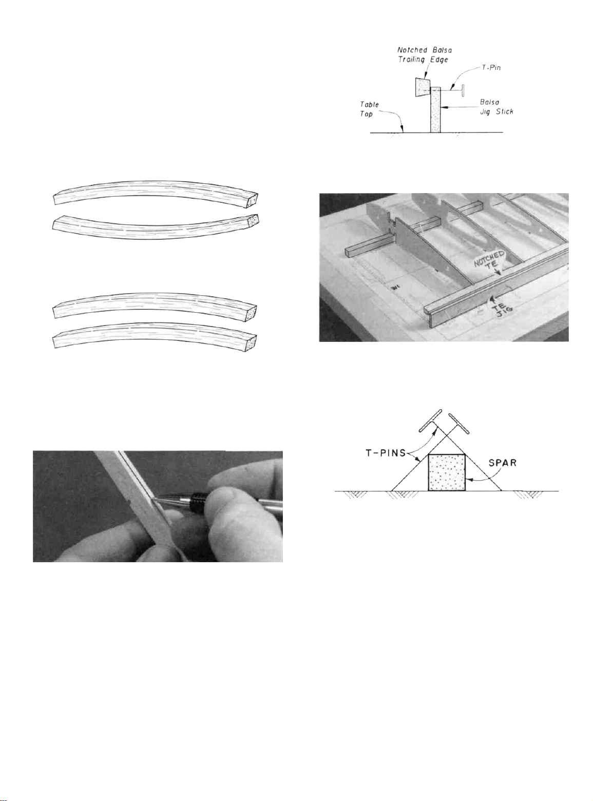
D D 6. Pin one of the notched balsa trailing edges to the
1/8" x 3/4" x 32" balsa TE Jig stick as shown in the following
sketch. Note that the top of the Jig stick must be on the
centerline which you have drawn on the trailing edge.
D D 7. Place one of the 3/8" x 3/8" balsa main spars on
the wing plan and pin the spar down with crossed T-pins as
shown in the following sketch. NOTE: The spars are cut
slightly too long, and the excess will be cut off later.
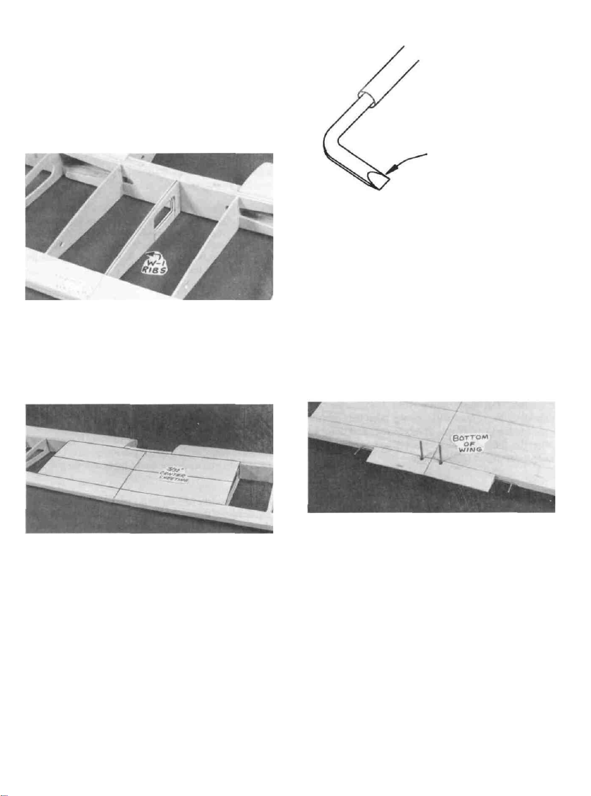
D D 8. Place one of the W-2 ribs and nine of the W-3
ribs on the spar in their approximate positions, but do not
glue.
D D 9. Hold the notched balsa trailing edge in place
(with TE Jig attached) and carefully work the ribs into the
notches, centering each rib up and down. Pin or tack glue the
TE Jig stick to your building surface, making sure the ribs
line up with the plan.
D D 10. Glue the W-2 and W-3 ribs to the TE. (Apply
glue sparingly, to avoid gluing the TE to the TE Jig).
10
Page 11
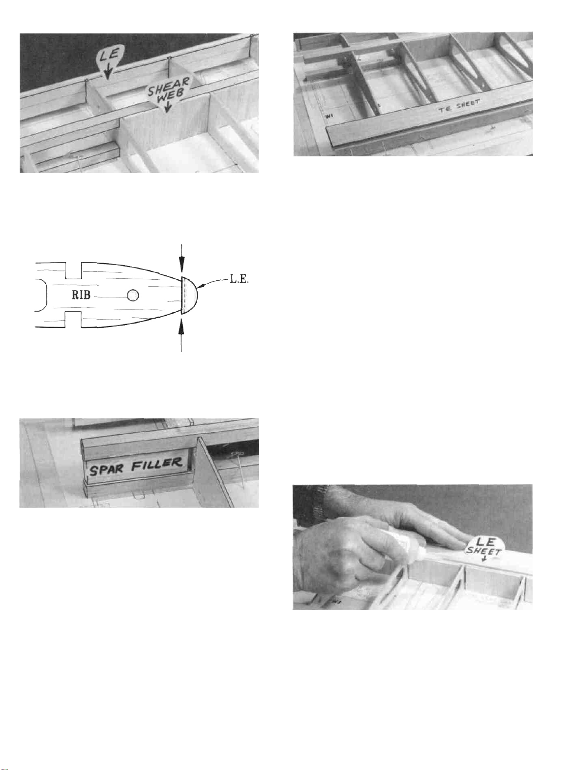
D D 11. Insert the front ends of the ribs into the notches
in the LE. NOTE: Position the LE as shown in the following
sketch. CENTER L.E.
VERTICALLY ON
FRONT OF RIBS
D D 15. Lightly sand the tops of the ribs to blend with
the notched trailing edge; then glue one of the 3/32" x 1-1/4"
x 32" balsa trailing edge sheets in place. NOTE': The edge
of the TE sheet may not be exactly straight, but just position
the sheet so it slightly overlaps the TE, and any overlap can
be sanded off later.
D D 12. Make sure the ribs are fully down on the plan
and all ribs are inserted into the LE notches. Glue the W-2 and
W-3 ribs to the LE and bottom spar.
D D 13. Insert the top spar into the notches in the ribs.
From the excess 1/4" x 3/4" balsa (used in the fin & stab construction), cut two pieces, 2-1/2" long. Insert one of these
1/4" x 3/4" x 2-1/2" balsa spar fillers between the top and
bottom spars in the area between W-l and W-2 (to hold the
spars apart at the proper spacing), then glue the top spar to the
ribs. Glue the spar filler to the spars.
D D 16.
the next step, use your T-bar to lightly sand off the edges of
the shear webs and smoothly blend the ribs to the spar.
D D 17. Prepare the 3/32" x 2-5/8" x 30" balsa leading
edge sheeting by sanding the front edge to a slight bevel so it
will fit snugly against the back of the leading edge. (Check by
trial fitting)
NOTE: It will be helpful to have the following items
handy for the next step... thin CA, thick CA, a wet cloth,
masking tape and T-pins. Read through the following
step and go through a "dry run" before actually gluing.
Before
applying
the leading edge
shecting
in
D D 14. Glue five of the pre-cut 3/32" balsa vertical
grain shear webs to the rear edge of the spars in the locations
shown on the plan. NOTE: The webs must be securely glued
to the spars, but it is not necessary to glue the webs to the ribs.
NOTE: In the next steps, maintain straightness by
keeping the wing down on the Hat surface and on the
TE
Jig.
D D 18. Position the leading edge sheeting at the rear
edge of the notched LE so it is just overlapping rib W-2.
Using thin CA, glue the front (beveled) edge of the leading
edge sheeting to the back edge of the LE. Now wet the top
surface of the sheeting so it will bend easier. Apply thick CA
glue to the top edge of the ribs and to the front half of the spar,
then immediately bend the sheeting down onto the ribs and
spar. Hold the sheeting down with masking tape, pins and
your hands until the glue has set.
11
Page 12
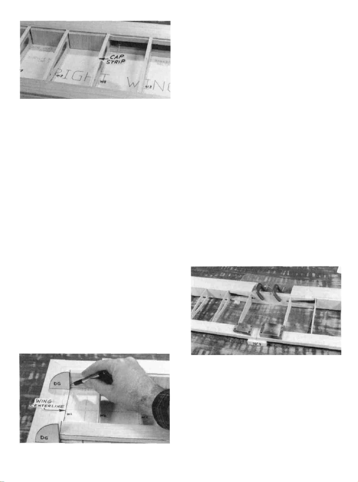
D D 19. From the 3/32" x 1/4" x 30" balsa sticks, cut and
glue cap strips to the top of the seven outside ribs. HINT:
For easier positioning of the cap strips, first mark the location
of each rib on the LE and TE sheeting. When finished,
remove the wing from the building board and turn it over
again.
D D 20. With the wing upside down, again use the TE
jig to support the TE. Then install the bottom TE sheeting, LE
sheeting and cap strips. IMPORTANT: To insure a
straight wing, you must pin the TE securely to the TE jig
and pin the jig to the building surface while the bottom
sheeting is glued in place!
D D 21. Trim the spars and sheeting flush with the tip
rib. Cut and sand the LE sheeting and LE flush with rib
W-2. and sand the entire wing panel smooth. Sand the leading
edge to smoothly blend with the LE sheeting (see the rib
cross-section on the plan for the desired LE shape).
wing plan, and block up the trailing edge 1/2", using the 1/2"
x 1/2" x 2" balsa blocks. Position the die-cut 1/8" ply
dihedral gauge (DG) on the wing centerline, as shown in the
photo, and mark cut-off lines on the spars, trailing edge and
TE sheeting. Carefully cut or sand off the spars and trailing
edge at these marks.
D 3. Accurately position the left wing panel on the left
wing plan. Mark and cut off the spars and TE as in step 2.
D 4. Lay a piece of waxed paper down at the center of the
wing, place the two wing panels together at the center, and
block up both wing tips 1/2-inch, and block up the trailing
edge 1/2-inch at the center (use the 1/2" x 1/2" x 2" balsa
blocks provided). If the spars do not mate with one another,
sand them slightly until they do.
D 5. Trial fit the die-cut 1/8" ply dihedral braces on
both sides of the spars to make sure they will readily slide
into place.
NOTE: Read steps 6 and 7, then make a "dry run'
through these steps before actually proceeding.
NOTE: 30-minute epoxy is strongly recommended
for the wing joining process.
D 22. Now go back and repeat steps 6 through 21, to build
the other wing panel. NOTE: The two wing panels are
identical, so you may build on the same plan.
JOIN THE WING PANELS
D 1. Designate one wing panel "RIGHT" and the other
"LEFT".
D 2. Accurately position the right wing panel on the right
D 6. Mix up a batch of 30-minute epoxy and smear it on
the dihedral braces, spars, spar ends, and the mating surfaces
of the trailing edge. Slide the dihedral braces in place, push
the wing panels together and immediately proceed to the
next step.
D 7. With the wing tips blocked up 1/2-inch, carefully
align the spars and TE of both wing panels. Clamp the
dihedral braces to the spars and apply a few pieces of masking
tape to hold the trailing edges in correct alignment. Wipe up
the excess epoxy with a tissue. Allow the epoxy to fully
harden before disturbing the wing.
12
Page 13
INSTALL CENTER RIBS AND SHEETING
D 1. Use a sanding block to sand off any excess epoxy on
the top and bottom of the spars in the center of the wing.
D 2. Remove the die-cut aileron servo "punch-outs"
from the two W-l wing ribs, then glue the W-l ribs together,
and trim and sand them to fit between the TE and the dihedral
brace. Glue the ribs in place with the opening for the aileron
servo facing down.
FILE END TO
WEDGE SHAPE
D 2. Roughen the surface of the plastic bearing tubes
with 100-grit sandpaper.
D 3. Clean the torque rods and bearing tubes with alco-
hol.
D 4. Find the two grooved, tapered balsa center trailing
edge pieces. Lay them on the plan and check them for length.
Mark and cut them off to match the plan, if necessary.
D 3. Using the 3/32" x 3" x 8-7/8" balsa sheets, glue the
center section sheeting in place on the top and bottom, as
shown on the plan. Sheet all the way to the front of the front
dihedral brace.
INSTALL AILERON TORQUE RODS
D 1. Roughen the short end of the aileron torque rods
with 100-grit sandpaper, and file the same end to a wedge
shape.
D 5. Trial fit the torque rods into the center TE pieces.
Determine from the plan where to cut the clearance notches,
which will permit the torque rod horns to travel freely. Also
cut small clearance notches in the wing TE. Note: The
torque rod horn (threaded end) must exit the BOTTOM of
the wing!
D 6. Slide the plastic bearings toward the threaded end of
the torque rods, then use a toothpick to apply a small amount
of petroleum jelly to the ends of the plastic tubes (to help
prevent glue from getting inside and locking up the torque
rods).
D 7. Use 5-minute epoxy or CA to glue the plastic bearing tubes into the grooves in the center TE pieces. Wipe off
any excess glue and allow it to harden.
13
Page 14
use a scissors or a paper punch to cut holes in the glass cloth
for the aileron torque rod horns.
D 3. Wrap small pieces of masking tape around the
exposed portions of the aileron torque rods to protect them
from the spray adhesive in the next step.
D 8. Trial fit the trailing edge/torque rod assembly onto
the wing trailing edge. Sand the center trailing edge pieces
slightly where they join, for a good fit. The top and bottom
surfaces of these pieces should blend smoothly with the top
and bottom of the
(threaded ends pointing DOWN). SUGGESTION: If you
are using 5-minute epoxy, glue only one piece at a time. and
use masking tape to hold it to the wing TE, to aid in correct
positioning.
wing.
Glue
these pieces
in
place with epoxy
FIBERGLASS THE CENTER SECTION
NOTE: Because of the high stresses in the center of
this wing, fiberglass reinforcement is REQUIRED.
Please do not omit this important section!
NOTE: If you have previous experience applying
fiberglass, feel free to use your favorite method,
providing that it results in a strong bond between the
glass cloth and the wood. If this is your first time, we
offer the following suggested method, which is the
fastest and easiest we have seen.
D 4. Spray a very light mist of 3M "77" Spray
on the center section in the area to be glassed. Hold the spray
can at least 12" away from the surface when doing this to
avoid a heavy buildup. The purpose of this is only to give the
wood a little "tackiness". If you apply too much spray it
could result in a poor glue bond.
D 5. Lay the glass cloth in place on the top and bottom of
the wing. Gently press the cloth in place, working out all the
wrinkles. The "77" spray adhesive should hold the cloth
down to the surface, but will permit you to lift and reposition
the cloth if you make a mistake. Don't attempt to wrap the
cloth around the trailing edge.
D 6. Working outdoors or in a very well-ventilated area
apply thin CA glue to the glass cloth. Begin by running a
bead of glue down the center of the glass cloth strip, then
continue applying the glue in lines until all the cloth has been
secured. Run the thin CA out 1/4" beyond the edges of the
glass cloth to help protect the balsa sheeting when sanding
later. WARNING: This operation produces a larger than
normal quantity of CA fumes, so adequate ventilation is a
must!
D 7. Inspect the surface of the glass cloth. If any areas are
not glued down, apply a couple more drops of CA glue and
press down with a piece of waxed paper until the glue sets.
Adhesive
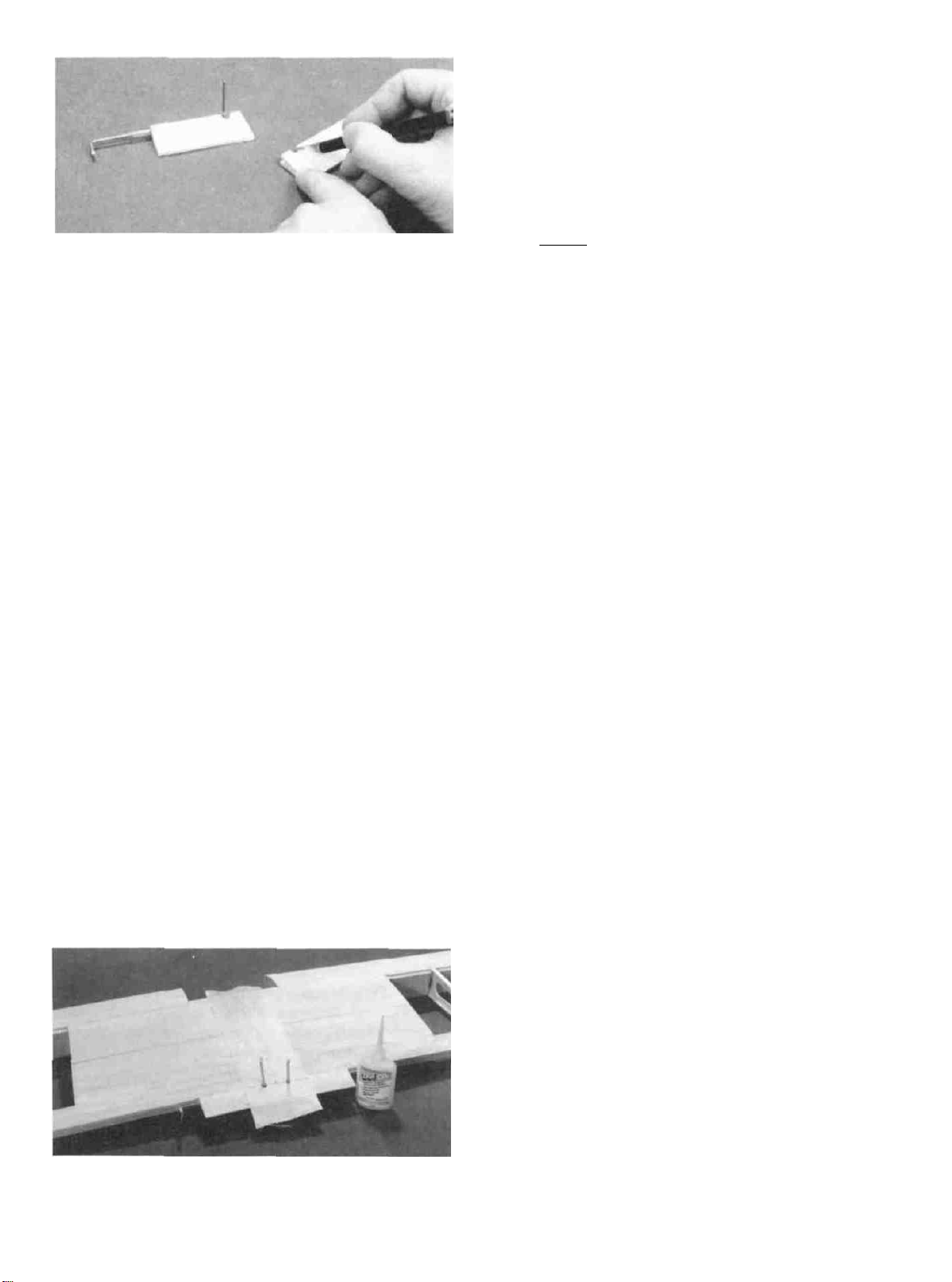
D 1. Make location marks for the fiberglass reinforcement cloth, 1-1/2" each way from the wing centerline.
NOTE: The cloth will be applied to the top and bottom
surfaces only. Do not apply cloth to the front surface of the
front dihedral brace.
D 2. Cut the length of 3" glass cloth in half, making two
equal lengths. Trial fit the fiberglass cloth in place. You can
D 8. To make sure the glass cloth is fully "wetted out"
and bonded to the balsa, you may apply more thin CA, a few
drops at a time, and spread it out with a piece of waxed paper.
D 9. After the glue has set, trim the excess cloth at the
front of the front dihedral brace and at the trailing edge with
a sharp Xacto knife followed by a sanding block.
D 10. Carefully sand the edges of the glass cloth with a
T-bar sander with 80 or 100-grit sandpaper, smoothly blend-
ing the edges to the wing. Also, lightly sand the surface of the
glass cloth with a piece of fine sandpaper held in your fingers
to remove any rough spots. WARNING: When sanding
fiberglass, wear a dust mask to avoid breathing airborne
glass libers.
D 11. You may now clean up any 3M "77" Overspray with
a tissue dampened with lighter fluid or K&B thinner.
14
Page 15

INSTALL WING TIPS
NOTE: The wing tips will be cut and carved from the
1/4" x 1-3/4" x 11" balsa blocks.
D
1.
Draw a centerline on the ends of the
wing tip blocks.
D 2. Securely glue the wing tip blocks to the ends of the
wing, lining up the centerlines you previously drew.
wing
and on the
D 3. Hold the ailerons in place in the openings, with the
torque rods resting on top of the ailerons. Mark the torque
rod locations on the top of the ailerons.
D 4. Drill a 7/64" hole in the ailerons at the torque rod
locations, starring at the leading edge centerline and drilling
straight in to the proper depth.
D 3. Cut, carve and sand the wing tips to blend with the
wing, and to the shape as shown on the plan. NOTE: Leave
the tips oversize in the area of the ailerons, for now.
INSTALL AILERONS
NOTE: Do not glue the aileron hinges until after your
model has been covered.
D 1. Draw an accurate centerline along the LE of the
tapered balsa ailerons and the wing TE.
D 2. Check the length of your ailerons against the actual
aileron openings and trim the ailerons as necessary. You
should provide approximately 1/16" gap at each end of the
ailerons.
D 5. Use the sharpened 1/8" diameter brass tube to cut a
groove in the leading edge of the ailerons to accept the torque
rods. Trial fit the ailerons onto the torque rods and cut as
necessary until they fit.
D 6. Lay the ailerons on the plan and mark the hinge
locations on the ailerons. Place the ailerons against the wing
TE and transfer the marks over to the wing.
D 7. Cut the hinge slots in the ailerons and wing TE using
an Xacto knife. (The suggested procedure was given on page
9).
D 8. IMPORTANT! Condition or "break-in" the
hinges by folding them back and forth several rimes.
D 9. Using a T-bar with 50 or 80-grit sandpaper, sand the
leading edge of the ailerons to the same "V-shape as shown
on the wing cross-section drawing on the plan.
D 10. Insert the hinges into the slots and trial fit the
ailerons in place on the wing. Do not glue the hinges until
after you have covered the wing.
15
Page 16

There should be no hinge gap!
INSTALL WING BOLT PLATE
Therefore, if you are using "pinned" hinges, you must
cut away balsa to make room for the center portion of the
hinge.
NOTE: Now is a good time to finish the wing tips. Tape
the ailerons on in the neutral position, and sand the wing
tips to blend with the ailerons.
TEMPORARILY INSTALL WING DOWELS
(Do not glue)
D 1. Use a sanding block to custom fit the die-cut 1/8" ply
wing dowel plate to the front of the dihedral brace, sanding
as necessary to blend with the top and bottom of the wing.
D 1. Mark a centerline on the 1/16" x 3-1/2" x 1 -1/2" ply
wing bolt plate.
D 2. Use a sanding block to "feather'' three edges of the
wing bolt plate, leaving the TE square. Doing so will make
it easier to cover, and will blend more smoothly with the
wing.
D 3. Position the wing bolt plate on the top of the wing,
and accurately line it up with the wing TE and centerline.
Glue it in place.
D 2. Securely tape the dowel plate in place (it must not
move while drilling), then drill 1/4" holes through the dihedral braces, using the dowel plate holes as a drill guide. The
drill must extend at least 7/8" into the wing to penetrate the
front and rear dihedral braces.
D 3. Sand one end of each wing dowel to a rounded or
pointed shape. This is the end that will be inserted. Do not
sand the other end at this time.
D 4. Trial fit the dowels into the dowel holes, and trial fit
the dowel plate over the dowels. If the dowels fit too tightly,
you may enlarge the holes slightly using a round file, or you
may sand the dowels down slightly. Do not glue the dowels
or dowel plate in place at this time.
D 4. Sand the wing bolt plate flush with the wing TE.
INSTALL WING STRUT PLATES
D 1. Glue the die-cut 1/8" ply wing strut plates in place
on the BOTTOM of the wing in the locations shown on the
plan. The front plates are glued to the spar and the rib, and are
flush with the spar. The rear plates are glued to the rib, TE and
TE sheeting.
D 2. Glue scraps of 3/32" balsa to the front plates, and
16
Page 17

sand them to blend with the surface of the wing. Poke several
holes with a pin near the center of the plate, apply thin CA,
then sand smooth. This will harden the balsa and prevent
crushing when the strut straps are installed later.
FUSELAGE ASSEMBLY
PREPARE FUSE SIDES
sides "RIGHT" and "LEFT". From the front edge of both
sides, accurately measure back 13/32" and draw a line
parallel with the front edge.
D 6. Glue the two die-cut 1/8" ply fuse doublers to the
fuse sides, making a right and a left side. The front edge of
both doublers bull against the 13/32" line.
D 1. Working on a flat surface covered with waxed paper,
trial fit the die-cut 1/8" balsa upper fuse side and aft fuse side
together at the "zig-zag" joint, sanding as necessary for a
good fit. While assembling, lay a straightedge along the top
edge of these parts, to make sure they are properly lined up.
Glue these parts together.
D 2. Glue the die-cut 1/8" balsa lower fuse side to the
upper fuse side and aft fuse side.
D 3. Inspect the glue joints for gaps, add thick CA glue if
necessary. Sand the glue joints smooth on both sides using a
T-bar and 100-grit sandpaper, then repeat the above steps to
make the other fuse side.
D 4. Place the two assembled fuse sides together. Sand
the edges as necessary to make the two sides identical.
D 5. As shown in the following sketch, designate the fuse
D 7. Find the 1/8" x 5/32" x 4" Hardwood Spacer and glue
it to the LEFT fuse side and the fuse doubler. REFER TO
THE ABOVE SKETCH TO AVOID CONFUSION.
IMPORTANT NOTE: When assembling the
fuselage you must install the die-cut FUSE TOP and
FUSE BOTTOM correctly. When these parts are
correctly installed, the front edges of the fuse top
and fuse bottom will match up with the front edge
of the fuse side doubler (right side) and with the
front edge of the hardwood spacer (left side).
ASSEMBLE LOWER FUSELAGE
NOTE: The lower fuselage will be assembled upside
down on the plan.
17
Page 18

D 1. Trial fit (do not glue) the following parts together,
upside down on a flat surface: Die-cut 1/8" ply fuse top, fuse
sides, die-cut 1/8" ply F-2, F-3, and the fuse bottom. Check
the fit of all parts and trim, file or sand as necessary for a good
fit. NOTE: The front portion of the fuse is "self-aligning,"
but it is important that the top edges of the fuse sides rest on
a flat surface.
the cross-braces (the formers are upside down), and sand the
edges of the formers slightly to match the angle of the fuse
sides. Glue the formers to the cross-braces, making sure that
each former is installed perpendicular to the building
surface. Use a carpenter's square or draftsman's triangle to
insure correct installation of F-4.
D 6. Now carefully align the fuse assembly on the plan.
Line up the aft edge of the fuse top with the front edge of the
dash. Hold the front portion of the fuse securely by placing
books or other suitable weights on the fuse. NOTE: The
front of the fuse sides will not match the plan, because the
fuse is upside down.
D 2. Once you have everything fitting properly, re-as-
semble the above parts, using clamps, pins, tape and weights
to hold everything together and flat on the workbench. Make
sure F-3 is positioned perpendicular to the work surface.
There should be waxed paper underneath to prevent gluing
the fuse to the plan. Apply thin CA glue to the joints. Remove
the assembly from the workbench and inspect the glue joints,
following with thick CA glue in any joints that are not tight
fitting.
D 3. Tape the fuselage plan to your workbench and cover
the Fuse Top View with waxed paper.
D 4. From the 1/4" x 1/2" x 14-7/8" balsa stick, cut the
four cross-braces to the exact size shown on the plan. Pin
these cross-braces securely to the building surface, aligning
them accurately.
D 7. Pull the aft ends of the fuse sides together and glue
the fuse sides to F-4, F-5, F-6 and F-7. Do not glue the aft ends
of the fuse sides together yet.
D 8. Study the plans and note that you will attach the
engine mount directly to the 1/4" ply firewall (F-l) if a
4-cycle engine is to be used. Before installing F-l, you may
drill F-1 for your engine mount and install the 6-32 blind nuts.
If you will be using the engine mount supplied in the kit, you
may cut out the F-1 drawing from the plans, tape it to F-1 and
use it as a guide for drilling the four 5/32" holes. If you will
be using a different mount, note that the mount should not be
positioned on the vertical and horizontal centerlines of F-l,
but should be offset approximately 5/32" toward the left side
of the airplane. Drill the holes and install the blind nuts on the
back of F-l, pressing them in with a pliers or a vise.
NOTE: 2-Cycle engine installation will be covered
later in the building sequence.
D 5. Trial fit formers F-4, F-5, F-6 and F-7 to the front of
D 9. Trial fit F-1 to the fuselage and sand as necessary to
18
Page 19

fit between the fuse sides. Use 30-minute or 5-minute epoxy
to securely glue F-l to the fuse sides, holding with clamps or
tape until the glue has firmly set. NOTE: Before the glue
sets, double check to make sure F-l is properly aligned with
the top edge of the fuselage, and fully back against the fuse
doublers. After the glue has fully hardened, sand off the front
of the fuse sides flush with the front of F-l.
D 10. Glue the die-cut 1/8" ply F-1B, F.2B, F-2C, F-3B,
and the 1/4" ply main landing gear mounting plate to the
fuse bottom. NOTE: F-1B should line up with the front of
F-l, and you should use epoxy for the L.G. plate.
outside edge of the bottom of the fuse sides. Add small pieces
of scrap balsa in the front corners (at F-2C) as shown in the
photo.
D 14. Using a sanding block, sand the 3/4" triangles on a
Straight line from F-2C to F-3B.
D 11. Glue the die-cut 1/8" balsa center stringer between
F-1B and F-2B, along the centerline of the fuselage.
D 12. Find the 3/32" x 3" x 9" balsa sheet and cut it in half
to make two 4-1/2" lengths. Glue one edge of one of these
sheets to the bottom edge of the fuse side, beginning at the
rear edge of F-2B and extending past F-1B. Wet the sheeting
thoroughly with warm water or alcohol in the area to be bent,
then bend the sheeting over the formers and glue it down.
Trim the sheeting at the centerline of the center stringer.
Repeat this process for the other side. Trim and sand the
sheeting flush with the front of F-1B and the rear of F-2B.
D 13. From the 3/4" x 9-3/4" balsa triangle stock, cut two
pieces to fit between F-2C and F-3B, and glue them along the
D 15. Cut one of the 1/2" x 36" balsa triangles in half to
make two 18" lengths. Glue these triangles along the outside
edge of the bottom of the fuse sides between F-3B and F-7.
D 16. Find the two die-cut 1/8" balsa stringers that fit
between F-3B and F-4, and glue them to the inside edge of the
1/2" balsa triangles, just behind F-3B.
D 17. Using a long sanding block with 50 or 80-grit sand-
paper, sand the above triangles and stringers to taper on a
straight line from F-3B to F-7 as shown on the fuse plan side
view. In other words, you will sand off almost nothing at
F-3B, and almost all of the triangle at F-7.
19
Page 20

IMPORTANT NOTE: When performing steps 16-18,
it is possible that adding the triangles may have pulled the
aft portion of the fuse out of alignment slightly. Check
for this by positioning the fuse on the plan. If this is the
case. relieve the stresses caused by the triangles by
making razor saw cuts in the triangles until the fuse
straightens out. After doing so, apply thin CA to the saw
cuts.
D 18. From the 3/32" x 3" x 32" balsa sheet, cut and glue
pieces of cross-grain sheeting to the bottom of the fuse,
beginning at the front of F-2C and running to the aft end of the
fuse. NOTE: While applying sheeting to that portion of the
fuse aft of F-7, temporarily pin the tapered balsa tail filler in
place to maintain the proper separation of the fuse sides at the
aft
end.
D 19. Sand the edges of the bottom sheeting at a 45-degree
angle to blend with the triangle stock, as shown on the former
cross-sections on the plan. (This results in a shape that is
reasonably close to the full-size Super Decathlon fuselage).
and glue them to the top of F-1. The front of F-1T must line
up with the front of F-1.
D 2. Glue the die-cut 1/8" ply DASH in place in the
notches in the fuse side doublers.
D 3. Glue the 3/16" x 3/16" x 3-1/4" balsa top front
stringer into the notches in F-1T and the DASH. Sand the
front and rear ends of the stringer flush with the formers.
D 4. Cut the 1/16" x 3" x 8" balsa sheetin half to make two
pieces 4" long. Using the same technique you used to apply
the bottom front sheeting, glue the 1/16" top front sheeting
to F-1T and the DASH. Sand the sheeting flush with the
formers. Sand the fuse sides to a rounded shape to blend with
the sheeting (See the cross-section drawing of F-l on the
plan).
ASSEMBLE UPPER FUSELAGE
NOTE: You may now fuelproofthe inside of the fuel
tank compartment and the front of F-l by brushing on a
coat of polyester resin or 30-minute epoxy thinned with
alcohol. You may wait until it is time to install the fuel
tank, but it is easier to do so at this time.
D 1. Glue the two die-cut 1/8" ply F-1T formers together,
D 5. Glue F-2T to the front of F-2.
Glue F-4T to the front of F-4.
Glue F-5T to the front of F-5.
Glue F-6T to the front of F-6.
D 6. Draw a line on F-7T, 1/4" up from the bottom edge.
Then glue F-7T to the front of F-7, aligning the line with the
top edge of F-7. Install this former accurately!
D 7. Find the die-cut 1/8" ply wing saddle doublers.
Carefully position them on the cabin sides, aligning the top
20
Page 21

edge and the rear window opening. Glue the doublers in place
making a RIGHT and a LEFT cabin side!
D 8. Trial fit the die-cut 1/8" ply cabin sides into the
notches in the fuse sides, sanding as necessary for a good fit.
Glue the cabin sides to the top edge of the fuse sides and to
F-5T.
D 11. Securely glue the die-cut 1/8" ply F-2D to the
tapered balsa filler and to the cabin sides.
D 12. Find the 1/4" ply wing hold-down plate and trial fit
it into the notches in the fuse side doublers, sanding as
necessary for a good fit. Glue the hold-down plate in place
securely, using 30-minute epoxy, then build up small fillets
of epoxy all around the plate to lock it in place.
D 9. Glue the cabin sides to F-4T while pushing F-4T
against the aft ends of the wing saddle doublers; and glue the
cabin sides to F-2T while pushing F-2T against the front ends
of the wing saddle doublers.
D 10. Trial fit the 4-3/16" length of tapered balsa at the top
rear edge of F-2T, between the cabin sides, and glue in place.
D 13. Securely glue the two die-cut 1/8" balsa stab sup-
ports and the tapered balsa tail post to the aft end of the
fuselage. IMPORTANT: Before gluing these parts, tape
and pin them in place and check alignment as follows: The
tail post must be installed perpendicular to the top edge of the
fuselage, and must be vertical. Cut and sand off the top of the
tail post flush with the top of the stab supports, and sand the
aft end of the stab supports to blend with the fuselage. See
- sketch at the top of the next page.
Page 22

TAPERED TAIL POST
, (Sand off flash with top
of stab support)
TAPERED TAIL POST
(View from rear)
STAB SUPPORT
LOWER FUSELAGE
two stringers 12" long. Cut these pieces to run from the notch
in front of F-5T to the aft edge of F-7T. Glue the stringers to
F-5T, F-6T and F-7T, then sand to blend with the formers.
D 16. Cut the 1/2" x 36" balsa triangle in half to make
two pieces 18" long. Cut these pieces to run from the front
edge of F-4T to the aft edge of F-7T. Try pressing the
triangles down onto the 3/16" x 3/16" stringers. If the
triangles are hard balsa, you may have to make several partial
saw cuts with a razor saw (as shown in the photo) to permit
easy bending. Make the cuts approximately 2" apart. Glue
the triangles to the formers. If you made saw cuts, you should
now apply thin CA to each cut. Finally, use your sanding
block to sand the triangles down to blend with the lops of the
formers.
D 14. Sand the die-cut 1/8" ply stab base as necessary for
a good fit between the stab supports, then glue the stab base
in place, flush with the top edge of the stab supports.
NOTE: The glue joints where the stringers meet the stab
saddle area are critical; therefore, please look them over
again and add thick CA or 5-minute epoxy to insure very
strong glue joints in that area.
D 17. Prepare the top rear sheeting as follows: Cut the
3/32" x 2-5/8" x 13-1/8" balsa sheet on a diagonal as shown
in the following sketch...
Now edge glue the two pieces together as shown in the
following sketch...
D 15. Cut the 3/16" x 3/16" x 24" balsa stick in half to make
Sand the glue joint smooth, using
100-grit sandpaper.
22
your T-bar
sander with
Page 23

D 18. Glue the top rear sheeting to the top edge of the
formers and stringers, beginning at the front of F-4T and
running to the aft edge of F-7T. Sand the edges of the top
sheeting at a 45-degree angle to blend with the triangular
stringers (see the cross-sections on the fuse plan).
MOUNT THE WING TO THE FUSE
D 1. Sand the entire wing saddle area lightly until the
wing saddle doublers and cabin sides are flush.
D 2. Apply six layers of masking tape onto the wing
saddle to hold the wing off the saddle slightly. (This will
simulate the thickness of the covering material and wing
seating tape).
D 3. Make fuselage centerline marks on the top of F-2D
and at the front edge of the top rear sheeting. Also mark the
wing centerline on the front and rear edges of the wing.
the holes in the dowel plate as a guide. Note: Drill only to a
depth of 3/8", and try not to drill through F-2T.
D 9. Use a razor saw to separate the dowel plate from
F-2D.
D 10. Use a pliers to grasp the ends of the wing dowels and
pull them out. Now you may slightly round (or chamfer) the
ends of the dowels for easier insertion into F-2D. Mix up a
batch of 30-minute epoxy, spread it on the front surface of the
wing and press the dowel plate in place. Use a long stick to
work some of the epoxy into the dowel holes, smear epoxy on
the dowels, then re-insert the dowels into the wing, leaving
them protrude approximately 5/16". Wipe away all excess
epoxy, then allow the epoxy to fully harden. Sand the dowel
plate to blend smoothly with the top and bottom sheeting.
D 4. Hold the die-cut 1/8" ply wing dowel plate in place
against the front of the wing (do not glue).
D 5. Insert the 1/4" wing dowels through the dowel plate
and into the wing until they are flush with the front surface of
the dowel plate. The dowels should insert easily, but be held
in the wing by a friction fit. If necessary, use a 1/4" round file
to enlarge the holes slightly.
D 6. Trial fit the wing into the wing saddle. If the wing
is slightly too large (front to rear) to fit into the saddle, sand
the rear edge of the saddle and the wing trailing edge slightly
until it fits.
D 7. Center the wing, side to side, by aligning the center-
line marks you previously made. Now tack glue the wing
dowel plate to the upper comers of F-2D, using a couple drops
of thick CA and CA accelerator spray (spray first, then apply
a drop of glue, to prevent the glue from running down
between the plates.
D 8. Gently remove the wing, leaving the dowel plate at-
tached to F-2D. Then drill 1/4" holes through F-2D using
D 11. Place the wing back in the saddle and carefully align
it according to the above sketch. While holding the wing in
its proper position, make alignment marks on the wing TE
and the front of the fuse top sheeting so you may easily realign the wing later.
D 12. Study the wing plan and the sketch at the top of the
next page to determine where the wing bolt holes are to be
drilled. By measuring, transfer the locations to the wing bolt
plate on the top of the wing. After marking the bolt locations,
replace the wing in the saddle.
23
Page 24

DRILLING LOCATIONS
D 17. Trial fit the wing to the fuse using the two 1/4-20
nylon bolts provided. You may cut the bolts off to their proper
length, so they protrude about 1/4" below the hold-down
blocks in the fuselage. Check the incidence of the wing using
the instructions provided at the bottom of page 41.
D 18. Glue the two 1/4" xl -3/4" x 2-1/2" balsa center nose
fillers to the inside edges of the W-2 ribs. Then sand the edges
of these fillers to blend with the LE and LE sheeting.
D 13. Holding the wing firmly in place, drill 13/64" holes
at the locations you marked in step 12, drilling down through
the 1/16" ply wing bolt plate and through the 1/4" ply hold-
down blocks in the fuselage. Try to drill straight in, perpendicular to the 1/16" ply bolt plate. IMPORTANT!: Do not
allow the wing to move while drilling!
D 14. Remove the wing and re-drill the holes in the wing
only to 1/4".
U 15. Use a 1/4-20 tap and a tap wrench to cut threads in
the ply hold-down blocks in the fuselage.
D 19. Trial fit the wing on the fuselage, and sand the center
nose fillers to mate with the front of the 1/8" ply cabin sides.
Provide at least 1/16" clearance on both sides, between the
wing and fuse, to allow for the thickness of the covering
material and windshield.
MOUNT STABILIZER AND FIN
D 1. Lightly sand the stab saddle area smooth with a
T-bar or sanding block.
D 2. Accurately measure the trailing edge of the stabi-
lizer and mark the center point.
D 3. Temporarily mount the wing in the saddle (for reference).
D 16. Harden the threads in the hold-down block with thin
CA glue, then re-tap the threads after the glue is completely
dry.
D 4. Lay the stab in position on the stab saddle with the
center point lined up with the tail end of the fuselage.
Carefully check the stab alignment by standing directly
24
Page 25

behind the fuselage and'' eyeballing" whether or not the stab
is level with the wing. Sand the stab saddle (a little at a time!)
until it rests in proper alignment. Also measure from the rear
comers of the stab to a point on the fuse centerline at the top
of F-2T, and pivot the stab until both measurements are equal.
With the stab in alignment, make a mark on the front of the
stab and a corresponding mark on the stab base, which will be
used for rapid alignment when gluing.
D 5. Mix up a batch of 5-minute or 30-minute epoxy and
apply it to the stab saddle. Press the stab into position and
hold or pin in proper alignment until the glue has firmly
set. Wipe off any excess epoxy before it sets up.
D 6. From the 3/8" balsa triangle supplied, cut and se-
curely glue fillets under the stab, at the stab/fuse joint
tail filler for the bottom rudder hinge and the tailgear
bearing. Trim off the bottom of the rudder, if necessary, to
match the bottom of the fuse.
D 10. Glue scraps of balsa to fill the area between the front
of the stab and the rear edge of F-7T, then sand to blend with
the stringers. NOTE: It is a good idea to glue these pieces in
with epoxy as a means of locking the stab area to the top
sheeting and stringers.
D 11. From a scrap of 1/4" balsa, cut a small dorsal fin, as
shown on the plan, and glue it to the front of the fin and the
top sheeting. Round the leading edge of the dorsal fin to blend
with the leading edge of the fin.
D 7. Trial fit the fin on the stab. The fin trailing edge
must line up with the aft end of the fuselage. If the fin
protrudes too far aft, sand a small amount off the front of the
fin.
D 8. Carefully align the fin on the stab. The fin must be
positioned perpendicular to the stab and must line up with
the fuselage centerline EXACTLY! File the slot in the stab
base if necessary to properly align the fin. Securely glue the
fin in place with epoxy.
D 9. Temporarily attach the elevators and rudder to
check their fit and operation. Note that you must cut a notch
in the rudder leading edge to clear the 1/8" wire elevator
joiner. At this time, you should also cut the slots in the fuse
FINAL ASSEMBLY
ENGINE INSTALLATION
NOTE: If you are using a 4-cycle engine, install your
engine mount directly onto F-1, in the location shown on
the plan. If you are using a 2-cycle engine and a Great
Planes engine mount, you must assemble and install a
"2-Cycle firewall", which positions the rear edge of the
mount 21/32" forward of F-l. It may be possible to
mount directly to F-l if you are using a mount that has
extra-long arms. Plan your installation carefully before
beginning.
INSTALL "2-CYCLE FIREWALL"
(for 2-Cycle engines only)
NOTE: The 2-Cycle firewall consists of five 1/4" ply
parts...
(1) -1/4" x 2-1/16" x 2-9/16" (FRONT)
(2) -1/4" x 13/32" x 2-1/16" (TOP & BOTTOM)
(2) -1/4" x 21/32" x 2-9/16" (SIDES)
25
Page 26

DRILL ENGINE MOUNT (Great Planes
MM40 or MM60 mounts)
D 1. Align the engine on the mount and mark the mount-
ing hole locations on the mount. At the marked locations,
accurately drill 7/64" (or #36) holes. NOTE: If you have
access to a drill press, use it for drilling these holes to insure
that they are drilled vertically.
D 1. Trial fit the five parts together to check how they fit
(see the plans and the photos). Sand the parts as necessary for
a good fit. Assemble the parts with 5-minute epoxy, and wipe
up the excess glue inside the "box" before it sets up.
D 2. Hold the engine mount on the 2-cycle firewall in the
location shown on the plan, and mark the boll locations
through the mount. Drill 5/32" holes at the bolt locations,
then install the 6-32 blind nuts inside the box. You may tap
the blind nuts in with a hammer, or pull them in using a 6-32
bolt (with a flat washer under the head of the bolt). Apply CA
glue or epoxy around the rim of the blind nuts to hold them
permanently in place. Test the threads of each blind nut with
a 6-32 bolt
D 2. Now you may use one of the following methods to
attach your engine to the mount:
Method 1: Screw the #6 x 3/4" sheet metal screws
(provided in the kit) through the engine mounting flange and
into the mount. When first installing these screws, put a drop
of oil into each screw hole.
Method 2: Cut threads in the holes you just drilled using
a 6-32 tap and tap wrench. If you use this method you'll have
to supply your own bolts (6-32 x 1" socket head cap screws)
for attaching the engine to the mount
INSTALL SERVOS, HORNS AND
PUSHRODS
D 3. Study the cross-section drawing of F-l (on the fuse
plan), and, by measurement, mark the location of the "box"
on F-l (Note that the box and mount are offset 5/32"
toward the left side of the fuse). Glue the firewall box to F-
1 with epoxy. Apply a small fillet of epoxy around the
perimeter of the box, for added security.
D 1. Study the plans to determine the location of the
aileron servo cutout. Mark the location on the bottom of the
wing and cut an opening in the fiberglass and sheeting slightly
larger than your servo. CAUTION: Do not cut into the wing
spars or shear webs!
D 2. Remove a sufficient portion of the W-l ribs to fit
your servo, leaving "shelves" on which to glue the 1/8" ply
rails. (See the plan to determine the depth). NOTE: A
Dremel Moto Tool with a 1/8" router bit is excellent for this,
but it may also be done with an Xacto knife and a long-nose
pliers.
D 3. Make two servo rails from the 1/8" ply die-cutting
scrap, and glue them in place. (See the side view of the
aileron servo installation on the plan).
26
Page 27

D 4. Mount the aileron servo using the screws provided
with your radio.
D 5. Screw the nylon aileron clevises approximately 2/3
of the way onto the threaded end of the two 12" steel wire
pushrods.
D 6. Screw the nylon aileron clevis connectors onto the
aileron torque rods.
D 10. Harden the balsa in the area of the control
horns (on both sides of the control surfaces) by poking
several holes with a pin, then apply thin CA glue. Sand
smooth.
D 11. Mount the horns with 2-56 screws and the nylon nut-
plates which were attached to the horns.
D 7. Attach the clevises to the clevis connectors; then,
with the ailerons in the neutral position, mark the pushrod
wires where they cross the holes in the servo arm. Remove the
pushrods and make a "Z-bend" in the rods at that point,
using a "Z-bend pliers" or a standard pliers.
D 8. Remove the servo wheel from the servo and work
the Z-bends into the wheel (NOTE: You may have to enlarge
the servo wheel holes with a 5/64" diameter drill bit). Replace
the servo wheel and check the operation of the ailerons. (See
page 29 for the recommended amount of aileron movement).
IMPORTANT: PLAN YOUR SERVO
INSTALLATION CAREFULLY!
D 9. Hold the nylon control horns on the elevator and
rudder in the positions shown on the plan and mark the
mounting hole locations. REMEMBER: The elevator horn
is located on the bottom of the elevator! Drill 3/32" diameter
holes at these locations.
D 12. Trial fit and trim the 3/16" x 1/2" x 4-3/4" ply servo
rails to fit flush with the fuse sides and mount your servos to
the rails as shown on the plans. Now securely glue the servo
rails to the fuse sides. Lock the rails in place by gluing scraps
of 1/8" ply on top and bottom of the rails.
D 13. Cut one of the the 36" lengths of plastic pushrod
guide tube exactly in half, then sand the outer surface of the
pushrod guide tubes with 100-grit sandpaper to provide a
surface to which the glue will adhere.
D 14. Use an Xacto knife to sharpen one end of a piece of
3/16" (outside diameter) brass tubing, then use this tubing to
cut the pushrod exit holes (you may use a 3/16" drill bit, but
the brass tube method gives a much neater cut). Determine
the location of these holes from the plans. You may chuck
this brass tube in an electric drill to aid in getting through
F-7T.
27
Page 28

D 15. Insert the plastic pushrod tubes through the holes
you just cut and through formers F-7T, F-6T, F-5 and F-4.
D 16. Temporarily insert the 36" pushrod wires into the
tubes and hold them in the correct position at the servo end.
Keep the tubes as straight as possible. Glue the tubes to the
fuse sides at the rear exit points using thin CA glue. Glue the
tubes to F-7T and F-6T. Use scraps of 1/8" balsa to anchor the
tubes to F-5. Do not anchor the tubes to F-4 at this time to
allow for slight adjustment of their positions later.
D 23. Securely anchor the pushrod guide tubes to F-4
using cross-braces cut from scrap 1/8" balsa.
NOTE: The THROTTLE PUSHROD location will
vary, depending on the engine used. Plan your
installation carefully!
D 17. Cut off the tubes at the exit points and sand them
flush with the fuse sides using a sanding block.
D 18. Cut the short length of 1/8" diameter plastic tube into
several pieces, approximately 1/4" long. Slide at least six of
these pieces onto each of the long pushrod wires and space
them approximately 2-1/2" apart (do not glue yet). NOTE:
If these tubes do not slide on easily, cut them to a shorter
length.
NOTE: While installing the pushrods, position the
above plastic tube spacers so they always stay inside the
pushrod guide tubes. If the tubes are not a tight friction
fit on the pushrod wires, apply a drop of thin CA to secure
them.
D 19. Insert the pushrod wires into the pushrod guide
tubes (previously installed) and attach the clevises to the
elevator and rudder horns.
D 20. While holding the rudder and elevators in the neu-
tral position, mark where the pushrod wires cross the holes in
the servo wheels where each pushrod will be attached.
D 24. With the engine attached to the mount, plan the
throttle pushrod routing. The pushrod should be located as
close as possible to the fuse side (to allow room for the fuel
tank), and the guide tube should not have any tight bends.
Drill a 3/16" hole in F-l for the throttle pushrod guide tube.
D 25. Drill or carve holes in F-2 and F-3 (if necessary) for
the guide tubes, and trial fit.
D 21. Remove the elevator and rudder pushrods and make
"Z-bends" at the marks you just made. Cut off the excess
pushrod wire.
D 22. Unscrew the nylon clevises, re-insert the pushrods,
and replace the clevises. Remove the servo wheels and work
the Z-bends into the holes (drill out the holes in the servo
wheels to 5/64" if necessary). Finally, place the servo wheels
back onto the servos and check the operation of the elevator
and rudder.
D 26. Sand the plastic pushrod guide tube with 100-grit
sandpaper, then glue it in place.
D 27. Cut the 36" threaded pushrod wire to the required
length and temporarily install the throttle pushrod. Bend the
pushrod wire as necessary to avoid binding against the
muffler.
28
Page 29

D 28. Attach the throttle pushrod to the throttle servo arm.
NOTE: You may use a "Z-bend" here, but we recommend
using a DuBro "E-Z connector" (or similar) for this hookup,
for ease of installation and adjustment.
D 29. Hook up your radio system and test the operation of
all controls.
mend bending the brass lubes as shown in the photo to prevent
them from cutting through the silicone fuel lines if pressed
against the firewall. ("Bending Springs" are available from
your hobby shop, which enable you to bend tubing without
kinking).
We recommend the following CONTROL SURFACE
THROWS:
NOTE: Throws are measured at the widest part of the
elevator and rudder.
ELEVATOR: 3/8" up, 3/8" down
RUDDER: 3/4" Rt.. 3/4" Lt.
AILERONS: 5/16" up, 5/16" down
NOTE: These control surface "throws" are
approximate and provide a good starting point for the
first flights with your Super Decathlon 40. You may
wish to change the throws slightly to provide the
smoothness or quickness that you prefer.
FIT FUEL TANK AND FUELPROOF TANK
COMPARTMENT
D 2. A 1/8" x 2-1/2" x 4-17/32" balsa sheet is provided as
a fuel tank base. Trial fit and glue the fuel tank base in place
on the bottom of the openings in the fuse side doublers.
NOTE: We recommend locating the fuel tank so the
centerline of the tank is approximately 1/4" below the
fuel line fitting on the carburetor. Check the
manufacturer's recommendations for your engine, and
adjust the height of the tank accordingly.
D 3. If your engine mount is attached directly to F-l, temporarily install the engine mount and note how far the
mounting screws protrude into the fuel tank compartment.
Remove the screws and cut them off so they do not protrude
more than 1/8" (to prevent puncturing the fuel tank).
D 4. Drill two holes (7/32" or size to fit your fuel tubing)
in F-l for your fuel line tubing vent and fill lines. The
location of these holes will depend somewhat upon the type
of engine you are using, etc.
D 5. If you have not already done so, remove the engine
mount and fuelproofthe inside of the fuel tank compartment
and the front of F-l by brushing on a coat of polyester resin
or 30-minute epoxy thinned with alcohol.
D 6. Install the fuel tank at this lime, and cushion it from
vibration and prevent it from moving by surrounding the tank
29
Page 30

on all sides (and front) with latex foam rubber. Leave a few
inches of extra fuel tubing in front of F-1 (you can cut off the
excess later). Please route the fuel tubing without making
tight bends, to prevent kinking. SUGGESTION: Access to
the fuel lines can be a problem in a cowled engine; therefore,
we suggest that you install some device for externally filling
and draining your tank, such as a Dubro #334 "Kwik-Fill"
fueling valve.
D 2. Secure the battery to the fuselage under the fuel
tank, just aft of F-2. The battery must be secure, but must be
surrounded by foam rubber to protect it from hard vibrations.
Therefore, after wrapping with foam rubber, we recommend
securing it to the fuselage with hooks and rubber bands.
D 3. Secure the receiver to the fuselage, just aft of the
battery, in the same manner.
D 4. Route the receiver antenna in one of the following
ways:
INSTALL WING STRUT STRAPS
D 1. Study the plans and, by measurement, mark the
wing strut strap locations on the fuse sides.
D 2. Cut the slots by first drilling three 3/32" holes, then
use an Xacto knife to make the rectangular slots.
D 3. Enlarge one of the holes in six of the nylon straps,
using a 1/8" drill bit
D 4. Bend the nylon straps to the angle shown on the plan
by grasping them with a pliers, and pushing against a hard
surface.
a. Route the antenna along the inside of the fuse side
and out of the fuse top, just behind F-4T. Anchor the
antenna to the top of the fin with a rubber band.
b. From the receiver, run the antenna directly through
the left fuse side just below the side windows, then
back to the stab.
c. Install another "pushrod guide tube" along the
inside of the fuse, along the bottom, exiting just
forward of the tailgear. Insert the antenna through
the tube,and leave the excess length trail behind.
D 5. From scrap 1/8" ply, make a small plate on which to
mount the on-off switch. Glue this plate to the front of F-3,
and run a 1/16" pushrod wire out the left side of the fuse. so
you can operate the switch without removing the wing.
INSTALL MAIN LANDING GEAR
D 1. Using a flat file, round the edges of the aluminum
main landing gear to remove all sharp edges.
D 2. Drill four 11/64" holes in the landing gear, using the
"Landing Gear Drilling Template" on the fuse plan.
D 5. Insert the ends of the straps which have enlarged
holes through the rectangular holes in the fuse sides, and temporarily secure them to the fuse bottom with #4 x 3/8" sheet
metal screws.
NOTE: Do not mount the wing struts until after the
model is covered and the wing is installed in its final
position.
INSTALL RECEIVER, SWITCH AND
BATTERY
D 1. Wrap your receiver and battery in plastic bags, then
wrap with foam rubber.
D 3. Lay the landing gear in place on the bottom of the
fuselage, centered side-to-side. Use a pencil to mark the hole
locations on the 1/4" ply mounting plate. Drill 1/8" holes in
the mounting plate at these locations.
D 4. Secure the gear to the plate using the #8x1/2" sheet
metal screws.
30
Page 31

D 5. For scale realism, the landing gear should be white;
therefore, you may now sand the gear with 320-grit sandpaper, clean thoroughly with alcohol or thinner, then paint the
gear with fuelproof paint, such as K & B Superpoxy.
OPTIONAL: You may add a balsa fairing block to the bottom
of the landing gear, and sand to blend with the fuselage;
however, you must drill 3/8" holes in the fairing block for
access to the screws.
INSTALL WHEEL PANTS
NOTE: While they do decrease drag somewhat, the
wheel pants are included primarily for scale realism;
therefore, if you will be flying your Super Decathlon 40
from a grass and/or rough field, we recommend that you
do not install the wheel pants.
this opening smooth with a Dremel sanding drum (or a piece
of sandpaper wrapped around a dowel). Make sure the
opening fits your wheel!
D 7. Using thick CA, glue one of the 1/16" x 1" x 1" ply
wheel pants doublers to the inside of the pant, centered over
the axle "dimple." NOTE: Make a RIGHT and a LEFT
wheel pant!
D 1. If you examine the inside of the wheel pants you will
notice a raised trim line near the base. Using a scissors, cut
away the excess plastic near the trim line. Use a large sanding
block (or a sheet of sandpaper lying on a flat table) to sand the
pants down to the trim line.
D 2. Clean the wheel pant halves with a tissue dampened
with alcohol.
D 3. Lightly sand the inside of the wheel pants with fine
sandpaper.
D 4. Hold two wheel pant halves together, carefully lin-
ing up the edges, and apply thin CA to bond them together all
the way around.
D 8. Cut the strip of 1"-wide fiberglass tape into l"-long
pieces. Glue four pieces of this tape inside the pant at the
center joint in the locations shown in the above sketch. A
good method of doing this is to lay the glass cloth in position,
apply thin CA glue, and press down with a piece of waxed
paper until the glue sets.
D 5. Use a piece of 150-grit sandpaper held in your
fingers to sand the pants along the joint, blending the two
halves smoothly together.
D 6. Cut the opening for the wheel, using an Xacto knife
or a Dremel Moto Tool with a pointed bit. Sand the edges of
D 9. Drill an 11/64" diameter hole through the wheel pant
and the 1/16" ply doubler at the axle "dimple" location.
Drill only through the side of the pant that has the ply
doubler, making a LEFT and a RIGHT pant.
31
Page 32

D 10. Insert an 8-32 x 1-1/2" socket head cap screw
through one of your wheels (If the hole is too small, drill the
wheel hub with an 11/64" drill bit). Slide on one #8 flat
washer and screw on two #8 hex nuts. Tighten the two nuts
against each other to lock, providing just enough space for the
wheel to turn freely.
D 11. Work the wheel/axle assembly into the pant, with
the socket head cap screw protruding out of the hole. Check
to see if the wheel is centered in the pant. If not, add or
remove a #8 flat washer, as necessary, to center the wheel.
FIT COWL
D 1. Using an Xacto knife or a Dremel Moto Tool with a
pointed bit, carefully cut out the three openings in the cowl for
air intake and the engine thrust washer.
D 12. Attach the axle to the aluminum landing gear with
another 8x32 hex nut. Check the pant alignment carefully,
then drill a 5/64" hole through the aluminum landing gear and
the wheel pant at the locking screw location. Remove the
wheel pant and re-drill the hole in the aluminum LG only with
a 1/8" drill bit. Later, when permanently installing the pants,
lock them with a #4 x 3/8" sheet metal screw.
D 13. Sand the entire outside surface of the pants lightly
with 320-grit sandpaper.
D 2. Scribe around the base of the cowl several times with
a large nail or spike, then fold and break off the flange. (This
provides a little extra material at the base, which can be
trimmed off as you custom fit the cowl).
D 14. Spray on a coat of primer, then sand smooth.
D 15. Paint the wheel pants
trim with decals provided.
with
white fuel proof paint, and
D 3. By trial and error, cut openings in the cowl for the
engine head, needle valve and exhaust pipes. Allow approxi-
mately 1/8" clearance all around the engine head for cooling
32
Page 33

air flow. While fitting, if you notice that the cowl is a very
tight fit over the fuselage, you may sand all around the front
of the fuse until the cowl goes on easily.
FINISHING
ADDITIONAL FUELPROOFING
If you have not already done so, make sure the entire
engine compartment is completely fuelproof. Also fuelproof
any wood that will not be covered and which may be exposed
to glow fuel residue. Use epoxy thinned with alcohol,
polyester finishing resin or fuelproof paint.
BALANCE THE AIRPLANE LATERALLY
D 4. Trim the base of the cowl so it overlaps the fuselage
approximately 1/4" on the right side and 7/16" on the left side.
D 5. Attach the cowl to the fuse with four or five #2 x
3/8" sheet metal screws. PLAN AHEAD!: Locate the
screws 1/8" behind the front edge of F-l, so they go into the
center of F-l.
D 6. Reinforce the cowl screw hole locations by gluing
1/2" x 1/2" patches of lightweight fiberglass cloth to the
inside of the cowl at the screw locations.
D 7. Sand the entire outside surface of the cowl lightly
with 320-grit sandpaper.
D 8. Spray on a coat of K&B white primer, then sand
smooth.
D 9. Paint the cowl with red fuelproof paint, mixed to
match your covering material. Monokote varies slightly in
color from roll to roll, but the following is a formula that will
produce a very close match to #201 Red Monokote. This mix
is intended for spraying. We recommend that you spray a
scrap of white ABS plastic, allow it to dry. compare it with
your covering material, and adjust the proportions as necessary. The paint will appear too orange when first applied, but
will darken as it dries. This recipe will provide enough paint
for one light mist coat and two full coats.
lOcc K&B Superpoxy Red #8103
5cc K&B Superpoxy Orange #8102
15cc K&B Superpoxy Gloss Catalyst #8129
30cc K&B Superpoxy Thinner
D 10. Trim the cowl with striping tape and the decals
provided (see instructions later in this book).
SPECIAL NOTE: Do not confuse this procedure
with "checking the C.G." or "balancing the airplane
fore and aft". That very important step will be
covered later in the manual.
Now that you have the basic airframe nearly completed,
this is a good time to balance the airplane laterally (side-toside). Here is how to do it:
D 1. Temporarily attach the wing and engine (with muf-
fler) to the fuselage.
D 2. With the wing level, lift the model by the engine pro-
peller shaft and the bottom of the rudder (this may require two
people). Do this several times.
D 3. If one wing always drops when you lift, it means that
side is heavy. Balance the airplane by gluing weight to the
other wing tip. NOTE: An airplane that has been laterally
balanced will track better in loops and other maneuvers.
FINAL SANDING
Check over the entire structure carefully, inspecting for
any poorly glued joints, gaps and "dings". Apply additional
glue and/or balsa filler as necessary, then sand the entire
structure smooth using progressively finer grades of sandpaper.
COVERING
Because it is assumed that you have had some previous
model building experience, we won't go into detail in regard
to the covering procedure. Follow the instructions included
with your covering material.
33
Page 34

NOTE: When covering the fin and stab, begin by
applying 1/2" wide strips of covering in the comers
between the fin and stab, and (on the bottom of the stab)
between the stab and the fuse. sides. Next, cover the stab
and fin with pre-cut pieces that have a straight edge to
overlap (1/8"+ overlap) the strips you previously
applied. DO NOT, under any circumstances, attempt
to cut the covering material after it has been applied
to the fin and stab, except around the leading and
trailing edges and the tip. Modelers who do this often
cut through the covering and part-way into the balsa stab.
This can weaken the stab to the point where it may fail in
flight!
Recommended Covering Sequence:
1. Strips as described in above note
2. Rudder left side
3. Rudder right side
4. Bottom of elevators
5. Top of elevators
6. Stab bottom
7. Stab top
8. L.G. slot
9. Fuse bottom
10. Fuse sides
11. Fuse top
12. Fin left side
13. Fin right side
14. Ends of ailerons
15. Bottom of ailerons
16. Top of ailerons
17. Aileron openings in wing
18. Bottom of left wing panel
19. Bottom of right wing panel
20. Top of left wing panel (overlap covering 1/4 "at wing
LE)
21. Top of right wing panel (overlap covering 1/2" at the
center and 1/4" at the LE)
APPLY DECALS AND TRIM
NOTE: The decal sheet does not give you everything
you need to completely trim your model; but it does
provide all the intricate detailing and difficult items. The
complete trim layout is shown on the back of the fuselage
plan.
D 1. Study the plans and the photos on the box to determine where to place the decals.
D 2. Thoroughly clean your airplane before applying
decals.
D 3. Cut out the individual dccal items and apply them in
the locations shown on the plan. NOTES: For case of
application, when cutting out the "starburst" decals, cut
along a curving line around the star, rather than trying to
follow all the star points. The "PETE" dccal should be
applied upside down to the left wheel pant. "EXPERIMENTAL" may be applied to the inside of the cockpit, just under
the right front window (Yes, this is the scale location). The
34
Page 35

solid black circle goes in the indentation under the spinner.
You may have to trim away some of the "dash" decal to clear
the fuel tank. Certain non-scale decals are provided which
you may use at your discretion, they include the "Great
Planes" logos, "Decathlon Owners' Club", and "Great
Planes Flight Team".
HINT: To apply decals accurately, peel only a small
portion of backing from one end, cut off the backing with
a scissors, position the decal carefully, press down the
exposed portion of the decal, peel off the rest of the
backing, then (working from the already stuck down end)
carefully press down the rest of the decal.
D 4. Cut the starburst "rays" out of white Monokote or
trim sheet material, and apply to the model, matching up with
the starburst decals already applied. CAUTION: Do not
touch the hot iron to the decal material. Then apply 1/16" and
1/8" blue striping tape along the edges of the rays.
D 5. If you are planning to enter your Super Decathlon 40
in scale competition and you need maximum scale realism,
you may want to purchase another decal sheet (Part No, DE40
D01) and trim the bottom of the wing the same as the top.
D 6. From black trim sheet material, cut out and apply a
shape to the top of the wing to represent the top window.
D 2. Glue the hinges (and tailgear bearing) into the slots
in the wing, stab and fin TE using the above process and allow
the glue to harden before proceeding.
D 3. Put epoxy into the slots in the elevators and on the
corresponding hinges, then push the elevators onto the hinges
and wipe away all excess epoxy with a tissue (for best results
dampen the tissue with rubbing alcohol).
D 4. Using coarse sandpaper, roughen the part of the
aileron torque rods that will be glued into the ailerons, then
clean off the sanded portion of the rods with alcohol or a
degreasing solvent. Roughen and clean the tailgear wire in
the same manner. Using a toothpick, apply a small amount of
Vaseline where the torque rods and tailgear wire enter the
nylon bearing tubes (to prevent glue from getting inside and
locking them up).
D 5. Put epoxy into the rudder hinge slots (and the
tailgear hole), push the rudder into place and wipe off all
excess epoxy.
D 6. Put epoxy into the aileron hinge slots and the torque
rod holes, push the ailerons into place and wipe off all excess
epoxy. NOTE: Make sure there is enough epoxy in the
aileron torque rod hole to completely surround the torque rod
wire.
D 7. From covering or trim sheet material, cut and apply
white stripes to the fuse sides. The stripes do not extend onto
the fuse bottom.
GLUE THE HINGES
D 1. Lay the rudder, elevators and ailerons on the plans
and mark on the leading edge of each pan the locations of the
hinges, torque rods and tailgear. Now use a sharp Xacto knife
to cut slits in the covering at the hinge locations. Trial fit the
hinges to make sure you have "found" the slots which you
previously cut. In the same manner, slit the covering at the
hinge locations in the wing, stab and fin TE. Also cut the
covering away from the torque rod and tailgear slots.
NOTE: When gluing in the nylon tailgear bearing and
the hinges, do not just smear glue on the hinge and push
it into the slot, as most of the glue will be wiped off as it
is being pushed in. You must also work some glue into
the slot. A good way of doing this is to scoop up some
epoxy with a plastic soda straw, then pinch the end of the
straw, insert it into the hinge slot, and squeeze the straw
to force glue into the slot. Apply epoxy to the hinge, then
insert the hinge into the slot. We recommend 30 minute
epoxy for this process. After pushing in the hinge, wipe
away all excess glue with a tissue dampened with
rubbing alcohol.
INSTALL WINDSHIELD
NOTE: Before installing the windshield, we
recommend painting the entire cabin interior flat black
for better scale appearance. Because it is likely that this
paint will not come in contact with fuel, you may use flat
enamel paint, such as Testers hobby enamel.
D 1. Using a scissors, carefully cut the windshield along
the trim line.
D 2. Trial fit the windshield onto the fuse, pressing into
place. Trim as necessary for a good fit.
35
Page 36

NOTE: Do not glue the windshield in place until after
you have covered your model.
D 3. Lightly sand the inside of the windshield around the
outside edge (sand a strip approximately 1/8" wide). NOTE:
To avoid sanding more than you want, it is helpful to first
apply strips of masking tape on the inside of the windshield,
1/8" in from the edges.
D 4. Hold the windshield in place on the fuselage and
very carefully apply medium to thick CA glue around the
edges. The CA will wick under the windshield slightly and
will bond the windshield to the covering material.
NOTE: Use care to avoid getting CA on the outside
exposed surface of the windshield.
disturbing for at least 24 hours. 5. Remove the tape, then
remove the wing from the saddle (leaving the waxed
paper or plastic wrap in place). 6. Gently pull the waxed
paper or plastic wrap away from the sealer. 7. Allow the
silicone to dry for a few more hours. 8. Using a new
single-edge razor blade, trim the sealer flush with the
edges of the fuse sides.
INSTALL WING STRUTS
NOTE: The wing struts are for scale appearance
only. Built according to the plans and instructions, the
structure has sufficient strength for normal acrobatic
flying (within the boundaries of common sense).
NOTE: Before proceeding, make sure that you
have the wing seated and installed on the fuselage in its
Final position. Skip ahead to the "FINAL HOOKUPS
AND CHECKS" section, and check for wing twist as
instructed. Also, study the wing strut detail drawings
on the plan.
D 5. To hide the windshield glue joint, you may use 1/8"
red striping tape as a border around the windshield.
WING SEATING
D 1. Apply 1/4" wide foam wing seating tape to the wing
saddle area to seal the wing/fuse joints*.
D 2. Also apply a couple pieces of the foam tape to the
1/4" ply wing hold-down plate, which helps to distribute the
load when the nylon bolts are tightened.
*NOTE: An alternate method of sealing the wing/fuse
joint is to use "silicone bathtub sealer". This is an
excellent method, used by many experts because it
results in a permanent and nearly perfect wing saddle
joint. Briefly, the technique is as follows: 1. Cover the
bottom of the wing center section with waxed paper or
plastic kitchen wrap. Pull out all wrinkles and tape it to
the wing. 2. Squeeze out a bead of silicone sealer onto
the wing saddle area of the fuselage. 3. Lay the wing in
the saddle and push down gently. The excess silicone
sealer will squeeze out. 4. Allow to dry without
D 1. Sand the 1/4" x 5/8" x 24" and the 5/16" x 3/4" x 24"
balsa sticks to an airfoil shape. The 3/4" slicks make the front
struts, and the 5/8" sticks make the rear struts.
D 2. By measurement, determine the location of the
center of the wing strut plates on the bottom of the wing, and
drill 5/64" holes at these locations. Secure the drilled ends of
the nylon straps to the wing with #4 x 3/8" sheet metal screws.
D 3. Cut the 3/4" front wing struts to the proper length.
Sand the end of the strut closest to the fuselage at an angle so
it lays flat against the fuse side.
IMPORTANT NOTE: The struts could adversely
affect the way the airplane flies if not installed properly!
Please use care to align the struts parallel with the line
of flight.
D 4. Drill 1/8" holes in the strut ends at the strut strap hole
locations. Carve out an area on top of the strut ends to recess
36
Page 37

the strut straps. Apply a generous amount of thin CA to the
strut ends and screw holes to harden the balsa and prevent
crushing. Re-drill the 1/8" holes.
D 5. Attach the front struts to the strut straps with #4 x
3/8" sheet metal screws.
D 6. Cut the rear wing struts to length. The end of the
rear strut closest to the fuselage must be cut off at an angle to
mate with the trailing edge of the front strut.
D 7. Drill a 1/8" hole in the rear strut where it will attach
to the strut strap in the wing, recess the strut end (as in step 4),
and apply thin CA to harden the balsa.
D 3. Thoroughly clean the covering material around the
window areas with alcohol, to remove all traces of skin oils.
Poke pinholes (1/8" apart) through the covering material in
the areas where the windows will be glued to the fuselage.
D 4. Holding a window in position on the fuse side, very
carefully apply medium or thick CA around the edges and
hold until set.
D 5. To hide the glue lines, you may apply 1/8" striping
tape around the windows.
D 8. Attach the rear strut to the strut strap in the wing,
then glue the rear strut to the front strut.
D 9. For added security, it is recommended that you
apply lightweight fiberglass cloth around the struts in the area
where the front and rear struts join. If not, you may experience breakage at that glue joint.
INSTALL SIDE WINDOWS
D 1. Using an Xacto knife, cut the clear plastic side
windows from the die-cut sheet.
D 2. Carefully sand the edges of each window with #400-
grit sandpaper to remove any irregularities caused by the diecutting process, but use care not to scratch the surface of the
windows.
BALANCE YOUR MODEL
NOTE: This section is VERY important and must
not be omitted! A model that is not properly balanced
will be unstable and possibly unflyable.
D 1. Accurately mark the balance point on the bottom of
the wing on both sides of the fuselage. The balance point is
shown on the plan (CG), and is located approximately 3-1/4
inches back from the leading edge. This is the balance point
at which your model should balance for your first flights.
Later, you may wish to shift the balance up to 3/8" forward
or back to change the flying characteristics. Moving the
balance forward results in a model that is more resistant to
stalls and spins but also may act sluggish and require more
speed for takeoff and landing. Moving the balance aft makes
the model more agile with a lighter and snappier "feel" and
often improves snap roll and knife-edge capabilities. In any
case, do not balance your model outside the recommended
range.
D 2. With the wing attached to the fuselage, all parts of
the model installed (ready to fly), and an empty fuel tank,
block up the tail as necessary to level the stab.
D 3. Lift the model at the CG marks. If the tail drops
when you lift, the model is "tail heavy" and you must add
weight to the nose to balance. If the nose drops, it is "nose
heavy" and you must add weight to the tail to balance.
NOTE: Nose weight may be easily installed by using a
37
Page 38

Prather "Spinner Weight'' (available in assorted weights, up
to 2 ounces), or by gluing strips of lead onto F-l under the
engine. Tail weight may be added by using Prather "stickon" lead weights, and later if the balance proves to be OK you
can open the fuse bottom and glue these in permanently.
FINAL HOOKUPS AND CHECKS
D 1. Make sure the control surfaces move in the proper
direction as illustrated in the following sketches;
FOUR-CHANNEL SETUP
TRANSMITTER CONTROL SURFACE
STICK MOVEMENTS MOVEMENTS
flat surface and used utmost care. it is possible that your
wing may have a twist due to uneven shrinking of the
covering material. You must check for this condition
and correct it before the first flight.
If you do not own a wing incidence meter, we recommend
that you purchase one from your local hobby dealer or borrow
one from another modeler. With the wing mounted to the
fuselage, use the incidence meter to check the angle of your
wing at the root and at the tips. If the incidence meter reveals
a wing twist of more than 1/4 degree, you must grasp the wing
at the tip and twist it slightly, while reheating the covering
material. Keep checking, twisting and reheating until the
wing twist is removed. NOTE: If you have corrected a wing
twist by this method, you should periodically re-check to
make sure the correction has held.
D 4. Following is a checklist of some other items you'll
want to consider before your first flight with this model:
ELEVATOR MOVES UP
RIGHT AILERON MOVES UP
LEFT AILERON MOVES DOWN
RUDDER MOVES RIGHT
CARBURETOR WIDE OPEN
D 2. Adjust your pushrod hookups as necessary to provide the proper control surface movements as listed on Page
29.
D Record weight
D Check all screws, use Loctite
D Adjust tailgear for straight roll
D Adjust throttle pushrod linkage
D Take photographs!
D Balance propeller & spinner
D Oil axles
D Place AMA I.D. sticker inside
PRE-FLIGHT
CHARGE THE BATTERIES
Follow the battery charging procedures in your radio instruction manual. You should always charge your transmitter and
receiver batteries the night before you go flying, and at other
times as recommended by the radio manufacturer.
NOTE: These control surface "throws" are
approximate and provide a good starting point for the
first flights with your Super Decathlon 40. You may
wish to change the throws slightly to provide the
smoothness or quickness that you prefer.
D 3. Check for wing twist as follows:
NOTE: Even if you have built your wing on a perfectly
FIND A SAFE PLACE TO FLY
The best place to fly your R/C model is an AMA
(Academy of Model Aeronautics) chartered club field. Ask
your hobby shop dealer if there is such a club in your area and
join. Club fields are set up for R/C flying which makes your
outing safer and more enjoyable. The AMA can also tell you
the name of a club in your area. We recommend that you join
AMA and a local club so you can have a safe place to fly and
38
Page 39

also have insurance to cover you in case of a flying accident.
(The AMA address is listed on the front cover of this instruction book).
If a club and its flying site are not available, you need to
find a large, grassy area at least 6 miles away from any other
R/C radio operation like R/C boats and R/C cars and away
from houses, buildings and streets. A schoolyard may look
inviting but it is too close to people, power lines and possible
radio interference.
GROUND CHECK THE MODEL
Get help from an expenenced pilot when learning to
operate engines.
Use safety glasses when starting or running engines.
Do not run the engine in an area of loose gravel or sand;
as the propeller may throw such material in your face or eyes.
Keep your face and body as well as all spectators away
from the plane of rotation of the propeller as you start and run
the engine.
Keep items such as these away from the prop: loose
clothing, shin sleeves, ties, scarfs, long hair or loose objects
(pencils, screw drivers) that may fall out of shirt or jacket
pockets into the prop.
If you are not thoroughly familiar with the operation of R/C
models, ask an experienced modeler to check to see that you
have the radio installed correctly and that all the control
surfaces do what they are supposed to. The engine operation
must also be checked and the engine "broken in" on the
ground by running the engine for at least two tanks of fuel.
Follow the engine manufacturer's recommendations for
break-in. Check to make sure all screws remain tight, that
the hinges are secure and that the prop is on tight
RANGE CHECK YOUR RADIO
Wherever you do fly, you need to check the operation of
the radio before every time you fly. This means with the
transmitter antenna collapsed and the receiver and transmitter on, you should be able to walk at least 100 feet away from
the model and still have control. Have someone help you.
Have them stand by your model and, while you work the
controls, tell you what the various control surfaces are doing.
Repeat this test with the engine running at various
speeds with an assistant holding the model. If the control
surfaces are not acting correctly at all times, do not fly! Find
and correct the problem first
Use a "chicken stick" device or electric starter; follow
instructions supplied with the starter or stick Make certain
the glow plug clip or connector is secure so that it will not pop
off or otherwise get into the running propeller.
Make all engine adjustments from behind the rotating
propeller.
The engine gets hot! Do not touch it during or after
operation. Make sure fuel lines are in good condition so fuel
is not leaked onto a hot engine causing a fire.
To stop the engine, cut off the fuel supply by closing off
the fuel line or follow the engine manufacturer's recommendations. Do not use hands, fingers or any body part to try to
stop the engine. Do not throw anything into the prop of a
running engine.
AMA SAFETY CODE
Read and abide by the following Academy of Model Aeronautics Official Safety Code:
ENGINE SAFETY PRECAUTIONS
NOTE: Failure to follow these safety precautions
may result in severe injury to yourself and others.
Keep all engine fuel in a safe place, away from heat,
sparks or flames, as fuel is very flammable. Do not smoke
near the engine or fuel; remember that the engine exhaust
gives off a great deal of deadly carbon monoxide. Therefore
do not run the engine in a closed room or garage.
GENERAL
1. I will not fly my model aircraft in competition or in the
presence of spectators until it has been proven to be airworthy
by having been previously successfully flight tested.
2. I will not fly my model aircraft higher than approximately 400 feet within 3 miles of an airport without notifying
the airport operator. I will give right of way to, and avoid
flying in the proximity of full scale aircraft. Where necessary
an observer shall be utilized to supervise flying to avoid
having models fly in the proximity of full scale aircraft.
39
Page 40

3. Where established, I will abide by the safety rules for the
flying site I use, and I will not willfully and deliberately fly
my models in a careless, reckless and/or dangerous manner.
RADIO CONTROL
1. I will have completed a successful radio equipment
ground range check before the first flight of a new or repaired
model.
2. I will not fly my model aircraft in the presence of
spectators until I become a qualified flier, unless assisted by
an experienced helper.
3. I will perform my initial turn after takeoff away from the
pit or spectator areas, and I will not thereafter fly over pit or
spectator areas, unless beyond my control.
FLYING
The Super Decathlon 40 is a great-looking scale airplane
and a great-flying sport airplane that, true to its full-size
counterpart, is highly acrobatic. It does not have the clean
lines and smoothness of a "pattern ship" nor the selfrecovery characteristics of a primary trainer, therefore you
must either have mastered the basics of R/C flying or seek the
assistance of a competent R/C pilot to help you with your first
flights.
engine gets fully broken-in. Work on trimming the airplane
for straight and level flight with the transmitter trims at
neutral, adjusting the nylon clevises after each flight, as necessary. Also, take note of the responsiveness of the elevator,
ailerons and rudder, and adjust their throws to your preference. Add and practice one maneuver at a time, learning how
it behaves in each one. If you notice any "sluggishness" in
the way your Super Decathlon 40 handles, it is probably a
result of not enough speed, in which case you should install a
propeller with a larger diameter or increased pitch. We don't
know of any maneuver that this airplane is not capable of
performing; however, you can expect considerable roll coupling with rudder when attempting knife edge maneuvers.
Snap rolls are instantaneous, requiring only a "shot" of
elevator and rudder combined. Full-throttle snaps are not
recommended, due to the extremely high stresses they place
on the structure.
LANDING; Because the Super Decathlon 40 has a lot of
aerodynamic "drag", it will slow down more quickly than
you might expect when you cut the throttle for landing.
Therefore, try to maintain at least a "high idle" during the
landing approach to avoid inadvertently losing flying speed.
Also, because of the high drag, it is not necessary to flare to
a high angle of attack to reduce speed just before touchdown.
If it starts to get" mushy ", get off that up- elevator! As a rule
of thumb (for this type airplane only), if the airplane looks
like it is level, it is probably flared about right for landing.
With a little practice, a little power on, and very little flare,
you'll be "greasin' em in" before you know it!
Have a ball! But always stay in control and
fly in a safe manner.
GOOD LUCK AND GREAT FLYING!
NOTE: We encourage you to fly this airplane only with
the cowl attached, because the cowl streamlines the
airframe and results in much better flying characteristics.
TAKEOFF: Do a low speed taxi test before your first
takeoff. If the plane does not track straight, bend the tailgear
with two pliers. Don't adjust the ground steering with the
rudder trim! Although the S uper Decathlon 40 has good low
speed characteristics, you should always build up as much
speed as your runway will permitbefore lifting off, as this will
give you a safety margin in case of a "flame-out". The big
fuselage has a lot of drag, so don't jerk it to vertical right after
liftoff! Just climb out gradually and let it gain some airspeed
before hunting for the clouds. For safety's sake, always
remember to make your first turn away from the pit area.
FLYING: We recommend that you take it easy with your
Super Decathlon 40 for the first several flights and gradually
"get acquainted" with its flying characteristics as your
CAUTION (THIS APPLIES TO ALL R/C AIRPLANES):
If, while flying, you notice any unusual sounds, such as a low-
pitched "buzz", this may be an indication of control surface
"flutter". Because flutter can quickly destroy components
of your airplane, any time you detect flutter you must imme-
diately cut the throttle and land the airplane! Check all servo
grommets for deterioration (this will indicate which surface
fluttered), and make sure all pushrod linkages are slop-free. If
it fluttered once, it will probably flutter again under similar
circumstances unless you can eliminate the slop or flexing in
the linkages. Here are some things which can result in flutter:
Excessive hinge gap; Not mounting control horns solidly;
Sloppy fit of clevis pin in hom; Elasticity present in flexible
plastic pushrods; Side-play of pushrod in guide tube caused
by tight bends; Sloppy fit of Z-bend in servo arm; Insufficient
glue used when gluing in the elevator joiner wire or aileron
torque rod; Excessive flexing of aileron, caused by using too
soft balsa aileron; Excessive "play" or "backlash" in servo
gears; and Insecure servo mounting.
40
Page 41

NOTES
Date Purchased: Where Purchased:
Date Assembly Started: Date Assembly Finished:
Finished Ready To Fly Weight: 8 Digit Code on Box End:
General Notes:
PROCEDURE FOR CHECKING THE WING INCIDENCE
(See Page 24)
1. Block up the fuselage until the stabilizer (or stab
bed) is perfectly level (use a small bubble level).
2. With the fuselage level, use an incidence meter to
check the wing angle. The wing must be set at 1 degree
positive. Adjust the wing trailing edge up or down until this
reading is achieved. (If you do not have access to an
incidence meter, try setting the wing angle so the center of the
leading edge is 3/16" higher than the center of the trailing
edge)
41
Page 42

42
Page 43

43
Page 44

COLOR 2 CHOICE
COLOR 3 CHOICE
COLOR I CHOICE
top.
(on the Right pant) and "'PETE'' (upside down on
the left pant).
3-view drawing of full-size Super Decathlon (unmodified),
Pete Myers' modifications are listed in the instructions and
shown on the plan. The major differences between Pete's
provided by American Champion Aircraft, Rochester, WI.
1. "Clipped wing tips".
2. Trim on the bottom of the wing is the same as the
3. The wheel pants are trimmed with "Pete Myers*'
airplane and the 3-view are:
 Loading...