

Page 1
WARRANTY
Great Planes®Model Manufacturing Co. guarantees this kit to be free from defects in both material and workmanship
at the date of purchase.This warranty does not cover any component parts damaged by use or modification. In no case
shall Great Planes' liability exceed the original cost of the purchased kit. Further, Great Planes reserves the right
to change or modify this warranty without notice.
In that Great Planes has no control over the final assembly or material used for final assembly, no liability shall be
assumed nor accepted for any damage resulting from the use by the user of the final user-assembled product.By the act
of using the user-assembled product, the user accepts all resulting liability.
If the buyer is not prepared to accept the liability associated with the use of this product,the buyer is advised to
return this kit immediately in new and unused condition to the place of purchase.
READ THROUGH THIS MANUAL BEFORE STARTING
CONSTRUCTION. IT CONTAINS IMPORTANT
INSTRUCTIONS AND WARNINGS CONCERNING THE
ASSEMBLY AND USE OF THIS MODEL.
RV44P03 for GPMA0180 V1.0 Entire Contents © Copyright 2001
P.O.Box 788 Urbana, IL 61801 (217) 398-8970
productsupport@greatplanes.com
INSTRUCTION MANUAL
Printed In USA
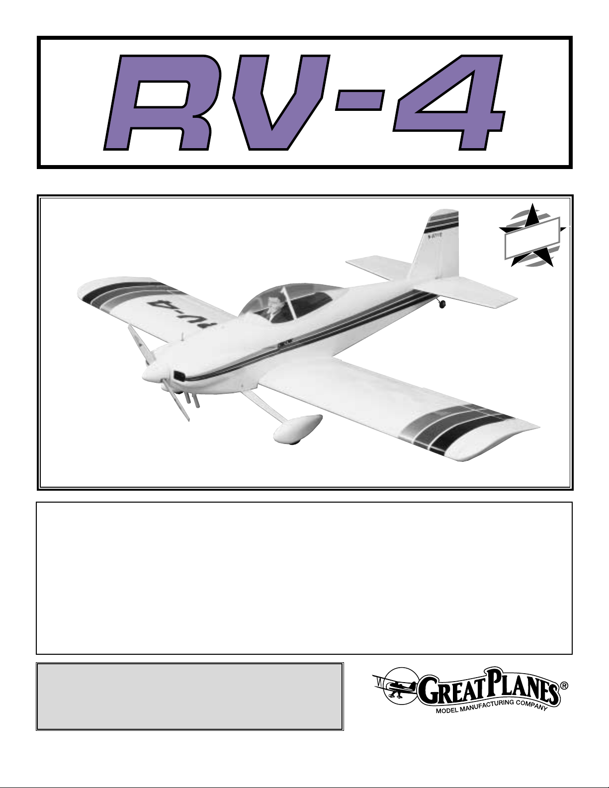
Wingspan: 54-5/8 in. (1388mm)
Wing Area: 628.8 sq. in.(40.56dm2)
Weight: 5-3/4 lbs to 6-1/4 lbs ( 2610g - 2850g)
Length: 49-5/8 in. (1260mm)
Wing Loading: 21 oz per sq ft to 22.9 oz per sq ft (64.4 grams per dm
2
- 70.3 grams per dm2)
MADE IN
USA
Page 2

INTRODUCTION . . . . . . . . . . . . . . . . . . . . . . . . . . . . . . 2
SAFETY PRECAUTIONS. . . . . . . . . . . . . . . . . . . . . . . . 2
DECISIONS YOU MUST MAKE . . . . . . . . . . . . . . . . . . . 3
Radio Equipment. . . . . . . . . . . . . . . . . . . . . . . . . . . 3
Engine Recommendations . . . . . . . . . . . . . . . . . . . . 3
ADDITIONAL ITEMS REQUIRED . . . . . . . . . . . . . . . . . 3
Hardware and Accessories . . . . . . . . . . . . . . . . . . . 3
Adhesives and Building Supplies . . . . . . . . . . . . . . . 3
Optional Supplies and Tools. . . . . . . . . . . . . . . . . . . 4
IMPORTANT BUILDING NOTES . . . . . . . . . . . . . . . . . . 4
Common Abbreviations . . . . . . . . . . . . . . . . . . . . . . 5
Types of Wood. . . . . . . . . . . . . . . . . . . . . . . . . . . . . 5
Metric Conversions . . . . . . . . . . . . . . . . . . . . . . . . . 5
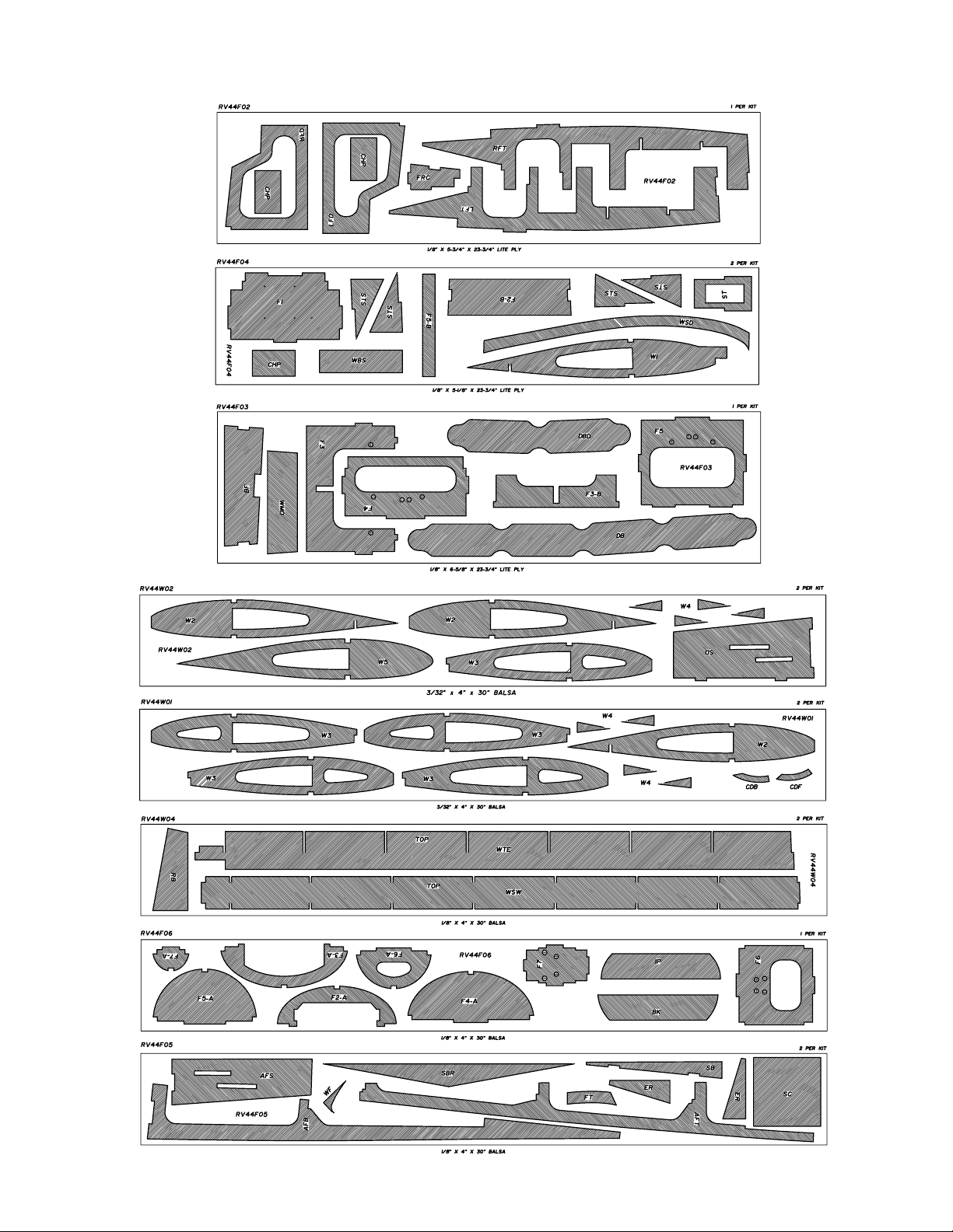
DIE-CUT PATTERNS . . . . . . . . . . . . . . . . . . . . . . . . . 5, 6
BUILD THE TAIL SURFACES. . . . . . . . . . . . . . . . . . . . . 7
Build the Stabilizer and Elevator. . . . . . . . . . . . . . . . 7
Build the Fin and Rudder . . . . . . . . . . . . . . . . . . . . . 9
BUILD THE WING . . . . . . . . . . . . . . . . . . . . . . . . . . . . 10
Build the Wing Panels . . . . . . . . . . . . . . . . . . . . . . 10
Build the Aileron and Flaps . . . . . . . . . . . . . . . . . . 17
Aileron Installation . . . . . . . . . . . . . . . . . . . . . . . . . 19
Flap Installation . . . . . . . . . . . . . . . . . . . . . . . . . . . 20
Join the Wing Halves. . . . . . . . . . . . . . . . . . . . . . . 20
BUILD THE FUSELAGE. . . . . . . . . . . . . . . . . . . . . . . . 22
Mount the Wing to the Fuselage. . . . . . . . . . . . . . . 30
Finish the Fuselage . . . . . . . . . . . . . . . . . . . . . . . . 31
Mount the Landing Gear . . . . . . . . . . . . . . . . . . . . 33
Mount the Engine. . . . . . . . . . . . . . . . . . . . . . . . . . 34
Install the Fuselage Components . . . . . . . . . . . . . . 36
Install the Fuel Tank. . . . . . . . . . . . . . . . . . . . . . . . 38
Finish the Radio Installation . . . . . . . . . . . . . . . . . . 39
Finish the Servo Installation . . . . . . . . . . . . . . . . . . 40
Assemble the Cowl . . . . . . . . . . . . . . . . . . . . . . . . 41
Assemble the Wheel Pants . . . . . . . . . . . . . . . . . . . 42
Install the Cowl . . . . . . . . . . . . . . . . . . . . . . . . . . . 42
Install the Wheel Pants. . . . . . . . . . . . . . . . . . . . . . 43
PREPARE THE MODEL FOR COVERING . . . . . . . . . . 44
BALANCE THE MODEL LATERALLY . . . . . . . . . . . . . 44
FINISH THE COCKPIT. . . . . . . . . . . . . . . . . . . . . . . . . 44
COVER THE MODEL WITH MONOKO TE®. . . . . . . . . . 44
Covering Sequence . . . . . . . . . . . . . . . . . . . . . . . . 44
Install the Stab and Fin . . . . . . . . . . . . . . . . . . . . . 45
PAINTING . . . . . . . . . . . . . . . . . . . . . . . . . . . . . . . . . . 45
JOIN THE CONTROL SURFACES . . . . . . . . . . . . . . . . 45
CANOPY INSTALLATION . . . . . . . . . . . . . . . . . . . . . . 46
GET THE MODEL READY TO FLY. . . . . . . . . . . . . . . . 46
Check the Control Directions . . . . . . . . . . . . . . . . . 46
Set the Control Throws. . . . . . . . . . . . . . . . . . . . . . 47
Balance the Model (C.G.). . . . . . . . . . . . . . . . . . . . 47
PREFLIGHT . . . . . . . . . . . . . . . . . . . . . . . . . . . . . . . . . 48
Identify Your Model. . . . . . . . . . . . . . . . . . . . . . . . . 48
Charge the Batteries . . . . . . . . . . . . . . . . . . . . . . . 48
Balance Propellers . . . . . . . . . . . . . . . . . . . . . . . . . 48
Ground Check . . . . . . . . . . . . . . . . . . . . . . . . . . . . 48
Range Check . . . . . . . . . . . . . . . . . . . . . . . . . . . . . 48
ENGINE SAFETY PRECAUTIONS. . . . . . . . . . . . . . . . 49
AMA SAFETY CODE. . . . . . . . . . . . . . . . . . . . . . . . . . 49
CHECK LIST . . . . . . . . . . . . . . . . . . . . . . . . . . . . . . . . 49
FLYING . . . . . . . . . . . . . . . . . . . . . . . . . . . . . . . . . . . . 50
Fuel Mixture Adjustments . . . . . . . . . . . . . . . . . . . . 50
Takeoff . . . . . . . . . . . . . . . . . . . . . . . . . . . . . . . . . . 50
Flight . . . . . . . . . . . . . . . . . . . . . . . . . . . . . . . . . . . 50
Landing . . . . . . . . . . . . . . . . . . . . . . . . . . . . . . . . . 51
2-VIEW DRAWING . . . . . . . . . . . . . . . . . . . . Back Cover
The RV-4 is a great flying semi-scale model that you will be
proud to take to the local flying field! This plane has great
ground handling characteristics, performs most aerobatic
maneuvers with ease and with the addition of the flap
option, crawls in very slowly on landing.Take your time and
enjoy the building process. You will be rewarded from the
very first flight!
1.Your RV-4 should not be considered as a toy, but rather a
sophisticated, working model that functions very much like a
full-size airplane.Because of its performance capabilities, the
RV-4, if not assembled and operated correctly, could possibly
cause injury to yourself or spectators and damage property.
2. You must assemble the model according to the
instructions. Do not alter or modify the model, as doing so
may result in an unsafe or unflyable model. In a few cases
the instructions may differ slightly from the photos.In those
instances the written instructions should be considered
as correct.
3.You must take time to build straight, true and strong.
4. You must use an R/C radio system that is in first-class
condition and a correctly sized engine and components (fuel
tank, wheels, etc.) throughout the building process.
5.You must properly install all R/C and other components so
that the model operates properly on the ground and in the air.
6.You must check the operation of the model before every
flight to insure that all equipment is operating and that the
model has remained structurally sound. Be sure to check
clevises or other connectors often and replace them if they
show any signs of wear or fatigue.
7. If you are not already an experienced R/C pilot, you
should fly the model only with the help of a competent,
experienced R/C pilot.
PRO TECT YOUR MODEL,Y OURSELF
& OTHERS...FOLLOW THESE
IMPORTANT SAFETY PRECAUTIONS
INTRODUCTION
TABLE OF CONTENTS
2
Page 3
Remember:Take y our time and f ollo w the instructions to
end up with a well-built model that is straight and true.
Before starting to build,compare the parts in this kit with
the Parts List and note any missing parts. Also inspect
all parts to make sure they are of acceptable quality. If
any parts are missing, broken or defective, or if you have
any questions about building or flying this airplane,
please call us at (217) 398-8970, or e-mail us at
productsupport@greatplanes.com. If you are contacting
us for replacement parts, please be sure to provide the
full kit name RV-4 and the part numbers as listed in the
Parts List.
For the latest RV-4 updates, you can also check our web
site at www
.greatplanes.com.
If you have not flown this type of model before, we
recommend that you get the assistance of an experienced
pilot in your R/C club for your first flights. If you're not a
member of a club, your local hobby shop has information
about clubs in your area whose membership includes
experienced pilots.
In addition to joining an R/C club, we strongly recommend y ou
join the AMA (Academy of Model Aeronautics). AMA
membership is required to fly at AMA sanctioned clubs.There
are over 2,500 AMA chartered clubs across the country.
Among other benefits, the AMA provides insurance to its
members who fly at sanctioned sites and events .Additionally,
training programs and instructors are available at AMA club
sites to help you get started the right way. Contact the AMA at
the address or toll-free phone number below:
Academy of Model Aeronautics
5151 East Memorial Drive
Muncie, IN 47302-9252
Tele. (800) 435-9262
Fax (765) 741-0057
or via the Internet at http://www.modelaircraft.org
This is a list of items required to finish the RV-4 that must be
purchased separately. For some of these items there is more
than one option which will require a bit of decision making
ahead of time.Order numbers (in parentheses) are provided
for your convenience.
A quality five channel (if you do not plan on flaps you can use
a four channel radio) or greater radio system. Seven servos
with an output of at least 40 ounce-inches (five servos if you
omit the flap option).T wo - 12" servo e xtensions (HCAM2100)
for the ailerons, four - 6" servo extensions (HCAM2000) for
the flaps and receiver and two “Y”connectors (HCAM250) for
the flaps and ailerons.
There are several engines that will w ork well in the R V-4.Our
official engine size recommendation range is .40 to .52 two
-stroke or .52 to .70 four-stroke. Engines such as the O.S.
®
.40 FX (OSMG0540), O.S..46 FX (OSMG0546), O.S.FS-52
(OSMG0852), O.S. FS-70 (OSMG0870), Super Tigre
®
GS.40 (SUPG0125), GS .45 ABC (SUPG0150) and the
G-.51 (SUPG0154) are all excellent choices for the RV-4. If
you select an engine in the upper end of the size range,
remember that this is supposed to be a scale model that is
intended to fly at scale-like speeds, so prudent throttle
management should be practiced.
In addition to the items listed in the “Decisions You Must
Make” section, the following is a list of hardware and
accessories required to finish the RV-4.
❏ 2 - Wheels - 2-1/2" (GPMQ4223)
❏ 1" Tail wheel (GPMQ4241)
❏ Spinner - 2-1/4"
❏ Propellers - See engine manufacturer’s recommendation
❏ Fuel line - 3' [914mm] silicone (GPMQ4131)
❏ 10 oz. Fuel tank (GPMQ4104)
In addition to common household tools (screwdrivers, drill,
etc.), this is the “short list” of the most important items
required to build the RV-4.
We recommend Great Planes
Pro™CA and Epoxy glue.
Adhesives & Building Supplies
Hardware & Accessories
ADDITIONAL ITEMS REQUIRED
Engine Recommendations
Radio Equipment
DECISIONS YOU MUST MAKE
We, as the kit manufacturer, provide you with a top
quality kit and instructions, but ultimately the quality and
flyability of your finished model depends on how you
build it; therefore, we cannot in any way guarantee the
performance of your completed model and no
representations are expressed or implied as to the
performance or safety of your completed model.
3
Page 4
4
❏ 1 oz.Thin Pro CA (GPMR6002)
❏ 4 oz. Medium Pro CA+ (GPMR6010)
❏ 6-Minute Epoxy (GPMR6045)
❏ 30-Minute Epoxy (GPMR6047)
❏ Hobby knife (HCAR0105)
❏ #11 blades (HCAR0211)
❏ Single-edge razor blades (HCAR0212)
❏ Small T-pins (HCAR5100)
❏ Builder's triangle (HCAR0480)
❏ Electric drill and 1/16" [1.6mm], 5/64" [2mm], 3/32"
[2.4mm], 1/8" [3mm], 9/64" [3.6mm], 5/32" [4mm],17/64"
[6.7mm] and 1/4" [6mm] drill bits
❏ Small Phillips and flat blade screwdrivers (HCAR1040)
❏ Wire cutter (HCAR0630)
❏ Great Planes Plan Protector (GPMR6167) or wax paper
❏ Sanding tools and sandpaper assortment (see Easy-
Touch™Bar Sander section)
❏ Sealing Iron (TOPR2100)
❏ Heat Gun (TOPR2000)
❏ Great Planes tap and drill set (GPMR8108)
❏ 2 - Rolls MonoKote®covering (See page 44)
❏ Trim sheets
Here is a list of optional tools and accessories mentioned in
the manual that will help you build the RV-4.
❏ Bisson Muffler (BISG4046)
❏ Pilot Figure (1/5th scale)
❏ Fuel Valv e (GPMQ4160)
❏ Great Planes CG Machine™(GPMR2400)
❏Top Flite Precision Magnetic Prop Balancer™(TOPQ5700)
❏ Top Flite Hot Sock™iron cover (TOPR2175)
❏ Straightedge with scale (HCAR0475)
❏ Cutting mat (HCAR0456)
❏ Masking Tape (TOPR8018)
❏ CA Debonder (GPMR6039)
❏ CA Applicator tips (GPMR6033)
❏ CA Accelerator (GPMR6034)
❏ R/C-56 Canopy Glue (JOZR5007)
❏ Epoxy Brushes (GPMR8060)
❏ Mixing Sticks (GPMR8055)
❏ Threadlocker (GPMR6060)
❏ Denatured Alcohol (for epoxy clean up)
❏ Felt-Tip Marker (TOPQ2510)
❏ Small metal file
❏ Rotary tool such as Dremel
®
❏ Rotary tool reinforced cut-off wheel (GPMR8200)
❏ Curved Tip Canopy Scissors for Trimming Plastic Par ts
(HCAR0667)
❏ Hook and Loop Material (GPMQ4480)
❏ Dead Center™Engine Mount Hole Locator (GPMR8130)
❏ Great Planes AccuThrow™Deflection Gauge (for
measuring control throws, GPMR2405)
❏ Great Planes Groove Tube™(GPMR8140)
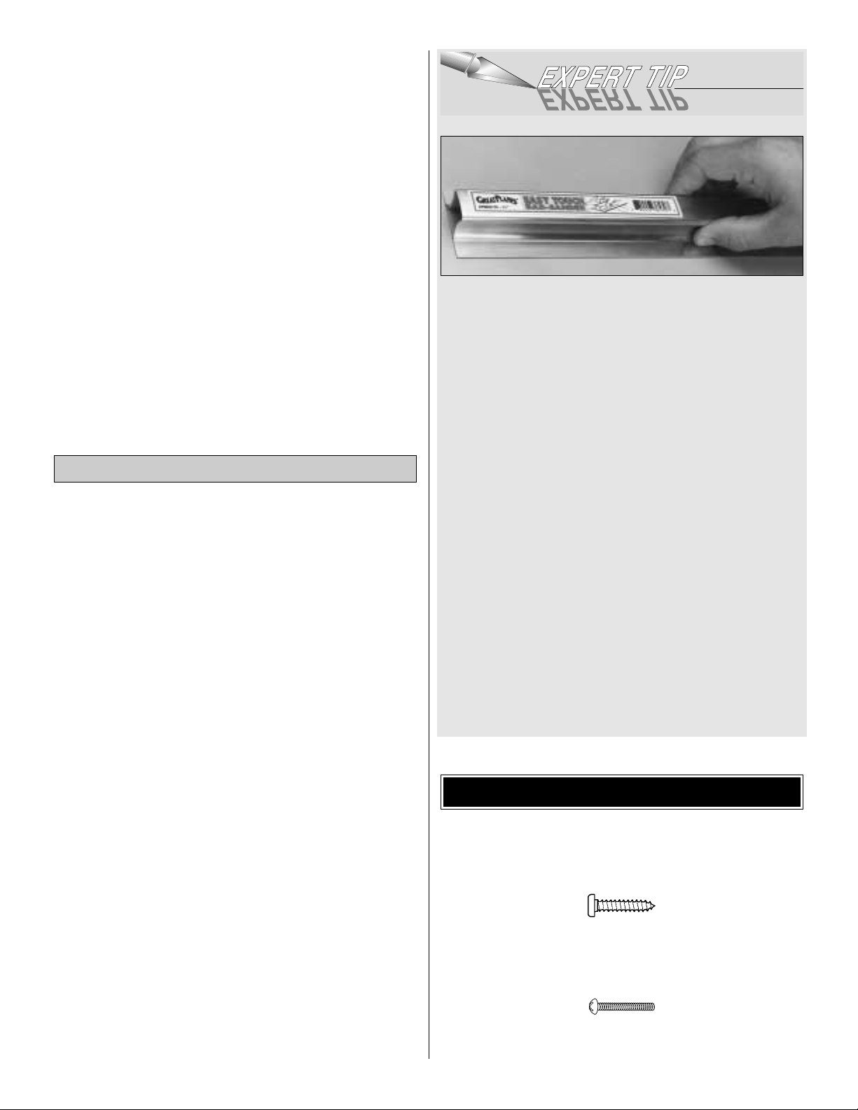
A flat, durable, easy to handle sanding tool is a necessity
for building a well finished model. Great Planes makes a
complete range of Easy-Touch™Bar Sanders and
replaceable Easy-Touch Adhesive-backed Sandpaper.
While building the RV-4, we used two 5-1/2" Bar Sanders
and two 11" Bar Sanders equipped with 80-grit and
150-grit Adhesive-backed Sandpaper.
Here's the complete list of Easy-Touch Bar Sanders and
Adhesive Backed Sandpaper:
5-1/2" Bar Sander (GPMR6169)
11" Bar Sander (GPMR6170)
22" Bar Sander (GPMR6172)
33" Bar Sander (GPMR6174)
44" Bar Sander (GPMR6176)
11" Contour Multi-Sander (GPMR6190)
12' roll of Adhesive-backed 80-g rit sandpaper (GPMR6180)
150-grit (GPMR6183)
180-grit (GPMR6184)
220-grit (GPMR6185)
Assortment pack of 5-1/2" strips (GPMR6189)
We also use Top Flite®320-grit (TOPR8030, 4 sheets) and
400-grit (TOPR8032, 4 sheets) wet-or-dry sandpaper for
finish sanding.
There are two types of screws used in this kit:
Sheet metal screws are designated by a number and a
length. For example: #6 x 3/4"
This is a number six screw that is 3/4" long.
Machine screws are designated by a number, threads per
inch and a length. For example:4-40 x 3/4"
This is a number four screw that is 3/4" long
with forty threads per inch.
IMPORTANT BUILDING NOTES
Optional Supplies & Tools
Page 5
When you see the term
test fit
in the instructions, it
means that you should first position the part on the
assembly without using any glue, then slightly modify or
custom fit
the part as necessar y for the best fit.
Whenever the term
glue
is written you should rely upon
your experience to decide what type of glue to use.When a
specific type of adhesive works best for that step the
instructions will make a recommendation.
Whenever just
epoxy
is specified you may use
either
30minute (or 45-minute) epoxy or6-minute epoxy. When 30minute epoxy is specified it is highlyrecommended that you
use only 30-minute (or 45-minute) epoxy, because you will
need the working time and/or the additional strength.
Photos and sketches are placed before the step they
refer to. Frequently you can study photos in following steps
to get another view of the same parts.
Not all die-cut parts have a name, or their complete name
stamped on them, so refer to the die drawings on page 5 and
6 for identification.When it's time to remove the parts from their
die sheets, if they are difficult to remov e, do not force them out.
Instead, use a sharp #11 blade to carefully cut the part from the
sheet, then lightly sand the edges to remove any slivers or
irregularities. Save some of the larger leftover pieces of wood.
Fuse = Fuselage
LE = Leading Edge (front)
TE = Trailing Edge (rear)
Stab = Stabilizer
" = Inches
Elev = Elevator
LG = Landing Gear
Ply = Plywood
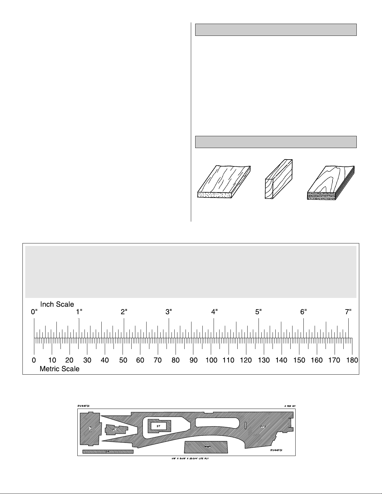
Balsa Basswood Plywood
Types of Wood
Common Abbreviations
5
Metric Conversions
1/64" = .4 mm
1/32" = .8 mm
1/16" = 1.6 mm
3/32" = 2.4 mm
1/8" = 3.2 mm
5/32" = 4.0 mm
3/16" = 4.8 mm
1/4" = 6.4 mm
3/8" = 9.5 mm
1/2" = 12.7 mm
5/8" = 15.9 mm
3/4" = 19.0 mm
1" = 25.4 mm
2" = 50.8 mm
3" = 76.2 mm
6" = 152.4 mm
12" = 304.8 mm
18" = 457.2 mm
21" = 533.4 mm
24" = 609.6 mm
30" = 762.0 mm
36" = 914.4 mm
DIE-CUT PATTERNS
Page 6
6
DIE-CUT PATTERNS
Page 7
❏ 1. Unroll the plan sheets. Roll them inside out so they will
lie flat.
❏ 2. Position the wing plan so the stab plan is over your flat
building board. Cover the plan with Great Planes Plan
Protector or wax paper so glue will not adhere.
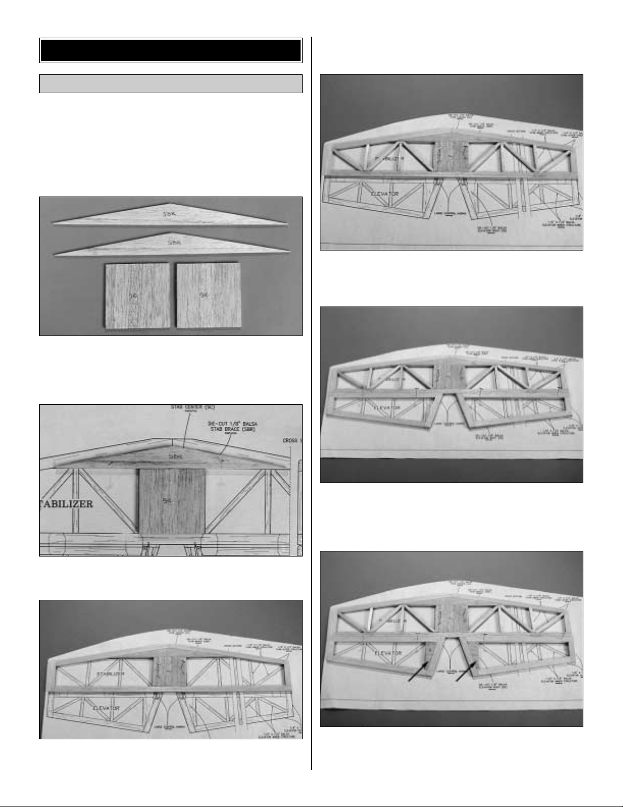
❏ 3. Locate the two die-cut 1/8" [3mm] balsa stab braces
(SBR) and two die-cut 1/8" [3mm] balsa stab centers (SC).
Glue the parts together to form the 1/4" [6mm] balsa stab
brace and the 1/4" [6mm] stab center.
❏ 4. Pin the balsa stab brace (SBR) over the plans.Glue the
stab center (SC) to the balsa stab brace (SBR).
❏ 5. Locate the 1/4" x 1/2" x 30" [6 x 13 x 750mm] balsa
sticks.Cut them to size as shown on the plan to form the stab
outer structure. Pin them to the building board over the
plans. Glue them together forming the stab outer structure.
❏ 6. Locate the 1/4" x 1/4" x 30" [6 x 6 x 750mm] balsa
sticks. Cut them to size as shown on the plan. Then glue
them in place to form the stab inner structure.
❏ 7. Cut the 1/4" x 1/2" x 30" [6 x 13 x 750mm] balsa sticks
to size as shown on the plan. Then glue them in place to
form the elevator outer structure.
❏ 8. Locate four die-cut 1/8" [3mm] balsa elevator roots (ER).
Glue them together to form two 1/4" [6mm] elev ator roots.Glue
one in place in each elevator half as shown on the plan.
Build the Stab & Elevator
BUILD THE T AIL SURF ACES
7
Page 8
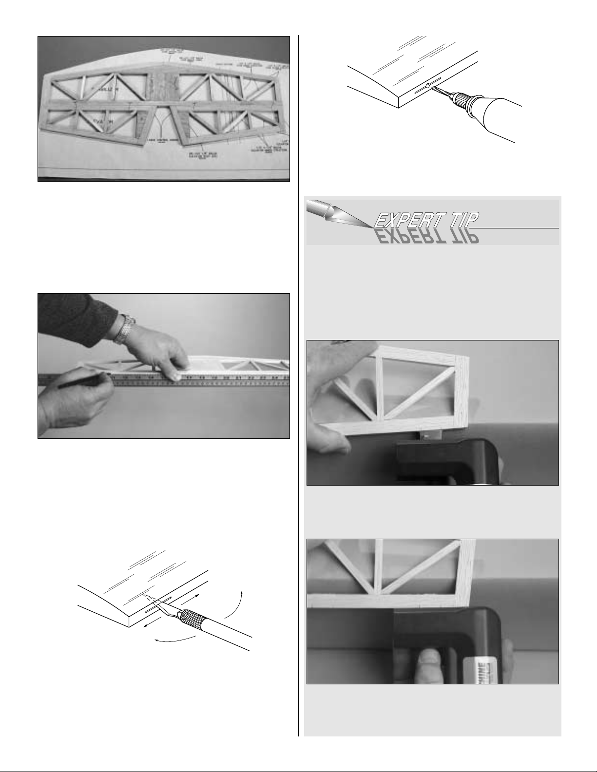
❏ 9. Cut the 1/4" x 1/4" x 30" [6 x 6 x 750mm] balsa sticks
to size as shown on the plan. Then glue them in place to
form the elevator inner structure.
❏ 10. Remove the parts from the plan. Sand the control
surfaces smooth and shape the L.E.of the stab and the T.E.
of the two elevator halves to match the cross section shown
on the plan.
Do not shape the L.E.of the two elevator halves .
❏ 11. Locate the center of the T.E. of the stab. Place a T-pin
on the center at each end of the stab. Lay a straight edge
against the pins and draw a center line on the T.E of the
stab.Repeat this procedure for each elevator half.
❏ 12. Using the plans as your reference, mark the location
for the hinges on the T.E.of the stab and the L.E. of the two
elevator halves.
❏ 13. Cut the hinge slot in the stab and elevator using a #11
blade inserted in your hobby knife .Begin by carefully cutting a
very shallow slit at the hinge location to accurately establish the
hinge slot. Make three or four more cuts, going a little deeper
each time.As you cut, slide the knife from side to side until the
slot has reached the proper depth and width for the hinge.
❏14.Drill a 3/32" [2.4mm] hole 1/2" [13mm] deep in the center
of the hinge slot. This will help the glue to better saturate the
hinge and the wood when the hinges are installed.
If you are like most modelers, cutting slots for the hinges is
time consuming and tedious. A really great time saver and
accurate tool to make this job very simple is the Great Planes
Slot Machine. This tool is available in a corded 110V AC.
(GPMR4010) as well as a cordless version (GPMR4011).
With this tool you can cut hinge slots in a matter of seconds.
1.After marking the location for the hinge, place the edge of
the cutting blade on the mark and use a little pressure to set
the teeth into the wood.
2.Squeeze the trigger on the Slot Machine and the teeth will
cut a perfectly sized width and depth for today’s CA type
hinges. Optional blades (GPMR4016) are available to cut
slots for the nylon type hinges as well.
8
DRILL A 3/32" HOLE
1/2" DEEP, IN CENTER
OF HINGE SLOT
CUT HINGE SLOT
WITH HOBBY KNIFE
AND #11 BLADE
Page 9
❏ 15. Bevel the L.E.of the elevator halves as shown on the
plan cross section.
❏ 16. Trial fit the stab, hinges and elevator halves together.
Important: Do not glue the hinges in place. This will be
done after the model has been covered.
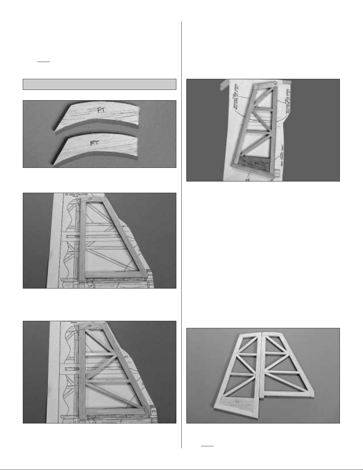
❏ 1. Locate the two die-cut 1/8" [3mm] balsa fin tops (FT).
Glue them together forming the 1/4" [6mm] balsa fin top.
❏ 2. Pin the fin top over the plan.Assemble the fin using the
1/4" x 1/2" x 30" [6 x 13 x 750mm] balsa sticks, cuttting them
to size as shown on the plan.
❏ 3. Cut the 1/4" x 1/4" x 30" [6 x 6 x 750mm] balsa sticks
to size as shown on the plan. Then glue them in place to
form the fin inner structure.
❏ 4. Locate the two die-cut 1/8" balsa rudder bases (RB).
Glue them together forming the 1/4" balsa rudder base.
❏ 5.Pin the rudder base over the plan.Construct the rudder
outer structure using the 1/4" x 1/2" x 30" [6 x 13 x 750mm]
balsa sticks. Cut them to size as shown on the plan Then
glue them in place.
❏ 6.Cut the 1/4" x 1/4" x 30" [6 x 6 x 750mm] balsa sticks to
size as shown on the plan to form the rudder inner structure.
❏ 7. Remove the parts from the plan. Sand the control
surfaces smooth and shape the L.E. of the fin and the T.E.
of the rudder to match the cross section shown on the plan.
Do not shape the L.E. of the rudder.
❏ 8. Locate a center line on the T.E. of the fin. Follow the
same procedure used for doing this on the stab and elev ator.
❏ 9. Using the plans as your reference, mark the location for
the hinges on the T.E.of the fin and the L.E. of the rudder.
❏ 10.Cut the hinge slots using the same procedure used for
the stab and elevator.
❏ 11. Bevel the L.E. of the rudder as shown on the plan
cross section.
❏ 12. Trial fit the fin, hinges and rudder halves together.
Important: Do not glue the hinges in place. This will be
done after the model has been covered.
Build the Fin & Rudder
9
Page 10
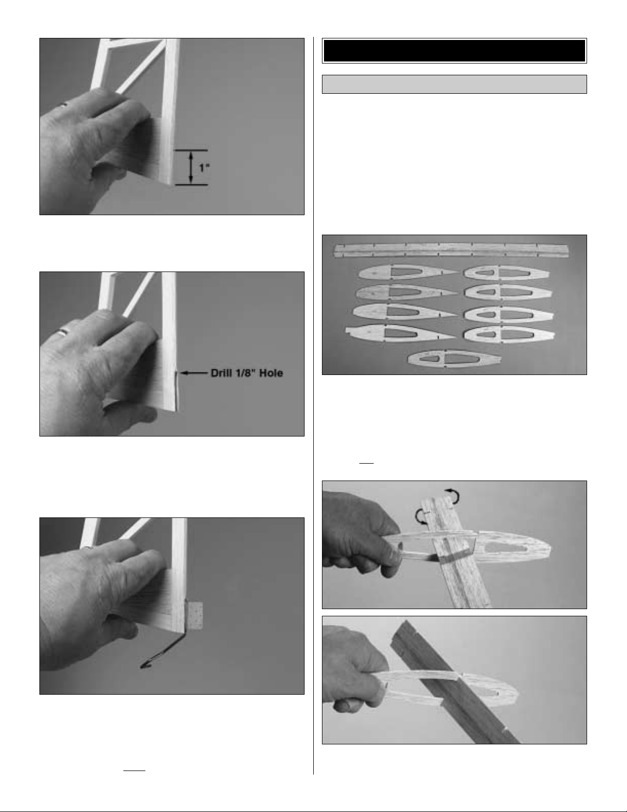
❏ 13. Remove the rudder from the fin. Measure up from the
bottom of the rudder 1" [25mm] and make a mark on the
leading edge of the rudder.
❏ 14. On the mark drill a 1/8" [3mm] hole 3/4" [19mm] deep
into the leading edge of the rudder. From the bottom of the
rudder up to the hole you have drilled, cut a groove 1/8"
[3mm] wide. Hint: A perfect tool for this is the Great Planes
Groove Tube (GPMR8140).
❏ 15. Locate the tailwheel wire assembly. Trial fit it into the
hole and slot. When you are satisfied with the fit, mark the
location for the nylon bushing on the fin.Cut a slot in the fin
to accept the bushing. Trial fit the rudder with the tailwheel
wire into the fin. Do not glue the nylon bushing in place.
This will be done after the model has been covered.
❏ 1. Unroll the plan sheets. Roll them inside out so they will
lie flat.
❏ 2. Locate the left wing panel on the plan.You may find it
helpful to cut the plans in half, making them a more
manageable size to pin to your building board.
❏ 3. Position the left wing plan flat on the building board.
Cover the plan with Great Planes Plan Protector or wax
paper so glue will not adhere to it.
❏❏4. Locate the die-cut 1/8" [3mm] balsa wing shear web
(WSW), three die-cut 3/32" [2.4mm] balsa W2 ribs, five die-cut
3/32" balsa W3 ribs and one die-cut 3/32" [2.4mm] W1 rib.
Note: In the following steps it is important to pay careful
attention to assemble the parts exactly as instructed.Failure
to do so will result in a wing that is not straight.
❏❏5.Locate the die-cut 1/8" [3mm] balsa wing shear web
(WSW). Insert the end of WSW into one of the W3 ribs.
Build the Wing Panels
BUILD THE WING
10
Page 11
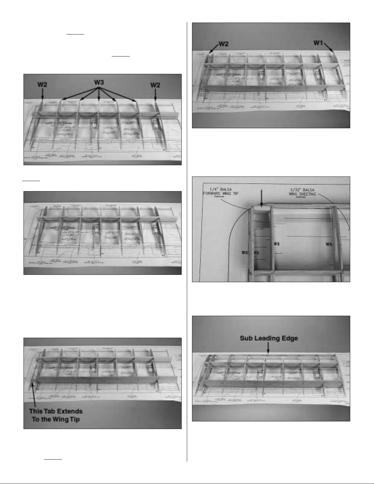
Position the rib over the third set of notches and then twist
it into the notch.Do not
glue them to each other at this time.
❏❏6. Using your plan as your guide, install the remaining
W3 ribs into the proper notches. Do not
glue them in place
at this time.
❏❏7. Install two W2 ribs at the location shown on the plan.
Do not
glue them at this time.
❏❏8. Locate two 1/8" x 1/4" x 30" [3 x 6 x 762mm]
basswood wing spars. Cut them to a length of 26-1/4"
[667mm]. Place one of the spars at the location shown on
the plan. With all of the ribs now positioned on the wing
shear web (WSW), place WSW and the ribs onto the
basswood wing spar. Then place the top wing spar into the
notches. Do not glue the assembly together at this time.
❏❏9. Locate the die-cut 1/8" [3mm] balsa wing trailing
edge (WTE). Insert it into the notches at the trailing edge of
each of the ribs. Be sure that the tab end of WTE is at the
wingtip.Do not
glue them in place at this time.
❏❏10.Position the remaining W2 rib at the wingtip and the
W1 rib at the wing root. Note: Refer to the wing root detail
cross-section for proper orientation of the W1 rib. When you
are satisfied with the fit of all of the wing components, glue
them together with thin CA.
❏❏11. Locate the 5/8" x 1/4" x 24" [15.9 x 6 x 457mm]
balsa stick. Cut a piece to fit between the two W2 ribs.This
will be the forward balsa wing tip.Glue it in place.
❏❏12.Locate the 1/16" x 1/2" x 30" [1.6 x 13 x 762mm] balsa
sub leading edge. Use a butt joint at rib W1 and then glue it
in place on the front of each of the ribs.After gluing it in place,
lightly sand the top and bottom of the sub leading edge with a
sanding bar making sure it matches the shape of the ribs.
11
Page 12
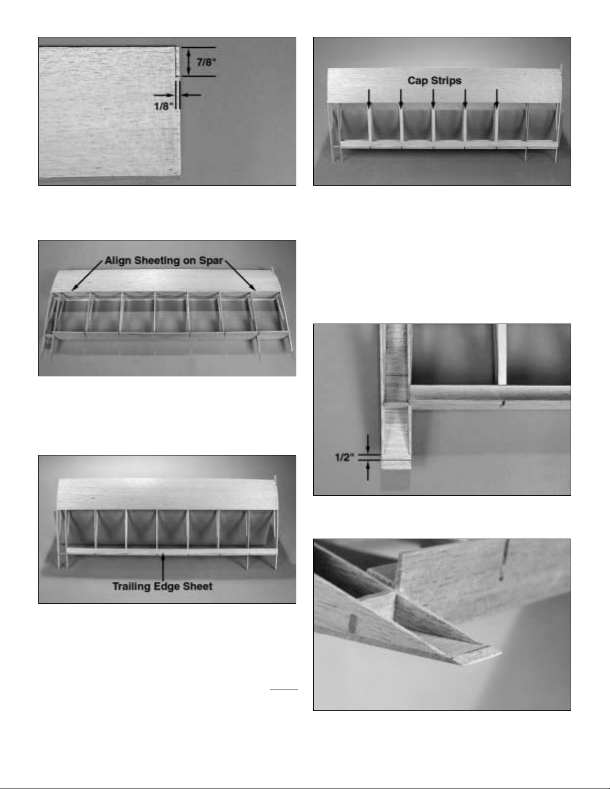
❏❏13.Locate a 3/32" x 4" x 30" [2.4 x 102 x 762mm] balsa
sheet. Cut a notch on the end of the sheet 7/8" [22.2mm]
from the L.E. and 1/8" wide.
❏❏14.Glue the 3/32" x 4" x 30" [2.4 x 102 x 762mm] balsa
sheet in place on the top of the wing. Align the sheet with
the trailing edge and on top of the wing spar when gluing it
to the wing.
❏❏15. Glue the 3/32" x 5/8" x 30" [2.4 x 15.9 x 762mm]
balsa wing trailing edge sheet in place. Now would be a
good time to add some thin CA to all joints to be sure that
everything is glued together well.
❏❏16.T urn the wing over and sheet the bottom of the wing
the same way you did the top of the wing.NOTE:You do not
need to cut the notch in the 3/32" x 4" x 30" [2.4 x 102 x
762mm] balsa sheet as you did for the top of the wing.
❏❏17.Glue the 3/32" x 5/8" x 30" [2.4 x 15.9 x 762mm] balsa
wing trailing edge sheet in place on the bottom of the wing.
❏❏18. Locate the 3/32" x 5/16" x 24" [2.4 x 7.9 x 610mm]
balsa cap strips. Cut the cap strips to fit between the
forward sheeting and the trailing edge sheeting. Use the
plan as your guide to identify the ribs that should be cap
stripped. Cap strip both the top and the bottom of the wing.
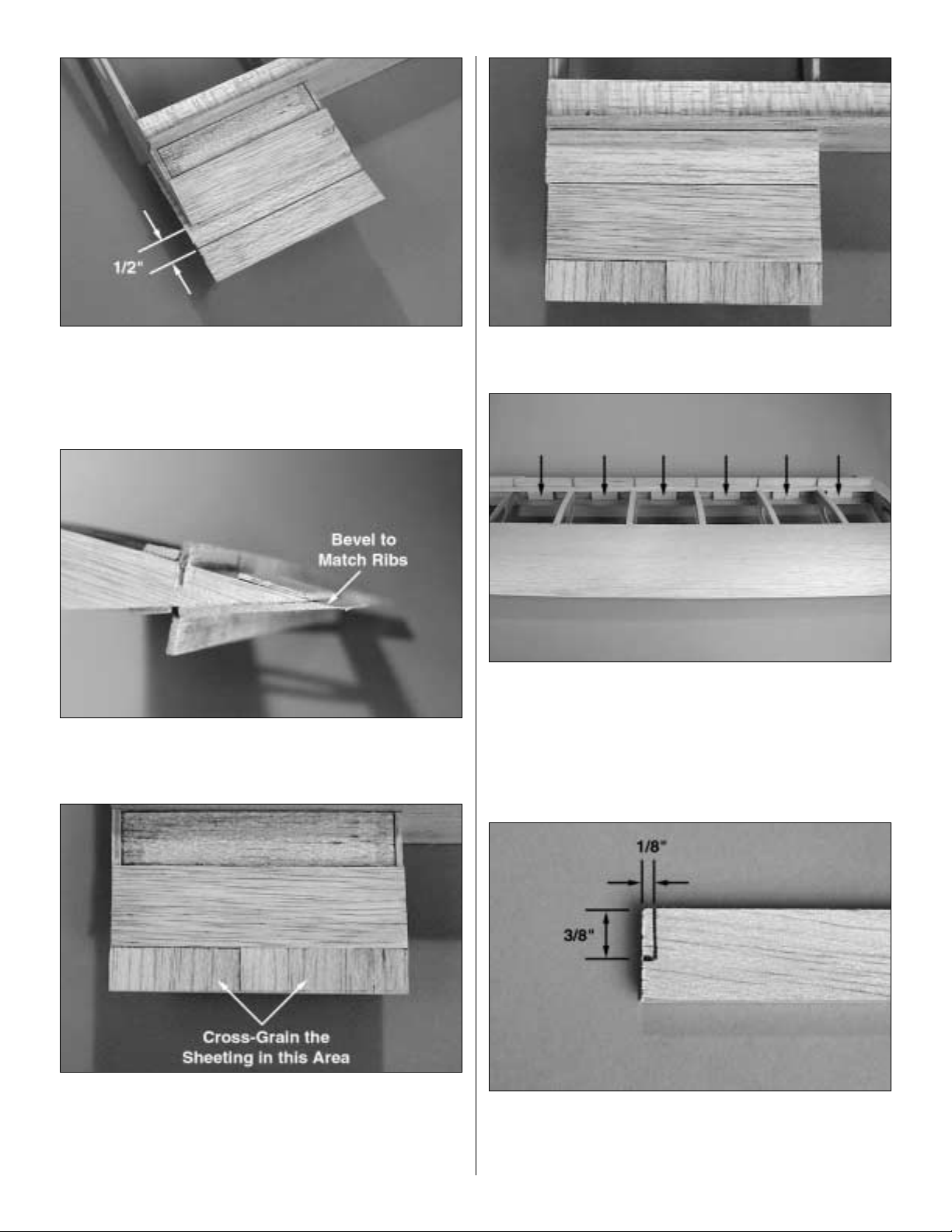
❏❏19. Sheet the bottom of the wing between the outboard
W2 ribs from leftover 3/32" x 4" x 30" [2.4 x 102 x 762mm]
balsa sheet. Extend the sheeting 3/4" [19mm] beyond the
end of the ribs.
❏❏20.After the sheeting is glued in place make a line across
the sheet, 1/2" [13mm] from the trailing edge of the W2 ribs.
❏❏21. Using a sanding bar, bevel the end of the balsa
sheeting to match the wing rib. Sand from the end of the
sheeting up to the line you drew.
12
Page 13
❏❏22.Sheet the top of the wing between the outboard W2 ribs
from leftover 3/32" x 4" x 30" [2.4 x 102 x 762mm] balsa sheet.
❏❏23. Locate the 5/8" x 1-3/4" x 7" [15.9 x 44 x 178mm]
balsa block.Cut it into two 3-1/2" [89mm] long pieces.
❏❏24. Fit one of the balsa blocks between rib W1 and W2
at the trailing edge of the rib.
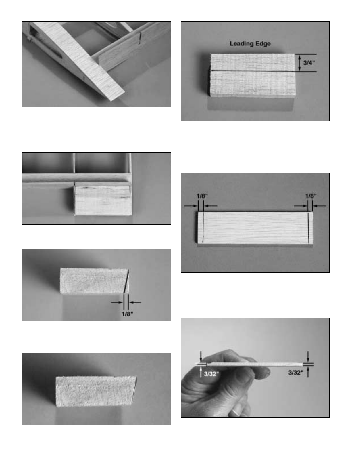
❏❏25. On the block make a mark 1/8" [3mm] from the
end. Draw a line from that mark to the corner as shown in
the photograph.
❏❏26. Sand the end of the block to the line you just made.
❏❏27. From the end of the block where you sanded the
taper into the block, measure forward 3/4" [19mm] from the
leading edge and draw a line across the block.
❏❏28.Locate the die-cut 1/8" plywood WBS. On each end
measure in 1/8" [3mm] and draw a line across WBS.
❏❏29. From the line out to the edge, sand the plywood to
a thickness of 3/32" [2.4mm].
13
Page 14

❏❏30. Glue WBS to the balsa block between the end of the
block and the line you have made on the balsa block. Position
WBS so that it extends equally ov er each end of the balsa block.
❏❏31. Trial fit WBS and the balsa block in place between
the W2 ribs at the inboard of the wing.Using a leftover piece
of 3/32" [2.4mm] sheet, lay it in place across the W2 ribs
and the balsa block. Check to be sure the sheeting and
WBS match in thickness. If WBS is slightly high, sand a bit
more from the sheeting as indicated in step 29. Note: Make
sure you work from the bottom of the wing.
❏❏32. One you are satisfied with the fit of the balsa block
and WBS, glue it in place between the W1 and W2 r ibs.
❏❏33.When the balsa block is glued in place you will see
that the block extends well beyond the W2 r ib. Use a razor
plane to shape the block to match the shape of the W2 r ib.
If you do not have a hob by r azor plane y ou can cut this bloc k
down with a long bladed knife or a sanding block. Hint: If
you do not currently own a hobby plane it really is one of the
most worthwhile tools you can own. It is wor th a trip to the
hobby shop to purchase one.
❏❏34. Sheet the top of the wing between W1 and W2.
Sheet the area from the wing trailing edge (WTE) to 1"
[25mm] beyond the end of the ribs.
14
Page 15
❏❏35. Turn the wing over on the bench so that you are
looking at the bottom of the wing. From the end of each of
the ribs measure back 1/2" [13mm] and draw a line across
the sheeting. Cut the sheeting on this line.
❏❏36. Using a sanding bar, bevel the sheeting to match
the ribs.
❏❏37. From leftover 3/32" [2.4mm] balsa sheeting, apply
balsa onto the upper wing skin from the root of the wing up
to WBS.When applying the balsa sheet it must be installed
cross grain. This will provide much more strength to the
trailing edge of the wing.
❏❏38. Sheet the area between WTE and WBS, gluing
3/32" [2.4mm] balsa sheet to the balsa block.
❏❏39. Locate the 5/8" x 1/4" x 18" [15.9 x 6 x 457mm]
balsa stick that is used for the CA hinge blocks. From the
18" stick cut six blocks 1-1/2" [38mm] long.Glue each of the
blocks in place inside the wing on the backside of the wing
trailing edge. Refer to your plan for the proper placement of
each of the blocks.
❏❏40. Locate the 1/4" x 3/4" x 30" [6 x 19 x 762mm] balsa
leading edge. On one end make a line 1/8" [3mm] from the
end, extending 3/8" [9mm] from the edge of the leading
edge. Cut this area away.
15
Page 16
❏❏41. Fit the leading edge in place on the balsa sub
leading edge.The notch you just cut from the leading edge
should fit around the tab extending from W1. Once you are
satisfied with the fit, glue the leading edge to the balsa sub
leading edge on the front of the wing.
❏❏42. Trim the ends of the leading edge to be flush with
the ends of the wing.
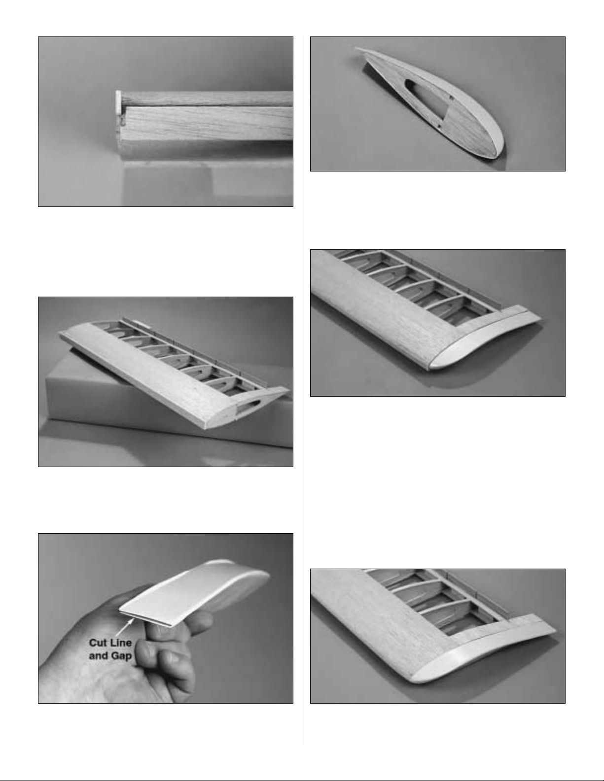
❏❏43. Locate the left ABS plastic wing tip. Trim it on the
cut lines.When cutting the trailing edge of the wig tip there
is a cut between the top and bottom of the wingtip.
❏❏44. Locate rib W5 and insert it into the plastic wing tip.
Position the rib to be flush with the end of the wing tip then
glue it in place with thin CA.At the trailing edge of the plastic
wing tip, the top and bottom of the plastic wing tip will need
to be glued together with thin CA.
❏❏45. Place the wing tip onto the end of the wing. The
notches in W5 should fit onto the wing spars that are
extending from the wing. Important: You now need to make
a decision on how you wish to do the final installation of the
wing tip.Y ou can permanently glue the wing tip in place on the
end of the wing or you can tack glue it in place by applying a
drop of CA to a few spots on the wing tip and the wing.If you
choose to tack glue the wing tip in place it can be removed,
making it easier to apply your covering. This will also allow
you to paint the wing tip without it being attached to the wing.
After the covering is applied and the wing tip is painted, you
can permanently glue the wing tip in position. Either way will
work.The choice is left to your personal preference.
❏❏46. Sand the leading edge of the wing to shape as
shown on the wing cross section of your plan.Sand the wing
top and bottom to match the ABS wing tip.
16
Page 17

❏❏1. Locate a 3/32" x 4" x 24" [2.4 x 102 x 610mm] balsa
sheet. Cut it into two pieces 2" wide and cut each piece to a
length of 21-3/16" [537.8mm]. These will become the top
and bottom aileron/flap sheeting.
❏❏2. Using the plan as your guide, mark the location of
each of the W4 ribs onto one of the aileron/flap sheets.
❏❏3. On one edge of the sheeting, draw a line the length
of the sheeting, 1/8" [3mm] from the edge of the sheet.
❏❏4. Locate the wing plan. On the wing plan there is a
pattern of the W4 ribs with the top of the rib being shown on
this drawing.Find the die-cut ribs and mark each of the ribs
with a “T” to indicate the top of the rib.
❏❏5. Glue eight W4 ribs onto the marks you have made
on the sheeting. The front edge of each W4 rib should be
placed on the line, 1/8" [3mm] from the edge of the sheeting.
Be sure that each of the ribs is glued onto the sheeting with
the top of the ribs perpendicular to the sheeting as shown in
the photograph.
❏❏6. Locate the 1/8" x 1/2" x 24" [3 x 13 x 610mm] balsa
aileron/flap sub leading edge. Position this on the lower
skin and against the front of each of the W4 ribs.Glue them
in place with thin CA.
❏❏7. Sand the balsa aileron / flap sub leading edge with a
sanding bar to match the shape of the W4 ribs.
Build the Ailerons & Flaps
17
Page 18

❏❏8. Draw a line the length of the aileron/flap 1/4" [6mm]
from the trailing edge of the sheeting.
❏❏9. Bevel the sheeting to match the top of the W4 ribs.
When sanded properly the bevel should meet the line you
have just drawn.
❏❏10. Locate two die-cut 1/8" [3mm] plywood control
horn plates (CHP). Glue one in the flap and one in the
aileron at the location shown on the plan.
❏❏11. Use a T-pin and punch two holes through the
flap/aileron skin between the two W4 ribs.This will identify
where to cut the flap and aileron apart in a later step.
❏❏12. Glue the remaining 3/32" x 2" x 21-3/16" [2.4 x 10²
[537.8mm] balsa aileron / flap sheeting to the top of the
aileron/flap.
❏❏13. Locate the 1/4" x 3/4" x 24" [6 x 19 x 610mm] balsa
aileron/flap leading edge. Glue it in place on the front of
the aileron/flap sub leading edge.
❏❏14. Tur n the aileron/flap over. Mark a line through the
pin holes that you pierced through the skin.
❏❏15. Cut the aileron and flap apart by cutting on the line
you have drawn. Now would be a good time to mark which
one is the flap and which is the aileron. Be sure to indicate
which is the top and bottom of each control surface.
Referencing the control surfaces will eliminate confusion
and insure that you install the aileron and flap properly so
that the control horn plates are located on the bottom of the
control surfaces.
❏❏16. Sand the top and bottom of the flap and aileron,
making the leading edge match the control surfaces.
18
Page 19

❏❏17. Cut off the top and bottom of the wing trailing edge
that extends abov e and below the surface of the wing. Sand
the wing trailing edge to match the wing surface.
❏❏1. Mark a center line the length of the aileron.
❏❏2.Using the plan as your guide, mark the location of the
hinges on the center line of the aileron.
❏❏3. Shape the leading edge of the aileron to match the
shape shown on the aileron cross section on the plan.
❏❏4. Draw a center line on the trailing edge of the wing
where the aileron will be installed. Place the aileron in
position at the trailing edge of the wing making sure that you
leave at least 1/16" [1.6mm] clearance between the end of
the aileron and the outboard end of the wing. Transfer the
location of the hinge slots from the aileron to the trailing
edge of the wing.
❏❏5. Refer to your plans for the location of the aileron
control horn. The aileron cross - section shows where the
clevis needs to be positioned in relation to the hinge line.
Mark the location for the mounting screws. Drill 1/16"
[1.6mm] pilot holes in the aileron.Important: When you drill
the holes you should be drilling into the plywood control
horn plate.If you do not hit the plate check to make sure you
are drilling into the bottom of the aileron which is where the
plate is located. Attach the control horn with two #2 x 3/8"
[9.5mm] sheet metal screws.
Aileron Installation
19
Page 20

You now have to decide if you want to build the wing with or
without the flap option. If you decide to build it with the flap
you will need two additional standard 40 oz. servos and a
5th channel available on your radio system. The use of flaps
allows the plane to fly markedly slower than without the flap
option.This allows you to fly slower, land slo wer and tak e-off
in a much shorter distance. If you have a computer radio
with flap to elevator mixing you can also program the plane
to do very tight loops with flap elevator coupling.
If you are not installing operational flaps proceed with the
next two steps.If you are installing operational flaps proceed
to step 3.
NON-FUNCTIONAL FLAP INSTALLATION
❏❏1. Glue the flap leading edge to the wing trailing edge
and the root rib of the flap to the rib W2.
❏❏2. Sand the flap to match the contour of the top and
bottom of the wing.
FUNCTIONAL FLAP INSTALLATION
❏❏3. Mark the location for the flap hinges on the wing
trailing edge and the leading edge of the flap.The slot for the
hinge needs to be 1/16" from the bottom of the wing. Do not
mark the hinge location on a centerline.
❏❏4. Cut the slots for the hinges using the same
procedure used for the aileron except the slot needs to be
cut into the wing and the flap at an angle as shown.
❏❏5.T rial fit the aileron and flap with the hinges to the wing
making sure that you have at least a 1/16" [1.6mm]
clearance between the control surfaces.
❏❏6. Attach the control horn to the bottom of the flap
following the same procedure used for mounting the control
horn to the elevator.
❏ 7. This completes the construction of the left wing panel.
The sheeting and servo trays that have not yet been
installed will be completed after the two wing halves are
joined together. Go back and repeat the wing assembly
procedure for the right wing panel.
❏ 1. Locate the die-cut 1/8" [3mm] plywood dihedral brace
(DB) and dihedral brace doubler (DBD). Use 6-minute
epoxy to glue the dihedral brace doubler to the dihedral
brace, centering the doubler on the brace.
Join the Wing Halves
Flap Installation
20
1/16"
Hinge Slot
Page 21

❏ 2. Trial fit the dihedral brace into the wing by inserting it
into the left wing panel and then twisting it into position
between the wing spars.
❏ 3. Slide and twist the right wing panel onto the other end
of the dihedral brace to check the fit of the two wing panels.
❏ 4. When you are satisfied with the fit, glue the dihedral
brace to both wing panels with 30 minute epoxy. Be sure to
apply glue to the root ribs of both wing panels as well.Clamp
the entire wing assembly together and allow the glue to cure.
❏ 5. Now that the wing panels have been joined, use the
leftover 3/32" x 4" x 24" [2.4 x 102 x 610mm] balsa sheeting
to sheet the top and bottom center section of the wing.
❏ 6. At the location shown on the plans, cut two 1/2" [13mm]
holes in the top of the wing for the aileron and flap servo leads
to exit the wing.
❏ 7. Locate the die-cut 1/8" [3mm] plywood servo tray
support (STS) and the die-cut 1/8" [3mm] plywood servo
tray (ST).
❏ 8. Assemble the servo tray as shown. If you are using
flaps in your model you will need to assemble four servo
trays.If you are only going to have ailerons on your airplane
you will need to assemble two.
21
Page 22

❏ 9. Working from the bottom of the wing, trial fit the aileron
servo trays in place at the location on the plan. When you
are satisfied with the fit, glue it in place to the rib and the
wing shear web (WSW).
Note:If you did not choose to install the flaps,skip step 10.
❏ 10. Trial fit the flap servo trays in place at the location on
the plan.When you are satisfied with the fit, glue it in place
to the rib and the wing shear web (WSW).
❏ 11. Glue left over 1/8" [3mm] balsa stick around the two
sides of the trays.This will give you a surface to attach the
covering to when you finish the model.
❏ 12. Use a sanding bar to do the final sanding of the wing.
❏ 13.This completes the construction of the wing. Take the
time to get your bench cleaned up so you can get started on
the fuselage!
❏ 1. Locate the two die-cut 1/8" [3mm] plywood forward
fuselage sides (FFS). At the front of FFS there is a notch
with two additional slits.
❏ 2. On
one
FFS only, draw a line from the end of each slit.
❏ 3. Using a hobby knife, cut on the line. This will provide
you with one FFS that has a deeper notch than the other.
BUILD THE FUSELAGE
22
Page 23

❏ 4. The forward fuselage side (FFS) with the deeper notch
is the right side of the fuselage. This is important!
Somewhere on the part mark “right” to make sure that there
is no confusion as you proceed to the next few steps. The
deeper notch on the right side of the fuselage is what builds
in the right thrust so it is important to install the left and right
side correctly.
❏ 5. Unroll the plan sheets. Roll them inside out so they will
lie flat.
❏ 6. Locate the fuselage on the plan.You may find it helpful
to cut the plans and separate the fuselage side view from
the fuselage top view, making them a more manageable
size to pin to your building board.
❏ 7. Position the fuselage side view on the building board.
Cover the plan with Great Planes Plan Protector or wax
paper so glue will not adhere to it.
❏❏8.Pin the left forward fuselage side (FFS) over the plan.
(Remember, the left side is the one that has the shallow
notch cut into the front.)
❏❏9. Locate two 1/8" x 3/8" x 24" [3 x9.5 x 610mm] balsa
sticks. These make up the fuselage side. Glue them in
place at the rear of the forward fuselage side (FFS).
❏❏10.Glue the die-cut 1/8" [3mm] balsa aft fuselage side
(AFS) to the balsa sticks at the rear of the fuselage as
shown on the plan. Cut the balsa sticks flush with AFS.
❏❏11.Locate the 3/32" [2.4mm] die-cut balsa stab doubler
(SD). Glue it in place onto the balsa aft fuselage side (AFS),
aligning it with the bottom and rear of the fuselage side.
❏ 12. Repeat steps 8 - 10 for the right fuselage side.
Remember, the right side mirrors the left side of the fuselage.
Be sure not to build two left fuselage sides!
23
Page 24

❏ 13. Locate the die-cut 1/8" [3mm] plywood forward right
fuselage top (RFT) and the forward left fuselage top
(LFT). Glue RFT and LFT together as shown.
❏ 14. Locate the two die-cut 1/8" [3mm] plywood aft
fuselage tops (AFT).Glue them together the same way you
did the forward right and left fuselage top.
❏ 15. Glue the forward fuselage top to the aft fuselage top
as shown.This forms the fuselage top and will be referred to
as the fuselage top throughout the construction process.
❏ 16. Locate the two die-cut 1/8" [3mm] balsa aft fuselage
bottoms (AFB). Glue them together the same way as the
fuselage tops.
❏ 17. Pin the fuselage top over the plans. Important! The
fuselage will be assembled on the plans upside down.When
you are assembling components that reference the right or
left side of the fuselage, take the time to be sure you are
working with the correct side of the fuselage.
❏ 18. On the inside of the left and right side of the fuselage
glue the die-cut 1/8" [3mm] plywood wing saddle doubler
(WSD) in place as shown on the plan.
❏ 19. Locate die-cut 1/8" [3mm] plywood formers F3, F4
and F5 as well as die-cut 1/8" [3mm] balsa formers F6 and
F7. Test fit formers F3 through F7 onto the fuselage top at
the location shown on the plans.When you are satisfied with
the fit, glue the formers in place to the fuselage top. Use a
small modeling square to assure that the formers are
perpendicular to the fuselage top.
❏ 20. Glue the right side of the fuselage to the fuselage top.
When completed, glue the left side in place.
❏ 21. Locate the die-cut 1/8" [3mm] plywood left fuselage
doubler (LFD) and the right fuselage doubler (RFD).
24
Page 25

❏ 22. Glue the right fuselage doubler (RFD) to the inside of
the right fuselage side between F1 and F3.
❏ 23. Glue the left fuselage doubler (LFD) to the inside of
the left fuselage side between F1 and F3.
❏ 24. Glue the aft fuselage bottom in place at the rear of the
fuselage. It should fit into the notches at F5 - F7.
❏ 25. Locate the die-cut 1/8" [3mm] plywood bottom
firewall (BF) and F2-B.
❏ 26. Sand a 45 degree bevel on the top and bottom of F2-B.
❏ 27. Glue the die-cut 1/8" [3mm] plywood bottom firewall
(BF) to the fuselage sides at the front of the fuselage.After BF
is in place, glue F2-B to the fuselage sides and the top of BF.
❏ 28. Locate the die-cut 1/8" [3mm] plywood F3-B doubler.
Glue it in place onto F3, fitting it into the notches between
LFD and RFD.
❏ 29. Locate the 1/4" x 2-3/4" x 5-1/2" [6 x 64 x 140mm]
birch plywood landing gear mount. Cut the landing gear
plate to fit at the location shown on the plan between F3, the
firewall and the fuselage sides.Glue the plate in place using
30-minute epoxy.
❏ 30. Locate the two die-cut 1/8" [3mm] plywood F1 firewalls.
Glue the two F1's together to form one 1/4" [6mm] firewall.
25
Page 26

❏ 31. Dr ill a 5/32" [4mm] through each of the punch marks
on the firewall.
❏ 32. Remove the fuselage from the plan and turn it over.
Test fit the firewall to the fuselage.The firewall needs to be
90 degrees to the fuselage top.If it is not, sand the fuselage
to adjust until the firewall is 90 degrees to the fuselage top.
When you are satisfied with the fit, apply a small drop of
medium CA to the flange of each of the 6-32 blind nuts,
being careful not to get any of the glue into the threads.
Then insert the 6-32 blind nuts into the holes you have
drilled on the backside of the firewall.
❏ 33.Using 30-minute epoxy, glue the firewall in place to the
fuselage sides, the fuselage top and the bottom firewall
(BF). Use a small builders square and check again to be
sure that the firewall is 90 degrees to the fuselage top once
the firewall is glued into place.
❏ 34. Cut off the fuselage side that extends beyond the
firewall and sand the sides flush with the firewall.
❏ 35. Glue the 1/8" [3mm] die-cut plywood F5B to F5 as
shown on the plan.
❏ 36. Locate the two die-cut 1/8" [3mm] plywood wing
mounting plates (WMP). Glue them together to form one
1/4" [6mm] plate.
26
Page 27

❏ 37. From for mer F5B measure forward 1/2" [13mm] and
make a mark on each side of the fuselage. With 6-minute
epoxy glue the wing mounting plate to the fuselage sides,
over the wing saddle doubler at the the mark you made.
❏ 38.Locate the die-cut 1/8" [3mm] plywood wing mounting
plate doubler (WMD). Glue the wing mounting plate doubler
to the wing mounting plate with 6-minute epoxy.
❏ 39. Locate two die-cut 1/8" [3mm] balsa stab braces
(SB). Glue them together to form the stab brace.
❏ 40. Turn the fuselage over and glue the stab brace in
place on top of the fuselage at the aft of the fuselage.
❏ 41. Sand the fuselage sides flush with the stab brace.
27
Page 28

❏ 42. Locate the die-cut 1/8" [3mm] balsa formers F7A,
F6A, F5A, F4A F3A and F2A. Glue them in place at the
location and angles as shown on the plan.
❏ 43. Locate the die-cut 1/8" [3mm] plywood fuel tank right
cover (FRC) and fuel tank left cover (FLC). Glue the fuel
tank right cover into the notches in F2A and F1A on the right
side of the fuselage and glue the fuel tank left cover into the
notches in F2A and F1A on the left side of the fuselage.
❏ 44. From a leftover piece of 1/8" [3mm] plywood, cut a
piece 1/2" x 3" [13 x 76mm]. Draw a center line across the
length of this piece.
❏ 45. Locate the die-cut 1/8" [3mm] plywood fuel tank top
cover (FTC). Trial fit the fuel tank cover into the notches in
FRC, FLC and the firewall.When satisfied with the fit, remove
FTC and glue the 1/8" x 1/2" x 3" [3 x 13 x 76mm] plywood
piece (from the previous step) to the bottom of the fuel tank
cover using the line as the reference for gluing it to FTC.
❏ 46. Place FTC back into the notches in FRC, FLC and the
firewall. The tab that you have glued to the botom of FTC
should fit under the opening in F2-A.
❏ 47.When you are satisfied with the fit make a mark on the
center of the tab on the front of FTC and center it over the
1/4" [6mm] firewall. Drill a 1/16" [1.6mm] hole on this mark
through FTC and the firewall. Hold the FTC in place with a
#2 x 5/8" [15.9mm] sheet metal screw and a #2 washer.
❏ 48.Locate the 1/8" x 1/4" x 24" [3 x 6 x 610mm] basswood
turtledeck stringer. Cut it to fit on top of formers F2A
through F4A.Cut the remaining piece to fit on top of formers
F5A through F7A.
28
Page 29

❏ 49. Locate the 1/8" x 1/8" x 24" [3 x 3 x 610mm] balsa stick.
Glue it in place on top of the basswood turtledeck stringer,
making sure that it is glued in the center of the turtledeck
stringer.Do this for both the front and rear turtledeck stringer.
❏ 50. Locate three 3/16" x 3/16" x 30" [4.8 x 4.8 x 762mm]
balsa sticks.Cut them to fit at the base of the turtledeck on both
the front and rear turtledeck on both sides of the fuselage.
❏ 51. On the fuselage plan is the turtledeck sheeting
template.From a 3/32" x 4" x 24" [2.4 x 102 x 610mm] balsa
sheet, cut two turtledeck sheets.
❏ 52. Sheet the turtledeck with the sheets you cut.This is a
fairly tight bend so we recommend that you soak one side of
the wood with water or isopropyl alcohol, allowing the balsa
to soften and become more flexible. When the balsa is
sufficiently softened, glue the sheeting to F5-A, F6-A, F7-A
and the turtledeck stringers. After the wood has dried, sand
the turtledeck to match the fuselage sides and the balsa
turtledeck stringer to match the shape of the tur tledeck.
❏53. From the remaining 3/32" x 4" x 24" [2.4 x 102 x 610mm]
balsa sheet, cut the deck sheeting for the front of the airplane.
Locate the deck patterns on the plan and use them to make
the sheets.
❏ 54.Glue the forward deck sheeting between F2A and F3A
and the deck stringers.Glue the rear deck sheeting between
F3A and F4A and the deck stringers. Sand the sheeting to
match the fuselage sides and sand the balsa deck stringers
to match the deck sheeting.
❏ 55. From leftover 3/16" [4.8mm] square balsa stick, cut
four sticks to fit between the 3/16" [4.8mm] turtledeck
stringers as shown in the photograph.
❏ 56. Locate the 1/16" x 3" x 18" balsa sheet. Cut the sheet
in half and edge glue the sheets together forming a 6" wide
sheet.Cut the sheet to fit in the cockpit of the plane, making
sure the sheet fits on top of the 3/16" [4.8mm] balsa sticks
and balsa turtledeck stringers. Glue the sheeting to the
balsa sticks.
29
Page 30

❏ 1.Turn the fuselage upside down.
(Hint: Position a small
box under the cockpit to support the plane on your bench.)
Install the wing onto the wing saddle.
❏ 2. Measure from the tip of the tail to a point on the end of
the wing. The distance from the tip of the wing to the tail
needs to be equal on both sides.Once the wing is positioned
properly , make ref erence marks on the wing and the fuselage.
❏ 3.With the wing still resting in the wing saddle and aligned
on the marks you have made, mark the location to drill the
wing bolt holes. From the outer end of the wing bolt plate
measure in 2" [51mm] and draw a line.Measure up from the
side of the wing bolt plate 1/2" [13mm] and draw another
line.Where the two lines intersect is where you will drill the
wing bolt holes.
❏ 4. At the intersection of the lines on the wing bolt support,
drill a 9/64" [3.6mm] (or use a #25 drill bit) pilot hole
perpendicular to the bottom of the wing, through the wing
and the wing bolt mounting plate in the fuselage.
❏ 5. Remove the wing. Tap the holes in the wing bolt
mounting plate with a 1/4-20 tap. After they have been
tapped, apply a small amount of thin CA to the threads.
Once the glue has cured run the tap through the threads
once more to clean out any excess glue.
❏ 6. Enlarge the wing bolt holes in the wing by drilling a
17/64" [6.7mm] hole through the 9/64" [3.6mm] holes you
drilled in Step 4. This will provide clearance for the nylon
wing bolts. Be sure you only drill the hole in the wing, not
the wing bolt mounting plate.
❏ 7. Attach the wing to the fuselage with the nylon wing
mounting bolts, checking to be sure the wing fits well.
❏ 8. Locate two die-cut 1/8" [3mm] balsa wing fairings
(WF). Glue them to the leading edge of the wing flush with
the top of the fuselage. Remove the wing.
Mount the Wing to the Fuselage
30
AA
A = A
Page 31

❏ 9. From left over 3/32" [2.4mm] balsa sheet cut a piece to
fit between the two wing fairings and a piece to fill the front
of the fairing at the leading edge of the wing. Glue them in
place.Then sand the wing fairing to blend into the wing.
❏ 1. Locate the 3/32" [2.4mm] die-cut balsa cockpit
doublers (2- CDB and 2-CDF). Note: Doublers CDF are
shorter than CDB.
❏ 2. Glue the CDF doublers to F4A. Be sure to set them
back from the edge of the fuselage 3/32" [2.4mm], the width
of the fuselage sheeting. When positioned properly they
should fit the outer edge of F4A.
❏ 3. Glue the CDB doublers to F5A.Position them the same
way as you did for CDF.
❏ 4. Using your plan as the reference, mark the location of
BK and IP by drawing lines across the floor of the cockpit.
❏ 5. Locate die-cut 1/8" [3mm] balsa formers IP (instrument
panel) and BK (back seat). Glue former BK on the forward
most line on the cockpit floor and glue IP on the rearward line.
❏ 6. On the plan you will find the paper cockpit sheeting
template. Use this as the pattern and cut two cockpit sides
from 3/32" x 4" x 24" [2.4 x 102 x 610mm] balsa sheet.
❏❏7. Trial fit the cockpit sides to one side of the fuselage
between F4A and F5A. Sand the cockpit sheeting as
needed to fit. Once you are satisfied with the fit, glue the
cockpit sides to F4A, F5A, IP and BK.
Hint: You may need
to wet the balsa wood to bend it without cracking.
❏ 8. Repeat step 7 for the opposite side of the cockpit.
Finish the Fuselage
31
Page 32

❏ 9.From leftover 3/32" [2.4mm] balsa sheet, cut a piece to
fit on top of BK and IP as shown.
❏ 10. Attach the wing to the fuselage. Place the stab in
place on the stab base at the back of the fuselage. Stand
back 9' to 15' [3 to 5m] and view the airplane from the rear.
The distance between the wing and the stab must be equal
on both sides of the stab. If the stab is not in line with the
wing, sand the high side of the stab base until the wing and
stab are aligned with each other. Remove the wing when
everything is aligned.
❏ 11. From the 1/4" x 1/2" x 6" [6 x 63 x 152mm] balsa stab
block, make a plate that is the same siz e as the stab saddle.
When you have it done, draw a line down the center of the
stab plate.
❏ 12. Glue an additional 1/4" x 3/4" [6 x 19mm] balsa stick
to the base centered on the line you have drawn.The stick
needs to be perpendicular to the base. Sand the top of the
stick to match the rear turtledeck.
❏ 13. Set this fixture in place on the stab base.
❏ 14. Locate the 3/4" x 3/4" x 12" [19 x 19 x 305mm] balsa
block.Cut it into two 6" [152mm] lengths.Glue the end of the
block to fuselage former F7A. IMPORTANT!
Glue only the
end of the balsa blocks to F7A.Do not glue the balsa blocks
to the fixture! The fixture will be remov ed later and it m ust be
able to slide out from under the blocks.
32
Page 33

❏ 15. Using a razor plane and sanding block, shape the
balsa blocks to match the fuselage.
❏ 16. Remove the fixture you've made to be sure that it
slides out of the fuselage freely and that no glue is holding
it in place.The slots in the blocks will now fit the stab and fin
when we install them later in the manual.
❏ 17. Put the fixture back into the slots. Wrap masking tape
around the tail to keep the fixture in place. This will help
prevent accidentally knocking the shaped blocks out of
place before gluing the stab and fin in place.
❏ 1. Mark a line down the center of the landing gear plate.
❏ 2. Measure 1-1/4" forward from fuselage former F3 and
mark a line perpendicular to the line you have drawn.
❏ 3. Place the aluminum landing gear so the center hole is
at the intersection of the two lines.Make sure that the landing
gear is parallel to former F3.
Mount the Landing Gear
33
Page 34

❏ 4. Use a pen to mark the location of each of the three
landing gear mounting holes.
❏ 5. Drill a 5/32" [4mm] hole through each of the locations
you marked on the landing gear plate.
❏ 6. Locate three 6/32 blind nuts.Apply a drop of medium CA
on the flange, being careful not to get any glue onto the
threads. Then press them into the holes from inside the
fuselage. Position the landing gear over the mounting holes.
Insert a 6-32 x 3/4" [19mm] socket head cap screw and #6
washer through the landing gear and into the blind nut.Tighten
the screw against the landing gear, pulling the blind nut into
place tightly to the underside of the landing gear plate.Do this
for each of the three landing gear mounting screws.
❏ 1. Cut the “spreader bars” from the supplied Great Planes
motor mount, then use a hobby knife to remove any flashing
leftover from the molding process so the halves fit together w ell.
❏ 2. Draw an angled line from the corner of each of the
engine mounting holes across the firewall. Where the lines
intersect is the center of the engine mount. At the point the
lines intersect draw a vertical line. From the point the lines
intersect draw a horizontal line 1/4" [6mm] abov e and below
the center as shown in the photograph. These points are
where you will drill two holes for the fuel line to pass through
the firewall.
Mount the Engine
34
Page 35

❏ 3. Dr ill a 17/64" [6.7mm] hole on each of the two marks
you have made on the firewall. These holes will
accommodate the fuel line and the pressure line. Note: A
two line fuel system will require the use of a fueling valve.
We mounted ours to the firewall in the cowl opening. If you
prefer to have a third line for the fill line you will have to drill
a third hole in the firewall.
❏ 4. Attach the engine mount to the firewall. Insert a
6-32 x 1" [25mm] socket head cap screw and #6 w asher into
each corner of the engine mount, screwing the screw into
each of the four blind nuts that were previously installed on
the back side of the firewall but do not overtighten.
Note:The engine installation is a side mount so be sure that
engine mount is installed for a side mount installation.
❏ 5. Place the fuselage into a cradle or set it up on the
bench so that you can place the engine onto the engine
mount. Position the engine so that the distance from the
firewall to the front of the thrust washer is 4-1/2" [115mm]
and that the engine mount is centered on the firewall.When
satisfied with the positioning tighten the engine mounting
bolts to the firewall.
❏ 6.Mark the location for the holes for mounting the engine to
the engine mount. Hint: The Great Planes Dead Center™Tool
(GPMR8130) works fast and easy for marking these holes!
❏ 7. On the marks you made on the engine mount, drill a
7/64" [2.8mm] hole into the engine mount. After dr illing the
hole, tap each hole with a 6-32 tap.Once tapped, mount the
engine to the engine mount with four 6-32 x 3/4" [19mm]
socket head cap screws and #6 washers.
35
Page 36

❏ 8. Remove the engine from the firewall. Mix 1/4 ounce of
6-minute epoxy. Using an epoxy brush, apply a coating of
epoxy to the entire firewall and the area under the firewall
where the engine muffler will exit the cowl.Do not get any glue
into the threads of the blind nuts.A dab of V aseline®applied into
the threads of the blind nut will prev ent an y epoxy from sticking
to the threads.You may want to remove the fuel tank cover so
that it does not get glued in place. If you chose to leave it in
place you may need to cut the glue to remove the hatch cover.
❏ 1. Locate three 36" [914mm] plastic flexible outer
pushrod tubes. Using the plan as your guide, install the
outer pushrods into the holes in fuselage formers, exiting the
slots in the rear of the fuselage.
❏ 2. Make a mark on the tubes where they contact the
fuselage and fuselage formers. Remove the tubes. Then
roughen the tubes with sandpaper at the marks you have
made. Reinstall the outer pushrods tubes back into the
fuselage and use a small amount of 6-minute epoxy to glue
the tubes to the fuselage formers.
❏ 3. Cut the tubes at an angle where they exit the fuselage.
Fill the slots where the tubes exit the fuselage with a 50/50
mix of 6-minute epoxy and micro balloons.The addition of
the micro balloons thickens the epoxy, preventing it from
running and making it sand easier. Do this for both the left
and right side of the fuselage.
❏ 4.After the epoxy is fully cured, use a sanding bar to sand
the pushrod exits flush with the fuselage on both sides of
the fuselage.
❏ 5. Refer to your plan for the proper position of the elev ator
control horns. Position the control horn on the bottom of
Install the Fuselage Components
36
Correct Incorrect
Page 37

the elevator. Using a felt tip pen, mark the drilling locations
for the screws.Drill a 1/16" [1.6mm] hole through the marks.
Attach a control horn to one of the elevator halves by
inserting two 2-56 x 5/8" [15.9mm] machine screws through
the control horn and elevator, attaching it to the nylon
control horn plate. Do this for both elevator halves.
❏ 6. Install a control horn to the right side of the rudder
following the same procedure used for the elevator.
❏ 7. Locate two die-cut 1/8" [3mm] plywood servo rails
(SR). Glue them into the ser vo bay in the fuselage at the
location shown on the plan.
❏ 8. From a leftover piece of the 36" [914mm] plastic flexib le
outer pushrod, cut a piece to a length of 5-3/4" [146mm] and
install it through the remaining hole in the firewall and former
F3 for the throttle pushrod. Mark where the tube contacts
the firewall and former, roughen that area with sandpaper,
and then glue the tube in position.
❏ 9. Following the radio manufacturer’s instructions for
mounting servos, install three servos onto the servo
mounting rails at the locations shown on the plan.Center the
servos.Then, position the servo arm as shown in the photo.
❏10. Locate two 2-56 x 36" [914mm] wire pushrods.Cut one
to a length of 30-1/2" [775mm] and the other to a length of 271/2" [699mm]. Insert the wires into the two elevator outer
pushrods. (The threaded end should be at the rear of the
fuselage.) The longer wire should be in the tube on the left side
of the fuselage, the shorter on the right as shown in the photo.
❏11.Bend the shorter wire at the locations shown in the photo.
❏ 12. Locate two 5/32" [4mm] wheel collars and two
6-32 x 1/2" [13mm] socket head cap screws. Install the
screws into the wheel collars. Slide both wheel collars over
the two elevator pushrods .Do not tighten the set screws yet.
37
Page 38

❏ 13. On the threaded end of both elevator pushrods attach
a clevis retainer and then a clevis by turning it onto the
threaded end approximately 25 turns.
❏ 14. In the “Finishing the Fuselage” section of the manual
you made a balsa fixture to help in shaping the tail block. If
you followed our recommendations you did not install the
stab/elevator and fin/rudder to the fuselage. If you have not
installed them, temporarily remove the fixture and then slide
the stab/elevator and fin/rudder into the slots.
Do not glue
them in place.
❏ 15. Snap the clevis onto the bottom hole of the control
horn on each elevator half. Position both halves of the
elevator at neutral. Once they are set, tighten both set
screws in the wheel collars onto the two pushrod wires.
❏ 16. Cut another 2-56 x 36" [914mm] wire pushrod to a
length of 31-1/2" [800mm] for the rudder. Attach the clevis
and clevis retainer in the same wa y you installed them on the
elevator.Then, install the clevis onto the rudder control horn.
❏ 17. Enlarge the end hole in the servo arm of the elevator
and rudder servo with a 1/16" [1.6mm] drill bit. Position the
elevator to be neutral.Then, make a mark on the pushrod
wire with a felt tip pen where it meets the end hole in the
servo arm.
❏ 18. Position the rudder to be neutral.Then, make a mark
on the rudder pushrod wire with a felt tip pen where it meets
the end hole in the servo arm.
❏ 19. Make a 90 degree bend on the mark for both wire
pushrods. Cut off any pushrod wire extending above
the FasLink.
❏ 20. Inser t the wire through the hole in the ser vo arm and
retain it with a nylon FasLink.
❏ 21. Remove the stab and fin from the fuse. Put the fixture
in place at the rear of the fuse.
❏ 22. Following the radio manufacturer’s instructions, install
the radio switch harness on the side of the fuselage.
❏ 23.Referring to this sketch and the plan, install the receiver
and battery pack into the front lower half of the fuselage.
Connect all of the servos and servo extensions for the flaps
and ailerons, following the radio manufacturer’s instructions.
❏ 1. We are now going to break away from the radio
installation to install the fuel tank. As you can see in the
previous sketch, the foam wrapped receiver and battery are
going to support the fuel tank. Assemble the components of
the fuel tank as shown.
Install the Fuel Tank
38
Receiver &
Battery
GP
10oz (800cc)
Vent Line to
Muffler
FasLink
Servo Horn
2-56 (.074") Pushrod Wire
Page 39

❏ 2. Now is the time to decide if you are going to fill the tank
through a fuel filling valve or whether y ou are going to use a
third line as a fill line. If you choose to use a fill valve, insert
two 12" [305mm] lengths of silicone fuel tubing through the
holes in the firewall. Pull the tubing into the radio
compartment of the fuselage. If you are going to use a third
line for filling, drill 1/16" [1.6mm] hole in the center of the
third nipple on the fuel tank. Clean any debris from inside of
the tank. Then inser t three 12" [305mm] lengths of silicone
fuel tubing through the holes in the firewall.Attach the lines
to the fuel tank following the instructions with the fuel tank.
❏3.Remove the fuel tank top cover from the engine mount bo x.
This will assist you as you install the fuel tank.Pull the tank into
the fuselage by pulling on the fuel lines where they e xit from the
firewall.Position the tank against the firewall b y reaching into the
top of the engine mount box. Re-install the engine. Attach the
vent line to the muffler and the fuel pickup to the carb uretor .The
lines from the fuel tank should be just long enough to reach the
carburetor and the muffler. Cut the lines as needed. When
everything is positioned, re-attach the fuel tank cover.
❏ 1. Locate the 2-56 x 12" [305mm] wire pushrod. Cut it to a
length of 10-1/2" [267mm]. On the threaded end of the
pushrod attach a clevis retainer and clevis by tur ning it onto
the threaded end approximately 25 turns. Slide the wire into
the outer pushrod tube in the firewall.Attach the clevis to the
throttle arm and slide the clevis retainer in place on the clevis.
❏ 2. Install the brass Screw Lock Set onto the end hole of
the servo arm of the throttle servo. Assemble it as shown in
this sketch.
❏ 3. Slide the throttle pushrod into the screw lock set on the
servo arm.Turn on the transmitter and receiv er .Advance the
throttle servo to the full throttle position.Open the carburetor
on the engine to the fully opened position Tighten the set
screw on the screw lock set onto the throttle pushrod wire.
Turn the radio system off when finished.
Finish the Radio Installation
39
RETAINER
Page 40

❏❏1. Install a servo into the aileron ser vo bay in the right
wing following the radio manufacturer’s instructions. Center
the servo, then install a servo arm onto the servo.The servo
arm should be installed 90 degrees to the servo case and
the arm should be pointing toward the wingtip. Enlarge the
end hole in the servo arm of the elevator and rudder servo
with a 1/16" [1.6mm] drill bit.
❏❏2. Place a straight edge at the end hole in the servo
arm. Make a mark on the aileron in line with the end hole in
the servo arm. Important: If you have had the ailerons off
and on the wing it would be a good idea to check to make
sure that you are working with the correct aileron.Press a Tpin into the balsa skin of the aileron at the mark you have
just made. You should feel the pin push into the plywood
control horn plate. If you do not feel the plywood plate you
either have the wrong aileron or you have installed it upside
down. Do not proceed to the next step until the aileron is
correctly installed.
❏❏3. On the mark on the aileron install the aileron control
horn. Position the control horn so that it is centered on the
mark you made on the aileron.Using a felt tip pen, mark the
drilling locations for the screws. Dr ill a 1/16" [1.6mm] hole
through the marks. Saturate the holes with thin CA. After it
has cured, attach the control horn to the aileron with two #2
x 5/8" [15.9mm] sheet metal screws.
❏❏4. Locate a 2-56 x 12" [305mm] wire pushrod. Cut the
pushrod to a length of 4-3/4" [121mm].On the threaded end
of the pushrod attach a clevis retainer and clevis by tur ning
it onto the threaded end approximately 25 turns.
❏❏5. Attach the clevis to the control horn. Then, slide the
clevis retainer in position on the clevis. Center the aileron,
and then make a mark on the wire pushrod where it meets
the outer hole in the servo arm. Make a 90 degree bend in
the wire on the mark you have made.
❏❏6. Inser t the wire into the servo horn and retain it in
place with a nylon FasLink.
Finish the Servo Installation
40
Correct Incorrect
Page 41

Skip steps 7-11 If you did not install functional flaps.
❏❏7.Install a servo into the flap servo bay in the right wing
following the radio manufacturer’s instructions. Temporarily
plug the flap servo into the receiver and then turn on the
radio and transmitter .Activate the switch that will be used for
the flaps so that the servo is in the position for the flaps
retracted. Install a servo arm onto the servo.The ser vo arm
should be installed at approximately 45 degrees to the servo
case and the arm should be pointing toward the center of
the wing. Enlarge the end hole in the servo arm of the
elevator and rudder servo with a 1/16" [1.6mm] drill bit.
❏❏8. Locate a 2-56 x 12" [305mm] wire pushrod. Cut the
pushrod to a length of 4-3/4" [121mm].On the threaded end
of the pushrod attach a clevis retainer and clevis by tur ning
it onto the threaded end approximately 25 turns.
❏❏9. Attach the clevis to the control horn. Then, slide the
clevis retainer in position on the clevis. Center the aileron
and make a mark on the wire pushrod where it meets the
outer hole in the servo arm. Make a 90 degree bend in the
wire on the mark you have made.
❏❏10. Insert the wire into the ser vo horn and retain it in
place with a nylon FasLink.
❏❏11. Attach a 6" [152mm] servo extension to the flap
servo. Apply a piece of heat shrink tubing or tape to the
connectors to be sure they cannot pull apart.
❏❏12.Attach a 12" [305mm] servo extension to the aileron
servo. Apply a piece of heat shrink tubing or tape to the
connectors to be sure they cannot pull apart.
❏❏13.Route each of the leads through the wing.The leads
should exit the wing through the hole in the top of the wing
center section.
❏ 14. Repeat steps 1 -14 for the left wing panel.
❏ 15.The leads for the flap and ailerons need to be connected
together with a “Y”harness. (If you are using an 8 or 9 channel
radio you may have the ability to plug each of the lines into
separate channels in your receiver. See the radio instruction
manual before deciding which way you will proceed.)
❏ 1. Cut out the two halves of the ABS cowl. Cut the cowl
halves on the cut lines. When cut properly there will be
interlocking tabs to glue the sides of the two halves together .
❏ 2. Glue the two halves of the cowl together with medium
CA.Work on one side first, applying glue to a small section
at a time.Use CA accelerator sparingly or not at all as it can
cause the ABS plastic to get brittle. Work your way around
the cowl until it is completely glued together.Use pieces of
leftover ABS plastic to reinforce the cowl in the front.
❏ 3. Apply a plastic filler such as Bondo®to fill the seam where
the cowl halves are joined.After the filler has cured, sand the
seam until the two cowl halves blend smoothly together.
Assemble the Cowl
41
Page 42

❏ 4. Cut the openings in the front of the cowl.Wet sand the
entire cowl with 400-grit wet or dry sandpaper.The cowl is
now ready to be primed.
❏❏1.Cut out the left and right half of the wheel pants along
the cut line molded in the pants.When cut properly there will
be interlocking tabs to glue the two halves together.
❏❏2. Glue the two halves of the pants together with
medium CA. Work a small section at a time. Use CA
accelerator sparingly or not at all as it can cause the ABS
plastic to get brittle. Work your way around the wheel pant
until it is completely glued together.
❏❏3.Use a filler like you did with the cowl to fill the seam.After
the filler has cured, sand the seam with 400 grit wet or dry
sandpaper until the wheel pant halves blend smoothly together .
❏❏4. Cut the opening in the bottom of the wheel pant for
the wheel.
❏ 5. Repeat steps 1-4 for the remaining wheel pant.
❏ 1. When you installed the engine we showed the engine
with the stock muffler .The Bisson Custom Muffler, Pitts style
for the O .S. .40 - .46FX (BISG4046) is an alternative muffler
you may consider if you would like to hide most of the
muffler inside of the cowl.Before making the cut-outs in the
cowl for the engine and muffler you need to decide which
muffler you are going to use.
❏2.Mark an arc on the cowl similar to the sketch.Cut away the
cowl on the arc you hav e made.This is a good starting point for
cutting some clearance for the landing gear and muffler.
❏ 3. Remove the muffler from the engine. Slide the cowl
over the engine onto the front of the fuselage.
Install the Cowl
Assemble the Wheel Pants
42
Page 43

❏ 4. Position the cowling so that there is approximately
3/32" [2.4mm] between the back of the spinner plate and the
front of the cowl.
❏ 5. Mark the position for the cowl on the fuselage. Dr ill three
1/16" mounting holes in the cowl and into the fuselage.One hole
should be located in the top of the cowl.The other two should
be drilled on the side at the bottom of the fuselage.Remove the
cowl and drill a 3/32" [2.4mm] clearance hole through the three
mounting holes your drilled in the cowl. Do not drill clearance
holes in the fuselage. Apply a drop of thin CA into each of the
mounting holes in the fuselage.This will harden the wood, giving
a stronger surface for the screws. Mount the cowling to the
fuselage with three #2 x 5/8" [15.9mm] sheet metal screws.
❏ 6. Cut holes in the cowling to provide access to the
muffler, glow plug and the needle valve for the engine you
have installed.
❏❏1.Place a wheel pant onto a leg of the landing gear.Be
sure you match the slot on one side of the wheel pant to the
leg of the landing gear.Using a felt tip pen, mark the location
for the wheel axle onto the wheel pant.
❏❏2. Drill a 5/32" [4mm] hole through the mar k you have
made on the inside of the wheel pant.Drill through this mark
and through the outer side of the wheel pant.
❏❏3. Locate a 6/32 x 1-1/4" [32mm] socket head cap
screw, four #6 washers and two 6-32 nuts. These are the
axle assembly. Install the wheel and wheel pant onto the
axle assembly and then onto the landing gear following the
sketch above.
❏ 4. Repeat steps 1-3 for the other wheel pant.
Install the Wheel Pants
43
6-32 Nuts
6-32 x 1-1/4"
#6 Washer
#6 Washers
Page 44

❏ 1. Inspect all surfaces for uneven glue joints and seams
that require filler. Apply filler where needed. Many small
dents or scratches can be repaired by applying a few drops
of water or moistening the area with a wet tissue. This will
swell the wood, allowing you to sand it smooth after the
balsa wood has dried.
❏ 2. Sand the entire model with progressively finer grits of
sandpaper, finishing with 320 or 400-grit sandpaper.
❏ 3. Use a Top Flite Tack Cloth to remo v e sanding dust from
the model.
❏ 1. Mount your wing to the fuselage. Temporarily remove
the stab and fin fixture from the rear of the fuselage and
temporarily insert the stab and fin into the slots.
❏ 2. With the wing level, carefully lift the model by the
engine propeller shaft and the aft end of the fuselage at the
bottom of the fin trailing edge (this may require two people).
Do this several times.
❏ 3. If one wing always drops when you lift the model, that
side is heavy. Balance the airplane by gluing weight inside
the other wing tip. Glue the weight in place with epoxy. An
airplane that has been balanced laterally will track better in
loops and other maneuvers.
❏ 4. Remove the stab and fin.Then, reinstall the fixture in
the rear of the fuselage.
❏ 1. Now is the time to finish the cockpit area. We painted
our entire cockpit with flat black paint, then installed the
instrument panel decal. We also chose to install a pilot
and a rollover bar. Should you decide to install the rollover
bar refer to the drawing on the plan.This can be made from
the two 5/16" x 4-1/2" [7.9 x 115mm] wood dowels.
It is assumed that you have already co vered a couple of models
in the past, so we won't go into many details on covering
techniques, but here are some tips you should consider.
1. NEVER CUT THE COVERING DIRECTLY ON THE
SHEETING.The RV-4 depends on the sheeting for some of
its strength. Modelers who cut through the covering tend to
cut the sheeting and this will weaken the structure.
2. Use a Top Flite Hot Sock™to minimize dents in the wood
from your covering iron.
3.When you cover large sheeted surfaces such as the wing,
bond the covering in the middle and work outward, pushing
out air as you proceed. Do not move the iron in a circular
motion, but move it span-wise with the grain of the wood.
4.When you cover smaller parts with square edges such as
the elevators and ailerons , co v er the ends first with separ ate
pieces of covering. Then, all you have to do is wrap the
covering around the top and bottom and iron it down.
5.When you cover sharp junctions like where the stab meets
the fuse, cut narrow strips of covering and apply them in the
corners before you cover the major surfaces. The larger
pieces of covering will overlap the smaller pieces. This
technique also eliminates the need to cut the covering after
it has been applied.
6. If you want to duplicate the trim scheme pictured on the
box, you will need the following: 2 rolls of MonoKote White
(TOPQ0204), 1 roll of MonoKote Black (TOPQ0208), 1 roll
of MonoKote Royal Blue (TOPQ0221) and 1 roll MonoKote
Aluminum (TOPQ0205).Trim Sheets will also work well over
the white base color.
FUSELAGE
❏ 1.Tail
junctions strips
as described previously.
❏ 2. Stab tops, then bottoms.
❏ 3. Fin right, then left side.
❏ 4. Fuse bottom aft, then front.
❏ 5. Fuse sides.
❏ 6.Turtle deck (may be done in one or two pieces).
❏ 7. Front deck (aft of cowl).
WING
❏ 1. Hidden areas and corners such as the trailing edge on
the flap and aileron area.
❏ 2. Bottom of one, then the other half of the wing.
❏ 3.Top of one, then the other half of the wing.
Covering Sequence
CO VER THE MODEL
WITH MONOKOTE
®
FINISH THE COCKPIT
BALANCE THE MODEL LATERALLY
PREP ARE THE MODEL
FOR COVERING
44
Page 45

CONTROL SURFACES AND DETAILS
❏ 1.Ends, bottoms, then tops of elevators , ailerons and flaps.
❏ 2. One, then the other side of the rudder.
Once you have the stab, fin and fuselage covered you can
permanently install the stab and fin to the fuselage.
❏ 1. Mount the wing to the fuselage. Then, insert the stab
into the slots in the fuselage.Measure the distance from the
tip of the stab to the tip of the wing on the right side of the
fuselage. Measure the same point on the left side of the
fuselage.Adjust the stab until both sides measure the same.
❏ 2. If you covered the center section of the stab, mark the
outline of the fuselage on the stab with a felt tip marker.
Then, cut away the covering in the center section so that
you can achieve a good glue joint between the balsa stab
center section and the stab base on the fuselage. When
cutting the covering away be careful not to cut the balsa
wood. Cutting the balsa wood can weaken the structure!
❏ 3. Glue the stab to the fuselage with 6-minute epoxy,
checking the distance from the stab to the wing before the
glue cures.
❏ 4. After the glue has cured on the stab, insert the fin into
the slots in the fuselage.Mark the outline of the fuselage onto
both sides of the fin. Remove the fin and cut the covering,
being careful not to cut into the balsa wood structure.
❏ 5. Be sure the fin is 90 degrees to the stab.Then, glue the
fin to the fuselage with 6-minute epoxy.
At this stage all of your plastic pieces should have the
seams filled with Bondo or putty. If you haven't already done
so, wet sand the plastic parts with 400-grit wet-or-dry
sandpaper so the paint will adhere. Spray the cowling and
wheel pants with at least one coat of Top Flite LustreKote
®
primer. Wet sand the the plastic parts between coats with
400-grit sandpaper. Use Great Planes 1/8" [3mm] EZ-Mask
Flexible Masking Tape (GPMR1000) for masking sharp
lines.A Top Flite Tack Cloth (TOPR2185) is useful to remove
dust before you paint. LustreKote paint gives a matching
finish to your MonoKote finish.
After the control surfaces are cov ered, you can permanently
install the hinges into the control surfaces.
❏ 1. Start with the stab and elevators.Remove a small strip
of covering from the hinge slot.
❏ 2. Fit the hinges in the stab and elevator (without glue).
❏ 3. Join the elevators to the stab with the hinges. If the
hinges do not remain centered as you join the elevators to
the stab, remove the stab and inser t a pin in the center of
the hinge to keep them centered. Make sure there is
approximately a 1/64" [.4mm] gap between the elevators
and the stab so you do not glue them together.
JOIN THE CONTROL SURFA CES
PAINTING
Install the Stab and Fin
45
B
B = B
B
CUT THE COVERING
AWAY FROM THE SLOT
90˚
90˚
Page 46

❏4.Add six drops of thin CA to the center of the hinges on both
the top and bottom.The holes you drilled in the hinge slot will
wick the CA into the entire hinge surface.Use a paper towel to
absorb excess CA from the hinge gap before it cures.
❏ 5. Use the same hinging method to join the rudder to the
fin, the ailerons to the wing and the flaps to the wing.
❏ 6. Reinstall the pushrods you disconnected before
covering and mount the control horns to the ailerons, flaps,
elevator and rudder. Reinstall any hardware and other
components you may not already have in place such as the
fuel valve, fuel lines, ser vos, on/off switch, etc.
❏ 1. Cut the canopy on the cut line. Position the canopy in
place on the top of the fuselage after the covering of the
fuselage is complete.
❏ 2.When you are satisfied with the fit, apply a small bead of
Z-56 canopy glue to the bottom of the canopy where it comes
in contact with the fuselage. (We recommend this glue
because it dries virtually clear.) Hold the canopy in place with
masking tape until the glue is fully cured (overnight).
❏ 1. Turn on the transmitter and receiver and center the
trims. If necessary, remove the ser vo arms from the ser vos
and reposition them so they are centered. Reinstall the
screws that hold on the servo arms.
❏ 2. With the transmitter and receiver still on, check all the
control surfaces to see if they are centered.If necessary, adjust
the clevises on the pushrods to center the control surfaces.
❏ 3. Make certain that the control surfaces and the
carburetor respond in the correct direction as shown in the
diagram.If any of the controls respond in the wrong direction,
use the servo reversing in the transmitter to reverse the
servos connected to those controls. Be cer tain the control
surfaces have remained centered. Adjust if necessary.
Check the Control Directions
GET THE MODEL READY TO FLY
CANOPY INSTALLATION
Do not use CA accelerator on any of the hinges and do
not glue the hinges with anything but thin CA. Do not
attempt to glue one half of the hinge at a time. The
hinges will not be properly secured and could come out
while the model is in flight.
46
ASSEMBLE, THEN APPLY 6 DROPS
OF THIN CA TO CENTER
OF HINGE, ON BOTH SIDES
THE CA WICKS
ALONG THE "TUNNELS"
TO THE ENTIRE
HINGE SURFACE
4-CHANNEL RADIO SETUP
(STANDARD MODE 2)
ELEVATOR MOVES UP
4-CHANNEL
TRANSMITTER
RIGHT AILERON MOVES UP
LEFT AILERON MOVES DOWN
4-CHANNEL
TRANSMITTER
RUDDER MOVES RIGHT
4-CHANNEL
TRANSMITTER
CARBURETOR WIDE OPEN
4-CHANNEL
TRANSMITTER
Page 47

Use a Great Planes AccuThrow™(or a ruler) to accurately
measure and set the control throw of each control surface as
indicated in the chart that follows.If your radio does not hav e
dual rates, we recommend setting the throws at the low rate
setting for the first flights. NOTE: The throws are measured
at the widest part of the elevators, rudder and ailerons.
At this stage the model should be in ready-to-fly condition
with all of the systems in place including the engine, landing
gear, cover ing and paint and the radio system.
❏ 1.Use a felt-tip pen or 1/8" [3mm] - wide tape to accurately
mark the C.G.on the bottom of the wing on both sides of the
fuselage.The C.G. is located 3-3/4" [95mm] back from the
leading edge of the wing.
❏ 2. With the wing attached to the fuselage, all par ts of the
model installed (ready to fly) and an empty fuel tank, place
the model upside down on a Great Planes CG Machine, or
lift it at the balance point you marked.
❏ 3. If the tail drops, the model is “tail heavy” and weight
must be added to the nose to balance.If the nose drops, the
model is “nose heavy” and the batter y pack and/or receiver
must be shifted aft or weight must be added to the tail to
balance. If possible, relocate the battery pack and receiver
to minimize or eliminate any additional ballast required. If
additional weight is required, nose weight may be easily
added by using a “spinner weight”(GPMQ4645 for the 1 oz.
weight, or GPMQ4646 for the 2 oz.weight). If spinner weight
This is where your model should balance for your first
flights. Later, you may wish to experiment by shifting the
C.G. up to 1" [25mm] forward or 3/8" [9.5mm] back to
change the flying characteristics.Moving the C.G.forward
may improv e the smoothness and stability, but it may then
require more speed for takeoff and make it more difficult
to slow down for landing. Moving the C.G. aft makes the
model more maneuverable, but could also cause it to
become too difficult for you to control.In any case, start at
the location we recommend and do not at any time
balance your model outside the recommended range.
More than any other factor, the C.G. (Center of Gravity)
can have the greatest effect on how a model flies and
may determine whether or not your first flight will be
successful.If you value this model and wish to enjoy it f or
many flights, DO NOT OVERLOOK THIS IMPORTANT
PROCEDURE. A model that is not properly balanced will
be unstable and possibly unflyable.
Balance the Model (C.G.)
These are the recommend control surface throws:
High rate Low rate
Elevator: 5/8" [16mm] up 1/4" [7mm] up
5/8" [16mm] down 1/4" [7mm] down
Rudder: 1-1/16" [27mm] right 7/8" [22mm] right
1-1/16" [27mm] left 7/8" [22mm] left
Ailerons: 3/4" [19mm] up 1/2" [13mm] up
3/4" [19mm] down 1/2" [13mm] down
Flaps: 1" [25mm] down 1/2" [13mm] down
IMPORTANT: The RV-4 has been extensively flown and
tested to arrive at the throws at which it flies best. Flying
your model at these throws will provide you with the
greatest chance for successful first flights.If, after you have
become accustomed to the way the RV-4 flies, you would
like to change the throws to suit your taste, that is fine.
However, too much control throw could make the model
difficult to control, so remember, “more is not alwa ys better .”
Set the Control Throws
47
3-3/4"
Page 48

is not practical or is not enough, use Great Planes
(GPMQ4485) “stick-on” lead. A good place to add stick-on
nose weight is to the firewall (don't attach weight to the co wl
- it is not intended to support weight). Begin by placing
incrementally increasing amounts of weight on the bottom of
the fuse over the firew all until the model balances.Once you
have determined the amount of weight required, it can be
permanently attached. If required, tail weight may be added
by cutting open the bottom of the fuse and gluing it
permanently inside.
Note: Do not rely upon the adhesive on the back of the lead
weight to permanently hold it in place. Over time, fuel and
exhaust residue may soften the adhesive and cause the
weight to fall off .Use #2 sheet metal screws, RTV silicone or
epoxy to permanently hold the weight in place.
❏ 4. IMPORTANT: If you found it necessary to add any
weight, recheck the C.G.after the weight has been installed.
No matter if you fly at an AMA sanctioned R/C club site or if
you fly somewhere on your own, you should always have
your name, address, telephone number and AMA number
on or inside your model. It is required at all AMA R/C club
flying sites and AMA sanctioned flying events.
Follow the battery charging instructions that came with your
radio control system to charge the batteries. You should
always charge your transmitter and receiver batteries the
night before you go flying and at other times as
recommended by the radio manufacturer.
NOTE: Checking the condition of your receiver battery pack
is highly recommended. All battery packs, whether it's a
trusty pack you've just taken out of another model, or a new
battery pack you just purchased, should be cycled, noting
the discharge capacity. Oftentimes, a weak battery pack can
be identified (and a valuable model saved!) by comparing its
actual capacity to its rated capacity. Refer to the instructions
and recommendations that come with your cycler. If you
don't own a battery cycler, perhaps you can have a friend
cycle your pack and note the capacity for you.
Carefully balance your propeller and spare propellers before
you fly. An unbalanced prop can be the single most
significant cause of vibration that can damage your model.
Not only will engine mounting screws and bolts loosen,
possibly with disastrous effect, but vibration may also
damage your radio receiver and battery. Vibration can also
cause your fuel to foam, which will, in turn, cause your
engine to run hot or quit.
We use a Top Flite Precision Magnetic Prop Balancer
™
(TOPQ5700) in the workshop and keep a Great Planes
Fingertip Prop Balancer (GPMQ5000) in our flight box.
If the engine is new, follow the engine manufacturer's
instructions to break-in the engine. After break-in, confirm
that the engine idles reliably, transitions smoothly and rapidly to
full power and maintains full power – indefinitely. After you run
the engine on the model, inspect the model closely to make
sure all screws remained tight, the hinges are secure, the prop
is secure and all pushrods and connectors are secure.
Ground check the operational range of your r adio before the
first flight of the day. With the transmitter antenna collapsed
and the receiver and transmitter on, you should be able to
walk at least 100 feet away from the model and still have
control. Have an assistant stand by your model and, while
you work the controls, tell you what the control surfaces are
doing. Repeat this test with the engine running at various
speeds with an assistant holding the model, using hand
signals to show you what is happening. If the control
surfaces do not respond correctly, do not fly! Find and
correct the problem first.Look for loose servo connections or
broken wires, corroded wires on old servo connectors, poor
solder joints in your battery pack or a defective cell, or a
damaged receiver crystal from a previous crash.
Range Check
Ground Check
Balance Propellers
Charge the Batteries
Identify Y our Model
PREFLIGHT
48
Page 49

Keep all engine fuel in a safe place, away from high heat,
sparks or flames, as fuel is very flammable. Do not smoke
near the engine or fuel; and remember that engine exhaust
gives off a great deal of deadly carbon monoxide. Therefore
do not run the engine in a closed room or garage.
Get help from an experienced pilot when learning to
operate engines.
Use safety glasses when starting or running engines.
Do not run the engine in an area of loose gravel or sand;the
propeller may throw such material in your face or eyes.
Keep your f ace and body as well as all spectators a wa y from the
plane of rotation of the propeller as you start and run the engine.
Keep these items away from the prop: loose clothing, shir t
sleeves, ties, scarfs, long hair or loose objects such as
pencils or screwdrivers that may fall out of shirt or jacket
pockets into the prop.
Use a “chicken stick” or electric star ter to start the engine.
Do not use your fingers to flip the propeller .Make certain the
glow plug clip or connector is secure so that it will not pop
off or otherwise get into the running propeller.
Make all engine adjustments from behind the rotating propeller.
The engine gets hot! Do not touch it during or right after
operation. Make sure fuel lines are in good condition so fuel
will not leak onto a hot engine, causing a fire.
To stop a glow engine, cut off the fuel supply by closing off
the fuel line or following the engine manufacturer's
recommendations. Do not use hands, fingers or any other
body part to tr y to stop the engine. Do not throw anything
into the propeller of a running engine.
Read and abide by the following Academy of Model
Aeronautics Official Safety Code:
1. I will not fly my model aircraft in sanctioned events, air
shows, or model flying demonstrations until it has been
proven to be airworthy by having been previously
successfully flight tested.
2. I will not fly my model aircraft higher than approximately
400 feet within 3 miles of an airport without notifying the
airpor t operator. I will give right of way to and avoid flying in
the proximity of full scale aircraft. Where necessary an
observer shall be used to supervise flying to avoid having
models fly in the proximity of full scale aircraft.
3. Where established, I will abide by the safety rules for the
flying site I use and I will not willfully and deliberately fly my
models in a careless, reckless and/or dangerous manner.
7. I will not fly my model unless it is identified with my name
and address or AMA number, on or in the model.
9. I will not operate models with pyrotechnics (any device
that explodes, burns, or propels a projectile of any kind).
1.I will have completed a successful radio equipment ground
check before the first flight of a new or repaired model.
2. I will not fly my model aircraft in the presence of
spectators until I become a qualified flier, unless assisted b y
an experienced helper.
3. I will perform my initial turn after takeoff away from the pit
or spectator areas and I will not thereafter fly over pit or
spectator areas, unless beyond my control.
4. I will operate my model using only radio control frequencies
currently allowed by the F ederal Communications Commission.
❏ 1. Fuelproof all areas exposed to fuel or exhaust residue
such as the firewall, wing saddle area, etc.
❏ 2. Check the C.G. according to the measurements
provided in the manual (page 47).
❏ 3. Be certain the battery and receiver are securely
mounted in the fuse. Simply stuffing them into place with
foam rubber is not sufficient.
During the last few moments of preparation, your mind
may be elsewhere anticipating the e xcitement of y our first
flight.Because of this, you may be more likely to overlook
certain checks and procedures that should be performed
after your model is built.To help avoid this, we'v e provided
a checklist to make sure you don't overlook these
important areas. Many are covered in the instruction
manual, so where appropriate, refer to the manual for
complete instructions. Be sure to check the items off as
you complete them (that's why we call it a
check list
!).
CHECK LIST
Radio Control
General
AMA SAFETY CODE (
EXCERPT
)
Failure to follow these safety precautions may result in
severe injury to yourself and others.
ENGINE SAFETY PRECAUTIONS
49
Page 50

❏ 4. Extend your receiver antenna and make sure it has a
strain relief inside the fuselage to keep tension off the solder
joint inside the receiver.
❏ 5. Balance your model laterally as explained in
the instructions.
❏ 6. Use threadlocking compound to secure critical
fasteners such as the set screws that hold the wheel axles
to the struts, screws that hold the carburetor arm (if
applicable), screw-lock pushrod connectors, etc.
❏7. Add a drop of oil to the axles so the wheels will turn freely.
❏ 8. Make sure all hinges are securely glued in place.
❏ 9. Reinforce holes for wood screws with thin CA where
appropriate (servo mounting screws, cowl mounting
screws, etc.).
❏ 10. Confirm that all controls operate in the correct
direction and the throws are set up according to the manual.
❏ 11. Make sure there are silicone retainers on all the
clevises and that all servo arms are secured to the servos
with the screws included with your radio.
❏ 12. Secure connections between servo wires and
Y-connectors or servo extensions and the connection between
your battery pack and the on/off switch with vinyl tape, heat
shrink tubing or special clips suitable for that purpose.
❏ 13. Make sure any servo extension cords you may have
used do not interfere with other systems (servo arms,
pushrods, etc.).
❏ 14. Secure the pressure tap (if used) to the muffler with high
temp RTV silicone, thread locking compound or J.B. Weld.
❏ 15. Make sure the fuel lines are connected and are
not kinked.
❏ 16. Use an incidence meter to check the wing for twists
and attempt to correct before flying.
❏ 17. Balance your propeller (and spare propellers).
❏ 18.Tighten the propeller nut and spinner.
❏ 19. Place your name, address, AMA number and
telephone number on or inside your model.
❏ 20. Cycle your receiver battery pack (if necessary) and
make sure it is fully charged.
❏ 21. If you wish to photograph your model, do so before
your first flight.
❏ 22.Range check your radio when you get to the flying field.
The RV-4 is a great-flying model that flies smoothly and
predictably. The RV-4 does not, however, posses the selfrecovery characteristics of a primary R/C trainer and should
be flown only be experienced R/C pilots.
A fully cowled engine may run at a higher temperature than
an un-cowled engine. For this reason, the fuel mixture
should be richened so the engine runs at about 200 rpm
below peak speed. By r unning the engine slightly rich, you
will help prevent dead-stic k landings caused by overheating.
For your first flight we recommend that you begin with your
radio on low rates.Before you get ready to takeoff, see how
the model handles on the ground by doing a few practice
runs at low speeds on the runway.Hold “up” elevator to k eep
the tail wheel on the ground. If necessary, adjust the tail
wheel so the model will roll straight down the runway. If you
need to calm your nerves before the maiden flight, shut the
engine down and bring the model back into the pits.Top off
the fuel, then check all fasteners and control linkages for
peace of mind.
Remember to takeoff into the wind.When you're ready , point
the model straight down the runway, hold a bit of up elevator
to keep the tail on the ground to maintain tail wheel steering,
then gradually advance the throttle. As the model gains
speed decrease up elevator allowing the tail to come off the
ground. One of the most important things to remember with
a tail dragger is to always be ready to apply right rudder to
counteract engine torque. Gain as much speed as your
runway and flying site will practically allow before gently
applying up elevator, lifting the model into the air. At this
moment it is likely that you will need to apply more right
rudder to counteract engine torque. Be smooth on the
elevator stic k, allo wing the model to estab lish a gentle climb
to a safe altitude before turning into the traffic pattern.
For reassurance and to keep an eye on other traffic, it is a
good idea to have an assistant on the flight line with you.Tell
him to remind you to throttle back once the plane gets to a
comfortable altitude.While full throttle is usually desirable for
takeoff, most models fly more smoothly at reduced speeds.
Take it easy with the RV-4 for the first few flights, gradually
getting acquainted with it as you gain confidence.Adjust the
Flight
Takeoff
Fuel Mixture Adjustments
FLYING
50
Page 51

trims to maintain straight and level flight.After flying around
for a while and while still at a safe altitude with plenty of fuel,
practice slow flight and ex ecute pr actice landing approaches
by reducing the throttle to see how the model handles at
slower speeds. Add power to see how she climbs as well.
Continue to fly around, executing various maneuvers and
making mental notes (or having your assistant write them
down) of what trim or C.G. changes may be required to fine
tune the model so it flies the way you like. Mind your fuel
level, but use this first flight to become familiar with your
model before landing.
To initiate a landing approach, lower the throttle while on the
downwind leg. Allow the nose of the model to pitch
downward to gradually bleed off altitude. Continue to lose
altitude, but maintain airspeed by k eeping the nose down as
you turn onto the crosswind leg.Make your final turn toward
the runway (into the wind) keeping the nose down to
maintain airspeed and control. Level the attitude when the
model reaches the runway threshold, modulating the throttle
as necessary to maintain your glide path and airspeed. If
you are going to overshoot, smoothly advance the throttle
(always ready on the right rudder to counteract torque) and
climb out to make another attempt. When you're ready to
make your landing flare and the model is a foot or so off the
deck, smoothly increase up elevator until it gently touches
down. Once the model is on the runway and has lost flying
speed, hold up elevator to place the tail on the ground,
regaining tail wheel control.
If you have installed the functional flaps the landing
approach is very similar. Lower the throttle while on the
downwind leg. Then, lower the flaps approximately 1/2"
[13mm]. The nose will most likely pitch up slightly. When it
does, continue lowering the throttle until the nose levels.
Continue to lose altitude as you turn onto the downwind leg.
Line up with the runway, allowing the nose to come down but
maintaining airspeed and control. Fly the air plane to two or
three feet above the runway and then drop the throttle to
idle. Add elevator to flare the airplane to touchdown.
One final note about flying your model. Have a goal or flight
plan in mind for every flight. This can be learning a new
maneuver(s), improving a maneuver(s) y ou already kno w, or
learning how the model behaves in certain conditions (such
as on high or low rates). This is not necessar ily to improve
your skills (though it is never a bad idea!), but more
importantly so you do not surprise yourself by impulsively
attempting a maneuver and suddenly finding that you'v e run
out of time, altitude or airspeed. Every maneuver should be
deliberate, not impulsive.For example, if you're going to do
a loop, check your altitude, mind the wind direction
(anticipating rudder corrections that will be required to
maintain heading), remember to throttle back at the top and
make certain you are on the desired rates (high/low rates).
A flight plan greatly reduces the chances of crashing your
model just because of poor planning and impulsive moves.
Remember to think.
Have a ball! But always stay in control and fly in a
safe manner.
GOOD LUCK AND GREAT FLYING!
Landing
CAUTION (THIS APPLIES TO ALL R/C AIRPLANES): If,
while flying, you notice any unusual sounds, such as a
low-pitched “buzz,” this may indicate control surface
flutter.Because flutter can quickly destroy components of
your airplane, any time you detect flutter you must
immediately cut the throttle and land the airplane! Check
all servo grommets for deterioration (this may indicate
which surface fluttered) and make sure all pushrod
linkages are secure and free of play. If the control surface
fluttered once, it probably will flutter again under similar
circumstances unless you can eliminate the free-play or
flexing in the linkages. Here are some things which can
cause flutter: Excessive hinge gap; Not mounting control
horns solidly; Poor fit of the clevis pin in a horn;Side-play
of pushrod in guide tube caused by tight bends;Poor fit of
Z-bend in a servo arm; Insufficient glue used when gluing
in the elevator joiner wire; Excessive play or backlash in
servo gears; and insecure servo mounting.
51
Page 52

2-View
Use the 2-view or photocopy it and use
the copy to design your trim scheme.
 Loading...