

Page 1
WARRANTY
Great Planes
®
Model Manufacturing Co. guarantees this kit to be free from defects in both material and workmanship at the
date of purchase. This warranty does not cover any component parts damaged by use or modification. In no case shall Great
Planes’ liability exceed the original cost of the purchased kit. Further, Great Planes reserves the right to change or modify
this warranty without notice.
In that Great Planes has no control over the final assembly or material used for final assembly, no liability shall be assumed nor
accepted for any damage resulting from the use by the user of the final user-assembled product. By the act of using the userassembled product, the user accepts all resulting liability.
If the buyers are not prepared to accept the liability associated with the use of this product, they are advised to return
this kit immediately in new and unused condition to the place of purchase.
While this kit has been flight tested to exceed normal use, if the plane will be used for extremely high stress flying, the modeler
is responsible for taking steps to reinforce the high stress points.
READ THROUGH THIS INSTRUCTION BOOK
FIRST. IT CONTAINS IMPORTANT INSTRUCTIONS
AND WARNINGS
CONCERNING THE ASSEMBLY
AND USE OF THIS MODEL.
SPF4P03 for GPMA0179 V1.0© Copyright 2000
P.O. Box 788 Urbana, IL 61803 (217) 398-8970
WWW.GREATPLANES.COM
INSTRUCTION MANUAL
Wing Span - 54.75 in
Wing Area - 526 sq in
Weight - 5 - 6 lbs
Wing Loading - 22 - 26 oz/sq ft
Fuse Length - 48 in
Page 2
SAFETY PRECAUTIONS..........................................................................2
PRECAUTIONS.........................................................................................2
INTRODUCTION .......................................................................................3
DECISIONS YOU MUST MAKE................................................................3
Engine Selection................................................................................3
Exhaust System.................................................................................3
Optional Retracts ...............................................................................3
PREPARATIONS .......................................................................................3
Accessories Required to Complete Your Spitfire...............................3
Suggested Building Supplies.............................................................4
Part Numbers for Other Tools or Accessories You May Require.......4
Building Notes....................................................................................5
Common Abbreviations .....................................................................5
Types of Wood ...................................................................................5
Get Ready to Build ............................................................................5
Metric Conversions ............................................................................5
BUILD THE TAIL SURFACES ...................................................................6
Build the Stab/Elevators ....................................................................6
Build the Fin/Rudder..........................................................................7
Join, Bevel & Hinge the Tail Surfaces................................................8
BUILD THE WING .....................................................................................9
Assemble the Wing Sheeting.............................................................9
Prepare the Doubled Ribs .................................................................9
Assemble the Wing..........................................................................10
Join the Wing Panels.......................................................................15
Complete the Wing Panels..............................................................17
Build the Ailerons.............................................................................19
BUILD THE FUSELAGE..........................................................................20
Assemble the Fuselage Sides.........................................................20
Assemble the Fuselage Box............................................................20
Mount the Wing to the Fuselage .....................................................21
Finish the Bottom of the Fuselage...................................................23
Build the Top of the Fuselage ..........................................................24
Install the Pushrod Tubes ................................................................26
Mount the Stabilizer to the Fuselage...............................................26
Mount the Fin...................................................................................27
Mount the Engine ............................................................................27
Mount the Tailgear ...........................................................................28
Assemble the Cowl..........................................................................29
BALANCE THE MODEL LATERALLY ....................................................30
PREPARE THE MODEL FOR COVERING.............................................30
COVER THE MODEL WITH MONOKOTE®FILM ...................................30
Covering Technique .........................................................................30
Suggested Covering Sequence.......................................................30
PAINT THE MODEL ................................................................................31
FINAL HOOK-UPS & CHECKS..............................................................31
Assemble & Install the Tank & Fuel Filler ........................................31
Attach the Control Surfaces.............................................................31
Install the Servos & Make the Pushrods .........................................32
Install the Landing Gear ..................................................................33
Final Servo & Receiver Installation..................................................33
Set the Control Throws....................................................................34
Mount the Canopy & Cowl...............................................................34
Balance Your Model.........................................................................34
PREFLIGHT.............................................................................................35
Charge the Batteries........................................................................35
Balance the Propeller ......................................................................35
Find a Safe Place to Fly ..................................................................35
Ground Check the Model.................................................................35
Range Check Your Radio.................................................................36
Engine Safety Precautions ..............................................................36
AMA SAFETY CODE (excerpt)..............................................................36
FLYING ....................................................................................................36
Takeoff .............................................................................................37
Flying ...............................................................................................37
Landing ............................................................................................37
APPENDIX: FLIGHT TRIMMING ............................................................37
FLIGHT TRIMMING CHART ...................................................................39
TWO VIEW DRAWING...................................................Back Cover Page
DIE-CUT PATTERNS..................................Center Pull-Out Section A, D
FUSE & WING PLANS...............................Center Pull-Out Section B, C
Your Great Planes Spitfire is not a toy, but rather a
sophisticated,
working model that functions very much like an actual airplane.
Because of its realistic performance, the Spitfire, if not
assembled and operated correctly, could possibly cause injury
to yourself or spectators and damage property.
If this is your first low wing sport model we recommend that you
get help from an experienced, knowledgeable modeler with
your first flights.You’ll learn faster and avoid risking your model
before you’re truly ready to solo. Your local hobby shop has
information about flying clubs in your area whose membership
includes qualified instructors.
You may also contact the national Academy of Model
Aeronautics (AMA), which has more than 2,500 chartered
clubs across the country. Contact the AMA at the address or
toll-free phone number below.
Academy of Model Aeronautics
5151 East Memorial Drive
Muncie, IN 47302-9252
Tele. (800) 435-9262
Fax (765) 741-0057
Or via the Internet at:
http://www.modelaircraft.org
1. Build the plane according to the plans and instructions. Do
not alter or modify the model, as doing so may result in an
unsafe or unflyable model. In a few cases the plans and
instructions may differ slightly from the photos. In those
instances the written instructions are correct.
2. Take the time to build straight, true and strong.
3. Use an R/C radio system that is in first-class condition, and
a correctly sized engine and components (fuel tank, wheels,
etc.) throughout the building process.
4. Properly install all components so that the model operates
correctly on the ground and in the air.
5. Check the operation of the model before every flight to
ensure that all equipment is operating, and that the model has
remained structurally sound. Be sure to check nylon clevises or
other connectors often and replace them if they show signs of
wear or fatigue.
PRECAUTIONS
SAFETY PRECAUTIONS: PROTECT
YOUR MODEL,YOURSELF & OTHERS
TABLE OF CONTENTS
2
Page 3
6. If you are not already an experienced R/C pilot, you must fly
the model only with the help of a competent, well experienced
R/C pilot.
Before starting to build, compare the parts in this kit with
the Parts List, and note any missing parts. Also inspect all
parts to make sure they are of acceptable quality. If any
parts are missing, broken or defective, or if you have any
questions about building or flying this airplane, please call
us at (217) 398-8970 or e-mail us at:
productsupport@greatplanes.com.
If you are contacting us for replacement parts, please be
sure to provide the full kit name GP Spitfire .40 and the part
numbers as listed in the Parts List.
You can also check our web site at
www.greatplanes.com
for the latest GP Spitfire .40 updates.
Congratulations and thank you for purchasing the Great Planes
Spitfire.
The best known of all British fighters was the Supermarine
Spitfire. The brainchild of R. J. Mitchell, the Spitfire
prototype
flew for the first time in March 1936 and two years later the first
operational squadron became active at Duxford airfield, near
London. During the Battle of Britain, Spitfires were used in
multiple roles, from day fighter to night interceptor to ground
support action, and were pitted against the best aircraft the
Germans could deliver. Over 20,000 were produced and
evolved through 24 marks, seeing service at every front during
and after the war. The last Spitfires were retired from front line
service in 1954. Today only 200 remain in museums and
private collections around the world. Of these, less than 50
remain in flying condition.
The best known Spitfires were the Mk V and the Mk IX. We
chose to kit the Mk IX with the traditional small fin and rounded
rudder as it is by far the most recognized model. The Great
Planes Spitfire was designed to reflect the nimble handling and
light wing loading of the original. The airframe is very light
without sacrificing strength to offer optimum performance with
most sport engines. The Great Planes Spitfire has enlarged tail
surfaces and flat sides for better sport performance and easy
assembly, as well as fully interlocking ribs/webs to make wing
construction a breeze.
❏ CA applicator tips (HCAR3780)
❏ 4-Channel Radio with 5 Standard Servos (twin aileron
servos required) and
❏ (2) 12" servo extensions (HCAM2100 for Futaba)
❏ (1) Y-Harness (HCAM2500 for Futaba) or computerized
radio
❏ Optional Retract Equipment –
See Optional Retracts
(page 3)
❏ Engine –
See Engine Selection (page 3)
❏ Muffler –
See Exhaust System (page 3)
❏ Spare glow plugs [O.S. #8 for most 2-stroke engines,
(OSMG2691), O.S. Type-F for most 4-stroke
engines,
(OSMG2629)]
❏ Propeller (Top Flite Power Point
®
); Refer to your
engine’s instructions for proper size
❏ Top Flite Super MonoKote
®
covering (approximately
2 rolls) –
See Covering (page 30)
Items in parentheses such as (OSMG2691) are suggested
part numbers recognized by distributors and hobby shops
and are listed for your ordering convenience. GPM is the
Great Planes brand, TOP is the Top Flite
®
brand, and HCA
is the Hobbico
®
brand.
Accessories Required to Complete Your Spitfire
PREPARATIONS
Engine Selection
There are several engines that will work well in the Spitfire,
but for unlimited performance we recommend a hot 2-stroke
such as an O.S.
®
46FX or SuperTigre® GS45. If you prefer
a 4-stroke, an O.S. .52 Surpass
™
works well and the O.S. .70
makes exceptional performance a part of every flight
experience.
Exhaust System
If you choose to use a 2-stroke engine you will need an incowl muffler for the best appearance. On our prototype
Spitfire with the O.S. .46FX, we used the Slimline #3208
Sport Muffler (SLIG3208). With the O.S. Surpass .52 and
Surpass .70, we used the stock exhaust included with the
engines, and a Hobbico
®
Exhaust Deflector (HCAP2175).
Optional Retracts
For optimum flight performance and scale looks, consider
installing optional mechanical retracts. We provide detailed
instructions for their installation. Note that a 5-channel radio
is required for retracts
plus
the following additional items:
❏ (1) Retract servo (FUTM0670)
❏
(1) Pair of .40-size mechanical main retracts
(HCAP4010)
❏ (1) Pair .40 size axles, 1-1/4" x 5/32" (GPMQ4279)
❏ (2) Screw-Lock
™
pushrod connectors (GPMQ3870)
❏
(2) 2-56 x 12" Pushrods with 2-56 clevises
(GPMQ3772)
❏
(8) #4 x 5/8" Sheet metal screws (for mounting
retracts)
DECISIONS YOU MUST MAKE
INTRODUCTION
Note: We, as the kit manufacturer, provide you with a top
quality kit and great instructions, but ultimately the quality
and flyability of your finished model depends on how you
build it; therefore we cannot in any way guarantee the
performance of your completed model, and no
representations are expressed or implied as to the
performance or safety of your completed model.
3
Page 4
❏ Fuelproof paint –
See Painting (page 31)
❏ Medium fuel tubing (GPMQ4131, 3')
❏ 1/4" Latex foam rubber padding (HCAQ1000)
❏ 10 oz. Fuel tank (GPMQ4104)
❏ (2) 2-1/2" Wheels (GPMQ4223)
❏ (1) 3/4" Tailwheel (GPMQ4240)
❏ 3" Spinner (GPMQ4530 – white)
❏ Pilot (DGA 1/6 scale sportsman pilot used in prototype,
DGAQ2010) (Optional)
❏
Fueling system (Great Planes Easy Fueler™,
GPMQ4160)
❏ 1-ft section of Velcro
®
or other non-adhesive backed
hook and loop material
These are the building tools, glue, etc. that we recommend and
mention in the manual.
We recommended Great Planes Pro
™
CA and Epoxy.
❏ CA applicator tips (HCAR3780)
❏ 1 oz. Thick CA- (GPMR6014)
❏ 2 oz. Thin CA (GPMR6003)
❏ 2 oz. Medium CA+ (GPMR6009)
❏ CA Accelerator (GPMR6035)
❏ 6-Minute Pro epoxy (GPMR6045)
❏ 30-Minute Pro epoxy (GPMR6047)
❏ Pacer Formula 560 canopy glue (PAAR3300)
❏ #1 Hobby knife handle (HCAR0105)
❏ #11 Blades (HCAR0311, 100 Qty.)
❏ X-ACTO
®
razor saw (XACR2531)
❏ Builder’s triangle set (HCAR0480)
❏ Small T-pins (HCAR5100)
❏ Medium T-pins (HCAR5150)
❏ Plan Protector (GPMR6167)
❏ Masking tape (TOPR8018)
❏ 1/4-20 (GPMR8105), and 6-32 (GPMR8102) Drill and
tap sets
❏
Dead Center™engine mount hole locator
(GPMP8130)
❏ Groove Tube
™
(GPMR8140)
❏ Electric power drill
❏ Drill Bits: 1/16", 5/64", 3/32", 7/64", 1/8", 5/32", #18 or
11/64", 3/16", #10 or 13/64" (unless purchased with
1/4-20 tap listed above), 7/32", 1/4", 17/64"
❏ Specialty drill bit or brass tube – 1/4" drill bit (6" long) or
brass tube
❏ Monofilament string for aligning wing and stabilizer
❏ Screwdrivers (phillips and flat blade)
❏ HobbyLite
™
balsa filler (HCAR3401)
❏ Sealing iron (TOPR2100)
❏ C.G. Machine
™
(GPMR2400)
❏ AccuThrow
™
deflection meter (GPMR2405)
❏ Bar sander or sanding block and sandpaper (coarse,
medium, fine grit)
❏ Epoxy brushes (GPMR8060)
❏ Epoxy mixing sticks (GPMR8055, Qty. 50)
❏ CA debonder (GPMR6039)
❏ Clevis installation tool (GPMR8030)
❏ Hot Sock
™
(TOPR2175)
❏ Trim Seal Tool
™
(TOPR2200)
❏ Heat gun (TOPR2000)
❏ Single-edge razor blades (HCAR0312, 100 Qty.)
❏ Razor plane (MASR1510)
❏ 36" Non-slip straightedge (HCAR0475)
❏ Denatured or isopropyl alcohol (for epoxy clean-up)
❏ Dremel
®
Moto-Tool®or similar w/sanding drum, cutting
burr, cut-off wheel
❏ Curved-tip canopy scissors (HCAR0667)
❏ Servo horn drill (HCAR0698)
Part Numbers for Other Tools or
Accessories You May Require
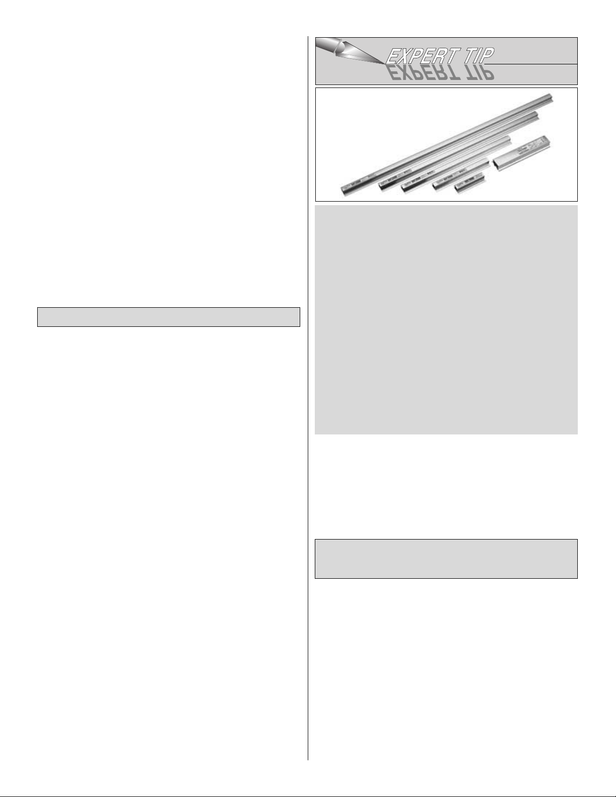
In our busy workshop we use the Great Planes Easy-
Touch
Bar Sanders equipped with Great Planes #80, #150 and
#220-grit Easy-Touch Adhesive-Backed Sandpaper. Great
Planes Easy-Touch Bar Sanders are made from light
weight, rigid, extruded aluminum and can be found at
most
hobby shops. They are available in three sizes...5-
1/2"
(GPMR6169) and 11" (GPMR6170) for most general purpose
sanding and 22" (GPMR6172) for long surfaces
such as wing
leading edges. The Easy-Touch Adhesive-
Backed Sandpaper
comes in 2" x 12' rolls of 80-grit
(GPMR6180), 150-grit
(GPMR6183), and 220-grit
(GPMR6185) and an assortment
pack of 5-1/2" long strips (GPMR6189) for the short Bar
Sander.The adhesive backed sandpaper is easy to apply and
remove from your Easy Touch Bar Sander when it’s time for
replacement.
This setup is all that is required for almost any sanding task.
Custom sanding blocks can be made from balsa or hardwood
blocks and sticks for sanding difficult-to-reach spots. We also
keep some #320-grit wet-or-dry sandpaper for finish sanding
just before covering.
Suggested Building Supplies
4
Page 5
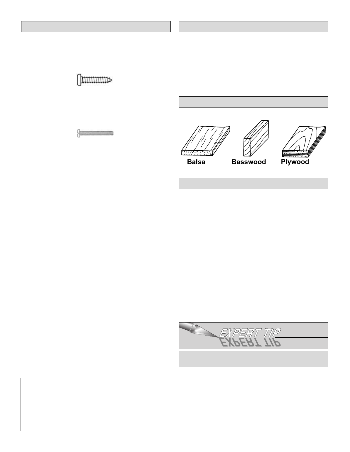
• There are two types of screws used in this kit:
Sheet metal screws are designated by a number and
a length.
For example #4 x 3/4"
Machine screws are designated by a number, threads per
inch, and a length.
For example 4-40 x 3/4"
• When you see the term “test fit” in the instructions, it means
you should first position the part on the assembly without
using any glue, then slightly modify or “custom fit” the part as
necessary for the best fit. Do not glue until told to do so.
• When you see the term “fit” in the instructions, it means you
should first position the part on the assembly without using
any glue, then modify or “custom fit” the part as necessary for
the best fit. Glue when you are satisfied with the fit.
• Whenever just “epoxy” is specified you may use
either
30-minute epoxy or6-minute epoxy. When 30-minute epoxy is
specified it is highly recommended that you use only
30-minute epoxy because you will need the working time
and/or the additional strength.
• Several times during construction we refer to the “top” or
“bottom” of the model or a part of the model. For example,
during wing construction we tell you to “glue the top main spar”
or “trim the bottom of the former.” It is understood that the “top”
or “bottom” of the model is as it would be when the airplane is
right-side-up and will be referred to as the “top” even if the
model is being worked on upside-down. I.E. the “top” main spar
is always the “top” main spar even when the wing is being built
upside-down.
• Where you see the term “glue,” it is at your option to select
the thickness of CA with which you are most comfortable. If the
step indicates a particular thickness of glue, be sure to use the
thickness recommended for strength, penetration, and/or
working time.
Fuse = Fuselage
Stab = Horizontal Stabilizer
Fin = Vertical Fin
LE = Leading Edge (front)
TE = Trailing Edge (rear)
LG = Landing Gear
Ply = Plywood
" = Inches
1. Unroll the plan sheet. Re-roll it inside out to make it lie flat.
Note: Do NOT cut the vertical fin plan from the fuselage
plan for assembly of the vertical tail.
2. Remove all parts from the box. As you do, figure out the
name of each part by comparing it with the plans and the parts
list included with this kit. Using a felt-tip or ballpoint pen, lightly
write the part name or size on each piece to avoid confusion
later. Use the die-cut patterns shown on back side of the center
pull-out section, to identify the die-cut parts and mark them
before removing them from the sheet. Save all scraps. If any
of the die-cut parts are difficult to punch out, do not force them!
Instead, cut around the parts with a hobby knife. After punching
out the die-cut parts, use your Bar Sander or sanding block to
lightly sand the edges to remove any die-cutting irregularities
or slivers.
3. As you identify and mark the parts, separate them into
groups, such as fuse (fuselage), wing, fin, stab (stabilizer) and
hardware.
Zipper-top food storage bags are handy to store the small
parts as you sort, identify, and separate them into sub-
assemblies.
Get Ready to Build
Types of Wood
Common AbbreviationsBuilding Notes
5
1/64" = .4mm
1/32" = .8mm
1/16" = 1.6mm
3/32" = 2.4mm
1/8" = 3.2mm
5/32" = 4mm
3/16" = 4.8mm
1/4" = 6.4mm
3/8" = 9.5mm
1/2" = 12.7mm
5/8" = 15.9mm
3/4" = 19mm
1" = 25.4mm
2" = 50.8mm
3" = 76.2mm
6" = 152.4mm
12" = 304.8mm
15" = 381mm
18" = 457.2mm
21" = 533.4mm
24" = 609.6mm
30" = 762mm
36" = 914.4mm
Metric Conversions
Page 6
Don’t forget to cover the plan with Great Planes Plan Protector
so the glue won’t stick to the plan.
Note: Be sure to save all of the leftover pieces from building the
stabilizer. These pieces will be utilized in constructing the fin.
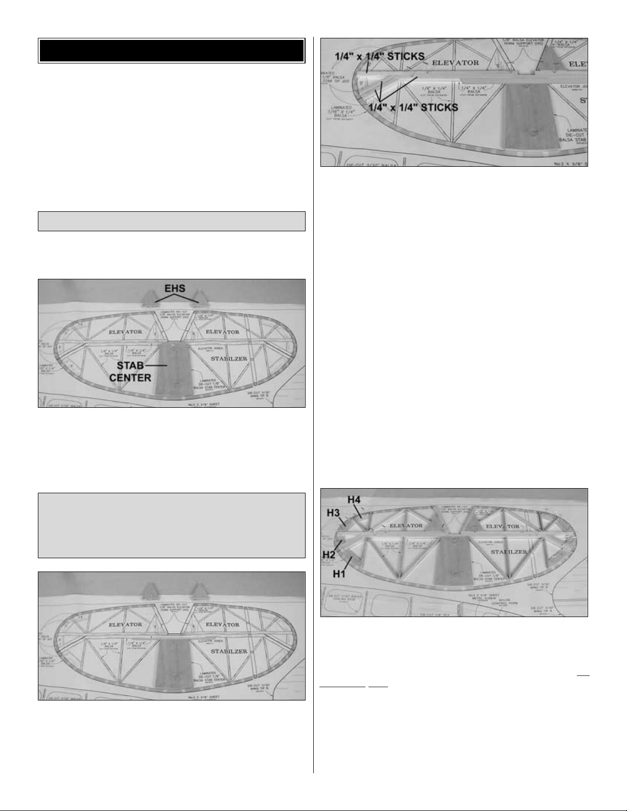
❏ 1. Laminate the two die-cut 1/8" balsa stab centers with
medium CA, creating the stab center. Laminate the four die-cut
1/8" balsa elevator horn supports EHS, creating two horn
supports.
❏ 2. Pin the stab center in position over the plan.
❏ 3. Select the 3/16" x 1/4" x 6" basswood stab spar. Sand a
bevel on both ends as shown on the plans. Glue the stab spar
to the stab center.
Note: Some stab photos do not show the stab spar in place.
Follow the text and plans.
❏ 4. From the 1/4" x 1/4" x 18" sticks, cut and glue the stab
trailing edge to the stab spar. Cut the stab trailing edge angles,
elevator leading edge, and elevator leading edge angles. Note:
Be sure to leave long enough segments of 1/4" x 1/4" stick for
the fin.
Hint: Single-edge razor blades work well for making clean
vertical cuts in sticks such as those used for the tail framework
on this model.
❏
5. Glue the angled portion of the stab trailing edge to the
straight
section of the stab trailing edge, and the angled portion of the
elevator leading edge to the straight section of the elevator
leading edge. Note: Do not glue the angled pieces to each
other.
❏ 6. Position the horn supports you made in step 1 and the
die-cut 1/8" balsa elevator jigs H1-H4 over the plans. From the
leftover 1/4" stick, cut, fit and glue the elevator roots to the
elevator leading edges and horn supports. Glue the horn
supports to the elevator leading edges. Note: The jigs are f
or
alignment only and DO NOT remain in the elevators.
❏ 7. Using 1/8" x 1/4" x 18" sticks, fit and glue the remaining
stab and elevator framework.
Note: Refrain from using excessive accelerator. Even hours after
it’s sprayed on, residual accelerator can prematurely and
unexpectedly cure the CA you use later on nearby glue joints.
Unless you must handle or remove the part from the building
board right away we recommend using no accelerator at all.
Build the Stab/Elevators
BUILD THE TAIL SURFACES
6
Page 7
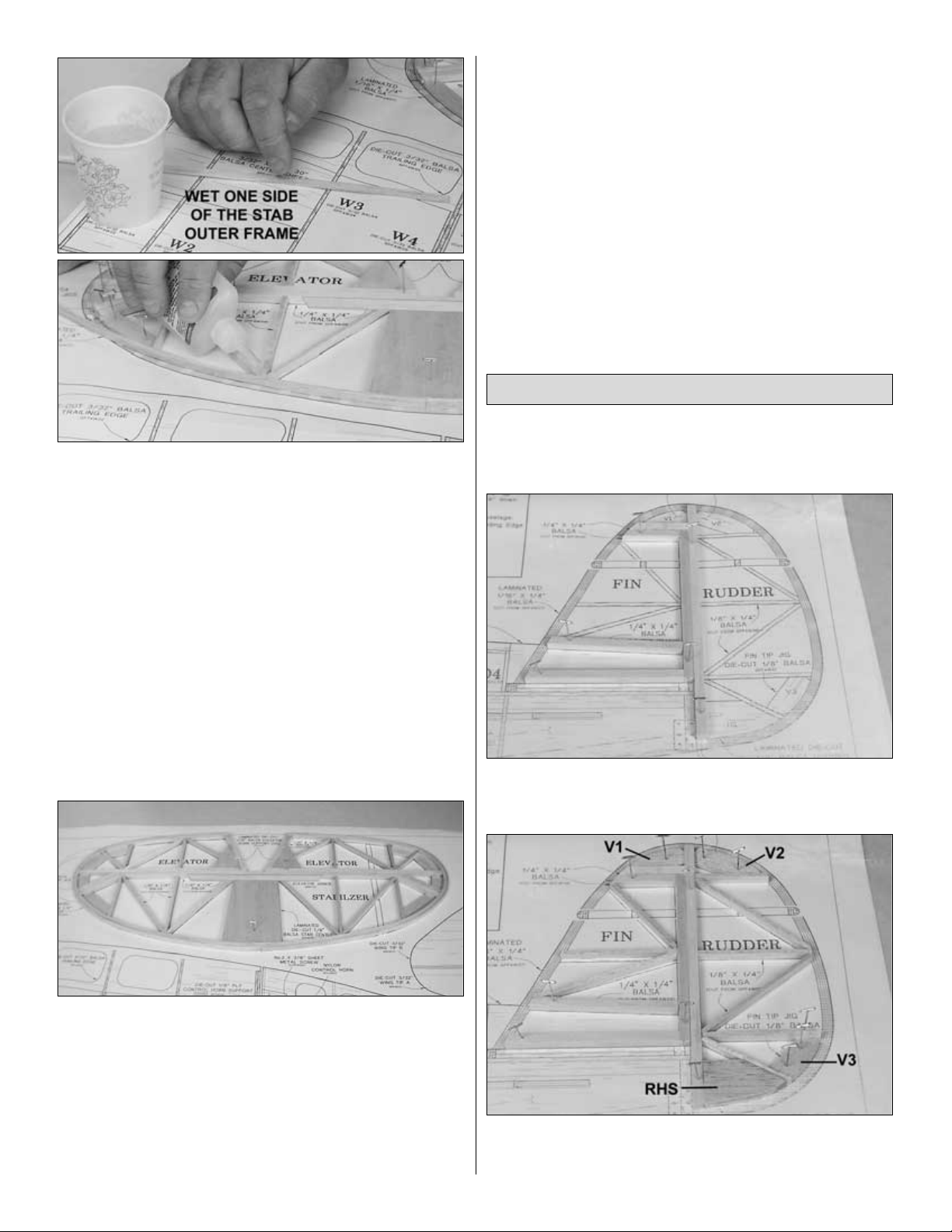
❏❏8. Select two 1/16" x 1/4" x 24" strips for the stab outer
frame. Wet one side of the first strip by dipping your finger in
water, then running it along the one side of the strip. Take care
not to wet both sides. Using medium CA, secure the dry side of
the strip to the middle of the stab center working toward the tip.
Note: Water accelerates CA much like commercial
accelerators,
so be careful not to get anything wet that should not be.
Hint: Another way to wet the strips is by holding them in the air
and spraying with a spray bottle. Do not spray the strips while
sitting on a flat surface, or both sides will get wet.
❏❏9. Slowly wrap the strip from the stab center all the way
around to the inboard elevator roots, securing it with thin CA as
you go. Take care to stay tight against the ribs, leading and
trailing edges, and jigs. Remember not to glue to the jigs.
❏ 10. Repeat steps 8 and 9 for the left side of the stab.
❏ 11. Wet one side of the next strip.Turn it over and lay a bead
of medium CA down the other side. Staggering the joint 1/2"
from all previous joints, but being sure to keep the joints
supported by the stab center, glue the next strip onto the
previous one. Trim the strip flush with the elevator inboard root.
Note: If you can work fairly quickly, the last applied strip will still
be wet on the outside. This will accelerate the CA, securing the
strips to one another immediately. If you crack the strip, don’t
worry. Just hold it in place until the medium CA cures and then,
seal it with thin CA if necessary.
❏
12. Apply the remaining 5 strips.Remember to stagger the
joints.
❏ 13. Unpin the stab from the plans and remove the jigs.
Inspect all glue joints and re-glue with CA as necessary. Use a
bar sander or a large sanding block and 220-grit sandpaper to
sand the entire top and bottom surface of the stab framework
until it is flat and even. Be careful while sanding so that you do
not over-thin any one particular area of the stab or gouge the
stab ribs by snagging the sandpaper on them.
❏ 14. Round all edges of the stab and elevators to the shape
shown on the cross-section on the plans. Hint: Labeling the
elevators “left” and “right,” and labeling the bottom of the stab,
will ensure proper assembly later.
❏ 15. Cut the stab outer frame between the elevator angled
leading edges and stab angled trailing edges, separating the
elevators from the stab. Sand the outer frame smooth.
Don’t forget to cover the fin area of the plan with Great Planes
Plan Protector so the glue won’t stick to the plan. DO NOT cut
the vertical fin plan from the fuselage plan.
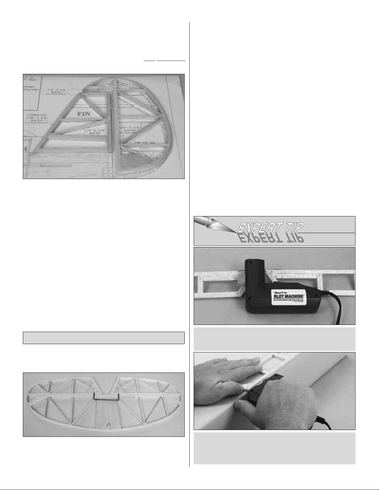
❏ 1. Using the leftover 1/4" x 1/4" balsa stick from the stab, cut,
fit, pin and glue all 1/4" sticks into the fin and rudder, being
careful not to glue any fin pieces to any rudder pieces.
❏
2.
Note: Refer to this photo for the following four steps.
Laminate the two die-cut 1/8" balsa rudder horn
supports RHS
making the rudder horn support.
Build the Fin/Rudder
7
Page 8
❏ 3. From a 1/8" x 1/4" x 18" balsa stick, cut, fit and glue the
fin and rudder inner framework in place. Position and glue the
rudder horn support to the framework.
❏
4. Position and pin the die-cut 1/8" balsa rudder jigs V1 –
V3
over the plan. Note: Remember that the jigs are
only
temporary
and should not be glued to any parts at any time.
❏ 5. Wet one side of one 1/16" x 1/4" x 24" balsa fin outer
frame strip. Use medium CA to glue the strip to the rudder,
then fin framework, wrapping from the bottom of the rudder
counterclockwise to the bottom of the fin as you did for the
elevator. Note: There are no joints on the vertical tail. All strips
wrap from the bottom of the rudder to bottom of the fin.
❏ 6. Wetting the outside and laying a bead of medium CA on
the inside face, apply the remaining three outer frame strips in
succession. Note: Remember that the outer strips will secure
more
easily to the inner layers if you work fairly quickly because the
water on the outside of the inner strips will accelerate the CA.
❏ 7. Unpin the fin/rudder, remove the jigs, and sand both sides
smooth. Round both the fin and the rudder as shown on the
cross-section on the plans.
❏ 8. Cut the outer frame between the fin and rudder and sand
the strips smooth.
Note: We do not recommend using any pin style hinges on
this model.
❏ 1. Lay the stab and elevators inverted on your work surface.
Align the elevators properly against the stab, taking care to
match the angled leading edges to the angled trailing edge of
the stab.
❏
2. Position the wire elevator joiner over the elevators,
centered
on and aligned with the trailing edge of the stab.Trace the joiner
onto the elevators.
❏ 3. Drill 1/8" holes through the elevators’ leading edges at the
position you marked to the depth you marked to properly fit
the joiner.
❏
4. Using a Great Planes Groove Tube™(GPMR8140), or a
sharpened
brass tube, cut a groove in the elevator leading edges from the
hole to the root so that the elevator joiner fits flush into the
elevators.
❏❏
5. Place the stab over its location on the plan. Lightly
mark
the hinge locations on the trailing edge with a ballpoint
pen.
Mark the hinge locations on the elevators in the same
manner.
To cut the hinge slot, place the blades onto the wood where
you want the slot. Lightly press the teeth into the wood. When
you are satisfied with the location, press the button on the
handle and the blades will cut easily into the balsa wood.
We have simplified the task of cutting hinge slots with the
introduction of the Great Planes Slot Machine
™
. This simple
electric tool cuts a perfect width slot for use with CA hinges.
Join, Bevel & Hinge the Tail Surfaces
8
Page 9
❏❏6. (
Complete step 6 only if you will not be using the
Great Planes Slot Machine to cut the hinge slots.)
Cut the
hinge slots in the elevator and stabilizer using a #11 blade.
Begin by carefully cutting a very shallow slit at the hinge
location to accurately establish the hinge slot. Make three or
four more cuts, going a little deeper each time. As you cut, slide
the knife from side to side until the slot has reached the proper
depth and width for the hinge.
❏ 7. Cut twenty-four 3/4" x 1" hinges from the supplied 2" x 9"
CA hinge material, then snip off the corners. Use 4 hinges to
temporarily join the elevators to the stab, adjusting any hinge
slots if necessary so they all align. Do not glue in the hinges
until you are instructed to do so.
❏
8. Return to steps 5 and 6 and complete the same
procedure,
using 3 hinges to hinge the rudder to the fin.
❏ 9. Shape the leading edge of the elevators and rudder to a
“V” as shown in the cross-section on the plans.
❏
10. Test fit the joiner wire into your elevator halves. Confirm that
the elevators lay flat on your work surface. Bend the joiner
slightly as needed to achieve perfect alignment. Epoxy the
elevator joiner into both elevator halves.
That’s about it for the tail surfaces. They’re a little more work
than stick or sheet surfaces, but they are much lighter,
exceptionally strong, and a nice piece of craftsmanship. Clean
off the building board and get ready for the wing!
Right now, while the building board is clear, is a great time to
assemble the wing sheeting.
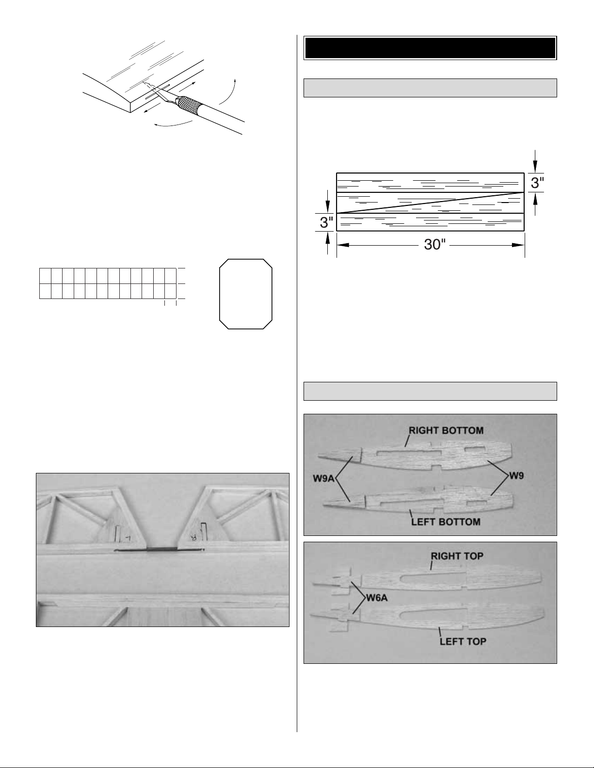
❏❏1. Edge glue three 3/32" x 3" x 30" balsa sheets together.
Make a diagonal cut from 3" down one short side to 3" up the
other short side of the sheet, starting and finishing the cuts at
the joints, creating two LE sheets.
❏
2. Repeat the step to build the LE sheets for the second
wing.
❏
1. Select both of the die-cut 1/8" balsa wing ribs W6 and
W9
and wing rib doublers W6A and W9A. Position the two W9
ribs mirrored to one another as shown in the photo. Glue the
two W9A doublers onto the outboard sides of W9 ribs. Position
the two W6 ribs mirrored, and glue the two W6A doublers onto
the inboard sides of the W6 ribs. Label the ribs right and left.
Prepare the Doubled Ribs
Assemble the Wing Sheeting
BUILD THE WING
1"
[25mm]
1"
[25mm]
3/4"
[19mm]
CUT HINGE SLOT
WITH HOBBY KNIFE
AND #11 BLADE
9
Page 10
At this time, you must decide if your model will have fixed or
retractable landing gear. The parts used are identical, but the
cut outs made will vary based upon which type of landing gear
will be installed. Carefully read and follow the instructions which
match your landing gear type.
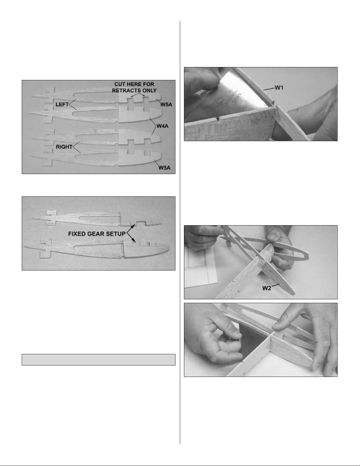
❏ 2. Select the two die-cut 1/8" ply wing rib doublers W4A
and W5A.
If you are using retracts,
cut out the 2 individual notches in the
ply doublers as shown in the photo.
If you are using fixed gear,
cut out the single notch in all four ply
doublers, two of which are shown in the photo.
❏ 3. Select the two die-cut 3/32" balsa wing ribs W4 and W5.
Position the W4 ribs mirrored to one another and glue the W4A
doublers onto the outboard sides of W4. Position the W5 ribs
mirrored to one another and glue the W5A doublers onto the
inboard sides of W5. Label the ribs left and right. Cut the
notches from the W4 and W5 ribs, using the notches in W4A
and W5A as guides.
We’ll begin by building the left wing upside-down over the left
wing bottom view plan. Remember that the wing is being built
upside-down as you work. Also keep in mind that we will refer
to the “bottom” or “top” as being the aircraft’s actual bottom or
top at all times.
Note that one wing panel on the plan demonstrates fixed gear
mounting and the other demonstrates retractable gear
mounting. If you are using retracts, you will still build your left
wing over the left wing view, but refer to the right wing view for
retract equipment mounting. If you are using fixed gear, you will
still build your right wing over the right wing view, but refer to the
left wing view for fixed gear mounting.
❏❏1. Cover the left wing panel plan with Great Planes Plan
Protector.
❏❏
2. Select the die-cut 3/32" balsa wing ribs W1 through
W9
and the die-cut 1/8" main web. Position and glue W1 onto the
web, making sure that the web aligns with the bottom of the
spar notch and is square to the rib, as shown in the photo.
Note: It is possible to put the ribs onto the web upside-down,
but the spar notches will not align if you do so. Be sure to
double-check every rib’s direction as you build. Also, it is
CRITICAL that the ribs be locked tight against the web and
square to the web.
❏❏3. Slide ribs W2 and W3 onto the web and lock in place
as shown in the photos. Confirm they are square, fully locked
against the web and right-side-up, and glue in place. Confirm
the W4, W5, W6 and W9 ribs you have are for your left wing
(doublers W4A and W6A are on the outboard side and W5A
and W9A are on the inboard side of the ribs). Position and glue
ribs W4 through W9 onto the web.
❏❏
4. Position one 1/8" x 1/4" x 30" basswood top spar over
the
plans, aligning the outboard end with the outboard edge of W9.
Assemble the Wing
10
Page 11
❏ 5. Position the ribs/web assembly you began in step 3
upside-down on the plans, locking the spar into the ribs. Glue
the spar to the web and ribs with thin CA. Pin along both sides
of the spar in at least 2 locations to make sure the spar stays
straight. Note:The top half of the rib is distinctly more curved
and should be toward the work surface, and the gear support
cut outs are away from the work surface.
❏❏
6. Test fit one 1/8" x 1/4" x 30" basswood bottom spar
into
the ribs, again aligning the outboard end with the outboard
edge of W9. Lay a bead of medium CA along the spar, then glue
it into the ribs and onto the web.
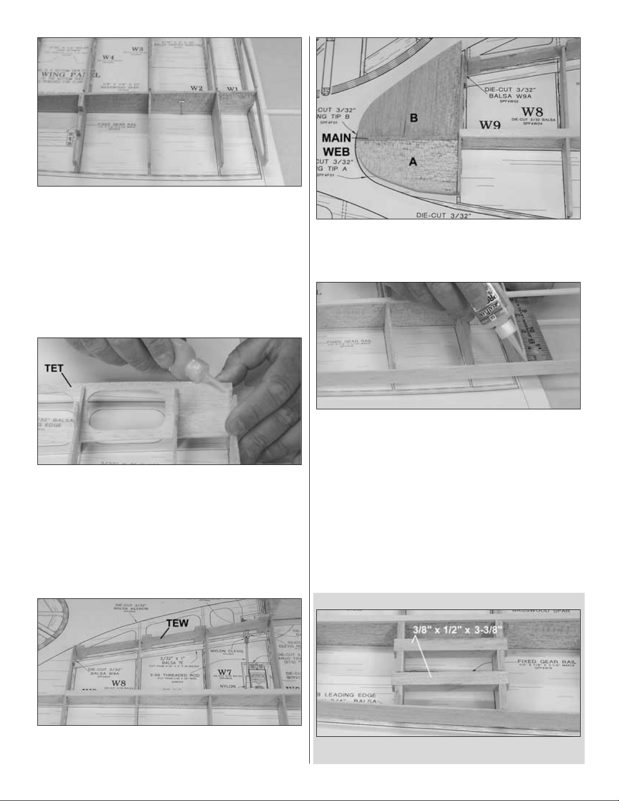
❏❏
7. Select one die-cut 1/8" balsa trailing edge top TET.
Test fit TET into the top slot of the ribs (remembering the wing
is upside-down). Slide TET out of the ribs, and sand a taper on
the trailing edge, using the cross-section on the plan as a
guideline. Note: TET and TEB are very similar, but TET has 3
holes; TEB has 4.
❏❏8. Slide TET back into the top notches in the ribs with the
beveled edge toward the bottom of the wing (remembering that
the wing is upside-down). Lock it tight against the ribs, then pull
it flush against the top of the wing ribs and glue to each rib.
❏❏9. Position and glue one die-cut 1/8" balsa trailing edge
web TEW to W6, W7, W8 and W9 over the plans, keeping it
straight and tight against the trailing edge of W7 and W8.
❏❏
10. Select one each die-cut 3/32" balsa wing tip A and
B.
Lock the tabs into W9 and align the outboard ends with the
main web. Glue the wing tips to the web and W9.
❏❏
11. Select one 1/16" x 3/4" x 30" balsa sub LE. Position
one
end centered on wing tip A with excess extending past the flat
area on the wing tip. Position the other end centered vertically
on W1, allowing the excess to overhang W1. Working slowly,
glue the sub LE to the wing tip, then to ribs W9 through W2.
Note: Do not glue to W1 at this time.
❏❏
12. Note that the main web may have twisted W1. Using
a
ruler or straight edge, be sure W1 is straight from trailing to
leading edge, then glue to the sub LE.
If you are using retracts, complete Steps 13R – 17R.
If you are using fixed gear, complete Steps 13F – 15F.
RETRACTS
❏❏13R. Select two 3/8" x 1/2" x 3-3/8" maple retract gear
rail. Position them in ribs W4 and W5 and glue in place.
11
Page 12
❏❏14R. Position the retract body over the gear rails and
against W4. Using a rotary tool or other cutting tool, cut a
groove through W4 for the gear’s actuator so that the retract
body sits flush on the retract rails tight against W4.
❏❏
15R. With the retract body in position, trace around the
retract
coil on the mounting rails. Using your rotary tool, cut away
where the coil makes contact so the retract strut can completely
retract at W4.
❏❏16R. Cut the retract strut to the length shown on the plan.
Note: The strut extends past the center of the wheel well to
support the axle.
❏❏
17R. Use a 3/32" drill to drill pilot holes through the
retract
body’s mounting holes into the retract rails. Using four #4 x 5/8"
sheet metal screws (not included), temporarily screw the retract
body to the retract rails. Trim W3 until the retract strut can lock
into its retracted position. Remove the retract from the wing and
use a small amount of thin CA in each of the 4 retract screw
holes to harden the threads.
❏ Proceed to Step 18.
FIXED GEAR
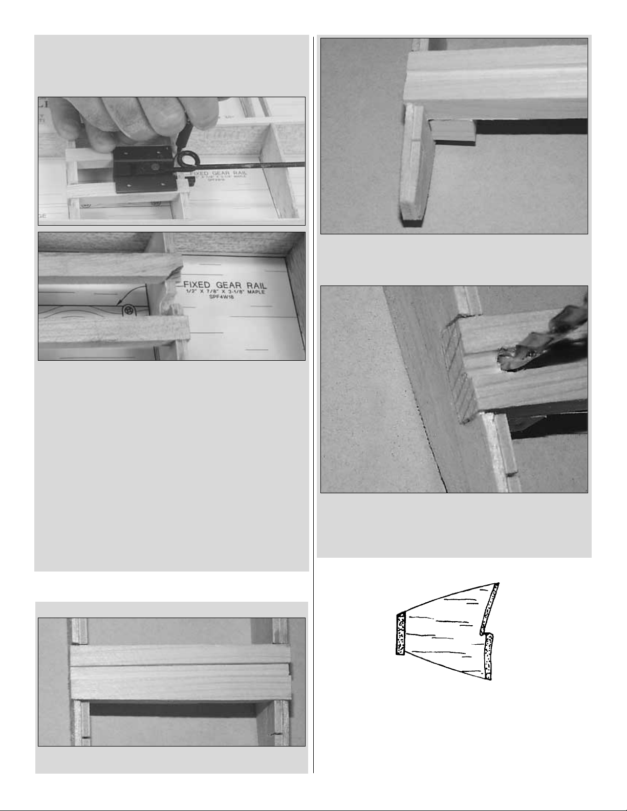
❏❏13F. Select one of the 1/2" x 7/8" x 3-3/8" maple fixed
gear rail. Position it in ribs W4 and W5 and glue in place.
❏❏
14F. Epoxy one of the 1/2" x 1/2" x 7/8" maple torque
block
to the top of the fixed gear rail and flush against W5. Note: The
leading edge is removed from this photo for clarity.
❏❏15F. Drill a 5/32" hole through the fixed gear rail and the
torque block with the outboard edge of the hole flush with the
W5A doubler.
❏ 16. Proceed to step 18.
❏❏18. Using a razor plane, shape the sub LE to match the
airfoil shape of the ribs as shown in the sketch.
❏❏19. Unpin the wing from the work surface. Select one LE
sheet you made earlier. Practice positioning the LE sheet with
the outboard edge flush with the outboard edge of W9 and the
12
Page 13
trailing edge on the center of the main spar. Coat the forward
half of the main spar with medium CA and press the LE sheet
down firmly in place, holding in position until the CA cures.
Carefully roll the sheeting back from the ribs and lay a bead of
medium CA along the ribs and the sub LE. Weight the sheeting
onto the ribs and sub LE and allow the CA to cure. Note: If
using retracts, do not glue the sheeting to the retract rails. If
using fixed gear, DO glue the sheeting to the fixed gear rails.
❏❏20. Lift the wing off the work surface. Trim and sand the
LE sheet flush with the sub LE and everything flush with W1.
❏❏
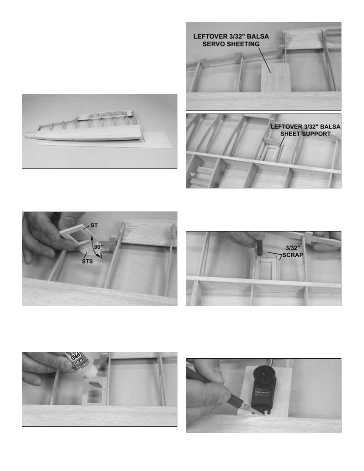
21. Glue the die-cut 3/32" balsa servo tray support
STS
perpendicular to the die-cut 1/8" ply servo tray ST as shown in
the photo.
❏❏22. Position ST flush against the top of the bottom spar
and W6, locking STS into the lightening hole in W6. Glue ST
and STS to the spar and W6.
❏❏
23. Using a piece of leftover 3/32" balsa, make servo
sheeting
over the servo tray. Glue the servo sheeting to the spar, W6 and
ST. Turn the wing right-side-up. Using another piece of leftover
balsa, cut and glue a sheeting support from ST to the servo
sheeting.
❏❏
24. Cut the opening for the servo in the sheeting, using
the
servo tray as a guide. Hint: While the wing is right-side-up, use
a hobby knife to cut just the corners of the servo opening. Turn
the wing upside-down again, and use a straightedge to cut
straight lines between the 4 corners you marked. Remove the
piece of sheeting.
❏❏
25. With the wing upside-down, fit the aileron servo in
place
and trim the sheeting around the servo, leaving room for the
13
Page 14

rubber grommets. Note: Provide approximately 1/16" of
clearance between the servo and the sheeting.
❏❏
26. Select one die-cut 1/8" balsa trailing edge bottom
TEB
(TEB has 4 holes). Test fit TEB into the bottom notches in the
ribs. Sand the trailing edge slightly, if needed, to mate flush with
TET and against the ribs. Using medium CA, coat all areas
where TEB makes contact with the ribs and TET. Hold TEB in
place until the CA is fully cured.
If you are using retracts, complete steps 27R – 29R.
If you are using fixed gear, complete steps 27F – 29F.
RETRACTS
❏❏
27R.Turn the wing right-side-up. Using the holes in the
retract
rails as a guide, drill 3/32" holes through the bottom LE sheeting.
Turn the wing upside-down. Temporarily screw the retract body to
the wing
as a template for where to cut for the bottom
sheeting.
Trim the sheeting around the retract body only. Note:
DO NOT cut
around the gear leg with the gear mounted upside-down.
❏❏28R. Remove the retract body from the wing and remove
the cut out sheeting. Remount the retracts upright in the wing
and cut out around the retract strut.
❏❏29R. Mount your axle and wheel (not supplied) to the
retract strut with the wheel centered between ribs W2 and W3.
Cut out the sheeting around the wheel, allowing 1/8" clearance
all the way around the wheel.
❏ Proceed to step 30.
FIXED GEAR
❏❏27F. Turn the wing right side up. Using the torque block’s
hole as a guide, drill a 5/32" hole through the bottom leading
edge sheet.
❏❏28F. Turn the wing over. Cut a slot out of the bottom
leading edge sheeting over the groove in the fixed gear rail. Fit
the 5/32" wire main landing gear into the rail.
❏❏29F. Secure the gear to the gear rail with four #2 x 1/2"
sheet metal screws and the two nylon landing gear straps as
shown on the plan. Remove the gear and straps and set aside.
❏❏30. From one 3/32" x 3" x 30" balsa sheet, cut two 5-1/2"
long pieces. Edge glue the two sheets, making one 3/32" x 5-
1/2"
x 6" center sheet. Cut, fit and glue the center sheet to W1, W2,
W3, the spar, and butted against TEB. Sand the center sheet
flush with W1.
❏
31. If this is your first time through, return to step 1 of “
Assemble
the Wing” on page 10, being sure to build a right wing.
14
Page 15

❏
1. Use epoxy to laminate the two die-cut 1/8" ply wing
joiners
WJ together.
❏ 2. Test fit the joiner to the wings as follows: slide the joiner
horizontally through the right wing panel’s ribs 1 and 2. Rotate
the wing joiner vertically so it locks flush against the web. Slide
the left wing panel over the joiner and rotate the left wing panel
into place. The roots of the spars should be flush against one
another. Sand the joiner slightly as needed to gain a perfect fit.
Note: Be sure the joiner is right-side-up so your wing has
dihedral, not anhedral.
❏ 3. Remove the joiner from the wings. Working over the Plan
Protector, coat the right face of the joiner and spar web with
epoxy and rotate the joiner into the right wing. Be sure the
epoxy secures the joiner flush to the web and spars. Allow the
epoxy to cure completely.
❏ 4. Coat the left face of the joiner and the root ribs with
6-minute epoxy. Rotate the left wing onto the joiner, ensuring a
tight fit to the joiner and aligning the leading and trailing edges
of the root ribs to one another. Allow the epoxy to cure
completely.
❏
5. Select the die-cut 1/8" ply retract servo tray parts RA,
RB,
and RC. Stand RC vertical against the web, spars, and bottom
sheeting, with the tab for RB pointing up. Glue RC in place.
❏ 6. Temporarily position RA as far forward as possible over
ribs W1. Position the tray, RB, onto the ribs and into the notch
in RC. Slide RA under the leading edge of RB to support it,
keeping RA vertical. Glue RA to ribs W1. Glue RB to RA and
RC. Note: Steps 5 and 6 must be completed even if you are
using fixed gear because RA also supports the wing dowels.
I
f you are using retracts, complete steps 7R – 17R.
If you are using fixed gear, skip to “Complete the
Wing Panels” on page 17.”
Note: In case you should ever have to repair your wing, the ideal
dihedral angle is 13-1/2 degrees. This is easily measured by
placing one wing panel flat on the workbench (right-side-up).
The tip of the second wing panel should be 5-1/2" off the work
surface. Please note that 5-1/2" is ideal with a perfect fit. Your
wing’s dihedral may vary by as much as 1/4" on each side (1/2"
total) without it negatively affecting the aircraft. A tight, proper fit
is more important than an exact tip measurement.
DESIGNER’S NOTE: We know what you’re thinking. “This is the
craziest joiner I have ever seen! WHAT were you thinking?” Bear
with us. You’ll soon see how this unusual shape helps to pull the
two wing halves together.
Join the Wing Panels
15
Page 16

RETRACTS
❏ 7R. Cut openings in the top of both ribs W1 to fit the retract
servo. If necessary, trim the bottom portion of the ribs as well to
fit the servo.
❏ 8R. Mount your retract servo and both retract bodies.
❏ 9R. Find a servo horn with two holes which are 1-1/16" to
1-1/8" from each other. Mount Screw-Lock Pushrod
Connectors
(GPMQ3870, not included) as shown. Hint: The standard 6arm Futaba servo horn works well – just trim off the four arms
that are not needed. Note: This horn should be installed for all
steps.
❏ 10R. Cut 5/8" of the threads off the end of two 12" threaded-
on-one-end pushrods. Attach clevises (GPMQ3772, not
included). Bend to the shape shown in the photo.
Note: The pushrod wire shown in the following four steps is not
the same as will be used in the model. It should be bent as
shown in the photo above. Follow the instructions and use
these photos for reference only.
❏
11R. Use a straightedge to mark a line from the center of
the
servo arm to the control link on the right retract on W2.
Repeat for the left retract.
❏ 12R. On the right wing half, mark on W2 where a line from
the aft screw-lock to the control link on the right retract
intersects W2.
❏ 13R. On the left wing half, mark on W2 where a line from the
forward screw-lock to the control link on the left retract
intersects W2.
16
Page 17

❏
14R. Cut a 1/4" deep slot between the marks on both ribs
W2.
❏ 15R. Plug your retract servo into your receiver. Set it so the
servo arm, in the “up” position, is rotated slightly, as shown in
the photo. Make sure it rotates clockwise to move the gear
down.
❏
16R. Hook up the pushrods with the gear in the “down”
position
and the arm as shown. Pull the pushrods until the gear locks
down, then tighten the set screws on the screw-lock
connectors.
❏ 17R. Remove the retracts and the servo from the wing.
Note: Label the retract bodies left and right and leave the
pushrods attached to the retracts to make it easier to reinstall
them later.
❏ 1. Fuelproof all wood between ribs 2 and 3 from the spars
forward. Hint: Fuelproof paint or thinned epoxy works well for
this task.
❏ 2. Turn the wing right-side-up. Use a sanding block to shape
the sub LE so it aligns with the tops of the ribs and the shape
of the airfoil.
❏❏
3. Weight the wing so that the left wing half stays flat on
the
building board. Select one LE sheet you made earlier. Test fit
the LE sheet with the inboard edge aligned with the center of
the wing and the trailing edge aligned with the center of the
spar. Coat the forward half of the main spar with medium CA
and press the LE sheet down firmly in place, holding in position
until the CA cures. Carefully roll the sheeting back from the ribs
and lay a bead of medium CA along the ribs and the sub LE.
Weight the sheeting onto the ribs and sub LE and allow the CA
to cure.
❏❏4. Trim the sheeting flush with the sub LE and W9.
Complete the Wing Panels
17
Page 18

❏ 5. Repeat steps 3 and 4 for the right wing half.
❏ 6. Cut the jig tabs off the top of the wing.
❏ 7. From one 3/32" x 3" x 30" balsa sheet, cut four 5-1/2" long
pieces. Edge glue two sets of two sheets together, making two
3/32" x 5-1/2" x 6" center sheets. Cut, fit and glue the center
sheet to W1, W2, W3, the spar, and butted against TEB.
❏ 8. Use a nickel to draw two circles on the center sheeting
roughly where shown on the plans. Use a hobby knife to cut out
the two circles.
❏ 9. Sand the top of the TE web to the shape of the ribs.
❏ 10. From a 3/32" x 3" x 30" balsa sheet cut four 3/32" x 1" x
11-1/4" TE sheets. Align one TE sheet with the TE web. Cut the
root end to the angle of the TE and round as shown in
the photo.
❏ 11. Use the TE sheet you just made as a template to cut the
other three. Glue the top two in place. Trim the outboard ends
flush with ribs W9.
❏ 12. Flip the wing over and trim the jig tabs off the bottom of
the wing. Trim the top TE sheets flush with the TE web.
❏ 13. Sand the bottom of the TE webs to the shape of the ribs.
Glue the remaining two TE sheets in place. Trim the sheets
flush with the TE web.
❏
14. Using 3/32" x 1/4" x 30" balsa sticks, fit and glue cap
strips
to all of the exposed ribs on both wing panels, top and bottom.
18
Page 19

❏ 15. Shape the TE of the cap strips on ribs W9 to match the
shape of the wing tips. Sand the inboard edges of the cap strips
in the aileron bays flush with ribs W9.
❏ 16. From a 1/4" x 3/8" x 18" balsa stick, cut six 2" hinge
blocks. Glue the hinge blocks in place on the front side of the
TE webs.
❏ 17. Glue the two 1/4" x 3/4" x 30" balsa wing LE to the sub
LE and the sheeting.
❏
18. Shape the LE as shown on the cross-section on the
plans.
❏ 19R.
If you are using retracts,
cut an opening in the top wing
sheeting for the retract servo. Note: Your wing should not be
covered at this time.
❏❏
1. Glue the die-cut 3/32" balsa aileron sub LE ALE to
the
die-cut 3/32" balsa aileron core AL using a square to keep
them perpendicular.
❏❏
2. Using leftover 3/32" balsa, fit and glue four aileron
ribs
in place.
❏❏3. Trim the ribs from the TE of the aileron core to the top
of the aileron sub LE.
❏❏4. Trim the aileron sub LE and the aileron root rib so that
the 1/8" die-cut ply control horn support CHS fits flush in the
bottom of the aileron. Glue the control horn support in place.
❏❏
5. Glue a second control horn support
in place over the
first but tight against the root rib.
❏❏
6. From a 1/4" x 3/4" x 24" balsa stick, cut an aileron LE
the
length of the ALE. Position the LE centered on the ALE and
glue in place. Trim the sides of the LE flush with the ALE.
Build the Ailerons
19
Page 20

❏❏7. Draw a centerline on the LE. Shape the LE of the
aileron to a “V.”
❏ 8. Repeat steps 1 through 7 to build the other aileron. Note:
be sure to build a left and right aileron.
❏
9. Using the same techniques as the stab, hinge the
ailerons.
❏
1. Cover the fuselage side view of the plans with Great
Planes
Plan Protector.
❏❏
2. Pin a die-cut 1/8" ply forward fuse side FFS over the
plan.
❏❏
3. Pin the die-cut 1/8" balsa aft fuse side AFS over the
plan.
❏❏
4. Using two 1/8" x 1/2" x 24" balsa sticks, cut, fit and
glue
the fuselage side sticks in place, building a right fuse side.
❏ 5. Remove the T-pins from the right fuse side. Write “RIGHT”
on the forward fuse former. Cover the right fuse side with Great
Planes Plan Protector.
❏ 6. Repeat steps 2 – 4, building the left fuse side over top of
the first.
❏ 7. Flip the left side over so it is a mirror image of the right,
as shown in the photo. Label the inside of the left side “left.”
❏ 8. Glue the die-cut 1/8" ply fuse doublers FS to the inside
of the right fuse side, using the die-cut 1/8" ply former F3 to
properly position FS. Repeat for the left side. Note: Do NOT
glue F3 in place at this time.
❏
9. Trim the right-thrust notch from the right fuse side as
shown
in the photo by cutting between the aft edge of the slots.
❏ 10. Lightly sand the outsides of each fuse side.
❏ 1. Position and glue the die-cut 1/8" ply forward fuse top
FFT and the die-cut 1/8" balsa aft fuse top AFT over the
plans.
Note: Remembering that the plans are a bottom view, be sure
to position the forward fuse top as demonstrated on the plans
to allow for the right thrust built into the air
craft.
Assemble the Fuselage Box
Assemble the Fuselage Sides
BUILD THE FUSELAGE
20
Page 21

❏ 2. Glue the die-cut 1/8" ply former F2A to the front of die-cut
1/8" ply former F2, aligning the dowel holes. Note: The
embossed
labels on each former are on the front side.
❏ 3. Position the die-cut 3/32" balsa formers F5, and F4, then
the die-cut 1/8" ply formers F3 and F2 into their notches in the
fuse top. Position the fuse sides inverted over the plan bottom
view, locking into the formers and the fuse top.
❏
4. Position the 1/8" die-cut ply aft fuse bottom AFB
between
the fuse sides and onto the formers. Checking that the fuse
sides are perpendicular to the work surface as you go, glue all
joints, working from the aft end of the fuse forward.
❏
5. Lift the fuselage off the plans. Carefully inspect all glue
joints,
and reinforce any weak joints with medium CA on the inside of
the fuselage.
❏ 6. Glue the two die-cut 1/8" ply fuse supports FS in place
in the bottom corners of the fuse.
❏ 7. Note: Refer to this photo for the following four steps.
Glue the two die-cut 1/8" ply bolt supports BS together.
❏
8. Place one die-cut 1/8" ply former F1 on the building
board,
punch marks and embossing facing up. Epoxy the second F-1
to the first with 30-minute epoxy, again with the punch marks
facing up. Make sure the edges all the way around are aligned.
Wipe away excess epoxy before it cures. From now on this
assembly will be referred to as the firewall. Note: If the formers
are warped, simply clamping them together may not “cancel
out” the warps. It is best to clamp the formers to a table or a flat
board until the epoxy cures.
❏
9. Using a straightedge, draw lines horizontally and
vertically,
connecting the punch marks. The intersection of these two lines
is the center of the engine mount.
Note: This location is offset for the right thrust built into the
model
so that the spinner will still align with the center of the cowl.
❏
10. Drill the four 11/64" (5/32" is OK) holes at the punch
marks
as shown in the photo for the included Great Planes Engine
Mount. Press the four supplied 6-32 blind nuts into the holes on
the back of the firewall. Gently tap the blind nuts with a hammer
to fully seat them into the firewall, then add a few drops of thin
CA around the blind nuts to secure them. Take care not to get
any CA into the threads of the blind nut.
❏ 11. Using 6-minute epoxy, position and glue BS into the wing
saddle, notched tight into both fuse doublers and against both
fuse sides.
❏ 1. If necessary, sand the entire wing saddle area lightly until
the fuse side doublers and fuse sides are flush. Note: Be
careful not to sand an angle into the wing saddle.
❏ 2. Test fit the wing on the fuse. Center the wing side-to-side,
leaving equal space between the fuse sides and the wing at the
leading edge. If necessary, sand or trim the wing’s trailing edge
slightly to properly fit the wing saddle.
Mount the Wing to the Fuselage
DESIGNER’S NOTE: The 2° right thrust built into the firewall
helps keep the aircraft tracking straight under acceleration and
deceleration, minimizing the need to apply right rudder in
coordination with throttle. This design requires no down thrust.
The thrust angles built into this aircraft have been extensively
tested and we recommend you do not modify them.
21
Page 22

❏ 3. Using the hole in F2 as a guide, drill one 1/4" hole all the
way through the leading edge and wing joiners, angling the drill
toward the bottom of the wing slightly to clear RB. Note: Use a
6" long, 1/4" drill bit or sharpened brass tube.
❏ 4. Round one end on each of the 1/4" x 4-1/2" dowels.
❏ 5. Glue one 1/4" x 4-1/2" dowel in the wing, leaving 3/8"
sticking out of the LE. Repeat for the second dowel.
❏
6. Mark a centerline on the die-cut 1/8" ply bolt plate BP
as
shown in the photo. Sand a taper on the leading edge and ends
of one side of BP. Flip BP over. Using a razor saw, cut 1/2 way
through the other side of the bolt plate so it can be bent to
match the wing.
❏
7. Stick a T-pin through the center of the aft end of the
fuselage
bottom. Tie a string to the T-pin. Pull the string to the TE of the
wing tip and put a piece of masking tape on the string at the
wing tip. Mark an arrow on the tape, then slide the tape on the
string so the arrow aligns with the wing tip. Swing the string over
to the other tip and see if it aligns with the same point. If
necessary, shift the wing and mark the location of the tip by
adjusting the position of the tape on the string. Do this until the
arrow on the string aligns with both tips.
❏ 8. Glue BP onto the wing, aligning the trailing edge with the
fuselage.
❏ 9. Holding the wing firmly in place on the fuse, and using the
holes in the wing bolt plates as a guide, drill one #7 (or 13/64")
hole through each wing filler block (inside the wing) and the
wing bolt block, (inside the fuse), keeping the drill perpendicular
to the wing bolt plates and centered in the holes.
❏
10. Remove the wing from the fuselage and enlarge both
holes
in the wing only to 17/64" (or 1/4").
❏ 11. Use a 1/4-20 tap to cut threads in the bolt block in the
fuselage. Hint: A cordless drill makes a great tap driver.
22
Page 23

❏
12. Harden the threads in the bolt block with thin CA, then
re-tap
the threads after the glue is completely dry.
❏ 13. Bolt the wing to the fuse with the 1/4-20 nylon wing bolts.
Turn the airplane right-side-up. Cut both wing bolts off, leaving
1/4" protruding above the wing bolt block.Turn the airplane
upside-
down and remove the wing from the fuse. Set the wing aside.
❏ 1. Glue F1 (the firewall) to the fuse sides with epoxy.
❏ 2. Using 1/4" x 1/4" balsa stick leftover from the stab, cut, fit
and glue a lower gluing stringer from the firewall into F2A and
flush against F2.
❏ 3. Cut one 4-3/4" long sheet from each of the two 1/8" x 3"
x 24" balsa sheets, making two forward fuse bottom sheets.
Lay a bead of medium CA along the bottom of the right fuse
side. Align the trailing edge of the sheet to the leading edge of
the wing saddle in the fuse side (which is approximately 1/4" aft
of F2). Glue the right forward fuse bottom sheeting to the right
fuse side. Note: This sheeting will maintain the shape of the
wing saddle.
❏ 4. Liberally wet the outside of the right forward fuse bottom
sheeting with an ammonia/water mix to help it bend. Gradually
wrap the sheeting around the fuse bottom. Holding it in place,
use a hobby knife to carefully trim the sheeting so that its edge
is centered on the lower gluing stringer. Apply a bead of
medium CA along the right half of the firewall bottom, F2, and
the gluing stringer. Press the sheeting firmly in place, ensuring
a tight joint with the firewall and F2.
❏ 5. Install the left side forward fuse bottom sheet as you did
the right.
❏ 6. Trim the trailing edge of the forward fuse bottom sheeting
to match the LE of the wing.
Finish the Bottom of the Fuselage
23
Page 24

❏ 1. Fit the die-cut 3/32" balsa turtle deck formers TD2, TD3,
and TD4 perpendicular to the fuse top. Fit the die-cut 3/32"
balsa turtle deck top TDT to the TD formers and glue all joints.
❏ 2. Fit and glue the die-cut 3/32" balsa turtle deck former TD1
and the die-cut 3/32" balsa radio gear floor RF to the fuse top
and TD2.
❏
3. Glue the die-cut 3/32" balsa front deck former FD1
perpendicular to the fuse top.
❏ 4. From leftover 1/4" x 1/4" balsa, cut a 12-1/8" long front
deck top gluing stringer. Position the stick flush with the
leading edge of the firewall. Position the die-cut 3/32" balsa
front deck former FD2 in the fuse top, using the front gluing
stringer to set its angle as shown in the photo.
❏ 5. From leftover 1/8" x 1/4" balsa, cut, fit and glue the two
cockpit side gluing stringers that run from the leading edge
of FD2 to the trailing edge of TD1.
❏❏
6. Select one 3/32" x 3" x 24" balsa sheet for the right
turtle
deck sheeting. Align the long edge of the sheeting along the
top of the fuse side sticks and the leading edge with the
center
of TD1. Glue the turtle deck sheeting to the fuse side sticks from
the center of TD1 through the aft edge of TD4.
Build the Top of the Fuselage
24
Page 25

❏❏
7. Wet, wrap and glue the turtle deck sheeting to TD2,
TD3,
TD4, the cockpit side stringers, and TDT, being careful not to
warp TDT.
❏❏8. Trim the sheeting flush with the aft end of TD4 and the
top of TDT.
❏ 9. Repeat steps 6 – 8 for the left side turtle deck sheeting.
❏ 10. Cut, fit and glue the 1/4" x 1-1/2" x 18" balsa turtle deck
top shaper from the leading edge of TD2 to the trailing edge of
TD4. Using a razor plane then sanding bars, contour the shaper
as shown on the cross-sections of formers F4 and F5.
❏❏
11. Select one 1/8" x 3" x 19-3/4" balsa sheet leftover
from
the forward fuse bottom for the right front deck sheeting.
Edge
glue the front deck sheet to the right forward fuse side, aligned
with the leading edge of the turtle deck sheeting.
❏❏
12.Wet the outside of the sheeting liberally with a
water/ammonia
mix. Test wrap the sheet over the front deck formers until you
can comfortably make contact with the center of the front deck
center gluing stringer. Glue the sheet to the formers, turtle deck
sheet, and cockpit side gluing stringers.
❏❏13. Trim the front deck sheeting along the center of the
center stringer. Look at the photo of the finished model on the
box cover, and note how the cockpit arcs from the center of the
front deck to the side stringers. This arc must be here to
properly support the canopy, so take your time. Using the photo
above and below as a guide, draw an arc on the right front deck
sheet which begins flush at the center of FD3 and ends flush
with the side stringers. When you are satisfied with the
positioning, trim the sheet along the arc you made.
❏ 14. Repeat steps 11 – 13 for the left front deck sheet.
❏ 15. Sand everything flush with the firewall.
25
Page 26

❏ 16. Select the two 5/8" x 1-3/8" x 5" balsa fillet blocks and
the two 1/4" x 1-3/8" x 5" balsa false stab and fin.
❏
17. Tack glue the false stab flat onto the aft fuse top and
TD4.
Tack glue the false fin vertically onto the false stab, centered on
TD4. Note: The false stab is 1-3/8" across the fuse, 1/4" tall and
5"
long; the false fin is 1/4" across the fuse, 5" long and 1-3/8" tall.
❏
18. Tack glue the fillet blocks to TD4 and the false stab and
fin.
❏
19. Using a razor plane and progressively finer grades of
sandpaper,
shape the fillet blocks until they blend into and follow
the contour of the fuselage.
❏ 20. Cut the fillet blocks and false stab/fin off the aircraft.
Gently remove the false stab and false fin from the fillet blocks.
Set the fillet blocks aside.
❏
1. Select the two 36" grey plastic outer pushrod tubes. Sand
the
outside of the tubes with coarse sandpaper so the glue will
stick.
❏ 2. Insert the rudder pushrod tube through the slot in the left
aft fuse side, through the center hole in F4, and through the
right hole in F3. Approximately 1/8" of the tube should protrude
past the rear edge of the slot in the fuselage side.
❏ 3. Insert the elevator pushrod tube through the hole in the
right aft fuse side, through the right upper hole in F4, and
through
the center hole in F3. Approximately 1/8" of the tube should
protrude past the rear edge of the slot in the fuselage side.
❏ 4. Glue the pushrod tubes to F3 and F4 with medium CA.
❏ 5. Use a mixture of 30-minute epoxy and microballoons to
secure the tubes to the slots at the aft end of the fuselage.
Completely fill the slots with the microballoons and epoxy. Allow
the epoxy to cure completely.
❏
6. After the epoxy has cured, use a bar sander and
sandpaper
to sand the outer pushrod tubes and epoxy filler flush with the
fuselage sides.
❏
7. Cut the excess pushrod tube inside the radio
compartment
1/4" aft of the servo opening.
❏
8. Using leftover 1/4" x 1/4" balsa stick, cut, fit and glue a
fuse
end cap between the fuse top, fuse bottom, and fuse sides at
the trailing edge of the fuse.
❏ 1. If you have not already done so, make sure the stab and
fin are final sanded to a smooth finish, as it will be a little more
difficult to do so after they are glued to the fuselage.
Mount the Stabilizer to the Fuselage
Install the Pushrod Tubes
26
Page 27

❏ 2. Accurately measure the trailing edge of the aft fuse top
and use a ballpoint pen to lightly mark the center. Use the same
procedure to mark the center of the stabilizer.
❏ 3. Mount the wing to the fuselage. Position the stab centered
on the aft fuse top, using the marks you just made for
alignment. Stand about six to ten feet behind the model and see
if the stab is parallel with the wing. If necessary, carefully use a
bar sander to make minor adjustments by sanding the aft fuse
top until the stab is in alignment with the wing.
❏
4. Place the stab on the fuse top with the center marks
aligned,
then use a large T-pin to attach only the trailing edge of the
stab to the fuse top.
❏ 5. Stick a T-pin through the front deck main stringer above
FD2, then use the “pin and string technique” to accurately align
the stab with the fuselage. Once the stab is accurately aligned,
pin the LE of the stab to the fuse top.
❏ 6. Carefully turn the fuselage over and use a ballpoint pen
to lightly mark where both fuselage sides contact the bottom of
the stab.
❏
7. Remove the stab from the fuse top but leave the T-pins in
the
stab. Apply a film of 30-minute epoxy to the fuse top and to the
stab between the lines you marked indicating the fuselage
sides.
❏ 8. Reposition the stab on the fuse top and reinsert the T-pins
into the same holes. Use the pin and string to confirm the stab
alignment, then use weights, more T-pins or clamps to hold the
stab in position. Wipe away excess epoxy before it cures.
Recheck alignment, then do not disturb the model until the
epoxy cures.
❏
1. Position the fin centered on the stab, using the mark on
the
trailing edge as a guide. Use a square laid flat on the stab to
align the fin lengthwise as shown in the photo. Mark the right
side of the fin, then remove the fin from the stab.
❏ 2. Lay a bead of medium CA along the bottom of the fin.
Position the fin on the stab, using the line you made as a guide.
Hold your square vertically on your stab to confirm the fin is
straight vertically and allow the CA to cure.
❏ 3. Glue the fillets to the stab, fin, and TD4.
❏ 4. Using the pieces from the false fin, fill the gap in front of
the fin and sand to shape.
❏ 1. Cut the “spreader bars” from the supplied Great Planes
engine mount, then use a hobby knife to remove any flashing
Mount the Engine
Mount the Fin
27
Page 28

leftover from the molding process so that the halves fit
together well.
❏
2. Temporarily attach the engine mount (inverted) to the
firewall
with four 6-32 x 3/4" machine screws and #6 flat washers. Do
not tighten the screws all the way, because you still need to
adjust the mount.
❏ 3. Place the engine on the mount and slide the halves in or
out until the engine fits properly. Position the mount so the
molded-in “tick marks” are equally spaced on the vertical
centerline you drew on the firewall. When the engine mount is
adjusted and positioned, tighten the mounting screws.
❏ 4. Position the engine on the mount so the front of the drive
washer (or the back of the spinner) is 4-3/4" away from the
firewall and clamp in place.
❏ 5. Use the Great Planes Dead Center
™
Engine Mount Hole
Locator (GPMP8130) to mark the locations of the bolt holes.
Remove the engine from the mount and drill four #36 (or 7/64")
holes. Tap the engine mount with a 6-32 tap for the 6/32 x 3/4"
machine screws.
❏ 6. Select the 11-3/4" grey outer pushrod guide tube for the
throttle. Use coarse sandpaper to roughen the outside of the
tube so the glue will stick. Using the location of your particular
engine’s throttle arm as a guide, drill a 3/16" hole through the
firewall for the throttle pushrod guide tube. Slide the throttle
pushrod tube through the firewall.
❏ 7. Position your throttle servo in the servo tray. Looking at the
left side of the inverted fuse, angle the pushrod tube so it will go
directly from the firewall to the servo arm, while keeping the
pushrod tube as close to the fuse side as possible. Drill a 3/16"
hole through F2 to match the angle and position of the pushrod
tube. Position and glue the pushrod tube flush with the front of
the firewall. Trim the excess pushrod tube 1/4" in front of the
servo tray. Note: It is important that the throttle pushrod be
close to the fuse side to allow clearance for the tank.
❏ 1. Temporarily mount the rudder to the fin with the hinges.
DO NOT GLUE. Mark the location of the tailgear wire on the
rudder and the nylon tailgear bearing on the fuselage, aligning
the nylon tailgear bearing touching the fuse bottom. Remove
the rudder.
Mount the Tailgear
28
Page 29

❏ 2. Drill a 1/8" (or 7/64") hole 5/8" deep in the leading edge
of the rudder at the mark you made for the tailgear wire. Cut a
groove in the rudder for the nylon tailgear bearing (use a Great
Planes Groove Tube tool or a 5/32" brass tube sharpened at
one end to cut the groove).Test fit the tailgear wire in the
rudder.
❏ 3. Position the control horn on the rudder as shown in the
sketch and on the plan. Use a ballpoint pen to mark the location
of the control horn mounting holes and drill 3/32" holes at the
marks. Temporarily mount the control horn to the rudder with
the backing plate and two 2-56 x 5/8" screws, trapping the
tailgear wire between the screws. Remove the control horn.
❏ 4. Cut a slot in the trailing edge of the fuse at the marks you
made for the nylon tailgear bearing. Without using any glue,
test
fit the rudder to the fin with the tailgear wire until there is no
gap.
❏ 1. Cut the cowl halves along the cutlines, then use a bar
sander with 80-grit sandpaper to true all the edges. To check
the straightness of the edges, set the cowl half on its seams on
the building board to be sure it is straight and smooth.
❏ 2. For now, just rough cut the openings in the front of each
cowl half. Using coarse sandpaper, roughen 1/2" along the
overlaps of each cowl half so the glue will stick.
❏
3. Tape the two pieces together, using several pieces of
masking
tape and taping across the seams. Note the overlap in the cowl
halves.
❏
4. Test fit the cowl to the fuselage and adjust the taped
seams
as needed for a proper fit. Carefully remove the cowl from the
fuselage. Note: You may need to remove your engine’s needle
valve, exhaust and possibly even the head to test fit the cowl.
❏ 5. Cut four 1" sections off the 1" x 18" fiberglass tape and
set aside for the cowl mounting screw locations. Secure the
inside of the cowl seams with the remaining fiberglass tape and
thin CA.
❏
6. Use a sharp hobby knife or a Dremel Multi-Tool with a
sanding
drum to accurately cut the openings at the front of the cowl.
❏
7. Slide the cowl onto the fuselage. Slide the spinner
backplate
over the crankshaft, moving the cowl as necessary to leave a
1/8" gap between spinner and cowl, and secure the backplate
in place. Position the cowl so that it aligns properly with the
spinner.
❏ 8. Hold the cowl in position tight against the front deck
sheeting and aligned with the spinner. Drill the first cowl
mounting screw hole with a 1/16" drill bit. Screw in place with a
#2 x 3/8" screw.
❏
9. Confirming the proper positioning of the cowl before
drilling
each hole, drill the remaining holes and install the remaining 3
screws one at a time.
❏
10. Remove the screws and the cowl from the model.
Enlarge
the pilot holes you just made in the fuse with a 1/8" drill bit.
From the 6" piece of white pushrod inner, cut four 1/4" lengths,
making four cowl screw retainers. Push the retainers into
each hole until flush with the fuselage side. Glue in place with
thin CA from the inside of the fuselage. Note: These plastic
retainers help keep cowl screws from vibrating loose.
❏
11. Use a piece of thin cardboard or plastic to make a
template
for the cutout in the cowl for the valve cover and mixture screw
of the engine, and for access for the glow plug heater.Tape the
template to the fuselage side, accurately indicating the
positions.
❏ 12. Remount the cowl in position with the mounting screws,
being careful not to move or damage the paper template. Use
a felt-tip pen to transfer the holes in the template onto the cowl.
Assemble the Cowl
29
Page 30

❏ 13. Remove the cowl and template, then remount the valve
cover and/or needle valve, if necessary. Cut out the holes in the
cowl, then test fit it to the fuselage (you may have to temporarily
remove the needle valve so it does not interfere with the cowl.)
Adjust the position and size of the holes as needed. Hint: Cut
the holes in the cowl undersize at first so you can make
adjustments to their position without having to enlarge them.
❏
14. Roughen the inside of the cowl at the mounting holes
with
sandpaper. Use medium CA to glue one of the 1" x 1" fiberglass
squares to the inside of the cowl at each cowl mounting hole.
After the glue dries, enlarge the holes with a 3/32" drill bit.
❏ 15. Fill the seams and other imperfections in the cowl with
putty filler such as Squadron
®
White Putty™or automotive filler
such as Bondo
®
. We use Bondo most of the time as it cures
quickly and is easy to sand, but usually it must be purchased in
large quantities. Squadron putty works well but it takes
overnight to dry and usually requires at least two applications
because it shrinks as it dries.
❏
16. When dry, wet sand the entire cowl with 400-grit
sandpaper
to prepare it for priming.
Do not confuse this procedure with “checking the C.G.,”
which will be discussed later in the manual.
A model which is not laterally balanced properly may exhibit a
variety of unpleasant tendencies, ranging from uncharacteristic
tip stalls to problems with spin entries. This aircraft, when
balanced properly, has NO such bad tendencies. Be sure to
check the lateral balance carefully to help ensure that the
model exhibits the same exceptional handling qualities as our
prototypes.
❏ 1. With the wing level and attached to the model (and the
engine and muffler installed), lift the model by the propeller
shaft and the aft bottom of the fuse. This may require an
assistant. Do this several times.
❏ 2. If one wing consistently drops, that is a heavy tip. Balance
the model laterally by adding weight to the light wing tip.
❏ 1. Remove all servos, pushrods, hinges and control horns.
Remove the engine, mount and any other hardware you may
have installed.
❏ 2. Most of the model should be rough-sanded by now, with
all the tabs and rough edges sanded even. Fill all dents, seams,
low spots, and notches with HobbyLite
™
Balsa Colored Filler.
❏ 3. After the filler has dried, use progressively finer grades of
sandpaper to even all the edges and seams and smooth all
surfaces. Remove all balsa dust from the model with
compressed air or a vacuum with a brush. Then use a tack cloth
to give the model a final wipe down.
❏ 4. Cut the canopy along the outside cutlines. DO NOT cut
along the second set of lines, provided as “paint to here” locator
lines to help you paint the canopy. Test fit and trim as
necessary.
Cover the model with Top Flite MonoKote Film using the
recommended covering sequence that follows. Before you
cover the fuselage, first apply strips of MonoKote film 1/4"
larger than the fillets on top and 1/4" overall for the bottom into
the corners of the stab and fuse and the fin and the fuse. Then
proceed to cover the fin and stab with pre-cut pieces that meet
in the corners and overlap the 1/4" strips. Never cut the
covering on the stab and fin after it has been applied
except around the leading and trailing edges and at the
tips. Modelers who cut covering on top of the wood structure
may cut through the covering and into the stab or fin. This will
weaken the structure to a point where it may fail during flight.
Only the prototype’s canopy and cowl are painted (see below).
All other covering is done with MonoKote Flat Finish Grey and
Green and Opaque colors.
Fuselage:
❏ 1. 1/4" strips at fin and stab as described above (camo on
top, grey on bottom)
❏ 2. Fin top then stab ends (grey)
❏ 3. Stab/elevators bottom, then top (grey bottom, then
camo on top)
❏ 4. Fin/rudder right side, then left side (camo)
❏ 5. Turtle deck (camo)
❏ 6. Front deck (camo)
❏ 7. Aft fuse bottom (camo base)
Suggested Covering Sequence
The wing, stab and fin coverings are pre-made sections of
covering. For one side of the stab’s top, begin with a piece of
oversized covering of the base grey. Peel off the backing,
laying the covering onto a large piece of clean glass.
Freehand cut your camouflage shapes from the grey. Peel the
backing off an oversized piece of green. Using the cut grey as
a guide, cut the camouflage shape into the green, allowing for
a 1/4" overlap of the green onto the grey. Lay the green with
a 1/4" overlap over the grey. Using a very hot MonoKote iron,
secure the green to the grey.
Gently peel the oversized camouflage covering you just
assembled, lay it onto the stab, and iron in place as you
would a single piece of covering. Doesn’t it look great?! No
bubbles and no large excesses of covering, either!
Covering Technique
COVER THE MODEL WITH
MONOKOTE
®
FILM
PREPARE THE MODEL
FOR COVERING
BALANCE THE MODEL LATERALLY
30
Page 31

❏ 8. Forward fuse bottom (camo)
❏
9. Fuse sides overlapping 1/8" onto deck coverings
(camo)
❏ 10. Finishing markings (black/white/decals)
Wing:
❏ 1. Trailing edges of wing in aileron bays and cap of aileron
bay (grey, other colors will wrap)
❏ 2. Bottom of right, then left panel (grey)
❏ 3. Top of right, then left panel (camo)
❏ 4. Aileron tips, then bottom, then top of aileron (grey
then camo)
❏ 5. Finishing markings (black,white, decals)
After the model is covered, you must fuelproof the firewall. You
may do so with fuelproof model paint, 30-minute epoxy thinned
with alcohol, or finishing resin. If you prefer, you can cover the
firewall with MonoKote, cutting out for the fuel lines and
pushrod tube, and trimming and sealing the covering around
the holes.Then seal the covering seams with thin CA, which will
fuelproof the firewall very nicely and look sharp to boot!
Top Flite LustreKote
®
fuelproof paint is recommended for
painting the ABS plastic cowl. At least one coat of LustreKote
primer is highly recommended to fill all the small scratches left
from sanding as well as small pin holes in the filler. Wet sand
between coats with 400-grit sandpaper and apply a second
coat of primer if necessary. If the parts are primed properly, a
few light coats of color will quickly provide a beautiful match to
the MonoKote.
Before painting the canopy, use 400-grit sandpaper to scuff the
frame portion of the canopy so the paint will stick. We
recommend painting the canopy frame (and cockpit) with
Pactra Formula-U or Chevron Perfect Paint. Use masking tape
to cover the portion of the canopy that is not to be painted. If
you are not sure that the paint is compatible with the clear
canopy, test the paint on a scrap piece of canopy material,
allowing at least 24 hours to see if the butyrate will deform.
For painting the pilot we have discovered that acrylic water
base paints such as the Horizon Paints available through your
favorite hobby shop or those found at craft stores work great.
The acrylic paints look realistic on the pilot because they are
not glossy and, best of all, they clean up with water.
❏ 1. Reinstall the engine and mount. Using your engine
installation as a guide, drill two 1/4" holes through the firewall
for the fuel lines. Fuelproof the openings.
❏ 2. Using the instructions provided, assemble a Great Planes
10 oz. tank (not included).The vent line will attach to the nipple
on your muffler for pressure. The main feed line will attach to
the fuel filler valve. Note: This aircraft is designed around this
specific tank. If you choose to use a different tank, you may
need to modify the installation accordingly.
❏ 3. Install your fuel filling system. We recommend the Great
Planes Easy Fueler (not included). Using leftover 1/8" plywood,
create and install a mount for the filler which positions the filler
flush with the outside of the cowl. Secure the filler to the mount.
❏ 4. Attach two 12" lengths of nitro-safe fuel line (not included)
to the 2 nipples on the tank. Guiding the fuel lines out the
opening in the firewall, slide the tank into position through F2.
Note that the tank locks into the fuse top. Using two #2 x 1/2"
sheet metal screws, attach the 1/8" ply tank retainer behind the
tank, securing the tank in place.
❏ 1. Start with the elevators and stab. Cut the covering from
the hinge slots – don’t just slit the covering but remove a small
strip the size of the hinge slot.
AWAY FROM THE SLOT
CUT THE COVERING
Attach the Control Surfaces
Assemble & Install the Tank & Fuel Filler
FINAL HOOKUPS & CHECKS
PAINT THE MODEL
31
Page 32

❏ 2. If you did not use a Slot Machine to make your hinge slots,
drill a 3/32" hole 1/2" deep in the center of each hinge slot. A
high speed Dremel Multi-Tool works best for this. If you use a
regular drill, clean out the hinge slots with a #11 blade.
❏ 3. Without using any glue, fit the hinges in the elevators or
stab. Do not glue the hinges yet. As you join the elevators to
the stab, confirm that the hinges are equally inserted in the
elevators and the stab. Insert a small pin in the center of the
hinges to keep them centered.
❏ 4. Remove the pin and add 6 drops of thin CA to the center
of all the hinges on both the top and the bottom.
Do not use accelerator on any of the hinges. Do not glue
the hinges with anything but thin CA and do not attempt to
glue one half of the hinge at a time with medium or thick
CA. They will not be properly secured and the controls
could separate while the model is in flight.
❏ 5. Prepare the hinge slots for the rudder as you did the
elevators. Join the rudder to the fin with the hinges and use
30-minute epoxy to simultaneously glue the tailgear wire in the
rudder and the tailgear bearing in the fuse. Do not glue the
nylon bearing to the rudder. Glue the hinges in position with
thin CA. Note: Petroleum jelly on the areas where the tailgear
bearing contacts the wire will ensure that it does not become
glued to the tailgear wire or rudder.
❏ 6. Prepare the hinge slots in the ailerons the same way you
did for the tail surfaces. Glue the hinges with thin CA.
❏ 1. Install a nylon clevis on the 17-1/2" throttle pushrod wire.
Slide the throttle pushrod through the pushrod tube with the
clevis on the servo end. Without attaching the clevis to the
servo, bend the pushrod as needed to make the pushrod move
smoothly and the clevis properly reach the servo arm.
❏ 2. Bend and/or cut the engine end of the throttle pushrod as
needed to fit the engine installation. Make adjustments to the
bends in the wire so the pushrod aligns with the carburetor arm
on the engine. Slide a 2" piece of white pushrod inner over the
pushrod and glue it to the pushrod at the distance where the
pushrod exists the firewall. Note: This plastic bearing will
minimize fuel running back down the pushrod tube.
❏ 3. Temporarily connect the pushrod to the carb arm with
whatever connection type you have selected for the throttle.
(We recommend the simplicity of using a Z-bend.) Temporarily
mount the muffler and make sure the throttle pushrod will not
interfere with the muffler. Make adjustments to the bends in the
wire if necessary.
❏
4. Trim the covering from the pushrod openings in both
sides
of the fuse.
❏
5. Slide the die-cut 1/8" ply pushrod support over the servo
ends
of the elevator and rudder pushrods. Do not glue it at this time.
❏ 6. Screw a clevis onto one 35" pushrod wire (threaded on
both ends) for the rudder pushrod. Slide the pushrod wire
through the rudder pushrod guide tube, which is the guide tube
Install the Servos & Make the Pushrods
THE CA WICKS
ALONG THE "TUNNELS"
TO THE ENTIRE
HINGE SURFACE
32
ASSEMBLE, THEN APPLY 6 DROPS
OF THIN CA TO CENTER
OF HINGE, ON BOTH SIDES
Page 33

exiting the left side of the fuselage. Re-mount the rudder control
horn. Attach the clevis to the control horn.
❏ 7. Position the rudder servo in the right side of the servo tray
as shown on the plans, using a servo arm included with your
radio to position the servo such that the end of the servo arm
lines up with the pushrod. Mount the servo.
❏ 8. Center the rudder (clamping the counterbalance to the fin
and using balsa pads to keep from damaging the rudder works
well) and be sure the servo arm is perpendicular to the servo
case. Cut the pushrod 1/2" forward of the servo arm and set
aside the excess pushrod for an aileron. Mark the pushrod
where it crosses the servo arm. Bend the pushrod and connect
it through the outer hole of the servo arm with a Faslink. Trim
the excess wire that sticks out past the Faslink.
❏ 9. Screw a clevis onto one end of the 35" pushrod wire
(threaded on both ends) for the elevator pushrod. Slide the
pushrod through the elevator pushrod guide tube, which is the
guide tube on the right side of the fuselage. Remove the
backing plate from the nylon control horn and connect the horn
to the clevis in the outer hole. Position and temporarily mount
the elevator control horn as you did the rudder control horn.
❏ 10. Position the elevator servo centered in the servo tray as
shown on the plans, using a medium servo arm included in your
radio to position the servo such that the end of the servo arm
lines up with the pushrod. Mount the servo.
❏
11. Center the elevators (clamping them to the stab and
using
balsa pads to keep from damaging them) and be sure the servo
arm is perpendicular to the servo case. Trim and set aside the
excess pushrod as you did for the rudder. Mark the pushrod
where it crosses the servo arm. Bend the pushrod and connect
it to the center hole of the servo arm with a Faslink. Trim the
excess wire that sticks out past the Faslink.
❏ 12. Select the two servos you are using for the ailerons and
attach a 12" servo extension to each. Guide the extensions
through the wings and out the holes in the top of the wing. Hint:
A wheel collar tied to a string, with the string slip-knotted over
the control horn, will help guide it through the wing.
❏ 13. Mount the aileron servos in the wing with the screws
provided with your radio. Mount the aileron control horns to the
ailerons with #2 x 1/2" screws without the backplate.
❏ 14. Screw the clevises onto the pushrod wires leftover from
the elevator and rudder.
❏ 15. Connect the clevis to the control horn. Center the aileron
and position the servo arm perpendicular to the servo case.
Mark the pushrod where it crosses the servo arm. Bend the
pushrod and connect it to the servo arm with a Faslink. Trim the
excess wire that sticks out past the Faslink.
❏
1. Install a 3/4" tail wheel (not included) with a 3/32" wheel
collar.
❏ 2. Reinstall the landing gear, fixed or retractable.
❏ 1. Temporarily position the receiver and battery on the servo
tray. Connect all servos to your receiver.
❏ 2. Turn on the transmitter and center all trims. Turn on the
receiver switch. Reposition the servo arms and clevises as
needed to make the servo arm perpendicular to the servo case
and the surface centered. Check that both servos move the
correct direction, remembering that the wing is upside-down.
(Reverse the servo direction in the radio if required.) Set the
wing aside for now.
❏
3. Confirm all servo arms are all positioned so the servo
arms
are perpendicular to the cases, including the throttle servo with
the throttle stick and trim at center. Check servo direction and
center the rudder and elevator as you did the ailerons.
❏
4. Check that the throttle servo moves in the correct
direction,
and reverse if necessary. Adjust the clevis on the throttle
pushrod as needed so that when wide open, the throttle barrel
Final Servo & Receiver Installation
Install the Landing Gear
33
Page 34

just opens completely, but does not bind (a buzzing sound of
the servo trying to push the arm farther than wide open).
Additionally, at low throttle with the throttle trim at center the
barrel should be open just slightly – enough to allow the engine
to run, while with the trim pulled all the way back the barrel is
completely closed, again without binding.
❏ 5. After setting the control throws (see following box), turn off
the receiver and transmitter.
Note: The balance and control throws for the Spitfire have
been extensively tested. We are confident that they
represent the settings at which the Spitfire flies best.
Please set up your model to the specifications listed
above. If, after you become comfortable with your Spitfire,
you would like to adjust the throws to suit your tastes,
that’s fine. Too much throw can force the plane into a stall,
so remember, “more is not better.”
❏ 1. Rough-cut the canopy from the flashing, leaving 1/4" of
excess below the cut lines.Test fit the canopy to your model and
trim as required.
❏ 2. Install the instrument panel decal. If desired, install a pilot
(optional, not included).
❏ 3. Place the canopy on the fuselage in the location shown
on the plan, then temporarily hold it in position with tape or
rubber bands.
❏ 4. Use a felt-tip pen to accurately trace the canopy outline
onto the MonoKote film covering. Remove the canopy.
❏ 5. Use a sharp #11 blade to
carefully
cut the covering about
1/32" inside of the line you marked without cutting into the
balsa. Cut the covering 1/16" inside of the seam you just made,
again without cutting into the balsa. Carefully remove the 1/16"
wide strip of covering. Wipe away the ink line with a paper towel
lightly dampened with alcohol.
❏ 6. Before you permanently glue the canopy to the fuselage,
securely glue the pilot in place.
❏ 7. Reposition the canopy on the fuselage and confirm that it
covers the exposed wood. Glue the canopy to the fuselage
using rubber bands or masking tape to hold it in position until
the glue dries. We recommend a glue specifically formulated for
gluing on canopies such as Pacer “Formula 560” canopy glue.
Formula 560 is like regular white glue (aliphatic resin) in that it
dries clear and cleans up with water but sticks extremely well to
butyrate and dries overnight (to allow for accurate positioning).
❏ 8. Install the cowl, then mount the spinner backplate, prop,
prop washer, and prop nut. Install the spinner. Reinstall the
needle valve and exhaust deflector, if necessary.
❏
9. Some modelers prefer to cushion the wing with wing
seating
foam tape on the wing saddle of the fuselage. Apply 1/16"
seating tape on the wing saddle of the fuselage if you choose.
Note: This section is VERY important and must NOT be
omitted! A model that is not properly balanced will be
unstable and possibly unflyable.
❏
1. Wrap the battery pack in at least 1/4" of foam rubber,
secure
to a piece of leftover ply (we prefer Velcro
®
for this task for easy
removal), then temporarily position it on the aft fuse top.
❏ 2. Mount the receiver switch in a convenient location that will
not interfere with the servos and pushrods inside the fuselage
and opposite of the engine exhaust.
Balance Your Model
Mount the Canopy & Cowl
We recommend the following control surface throws:
Note: The throws are measured at the widest part of the
elevators, rudder, and ailerons. Adjust the position of the
pushrods at the control/servo horns to control the amount of
throw. You may also use the ATV’s (if your transmitter has them)
but the mechanical linkages should still be set so the ATV’s are
near 100% for maximum servo power and the best servo
resolution (smoothest, most proportional movement).
High Rate Low Rate
ELEVATOR: 9/16" up 5/16" up
9/16" down 5/16" down
RUDDER: 1" left 5/8" left
1" right 5/8" right
AILERONS: 7/16" up 1/4" up
7/16" down 1/4" down
Note: If the radio does not have dual rates, then set the control
surfaces to move between the high rate and low rate throws.
4-CHANNEL
TRANSMITTER
4-CHANNEL
TRANSMITTER
4-CHANNEL
TRANSMITTER
4-CHANNEL RADIO SET-UP
(STANDARD MODE 2)
TRANSMITTER
4-CHANNEL
ELEVATOR MOVES UP
RIGHT AILERON MOVES UP
LEFT AILERON MOVES DOWN
RUDDER MOVES RIGHT
CARBURETOR WIDE OPEN
Set the Control Throws
34
Page 35

❏ 3. Accurately mark the balance point on the top of the wing
on both sides of the fuselage. Use thin strips of tape or a
felt-tip pen to make the marks. The balance point (C.G.) is
located 3-3/4" back from the leading edge where the wing
meets the fuse as shown in the sketch and on the wing plan.
This is the point at which the model should balance for your first
flights. After initial trim flights and when you become more
acquainted with your Spitfire, you may wish to experiment by
shifting the balance up to 1/2" forward or 3/8" back to change
the flying characteristics. Moving the balance forward may
improve the smoothness and stability but the model may then
require more speed for takeoff and make it more difficult to slow
for landing. Moving the balance aft makes the model more
agile with a lighter, snappier “feel” and often improves knife-
edge capabilities. In any case, please start at the location we
recommend and do not at any time balance your model
outside the recommended range.
❏ 4. With the wing attached to the fuselage, all parts of the
model installed (ready to fly) and an empty fuel tank, hold the
model upside-down with the stabilizer level.
❏ 5. Position the model on a Great Planes C.G. Machine
™
, or
manually lift the model at the balance point. If the tail drops
when you lift, the model is “tail heavy” and you must add
weight* to the nose to balance the model. If the nose drops, it
is “nose heavy” and you must add weight* to the tail to balance
the model. Note: Nose weight may be easily installed by using
a “spinner weight” or gluing lead weights to the firewall. Tail
weight may be added by using Great Planes “stick-on” weights
(GPMQ4485, not included).
*If possible, first attempt to balance the model by changing the
position of the receiver battery and receiver. If you are unable
to
obtain good balance by doing so, then it will be necessary to
add
weight to the nose or tail to achieve the proper balance point.
Follow the battery charging procedures in your radio instruction
manual.You should always charge the transmitter and receiver
batteries the night before you go flying, and at other times as
recommended by the radio manufacturer.
Balance the propellers carefully before flying. An unbalanced
prop is the single most significant cause of vibration. Not only
may engine mounting screws vibrate out, possibly with
disastrous effect, but vibration may also damage the radio
receiver and battery. Vibration may cause the fuel to foam,
which will, in turn, cause your engine to run lean or quit.
We use a Top Flite Precision Magnetic Prop Balancer
™
(TOPQ5700) in the workshop and keep a Great Planes
Fingertip Balancer (GPMQ5000) in our flight box.
Since you have chosen the Spitfire we assume that you are an
experienced modeler. Therefore, you should already know
about AMA chartered flying fields and other safe places to fly. If
for some reason you are a relatively inexperienced modeler,
and have not been informed, we strongly suggest that the best
place to fly is an AMA chartered club field. Ask the AMA or your
local hobby shop dealer if there is a club in your area and join.
Club fields are set up for R/C flying and that makes your outing
safer and more enjoyable. The AMA address and telephone
number are in the front of this manual.
If a club and flying site are not available, find a large, grassy
area at least 6 miles away from houses, buildings and streets
and any other R/C radio operation like R/C boats and R/C cars.
A schoolyard may look inviting but is too close to people, power
lines and possible radio interference.
If you are not thoroughly familiar with the operation of R/C
models, ask an experienced modeler to inspect your radio
installation and confirm that all the control surfaces respond
correctly to transmitter inputs. The engine operation must also
be checked by confirming that the engine idles reliably and
transitions smoothly and rapidly to full power, and maintains full
power indefinitely. The engine must be “broken-in” on the
ground by running it for at least two tanks of fuel. Follow the
engine manufacturer’s recommendations for break-in.
Make sure all screws remain tight, that the hinges are secure
and that the prop is on tight.
Ground Check the Model
Find a Safe Place to Fly
Balance the Propeller
Charge the Batteries
Check all connections including servo arm screws, Faslinks,
clevises and servo wires. Make sure you have installed the
silicone retainers on all the clevises.
PREFLIGHT
35
Page 36

Whenever you go to the flying field, check the operational range
of the radio before the first flight of the day. First, make sure no
one else is on your frequency (channel). With your transmitter
antenna collapsed and the receiver and transmitter on, you
should be able to walk at least 100 feet away from the model
and still have control.While you work the controls have a helper
stand by your model and tell you what the control surfaces are
doing.
Repeat this test with the engine running at various speeds
with a helper holding the model. If the control surfaces are not
always responding correctly, do not fly! Find and correct the
problem first. Look for loose servo connections or corrosion,
loose bolts that may cause vibration, a defective on/off switch,
low battery voltage or a defective cell, a damaged receiver
antenna, or a receiver crystal that may have been damaged
from a previous crash.
Note: Failure to follow these safety precautions may result
in severe injury to yourself and others.
Keep all engine fuel in a safe place, away from high heat,
sparks or flames, as fuel is very flammable. Do not smoke near
the engine or fuel. Remember that the engine exhaust gives off
a great deal of deadly carbon monoxide. Do not run the
engine in a closed room or garage.
Get help from an experienced pilot when learning to operate
engines.
Use safety glasses when starting or running engines.
Do not run the engine in an area of loose gravel or sand; the
propeller may throw such material in your face or eyes.
Keep your face and body as well as all spectators away from
the
plane of rotation of the propeller as you start and run the
engine.
Keep ALL items away from the prop, including: radio neck
straps, loose clothing, shirt sleeves, ties, scarfs, long hair or
loose objects such as pencils, screwdrivers that may fall out of
shirt or jacket pockets into the prop.
When using a “chicken stick” or electric starter; follow the
instructions supplied with the starter or stick. Make certain the
glow plug clip or connector is secure so that it will not pop off or
otherwise get into the running propeller.
Make all engine adjustments from behind the rotating
propeller.
The engine gets hot! Do not touch it during or after operation.
Make sure fuel lines are in good condition so fuel will not leak
onto a hot engine causing a fire.
To stop the engine, cut off the fuel supply by closing off the
fuel
line or follow the engine manufacturer’s
recommendations. Do not
use hands, fingers or any body part to try to stop the
engine. Do
not throw anything into the prop of a running
engine.
Read and abide by the following Academy of Model
Aeronautics Official Safety Code:
General
1. I will not fly my model aircraft in sanctioned events, air
shows,
or model flying demonstrations until it has been proven to be
airworthy by having been previously successfully flight tested.
2. I will not fly my model aircraft higher than approximately 400
feet within 3 miles of an airport without notifying the airport
operator. I will give right of way to, and avoid flying in the
proximity of full-scale aircraft. Where necessary an observer
shall be used to supervise flying to avoid having models fly in
the proximity of full-scale aircraft.
3. Where established, I will abide by the safety rules for the
flying site I use, and I will not willfully and deliberately fly my
models in a careless, reckless and/or dangerous manner.
7. I will not fly my model unless it is identified with my name and
address or AMA number, on or in the model.
9. I will not operate models with pyrotechnics (any device that
explodes, burns, or propels a projectile of any kind).
Radio Control
1. I will have completed a successful radio equipment
ground
check before the first flight of a new or repaired model.
2. I will not fly my model aircraft in the presence of spectators
until I become a qualified flier, unless assisted by an
experienced helper.
3. I will perform my initial turn after takeoff away from the pit or
spectator areas, and I will not thereafter fly over pit or spectator
areas, unless beyond my control.
4. I will operate my model using only radio control
frequencies
currently allowed by the Federal
Communications Commission.
CAUTION (THIS APPLIES TO ALL R/C AIRPLANES): If,
while flying,
you notice any unusual sounds, such as a low-pitched “buzz,” this
may indicate control surface “flutter.” Because flutter can quickly
destroy components of the airplane, any time you detect flutter you
must immediately cut the throttle and land the airplane! Check all
servo grommets for deterioration (this may indicate which surface
fluttered), and make sure all pushrod linkages are slop-free. If it
fluttered once, it will probably flutter again under similar
circumstances unless you can eliminate the slop or flexing in the
linkages. Here are some things which can result in flutter: Excessive
hinge gap; Not mounting control horns solidly; Sloppy fit of clevis pin
in horn; Elasticity present in flexible plastic pushrods; Side-play of
pushrod in guide tube caused by tight bends; Sloppy fit of Z-bend in
servo arm; Insufficient glue used when gluing in the elevator joiner
wire or aileron torque rod; Excessive flexing of aileron, caused by
using too soft balsa; Excessive “play” or “backlash” in servo gears;
and Insecure servo mounting.
FLYING
AMA SAFETY CODE (excerpt)
Engine Safety Precautions
Range Check Your Radio
36
Page 37

The Great Planes Spitfire is a great flying semi-scale sport
model that flies smoothly and predictably, yet is mildly
aerobatic. The Spitfire does not, however, possess the selfrecovery characteristics of a primary R/C trainer and should
only be flown by experienced RC pilots. The Spitfire is limited
only by your abilities and imagination.
Have Fun!
Takeoff on “high” rates if you have dual rates on your transmitter
– even if you are taking off in a crosswind. For all models it is
good practice to gain as much speed as the length of the
runway will permit before lifting off. This will give you a safety
margin in case the engine quits. When you initially advance the
throttle and the tail begins to lift, the Spitfire will begin to turn to
the left (due to the torque of the engine – a characteristic of all
taildraggers). Be prepared for this by applying sufficient right
rudder to keep the Spitfire running straight down the middle of
the runway (or flying field). The left turning tendency will
decrease as the plane picks up speed. Be sure to allow the tail
to rise off the ground before lifting the model into the air.
Depending on the surface you are taking off from, you will need
to apply little or no up elevator until flying speed is reached.
Don’t hold the tail on the ground with too much up elevator, as
the Spitfire will become airborne prematurely and may stall.
When the plane has gained enough flying speed to safely lift
off, gradually and smoothly apply up elevator and allow the
model to climb at a shallow angle (do not yank the model off the
ground into a steep climb!).
We recommend that you take it easy with your Spitfire for the
first several flights, gradually “getting acquainted” with this great
sport model as your engine gets fully broken-in. If you feel as
though you have your hands full, keep this one thing in mind:
pull back on the throttle stick to slow the model down. This
will make everything happen a little slower and allow yourself
time to think and react. Add and practice one maneuver at a
time, learning how the Spitfire behaves in each. For smooth
flying and normal maneuvers, use the low rate settings as listed
on page 34. This low rate elevator setting is intentionally very
soft and smooth, and was selected specifically to provide a
smooth, fluid flight performance overall.
Sometime well before it’s time to land you should climb your
Spitfire to a safe altitude and cut the throttle to an idle and
check out the model’s low speed characteristics. Do this a few
times so you know what to expect upon landing.
When it’s time to land, fly a normal landing pattern and
approach. Keep a few clicks of power on until you are over the
runway threshold. For the first few landings, plan to land slightly
faster than stall speed and on the main wheels, as this is the
easiest way to land your Spitfire. Later, with a little practice you
will find you can make slow 3-point landings.
Have a ball! But always remember to think about your next
move and plan each maneuver before you do it. Impulsively
“jamming the sticks” without any thought is what gets
most fliers in trouble rather than lack of flying skill.
FLIGHT TRIMMING
Note:
The following article has been reprinted in part for
future reference and also as a guide for your flight instructor or
experienced flying partner to help you with trimming your
model. If further information is required, please contact your
local hobby dealer, local flying club or call Great Planes at
(217) 398-8970.
A model is not a static object. Unlike a car, which you can
only hunt left or right on the road (technically, a car does yaw in
corners, and pitches when the brakes are applied), a plane
moves through that fluid we call air in all directions
simultaneously. The plane may look like it’s going forward, but it
could also be yawing slightly, slipping a little and simultaneously
climbing or diving a bit! The controls interact. Yaw can be a
rudder problem, a lateral balance problem or an aileron rigging
problem. We must make many flights, with minor changes
between each, to isolate and finally correct the problem.
The chart accompanying this article is intended to serve as
a handy field reference when trimming your model. Laminate it
in plastic and keep it in you flight box.You just might have need
to consult it at the next contest! The chart is somewhat selfexplanatory, but we will briefly run through the salient points.
First, we are assuming that the model has been C.G.
balanced according to the manufacturer’s directions. There’s
nothing sacred about that spot — frankly, it only reflects the
balance point where a prototype model handled the way the
guy who designed it thought it should. If your model’s wing has
a degree more or less of incidence, then the whole balance
formula is incorrect for you. But, it’s a good ballpark place
to start.
The second assumption is that the model has been balanced
laterally. Wrap a strong string or monofilament around the prop
shaft behind the spinner, then tie the other end to the tail wheel
or to a screw driven into the bottom of the aft fuse. Make the
string into a bridle harness and suspend the entire model
inverted (yes, with the wing on!). If the right wing always drops,
sink some screws or lead into the left wing tip, etc.You may be
surprised to find out how much lead is needed.
At this point the model is statically trimmed. It’s only a
starting point, so don’t be surprised if you wind up changing it
all. One other critical feature is that the ailerons must have their
hinge gap sealed. If shoving some Scotch tape or Monokote
into the hinge gap to prevent the air from slipping from the top
of the wing to the bottom, and vice-versa, bothers you, then
don’t do it.
To achieve the maximum lateral trim on the model, the hinge
gap on the ailerons should be sealed. The easiest way to do
this is to disconnect the aileron linkages, and fold the ailerons
as far over the top of the wing as possible (assuming they are
top or center hinged). Apply a strip of clear tape along the joint
line. When the aileron is returned to neutral, the tape will be
invisible, and the gap will be effectively sealed. Depending on
how big the ailerons are, and how large a gaping gap you
normally leave when you install hinges, you could experience a
20 percent increase in aileron control response just by this
simple measure.
Your first flights should be to ascertain control centering and
control feel. Does the elevator always come back to neutral
after a 180° turn or Split-S? Do the ailerons tend to hunt a little
after a rolling maneuver? Put the plane through its paces.
APPENDIX
Landing
Flying
Takeoff
37
Page 38

Control centering is either a mechanical thing (binding servos,
stiff linkages, etc.), an electronic thing (bad servo resolution or
dead band in the radio system), or C.G. (aft Center of Gravity
will make the plane wander a bit). The last possibility will be
obvious, but don’t continue the testing until you have isolated
the problem and corrected it.
Let’s get down to the task of trimming the model. Use the
tachometer every time you start the engine, to insure consistent
results. These trim flights must be done in calm weather. Any
wind will only make the model weather vane. Each “maneuver”
on the list assumes that you will enter it dead straight-and-level.
The wings must be perfectly flat, or else the maneuver will not
be correct and you’ll get a wrong interpretation. That’s where
your observer comes in. Instruct him to be especially watchful
of the wings as you enter the maneuvers.
Do all maneuvers at full throttle. The only deviation from this
is if the plane will routinely be flown through maneuvers at a
different power setting.
Let’s commence with the “engine thrust angle” on the chart.
Note that the observations you make can also be caused by the
C.G., so be prepared to change both to see which gives the
desired result. Set up a straight-and-level pass. The model
should be almost hands-off. Without touching any other control
on the transmitter, suddenly chop the throttle. Did the nose
drop? When you add power again, did the nose pitch up a bit?
If so, you need some down thrust, or nose weight. When the
thrust is correct, the model should continue along the same
flight path for at least a dozen plane lengths before gravity
starts to naturally bring it down.
Do each maneuver several times, to make sure that you are
getting a proper diagnosis. Often, a gust, an accidental nudge
on the controls, or just a poor maneuver entry can mislead you.
The thrust adjustments are a real pain to make. On most
models, it means taking the engine out, adding shims, then
reassembling the whole thing. Don’t take shortcuts.
Don’t try to proceed with the other adjustments until you have
the thrust line and/or C.G. correct. They are the basis upon
which all other trim settings are made.
Also, while you have landed, take the time to crank the
clevises until the transmitter trims are at neutral. Don’t leave the
airplane so that the transmitter has some odd-ball combination
of trim settings. One bump of the transmitter and you have lost
everything. The trim must be repeatable, and the only sure way
to do this is to always start with the transmitter control trims at
the middle.
The next maneuver is somewhat more tricky than it looks. To
verify C.G., we roll the model up to a 45° bank, then take our
hands off the controls. The model should go a reasonable
distance with the fuse at an even keel. If the nose pitches down,
remove some nose weight, and the opposite if the nose pitches
up. The trick is to use only the ailerons to get the model up at a
45° bank. We almost automatically start feeding in elevator, but
that’s a no-no. Do the bank in both directions, just to make sure
that you are getting an accurate reading of the longitudinal
balance.
We now want to test the correct alignment of both sides of
the elevator (even if they aren’t split, like a Pattern ship’s, they
can still be warped or twisted). Yaw and lateral balance will also
come into play here, so be patient and eliminate the variables,
one-by-one. The maneuver is a simple loop, but it must be
entered with the wings perfectly level. Position the maneuver so
that your assistant can observe it end-on. Always loop into the
wind. Do several loops, and see if the same symptom persists.
Note if the model loses heading on the front or back side of the
loop. If you lose it on the way up, it’s probably an aileron
problem, while a loss of heading on the way back down is most
likely a rudder situation.
Note that the Yaw test is the same looping sequences. Here,
however, we are altering rudder and ailerons, instead of the
elevator halves. We must repeat that many airplanes just will
not achieve adequate lateral trim without sealing the hinge
gaps shut. The larger you make the loops (to a point), the more
discernable the errors will be.
The Lateral Balance test has us pulling those loops very
tightly. Pull straight up into a vertical and watch which wing
drops. A true vertical is hard to do, so make sure that your
assistant is observing from another vantage point. Note that the
engine torque will affect the vertical fall off, as will rudder errors.
Even though we balance the wing statically before leaving for
the field, we are now trimming it dynamically.
The Aileron Coupling (or rigging), is also tested by doing
Hammerheads Stalls. This time, however, we want to observe
the side view of the model. Does the plane want to tuck under
a bit? If so, then try trimming the ailerons down a small bit, so
that they will act as flaps. If the model tends to want to go over
into a loop, then rig both ailerons up a few turns on the clevises.
Note that drooping the ailerons will tend to cancel any washout
you have in the wing. On some models, the lack of washout can
lead to some nasty characteristics at low speeds.
Again, we reiterate that all of these controls are interactive.
When you change the wing incidence, it will influence the way
the elevator trim is at a given C.G. Re-trimming the wing will
also change the rigging on the ailerons, in effect, and they may
have to be readjusted accordingly.
The whole process isn’t hard. As a matter of fact it’s rather
fun — but very time consuming. It’s amazing what you will learn
about why a plane flies the way it does, and you’ll be a better
pilot for it. One thing we almost guarantee, is that your planes
will be more reliable and predictable when they are properly
trimmed out. They will fly more efficiently, and be less prone to
doing radical and surprising things. Your contest scores should
improve, too.
We wish to acknowledge the Orlando, Florida, club newsletter,
from which the basics of the chart presented here were
gleaned.
Reprinted in part by Great Planes Model Manufacturing
Company, courtesy of Scale R/C Modeler
magazine, Pat
Potega, Editor, August 1983 issue.
See the Flight Trimming Chart on Page 39
38
Page 39

39
TRIM FEATURE MANEUVERS OBSERVATIONS CORRECTIONS
CONTROL
CENTERING
CONTROL
THROWS
ENGINE
THRUST
ANGLE
1
CENTER OF
GRAVITY
LONGITUDINAL
BALANCE
YAW
2
LATERAL
BALANCE
AILERON
RIGGING
Fly general circles and
random maneuvers.
Random maneuvers
From straight flight,
chop throttle quickly.
From level flight roll to
45-degree bank and
neutralize controls.
Into wind, do open loops,
using only elevator.
Repeat tests doing
outside loops from
inverted entry.
Into wind, do tight inside
loops.
With wings level, pull
to vertical climb and
neutralize controls.
Try for hands off straight
and level flight.
A. Too sensitive, jerky
controls.
B. Not sufficient control.
A. Aircraft continues level
path for short distance.
B. Plane pitches nose up.
C. Plane pitches nose
down.
A. Continues in bank for
moderate distance.
B. Nose pitches up.
C. Nose drops.
A. Wings are level
throughout.
B. Yaws to right in both
inside and outside
loops.
C. Yaws to left in both
inside and outside
loops.
D.Yaws right on insides,
and left on outside
loops.
E. Yaws left in insides,
and right on outside
loops.
A. Wings are level and
plane falls to either side
randomly.
B. Falls off to left in loops.
Worsens as loops
tighten.
C. Falls off to right in
loops. Worsens as
loops tighten.
A. Climb continues along
same path.
B. Nose tends to go to
inside loop.
C. Nose tends to go to
outside loop.
Readjust linkages so that
Tx trims are centered.
If A, change linkages to
reduce throws.
If B, increase throws.
If A, trim is okay.
If B, decrease downthrust.
If C, increase downthrust.
If A, trim is good.
If B, add nose weight.
If C, remove nose weight.
If A, trim is correct.
If B, add left rudder trim.
If C, add right rudder trim.
If D, add left aileron trim.
If E, add right aileron trim.
If A, trim is correct.
If B, add weight to right
wing tip.
If C, add weight to left
wing tip.
If A, trim is correct.
If B, raise both ailerons
very slightly.
If C, lower both ailerons
very slightly.
1. Engine thrust angle and C.G. interact. Check both.
2. Yaw and lateral balance produce similar symptoms. Note that fin may be crooked. Right and left references are from the plane's vantage point.
Page 40

TWO VIEW DRAWING
Use copies of this page to plan your trim scheme
Page 41

D
DIE-CUT PATTERNS
Page 42

B
 Loading...