

Page 1
WARRANTY
Great Planes Model Manufacturing Co. guarantees this kit to be free from defects in both
material and workmanship at the date of purchase. This warranty does not cover any
component parts damaged by use or modification. In no case shall Great Planes' liability
exceed the original cost of the purchased kit. Further, Great Planes reserves the right to
change or modify this warranty without notice.
In that Great Planes has no control over the final assembly or material used for final
assembly, no liability shall be assumed nor accepted for any damage resulting from the use by
the user of the final user-assembled product. By the act of using the user-assembled product
the user accepts all resulting liability.
If the buyer is not prepared to accept the liability associated with the use of this
product, he is advised to immediately return this kit in new and unused condition to the
place of purchase.
READ THROUGH THIS INSTRUCTION
BOOK FIRST. IT CONTAINS IMPORTANT
INSTRUCTIONS AND WARNINGS
CONCERNING THE ASSEMBLY AND
USE OF THIS MODEL.
P.O. BOX 788 URBANA, ILLINOIS 61801 (217) 398-8970
ENTIRE CONTENTS © Copyright 1992, HOBBICO, INC.
SKY6P03 V1.1
Page 2
TABLE OF CONTENTS
INTRODUCTION.......................................... 3
PRECAUTIONS............................................ 3
OTHER ITEMS REQUIRED.......................... 4
SUPPLIES AND TOOLS NEEDED ............... 4
DECISIONS YOU MUST MAKE NOW.......... 5
ABBREVIATIONS
TAIL FEATHERS.......................................... 7
BUILD THE FIN AND RUDDER.................... 7
BUILD THE STABILIZER AND ELEVATORS. 8
TEMPORARILY INSTALL HINGES ............. 10
FUSELAGE ASSEMBLY.............................. 11
PREPARE FUSE SIDES............................... 11
ASSEMBLE FUSELAGE.............................. 16
DRILL ENGINE MOUNT............................... 16
FIT FUEL TANK AND
FUELPROOF TANK COMPARTMENT......... 16
INSTALL TAIL PUSHRODS.......................... 18
SOLDERING HINTS..................................... 19
ASSEMBLE THE CABANES........................ 20
SETTING THE TOP WING INCIDENCE ...... 21
SOLDERING THE CABANE
WIRES TOGETHER..................................... 22
INSTALL TOP SHEETING............................ 23
ATTACH THE TAIL SURFACES
TO THE FUSELAGE
.........................................
....................................
5
26
GLUE ELEVATOR AND RUDDER HINGES . 64
GLUE CANOPY IN PLACE .......................... 64
ASSEMBLE WHEEL PANTS........................ 65
STRENGTHEN AND FUEL PROOF ............ 66
WING SEATING........................................... 67
FINAL HOOK-UPS....................................... 67
CONTROL THROWS....................................68
BALANCE YOUR MODEL............................ 68
FINAL CHECKS........................................... 68
PRE-FLIGHT................................................69
CHARGE THE BATTERIES.......................... 69
FIND A SAFE PLACE TO FLY...................... 69
GROUND CHECK THE MODEL
RANGE CHECK YOUR RADIO.................... 70
ENGINE SAFETY PRECAUTIONS
AMA SAFETY CODE................................... 70
FLYING........................................................ 71
2-VIEW DRAWING....................................... 72
..................
..............
69
70
Metric Conversion Chart
WING
...........................................................
SPARS......................................................... 28
BUILD THE BOTTOM WING ....................... 29
BUILD THE TOP WING................................ 31
JOIN THE TWO TOP WING HALVES .......... 33
INSTALL THE TOP WING SHEETING ......... 37
FINISH THE TOP WING............................... 42
BUILD THE INTERPLANE STRUTS ............ 44
JOIN AND SHEET THE BOTTOM WING .... 46
FINISH THE BOTTOM WING....................... 49
FINISH AND ATTACH THE WING................ 55
FINAL ASSEMBLY...................................... 57
BUILD THE BOTTOM WING FAIRING......... 57
INSTALL THE LANDING GEAR
ASSEMBLE THE COWL .............................. 59
PREPARE THE CANOPY
INSTALL THE CONTROL HORNS............... 62
MAKE THE TOP WING LOCK...................... 63
BALANCE THE AIRPLANE LATERALLY...... 63
FINAL SANDING.......................................... 64
COVERING.................................................. 64
GLUE THE AILERON HINGES .................... 64
...................
............................
28
58
62
Inches x 25.4 = mm (conversion factor)
1/64" = .4mm
1/32" = .8mm
1/16" = 1.6mm
3/32" = 2.4mm
1/8" = 3.2 mm
5/32" = 4 mm
3/16" = 4.8mm
1/4" = 6.4 mm
3/8" = 9.5 mm
1/2" = 12.7mm
5/8" = 15.9mm
3/4" = 19mm
1" = 25.4mm
2" = 50.8
3" = 76.2 mm
6" = 152.4mm
12" = 304.8mm
15" = 381 mm
18" = 457.2mm
21" = 533.4mm
24" = 609.6 mm
30" = 762 mm
36" = 914.4mm
mm
-2-
Page 3
WARNING! THIS IS NOT A TOY!
THIS IS NOT A BEGINNER'S AIRPLANE!
This R/C kit and the model you will build is not a toy! It is capable of serious bodily harm and
property damage IT IS YOUR RESPONSIBILITY AND YOURS ALONE — to build this kit correctly, to
properly install all R/C components and flying gear (engine, tank, pushrods, etc) and to test the model
and fly it only with experienced, competent help, using common sense and in accordance with all safety
standards as set down in the Academy of Model Aeronautics Safety Code It is suggested that you join
the AMA and become properly insured before you attempt to fly this model IF YOU ARE JUST
STARTING R/C MODELING, CONSULT YOUR LOCAL HOBBY SHOP OR WRITE TO THE ACADEMY
OF MODEL AERONAUTICS TO FIND AN EXPERIENCED INSTRUCTOR IN YOUR AREA.
Academy of Model Aeronautics
1810 Samuel Morse Dr.
Reston,VA 22090 (703)435-0750
Please inspect all parts carefully before
starting to build! If any parts are missing,
INTRODUCTION
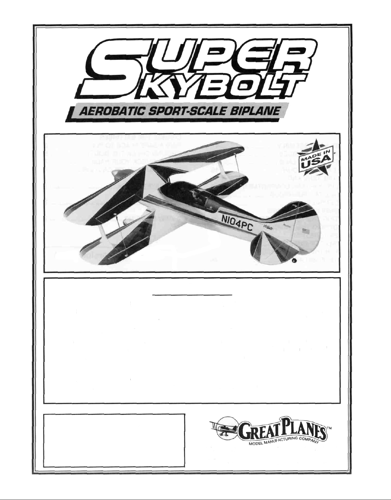
Congratulations and thank you for
purchasing the Great Planes SUPER SKYBOLT'
The skybolt incorporates several new design
features never before found in a biplane kit The
revolutionary wing attachment system makes it
incredibly easy to assemble and disassemble at
the field using only a screwdriver It also features
several new construction techniques that make it
the easiest and straightest building biplane ever!
broken or defective, or if you have any
questions about building or flying this
airplane, please call us at (217) 367-2069
and we'll be glad to help. If you are
calling for replacement parts, please look
up the part numbers and the kit
identification number (stamped on the
end of the carton) and have them ready
when calling.
PRECAUTIONS
The Great Planes Super Skybolt is a high
performance biplane that is modeled after the full
size Skybolt It not only looks beautiful, but it is
also the smoothest and most predictable flying
biplane we have ever flown However, this is not
a beginner's airplane! While the Super Skybolt
is not difficult to build and flies great, we must
discourage you from selecting this kit as your
first R/C airplane It is highly maneuverable, and
lacks the self-recovery characteristics of a good
basic trainer such as the Great Planes PT
Series airplanes On the other hand, if you are
confident with your flying skill and can safely
handle aileron airplanes such as the Great
Planes Ultra-Sport Series or Big Stick Series,
the Super Skybolt is an excellent choice If you
currently fly an aileron airplane, but you are
unsure about your ability to handle the Super
Skybolt, we recommend that you build and fly a
low-wing sport plane first.
1 You must build the plane according to the
plans and instructions. Do not alter or modify
the model, as doing so may result in an unsafe or
unflyable model In a few cases the plans and
instructions may differ slightly from the photos In
those instances you should assume the plans
and written instructions are correct Also, you
may notice a slight difference in length between
longer parts and the plans This is normal and is
caused by the plans expanding and shrinking with
the changing moisture content in the air Do not
modify the parts to fit the plan
2 You must take time to build straight, true and
strong IMPORTANT - Glue should never be
substituted for a good-fitting joint Take a little
extra time to get a good fitting joint and glue it
properly It will be stronger, neater, and much
lighter than a bad joint held together with a glob
of glue!
3-
Page 4
3 You must use a proper R/C radio that is in first
class condition and meets the current AMA and FCC
requirements and the requirements of your local flying
club, the correct sized engine and correct
components (fuel tank, wheels, etc.).
4 You must properly install all R/C and other
components so that the model operates properly on
the ground and in the air.
5. You must test the operation of the model before the
first and each successive flight to insure that all
equipment is operating, and you must make certain
that the model has remained structurally sound.
6 You must fly the model only with the competent
help of a well experienced R/C pilot if you are not
already an experienced and knowledgeable R/C pilot
at this time.
Note: We, as the kit manufacturer, provide
you with a top quality kit and great
instructions, but ultimately the quality and
flyability of your finished model depends on
how you build it; therefore, we cannot in any
way guarantee the performance of your
completed model, and no representations are
expressed or implied as to the performance
or safety of your completed model.
Remember: Take your time and follow directions
to end up with a well-built model that is straight
and true.
OTHER ITEMS REQUIRED
D Four-channel radio with 4 or 5 servos
D Propellers (Top Flite® Power Point™ recommended
- see engine instructions for recommended sizes)
D 2-1/2" (63 5mm)Spinner
D 14 oz Fuel Tank
D Iron-on Covering Material (Top Flite MonoKote®
recommended)
D Fuelproof Paint for wheel pants and cowl
NOTE Top Flite has paint available that matches
Super MonoKote, and is available in convenient
spray cans
D Silicone Fuel Tubing
D 1/16" (1 5mm) thick Wing Seating Tape
D Latex Foam Rubber Padding (Hobbico® 1/4"
recommended )
D Plastic Pilot: Williams Bros. #185 Sport 2-1/2"
Scale
D 2-3/4" (70mm) Main Wheels
D 1-1/4"(32mm)Tail Wheel
D 22 Hinges*
D 2 - Servo extensions (each 24" long) req. for
ailerons on both wings
D 3/32" (2 5mm)Wheel Collars - 2 required for tail
wheel
D #64 Rubber Bands
SUPPLIES AND TOOLS NEEDED
D 2 oz Thin CA Adhesive
D 2 oz Medium or Thick CA Adhesive
D 2 5 oz 15-Minute Epoxy
D Hand or Electric Drill
D Drill Bits 1/16, 3/32", 5/32", 3/16", 1/4", & 19/64"
D Sealing Iron (Hobbico or Top Flite recommended)
D Heat Gun (Hobbico or Top Flite recommended)
D Razor Saw
D Hobby Knife, #11 Blades
D Pliers
D Screw Drivers
D T-Pins
D Straightedge
D Masking and/or Strapping Tape (Required for
construction)
D Sandpaper (coarse, medium, fine grit)*
D T-Bar Sanding Block (or similar)
D Waxed Paper
D Lightweight Balsa Filler ( Hobbico HobbyLite™
recommended)
D Petroleum Jelly (Vaseline)
D IsopropyI Rubbing Alcohol (70%)
D Spray Adhesive (optional) (3M "77")
D Dremel Moto Tool or similar (optional)
*NOTE: There are many types of good hinges on the
market, and everyone has their personal preferences;
therefore, hinges have not been included in this kit.
The current favorite of many modelers is the
laminated hinge that permits hinge slotting with a
hobby knife, and gluing with thin CA adhesive.
*NOTE: On our workbench, we have four 11" T-Bar
sanders, equipped with #50, #80, #700 and #150-grit
We also keep some #320-
grit wet-or-dry sandpaper handy for finish sanding
before covering.
-4
Page 5
DECISIONS YOU MUST MAKE NOW
ENGINE AND MOUNT
The recommended engine for the SUPER
SKYBOLT is a 61* - 90 cubic inch (10 - 15cc)
displacement 2-cycle or a 90 - 1 20 cubic inch
(15-20cc) displacement 4-cycle The
instructions and plans show an OS Max
61(10cc) SF and an OS Max 1 20 (20cc)
Surpass being installed It you are using an
engine other than one of these, be sure to
double check all measurements before gluing or
cutting things that have to do with the engine.
*NOTE: Performance may be marginal if a non-
Schnuerle-ported .60 cu.in. 2-Cycle engine
is used
This kit includes a new Great Planes adjustable
.40 - .70 engine mount (EM4070) that fits most
40 - 61 (2-Cycle) engines and 40 - 70 (4-cycle)
engines If the supplied mount does not fit your
engine, it may be necessary to purchase a
different mount (check with your hobby dealer).
POSSIBLE RADIO
INSTALLATIONS
The Super Skybolt can utilize either one
or two aileron servos We recommend that you
use two aileron servos and build the top wing
with ailerons This is the most maneuverable
configuration and you can always reduce the
control throws to achieve the sensitivity you
desire When using two aileron servos, the
servos are mounted in the bottom wing, directly
in front of the ailerons and control slop is
virtually eliminated If you prefer to use only
one aileron servo, we suggest that you do not
put ailerons on the top wing due to the inherent
top aileron sloppiness The plans show both
methods of construction.
COMMON ABBREVIATIONS USED
IN THIS BOOK AND ON THE
PLANS:
Elev = Elevator
Fuse = Fuselage
LE = Leading Edge (front)
LG = Landing Gear
Ply = Plywood
Stab = Stabilizer
TE = Trailing Edge (rear)
" = Inches
Tri = Triangle
TYPES OF WOOD
GET READY TO BUILD
D 1 Unroll the plan sheets and reroll them inside
out to help them lie flat.
D 2 Remove all parts from the box As you do,
determine the name of each part by comparing it
with the plan and the parts list at the back of this
book. Using a felt tip pen, write the part name or
size on each piece to avoid confusion later Use
the die-cut part patterns shown on page 6 to
identify the die-cut parts and mark them before
punching out Save all leftover pieces. If any of
the die-cut parts are difficult to punch out, do not
force them' Instead, first cut around the parts with
a hobby knife After punching out the die-cut parts,
use your T-Bar or sanding block to lightly sand the
edges to remove any die-cutting irregularities.
BALSA
BASSWOOD
PLYWOOD
D 3 As you identify and mark the parts, separate
them into groups, such as fuse (fuselage), wing,
fin and stab (stabilizer), and hardware.
-5-
Page 6
DIE-CUT PATTERNS
-6-
Page 7
TAIL FEATHERS
BUILD THE FIN AND RUDDER
D 1. Tape the fuselage side view portion of the
plan down onto your flat work surface Tape a
piece of waxed paper over the fin and rudder
portion of the plan.
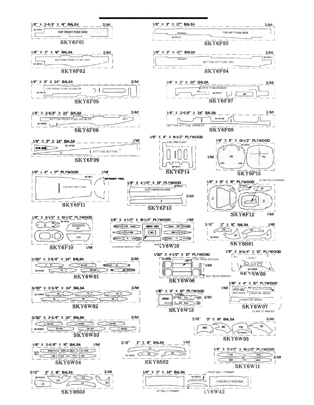
D 2 Working over the plan, cut and assemble the
fin and rudder framework using the die-cut 3/16"
balsa fin and rudder parts (SKY6S01 and
SKY6S02) and the 3/16" x 3/4" x 24" balsa sticks
(SKY6S05) as shown in the photo Sort through
the 3/16" x 3/4" x 24" balsa sticks and pick the
hardest two Use the hardest one later for the
stab trailing edge and use the next hardest one
here for the fin trailing edge Pin the parts in place
over the plan as you assemble them, but be
careful you don't glue the rudder to the fin
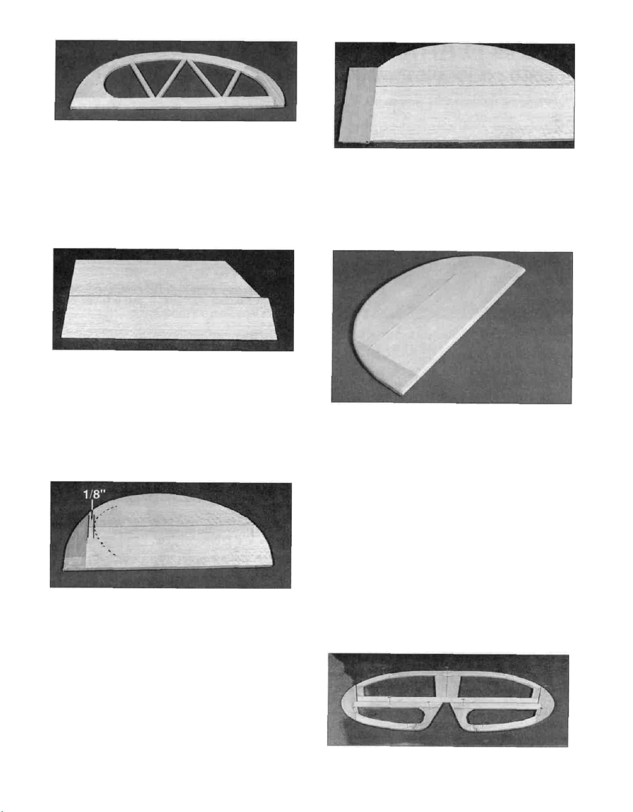
D 5 Using the plan as a guide, cut 3 pieces of
1/16" x 3" balsa from a 1/16" x 3" x 24" balsa
sheet (SKY6S06) to form the fin sheeting as
shown in the photo Glue these together and
quickly wipe off any excess glue with a paper towel
before it cures Sand both sides smooth and then
cut and sand the correct angle into the bottom of
the sheeting so you don't have to cut it after it's
installed on the fin Make sheeting for both sides of
the
fin.
HINT: Use new, sharp sandpaper when sanding
wood with glue joints in it The sharper grit will cut
through the glue much easier and produce better
results than worn out sandpaper
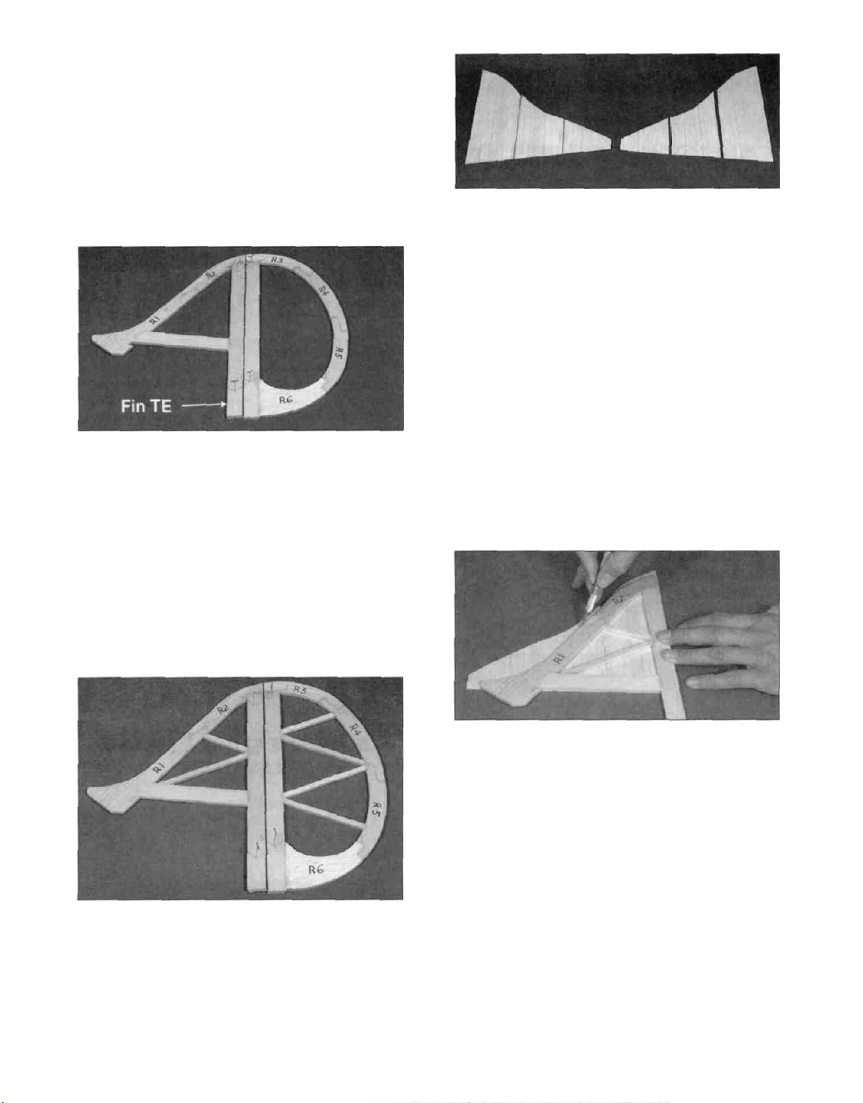
D 3. Cut the fin and rudder "ribs" from the 3/16" x
1/4" x 24" balsa sticks (SKY6S04). Glue these in
place with CA.
D 4. Sand both sides of the fin and rudder
smooth with a fine grit sanding block.
D 6 Glue the sheeting to one side of the fin.
Notice that the grain runs vertical on the fin.
Keep the fin flat while attaching the sheeting After
the side sheeting is installed, trim it flush with the
leading and trailing edges of the fin NOTE: Do not
cut through the sheeting and into the
framework. Always cut into the work surface'
D 7 Glue the other side sheeting in place Be sure
the fin is kept flat until the glue cures Trim and sand
the sheeting flush with the leading and trailing
edges of the framework Carve and sand the
leading edge to a nice rounded shape as shown on
the plans, but keep the trailing edge square.
-7-
Page 8
D 8. Draw a centerline all around the edges of the
rudder. Sand the rudder to a taper as shown on
the fuselage top view. The framework should
end up approximately 3/32" thick at the trailing
edge. Refer to the centerline you drew to keep the
rudder symmetrical.
D 9. Using the plan as a guide, cut a 1/16" x 3" x
24" balsa sheet (SKY6S06) in half to form the
rudder sheeting as shown in the photo. Glue
these together and sand both sides smooth. Make
sheeting for both sides of the rudder. Cut one end
of the sheeting perpendicular to a long edge.
D 12. Cut two 4" long pieces of 1/16" x 1-3/8"
balsa sheeting from the 1/16" x 1-3/8" x 24" hard
balsa sheeting (SKY6S07). Glue these to both
sides of the rudder next to the sheeting on R6.
D 13. Use a sanding block with medium (150) grit
sandpaper to sand both sides of the rudder
smooth. Carve and sand the rudder trailing edge to
a nice rounded shape and the leading edge to a
"V" shape as shown on the plan.
D 10. Glue the sheeting to one side of the rudder
so the perpendicular edge overlaps onto R6
approximately 1/8". The rest of R6 is not sheeted
until later. Keep the rudder flat while attaching the
sheeting. After the sheeting is installed, trim it flush
with the outside edges of the framework.
D 11. Glue the other side sheeting in place so that
it too only overlaps approximately 1/8" onto R6. Be
sure the rudder is kept flat until the glue cures.
Trim and sand the sheeting flush with the leading
and trailing edges of the framework.
BUILD THE STABILIZER AND
ELEVATORS
D 1. Tape the fuselage top view portion of the
plan down onto your flat work surface, and cover
the stabilizer portion of the fuselage top view with
wax paper.
D 2. Assemble the stab and elevator framework
over the plan, using the die-cut 3/16" balsa stab
-8-
Page 9
parts (SKY6S02 and SKY6S03) and the 3/16" x
3/4" x 24" balsa sticks (SKY6S05) Use the
hardest 3/16" x 3/4" stick for the stab trailing edge
Pin the parts in place over the plan as you
assemble them but be careful not to glue the
elevator to the stab
D 3 Cut the stab and elevator "ribs" from the
3/16" x 1/4" x 24" balsa sticks (SKY6S04) Glue
these in place with CA.
D 4 Use a sanding block with medium (150) grit
sandpaper to sand the edges and both sides of
the stab and elevator smooth Carefully draw a
centerline all around the edges of the stab and
elevator This will make it easier to maintain
symmetry when sanding later.
D 7 Glue the other side sheeting in place Be
sure the stab is kept flat until the glue cures Trim
and sand the sheeting flush with the leading and
trailing edges of the framework NOTE: It is
essential to get a strong and complete bond
between the stab sheeting and the stab
framework, especially in the center, therefore,
we recommend using 30 minute epoxy when you
apply the last piece of sheeting Spread the epoxy
evenly but sparingly on the structure, to avoid
excess weight
D 8 Carve and sand the leading edge to a nice
rounded shape as shown on the plans, but keep
the trailing edge and the tips square
D 5 Glue two 1/16" x 3" x 24" balsa sheets
(SKY6S06) together (edge to edge) to form one
piece of stab sheeting Sand or trim the edge of
the sheets before gluing to obtain a good joint
between the two, without any gaps After the glue
is cured, sand both sides of the sheeting with a
fine grit sanding block Make sheeting for both
sides of the stab.
D 6 Thoroughly glue the sheeting to one side of
the stab Keep the stab flat while attaching the
sheeting After the sheeting is installed, trim it flush
with the edges of the stab.
D 9 Using a sanding block and coarse (80-grit)
sandpaper, sand both sides of the elevators to a
taper (see cross section on plans) The trailing
edge should end up approximately 3/32" wide
D 10 Cut four 1/16" x 2-5/8" x 24" balsa sheets
(SKY6S08) in half to form eight 12" long pieces
Glue these 12 sheets together to form four 5-1/4"
wide sheets Cut one end of each sheet so it is
perpendicular to the long edges Sand both sides
of these sheets smooth.
-9
Page 10
D 11 Glue one 5-1/4" sheet to each elevator at
the angle shown on the plans and in the photo so it
overlaps onto S-6 approximately 1/8" Cut a corner
off the unused end of the sheet, and glue it at the
front tip of the elevator Trim the sheeting flush with
the edges of each elevator.
D 12 Glue the remaining sheeting in place on the
other side of each elevator so that it too overlaps
only approximately 1/8" onto S-6 Be sure the
elevator is kept flat until the glue cures Trim and
sand the sheeting flush with the edges of
the framework
TEMPORARILY INSTALL HINGES
D 1 Using the plan as a guide, mark the hinge
locations on the stab, elevators, fin and rudder
Designate one side of the stab as being the top and
one elevator as being "right" and the other as "left".
CAUTION!!!: You must use extreme care
when cutting hinge slots with a hobby
knife, to avoid cutting yourself! If the
balsa part breaks while you are pushing
on the knife, the blade could go into your
hand before you know it! A good
precaution is to wear leather gloves while
performing the following steps.
D 13 Cut four 4" long pieces of 1/16" x 1-3/8"
balsa sheeting from what is left of the 1/16" x
1-3/8" x 24" hard balsa sheeting (SKY6S07) Glue
these to both sides of each elevator, next to the
sheeting that stops at S-6
D 14 Sand the leading edge of the elevators to a
"V-shape" as shown on the plan Round off the
tips and the trailing edge, but keep the inside edge
(marked with an arrow) square
D 2 Cut the hinge slots on the centerlines you
drew earlier Our recommended hinge slotting
method is described below.
A Begin by carefully cutting a very shallow slit at
the hinge location The first cut is to establish
your cut in the right place, so concentrate on
staying on the line and don't cut too deeply.
B Make three or four more cuts in the same line,
going slightly deeper each time. As you make
these additional cuts, work on going straight
into the wood Continue this process while
"wiggling" the knife handle forward and
backward until the blade has reached the
proper depth for the hinge
C. Trial fit the hinge into the slot If the hinge is
difficult to push in, re-insert the knife and move
it back and forth in the slot a few times to
enlarge the slot Do not glue the hinges yet.
10
Page 11
D 3 Refer to the plans and mark the location of
the tailgear (WBNT128) on the rudder Drill a 7/64"
hole in the rudder (the hole is drilled slightly
oversize to allow for positioning, and to create a
hard epoxy sleeve" around the wire) Then groove
the rudder leading edge to accept the tailgear wire
and the nylon bearing Mark the location of nylon
bearing on the fin and cut a slot for it.
FUSELAGE
ASSEMBLY
PREPARE FUSE SIDES
D D 1 Working over the fuselage side view
covered with waxed paper, trial fit a die-cut 1/8"
balsa top front fuse side (SKY6F01), and bottom
front fuse side (SKY6F02) together, sanding
slightly if necessary for a good fit Make sure they
line up with the plans, and glue them together
HINT: Using a hobby knife, sharpen the inside of
one end of a 1/8" diameter tube, and use it to cut
the groove in the leading edge of the rudder (and
ailerons if applicable)
D D 2 Trial fit a die-cut 1/8 balsa top aft fuse
side (SKY6F03) and a die-cut 1/8" balsa bottom
aft fuse side (SKY6F04) together Sand them
slightly if necessary to achieve a good fit, and
glue them together.
D D 3 Test fit the aft fuse side half in place
behind the front fuse side half Sand the two
halves if needed to get them to fit together tightly
and match up with the plans Glue them together
with CA Then sand both sides smooth with a
sanding block
D 4. Trial fit all these parts together using the
hinges Sand the aerodynamic balance" part of
the elevators to get them to match up with the
stab Do not glue the hinges until after covering
the surfaces.
D D 4 Working over the fuselage side view still
covered with waxed paper, trial fit a die-cut 1/8" balsa
top front fuse doubler (SKY6F05), and bottom
front fuse doubler (SKY6F06) together, sanding
slightly if necessary for a good fit Make sure they
line up with the plans, and glue them together.
11
Page 12
D D 5. Trial fit a die-cut 1/8" balsa top aft fuse
doubler (SKY6F07) and a die-cut 1/8" balsa
bottom aft fuse doubler (SKY6F08) together.
Sand them slightly if necessary to achieve a good
fit, and glue them together.
D D 6. Test fit the aft fuse doubler half in place
behind the front fuse doubler half. Sand the two
halves if needed to get them to fit together tightly
and match up with the plans. Glue them together
with CA, and sand both sides of the doubler
smooth with a sanding block.
ASSEMBLE THE FUSELAGE
D 1. Trial fit the die-cut 1/8" ply formers F3, F4
and F5 (SKY6F10 and SKY6F12) to make sure
they fit into the appropriate slots in both fuselage
sides. If there is any excess glue in any of the fuse
doubler slots, clean it out with a hobby knife. If it is
necessary to trim any of the formers, be sure to
trim both sides of the formers the same amount to
keep them symmetrical.
D D 7. Position the doubler on top of the fuse
side and align their bottom and front edges. Glue
the doubler to the fuse side by applying thin CA
around all edges of the doubler, including the
lightning holes. Use plenty of thin CA to allow it to
wick into the joints as far as possible.
D D 8. Inspect all glue joints for gaps and add
thick CA if necessary to strengthen the joints.
D 9. Repeat the above steps to make another
fuse side and doubler. When gluing the doubler
to the fuse side, make sure you assemble a
RIGHT and a LEFT set of sides!
D 10. Place the two assembled fuse sides
together. Sand the edges as necessary to make
the two sides identical. Also sand the sides of
each assembly smooth with a fine sanding block.
D 2. Assemble formers F3, F4 and F5 between
the two fuse sides and use masking tape to pull
the fuse sides together. Make sure all the tabs are
seated in their notches, and add a drop or two of
thin CA to the top notches of each former. Use only
as much glue as required to tack things together.
We will come back and securely glue everything in
a few steps.
D 3. Fit the die-cut 1/8" ply belly former (BF)
(SKY6F12) into its notches to make sure it seats
all the way into the notches. Pull the fuse sides
together and glue the belly former into place.
Masking tape can be used to hold the fuselage
together while the glue cures.
12
Page 13
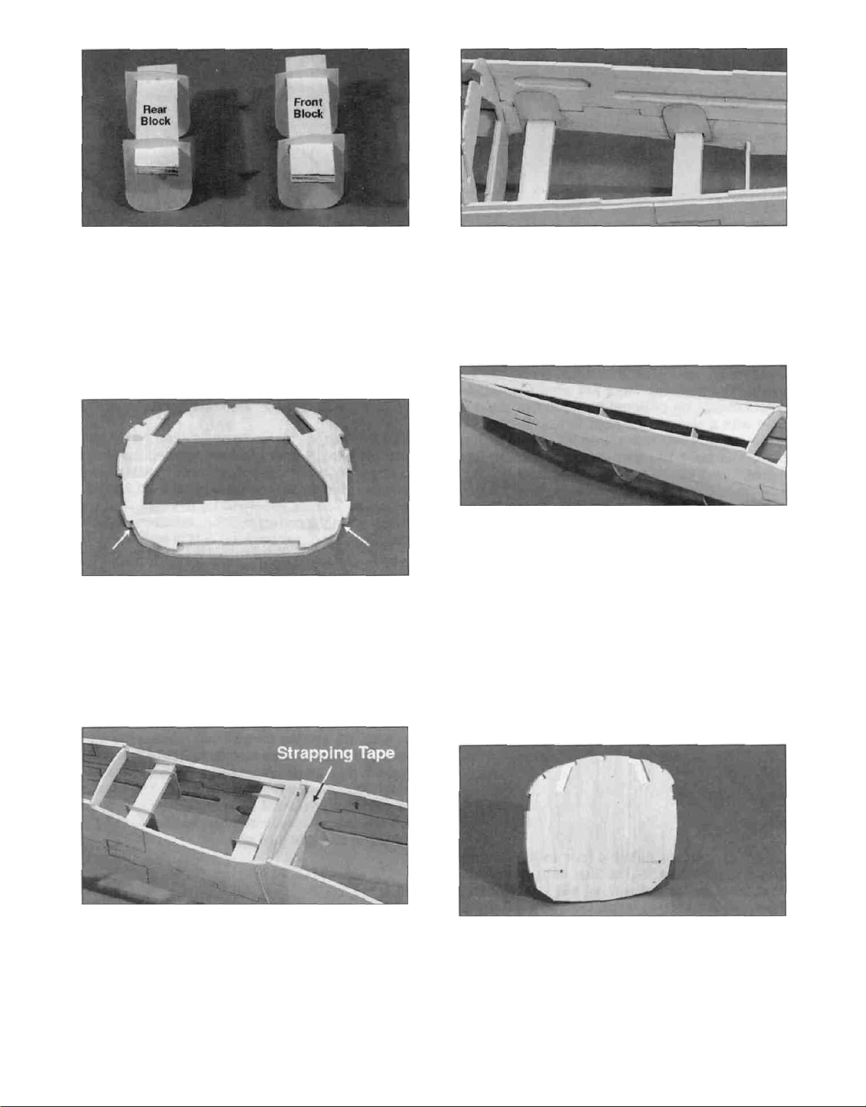
D 4. Slide two die-cut 1/32" ply bolt block braces
(SKY6W06) onto both the 1/4" ply front and rear
wing bolt blocks (SKY6F20 and SKY6F21). Notice
that the slant on the braces is at the front of the
rear block and the rear of the front block to clear
the wing saddle. The photo clearly illustrates this.
D 5. Glue die-cut 1/8" ply former LG2 (SKY6F10)
to one side of the die-cut 1/8" ply former F2
(SKY6F12) with thick CA. The bottom of the
interlocking tabs on both formers should line up as
shown in the photo.
D 7. Slide the 1/32" ply braces out against the
fuse sides and securely glue them in place with
thick CA or epoxy.
D 8. Glue the die-cut 1/8" balsa aft fuse bottom
(SKY6F09) in place with thin CA. The aft tip of the
bottom should be centered on the fuselage sides
and glued in place. The bottom will automatically
keep the aft portion of the fuselage straight. Go
over all the glue joints at formers F3, F4 and F5
and securely glue the fuse sides to the formers
with thin and then thick CA.
D 6. Position former F2 into place and apply CA
near the top notches. Carefully slide both wing bolt
blocks into their respective slots. Pull the fuse
sides together at the bottom of the former and use
strapping tape to hold them tightly against the
former. Make sure the bolt blocks are seated in
their notches, and apply thin CA around the blocks
and the former notches.
D 9. Use thick CA or epoxy to glue the die-cut 1/8"
ply formers F1A and F1B (SKY6F15) together to
form the firewall. NOTE: The embossed centerlines
must be showing on F1A. The interlocking tabs on
both formers should line up. . . but former F1B is
slightly larger than F1A, so just center it on F1A.
Wipe off any excess glue before it cures.
13
Page 14
D 10 F1A has four lines embossed on it The two
short lines are the actual horizontal center of the
former The two crossing lines are offset to the left
(as viewed from the pilot's seat) of the horizontal
center to automatically put the spinner in the
center of the cowl when right thrust is built into the
plane The crossing lines are what the engine
mount should be centered on since this plane is
built with 2 degrees of right thrust Center the
engine mount on these lines as shown on the
plan, and mark the bolt locations through the
mount Drill 5/32" holes at the bolt locations
NOTE: This kit includes the new Great Planes
EM4070 Adjustable Engine Mount. To properly
position the mount, just slide the mounting
beams together and center the beams over the
embossed lines when marking the mounting
holes. There are "tick" marks on the side of the
mount to help you position it vertically.
D 11. If you are using a four cycle or other
engine/mount combination that does not require
four 9mm engine spacers but will use 6-32 blind
nuts, you will need to install the 1/8" x 2-3/4" x 23/4" plywood back plate (SKY6F31) on F1B.
Center it over the 5/32" holes and glue it in place.
Drill 5/32" holes through the back plate using the
holes you drilled earlier as guides NOTE If you
are using another engine mounting system, such
as vibration isolation type mounts, you may not
need the back plate The photos show a typical
.60-size glass filled mount being used.
6-32 Blind Nut
6-32 X 2-1/2" Machine Screw
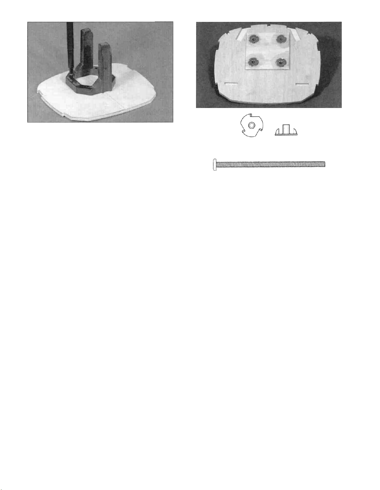
D 12 Press the four 6-32 blind nuts (NUTS003)
into the firewall from the back and tap them into
place with a hammer Temporarily attach the
engine mount to the firewall with the 6-32 x 2-1/2"
machine screws (SCRW071) to make sure the
holes are in the correct position Adjust the holes if
necessary, and glue the blind nuts in place.
D 13. Wet the outside of the fuselage sides from
F2 forward with water to help it bend around the
formers Test fit the die-cut 1/8" ply fuel tank floor
(SKY6F14), die-cut 1/8" ply former LG-1
(SKY6F10) and the firewall into place in the front
of the fuselage Notice that the fuel tank floor helps
set the right thrust and appears to be cut crooked
until you get everything assembled The firewall
should touch the front edge of the fuse side notch
on the left fuse side and the back edge of the
notch on the right fuse side.
The easiest way to assemble these parts is as
follows
D A Snap the back of the fuel tank floor into
its notches
NOTE: The tank floor when in position correctly,
should cause the firewall to slant to the RIGHT.
14
Page 15
D B Tack glue the tab on the top of LG1 into the
fuel tank floor.
D C Tack glue the firewall onto the front of the
fuel tank floor
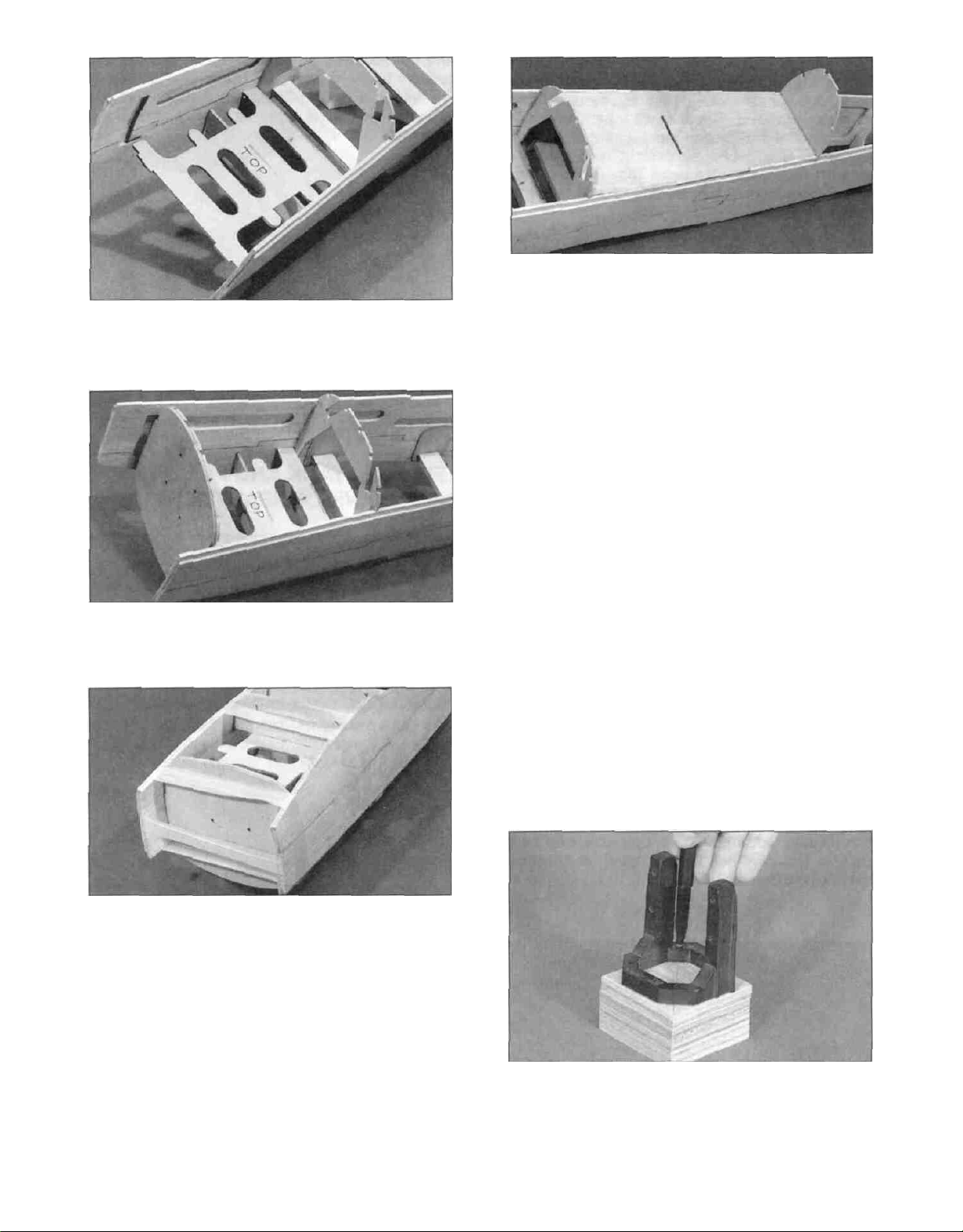
D 14 Snap the die-cut 1/8" ply cockpit bottom
(SKY6F11) in place by inserting the rear tab into
F3 and carefully sliding the front tab down into
place in F2 Glue the cockpit bottom to the fuse
sides and the formers.
Note: The engine mount shown in the
following photos may not be the mount
supplied in this kit.
D 15 Glue the required number of 9mm (3/8")
engine mount spacers (SKY6F27) together as
shown in the next photo You can lay your
engine/mount combination over the plans and
determine where the engine should be placed on
the mount and how many spacers should be used
We have determined that the following engines
usually require
D D Pull the fuse sides together and use
strapping tape to hold everything together
Securely glue everything in place with either epoxy
or CA If you are going to use CA, you can tape
everything first and thoroughly saturate the joints
with thin CA Then apply a generous bead of thick
CA around each joint
D E Included you will find a piece of 1/4" balsa
triangle for you to install on the back of the firewall
It should be pressed into the corners formed by the
fuse sides and the firewall.
The OS 61 SF requires 3 spacers
The OS 91 Surpass requires 1 spacer
The OS 1.20 Surpass requires no spacers
D 16 Center the engine mount on the face of the
spacers and mark where to drill the mounting
holes Drill 3/16" holes straight through all the
spacers you glued together (a drill press will be
helpful for this, if you have access to one)
15-
Page 16
D 17. Mount your engine to your mount following
the manufacturer's recommendations. Refer to the
plans to make sure you get the engine positioned
far enough forward. The distance from the front of
the firewall to the front of the engine thrust plate
should be approximately 6-1/16" for a spinner
without overhang. Remove the engine. The
following instructions explain how to work with the
mount supplied.
DRILL ENGINE MOUNT
(Great Planes EM4070 or similar glass-filled mounts)
D 1. Hold the engine pointing straight ahead on
the mount (in the approximate location shown on
the plans) and mark the mounting hole locations
on the mount. At the marked locations, accurately
drill 7/64" (or #36) holes. NOTE: If you have
access to a drill press, use it for drilling these holes
to insure that they are drilled vertically.
and the required number of spacers. Glue the
spacers to the firewall and screw your engine to
the mount. If the 2-1/2" screws protrude into the
fuel tank compartment, cut them off flush with the
blind nuts.
FIT FUEL TANK AND FUELPROOF
TANK COMPARTMENT
D 2. Now you may use one of the following
methods to attach your engine to the mount:
#6 X 3/4" Sheet Metal Screw
Method 1: Screw the #6 x 3/4" sheet metal
screws (provided in the kit) through the engine
mounting flange and into the mount. When first
installing these screws, put a drop of oil into each
screw hole.
Method 2: Cut threads into the holes you just
drilled using a 6-32 tap and tap wrench. If you use
this method, you'll have to supply your own bolts
(6-32 x 1" socket head cap screws) for attaching
the engine to the mount.
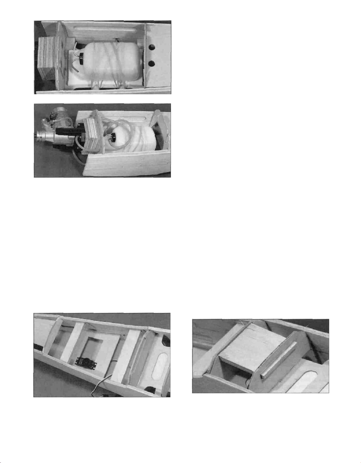
D 1. Cut a piece of 1/4" thick latex foam (not included)
into a 3" x 6" rectangle. Glue it to the ply tank floor to
help keep the fuel tank from vibrating excessively.
D 3. Attach the engine mount to the firewall using
the 6-32 x 2-1/2" machine screws (SCRW071)
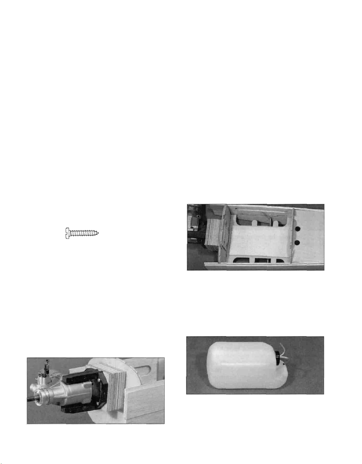
D 2. Assemble your 14 oz. fuel tank according to
the tank and engine manufacturer's instructions.
HINT: To avoid kinking the tubes when bending,
use K&S Tubing Bending Springs. We routed
the fuel and vent tubes as shown in the photo. This
helps keep the fuel tubing from getting kinked.
-16-
Page 17
possible. Make sure you will still be able to install
and work on the servo linkages. These servo
positions are not critical, but will help you balance
the plane without using extra weight. The die-cut
1/8" ply servo tray (SKY6W10) is designed to fit in
the doubler lightening hole for most installations,
but will have to be cut down in width to fit towards
the rear of the plane. It can be glued just below
the lightening hole when it needs to be installed
farther forward as shown in the photo. Check your
servos to make sure they will fit into the tray and
are not held off the tray by the cockpit bottom.
Securely glue the tray in place.
D 3. Install the fuel tank using four #64 rubber
bands (not included) as shown in the photo.
Determine where the fuel and vent tubes should
pass through the firewall to match up with your
particular engine. Drill a 1/4" hole for each tube to
pass through the firewall. The larger holes will
allow you to seal around the tubes with silicone
bathtub sealer. Install the fuel tubing, but be sure
to leave a couple extra inches for good measure.
Mark on the front of the firewall which tube is fuel
and which is the vent.
D 5. Determine the location where the throttle
pushrod (not included) will pass through F1.
Normally, a solid wire pushrod will work fine for the
throttle pushrod. Drill a 3/16" hole (or whatever
size you need) in the firewall for the throttle
pushrod guide tube. Cut the outer guide tube to
length and roughen the outside of the tube with
medium grit sandpaper. Slide the tube into place
and glue it with thin and then thick CA. Refer to the
plans to get an idea of how to route the pushrod.
D 4. Determine where your servos should be
mounted. If you are using a lighter engine (.61 .75 2-cycle) the servos should go as far forward as
practical. If you are using a heavy engine (1.20
4-cycle) the servos should go as far back as
D 6. Locate the 1/4" x 2-3/4" x 3" ply landing
gear plate (SKY6F30) and test fit it in place
between LG-1 and LG-2. NOTE: The grain
should run from LG-1 to LG-2. Enlarge the slots
if necessary to get the plate to fit. When satisfied
with the fit, securely epoxy the plate in place.
17-
Page 18
D 7. Cut the 3/16" x 2" x 18" balsa sheet
(SKY6F24) in half and glue the two 9" pieces
together to form a 4" wide bottom nose sheet.
Center the 4" wide sheet over the bottom of the
fuselage nose and glue it to formers F2 and LG1
first. It should extend 1/16" behind F2 and the rest
should extend forward of the firewall. Use a piece
of strapping tape to hold it in place while the glue
cures. Wet the outside surface of the nose bottom
and allow it to soak in for 5 minutes or so to help it
bend easier. Apply a generous bead of thick CA to
the bottom edge of the firewall. Then bend the
sheeting into place and hold it with another strip of
strapping tape. Apply thin CA and then another
bead of thick CA around each former before
removing the tape. This gluing process makes very
strong joints because the thin CA soaks in and
holds the wood together and the thick CA forms
fillets for extra strength.
D 9. Cut the 1/4" x 1-3/4" x 18" balsa bottom
nose corner (SKY6F25) sheet in half to make two
9" long pieces. Glue these pieces in place on each
side of the nose as shown in the photo.
D 10. Use your razor plane and a sanding block to
rough carve the corners to shape. Refer to the
cross sections on the fuselage plan during this
step. Cut the fuselage bottom and the corners off
even with the front edge of the fuse sides and the
wing saddle.
D 8. Remove the strapping tape and use a razor
plane and a sanding block to shape the edges of
the bottom and the fuse sides to match the bevel
of the formers.
INSTALL TAIL PUSHRODS
D 1. Install the elevator, rudder and throttle servos
using the screws that came with the servos. Screw
18-
Page 19
Nylon Clevis
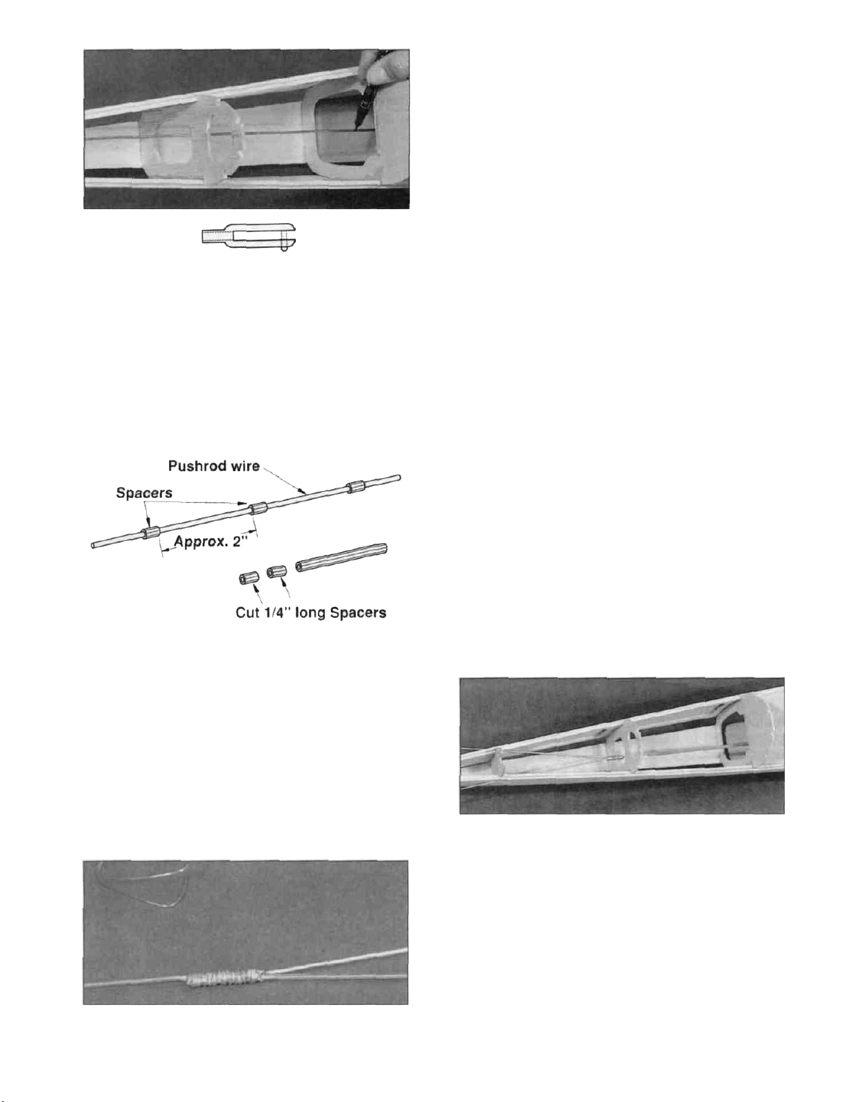
the plan These will make the "Y" part of the
elevator pushrod. Lay the two 12" wires on the
plan so they are lined up with the ones drawn Lay
the forward pushrod wire on top of the two 12"
rods and tack glue the three together with a drop
of CA Wrap the pushrod junction with the silver
wrapping wire (WIREST15) provided in the kit
and securely solder the three pushrod wires
together A good solder joint is necessary here, so
follow the hints given below.
a nylon clevis (NYLON17) about 1/2" onto one of
the 34" threaded wires (WIRES17) Hook up the
clevis to the elevator servo and, with the servo arm
in its neutral position, use a fine tip permanent
marker to accurately mark where the pushrod wire
goes through formers F3 and F4.
D 2 Lay the 34" wire down over the fuselage top
view and line up the marks you made with the F3
and F4 formers on the plan Cut the 34" wire off
where the plans show it ending, to make the
forward part of the elevator pushrod Cut four 1/4"
long yellow pushrod spacers from the 6-1/2" long
inner pushrod piece (PLTB004) Slide these
spacers onto the pushrod wire and position them
near the threaded end until after the soldering
operation.
SOLDERING HINTS
A Roughen the area to be soldered with fine
sandpaper Then thoroughly clean the items to
be soldered with alcohol or degreasing solvent.
B. Apply a small dab of soldering flux.
C Heat the metal with a soldering gun or iron, and
apply the solder to the metal, not the iron The
metal must get hot enough to melt the solder,
and the solder must freely flow into the joint.
D. Do not move the parts until the solder has
cooled
E. Clean off the excess flux with alcohol or solvent
and test the joint for strength.
D 3 Bend two 12" pushrod wires (WIRES16) 1"
from the unthreaded end to the angle shown on
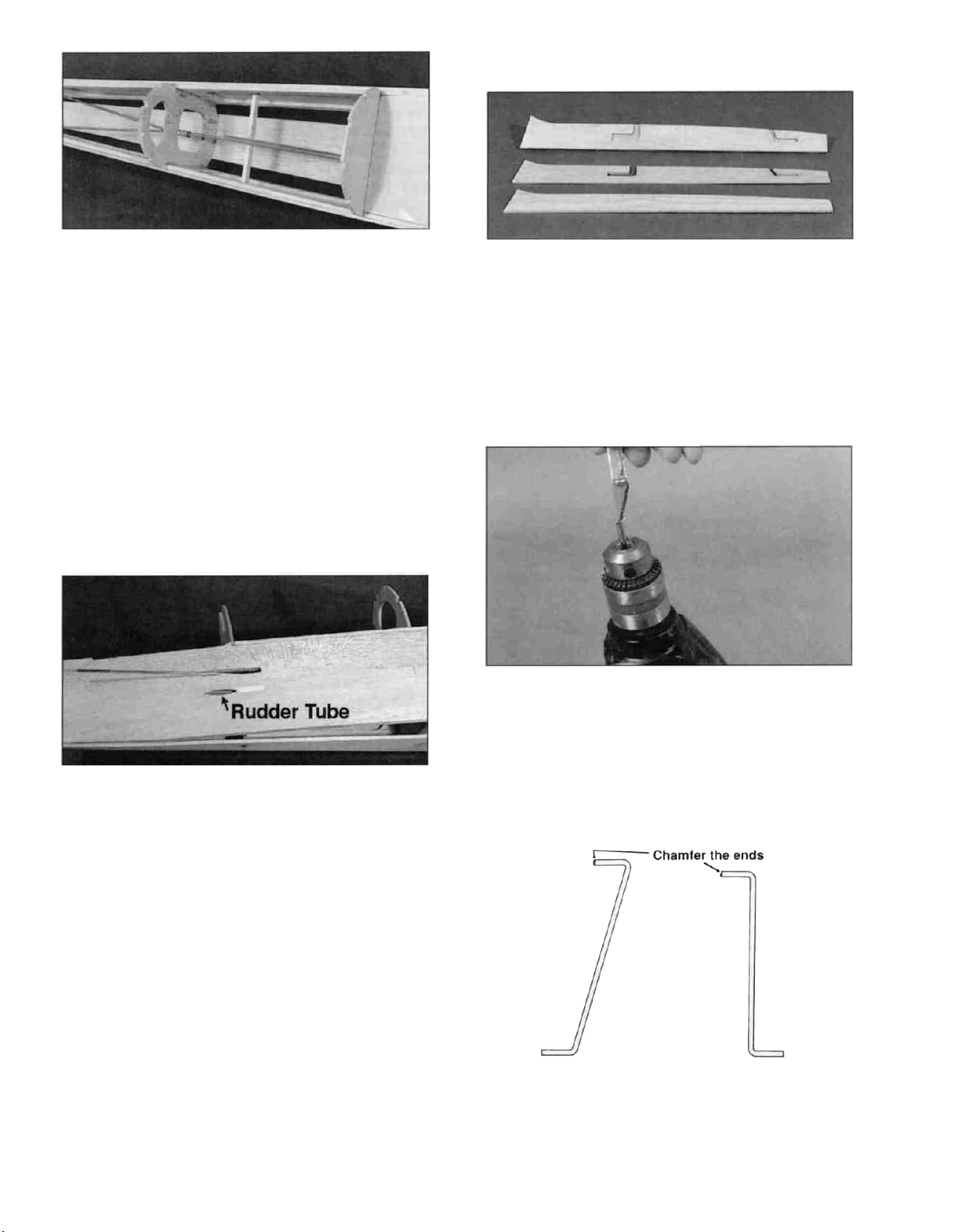
D 4 Cut a piece of pushrod outer tube
(PLTB002) 10" long and scuff the outside of the
tube with sandpaper Slide the 1/4" inner spacers
near the middle of the elevator pushrod wire and
space them about 2" apart Remove the nylon
clevis from the servo end of the elevator pushrod
and slide the 10" long outer tube onto the pushrod.
Install the pushrod in the fuselage by inserting the
servo end through former F4 and sliding it forward
until the "Y" will slip down into the fuselage Then
back the pushrod out the top set of exit slots.
Screw the nylon clevis back onto the servo end of
the pushrod and hook it up the servo arm.
19-
Page 20
D 5 Cut a scrap piece of balsa to fit about 2" in
front of the pushrod "Y" junction and glue it in
place This will be a pushrod brace and both the
elevator and rudder pushrod outer tubes will be
glued to it Glue the elevator pushrod guide tube to
the top of the brace so the end of the guide tube is
approximately 1-1/2" away from the solder joint
Operate the servo horn by hand to make sure all
the inner spacers stay inside the guide tube
throughout the elevator operation range Make
another balsa brace to go near the servo end of
the guide tubes and glue it in place.
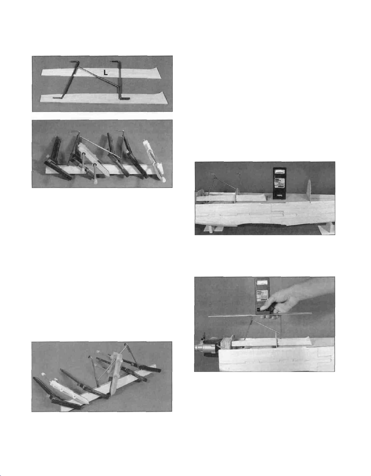
ASSEMBLE THE CABANES
D 1 Punch out the die-cut 1/8" ply cabane wire
holders (SKY6F13) and glue an "L" side to one of
the center pieces Glue an "R" side to the other
center piece Notice that the "L" (left) sides are 1/8"
longer than the right side. This is to allow for the
engine right thrust.
D 6 The rudder pushrod guide tube should be
installed now Cut it to fit from the lower right
pushrod exit to the front pushrod brace Scuff the
outer surface of the tube with sandpaper Allow the
tube to extend past the pushrod exit a few inches
and securely glue it in place After the glue has
cured, cut the tube off flush with the fuselage side.
Use HobbyLite filler to fill around the rudder pushrod
cut-out You can also fill the other rudder cut-out on
the left fuselage side When the filler is dry, sand it
and the pushrod flush with the fuse side.
D 7 If you would like to install an extra pushrod
tube in which to route the receiver antenna, now is
a good time to do it Just drill holes where
necessary and securely glue it in place.
D 2.Use a hobby knife to chamfer the front end of
each 5/32" OD x 3/4" brass tube (BRST021) If
you have a hand drill with a relatively slow speed,
you can chuck the tube in the drill to do this Vary
the angle of the knife blade during this process to
obtain a nice rounded chamfer.
D 3 Locate the 1/8" front and rear left side
cabane wires (WBNT177 and WBNT179) These
are going to slide into the 5/32" OD brass tubes so
their ends need to be smoothly chamfered Use
some very fine (600 grit) sandpaper to smooth out
-20
Page 21
the front of each wire so it will easily slide into the
tube. Test fit the tubes onto the wires.
D 4. Test fit the two left side cabane wires and a
1/8" middle cabane wire (WBNT178) in place in
the die-cut grooves of the Left holder to make sure
they fit correctly. Remove the wires, scuff up the
lower ends with sandpaper and clean them with
alcohol to remove any oils. Spread epoxy in the
grooves and replace the wires. Add more epoxy on
top of the wires and on the center holder. Install
the other "L" side and tightly clamp the assembly
together until the epoxy cures. Make sure the wires
stay properly oriented while the glue is curing. Do
not worry about the bends being perfect. We will
"tweak" them later. You may also notice that the
wires are slightly thicker than the wood. This is due
to manufacturing tolerances in the wood. If this is
the case, just make sure you use enough epoxy to
fill the gaps. Wipe any excess epoxy off the
assembly with a paper towel and alcohol.
assembly to the same length as the sides. Do not
sand into the wood on the bottom of the
assemblies, though, as they are designed to
automatically set the top wing incidence.
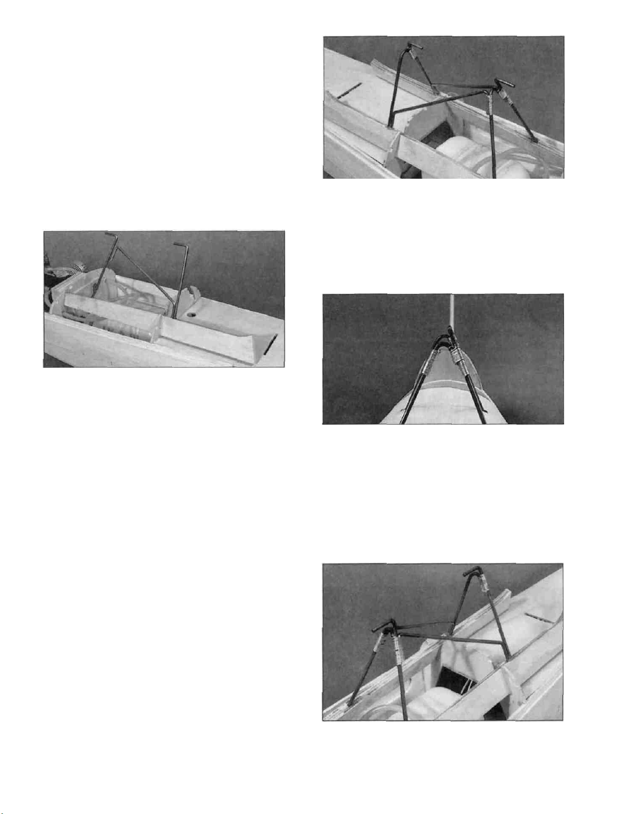
SETTING THE TOP WING
INCIDENCE
D 1. You need to check the top wing incidence
before gluing the cabane holders in place. To do
this, temporarily install the left cabane strut. You
will need an incidence meter or a level.
D 2. Block the fuselage up until the cockpit sides
are level.
D 5. Build the right side cabane assembly
using the same procedure outlined above. When
both the right and left cabane assemblies are
cured, carefully sand the edges to remove any
excess glue. Sand the center piece of the right
D 3. With the cabane holder fully seated in its
notches, check to make sure the horizontal parts of
the cabane wires are directly over the center of the
fuselage. If necessary, tack glue the holder in
place and carefully put a level or incidence meter
across the cabane wires. The top wing should
have 1 degree of NEGATIVE incidence (front wire
1/16" lower). Adjust the position of the holder in its
slots, if necessary, until the incidence is correct.
You can do this by cutting the notch in F1B lower
-21
-
Page 22
to allow the front end of the holders to drop. If you
have to raise the aft end of the holders off the
cockpit bottom to set the incidence, you should
glue scrap wood in the space between the holder
and the cockpit bottom. When you have it correctly
positioned, make a mark on the formers and the
holder so it can be accurately replaced. Normally,
the incidence will be correct when the holder is
bottomed out in both the notches. If it does not
seem to be correct, start over and re-check
everything before continuing. NOTE: When
using a level, the incidence is correct if you put a
scrap of 1/16" balsa between the level and the
front cabane wire and the level is level.
A. Wrap the front right joint first.
B. Wrap the front left joint second. The right wire
goes on the right side of the left front wire, and the
left middle wire goes behind the left front wire.
C. Wrap the rear wires together.
D 4. Epoxy the left cabane holder in place,
making sure any marks you made are lined up. Be
sure to glue the holder to both the formers and the
cockpit bottom.
D 5. Test fit the right holder in place and insert the
die-cut 1/8" ply instrument panel (SKY6F11) in its
slot to make sure it will fit. If the aft end of the
cabane holders get in the way, sand them until the
panel will fit. Also check the bends of the right
front and right rear cabane wires to make sure
they will be tangent to the left wires. If not, bend
them with pliers until they are.
D 6. Epoxy the right cabane holder in place. Don't
worry if the wires don't match up perfectly, as they
will be joined later. Be sure to glue the holder to
both formers and the cockpit bottom. Scrape any
excess epoxy off of the cabane wires.
SOLDERING THE CABANE WIRES
TOGETHER
D. Temporarily slide the fin into place on the
fuselage. Sight down the two horizontal wires
and check to make sure they are in line with
each other and the fin. If not, adjust the
wrappings or bend the wires if necessary to get
them straight (wrap the wire with a cloth first to
prevent scratching).
D 1. First, clean all the wires with alcohol to
remove any oil. Attach the wires to each other in
the following order by wrapping the joint with the
silver wire provided and soldering the joint with
acid core solder. NOTE: It is easier to get a good
looking solder joint if the wire is wrapped tightly
and uniformly around the wire.
D 2. Solder all three joints together. You will need
at least a 250 watt soldering iron or preferably a
propane torch. Make sure you get good solder flow
on all three joints.
-22-
Page 23

INSTALL TOP SHEETING
D 1. Glue the die-cut 1/8" ply instrument panel
(SKY6F11) in place against the cabane holders.
D 4. Cut the three remaining stringers from the 3/16"
sq. x 24" balsa sticks to fit between the instrument
panel and the firewall. Glue them in place.
D 2. Glue the die-cut 1/8" balsa cockpit back
(SKY6F07) in place against former F3. Sand the
edges flush with the sides of the former.
D 3. Install the two outer 3/16" sq. stringers by
cutting two 3/16" sq. x 24" balsa sticks (SKY6F26)
to fit between F1 and F3 and gluing them in place.
D 5. Test fit the 3/32" x 2-3/8" x 14" balsa top
center sheet (SKY6F22) in place between the
cabane wires. It should fit from the center of one
middle stringer to the center of the other middle
stringer. Sand it if necessary to fit between the
cabane wires. Glue it in place with CA.
D 6. Cut two 3/32" x 2-5/8" x 24" balsa nose side
sheets (SKY6F23) to fit around the cabane wires
and instrument panel. A pattern is provided on the
plans to give you a starting place. Note: When
using this pattern please leave 3/8" extending past
the slanted edge where the instrument panel will
be. You may have to modify the sheets of balsa to
get them to fit your particular model nicely. A good
method to cut parts from patterns is to use spray
adhesive (3M 77 spray adhesive works well) to
attach the pattern to the wood and then pin the
required number of parts underneath the sheet
with the pattern on it. You can then cut the parts
out with a hobby knife or a jig saw. Naphtha (lighter
fluid) works well to remove the spray adhesive
from the parts.
-23-
Page 24

D 7. Test fit the nose side sheets in place and
sand them if required to get a good fit. Glue the top
edge of the side sheet to the middle stringer and
the center sheet. Do not attempt to bend the
sheeting into place yet.
D 11. The sheeting around the cockpit should be
trimmed even with the side stringers and model
filler should be used to fill in around the instrument
panel so dirt will not get into the canopy after the
model is finished.
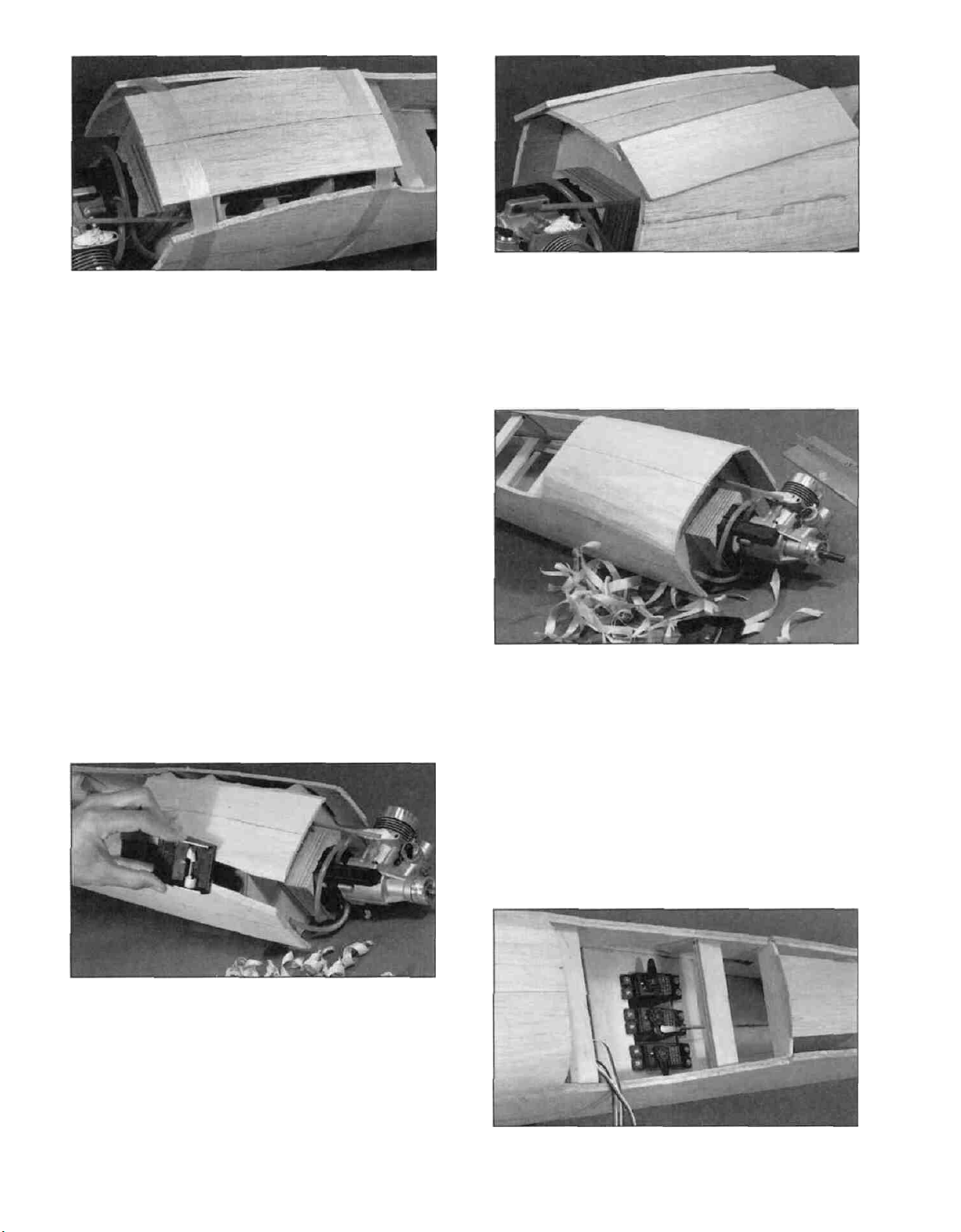
D 8. Thoroughly dampen the outside of the nose
sheeting with water and allow it to soak in for about
5 minutes or so before proceeding.
D 9. Use several strips of tape to hold the
sheeting down into place against the fuse side.
Trim the front of the nose side sheeting even with
the end of the fuse side.
D 10. Line up a metal straight edge with the top of
the fuse side (not the doubler) at both the front and
aft ends of the side sheeting. Carefully trim the
sheeting so it will sit neatly against the fuselage
doubler. Trim the aft end of the side sheeting even
with the front of F3. Gently lift the sheeting up and
apply a bead of thick CA along the side stringer,
the firewall, former F2 and the fuse doubler, and
press the sheeting down into place. Use plenty of
tape to hold the sheeting while the glue cures.
D 12. Trim and sand the front of the three nose
sheets even with the front of the fuse sides.
D 13. Install the 3/16" turtle deck stringers by
cutting them from the 3/16" sq. x 24" balsa sticks
(SKY6F26) and gluing them to formers F3, F4
and F5.
D 14. Cut a piece of 1/16" x 3/8" x 30" balsa stick
(SKY6W24) to fit between the formers F3 and F5.
Now cut this strip down the middle to form two
pieces approximately 1/16" x 3/16" x 13-1/4".
These are "shims" and are used to correctly
position the turtle deck sheeting. Sand one end of
each shim until it is approximately 1/32" thick. The
thin end will be the front of each shim.
24
Page 25

D 15. Glue these "shims" to the fuselage doubler
between formers F3 and F5 with the thin end near
F3. Refer to the F3, F4 and F5 cross sectional
views on the plans to help clarify where the shims
are positioned.
D 18. Apply a bead of CA to the stringers and the
formers and hold the sheeting in place with tape
while the glue cures. Trim the ends of the sheeting
flush with formers F3 and F5. Do this to both sides
of the turtle deck.
D 19. Sand the top of the turtle deck sheeting with
a sanding block to obtain a flat surface on which to
mount the top block.
D 16. Make the turtle deck sheeting by cutting a
1" x 7-1/2" triangle off one corner of the 1/16" x 3"
x 14-7/8" balsa sheet (SKY6F17). Flip the triangle
over and glue it to the rest of the sheet as shown in
the sketch above. Sand both sides of the sheeting
smooth.
D 17. Position the wide end of the turtle deck
sheeting against the front sheeting at former F3
and glue it to the shim with thin CA.
D 20. Glue the 3/16" x 1-1/2" x 14" balsa turtle
deck top (SKY6F16) in place.
D 21. Use a razor plane and a sanding block to
rough shape the turtle deck top to the cross
sections shown on the plans.
-25-
Page 26

D 22. For a very smooth turtle deck, pull a full sheet
of 150 or 220 grit sandpaper around a corner of your
work table. This helps "break in" the sheet. Then glue
a 1/2" sq. stick of wood to each end of the sheet.
Sand the turtle deck with long strokes while pulling
down on the sticks as shown in the photo.
can also use the full sheet of sandpaper trick to
smooth out the corners.
D 26. Securely glue the die-cut 1/8" balsa stab
base (SKY6F09) in place at the rear of the fuselage.
Sand the stab base after it is installed to remove
any bumps and give the stab a flat gluing surface.
ATTACH THE TAIL SURFACES TO
THE FUSELAGE
D 23. Use a razor plane and a coarse sanding
block to bevel the aft bottom fuse corners until they
are flush with the formers.
D 24. Shake or blow all the wood dust out of the
fuselage, and glue the 3/16" x 1-3/8" x 24" balsa
aft fuse corners (SKY6F19) to the fuselage as
shown in the photo.
D 1. Use the remaining 1/16" x 1-3/8" x 24" hard
balsa sheet to cover both sides of the tab on the
bottom front of the fin. The grain should run
longways (front-to-back) as shown in the photo.
Trim and sand the sheeting to match the shape of
the
tab.
D 25. Use a razor plane and a coarse sanding
block to rough shape the bottom fuse corners. You
D 2. Cut a notch in the turtle deck top that is as
wide as the notch in former F5 (approx. 5/16")
and 1-3/4" long. Make sure it is directly over the
former notch and pointing straight forward along
the fuse centerline.
-26-
Page 27

D 3. Test fit the fin in place. The fin post should
butt up against the fuse bottom and the fuse
doublers. Enlarge the notch if necessary to get the
fin to fit properly. When satisfied with its fit,
securely glue it in place.
D 4. Measure to the middle of the stab trailing
edge and make a line perpendicular to the TE
using a triangle.
D 6. Install the die-cut 1/8" ply stab hold downs
(SKY6F12) by gluing them to the stab and former
F5. Slant them in towards the centerline as shown
in the photo. Hold them tightly in place while the
glue cures.
D 7. Make two fin fillet tops by drawing a line 6"
from one end of a 3/16" x 1/4" x 24" balsa stick
(SKY6S04) and tapering that 6" from 1/4" thick at
the 6" mark to zero at the end. Glue these along
the base of the fin so the top edge is even with the
top of the turtle deck and continues along the
same slope.
D 5. Position the stab in place to see how it fits
against the fuse sides. Sand the stab "saddle"
and/or the stab leading edge if necessary to allow
the stab to fit flat against the balsa stab base. Use
the triangle to make sure the stab is
perpendicular to the fin. If it's not, sand the stab
base until it is. When satisfied with the fit, securely
glue the stab in place with epoxy. The line you
drew earlier should be centered between the fuse
sides and pointing directly forward. Use the
triangle to keep the stab perpendicular to the fin
while the glue cures.
D 8. Cut two scraps of 1/16" balsa sheeting
approximately 1/4" wide and 1-1/8" long. Glue one
piece to each side of the fin post near the trailing
edge. Cut two pieces of 3/16" x 1/4" stick
approximately 5-5/16" long to fit between F5 and
the fin post along the top surface of the stab. Glue
them to the stab so the outside edge of each forms
a straight line between the outside edge of F5 and
the outside surface of the 1/16" scrap piece of
sheeting. Carefully examine the photo on the
previous page to get these positioned correctly.
27-
Page 28

D 9 Cut two pieces of 1/16" balsa sheeting, from
the scrap 1/16" sheeting you used on the tail
surfaces, to fit on each side of the fin They should
be approximately 1-3/4" on the front edge, 6-1/4"
long and 1-1/4" tall at the rear Sand the front edge
so it will butt up against the turtle deck sheeting.
Glue it first to the stringer on the stab, then to the
edge of the turtle deck sheeting Try to keep it
even with the turtle deck sheeting so the fillet will
not require a lot of filler later Glue the sheeting to
the fin post and the fillet top.
D 10. Carve and sand the fillet to smooth it out
and blend it in with the turtle deck Put a strip of
masking tape along the fin to keep the sandpaper
from sanding the fin Use HobbyLite model filler if
needed to obtain a smooth looking fillet
knots, soft spots, diagonal gram and any other
imperfections If possible, position each spar so
the imperfections (if any) are on the outer half of
the wing panel (toward the tip), where they will be
least affected by high stress If the spars are
warped slightly, try to balance them out by
installing the warped spars in opposite directions
(see sketch).
NOTICE: If you feel that any of the wing parts are
unusable due to severe warps or other defects,
give us a call and we'll replace the parts
D 2 Sand one end of each 1/8 x 3/8 x 18 balsa
spar doubler (SKY6W14) to a 2" taper as shown
in the photo (8 spar doublers total).
WING
NOTE: The following instructions
explain how to build the wing on a flat
surface, directly over the plans. The jig
tabs will enable you to build a wing as
straight as your work surface. No other
special jigs are required to build your
Skybolt.
SPARS
Two warped spars installed this
way will result in a straight wing
Two warped spars Installed this
way will result in a warped wing
0 3 Glue one spar doubler to each of the eight
1/8" x 3/8" x 28" balsa spars (SKY6W12) with thick
CA Refer to the plans and align the spar and the
doublers root ends with each other Take your time
and press the spar assembly flat against the work
surface while the glue is curing Also rotate the
assembly onto its side and press it down to keep
the doubler and spar aligned and straight Do this
on a flat work surface and most warps can be
eliminated Quickly wipe off any excess glue with a
paper towel before it cures Assemble all eight
spars in this manner and sand the edges smooth.
D 1 Before using the hard balsa spars, examine
them carefully for possible imperfections. Look for
-28-
Page 29

BUILD THE BOTTOM WING
NOTE: It will be helpful to build the wing
on a piece of "Celotex"* or other semisoft (and flat) surface, into which you
may easily stick pins to firmly hold
down the wing parts while building, to
avoid warps. *Available from lumber
companies and home centers. The back
surface of some 2' x 4' ceiling tiles may
also work very well.
D D 1. Tape the BOTTOM wing plan to your flat
work surface, and cover the wing drawing with
waxed paper (so you won't glue the wing to the
plan')
D D 2 Carefully punch out all the die-cut 3/32"
and 1/8" balsa BOTTOM wing ribs (SKY6W01
and SKY6W03) Sand the edges slightly to
remove any die-cutting irregularities or 'fuzz".
D D 5 The shaped and notched wing trailing
edges (SKY6W17) are fastened together by a thin
strip of balsa Separate them by cutting with a
hobby knife Position a trailing edge (TE) in place
by working the rear end of the B3 rib into the first
3/32" wide notch in the TE Refer to the plans to
help you correctly position the TE. Center
(vertically) the TE on the B3 rib and glue it in place
with thin CA.
D D 3 Cross-pin one of the spars to the plan with
the spar down and the doubler up and near the
root The tapered end of the spar doubler should
be between the last B3 rib and the first B4 rib.
D D 6 Use the notched TE to accurately position
the outer B4 rib, and glue it to the spar and the TE.
D D 7 Install the remaining B3 and B4 ribs Glue
them to the spar and the TE with thin CA Make
sure they are fully seated on the spar.
D D 4 Glue the first B3 rib onto the spar and
place (do not glue) the outer B4 rib on the spar in
its correct position Use a 90-degree triangle to
keep the ribs vertical.
D D 8 Punch out the two die-cut 1/16" ply B5A
ribs (SKY6W13) and the four die-cut 1/8" ply B5B
29-
Page 30

ribs (SKY6W11) Carefully glue one B5B rib to each
B5A rib using thick CA Use the glue sparingly to
avoid getting glue in the l-strut cut-outs
D D 9 Carefully glue a B5B in place on the other
side of each B5A Again be careful with the CA to
avoid getting it in the l-strut cut-outs
D D 10 Glue a B5 assembly in place on the spar
with the cut-outs (slots) on top
"flashing" off the edges Be careful to cut at the
angle shown so you don't change the width of the
leading edges during this step
D D 13 Line up the 3/8 wide notch in the LE with
the B5 rib assembly and test fit the leading edge in
place Center (vertically) the LE on each rib and
glue it with CA.
NOTE: In the following steps you'll find
it necessary to remove some of the pins
holding the wing down to your building
board. As you do, take other steps as
necessary to continue holding the wing
down, such as by applying weight to the
top of the wing, or by relocating the
pins.
D D 11 Glue the top spar in place (with the
doubler down) Make sure it is fully seated in the
notches so it does not protrude above the top
surface of the ribs Remember, the spar doubler
stops just before the first B4 rib
D D 12 The shaped balsa Leading Edges
(SKY6W15) are connected by a thin strip of balsa.
Cut the two LE'S apart and carefully trim the
D D 14 Glue the pre-cut 1/16" balsa vertical grain
shear webs (SKY6W27) to the rear edge of the
spars in the first 7 rib bays (from B3 to B5) Also
glue shear webs onto the front edge of the spars
in the first 4 rib bays NOTE: You may wish to trial
fit and trim each web before gluing it in The webs
must be securely glued to the spars
D D 15 Trim off the root end of the spars and TE
slightly longer than their correct length (approx 1/64"
longer) Later, when the two wing halves are joined
together, they will be sanded to the correct length.
-30
Page 31

D D 16 Assemble a bottom wing tip by gluing a
BT1 to a BT2 (SKY6W05) as shown in the photo.
Sand both sides of the wing tip smooth.
wing tip cut-out After this glue has cured, add thick
CA to each spar in the razor saw slit to reinforce
the joint there.
D D 19 Cut the leading and trailing edges off to
match the contour of the wing tip. Do not sand or
shape them yet
D 20. Go back to step 1 and assemble the other
wing half Be sure to build a right and a left
wing panel! This is all we will do to the bottom
wing until later.
BUILD THE TOP WING
D D 1 Tape the TOP wing plan to your flat work
surface, and cover the wing drawing with waxed
paper (so you won't glue the wing to the plan')
IMPORTANT: Do not cut the left and right wing
panel drawings apart. The wing halves are joined
over the plans to achieve the correct sweep.
D D 17 Set rib B6 (SKY6W01) in place but do not
glue it yet Slide the wing tip into place through rib
B6 to check its fit When satisfied with the fit, glue
the wing tip to the leading and trailing edges and to
rib B4 Glue rib B6 in place, but do not glue it to
the spars yet. Make sure the wing tip is centered
vertically on the leading and trailing edges.
D D 18 Use a razor saw to make a cut about
halfway through each spar near the outside edge
of rib B6 This will allow the spars to bend there
without affecting the rest of the wing Cut the spars
to the correct length so they will fit down into the
wing tip cut-out Glue the spars to one another, rib
B6 and the wing tip so they are centered in the
-31
D D 2 Carefully punch out all the die-cut 3/32"
and 1/8" balsa TOP wing ribs (SKY6W01 and
SKY6W02) Sand the edges slightly to remove
any die-cutting irregularities or "fuzz".
D D 3 Cross-pin one of the spars you assembled
earlier to the plan with the spar down, and the
doubler up and near the root The tapered end of
the spar doubler should end between the last T5
rib and the first T6 rib.
D D 4 Glue the first T5 rib onto the spar and
place (do not glue) the outer T6 rib on the spar in
its correct position Use a 90-degree triangle to
keep the ribs vertical.
D D 5 Position a TE in place by working the rear
end of the T5 rib into the second 3/32" wide notch
in the TE Refer to the plans to help you correctly
position the TE Center (vertically) the TE on the
T5 rib and glue it in place with thin CA.
-
Page 32

D D 6. Use the notched TE to accurately position
the outer T6 rib and glue it to the spar and the TE.
D D 7. Install the remaining T5 and T6 ribs. Glue
them to the spar and the TE with thin CA.
D D 8. Punch out the two 1/16" ply T7A ribs
(SKY6W13) and the four 1/8" ply T7B (SKY6W11)
ribs. Carefully glue one T7B rib to each T7A rib
using thick CA just as you did earlier for the bottom
wing. Apply the glue to the T7A ribs and use the
glue sparingly to avoid getting glue in the l-strut
cut-outs.
D D 9.Carefully glue a T7B in place on the other
side of each T7A's. Again, apply the glue to the
T7A rib and be careful with the CA to avoid getting
it in the cut-outs. Apply thin CA around the edges
of the rib assembly but do not get it in the slots.
D D 11. Glue the top spar in place (with the
doubler on the bottom). Make sure it is fully seated
in the notches so it does not protrude above the
top surface of the ribs. Remember, the spar
doubler stops just before the first T6 rib.
LI LI 12. Test fit a leading edge in place. Center it
vertically on each rib and glue it with CA.
NOTE: In the following steps you'll find it
necessary to remove some of the pins holding
the wing down to your building board. As you
do, take other steps as necessary to continue
holding the wing down, such as by applying
weight to the top of the wing, or by relocating
the pins.
D D 10. Glue a T7 assembly in place with the cutouts (slots) on the bottom.
D D 13. Glue the pre-cut 1/16" balsa vertical grain
shear webs to the rear edge of the spars in the
first 6 rib bays (from T5 to T7). Also glue shear
webs on the front edge of the spars in the first 4
rib bays. NOTE: You may wish to trial fit and trim
each web before gluing it in. The webs must be
securely glued to the spars.
-32-
Page 33

D D 14. Assemble a top wing tip by gluing a TT1
to a TT2 (SKY6W05) as shown in the photo. Sand
both sides of the wing tip smooth.
D D 17 Cut the leading and trailing edges off to
match the contour of the wing tip. Do not sand or
shape them yet. Cut the root end of the LE, the TE
and the spars to the correct length.
D 18. Go back to step 1 and assemble the other
wing half. Be sure to build a right and a left
wing panel!
JOIN THE TWO TOP WING HALVES
D D 15 Remove the wing from the work surface
and set rib T8 (SKY6W01) in place but do not glue it
yet. Slide the wing tip into place through rib T8 to
check its fit. When satisfied with the fit, glue the wing
tip to the leading and trailing edges and rib T6. Make
sure the wing tip is centered on the leading and
trailing edges Glue rib T8 to the wing tip, the spars,
the leading edge and the trailing edge.
D D 16. Use a razor saw to make a cut about
halfway through each spar near the outside edge
of rib T8. This will allow the spars to bend there
without affecting the rest of the wing. Cut the spars
to the correct length so they will fit down into the
wing tip cut-out. Glue the spars to one another and
the wing tip so they are centered in the wing tip
cut-out. After this glue has cured, add thick CA to
each razor saw slit to reinforce the joint there.
D 1. Pin the top left wing panel in place over the
plans. Cut and/or sand the front edge of the trailing
edge to a taper as shown on the plans so it will accept
the 1/16" ply rear brace Do this to the right wing panel
also. Remove the wing panels from the plans.
D 2. Locate the 1/4" x 3/8" x 6-1/4" balsa center
spars (SKY6W36) Pin one of the center spars in
place over the plans. Position both wing panels so
they butt against the center spar and accurately
line up with the plans. Securely glue the center
spar to each wing panel.
-33-
Page 34

IMPORTANT - keep both wing panels
flat on the work surface during the
following steps.
D 3 Test fit the 1 /16" x 3/8" x 12-3/4" ply rear brace
(SKY6W29) in place against the trailing edges.
Sand the trailing edges if necessary to achieve a
good fit here Glue the rear brace in place so it is
centered vertically on the trailing edges.
D 6. Locate the four 1/8" x 1" x 1" ply top plate
doublers (SKY6W32) and mark the middle of one
side of each one Make the mark on a side that the
grain runs along.
D 4 Trial fit the shaped balsa center leading edge
(SKY6W16) in place between the wing panels It is
cut slightly long so trim it until it fits between the
wing panels Make sure the wing panels are lined
up with the plans to achieve the proper sweep and
glue the center leading edge in place.
D 5. Test fit the die-cut 3/32" balsa T4A ribs
(SKY6W01) in place You may cut the ribs in half
between the spar notches if needed to make them
easier to install Sand them if needed to get a good
fit, and glue them in place with CA.
D 7 Securely glue a top plate doubler to each
side of both 1/8" x 1" x 3-7/8" ply top plates
(SKY6W31) so the marks are centered in the slot
in each holder.
D 8 Drill a 5/32" hole in the edge of the
assembled plate using the slot to guide the drill bit.
Try to keep the drill perpendicular to the plate
during this step NOTE: A drill press is helpful
during this step Measure the depth of the hole
(using the drill bit) to make sure it is between 3/4"
and 7/8" deep Caution: Do not drill all the way
through the plate!
-34
Page 35

D 9 Scuff up the outside of each 5/32" brass tube
with sandpaper Clean out the inside of the tube.
Apply a small amount of 15-rninute epoxy to the
outside of the unchamfered end of the tube and
insert this end in the 5/32" hole Press the tube
completely into the hole If part of the tube is still
sticking out of the plate, just sand or cut it off with a
razor saw and chamfer it by hand
bottom of the T1 ribs Correctly position the TE of
the T1 ribs and glue them to the TE brace and the
bottom spar Slide the rear plate all the way
forward in its slot and securely glue it to the T1
ribs. Glue the ribs to the front plate
D 12. Test fit the 1/4" x 3/8" x 6-1/4" top center
spar (SKY6W36) in place Sand it if needed to
make it fit nicely and glue it in place.
D 10 Slide the 1/8" die-cut ply T1 ribs (SKY6W10)
onto both plates as shown in the photo Notice that
the brass tubes are open towards the TE of the ribs.
D 11. Place the T1/plate assembly on the bottom
center spar, and adjust it so the ribs and brass
tubes are correctly positioned with respect to the
plans Position the front plate so it is centered (up
and down) on the leading edge, and glue it to the
leading edge NOTE: When it is correctly
positioned, it will be level and there will be a 1/16"
"ledge" for the wing sheeting on the top and the
D 13. Slide the two 1/16" x 5/8" x 1-1/4" ply wire
stops (SKY6W33) in place Notice that they are
glued to the top of their slots so their bottom
surfaces are level with the top of the brass
tubes They will help guide the wires into the
tubes. Securely glue them in place
D 14 Cut a piece of inner pushrod tubing 1-1/2"
long from the remainder of the 6-1/2" long piece
supplied (PLTB004) Flip the wing over and
temporarily insert the 1/2" long piece into the front
brass tube The two front 1/4" x 3/8" x 1/2"
basswood triangle wire guides (SKY6W37) need
to be installed now They are glued to the bottom
of the wire stops so they are approximately 1/64"
away from the inner pushrod tube Be careful so
you don't glue the inner tube into the brass tube.
NOTE: Make sure the plastic pushrod tube is
straight during this step.
35
Page 36

D 15 Insert the inner tube in the rear holder (you'll
have to bend it to do so) and install the rear 1/4"
basswood triangle wire guides Make sure the
inner tube is straight during this step Remove the
inner tube.
These measurements
must be equal!
D 17. Check the alignment of the top wing by
measuring from the aft end of the fuselage to each
wing tip as shown in the sketch If you are not
satisfied with the alignment of the wing (the
measurements must be within 1/4" of being equal),
you may cut the TE of the T1 ribs loose, adjust the
wing, and re-glue the ribs.
D 16 Test fit the wing onto the cabane wires To
do so, just drop the wing down onto the wires until
the wires hit the 1/16" ply wire stops The triangles
will help line up the wires with the tubes Now slide
the wing backwards until it will go no further Look
at the cabane wires from underneath the wing to
see if they are fully inserted into the brass tubes as
shown in the photo If the wing does not easily
slide onto the cabane wires, it is usually because
the wires are not correctly aligned Follow the
guidelines outlined in the last step to adjust the
wires until the wing will slide all the way on Bend
the wires a little at a time and frequently check the
fit of the wing as you go The easiest way to
remove the wing is to wrap your fingers around the
rear cabane wires and gently push on the trailing
edge of the wing.
D 18 Sand the front corner of the center
spar/spar junction to remove the sharp corner.
Sand the front and rear surfaces of the spars to
remove any bumps.
D 19. Test fit the die-cut 1/32" ply top wing
joiners (SKY6W06) in place on the front and the
-36
Page 37

back of the spars Sand them if needed to make
them fit between ribs T1 and T4 Securely glue the
braces in place with either thick CA or epoxy.
Clamp the braces together until the glue cures.
D 20 Punch out the die-cut 1/8" ply T2A and T2B
ribs (SKY6W10) and trial fit them in place Sand
them if necessary to get them to fit nicely Do not
let the T2B's bend the trailing edge brace. Glue
these in place with CA.
D 23. Glue the 1/4" x 3/8" x 3/4" basswood screw
blocks (SKY6W39) to the outside of each T1 rib.
They should be located just behind the rear top
plate as shown on the plans and flush with the
bottom of the ribs.
INSTALL THE TOP WING
SHEETING
D 21 Trial fit the die-cut 1/8" balsa T3A and T3B
ribs (SKY6W04) in place Sand these if necessary
to achieve a good fit and glue them in place.
D 22 Install 1/16" balsa shear webs on the front
and the back of the spars between the T1 ribs and
in the bays between the T4 and T5 ribs.
D 1 Sand the outer tip of the trailing edges to fair
them in with the wing tips as shown in the photo.
D 2 Lightly sand the tops of the ribs to blend with
the notched trailing edge The 1/16" x 7/8" x 29"
balsa trailing edge sheeting (SKY6W20) is
installed now This has to be done on an absolutely
flat surface or the wing will not end up straight
Apply thick CA to one of the TE'S (except on the
tapered part past T7) and press a trailing edge
sheet in place Allow the tip end to slightly overlap
the wing tip Hold the sheeting in place until the
glue cures NOTE: The edge of the TE sheet may
not be exactly straight, but just position the sheet
so it slightly overlaps the TE, and any overlap can
be sanded off flush with the TE later.
-37-
Page 38

D 3. Now apply a drop of thin CA to each rib
(except the center ribs) where the sheeting
contacts it Do not cut the sheeting off at the center
or ends yet.
D 6 Before applying the leading edge sheeting in
the next steps, use your sanding block to lightly
sand off the edges of the shear webs and smoothly
blend the ribs to the spar Also, clean up the LE\rib
joints to remove any excess glue
D 7 Make the leading edge sheeting by cutting a
3-1/2" x 3/8" triangle off one end of each of the
four 1/16" x 2-1/4" x 29" balsa top wing LE
sheets (SKY6W21) as shown in the sketch above.
D 8. Trial fit one of the LE sheets in place on the
top of one wing panel Trim or sand the sheet if
necessary to make it fit nicely against the LE. Do
not cut it to the correct length yet.
D 4 Install the trailing edge sheeting on the
opposite wing panel Allow the two pieces to
overlap at the center for now.
D 5 Line up a metal straightedge with the center of
the wing and cut (with a sharp blade) through both
layers of trailing edge sheeting Remove the excess
and glue the two pieces together and to the ribs.
NOTE: It will be helpful to have the
following items handy for the next steps
. . . thin CA, thick (slow cure) CA, a
straight piece of wood such as an
aileron, and a wet cloth.
D 9 Hold the sheeting tightly against the LE at a
slight angle so it rests down on the ribs at the LE.
Use thin CA to glue the sheeting to the LE only.
Do not glue it to the ribs, spars or center LE yet.
-38
Page 39

D 10. Tilt the wing up, with the LE down, and
apply a drop or two of thick (slow curing) CA to
each rib. Hold the wing at an angle so the glue will
flow down and coat the edge of each rib. Apply a
line of glue to the front half of the spar (except
where the spar bends at the wing tip).
D 11. Immediately place the wing on your flat
work surface and use a piece of wood (an aileron
works OK) to hold the sheeting in place while the
glue cures. It is important to keep the wing flat
during this process as the LE sheeting will "lock"
the wing together. We won't glue the sheeting to
the wing tip until later.
D 14. Glue the LE sheeting to the center LE, the
center ribs and to each other.
D 15. Position one of the 1/16" x 2-5/8" x 13-1/2"
balsa wing center sheets as shown in the photo
and mark where it intersects the LE sheeting. Also
mark the front center of the sheet.
D 12. Install the opposite wing panel top sheeting
following the same procedure. Allow the center
end of the sheeting to overlap the LE sheeting
already installed.
D 13. Trim the LE sheeting using a metal
straightedge just as you did with the TE sheeting.
D 16. Cut the center sheet on the marks you just
made. Save the two triangles.
D 17. Glue the wing center sheet in place against
the LE sheeting. Make sure the wing is flat during
this step.
-39-
Page 40

D 18. Glue the two triangles you cut off the center
sheet to the trailing edge sheeting as shown in the
photo. After the glue cures, use a metal straight
edge as a guide to trim the front edge of the
triangles straight and even with each other.
D 19. Cut a strip of balsa center sheeting to fit in
the gap and glue it in place.
D 22. Add two 1/16" x 7/8" x 28" balsa TE sheets
just as you did earlier on the top surface. Do one
panel at a time and be careful to keep from
warping the wing during these steps. HINT: Do not
get glue in the I-strut slot when gluing the
sheeting to rib T7. An aileron placed under the TE
will keep it straight while the glue is curing.
D 23. Install the remaining two 1/16" x 2-1/4" x
28" top wing LE sheets, using the same
procedure outlined in steps 8 - 14. Be very careful
when applying glue to the T7 ribs to avoid getting
glue in the l-strut slots. Mark on the LE and the TE
sheeting where the cabane wires will attach.
D 20. Cut a small triangle from scrap 1/16"
sheeting to fit behind the trailing edge sheeting at
the center. Glue it in place.
D 21. Flip the wing over and carefully trim off the
jig tabs on the bottom of the wing. A razor saw
works well for this. Use a sanding block with fine
grit sandpaper to touch up where the tabs were
and to blend the ribs into the TE. Be careful not to
change the shape of the ribs.
D 24. Install the bottom center sheeting just as
you did on the top surface. Refer to steps 15
through 20 for instructions.
D 25. Cut a semi-circle or similar shape out of the
sheeting between ribs T4 and T5 as shown in the
photo. Do this on both the top and the bottom of
the wing.
-40
Page 41

D 26. Cut a rectangle out for each cabane wire.
Start the rectangle out small and gradually enlarge
it to allow the wires to easily slip into place. When
the rectangles are correctly sized so the wing will
easily slip on and off without hitting the wood, soak
the area around the rectangle with thin CA to
reinforce the wood. A small strip of very light
fiberglass cloth (3/4 oz. or so) can also be used to
reinforce this area.
D 27. Wet the LE and the TE sheeting at each
wing tip. Allow it to soak in for about 5 minutes.
Then press the sheeting up against the wing tip
and glue it in place with CA. Do the top and bottom
sheeting at the same time to keep from bending
the tip.
D 29. Use a straightedge to draw lines on the LE
sheeting along the edges of the T7 rib assemblies
as shown in the photo.
D 30. Carefully cut through the LE sheeting to
expose the front I-strut slot. Take your time and
cut a little at a time to end up with a neat looking
slot similar to the one in the photo. Notice that the
edges of the slot are tapered outward to make it
easier to install the I-struts later.
D 28. Use a 1/16" x 2-5/8" x 13-1/2" piece of balsa
wing center sheeting to finish sheeting the wing
tips. Cut a piece about 2-3/4" long (to fit over rib
T8) and glue it up against the LE sheeting. Then fill
in the gap with some scrap 1/16" balsa. Trim the
ends to the shape of the wing tip and sand the tip
smooth. Do this to the top and the bottom of both
wing tips.
-41
D 31. Cut through the TE sheeting to expose the
rest of the rear l-strut slot. The front portion of the
rear slot will be cut out later after the cap strips
have been installed. Pick or blow all the balsa
scraps out of the slots when you are done.
-
Page 42

FINISH THE TOP WING
D 32. Sand the entire trailing edge of the wing to
remove any overlapping sheeting. Measure and
mark the center of the front edge of the 6-1/4" long
balsa center trailing edge (SKY6W19) and make
a mark there. Center this part on the ply trailing
edge brace and glue it in place with thick CA.
Make sure it is straight and perfectly aligned with
the chord line of the airfoil (see sketch below).
edge and mark where to cut it to fit next to the
center trailing edge. NOTE: We are referring to this
piece as an aileron even though it won't actually be
an aileron.
D 2. Cut the aileron off at this mark and test fit it in
place. Sand the root end if necessary to achieve a
good fit and glue it to the TE and the center TE.
Make sure it is lined up perfectly with the chord line
of the airfoil as you did earlier for the center TE.
IF YOU ARE INSTALLING
AILERONS ON THE TOP WING
SKIP TO STEP 4
D 1. Hold a 17/32" x 2" x 28" tapered balsa
aileron (SKY6W18) in place against the trailing
D 3. Cut the tip end of the aileron off following
the contour of the wing tip, and sand the entire
wing tip smooth. Skip ahead to "Build the
Interplane Struts."
D 4. Position a 17/32" x 2" x 28" tapered balsa
aileron (SKY6W18) on the top wing plan and line it
up with the trailing edge on the left wing panel. Use
the cutting marks drawn on the plans to make the
three required cuts. You will now have an inner
TE, an aileron and an outer TE.
D 5. Draw a centerline along the aft edge of both
trailing edges and the leading edges of both
ailerons. This will help keep the hinges centered later.
42
Page 43

D 6 Trial fit the inner TE in place against the
center TE Sand it if necessary to achieve a good
fit and glue it in place Make sure it is aligned with
the center TE and the chord line of the airfoil.
D 7 Securely tape the aileron in place
approximately 1/16" away from the inner TE Make
sure it is aligned with the inner TE and the chord
line of the airfoil
D 9 Cut and sand the tip of the wing to match the
outline on the plans Sand the entire wing tip smooth.
D 10 Remove the aileron and bevel the front edge
to a "V" shape as shown on the cross section view
of the plans A razor plane and a coarse sanding
block make this step quick and easy.
D 11 Place the aileron over the aileron drawn on
the top (left) wing plan and mark the hinge
locations Hold the aileron in place on the wing and
transfer the marks over to the wing Cut the hinge
slots following the hinge slotting guidelines on
page 10
D 8 Glue the outer TE in place approximately
1/16" away from the aileron Look down the trailing
edge of all three pieces to make sure they are all
aligned with each other.
D 12 Cut the top wing center TE template out of
the plans and tape it in place on the wing Mark
where the center trailing edge should be cut and
remove the paper
-43-
Page 44

D 13. Cut and sand the center trailing edge to
achieve a nice, smooth semi-circle. Also round off
the edge as shown in the photo.
D 14. Make a mark on the LE and TE sheeting at
each of the ribs. This will make it easier to install the
cap strips. Cut the cap strips from the 1/16" x 3/8" x
30" balsa sticks (SKY6W25) and glue them in place
on the top and bottom of each rib. When installing
the cap strips on the T7 ribs, be careful to keep
from getting glue in the l-strut slots.
balsa sheets (SKY6W25) as shown in the photo.
Notice that a triangle is cut out of the sheeting to
cover one tip of each strut.
D 2. Trim the sheeting flush with the edges of the Istruts except where the wires will go. Leave about
1/8" extra at these points as shown in the photo.
D 15. Cut through the cap strips on the bottom of
rib T7 to expose the rest of the l-strut slot. Harden
the area around the slot with thin CA or lightweight
fiberglass cloth.
BUILD THE INTERPLANE STRUTS
D 1. Punch out the two die-cut 1/8" ply l-struts
(SKY6W08) and sand off any rough edges. Glue
the l-struts to one of the 1/16" x 3 x 24" hard
D 3. Use a small file, a grinding wheel or a Dremel
Moto-Tool with a cut-off wheel to smoothly chamfer
the longer ends of all the 1/16" wires (WBNT181
and WBNT182). These ends will slide into the wing
rib assemblies so they need to be smooth. The
photo above shows which ends to chamfer and
what they should look like when they are done. It is
important that you do a good job here so the l-strut
interlocking system will work well.
D 4. Position the l-struts over the l-strut detail
drawing on the plan. Scuff the short end of each
1/16" wire with fine sandpaper and tack glue them
into the l-struts with a drop of thin CA. There are
only two different types of 1/16" wires,
-44
Page 45

and one of each goes into each end of the I-struts.
The wires should be positioned in the strut so the
top parts of the top wires and the bottom parts of
the bottom wires line up with the plan This will set
the correct -1 degree of incidence between the top
and bottom wings The photo shows how the wires
should be installed IMPORTANT Make sure both
of the l-struts are exactly the same height and
have the same incidence angle
D 7 Fill the horizontal wire slots with thick CA by
holding the l-struts up and allowing the CA to flow
into each slot The 1/16" wires should be glued in
place as securely as possible Apply some
lightweight (3/4 oz) fiberglass cloth on both sides
and both ends of each l-strut as shown in the photo.
D 8 Mark one strut "Left" and the other one
"Right" Also mark the top and bottom of each one.
Refer to the plans to determine the top and bottom.
D 5 Glue the 1/32" locking wires (WBNT183) in
place behind the rear wires as shown in the photo
and on the plans These locking wires should only
be glued along the inner 1" because they have to
bend out to unlock the l-struts Add thick CA to all
the wires to securely glue everything in place Do
not allow the glue to drip down and glue the 1/32"
wires to the 1/16" wires below the balsa sheeting.
D 6 Sand the exposed plywood smooth to
remove any glue bumps, and install the remaining
1/16" hard balsa sheeting Sand the sheeting flush
with the edges of the plywood Then round off the
edges to achieve a smooth, aerodynamic cross
section on the entire strut.
D 9 Sight down the wires on each end of the Istruts to make sure the horizontal parts of both
wires are perfectly aligned with each other If they
are not, gently bend them until they are Test fit the
l-struts into the slots in both the top and bottom
wings The left strut should be fitted into the left
wing panels and the right one into the right wing
panels. The wires can be bent slightly if needed to
get the smooth sliding action desired Make sure
the struts will slide far enough forward to allow the
locking wires to snap down into place With the
locking wires snapped into position, mark on each
locking wire where the surface of the wing is.
-45-
Page 46

D 10. Remove the l-strut and bend the locking wire
backwards about 45 degrees just above the marks
you made. Do this to both ends of both struts.
D 11. Final sand the struts to prepare them for
finishing. You can cover the struts with MonoKote
or you can paint them. If you decide to paint them,
first fill the wood grain with polyester finishing resin
or something similar to obtain a smooth looking
paint job.
Check the fit of the two panels. The spars, leading
and trailing edges should all meet up nicely. If they
don't, sand where needed and re-check the fit.
When satisfied with the fit, glue the two panels
together with thick CA or epoxy. Make sure the
spars and leading and trailing edges line up with
each other, and the wing is up against former F2.
D 3. After the glue is completely cured, carefully
remove the bottom wing from the l-struts and place
it on your work surface with the leading edge down.
JOIN AND SHEET THE BOTTOM
WING
D 1. Flip the fuselage upside down and install the
top wing. Insert the l-struts into their respective
slots in the top wing.
D 4. Trial fit the die-cut 1/16" ply aft dihedral
brace (SKY6W07) in place. You may have to sand
the ends to get it to fit in if you sanded much on the
ends of the spars. Securely glue the brace to the
back of the spars.
D 2. Insert the l-struts into the bottom wing panels
and let the panels rest on the fuselage wing saddle.
D 5. Install the die-cut 1/8" balsa B2A and B2B
ribs (SKY6W04) as shown on the plans and in
the photo.
-46-
Page 47

D 6. Trial fit the die-cut 1/16" ply front dihedral
brace (SKY6W07) in place. Sand the ends of the
brace if necessary to get it to fit between the B2A
ribs. Securely glue the brace to the front of the spars.
D 7. Cut 1/16" balsa shear webs to fit between the
B2 and B3 ribs, and securely glue them to the
front of the spars.
D 9. Glue the die-cut 1/8" ply B1B ribs
(SKY6W10) in place.
D 10. Trial fit the die-cut 1/16" ply leading and
trailing edge braces (SKY6W07) in place between
the B1A and B1B ribs. The LE brace should be
centered on the LE to allow for the 1/16" LE sheeting
which will be applied later. Sand them if necessary to
get them to fit in, and glue them in place.
D 8. Test fit the 1/4" x 1" x 2" ply front wing bolt
plate (SKY6W30) into the slots of the die-cut 1/8"
ply B1A ribs (SKY6W10). Enlarge the slots if
necessary for the bolt plate to fit. Position the ribs
in place with the bolt plate still in the slots. Make
sure the ribs are correctly lined up with the LE and
spars, and securely glue them in place. Securely
glue the wing bolt plate to the ribs.
D 11. Sand the outer tip of the trailing edges to fair
them in with the wing tip as you did on the top
wing earlier.
D 12. Lightly sand the tops of the ribs to blend
with the notched trailing edge. Now install the 1/16"
-47-
Page 48

x 7/8" x 28" balsa trailing edge sheeting
(SKY6W20). This must be done on an absolutely
flat surface or the wing will not end up straight.
Apply thick CA to one of the TE'S (except on the
tapered part past B6), and press a trailing edge
sheet in place. Line up the root end of the sheeting
with the center joint of the trailing edges Hold the
sheeting in place until the glue cures NOTE: The
edge of the TE sheet may not be exactly straight,
but just position the sheet so it slightly overlaps
past the TE, and any overlap can be sanded off
flush with the TE later.
NOTE; It will be helpful to have the
following items handy for the next steps
. . . thin CA, thick (slow cure) CA, a
straight piece of wood such as an
aileron, and a wet cloth.
D 17 Hold the LE sheeting tightly against the LE
at a slight angle so it rests on the LE of the ribs.
The root end of the sheeting should be lined up
with the LE joint at the wing centerline. Use thin
CA to glue the sheeting to the LE only. Do not glue
it to the ribs or spars yet.
D 13. Now apply a drop of thin CA to each rib
where the TE sheeting contacts it. Be careful not to
get any glue in the B5 rib slots.
D 14. Install the trailing edge sheeting on the
opposite wing panel Butt the root end of this side
against the TE sheeting already installed.
D 15. Before applying the leading edge sheeting
in the next steps, use your T-bar to lightly sand off
the edges of the shear webs, and smoothly blend
the ribs to the spar. Also, clean up the LE/rib joints
to remove any excess glue.
D 18. Tilt the wing up, with the LE down, and
apply a drop or two of thick (slow curing) CA to
each rib Hold the wing at an angle so the glue will
flow down and coat the edge of each rib Apply a
line of glue to the front half of the spar (except
where the spar bends at the wing tip) Be very
careful not to get glue in the I-strut slots!
D 16. Trial fit one of the 1/16" x 2-1/8" x 28" balsa
bottom wing LE sheets (SKY6W22) in place on the
top of one wing panel Trim or sand the front edge of
the sheet if necessary to make it fit nicely against the
LE. Do not cut it to the correct length yet.
D 19. Immediately place the wing on your flat
work surface, and use a piece of wood (an aileron
-48-
Page 49

works OK) to hold the sheeting in place while the
glue cures. It is important to keep the wing flat
during this process as the LE sheeting will help
"lock" the wing together. We won't glue the
sheeting to the wing tip until later.
D 20. Install the opposite wing panel top sheeting
following the same procedure. Cut and sand the
root end of the sheeting to fit nicely against the LE
sheeting already installed.
D 23. Flip the wing over, and carefully trim off the
jig tabs on the bottom of the wing. A razor saw
works well for this. Use a sanding block with fine
grit sandpaper to touch up where the tabs were,
and to blend the ribs into the TE. Be careful not to
change the shape of the ribs during this step.
D 24. Add the two remaining 1/16" x 7/8" x 28"
balsa TE sheets just as you did earlier on the top
surface. Do one panel at a time, and be careful to
keep from warping the wing during these steps.
HINT: An aileron placed under the TE will keep it
straight while the glue is curing.
D 21. Position one of the 1/16" x 2-5/8" x 13-1/2"
wing center sheets as shown in the photo, and
glue it in place (against the LE sheeting). Allow the
sheeting to gently bend between the B1 ribs.
0 25. Install the two remaining 1/16" x 2-1/8" x 28"
bottom wing LE sheets, using the same procedure
outlined in steps 15-20. Be sure to keep the wing
absolutely flat during this step to avoid warps.
FINISH THE BOTTOM WING
IF YOU ARE USING ONLY ONE
AILERON SERVO SKIP TO STEP 2
D 22. Lay a 1/16" x 2-5/8" x 13-1/2" piece of balsa
center sheeting in place over the gap. Mark where
to cut it, trim it to fit, and glue it in place.
D 1. The aileron servo extension cables need to
be installed now. Approximately 24" of extensions
are required for each aileron. We used one
49-
Page 50

400mm (16") and one standard Futaba extension.
The extensions are glued into the wing, so when
using two extensions per servo it is a good idea to
tack glue or heat shrink the connectors together.
Glue the servo end connector to the last B4 rib,
and glue the extension to each rib as shown in the
photo. Cut a hole in the top center sheeting, and
route the servo extensions through the hole.
D 2. Install the bottom center sheeting just as you
did on the top surface. Refer to steps 21 and 22
for instructions.
D 5. Use a 1/16" x 2-5/8" x 13-1/2" piece of balsa
wing center sheeting to finish sheeting the wing
tips. Cut a piece about 2-3/4" long (to fit over rib
B6), and glue it against the LE sheeting. Then fill in
the gap with scrap 1/16" balsa. Trim the ends to
the shape of the wing tip, and sand the tip smooth.
Do this to the top and the bottom of both wing tips
just as you did on the top wing.
D 3. Cut a semi-circle, or similar shape, out of the
sheeting between ribs B2 and B3 as shown in the
photo above.
D 4. Wet the LE and the TE sheeting at each wing
tip. Allow it to soak in for about 5 minutes. Then
press the sheeting against the wing tip, and glue it
in place with thin CA. Do the top and bottom
sheeting at the same time, just as you did for the
top wing.
D 6. Use a straightedge to draw lines on the LE
sheeting along the edges of the B5 rib assemblies.
D 7. Carefully cut through the LE sheeting to
expose the front l-strut slot. Take your time and
cut a little at a time to end up with a neat looking
slot similar to the one in the photo. Notice that the
edges of the slot are tapered outward to make it
easier to install the l-struts later.
50
Page 51

D 8. Cut through the TE sheeting to expose the
rest of the rear I-strut slot. The front portion of the
rear slot will be cut out later after the cap strips are
installed. Pick or blow all the balsa scraps out of
the slots when you are done.
D 9. Sand the entire trailing edge of the wing to
remove any overlapping sheeting. Skip ahead to
the section entitled ONE AILERON SERVO if you
are using only one aileron servo (on page 53).
D 11. Tape the hatch cover in position,
approximately 1/32" away from the TE sheeting,
and add 1/16" balsa between the front of the hatch
and the LE sheeting. Allow a 1/32" gap between
the front of the hatch and the balsa sheet. Drill four
1/16" diameter holes through the hatch and the
rails, at each punch mark.
D 12. Remove the hatch, and enlarge the holes in
the hatch only to 3/32". Then countersink each
hole so the #2 flat head screws (SCRW069) will
be flush with the bottom surface of the hatch.
D 10. Cut the aileron hatch rails from the 3/16" x
3/8" x 12" basswood stick (SKY6W28) to fit
between the last B3 rib and the first B4 rib. Use a
die-cut 1/16" ply hatch (SKY6W36) to help you
space them. Glue the basswood rails to the ribs,
flush with the top edge of the ribs. The TE sheeting
should overlap the aft rail slightly. NOTE: When the
rails are properly installed, the 1/16" ply hatch will
be flush with the bottom surface of the wing.
D 13. Cut two 3-1/4" long pieces of balsa from the
1/8" x 1/4" x 15" balsa stick (SKY6W26) to fit next
to the ribs bordering the hatch. These will help
strengthen these ribs. Glue these in place so they
will not interfere with the cap strips on these ribs.
Refer to the plans to help you position these pieces.
-51
Page 52

D 14. Install the hatch cover with four #2 flat head
screws. Flip the wing over, and set your aileron
servo on the hatch cover. Normally, the servo
needs to be as far forward as possible so it will not
protrude above the top surface of the wing. You
may cut the front hatch rail if needed to move the
servo up against the shear webs.
D 17. Position a 17/32" shaped balsa aileron
(SKY6W18) on the BOTTOM wing plan, and line it
up with the trailing edge on the left wing panel.
Use the cutting marks drawn on the plans to
make the three required cuts. You will now have an
inner TE, an aileron and an outer TE.
D 18. Draw a centerline along the aft edge of the
trailing edge. This will help keep the hinges
centered later.
D 15. Mount the servo to the hatch using the 1/4"
x 3/8" x 3/4" basswood servo mounts (SKY6W39)
provided. Securely glue the mounts to the hatch.
Then screw the servo to the mounts using the
screws that came with the servos. Cut three arms
off of a large 4-arm servo horn, and test fit the horn
on the servo.
D 16. Test fit the hatch in place with the servo
attached. Make sure you have enough room to
place the excess cable where it won't interfere with
the servo operation. NOTE: You may have to
move the servo extension connector if the servo
will get in its way. Tack glue the extension and
connector to the ribs.
D 19. Trial fit the inner TE in place against the TE.
Sand it if necessary to achieve a good fit, and glue
it in place. Make sure it is aligned with the chord
line of the airfoil.
D 20. Securely tape the aileron in place
approximately 1/16" away from the inner TE. Make
sure it is aligned with the inner TE and the chord
line of the airfoil.
-52
Page 53

ONE AILERON SERVO
D 21 Glue the outer TE in place approximately
1/16" away from the aileron Look down the trailing
edge of all three pieces to make sure they are all
aligned with each other.
D 22 Cut and sand the tip of the wing to match
the outline on the plans Sand the entire wing tip
smooth.
D 1 Cut a notch in each grooved balsa bottom
wing center TE (SKY6W40) The notch should be
3/4" from one end, and only needs to be in the top
side of the groove Make a right and a left piece as
shown in the photo.
D 2 Roughen the short end of the aileron torque
rods with 100-grit sandpaper, and file the same
end to a wedge shape as shown in the sketch
above Also roughen the outer surface of the
plastic bearing tubes.
D 23 Remove the aileron, and bevel the front
edge to a "V" shape as shown in the cross section
view on the plans
D 24 Place the aileron over the aileron drawing
on the bottom wing plan, and mark where the
hinges should go Hold the aileron in place on the
wing, and transfer the marks over to the wing Cut
the hinge slots following the hinge slotting
guidelines on page 10 Skip the next section
(One Aileron Servo) if you are installing two
aileron servos.
D 3 Trial fit the torque rods into the center TE
pieces, and hold or tape them against the wing TE.
Mark on the wing TE where to cut notches to allow
the torque rods to rotate forward The threaded
portion of the torque rods should be on the top
surface of the wing! Sand the two TE pieces so
they will join properly at the center of the wing
D 4 Clean the torque rods and bearing tubes with
alcohol Slide the plastic bearing tubes toward the
threaded end of the torque rods Then use a
toothpick to apply Vaseline to both ends of the
bearing to keep glue from getting inside the bearing.
-53-
Page 54

D 5. Glue the torque rods into the grooves in the
center TE pieces. Make sure you install the left
torque rod in the left TE piece.
D 6. Glue the center TE'S to the wing. It is very
important that they are aligned correctly with the
chord line of the airfoil. Do not allow them to tilt up
or down, and make sure the threaded part of the
torque rods are on the top of the wing.
D 9. Drill a 7/64" hole in the ailerons at the torque
rod locations, starting at the LE centerline and
drilling straight in approximately 1-1/8". The hole is
drilled slightly oversize to allow for positioning, and
to create a hard epoxy "sleeve" around the wire.
D 10. Use a sharpened 1/8" diameter brass tube
to cut a groove in the leading edge of the ailerons
to accept the torque rods.
D 11. Lay the ailerons on the plan, and mark the
hinge locations on each aileron. Trial fit the
ailerons in place on the torque rods, and transfer
the hinge marks over the wing TE.
D 12. Cut the hinge slots in the ailerons and the
wing TE following the hinge slotting guidelines on
page 10.
D 7. Cut the ailerons from the 17/32" shaped
balsa aileron stock. They should be 21" long. Draw
a center line down each aileron, and bevel the
front edge to a "V" shape as shown on the plans.
D 8. Hold the ailerons in place approximately
1/16" away from the center TE pieces with the
torque rods resting on top of the ailerons. Mark the
torque rod locations on the top of the ailerons.
D 13. Insert the hinges into the slots, and trial fit the
ailerons in place on the wing. Do not glue the hinges
in place until after the wing is covered. Tape the
ailerons to the center TE pieces to keep them aligned.
D 14. Glue on the remaining pieces of aileron stock
at each tip. They should be positioned approximately
-54-
Page 55

1/16" away from the ailerons, and line up with the
ailerons and the chord line of the airfoil
D 15 Cut off the excess tip stock following the
contour of the wing tip, and sand the entire wing
tip smooth
Nylon Swivel
Nylon Swivel
Clevis
D 18 Thread the nylon swivels (NYLON20) onto
the torque rods until the pins are approx 3/4"
above the surface of the wing Screw a 12"
threaded pushrod wire (WIRES16) all the way
onto each nylon swivel clevis Back the threaded
wire out of each clevis approximately 4 turns and
snap them onto the nylon swivels.
D 16 Test fit your servo in the die-cut 1/8" ply
aileron servo tray (SKY6W10) Enlarge the tray
opening if needed to fit the servo Glue the tray in
position on the bottom wing The front edge of the
tray should be even with the back edge of the LE
sheeting Cut the balsa center sheeting out of the
inside of the servo tray opening.
D 19 Cut two opposing arms off a large 4-arm
servo horn, and drill out the outer holes to 5/64".
Install the horn on the servo Rotate the horn to its
neutral position, and lay the pushrod wires on top
of the horn Mark on the wires where they cross
the outer holes in the servo horn.
D 17 Insert the servo into the servo tray If the
servo hits the bottom sheeting before the mounting
lugs touch the tray, glue the 1/8" x 3/8" x 2"
basswood servo risers (SKY6W41) in place.
When satisfied with the fit of the servo, mount it
using the screws provided with your radio.
D 20 Make a Z-bend at each of the marks you
just made, and test fit the wires into the servo horn.
You may have to bend the pushrod wires slightly to
allow the wires to rotate smoothly.
-55-
Page 56

FINISH AND ATTACH THE WING
D 1. Make a mark on the LE and TE sheeting
where each of the ribs are. This will make it easier
to install the cap strips. Cut the cap strips from the
1/16" x 3/8" x 30" balsa sticks (SKY6W24), and
glue them in place on the top and bottom of each
rib. When installing the cap strips on the B5
ribs, be careful to avoid getting glue in the Istrut slots.
D 4. Sand the wing saddle smooth, and test fit the
bottom wing in place. You may have to sand the
wing saddle or the wing TE slightly to get a good fit
between the two. It is very important that the wing
sits nicely in the saddle. Do not sand the saddle so
much that it changes the incidence of the wing.
D 2. Cut through the cap strips on the top of rib B5
to expose the rest of the l-strut slot. Harden the
area around the slot with thin CA or lightweight
fiberglass cloth.
D 5. Position the wing on the fuse, and check to
see if it's level with the stab. If it's not, adjust the
wing saddle until it is. Also make sure it is straight
in relation to the fuse. Use a string attached to the
middle of the fin TE to measure to the wing tips as
you did earlier for the top wing.
D 3. Flip the wing over, and glue the die-cut 1/16"
ply rear wing bolt plate (SKY6W07) to the bottom
of the wing with the punch mark showing.
D 6. When the wing is correctly aligned, securely
hold or tape it in place. Drill a 1/4" hole 1-3/8" back
from the front of the LE, down through the wing
and through the wing bolt block in the fuse.
Without moving the wing, drill another 1/4" hole
at the punch mark on the rear wing bolt plate.
When drilling these holes, keep the drill
perpendicular to the wing bolt plates.
-56-
Page 57

D 7 Remove the wing, and enlarge the holes in
the fuselage wing bolt blocks only to 19/64"
(5/16" will work) Flatten out or cut off the teeth"
on the two 1/4 blind nuts, and insert them into the
bolt blocks They should be inserted from the top
of the block and glued in place with thick CA or
epoxy Be careful not to get glue on the threads
D 2 Tack glue the die-cut 3/32" balsa rear belly
former (SKY642) in place against former F3 and
the wing TE Sand it until it matches the contour of
the fuse bottom.
D 3 Carefully remove the belly formers, and draw
an arc 3/32" inside the curved edge of both
formers Cut and sand the former down to the new
arc This will allow for the 3/32 belly sheeting to be
installed flush with the fuse bottom
D 8 Enlarge the front wing bolt hole in the wing
bottom sheeting to 1/2" diameter so the head of
the bolt will fit through Test fit the wing in place
with the two 1/4-20 nylon bolts (NYLON13)
NOTE You may cut approximately 3/4" off of each
bolt to make them easier to install.
FINAL ASSEMBLY
BUILD THE BOTTOM WING
FAIRING
D 1 Final sand the bottom nose of the fuselage to
obtain the smooth shape shown on the fuselage
cross sectional views Install the wing on the fuse,
and tack glue the die-cut 3/32 balsa front belly
former (SKY6W42) in place against former F2 and
the wing LE Sand it until it matches the contour of
the nose bottom
D 4 Glue the front belly former to the wing LE
approximately 1/32" behind F2 Do not glue the
belly formers or the wing to the fuselage!
D 5 Glue the rear belly former to the wing TE
approximately 1/32" in front of F3 Do not glue
the belly formers or the wing to the fuselage!
-57-
Page 58

D 6. Cut a piece of 3/16" sq. balsa stick
(SKY6F26) to fit between the two belly formers,
and glue it to the formers and the wing where the
wing touches it. You will have to cut a notch in the
stick to clear the rear wing bolt.
D 7. Smoothly sand the 3/16" stick down until it is
only 1/16" thick at the low point of the wing
(around the spar). The stick should smoothly taper
from 3/16" to 1/16" and back to 3/16" to smoothly
continue the bottom curve of the fuselage.
NOTE: The sheeting should only lap
onto the 3/16" stick halfway (3/32") to
allow room for the other side to glue on.
Try to center the die-cut semi-circles
over the wing bolts
D 10. Glue the other side of sheeting in place. Fill
any gaps with HobbyLite model filler, and sand the
belly fairing to smoothly blend in with the fuselage
and wing.
D 8. Sand the outside curved edges of the die-cut
3/32" balsa belly sheeting to "feather" the edge so it
will lay down on the wing better. Do this to both pieces
but make sure to make a right and a left piece!
D 9. Glue one piece of belly sheeting to the 3/16"
stick and the front and rear belly formers.
D 11. Cut through the 3/16" stick to get the wing
bolts out. Smooth out the edges of the wing bolt
holes, and harden the area around the wing bolt
holes with thin CA or lightweight fiberglass cloth.
INSTALL THE LANDING GEAR
D 1. Measure forward 2-7/8" from the back of F2,
and draw a line. Use a razor saw to cut through the
3/16" balsa sheeting and the balsa fuse corners
until the saw hits the landing gear plate.
-58-
Page 59

D 2. Now measure 2-1/8" to each side of the
center of the fuse bottom, and make a mark on the
saw cut you just made. Measure 1-7/8" to each
side of the center at F2, and make a mark on the
rear edge of the sheeting. Connect the marks on
each side with straight lines. Then cut along these
lines with a hobby knife. Remove the bottom piece
by pulling it loose from F2. Save this piece, as it
will be glued back on later.
D 3. Measure and mark the centerline of the
aluminum landing gear (L4-U). Draw a line 1" on
both sides of the line you just drew. Now draw lines
1/2" from the front and back edges of the gear.
The photo above will help clarify this. Drill 5/32"
holes where shown on the photo above.
#6 x 3/4" Sheet Metal Screw
D 5. Securely mount the gear with the three #6 x
3/4" sheet metal screws (SCRW018) provided.
Put a drop of thin CA on each screw to keep them
from coming loose.
D 6. Trim the bottom piece you cut out earlier to fit
back in, and glue it in place. Sand the bottom of
the fuse smooth again, and fill in any gaps with
HobbyLite model filler.
D 4. Test fit the landing gear on the 1/4" ply
landing gear plate so it is centered on the plate
and the straight edge of the gear legs is facing
forward. Sand the balsa wood corners if needed to
permit the gear to sit flat on the ply plate. Mark on
the ply plate where to drill the mounting holes.
Remove the gear, and drill 3/32" holes through the
landing gear plate.
ASSEMBLE THE COWL
D 1. Trim the ABS cowl front (COWL009) and the
ABS cowl back (COWL010) out of their bases by
cutting 3/16" below the molded-in scribe lines with
a hobby knife. Sand the cut edges smooth.
59-
Page 60

D 2 Cut the center out of the cowl back Leave a
1/8" "lip" around the inside of the cowl back to give
it some extra strength Sand the inside edge of the
lip smooth You can make this cut with a hobby knife
if you start out with a shallow cut and just go a little
deeper on each pass, but a Dremel Moto-Tool with
a conical pointed bit works much easier.
on the cowl back. Using medium grit sandpaper,
lightly scuff up the surfaces where the two pieces
will be joined for better glue adhesion Make sure
they are correctly aligned with each other (look at
the cowl profile from the side and top) and glue
them together with CA.
D 5 Lightly scuff the area around the joint line
with fine grit sandpaper Use HobbyLite model filler
to fill the joint line After the filler dries, sand the
entire cowl smooth.
D 3 Cut out the center of the cowl front, leaving
about a 1/2" lip around the edge Also cut out the
air inlets When cutting the air inlets, cut only the
depressed surface away and leave the curved
sides of the inlets on the cowl. They look better
and add strength
D 6. Measure from the front of the firewall to the
face of the thrust washer, and write this
measurement down here
the measurement reads 6-1/32".
D 7 Remove the engine, and final sand the nose of
the plane smooth The front 3/4" of the nose should
be tapered in slightly to help the cowl slide on.
_____".
In the
photo
D 4 Test fit the cowl front onto the cowl back.
Sand the cowl front if necessary until it fits tightly
D 8 Test fit the cowl on the nose You may
have to sand the nose more to get the cowl to fit
far enough onto the plane Measure from the
firewall to the front of the cowl This measurement
should be approximately 1/16" less than the
measurement you wrote down above.
-60-
Page 61

NOTE: If you are going to use a spinner
that has a backplate that extends
behind the face of the thrust washer,
you will need to allow for the additional
space required.
D 9. When satisfied with the fit of the cowl, remount the engine Remove the needle valve and
muffler, and stuff pieces of paper towels into the
openings to keep dust out of the engine.
D 10 The cowl must now be cut out to clear the
engine head and muffler You also need to drill holes
for the needle valve, idle adjustment and choke (if
it's a 4-cycle) This is purely a "cut a little and test fit
it" type of operation that requires patience It may
seem like an impossible task, but take your time and
cut only a little at a time and you will end up with a
nice looking cowl A Dremel Moto-Tool with a
conical pointed bit works well for this.
of the cowl, approximately 3/8" in front of the cowl
aft edge The holes should be somewhat centered
on the sides and go through the balsa fuselage
D 13. Remove the cowl, and locate the four 1/8" x
3/4" x 3/4" ply screw plates (SKY6F29) Center a
screw plate over each 1/16" hole on the inside of
the fuselage, and glue them in place.
D 11 Once you get the cowl to fit over the engine,
place the spinner backplate on the engine The
cowl is correctly positioned when the spinner
backplate is centered in front of the cowl and there
is approximately 1/16" between the backplate and
the cowl.
D 14. Using the holes already in the fuselage as
guides, drill 1/16" holes through the four 1/8"
ply plates.
D 15. Enlarge the holes in the cowl only to 3/32",
and glue a #2 washer (WSHR001) at each hole
with CA (See photo at step 16).
NOTE: This step is purely a "cutand-fit"
kit; therefore, we can only tell you
what worked for us. Even if you use
the same engine/mount combination,
your particular installation may vary
quite a bit.
step
that
will
vary on
every
D 12. Tape the cowl in position on the fuselage, and
drill a 1/16" hole on the top, bottom and both sides
-61
-
Page 62

leave it in the dye solution, the darker it
will tint. The powdered dye will produce
a
darker
CAUTION: Do not heat the dye water
above hot tap water temperature, as this
could deform the canopy.
D 1. Using a scissors, carefully cut the canopy
(CANPY056) along the trim line. Sand the edges of
the canopy to remove any nicks or burrs.
tint
than
will
the
liquid.
D 16. Install your muffler, and determine where the
cowl will need to be cut to clear it. A small Pitts-style
muffler will work on most 2-cycle engines. The
mufflers that come with most 4-cycles will also work
fine, and they can usually be installed after the cowl
is screwed on. The plans and photos show several
different installations. Cut the cowl to clear the
muffler. IMPORTANT: Provide at least a 1/8" gap
between the muffler and the cowl, or the cowl may
melt when the muffler gets hot.
O.S. 120 4-cycle shown
D 2. Trial fit the canopy onto the fuse, lightly
pressing it into place. Refer to the plans to get an
idea where the canopy should be positioned. Trim
and sand as necessary for a good, even overlap.
D 3. Final sand the edges of the canopy with fine
(320 grit) sandpaper. It is important that the canopy
does not have any cracks along the edges, as the
engine vibration could cause them to spread.
NOTE: Do not glue the canopy in place
until after you have covered your model.
INSTALL THE CONTROL HORNS
PREPARE THE CANOPY
NOTE: You may tint your canopy by
immersing it in a concentrated mixture
of Rit Dye and hot tap water. Remove
the canopy after 5 minutes and rinse it
off to check the amount of tint. The
hotter the water and the longer you
Large Nylon
Control Horn
D 1. Hold the large nylon control horns
(NYLON02) on the elevators and the rudder in the
positions shown on the plan, and mark the mounting
hole locations. Drill 3/32" holes at these locations.
-62-
Page 63

Small Nylon
Control Horn
D 2 If you built your Skybolt with four ailerons,
hold the six small nylon control horns
(NYLON03) on the top and bottom wing ailerons in
the positions shown on the plan, and mark the
mounting hole locations Drill 3/32" holes at these
locations. The slave strut horns should be cut off
as shown on the I-strut detail drawing.
D 3. Harden the balsa in the area of all the
control horns by poking several holes with a pin
(on both sides of the control surface), then
applying thin CA glue. Allow the glue to soak in
and cure. Then sand the surfaces smooth.
D 2 Install the top wing, and make sure it slides
all the way onto the struts Rotate the locking wire
into place against the cabane wire. Mark where the
second screw should be inserted Set it up so you
have to push the wire forward and over the head of
the second screw to be able to remove it. The
head of the second screw should hold the locking
wire in place during flight The locking wire can be
bent slightly, if needed, to make things fit right.
Nut Plate
D 4. Test mount all the control horns with 2-56 x
5/8" machine screws and the nylon nutplates
which were attached to the horns. Remove the
control horns until after the plane is covered.
2-56 x 5/8" Machine
Screw
MAKE THE TOP WING LOCK
#2 x 3/8" Screw
BALANCE THE AIRPLANE
LATERALLY
SPECIAL NOTE: Do not confuse this
procedure with "checking the C.G." or
"balancing the airplane fore and aft."
Thai very important step will be covered
later in the manual.
Now that you have the basic airframe nearly
completed, this is a good time to balance the
airplane laterally (side-to-side) Here is how to do it:
D 1. Temporarily attach the wing, tail feathers and
the engine (with muffler) to the fuselage.
D 1. Drill a 1/16" hole for the top wing lock
screw. It should be positioned 1/4" behind the aft
edge of the rear top plate and 1/8" outboard of the
T1 rib. Refer to the plans to help you position it.
The main thing is to make sure the screw anchors
into the basswood screw block. Bend the top wing
locking wire (WBNT185) to match the drawing on
the plan Screw it in place with a #2 x 3/8 screw.
Bend the last 3/16" of the wire up away from the
surface of the wing so it will be easier to grab.
D 2. With the wing level, lift the model by the
engine propeller shaft and at the centerline of the fin
(this may require two people). Do this several times.
D 3. If one wing always drops when you lift, it
means that side is heavy. Balance the airplane by
gluing weight to the inside of the other wing tip.
NOTE: An airplane that has been laterally balanced
will track better in loops and other maneuvers.
-63-
Page 64

FINAL SANDING
GLUE ELEVATOR AND RUDDER
Check over the entire structure carefully, inspecting
for any poorly glued joints, gaps and "dings' Apply
additional glue and/or balsa filler as necessary
Then sand the entire fuselage and wing smooth
using progressively finer grades of sandpaper.
COVERING
Because it is assumed that you have had some
previous model building experience, we wont go
into detail in regard to the covering procedure
Follow the instructions included with your
covering material.
NOTE: Top Flite MonoKote was used to
cover and trim the prototype models
and we highly recommend this covering
for this model.
IMPORTANT: When covering the tail
surfaces, cut the covering before
applying it. DO NOT, under any
circumstances, attempt to cut the
covering material after it has been
applied to the fin and stab, except
around the leading and trailing edges
and the tip. Modelers who do this often
cut through the covering and partially
into the balsa stab. This can weaken the
stab to the point where it may fail in
flight!
HINGES
D 1. Lay the rudder and elevators on the plans,
and mark on the leading edge of each part, the
locations of the hinges and the tail wheel bearing
Now use a sharp hobby knife to cut slits in the
covering at the hinge locations Trial fit the hinges
to make sure you have "found the slots which you
previously cut Transfer the hinge marks over to
the fin and stab In the same manner, slit the
covering at the hinge locations in the fin and stab
Also cut the covering away from the tail wheel slot.
D 2 Using coarse sandpaper, roughen the part of
the tail wheel torque rod that will be glued into the
rudder Then clean off the sanded portion of the
rod with alcohol or a degreasing solvent Using a
toothpick, apply a small amount of Vaseline where
the torque rod enters the nylon bearing (to prevent
glue from getting inside and locking it up)
D 3 Using a small stick, work a generous amount
of epoxy into the tail wheel hole and the nylon
bearing slot Push the control surfaces and hinges
into place, and wipe off all excess epoxy Now
check the side-to-side positioning of the control
surfaces, and glue the hinges in place with thin CA.
GLUE THE AILERON HINGES
D 1. Lay the ailerons on the plans, and mark on
the leading edge of each part the locations of the
hinges and torque rods Now use a sharp hobby
knife to cut slits in the covering at the hinge
locations Trial fit the hinges to make sure you
have "found" the slots which you previously cut In
the same manner, slit the covering at the hinge
locations in the wing Also cut the covering away
from the torque rod slots.
D 2 When building the plane with only one aileron
servo, use a small stick to work a generous
amount of epoxy into the aileron torque rod holes.
Push the ailerons and aileron hinges into place
and wipe off all excess epoxy Now carefully
position the ailerons so they have the correct
spacing at the root and tips, and glue the hinges
with thin CA*
* This is assuming you are using the type of
laminated hinges that are designed to be installed
with CA glue.
GLUE CANOPY IN PLACE
D 1 Detail the cockpit to your liking We used the
supplied instrument decal, painted the entire
cockpit flat black, and a Williams Bros #185 2-1/2"
scale sport pilot.
D 2 Poke pinholes (1/8" apart) through the
covering material in the area where the canopy will
be glued to the fuselage Lightly sand a strip
approximately 1/8" wide along the inside edge of the
canopy to help the glue stick to it Carefully clean
the canopy and the cockpit to remove any dust.
D 3 Glue the canopy in place on the fuselage We
have had good luck using RC-56 glue when
installing canopies It takes a few hours to dry, but
it is very clear and looks good in the end
-64-
Page 65

D 4. To hide the canopy glue joint, you can use
1/8" - 1/4" wide striping tape as a border around
the canopy.
ASSEMBLE AND ATTACH
WHEEL PANTS
D 3. Use your wheel to determine the area to be
cut out of the wheel pant for the wheel opening.
This area should be at least 1/8" larger than the
wheel to allow for flexing of the tire.
D 4. Cut the wheel opening. A Dremel Moto-Tool
with a conical pointed bit is ideal for this operation.
Keep the edges of the opening smooth so the
wheel pant will not crack later.
D 1. Cut and trim the ABS wheel pant halves
(WPNT002) on the parting lines that you will find
on the inside of the pants. Lay a full sheet of 150
grit sandpaper down on your flat work surface, and
sand the edges of the pant halves smooth. The
flatter the edges, the better!
D 2. Hold two pant halves together with the edges
lined up, and tack glue the halves together with
thin CA. Do this to both sets of pants. Inspect the
alignment of the pants, and go over the seam with
more thin CA to securely glue the halves together.
D 5. Determine where the axle hole should be cut
in each pant, and drill a 5/32" hole there. The hole
is drilled only in one side of the pant, so be sure to
make a right and a left pant! We just centered the
wheel on the side of the pant and used a small
Phillips screwdriver to make a small dent where the
axle should go.
65-
Page 66

D 6. Center the 1/8" x 1/2" x 1" ply wheel pant
plates (PLY3013) over the 5/32" holes on the
inside of the pants, and glue them in place.
D 7. Cut eight 1" long pieces of fiberglass tape
from the 36" strip (GLTP016), and glue them
across the seam as shown in the sketch above.
Thin CA works well for this. Use a small piece of
waxed paper to press the tape into place and
smooth it out.
D 11. Use a 1-1/4" tall wood block at the rear of each
pant to position the pants as shown in the sketch.
D 12. Hold the pants in the correct position, and
carefully drill two 1/16" holes through the landing
gear and into each 1/8" ply wheel pant plate.
Remove the wheel and pant, and enlarge the holes
in the landing gear only to 3/32". Refer to the
plans to determine where the holes are drilled.
D 8. Cut two 2" long pieces of tape from the
remainder of the 12" strip, and glue these over the
1/8" ply wheel pant plates.
D 9. Drill a 5/32" hole through each 1/8" ply plate
using the holes in the wheel pants as guides.
D 10. Slide the wheel and pant onto the axles.
Then install them on the landing gear. The detail
drawing on the fuse plan shows how to do this.
#2 x 3/8" sheet metal screw
D 13. Install the wheel and pant again, and secure
each pant with two #2 x 3/8" sheet metal screws
(SCRW024). Check to see if the screws will
interfere with the wheel or tire. If they do, grind the
tips off until they won't.
D 14. Remove the pants, and sand the seam to
remove any high spots. Use HobbyLite model filler
to smooth out any low spots. Final sand the wheel
pants, and paint them with your favorite paint.
Make sure the paint is compatible with ABS plastic
before using it. You can also paint the landing gear
if you desire. After the painting is done, re-attach
the wheels and pants.
-66-
Page 67

STRENGTHEN AND FUEL PROOF
THE NOSE
D 1. Remove the engine and mount, and tie up the
fuel tubes to keep them out of the way. Apply a
liberal coat of polyester or epoxy resin to all the
exposed wood surfaces. Also apply the remainder
of the fiberglass tape around the inside of the nose.
Apply more resin to thoroughly "wet" out the tape.
This will greatly strengthen the nose overhang. You
may also fuel proof the exposed wood around the
inside of the wing saddle if you desire.
FINAL HOOK-UPS
D 1. Reinstall the engine, cowl, propeller, spinner,
battery, receiver and the switch. Attach both wings
to the fuselage. Screw the nylon control horns
back onto all the control surfaces.
D 2. Hook up the throttle pushrod. Due to the tight
space requirements when using a muffler inside
the cowl, the throttle pushrod may need to be run
around the muffler. The photo above shows a
typical installation when using an OS .61 SF and a
Pitts Style muffler.
WING SEATING
D 1.Apply 1/16" thick x 1/4" wide foam wing
seating tape to the wing saddle area to seal the
wing/fuse Joints.*
*NOTE: An alternate method of sealing
the wing/fuse joint is to use "silicone
bathtub sealer." This is an excellent
method, used by many experts because
it results in a permanent and nearly
perfect wing saddle joint. Briefly, the
technique is as follows:
1. Cover the top of the bottom wing
center section with waxed paper or
plastic kitchen wrap. Pull out all
wrinkles, and tape it to the wing.
2. Squeeze out a bead of silicone sealer
onto the wing saddle area.
3. Lay the wing in the saddle and push
down gently. The excess silicone sealer
will squeeze out.
4. Allow to dry without disturbing for at
least 24 hours.
5. Remove the tape. Then remove the
wing from the saddle (leaving the waxed
paper or plastic wrap in place). 6. Gently
pull the waxed paper or plastic wrap
away from the sealer.
7. Using a new single-edge razor blade,
trim the sealer along the inside and
outside edges of the fuselage.
D 3. Make the rudder pushrod using the remaining
34" threaded wire (WIRES17) and a nylon clevis
(NYLON17). Cut seven 1/4" long inner pushrod
tube spacers, and slide them onto the wire. Space
them about 2" apart along the middle part of the
wire, and screw the nylon clevis onto the threaded
end. Slide the wire into the outer tube that was
installed earlier, and attach the clevis up to the
rudder control horn. Mark where the pushrod wire
crosses the rudder servo horn. Remove the
pushrod, and make a Z-bend at the mark. Unscrew
the nylon clevis, and slide the pushrod wire back
into place from the servo end of the outer tube.
Replace the clevis on the wire, and snap it onto the
control horn. Check the rudder operation to make
sure it is smooth.
D 4. Screw a nylon clevis onto each elevator
pushrod, and hook up the elevators. Check
their operation.
D 5. If you are using four ailerons, assemble the
slave struts by screwing a metal clevis
(METAL013) onto the threaded end of two 12"
threaded wires. Snap the metal clevis onto the
top wing slave strut horns. Tape both the top and
bottom wing ailerons in their neutral positions,
-67-
Page 68

and slide a solder clevis (METAL024) onto each
wire Hold the solder clevises along side each
bottom wing control horn so the solder clevis pin is
near the control horn hole Mark where to cut off
the wires Remove the wires, cut them off, and
solder the clevises into place
D 6 If you are using two aileron servos, make the
aileron pushrods by screwing a nylon clevis (a
metal one is pictured) onto the remaining two 12"
threaded rods Hook up the clevises to the aileron
horns and, with the aileron servos in their neutral
positions, mark where the wires cross the holes in
the control horns Make a Z-bend at the marks,
and cut the excess wire off Test the operation of
the ailerons to make sure they operate smoothly
Enlarge the slots in the hatch if necessary to
achieve the proper control deflection (see chart
below) Hook up the slave struts, and check the
top wing aileron movement Make sure they move
smoothly, with no control "slop".
CONTROL THROWS
BALANCE YOUR MODEL
NOTE: This section is VERY important
and must not be omitted! A model that
is not properly balanced will be
unstable and possibly unflyable.
D 1 Accurately mark the balance point on the
BOTTOM of the top wing The balance point is
shown on the plan (CG), and is located 2-3/4"
(70mm) behind the top wing leading edge at rib T7
This is the balance point at which your model
should balance for your first flights Later, you may
wish to experiment by shifting the balance up to
3/8" (10mm) forward or back to change the flying
characteristics Moving the balance forward may
improve the smoothness and arrow-like tracking,
but it may then require more speed for takeoff and
make it more difficult to slow down for landing.
Moving the balance aft makes the model more
agile, with a lighter and snappier "feel" If you move
the balance aft, the elevator will have more
authority, possibly resulting in a plane that is too
maneuverable If this happens, you should reduce
the maximum elevator throw slightly In any case,
do not balance your model outside the
recommended range.
D 2 Balance the airplane with the fuel tank
empty If it balances outside the "balance range,"
you must either shift the location of radio
components or add weight to the nose or tail until it
balances within the range NOTE: Nose weight
may be easily installed by using a "Spinner
Weight" (available in assorted weights, up to 2
ounces), or by gluing strips of lead into the engine
compartment Tail weight may be added by using
"stick-on" lead weights, and, later, if the balance
proves to be OK, you can open the fuse bottom
and glue these in permanently
The following control throws are recommended for
your first flights They are measured at the widest
part of the control surface.
Low Rate High Rate
ELEVATOR: 7/8" 1-3/8"
RUDDER: 1-1/2" As much as possible
AILERONS: 5/16" 1/2"
-68-
Page 69

FINAL CHECKS
D 1 Make sure the control surfaces move in the
proper direction as illustrated in the following sketch.
RADIO SET-UP
FOUR CHANNEL TRANSMITTER
meter reveals a deviation of more than 1/4 degree
from the desired readings, you must grasp the
wing at the tip and twist it slightly, while reheating
the covering material Keep checking, twisting and
reheating until the wing twist is removed NOTE: If
you have corrected a wing twist by this method,
you should periodically re-check to make sure the
correction has held
Transmitter
Stick Movements
D 2. Check for wing twist as follows:
NOTE: Even if you have built your wing
on a perfectly flat surface and used
utmost care, it is possible that your
wing may have a twist due to uneven
shrinking of the covering material.
VERY IMPORTANT: You must check for
this condition and correct it before the
first flight.
Control Surface
Movements
Elevator moves UP
Right aileron moves
UP and Left aileron
moves DOWN
Rudder moves LEFT
Carburetor Wide Open
PRE-FLIGHT
CHARGE THE BATTERIES
Follow the battery charging procedures in your
radio instruction manual You should always
charge your transmitter and receiver batteries the
night before you go flying, and at other times as
recommended by the radio manufacturer
FIND A SAFE PLACE TO FLY
The best place to fly your R/C model is an AMA
(Academy of Model Aeronautics) chartered club
field Ask your hobby shop dealer if there is such a
club in your area and join Club fields are set up for
R/C flying which makes your outing safer and more
enjoyable The AMA can also tell you the name of
a club in your area We recommend that you join
AMA and a local club so you can have a safe place
to fly and also have insurance to cover you in case
of a flying accident (The AMA address is listed on
the front cover of this instruction book).
If there is no flying club in your area, you need to
find a large area, free of obstructions, with a
smooth surface that can be used as a runway It
should be located at least 6 miles away from any
other R/C airplane operation and away from
houses, buildings and streets A schoolyard may
look inviting but it is too close to people, power
lines and possible radio interference
If you do not own a wing incidence meter, we
recommend that you purchase one from your local
hobby dealer or borrow one from another modeler.
With the wings attached to the fuselage and the Istruts in place, block up the fuselage until the stab
shows exactly 1-1/2 degree of positive incidence
(LE higher) Then use the incidence meter to
check the angle of your wings at the root (next to
the fuselage) and at the tips The meter should
read 0-degrees for the bottom wing and -1 degree
for the top wing (this means that the trailing edge is
higher than the leading edge) If the incidence
GROUND CHECK THE MODEL
If you are not thoroughly familiar with the operation
of R/C models, ask an experienced modeler to
check to see that you have the radio installed
correctly and that all the control surfaces do what
they are supposed to The engine operation must
also be checked and the engine "broken in" on the
ground by running the engine for at least two tanks
of fuel Follow the engine manufacturer's
recommendations for break-in. Check to make
sure all screws remain tight, the hinges are secure
and the prop is on tight.
-69-
Page 70

RANGE CHECK YOUR RADIO
Check the operation of the radio before every time
you fly. This means with the transmitter antenna
collapsed and the receiver and transmitter on, you
should be able to walk at least 100 feet away from
the model and still have control Have someone
help you Have them stand by your model and,
while you work the controls, tell you what the
various control surfaces are doing.
Repeat this test with the engine running at
various speeds with an assistant holding the
model If the control surfaces are not acting
correctly at all times, do not fly! Find and correct
the problem first.
ENGINE SAFETY PRECAUTIONS
NOTE: Failure to follow these safety
precautions may result in severe injury
to yourself and others.
Make all engine adjustments from behind the
rotating propeller.
The engine gets hot' Do not touch it during or after
operation Make sure fuel lines are in good
condition so fuel is not leaked onto a hot engine
causing a fire
To stop the engine, cut off the fuel supply by
closing off the fuel line or follow the engine
manufacturer's recommendations Do not use
hands, fingers or any body part to try to stop the
engine Do not throw anything into the prop of a
running engine.
AMA SAFETY CODE
Read and abide by the Academy of Model
Aeronautics Official Safety Code, a portion of
which is reprinted here
GENERAL
Keep all engine fuel in a safe place, away from
high heat, sparks or flames, as fuel is very
flammable Do not smoke near the engine or fuel
Remember that the engine exhaust gives off a
great deal of deadly carbon monoxide Therefore
do not run the engine in a closed room or
garage.
Get help from an experienced pilot when learning
to operate engines.
Use safety glasses when starting or running engines.
Do not run the engine in an area of loose gravel or
sand, as the propeller may throw such material in
your face or eyes.
Keep your face and body as well as all spectators
away from the plane of rotation of the propeller as
you start and run the engine.
Keep items such as these away from the prop'
loose clothing, shirt sleeves, ties, scarfs, long hair
or loose objects (pencils, screw drivers) that may
fall out of shirt or jacket pockets into the prop.
1.1 will not fly my model aircraft in competition or in
the presence of spectators until it has been proven
to be airworthy by having been previously,
successfully flight tested
2 I will not fly my model aircraft higher than
approximately 400 feet within 3 miles of an airport
without notifying the airport operator I will give
right-of-way and avoid flying in the proximity of fullscale aircraft Where necessary, an observer shall
be utilized to supervise flying to avoid having
models fly in the proximity of full-scale aircraft
3 Where established, I will abide by the safety
rules for the flying site I use, and I will not willfully
and deliberately fly my models in a careless,
reckless and/or dangerous manner.
6. I will not fly my model unless it is identified with
my name and address or AMA number, on or in
the model
8 I will not operate models with pyrotechnics (any
device that explodes, burns, or propels a projectile
of any kind) ..
Use a "chicken stick" device or electric starter;
follow instructions supplied with the starter or stick
Make certain the glow plug clip or connector is
secure so that it will not pop off or otherwise get
into the running propeller.
RADIO CONTROL
1 I will have completed a successful radio
equipment ground range check before the first
flight of a new or repaired model
-70-
Page 71

2. I will not fly my model aircraft in the presence of
spectators until I become a qualified flyer, unless
assisted by an experienced helper.
3. I will perform my initial turn after takeoff away
from the pit or spectator areas, and I will not
thereafter fly over pit or spectator areas unless
beyond my control
4 I will operate my model using only radio control
frequencies currently allowed by the Federal
Communications Commission...
FLYING
The Great Planes Super Skybolt is a great flying
sport scale airplane that flies smoothly and
predictably, yet is highly maneuverable It does not
have the self-recovery characteristics of a primary
trainer Therefore you must either have mastered the
basics of R/C flying or seek the assistance of a
competent R/C pilot to help you with your first flights.
CAUTION (THIS APPLIES TO ALL R/C
AIRPLANES) If, while flying, you notice any
unusual sounds, such as a low-pitched
"buzz", this may be an indication of control
surface "flutter" Because flutter can quickly
destroy components of your airplane, any
time you detect flutter you must immediately
cut the throttle and land the airplane' Check
all servo grommets for deterioration (this will
indicate which surface fluttered), and make
sure all pushrod linkages are slop-free If it
fluttered once, it will probably flutter again
under similar circumstances unless you can
eliminate the slop or flexing in the linkages
Here are some things which can result in
flutter Excessive hinge gap, not mounting
control horns solidly, sloppy fit of clevis pin in
horn, elasticity present in flexible plastic
pushrods, side-play of pushrod in guide tube
caused by tight bends, sloppy fit of Z-bend in
servo arm, insufficient glue used when gluing
the torque rods into the control surfaces,
excessive flexing of aileron, caused by using
too soft balsa aileron, excessive "play" or
"backlash" in servo gears, and insecure servo
mounting.
TAKEOFF: If you have dual rates on your
transmitter, set the switches to "high rate" for
takeoff, especially when taking off in a cross wind.
Although the Skybolt has good low speed
characteristics, you should always build up as
much speed as your runway will permit before
lifting off, as this will give you a safety margin in
case of a "flame-out" When the plane has
sufficient flying speed, lift off by smoothly applying
a little up elevator (don't force it off into a vertical
climb'), and climb out gradually.
FLYING: We recommend that you take it easy with
your Skybolt for the first several flights and
gradually "get acquainted" with this fantastic ship
as your engine gets fully broken-in As you will
quickly learn, the Skybolt behaves like a "dream
ship" It is incredibly smooth and predictable, yet,
still very maneuverable Your confidence will grow
to the point that aerobatics are more fun than ever.
Just remember to take your time Add and practice
only one maneuver at a time, learning how she
behaves during each one
LANDING: When it's time to land, do a couple of
slow fly by's at a safe altitude and get familiar with
the plane's slow flying characteristics The
aerodynamic design of the Super Skybolt gives it
stability not often found in R/C biplanes She will
really slow down for some of the smoothest
landings you can imagine.
Have a ball! But always stay in control and fly
in a safe manner.
GOOD LUCK AND GREAT FLYING!
SEE THE FULL LINE OF GREAT
PLANES AIRPLANES AT YOUR
HOBBY DEALER.
WE HOPE YOU WILL SELECT
ANOTHER "GREAT PLANE" AS YOUR
NEXT PROJECT.
THANK YOU!
71
Page 72

2-VIEW DRAWING
 Loading...