

Page 1
WARRANTY
Great Planes®Model Manufacturing Co. guarantees this kit to be free from defects in both material and workmanship at the date of
purchase.This warranty does not cover any component parts damaged by use or modification. In no case shall Great Planes’liability
exceed the original cost of the purchased kit. Further, Great Planes reserves the right to change or modify this warranty without notice.
In that Great Planes has no control over the final assembly or material used for final assembly, no liability shall be assumed nor accepted
for any damage resulting from the use by the user of the final user-assembled product. By the act of using the user-assembled product,
the user accepts all resulting liability.
If the buyer is not prepared to accept the liability associated with the use of this product, the buyer is advised to return this kit
immediately in new and unused condition to the place of purchase.
READ THR OUGH THIS MANUAL BEFORE STARTING
CONSTRUCTION. IT CONTAINS IMPORTANT
INSTRUCTIONS AND WARNINGS CONCERNING
THE ASSEMBLY AND USE OF THIS MODEL.
RYN1P03 for GPMA1055 V1.0 Entire Contents © Copyright 2002
1610 Interstate Drive Champaign, IL 61822
(217) 398-8970, Ext. 2
airsupport@greatplanes.com
INSTRUCTION MANUAL
Wingspan: 49 in [1244mm]
Wing Area: 401 sq in [25.7 dm
2
]
Weight: 3 lbs., 8 oz. [1587g]
Length: 36-1/4 in [920.7mm]
Page 2

INTRODUCTION ..........................................................................2
SAFETY PRECAUTIONS ............................................................2
DECISIONS YOU MUST MAKE ..................................................3
Radio Selection ........................................................................3
Motor Selection ........................................................................3
Battery Selection ......................................................................3
Chargers ..................................................................................4
ADDITIONAL ITEMS REQUIRED................................................4
Hardware & Accessories..........................................................4
Adhesives & Building Supplies ................................................4
Optional Supplies & Tools ........................................................5
IMPORTANT BUILDING NOTES ................................................5
COMMON ABBREVIATIONS ......................................................6
TYPES OF WOOD........................................................................6
METRIC CONVERSIONS ............................................................6
METRIC/INCH RULER ................................................................6
DIE-CUT PATTERNS ..................................................................7
BUILD THE T AIL SURFACES......................................................8
Build the Stabilizer....................................................................8
Build the Elevator ....................................................................8
Build the Fin & Rudder ..........................................................10
Finish the Tail Surfaces ..........................................................11
BUILD THE WING ......................................................................12
Build the Wing Panels ............................................................12
Join the Wing Panels ..............................................................17
Assemble the Ailerons............................................................19
BUILD THE FUSELA GE ............................................................20
Assemble the Fuselage Bottom ............................................20
Sheet the Lower Half of the Fuselage....................................23
Install the Outer Pushrod Tubes ............................................24
Finish the Top of the Fuselage ..............................................24
Build the Battery Hatch Cover................................................25
Build the Motor Mount............................................................27
Mount the Wing on the Fuselage ..........................................28
Mount the Stabilizer & Fin......................................................29
RADIO INSTALLATION ............................................................32
Install the Servos....................................................................32
Install the Motor & Speed Control..........................................33
Install the Aileron Pushrods....................................................34
FINISH THE FUSELAGE ASSEMBLY ......................................35
Mount the Landing Gear ........................................................35
Assemble the Wheel Pants ....................................................35
Assemble the Cowl ................................................................37
Fit the Windscreen & Headrest ..............................................38
FINISHING..................................................................................39
Final Sanding..........................................................................39
Balance the Airplane Laterally................................................39
Cover the Model with MonoKote
®
Film ..................................39
Suggested Covering Sequence..............................................40
Painting Your Model................................................................40
FINAL HOOKUPS & CHECKS..................................................40
Install the Hinges....................................................................40
Install the Wheels ..................................................................42
Finish the Model ....................................................................42
Reinstall the Radio System....................................................42
GET THE MODEL READY TO FLY............................................43
Check the Control Directions..................................................43
Set the Control Throws ..........................................................43
Balance the Model (C.G.) ......................................................44
PREFLIGHT ..............................................................................44
Identify Your Model ................................................................44
Charge the Batteries ..............................................................44
PROPER CARE OF YOUR MOTOR ..........................................44
PERFORMANCE TIPS ..............................................................45
BALANCE THE PROPELLER ..................................................45
FIND A SAFE PLACE TO FLY ..................................................45
Ground Check ........................................................................45
Range Check ..........................................................................45
MOTOR SAFETY PRECAUTIONS............................................45
AMA SAFETY CODE (excerpt) ................................................46
CHECK LIST..............................................................................46
FLYING ......................................................................................46
Takeoff ....................................................................................47
Flight ......................................................................................47
Landing ..................................................................................47
TWO VIEW DRAWING ..........................................BACK COVER
FUSELAGE/WING PLAN............CENTER PULL-OUT SECTION
With its white and red trim scheme and black and white
checkerboard on the underside of the wing and stabilizer,
the Ryan STA is one of the most recognizable civilian
aircraft around. You can now have this great looking and
flying aircraft as an electric without the mess and fuss of a
glow engine.Electrics have been growing in popularity over
the last few y ears and with this comes the av ailability of high
quality motors, electronic speed controls and batteries.
Flight times have almost doubled with the newest NiMH
batteries available. So if you want to impress your glow
flying buddies with an electric, the Great Planes Ryan STA
EP is just what you need.
For the latest technical updates or manual corrections for
the Ryan STA EP, visit the web site listed below and select
the Great Planes Ryan STA EP. If there is new technical
information or changes to this kit, a “tech notice” box will
appear in the upper left corner of the page.
http://www.greatplanes.com/airplanes/index.html
1. Your Ryan STA EP should not be considered a toy, but
rather a sophisticated, working model that functions very
much like a full-size airplane. Because of its performance
capabilities, the Ryan STA EP, if not assembled and
operated correctly, could possibly cause injury to yourself or
spectators and damage to property.
2. You must assemble the model according to the
instructions. Do not alter or modify the model, as doing so
may result in an unsafe or unflyable model. In a few cases
the instructions may differ slightly from the photos.In those
instances the written instructions should be considered as
correct.
PRO TECT Y OUR MODEL, YOURSELF
& OTHERS...FOLLOW THESE
IMPORTANT SAFETY PRECAUTIONS
INTRODUCTION
TABLE OF CONTENTS
2
Page 3
3.You must take time to build straight, true and strong.
4. You must use an R/C radio system that is in first-class
condition, and a correctly sized motor and components
(electronic speed control, motor battery , etc.) throughout the
building process.
5. You must correctly install all R/C and other components
so that the model operates correctly on the ground and in
the air.
6.You must check the operation of the model before every
flight to insure that all equipment is operating and that the
model has remained structurally sound. Be sure to check
clevises or other connectors often and replace them if they
show any signs of wear or fatigue.
7. If you are not already an experienced R/C pilot, you
should fly the model only with the help of a competent,
experienced R/C pilot.
Remember: Take your time and follow the instructions
to end up with a well-built model that is straight and
true.
Before starting to build, compare the parts in this kit
with the Parts List, and note any missing parts. Also
inspect all parts to make sure they are of acceptable
quality. If any parts are missing, broken or defective, or
if you have any questions about building or flying this
airplane, please call us at (217)
398-8970, or e-mail us at
productsupport@greatplanes.com.
If you are contacting us for replacement parts, please
be sure to provide the full kit name (Ryan STA EP) and
the part numbers as listed in the Parts List.
You can also check our web site at
www.greatplanes.com
for the latest Ryan STA EP updates.
If you have not flown this type of model before, we
recommend that you get the assistance of an experienced
pilot in your R/C club for your first flights. If you’re not a
member of a club, your local hobby shop has information
about clubs in your area whose membership includes
experienced pilots.
In addition to joining an R/C club, we strongly recommend
you join the AMA (Academy of Model Aeronautics). AMA
membership is required to fly at AMA sanctioned clubs.
There are over 2,500 AMA chartered clubs across the
country. Among other benefits, the AMA provides insurance
to its members who fly at sanctioned sites and events.
Additionally, training programs and instructors are available
at AMA club sites to help you get started the right way.
Contact
the AMA at the address or toll-free phone number below:
Academy of Model Aeronautics
5151 East Memorial Drive
Muncie, IN 47302-9252
Tele. (800) 435-9262
Fax (765) 741-0057
Or via the Internet at: http://www.modelaircraft.org
Because weight is an important factor in the Ryan STA EP,
the ideal radio system is one that has a miniature receiver,
four mini servos such as Futaba’s®S3101 servos
(FUTM0033) and an electronic speed control with BEC
(Battery Eliminator Circuitry). The electronic speed control
with BEC uses the motor battery, not a separate receiver
battery, to power the receiver and servos.When the motor
battery voltage reaches a preset voltage, the BEC on the
speed control stops the motor while still supplying power to
the receiver and servos.The Great Planes Electr iFly™C-30
(GPMM2030) works great in the Ryan STA EP.
In testing the Ryan STA EP, many different motors were
evaluated.Some of them provided adequate thrust to fly the
Ryan STA EP satisfactorily. Some, however, gave such
marginal performance that the climb-out was very shallow
and flight times were short.
The Great Planes S-60014R reverse rotation motor with a
2.5:1 gear drive unit (GPMG0850) and a 15 tooth pinion
gear (GPMG0852) to produce a gear ratio of 3.0:1 enables
the motor to turn a larger, more efficient propeller at a
slower speed.This usually results in more thrust for a better
climb rate and longer flight times up to 6 minutes.
The Ryan STA EP was designed to fly on a 7-cell 8.4 volt
1700 – 3000 mAh flat battery pack. Even though the Ryan
STA EP will fly well on an inexpensive motor battery pack,
we recommend a battery pack that uses Sanyo®or
Panasonic®cells.These cells have a low internal resistance
which translates into more power and less heat.
If you are new to electric airplanes (or even cars and boats)
here is a short explanation of rechargeable NiCd and NiMH
Battery Selection
Motor Selection
Radio Selection
DECISIONS YOU MUST MAKE
We, as the kit manufacturer, provide you with a top quality kit
and instructions, but ultimately the quality and flyability of your
finished model depends on how you build it; therefore, we
cannot in any way guarantee the performance of your
completed
model, and no representations are expressed or implied as to
the performance or safety of your completed model.
3
Page 4

batteries. A single cell rechargeable battery supplies 1.2
volts with no load (not powering anything). A 7-cell battery
pack can supply 8.4 volts (1.2 v olts x 7 cells = 8.4 volts).The
cell rating in mAh (milli-amp-hours) is the amount of current
the battery can supply .If a battery is rated at 1700 mAh, the
battery can supply 1.7 amps for 1 hour (or 1 amp for 1.7
hours). This sounds great, flying for over 1-1/2 hours on a
single battery charge! The bad news is that to produce the
power needed to fly an airplane the size of the Ryan STA
EP, the motor draws from 15-25 amps. The current
consumption reduces the run time to 4-6 minutes.The good
news is that propellers become more efficient as the speed
of the plane increases. This lowers the current draw,
allowing the plane to fly longer on a single charge,
sometimes up to 20% longer. Also, if an electronic speed
control is used, the motor can be throttled back, increasing
the flight time. Most airplanes only need full throttle dur ing
takeoff.
We recommend the use of high quality battery packs. The
higher quality batteries usually have less internal resistance
than the average battery. The higher quality battery will
provide more power to the motor than the average battery.
In rechargeable batteries, internal resistance transforms
power into heat.With less internal resistance, there is more
power av ailable to the motor and less heat is generated.We
hope this helps explain NiCd and NiMH batteries and why a
high quality battery should be used in the Ryan STA EP.
A fully charged battery pack will provide an initial “surge” of
power during the first 15 to 30 seconds of the motor run.
Then the power output stays fairly steady for the next
several minutes before dropping off quickly. If you do not
charge your battery completely, it will not deliver that surge
necessary for a good takeoff and climb out.There are three
easy ways to “peak-charge” your battery pack.
1. The easiest way is with a “peak-detecting” battery
charger.This type of charger will automatically charge your
battery until it is fully charged.The NiMH batteries require a
peak-detecting charger that meets the specific charging
needs of NiMH batteries.
2.The second method of charging your motor batteries is to
monitor the voltage of your battery pack with a voltmeter.
This method is only recommended for NiCd batteries.
Your charger may have sockets into which you may plug a
voltmeter. If not, you may insert the probes from the
voltmeter into the rear of the battery plug, making contact
with the metal contacts.As your battery charges, the v oltage
will gradually increase. When the battery is fully charged,
the voltage will start to drop.At this point your battery is fully
charged.
3. The third (and least reliable) method of peak-charging
your battery pack is by checking its temperature. This
method is only recommended for NiCd batteries. As the
battery charges it will remain cool until it is fully charged.
When it reaches the fully charged state, it will rapidly build
up heat.You can feel this heat with your hand. As soon as
the pack starts to noticeably warm up, disconnect it from the
charger. Do not continue charging if the battery pack is
hot! Overcharging will damage your battery pack and can
result in an explosion.
In addition to the items listed in the
“Decisions Y ou Must
Make”
section, following is the list of hardware and
accessories required to finish the Ryan STA EP. Order
numbers are provided in parentheses and are recognized
by most distributors and hobby shops and are listed for your
convenience.
❏ 4-channel radio with 4 mini servos
❏ (2) 2" Ultralite Wheel (GPMQ4201)
❏ (1) 1" Tail Wheel (GPMQ4241)
❏ (1) Velcro
®
Hook and Loop material (GPMQ4480)
❏ (1) 1-3/4" White Spinner (GPMQ4505)
❏ (1) 1/6 Scale (2") Pilot
❏ (1) C-30 ElectriFly Electronic Speed Control
(GPMM2030, included in GPMG0075)
❏ (1) Motor battery pack charger 910 Hobbico
®
Variable
Rate Charger (HCAP0175) or the DuraTrax
®
Intellipeak™AC/DC Pulse Charger (DTXP4100)
❏ (1)1700 mAh 8.4 volt NiCd battery pack (DTXC2071)
or 3000 mAh 8.4 volt NiMH battery pack (DTXC2096)
Recommended Drive Unit
❏ (1) GD-600 Gear Drive (GPMG0850)
❏ (1) 15 Tooth Pinion Gear (GPMG0852)
❏ (1) Motor (14-turn reverse, GPMG0715)
❏ (1) 9x8 Propeller (APCQ0908)
or
❏ (1) S-600 GD System (GPMG0770), or S-600 GD
System with ESC (GPMG0775)
❏ (1) White MonoKote Film (TOPQ0204)
❏ (1) Red MonoKote Film (TOPQ0201)
❏ (1) Black MonoKote Film (TOPQ0208)
❏ (1) White LustreK ote
®
Paint (TOPR7204)
❏ (1) Red LustreKote Paint (TOPR7201)
❏ (1) Black LustreKote Paint (TOPR7208)
In addition to common household tools (screwdrivers, drill,
etc.), this is the “short list” of the most important items
required to build the Ryan STA EP.
We recommend Great
Planes Pro™CA and Epoxy glue.
❏ 1/2 oz. Thin Pro CA (GPMR6001)
❏ 1/2 oz. Medium Pro CA+ (GPMR6007)
Adhesives & Building Supplies
Hardware & Accessories
ADDITIONAL ITEMS REQUIRED
Chargers
4
Page 5
❏ 6-Minute epoxy (GPMR6045)
❏ 30-Minute epoxy (GPMR6047)
❏ Hobby knife (HCAR0105)
❏ #11 blades (HCAR0211)
❏ Single-edge razor blades (HCAR0212)
❏ Small T-pins (HCAR5100)
❏ Builder’s triangle (HCAR0480)
❏ Electric drill and 1/16" [1.6mm], 1/8" [3.2mm], 3/16"
[4.8mm], 13/64" [5.1mm], 1/4 [6.4mm] drill bit
❏ Great Planes 1/4-20 tap and drill set (GPMR8105)
❏ Small phillips and flat blade screwdrivers (HCAR1040)
❏ Pliers with wire cutter (HCAR0630)
❏ Great Planes Plan Protector
™
(GPMR6167) or wax
paper
❏ Sanding tools and sandpaper assor tment
(see Expert
Tip on bar sanders)
❏ Sealing iron (TOPR2100)
❏ Masking tape (TOPR8018)
Here is a list of optional tools mentioned in the manual that
will help you build the Ryan STA EP.
❏ Great Planes CG Machine
™
(GPMR2400)
❏ Top Flite Precision Magnetic Prop Balancer
™
(TOPQ5700)
❏ Top Flite Hot Sock
™
iron cover (TOPR2175)
❏ Straightedge with scale (HCAR0475)
❏ Cutting mat (HCAR0456)
❏ CA Debonder (GPMR6039)
❏ CA Applicator tips (GPMR6033)
❏ CA Accelerator (GPMR6034)
❏ Microballoons (TOPR1090)
❏ R/C-56 canopy glue (JOZR5007)
❏ Epoxy brushes (GPMR8060)
❏ Mixing sticks (GPMR8055)
❏ Threadlocker (GPMR6060)
❏ Denatured alcohol (for epoxy clean up)
❏ Non-elastic monofilament or Kevlar fishing line (for
stab alignment)
❏ Builder’s Triangle Set (HCAR0480) (for fin alignment)
❏ Easy-Touch
™
bar sander (GPMR6170, or similar)
❏ Felt-tip marker (TOPQ2510)
❏ Rotary tool such as Dremel
®
Moto-Tool
®
❏ Rotary tool reinforced cut-off wheel (GPMR8020)
❏ Sealing iron (TOPR2100)
❏ Curved-tip Canopy Scissors for trimming plastic parts
(HCAR0667)
❏ Great Planes AccuThrow
™
Deflection Gauge (for
measuring control throws, GPMR2405)
• There are two types of screws used in this kit:
Sheet metal screws are designated by a number and a
length. For example #6 x 3/4" [19mm].
This is a number six screw that is 3/4" [19mm] long.
IMPORTANT BUILDING NOTES
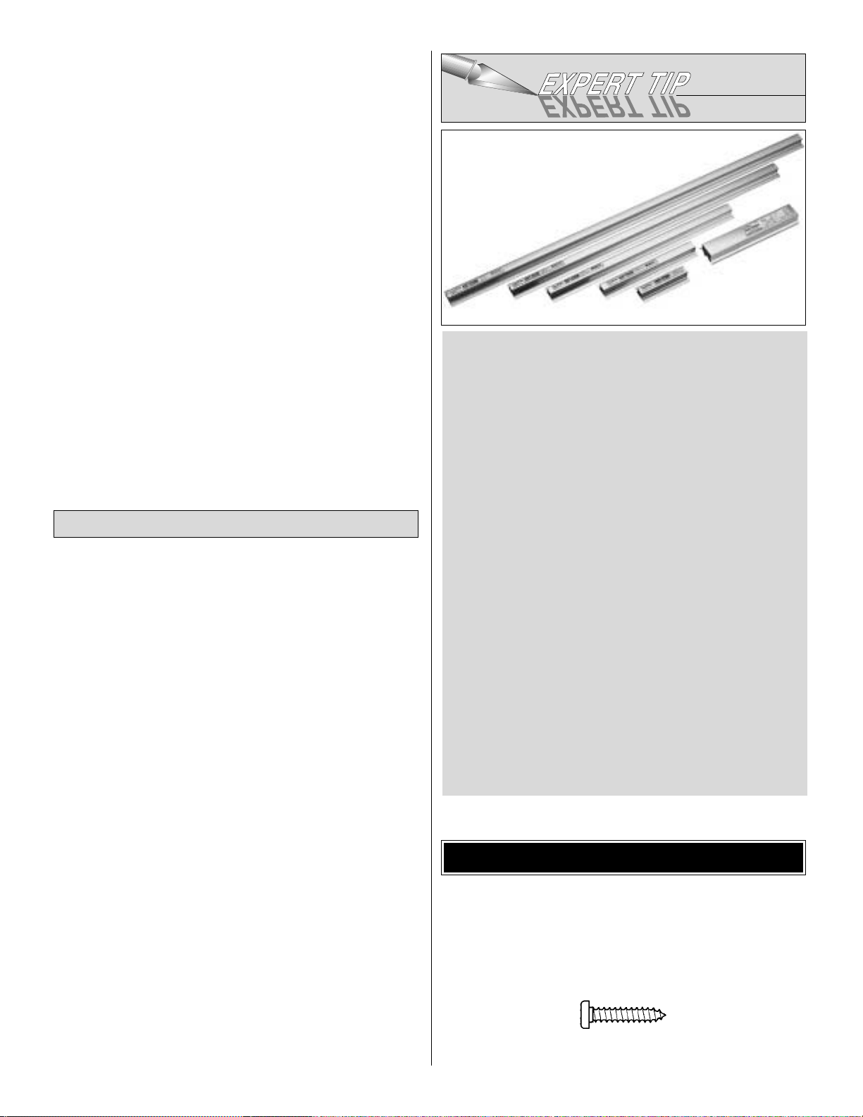
A flat, durable, easy to handle sanding tool is a necessity
for building a well finished model. Great Planes makes a
complete range of Easy-Touch Bar Sanders and
replaceable Easy-Touch Adhesive-Backed Sandpaper.
While building the Ryan STA EP, we used two 5-1/2" Bar
Sanders and two 11" Bar Sanders equipped with 80-grit
and 150-grit Adhesive-backed Sandpaper.
Here’s the complete list of Easy-Touch Bar Sanders and
Adhesive Backed Sandpaper:
5-1/2" Bar Sander (GPMR6169)
11" Bar Sander (GPMR6170)
22" Bar Sander (GPMR6172)
33" Bar Sander (GPMR6174)
44" Bar Sander (GPMR6176)
11" Contour Multi-Sander (GPMR6190)
12' roll of Adhesive-backed 80-grit sandpaper
(GPMR6180)
150-grit (GPMR6183)
180-grit (GPMR6184)
220-grit (GPMR6185)
Assortment pack of 5-1/2" strips (GPMR6189)
We also use Top Flite 320-grit (TOPR8030, 4 sheets) and
400-grit (TOPR8032, 4 sheets) wet-or-dry sandpaper for
finish sanding.
Optional Supplies & Tools
5
Page 6
Machine screws are designated by a number, threads per
inch, and a length. For example 4-40 x 3/4" [19mm].
This is a number four screw that is 3/4" [19mm] long with
forty threads per inch.
• When you see the term
test fit
in the instructions, it means
that you should first position the part on the assembly
without using any glue, then slightly modify or
custom fit
the part as necessar y for the best fit.
• Whenever the term
glue
is written you should rely upon
your experience to decide what type of glue to use.When a
specific type of adhesive works best for that step, the
instructions will make a recommendation.
• Whenever just
epoxy
is specified you may use
either
30-minute (or45-minute) epoxy or6-minute epoxy. When
30-minute epoxy is specified it is highly recommended that
you use only 30-minute (or 45-minute) epoxy, because you
will need the working time and/or the additional strength.
• Photos and sketches are placed before the step they
refer to. Frequently you can study photos in following steps
to get another view of the same parts.
• Not all die-cut parts have a name, or their complete name
stamped on them, so refer to the die drawings on page 7 for
identification. When it’s time to remove the parts from their
die sheets, if they are difficult to remove, do not force them
out. Instead, use a shar p #11 blade to carefully cut the par t
from the sheet, then lightly sand the edges to remove any
slivers or irregularities.Save some of the larger scraps of
wood.
• The easiest way to cut balsa sticks is with a single-edge
razor blade or razor saw. Position the stick over the plan,
mark its size, then cut the part on a piece of scrap wood. A
modeling miter box works well for cutting square corners
and 45° gussets.
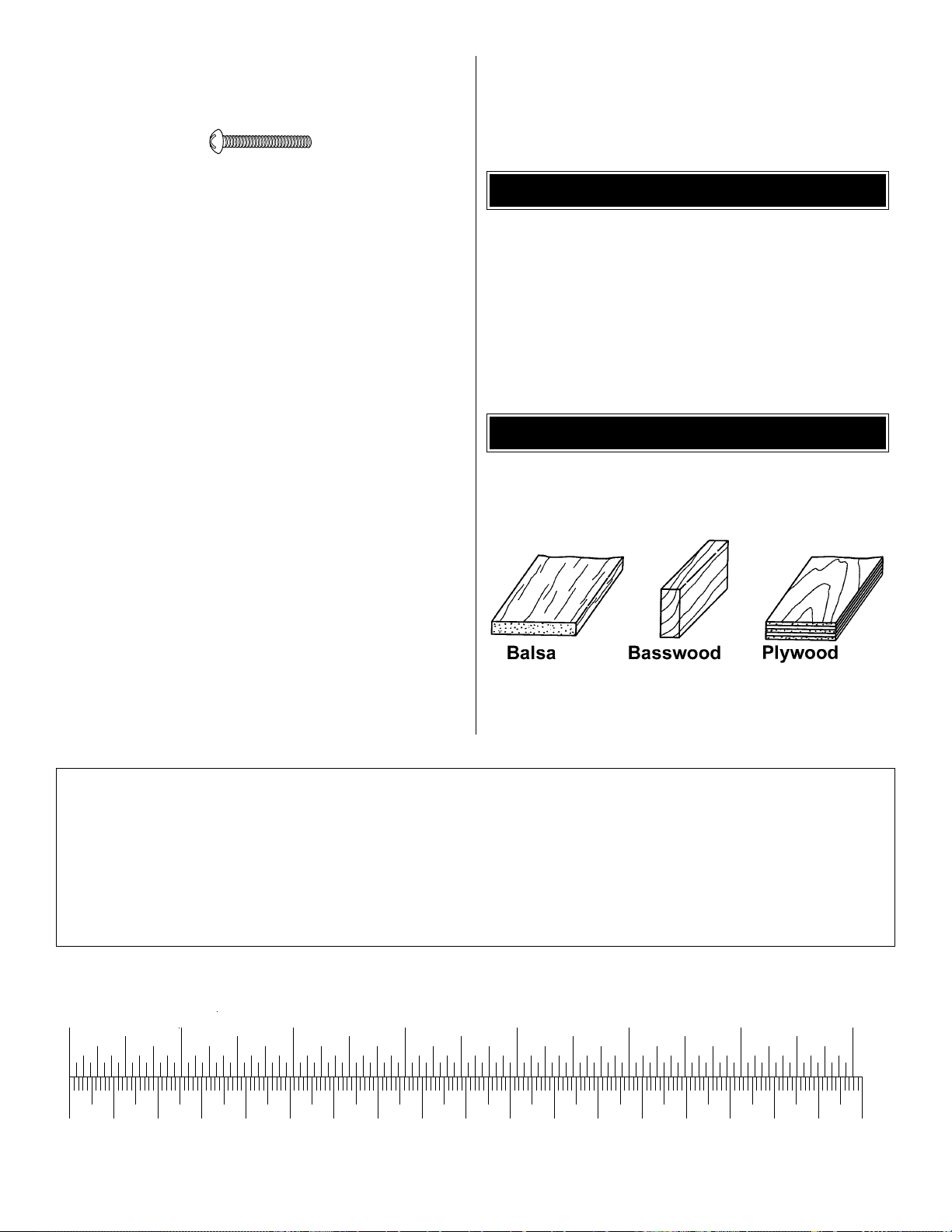
Fuse = Fuselage
Stab = Stabilizer
Fin = Ver tical Fin
LE = Leading Edge
TE = Trailing Edge
LG = Landing Gear
Ply = Plywood
" = Inches
TYPES OF WOOD
COMMON ABBREVIATIONS
6
0" 1" 2" 3" 4" 5" 6" 7"
0 10 20 30 40 50 60 70 80 90 100 110 120 130 140 150 160 170 180
Inch Scale
Metric Scale
1/64" = .4 mm
1/32" = .8 mm
1/16" = 1.6 mm
3/32" = 2.4 mm
1/8" = 3.2 mm
5/32" = 4.0 mm
3/16" = 4.8 mm
1/4" = 6.4 mm
3/8" = 9.5 mm
1/2" = 12.7 mm
5/8" = 15.9 mm
3/4" = 19.0 mm
1" = 25.4 mm
2" = 50.8 mm
3" = 76.2 mm
6" = 152.4 mm
12" = 304.8 mm
18" = 457.2 mm
21" = 533.4 mm
24" = 609.6 mm
30" = 762.0 mm
36" = 914.4 mm
Metric Conversions
Page 7
7
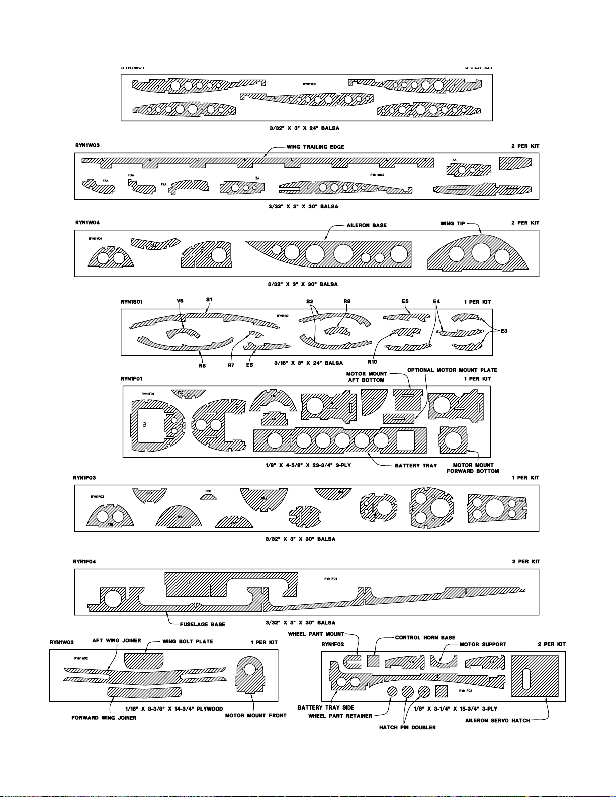
DIE-CUT PATTERNS
Page 8
❏ 1.Unroll the plan sheets.Roll them inside out so they will
lie flat.
❏ 2. Position the fuse plan so the stab plan is over your flat
building board. Cover the plan with Great Planes Plan
Protector or wax paper so glue will not adhere.
❏ 3. From one of the 3/16" x 3/8" x 24" [4.8mm x 9.5mm x
609.6mm] balsa sticks, cut the stabilizer trailing edge and
trailing edge doubler to match the stabilizer plan. Pin the
stab TE ov er the plan and glue the doub ler to the front of the
trailing edge.
❏ 4.Pin the die-cut 3/16" [4.8mm] balsa stabilizer leading
edge (S1) in position. Trim and fit the 3/16" x 3" x 2-1/2"
[4.8mm x 76.2mm x 63.5mm] balsa stabilizer center
between the die-cut LE and the trailing edge doubler. Glue
the stab center to the LE and to the front of the stab TE
doubler.
❏ 5. Pin the two die-cut 3/16" [4.8mm] balsa stab frames
(S2) in position.Glue the frames to the leading edge S1 and
the stab TE.
❏ 6. From the 3/16" x 3/16" x 30" [4.8mm x 4.8mm x
762mm] balsa stick, cut and glue the stab ribs to the stab
frame.
❏ 7. Remove the stab from your building board. Inspect all
the glue joints and add CA to any joints that don’t look
strong. Fill any gaps with balsa sanding dust and a drop or
two of thin CA.
❏ ❏ 1.From a 3/16" x 3/8" x 24" [4.8mm x 9.5mm x
609.6mm]
balsa stick, cut the elevator leading edge to length and pin
it over the ele v ator plan.Pin and glue the die-cut 3/16" balsa
elevator frames E-3 through E-5 to the LE.
Build the Elevator
Build the Stabilizer
BUILD THE T AIL SURF A CES
8
Page 9
❏ ❏ 2.From the 3/16" x 3/8" x 24" [4.8mm x 9.5mm x
609.6mm]
balsa stick, cut and glue the remainder of the frame and the
LE doubler.
❏ ❏ 3.From the 3/16" x 3/16" x 30" [4.8mm x 4.8mm x
762mm]
balsa stick, cut and glue the elevator ribsto the elevator
frame.
❏ 4. Repeat step 1 through step 3 to build the second
elevator half.
❏ 5. Remove the elevators from your building board.
Inspect
all the glue joints and add CA to any joints that don’t look
strong. Sand the stabilizer and elevators to shape using the
fuse plan as a guide. Sand both sides of the stabilizer and
elevator flat and even. Be careful that you don’t sand any
area too thin. Do not bevel the LE of the elevator until after
the hinges have been installed.
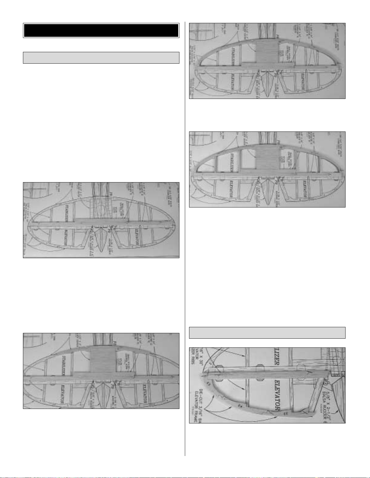
❏ 6. Pin both elevator halves in position over the plan.Lay
the 3/32" elevator joiner wire on top of the elevators in the
position shown on the plan. Use a pencil to lightly mark the
outline of the joiner wire on the elevators.
❏ 7. Using a straightedge, extend the sidelines of the
elevator joiner outline forward to the leading edge.Also, use
a Great Planes Precision Hinge Marking Tool™(GPMR4005)
to draw a centerline on the leading edge of both elevator
halves.Using these lines, you can determine exactly where
to drill the holes for the elevator joiner wire.
❏ 8. Drill a 3/32" hole through the leading edge of both
elevators. As you drill each hole, keep the drill aligned with
the top and bottom surface of the elevator and reference
lines you made in the previous steps.
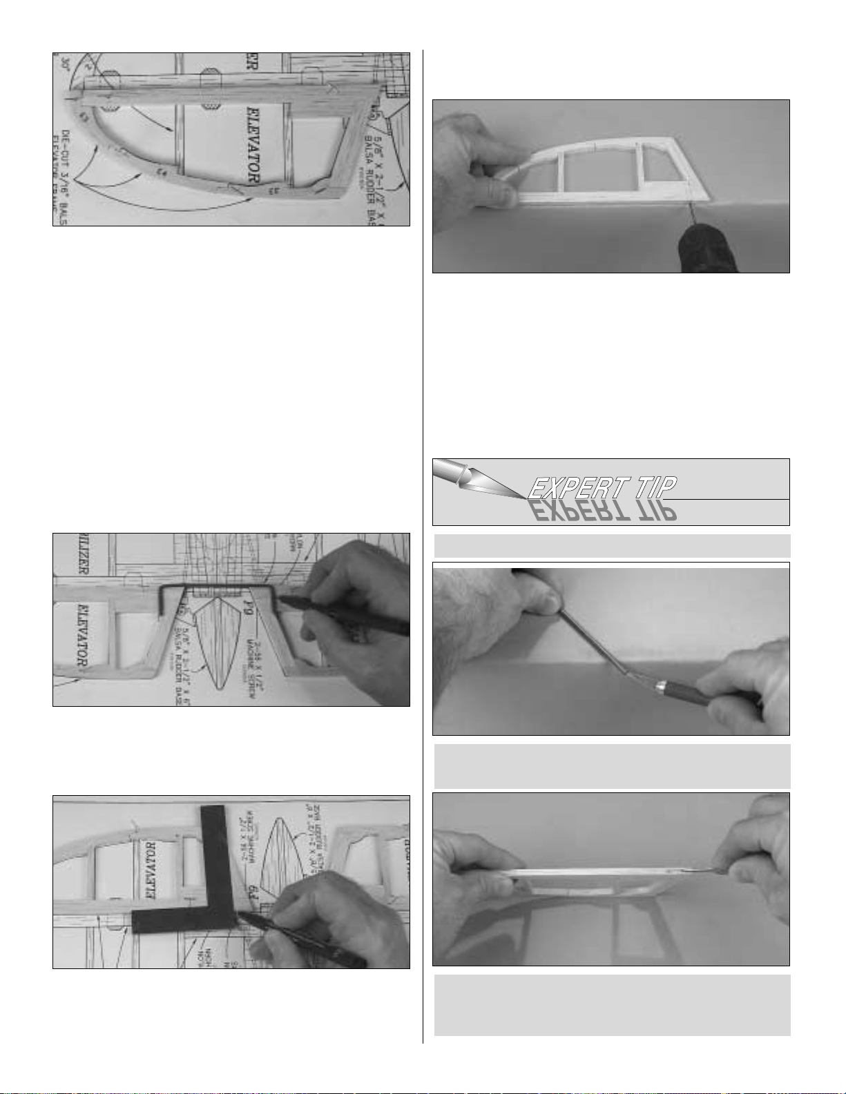
❏ 9. Refer to the
Expert Tip
that follows to cut a 3/32"
groove in the leading edge of both elevators to recess the
joiner wire.
B.Use the sharpened tube to
carefully
gouge the leading
edge of the elevators.You’ll have to make several passes
to make the recess deep enough for the joiner wire.
A. Use a #11 knife blade to sharpen the inside of a piece
of 3/32" brass tube.Roll the tube as you sharpen the end.
HOW TO CUT A GROOVE FOR A JOINER WIRE
9
Page 10
❏ 10.Temporarily join the elevators with the joiner wire.The
joiner wire will be easier to install if you chamfer (bevel) the
ends a little. If necessary, “tweak” the joiner wire so the
elevators are parallel and la y flat on y our building tab le when
the joiner wire is installed. If you found it necessary to
“tweak” the joiner wire, use a felt-tip pen to mark it so you
can install the joiner wire in the same orientation when you
permanently join the elevators.
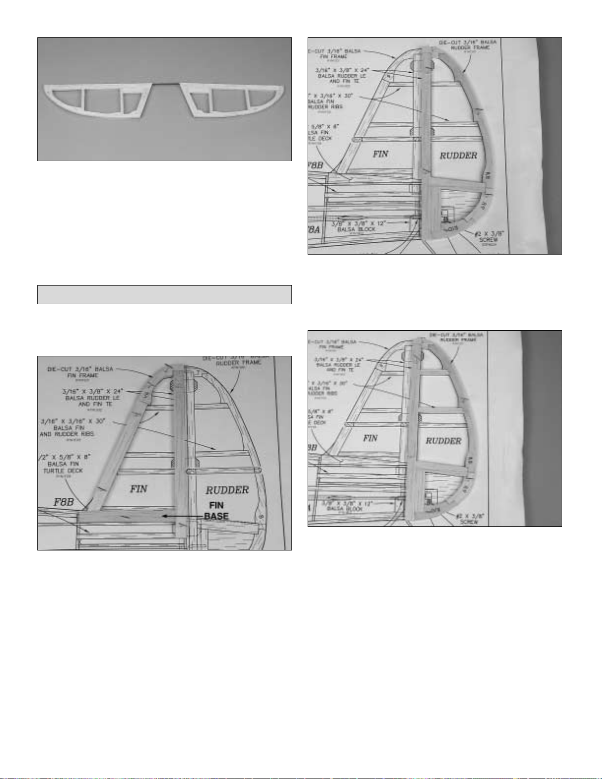
❏ 1. Cover the fin/rudder portion of the plan with waxed
paper or Plan Protector.
❏ 2. Pin the die-cut 3/16" [4.8mm] balsa fin frame V-6 in
position on the fuse plan. From one of the 3/16" x 3/8" x 24"
[4.8mm x 9.5mm x 609.6mm] balsa sticks, cut and glue a LE
and TE to V-6. Cut and glue a fin base, along the bottom of
the fin, between the LE and TE.Also, cut and shape a LE fin
fillet at the bottom of the LE. Note: Cut the TE so that it
extends to the top of the stabilizer.
❏ 3.From the 3/16" x 3/16" x 30" [4.8mm x 4.8mm x
762mm]
balsa stick, cut and glue the fin ribs to the frame. Note that
one of the ribs is glued to the top edge of the fin base.
❏ 4.Remove the fin from your building board.Inspect all the
glue joints and add CA to any joints that don’t look strong.
Fill any gaps with balsa sanding dust and a drop or two of
thin CA.
❏ 5. Build the rudder frame from the die-cut 3/16" [4.8mm]
balsa R-7, R-8, R9 and R-10 frame pieces and a 3/16" x
3/8" [4.8mm x 9.5mm] balsa stick.
❏ 6.From the 3/16" x 3/16" x 30" [4.8mm x 4.8mm x
762mm]
balsa stick, cut and glue the rudder ribs to the frame.
❏ 7. Remove the rudder from your building board. Inspect
all the glue joints and add CA to any joints that don’t look
strong.Sand the rudder and fin to shape using the fuse plan
as a guide. Sand both sides of the r udder and fin flat and
even. Be careful that you don’t sand any area too thin. Do
not sand the bevel on the LE of the rudder until after the
hinges have been installed.
❏ 8. Lay the fin and rudder over the plan and lightly mark
the hinge locations on the LE of the rudder and the TE of the
fin. Repeat the process to mark the hinge locations on the
LE of the elevators and TE of the stab.
Build the Fin & Rudder
10
Page 11
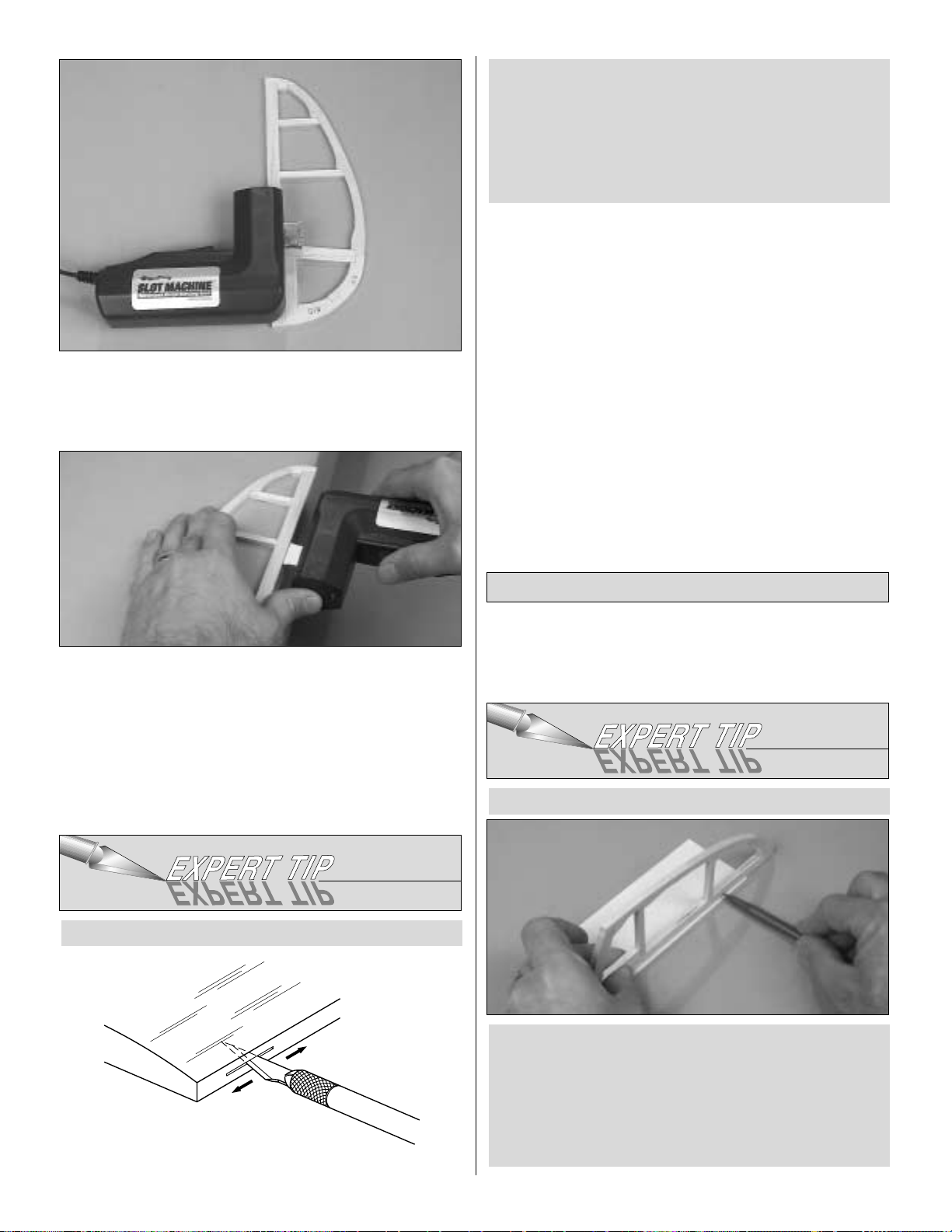
❏ 9. We have simplified the task of cutting hinge slots with
the introduction of the Great Planes Slot Machine™. This
simple electric tool cuts a perfect width slot for use with
CA hinges.
❏ 10.To cut the hinge slot, first locate the center line of the
LE and TE edges using the Great Planes Precision Hinge
Marking Tool (GPMR4005). Then place the blades of the
Slot Machine onto the wood where you want the slot.Lightly
press the teeth into the wood. When you are satisfied with
the location, press the button on the handle and the blades
will cut easily into the balsa wood.
❏ 11. Cut the 1/2" x 1" [12.7mm x 25.4mm] hinges for the
elevator and rudder from the supplied 2" x 9" [50.8mm x
228.6mm] hinge material, then snip off the corners as
shown on the fuselage plan. Temporarily join the elevators
to the stab and the rudder to the fin with the hinges,
adjusting any hinge slots if necessary so they all align. Do
not glue in the hinges until you are instructed to do so
after the airplane is covered.
❏ 1. Refer to the
Expert Tip
that follows and shape the
leading edge of the elevators and rudder to a “V” as shown
on the plan.
A. Place the leading edge of one of the elevators on your
work surface and use your pen to mark a “be v el to”line on
both sides, about 3/32" [2.4mm] high.
Note: You will probably have to adjust the height of the
elevator with card stock so your “bevel to” line is not
too high.
HOW TO BEVEL THE LEADING EDGES
Finish the Tail Surfaces
Cut the hinge slots in the elevators, stabilizer, fin and
rudder using a Hobby Knife with a #11 blade. Begin by
carefully cutting a very shallow slit at the hinge location to
accurately establish the hinge slot. Make three or four
more cuts, going a little deeper each time. As you cut,
slide the knife from side to side until the slot has reached
the proper depth and width for the hinge.
AND #11 BLADE
WITH HOBBY KNIFE
CUT HINGE SLOT
IF YOU DO NOT HAVE A SLOT MACHINE
11
Page 12
❏ 2. Use the same procedure to bevel the leading edge of
the rudder.
❏ 3. Attach the elevators to the stab and the rudder to the
fin. Use your bar sander to round the perimeter of the
elevator, stab, rudder and fin (do not round the bottom edge
of the fin where it will be glued to the stab and fuse and the
bottom half of the rudder where the rudder fairing will be
attached later.
Start by building the right wing panel right side up over the
right wing panel plan so your progress matches the photos.
❏ ❏ 1. Cover the wing panel plan with waxed paper or
Great Planes Plan Protector.
❏ ❏ 2. Glue the die-cut 3-ply landing gear doubler (3LG)
to the die-cut 3/32" [2.4mm] balsa wing rib W3. Make sure
to make a left and right rib.
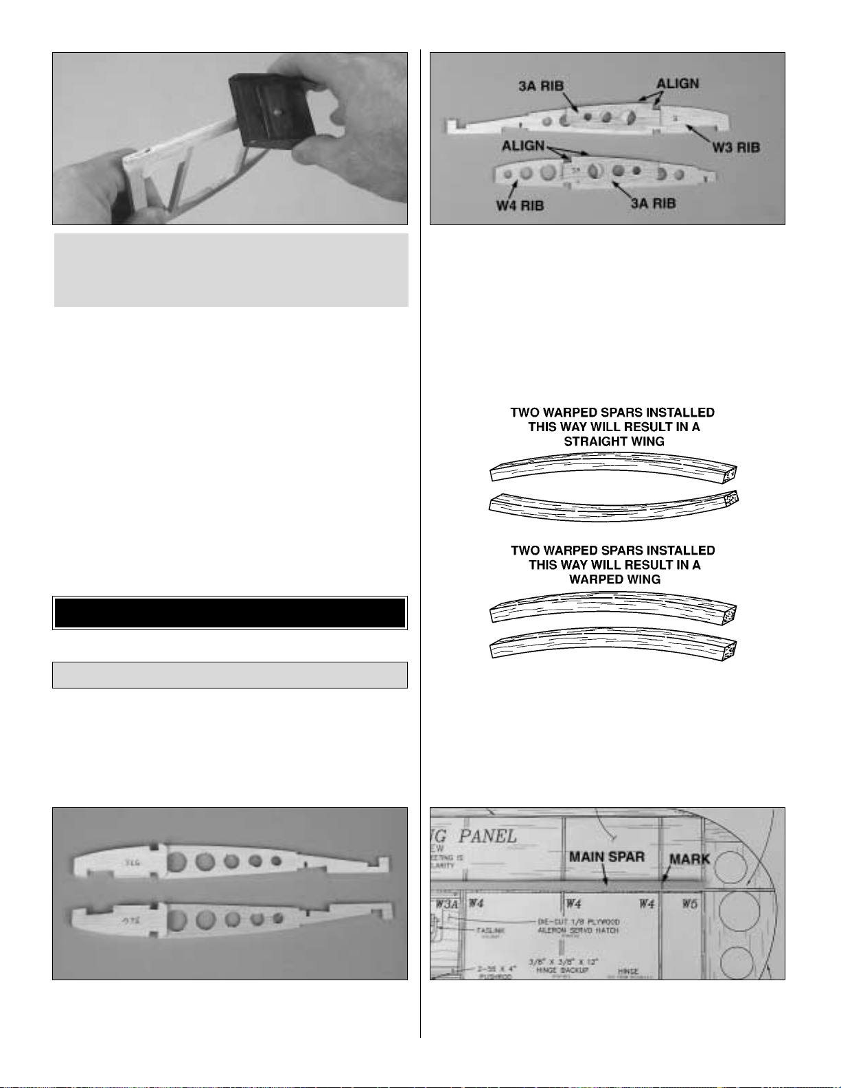
❏ ❏ 3. Glue the die-cut 3/32" [2.4mm] balsa rib doublers
3A to a W3 rib and a die-cut 3/32" [2.4mm] balsa wing rib
W4. Note on the wing plan which side of the ribs the rib
doublers are glued to and that the rib doublers are aligned
with the top of the W3 and W4 ribs.
❏ ❏ 4. Match two of the 1/8" x 1/4" x 30" [3.2mm x 6.4mm
x 762mm] basswood main sparsso any warps will
counteract
each other.
❏ ❏ 5. Position one of the main spars over the plan,
aligning one end of the spar with the outboard edge of the
tip rib W5. Mark the spar at the tip side of rib W4.
Build the Wing Panels
BUILD THE WING
B.Using the “bevel to”lines and the centerline as a guide,
make the “V” on the leading edge of the elevators with a
razor plane or the Great Planes Multi-Sander
(GPMR6190)
with 150-grit sandpaper.
12
Page 13
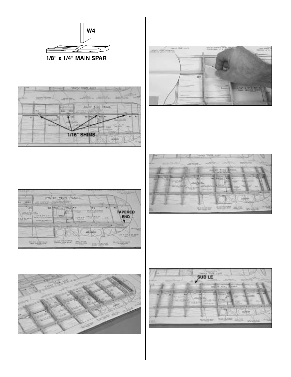
❏ ❏ 6. Cut a V-notch par t way through the spar, at the
mark, so that the spar can bend at W4.
❏ ❏ 7. From one of the 1/16" x 3" x 30" [1.6mm x 76.2mm
x 762mm] balsa sheets, cut four 1/2" x 3/4" [12.7mm x
19mm] shims.Place the shims over the spar location on the
plan, starting between ribs W1 and W2 and alternating
every other rib bay. Pin the main spar, cut in step 6, over the
shims, aligned with the wing plan at the W5 tip rib.
❏ ❏ 8. Pin the die-cut 3/32" [2.4mm] balsa sub trailing
edge, perpendicular to the building board. The tapered end
should be positioned at the wing tip.
❏ ❏ 9. Pin and glue the die-cut 3/32" [2.4mm] balsa W2,
W3, W4 and W5 r ibs onto the main spar and the sub TE,
perpendicular to the building board. The TE of the ribs do
not touch the building board. Note the direction of the W3
ribs with the landing gear doublers and the W3 and W4 ribs
with the rib doublers. The main spar will need to be bent
upward to contact the W5 rib.
❏ ❏ 10. Position the die-cut 3/32" [2.4mm] balsa W1 root
rib over the main spar.Place the die-cut 1/8" [3.2mm] 3-ply
dihedral gauge against the W1 root rib, between ribs W1
and W2. Glue the root rib to the main spar and the sub TE.
Note that the notch in the sub TE is cut at the proper angle.
❏ ❏ 11. Cut a V-notch in the basswood top main spar the
same as you did in the bottom main spar. Glue the top main
spar to the ribs, making sure that the W2 through W5 ribs
are perpendicular to the building board. Also make cer tain
that the main spar is fully seated in each rib.The top of the
main spar should be flush with the front of each rib.
❏ ❏ 12.Center the 3/32" x 1/2" x 30" [2.4mm x 12.7mm x
762mm] balsa sub LE on the front of the r ibs. Check that
the sub TE is against the building board.Then, glue the sub
LE to the front of the ribs.The excess 3/32" x 1/2" [2.4mm x
12.7mm] will be used for the wing tip braces.
13
Page 14
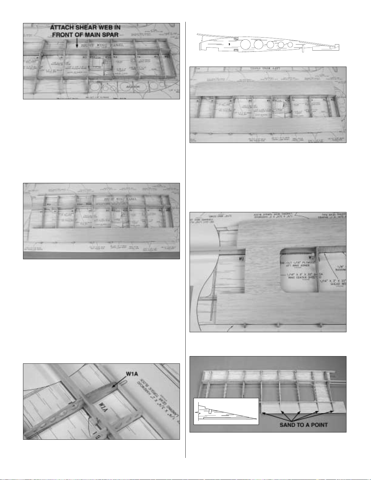
❏ ❏ 13. From the 1/16" x 3" x 30" [1.6mm x 76.2mm x
762mm] balsa sheet that the shims were cut from, cut and
glue vertical grain shear webs to the spars in the locations
shown on the plan.It is not necessary for the shear webs to
be glued to the ribs. Make sure they are glued securely to
the wing spars. Do not install shear webs in the rib bays
between ribs W1 and W3.(The shear web in the aileron bay
should be attached to the front of the main spars.)
❏ ❏ 14.Use a 1/16" x 3" x 30" [1.6mm x 76.2mm x
762mm]
balsa sheet to make the TE sheet. Cut the sheet so that it
is 23" [584mm] long and 2-1/4" [57.2mm] wide. Glue the TE
sheet in the indentations at the aft end of the wing ribs.The
sheet should butt against the aft end of ribs W1 through W3.
Save the 3/4" [19mm] piece you cut off.
❏ ❏ 15. Sand the balsa sub LE flush with the top of
the ribs.
❏ ❏ 16. Glue the die-cut 3/32" [2.4mm] balsa rib doubler
W1A to the inside forward edge of rib W1.
❏ ❏ 17.Cut a 1/16" x 3" x 30" [1.6mm x 76.2mm x 762mm]
balsa sheet 23" [584.2mm] long. Fit the sheet in place,
against the notch in the ribs and on top of the main spar.
Glue the balsa sheet to the main spar and notches. When
the glue has cured, apply a bead of glue to the top of each
rib and along the sub LE. Pull the sheeting down, making
sure it contacts the surface of each rib and sub LE. Hold it
in place until the glue has cured.
❏ ❏ 18. Sheet the center-section with the remaining 7"
[177.8mm] long, 1/16" [1.6mm] balsa sheet cut in the last
step.
❏ ❏ 19.Remove the wing panel from your building board.
Trim and sand the LE sheeting flush with the sub LE. Sand
the LE and TE sheeting, main spars and sub LE flush with
14
Page 15
rib W5.Trim the building tabs off of the bottom of the sub TE.
Trim the TE sheeting stop tabs, at the aft end of the W1, W2
and W3 ribs, to a point. Also sand the aft edge of the TE
sheeting to match the angle of the ribs.T rim the TE sheeting
flush with the sub TE at ribs W4 and W5.
❏ ❏ 20.Trim the main spars flush with rib W1 and sa v e the
excess main spar for use later. Trim and sand the LE
sheeting, TE sheeting, sub LE and sub TE flush with rib W1.
❏ ❏ 21.With the wing upside-down, pin the sub TE to your
building board. Cut a 1/16" x 3" x 30" [1.6mm x 76.2mm x
762mm] balsa sheet 23" [584.2mm] long and 2-1/4"
[57.2mm] wide. Fit and glue the sheet to the ribs, sub TE
and the top TE wing sheeting.
❏ ❏ 22.Sand the balsa sub LE flush with the top of the
ribs.
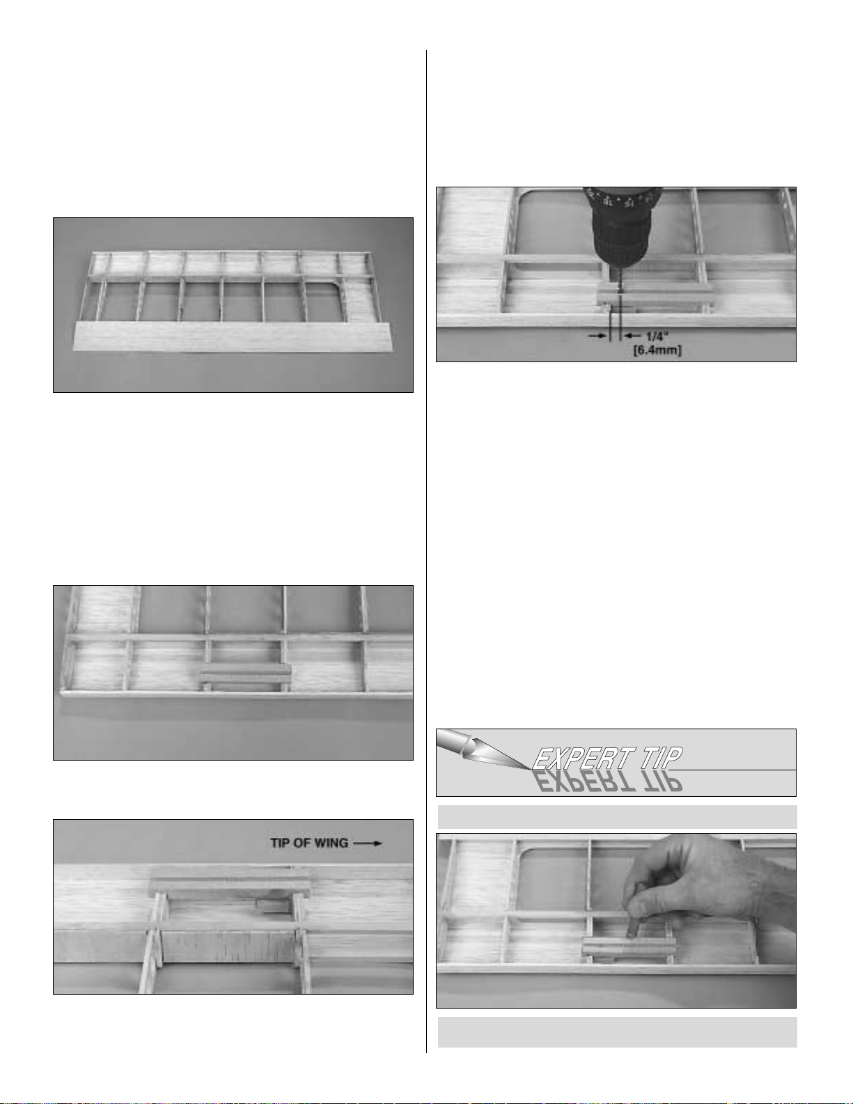
❏ 23. Cut the 1/4" x 3/4" x 7" [6.4mm x 19mm x 177.8mm]
grooved basswood landing gear rail in half.
❏ ❏ 24.Use epoxy to glue the landing gear rail in the
notches,
centered between the W3 ribs.
❏ ❏ 25. Use epoxy to glue the 3/8" x 3/4" x 3/4" [9.5mm x
19mm x 19mm] landing gear torque block to the back of
the landing gear rail and the W3 rib. Make sure the torque
block is glued tow ards the tip end.A couple of T-pins can be
inserted from the top of the wing, through the LE sheeting,
to press the torque block against the landing gear rail.
❏ ❏ 26. Drill an 1/8" [3.2mm] hole, 1/2" [12.7mm] deep
through the landing gear rail and torque block. The hole
should be perpendicular to the landing gear rail and 1/4"
from the W3 rib. Be careful not to drill through the top LE
sheeting.
❏ ❏ 27.Cut a 1/16" x 3" x 30" [1.6mm x 76.2mm x 762mm]
balsa sheet 23" [584.2mm] long for the forward bottom
sheeting. The sheeting must be trimmed to fit around the
landing gear rail so that it fits flush with the top of the rail.
A. Using chalk, mar k the outline of the landing gear rail.
HOW TO LOCATE STRUCTURE UNDER SHEETING
15
Page 16

❏ ❏ 28. Once you have the 1/16" [1.6mm] forward lower
sheeting trimmed to fit around the landing gear rail, glue the
sheeting to the main spar, bottom of the ribs, sub LE edge
and landing gear rail.
❏ ❏ 29. From the 1/16" [1.6mm] balsa sheeting trimmed
from the forward lower sheeting, sheet the center-section.
❏ ❏ 30. Trim and sand the lower sheeting flush with ribs
W1, W5 and the sub LE.
❏ ❏ 31. From the 3/8" x 3/8" x 12" [9.5mm x 9.5mm x
304.8mm] balsa stick cut three 1-1/4" [31.8mm] long hinge
backups.Glue the hinge backups to the front of the sub TE
as shown on the wing plan.
❏ ❏ 32. Glue the 1/4" x 3/4" x 30" [6.4mm x 19mm x
762mm] balsa leading edge, centered on the front of the
sub LE.T rim and sand the LE flush with the W1 and W5 ribs.
The remainder of the 1/4" x 3/4" [6.4mm x 19mm] stick will
be used for the wing tip filler.
❏ ❏ 33. Glue the die-cut 3/32" [2.4mm] balsa wing tips,
perpendicular to rib W5.
C. Cut out the hole for the landing gear rail slightly
smaller.Then, trim the sheeting to fit.
B. Position the sheeting against the notch at the back of
the main spar. Press down on the sheeting around the
landing gear rail. This will leave a chalk mark on the
sheeting.
16
Page 17

❏ ❏ 34.From the remaining 3/32" x 1/2" [ 2.4mm x
12.7mm]
stick used for the sub LE, cut and glue wing tip braces on
the top and bottom of the wing tip.
❏ ❏ 35. From the remaining 1/4" x 3/4" [6.4mm x 19mm]
stick used for the LE, cut and glue wing tip filler blocks on
the top and bottom of the leading and trailing edges.
❏ ❏ 36. Use a razor plane and sanding bar to shape the
LE and wing tip to the shape shown on the wing plan.
❏ 37. Return to step 2 and build the left wing panel.
❏ 1. Draw centerlines along the width and the length of the
two die-cut 1/16" [1.6mm] plywood forward wing joinerand
aft wing joiner.
❏ 2.Using the centerlines as a guide, use epoxy to glue the
forward wing joiner centered on the aft wing joiner.
❏ 3. Carefully cut a slot in the root rib of both wing panels
to allow the wing joiner to be inserted. Also cut a notch,
extending the wing dowel slot through the LE.
❏ 4. Check the fit of the wing joiner in each wing half.The
main spars and TE on both wing halves should meet. With
Join the Wing Panels
17
Page 18

one wing half flat on your building board, block up the other
wing tip 2-1/4" [57.2mm] at the outer most rib W4. Sight
down the wing from the wing tip, chec king that the main spar
and TE are straight. When satisfied with the fit, apply
30-minute epoxy to the back of the main spars, the surface
between the main spars, the front of the aft wing joiner, the
top and bottom edges of the forward wing joiner and the root
ribs. Slide everything back together. Make sure the wing
joiner is inserted to the centerline. Use masking tape to hold
the wing joiner tight against the main spars. Wipe off any
excess epoxy with a paper towel dampened with denatured
alcohol. Check that the one wing is blocked up 2-1/4"
[57.2mm] at rib W4.
❏ 5.From one of the 7" [177.8mm] pieces of 1/16" [1.6mm]
balsa you trimmed for the wing sheeting, cut and glue shear
webs on the back of the aft wing joiner.
❏ 6. Draw a centerline on the top (the side with the punch
mark) of the die-cut 1/16" [1.6mm] plywood wing bolt plate.
Use a sanding bar to bevel the edges as shown. Use a
hobby knife to score along the centerline.This will allow the
wing bolt plate to bend when it is glued to the bottom of
the wing.
❏ 7. Use epoxy to glue the wing bolt plate to the bottom of
the wing. The aft edge of the plate should be flush with the
TE of the wing.
❏ 8. Use a 3/16" [4.8mm] drill bit to enlarge the hole for the
3/16" [4.8mm] wing dowel in the LE of the wing.
❏ 9. Cut the 3/16" [4.8mm] hardwood wing dowel 2-1/4"
[57.2mm] long. Round both ends of the wing dowel and test
fit it in the wing.Do not glue it in until after the wing has been
covered.
❏ ❏ 10. From the remaining 1/8" x 1/4" [3.2mm x 6.4mm]
basswood main spar, cut and glue aileron hatch rails
between the W3A ribs.
❏ ❏ 11.From the remaining 3/32" x 1/2" [2.4mm x
12.7mm]
balsa sub LE, fit and glue a stick to the aft edge of the aft
aileron hatch rail.The stick must be slightly higher than the
bottom of the wing ribs so that it can be sanded flush with
the ribs. This will provide a surface for the covering to be
attached to.
❏ ❏ 12. Position the die-cut 3-ply aileron hatch in the
opening.You may need to sand the edges of the hatch to get
it to fit well. Dr ill 1/16" [1.6mm] pilot holes in each corner of
the hatch and into the rails. Remove the hatch and enlarge
the holes in it to 3/32" [2.4mm]. Countersink the holes in the
hatch to accept the #2 x 3/8" flat head screws. A Dremel
High Speed Steel Cutter #178 will make countersunk holes
easy. Secure the hatch to the hatch rails with the screws.
18
Page 19

Then, remove the hatch and put a drop of thin CA in each
hole in the rails to harden the wood.After the CA has cured,
replace the hatch and screws.
❏ 13.Go back to step 10 and install the other aileron hatch.
❏ ❏ 1. Position the die-cut 3/32" [2.4mm] balsa aileron
base
over the plan.Mark the aileron rib locations on both sides of
the aileron base.
❏ ❏ 2.Cut the 1/4" x 1/2" x 24" [6.4mm x 12.7mm x
609.6mm]
balsa aileron LEin half. Draw a centerline lengthwise on the
1/2" x 12" [12.7mm x 304.8mm] side.
❏ ❏ 3. Glue the aileron base on the aileron LE along the
centerline and perpendicular to the face of the LE.
❏ ❏ 4. From the 3/32" x 1/4" x 24" [2.4mm x 6.4mm x
609.6mm] balsa sticks, cut and glue aileron ribs to both
sides of the aileron base, perpendicular to the base.
❏ ❏ 5. Trim the ends of the aileron LE and r ibs flush with
the aileron base.
❏ ❏ 6. From the remaining 1/4" x 3/4" x 30" [ 6.4mm x
19mm x 762mm] balsa stick, cut and glue aileron tip fillers
on the top and bottom of the aileron.
❏ ❏ 7. Use a razor plane and sanding bar to shape the
aileron ribs and LE to shape.
❏ ❏ 8. Position the die-cut 3-ply aileron horn base on the
aileron LE. Mark the outline of the base on the LE. Carefully
trim a recess in the LE so that the base is flush with the LE
and the aileron rib.
❏ ❏ 9. Glue the hor n base to the LE and the rib. Make a
small wedge from leftover 3/32" [2.4mm] balsa to fit
between the horn base and the aileron base.
❏ ❏ 10. Position the aileron on the wing and mark the
location of the hinges on the aileron and wing.
Assemble the Ailerons
19
Page 20

❏ ❏ 11. Draw a centerline on the LE of the aileron and the
TE of the wing.
❏ ❏ 12.Cut the hinge slots in the aileron and the wing. Cut
three 1/2" wide hinges from the supplied hinge strip and trim
the corners. Insert the hinges in the aileron and fit the
aileron to the wing.Do not glue the hinges until instructed to
do so.
❏ ❏ 13.Remove the aileron from the wing.Mark the “bevel
to” lines on both sides of the aileron, 3/32" from the LE.
Shape the LE of the aileron to a “V” as shown on the plan.
❏ ❏ 14. Temporarily attach the aileron to the wing. Sand
the tip of the aileron to match the shape of the wing tip.
❏ 15. Retur n to step 1 of
“Assemble the Ailerons”
and
build the second aileron.
❏ 1. Cover the fuselage plan with waxed paper or Great
Planes Plan Protector. When installing the formers, make
sure the enbossed lettering is always facing forward.
❏ 2. Glue the two die-cut 3/32" [2.4mm] balsa fuselage
bases together. Pin the base over the fuselage top view.
❏ 3. Glue the die-cut 3-ply former F2C to the front of F2A.
Make sure the wing dowel holes are aligned.
❏ 4. Glue former F2A perpendicular to the fuselage base
so that F2C is toward the front and F2A is positioned at the
front of the slot.
❏ 5.Glue the two die-cut 3/32" [2.4mm] balsa former halves
F6A together.
❏ 6.Glue the two die-cut 3/32" [2.4mm] balsa doublers F6D
to the back of former F6A.
Assemble the Fuselage Bottom
BUILD THE FUSELAGE
20
Page 21

❏ 7. Glue former F6A perpendicular to the fuselage base
with formers F6D towards the aft end of the fuselage.
❏ 8. Glue the two die-cut 3-ply wing saddles between
formers F2A and F6A. Make sure the wing saddles are fully
seated in the slots.
❏ 9. Glue the die-cut 3-ply former F1A to the front of the
wing saddle and the fuselage base. Make sure the
embossed
F1A
faces forward. Note: The front of the wing
saddle will provide approximately 2 degrees of down thrust
when the motor is installed.
❏ 10. Glue the die-cut 3-ply wing bolt plate (WBP) to the
wing saddle and former F6A.
❏ ❏ 11.Glue the die-cut 3-ply battery trayto the top of the
wing saddle and formers F1A, F2A and F3A.
❏ 12. Glue the die-cut 3/32" [2.4mm] balsa formers F4A to
the wing saddle and the fuselage base. The former should
be flush with the bottom of the wing saddle.
21
Page 22

❏ 13. Glue the die-cut 3/32" [2.4mm] balsa formers F3A to
the wing saddle.
❏ 14. Glue the die-cut 3/32" [2.4mm] balsa formers F5A to
the wing saddle.
❏ 15. Glue the die-cut 3/32" [2.4mm] balsa former F7A
perpendicular to the fuselage base.
❏ 16. Glue the die-cut 3/32" [2.4mm] balsa former F8A
perpendicular to the fuselage base.
❏ 17. Cut and glue a 3/8" x 3/8" [9.5mm x 9.5mm] stick to
the front of the die-cut 3/32" [2.4mm] balsa former F9.The
stick is centered on the former and runs from the stab
saddle slot to the bottom of the former.
❏ 18.Glue the die-cut 3/32" [2.4mm] balsa lower stabilizer
saddle (LSS) to former F8A and F9. Glue former F9 to the
fuselage base aligning the fin slot in the base with the fin
slot in F9.
❏ 19. Glue the 3/16" [4.8mm] balsa upper and lower side
stringers in the notches from former F1A to F9. A notch
needs to be cut in the stringers at former F6A to allow the
stringers to bend past the former without bowing out in front
of the former. Note that the lower side stringer ends at
former F7A.
22
Page 23

❏ 20. Glue the 3/16" [4.8mm] balsa aft bottom stringers
between F6A and F9. Glue the 3/16" [4.8mm] balsa forward
bottom stringers between F1A and F2A.
❏ 21. Use a sanding bar to sand formers F3A, F4A and
F5A flush with the wing saddle. From a 1/16" x 3" x 30"
[1.6mm x 76.2mm x 762mm] balsa sheet, cut and glue
cross-grain wing saddle sheeting to the 3-ply wing saddle
and formers F3A, F4A and F5A.
❏ 22.Carefully sand the edges of the wing saddle sheeting
by using the contour of the formers as a guide.Trim the wing
saddle sheeting from between the 3-ply wing saddle.
❏ 1. Use a sanding bar to sand the stringers flush with the
formers.
❏ 2. Tr im a 1/16" x 3" x 30" [1.6mm x 76.2mm x 762mm]
balsa sheet to fit between F1A and F6A. Note: Do not glue
the forward lower sheeting to formers F6D, which is glued
behind F6A. The sheeting should be glued so that it only
covers the bottom half of the top stringers. Cut a second
sheet to fit on the other side. The remaining 1/16" [1.6mm]
balsa sheet will be use on the aft end of the fuselage.
❏ 3. From the remaining sheeting cut in step 2, trim and
glue the aft lower sheeting between F6D and F9.
❏ 4.Trim and sand the lower sheeting flush with the bottom
of the formers and wing saddle sheeting.
❏ 5. From the 1/8" x 3" x 30" [3.2mm x 76.2mm x 762mm]
balsa sheet, cut the aft bottom deck as shown on the fuse
plan, and glue it to the bottom stringers and formers.
Sheet the Lower Half of the Fuselage
23
Page 24

❏ 6. From the remaining 1/8" x 3" x 30" [3.2mm x 76.2mm
x 762mm] sheet cut in step 5, trim and glue a forward
bottom deck to formers F1A, F2A and the lower forward
sheeting.
❏ 7. Trim the bottom deck flush with the lower sheeting.
❏ 8.
Congratulations!
You have half of the fuselage built.
Remove the fuse from your building board and let’s get
started on the top of the fuse.
❏ 1. Cut the gray plastic outer pushrod tube in half. Use
320-grit sandpaper to roughen the pushrod tube.
❏ 2. Inser t the outer pushrod tubes through formers F6A,
F7A and up to F8A. Use a T-pin to locate the notch in F8A.
Then, carefully cut slots for the outer pushrod to exit. A
sharpened 3/16" [4.8mm] brass tube can also be used to
cut the slot.
❏ 3. Adjust the pushrod tubes so that the ends are
protruding 1/8" [3.2mm] in front of former F6A. Glue the
pushrod tubes to the formers and the lower sheeting. The
slots in the side of the fuse for the pushrod tube exit can be
filled with Hobbico balsa filler or a 50/50 mixture of
microballoons and epoxy. After the filler has cured, cut off
the excess pushrod tube and sand the tube and filler flush
with the fuselage sheeting.Save the excess tubes for use in
attaching the battery hatch.
❏ 1.Glue 3/16" x 3/16" [4.8mm x 4.8mm] stringers between
formers F8A and F9.
❏ 2. Sand the stringers so that they match the contour of
formers F8A and F9.
❏ 3.Glue the die-cut 3/32" [2.4mm] balsa former F6C to the
back of F6B.
❏ 4. Glue the die-cut 3/32" [2.4mm] balsa formers F2B,
F6B, F7B and F8B, perpendicular to the fuselage base.
Note: F6B should be positioned so that F6C is toward the
tail of the plane.
Finish the Top of the Fuselage
Install the Outer Pushrod Tubes
24
Page 25

❏ 5.Glue 3/16" x 3/16" [4.8mm x 4.8mm] stringers from
former
F6B to F8B.The stringers glue to the front of former F8B.
❏ 6.Use a sanding bar to remove any excess glue from the
joint between former F1A and the fuselage base. Glue the
die-cut 3-ply former F1B to the top of F1A. Use a
straightedge to make sure that F1B is in line with F1A.
❏ 7. Glue 3/16" x 3/16" [4.8mm x 4.8mm] balsa stringers
from F1B to F2B.Make sure that F2B is perpendicular to the
fuselage base.
❏ 8. Use a sanding bar to sand the edges of the fuselage
base flush with the edge of the formers.Part of the stringers
will need to be sanded at former F8B.
❏ 9. As on the bottom of the fuselage, sheet the top of the
fuselage with 1/16" x 3" x 30" [1.6mm x 76.2mm x 762mm]
balsa sheeting.Wetting the sheeting with water will allow the
sheeting to bend around the tight radius at the aft end of
the fuse.
❏ 10.Trim and sand the upper fuselage sheeting flush with
the face of formers F1A and F9. Cut out the battery hatch
area.Sand the top of the sheeting and stringers flat with the
top of formers F1B and F2B and F6B and F8B.
❏ 11.From the remaining 1/8" x 3" x 30" [3.2mm x 76.2mm
x 762mm] balsa sheet, cut in step 5 of
“Sheet the Lower
Half of the Fuselage,”
fit and glue the top deck to the
stringers and upper sheeting.
❏ 12. Use a razor plane and sanding bar to shape the
fuselage
as shown in the cross-section drawings on the fuse plan.
❏ 1. Sand the fuselage base smooth in the area for the
battery hatch cover.
❏ 2. Glue the die-cut 3/32" [2.4mm] balsa battery hatch
base halves together.
❏ 3. Glue the two die-cut 3-ply hatch pin doublers under
the fuselage base as shown on the fuse plan.
Build the Battery Hatch Cover
25
Page 26

❏ 4. Glue the other two hatch pin doublers to the top of the
battery hatch base.
❏ 5. Center the batter y hatch base on the fuselage base.
The opening in the battery hatch base goes towards the
front of the fuselage. Use T-pins to hold the hatch base in
position.
❏ 6. Drill a 3/16" [4.8mm] hole at both punch marks in the
hatch pin doublers, perpendicular to the battery hatch base.
The hole goes through the hatch pin doubler, battery hatch
base, fuselage base and the second hatch pin doubler.
❏ 7. Cut the remaining 3/16" [4.8mm] hardwood dowel in
half. Round one end of each dowel. Remove the battery
hatch base and insert the two dowels in the bottom of the
battery hatch base and hatch pin doublers.
❏ 8. Place a piece of plan protector or waxed paper in the
battery hatch area and make a hole in the protector at both
pin holes. Reinstall the battery hatch base, centered in the
opening. Glue the hatch pins to the hatch base and hatch
pin doublers.
❏ 9. Glue the die-cut 3/32" [2.4mm] balsa backrest front
(BRF) to the front of the back rest (BR).
❏ 10. With the battery hatch base flat against the fuselage
base, glue the back rest in the slot at the aft end of the
battery hatch base. Make sure the back rest is against
former F6B.
❏ 11. Drill a 3/16" hole at the punch mar k in the backrest
front, perpendicular to the backrest front. The hole should
go through the backrest front, backrest, F6B and F6C.
❏ 12.Remove the battery hatch and glue a piece of
remaining
gray outer pushrod tube in former F6B and F6C. Also, glue
a piece of tubing in the backrest. Sand the tubing flush with
the back of the backrest and the front of former F6B.
❏ 13. Cut a 3/4" [19mm] long retainer pin from the 6-1/2"
[165mm] white inner pushrod tube. Place a #2 washer on a
#2 x 3/8" sheet metal screw. Thread the screw into the
plastic retainer pin.
❏ 14. With the plan protector under the battery hatch,
reinstall the hatch on the fuse. Secure the battery hatch to
26
Page 27

the fuse by temporarily inserting the retainer pin through the
backrest.
❏ 15. Glue the two die-cut 3/32" [2.4mm] balsa instrument
panels (IP) to the battery hatch base. The center panel
should be glued perpendicular to the base. The front panel
should be against former F2B.
❏ 16. Glue stringers between the two instrument panels.
❏ 17. Remove the battery hatch and sand the edges of the
hatch base flush with the backrest and instrument panels.
❏ 18. Reinstall the battery hatch with the plan protector
under it. From the remaining 1/16" balsa sheet, glue
sheeting on both sides of the battery hatch from the forward
instrument panel to the back rest.
❏ 19. Sand the top of the sheeting and stringers flush with
the top of the instrument panels. Do not sand the sheeting
on the backrest.
❏ 20. Glue the remaining 1/8" x 3" [3.2mm x 76.2mm]
sheeting to the top of the battery hatch from the forward IP
to the aft IP. Trim and sand the top sheeting flush with the
side sheeting.
❏ 21. Place the battery hatch on the fuselage. Sand the
hatch to match the fuselage sides. Balsa filler can be used
to fill any gaps between the hatch and the fuselage.
❏ 1. Glue the die-cut 3-ply left and right motor mount
sides
perpendicular to the forward bottom motor mount.
Note that
the
forward bottom motor mount has a notch that
faces the
front.
❏ 2.Glue the die-cut 1/16" plywood motor mount front to
the
sides and bottom.Reinforce the glue joints with medium CA.
Build the Motor Mount
27
Page 28

❏ 3. Install and glue the motor mount to former F1. When
viewed from the top, the mount should angle to the right.
❏ 4. Insert and glue the die-cut 3-ply motor support in the
notch of the die-cut 3-ply motor mount aft bottom. Check
that the motor support is per pendicular to the motor mount
aft bottom.
❏ 5. Glue the aft bottom motor mount between the sides.
The tabs on the motor mount aft bottom should be against
the angled part of the motor mount sides. The motor mount
aft bottom should also be tight against former F1A.
❏ 1. Position the wing in the wing saddle and visually align
it with the fuselage.
❏ 2. Use a tape measure to measure the distance from the
corner of the aileron bay to the center of the tail. Then,
measure the distance from the other aileron bay and check
that the distances are the same. Adjust the wing until both
distances are equal. When the wing is perfectly aligned,
make reference marks on the wing TE and the bottom of the
fuselage to help keep the parts aligned during the next step.
❏ 3.Tape the wing in position so that it cannot move. Use
a 13/64" [5.1mm] (or #10) drill bit to drill a hole through the
wing and the bolt plate in the fuselage, at the punch mark
on the wing bolt plate.Two small 90° tr iangles will help you
to align the drill perpendicular to the top surface of the wing.
Mount the Wing on the Fuselage
28
Page 29

Important: Do not allow the wing to shift during this
procedure.
❏ 4. Remove the wing and use a 1/4" [6.4mm] drill bit to
enlarge the hole in the wing only.
❏ 5.Use a 1/4-20 tap to cut threads into the bolt plate. After
cutting the threads, put a couple of drops of thin CA on the
threads in the bolt plate. Allow the CA to cure before
threading the tap back through the hole to clean up the
threads. Bolt the wing to the fuse with a nylon 1/4-20 wing
bolt and check the fit.
❏ 1.Looking at former F9, note the location of the stabilizer
saddle and the 3/16" x 3/16" [4.8mm x 4.8mm] stringers
above the stabilizer saddle. Cut the fuselage sheeting
between the stringers and stabilizer saddle.
❏ 2. Inser t the stabilizer in the fuselage. Measure from the
tip of the stabilizer to the fuselage on both sides to center it.
Measure from the center of the front of the fuselage back to
both stabilizer tips. Adjust the stabilizer so that both
measurements are the same.The LE of the stabilizer should
be against the back of former F8A. With the wing mounted
to the fuselage, view the stabilizer from a f ew f eet behind the
fuselage. Check that the stabilizer is parallel to the wing. If
not, remove the stabilizer and sand the stabilizer saddle
slightly. Use a piece of 3-ply left over from a die sheet with
a piece of 220-grit sandpaper attached.When satisfied with
the fit, insert the elevator joiner wire in the slot. Then,
use 30-minute epoxy to glue the stab to the fuselage.
Double-check the stab alignment while the epoxy is curing.
Wipe off any excess epoxy with a paper towel dampened
with denatured alcohol.Check that the elev ator joiner wire is
not glued to the stab.
❏ 3. Using the joint between the two fuselage base halves,
mark the center of the top deck.
❏ 4.Cut the 1/2" x 5/8" x 8" [12.7mm x 15.9mm x 203.2mm]
balsa stick in half to make two fin fairings.Cut a remaining
Mount the Stabilizer & Fin
29
Page 30

piece of 3/16" x 3/8" balsa stick to make a dummy fin to fit
between the two fairings.
❏ 5. Using only one or two drops of CA, tack glue the
fairings to the dummy fin.Make sure one of the ends and the
bottoms of the fairings are flush.
❏ 6. Tack glue the fairings and the dummy fin to the
fuselage base.Make sure that the dummy fin is aligned with
the slot in former F9 and the center mark on the top deck.
❏ 7. Trim and sand the fairings to match the contour of the
fuselage.
❏ 8.Cut the 3/4" x 2-1/2" x 6" [19mm x 63.5mm x 152.4mm]
balsa block in half to make two rudder fairings. Cut two
pieces from the remaining piece of 3/16" x 3/8" balsa stick
to make a dummy rudder to fit between the two fairings.
❏ 9. Using only one or two drops of CA, tack glue the
fairings to the dummy rudder. Make sure one of the ends
and the bottoms of the fairings are flush.
❏ 10.Tack glue the fairings and the dummy rudder to
former
F-9. Make sure that the dummy rudder is aligned with the
slot in former F9.
❏ 11.Trim and sand the fairings to match the contour of the
fuselage.
❏ 12. Remove the fairings from the fuselage and break
them off of the dummy fin and rudder.
30
Page 31

❏ 13. Test fit the fin in the fuselage base.You may need to
sand the bottom end of the TE to allow the bottom of the fin
to fit tightly against the base. Align the LE of the fin with the
center mark on the top deck. Use a builders triangle to
check that the fin is perpendicular to the stab. When
satisfied with the fit, use 30-minute epoxy to glue the fin to
the fuselage base, former F9 and F8B. Before the epoxy
cures, recheck that the fin is perpendicular to the stab.
❏ 14. Use 6-minute epoxy to glue the two fin fairings to the
side of the fin and the fuselage base.
❏ 15. Mark the location of the tailgear wire on the rudder
and the nylon tailgear bearing on the fuselage.
❏ 16. Dr ill a 3/32" hole in the LE of the rudder at the mark
you made for the tailgear wire. Then, cut a groove for the
nylon tailgear bearing.Test fit the tailgear wire in the rudder.
❏ 17. Cut a slot in the aft edge of former F9 at the marks
you made for the tailgear bearing. Without using any glue,
join the rudder to the fuse.
❏ 18. Glue the two rudder fairings on the bottom of the
rudder, aligned with the fuselage.
❏ 19.Remove the rudder from the plane.Trim and sand the
rudder fairings to match the shape of the rudder. Bevel the
fairings to match the angle of the leading edge.
31
Page 32

❏ 1. Install the elevator and rudder servos in the servo tray
using the hardware provided with the servos. Note their
orientation in the photo.
❏ 2. From the 6-1/2" white nylon inner pushrod, cut eight
1/8" [3.2mm] long bushings.
❏ 3. Make a rudder and an elevator pushrod by cutting
two 2-56 x 36" [914.4mm] pushrods so that each is 22"
[558.8mm] long measured from the threaded end.
❏ 4. Wipe the pushrods off with a paper towel dampened
with denatured alcohol to remove any oil left on the rods
during manufacturing. Slide four bushings evenly spaced
onto each pushrod. Adjust the bushings nearest the ends of
the rod so they will not interfere with the ends of the outer
pushrod tube and possibly become jammed during flight. If
the bushings slide onto the rods without much resistance,
use a drop of thin CA to hold them in position.
❏ 5.Thread a nylon clevisapproximately 14 turns onto the
threaded ends of the pushrods. Remove the backing plate
from one of the small control horns and connect the
control horn to the clevis on one of the pushrods. Inser t the
pushrod in the rudder pushrod tube on the left side of the
fuse. Position the control horn on the rudder fairing and
mark the control horn location on the fairing.
❏ 6. Position a 3-ply control horn base over the control
horn location. Mar k the outline of the control horn base on
the fairing. Carefully tr im the fairing so that the control horn
base can be recessed into the fairing, flush with the top of
the fairing.When satisfied with the fit, glue the control horn
base to the fairing.
❏ 7.Attach the rudder control horn to the control horn base
with two #2 x 3/8" [9.5mm] sheet metal screws.Remove
the two screws and put a drop of thin CA in each hole to
harden the wood. After the CA has cured, reinstall the
control with the #2 x 3/8" [9.5mm] sheet metal screws.
❏ 8. Attach the elevator halves to the stabilizer. Attach a
small control horn on the second pushrod and insert it in the
elevator pushrod tube. Position the control horn on the
elevator as shown on the plan. Mark the location of the
control horn mounting holes and drill 3/32" [2.4mm] holes at
the marks. Temporarily mount the elevator control horn on
the elevator with the bac king plate and 2-56 x 1/2"
[12.7mm]
machine screws.
INCORRECTCORRECT
HINGE LINE
Install the Servos
RADIO INSTALLATION
32
Page 33

❏ 1. Our plane flew great using the Great Planes GD-600
geardrive (GPMG0850). If you would prefer to use a 600
size motor on direct drive, drill the mounting holes in the
motor front plate to match the mounting screw size for your
motor. Most motors require an 1/8" [3.2mm] hole. Slide the
die-cut 3-ply optional motor mount plate through the side
of the motor mount.Insert the second 3-ply motor support in
the optional motor mount plate.Mount the motor to the front
plate with the mounting screws sized for your motor.
❏ 2. If you are using the recommended Great Planes GD-
600 geardrive system (GPMG0775) with a S-60014R motor
and C-30 electronic speed control, attach the geardrive to
the front of the motor and solder the capacitors and wires,
from the ESC, to the back of the motor , as sho wn in the ESC
instructions. Use a 7/64" [2.7mm] drill bit to drill mounting
holes at the punch marks in the front plate. Install the
motor/geardrive in the motor mount using two #4 x 3/8"
[9.5mm] sheet metal screws. Wrap two #64 rubber bands
around the motor and motor mount.
❏ 3. Use Velcro Hook and Loop material to mount the
speed control on the side of the fuselage. The material will
adhere better if you first apply thin CA to the balsa sheeting
and allow it to cure before applying it.Plug the ESC, rudder
and elevator servos into the receiver.After the C.G. location
is checked and the motor battery location is determined, the
receiver can be attached to the fuselage side similar to the
ESC. On our show model, we waited until after the model
was covered to install the on/off switch from the ESC. We
installed it in the center of the black stripe on the side of the
fuselage.
❏ 4.Connect the 8.4 volt motor battery into the ESC.Switch
on the transmitter, then the ESC, and center the trims on
your transmitter and the servo arms on the rudder and
elevator servos.
❏ 5. With the servos centered and the control surfaces in
neutral position, use a felt-tip pen to mark where the
elevator and rudder pushrods cross the mounting holes in
the servo arms. Note: The servo arms have been painted
for clarity.
Install the Motor & Speed Control
33
Page 34

❏ 6. Disconnect the clevises from the control horns. Make
a 90° bend at the marks you made. Temporarily install a
nylon Faslink™on each pushrod and cut the wire so it
slightly protrudes out of the Faslink. Hint: If you prefer to
bend and cut the pushrods out of the fuselage, remove the
clevis, pull the pushrod out, make the 90° bends at the
marks and cut the rods.Reinstall the pushrods in the
pushrod
tubes from the front and screw the clevises back on.
Note: If necessary, enlarge the holes in the servo arms with
a 5/64" [1.9mm] drill bit (or a #48 drill for precision).
❏ ❏ 1. Remove the aileron servo hatch from one of the
wing halves. Position the servo on the hatch so that the
servo arm is centered in the hatch opening. From the 1/4" x
3/8" x 6" [6.4mm x 9.5mm x 152.4mm] basswood stick, cut
two servo mounting bloc ks 1/2" [12.7mm] long.Use 30-
minute
epoxy to glue the servo mounting blocks to the servo hatch.
Note: Secure the servo mounting blocks by first drilling
several 1/16" [1.6mm] holes about 1/8" [3.2mm] deep into
the gluing surface of the basswood blocks. Roughen the
servo hatch where the epoxy will be applied. Pack epoxy
into the 1/16" [1.6mm] holes before clamping the bloc ks into
position.
❏ ❏ 2.After the epoxy has fully cured, insert a 1/32"
[.8mm]
temporary shim between the servo and the plywood hatch.
Drill 1/16" [1.6mm] pilot holes and mount the servos to the
mounting blocks using the hardware that came with the
servos. Remove the shims.
❏ ❏ 3. Trim a servo arm so that only one arm remains.
Install the servo arm on the servo and reinstall the hatch in
the wing.
❏ ❏ 4. Connect a 12" [304.8mm] servo extension to the
aileron servo.Cut a small exit hole for the servo wires in the
top wing sheeting, at the center of the wing.Route the servo
wires through the wing and out the exit hole.
❏ ❏ 5. Thread a nylon clevis 14 turns onto a 2-56 x 4"
[101.6mm] wire pushrod. Attach the clevis to a small nylon
control horn. Position the control horn on the aileron control
horn mount. With the pushrod aligned with the servo horn,
mark the control horn mounting holes.
❏ ❏ 6.Drill a 1/16" [1.6mm] pilot hole at each mark.Attach
the control horn with two #2 x 3/8" [9.5mm] sheet metal
screws. Remove the screws and harden the screw holes
with a drop of thin CA. After the CA has cured, reinstall the
horn and screws.
Install the Aileron Pushrods
34
Page 35

❏ ❏ 7. Connect the aileron servo to the receiver with a
Y-connector. Center the servo arm and set the aileron to
neutral. Mark where the pushrod crosses the servo arm.
Make a 90° bend at the mark, cut the pushrod and attach it
to the servo arm with a Faslink.
❏ 8. Return to step one of
“Install the Aileron Pushrods”
and install the other aileron servo.
❏ ❏ 1. Insert the 1/8" [3.2mm] main landing gear in the
slot of the landing gear rail.
❏ ❏ 2. Position the two nylon landing gear straps over the
main landing gear as shown on the plan. Mark the screw
hole locations on the landing gear rail.
❏ ❏ 3.Drill a 1/16" [1.6mm] diameter pilot hole at each
mark.
❏ ❏ 4. Temporarily secure the main landing gear to the
landing gear rail with the landing gear straps and four #2 x
3/8" sheet metal screws.
❏ 5. Retur n to step 1 of
“Mount the Landing Gear”
and
install the main landing gear in the other wing half.
❏ ❏ 1.Trim one matching set of wheel pant halves along
the molded cut lines.You can use a hobby knife to carefully
score along the cut lines and flex the plastic until the excess
breaks free, or use Hobbico Curved-tip Canopy Scissors
(HCAR0667) to cut along the lines.Notice that the top of the
inner pant goes over the lip of the outer pant.For now, don’t
worry about accurately cutting out the opening in each
wheel
pant half – just cut an approximate opening for the wheels.
❏ ❏ 2.Use a sanding bar to carefully true the edges of the
overlapping pieces of the wheel pant halves so when they
are glued together the seam will be as small and straight as
possible. Use 320-grit sandpaper to roughen the inside of
both pants and the outside along the gluing tab.
Assemble the Wheel Pants
Mount the Landing Gear
FINISH THE FUSELAGE ASSEMBLY
35
Page 36

❏ ❏ 3. Test fit the wheel pant halves together and make
adjustments where necessary for the best possible fit.
❏ ❏ 4. Fit and glue the die-cut 3-ply wheel pant mount
around the recess in the inside of the inner wheel pant.The
end of the pant mount will need to be sanded to a taper to
fit the curvature of the wheel pant. Important: Do not use
CA accelerator on the ABS plastic as it may develop cracks
and/or keep the paint from adhering.
❏ ❏ 5. Use masking tape to hold the wheel pants together
while you carefully spot glue them together in a few places
with thin CA.After the halves are joined, securely glue them
along all seams with thin CA.
❏ ❏ 6. Use a hobby knife or Curved-tip Canopy Scissors
to cut out the wheel openings. Note: Make the wheel
openings wide, as this will make installing the wheels and
wheel collars easier and cause less interference with the
wheels upon landing and takeoff.
❏ ❏ 7. Drill a 1/8" [3.2mm] hole in the wheel pant at the
bottom of the slot for the main landing gear.
❏ ❏ 8. Slide the wheel pant over the main landing gear so
that the wire is recessed into the slot in the wheel pant.
Center a nylon landing gear strap over the slot and mark the
mounting holes.Remove the strap and drill a 1/16" pilot hole
at both marks.
❏ ❏ 9. Drill a 1/8" hole in the center of the die-cut 3-ply
wheel pant retainer. Slide the retainer over the landing
gear. Then, securely attach the wheel pant to the main
landing gear with the nylon landing gear strap and two #2 x
3/8" sheet metal screws.
❏ ❏ 10. Adjust the position of the wheel pant so that the
axle wire of the main landing gear is perpendicular to the
centerline of the wheel pant. Stand back a few feet from the
plane and view the wheel pant from the front and side,
making sure it is positioned correctly. When satisfied with
the position use epoxy to glue the wheel pant retainer to the
side of the wheel pant. By using epoxy to glue the retainer
on, you can re-adjust the position of the wheel pant before
the glue cures.
❏ ❏ 11. After the glue has cured, remove the two screws
holding the nylon landing gear strap on the wheel pant.Slide
the wheel pant partially off of the landing gear. Slide a 1/8"
[3.2mm] wheel collar, a 2" [50.8mm] wheel (not included)
followed by a second 1/8" [3.2mm] wheel collar onto the
landing gear. Reinstall the wheel pant to the landing gear
with the nylon landing gear strap. Use 4-40 set screws to
secure the wheel collars to the landing gear wire. Refer to
the fuse plan for a detailed view of the wheel pant assemb ly.
Note: To reduce weight, we recommend that lite foam
wheels be used for the main wheels.
36
Page 37

❏ ❏ 12.Adjust and tighten the wheel collars on the landing
gear so that the wheel rotates freely.The use of thread lock
on the set screws will prevent them from coming loose
during flight.
❏ 13. Retur n to step 1 of
“Assemble the Wheel Pants”
and assemble the other wheel pant.
❏ 14. Before painting the wheel pants, fill the seams with a
filler such as Bondo®Auto Body Filler or an automotive
scratch and dent glazing compound.We use Bondo most of
the time as it cures quickly and sands easily, but it is
normally sold in large quantities. Automotive glazing
compound usually comes in small tubes, dries quickly and
sands easily, but for proper drying can only be applied in
thin layers.
❏ 15. After the filler cures, wet sand the wheel pants with
400-grit sandpaper to prepare them for primer.
❏ 1.The cowl is assembled the same as the wheel pants.
Cut the cowl along the cut lines, use a sanding bar to true
the edges and roughen the inside along all the seams and
the outside along the tabs.
❏ 2.Tape the two halves together.Then, wick thin CA along
the joints.
❏ 3.Use a sharp hobby knife and Curved-tip Canopy
Scissors
to accurately trim the openings in the front of the cowl and
the air scoops.
❏ 4.From the remaining 1/4" x 3/8" [6.4mm x 9.5mm] bassw ood
stick, cut four cowl mounting blocks 3/8"
[9.5mm] long.
Assemble the Cowl
37
Page 38

❏ 5. Use 6-minute epoxy to glue the cowl mounting blocks
to former F1 in the locations shown on the plans.
❏ 6. Install the prop drive on the geardrive or if using direct
drive, install the prop drive on the motor shaft.
❏ 7. Check the fit of the cowl on the fuselage. The aft end
of the cowl should cover the fuselage by only 1/8" to 1/4"
[3.2mm to 6.4mm]. On the full-size Ryan STA the aft end of
the cowl stops at the front of the firewall, lea ving a small gap
between the cowl and the fuselage. If you would like, you
can trim your cowl like the full-size one. Install a 1-3/4"
[44.4mm] spinner on the prop drive. Position the cowl
approximately 1/16" [1.6mm] behind the back of the spinner.
❏ 8. Use a piece of thin cardboard, taped to the fuselage,
as a template to locate the cowl mounting blocks. Reinstall
the cowl and mark the location of the mounting blocks on
the cowl. Drill 1/16" pilot holes through the cowl and
mounting blocks at each mark. Attach the cowl to the
mounting blocks with #2 x 3/8" sheet metal screws.
❏ 1. Trim the windscreen along the cut line.
❏ 2.Position the windscreen on the battery hatch as shown
on the plan.The aft edge of the windscreen is approximately
1" [25.4mm] back from the aft former IP. Tape the
windscreen to the battery hatch and mark the outline of the
cockpit sides.
❏ 3. Cut out and sand the cockpit following the outline
made in the previous step.
❏ 4.Cut the ABS headrest along the cut line and fit it to the
top deck of the fuselage.The headrest fits just behind the aft
edge of the battery hatch. It must clear the hatch so that the
hatch can be removed. Do not glue it in position until after
the fuselage is covered.
Fit the Windscreen & Headrest
38
Page 39

❏ Fill any scuffs and dings with balsa filler or by
“expansion.” See the
Expert Tip
below. After the filler has
dried, use progressively finer grades of sandpaper to even
and smooth all the edges, seams and surfaces.A great way
to sand the curved fuselage is to use a strip of sandpaper
approximately 1" [25.4mm] wide, grabbing both ends of the
sandpaper and working it side-to-side like polishing a shoe.
Remove all the balsa dust from the model with compressed
air, a tack cloth or a vacuum with a brush.
SPECIAL NOTE: Do not confuse this procedure with
“checking the C.G.” or “balancing the airplane fore and
aft.”That very important step will be covered later in the
manual.
Now that you have the basic airframe completed, this is a
good time to balance the airplane laterally (side-to-side).
Here is how to do it.
1.T empor arily attach the wing, servos, receiver and motor to
the fuselage.
2. With the wing level, lift the model by the propeller shaft
and the bottom of the rudder (this may require two people).
Do this several times.
3. If one wing tip consistently drops when you lift the plane,
it means that side is heavy. Balance the airplane by gluing
weight to the inside of the other wing tip.Note: An airplane
that has been laterally balanced will track better in loops and
other maneuvers.
The Ryan STA EP does not require much painting to obtain
the scheme shown on the box, as most of the finish is done
with Top Flite MonoKote cov ering.The only painting required
is the cowl, windscreen, headrest and wheel pants.
The technique we will describe here is how the model
pictured on the box was finished.Remove the motor, landing
gear, cowl and control horns.
Cover the model with Top Flite MonoKote film, using the
sequence that follows.The use of a Top Flite MonoKote Hot
Sock™on your covering iron will prevent scratching the
MonoKote film.
Before you cover the fuselage, first apply 1/4" wide strips of
white MonoKote film in the corners where the stab and fin
meet the fuselage. Proceed to cover the stab with pre-cut
pieces that meet in the corners and overlap the 1/4" strips.
Do not, under any circumstances, attempt to cut the
covering on the stab after it has been applied except
around the leading and trailing edges and the tips.
Modelers who do this may cut through the cov ering and into
the stab. This will weaken the structure to a point where it
may fail during flight.
COVERING AN OPEN STRUCTURE WITH MORE
THAN ONE COLOR OF MONOKOTE FILM
A problem some modelers have when co vering with more
than one color of film is that air bubbles can become
trapped between the two pieces of film. This becomes a
big problem when covering over an open structure.The
procedure that was used to cover the Ryan uses a
template made from paper for the white and red cov ering.
The white template was drawn approximately 1/4"
[6.4mm] larger than needed. A piece of white MonoKote
film was laid on a piece of glass that was lightly wetted
with a glass cleaner such as Windex™. A squeegee
wrapped with a paper towel was used to remov e the glass
cleaner from under the covering film. The white film
should now be flat on the glass.Tape the template, for the
white film, on top of the film. Use the template as a guide
to cut the film.
Follow the same procedure to cut out the red film.
Cover the Model with MonoKote®Film
Balance the Airplane Laterally
Many surface blemishes on a framed model are caused
by bumps and balsa chips on the work surface.This type
of “ding” is best repaired by applying a drop or two of tap
water to the blemish, then running a hot sealing iron over
the spot to expand the wood fibers.After the surface has
dried, sand the expanded area smooth.
Final Sanding
FINISHING
39
Page 40

We used Top Flite MonoKote White (TOPQ0204), Red
(TOPQ0201) and Black (T OPQ0208) to co ver our Ry an STA
EP.
Fuselage and Tail:
❏ 1. 1/4" strips at fin and stab as described
❏ 2. Red on fuselage lower right side wrapped around
the bottom
❏ 3. Red on fuselage lo w er left side wr apped around the
bottom
❏ 4. White on fuselage upper right side wrapped around
the top
❏ 5. White on fuselage upper left side wrapped around
the top
❏ 6. Stab bottom, followed by top
❏ 7. Fin left side, followed by the right side
❏ 8. Elevator bottoms, followed by the top
❏ 9. Rudder right side followed by the left side
❏ 10. Battery hatch
❏ 11. Black stripe on right side then the left
❏ 12. Pin striping on stab and fin
❏ 13. Black checkerboard on bottom of stab
Wing:
❏ 1. Bottom right, followed by the left wing panel
❏ 2. Top r ight, followed by the left wing panel
❏ 3. Aileron LE, followed by the bottom and top
❏ 4. Pin striping on top and bottom of the wing
❏ 5. Black checkerboard on bottom of wing
The black squares for the checkerboard are installed over
the white covering. Each black square should be put into
position and ironed down starting at the center of the square
and working towards the edges to work out any air bubbles.
Top Flite LustreKote®high quality paint perfectly matches
Top Flite MonoKote film.The paint is well suited to putting a
high quality finish on ABS (cowl and wheel pants), but does
have a tendency to curl materials such as styrene and
butyrate (windshield and side windows).
If you have any doubt about the material you are painting,
we suggest that you try painting on a small piece of leftover
material and watch it for a few days to be sure that you are
satisfied with the end results.
❏ 1. Cut the covering from the hinge slots in the elevator
and stab. Also cut the covering from the groove for the
elevator joiner wire and the tailgear wire.
❏ 2.Clean the elevator joiner wire with alcohol and a paper
towel to remove any oil residue.
❏ 3. Reinstall the CA hinges in the elevator without glue.
Install the Hinges
FINAL HOOKUPS & CHECKS
We used LustreKote White (TOPR7204) and Red (TOPQ7227)
to paint the cowl, wheel pants and headrest. The inside of the
cockpit was first coated with thinned epoxy and was then
brushed with flat black. The epoxy will prevent the black paint
from bleeding through.
Do not paint the frame of the clear windscreen with LustreKote
directly from the can. It can cause the plastic to curl. We
recommend Formula-U for painting the clear windshield directly
from the can.
Painting Y our Model
Suggested Covering Sequence
Again, with the white film flat on the glass, position the red
film so that it overlaps the white film by appro ximately 1/4"
[6.4mm].With a covering iron set close to high, iron down
the seam between the two colors.
Allow the covering to cool for a minute and carefully start
lifting one end of the white covering. The two pieces
should be connected along the seam. If they are not,
increase the heat of the covering iron and repeat the
process.It may require more heat than normal for the film
to seal, because the glass absorbs some of the heat.
After removing the film from the glass, position the film on
the structure. Use a covering iron to tack the film down
every few inches.Then go back and seal the covering to
the wood all over.
A heat gun can be used to shrink the covering, but care
must be taken to not pull the seams apart.
40
Page 41

❏ 4.Glue the joiner wire in the elevator halves with 6-
minute
epoxy. Before the epoxy cures, apply 6 drops of thin CA
adhesive to both sides of each hinge. Allow a few seconds
between drops for the CA to wick into the slot.Use a paper
towel to wipe off any excess CA that may have gotten onto
the covering.
Do not use accelerator on any of the hinges. Do not
glue the hinges with anything but thin CA and do not
attempt to glue one half of the hinge at a time with
medium
or thick CA. They will not be properly secured and the
controls could separate while the model is in flight.
THE CA WICKS
ALONG THE "TUNNELS"
TO THE ENTIRE
HINGE SURFACE
ASSEMBLE, THEN APPLY 6 DROPS
OF THIN CA TO CENTER
OF HINGE, ON BOTH SIDES
C. It is best to leave a very slight hinge gap, rather than
closing it up tight, to help prevent the CA from wicking
along the hinge line. The gap is large enough if you can
just start to see light through it. Make sure the control
surfaces will deflect to the recommended throws without
binding. If you have cut your hinge slots too deep, the
hinges may slide in too far, leaving only a small portion of
the hinge in the control surface. To avoid this, you may
insert a small pin through the center of each hinge before
installing.This pin will keep the hinge centered while you
install the control surfaces.
TEMPORARY PIN
TO KEEP HINGE
CENTERED
B. Dr ill a 3/32" [2.4mm] hole 1/2" [12.7mm] deep in the
center of each hinge slot. A high speed Dremel Tool
works best for this. If you use a regular drill, clean the
hinge slots with your hobby knife.
DRILL A 3/32" HOLE
1/2" DEEP, IN CENTER
OF HINGE SLOT
A. Cut the covering from the hinge slots–don’t just slit the
covering but remove a small strip the size of the hinge.
INSTALLING CA HINGES
The hinge material supplied in this kit consists of a 3-layer
lamination of mylar and polyester. It is specially made for
the purpose of hinging model airplane control surfaces.
Properly installed, this type of hinge provides the best
combination of strength, durability and ease of
installation.We trust even our best show models to these
hinges, but it is essential to install them correctly. Please
read the following instructions and follo w them carefully to
obtain the best results.These instructions may be used to
effectively install any of the various brands of CA hinges.
The most common mistake made by modelers when
installing this type of hinge is not applying a sufficient
amount of glue to fully secure the hinge over its entire
surface area; or, the hinge slots are very tight, restricting
the flow of CA to the back of the hinges. This results in
hinges that are only “tack glued” approximately 1/8" to
1/4" into the hinge slots.The following technique has
been
developed to help ensure thorough and secure gluing.
41
Page 42

❏ 5. Install the ailerons with their hinges, repeating the
gluing technique described previously.
❏ 6.Wipe off the nylon tailwheel bearing with a paper towel
dampened with rubbing alcohol.Use 6-minute epoxy to glue
the tailwheel bearing in the aft end of the fuse. After the
epoxy has cured, pack the tailwheel wire hole in the rudder
with 6-minute epoxy. Install the rudder with its hinges.
Repeat the gluing technique described previously and allow
the epoxy to cure.
Hint: Apply a little petroleum jelly to the tail gear wire where
it passes through the nylon bearing. This will prevent the
wire from being glued to the bearing.
❏ 1.Install a 1" tail wheel (not included) followed by a 3/32"
wheel collar on the tailwheel wire.Secure the wheel collar to
the tailwheel wire with a 4-40 set screw. Use thread locking
compound on the set screw to prevent it from loosening.
❏ 2.Reinstall the main landing gear on the fuse using the
nylon
landing gear straps and #2 x 3/8" [9.5mm] sheet metal
screws.
❏ 3. Slide a wheel pant over the landing gear, followed by
a 1/8" [3.2mm] wheel collar, a 2" [50.8mm] wheel (not
included) and a second 1/8" [3.2mm] wheel collar. Secure
the wheel pant to the landing gear with a nylon landing gear
strap and #2 x 3/8" [9.5mm] sheet metal screws.Secure the
wheel collars to the landing gear with 4-40 set screws.
❏ 1. Reinstall the cowl.
❏ 2. Hold the windscreen in place on the fuselage. Use a
fine tip marker to trace the outline of the windscreen onto
the covering. Remove the windscreen and use a sharp #11
blade to cut a 1/16" [1.6mm] strip from the covering just
inside the line you drew. A shar p blade is important so you
do not have to use much pressure. It will allow you to cut
only the covering and not the underlying wood.
❏ 3. Carefully glue the windscreen in place with a “canopy
glue,” such as Pacer Formula 560 Canop y Glue
(PAAR3300).
We do not recommend CA, as it may fog the plastic. Use
masking tape to hold it in place while the glue dries.
❏ 4. Follow the same procedure to attach the headrest to
the top deck behind the battery hatch.
❏ 5.The Ryan STA EP kit contains a decal sheet including
the American flags and “N”numbers which would be difficult
to reproduce otherwise. These decals are the “peel-andstick” type. Cut around the individual decal emblems, peel
off the protective backing, and apply them to your airplane.
❏ 6. A 1/6 scale 2" tall pilot was used in the Ryan.It cannot
be glued in the cockpit so that the battery hatch retainer pin
can be inserted and removed. We applied a piece of hook
and loop material on the bottom of the pilot and the top of
the cockpit floor. The pilot can be removed when changing
the battery.
❏ 1.Reinstall the rudder, elev ator and aileron control horns,
pushrods, receiver, ESC and servos. If the on/off switch for
the ESC is black, it can be installed in the blac k stripe on the
side of the fuselage to hide it.
Important: Slide the silicone clevis retainers over all the
clevises before connecting the clevises to the control horns.
❏ 2.Make a strain relief from a cut-off servo arm and place
it on the antenna where the antenna exits the fuse. Route
the receiver antenna out of the fuse.Anchor the antenna to
the top of the fin with a rubber band and T-pin.
Note:We drilled a 9/64" hole through the top of the headrest
and top deck, into the fuselage right behind former F6.The
remaining white nylon inner pushrod tube was then inserted
through the headrest and into the fuselage. A couple drops
of thin CA were applied to hold it in place. The receiver
antenna was then routed out of the top of the headrest and
attached to the top of the fin.
Reinstall the Radio System
Finish the Model
Install the Wheels
42
Page 43

Note: Do not shorten the antenna! Leave any excess
trailing behind the model.
❏ 3. To secure the batter y in the fuselage, glue hook and
loop material to the top of the battery tray and the face of the
motor batteries.
❏ 1. Turn on the transmitter and receiver and center the
trims. If necessary, remove the servo arms from the servos
and reposition them so they are centered. Reinstall the
screws that hold on the servo arms.
❏ 2. With the transmitter and receiver still on, check all the
control surfaces to see if they are centered. If necessary,
adjust the clevises on the pushrods to center the control
surfaces.
❏ 3. Make certain that the control surfaces and the
electronic speed control respond in the correct direction as
shown in the diagram. If any of the controls respond in the
wrong direction, use the servo reversing in the transmitter to
reverse the servos connected to those controls. Be cer tain
the control surfaces have remained centered. Adjust if
necessary.
Use a Great Planes AccuThrow™(or a ruler) to accurately
measure and set the control throw of each control surface
as indicated in the chart that follows. If your radio does not
have dual rates, we recommend setting the throws at the
low rate setting.
Note: The throws are measured at the widest part of the
elevators, rudder and ailerons.
IMPORTANT: The Ryan STA EP has been extensively flown
and tested to arrive at the throws at which it flies best. Flying
your model at these throws will provide you with the greatest
chance for successful first flights. If, after you have become
accustomed to the way the Ryan STA EP flies, you would like to
change the throws to suit your taste, that is fine. However, too
much control throw could make the model difficult to control, so
remember, “more is not always better.”
These are the recommended control surface throws:
High Rate Low Rate
ELEVATOR: 3/8" [9.5mm] up 1/4" [6.4mm] up
3/8" [9.5mm] down 1/4" [6.4mm] down
RUDDER: 1" [25.4mm] right 3/4" [19mm] r ight
1" [25.4mm] left 3/4" [19mm] left
AILERONS: 1/2" [12.7mm] up 3/8" [9.5mm] up
1/2" [12.7mm] down 3/8" [9.5mm] down
Set the Control Throws
Check the Control Directions
GET THE MODEL READY TO FLY
43
Page 44

At this stage the model should be in ready-to-fly condition
with all of the systems in place including the motor, prop,
electronic speed control, motor battery and the radio
system.
❏ 1. Use a felt-tip pen or 1/8"-wide tape to accurately mark
the C.G.on the top of the wing on both sides of the fuselage.
The C.G. is located 2-5/8" [66.7mm] back from the leading
edge of the wing.
❏ 2.With the wing attached to the fuselage, and all parts of
the model installed (ready to fly), place the model upsidedown on a Great Planes CG Machine™, or lift it upside-down
at the balance point you marked.
❏ 3.When the Ryan STA EP is properly balanced, the stab
will be level.If the tail drops, the model is “tail heavy”and the
motor battery must be shifted forward or weight must be
added to the nose to balance. If the nose drops, the model
is “nose heavy” and the motor batter y must be shifted aft or
weight must be added to the tail to balance. If possible,
relocate the motor battery to minimize or eliminate any
additional weight required. If additional weight is required,
use Great Planes (GPMQ4485) “stick-on” lead. A good
place to add stick-on nose weight is inside the cowl or on the
bottom of the stabilizer. Begin by placing incrementally
increasing amounts of weight in the fuse until the model
balances. Once you have determined the amount of weight
required, it can be permanently attached. Make sure the tail
weight does not interfere with the movement of the elevator
pushrod.
If moving the motor battery forward or aft will balance the
plane without adding additional weight, mark the battery tray
or the fuselage inside where the aft end of the battery
should be placed. This will allow you to position the battery
correctly before each flight.
❏ 4. IMPORTANT: If you found it necessary to add any
weight, recheck the C.G.after the weight has been installed.
No matter if you fly at an AMA sanctioned R/C club site or if
you fly somewhere on your own, you should always have
your name, address, telephone number and AMA number
on or inside your model. It is required at all AMA R/C club
flying sites and AMA sanctioned flying events. Fill out the
identification tag on the decal sheet and place it on or inside
your model.
Follow the battery charging instructions that came with your
radio control system to charge the batteries. You should
always charge your transmitter batteries the night before
you go flying, and at other times as recommended by the
radio manufacturer.
1.Most motors will benefit from a short “break-in” by running
the motor without the propeller for at least 15 minutes.This
will seat the motor brushes on the commutator, insuring that
the motor will provide full power for your first flight and
extend the life of your motor. If you notice a decrease in
motor power after several flights, it may be due to carbon
build-up on the brushes or commutator. To remove this
build-up, repeat the above break-in procedure.
2. Using multiple battery packs to run the motor for
successive flights may cause the motor to become
excessively hot.We recommend at least a 10-minute cooldown period between flights.
PROPER CARE OF YOUR MOTOR
Charge the Batteries
Identify Y our Model
PREFLIGHT
This is where your model should balance for your first flights.
Later, you may wish to experiment by shifting the C.G. up to
3/16" [4.8mm] forward or 3/16" [4.8mm] back to change the
flying characteristics. Moving the C.G. forward may improve the
smoothness and stability, but it may then require more speed for
takeoff and make it more difficult to slow for landing.Moving the
C.G. aft makes the model more maneuverable, but could also
cause it to become too difficult for you to control. In any case.
start at the location we recommend and do not at any time
balance your model outside the recommended range.
More than any other factor, the C.G. (balance point) can have
the greatest effect on how a model flies, and may determine
whether or not your first flight will be successful.If you value this
model and wish to enjoy it for many flights, DO NOT
OVERLOOK THIS IMPORTANT PROCEDURE. A model that is
not properly balanced will be unstable and possibly unflyable.
Balance the Model (C.G.)
44
Page 45

3. The ideal power source for the Ryan STA EP is a 7-cell,
8.4 volt 1700 – 3000 mAh battery pack.The use of a higher
voltage battery may reduce the motor life and damage the
electronic speed control.
1.A new battery pack should be “cycled”for best results.You
should peak charge the battery, then discharge it almost
completely by actually running your motor with the propeller
attached. Do this 2 or 3 times on the ground before actually
flying. Be sure you remove the battery from the airplane
between each cycle and allow it and the motor to cool
before recharging.
2. The standard Tamiya battery connectors supplied with
your electronic speed control and motor battery are
adequate for most installations. However, if you are looking
for maximum performance, you may want to consider
installing high-performance battery connectors such as
DuraTrax®Powerpole™connectors (DTXC2300).
3. Examine your propeller for irregularities caused by the
injection molding process. Carefully remove the
imperfections
with fine sandpaper.
Carefully balance your propeller and spare propellers before
you fly. An unbalanced prop can be the single most
significant cause of vibration that can damage your model.
Not only will motor mounting screws and bolts loosen,
possibly with disastrous effect, but vibration may also
damage your radio receiver and battery.
We use a Top Flite Precision Magnetic Prop Balancer
™
(TOPQ5700) in the workshop and keep a Great Planes
Fingertip Prop Balancer (GPMQ5000) in our flight box.
The best place to fly your Ryan STA EP is at an AMA
chartered club field. Ask the AMA or your local hobby shop
dealer it there is a club in your area and join.Club fields are
set up for R/C flying and that makes your outing safer and
more enjoyable. The AMA also can tell you the name of a
club in your area.We recommend that you join the AMA and
a local club so you can have a safe place to fly and have
insurance to cover y ou in case of a flying accident.The AMA
address and telephone number are in the front of this
manual.
If a club and flying site are not available, find a large, grassy
area at least 6 miles away from houses, buildings and
streets and any other R/C radio operation like R/C boats
and R/C cars.A schoolyard may look inviting but is too close
to people, power lines and possible radio interference.
After you break-in the motor on the model, inspect the
model closely to make sure all screws remained tight, the
hinges are secure, the prop is secure and all pushrods and
connectors are secure.
Whenever you go to the flying field, check the operational
range of the radio before the first flight of the day. First,
make sure no one else is on your frequency (channel).Have
an assistant hold the model, staying clear of the prop.With
your transmitter on, you should be able to walk at least 100
feet away from the model and still have control. While you
work the controls, have your assistant tell you what the
control surfaces are doing. Repeat this test with the motor
running at various speeds. If the control surfaces are not
always responding correctly, do not fly! Find and correct the
problem first.Look for loose servo connections or corrosion,
loose bolts that may cause vibration, a defective on/off
switch, low battery voltage, a damaged receiver antenna, or
a receiver crystal that may have been damaged from a
previous crash.If the radio appears to only be affected when
the motor is running, try moving your receiver and receiver
antenna farther away from the motor battery and motor.
Recheck the C.G. Also, installing a couple more capacitors
on the motor may help.The capacitors should be soldered
from the terminals to the motor case, and from one terminal
to the other.
Use safety glasses when running the motor.
Do not run the motor in an area of loose gravel or sand;the
propeller may throw such material in your face or eyes.
Failure to follow these safety precautions may result in
severe injury to yourself and others.
MOTOR SAFETY PRECAUTIONS
Range Check
Ground Check
FIND A SAFE PLACE TO FLY
BALANCE THE PROPELLER
PERFORMANCE TIPS
45
Page 46

Keep your f ace and body as well as all spectators a wa y from
the plane of rotation of the propeller as you run the motor.
Keep these items away from the prop: loose clothing, shirt
sleeves, ties, scarfs, long hair or loose objects such as
pencils or screwdrivers that may fall out of shirt or jacket
pockets into the prop.
Read and abide by the following Academy of Model
Aeronautics Official Safety Code:
GENERAL
1. I will not fly my model aircraft in sanctioned events, air
shows, or model flying demonstrations until it has been
proven to be airworthy by having been previously
successfully flight tested.
2. I will not fly my model aircraft higher than approximately
400 feet within 3 miles of an airport without notifying the
airport operator.I will give right of way to, and av oid flying in
the proximity of full-scale aircraft. Where necessary an
observer shall be used to supervise flying to avoid having
models fly in the proximity of full-scale aircraft.
3.Where established, I will abide by the safety rules for the
flying site I use, and I will not willfully and deliberately fly my
models in a careless, reckless and/or dangerous manner.
7. I will not fly my model unless it is identified with my name
and address or AMA number, on or in the model.
9. I will not operate models with pyrotechnics (any device
that explodes, burns, or propels a projectile of any kind).
RADIO CONTROL
1.I will have completed a successful radio equipment
ground
check before the first flight of a new or repaired model.
2. I will not fly my model aircraft in the presence of
spectators until I become a qualified flier, unless assisted b y
an experienced helper.
3. I will perform my initial turn after takeoff away from the pit
or spectator areas, and I will not thereafter fly over pit or
spectator areas, unless beyond my control.
4. I will operate my model using only radio control
frequencies currently allowed by the F ederal
Communications
Commission.
❏ 1. Check the C.G. according to the measurements
provided in the manual.
❏ 2. Be certain the motor battery and receiver are
securely mounted in the fuse.
❏ 3. Extend your receiver antenna and make sure it has
a strain relief inside the fuselage to keep tension off
the solder joint inside the receiver.
❏ 4. Balance your model
laterally
as explained in the
instructions (see page 39).
❏ 5. Add a drop of oil to the axles, so the wheels turn
freely.
❏ 6. Make sure all hinges are securely glued in place.
❏ 7. Reinf orce holes f or wood scre ws with thin CA where
appropriate (servo mounting screws, cowl mounting
screws, etc.).
❏ 8. Confirm that all controls operate in the correct
direction and the throws are set up according to the
manual (see page 43).
❏ 9. Make sure there are silicone retainers on all the
clevises and that all servo arms are secured to the
servos with the screws included with your radio.
❏ 10. Secure connections between servo wires and
Y-connectors or servo extensions, and the
connection
between your battery pack and the on/off switch
with vinyl tape, heat shrink tubing or special clips
suitable for that purpose.
❏ 11. Make sure any servo extension cords y ou ma y ha v e
used do not interfere with other systems (servo
arms, pushrods, etc.).
❏ 12. Use an incidence meter to check the wing for twists
and attempt to correct before flying.
❏ 13. Balance your propeller (and spare propellers).
❏ 14. Tighten the propeller nut and spinner.
❏ 15. Place your name, address, AMA number and
telephone number on or inside your model.
❏ 16. If you wish to photograph your model, do so before
your first flight.
❏ 17. Range check your radio as soon as you get to the
flying field.
The Ryan STA EP is a great-flying model that flies smoothly
and predictably. The Ryan STA EP does not, however,
FLYING
During the last few moments of preparation your mind may be
elsewhere anticipating the excitement of the first flight.Because
of this, you may be more likely to overlook certain checks and
procedures that should be performed before the model is flown.
To help avoid this, a check list is provided to make sure these
important areas are not overlooked. Many are covered in the
instruction manual, so where appropriate, refer to the manual for
complete instructions.Be sure to check the items off as they are
completed (that’s why it’s called a
check list!
).
CHECK LIST
AMA SAFETY CODE (excerpt)
46
Page 47

possess the self-recovery characteristics of a primary R/C
trainer and should be flown only be experienced R/C pilots.
Before you get ready to takeoff, see how the model handles
on the ground by doing a few practice runs at low speeds
on the runway. Hold “up” elevator to keep the tail wheel on
the ground. If necessar y, adjust the tail wheel so the model
will roll straight down the runway. If you need to calm your
nerves before the maiden flight, turn off the motor and bring
the model back into the pits.Re-peak the motor battery, then
check all fasteners and control linkages for peace of mind.
Remember to takeoff into the wind.When you’re ready, point
the model straight down the runway, hold a bit of up elevator
to keep the tail on the ground to maintain tail wheel steering,
then gradually advance the throttle. As the model gains
speed decrease up elevator allowing the tail to come off the
ground. One of the most impor tant things to remember with
a tail dragger is to always be ready to apply right r udder to
counteract motor torque. Gain as much speed as your
runway and flying site will practically allow before gently
applying up elevator, lifting the model into the air. At this
moment it is likely that you will need to apply more right
rudder to counteract motor torque. Be smooth on the
elevator stic k, allowing the model to estab lish a gentle climb
to a safe altitude before turning into the traffic pattern.
For reassurance and to keep an eye on other traffic, it is a
good idea to have an assistant on the flight line with you.Tell
him to remind you to throttle back once the plane gets to a
comfortable altitude.While full throttle is usually desirable
for
takeoff, most models fly more smoothly at reduced
speeds.
Take it easy with the Ryan STA EP for the first few flights,
gradually getting acquainted with it as you gain confidence.
Adjust the trims to maintain straight and level flight. After
flying around for a while, and while still at a saf e altitude with
plenty of motor battery remaining, practice slow flight and
execute practice landing approaches by reducing the
throttle to see how the model handles at slower speeds.Add
power to see how she climbs as well.Continue to fly around,
executing various maneuvers and making mental notes (or
having your assistant write them down) of what trim or C.G.
changes may be required to fine tune the model so it flies
the way you like. Mind your power level, but use this first
flight to become familiar with your model before landing.
With electric planes it’s best to land with some battery power
remaining. This will allow you to abort the landing and go
around again if needed.T o initiate a landing approach, lo wer
the throttle while on the downwind leg.Allow the nose of the
model to pitch downward to gradually bleed off altitude.
Continue to lose altitude, but maintain airspeed by keeping
the nose down as you turn onto the crosswind leg. Make
your final turn toward the runway (into the wind) k eeping the
nose down to maintain airspeed and control. Level the
attitude when the model reaches the runway threshold,
modulating the throttle as necessary to maintain your glide
path and airspeed. If you are going to overshoot, smoothly
advance the throttle (always ready on the right rudder to
counteract torque) and climb out to make another attempt.
When you’re ready to make your landing flare and the model
is a foot or so off the deck, smoothly increase up elevator
until it gently touches down. Once the model is on the
runway and has lost flying speed, hold up elevator to place
the tail on the ground, regaining tail wheel control.
One final note about flying your model.Have a goal or flight
plan in mind for every flight. This can be learning a new
maneuver(s), improving a maneuver(s) y ou already know, or
learning how the model behaves in certain conditions (such
as on high or low rates).This is not necessarily to improve
your skills
(though it is never a bad idea!)
, but more
importantly so you do not surprise yourself by impulsively
attempting a maneuver and suddenly finding that you’ve run
out of time, altitude or airspeed. Every maneuver should be
deliberate, not impulsive.For example, if you’re going to do
a loop, check your altitude, mind the wind direction
(anticipating rudder corrections that will be required to
maintain heading), remember to throttle back at the top, and
make certain you are on the desired rates (high/low rates).
A flight plan greatly reduces the chances of crashing your
model just because of poor planning and impulsive moves.
Remember to think.
Have a ball! But always stay in control and fly in a
safe manner.
GOOD LUCK AND GREAT FLYING!
Landing
Flight
Takeoff
CAUTION (THIS APPLIES TO ALL R/C AIRPLANES): If, while
flying, you notice any unusual sounds, such as a low-pitched
“buzz,” this may indicate control surface
flutter
.This means that
the control surface is moving back and forth very rapidly.
Because flutter can quickly destroy components of your airplane
and your airplane, any time you detect flutter you must
immediately cut the throttle and land the air plane! Check all
servo grommets for deterioration (this may indicate which
surface fluttered), and make sure all pushrod linkages are
secure and free of play. If the control surface fluttered once, it
probably will flutter again under similar circumstances unless
you can eliminate the free-play or flexing in the linkages. Here
are some things which can cause flutter: Excessive hinge gap;
Not mounting control horns solidly; Poor fit of clevis pin in horn;
Side-play of pushrod in guide tube caused by tight bends;Poor
fit of Z-bend in servo arm; Insufficient glue used when gluing in
the elevator joiner wire; Excessive
play
or
backlash
in servo
gears; and Insecure servo mounting. The cause of the flutter
must be eliminated. It only takes a few seconds of flutter to
destroy a plane.
47
Page 48

TWO VIEW DRA WING
Use copies of this page to plan your trim scheme
Page 49

B C
Page 50

D A
 Loading...