

Page 1
INSTRUCTION MANUAL
WARRANTY
Great Planes Model Manufacturing Co. guarantees this kit to be free from defects in both material and
workmanship at the date of purchase. This warranty does not cover any component parts damaged by use or
modification. In no case shall Great Planes' liability exceed the original cost of the purchased kit. Further, Great
Planes reserves the right to change or modify this warranty without notice.
In that Great Planes has no control over the final assembly or material used for final assembly, no liability shall be
assumed nor accepted for any damage resulting from the use by the user of the final user-assembled product. By the
act of using the user-assembled product, the user accepts all resulting liability.
If the buyers are not prepared to accept the liability associated with the use of this product, they are advised
to return this kit immediately in new and unused condition to the place of purchase.
READ THROUGH THIS INSTRUCTION MANUAL
FIRST. IT CONTAINS IMPORTANT INSTRUCTIONS
AND WARNINGS CONCERNING THE ASSEMBLY
AND USE OF THIS MODEL.
P.O. Box 788 Urbana, IL 61801 (217) 398-8970
CUB6P03 2/96 V1.1
Entire Contents © Copyright 1995
Page 2
INTRODUCTION
PRECAUTIONS.................................................................3
DECISIONS YOU MUST MAKE........................................3
Engine and mount
Wing configuration......................................................4
PREPARATIONS..............................................................4
Accessories and additional items................................4
Building supplies and tools..........................................4
Common abbreviations ...............................................5
Types of wood .............................................................5
What about adhesives?...............................................5
Die-cut patterns......................................................6 &7
Get ready to build........................................................9
BUILD THE TAIL SURFACES...........................................9
Build the rudder...........................................................9
Build the fin................................................................10
Build the stabilizer
Build the elevators.....................................................10
Finish the tail surfaces...............................................11
Hinge the tail surfaces...............................................12
BUILD THE WING
Preparation................................................................13
Build the wing tips .....................................................13
Build the wing panels ................................................13
Add the wing tips.......................................................16
Install top and bottom LE sheeting ............................19
Build the aileron servo hatch compartment...............21
Join the wing panels..................................................22
Complete the wing sheeting......................................23
Build the ailerons.......................................................24
Mount the aileron servos...........................................26
Install the aileron linkage...........................................26
BUILD THE FUSELAGE ................................................26
Build the fuselage sides ............................................26
Join the fuselage sides..............................................28
Sheet the fuselage deck............................................31
Install the pushrod tubes ...........................................31
Install the stabilizer base...........................................32
Install the engine and mount .....................................32
Install the fuel tank and throttle cable........................33
Mount the landing gear
Sheet the bottom of the fuselage ..............................34
Mount the wing ..........................................................34
Mount the stabilizer and fin .......................................35
Build the side stringers..............................................36
Add the
FINISHING......................................................................37
Build the wing struts ..................................................37
Fit the windshield and side windows .........................39
Assemble the cowl
Final sanding.............................................................41
SCALE DETAILS.............................................................41
Landing
Gas
cap.....................................................................41
Wire step
Propeller
Pilot and false floor....................................................41
...............................................................3
.......................................................3
.....................................................10
...........................................................13
.............................................33
tail
fairing blocks
gear
struts....................................................41
...................................................................41
hub.............................................................41
..........................................37
....................................................39
Exhaust
Dummy engine ..........................................................42
Balance the airplane laterally ....................................43
COVERING......................................................................43
Covering notes ..........................................................43
Covering sequence ...................................................43
Painting
FINAL ASSEMBLY.........................................................44
Install the wheels.......................................................44
Install the windows ....................................................44
Hinging ......................................................................45
Balance your model...................................................45
Final radio installation and control hookup................46
Control surface throws ..............................................47
Apply decals and trim ................................................48
FINAL HOOKUPS AND CHECKS
Check for wing twist...................................................48
Balance the propeller
Pre-flight....................................................................48
Range check your radio ............................................49
Engine
AMA Safety
FLYING............................................................................50
Find a safe place to fly ..............................................50
Takeoff.......................................................................50
Flight..........................................................................50
Landing......................................................................51
TWO VIEW DRAWING
Your Great Planes Piper J-3 Cub 60 is not a toy, but
rather a sophisticated, working model that functions very much
like an actual airplane.
Because of its realistic performance, the Cub 60, if not
assembled and operated correctly, could possibly cause
injury to yourself or spectators and damage property.
To make your R/C modeling experience totally
enjoyable, we recommend that you get experienced,
knowledgeable help with assembly and during your
first flights. You'll learn faster and avoid risking your model
before you're truly ready to solo. Your local hobby shop has
information about flying clubs in your area whose
membership includes qualified instructors.
You can also contact the national Academy of Model
Aeronautics (AMA), which has more than 2,300 chartered
clubs across the country. Through any one of them,
instructor training programs and insured newcomer training
are available.
Contact the AMA at the address or toll-free phone
number below.
outlet............................................................42
.....................................................................44
..................................48
................................................48
safety
precautions
Code
......................................................49
.....................................back
.........................................49
Academy of Model Aeronautics
5151 East Memorial Drive
Muncie, IN 47302-9252
Tele. (800) 435-9262
Fax (317) 741-0057
cover
2
Page 3
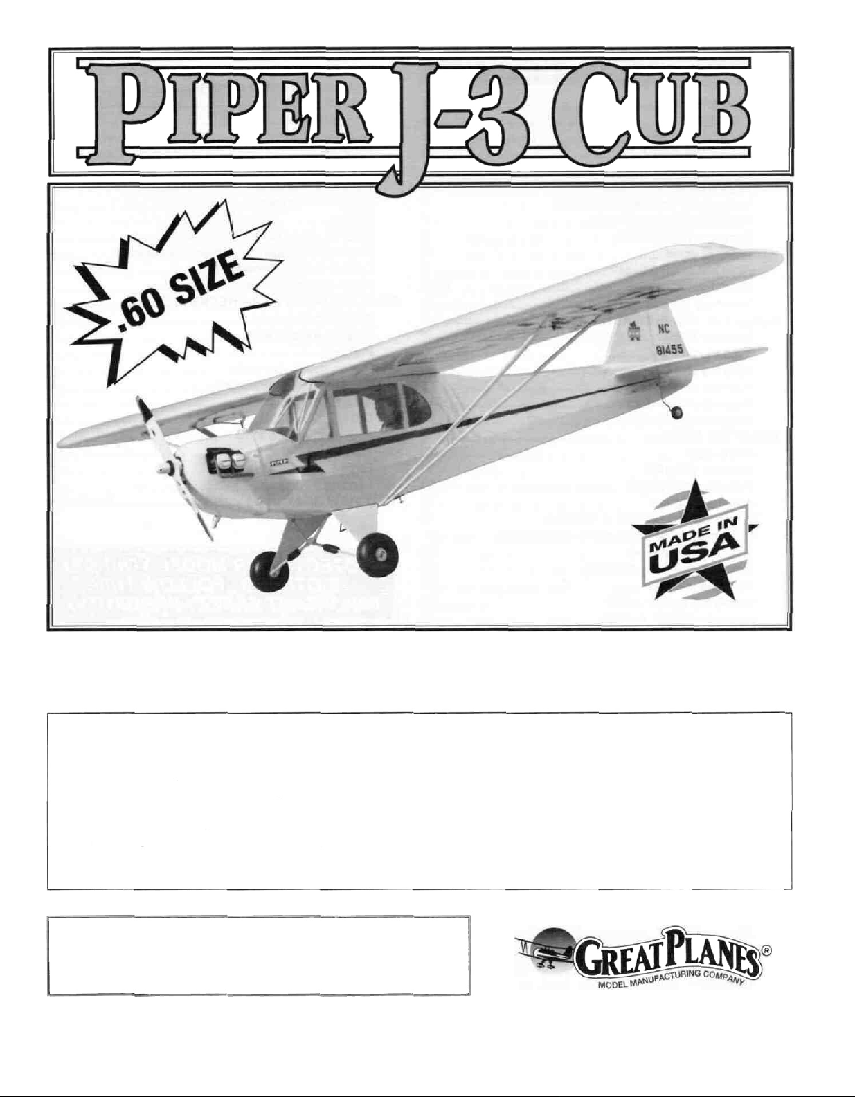
Congratulations! Thank you for purchasing the Great
Planes Piper J-3 CUB 60!
This J-3 CUB is a 1:4.7 scale model of the full-size version
It's easy to build and fly, predictable, fairly aerobatic, and
has no "bad habits" making it a great sport-scale airplane
Although the model is sufficiently close to scale that it can
place well in sport-scale competition, traditional Great
Planes quality and ruggedness is evident throughout,
making this an airplane you'll want to take along every time
you go to the flying field Its 90" wingspan makes it
International Miniature Aircraft Association* (IMAA) legal
(as is the 83" clipped wing version).
*IMAA is an organization that promotes non-competitive
flying of giant scale models.
IMAA
International Miniature Aircraft Association
205 S Hilldale Road
Salina, KS 67401
This is not a beginner's airplane! While the J-3 CUB is
easy to build and flies great we must discourage you from
selecting this kit as your first R/C airplane It lacks the
self-recovery characteristics of a good basic trainer such
as the Great Planes PT Series On the other hand if you
have already learned the basics of R/C flying and you are
able to safely handle a "trainer" airplane, the J-3 CUB is an
excellent choice to improve your skills and learn
new maneuvers
1 You must build the plane according to the plans and
instructions. Do not alter or modify the model, as doing so
may result in an unsafe or unflyable model In a few cases
the plans and instructions may differ slightly from the
photos In those instances you should assume the plans
and written instructions are correct.
2. You must take time to build straight, true and strong
3 You must use a proper R/C radio that is in first class
condition, the correct sized engine and correct
components (fuel tank, wheels, etc ) throughout your
building process.
4 You must properly install all R/C and other components so
that the model operates properly on the ground and in the air.
5 You must test the operation of the model before the first
and each successive flight to insure that all equipment is
operating and you must make certain that the model has
remained structurally sound Be sure to check the nylon
clevises often, and replace if they show signs of wear
6. You must fly the model only with the help of a
competent, experienced R/C pilot if you are not already
an experienced and knowledgeable R/C pilot at this time
NOTE We, as the kit manufacturer, can provide you with a
top quality kit and great instructions but ultimately the
quality of your finished model depends on how you build it,
therefore, we cannot in any way guarantee the
performance of your completed model, and no
representations are expressed or implied as to the
performance or safety of your completed model
Remember: Take your time and follow directions to
end up with a well-built model that is straight and true.
Please inspect all parts carefully before starting to
build! If any parts are missing, broken or defective, or if
you have any questions about building or flying this
model, please call us at (217) 398-8970 and we'll be
glad to help. If you are calling for replacement parts,
please look up the part numbers and the kit
identification number (stamped on the end of the
carton) and have them ready when calling.
3
Page 4
D Four-channel radio with 5 servos
D "Y" Harness (Futaba J HCAM2500, Airtronics
HCAM2520, JR HCAM2530)*
-orD Dual Servo Extension (Futaba J FUTM4130)
D 6" Servo extension cords (3) (Futaba J HCAM2000,
Airtronics HCAM2020, JR HCAM2030)
D Propellers (see engine instructions for
recommended size)
D 12 to 16 oz Fuel Tank (12 oz. GPMQ4105, 14 oz.
GPMQ4106, 16 oz GPMQ4107)
D 1-1/2" Tail Wheel (GPMQ4243)
D 4" Cub Wheels (GPMQ4230 3-3/8" Piper Cub
Wheels suitable)
D 3/16" Wheel Collars (4) (GPMQ4308, pkg of 4)
D 3/32' Wheel Collars (2) (GPMQ4302, pkg of 4)
D 3/16" Bolt on Axle Shafts (GPMQ4278)
D 25 foot roll model covering (Top Flite Cub Yellow
MonoKote Covering TOPQ1220)
D 1/8" black striping tape (GPMQ1480)
D Medium silicone Fuel Tubing (GPMQ4131)
D 1/2" thick Latex Foam Rubber Padding (HCAQ1050)
D Flexible Cable throttle pushrod (opt'l) (GPMQ3700)
D Screw-Lock Pushrod Connectors (opt'l) (GPMQ3870)
D Switch & Charge Jack Mount (optional) (GPMM1000)
D Fuel filter (optional) (GPMQ4150)
D Fueling Valve (GPMQ4160)
D Fuelproof paint (see "Painting" section of instructions
on page 44)
D 3" scale pilot (optional) - (Williams Bros. WBRQ2626)
*ltems in parenthesis (GPMQ4130) are suggested part
numbers recognized by distributors and hobby shops and
are listed for your convenience Our own brand has been
provided where possible GPM is the Great Planes brand,
HCA is the Hobbico brand, TOP is Top Flite
D 2 oz Thin CA Adhesive - (GPMR6015)
D 2 oz Medium CA Adhesive - (GPMR6009)
D 2 oz Thick CA Adhesive - (GPMR6003)
D CA accelerator (optional) - (HCAR3750)
D CA applicator tips (optional) - (HCAR3780)
D 6-Minute Epoxy - (GPMR6045)
D 30-Minute Epoxy - (GPMR6047)
D Pacer Z-560 (optional) - for gluing windscreen and
side windows (PAAR3300)
D Silver Solder (recommended) - (GPMR8070 w/flux)
D Hand or Electric Drill
D Drill Bits 1/16", 3/32", 7/64" or #35, 1/8", #29 or 9/64",
11/64", 3/16", #10 or 13/64", 7/32", 15/64", 17/64" and
1/4"
D Sealing Iron - (TOPR2100)
D Hot Sock (optional) - (TOPR2175)
D Heat Gun (optional) - (TOPR2000)
D Razor Saw
D #1 knife handle - (XACR4305)
D #11 Blades - (XACR3121 pkg of 5)
D Common pliers
D Screwdrivers (phillips and flat)
D T-Pins - (HCAR5100 small, HCAR5150 medium,
HCAR5200 large)
D Straightedge - (Fourmost Non Slip FORR2149)
D Masking Tape
D Sandpaper (coarse, medium, fine grit)
D T-Bar or sanding block
D Waxed Paper
D Lightweight Balsa Filler - (HCAR3401)
D 5/32" brass tube (optional)
D 1/8" brass tube (optional)
D Tap Wrench
D 1/4-20 Tap - (GPMR8105 w/dnll bit)
D 8-32 tap - (GPMR8103 w/dnll bit)
D 6-32 tap - (GPMR8102 w/dnll bit)
D IsopropyI Rubbing Alcohol (70%)
D Dremel Moto Tool or similar w/sanding drum, cutting
burr (optional)
D 9/64" ball end hex wrench - (GPMR8004)
D Kyosho" Curved Scissors (optional) - (KYOR1010)
4
Page 5
On our workbench, we have four 11" T-Bar sanders,
equipped with #50, #80, #150 and #220-grit sandpaper.
This setup is all that is required for almost any sanding
task. Custom sanding blocks can be made from balsa for
sanding hard to reach spots. We also keep some
#320-grit wet-or-dry sandpaper handy for finish sanding
before covering.
T-Bar sanding tools are made from lightweight
extruded aluminum and can be found at most hobby
shops. A 2" x 11" strip of sandpaper is attached to the
T-Bar by gluing it on with rubber cement. Apply the rubber
cement to both the bottom of the T-Bar and the back of
the sandpaper. When both surfaces are dry, press the
sandpaper firmly onto the T-Bar. Spray adhesive can be
used for this purpose but it's harder to remove the
sandpaper when you need to replace it.
Wooden sanding blocks can be made from 11" lengths of
1" x 2" scrap lumber. Start on one side, then wrap a sheet
of sandpaper completely around the wood, ending on the
same side as the one you started on. Push 3 or 4
thumbtacks into this edge, then trim off the excess material.
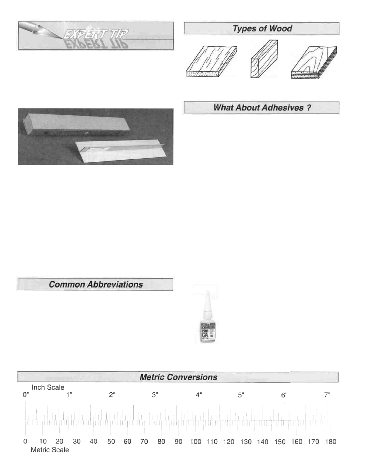
Balsa Basswood Plywood
We understand that the caliber of modelers likely to build
the Great Planes Cub 60 may be rather high. You may
already know all about the types of adhesives you like to
use. However, due to its stability and easy building
features, many first time or second time builders may try
their hand at the Great Planes Cub 60. For those modelers
(experts may read along), we have provided some
explanation about the variety of adhesives used during
construction of a model.
Cyanoacrylate or CA glue has changed the way models
are built more than any other advance in modeling
technology. In the good ol' days, model cement like
Ambroid, Duco, Comet and Sigment were the glues of
choice. They all had a strong odor that could cause
dizziness, dried slowly (compared to CA) and became
brittle with age. CA, on the other hand, is stronger, works
almost instantly and is bottled in three different viscosities
(thicknesses). CA is used for most glue joints, except where
epoxy is specified. CA does emit rather strong fumes (some
say it's like tear gas) as it cures, so rule number one is to
work in a well ventilated area. All CA glues work best if
the joints are smooth and fit well.
Elev = Elevator
Fuse = Fuselage
LE = Leading Edge (front)
LG = Landing Gear
Lt = Left
Ply = Plywood
Rt = Right
Stab = Stabilizer
TE = Trailing Edge (rear)
" = Inches
Thin CA is also known simply as CA. This
is the adhesive that has revolutionized
model building because it allows you to
assemble the parts first, then apply the
adhesive. The thin formulation flows or
"wicks" into the joints and sets almost
instantly, eliminating the need to hold
things together while the glue dries. You
will often use Thin CA for the initial bond, then follow with
medium or thick CA for extra strength, especially when gluing
plywood or hardwood. (Continued on page 8)
5
Page 6
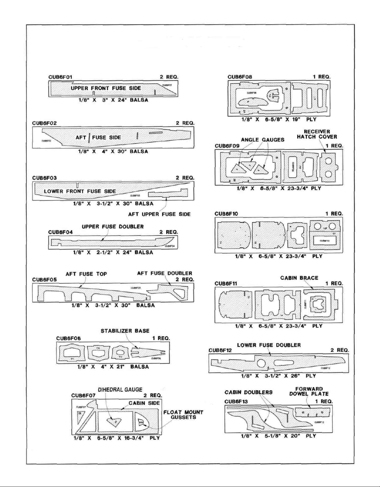
DIE-CUT PATTERNS
6
Page 7
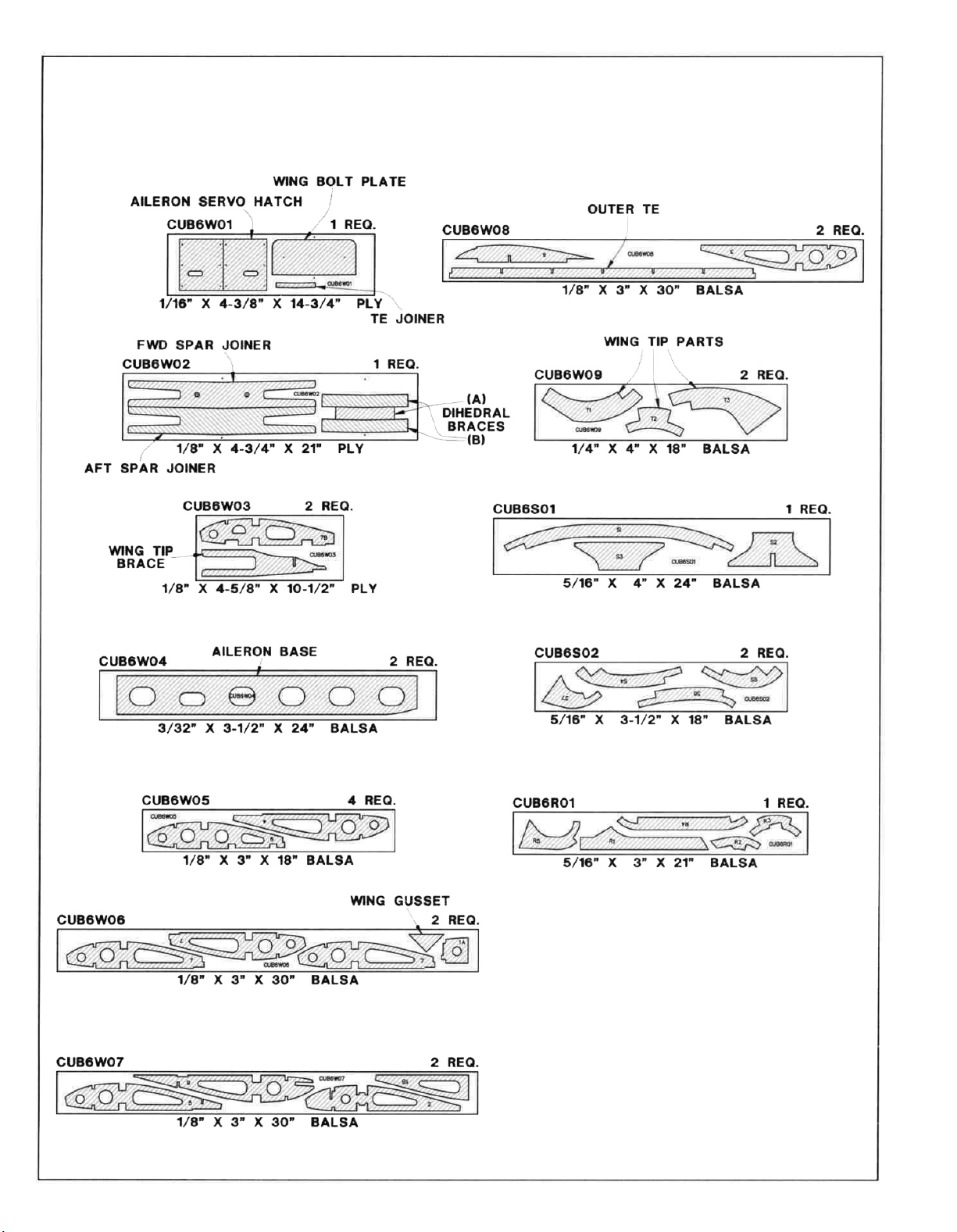
DIE-CUT PATTERNS
7
Page 8
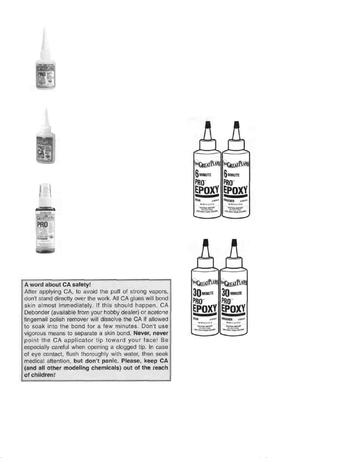
CA+ is also known as medium or gap
filling CA CA+ is used for surface
gluing, filling small gaps between poorly
matched parts and for general purpose
applications It cures slower than thin CA,
allowing you to apply a bead to two or
three parts before assembly Curing time
without accelerator is 20-30 seconds
CA- or thick CA is used when extra
positioning time is needed CA- is a great
gap filler and is also used to make fillets
when a little extra strength is required.
Curing time is about 1-2 minutes.
Accelerator is a liquid chemical that
comes in a spray bottle for use in
speeding up the cure time of all CA
types It should be misted on, not
sprayed heavily on the joint Accelerator
may cause exposed CA to bubble and
sometimes change color. If accelerator
is sprayed on too heavily it may weaken
the glue joint, so use it sparingly
hold-down blocks As with most epoxies you mix equal
parts of resin and hardener, stir well, then apply a thin film
to each part Parts should be clamped, pinned, taped or
weighted in place until fully cured Before the epoxy cures,
clean off any excess with a paper towel A word of caution
about mixing epoxy-don't use extra hardener in the
hopes of making the mixture harder or work faster Just
about all epoxies work best with exactly a 50/50 mix When
you increase the amount of hardener you run the risk of
causing the cured epoxy to become either brittle or
rubbery-neither being as strong as a properly mixed batch.
6-Minute epoxy is used
for simple, small gluing
applications-where
elaborate alignment is not
equired Working time
(before it's too gooey to
use) is about 5 minutes,
handling time 15 minutes
and it's fully cured in about
1 hour.
Epoxy
Great Planes has two epoxy formulations available for the
modeler Both offer exceptional strength and convenient
working times Use epoxy when the joint requires
exceptional strength, such as when installing the firewall,
when joining the wing panels, and when installing wing
30-minute epoxy is used
for extra strength (because
it can penetrate longer) and
where several parts must
e aligned and checked
before it cures Working
time is about 25 minutes,
handling time 2 hours, and
it's fully cured in 8 hours
Great Planes Pro" Wood Glue is an Aliphatic resin glue
that works well on all types
odorless and dries clear Some people are sensitive to CA
and epoxy fumes, so this is a good alternative for general
modeling use Its only drawback is that it is slow to cure,
requiring the parts to be securely clamped, pinned or taped
while the glue dries
Okay, you've got your work space ready your tools are at
hand, and you know how to choose and use the right glue
for the job Let's get started!
of
wood
It
is
non-toxic, virtually
8
Page 9
D 1 Unroll the plan sheets Reroll the plan inside out to
make them lie flat
MARK
CENTERLINES
Before beginning construction of each individual tail
surface tape waxed paper over the drawing when it is
time to build that piece Begin with the rudder
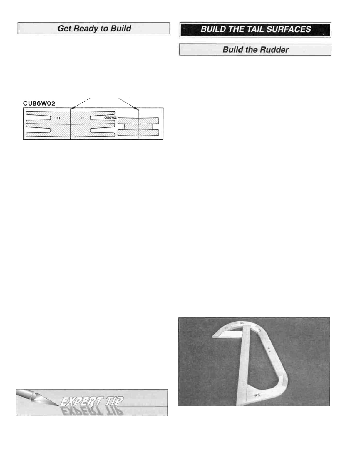
D 1 Place the die-cut 5/16" balsa rudder parts R2, R3,
R4 and R5 over the plan in their locations Check each
joint for a good fit and make adjustments if necessary Pin
the parts to the building board but do not use glue at
this time.
D 2 Locate the die-cut 1/16" plywood sheet W01 and the
die-cut 1/8" plywood sheet W02 Draw centerlines on the
dihedral braces, wing joiners and wing bolt plate by
connecting the punch marks.
D 3 Remove all parts from the box As you do, determine
the name of each part by comparing it with the plan and
the parts list included with this kit Using a ball point pen,
lightly write the part name or size on each piece to avoid
confusion later Use the die-cut patterns shown on pages 7
and 8 to identify the die-cut parts and mark them before
removing them from the sheet Save all scraps If any of
the die-cut parts are difficult to punch out do not force
them' Instead, cut around the parts with a hobby knife
After punching out the die-cut parts, use your T-Bar sander
or sanding block to lightly sand the edges to remove any
die-cutting irregularities
D 4 As you identify and mark the parts, separate them
into groups, such as fuse (fuselage), wing, fin, stab
(stabilizer) and hardware.
NOTE: The purpose for checking each joint for a good fit is
to be sure the finished shape of the assembly matches
that of the drawing on the plan Every joint may not be an
exact fit due to the technical nature of die-cutting such thick
wood (5/16") If you're a very discriminating builder, you are
likely to spend a few extra moments perfecting the fit of
each and every joint before reaching for the CA Simply
filling in the small gap where noticeable with thick CA is an
alternate method to custom fitting each part and will yield a
secure, strong glue joint
D 2 Select the straightest piece of 5/16" x 7/8" x 24" balsa
stick Set this piece aside for use later on the stabilizer
trailing edge
D 3 Cut the rudder leading edge from another 5/16" x
7/8" x 24" balsa stick Check for a good fit, then pin the LE
to the building board over its location Cut the horizontal
frame section from the remaining piece of balsa and pin
into position
Zipper-top food storage bags are handy to store your
parts as you sort, identify and separate them into
sub-assemblies
D 4 Remove the parts from the plan, then one at a time,
pin each piece back into position using thick CA to
securely glue the parts together Wipe away excess glue
with a paper towel before it cures - sanding will be
easier later
9
Page 10
D 5 Cut the ribs from the 5/16" x 5/16" x 30" balsa stick.
Position the ribs in the rudder frame and securely glue
them in place with thick CA.
D 6 Remove the rudder from the building board and
inspect all the glue joints Add thin CA to all the tight-fitting
joints and thick CA to any open joints Large gaps may be
filled with balsa dust and thin CA.
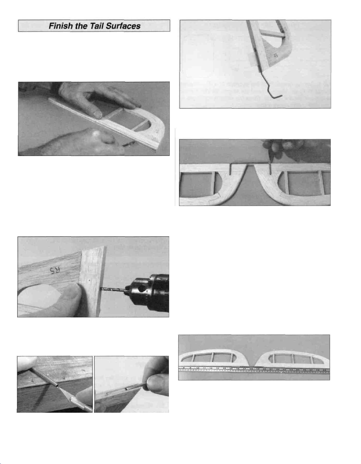
D 1. Securely glue the die-cut 5/16" balsa stabilizer parts
S2 and S3 together over the plan.
D 2 Position S1 and the two S4's over their locations on
the plan Check the fit of the joints, make adjustments if
necessary, then pin them in place.
D 3. Cut the stabilizer trailing edge from a 5/16" x 7/8"
balsa stick. Fit the trailing edge between the S4's.
D 4 When satisfied with all joints, remove the assembly
from the building board Reinstall each part on the building
board with pins, gluing them together with thick CA as you
proceed.
D 5. Cut the ribs from the 5/16" x 5/16" x 24" balsa stick
and glue them in place with thick CA.
D 1. Locate the die-cut 5/16" balsa fin leading edge R1
and pin it in place on the plan.
D 2. Cut the fin top, fin base, and the inner and outer fin
trailing edges from the remaining 5/16" x 7/8" balsa strip
Pin the parts in place and make sure all the joints fit well.
Remove the parts and securely glue each joint with thick
CA as you pin them back into position.
D 6 Remove the stabilizer from the building board and
inspect all the glue joints. Apply thick or thin CA where
necessary.
D D 1. Pin the die-cut 5/16" balsa elevator parts S5, S6
and S7 on the plan, making adjustments for any poor-fitting
glue joints.
D D 2 Cut the elevator leading edge from a 5/16" x 7/8"
balsa strip Fit the LE in place on the plan and pin it in
place Glue all of the joints with thick CA, in the same
manner as described previously.
D 3 Cut the ribs from the remaining 5/16" x 5/16" balsa
stick. Glue them in place with thick CA.
D 4. Remove the Fin from the building board and inspect
all the glue joints Apply thick or thin CA where necessary.
D D 3. Cut the elevator ribs from the 5/16" x 5/16" balsa
stick and glue in position with thick CA.
D D 4. Remove the elevator from the building board and
inspect all the glue joints. Add CA where necessary Build
the other elevator.
10
Page 11
D 1. Carefully sand all the tail surfaces flat with 150-grit
sandpaper and a large sanding block or T-bar. Remove as
little material as possible and don't get carried
away - inspect your work as you proceed. It's easy to
sand a low spot into the ribs or trailing edges.
D 2. Centerlines must be drawn where the hinges are to
be inserted. Start with an elevator. A Bic ball point pen lines
up with the center of the 5/16" thick balsa (double check
this - the height may vary due to the extent of your sanding
or different pens. Adjust the height of the pen or the
elevator as necessary to draw a centered line). Lay the
elevator and the pen on a flat table and draw a line on the
edge. Draw centerlines on the leading edges of the rudder
and elevators, and on the trailing edges of the stabilizer
and
fin.
D 5. Trial fit the tail gear wire in the rudder. Make
adjustments if necessary.
D 6. Position the elevators on the plan and center the
elevator joiner wire over the elevators. Transfer the
location of the joiner wire to the elevators. Make the marks
lightly so they may be sanded off easily.
D 3. From the bottom of the rudder measure 1-5/8" along
the leading edge. Then drill a 7/64" hole, 3/4" deep, where
the tail wheel wire fits into the rudder.
D 4. Groove the rudder to clear the hinge bearing. A
sharpened piece of 5/32" brass tubing works well as a tool
to cut the groove.
D 7. Accurately drill a 9/64" (or #29) hole into each
elevator leading edge approximately 1" deep. The hole
must be perpendicular to the elevator leading edge.
0 8. Cut a groove in the leading edge of the elevators to
accept the elevator joiner wire. A sharpened piece of 1/8"
brass tube works well to cut the groove just as you did
the rudder.
D 9. Test fit (do not glue yet) the joiner in the elevators.
With the joiner inserted, the elevators must lie flat and the
leading edges must line up with a straightedge. If the
elevators both don't lie flat on a table top, you may make
slight adjustments by carefully twisting the joiner wire. If the
leading edges don't match up with a straight edge, you
may slightly enlarge the holes drilled into the elevator
leading edges to allow slight repositioning.
11
Page 12
D 1 Cut the hinges from the supplied 2" x 9" composite
hinge material You will need six hinges for the elevator
and three for the rudder Store the remaining hinges for
use later during construction.
D 2 Use the plan as a guide to lightly mark the locations
of the hinges Refer to the Expert Tip that follows, then cut
matching hinge slots in all four parts.
Expert tip for using CA hinges
The hinge material supplied in this kit consists of a
3-layer lamination of mylar and polyester It is specially
made for the purpose of hinging model airplane control
surfaces Properly installed, this type of hinge provides
the best combination of strength, durability and ease of
installation We trust even our best show models to these
hinges, but it is essential to install them correctly
Please follow the instructions carefully to obtain the best
results These instructions may be used to effectively
install any of the various brands of CA hinges.
the slot If the hinge does not slide in easily, work the
knife blade back and forth in the slot a few times to
provide more clearance (it is really the back edge of the
blade that does the work here in widening the slot).
B Drill a 3/32" hole, 1/2" deep, in the center of the
hinge slot. If you use a Dremel Moto-TooF for this task,
it will result in a cleaner hole than if you use a slower
speed power or hand drill Drilling the hole will twist
some of the wood fibers into the slot, making it difficult to
insert the hinge so you should reinsert the knife blade,
working it back and forth a few times to clean out the
slot.
C Trial fit the hinges into the slots and, without using
any glue, temporarily attach the control surface, to verify
the
fit.
STOP! DO NOT GLUE THE HINGES IN PLACE UNTIL
AFTER THE MODEL IS COVERED!
The most common mistake made by modelers when
permanently installing this type of hinge is not applying a
sufficient amount of glue to fully secure the hinge over its
entire surface area, or, the hinge slots are very tight,
restricting the flow of CA to the back of the hinges This
results in hinges that are only "tack glued" approximately
1/8" to 1/4" into the hinge slots The following technique
has been developed to help ensure thorough and
secure gluing.
A. Cut the hinge slot using a #11 blade in a standard #1
knife handle The CA hinges provided have a thickness
that fits this type of slot very well Trial fit the hinge into
D 3 Bevel the leading edges of the elevator and rudder
Draw the "bevel to" lines on the leading edges of the
elevators and the rudder Refer to the plan for the
correct angle.
D 4. Carve or sand the bevel on the leading edges of the
rudder and elevators A razor plane allows you to rough-in
the bevel before finishing with a sanding block
D 5 Reinstall the hinges and test fit the operation of the
rudder and the elevators Make adjustments in the hinge
slots if necessary Now would be a good time to designate
a top and bottom of the elevators and stabilizer - just in
case one side looks a little better than the other
12
Page 13
D 6 Sand the leading edges of the stabilizer, fin and the
trailing edges of the rudder and elevators to a rounded
shape, as shown in the cross-sections on the plan.
D 7. Sand the elevator joiner with 150-grit sandpaper for
good glue adhesion then liberally pack the holes in the
elevators with 30-minute epoxy Insert the joiner and wipe
away epoxy before it cures.
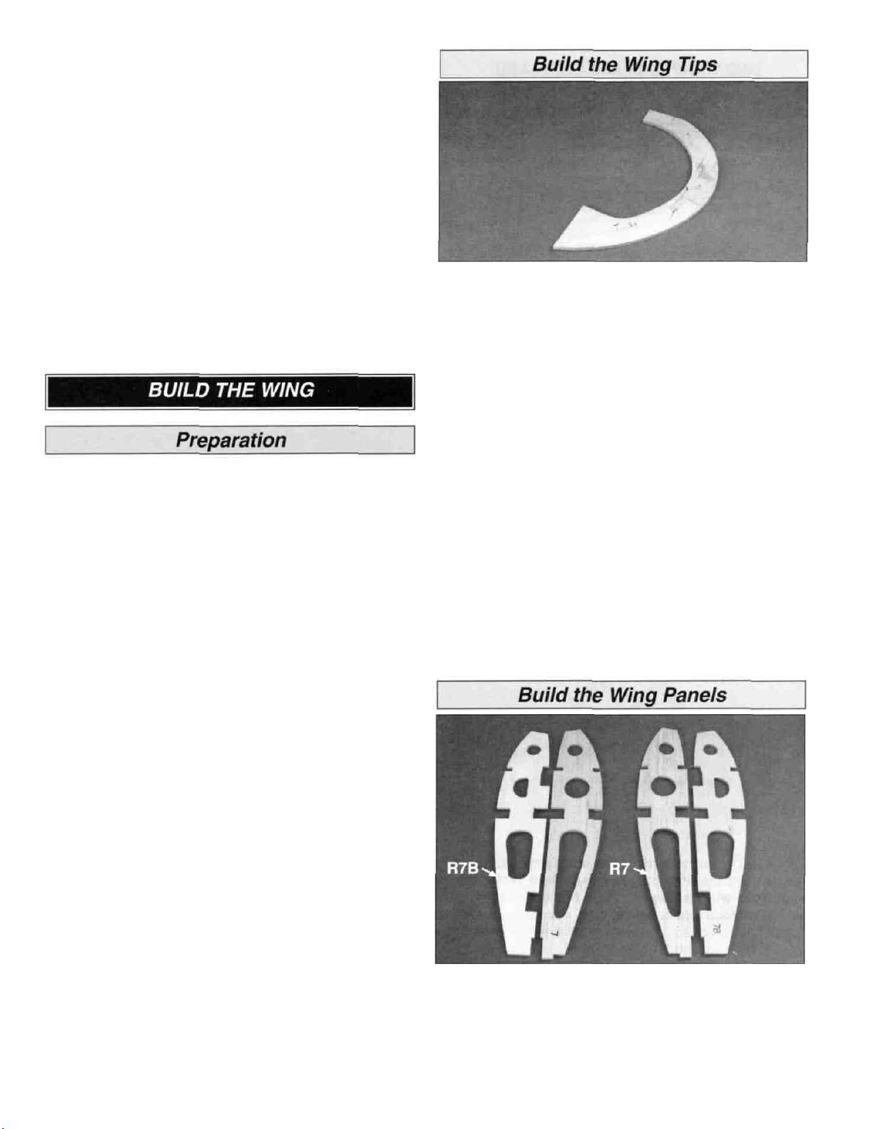
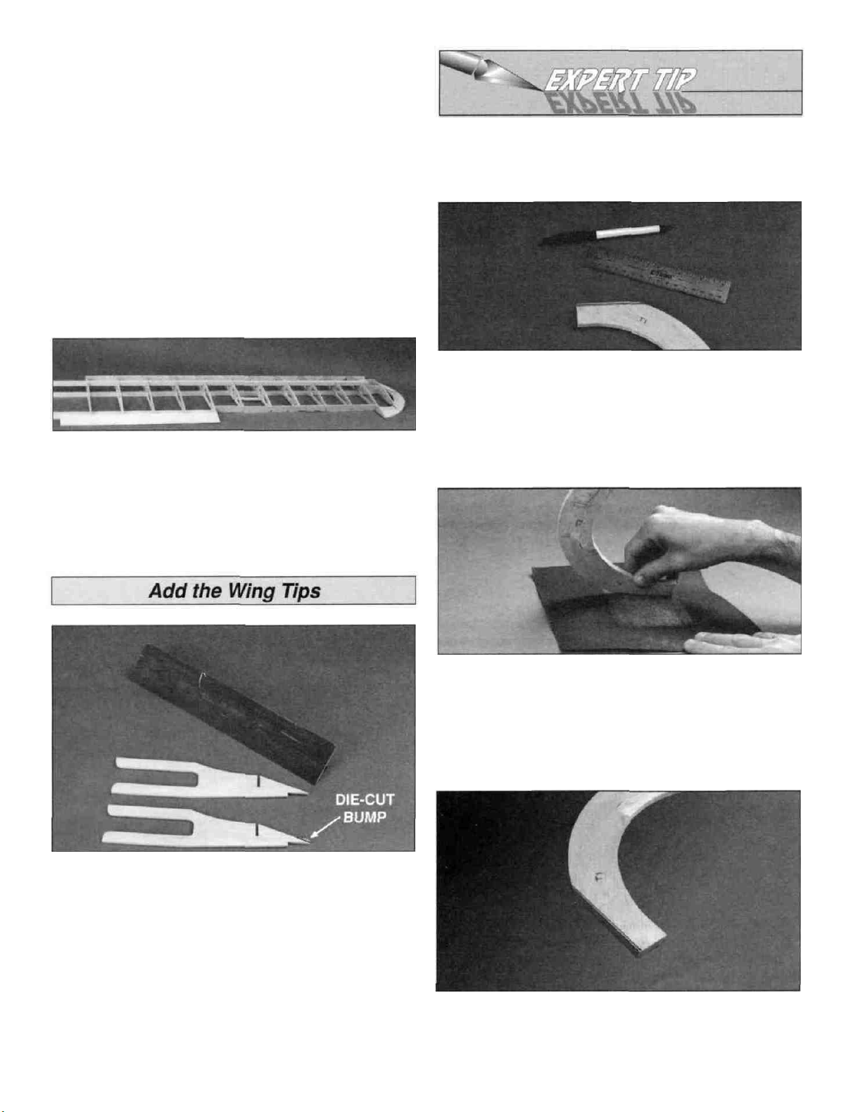
D D 1. Place the die-cut 1/4" balsa wing tip parts T1, T2
and T3 over the plan and check all joints for proper fit.
Make adjustments if necessary Pin the parts over the
plan, gluing with thick CA as you proceed.
D D 2 Remove the wing tip from the building board and
inspect all the glue joints Add thin CA to all tight joints and
thick CA to all open joints.
IMPORTANT: For an airplane to fly well with no
unexpected tendencies, all good modelers understand that
each assembly - especially the wing - must be built on a
flat surface This is important advice for new builders Also,
a relatively soft, flat building board that you can stick "T"
pins into is required. This is for pinning down individual
parts that make up the completed assembly A suitable
building board is a sheet of ceiling tile or "Celotex" used in
home construction This material may be found at
hardware or home improvement stores. If the building
board is not flat, it must be clamped to your flat building
table. Now we're ready to begin!
NOTE: The plan shows the two different wing types
which may be built from this kit. You may choose the
standard wing or the clipped wing version Generally, the
clipped wing will be more aerobatic than the standard wing
If you decide to build the clipped wing, cut the plan on the
dashed line between the two R4 ribs Overlap the plan
towards the center of the wing and match the registration
marks as indicated. Keep the plan straight, then tape it
together when you have the registration marks aligned
Check the alignment with a straightedge. No change is
necessary for the standard wing.
D D 3 Place the wing tip on your work surface and lightly
sand both sides flat and smooth with a sanding block and
150-grit sandpaper.
D 4. Return to step 1 and build the other wing tip.
NOTE: One R4 rib is eliminated from each wing panel if
building the clipped wing.
Build one wing "half or panel at a time. You may cut each
wing panel from the plan sheet to place on your building
board. Tape the right wing plan to your flat work surface,
and cover it with waxed paper.
D 1 Carefully punch out all the die-cut 1/8" balsa R2
through R8 wing ribs and the die-cut 1/8" plywood rib
doublers R7B Sand the edges slightly to remove any
die-cutting irregularities. Use thick CA to laminate the
R7Bs to ribs R7. Don't forget to make a RIGHT and
a LEFT.
13
Page 14
TWO WARPED SPARS INSTALLED
THIS WAY WILL RESULT IN A
STRAIGHT WING
TWO WARPED SPARS INSTALLED
THIS WAY WILL RESULT IN A
WARPED WING
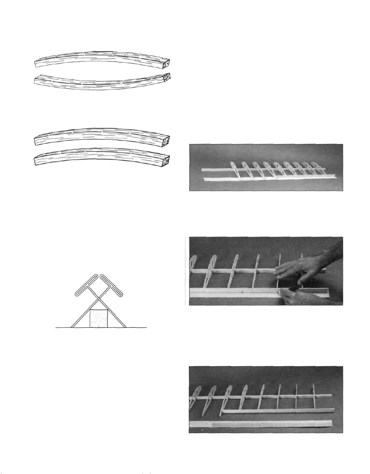
D D 2 Locate all four 1/2" x 1/2" x 40" basswood spars.
Examine them carefully for possible imperfections Look for
knots, soft spots, diagonal grain and any other
imperfections If possible, position each spar so the
imperfections are on the outer half of the wing panel
(toward the tip) where they will be least affected by high
stress If the spars are warped slightly, try to "balance them
out by installing the warped spars in opposite directions
(see sketch).
D D 5. Without gluing, place ribs R3 through R7 and the
laminated R7/R7B (but not R2 or R8) on the spar in their
locations as shown on the plan If building the clipped wing
version, discard one of the R4 ribs.
NOTE: Rib 3 does not contact the plan since the center
section will be sheeted later.
D D 6 Slide the trailing edge sheet against the notches in
the bottom of the ribs The outer tip of the sheet should
match the plan and the "overhang" should be at the
center section.
D D 7 Position the die-cut 1/8" balsa outer trailing edge
at the rear of ribs R5 through R7.
D D 3. Do not use any glue until step 15. For now,
we're just making preparations and familiarizing
ourselves with the layout Place one of the 1/2" x 1/2" x
40" basswood spars on the wing plan and pin the spar
down with crossed T-pins as shown in the sketch We
recommend crossed T-pins at every rib bay (the space
between the ribs) NOTE: Align the end of the spar with the
outboard edge of wing rib R8 at the wing tip.
D D 4. Locate a 3/32" x 2" x 40" balsa trailing edge
sheet. It is supplied slightly wide so you may trim it to
straighten any bowed edges Using a straightedge, trim the
piece to 1-29/32". Set the trailing edge sheet aside for now.
D D 8 Mark a line on the trailing edge sheet against the
entire length of the outside of the outer trailing edge and rib
R5 As you mark the line, make sure all ribs and the outer
trailing edge are lying flat on the sheet.
D D 9. Remove the sheet and use a straightedge and
knife to cut along the line. Save the scrap piece.
14
Page 15
D D 10 Slide the finished trailing edge sheet into
position. Don't reach for the glue yet Add rib R8.
D D 14 Match the notches in the 42" shaped balsa
leading edge with the plan Add the leading edge to the
ribs (still no glue) making sure each rib is fitted into its
respective notch Center the leading edge so there is an
equal amount of space above and below each rib Cut the
leading edge flush with rib R2.
D D 11 Locate the tapered balsa inner trailing edge If
you are building the clipped wing version, be sure the
rib notches line up with the rib locations on the plan
before cutting. Pin the inner trailing edge in position with
the ribs in the notches, then cut the outboard tip of the
inner trailing edge flush with the outboard edge of rib R5.
D D 12. Fit the ribs into the notches on the inner trailing
edge, then push it as far forward as it will go until the ribs
are fully seated Pull the sheet back until it is tight against
the trailing edge Pin the inner trailing edge and the trailing
edge sheet to the plan Install rib R2.
NOTE: Rib 2 will not contact the plan since the center
section will be sheeted later.
Double check your work Make sure all ribs are
contacting the trailing edge sheet and fit all the way
onto the basswood spar. Confirm that each rib meets the
spar exactly at its intended location over the plan After all
the fitting and Jiggling of parts, now is the time to be sure
the spar is still securely pinned to your flat building board.
Repin or add more pins if necessary
Let's start gluing!
D D 13 Cut the 1/4" x 1/2" x 18" balsa aileron servo rail
stick into four pieces, 3-3/4" each Remove both R6 ribs
Install both servo rails Refer to the cross-section
drawing - be sure both servo rails are fully seated into their
notches The ends of the servo rails must be flush with the
ribs Reinstall the assembly over the spar and into the outer
trailing edge (I promise we'll be gluing soon).
D D 15 Beginning with rib R3, use the die-cut 1/8"
plywood 90 degree triangle (indicated as "90") to make
sure the rib is vertical while you add a few drops of thin CA
where the rib meets the spar Don't glue rib R2 to the
spar until instructed to do so. Be sure the bottom rear of
each rib is contacting the trailing edge sheet Don't add too
much CA - we're just "tack gluing" now Add a few drops of
CA to R2 where it contacts the trailing edge sheet Glue the
remaining ribs to the spar and trailing edge sheet (don't
glue R2 to the main spar) making sure each rib is
vertical and contacting the trailing edge sheeting.
15
Page 16
D D 16. Wick thin CA along the joint where the outer
trailing edge contacts the sheet and also to each rib. Glue
both servo rails to the R6 ribs and glue the aft servo rail to
the sheeting. Wick thin CA into the notches in the inner
trailing edge at each rib and glue the inner trailing edge to
the trailing edge sheet.
D D 17. Confirm that the leading edge is still centered
and each rib is tightly fitted into the notches. Refer to the
sketch at step 14 to see how the leading edge matches the
ribs; the leading edge is tilted downward somewhat. Wick
thin CA into each joint.
D D 18. Install the top 1/2" x 1/2" x 40" basswood spar.
Confirm that the top of the spar is flush with the top of each
rib and make sure the ribs are vertical (90°). The outer tip
of the spar should be flush with rib R8, just like the bottom
spar. Glue the spar in place with thin CA.
HOW TO MAKE A BEVEL
The following process will help you create a bevel that is
right the first time.
A) First, you need a fresh, full sheet of 220-grit
sandpaper. Draw the bevel lines and reference lines on
the part. The bevel lines are the lines that you sand to.
The reference lines are lines slightly over the size of the
bevel that you use as a reference in order to keep the
bevel parallel.
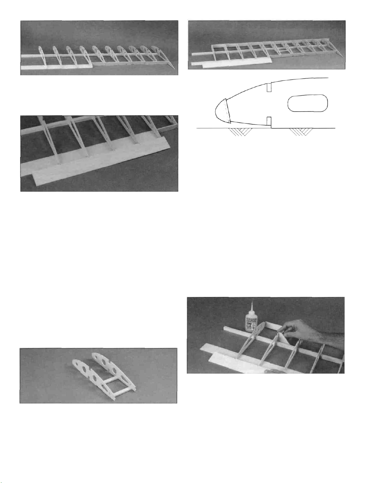
D D 1. Locate the die-cut 1/8" plywood wing tip brace,
the die-cut 1/8" balsa wing tip rib R9 and your previously
assembled outer wing tip. Sand off the "die-cut bump" from
the wing tip brace.
D D 2. Fit the wing tip rib R9 into the plywood wing tip
brace and slide the assembly into the ribs along the spars.
Slide the previously prepared outer wing tip into position.
Refer to the following Expert Tip to bevel the leading edge
of the wing tip.
B) Sand to the bevel lines. The method of sanding is
important. Sand only in one direction - usually "dragging"
the part is best as it keeps it from "chattering" and
creating the unwanted rounded bevel. It helps to imagine
the angle of the bevel required as you begin to sand. Just
take a little off at a time and mind your border lines.
C) After careful sanding and frequently inspecting your
work as you go, you will have a sharp, accurate bevel.
The bevel is parallel to the reference lines.
16
Page 17

D D 3. Install only the tip brace and glue it to the spars
Hint: apply thick CA to the spars first, then slide the tip
brace into place. Install rib R9 but don't glue it yet.
NOTE: At this point the wing should still be pinned to the
work surface Of course, we cannot add shear webs if the
crossed T-pins are in position, so just take out the T-pins as
you go Replace the T-pins through the shear webs in
order to keep the wing flat on your building board - or, use
weights on top of the wing instead of the T-pins to hold the
wing flat as you glue the shear webs in position. You only
need to replace T pins at every other rib bay
D D 2 Install three shear webs in front of the spars
between ribs R3-R4, R4-R4 and R4-R5 If building the
clipped wing version, only two front shear webs are
required between ribs R3-R4 and R4-R5.
D D 3 Locate the 3/16" x 1/4" x 40" basswood top
forward spar Before gluing it into position, cut off two
1" pieces to be used later Glue the spar in the forward rib
notches The "overhang is at the root end past rib R2, and
the tip of the spar should be flush with rib R8.
D D 4 Install the tip and glue it at the leading edge first,
then glue it to the rib R8 Let the tip take its natural
position - slightly slanting upward towards the leading
edge. Glue tip rib R9 to complete the wing tip assembly.
Proceed with wing panel construction
D D 1 Glue eight (seven for the clipped wing) 1/8" x
3-1/2" x 1-3/4" pre cut balsa vertical grain aft shear webs
to the rear of the basswood spars, starting between ribs R3
& R4 and ending between the last R7 ribs No shear webs
are installed between R2 & R3 and the last R7 & R8 ribs at
this time. The shear webs are provided slightly "not tall
enough" so they may be positioned without protruding
above or below the top and bottom spars It's not
necessary to glue the shear webs to the ribs - but it is
important to glue the shear webs securely to the spars
D D 4 Cut eight 3/8" x 5/8" x 1-3/4" hinge blocks from
the 3/8" x 5/8" x 15" balsa stick Position four hinge blocks
against the outboard trailing edge on the bottom trailing
edge sheeting Glue the blocks with thick CA. Refer to the
other wing plan for the exact position of the hinge blocks.
Save the remaining four hinge blocks for the other
wing panel
D D 5 Glue the die-cut 1/8" balsa wing gusset centered
vertically on the rib at the corner of rib R5 and the notched
inboard trailing edge.
17
Page 18

D D 6. Temporarily remove the wing from your building
board. Glue the 3/16" x 1/4" x 40" basswood bottom
forward spar in the notches in the ribs. There is no need
to need to remove the 2" from this spar.
Replace the wing on the flat building surface and pin it to
the board.
D D 7. Mark the center of the 3/8" x 3/4" x 3/4" basswood
wing strut blocks. Drill a hole in the center of each block
with a 1/8" drill bit. Glue the block to ribs R7 & R7B where
shown on the plan, with the grain running parallel with the
spars.
D D 9. Add ten (nine for the clipped wing version) 3/32" x
3-1/2" x 1-9/16" pre-cut vertical grain balsa forward shear
webs to the rear of the forward spars between each rib
bay. The shear web between R7/R7B and R7 will have to
be shortened to clear the strut block.
D D 10. Locate the die-cut 1/8" plywood dihedral gauge.
Hold the gauge next to the main spar with the corner of the
gauge at the dashed centerline on the plan. Mark both
sides of the main spar along the front edge of the gauge.
D D 8. Cut the 2" piece of the basswood top forward spar
from step 3 into two 1" long pieces. Use 30-minute epoxy
to glue the strut blocks into position with the grain direction
parallel with the spars. A 1" basswood "gusset" is also
glued to the side of the rib doubler R7B and to the top of
each block.
DD 11. Connect both lines by drawing a line across the
top of each spar.
D D 12. Follow the same procedure as steps 10 and 11
to mark the forward spars.
D D 13. With the wing panel still pinned to the plan,
transfer the wing's centerline from the plan onto the bottom
sheet and the notched trailing edge.
18
Page 19

D D 14. Accurately cut both front spars, both main spars,
the balsa bottom sheet and trailing edge.
D D 15. From the excess 1/2" x 1/2" main spar, cut off a
1" piece to be used later for the receiver hatch block.
D D 1. Use a T-bar sander or flat sanding block with 150grit sandpaper to carefully sand the top edges of the ribs to
smoothly blend them to the main spar. Remove any glue
bumps or other irregularities.
D D 3. Replace the sheet on the wing and mark the rear
edge of the sheet so it ends about 1/16" ahead of the aft
edge of the forward spar. Trim the rear of the sheet to
this mark.
D D 4. Before attempting to bend the sheet so it may
reach the outer wing tip, the sheet must be thoroughly
wetted from R8 outward. Use a spray bottle or a sponge
to liberally apply water to the tip area of the sheet outboard
of rib R8. Some experienced modelers add alcohol or
ammonia to the water in order to help penetrate the wood
fibers. About a 50/50
the sheet with your fingers by bending and twisting it in the
direction required to meet the wing tip. Replace the sheet
on the wing and test bending the sheet into position. Don't
force the sheet - add more water if necessary.
D D 5. When you position the sheet on the wing and
attempt to bend it down toward the wing tip, you will notice
that as the sheet bends, it also naturally twists rearward.
However, in this area the sheet is supposed to maintain a
straight line parallel to the spar. Trim a "curved wedge"
from the sheet starting at rib R8. Trim and test fit the sheet
until it conforms to the desired straight line.
mix
will
do the job.
Carefully
"work"
D D 2. Custom fit a 3/32" x 2-3/4" x 42" balsa wing LE
sheet. Use a straightedge to true the front edge of the
sheet and cut a slight bevel to match the angle of the
slanted leading edge.
OUTER WING TIP
D D 6. To provide gluing surfaces for the sheeting, carve
a bevel on both sides of the tip where the top and bottom
sheet will join the tip.
19
Page 20

D D 7. Position the leading edge sheeting against the
leading edge. Using thin CA, glue the front edge of the
sheet to the leading edge. Do not glue the sheet to the
leading edge past the last rib R8.
D D 8. Slightly wet the entire sheet to bend it to the spar.
D D 11. Because the sheet tends to bow upwards
between tip rib R8 and the outer tip, it may not be
contacting the tip rib R9. Don't necessarily glue the sheet
all the way down to the last tip rib R9. Instead, pull the
sheet to a position on the rib that will help distribute the
bowing upward effect of the sheet. Add a fillet of thick CA
to rib R9 while holding the sheet in the position desired.
We'll perfect the top sheeting of the wing tip later.
D D 12. Fill the small seam between the leading edge
and the front of the sheet between ribs R8 and R9 with a
scrap piece of balsa.
D D 9. Apply a generous bead of thick CA to the forward
spar. Working quickly, bend the sheeting to the spar,
holding it down with something flat like a T-bar sander or
flat block of wood until the glue cures. Remove the wing
from the building board.
D D 10. Wet the sheet one more time in the tip
area - the water may have evaporated from the balsa. Test
bend the sheet to the tip. Make last minute adjustments if
necessary. Apply thick CA where the sheet will contact the
outer tip, but don't add CA to the last tip rib R9 at this
time. Bend the sheeting to the outer tip rib and firmly hold
it in position until the CA cures.
D D 13. Glue the ribs to the sheet with thin CA. Inspect all
glue joints and add CA where necessary.
D D 14. Remove the extra sheeting from the end of the
wing tip.
D D 15. Install the 3/32" x 2-3/4" x 42" bottom leading edge
sheet almost the same way you installed the top - this time
apply thick CA to the ribs before you add the sheet.
20
Page 21

D D 16 Trim the excess bottom sheet and blend the
leading edge to the wing tip. Refer to the plan for the
correct shape.
D D 17 Back to the top sheet for a moment If the sheet
still bows upward too much between rib R8 and tip rib R9,
wet the balsa in this area and pull it down with masking tape
until all the water has evaporated from the wood Nearly all
the excess bow will be eliminated The rest can be sanded
out.
D D 3 From the 1/32" x 1/4" x 16" aileron servo hatch
shim, cut two strips to fit on top of the servo rails between
the 1/4" square stiffeners Using medium CA, glue the shims
into position flush with the inner edges of the servo rails (See
photo at Step 5 below.)
D D 4. Position the hatch. The rear edge of the hatch
should meet the front edge of the TE sheet Leave a small
gap to allow for the thickness of the covering.
D D 5. Cut a length of cap strip to fit in front of the hatch,
and between the 1/4" square hatch compartment stiffeners.
It will have to be sanded to a width that allows the hatch to
fit (remember to leave a gap for your covering) Glue the
strip to the servo rails with medium CA.
D D 18 Rough sand the completed wing tip with 150-grit
sandpaper, carefully rounding the edges and blending the
tip sheet to the outer tip Blend the leading edge to the
sheeting all along the wing panel A razor plane works well
to cleanly remove material until you get close enough to
use sandpaper Be careful with the razor plane — it's a
fun tool to use but shave a little off at a time. Fill the rib
notches with filler.
D 1. Gather the parts you'll need right away .
2 pc die-cut 1/16" plywood aileron servo hatch
1 pc. 1/4" x 1/4" x 36" balsa rib stiffener
1 pc 1/32" x 1/4" x 16" plywood aileron servo
hatch shim
1 pc. 3/32" x 1/4" x 24" cap strip
D D 2 Cut two pieces from the 36" rib stiffener to fit
between the 1/8" shear web and the trailing edge sheet
The top of these stiffeners must be flush with the top edge
of the ribs, and blend with the TE sheet Glue them into
position with medium CA Add a piece of 1/8" scrap
between the stiffener and the main spar.
D D 6 Drill six 1/16" holes through the punch marks in
the die-cut 1/16" plywood aileron servo hatch. Place the
hatch cover in the aileron hatch compartment so the servo
arm hole is toward the front and outboard edge of the
hatch Transfer the position of the holes in the hatch to the
rails and drill 1/16" holes in the servo hatch rails
D D 7 Enlarge the holes in the hatch only to 3/32"
Countersink the holes for the six #2 x 3/8" flat head sheet
metal screws by using a countersink bit or carefully use a
7/32" drill bit to drill part way into the hatch Don't drill all
the way through! Temporarily mount the hatch to the wing.
D Return to step 2 on page 14, and build the other
wing panel.
21
Page 22

D 1. Locate the die-cut 1/8" birch plywood dihedral
brace (A) and the two die-cut 1/8" birch plywood dihedral
braces (B). With (A) in the middle, use the centerlines to
align the parts and glue them together with 30-minute
epoxy. While the epoxy is curing, proceed to the next step.
D 2. Test join the wing panels with the die-cut 1/8" plywood
forward dowel plate, forward spar joiner and aft spar
joiner. This is just a test fit - do not glue at this time.
Make adjustments if necessary. It is typical to trim 1/16"
from the ends of the spar joiners to allow the spars to come
together and it may be necessary to deepen the notches in
the ribs. Test fit both die-cut 1/8" balsa sub
ribs R1A
D 6. After the epoxy on the dihedral brace laminations
from step 1 has cured, trial fit it between the main spars.
The brace should fit between the spars without forcing
them apart. Make adjustments to the brace if necessary.
NOTE: Before performing the following next two steps with
glue, "dry fit" the entire assembly to become familiar with
the procedure and decide where you will fasten
your clamps.
D 7. Prepare to permanently join the wing halves with the
laminated dihedral brace, front and rear main spar joiners,
the forward dowel plate, and the two R1A ribs. 30-Minute
epoxy must be used for this step. Place waxed paper on
your work surface and mix up a batch of epoxy. The 1A ribs
must be in position but no glue need be applied at this
time - you can add CA to them later. Apply epoxy liberally
to all mating surfaces. Slide the parts together and wipe off
any excess epoxy. A paper towel easily removes uncured
epoxy. Immediately proceed to the next step.
D 3. Refer to the dihedral drawing on the plan. With one of
the wing panels flat on your work table, prop up the main
spar at the other tip rib R8 1-3/8" to set the dihedral angle
(1-1/4" for the clipped wing). Check the fit of the spars,
joiners and trailing edge. They should all fit evenly with
no gaps.
D 4. Chamfer both ends of the 5/16" x 2-1/2" hardwood
wing dowels and test fit. If you have to make adjustments
don't modify the forward dowel plate but adjust the
position of the forward spar joiner instead.
D 5. Make sure you have not built any "sweep" into the
wing by cutting the spars or trailing edge too long or too
short. Make adjustments if necessary.
D 8. Make sure the dihedral angle is set as described in
step 3. Align the spars and trailing edge of the panels,
being careful not to build in any twist. Clamp the spar
joiners and the forward dowel plate to the wing. Small C-
clamps work well for this. Wipe away excess epoxy that
oozes out. Allow the epoxy to fully cure before
disturbing the wing and removing the clamps.
D 9. Remove the wing from the building board and take off
all the clamps. Sand off any excess epoxy that may
interfere with installation of the wing sheeting and
shear webs.
22
Page 23

D 10. Add the four remaining 1/8" balsa vertical grain
shear webs - one centered on each side of the joiner
between ribs R2 and R3.
D 11. Use thick CA to glue both die-cut 1/8" balsa R1B
sub ribs in position and glue the previously installed R1A
sub ribs if you have not already done so.
D 12. Install both wing dowels and glue them in place with
30-minute epoxy. The dowels will be easier to insert if you
chamfer the ends slightly.
D 4. Sheet the bottom of the wing first. Begin with the rear
sheet, then add the middle section, then the front.
D 5. After sheeting the bottom of the wing, add a 3/8" wide
strip of 3/32" balsa over the forward spars and plywood
leading edge joiner.
D 13. Use thick CA to glue the die-cut 1/16" plywood
trailing edge joiner in place between the R1B sub ribs.
D 1. Cut the remaining two 3/32" x 2" x 42" top trailing
edge wing sheets to exact size. The sheet is supplied
slightly wide so it may be trued.
D 2. Remember the section of sheet you removed (and
saved) while preparing the bottom TE sheet? Locate this
piece and use it as a template to remove the same size
section from the top sheet. Glue the top trailing edge
sheets to the wing with medium CA.
D 3. Locate the three 3/32" x 2-3/4" x 30" balsa center
section wing sheets. Cut each piece into two, making six
pieces 15" long. It will be helpful to mark the centerline of
the sheets to aid in alignment on the wing.
D 6. Laminate a piece of cross-grain scrap balsa to the
inside of the sheet so it doesn't split. Cut a 1/2" hole in the
bottom sheeting to pass the aileron servo wire extensions
through. No particular location is required. We cut the hole
next to a rib to maintain a little rigidity in the sheeting.
D 7. Sheet the top center section. Add the rear sheet first,
then the center, then the front. The seam between the front
and center section sheeting should be over the main spar.
Add a 3/8" wide strip of 3/32" sheet over the forward spars
and plywood leading edge joiner.
D 8. After the top and bottom sheeting is installed, use a
sanding block to true-up the edges of the sheeting. Each
section of sheet should end about 1/4" past the ribs.
23
Page 24

D 9. From the 3/32" x 1/4" x 24" balsa sticks, cut, then
glue the cap strips to the top of each rib with medium CA.
These cap strips run from the leading edge sheeting to the
trailing edge sheeting.
D 10. Bevel three of the top edges of the die-cut 1/16"
plywood wing bolt plate leaving the trailing edge square.
The top of the wing bolt plate has the punch marks on it.
Align the centerlines with the centerline of the wing and
securely glue the wing bolt plate to the top of the wing.
D D 4. Cut 26 aileron ribs 2-5/8" long from the 3/32" x
3/8" x 30" sticks. Make sure each cut is square to assure
that the grooved leading edge will remain perpendicular to
the base when gluing the ribs into position.
D D 5. Glue the ribs to both sides of the aileron base with
medium CA. Make sure the front edge of the ribs are
against the leading edge.
D D 1. "Clean up" the outer trailing edge by squaring the
corners made by the outer trailing edge, rib R8 and rib R5.
Use a sanding block to trim the excess sheet above and
below the outer trailing edge.
D D 2. Place the die-cut 3/32" balsa aileron base over the
plan and mark the rib locations on both sides. Avoid using a
felt tip pen - the CA and accelerator will make the ink
"bleed" and this will be seen through the yellow covering.
D D 3. Cut the 7/8" x 13/32" x 24" grooved balsa aileron
leading edge to exact length according to the plan. Insert
the aileron base into the aileron leading edge and glue it in
place with thin CA. Make sure the base is perpendicular to
the leading edge.
D D 6. Trim the ribs to their tapered shape. If you have a
razor plane this works well. First cut (or plane) the ribs,
then final sand with a flat sanding block and 150-grit
sandpaper. Refer to the cross-section for details. Work
carefully here — remove small amounts of material at a
time and inspect your work as you go. Be careful not to
sand the ribs to a concave shape.
D 7. Repeat steps 1 through 6 to build the other aileron.
D 8. Now that you have two nearly completed ailerons,
match them to the wing and decide which one will be "right
and which one will be "left."
D 9. Referring to the following Expert Tip and the aileron
cross-section on the plan, draw a centerline on the front of
the aileron leading edge and draw the "bevel to" lines on
the top and bottom of the aileron leading edge. The line to
bevel to on the top of the aileron should be about 1/8"
away from the front of the aileron leading edge. The line
on the bottom of the aileron leading edge should be about
1/8" from the rear of the aileron leading edge. Don't forget,
you've designated a right and a left aileron. Don't build
two rights or two lefts by carving the same bevel on
both ailerons.
24
Page 25

A. Draw a centerline on the front of the leading edge. It
happens that a Bic ball point pen placed on a piece of
1/4" plywood and a piece of 1/32" plywood will add up to
the centerline. Confirm this and add cardstock shims
(playing cards work well) if necessary.
B. Draw a bevel guideline on the top of the aileron. The
Bic pen with no shim at all will draw a line close to
1/8" high.
C. Draw the bottom bevel line on the aileron. This time,
shim the pen with a piece of 3/32" scrap balsa. Check
the plans before cutting the bevel.
D. Cut the hinge slots in the wing and the ailerons.
F. Final sand the bevel to the guide lines with a sanding
block and 150-grit sandpaper.
D 10. Cut the hinge slots and trial fit the ailerons to the
wing, but do not glue in the hinges until after the wing
is covered.
D 11. Cut a 1/8" deep x 7/8" wide notch in the bottom of
each aileron leading edge to accept the 1/8" x 7/8" x 1"
plywood horn mounting plate.
D 12. Trial fit the 1/4" x 7/8" x 3/4" balsa horn mounting
block to the bottom of the aileron in the location indicated
on the plan. Bevel the block until the plywood control horn
mount will be flush with the adjacent rib when the mount is
placed on top of the block.
E. Carve the bevel to the guide lines. A razor plane
works best but a hobby knife will do the job too. Remove
a little material at a time and frequently inspect your
work as you proceed.
D 13. Using thick CA, glue the balsa mounting block to the
aileron base, then the plywood plate on top of the block.
Bevel the edge of the plywood plate to match the bevel of
the leading edge of the aileron.
25
Page 26

D 1 Use 30-minute epoxy to glue two 5/16" x 3/4" x 7/8"
basswood servo mount blocks to each aileron servo
hatch Position the blocks to accommodate your servos.
D 2 When the epoxy has fully cured, fit a 1/32" or 1/16"
temporary shim between the servo and the plywood hatch,
then mount the servos to the blocks. Remove the shim
Control Throws section for recommended throws upon
final radio set-up The cross-section on the wing plan
shows the correct neutral position of the servo arm to
produce differential throw.
How to silver solder.
Use this process when soldering metal to metal such as
brass tube to wire, or pushrod ends to wire.
A. Thoroughly clean the items to be soldered with
alcohol or degreasing solvent Pay special attention to
the inside of the Threaded Brass Couplers
B Roughen the area to be soldered with fine sandpaper,
then clean again
C. Assemble the items to be soldered.
CUT OFF
UNUSED
ARMS
D 3 Trim cross-style servo horns as shown, then install
them on the servos.
D Apply a small amount of soldering flux Acid based
liquid flux works best when one or more of the items
is steel
E Heat the metal with a soldering gun or iron, and apply
solder to the metal The metal must get hot enough to
melt the solder and the solder must flow freely into
the joint.
F. Do not move the parts until the solder has cooled.
G. Test the joint by pulling hard.
H Clean off the excess flux with alcohol or solvent. Coat
the parts with a fine film of oil.
Inspect all glue joints in the wing and apply CA where
necessary Set the wing aside for now
D 4 Install and adjust the aileron linkages Two .074" x 4"
threaded end rods are provided to make the aileron
pushrods Use a nylon clevis on one end and a solder
clevis on the other end Silver solder is highly
recommended See the following Expert Tip Mark and drill
1/16" pilot holes, then attach the small aileron control
horn with two #2 x 3/8" sheet metal screws Refer to the
D D 1 Pin or tape the fuselage side plan to a flat surface
and cover it with waxed paper Trial fit a die-cut 1/8" balsa
upper front fuselage side, lower front fuselage side,
and aft fuselage side Sand as necessary to achieve a
good fit and glue together with thin CA Wipe off excess
glue with a paper towel before the CA cures (See photo at
step 2.)
26
Page 27

D D 2. Glue a die-cut 1/8" plywood cabin side to the
fuselage side.
D D 3. Remove the fuselage side from the plan and
inspect the glue joints for gaps, filling where necessary with
thick CA.
D 4. Repeat steps 1-3 for the other fuselage side. When
completed, place both sides together and sand the edges
to make the pieces identical. Designate a right fuselage
side and a left fuselage side at this time. Mark the sides to
avoid building two "rights" or two "lefts" in the proceeding
steps. Rough sand the inside and outside of both fuselage
sides with 150-grit sandpaper.
D D 5. Use thick CA to glue a die-cut 1/8" plywood lower
fuselage doubler to the inside of one of the fuselage
sides. It must align at the front and bottom edges.
D 8. Return to step 5 and add the doublers to the inside
of the other fuselage side. Be sure to make a right and a
left side!
D 9. Test fit the two die-cut 1/8" balsa aft fuselage tops
together. Sand them if necessary to achieve a good fit,
then glue them together with medium CA.
D D 6. Use thick CA to glue the die-cut 1/8" balsa upper
fuselage doubler to the same fuselage side. The front and
top edges of the doubler should be flush with the edges of
the balsa fuselage sides.
D D 7. Use thick CA to glue a die-cut 1/8" balsa aft upper
fuselage side, then the aft fuselage doubler in place.
The doubler should match up with the corner made by the
aft fuselage side and the aft upper fuselage side, and line
up with the top edge of the aft upper fuselage side.
D 10. Use the aft fuselage top as a gauge to position the
die-cut 1/8" plywood cabin doublers. The bottom of the
doubler should be above the fuselage side by the thickness
of the aft fuselage top. The aft edge of the vertical slot in
the cabin doubler should be even with the aft edge of the
cabin, and the top edge must be flush with the top of the
cabin side. Once you have determined its exact location,
trace a line around the doubler so you can accurately
position it after you have applied thick CA. Glue a doubler
to both fuselage sides. Don't apply any CA to the area of
the doubler aft of the cabin side.
D 11. Remove any die-cutting irregularities from the die-cut
1/8" plywood firewall formers 1A, 1B and 1C. Separately,
drill two 1/8" holes through the punch marks in each firewall
doubler for the 1/8" x 1" firewall alignment dowels.
27
Page 28

D 12 Cut the alignment dowel in half Trial fit the three
firewall formers together with the alignment dowels in
the holes.
center your mount over those lines, then mark and drill the
mounting holes for your alternate mount Notice that the
vertical "centerline" is offset to allow for the engine's
right thrust.
D 15 Lightly tap the blind nuts into the holes from the rear
of the engine mount Apply CA or 5-minute epoxy around
the flange on the blind nuts to glue them to the firewall.
D 13 Use 30-mmute epoxy to glue the doublers together
with the alignment dowels inserted Refer to the note
below Make sure all the punch marks and the embossed
numbers are facing the same direction.
NOTE: If the three firewall doublers are slightly warped, the
assembly may not flatten when clamped together To avoid
a warped firewall, clamp the three pieces to a flat table or
other rigid, flat board Before it cures, remove excess
epoxy from the notches where other parts are to fit.
D 16. Glue the die-cut 1/8" plywood formers F2A and
F2B together Line up the wing dowel holes accurately You
may use thick CA to join these two pieces From now on
the F2A/F2B assembly will be referred to as "F2" Drill a
3/16" hole at each of the three punch marks for the
pushrod tubes.
D 17 Drill 3/16" holes in the die-cut 1/8" plywood formers
F3, F4 and F5 at the punched locations.
D 14 If you are going to use the engine mount supplied
with the kit, drill a 15/64" hole through the firewall at each
of the four punched locations for the 8-32 blind nuts If
you are using a different engine mount, draw horizontal
and vertical centerlines through the provided punch marks,
NOTE: Die stamped numbers on all formers must face
forward.
D 1 Test fit formers F2, F3, F4 and F5 in the left fuse side.
Make adjustments if necessary Test fit the same formers in
the right fuse side.
28
Page 29

D 2. Place former F2 on the right fuselage side, with F2A
toward the front. A Slight sanding down of the tabs on the
formers may be required to allow the formers to fully
contact the fuselage sides before the tabs contact the
workbench. Using a draftsman's triangle or carpenter's
square, hold the former perpendicular to the fuse side as
shown in the photo. Apply a few drops of thin CA to hold
the former in place, and recheck its alignment as the CA
hardens. Follow with a small bead of medium or thick CA to
add strength to the joint. We recommend this gluing
procedure for all formers.
NOTE: Former F2 is the only former that is installed
perpendicular (at right angles) to the fuse side. Formers
F3, F4 and F5 will be set at the correct angle using the diecut angle gauges provided.
D 5. Join the left fuselage side to the right. Key only
former F2 to the fuselage side and do not join the other
formers to the left fuselage side yet. Lay the fuselage on its
left side and glue F2 to the left side of the fuselage. Again,
F2 must be perpendicular to the fuselage side. It is helpful
to prop up the aft end of the right fuse side while
performing this step.
D 6. Key the rest of the formers to the left fuselage side.
Don't use any glue until told to do so. Place a #64
rubber band around the fuselage at former F4. Clamp the
rear of the fuselage sides together.
D 3. Glue former F3 to the right fuse side using the
"3" angle gauge, as shown in the photo.
D 4. Glue formers F4 and F5 to the right fuse side using
the "4" and "5" angle gauges.
D 7. Lay the fuselage over the top view of the plan. Push
the sides down against your flat work surface to make sure
they are parallel to each other. Make sure the sides are
matched at the rear where you have clamped them
together.
D 8. Using the fuselage top view plan as a reference,
confirm that the fuselage is straight. Securely glue
formers F3, F4, and F5 to the left fuselage side. Do not
glue the fuselage sides together at the rear. Remove
the clamp and rubber bands after the glue has set.
29
Page 30

D 9. Slide the previously assembled aft fuselage top into
position so the formers key into the slots. Glue the aft
fuselage top to the formers and fuselage sides.
D 10. Glue the cabin doubler to the aft fuselage top.The
cabin doublers may have to be slightly bent inward to
conform to the shape of the fuselage.
D 11. Do not use any glue until instructed to do so.
Trial fit the die-cut 1/8" plywood lower tank floor (LTF) in
the fuselage making sure the embossed designation "LTF"
is facing upward - this sets the thrust angle of the firewall.
D 12. While the LTF is in position, trial fit the die-cut 1/8"
plywood top tank floor (TTF) facing upward. The notch in
the left upper fuselage doubler will have to be enlarged to
accept the TTF because the fuselage doublers are
identical although right thrust must be built in.
D 14. Remove all three pieces and trial fit the LTF and
TTF in the back of the firewall. It is important that the front
edge of the LTF and TTF fully contact the back of
the firewall.
D 15. Reinstall LTF, TTF, cabin brace and the firewall into
the fuselage. Practice clamping the fuselage sides together
around the firewall and tank floors, making sure the firewall
fits into its notches. Use hardwood sticks, or similar, to evenly
distribute the force of the clamps on the fuselage sides.
Clamp the sticks together with masking tape, lots of rubber
bands or clamps. Once satisfied with the fit of all parts,
securely glue them together with 30-minute epoxy.
D 13. Trial fit the die-cut 1/8" plywood cabin brace with
the TTF. You may have to remove the TTF, insert the
cabin brace in the TTF, then reinstall the two
pieces simultaneously.
D 16. While you still have an open, accessible structure,
inspect all glue joints to make sure the tank floors, cabin
brace, and all formers are securely bonded. Apply fillets of
thick CA where required. Sand the tab at the top of the
cabin doubler flush with the back of F2.
D 17. Before we continue, now is a good time to fuel proof
the fuel tank compartment. We recommend brushing on
one of the following: 30-minute epoxy thinned with a little
alcohol, polyester resin or K&B paint or dope.
30
Page 31

D 1. Glue the die-cut 1/8" plywood instrument panel to
TTF. It should be perpendicular to TTF.
D 2. Cut three stringers from the 1/4" x 1/4" x 36" balsa
stick to fit between the firewall and the instrument panel.
Refer to the cross-section for the exact positioning of the
two bottom stringers. Notice they are slightly angled
inward. Glue the stringers in position with medium CA.
around the firewall and instrument panel and mark where it
crosses the centerline of the 1/4" square stringer. Cut the
sheet on the line you marked.
D 5. Pull the sheet back into position and glue it in place.
D 3. Cut two 5-1/2" lengths from the 3/32" x 4" x 12" balsa
sheet to make the forward fuse deck sheeting. The rear
corner of the sheet will have to be beveled where it
contacts the cabin side. With medium CA, glue one piece
to the right fuselage side and bottom stringer only.
D 4. Wet the outside of the sheet with water and let it soak
in for a few minutes. Firmly, yet carefully, pull the sheet
D 6. Apply the other sheet in the same manner as
described above. Trim the sheeting flush with the back of
the instrument panel and the front of the fuselage sides.
D 1. Slide two 36" long pushrod tubes through the slots
in the rear of fuselage, then through formers F5, F4, and
F3. Cut and position the tubes so they extend past the aft
edge of the slots 1/4" and approximately 5" past the front of
former F3 to allow for trimming later. Remove and scuff the
outside of the tubes with 150-grit sandpaper so the glue
will adhere to them. Reinstall the tubes and securely glue
them in position to each former and the fuselage sides.
31
Page 32

D 2. If you would like to install a tube to route the receiver
antenna through, slide another pushrod tube (not included)
through the holes at the bottom of each former. The
antenna tube should extend to the aft edge of the fuselage
sides. Glue the antenna tube to the formers only, and cut it
off 6" in front of F3.
D 1. Use a hobby knife to cut through each aft upper
fuselage side 1/8" above the aft lower fuselage side (in
other words,1/8" above the glue joint). Cut through the aft
upper fuselage side but not through the doubler. Later
the seam will be filled with epoxy.
Note: The purpose of this cut is to allow the fuse sides to
flex when they are pulled together in the next step.
D 1. Attach the engine mount to the firewall using the
8-32 x 1-1/4" socket head cap screws and #8 washers
and lock washers provided.
D 2. Locate the engine on the mount so the distance
between the firewall and the front of the drive washer is
6-3/16" (157mm). Mark the bolt locations on the engine
mount, then drill four #29 or 9/64" holes. Tap the threads
into the engine mount with an 8-32 tap.
LI 2. Trial fit the die-cut 1/8" balsa stabilizer base and the
die-cut 1/8" plywood top deck former TF4 to the fuselage
sides. Squeeze the fuse sides together, making sure that
the fuselage sides and the aft fuselage doubler contact the
top deck former. Use medium CA to glue only the
stabilizer base into position — not the former.
D 3. Remove former TF4 and securely glue the stabilizer
base from the inside of the fuselage. Do not glue the rear
of the fuselage sides together.
D 4. Inspect all glue joints and apply thick CA
where necessary. Fill the seam that you cut in Step 1 with
30-minute epoxy. Force epoxy all the way into the gap.
D 3. Mount the engine mount and engine on the firewall.
Line up the molded marks on the engine mount with the
horizontal centerline on the firewall. If the marks are
separated (as is the case with the O.S. 91 4-stroke), "split
the difference," placing the centerline of the firewall
between the two marks of the engine mount.
The photo shows the optional inverted 2-stroke engine
mounting. The Top Flite In-Cowl Muffler and Header
simplify installation (see the Engine And Mount Selection at
the beginning of the manual).
32
Page 33

D 1. With the engine mounted, determine where the fuel
lines will pass through the firewall and mark the locations.
D 2. Determine the location of the throttle linkage. Throttle
linkage is not provided in this kit. To enable the throttle
linkage to clear the fuel tank, we've rotated the carburetor
on the O.S. .91 180 degrees.
blocks in the notches in the lower fuselage doublers. The
wing strut blocks protrude 1/8" below the fuselage bottom of
the fuselage sides. The LG mount plate and the edge of the
LG former are flush with the bottom of the fuselage sides.
D 2. If you are planning to install the optional Great Planes
Sport Floats, now is the time to add the float mount
gussets (included in this kit), and the 1/8" birch ply aft
float mounting plate (included with the floats). See the
plan for their locations. Even if you don't plan to install
floats, it is easier to install the gussets at this time rather
than retro-fit them later. We strongly encourage you to put
your Cub on floats someday - it's a thing of beauty!
D 3. Draw a centerline on the landing gear block from front
to rear.
D 3. Drill the fuel line and throttle linkage holes. For
standard, medium size silicone fuel line, a 1/4" (15/64" for
a perfect fit) hole is the correct size.
D 4. Install a 12 oz. to 16 oz. fuel tank and temporarily
connect the fuel lines. Be sure the throttle linkage will clear
the fuel tank in the fuel tank compartment. Our prototype
uses a 14 oz. Great Planes fuel tank with the 90-degree
nipple and 1/2" foam on the top and bottom of the tank.
Mount the foam rubber to the tank floors with double-sided
tape or thick CA. Foam rubber should also be placed
between the tank and the firewall.
D 4. Align the main landing gear halves with the
centerline so the two will not quite touch (approx. 1/16"
spacing). The gear halves should be evenly spaced fore
and aft. Mark the hole locations.
D 1. Test fit, then use 30-minute epoxy to glue the 1/4"
plywood LG mount plate the die-cut 1/8" plywood LG
former and the 5/8" x 5/8" x 1" basswood wing strut
D 5. Drill the landing gear block with an 11/64" drill.
33
Page 34

D 6. Install eight 6-32 blind nuts on the inside of the
landing gear block. Use 6-minute epoxy to hold the blind
nuts permanently. Hint: Pull the blind nuts into the LG
block by tightening them with a screw and washer inserted
from the outside of the LG block. Do not over-tighten.
D 2. Use a sanding block to sand the bottom of the
fuselage flat to make it ready to accept the bottom sheeting.
D 3. Sheet the bottom of the fuselage with the 1/8" x 3" x
36" balsa sheet. The sheeting is applied cross-grain and
does not cover the landing gear block, but overlaps it 1/8"
at both ends. After the sheet has been applied, trim and
sand the edges per the cross-section, slightly rounding the
corners. Add 1/8" x 1/8" pieces of balsa at the front and
sides of the strut blocks.
D 7. Test fit the landing gear with eight 6-32 x 1/2"
Phillips head machine screws. Remove the landing gear
and continue construction.
Our prototype Cub 60 uses scale landing gear shock struts
constructed from brass tubing and brass shim stock. See
the "Scale Details" section for more information.
D 4. If you have installed an internal antenna tube, apply
balsa filler where the antenna tube exits the sheeting at the
rear and sand the tube flush with the fuselage bottom.
D 1. Using medium CA, glue the tapered balsa tail wedge
in position where the rear fuselage sides meet.
D 1. Test fit and glue the 1/2" x 1" x 2-1/4" maple wing
bolt blocks in the fuselage with 30-minute epoxy. Use
plenty of epoxy for a very secure installation.
34
Page 35

D 2. Lightly sand the wing saddle area of the fuselage to
remove any glue bumps or slivers of wood. If you elect to
use wing seating foam tape (this is an option, our Cub 60
uses none) take this into account while mounting your wing
to the fuselage. Place the wing in the saddle and carefully
align it by measuring from the corners of the aileron bays
to the aft edge of the fuselage. Adjust the wing until both
measurements are equal. When the wing is perfectly
aligned, make reference marks on the wing trailing edge
and former F3 to help keep the parts aligned during the
next step.
D 3. While holding the wing securely in position (you
should use tape,) use a #10 (or 13/64") drill bit to drill
through the wing bolt plate, the wing, and the wing bolt
blocks in the fuselage. Two small 90-degree triangles help
you to align the drill perpendicular to the top surface of the
wing. IMPORTANT: Do not allow the wing to shift
during this procedure.
D 1. Slide the fin post through the slot in the stabilizer and
make sure that the fin base will meet the stab. You may cut
a notch in the back edge of the fin leading edge to get it to
fit - do not cut a notch in the stabilizer leading edge. Use
a 90-degree triangle to keep the fin perpendicular to the
stabilizer and stabilizer trailing edge. Securely glue the fin
to the stabilizer with 30-minute epoxy.
D 2. Test fit the fin/stab into the fuselage. Lengthen the
slots in the fuselage if needed to get the stab to fit down
onto the stabilizer base.
D 4. Remove the wing and use a 1/4-20 tap to cut threads
into the wing bolt blocks.
D 5. Enlarge the holes in only the wing with a 17/64" drill bit.
D 3. Mount the wing to the fuselage. Verify that the stab is
aligned with the wing and the fin is aligned with the
centerline of the fuselage. When this is achieved, securely
glue the stab and fin to the fuselage with 30-minute epoxy.
Double-check this alignment while the epoxy is curing.
35
Page 36

D 4. The R1 fin leading edge must be securely glued to the
aft fuselage deck and the stabilizer deck. Add thick CA where
necessary, then glue the top deck former TF4 in position.
D 5. Glue the remaining die-cut 1/8" balsa TF3, TF2 and
TF1 turtle deck formers to the aft fuselage top.
D 3. From the remaining 1/4" square stock, cut two more
1" pieces and two 4" pieces. On each of the four one inch
pieces, put a mark 1/4" from each end and cut a bevel as
shown in the sketch.
D 6. Cut the 3/16" x 22" hardwood dowels to fit from the
front edge of former F3 to the aft edge of former TF4, then
glue them in place.
D 1. From two 1/4" x 1/4" x 36" balsa sticks, cut two
34-1/4" aft fuselage side stringers and two 1" sticks. Cut
two 7-1/4" forward fuselage side stringers from the
remainder of the 1/4" x 1/4" x 36" balsa stick used earlier
for the nose deck stringers.
D 2. Use a straightedge to mark a line along the fuselage
sides where the side stringers are to be located, taking
measurements from the plan.
D 4. Glue two diagonally cut sticks on each 4" stringer. Be
sure to make a right and a left side. These pushrod exits
will support the covering.
D 5. Slide a 4-40 x 36" threaded end pushrod wire into
the pushrod tubes with three inches protruding outside the
pushrod tubes.
D 6. Temporarily pin a stringer to the fuselage side and
position the previously constructed pushrod exit on the
stringer, centered on the pushrod. Glue the pushrod exit to
the stringer but not to the fuselage. Build a pushrod exit for
the other side.
36
Page 37

D 7. Remove the stringer/pushrod exit from the fuselage and
round the outer corners of the stringer so it will resemble a
"tube." Sand the bevel at the rear of the long stringers and the
front of the short stringers. Glue the front and rear stringers to
the fuselage along the line you previously marked.
D 4. On the front face of each block, trace the outline
made by former TF4 and the stringers. Remove the blocks
and carve them to conform to the correct shape. Notice
that the shape of the dowels is carried onto the balsa tail
fairing blocks.
D 8. Sand the pushrod exit to the same angle that will be
formed by the covering when stretched from the stringer to
the fuse side under the stabilizer.
D 1. Trial fit each 1" x 1-1/8" x 7-1/2" balsa tail fairing
block at the corner junction between the stabilizer and fin.
Sand the front face of the blocks to butt against the turtle
deck former TF4.
D 2. With the tail fairing blocks on the stabilizer, mark a
line on the top of each block from the outside edge of TF4
to where the block meets the trailing edge of the fin.
D 5. Glue the blocks into position and final sand to match
top deck former TF4 and the dowels. Fill any gaps with
HobbyLite filler.
IMPORTANT NOTE: The wing is designed to be very
strong without the wing struts and will probably not fail if
flown in a slow, scale-like manner. However, the wing
struts are required for high speed flight and when
performing non-scale maneuvers that involve high
stresses. We have developed special new strut end
attachments to make strut mounting easier than ever and
we recommend that you use the struts at all times.
D 3. Remove the blocks and cut them to a wedge shape
with a razor saw.
D D 1. Drill a 1/16" pilot hole, about 1" deep at one end
of each wing strut. Drill the hole centered in the thickest
portion of the wing strut.
D D 2. Use a #35 (or 7/64") bit to drill 1" deep into the
pilot holes.
37
Page 38

D D 3. As a precaution, tightly wrap the end of each strut
with masking tape to help prevent the wood from splitting
while tapping the threads or inserting the studs with epoxy.
Thread the holes with a 6-32 tap.
D D 4. Use music wire or a toothpick to force 30-minute
epoxy into the holes. Proceed to the next step immediately.
D D 7. Drill 1/8" holes in the strut blocks in the fuselage
for the #8 x 3/4" sheet metal screws. The hole locations
in the strut blocks in the wing have been previously drilled.
See the sketch above for the hole locations in the fuselage
strut blocks.
D D 8. Temporarily mount the remaining four strut end
attachments to the fuselage with four #8 x 3/4" sheet
metal screws.
D D 9. Bolt the wing to the fuselage. Install the struts on
the wing with four #8 x 3/4" sheet metal screws.
D D 5. Apply epoxy to one end of four 6-32 strut
attachment studs and thread them in so 3/4" is exposed.
If you have done a thorough job of filling the holes with
epoxy, the wood may split while threading in the 6-32
studs. This is why we have tightly wrapped the struts with
masking tape. A small crack or a split in the wood presents
no danger as the studs are inserted in the strut ends until
3/4" sticks out and are held with epoxy — they're in there
to stay! Skip to the next section while the epoxy cures.
D D 6. After the epoxy has fully cured, thread four strut
end attachments 7/16" onto the studs.
D D 10. Match each wing strut with its prospective strut
attachment mounted to the fuselage. Mark where the strut
meets the strut attachment.
D D 11. Remove the wing struts and cut each one 1/4"
shorter than the mark. Repeat steps 1 through 6 for the
other end of each wing strut.
D D 12. Cut a bevel on the bottom (fuselage end) of only
the front right and left wing struts as shown in the plan.
D D 13. Reinstall the wing struts on the airplane. Make
final adjustments to the length of each wing strut by turning
the strut end attachments in or out (it's helpful to support
the model upside-down for this operation).
Note: After covering your Cub 60 you will check for wing
twists using an incidence meter and you will twist the wing
panels and reheat the covering to remove any twist. After
doing this you must repeat Step 13, readjusting the strut
end attachments to lock the wing in its straight, untwisted
position. If you fail to do this, you may inadvertantly twist
the wing when attaching the struts.
D D 14. The wing struts may be finished by any of several
methods. MonoKote covering was applied to the wing
struts on our prototype Cub 60. 3/4 oz. Glass cloth with
resin and paint is another highly recommended method.
38
Page 39

D 1 Using scissors, carefully cut the front windshield
along the trim line Kyosho Lexan Scissors (KYOR1010)
work extremely well.
D 2 Do not glue the windshield in place until after the
fuselage has been covered With the wing on the
fuselage, install the windshield Cut the 1/8" x 2" x 2-1/4"
wing root shim into two 1-1/8" long pieces Trial fit the
shims, sanding them down until they fit between the
canopy and the wing Leave clearance for paint on the
canopy and covering on the wing Use medium CA to glue
the shims to ribs R2 on both sides of the canopy, then sand
them to match the shape of the wing
D 1 Use 6-minute epoxy to glue four 1/8" x 5/8" x 3/4"
plywood cowl mount blocks to the fuselage sides inside
the engine compartment, in the locations shown on the plan
D 3 Cut the 3/16" x 13" hardwood dowel in half for the
scale cabin braces Trial fit and glue the braces in
position You can see the cabin braces on page 44 at the
windshield installation
D 4 Separate the front 'triangle" windows from the other
two windows and trim it to 1/16" around the edges Leave
the other windows connected and trim them to 1/8" around
the edges
D 5. Trial fit the side windows but do not glue them in
place until after the fuselage has been covered Make
adjustments in the cabin frame for a proper fit.
D 2 Using a hobby knife and #11 blade, or Lexan®
scissors, cut the front, left and right cowl sections along the
cut lines which are visible from the inside Cut accurately
along the lines where the pieces are to be glued but leave
the aft edge of the right and left halves about 1/8" long Cut
the openings for the air intakes and crankshaft in the front
cowl section.
D 3 Use a sanding block to clean up the edges and make
adjustments for a proper fit Roughen the mating surfaces
of the glue joints with sandpaper, then fit the three parts
together and secure with tape Carefully wick thin CA into
the joints Do not use accelerator, as this may permanently
weaken or soften the plastic.
D 4 Remove the tape, inspect the seams and add thin CA
where necessary.
39
Page 40

D 5. Trim the aft edge of the cowl along the cut lines.
Make final adjustments with a sanding block and 150-grit
sandpaper.
D 6. Cut the openings in the cowl for the engine only. This
step requires patience, so with the engine installed, cut a
little bit, test fit and cut a little more. Remove only a little
material at a time and inspect your work frequently. Allow
approximately 1/8" clearance around the engine and
muffler for air flow and position the cowl so there is at least
1/8" clearance for the propeller.
D 7. With the cowl taped in position, drill four 3/32" holes
through the cowl and through the 1/8" plywood cowl mount
blocks. Enlarge the holes in only the cowl to 1/8".
D 8. Secure the cowl to the fuselage with four #4 x 5/8"
wood screws and washers.
D 11. For easier installation, you may remove a section of
cowl from behind the engine or cut a slit and use a fifth
screw (one on each side of the slit) to secure the cowl. This
will require installing additional plywood cowl mount blocks
inside the engine compartment.
D 12. If you will be installing the dummy engine, cut along
the molded outlines and remove the section of cowl that
allows the dummy engine protrude out the side.
D 9. Now that the exact location of the cowl has been
determined, use a template for locating the needle valve or
other holes that must be made in the cowl.
D 13. Use 30-minute epoxy to glue 1"-wide fiberglass cloth
to all seams on the inside of the cowl. For the best glue
bond, the seams must be thoroughly sanded. If installing
the dummy engine provided with this kit, do not add the
fiberglass cloth until after the engine is installed.
D 14. Install a fueling system. We used the Great Planes
Easy Fueler™ (GPMQ4160) mounted through the balsa
bottom sheet just ahead of the firewall. A small area must be
cut out of the aft edge of the cowl to accommodate the fueler.
D 15. Remove the fuel tank and lines, engine mount, and
other accessories. Fuelproof the engine compartment.
D 10. Use the template to transfer the location of the
needle valve hole or other holes to the cowl. Cut the holes.
IMPORTANT: If you are mounting your engine inverted,
and the cylinder head does not protrude outside the
cowl, hot air generated by the engine MUST be
expelled from inside the cowl or your engine will
overheat. While the bottom of the cowl does extend past
the bottom of the fuselage creating a small hot air exit, a
section of the bottom of the cowl will have to be removed to
increase this air flow. This will not be a problem for side
mounted engine installations where the cylinder head is
well outside the cowl and in the air stream.
40
Page 41

D 16 Fill the seams on the outside of the cowl Bondo® or
similar automotive filler works well Decide if you will be
using the dummy engine mounted on the cowl See the
"scale details" section of the manual (page 41) Otherwise,
the cowl is ready for priming and painting
Fill any scuffs, dings, or scratches with balsa filler Sand
the wing, fuselage and tail surfaces with progressively finer
sandpaper, ending with 320 to 400 grit.
Many smaller "dings" or dents in the balsa wood may
easily be removed Before reaching for the filler, try
dabbling a little water on the dent Use a sponge or wet
your finger The balsa will swell, thus eliminating the
dent. After the area has dried, final sand
wire and pinched at the end Then a hole is drilled for the
4-40 bolts The struts and suspension attachment brackets
are then primed and painted Cub Yellow before the
simulated bungee cord and boots are added To represent
the bungee cord covered with the boot, we added balsa
pieces to the struts Carve the balsa to an irregular shape,
then cover them with black heat shrink tubing.
The gas cap was carved from a dowel, primed, then
painted Cub Yellow The fuel gauge is simply a piece of
1/16" music wire bent and inserted in a hole drilled through
the middle of the gas cap (yup, that's what they
looked like).
The Great Planes Cub 60 was not designed to be a "Top
Gun" Expert Scale qualifier And frankly, the full size Piper
Cub itself doesn't have many intricate details However,
with a little extra time and effort (building is fun, right7) you
can duplicate a few key details on your Great Planes Cub
60 that will really finish the job and restore the nostalgic
feeling of the Piper Cub from days gone by (I need
a tissue).
The full size J-3 Cub had landing gear struts with a "bungee
cord" that served as a shock absorber The bungee cord
was covered with a "boot" You can make your landing gear
struts functional, or just for display Our landing gear struts
were fashioned from 5/32" brass tube, 032" (1/32") brass
sheet, 1/8" music wire and 4-40 nuts and bolts See the
wing plan for details and templates of the brass attachment
brackets. The 5/32" tubing is silver soldered to the music
The step for the cabin door is simply a piece of 1/16" or
074 wire bent to shape, then glued into two holes drilled
through the fuselage sheet. Be sure the wire clears the
wing strut attachments
This was turned on a lathe from an aluminum spinner nut,
primed, then painted with Cub Yellow epoxy paint
D 1 The false cabin floor was made from 1/8" lite-ply (not
supplied) and the template on the plan Make four cabin floor
support blocks from scrap hardwood and glue them to the
fuselage sides against the upper fuselage side doubler.
Shim the blocks with 1/8" balsa to raise the false floor Use
#2 x 3/8" S/M screws to hold the floor to the support blocks.
41
Page 42

D 2. If necessary, raise the height of the pilot by gluing it to
a 1/2" thick block of balsa and carve the balsa to conform
to his body. A few coats of primer are brushed over the
balsa to fill the grain, then the pilot is painted with Testers®
enamel brush-on paint.
Our scale exhaust was fashioned from two telescoping
pieces of brass tubing 1/2" and 17/32" outside diameter. A
piece of heat shrink tube was placed over the larger outer
tube, then shrunk to create the effect of yet a larger
diameter. Then the parts were painted. Epoxy the scale
exhaust into a hole cut in the bottom of the cowl.
D 4. Confirm the position of the engine base in the cowl.
Then trial fit the cylinders to the engine base. The side of
the cylinder with the "taller fins" is the top. Glue the
cylinders to the engine base by applying a few drops of
thin CA from inside the cylinders.
D 5. Trial fit the engine base and cylinders to the cowl.
View the cylinders from the front and make sure they are
level. Make adjustments to the engine base if required.
D 6. Paint the engine base, air scoop and cylinders flat
black. After the paint has dried, scuff the edges of the
cooling fins for a well worn, scale effect. Paint the valve
covers silver.
D 1. Cut a T (top) and a B (bottom) cylinder half, air
scoop, engine base and two valve covers along the
outlines. Make a left engine base by cutting along the
solid outline or a right engine base by cutting along the
dashed outline. Sand the edges of the cylinder halves and
the valve covers flat for a perfect fit.
D 2. Remove the "flashing" from the parts - especially
from the cooling fins on the cylinders. Glue the cylinder
halves together by matching up the fins and applying thin
CA from inside the cylinders.
D 7. Carefully glue the engine base with cylinders to the
inside of the cowl with a few drops of thin CA, then a bead
of thick CA. Glue the air scoop, then the valve covers, in
position with thin CA.
D 8. The finishing touches are the valve guide tubes which
are fashioned from 1/8" aluminum tubing and the exhaust
pipes fashioned from 1/4" plastic tubing that is heated, then
bent. Both items are available from your hobby shop. Paint,
then glue these pieces into position.
D 3. Sand the "heads" flat until only a thin plastic sheet
remains and sand the base of the cylinders, leaving 1/8" of
material below the first cooling fin. By sanding and
trimming, adjust the shape of the tops of the "heads" until
the valve covers fit. Do not glue the valve covers to the
cylinders yet.
D 9. If you are installing a dummy engine on the right side,
build another engine in the same manner. The side of the
cylinders with the "taller fins" is still the top.
42
Page 43

SPECIAL NOTE: Do not confuse this procedure with
"checking the C.G." or "balancing the airplane fore
and aft." That very important step will be covered later
in the manual.
Now that you have the basic airframe nearly completed,
this is a good time to balance the airplane laterally
(side-to-side) Here is how to do it
1 Temporarily attach the wing and engine (with muffler) to
the fuselage
2 With the wing level, lift the model by the engine propeller
shaft and the bottom of the rudder (this may require an
assistant) Do this several times
3 If one wing consistently drops when you lift, it indicates
that side is heavy Balance the airplane by gluing weight to
the inside of the other wing tip NOTE: An airplane that
has been laterally balanced will track better in loops
and other maneuvers.
Our prototype Cub 60 was covered with Top Flite
MonoKote film Some painting is required for the cowl,
landing gear and various scale parts See the "Painting"
and "Scale Details" section in this manual (pages 44 & 41)
It is assumed that you have had some previous model
building experience so we won't go into detail regarding the
covering procedure Follow the instructions included
with your covering material.
NOTE: When it's time to cover the fin and stab, begin by
applying 1/4"-wide strips of covering in the corners
between the fin and tail fairing, the stab and tail fairing, and
(on the bottom of the stab) between the stab and the fuse
sides Next cover the stab and fin with precut pieces that
have a straight edge to overlap (1/8"+ overlap) the strips
you previously applied DO NOT, under any
circumstances, attempt to cut the covering material
after it has been applied to the fin and stab, except
around the leading and trailing edges and at the tip.
Modelers who do this have cut through the covering and
partway into the balsa stab This can weaken the stab to
the point where it may fail in flight'
The idea is to make the Great Planes Cub 60 appear to
have an "open structure" like the full-size Piper Cub.
Therefore, the covering is not bonded to, or touching much
of the fuselage structure On the fuselage sides, the only
areas where the covering is bonded to the frame are along
the bottom edge, the side stringer and pushrod exits, from
the fuselage front to about 1/2" aft, stringers on turtledeck,
wing saddle, cabin window frame comers, tail fairing block,
a 1/4" wide strip along the bottom of the stabilizer, and
fuselage rear Bond the MonoKote film to these areas but
use a heat gun to shrink the covering over the rest of the
structure Use a piece of masking tape to lift the covering
anywhere it was accidentally stuck down
The covering on the fuselage should be bonded to the
entire fuselage bottom and upper front deck Be sure to
use a Hot Sock when ironing down the covering to
sheeted surfaces.
Fuselage
D 1 Strips as described in above note
D 2 Rudder left side
D 3 Rudder right side
D 4 Bottom of elevators
D 5 Top of elevators
D 6 Tail fin block right side
D 7 Tail fin block left side
D 8 Stab bottom
D 9 Stab top
D 10 Fin right side
D 11 Fin leftside
D 12 Fuse bottom
D 13 Fuse sides
D 14 Fuse top over stringers
D 15 Forward fuse deck
Wing
Do not forget to install aileron servo extension cords
in the wing before you begin covering. Confirm that
the extension cords will be accessible for connecting
to the aileron servos in the wing and connecting to the
"Y" connector for the receiver.
D 1 Ends of ailerons
D 2 Bottom of ailerons
D 3 Top of ailerons
D 4 Wing bolt plate
D 5 Front wing joiner/cabin area
D 6 Aileron openings in wing
D 7 Bottom of left wing panel
D 8 Bottom of right wing panel
D 9 Top of left wing panel
D 10. Top of right wing panel
43
Page 44

There are several parts of varying materials such as wood,
plastic or metal on the Cub 60 that require painting
Two-part epoxy paints such as K & B or HobbyPoxy are
highly recommended where durability and fuel resistance
are important The cowl, landing gear and wing struts (if
not covered with MonoKote covering) are such parts
However, on our prototype Cub 60 we painted many parts
including the landing gear struts wing strut attachments,
aluminum spinner nut, windshield and the scale fuel cap
with HobbyPoxy Cub yellow applied from a spray gun We
brush painted the cabin interior and false cockpit floor with
the same paint These parts must be primed with a
compatible primer for the best appearance and paint
adhesion Also, Top Flite LustreKote" spray paint matches
MonoKote covering.
Highly detailed scale effects such as the pilot and scale
engine may be painted with enamel such as Testers®
However, Testers is not fuelproof, so either use a clear top
coat or don't allow model fuel or exhaust to contact
these parts
D 2 Hold the windshield in position Use a felt tip pen to
trace a line directly onto the covering around the windshield
Special notes on painting the windshield
Several "out of the can" spray or brush-on paints are
compatible with the clear windshield material but always
test the paint on a sample of scrap plastic before applying
paint to your finished windshield We used two-part K & B
epoxy primer applied with a spray gun Then, HobbyPoxy
Cub Yellow was applied over the primer Priming the
windshield frame is important as it provides a good base
for the paint to adhere as well as an opaque background
to give the Cub Yellow a uniform color Examine the photos
on the box to determine which portions of the windshield
are to be painted
Install the axle shafts (GPMQ4278) on the main landing
gear Then fasten the wheels to the axles with 3/16" wheel
collars (GPMQ4308) Refer to the "Scale Details" section if
you will be installing landing gear struts Fasten the 1-1/2"
tail wheel (GPMQ4243) to the tail wheel wire with 3/32"
wheel collars (GPMR4302).
D 3 Remove the windshield and use a sharp #11 blade to
cut just inside the line you drew A sharp blade is important
so you don't have to use much pressure It will allow you to
cut only the covering and not the underlying wood Read
through step 6 and decide how you are going to treat the
front deck behind the windshield One option is to leave the
yellow covering in place and paint it flat black - if this is
your plan, then just remove a 3/16"-wide strip of covering in
the area where the windshield will be glued to the front
deck If you want to recover this area with black MonoKote
film, then you should remove the yellow covering behind
the cut that you make in this step and recover this area,
leaving a 3/16' strip uncovered
D 4. Use alcohol to wipe away the ink, then remove the
covering inside the windshield area
D 1. Painting the cabin interior is optional It was not
uncommon for many full-size Piper Cubs to have yellow
painted interiors Besides the finished, scale appearance, a
benefit of painting the cabin interior is fuelproofing Brush-on
paint is the easiest method and will require two coats.
D 5. Paint or use MonoKote film to cover the front deck
behind the windhsield Flat black should be the color You
can scuff black MonoKote with 600-grit sandpaper or steel
wool for the anti-glare effect.
D 6. Use R/C 56 or similar type adhesive to glue the
windshield and side windows to the fuselage We do not
recommend CA, as it may fog the plastic
44
Page 45

D 1 Cut a slit in the tapered tail wedge for the tail wheel
wire bearing Test fit the rudder with the tail wheel wire
assembly to the fuselage and fin Make adjustments
if required.
D 2 Apply a dab of petroleum jelly to the top of the rudder
bearing where the wire enters to keep the epoxy out Glue
the tail gear wire into the rudder with 30-minute epoxy
Wipe away excess epoxy that oozes out of the rudder Do
not glue the plastic tail gear bearing to the rudder.
When permanently hinging the rudder, refer to the hinging
technique below but use 30-minute epoxy to glue the tail
wheel wire hinge bearing into the fuselage.
D 3 Cut a slit in the covering where each hinge slot is
located Insert the hinges and install the control surface
Adjust the hinge gap to 1/32" or less It is best to leave a
slight hinge gap, rather than closing it up tight This
prevents the CA from wicking along the hinge line Make
sure the control surface will deflect to the recommended
throws without binding If you have cut your hinge slots too
deep, the hinges may slide in too far, leaving only a small
portion of the hinge in the control surface To avoid this you
may insert a small pin through the center of each hinge,
before installing to keep the hinge centered while installing
the control surface Remove the pins before proceeding
ASSEMBLE THEN APPLY 6 DROPS
OF THIN CA TO CENTER
OF HINGE ON BOTH SIDES
D 1 Trial fit your servos in the die-cut 1/8" plywood servo
tray and make adjustments if required From the remainder
of the 1/4" x 1/4" x 36" stick used earlier for the rib
stiffeners, cut two more sticks 5" in length and glue them to
the bottom of the servo tray for the servo mounting screws.
D 2 "Mock up" the completed model in order to closely
represent the finished weight distribution Install the engine,
landing gear, wheels, cowl, control pushrods, fuel tank,
propeller, etc Each of these items may be temporarily
installed if they are not ready for final installation - we are
just approximating final weight distribution
D 3 Install the servo tray, receiver, and battery The
recommended location for the battery is beneath the fuel
tank just ahead of former F2 For now it is not necessary to
permanently mount the battery and receiver - just place
them in the locations for estimated weight distribution.
D 4 Apply 6 drops of thin CA adhesive to both sides of
each hinge, allowing a few seconds between drops for the
CA to wick into the slot NOTE that the small "tunnels" you
created by drilling the 3/32" holes allow the CA to freely
travel in to the entire surface of the hinge, producing an
extremely secure bond
NOTE: This section is VERY important and must not be
omitted! A model that is not properly balanced will be
unstable and possibly unflyable.
Our Cub 60 required the servo tray to be positioned 2-3/8"
ahead of former F3 No additional weight was required to
adjust the C G Final checking of the C G and positioning
of the servo tray will be done after the model is covered
and all systems installed (engine, receiver, battery).
D 4 Accurately mark the balance point on the bottom of
the wing on both sides of the fuselage The balance point
is shown on the plan (CG), and is located approximately
4-1/2" back from the leading edge This is the balance
point at which your model should balance for your first
flights Later, you may experiment by shifting the balance
up to 3/8" forward or back to change the flying
characteristics Moving the balance forward results in a
model that tends to resist stalls and spins but may act
sluggish and require more speed for takeoff and landing.
Moving the balance aft makes the model more agile with a
lighter and snappier "feel " In any case, do not balance
your model outside the recommended range.
Note: The best balance point for a Cub 60 on floats is
4-1/4" back from the leading edge
45
Page 46

D 5 With the wing attached to the fuselage, all parts of the
model installed (ready to fly), and an empty fuel tank,
block up the tail as necessary to level the stab.
D 6. Lift the model at the CG marks If the tail drops when
you lift, the model is "tail heavy" and you must add weight
to the nose or shift the servo tray forward to balance If the
nose drops,
the tail or shift the servo tray aft to balance Simply shifting
the servo tray may not be enough to adjust the C G , so
some added weight may still be required NOTE: Nose
weight may be added by gluing strips of lead onto the
firewall under the engine or by using a Heavy Hub
propeller nut Tail weight may be added by using "stick-on'
lead weights, and later if the balance proves to be OK you
can open the fuse bottom and glue these in permanently
D 7. After the model has been balanced, permanently glue
in the servo tray.
it
is
"nose
heavy" and you must add weight to
D 4 Connect all servos switch, cords and the battery
according to the manufacturer's instructions Turn on the
radio system and center the servos
RIGHT WRONG
D 5 Insert the pushrods into the tubes in the fuse Fasten
a metal 4-40 clevis and large control horn to the elevator
and rudder pushrods Hold a horn in position on either the
elevator or rudder (see sketch above for correct
alignment) The pushrod should not be bent and should
slide easily in the tube.
D 6 Mark the location for the horn screws on the control
surface Drill the 3/32" horn screw holes through the
control surface, then prick a few pin holes into the wood
under the horn's location Apply a drop or two of thin CA to
the pin holes to strengthen the wood.
D 1 The battery pack may be installed nearly anywhere in
the cabin area that allows for correct balance The
recommended battery location is underneath the fuel tank
just ahead of former F2 Wrap the battery in foam rubber
then enclose it in a plastic bag.
D 2 Install the receiver wrapped with foam in the receiver
compartment between former F2 and the landing gear
former with foam rubber Route the receiver antenna
through the antenna tube
D 3 Mount the switch in a location that will not be
exposed to engine exhaust Our Cub 60 utilizes the Great
Planes Switch & Charge Jack Mounting Set (GPMM1000)
which we positioned on the left side of the fuselage through
the bottom sheeting Allow enough clearance between the
switch and the fuselage side.
D 7 When cured, screw the horn in place with two 2-56
machine screws and the backing plate Repeat for the
other control surface NOTE: If you wish to shorten the
screws for better appearance, use a Dremel Moto Tool and
a cut-off wheel to cut the screws Remove the screws
from the airplane before cutting.
CUT
OFF
UNUSED
ARMS
D 8 Install the servo wheels or arms on the servos We use
the Futaba four arm servo arms with three of the arms cut off.
D 9 With the servos centered and the pushrods connected
to the elevator and rudder, determine the length of the
pushrods This depends on the method for fastening the
pushrods to the servos Included with the Cub 60 are two
solder clevises which are what we used on our prototype.
Silver solder (GPMR8070) is highly recommended
46
Page 47

We recommend the following Control Surface Throws:
NOTE: Throws are measured at the widest part of the
elevator and rudder. Make sure the control surfaces move
in the proper direction as illustrated below.
D 10. Mark and cut the pushrods to length and install the
connectors. Connect the pushrods to the servos and hook
up the throttle linkage. (Not included)
D 11. Mount the aileron servos to the hatches for each
wing panel. Connect the servos to the extension cords and
"Y" connector previously installed in the wing before
covering (if you accidentally forgot to route the servo
extensions through the wing before covering it, don't worry
- you can "play doctor" and route a thin length of wire into
the servo compartment, through the ribs, and out the hole
you made in the bottom of the wing center section sheet).
D 12. Place the wing next to the fuselage and connect the
aileron extension to the receiver. Turn on the radio and
center the aileron servos. Hook up your previously made
aileron pushrods.
ELEVATOR:
RUDDER:
*AILERONS:
(See Below)
4-CHANNEL RADIO SET-UP
High Rates
1-1/8"up
1-1/8" down
1-3/4" right
1-3/4" left
1
up"
7/8" down
(STANDARD MODE 2)
ELEVATOR MOVES UP
RIGHT AILERON MOVES UP
LEFT AILERON MOVES DOWN
Low Rates
3/4"
3/4" down
1-1/4" right
1-1/4" left
9/16"
1/2" down
up
up
D 13. Refer to the Control Throws section that follows
while setting the throws to make sure the servo horns do
not interfere with the plywood hatch. Enlarge the clearance
hole if necessary.
D 14. Glue the 1" x 1/2" x 1/2" basswood servo hatch
block (saved from the excess 1/2" x 1/2" main spar) to the
rear of former F2 flush with the base of the notch.
D 15. Drill a 3/32" hole through the tab in the die-cut
plywood receiver hatch cover and a 1/16" hole through
the hatch block for the #2 x 3/8" sheet metal screw. Add a
piece of foam between the receiver and the hatch cover,
then secure the hatch.
RUDDER MOVES RIGHT
CARBURETOR WIDE OPEN
These control surface "throws" are approximate and
provide a good starting point for the first flights with your
Cub 60. You may wish to change the throws slightly to
provide the smoothness or quickness that you prefer.
*Differential Throw: Ailerons that are set up to deflect
more in the upward direction than downward are said to
have "Differential Throw." The purpose is to counteract
"Adverse Yaw."
*Adverse yaw: The tendency of an airplane to yaw in the
opposite direction of the roll. For instance, when right
aileron is applied, the airplane yaws to the left, thus
opposing the turn. Adverse yaw is common in high wing, flat
bottom airplanes, and is most noticeable at slow speeds
and high angles of attack, such as during takeoffs and when
47
Page 48

stretching a landing approach Caused by the unequal drag
of the upward and downward deflecting ailerons, this
undesirable trait can be minimized by setting up the ailerons
with "Differential Throw," or by "coordinating" the turns,
using aileron and rudder control simultaneously.
NOTE: The decal sheet gives you everything you need to
completely trim your model
D 1 Study the plan and the photos on the box to
determine where to place the decals
D 2. Thoroughly clean your airplane before applying decals.
D 3 Cut out the individual decal items and apply them in
the locations shown on the plan Certain non-scale decals
are provided which you may use at your discretion.
HINT: To apply decals accurately, peel only a small portion
of backing from one end, cut off the backing with a
scissors, position the decal carefully, press down the
exposed portion of the decal, peel off the rest of the
backing, then (working from the already stuck down end)
carefully press down the rest of the decal.
Following is a checklist of some other items you'll want to
consider before your first flight with this model.
D Record weight
D Check all screws
D Adjust tail gear for straight roll
D Adjust throttle pushrod linkage
D Oil axles
D Place AMA I D sticker inside
D Take photographs'
Balance your propellers carefully before flying. An
unbalanced prop is the single most significant cause of
damaging vibration Not only will engine mounting screws
and bolts vibrate out, possibly with disastrous effect, but
vibration will also damage your radio receiver and battery
Vibration will cause your fuel to foam, which will, in turn,
cause your engine to run rough or quit
D 4. From chrome trim sheet material or MonoKote
covering cut out and apply a 2" x 4-1/2" rectangle to the
top of the wing to represent the top window.
NOTE: Even if you have built your wing on a perfectly flat
surface and used utmost care, it is possible that your wing
may have a twist due to uneven shrinking of the covering
material You must check for this condition and correct
it before the first flight
If you do not own a wing incidence meter, we
recommend that you purchase one from your local hobby
dealer or borrow one from another modeler With the wing
mounted to the fuselage use the incidence meter to check
the angle of your wing at the root and at the tips If the
incidence meter reveals a wing twist of more than 1/4
degree you must grasp the wing at the tip and twist it
slightly, while reheating the covering material Keep
checking, twisting and reheating until the wing twist is
removed Readjust the wing strut attachments so they will
not twist the wing when they are installed NOTE: If you
have corrected a wing twist by this method, you should
periodically recheck to make sure the correction has held.
We use a Top Flite Power Point Precision Magnetic
Balancer (TOPQ5700) in the workshop and keep a Great
Planes Fingertip Balancer (GPMQ5000) in our flight box.
D 1 Charge the batteries Follow the battery charging
procedures in your radio instruction manual You should
always charge your transmitter and receiver batteries the
night before you go flying and at other times as
recommended by the radio manufacturer
D 2 Ground check the model If you are not thoroughly
familiar with the operation of R/C models, ask an
experienced modeler to check to see that you have the
radio installed correctly and that all the control surfaces do
what they are supposed to The engine operation must
also be checked and the engine "broken in" on the ground
by running the engine for at least two tanks of fuel
Follow the engine manufacturer's recommendations
for break-in. Check to make sure all screws remain tight,
that the hinges are secure and that the prop is on tight.
48
Page 49

D 1 Wherever you do fly, you need to check the operation
of the radio before every time you fly This means with the
transmitter antenna collapsed and the receiver and
transmitter on, you should be able to walk at least 100 feet
away from the model and still have control Have someone
help you Have them stand by your model and, while you
work the controls, tell you what the various control surfaces
are doing
D 2 Repeat this test with the engine running at various
speeds with an assistant holding the model If the control
surfaces are not acting correctly at all times, do not fly!
Find and correct the problem first.
To stop the engine, cut off the fuel supply by closing off the
fuel line or follow the engine manufacturer's
recommendations Do not use hands, fingers or any body
part to try to stop the engine Do not throw anything into
the prop of a running engine
Read and abide by the following Academy of Model
Aeronautics Official Safety Code
General
NOTE: Failure to follow these safety precautions may
result in severe injury to yourself and others.
Keep all engine fuel in a safe place, away from high heat,
sparks or flames, as fuel is very flammable Do not smoke
near the engine or fuel, remember that the engine exhaust
gives off a great deal of deadly carbon monoxide
Therefore do not run the engine in a closed room
or garage.
Get help from an experienced pilot when learning to
operate engines
Use safety glasses when starting or running engines.
Do not run the engine in an area of loose gravel or sand, as
the propeller may throw such material in your face or eyes.
Keep your face and body as well as all spectators away
from the plane of rotation of the propeller as you start and
run the engine
Keep items such as these away from the prop loose
clothing, shirt sleeves, ties, scarfs, long hair or loose
objects (pencils, screw drivers) that may fall out of shirt or
jacket pockets into the prop.
1. I will not fly my model aircraft in sanctioned events, air
shows, or model flying demonstrations until it has been
proven to be airworthy by having been previously
successfully flight tested.
2 I will not fly my model aircraft higher than approximately
400 feet within 3 miles of an airport without notifying the
airport operator I will give right of way to, and avoid flying
in the proximity of full scale aircraft Where necessary an
observer shall be used to supervise flying to avoid having
models fly in the proximity of full scale aircraft.
3. Where established, I will abide by the safety rules for the
flying site I use, and I will not willfully and deliberately fly my
models in a careless, reckless and/or dangerous manner
7 I will not fly my model unless it is identified with my
name and address or AMA number, on or in the model
9 I will not operate models with pyrotechnics (any device
that explodes, burns, or propels a projectile of any kind)
Radio control
1 I will have completed a successful radio equipment
ground check before the first flight of a new or repaired model.
Use a "chicken stick" device or electric starter, follow
instructions supplied with the starter or stick Make certain
the glow plug clip or connector is secure so that it will not
pop off or otherwise get into the running propeller.
Make all engine adjustments (no matter how slight) from
behind the rotating propeller.
The engine gets hot! Do not touch it during or after
operation Make sure fuel lines are in good condition so
fuel is not leaked onto a hot engine, causing a fire.
2 I will not fly my model aircraft in the presence of
spectators until I become a qualified flier, unless assisted
by an experienced helper
3 I will perform my initial turn after takeoff away from the
pit or spectator areas, and I will not thereafter fly over pit or
spectator areas, unless beyond my control
4. I will operate my model using only radio control
frequencies currently allowed by the Federal
Communications Commission..
49
Page 50

I FLYING I
The best place to fly your R/C model is an AMA (Academy
of Model Aeronautics) chartered club field Ask your hobby
shop dealer if there is such a club in your area and join
Club fields are set up for R/C flying which makes your
outing safer and more enjoyable The AMA can also tell
you the name of a club in your area We recommend that
you join AMA and a local club so you can have a safe place
to fly and also have insurance to cover you in case of a
flying accident (The AMA address is listed in the front of
this instruction book)
If a club and its flying site are not available, you need to
find a large, grassy area at least 6 miles away from any
other R/C radio operation like R/C boats and R/C cars and
away from houses, buildings and streets A schoolyard may
look inviting but it is too close to people, power lines and
possible radio interference.
The J-3 CUB is a great-looking scale airplane and a greatflying sport airplane Like its full-size counterpart, the Great
Planes Cub 60 is capable of graceful aerobatics It does
not have the clean lines and smoothness of a "pattern
ship" nor the self-recovery characteristics of a primary
trainer Therefore you must either have mastered the
basics of R/C flying or obtained the assistance of a
competent R/C pilot to help you with your first flights.
Do a low speed taxi test before your first takeoff If the
plane does not track straight, bend the tail gear with two
pliers Don't adjust the ground steering with the rudder
trim! Although the J-3 CUB has good low speed flight
characteristics, you should not lift the model into the air
until it has built up sufficient air speed, as this will give you
a safety margin in case of a "flame-out" As the model rolls
down the runway with the tail off the ground, continue to
build up speed and gently apply up elevator Throttle must
also be added smoothly in order to avoid a torque induced
roll to the left upon takeoff Just climb out gradually and let
it gain some airspeed before hunting for the clouds For
safety's sake, always remember to make your first turn
away from the pit area.
We recommend that you take it easy with your J-3 CUB for
the first several flights and gradually "get acquainted" with
its flying characteristics as your engine gets fully broken-in.
Work on trimming the airplane for straight and level flight
with the transmitter trims at neutral, adjusting the clevises
after each flight, as necessary. Also, take note of the
responsiveness of the elevator, ailerons and rudder, and
adjust their throws to your preference Add and practice
one maneuver at a time, learning how it behaves in each
one The Cub is a surprisingly lively model - especially
with a 91 4-stroke You will rarely use more than 1/2
throttle and the airplane is happiest cruising around at
scale speeds While there are maneuvers where full
throttle is required, avoid "boring holes in the sky" and try
to stay within a sensible and realistic scale-like flight
envelope With a model of this size, high speed dives that
can lead to flutter and structural failure should be avoided.
We don't know of any maneuver that this airplane is not
capable of performing The roll rate is authoritative yet
easy to keep up with due to the large wingspan Inverted
flight requires little elevator to maintain straight and level.
Full-throttle snaps are not recommended, due to the
extremely high stresses they place on the airframe
CAUTION (THIS APPLIES TO ALL R/C AIRPLANES)
If, while flying, you notice any unusual sounds, such as
a low-pitched "buzz," this may be an indication of control
surface "flutter" Because flutter can quickly destroy
components of your airplane, any time you detect flutter
you must immediately cut the throttle and land the
airplane' Check all servo grommets for deterioration
(this will indicate which surface fluttered), and make sure
all pushrod linkages are slop-free If it fluttered once, it
will probably flutter again under similar circumstances
unless you can eliminate the slop or flexing in the
linkages Here are some things which can result in
flutter Excessive hinge gap, Not mounting control horns
solidly, Sloppy fit of clevis pin in horn, Elasticity present
in flexible plastic pushrods, Side-play of pushrod in
guide tube caused by tight bends, Sloppy fit of Z-bend in
servo arm, Insufficient glue used when gluing in the
elevator joiner wire or aileron torque rod, Excessive
flexing of aileron, caused by using too soft balsa aileron,
Excessive "play" or "backlash" in servo gears, and
Insecure servo mounting
50
Page 51

Although the J-3 Cub is a taildragger, landing is
straightforward with no tricky tendencies. Just cut the
power to a reliable, low idle and the big Cub will naturally
bleed off airspeed. Maintain a "nose down" attitude during
descent, then level off before touchdown. For your first
landings, plan to land slightly faster than stall speed and on
the main wheels, as this is the easiest way to land your
Cub. Upon the final approach, if you find that you must add
power, do so gradually. With a little practice, slow, 3-point
landings will be a breeze and you'll be winning the spot
landing contest at your local fun-flys.
Have a ball! But always stay in control and fly in a
safe manner.
GOOD LUCK AND GREAT FLYING!
SEE THE FULL LINE OF GREAT PLANES AIRPLANE
KITS AND ACCESSORIES AT YOUR HOBBY DEALER.
"Piper Cubs" is a fascinating 212 page history of the J-3
Cub in all its diverse roles. Packed with over 200 photos,
scale marking specifications, trim scheme ideas and threeviews, it's the documentation resource for any scale builder
or J-3 Cub enthusiast. Available through your Great Planes
dealer, Stock # GPMZ2200.
These accessories will complement your Cub 60 modeling
experience...
Ideally suited to your Cub 60, the Great Planes Sport
Float 60 kit will add a new dimension to your R/C flying
enjoyment. Stock # GPMQ1874
WE HOPE YOU WILL SELECT ANOTHER "GREAT
PLANE" AS YOUR NEXT PROJECT. THANK YOU!
Notes:
The Top Flite In-Cowl Muffler allows a totally hidden
engine/muffler combination when using a 2-stroke O.S or
SuperTigre engine.
Muffler-TOPQ7915
Muffler Header - TOPQ7920 - 0. S. .61 SF
Muffler Header - TOPQ7925 - ST .61 - .90
51
Page 52

2-VIEW DRAWING
Photocopy this two-view drawing and use the copy to plan your trim scheme.
 Loading...