

Page 1
Great Planes®Model Manufacturing Co. guarantees this kit to
be free from defects in both material and workmanship at the date
of purchase. This warranty does not cover any component parts
damaged by use or modification.In no case shall Great Planes’
liability exceed the original cost of the purchased kit. Further,
Great Planes reserves the right to change or modify this warranty
without notice.
In that Great Planes has no control over the final assembly or
material used for final assembly, no liability shall be assumed nor
accepted for any damage resulting from the use by the user of the
final user-assembled product. By the act of using the userassembled product, the user accepts all resulting liability.
If the buyer is not prepared to accept the liability associated
with the use of this product, the buyer is advised to return
this kit immediately in new and unused condition to the place
of purchase.
To make a w arranty claim send the def ectiv e part or item to Hobby
Services at the address below:
Hobby Services
3002 N. Apollo Dr. Suite 1
Champaign, IL 61822
USA
Include a letter stating your name, return shipping address, as
much contact information as possible (daytime telephone number,
fax number, e-mail address), a detailed description of the problem
and a photocopy of the purchase receipt. Upon receipt of the
package the problem will be evaluated as quickly as possible.
READ THROUGH THIS MANUAL BEFORE STARTING
CONSTRUCTION. IT CONT AINS IMPOR TANT
INSTRUCTIONS
AND WARNINGS CONCERNING THE ASSEMBLY AND
USE OF THIS MODEL.
CUB4P03 for GPMA0160 V3.0 Printed in USA Entire Contents © Copyright 2003
Champaign, IL
(217) 398-8970, Ext. 5
airsupport@greatplanes.com
INSTRUCTION MANUAL
Wingspan (Standard): 76.5 in [1,945mm]
Wingspan (Clipped): 61.5 in [1,560mm]
Wing Area (Standard): 820 sq in [58.9dm
2
]
Wing Area (Clipped): 653 sq in [42.1dm
2
]
Weight: 6.5-7.5 lbs [2950-300g]
Wing Loading: 18-21 oz/sq ft [55-64g/dm
2
]
Length: 49 in [1,245mm]
Radio: 4-channel transmitter with 4 standard servos
Engine: .40-.61 cu. in. [6.5-10cc] two-stroke
.48-.80 cu. in. [8-13cc] four-stroke
.40 SIZE!
WARRANTY
MADE IN
USA
Page 2

INTRODUCTION................................................................2
Precautions..................................................................3
DECISIONS YOU MUST MAKE ........................................3
Engine Selection..........................................................3
Wing Configuration ......................................................4
Muffler Selection..........................................................4
REQUIRED ITEMS ............................................................4
Required Accessories..................................................4
Adhesives & Building Supplies....................................4
Covering Tools .............................................................4
Optional Supplies & Tools............................................4
IMPORTANT BUILDING NOTES.......................................5
COMMON ABBREVIATIONS............................................5
TYPES OF WOOD.............................................................6
GET READY TO BUILD.....................................................6
DIE-CUT PATTERNS .........................................................6
TAIL FEATHERS ................................................................8
Build the Rudder..........................................................8
Build the Fin .................................................................9
Build the Stabilizer.......................................................9
Build the Elevators .....................................................10
Cut the Hinge Slots....................................................11
WING ASSEMBLY...........................................................11
Build the Wing Panels................................................11
Joining the Wing Panels ............................................15
Install the Aileron Linkage .........................................17
Install LE and TE Sheeting........................................18
Install Center Sheeting ..............................................20
Build the Ailerons .......................................................21
Install Ailerons ...........................................................22
FUSELAGE ASSEMBLY .................................................23
Prepare Fuse Parts....................................................23
Assemble Fuselage...................................................25
Install Engine Mount and Fuel Tank ..........................28
Final Fuselage Assembly...........................................29
Mount Stabilizer and Fin............................................30
Install Main Landing Gear..........................................32
Mount the Wing to the Fuse......................................33
Install Servos, Horns, and Pushrods.........................34
Control Throws...........................................................35
FINAL ASSEMBLY ..........................................................35
Install Wing Struts (Optional).....................................35
Install Receiver, Switch, and Battery.........................36
Install Cowl.................................................................37
Additional Fuelproofing..............................................38
Balance the Airplane Laterally...................................38
Final Sanding.............................................................38
Covering.....................................................................38
Apply Decals and Trim...............................................39
Glue the Hinges.........................................................39
Build the Cockpit Floor (Optional)..............................39
Painting the Pilot (Optional).......................................40
Building the Seats (Optional).....................................40
Build the Landing Gear Suspension (Optional).........40
Build the Dummy Engines .........................................41
Other Scale Details ....................................................42
Install the Windshield .................................................42
Install the Side Windows............................................43
Balance Your Model ...................................................43
Final Hookups and Checks........................................43
PREFLIGHT.....................................................................44
Charge the Batteries ..................................................44
Find a Safe Place to Fly............................................44
Ground Check the Model...........................................44
Range Check Your Radio...........................................44
Engine Safety Precautions ........................................44
AMA SAFETY CODE ......................................................45
FLYING.............................................................................45
2-VIEW DRAWING...........................................Back Cover
Thank you for purchasing the Great Planes Piper J-3 Cub!
This J-3 Cub kit is a 1/5.5 (18%) scale model of a full-size J-3
Cub and retains the real plane’s great flying characteristics.
You will find the J-3 Cub easy to build and fly, very
predictable and fairly aerobatic, yet it has no bad habits.
Although the model is sufficiently close to scale that it can
place well in sport-scale competition, traditional Great
Planes interlocking construction makes it simple to build a
great-looking and straight airplane that is sturdy enough to
take along every time you go to the flying field.
If you have chosen this kit as your first R/C model, it is
important that you find an experienced modeler to help you
throughout the building and flying of this plane. He should
thoroughly check the plane over bef ore flying it and help y ou
with the first flights.The J-3 Cub is a big airplane and lacks
the self-recovery characteristics of a good basic trainer
such as the Great Planes PT Series airplanes.On the other
hand, if you have already learned the basics of R/C flying
and you are able to safely handle a “trainer”airplane, the J-
3 Cub is an excellent choice.
Scale Model Research has photo sets and drawings of full
scale Piper Cubs available. These can help provide good
documentation for scale detailing and contests. Their
address is 3114 Yukon Avenue , Costa Mesa, CA 92626 and
their phone number is (714) 979-8058.
For the latest technical updates or manual corrections to the
Piper J-3 Cub .40, visit the web site listed below and select
the Great Planes Piper J-3 Cub .40.If there is new technical
information or changes to this kit a “tech notice” box will
appear in the upper left corner of the page.
http://www.greatplanes.com/airplanes/index.html
INTRODUCTION
TABLE OF CONTENTS
2
Page 3
1.Your Piper J-3 Cub .40 should not be considered a toy , b ut
rather a sophisticated, working model that functions very
much like a full-size airplane. Because of its performance
capabilities, the Piper J-3 Cub .40, if not assembled and
operated correctly, could possibly cause injury to yourself or
spectators and damage to property.
2. You must assemble the model according to the
instructions. Do not alter or modify the model, as doing
so may result in an unsafe or unflyable model. In a few
cases the instructions may differ slightly from the photos.In
those instances the written instructions should be
considered as correct.
3.You must take time to build straight, true and strong.
4. You must use an R/C radio system that is in first-class
condition, and a correctly sized engine and components
(fuel tank, wheels, etc.) throughout the building process.
5. You must correctly install all R/C and other components
so that the model operates correctly on the ground and in
the air.
6.You must check the operation of the model before every
flight to insure that all equipment is operating and that the
model has remained structurally sound. Be sure to check
clevises or other connectors often and replace them if they
show any signs of wear or fatigue.
7. If you are not already an experienced R/C pilot, you
should fly the model only with the help of a competent,
experienced R/C pilot.
8.While this kit has been flight tested to exceed normal use,
if the plane will be used for extremely high stress flying,
such as racing, the modeler is responsible for taking steps
to reinforce the high stress points.
Remember:T ake your time and f ollo w the instructions to
end up with a well-built model that is straight and true.
Before starting to build, compare the parts in this kit
with the Parts List, and note any missing parts. Also
inspect all parts to make sure they are of acceptable
quality. If any parts are missing, broken or defective, or
if you have any questions about building or flying this
airplane, please contact Great Planes at the address or
telephone number below. If you are contacting us for
replacement parts, please be sure to provide the full kit
name (Piper J-3 Cub .40) and the part numbers as listed
in the Parts List.
Great Planes Product Support:
3002 N Apollo Drive, Suite 1
Champaign, IL 61822
Telephone: (217) 398-8970
Fax:(217) 398-7721
E-mail:
productsupport@greatplanes.com
You can also check our web site at
www.greatplanes.com
for the latest Piper J-3 Cub .40 updates.
If you have not flown this type of model before, we
recommend that you get the assistance of an experienced
pilot in your R/C club for your first flights. If you’re not a
member of a club, your local hobby shop has information
about clubs in your area whose membership includes
experienced pilots.
In addition to joining an R/C club, we strongly recommend y ou
join the AMA (Academy of Model Aeronautics). AMA
membership is required to fly at AMA sanctioned clubs.There
are over 2,500 AMA chartered clubs across the country.
Among other benefits, the AMA provides insurance to its
members who fly at sanctioned sites and events .Additionally,
training programs and instructors are available at AMA club
sites to help you get started the right way. Contact the AMA at
the address or toll-free phone number below:
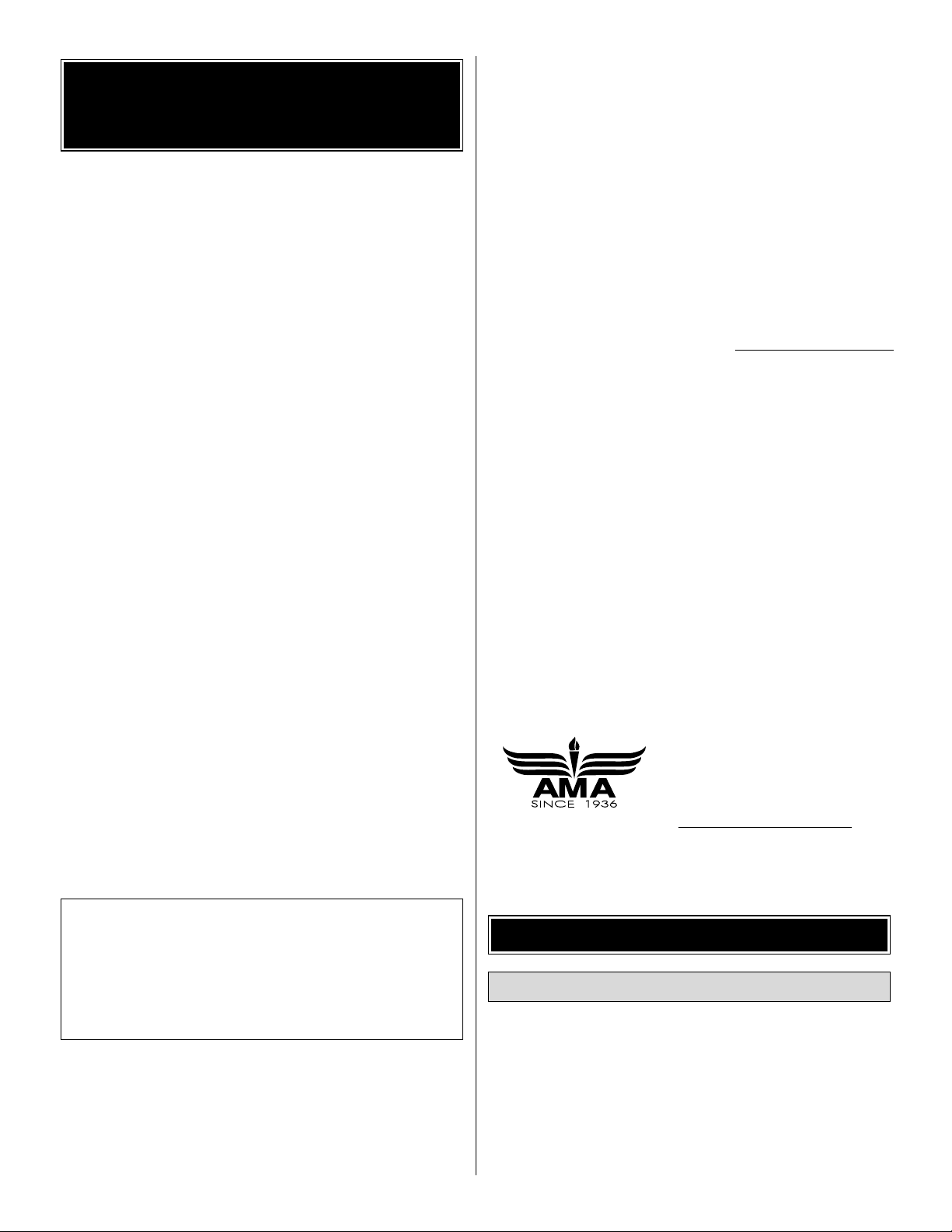
The engine you select will determine where the throttle
pushrod is routed and also how the cowl is cut out, so it
is important that you have the engine close at hand
while building.
The recommended engine size range is as follows:
.40 - .61 cubic inch displacement 2-cycle
.48 - .80 cubic inch displacement 4-cycle
Engine Selection
DECISIONS YOU MUST MAKE
Academy of Model Aeronautics
5151 East Memorial Drive
Muncie, IN 47302
Tele: (800) 435-9262
Fax (765) 741-0057
Or via the Internet at:
http://www.modelaircraft.org
We, as the kit manufacturer, provide you with a top
quality, thoroughly tested kit and instructions, but
ultimately the quality and flyability of your finished model
depends on how you build it;therefore, we cannot in any
way guarantee the performance of your completed
model, and no representations are expressed or implied
as to the performance or safety of your completed model.
PRO TECT YOUR MODEL,YOURSELF
& OTHERS...FOLLOW THESE
IMPORTANT SAFETY PRECAUTIONS
3
Page 4
For the best scale effect, an OS .48 Surpass 4-cycle is
ideal. For maximum aerobatics, an OS .70 Surpass 4-cycle
is all the power you will need.
This kit includes a Great Planes EM4070 engine mount
that fits most .40 - .60 2-cycle engines and most 40 - .70
4-cycle engines.
This kit includes everything you need to build either the
standard or the clipped wing for your Cub. Both versions fly
extremely well and are equally easy to construct. The
standard wing makes the Cub a real “Floater” giving you
plenty of time to think about your maneuvers. The clipped
wing allows things to happen a bit quicker.Snaps, rolls and
spins can be performed faster and more precisely. Either
way, the model flies much like the real plane.
If you install a 2-cycle engine, we recommend using a
muffler that can be partially enclosed inside the cowl. The
muffler shown in the instruction book photos is a Slimline
#3217 Pitts Style Muffler for OS MAX .61SF and .60FP
engines. If you use a OS .40SF or .46SF use a Slimline
#3218 Pitts Style Muffler or similar. Most standard mufflers
will require an extension to clear the fuselage sides.
❏ Engine, prop nut, and suitable propellers
❏ 4-Channel radio with 4 standard ser vos
❏ 1/4" [6mm] R/C foam rubber (HCAQ1000)
❏ 10 or 12 oz. Fuel tank (GPMQ4104 or GPMQ4105)
❏ 3' [900mm] Standard silicone fuel tubing (GPMQ4131)
❏ 3-3/8" Main wheels, Cub Style (GPMQ4230)
❏ 1-1/4" Tail wheel (GPMQ4242)
❏ (4) 3/16" Wheel Collars (GPMQ4308)
❏ (2) 3/32" Wheel Collars (GPMQ4302)
❏ (2) Rolls Top Flite
®
MonoKote®covering (TOPQ0220,
Cub Yellow)
In addition to common household tools (screwdrivers, drill,
etc.), this is the “short list” of the most important items
required to build the Piper J-3 Cub .40.
We recommend
Great Planes Pro™CA and Epoxy glue.
❏ 2 oz. Thin Pro CA (GPMR6003)
❏ 2 oz. Medium Pro CA+ (GPMR6009)
❏ Pro 6-minute epoxy (GPMR6045)
❏ HobbyLite
™
balsa-colored balsa filler (HCAR3401)
❏ Plan Protector
™
(GPMR6167) or wax paper
❏ Dr ill bits: 1/16" [1.6mm], 5/64" [2.0mm], 3/32" [2.4mm],
7/64" [2.8mm], 1/8" [3.2mm], 9/64" [3.6mm],
11/64" [4.4mm], 3/16" [4.8mm], 1/4" [6.4mm]
❏ Small metal file
❏ Stick-on segmented lead weights (GPMQ4485)
❏ Silver solder w/flux (GPMR8070)
❏ #1 Hobby knife (HCAR0105)
❏ #11 Blades (100-pack, HCAR0311)
❏ Single-edge razor blades (10-pack, HCAR0212)
❏ Small T-pins (100, HCAR5100)
❏ Medium T-pins (100, HCAR5150)
❏ Sanding tools and sandpaper assor tment (see
Expert
Tip–Easy-Touch™Bar Sander
section on page 5)
❏ Top Flite
®
MonoKote®sealing iron (TOPR2100)
❏ Top Flite MonoKote heat gun (TOPR2000)
Here is a list of optional tools mentioned in the manual that
will help you build the Piper J-3 Cub .40.
❏ Pro Aliphatic resin (2 oz. [60g], GPMR6160)
❏ 2 oz. [57g] Spray CA activator (GPMR6035)
❏ CA applicator tips (HCAR3780)
❏ CA debonder (GPMR6039)
❏ Epoxy brushes (6, GPMR8060)
❏ Mixing sticks (50, GPMR8055)
❏ Mixing cups (GPMR8056)
❏ Razor plane (MASR1510)
❏ Builder’s triangle set (HCAR0480)
❏ 36" Metal r uler (HCAR0475)
❏ Cur ved-tip canopy scissors (for trimming plastic parts,
(HCAR0667)
Optional Supplies & Tools
Covering T ools
Adhesives & Building Supplies
Required Accessories
REQUIRED ITEMS
Muffler Selection
Wing Configuration
4
Page 5
❏ Pliers with wire cutter (HCAR0630)
❏ Robar t Super Stand II (ROBP1402)
❏ 18" x 24" [460 x 610mm] Builder’s cutting mat (HCAR0455)
❏ 16" x 48" [410 x 1220mm] Building board (GPMR6950)
❏ Masking tape (TOPR8018)
❏ Threadlocker
™
thread locking cement (GPMR6060)
❏ Denatured alcohol (for epoxy clean up)
❏ Z-bend pliers (HCAR2000)
❏ Rotar y tool such as Dremel
®
Moto-Tool
®
❏ Rotar y tool reinforced cut-off wheel (GPMR8200)
❏ Ser vo horn dr ill (HCAR0698)
❏ Dead Center
™
Engine Mount Hole Locator (GPMR8130)
❏ AccuThrow
™
Deflection Gauge (GPMR2405)
❏ Slot Machine
™
hinge slotting tool (110V, GPMR4010)
❏ CG Machine
™
(GPMR2400)
❏ Laser incidence meter (GPMR4020)
❏ Precision Magnetic Prop Balancer
™
(TOPQ5700)
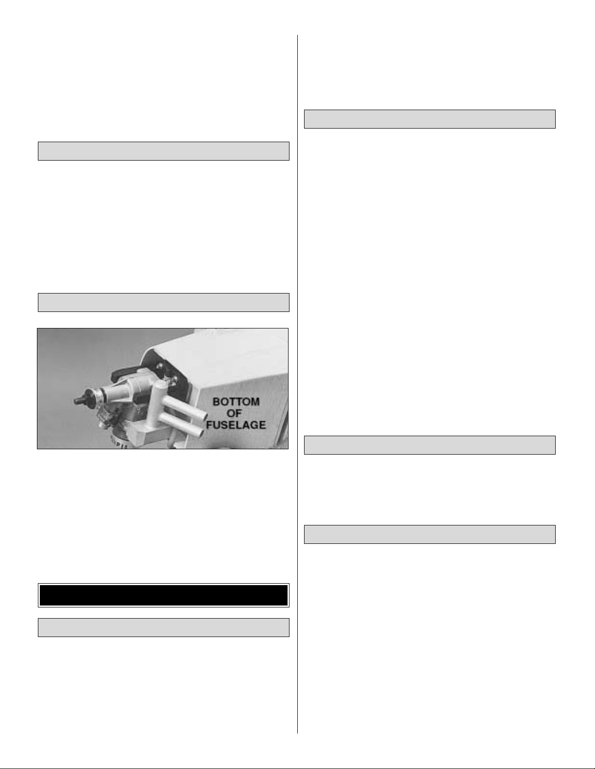
EASY-TOUCH™BAR SANDER
A flat, durable, easy to handle sanding tool is a necessity f or
building a well finished model. Great Planes makes a
complete range of Easy-Touch Bar Sanders and replaceable
Easy-Touch Adhesive-backed Sandpaper.While building the
P-38 Profile, two 5-1/2" [140mm] Bar Sanders and two 11"
[280mm] Bar Sanders equipped with 80-grit and 150-grit
Adhesive-backed Sandpaper were used.
Here’s the complete list of Easy-Touch Bar Sanders and
Adhesive Backed Sandpaper:
5-1/2" Bar Sander (GPMR6169)
11" Bar Sander (GPMR6170)
22" Bar Sander (GPMR6172)
33" Bar Sander (GPMR6174)
44" Bar Sander (GPMR6176)
11" Contour Multi-Sander (GPMR6190)
12' roll Adhesive-backed 80-grit sandpaper (GPMR6180)
150-grit (GPMR6183)
180-grit (GPMR6184)
220-grit (GPMR6185)
Assortment pack of 5-1/2" strips (GPMR6189)
We also use Top Flite 320-grit (TOPR8030, 4 sheets) and
400-grit (TOPR8032, 4 sheets) wet-or-dry sandpaper for
finish sanding.
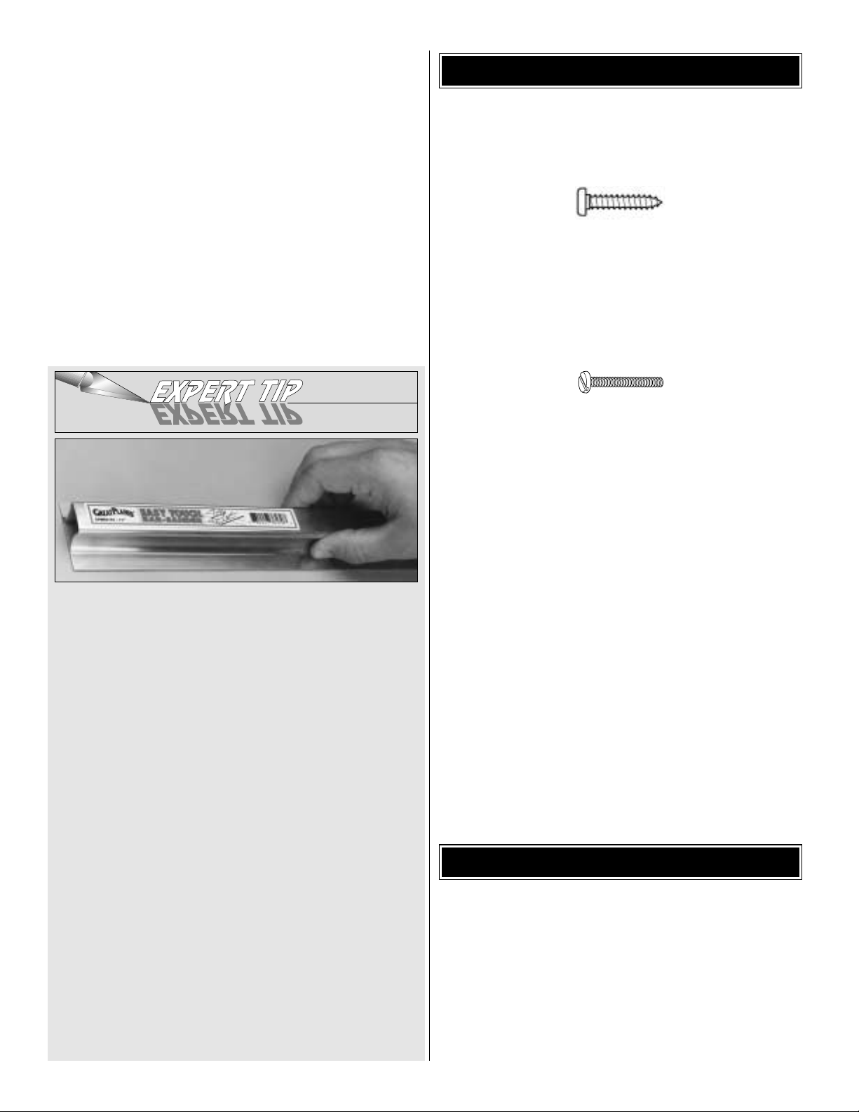
• There are two types of screws used in this kit:
Sheet metal screws are designated by a number and a length.
For example #6 x 3/4"
This is a number six screw that is 3/4" long.
Machine screws are designated by a number, threads
0per inch, and a length. SHCS is just an abbreviation for
“socket head cap screw”and that is a machine screw with a
socket head.
For example 4-40 x 3/4".
This is a number four screw that is 3/4" long
with forty threads per inch.
• When you see the term
test fit
in the instructions, it
means that you should first position the part on the
assembly without using any glue, then slightly modify or
custom fit the part as necessar y for the best fit.
• Whenever the term
glue
is written you should rely upon
your experience to decide what type of glue to use.When a
specific type of adhesive works best for that step, the
instructions will make a recommendation.
• Whenever just
epoxy
is specified you may use
either
30-minute (or 45-minute) epoxy or6-minute epoxy. When
30-minute epoxy is specified it is highly recommended that
you use only 30-minute (or 45-minute) epoxy, because you
will need the working time and/or the additional strength.
•
Photos
and
sketches
are placed before the step they
refer to. Frequently you can study photos in following steps
to get another view of the same parts.
Fuse = Fuselage
Stab = Horizontal Stabilizer
Fin = Ver tical Fin
LE = Leading Edge
TE = Trailing Edge
LG = Landing Gear
Ply = Plywood
" = Inches
mm = Millimeters
SHCS = Socket Head Cap Screw
COMMON ABBREVIATIONS
IMPORTANT BUILDING NOTES
5
Page 6
1.Unroll the plan sheet.Re-roll it inside out to make it lie flat.
2. Remove all parts from the box. As you do, figure out the
name of each part by comparing it with the plans and the
parts list included with this kit. Using a felt-tip or ballpoint
pen, lightly write the part name or size on each piece to
avoid confusion later. Use the die-cut drawings shown on
page 7 to identify the die-cut parts and mark them before
removing them from the sheet. Save all scraps. If any of
the die-cut parts are difficult to punch out, do not force
them! Instead, cut around the parts with a hobby knife.After
punching out the die-cut parts, use your Bar Sander or
sanding block to lightly sand the edges to remove any diecutting irregularities or slivers.
GET READY TO BUILDTYPES OF WOOD
6
DIE-CUT DRAWINGS
Page 7
7
1/64" = .4 mm
1/32" = .8 mm
1/16" = 1.6 mm
3/32" = 2.4 mm
1/8" = 3.2 mm
5/32" = 4.0 mm
3/16" = 4.8 mm
1/4" = 6.4 mm
METRIC CONVERSIONS
3/8" = 9.5 mm
1/2" = 12.7 mm
5/8" = 15.9 mm
3/4" = 19.0 mm
1" = 25.4 mm
2" = 50.8 mm
3" = 76.2 mm
6" = 152.4 mm
12" = 304.8 mm
18" = 457.2 mm
21" = 533.4 mm
24" = 609.6 mm
30" = 762.0 mm
36" = 914.4 mm
DIE-CUT DRAWINGS
Page 8
8
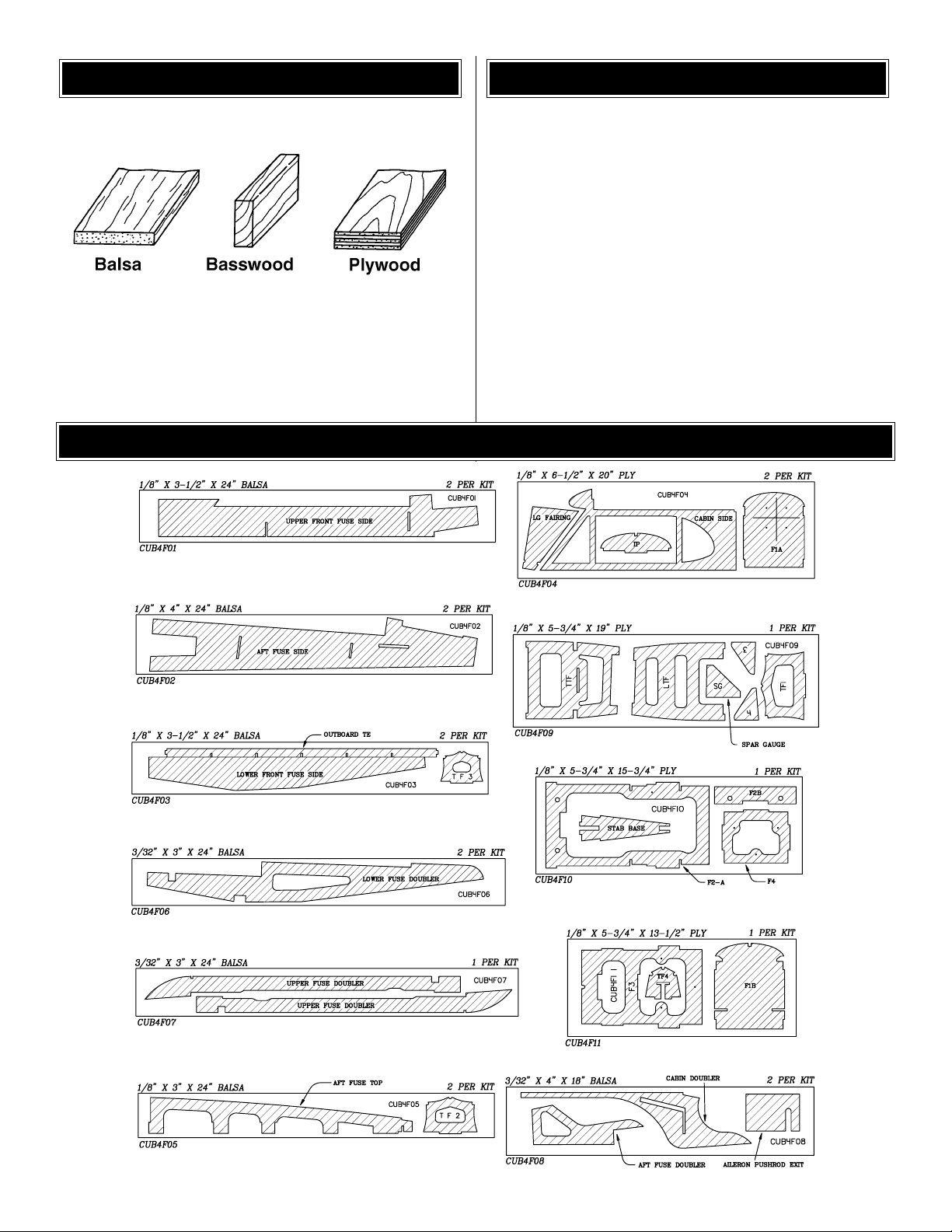
❏ 1. Tape waxed paper over the Rudder drawing on the
fuse plans. Remove the die-cut 1/4” balsa par ts R2,R3,R4
and R5 from CUB4RO1. Place all the parts over the plan in
their locations and check the joints for good fits.Use a T-bar
or other flat sanding block to make any necessary
adjustments.Pin the parts to the building board after proper
alignment and fitting has been done.
❏ 2. Cut the rudder LE from the 1/4" x 3/4" x 24" balsa
strip (CUB4SO3). NOTE: Look over the three CUB4S03’s
and mark the straightest one to be used later for the stab
TE. Fit the LE into the notch in R3 and against the edge of
R5. Cut the horizontal frame section from the 1/4" x 3/4"
balsa strip and fit it in position. Pin the LE and horizontal
frame section in place and securely glue all joints with thin
CA. Wipe any excess glue off with a paper towel before it
cures (this will make sanding much easier).NOTE:Leave all
the parts pinned to the building board.
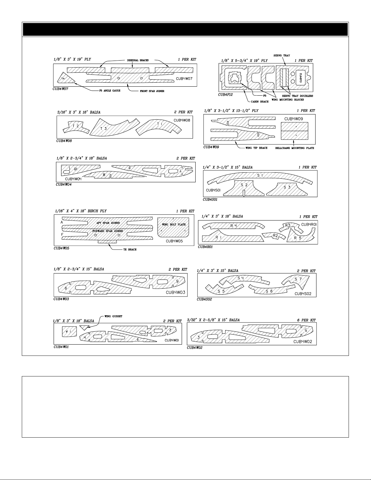
❏ 3. Cut the four Ribs from the 3/16” x 1/4” x 24” balsa
stick (CUB4SO4). Fit the ribs into the rudder frame and
securely glue them in place with thin CA.
❏ 4. Remove the Rudder from the building board and
inspect all the glue joints on the bottom side.Add thin CA to
all the tight fitting joints and thick CA to any open joints.
NOTE: The process of re-gluing the joints on the bottom
side is necessary on the thick balsa parts. This will ensure
the complete wicking of the CA throughout the entire joint.
❏ 5. Place the Rudder on a flat work surface and lightly
sand both sides flat and smooth using a T-Bar or good flat
sanding block with medium grit sandpaper.
❏ 6. Carefully draw a centerline on the LE and TE of the
rudder. This will help you to maintain symmetry when
sanding these edges.
❏ 7. Using a flat sanding block, sand the top and theTE of
the rudder to a rounded shape. Sand the LE to a “V-shape”
as shown on the plans.
Build the Rudder
TAIL FEATHERS
Page 9
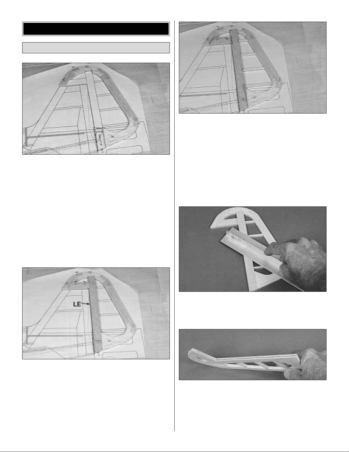
❏ 8. Check the plans and mark the location of the tailgear
on the rudder.Drill a 7/64” hole in the rudder 3/4” deep (the
hole is drilled slightly oversize to allow room to create a hard
epoxy “sleeve”around the wire).Then groove the rudder LE
to accept the tailgear wire.
Using a hobby knife, sharpen the inside of one end of a
1/8" diameter brass tube, and use it to cut the groove in
the LE of the rudder as shown below.
❏ 1. Tape waxed paper over the Fin drawing on the fuse
plans. Remove the 1/4” die-cut balsa R1 from (CUB4RO1).
Place R1 on the plan and pin in place.
❏ 2.Cut the remaining fin frame parts from the 1/4" x 3/4"
x 24" balsa strip (CUB4SO3). Pin the par ts in place and
make sure all the joints are good and tight.Securely glue all
the joints with thin CA. Note: The bottom end of the trailing
edge stops at the top edge of the horizontal stabilizer.
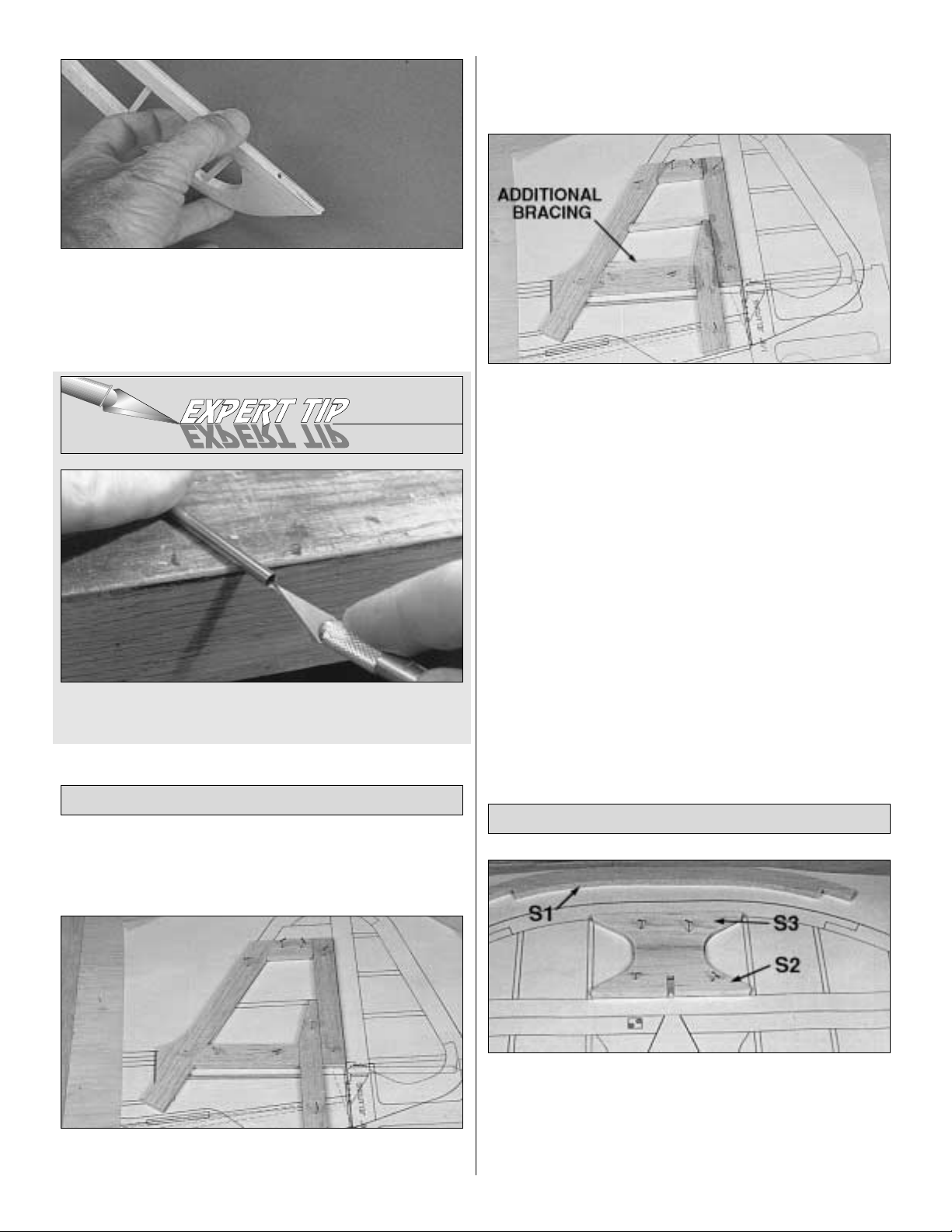
❏ 3. Cut three Ribs from the 3/16" x 1/4" x 24" balsa stick
(CUB4SO4).Fit one rib in place and glue it with thin CA.Add
two more ribs for additional bracing above the lower frame.
❏ 4. Remove the Fin from the building board and inspect all
the glue joints.Glue all the tight fitting joints on the bottom side
of the fin with thin CA and add thick CA to any open joints.
❏ 5. Place the Fin on a flat work surface and lightly sand
both sides flat and smooth.
❏ 6. Draw a centerline on the LE and TE of the fin. The
lines will assist you in the final shaping of the LE and hinge
positioning on the TE.
❏ 7. Sand the LE only to a rounded shape to match the
cross-section shown on the plans. NOTE: The trailing edge,
bottom edge and top edge must not be rounded or V -shaped.
Instead, just sand these edges flat and square.
❏ 1. Tape waxed paper over the Stabilizer drawing on the
fuse plan.Remove the die-cut 1/4" balsa parts S1, S2 and S3
from (CUB4SO1) and the two S4’s from (CUB4S02). Place
S2 and S3 over the plan to check their fit together.Sand the
parts as necessar y to ensure a good fitting joint. Pin S2 and
S3 in place over the plans and glue them together.
Build the Stabilizer
Build the Fin
9
Page 10
❏ 2. Position the S1 and the two S4’s over their locations
on the plans. Check the fits of the joints and sand them if
necessary. Pin them in place.
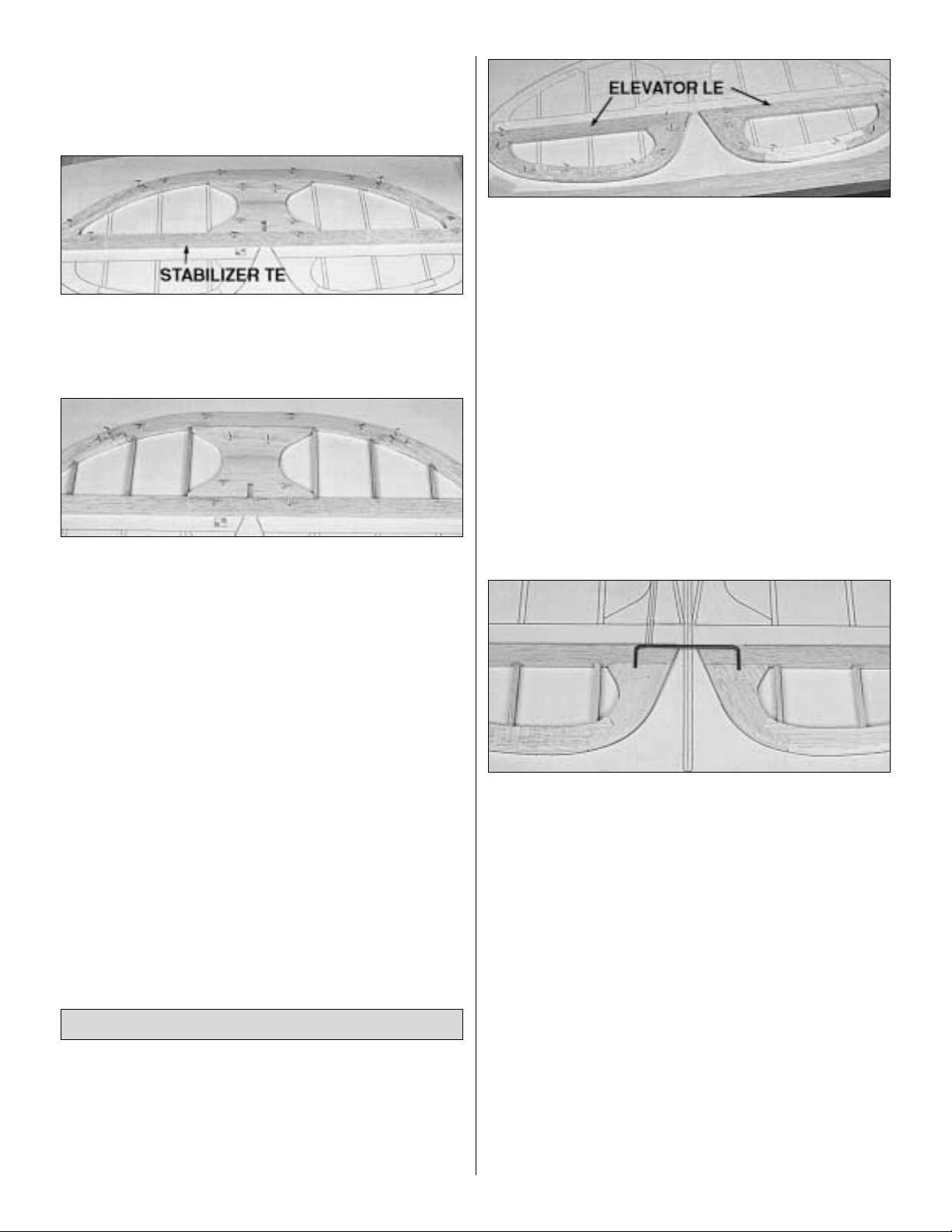
❏ 3.Cut the Stabilizer TE from the 1/4" X 3/4" X 24" balsa
strip (CUB4S03). Fit the TE between the S4’s and glue it in
place with thin CA.
❏ 4. Cut the Ribs from the 3/16" x 1/4" x 24" balsa stick
(CUB4S04). Fit the Ribs in the stabilizer frame and glue
them in place with thin CA.
❏ 5. Remove the stabilizer from the building board and
inspect all the glue joints. Glue all the tight fitting joints on
the bottom side of the stab with thin CA and add thick CA to
any open joints.
❏ 6. Place the stabilizer on a flat work surface and lightly
sand both sides flat and smooth.
❏ 7. Draw a centerline on the TE of the stabilizer. The
centerline will be used later to assist in positioning the hinges.
❏ 8. Sand the LE only of the stabilizer to a nice rounded
shape as shown on the plans.
❏ 1.Tape waxed paper over the Elevator drawing on the
fuse plan.Remove S5,S6,and S7 from the 1/4" die-cut balsa
sheet CUB4S02. Position the parts over the plans and
check the fit of the joints. Sand the parts as necessar y to
ensure good fitting joints. Pin the parts in place over the
plans and glue them together with thin CA.
❏ 2. Cut the Elevator LE from the 1/4" x 3/4" x 24" balsa
strip (CUB4S03) and pin it in place. Glue all the joints with
thin CA.
❏ 3. Cut the elevator Ribs from the 3/16" x 1/4" x 24" balsa
stick (CUB4SO4).Fit the ribs in the elevator frame and glue
with thin CA.
❏ 4. Remove the elevators from the building board and
inspect all the glue joints. Glue all the tight fitting joints with
thin CA and add thick CA to any open joints.
❏ 5. Place the elevators on a flat wor k surface and lightly
sand both sides flat and smooth using a T-bar or other good
flat sanding block.
❏ 6. Carefully draw a centerline all around the edges of
the elevators.
❏ 7. Temporarily pin the elevators to the plan. Lay the 1/8"
wire elevator joiner (WBNT194) in place on the elevators
and mark its outline using a soft leaded pencil. NOTE: Mark
the elevator joiner wire outline very lightly so that it will not
be seen through the covering material.
❏8.Accurately drill a 1/16" diameter pilot hole approximately
3/4" deep at each location. Then drill the final hole with a
9/64" drill bit to a depth of 7/8". (The hole is drilled slightly
oversize to allow for positioning, and to allow room to create
a hard epoxy “sleeve”around the wire.NOTE:The joiner wire
must be centered on the centerline of the stabilizer.The holes
must be drilled perpendicular to the LE and parallel to the top
and bottom surfaces of the elevators.
❏ 9. Use the shar pened 1/8" diameter brass tube to cut
grooves in the leading edge of the elevators to accept the
joiner wire.
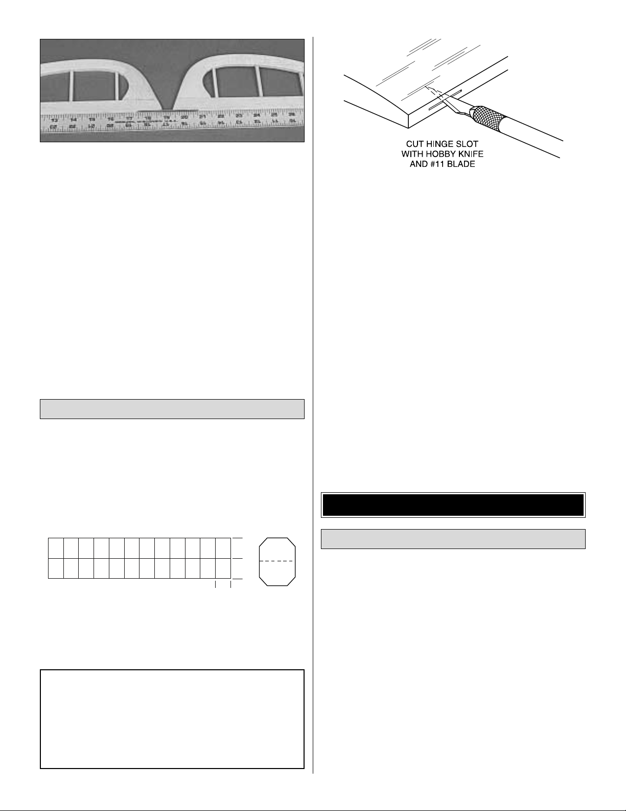
❏ 10. Sand the LE to a “V”-shape and the entire TE to a
rounded shape.Check the plans for the proper cross-sections.
Build the Elevators
10
Page 11
❏ 11.Test fit the joiner wire into both elevators.Position the
elevators against a straight edge to chec k f or str aightness of
the LE with the joiner wire installed. Adjust the holes if
needed to achieve a straight LE.
❏ 12. Roughen the joiner wire with coarse sandpaper,
then clean the wire thoroughly with alcohol to remove any
oily residue.
❏ 13.Glue the joiner in place using 30-minute epoxy.When
gluing, lay the elevators on a flat surface with the leading
edges along a straightedge to ensure perfect alignment.
NOTE: A strip of Ultra-Grip hinges are supplied in this
kit. If you choose to use the “pinned”-type hinges, you
should cut the hinge slots at this time. However, if you
choose to use the Ultra-Grip hinges that are furnished
in this kit, you may wait until after covering before
cutting the hinge slots. The strip of Ultra-Grip hinges
must be cut as shown in the sketch below.
❏ 1.Lay the rudder and elevators on the plan and mark the
hinge locations. Place the rudder against the fin TE and
transfer the marks over to the fin. Place the elevators
against the stab TE and transfer the marks over to the stab.
❏ 2. Cut the hinge slots on the centerlines which you
previously drew, using a hobby knife following the
recommended hinge slotting technique listed below. NOTE:
For pinned hinges use a slotting fork and slotting hook.
❏ A. Begin by carefully cutting a very shallow slit at the
hinge location. This first cut is to establish your cut in the
right place, so concentrate on staying on the centerline and
don’t cut too deep!
❏ B.Make three or four more cuts in the same line, going
slightly deeper each time. As you make these additional
cuts, work on going straight into the wood. Continue this
process while “wiggling” the knife handle back and forth
until the blade has reached the proper depth for the hinge.
❏ C.Trial fit the hinge into the slot. If the hinge is difficult
to push in, re-insert the knife and move it back and forth in
the slot a few times to enlarge the slot.
❏ 3. Inser t the hinges into the slots and trial fit the rudder
and elevators in place on the fin and stab. Do not glue the
hinges until after you have covered the model.
NOTE: It will be helpful to build the wing on a piece of
“Celotex” or other semi-soft (and flat) surface, into
which you may easily stick pins to firmly hold down the
wing parts while building, to avoid warps.
NOTE: You may build one of two different wings from
this kit. The standard scale wing or the clipped wing
version.You will need to decide now which version you
would like to build. Regardless of your decision, the
wings LE's and TE's will require trimming. Carefully
study the LE and TE trim diagram on the wing plan. Lay
the LE and TE directly over the plan and trim
accordingly. No change to the plans is necessary for the
standard scale wing. If you decide to build the clipped
wing version, cut the plans on the dashed lines. Slide
the outer halves of each wing panel over the inner
halves and match the registration marks between the
Build the Wing Panels
WING ASSEMBLY
CAUTION!!!: You must use extreme care when
cutting hinge slots with a hobby knife, to avoid
cutting yourself! If the balsa part breaks while you
are pushing on the knife, the blade could go into
your hand before y ou know it! A good precaution is
to wear leather gloves while performing the
following steps,and always cut
away
from yourself .
Cut the Hinge Slots
11
1"
1"
3/4"
Page 12

first two #3 ribs. Keep the plans aligned and tape the
inner and outer halves together. The plans are now
ready to use for the clipped wing version.
❏1.T ape the plan to your flat work surface .Align a straightedge
on the wing centerline and draw a continuous line extending out
past the leading and trailing edges.Do this for both the right and
left wing panel plans. This centerline will be used at various
times during the wing construction. Cover the wing drawing with
waxed paper (so you won’t glue the wing to the plan!).
❏ 2. Before using the 3/8" x 3/8" x 33-1/2" bass woodSpars
(CUB4W06), examine them carefully for possible
imperfections.Look for knots, soft spots, diagonal grain and
any other imperfections. If possible, position each spar so
the imperfections are on the outer half of the wing panel
(toward the tip), where they will be least affected by high
stress. If the spars are warped slightly, try to “balance them
out” by installing the warped spars in opposite directions.
❏ 3. Carefully punch out all the die-cut 3/32" balsa #3 and
#5 ribs (CUB4W02) and the die-cut 1/8" balsa #2, #4,#6, #7
and #8 ribs (CUB4W01, CUB4W03 and CUB4W04). Sand
the edges slightly to remove any die-cutting irregularities.
❏❏4. Place one of the 3/8" x 3/8" x 33-1/2" Basswood
Spars (CUB4W09) on the wing plan and pin the spar down
with crossed T-pins as shown in the follo wing sk etch.NOTE:
Align the end of the spar with the outboard edge of rib #7.
The spars are cut slightly too long, and the excess will be
cut off later at the center of the wing.
❏❏5. Place the 1/16" x 1-3/8" x 36" balsa TE Sheeting
(CUB4W13) on the plans but do not pin it yet.Align one end
of the sheeting with the wing centerline.
❏❏6. Place three of the #3 ribs and one of the #4 r ibs on
the spar in their locations shown on the plans, but do not
glue. Slide the TE sheeting to the forward edge of the
notches in the bottom of the ribs. The TE sheeting is used
only as a shim for the rib ends at this point.
❏❏7.Carefully check the notches on the TE (CUB4W11).
The 1/8" wide notches are to be positioned over the #1 and
#2 rib locations on the plans. Align the outboard end of the
TE with the aft end of the #4 rib.Insert the aft ends of the #3
ribs into the notches in the TE.Make sure the ribs are down
against the sheeting and building board and glue the ribs to
the spar and the TE with thin CA.The TE sheeting should
hold the ribs 1/16" above the work surface.
❏❏8. Slide the bottom sheeting back against the TE and
align it with the inboard end of the TE. Glue the bottom
sheeting to the TE and the ribs.
NOTE: Follow steps 4 through 30 to build the LEFT
wing panel, then repeat these steps to build the
RIGHT wing panel.
12
T-Pin
Spar
Work Surface
Page 13
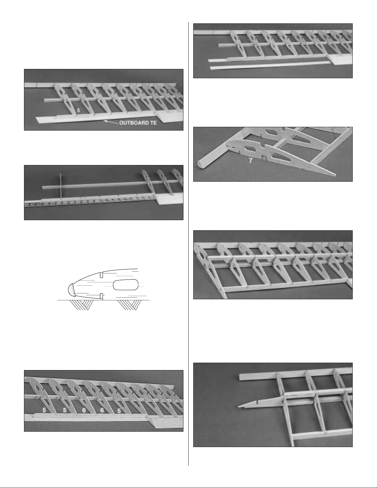
❏❏9. Carefully inspect the notches in the die-cut 1/8"
balsa Outboard TE (CUB4F03). The 1/8" wide notches are
to be aligned with the #6 rib locations. Insert the tab on the
die-cut outboard TE into the slot at the aft end of the #4 rib,
with the notches facing up.
❏❏10.Place the outboard #5 rib on the spar at the proper
location and insert the aft end of the rib into the proper notch
in the outboard TE.Do not glue yet!
❏❏11. Use a straightedge to keep the outboard TE straight
as shown in the photo and glue it to the bottom TE sheeting with
thin CA. Be careful not to glue the straightedge to the sheeting.
❏❏12. Position the notched LE so the 1/8" wide notches
are near the #2, #4, #6, #6 and #7 positions. Place it on the
ribs so the ribs are centered vertically on the LE to allow for
the LE sheeting which will be installed later.Glue it in place
with thin CA.
❏❏13. Install the remaining #5 and #6 ribs. Glue them to
the LE, the spar, the outboard TE and the bottom TE
sheeting. Make sure they are centered on the LE and down
against the bottom TE sheeting.
❏❏14.Trim the bottom sheeting in the aileron area, along
the #4 rib and the outboard TE to the end of the sheet.
Maintain a straight cut past the #7 rib location.You may want
to slide a thin piece of hard plastic under the bottom sheeting
to avoid cutting into the plans when making this cut.
❏❏15.Position the #7 rib in place over the plans and onto
the tab at the end of the outboard TE.Glue the rib to the LE,
the front and top edges of the spar, the outboard TE and
the bottom TE sheeting.Trim the bottom sheeting even with
the outboard edge of the #7 rib.
❏❏16. Insert the 3/8" x 3/8" basswood Top Spar
(CUB4W09) into the notches in the ribs. Align the end of the
spar to the outboard edge of the #7 rib. Glue the spar to all
the ribs, with the spar against the front of the notch in the #7
rib.Make sure the top surface of the spar is level with the top
edges of the ribs. NOTE: Check to make sure the spar is
positioned properly to ensure a straight wing (see step 2).
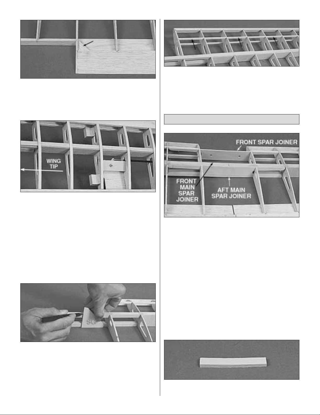
❏❏17. Install a die-cut 1/8" plywood Wing Tip Brace
(CUB4W09) at the rear of the spars through the notches in
13
Page 14

the #7 rib. Align the top notch in the wing tip brace with the
#8 rib on the plans and glue the brace in place. Make sure
the “legs” of the brace are parallel with the spars.
❏❏18. If you are currently building the left wing panel,
assemble the wing tips over the right wing panel plan.Place
the die-cut 3/16" balsa Wing Tip parts T1, T2 and T3
(CUB4W08) over the plans and check all joints for proper
fits. Sand the par ts if necessary for good fitting joints. Pin
them in place and glue the pieces together with thin CA.
❏❏19. Remove the Wing Tip from the building board and
inspect all the glue joints on the bottom side. Add thin CA to
all the tight fitting joints and add thick CA to all the open joints.
❏❏20. Place the Wing Tip on a flat work surface and
lightly sand both sides flat and smooth.
❏❏21. Sand the front edge of the Wing Tip to match the
angle of the LE.Test fit the wing tip into the slot at the front of
rib #7 and align the aft end of the wing tip with the aft end of rib
#7. Glue the wing tip to the LE, the wing tip brace and rib #7.
❏❏22.Insert rib #8 into the notch in the wing tip brace so
the ends of the rib rest on the wing tip.Align the rib over the
plans and glue it in place. Sand the top and bottom outside
edges of the wing tip to remove the sharp corner where the
leading edge sheeting will be attached later.
❏❏23. Install rib #2 by sliding it in between the spars and
twisting it into place. Center it on the LE and glue it with thin
CA. Do not glue it to the spars yet! Note: Maintain a 1/16"
gap between the bottom edge of the rib and the work surface
to allow for the center sheeting which will be installed later.
Use a scrap piece of 1/16" balsa to hold the rib up off the
work surface.
❏❏24. Securely glue eight (six for the clipped wing Cub)
of the pre-cut 1/16" x 2-7/8" x 1-7/16" balsa vertical grain
shear webs (CUB4W20) to the rear surface of the spars,
starting between the two #5 ribs near the wing tip end of the
wing and working towards the center of the wing.Medium or
thick CA works best for this. Securely glue a shear web to
the front surfaces of the spars in the two rib bays between
the #3 r ibs as shown in the next photo.
❏❏25.Install the 1/8" x 1/4" x 33-1/2" balsa T op Forwar d
Spar (CUB4W12) in the forward rib notches, starting with
the #7 rib. Press the spar down fir mly into the notches and
glue it in place with thin CA. Trim the forward spar and LE
even with the inboard side of the #2 rib and even with the
outboard side of the #7 rib.
❏❏26.Position f our 1/4" x 3/8" x 1-1/2" balsa Hinge Blocks
(CUB4W21) against the Outboard TE at the locations shown
on the plans and glue them in place with CA. Notice that they
are centered vertically on the outboard TE and not placed
down against the bottom TE sheeting.
14
Page 15
❏❏27. Place the die-cut 1/8" balsa triangular Gusset
(CUB4W01) in the corner formed by the #4 rib and the
tapered TE.Securely glue it in place.
(Photo taken at a later stage of completion.)
❏❏28. Glue the 1/2" x 3/4" x 1" basswood Wing Strut
Mounting Blocks (CUB4W22) to the outboard side of the
second #6 rib.They should be flush with the bottom of the rib
and positioned as shown on the plans.Cut four 1" long pieces
of 3/8" balsa Triangle (CUB4W24) and glue one piece on top
of each mounting block. There are six of these blocks
included in this kit, two of which are (CUB4F20). The strut
mounting blocks must be down flat on the building surface
when gluing it to the rib.The front block will be flush with the
bottom of the rib, but the aft block will be 3/32" below the
bottom edge of the rib because the balsa sheeting has not yet
been installed in the bellcrank bay.
❏❏29. Use the die-cut 1/8" ply Spar Gauge (CUB4F09)
to mark where to cut the spars and TE off. Hold the gauge
flat against the work surface and line it up with the centerline
on the plans. Mar k along the almost vertical edge and then
cut the spars off along these lines. This will make the top
spar slightly shorter than the bottom spar to allow for the
dihedral angle.In addition to the spars, mark and cut off the
bottom TE sheet and the tapered TE at the wing centerline.
❏❏30.Remove the wing panel from the work surface and
install the 1/8" x 1/4" x 33-1/2" Bottom Forward Spar
(CUB4W12) following the same procedure used in step 25.
❏ 31. Go back to step 4 and build the other wing panel.
❏1. Using the die-cut 1/8" ply Front Spar Joiner(CUB4W07)
and the die-cut 1/16" ply Forward and Aft Main Spar Joiners
(CUB4W05), test fit (DO NOT GLUE) the two wing panels
together. With the center of the wings resting on the work
surface, block up both wing tips 5/8" (1/2" for the clipped wing)
as measured from the work surface to the bottom of rib #7.
Check the fit of the spars and the TE to make sure they meet
up nicely without producing any sweep in the wing. Take the
panels apart and sand the spars or TE’s if necessary to achieve
the correct alignment. NOTE: The holes in the die-cut 1/8"
plywoodFront Spar Joiner and the holes in the die-cut1/16" ply
Forward Main Spar Joiner must be centered on the centerline
of the wing.Make sure you trim the ends of the spar joiners as
needed to allow the wing panels to come together and the
spars to touch. It is typical to have to trim 1/16"from the ends
of the joiners.It is also likely likely that you will have to deepen
the notches in the #2 ribs slightly to allow the joiners to slide
fully into place.
❏ 2. Glue the three die-cut 1/8" plywood Dihedral Braces
(CUB4W07) together as shown in the photo.
Joining the Wing Panels
15
Page 16

❏ 3.Tr ial fit the dihedral brace between the main spars of
the wing. Sand the edges of the dihedral brace if necessary
to get it to fit without forcing the spars apart.
❏ 4. IMPORTANT: Use a good quality non-brittle epoxy
for this task,such as Great Planes Pro 30-minute Epo xy.
Place waxed paper on the work surface and mix up a batch
of epoxy. Apply it to the top and bottom of the dihedral brace,
the spar joiners, the spars, spar ends and the ends of both
TE’s.Apply plenty of epoxy, to fully fill all voids at the center
of the wing. Slide the spar joiners and the dihedral brace
into one wing panel first. Slide the other wing panel into
place and wipe off any excess epo xy. Immediately proceed
to the next step.
❏ 5. Block up each wing panel 5/8" (1/2" for the clipped
wing) as measured from the work surface to the bottom of rib
#7. Carefully align the spars and the TE of both wing panels.
Clamp the spar joiners to the spars and wipe off any excess
epoxy with a paper towel.Allow the epoxy to fully harden
before disturbing the wing and removing the clamps.
Wipe out any excess epoxy in the holes in the forward main
spar joiner.
❏ 6. Securely glue the remaining four 1/16" balsa vertical
grain shear webs to the front and back sides of the main
spar joiners between the #2 and #3 ribs.
❏ 7. Install the two #1B ribs as shown in the photo.The top
surface of each rib should be flush with the top surface of
the spars.
❏ 8. Round off one end of each 1/4" x 3" hardwood Wing
Dowel (DOWEL017). Slightly chamfer the other end of each
dowel.Slide the chamfered end of both dow els into the wing
and securely glue them to both spar joiners with either thick
CA or epoxy.
❏ 9. Install the two #1A ribs as shown in the photo.The top
surface of each rib should be flush with the top surface of
the spars.
16
Page 17

❏ 10. Glue the die-cut 1/16" ply TE Joiner (CUB4W05) in
place between the #1B ribs as shown in the photo.
❏ 11. Glue the 5/16" x 3/8" x 1" basswood Aileron Servo
Rails (CUB4W22) to the inboard sides of both #1B ribs as
shown on the plans.Line up the front edge of each servo rail
with the embossed angled line near the back of the pushrod
hole in the ribs.The embossed line will be on the wrong side
of one rib, but you can still eye it while positioning the servo
rail. NOTE: If you are using a servo smaller than a Futaba
S148, you may need to glue a spacer between the servo
rails and the ribs to correctly space the rails to fit your servo.
❏ 12. Cut all the arms except one off of a large servo horn
and mount the Threaded Ball (SCRW058) in the outer hole
of the arm as shown in the photo. Install the arm on the
servo so it is perpendicular to the servo (neutral position).
(Wing is upside down in photo.)
❏ 13. Hold your aileron servo in position against the servo
rails and mark where to drill the mounting holes. Drill 1/16"
holes at each mark and mount your servo using the screws
provided with the servo. NOTE: The screws are installed
from the bottom side of the servo lugs.
❏ 14.Drill a 1/8" hole at the punch mark on each die-cut 1/8"
plywood Bellcrank Mounting Plate (CUB4W09). Assemble
the 90 degree nylon bellcranks on each plate as shown in the
sketch above. NOTE: The outer holes in each bellcrank must
be drilled with a #49 (5/64") drill to ensure a good slop-free
fit to the .074" diameter pushrod wires. Apply epoxy to the
bellcrank nut and bolt to prevent them from loosening
but do not get epoxy on the bellcrank.
❏ 15. Position the bellcrank mounting plates in the notches
provided in the #6 ribs with the bellcranks on the bottom
side of the wing and securely glue them in place.
❏ 16. Cut two 24" long pieces of Threaded Pushrod Wire
from the two .074" x 35" pushrod wires that are threaded on
both ends (WIRES10). NOTE: Save the remaining pieces
of pushrod wire for another step.
Install Aileron Linkage
17
Page 18

❏17.Cut eight pieces of the Inner Pushrod T ube (PLTB004)
approximately 1/4" long to make the pushrod wire spacers.
Slide four spacers on each of the 24" long pushrod wires.
Space them out on the wire as shown on the wing plan.Add a
very small drop of thin CA to each spacer to hold it in place.
Thread each 24" long pushrod wire completely into the Nylon
Double Ended Ball Link (NYLON55). Now back each wire
out three full turns.
(Wing is right side up in photo.)
❏ 18. Slide the aileron pushrod assembly into the wing
and snap the double ended ball link onto the metal ball.
❏ 19. With the servo arm in its neutral position, adjust each
bellcrank so it is oriented as shown on the plans.Mark where
each pushrod crosses the outer hole in each bellcrank. Be
careful to not move the servo arm while marking the wires.Cut
off each pushrod wire 5/16" outside the marks you just made.
❏ 20.Cut the 36" long Outer Pushrod Tube (PLTB011) into
two 18" long pieces. Scuff up the outer surface of each
pushrod tube with 150 grit sandpaper so the glue will
adhere better. Slide the 18" long outer pushrod tubes over
each aileron pushrod wire.
❏ 21.Unsnap the nylon double ended ball link and slide the
pushrod assembly part way out of one wing panel.Bend that
pushrod wire 90 degrees at the mark you made earlier.Try to
keep the double ended ball link oriented properly during this
bending process so you won’t have to twist the wires later to
get them into the bellcranks.Slide the pushrod assembly out
the other wing panel and bend that wire 90 degrees also.
Reposition the pushrod assembly in the wing and snap the
double ended ball link onto the servo. Insert each bent
portion of the wire into the two bellcranks and secure them
with a nylon Snap Keeper (NYLON91) as shown in the
photo.Remove the aileron servo from the wing for now.
NOTE: In the next steps, maintain straightness
by keeping each wing panel down against a
flat surface while it is being sheeted.
❏ 1. Use your T-bar or other good flat sanding block to
lightly sand the top edges of the ribs to smoothly blend
them to the forward spar. Also remove any glue bumps or
other irregularities along the leading and trailing edges.
Install LE and TE Sheeting
18
Page 19

❏2. Prepare the 1/16" x 1-1/2" x 36" balsa Top Leading Edge
Sheeting (CUB4W25) by sanding the front edge to a slight
bevel so it will fit snugly against the LE (check by trial fitting).
❏ 3. Position the LE sheeting against the rear edge of the
LE moving it left or right until it is just overlapping the #2 rib.
Using thin CA, glue the front (beveled) edge of the LE
sheeting to the LE.
❏ 4. Prop up the wing on its LE as shown in the photo.
Apply a generous drop of thick CA to the top edge of each
rib and allow it to flow down to the LE. Also apply a
generous bead of thick CA to the top of the forward spar.
Immediately lay the wing panel down on a flat surface and
bend the LE sheeting down onto the ribs and forward spar.
Hold the sheeting down with something flat (like a T-Bar or
flat block of wood) until the glue cures. It is important to
keep the wing flat until the glue has cured or you may
build a warp into the wing!
❏ 5. Wet the LE sheeting with a wet paper towel from rib #7
to the end of the sheet. Form the sheeting down against the
wing tip and glue along the LE and the edge of the wing tip.
Hold the sheeting against the wing tip until the glue sets.
Tr im the sheeting even with the wing tip.
❏ 6. Place the 1/16" x 1-3/8" x 36" Top TE sheeting
(CUB4W13) in place against the tapered TE so the inboard
end of the sheeting is even with the wing centerline. Cut a
notch in the TE sheeting at rib #7 to allow it to sit down onto
the rib. Securely glue the sheeting in place and then tr im it
along the outboard TE and rib #7 just as you did for the
bottom TE sheeting.
❏ 7. Lightly sand the bottom edges of the r ibs to smoothly
blend them to the bottom forward spar. Also remove any glue
bumps or other irregularities along the leading and trailing
edges. Note: DO NOT sand off the bottom of the rib behind
the forward spar , because a “Step”must be maintained at the
aft edge of the spar for the 1/16" sheeting.Examine the cross
section on the wing plan before proceeding.
❏8. Install the 1/16" x 1-1/4" x 36" balsa Bottom LE Sheeting
(CUB4W26) following the same sequence you used on the top
LE sheeting.
❏ 9.Wet and form the bottom leading edge sheeting at the
wing tip like you did the top leading edge sheeting.Glue the
sheeting to the LE and the wing tip, then trim the sheeting
and sand the entire tip as shown in the photo.
19
Page 20

❏ 1. Use a sanding block to sand off any excess epoxy on
the top and bottom of the spars in the center of the wing.
Also lightly sand both the tops and bottoms of each rib to
remove any glue bumps or other irregularities.
❏ 2. Mark a center line on one of the 1/16" x 3" x 14-7/8"
balsa Center Sheets (CUB4W14) lay the sheet against the
back edge of the leading edge sheeting and mark the edge
of the sheet on the ribs and spars. Remove the sheet and
apply thick CA to the ribs and spars. Press the sheeting
down and hold it in place until the glue sets.
❏ 3.Slide a second piece of top center sheeting up against
the first piece and glue it in place.Cut a third piece to fill the
gap between the second piece and the TE and glue it in
place. Save the scrap from the third piece.
❏4. Use a 2-1/2" diameter circle template or the outline drawn
on the plans as a guide for cutting a smooth radius at each
corner of the top center sheeting as shown in the photo.Sand
the edges smooth with a piece of fine (220 grit) sandpaper.Use
extreme caution to avoid cutting into the spars!
❏ 5. Trim a piece of the 1/16" x 3" x 14-7/8" center wing
sheeting to fit between the spar and the bottom LE
sheeting. It also must fit between the first two #3 ribs as
shown in the photo.
❏ 6. Glue the remaining piece of center wing sheeting
behind the spar and use the scrap left over from the top of
the wing to fill in to the TE. This sheeting also must fit
between the first two #3 ribs. Cut out between the #1B ribs
for access to the aileron servo.
❏ 7. Cut the Cap Strips from the 1/16" x 1/4" x 30"
(CUB4W15) balsa sticks to fit between the LE sheeting and the
TE sheeting, and glue them to the top of each exposed rib.
Install Center Sheeting
20
Page 21

❏ 8. Sand the front and side TOP edges of the die-cut 1/16"
plywood Wing Bolt Plate (CUB4W05) to a feathered edge.
Leave the TE square.The top of the wing bolt plate has the
embossed centerline and punch marks on it. Align the
embossed centerline with the centerline of the wing and
securely glue the wing bolt plate to the top of the wing TE so
the punch marks are showing.
❏1.T ape wax ed paper over the aileron section of the wing plan.
❏❏2. Position the 3/32" x 2-11/32" x 18" balsa Aileron
Base (CUB4W16) over the aileron view on the wing plan
and carefully mark the rib locations on both sides of the
aileron base using the guides printed on the plan.
❏❏3. Slide the Aileron Base into the groove of the 3/8"
x 5/8" x 18" grooved balsaAileron LE (CUB4W17).Position
the base so it is perpendicular to the face of the LE and glue
it in place with thin CA.
❏❏4. Cut the Aileron Ribs from the 3/32" x 1/4" x 30"
balsa stick (CUB4W18). Glue the ribs to both sides of the
ailerons lining them up with the rib locations you marked
earlier. Make sure the ribs are perpendicular to the aileron
base and tight against the LE.
❏❏5. Use a razor plane and a T-bar or other good flat
sanding block to shape the ribs to the cross section shown
on the wing plan. As you can see on the cross section, the
ribs should taper to nothing near the TE of the aileron.
❏ 6. Repeat steps 2 - 5 to make a 2nd aileron.
❏ 7. Draw an accurate centerline along the LE of the
ailerons and the wing TE.Use a razor plane and a sanding
block to shape the Aileron LE to the “V” shape shown on
the aileron cross-section view on the wing plan. Sand the
ends of the ailerons if needed.
❏ 8. Designate one aileron as Left and write an “L” on it
somewhere. Write an “R” on the other one. Test fit the Left
aileron into the left wing panel and check to make sure there
is approximately a 1/16" gap at both ends of the aileron.Sand
the ends or add scrap balsa to the ends of the ailerons to
adjust the width of this gap.Do the same for the Right aileron.
❏ 9. Glue the 1/4" x 1" shaped balsa Aileron Control Horn
Mounting Block (CUB4W19) in place as shown on the
Build the Ailerons
21
Page 22

plans. This goes on the bottom of each aileron. Sand it to
match the shape of the ribs.
NOTE: Do not glue the aileron hinges until after your
model has been covered.
❏ 1. Lay the ailerons on the plan and mark the hinge
locations on the ailerons. Center the ailerons in the wing
panels and transfer the marks over to the wing TE.
❏ 2. Cut the hinge slots in the ailerons and wing TE using a
hobby knife .(The suggested procedure was given on page 11).
❏ 3. Insert the hinges into the slots and trial fit the ailerons
in place on the wing. Do not glue the hing es until after
you have covered the wing. NOTE:There should not be
any hinge gap!
❏ 4. Position a Small Nylon Control Horn (NYLON03) on
each aileron as shown in the photo and on the wing plan.
Mark where to drill the mounting holes and remove the
control horn.
❏ 5. Drill a 3/32" hole at each mark and temporarily install
the control horns using the 2-56 x 5/8" machine screws
(SCRW002) and the nylon nutplates.You may have to cut
the aileron LE away slightly on the top to clear the control
horn nut plate. Use either thick CA or epoxy to glue the
nylon nutplate to the aileron, but do not get glue on the
screws.Cut the excess screw off flush with the nutplate.
❏ 6. Reinstall the aileron servo and snap the double ended
ball link in place. Screw a Nylon Clevis (NYLON17) with a
clevis retainer onto the threaded end of the scrap .074"
diameter pushrod wire section until the threads can be seen
inside the clevis. Snap the clevis into the outer hole of the
control horn and allow the pushrod to lay on top of the
bellcrank. Tape the aileron in its neutral position. NOTE:
Slide the silicone clevis keeper onto the base of the clevis.
❏ 7. With the aileron servo in its neutral position, mark
where the pushrod crosses the outer bellcrank hole. Cut the
pushrod off 5/16" past that mark and then make a 90 degree
bend at the mark. Insert the bent par t into the bellcrank and
secure it with a nylon snap keeper .Assemble the pushrod for
the other aileron following the same procedure.
❏ 8. Cut eight 1/4" wide x 1" long pieces of scrap 3/32" or
1/8" balsa to use as aileron pushrod braces. Position them
Install Ailerons
22
Page 23

against the aileron pushrod outer tube and glue them to
several of the ribs as shown in the photo.Securely glue the
outer pushrod tube wherever possible.
❏ 9. Adjust the length of the aileron pushrods if necessary
(by twisting the clevises) to bring both ailerons into their
neutral positions at the same time.
❏ 10. Position the die-cut 3/32" balsa Aileron Pushrod
Exit (CUB4F08) in the notches on the bottom of the #6 ribs.
Glue it in place and sand it to blend with the TE
❏❏1.Pin or tape the fuse plan to a flat surface and cover
it with waxed paper.Trial fit a die-cut 1/8" balsa Upper Front
Fuse Side (CUB4F01), Aft Fuse Side (CUB4F02) and
Lower Fuse Side (CUB4F03) together as shown in the
photo. Sand them as necessary to achieve a good fit and
glue them together with thin CA. HINT:You can also check
the alignment of these parts using a straight edge along the
lower aft edge of the assembly. Wipe off any excess glue
with a paper towel (before it cures).
❏❏2. Glue a die-cut 1/8" ply Cabin Side (CUB4F04) to
the fuse side.
❏❏3. Remove the fuse side from the plans and inspect
the glue joints for gaps, adding thick CA glue to any open
joints. Sand the glue joints smooth on both sides using a
T-bar and 150-grit sandpaper.
❏ 4. Repeat steps 1 - 3 to build the other fuse side. Place
the two assembled fuse sides together and sand the edges
as necessary to make the two sides identical.
❏❏5. Glue a die-cut 3/32" balsa Lower Fuse Doubler
(CUB4F06) to the fuse side. The front and lower edges of
the doubler should be flush with the edges of the fuse side.
❏❏6. Glue a die-cut 3/32" balsa Upper Fuse Doubler
(CUB4F07) in place.The front and top edges of the doubler
should be flush with the edges of the fuse side.
❏❏7. Glue a die-cut 3/32" balsa Aft Fuse Doubler
(CUB4F08) in place. It should line up with the fuse sides as
shown in the photo.
❏ 8.Go back to step 5 and add the remaining doublers to the
other fuse side. Be sure to make a Right and a Left side!
Prepare Fuse Parts
FUSELAGE ASSEMBLY
23
Page 24

❏ 9. Test fit the two die-cut 1/8" balsa Aft Fuse Tops
(CUB4F05) together. Sand them if necessary to achieve a
good fit and glue them together as shown in the photo.
❏ 10. Use the aft fuse top to help position the die-cut 3/32"
balsa Cabin Doublers (CUB4F08) as shown in the photo.
The aft edge of the vertical slot (where the arrow is pointing)
should be even with the aft edge of the cabin. Glue the
doublers in place with thin CA.
❏ 11. Locate the die-cut 1/8" ply Former F1A (CUB4F04)
and the die-cut 1/8" ply Former F1B (CUB4F11). Securely
epoxy F1B to F1A so they are aligned with each other and
the punch marks on F1A are showing.The kit has two F1A
formers only one is used in the kit disregard the other.
❏ 12. If you are going to use the engine mount supplied
with the kit, drill a 5/32" hole through the firewall at each of
the four engine mount punch marks.If you are going to use
a different mount, center it on the embossed lines and mark
and drill the mounting holes.
❏ 13. Glue one of the 1/8" x 2-3/8" x 2-3/8" ply Firewall
Doublers (CUB4F18) to former F1B so that it is centered over
the engine mount holes as shown in the photo.After the glue
cures, drill the engine mount holes through the firewall doubler
as well.Note: There are two Firewall Doublers included in this
kit only one of them is used at this time (the other one may be
needed later depending on the size of your engine.
❏ 14. Insert the #6-32 Blind Nuts (NUTS003) into the
engine mounting holes on the doubler. Tap the blind nuts in
place with a hammer.Apply epoxy or thick CA to the blind nut
flanges and the doubler to hold them in place.NOTE: Do not
allow the glue to enter the threaded portion of the blind nuts.
❏ 15. Glue the die-cut 1/8" ply F2B (CUB4F10) to the die-cut
1/8" ply F2A (CUB4F10) as shown in the photo.It is important
to line up the wing dowel holes as precisely as possible.Drill
a 3/16" hole at each of the punch marks on F2A.
❏ 16. Align the two die-cut 1/8" ply Wing Mounting Blocks
(CUB4F12) with each other and securely glue the two together.
❏ 17. Drill a 3/16" hole at each of the punch marks on
formers F3, F4, and F5.
24
Page 25

❏ 1.Test fit Former F2 in place on the left fuse side so that
F2B is in front of F2A. Press it down into its slots and use a
90 degree triangle to keep it perpendicular to the fuse side.
Glue it in place with thin CA.
❏ 2.Test fit die-cut 1/8" ply Former F3 (CUB4F11) in place
on the left fuse side and use the die-cut 1/8" ply F3 Angle
Gauge (CUB4F09) to properly slant it backwards. Make
sure to install the former in the proper direction (see plans).
Tack glue it in place with thin CA but do not glue the angle
gauge in place. Note: You may have to sand off part of the
lower tabs on the sides of F3 to permit the edge of F3 to rest
fully down on the fuse side along its full length. If the tab
protrudes through the fuse side it will contact the workbench
before the edge of F3 contacts the fuse side.
❏ 3. Position die-cut 1/8" ply Formers F4 (CUB4F10) and
F5 (CUB4F12) in their respective slots on the left fuse side.
Use the die-cut F4 (CUB4F09) and F5 (CUB4W07) angle
gauges to slant them backwards. Tack glue F4 and F5 in
place with thin CA.Do not glue the angle gauges to the fuse
side. Do not apply glue to the joints near the TOP of former
F3, because you will later (step 6) have to spread the fuse
sides to install the wing mounting block.
❏ 4. Position the right fuse side in place so all four formers
key into their slots. Tack glue the fuselage side to the
formers. Do not apply glue to the joints near the TOP of
former F3, because you will later (step 6) have to spread the
fuse sides to install the wing mounting block.
❏ 5. Slide the 3/32" balsa aft fuse top that you assembled
earlier into place and allow the formers to key into their
notches.Make sure the fuselage is symmetrically lined up with
the top and glue the top to the fuse sides and the formers.
Glue the aft portion of the cabin doubler to the aft fuse top
❏ 6. Slide the laminated Wing Mounting Block into the
notch in the cabin side doublers and lock the tab into F3.
Securely glue it in place with epoxy. As you glue the wing
mounting block in place, also securely glue the upper portion
of Former F3 to the fuse sides.
❏ 7. Place the die-cut 1/8" ply Lower Tank Floor (LTF)
(CUB4F09) into the bottom notches of former F2.Make sure
the embossed letters are towards the top of the fuselage
since this former helps set the correct right thrust. Glue the
lower tank floor at the rear tabs only.
Assemble Fuselage
25
Page 26

❏ 8. Inser t the top tab of the die-cut 1/8" ply Cabin Brace
(CUB4F12) into the notch at the bottom of former F2B.
Insert the die-cut 1/8" ply Top T ank Floor (TTF) (CUB4F09)
with the embossed “TTF” facing upward, rear tabs into the
top notches of former F2. Allow the cabin brace legs to key
into their notches in the top tank floor.Glue the top tank floor
at the F2 notches only. LTF and TTF lay on the ledges
formed by the fuselage doublers.
❏ 9. Press the firewall all the way onto the tabs at the front
of both tank floors. Make sure it is properly seated on the
tabs as this sets the correct amount of right thrust. Glue the
firewall to the tank floors only.
❏ 10. Use good, stout hardwood sticks and multiple rubber
bands to pull the fuse sides together. As you add rubber
bands the fuse sides will gradually come together until they
mate with F1.Make sure these parts fit together properly first,
trimming as necessary, then remove some of the bands, Mix
up some epoxy and apply it to the edges of the firewall and
tank floors and add bands to pull the sides back into place.
Wipe off any excess epoxy before it cures. Immediatel y
proceed to the next step.
❏11.Go over all the joints , gluing them securely with medium
CA. Pay special attention to all glue joints that involve Former
F2.The arrows in the photo show the joints that require special
attention.Apply a fillet of 5-minute epoxy to the joint where the
Cabin Brace meets F2 and F2B.It is essential to have secure
glue joints in these areas, as these components form the
structure that holds the wing on. Avoid excessive buildup of
glue in the areas where the side windows will be installed.T rim
and sand off the tab at the top of the Cabin Brace where it
protrudes behind F2.
❏12.Press the die-cut 1/8" ply Instrument Panel (CUB4F04)
into the slot on the top of the top tank floor.Hold it perpendicular
to the tank floor and glue it in place. Note: Two Instrument
Panels are included in this kit, only one is required.
❏ 13. Cut three Stringers from the 3/16" x 3/16" x 24"
balsa stick (CUB4F14) to fit between the firewall and the
instrument panel. Glue them in place with thin CA.
26
Page 27

❏14.Cut two 4-3/4" long sheets from the 3/32" x 3" x 12" balsa
Nose Sheeting (CUB4F16).Glue one piece of sheeting to the
right fuselage side and stringer so the corner of it is against the
cabin side. Do not bend it around the firewall yet. Fir mly apply
two or three 15" long pieces of strapping tape to the sheeting.
Wet the outside of the nose sheeting with a paper towel and
allow it to soak for about 5 minutes .Carefully pull the strapping
tape around and stick it to the other fuselage side.Mark where
the sheeting crosses the middle of the center stringer and
release the strapping tape.Pull the strapping tape back enough
to allow you to cut the sheeting on your marks. Pull the tape
back to the other fuse side and glue the sheeting in place.
❏15.Apply the remaining piece of nose sheeting on the other
half of the nose, using the same technique described above.
The nose sheeting must join at the middle of the center
stringer.Trim the nose sheeting even with the instrument panel
and the front of the fuselage sides.
❏16.Cut four 2" long pieces of 1/4" balsaT riangle(CUB4F24)
and securely glue two of them to the front of the firewall, against
the fuse sides and between the doublers as shown in the photo .
Glue the other two to the backside of the firewall, similar to the
two pieces in front.
❏ 17. Place the die-cut 1/8" ply Servo Tra y (CUB4F12) in
the fuselage on the ledges of the lower fuselage doublers as
shown.If you are using a lighter 2-cycle engine, glue the tray
as shown in the photo. If you are using a 4-cycle engine,
slide the tray back against former F3 and glue it in place.
Glue the two servo tray doublers (which were die-cut inside
the servo tray opening) to the bottom of the servo tray at
the front and back of the servo opening. NOTE: Do not glue
the servo tray too far forward or you will not be able to get
the receiver battery in under the lower tank floor.
❏18.Scuff up the outside of the two 24" long Outer Pushrod
Tubes (PLTB011) with 150 grit sandpaper to help the glue
stick to them. Slide them through the rudder and elevator
pushrod holes in formers F3, F4, F5 and out through the slots
in the fuselage sides. Position the tubes so they extend past
the fuselage side approximately 2"(to allow for trimming later).
Cut the front of the tubes off approximately 2" forward of
former F3. If you would like to install a pushrod tube to route
the receiver antenna inside the fuselage, slide another tube
(not included) through the holes at the bottom of each former.
It should extend to the aft edge of the fuselage sides.Securely
glue the tubes to each of the formers and the fuse sides.
❏ 19. Position the antenna tube near the bottom corner
where the fuselage sides come together and glue it in place.
27
Page 28

❏ 20. Insert the die-cut 1/8" ply Top Deck Former #4
(CUB4F11) into its slot at the tail end of the balsa aft fuse
top. Slide the die-cut 1/8" ply Stab Base into its position
behind TDF #4 so that it keys into the former. Pull the
fuselage sides in to meet the former and stab base, and
securely glue the stab base only in place. (Note: Do not
glue TDF #4.) Remove the turtle deck former for now.
❏ 21. Go back and securely glue all formers by applying
more thin CA, if needed, and then thick CA to each joint.
Note:The 1/8" Firewall Doubler (spacer) is used, as needed,
to position the engine at the desired distance from the
firewall.Depending on your engine size, you may ha ve to use
two or even three spacers to achie v e the correct spacing.Y ou
may cut the extra die-cut firewall (CUB4F04) to 2-3/8" x 23/8" and use it as an extra spacer.The plans show the thrust
washer at 5", but 5-1/8" is best.Do not glue these spacers in
at this time. When you later fit the cowl, you may decide to
adjust the fore-aft position of the engine slightly.
NOTE:If you are using a 4-Cyc le Engine,skip to step #3.
❏ 1. Draw two lines on the 1/8" x 2-3/8" x 2-3/8" Firewall
Doubler (CUB4F18) that extend from one corner across to
the diagonal corner as shown in the photo. This spacer is
not required for most 4-cycle engines.
❏ 2. Place the left side of the engine mount on the mount
spacer and center it on the diagonal lines you just drew.Mark
the mounting holes on the diagonal lines and then drill a 3/16"
hole at each mark. NOTE: You will not glue this doubler to the
firewall. It is used as a spacer only. Later, if you decide to
change to a 4-cycle engine, you can easily remov e the spacer .
❏ 3. Determine whether you want your engine side mounted
or inverted. We recommend side mounting, but an inverted
engine may allow you to use tw o dummy engines on the cowl.
Screw the mount to the firewall using the 6-32 x 1" machine
screws (SCRW008) provided. If you are using a 2-cycle
engine, place the 1/8" spacer you just drilled between the
mount and the firewall.
❏ 4. Set the engine on the engine mount and measure from
the firewall to the front of the thrust washer .Adjust the engine
on the mount until the front of the thrust washer is 5-1/8"
[130mm] away from the face of the firewall. Mark the
mounting hole locations on the mount. Remove the engine
from the mount and accurately drill 7/64" (or #36) holes.
NOTE: If you have access to a drill press, use it for drilling
these holes to insure that they are drilled vertically.
❏ 5. Now you may use one of the following methods to
attach your engine to the mount:
❏ Method 1: Screw the #6 x 3/4" sheet metal screws
(SCRW018), provided in the kit, through the engine
mounting flange and into the mount. When first installing
these screws, put a drop of oil into each screw hole.
❏ Method 2: Cut threads in the holes you just drilled
using a 6-32 tap and tap wrench. If you use this method
you’ll have to supply your own bolts (6-32 x 1" socket head
cap screws) for attaching the engine to the mount.
Install Engine Mount and Fuel Tank
28
Page 29

❏ 6.While the engine is still mounted, determine where the
fuel lines and the throttle pushrod should pass through the
firewall and mark these locations. NOTE: With most tank
and engine combinations, the fuel lines can pass through
the center of the mount.
❏ 7. Remove the engine from the engine mount and drill
1/4” holes for the fuel line holes. Center the mount on the
centerlines embossed on the firewall.
❏ 8. Cut two pieces of 1/4" thick foam rubber (not
included) to match the outline of tank floors.Glue one piece
of the foam rubber to the top of the lower tank floor and the
other to the bottom of the top tank floor.
❏ 9. We recommend a 10 oz.fuel tank for use with .40 - .50
size engines. The smaller tank size makes routing the
throttle pushrod easier. A 12 oz. tank can be used with
larger engines. Assemble your fuel tank and slide a section
of standard size fuel line, approximately 20" long, onto the
fuel nipple of the tank. With the tank inside the fuselage,
feed the fuel line through one of the firewall holes and mark
an “F” on the firewall to indicate that this is the fuel line.
Mark a “V” near the other hole to indicate it will be the vent
line. Feed the end of the line back through the other hole in
the firewall and attach it to the tank vent.
❏ 10. Slide the fuel tank in between the two foam rubber
sheets and gently pull the fuel line forward at the same time.
CAUTION: Do not pull the fuel line hard enough to pull the
line off of the tank. Seal the line holes with silicone sealer.
❏ 1.Test fit the 1/2" x 3/4" x 4-3/4" basswood Grooved LG
Block (CUB4F19) in the notches in the lower fuselage
doublers. Enlarge the notches if necessar y to get it to fit.
Apply epoxy to the notches in the fuselage and the ends of
the LG block and press it into place.Notice that the LG block
is about 3/32" lower than the edge of the fuselage to match
up with the fuselage bottom sheeting.
❏ 2. Epoxy the two 1/2" x 3/4" x 1" Basswood Short LG
blocks (CUB4F20) in place above the grooved LG block as
shown in the photo.
❏ 3. Refer to the plans and the photo above to determine
where to drill the LG holes. One hole is near the aft edge of
the groove and the other hole is near the forward edge of
the groove. Both holes are centered approximately 3/8"
away from the fuselage side. Drill a 3/16" hole through the
grooved block and through the short LG block. Try to keep
the drill perpendicular to the grooved block during this step.
Final Fuselage Assembly
29
Page 30

❏4.Sand the bottom edges of the fuselage smooth with your
sanding block. Use the 3/32" x 2-3/4" x 24" balsa Bottom
Sheeting (CUB4F15) to sheet the bottom of the fuselage
from the grooved landing gear block forward and from the
landing gear block aft.NOTE:The sheeting is applied with the
grain running across the fuselage.Tr im and sand the bottom
sheeting even with the fuselage sides and round off the
bottom corners as shown on the fuselage cross-sections.
❏ 5. Cut a small opening in the bottom sheeting at the tail
where the antenna tube meets the fuselage bottom.
❏ 1. Slide the Fin Post into the slot in the stabilizer and
check to make sure the fin will sit down against the stab.You
may hav e to cut a notch in the bac k edge of the fin LE to get
it to fit.Do not cut the stabilizer LE! Use a 90 degree triangle
(or two) to keep the fin perpendicular to the stab and the
stab TE.Securely glue the fin to the stab.
❏ 2. Test fit the stab/fin assembly onto the fuselage as
shown in the photo.Trim or sand the slots if needed to get the
stab to sit down onto the stab base. Even though this
structure is self-aligning and should not require any
adjustment, we recommend temporarily mounting the wing
and verifying that the stab is straight with the wing.If there is
any slop in the fin slot, double check the alignment.Remove
the assembly and then use epoxy to securely glue it in place.
❏ 3. Replace turtle deck former #4 and glue it in place.
❏ 4. Install the remaining die-cut 1/8" turtle deck formers. TF1
(CUB4F09) is 1/8" plyand TF2 (CUB4F05) and TF3 (CUB4F03)
are 1/8" balsa. Glue them in place as shown in the photo.
❏ 5. Cut the 3/16" x 18" Hardwood Dowels (DOWEL044)
to fit from the front edge of former F3 to the aft edge of top
deck former #4 and glue them in place. Use strapping tape
to hold them in place while the glue cures.
Mount Stabilizer and Fin
30
Page 31

❏ 6. Refer to the fuselage plans to determine the placement
of the 3/16" x 3/16" x 36" balsa Fuselage Side Stringer
(CUB4F15).Cut a notch 6-1/4" from the front of each stringer
to allow it to bend. Glue the str inger in place with thin CA.
Round off the edges of the stringer with a sanding block so
the it will look more like a tube after the covering has been
applied. Also, taper the front and aft ends of the stringer as
shown on the plans. NOTE: Use the exposed former tabs to
help you position the stringer.
❏ 7. Cut two 1-1/4" lengths and two 2-1/2" lengths from
what is left of the 3/16" x 3/16" balsa stringer (CUB4F13).
Mark the 1-1/4" stringers as shown in the sketch. Cut each
stringer on the diagonal line with a razor saw.
❏ 8. Place two diagonally cut pieces onto each of the 2-1/2"
stringers as shown in the photo and glue them together as
shown in the photo with thin CA. These will support the
covering around the pushrod exits. NOTE: Be sure to make
a Left and Right support.
❏ 9. Slide the support pieces in place against the fuse side
stringer so the pushrods are surrounded by the supports.
Glue the pieces in place with thin CA.T rim the pushrod outer
tubes flush with the covering supports. Sand a slight taper
into the covering supports so they will not bulge the covering
when it is applied.
❏ 10. Place a 3/4" x 3/4" x 6-1/2" balsa Tail Fairing Block
(CUB4F21) in each corner of the stabilizer and fin. Sand the
forward ends of each block to fit against the turtle deck
former.Mark a line on each block, from the outside edge of
former F6 to the TE of the fin. Also mark the outline of the
former TF4 on the front edge of each block.
❏ 11. Remove the blocks and shape them using a razor
plane and sanding blocks. Use the lines you just drew as
reference.Blend the rounded forward shape into the straight
aft edge as shown in the photo.
❏ 12. Glue the blocks in place and final sand them to match
former TF4 and the dowels. Sand the LE of the fin to blend
with the center dowel and the fairings. Fill any gaps with
HobbyLite™filler.
❏ 13. Glue a 1/4" x 1/4" x 2-1/2" piece of scrap balsa wood
in each of the fuselage corners behind former F2. See
plans.These blocks will give support for the screws in step
5 of this page.
31
Page 32

❏ 1. Using a flat file, chamfer the ends of the main landing
gear wire to remove any sharp edges. Note: For best
ground handling, the main landing gear should have one or
two degrees of “toe-in.” Check this by sighting across from
one axle to the other. If if looks like the wheels will toe-out,
try reversing the landing gear wires to the opposite sides.It
may be necessary to put the wires in a vise and bend them
to produce the toe-in.
❏ 2. Inser t the landing gear wires into the grooved landing
gear block on the bottom of the fuselage. The landing gear
wires lay side by side in the grooved block and flush with the
surface of the groov ed bloc k.Y ou will hav e to carve the corners
of the holes out slightly to get the gear to fit down all the way.
❏ 3. Position Nylon LG Straps (NYLON36) ov er the landing
gear wire approximately 1" from the bends in the landing
gear wires.Mark the locations of the mounting screws on the
grooved block. Drill a 1/16" hole at each of these marks.
❏ 4. Secure the landing gear straps to the grooved block
with the #2 x 3/8" sheet metal screws (SCRW024). NOTE:
The landing gear wires should be removed before the
covering is applied.
❏ 5. Position the die-cut 1/8" plywood Landing Gear
Fairings (CUB4F04) over the landing gear wires as shown
in the photo. Use a pliers to bend four nylon Landing Gear
Straps (NYLON36) as shown in the sketch. Mount the nylon
straps to the fairings with four #2 x 3/8" Sheet Metal
Screws (SCRW024).Mount the nylon straps to the fuselage
with four #2 x 1/2" Button Head Screws (SCRW088) as
Install Main Landing Gear
32
Page 33

shown in the photo.Cut the protruding part of each #2 x 3/8"
screw off on the outside of the fairings and sand (or file) the
screws flush with the fairing. Use a small rubber band near
the wheel end of the fairing to allow the strut to move
against the fairing.Remove all the scre ws and apply thin CA
to each of the holes to harden the wood.You can leave the
fairings off until after the plane is covered.
❏ 1. Lightly sand the entire wing saddle area to remove any
glue bumps.Place the wing in the saddle and carefully align it
by measuring from the end of rib #7 to the TE of the rudder on
both sides of the plane. Adjust the placement of the wing until
both measurements are equal. Make a mark on the wing TE
and the center dowel to help keep things aligned.While holding
the wing in its proper position (a couple pieces of strapping
tape will help), drill 1/4" holes at each of the punch marks in the
1/16" ply wing bolt plate. Keeping the drill perpendicular to the
ply wing bolt plate, drill through the wing TE and the two 1/8"
ply wing mounting plates in the fuselage. IMPORTANT!: Do
not allow the wing to move while drilling.
❏ 2. Remove the wing and enlarge the holes in the
fuselage wing mounting plate only to 5/16".
❏ 3. Insert the two 1/4"-20 Blind Nuts (NUTS020) into the
5/16" holes in the wing mount plate from the bottom side.
Press the blind nuts into place with a pliers.Trial fit the wing
to the fuse using the two 1/4-20 Nylon Bolts (NYLON13)
provided. Do not over-tighten the bolts. If everything fits
nicely, remove the wing and apply epoxy around the blind
nuts to hold them in place.Use care to avoid getting glue on
the blind nut threads.You may also cut the nylon bolts off so
they protrude about 1/4" below the blind nuts.
❏ 4. Using a scissors, carefully cut the windshield along the
trim line.Trial fit the windshield onto the fuse, and trim it as
necessary for a good fit. NOTE: Do not glue the windshield
in place until after you have covered your model.
❏ 5. Replace the wing on the fuselage and measure the gap
between the wing and the windshield. Glue scrap pieces of
balsa sheeting to the wing to reduce this gap to 1/32". Sand
the scrap balsa to the contour of the wing.
Mount the Wing to the Fuse
33
Page 34

❏ 1. Hold the Large Nylon Control Horns on the elevator
and rudder in the positions shown on the fuselage plan and
mark the mounting hole locations. REMEMBER: The
elevator horn is located on the bottom of the elevator! Drill
3/32” diameter holes at these locations. Mount the control
horns with 2-56 x 5/8" screws (SCRW002) and the nylon
nutplates which were attached to the horns.
❏ 2. Temporally mount the rudder and elevators to the fin
and stabilizer using the hinges provided.
❏ 3. Mount three servos in the servo tray, using the screws
provided with the radio, as sho wn in the photo.Cut off all but
one arm on three large servo horns and install one on each
of the servos.
❏ 4. Thread a nylon clevis with a clevis retainer onto each
of the two 36" long Rudder and Elevator pushrod wires
(WIRES17) until the threads are visible inside the clevis.
Insert the pushrod wires into the pushrod guide tubes
(previously installed) and attach the clevises to the elevator
and rudder horns.
❏ 5.Tape the rudder and elevators in their neutral positions
and mark where the pushrod wires cross the holes in the
servo wheels with a permanent fine tip marker. Disconnect
the rudder and elevator clevises from the control horns and
remove the pushrod wires from the tubes. Cut the pushrod
wires off 5/16" past the marks you just made.
❏ 6. Cut twelve 1/4" long pieces of 1/8" diameter inner
pushrod tube. Slide six of these “spacers” onto each of the
long pushrod wires and space them as shown on the fuse
plan.NOTE:If these spacers do not slide on easily , cut them
to a shorter length. Also, while installing the pushrods,
position the above plastic tube spacers so they always stay
inside the pushrod guide tubes. If the tubes are not a tight
friction fit on the pushrod wires, apply a very small drop of
thin CA to secure them.
❏ 7. Replace the pushrod wires in the guide tubes and make
a 90 degree bend at the marks you made earlier. Inser t the
bent portion of each wire in the correct servo horn and secure
it with a snap keeper .NOTE:You will probably have to enlarge
the holes in the servo horns with a 5/64" drill bit.
NOTE:The
THROTTLE PUSHROD location will vary, depending on
the engine used. Plan your installation carefully!
❏ 8. With the engine attached to the mount, deter mine the
best routing for the throttle pushrod. The pushrod should
be located as close as possible to the fuse side (to allow
room for the fuel tank), and it should not have any tight
bends. Drill a hole in the firewall and F2A for the throttle
pushrod guide tube (not included).
❏ 9. Install the throttle pushrod following the engine
manufacturer’s instructions and hook it up to the servo on
the right side of the plane as shown on the plans.See photo
at step 1 on page 40.
❏ 10. Hook up your radio system and test the operation of
all three controls.
Install Servos, Horns and Pushrods
34
Page 35

NOTE: The wing struts are for scale appearance only.
Built according to the plans and instructions, the
airframe has sufficient strength for normal aerobatic
flying without the struts. Before proceeding, make sure
that you have the wing seated and installed on the
fuselage in its final position. However you must use the
struts to fly your cub if it is covered with anything other
than MonoKote.
❏ 1. Refer to the fuselage plan and, by measurement, mark
the wing strut strap locations on the fuse sides.
❏ 2. Sand all surfaces and the LE and TE of the shaped
basswood Struts (STRUT001) smooth.
❏ 3. Bend six nylon straps with pliers just as you did earlier
for the landing gear fairings.
❏ 4. Place a nylon strap on the outboard end of each strut
so that 1/2 of the strap overhangs the end of the strut and
trace around the strap.NOTE: Make two Right and two Left
struts and keep in mind that these straps are on the top of
the outboard end of the struts.
❏ 5. Cut out the marked area 3/32" deep so the strap is
recessed into the end of the strut.T est fit the nylon strap into the
recessed area and check for the fit.The strap should be slightly
below the strut surface.A Dremel tool works well for this.
❏ 6. Drill 1/16" holes and mount a strap to each strut using
#2 x 3/8" sheet metal screws (SCRW024).Apply thick CA
to each strap to help hold it securely in place.Cut and file off
the pointed tip of each screw so it is flush with the surface
of the strut.
IMPORTANT: Follow steps 7-11 in their exact sequence,
to avoid ending up with a locked-in wing twist.
❏ 7. Lay the assembled airframe upside down on the work
surface and support the center of the wing so the wing tips
are not touching anything.Use a bubble level placed near the
fuselage to adjust the attitude of the plane until the bottom
Install Wing Struts (Optional)
FINAL ASSEMBLY
These are the recommended control surface throws
(NOTE: Throws are measured at the widest part of the
elevator and rudder.):
High Rate Low Rate
ELEVATOR: 1-1/8" [29mm] up 5/8" [16mm] up
1-1/8" [29mm] down 5/8" [16mm] down
RUDDER: 1-3/8" [35mm] right 1" [25mm] right
1-3/8" [35mm] left 1" [25mm] left
AILERONS: 3/4" [19mm] up 1/2" [13mm] up
11/16" [17mm] down 7/16" [11mm] down
*NOTE: These control surface “throws” are
approximate and pr o vide a good starting point for the
first flights with your Piper Cub. You may wish to
change the throws slightly to pr ovide the smoothness
or quickness that you prefer. Increased elevator thro w
may be required for spins and snap rolls.
35
Page 36

of the wings are level.Drill a 1/16" hole in the middle of each
wing strut mounting block and screw a strut to each block
using a #2 x 1/2" Button Head Screw (SCRW088). Mark
where the struts cross the fuse side and cut them off at the
marks. Replace the struts and check their fit.
❏ 8. Bring the unfinished ends of the struts together at their
proper location on the fuselage and draw a line on the front
strut where the aft strut crosses it. Remove the front struts
and cut away behind the lines you drew on them.
❏ 9. Cut and sand the inner ends of the Aft struts to provide
a 1/16” gap between the ends of the struts and the
fuselage. Place a nylon strap on the outboard end of each
aft strut, so that 1/2 of the strap overhangs the end of the
strut and trace around the strap. Cut out the marked area
and mount the straps to the struts with a #2 x 3/8” sheet
metal screw following the same procedure you used earlier.
Cut off each screw so it is flush with the surface of the strut.
❏ 10. IMPORTANT - Move the bubble level out near the #6
ribs and twist the wings if needed to make the bottom of the
wing level during this step. DO NOT CHANGE THE
ATTITUDE OF THE FUSELAGE. Position the aft struts near
their attachment points on the fuselage and check to make
sure the wing is still level. Mark where to drill the mounting
holes and drill a 5/64" hole at each mark. Enlarge the strap
hole with a 1/8" drill and screw the nylon straps to the fuselage
with the #4 x 5/8" sheet metal screws (SCRW010) provided.
❏ 11. Replace the forward struts using the #2 screws and
test fit them against the aft struts. Trim and sand the joint if
necessary to achieve a good fit between the two struts.
Again, check the level to make sure the wing is not twisted
and when satisfied with the fit, glue the struts together with
thick CA or epoxy.
❏ 12. Remove the struts and apply thin CA to the holes in
the fuselage to harden the wood. Apply a filler (automotive
body filler works well) to fill the joint between the struts and
to fill over the attaching straps. Sand the filler to blend the
joints and cover the nylon straps.
❏ 1. Hook up the radio system following the radio
manufacturer’s instructions. Plug an aileron extension into
the aileron slot in the receiver and route the extension up
near the wing mounting plate.Wrap the receiver in 1/4" - 1/2"
of foam rubber to protect it from vibrations. Secure it to the
servo tray with rubber bands as shown in the photo .Use four
rubber bands underneath the receiver and four above it to
support it. NOTE: You should replace these rubber bands if
they show signs of deteriorating or breaking.
Install Receiver, Switch and Battery
36
Page 37

❏ 2.Wrap the Battery in a plastic bag, surround it with late x
foam rubber and slide it under the die-cut lower fuel tank
floor.NOTE: If your plane happens to be a little nose heavy,
you can move the battery to a different location.
❏ 3. Route the receiver antenna through the center
pushrod guide tube if you used one, and out of the fuse
bottom. If you did not install an antenna tube, route the
antenna out near the TE of the wing and attach it to the
vertical fin using a small rubber band.
❏ 4. Mount the on-off switch where v er con v enient.We used
the Great Planes Switch and Charge Jack Mounting Set
(GPMM1000) which makes it very easy to charge the
battery and it looks great.The switch can be mounted on the
bottom of the fuselage opposite the exhaust as long as the
exhaust will not blow onto the switch.
❏ 1. Using a hobby knife, Lexan
®
scissors or a Dremel
®
Moto Tool®with a pointed bit, carefully trim around the base
of the cowl. Also, cut out the three openings in the front of
the cowl for air intakes and the engine thrust washer.
❏ 2. Without the engine on the fuselage, test fit the cowl in
place.Round off the corners of the fuselage to obtain a good
fit.When satisfied with the fit, install the engine and mount.
❏ 3. Cut the openings in the cowl for the engine head,
needle valve and e xhaust pipes.This step requires patience,
so cut a little bit, test fit and cut a little more. Do not try to
cut a lot at once because every cowl will fit a little diff erently.
Allow approximately 1/8" clearance all around the engine
head and muffler for cooling air flow. Position the cowl so
there is at least 1/8" clearance between the front of the cowl
and the prop. It is sometimes easier to take the muffler off
during the early stages of fitting and get the cowl to fit the
engine itself first.Then cut the cowl until the muffler will fit in
place. NOTE: Carefully monitor the temperature of the
engine during the first few test runs. Look for signs of the
heat melting the cowl or affecting the performance of the
engine. Cut larger air flow holes (both inward flow and
outward flow) if needed to keep the engine sufficiently cool.
❏ 4. Determine where the best places are to screw the cowl
in place.We have included six #2 x 3/8" sheet metal screws
which you can install as you desire. Different engine/muffler
Install Cowl
37
Page 38

combinations will determine where the screws should be
installed. In any case, keep the screws approximately 3/8"
forward of the aft edge of the cowl.Tape the cowl in place so
it does not move and drill a 1/16" hole for each screw.
❏ 5.Remove the cowl and enlarge the holes in the cowl onl y
to 3/32". Glue a 1/8" x 1/2" x 3/4" ply Cowl Screw Block
(CUB4F22) to the inside of the fuselage at each screw
location. Extend the 1/16" holes through the ply screw blocks.
❏ 6.OPTIONAL STEP - To help extend the life of your co wl,
roughen the inside surface of the cowl (around the cowl
mounting holes) with coarse sandpaper. Apply a layer of
lightweight fiberglass cloth over each hole using epoxy or
CA. Do not use polyester resin as it will melt the plastic. Let
the epoxy thoroughly cure, then re-drill the mounting holes.
❏ 7. Sand the entire outside surface of the cowl lightly with
400 grit sandpaper. Spray on a coat of primer, then sand
smooth with 400 grit sandpaper.Paint the cowl with fuelproof
paint.We used Top Flite Cub Yellow LustreKote.
HINT: Access to the fuel lines can be a problem in a cowled
engine;therefore, we suggest that y ou install a Great Planes
Easy Fueler (GPMQ4160) valve.This makes it much easier
to fill and empty your tank.
If you have not already done so, make sure the entire engine
compartment is completely fuelproof. Also fuelproof any
wood that will not be covered and which may be exposed to
glow fuel residue. Use epoxy thinned with alcohol, polyester
finishing resin or fuelproof paint.
NOTE: Do not confuse this procedure with “checking
the C.G.” or “balancing the airplane fore and aft”. That
very important step will be covered later in the manual.
Now that you have the basic airframe nearly completed, this
is a good time to balance the airplane laterally (side-to-side).
❏ 1.Temporarily attach the wing and engine (with muffler)
to the fuselage.
❏ 2. With the wing level, lift the model by the engine
propeller shaft and the bottom of the fuselage near the aft
end (this may require two people).Do this several times.
❏3.If one wing always drops when y ou lift, it means that side
is heavy. Balance the airplane by gluing weight to the other
wing tip. NOTE: An airplane that has been laterally
balanced will track better in loops and other maneuvers.
Check over the entire structure carefully, inspecting for any
poorly glued joints, gaps and “dings”. Apply additional glue
and/or balsa filler as necessary , then sand the entire structure
smooth using progressively finer grades of sandpaper.
Because it is assumed that you have had some previous
model building experience, we w on’t go into detail in regard to
the covering procedure. Follow the instructions included
with your covering material.
NOTE: When covering the fin and stab, begin by
applying 1/2" wide strips of covering in the corners
between the fin and stab, and (on the bottom of the
stab) between the stab and the fuse sides. Next, cover
the stab and fin with pre-cut pieces that have a straight
edge to overlap (1/8"+ overlap) the strips you
previously applied. DO NOT, under any circumstances,
attempt to cut the covering material after it has been
applied to the fin and stab, except around the leading
and trailing edges and the tip. Modelers who do this
often cut through the covering and part-way into the
balsa stab.This can weaken the stab to the point where
it may fail in flight! Also note that when the sided are
covered, the covering material should be ironed only to
the bottom of the window cut-outs to the top of the
fuselage side.This will give the appearance of the open
tube fuselage structure found on the full size Cub.
Recommended Covering Sequence:
❏ 1. Strips as described in above note
❏ 2. Rudder left side
Covering
Final Sanding
Balance the Airplane Laterally
Additional Fuelproofing
38
Page 39

❏ 3. Rudder right side
❏ 4. Bottom of elevators
❏ 5. Top of elevators
❏ 6. Stab bottom
❏ 7. Stab top
❏ 8. Fuse bottom
❏ 9. Fuse sides
❏ 10. Fuse top
❏ 11. Fin left side
❏ 12. Fin right side
❏ 13. Bottom of ailerons
❏ 14. Top of ailerons
❏ 15. Aileron openings in wing
❏ 16. Bottom of left wing panel
❏ 17. Bottom of right wing panel
❏ 18.T op of left wing panel (ov erlap covering 1/4”at wing LE)
❏ 19. Top of right wing panel (overlap covering 1/2” at the
center and 1/4” at the LE)
❏ 20. Landing Gear Fairings
NOTE:The decal sheet includes the items you need to
trim your model as shown on the box.
❏ 1. Study the photos on the box to determine where to
place the decals.
❏ 2.Thoroughly clean your airplane before applying decals.
❏ 3. Cut out the individual decal items and apply them in
the locations shown on the plan. HINT: To apply decals
accurately, peel only a small por tion of backing from one
end, cut off the backing with a scissors, position the decal
carefully, press down the exposed portion of the decal, peel
off the rest of the backing, then (working from the already
stuck down end) carefully press down the rest of the decal.
❏ 4. From Chrome MonoKote or MonoKote Trim Sheet, cut
out a rectangle and apply it to the top of the wing to represent
the top window.
❏ 1. Lay the rudder, ele vators and ailerons on the plans and
mark on the leading edge of each part the locations of the
hinges, and tailgear.Now use a sharp hobby knife to cut slits
in the covering at the hinge locations.Tr ial fit the hinges to
make sure you have “found” the slots which you previously
cut. In the same manner, slit the covering at the hinge
locations in the wing, stab and fin TE.Also cut the covering
away from the tailgear slot.Tr ial fit the elevator to the stab
with the hinges installed. Fit the rudder to the model and
with a pencil, mark the location where the 1/8" wire elevator
joiner interferes with the rudder. Remove the rudder and
with a hobby knife or file, cut a clearance notch for the 1/8"
wire elevator joiner. Reinstall the rudder and check the
notch.The notch should be large enough to allow the rudder
to freely move throughout its entire range of motion.
❏ 2. Using coarse sandpaper, roughen the horizontal part
of the tailgear wire, then clean off the sanded portion of the
wire with alcohol or a degreasing solvent.Using a toothpick,
apply a small amount of Vaseline where the tailgear wire
enters the nylon bearing tube (to prevent glue from getting
inside and locking them up).
❏ 3. Glue the hinges (and tailgear bearing) into the slots in
the wing, stab and fin TE. NOTE: When gluing in the nylon
tailgear bearing, do not just smear glue on the bearing and
push it into the slot, as most of the glue will be wiped off as
it is being pushed in.You must also work some glue into the
slot.A good way of doing this is to scoop up some epo xy with
a plastic soda straw, then pinch the end of the straw, insert it
into the slot, and squeeze the straw to f orce glue into the slot.
We recommend 30-minute epoxy for this process. After
pushing in the bearing, wipe away all excess glue with a
tissue dampened with rubbing alcohol.
❏ 1. Cut out the Cockpit Floor Pattern on the fuselage plan
and paste it to a scrap piece of 1/8" light plywood (not
included). Cut along the outline to make the cockpit floor. If
you are going to install seats and a pilot, drill 1/16" holes at
the marks provided.
❏ 2.Test fit the cockpit floor into the fuselage and sand the
edges if needed to achieve a nice fit. Paint or cover the
cockpit floor to make it look nice.
❏ 3. Cut four 1/2" x 3/4" x 1" hardwood mounting blocks
(not included) and glue them to the fuselage sides as shown
in the photo. They should be positioned along the bottom
edge of the upper doubler to allow clearance for the servos.
Mark on the fuse sides, the location of the blocks so you
know where to drill the holes in the next step.
❏ 4. Lay the cockpit floor in position and drill 1/16" holes
approximately 1/4" away from the fuse side where each
mounting block is located. Remove the floor and enlarge the
holes in the floor only to 3/32".Use #2 screws to install the floor.
Build the Cockpit Floor (Optional)
Glue the Hinges
Apply Decals and Trim
39
Page 40

❏ 1. We used a 1/5 scale Williams Brothers #185 Sportsman
Pilot. Assemble your pilot and then glue it to a 1/2" thick balsa
block so he will be about the right height. Shape the block to
match the body contour of the pilot. Paint the pilot and balsa
block as desired and mount him to the cockpit floor using tw o #4
or #6 wood screws (not included). NOTE: The pilot always flies
the full size J-3 Cub from the rear seat when he is flying solo.
❏1. Shape the seat backs from 1/4" hard balsa.The front seat
is often rounded and the aft seat usually has straight edges.
❏ 2. Glue a piece of 1/8" or 1/4"foam rubber to one surface
of each seat. Rubber cement works well for this.
❏ 3. Cover the seat backs with a thin soft black vinyl
(available at most fabric stores). Pull the vinyl tight and glue
it in place with CA.
❏ 4. Cut several straight pins to approximately 3/16" long.
Press the pins through the front of each seat to simulate
the upholstery buttons. Paint the heads of the pins to match
the vinyl.
❏ 5. Position the seat backs over the 1/16" holes you drilled
earlier in the cockpit floor.Screw the seat backs to the cockpit
floor using #2 or #4 sheet metal screws (not included).
The landing gear suspension displayed on the box is
for appearance only. It does not function.
❏ 1.You can get as detailed as you like on the suspension,
but we have found that a simple suspension is much easier
to assemble.
❏ 2. Bend two pieces of 3/32" music wire (or .095" pushrod
wire) to match the full size template on the fuselage plans.
Build the Landing Gear Suspension
(Optional)
Building the Seats (Optional)
Painting the Pilot (Optional)
40
Page 41

❏ 4. Make the “Shocks” by drilling a 3/32" hole through the
middle of a 5/16" x 5/16" x 1-1/4" long piece of balsa. Use
your hobby knife to carve a few irregular slices out of the
square pieces.Slide them onto the lower wire and glue them
in place about 1" below the bend in the wire. Cover them
with a piece of 3/8" diameter. black heat shrink tubing and
shrink it tightly around the shocks.
❏ 5. Use small rubber bands or small pieces of heat shr ink
tubing to attach the suspension to the landing gear struts.
Use another piece of rubber band to hold the lower wire to
the upper wire. A drop of CA will hold it in place. We do not
recommend permanently attaching the suspension, as it will
get caught in tall grass and flip the plane over on take-offs
and landings.
NOTE: Notice that there is a right and a left dummy
engine. If you installed your engine inverted and the
muffler is not in the way, you can install both a right and
a left dummy engine.
❏ 1. Cut the molded ABS Dummy Cylinder (CUB4F23) out
along the molded in trim line. Sand the edge smooth. Paint
the cylinders flat black and the valve covers aluminum. We
used Testor’s plastic model paint, which worked well.
❏ 2. Cut the Engine Shroud out along the tr im line and
sand its edges smooth. Test fit the shroud in place on the
cylinders as shown in the next photo. Trim and sand as
required for a good fit.Paint both the inside and the outside
of the shroud flat black.
❏ 3. Glue the shroud to the dummy cylinders with CA. It is
a good idea to make scratch marks or poke holes on the
dummy cylinder in the area where the shroud will be
attached.This will help the glue adhere.
❏ 4.Using a hobby knife and sandpaper remove the paint
from the cowl in the area that the dummy engine mounts.
Glue the dummy engine to the cowl in the approximate
location shown in the photo and on the plans. A simple
“exhaust system”can be added using 3/16" diameter rubber
vacuum tubing and scrap wire (see photo on box cover).
Drill holes in each of the cylinders and in the cowl to insert
the wires in. The decal sheet includes “Continental” decals
which can be added to each valve cover.
Building the Dummy Engines
41
Page 42

❏ 1.Y ou can mak e a simple step out of scrap pushrod wire.
Drill 5/64" holes just behind the left LG fairing and glue it in
place as shown in the photo.
❏ 2. A scale fuel gauge can be made out of two pieces of
dowel and a short piece of pushrod wire (see photo below).
Glue a 1/8" long piece of 1/2" diameter hardwood dowel
between two 1/8" long pieces of 3/8" diameter dowel.Cut or
file some “finger grips” in the 1/2" dowel. Bend a 1" long
piece of scrap pushrod wire 90 degrees approximately 1/8"
from one end. Drill a 5/64" hole in the center of the 3/8"
dowel and glue the bent pushrod wire in place.
❏ 3. The windshield bracing can be cut from 1/8" diameter
hardwood dowels (not included).Glue them in place.
❏ 4.Install the instrument panel decal. You can also cover
the lightening hole in the top tank floor with black sandpaper
or other material if desired.
❏ 5. A scale prop can be made using a regular Top Flite
10 x 6 Pow er P oint Prop .Round off the ends using sandpaper
and use a little bit of dark stain to give the prop a darker color
and to bring out the grain of the wood.Paint the tips b lack, the
leading edges and tips gold and then apply spots of silver with
a tooth pick to resemble the screws as shown in the photo.
The prop decals are included on the decal sheet.NOTE:This
prop should only be used for “show,” and not for flying.
❏ 6. A simple exhaust pipe can be made out of aluminum
tubing. (See box lid.) We used a 1-1/2" long piece of 1/4"
diameter tube with one end sanded to a slant and a 1" long
piece of 3/8" diameter tube.Wrap tape around the unslanted
end of the 1/4" tube until it fits snugly in the 3/8" tube.
Position the tubes as shown in the photo and glue with thin
CA. Drill a 3/8" hole in the bottom of the cowl and glue the
assembly in place with epoxy.
❏ 1. Lightly sand a strip approximately 1/8" wide along the
inside of the windshield (around the perimeter). NOTE: To
avoid sanding more than you want, it is helpful to first apply
strips of masking tape on the inside of the windshield, 1/8"
in from the edges.
❏ 2. Hold the windshield in place on the fuselage and mar k
on the fuse around the outside edge of the windshield with a
fine tip permanent marker. Remove the windshield and use
a T-Pin to poke holes in the covering every 1/8" or so where
the windshield will be glued. Paint the top of the instrument
panel flat black if desired. Use a paper towel soaked with
alcohol to remove the marker from the fuselage.
❏ 3.Very carefully glue the windshield in place. Use tape to
hold it in place while the glue cures.There are several glues
available (RC-56, etc.) that work well for installing canopies.
Medium CA also works well, but you must tak e your time and
only apply a drop or two of CA at a time or the glue may “fog”
the windshield.When using CA, tape the windshield in place
and apply the CA to the outside edge.The CA will wick under
the windshield slightly and will bond the windshield to the
covering material. NOTE: Use care to avoid getting CA on
the outside exposed surface of the windshield.
Install the Windshield
Other Scale Details
42
Page 43

❏ 4.To hide the windshield glue joint, you may use 1/4" Cub
Yellow striping tape or paint a border around the windshield.
Also, paint the “Wing LE’s” (molded into the canopy) to
match the wing covering.
NOTE: Install the side windows after the model has
been covered.
❏ 1. Using a hobby knife or scissors, cut the clear plastic
side windows from the sheet by cutting along the moldedin trim lines. Notice that the front side windows are cut
separately from the sheet.
❏2. Carefully sand the edges of each window panel with #400-
grit sandpaper to remove any irregularities caused by trimming,
but use care not to scratch the surface of the windows.
❏ 3. Thoroughly clean the covering material around the
inside edges of the windows with alcohol, to remove all
traces of skin oils.
❏ 4. Very carefully apply medium or thick CA (or another
glue, RC-56 etc.) to the window flanges.Position the window
in place and hold or tape it until the glue is cured.
NOTE:This section is VERY important and must not be
omitted! A model that is not properly balanced will be
unstable and possibly unflyable.
❏ 1. Accurately mark the balance point on the bottom of the
wing on both sides of the fuselage. The balance point is
shown on the plan (CG), and is located approximately 4"
back from the leading edge.This is the balance point at which
your model should balance for y our first flights.Later, you may
wish to shift the balance up to 3/8" forward or back to
change the flying characteristics.Moving the balance forward
results in a model that is more resistant to stalls and spins but
also may act sluggish and require more speed for tak eoff and
landing. Moving the balance aft makes the model more agile
with a lighter and snappier “f eel”and often improves snap roll
and knife-edge capabilities. In any case, do not balance
your model outside the recommended range.
❏ 2. With the wing attached to the fuselage, all par ts of the
model installed (ready to fly), and an empty fuel tank, block up
the tail until the bottom edges of the side windows are level.
❏ 3. Lift the model at the CG marks. If the tail drops when
you lift, the model is “tail hea vy”and you must add weight to
the nose to balance.If the nose drops, it is “nose hea vy”and
you must add weight to the tail to balance. NOTE: Nose
weight may be easily installed by using an Aluminum
(GPMQ4630) or Brass (GPMQ4640) Spinner Nut, or by
screwing strips of lead onto the firewall under the engine.
Tail weight may be added by using “stick-on” lead weights
(GPMQ4485), and later, if the balance proves to be OK, you
can open the fuse bottom and glue these in permanently.
❏ 1. Make sure the control surfaces move in the proper
direction as illustrated.
Final Hookups and Checks
Balance Y our Model
Install Side Windows
43
4-CHANNEL RADIO SETUP
(STANDARD MODE 2)
4-CHANNEL
TRANSMITTER
ELEVATOR MOVES UP
RUDDER MOVES RIGHT
4-CHANNEL
TRANSMITTER
4-CHANNEL
TRANSMITTER
RIGHT AILERON MOVES UP
LEFT AILERON MOVES DOWN
CARBURETOR WIDE OPEN
4-CHANNEL
TRANSMITTER
Page 44

❏ 2. Adjust your pushrod hookups as necessar y to provide
the proper control surface mov ements as listed on Page 38.
*NOTE:These control surface “thro ws”are approximate and
provide a good starting point for the first flights with your J-3
Cub.You may wish to change the throws slightly to provide
the smoothness or quickness that you prefer.
❏ 3. Check for wing twist as follows:
NOTE: Even if you have built your wing on a perfectly
flat surface and used utmost care, it is possible that
your wing may have a twist due to uneven shrinking of
the covering material.You must check for this condition
and correct it before the first flight. Wing twist is the
most common cause of poor-flying airplanes.
If you do not own a wing incidence meter, we recommend
that you purchase one from your local hobby dealer or
borrow one from another modeler.With the wing mounted to
the fuselage, use the incidence meter to check the angle of
your wing at the root and at the tips. If the incidence meter
reveals a wing twist of more than 1/4 degree , y ou must gr asp
the wing at the tip and twist it slightly, while reheating the
covering material. Keep checking, twisting and reheating
until the wing twist is removed.NOTE: If you have corrected
a wing twist by this method, you should periodically re-check
to make sure the correction has held.In addition, re-check for
wing twist with the wing struts installed. Make sure that the
struts do not introduce a wing twist.
❏ 4.Following is a chec klist of some other items y ou’ll w ant
to consider before your first flight with this model:
❏ Record weight
❏ Check all screws, use Loctite
❏ Adjust tailgear for straight roll
❏ Adjust throttle pushrod linkage
❏ Take photographs!
❏ Balance propeller & spinner
❏ Oil axles
❏ Place AMA I.D.sticker inside
Follow the battery charging procedures in your radio
instruction manual.You should always charge your transmitter
and receiver batteries the night before you go flying, and at
other times as recommended by the radio manufacturer.
The best place to fly your R/C model is an AMA (Academy of
Model Aeronautics) chartered club field. Ask your hobby
shop dealer if there is such a club in your area and join.Club
fields are set up for R/C flying which makes y our outing saf er
and more enjoyable.The AMA can also tell you the name of
a club in your area.We recommend that you join AMA and a
local club so you can have a safe place to fly and also have
insurance to cover y ou in case of a flying accident.(The AMA
address is listed near the front of this instruction book).
If a club and its flying site are not available, you need to find
a large, grassy area at least 6 miles away from any other
R/C radio operation like R/C boats and R/C cars and away
from houses, buildings and streets. A schoolyard may look
inviting but it is too close to people, po wer lines and possib le
radio interference.
If you are not thoroughly familiar with the operation of R/C
models, ask an experienced modeler to check to see that
you have the radio installed correctly and that all the control
surfaces do what they are supposed to .The engine operation
must also be checked and the engine “broken in” on the
ground by running the engine for at least two tanks of fuel.
Follow the engine manufacturer’s recommendations for
break-in. Check to make sure all screws remain tight, that
the hinges are secure and that the prop is on tight.
Wherever you do fly, you need to check the operation of the
radio before e very time you fly.This means with the transmitter
antenna collapsed and the receiver and transmitter on, you
should be able to walk at least 100 feet away from the model
and still have control. Have someone help you. Have them
stand by your model and, while you work the controls, tell you
what the various control surfaces are doing.
Repeat this test with the engine running at various speeds
with an assistant holding the model. If the control surfaces
are not acting correctly at all times, do not fly! Find and
correct the problem first.
NOTE: Failure to follow these safety precautions may
result in severe injury to yourself and others.
• Keep all engine fuel in a safe place, away from high heat,
sparks or flames, as fuel is very flammable. Do not smoke
Engine Safety Precautions
Range Check Your Radio
Ground Check the Model
Find a Safe Place to Fly
Charge the Batteries
PREFLIGHT
44
Page 45

near the engine or fuel; remember that the engine exhaust
gives off a great deal of deadly carbon monoxide.Therefore
do not run the engine in a closed room or garage.
• Get help from an experienced pilot when learning to
operate engines.
• Use safety glasses when star ting or running engines.
• Do not run the engine in an area of loose grav el or sand, as
the propeller may throw such material in your face or eyes.
• Keep your face and body as well as all spectators away
from the plane of rotation of the propeller as you start and
run the engine.
• Keep items such as these away from the prop: loose
clothing, shirt sleeves, ties, scarfs, long hair or loose objects
(pencils, screw drivers) that may fall out of shirt or jacket
pockets into the prop.
• Use a “chicken stick” device or electric star ter, following
the instructions supplied with the starter or stick. Make
certain the glow plug clip or connector is secure so that it
will not pop off or otherwise get into the running propeller.
• Make all engine adjustments from behind the rotating prop.
• The engine gets hot! Do not touch it during or after
operation.Make sure fuel lines are in good condition so fuel
is not leaked onto a hot engine, causing a fire.
• To stop the engine, cut off the fuel supply by closing off the
fuel line or follow the engine manuf acturer ’s recommendations.
Do not use hands, fingers or any body part to try to stop the
engine.Do not throw anything into the prop of a running engine.
Read and abide by the following Academy of Model
Aeronautics Official Safety Code:
1. I will not fly my model aircraft in competition or in the
presence of spectators until it has been proven to be
airworthy by having been pre viously successfully flight tested.
2. I will not fly my model aircraft higher than approximately
400 feet within 3 miles of an airport without notifying the
airport operator.I will give right of way to, and avoid flying in
the proximity of full scale aircraft. Where necessary an
observer shall be utilized to supervise flying to avoid having
models fly in the proximity of full scale aircraft.
3.Where established, I will abide by the safety rules for the
flying site I use, and I will not willfully and deliberately fly my
models in a careless, reckless and/or dangerous manner.
(Read the complete Code for additional requirements)
1.I will have completed a successful radio equipment g round
range check before the first flight of a ne w or repaired model.
2. I will not fly my model aircraft in the presence of
spectators until I become a qualified flier, unless assisted b y
an experienced helper.
3. I will perform my initial turn after takeoff away from the pit
or spectator areas, unless beyond my control.
The J-3 CUB is a great-looking scale airplane and a greatflying sport air plane that, true to its full-size counterpar t, is
surprisingly aerobatic. It does not have the self-recovery
characteristics of a primary trainer. Therefore, you must
either have mastered the basics of R/C flying or seek the
assistance of a competent R/C pilot to help you with your
first flights.
NOTE: We encourage you to fly this airplane only with
the cowl attached, because the cowl streamlines the
airframe and results in better flying characteristics.
TAKEOFF: Do a low speed taxi test before your first takeoff .
If the plane does not track straight when the rudder is in
neutral, check the alignment of the main gear and the
tailgear. If necessary adjust the wires with pliers. Don’t
adjust the ground steering with the rudder trim or the
rudder trim will be off in flight! Although the J-3 CUB has
good low speed characteristics, you should always build up
as much speed as your runway will permit before lifting off,
as this will give you a safety margin in case of a “flame-out”.
The tail will come up off the ground very quickly, but allow
the plane to remain on the ground until it gains plenty of
airspeed. Climb out gradually and let it gain some airspeed
before hunting for the clouds. For safety, always remember
to make your first turn away from the pit area.
Takeoff
FLYING
Radio Control
General
AMA SAFETY CODE (EXCERPT)
45
Page 46

We recommend that you tak e it easy with your J-3 CUB f or the
first several flights and gradually “get acquainted”with its flying
characteristics as your engine gets fully broken-in. Work on
trimming the airplane for straight and level flight with the
transmitter trims at neutral, adjusting the nylon clevises after
each flight, as necessary .Also, take note of the responsiveness
of the elevator, ailerons and rudder, and adjust their throws to
your preference. Add and practice one maneuver at a time,
learning how it behaves in each one. You may notice some
“sluggishness”in the way your J-3 Cub handles at low speeds
with the regular wing.This is normal and should be taken into
consideration when flying “low and slow”.Your Cub is capable
of performing an impressive arra y of maneuv ers .However , you
can expect some roll coupling with rudder when attempting
knife edge maneuvers. Full-throttle snap rolls are not
recommended, due to the extremely high stresses they place
on the structure.
Because the J-3 Cub has a light wing loading and a high lift
airfoil, it really floats when the throttle is reduced. You will
usually find it hard to get the plane down on the ground
without pulling the throttle to a very slow idle.A little practice
is all it takes to make 1 or 3-point landings look easy.
CAUTION
(THIS APPLIES TO ALL R/C AIRPLANES)
If, while flying, you notice any unusual sounds, such as a
low-pitched “buzz”, this may be an indication of control
surface “flutter”. Because flutter can quickly destroy
components of your airplane, any time you detect flutter
you must immediately cut the throttle and land the
airplane! Check all servo grommets for deterioration (this
will indicate which surface fluttered), and make sure all
pushrod linkages are slop-free. If it fluttered once, it will
probably flutter again under similar circumstances unless
you can eliminate the slop or flexing in the linkages.Here
are some things which can result in flutter: excessive
hinge gap;not mounting control horns solidly; sloppy fit of
clevis pin in horn; elasticity present in flexible plastic
pushrods; side-play of pushrod in guide tube caused by
tight bends; sloppy fit of L-bend in servo arm; insufficient
glue used when gluing in the elevator joiner wire or
aileron torque rod;excessive fle xing of aileron, caused by
using too soft balsa aileron;excessive “play”or “backlash”
in servo gears; and insecure servo mounting.
Landing
Flying
46
Have a ball!
But always stay in control and fly in a safe manner.
GOOD LUCK AND GREAT FLYING!
Page 47

47
BUILDING NOTES
Kit Purchased Date: _______________________
Where Purchased: _________________________
Date Construction Started: __________________
Date Construction Finished: _________________
Finished Weight: __________________________
Date of First Flight: ________________________
FLIGHT LOG
Page 48

Two-View Diagram
Use this drawing for planning
your trim scheme.
 Loading...