

Page 1
INSTRUCTION MANUAL
WARRANTY
Great Planes Model Manufacturing Co guarantees this kit to be free from defects in both material and
workmanship at the date of purchase This warranty does not cover any component parts damaged by use or
modification In no case shall Great Planes' liability exceed the original cost of the purchased kit. Further, Great
Planes reserves the right to change or modify this warranty without notice
In that Great Planes has no control over the final assembly or material used for final assembly, no liability shall be
assumed nor accepted for any damage resulting from the use by the user of the final user-assembled product By the
act of using the user-assembled product, the user accepts all resulting liability
If the buyers are not prepared to accept the liability associated with the use of this product, they are
advised to return this kit immediately in new and unused condition to the place of purchase.
PO Box 788 Urbana, IL61801 (217)398-8970
CUB2P02 05/95 V 1 Entire Contents © Copynght 1995
Page 2

PRECAUTIONS..............................................................3
INTRODUCTION................................................................3
Engine selection........................................................3
Other items required .................................................3
Suggested supplies and tools...................................4
Common abbreviations............................................4
Types of wood...........................................................4
The what and how of adhesives ...............................4
Die-cut patterns.........................................................6
Metric conversions....................................................7
GET READY TO BUILD.................................................7
BUILD THE TAIL SURFACES
.......................................7
Build the rudder.........................................................7
Build the fin ...............................................................8
Build the stabilizer.....................................................8
Build the elevator ......................................................9
Join the elevators......................................................9
BUILD THE WING
........................................................10
Assemble the wing tip .............................................11
Build the wing panel ................................................11
Install the wing tip
...................................................12
Finish installing the spars........................................13
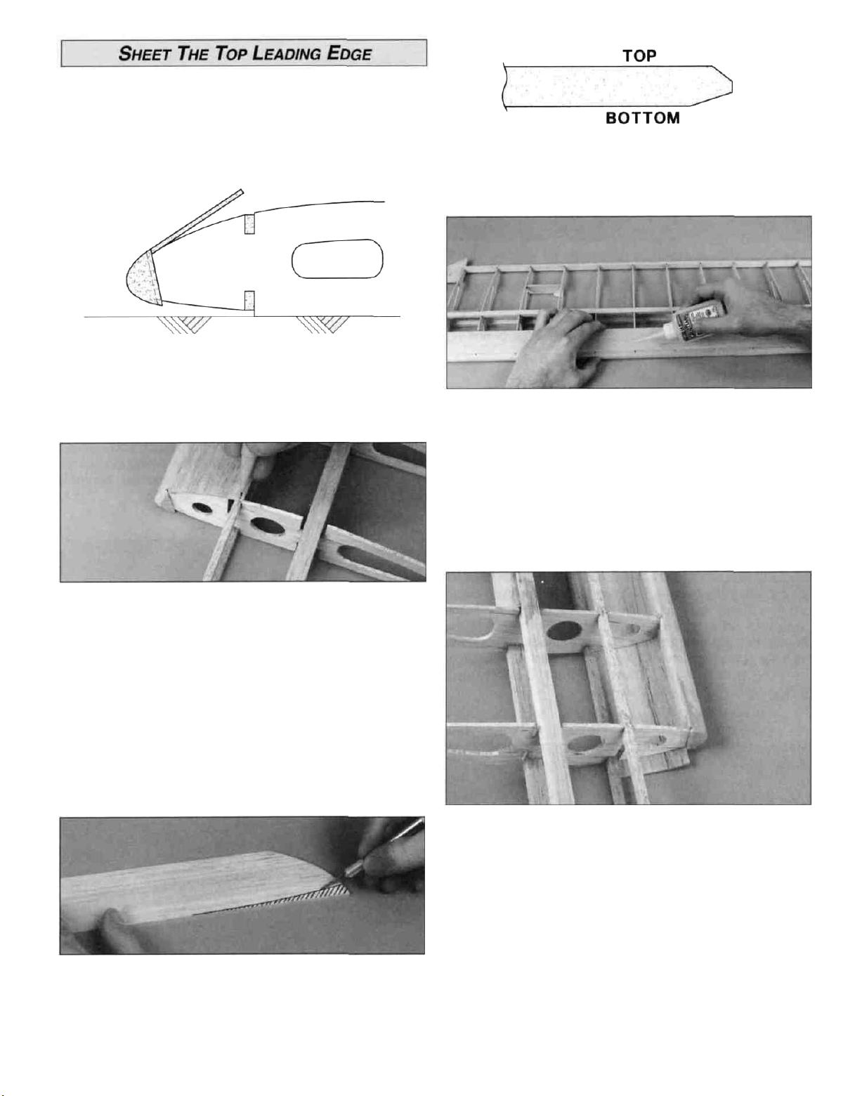
Sheet the top leading edge .....................................14
Sheet the bottom leading edge ...............................15
Joining the wing panels...........................................15
Sheet the center of the wing ...................................17
Wing completion .....................................................17
BUILD THE FUSELAGE ..............................................19
Build the fuselage sides..........................................19
Join the fuselage sides ...........................................20
Install the firewall ....................................................22
Install the engine ....................................................23
Sheet the nose & fuselage......................................24
Install pushrod tubes...............................................25
Install the stabilizer base.........................................25
Sheet the fuselage bottom ......................................26
Mount the wing on the fuselage..............................27
Mount the stab and fin ............................................28
Install the fuselage stringers ...................................28
Install the tail fairing ................................................30
Install the control horns...........................................30
Install the tail gear...................................................31
Install the main landing gear...................................31
Build and install the wing struts...............................32
Install the cowl
........................................................33
Scale details............................................................34
FINISHING........................................................................35
Final sanding...........................................................35
Balance the airplane laterally..................................35
Cover the structure with
MonoKote®
film
................35
Painting...................................................................36
Fuelproofing............................................................36
FINAL ASSEMBLY.......................................................36
Install the control surfaces ......................................37
Install the wheels ....................................................38
Install the windows..................................................39
Install the landing gear fairing .................................39
Radio installation.....................................................39
Balance your
model
................................................40
Finish
radio installation
...........................................41
Control surface throws ............................................42
Install the pilot.........................................................42
Preflight...................................................................43
Balance the propeller..............................................43
AMA Safety Code....................................................44
FLYING........................................................................44
Takeoff.....................................................................45
Flying ......................................................................45
Landing...................................................................45
Your Great Planes Piper J-3 Cub 20 is not a toy, but
rather a sophisticated, working model that functions very
much like an actual airplane.
Because of its realistic performance, the Cub 20, if not
assembled and operated correctly, could possibly cause
injury to yourself or spectators and damage property.
To make your R/C modeling experience totally
enjoyable, we recommend that you get experienced,
knowledgeable help with assembly and during your
first flights. You'll learn faster and avoid risking your model
before you're truly ready to solo. Your local hobby shop has
information about flying clubs in your area whose
membership includes qualified instructors.
You can also contact the national Academy of Model
Aeronautics (AMA), which has more than 2,300 chartered
clubs across the country. Through any one of them,
instructor training programs and insured newcomer training
are available.
Contact the AMA at the address or toll-free phone
number below.
Academy of Model Aeronautics
5151 East Memorial Drive
Muncie, IN 47302-9252
Toll Free (800) 435-9262
Fax# (317)741-0057
2
Page 3
Thank you for purchasing the Great Planes Piper J-3
Cub 20 for your next project We are sure that you will find
a great deal of modeling satisfaction while building and
flying this 1930's classic
You will find the J-3 Cub easy to build and fly, very
predictable and fairly acrobatic, yet it has no bad habits
Traditional Great Planes interlocking construction makes it
simple to build a great looking and straight airplane that is
sturdy enough to take along every time you go to the
flying field
If you have chosen this kit as your first R/C model, it is
important that you find an experienced modeler to help you
throughout the building and flying of this plane He should
thoroughly check the plane over before flying it and help
you with the first flights The J-3 Cub lacks the self-recovery
characteristics of a good basic trainer such as the Great
Planes PT Series airplanes On the other hand, if you have
already learned the basics of R/C flying and you are able to
safely handle a "trainer" airplane, the J-3 Cub is an
excellent choice to sharpen your skills and learn the art of
flying a taildragger So, dust off your work bench, put a new
blade in your hobby knife, load some fresh sandpaper and
let's build a 'J-3 Cub'
Please inspect all parts carefully before starting to
build! If any parts are missing, broken or defective, or if
you have any questions about building or flying this
model, please call us at (217) 398-8970 and we'll be
glad to help. If you are calling for replacement parts,
please look up the part numbers and the kit
identification number (stamped on the end of the
carton) and have them ready when calling.
6 You must fly the model only with the help of a
competent, experienced R/C pilot if you are not already
an experienced and knowledgeable R/C pilot at this time
Note: We, as the kit manufacturer, can provide you with
a top quality kit and great instructions, but ultimately the
quality and flyability of your finished model depends on
how you build it, therefore, we cannot in any way
guarantee the performance of your completed model,
and no representations are expressed or implied as to
the performance or safety of your completed model
Remember: Take your time and follow directions to end
up with a well-built model that is straight and true.
There are several engines that will work well in the Cub 20
For a relaxed flying experience, an 0 S 15FP is a good
choice For a more spirited model an 0 S 20- 25FP or
26 Surpass (4-stroke) will work very well Your choice of
2-stroke or 4-stroke engine will determine the location of
the throttle pushrod exit, so you must acquire the engine
early in the building process, and plan ahead.
Note Items in parentheses (GPMQ4130) are suggested
part numbers recognized by distributors and hobby shops
and are listed for your convenience GPM is the Great
Planes brand, HCA is the Hobbico® brand and TOP is the
Top Flite® brand
1 You must assemble the plane according to the plans and
instructions Do not alter or modify the model, as doing so
may result in an unsafe or unflyable model In a few cases
the plans and instructions may differ slightly from the
photos In those instances you should assume the written
instructions are correct
2 You must take time to build straight, true and strong.
3 You must use a proper R/C radio that is in first class
condition, the correct sized engine and correct
components (fuel tank, wheels, etc ) throughout your
building process
4. You must properly install all R/C and other components
so that the model operates properly on the ground and in
the
air.
5. You must test the operation of the model before the first
and each successive flight to insure that all equipment is
operating, and you must make certain that the model has
remained structurally sound Be sure to check the nylon
clevises often and replace if they show signs of wear
D 4 Channel radio with 4 servos
D Engine 15-25 2-stroke
20- 26 4-stroke
D Propeller (A Top Flite Power Point® is recommended,
see the engine instructions for size)
D 6oz Fuel Tank - (GPMQ4102)
D 12" Medium Fuel Tubing - (GPMQ4131)
D (2) 2-1/2" Main Wheels - (GPMQ4223)
D (1) 1" Tail Wheel - (GPMQ4241)
D (4) 5/32" Wheel Collars - (GPMQ4306)
D (2) 3/32" Wheel Collars - (GPMQ4302)
D (2) Rolls MonoKote® Cub Yellow
Covering - (TOPQ0220)
D 1/2" Latex Foam Rubber Padding - (HCAQ1050)
D Cub Yellow LustreKote® - (TOPR7220)
D 1/16" Black Striping Tape - (GPMQ1460)
D Fueling Valve - (optional GPMQ4150)
D Switch and Charge Jack Mount - (GPMM1000)
D Screw-Lock Pushrod Connectors - (GPMQ3870)
D Flexible Cable Pushrod for Throttle - (GPMQ3700)
D 2" Pilot Figure - (optional - Williams Bros #184)
3
Page 4
We recommend Great Planes Pro™ CA and Epoxy
D 2 oz Thin CA Adhesive - (GPMR6003)
D 2 oz Medium CA+ Adhesive - (GPMR6009)
D 1 oz. Thick CA- Adhesive - (GPMR6014)
D 6-Minute Epoxy - (GPMR6045)
D 30-Minute Epoxy - (GPMR6047)
D Pacer Formula 560 Canopy Glue
D Hand or Electric Drill
D Sealing Iron - (TOPR2100)
D Heat Gun - (TOPR2000)
D Hobby Saw - (X-acto® Razor Saw)
D Hobby Knife with #11 Blades
D Razor Plane - (Master Airscrew®)
D Screw Drivers - (Phillips and Slot tip)
D Flat File
D T-Pins Medium - (HCAR5150)
D String
D Straightedge with Scale
D Masking Tape - (required for construction)
D Sandpaper- (coarse, medium, fine grit)*
D T-Bar Sanding Block - (or similar)
D Lightweight Balsa Filler- (HCAR3401)
D #10-24 Tap and Tap Wrench
D IsopropyI Rubbing Alcohol - (70%)
D Dremel® Moto-Tool® or Similar - (optional)
D Kyosho® Curved Scissors (optional) - (KYOR1010)
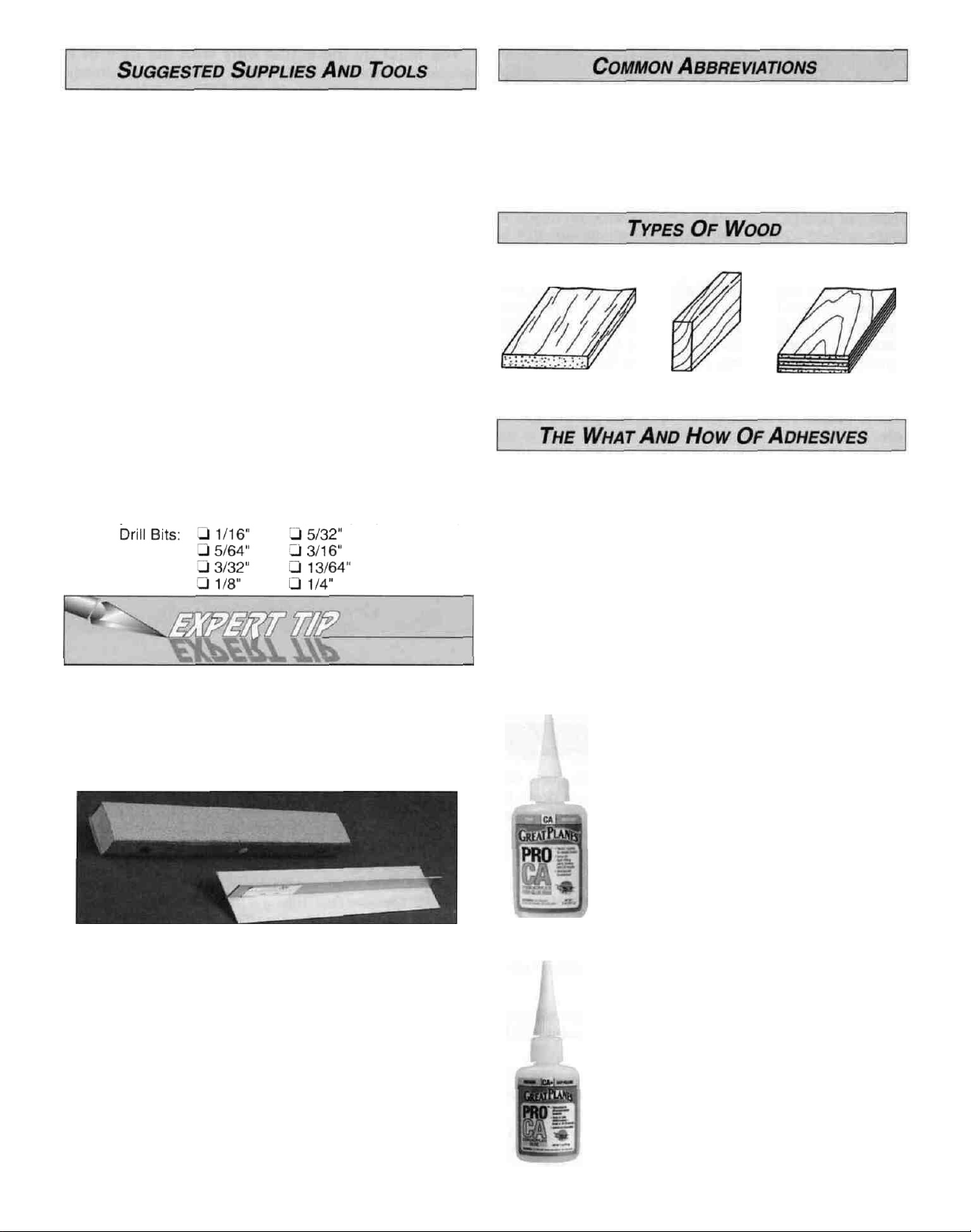
*0n our workbench, we have four 11" T-Bar sanders,
equipped with #50, #80, #150 and #220-gnt sandpaper
This setup is all that is required for almost any sanding
task Custom sanding blocks can be made from balsa
for sanding hard to reach spots We also keep some
#320-grit wet-or-dry sandpaper handy for finish sanding
before covering.
T-Bar sanding tools are made from lightweight extruded
aluminum and can be found at most hobby shops A
2" x 11" strip of sandpaper is attached to the T-Bar by
gluing it on with rubber cement. Apply the rubber
cement to both the bottom of the T-Bar and the back of
the sandpaper When both surfaces are dry, press the
sandpaper firmly onto the T-Bar Spray adhesive can be
used for this purpose but it's harder to remove the
sandpaper when you need to replace it Wooden
sanding blocks can be made from straight 11" lengths
of 1" x 2" scrap lumber Start on one side, then wrap a
sheet of sandpaper completely around the wood,
ending on the same side as the one you started on.
Push 3 or 4 thumbtacks into this side, then trim off the
excess material.
Elev = Elevator
LE = Leading Edge (front)
Ply = Plywood
TE = Trailing Edge (rear)
Fuse = Fuselage
LG = Landing Gear
Stab = Stabilizer
" = Inches
Balsa Basswood Plywood
Cyanoacrylate: or CA glue has changed the way models
are built more than any other advance in modeling
technology In the good ol' days, model cement like
Ambroid, Duco, Comet and Sigment were the glues of
choice They all had a strong odor that could cause
dizziness, dried slowly (compared to CA) and became
brittle with age CA, on the other hand, is stronger, works
almost instantly and is bottled in three different viscosities
(thicknesses) CA is used for most glue joints, except where
epoxy is specified CA does emit rather strong fumes (some
say it's like tear gas) as it cures, so rule number one is to
work in a well ventilated area. All CA glues work best if the
joints are smooth and fit well.
Thin CA is also known simply as CA This
is the adhesive that has revolutionized
model building because it allows you to
assemble the parts first, then apply the
adhesive The thin formulation flows or
"wicks" into the joints and sets almost
instantly, eliminating the need to use pins to
hold things together while the glue dries.
You will often use thin CA for the initial
bond, but then follow with medium or thick
CA for extra strength, especially when
gluing plywood or hardwood.
CA+ is also known as medium or gap
filling CA CA+ is used for surface gluing,
filling small gaps between poorly matched
parts and for general purpose applications.
It cures slower than thin CA, allowing you to
apply a bead to two or three parts before
assembly Curing time without accelerator is
20 - 30 seconds.
4
Page 5
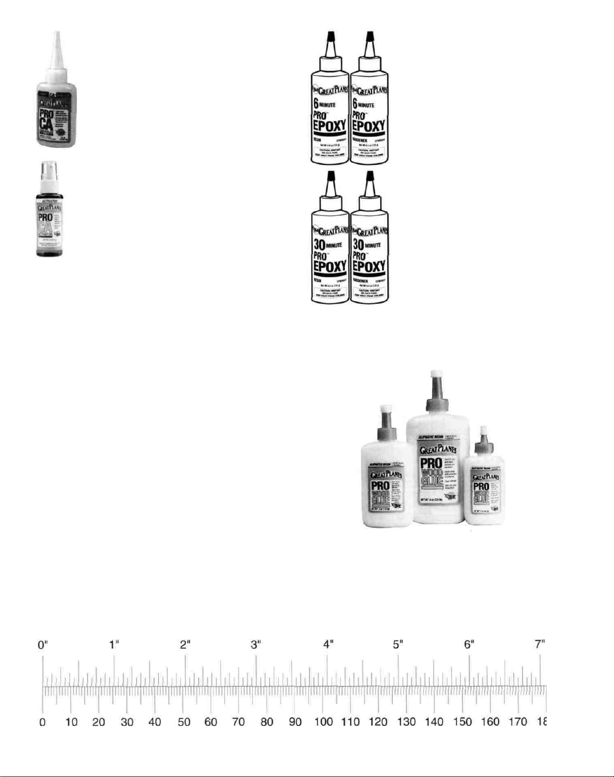
CA- or thick CA is used when extra positioning
time is needed CA- is a great gap filler and is
also used in conjunction with accelerator to
make fillets when a little extra strength is
required Curing time is about 1-2 minutes.
Accelerator is a liquid chemical that comes in a
spray bottle for use in speeding up the cure time
of all CA types It should be misted on, not
sprayed heavily on the joint Accelerator may
cause exposed CA to bubble and sometimes
change color If accelerator is sprayed on heavily
it may weaken the glue joint, so use it sparingly
A WORD ABOUT CA SAFETY
After applying CA, don't stand directly over the work, to
avoid the puff of vapors All CA glues will bond skin
almost immediately If this should happen, CA Debonder
(available from your hobby dealer) or acetone fingernail
polish remover will dissolve the CA if allowed to soak into
the bond for a few minutes Don't use vigorous means to
separate a skin bond Never, never point the CA
applicator tip toward your face' Be especially careful
when opening a clogged tip In case of eye contact, flush
thoroughly with water and then seek medical attention,
but don't panic. Please, keep CA (and all other
modeling chemicals) out of the reach of children!
6-Minute epoxy is used for simple,
small gluing operations where
elaborate alignment is not required.
Working time (before it's too gooey to
use) is about 5 minutes, handling
time 15 minutes, and it's fully cured
in about 1 hour
30-minute epoxy is used for extra
strength (because it can penetrate
longer) and where several parts must
be aligned and checked before it
cures Working time is about 25
minutes, handling time 2 hours, and
it's fully cured in 8 hours.
Epoxy:
Great Planes has two Epoxy formulations available for the
modeler Both offer exceptional strength and convenient
working times Use epoxy when the joint requires exceptional
strength, such as when installing the firewall, when joining
the wing panels and when installing wing hold-down blocks
As with most epoxies, you mix equal parts of resin and
hardener, stir well, then apply a thin film to each part Parts
should be clamped, pinned, taped or weighted in place until
fully cured Before the epoxy cures, clean off any excess with
a paper towel A word of caution about mixing epoxy — don't
use extra hardener in the hopes of making the mixture
harder or work faster Just about all epoxies work best with
exactly a 50/50 mix When you increase the amount of
hardener you run the risk of causing the cured epoxy to
become either brittle or rubbery — neither being as strong as
a properly mixed batch.
Inch Scale
Great Planes Pro Wood Glue is an aliphatic resin glue
that works well on all types of wood It is non-toxic, virtually
odorless, and dries clear Some people are sensitive to CA
and epoxy fumes, so this is a good alternative for general
modeling use Its only drawback is that it is slow to cure,
requiring the parts to be securely clamped, pinned, or taped
while the glue dries
Metric Scale
5
Page 6
6
Page 7
Inches x 25.4 = mm (conversion factor)
1 /64" = .4mm 3/4" = 19.0mm
1/32" = .8mm 1" = 25.4mm
1/16"= 1.6mm 2" = 50.8mm
3/32" = 2.4mm 3" = 76.2mm
1/8" = 3.2mm 6" = 152.4mm
5/32" = 4.0mm 12" = 304.8mm
3/16" = 4.8mm 18" = 457.2mm
1/4"= 6.4mm 21"= 533.4mm
3/8" = 9.5mm 24" = 609.6mm
1/2" = 12.7mm 30" = 762.0mm
5/8" = 15.9mm 36" = 914.4mm
D 1. Unroll the plan sheets. Reroll the plans inside out to
make them lie flat.
D 2. Remove all parts from the box. As you do, determine
the name of each part by comparing it with the plans and
the parts list included in this kit. Using a felt tip pen or ball
point pen, write the part name or size on each piece to
avoid confusion later. Use the die-cut patterns shown on
page 6 to identify the die-cut parts and mark them before
removing them from the sheet. Save all scraps. If any of the
die-cut parts are difficult to punch out, do not force them!
Instead, cut around the parts with a hobby knife.
After punching out the die-cut parts, use your T-Bar or
sanding block to lightly sand the edges to remove any
die-cutting irregularities.
Tape the plan to a flat building surface, then cover the fin
and rudder section with waxed paper. Refer to the plan to
identify the parts and their locations.
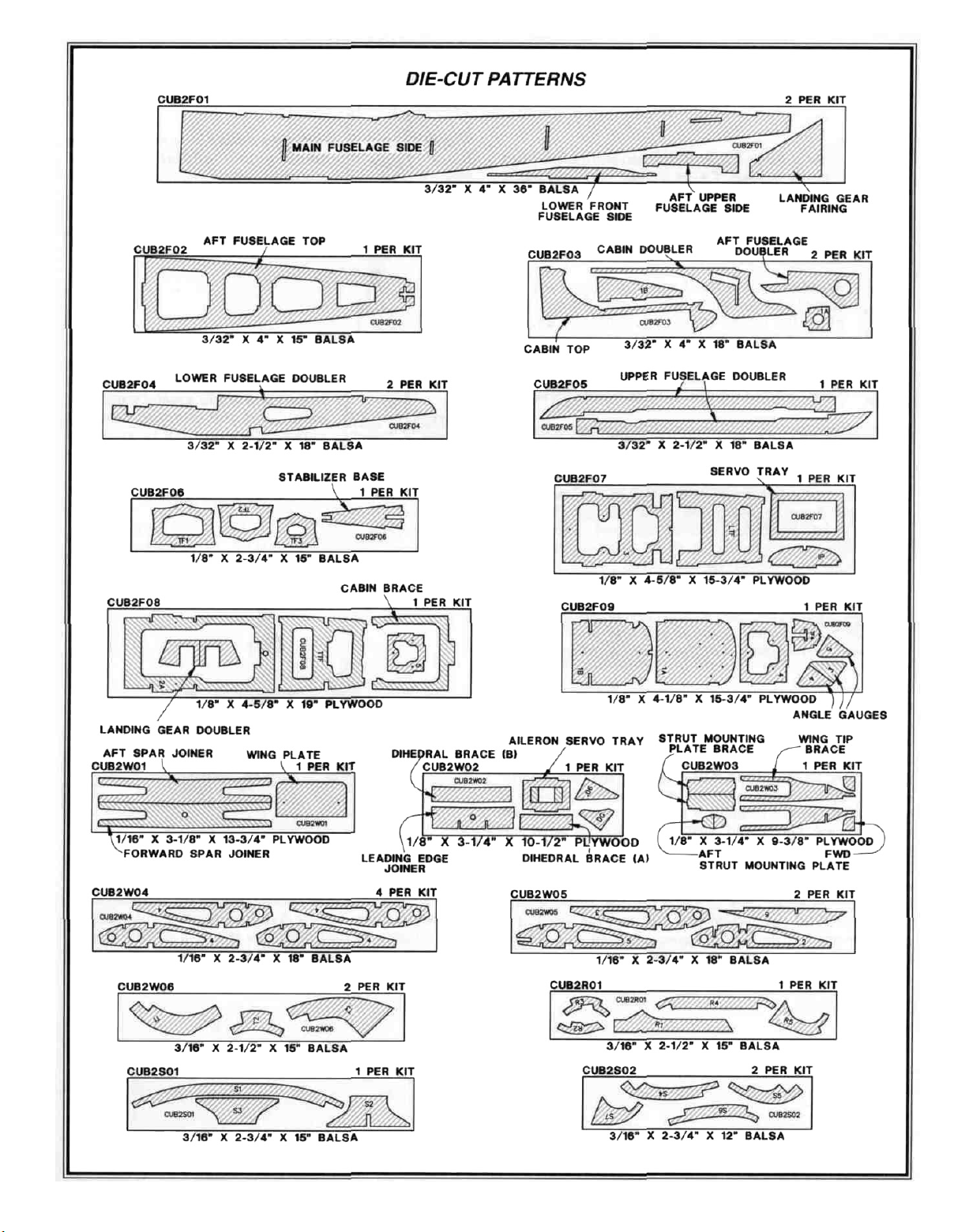
D 1. Place the die-cut 3/16" balsa rudder parts R2, R3, R4
and R5 over the plan in their locations. Check their fit and
sand the mating edges as needed. Use a T-bar or other flat
sanding block to make any necessary adjustments. Pin the
parts to the building board after proper alignment and fitting
has been done. Do not glue the parts together at this time.
D 2. Select the straightest piece from the four
3/16" x 5/8" x 18" balsa sticks. Set this piece aside for use
later on the stabilizer trailing edge.
D 3. As you identify and mark the parts, separate them into
groups, such as fuse (fuselage), wing, fin and stab
(stabilizer) and hardware.
IMPORTANT: For a model that flies well with no
unexpected tendencies, all good modelers understand that
each assembly, especially the wing, must be built on a flat
surface. Also, a relatively soft, flat building board that you
can stick "T" pins into is required. This is for pinning down
individual parts during construction. A suitable building
board is a sheet of "Celotex" used in home construction.
This material may be found at hardware or home
improvement stores. If the building board is not flat, it must
be clamped to your flat building table. Now we're ready
to begin!
Okay, you've got your work space ready, your tools are
at hand and you know how to choose and use the right
glue for the job. Let's get started!
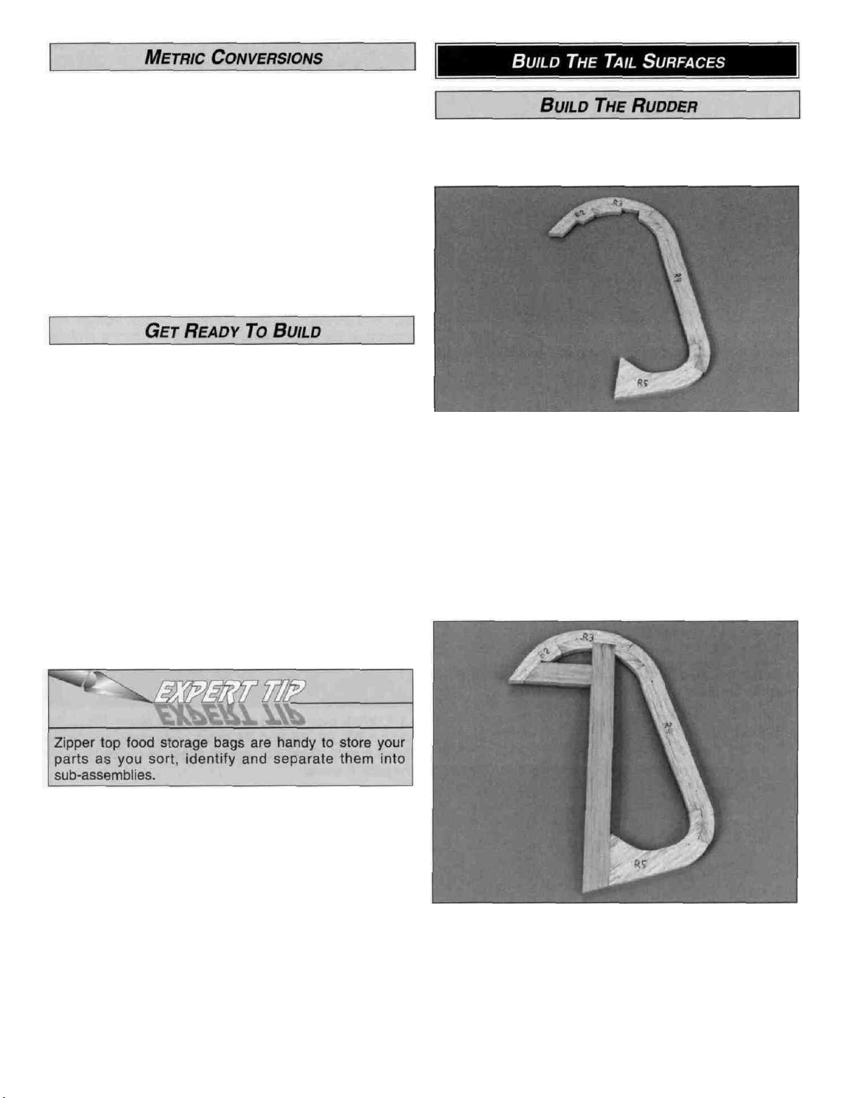
D 3. Cut the rudder LE from another 3/16" x 5/8" x 18"
balsa stick. Fit the LE into the notch in R3 and against the
edge of R5. Cut the horizontal frame section from the
3/16" x 5/8" x 18" left over from the rudder leading edge,
and fit it in position. Pin the LE and horizontal frame section
in place and glue all the parts together with thin CA. Wipe
off any excess glue from the surface before it cures.
NOTE: Leave all the parts pinned to the building board.
7
Page 8
D 4. Cut the ribs from the 3/16" x 3/16" x 24" balsa stick.
Position the ribs in the rudder frame and glue them in place
with thin CA.
D 5. Remove the rudder from the building board and
inspect all the glue joints. Add thick CA to any open joints.
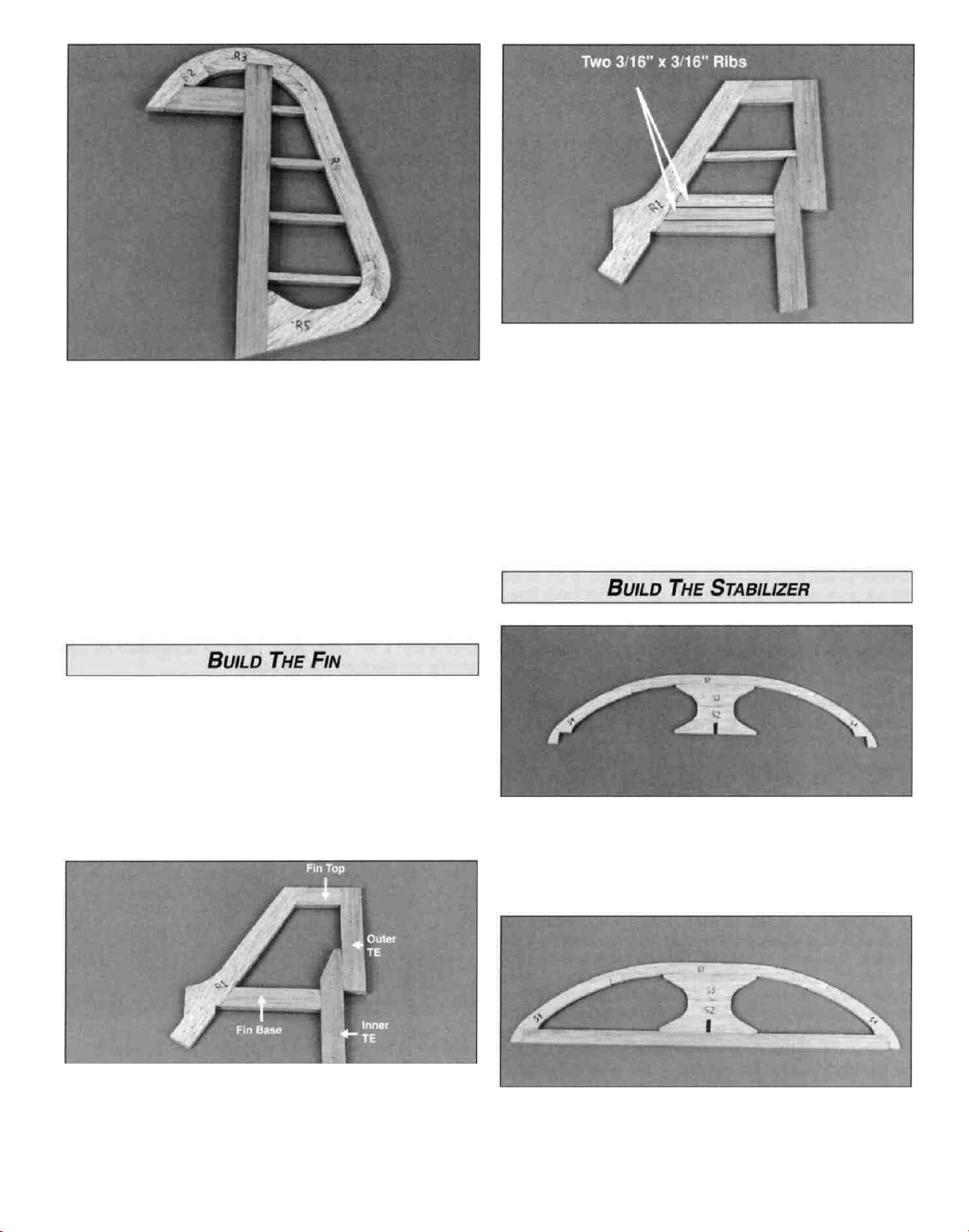
D 1. Pin the die-cut 3/16" balsa fin leading edge R1 in
place on the plan.
D 3. Cut the three ribs from the 3/16" x 3/16" x 24" balsa
stick to fit between the forward and aft frames. Position two
ribs above the lower frame for additional bracing and the
third rib at the location shown on the plan. Glue the ribs to
the frame with thin CA.
D 4. Remove the fin from the building board and inspect all
the glue joints. Apply thick CA where necessary.
D 2. Cut the fin top, fin base and the inner and outer fin
TE from the remaining 3/16" x 5/8" x 18" balsa sticks.
Check the fit and sand their mating edges as needed. Pin
the parts in place, then glue them together with thin CA.
NOTE: Leave all the parts pinned to the building board.
D 1. Work over waxed paper covered plans. Place the
die-cut S1, S2, S3 and S4 balsa parts over the plan to
check their fit. Sand their mating edges as needed and pin
the parts in place.
D 2. Cut the Stabilizer TE from the 3/16" X 5/8" X 18"
balsa stick you set aside earlier. Fit the TE between the S4
parts on the plans. Glue all the parts together with thin CA.
NOTE: Leave the parts pinned to the building board.
8
Page 9
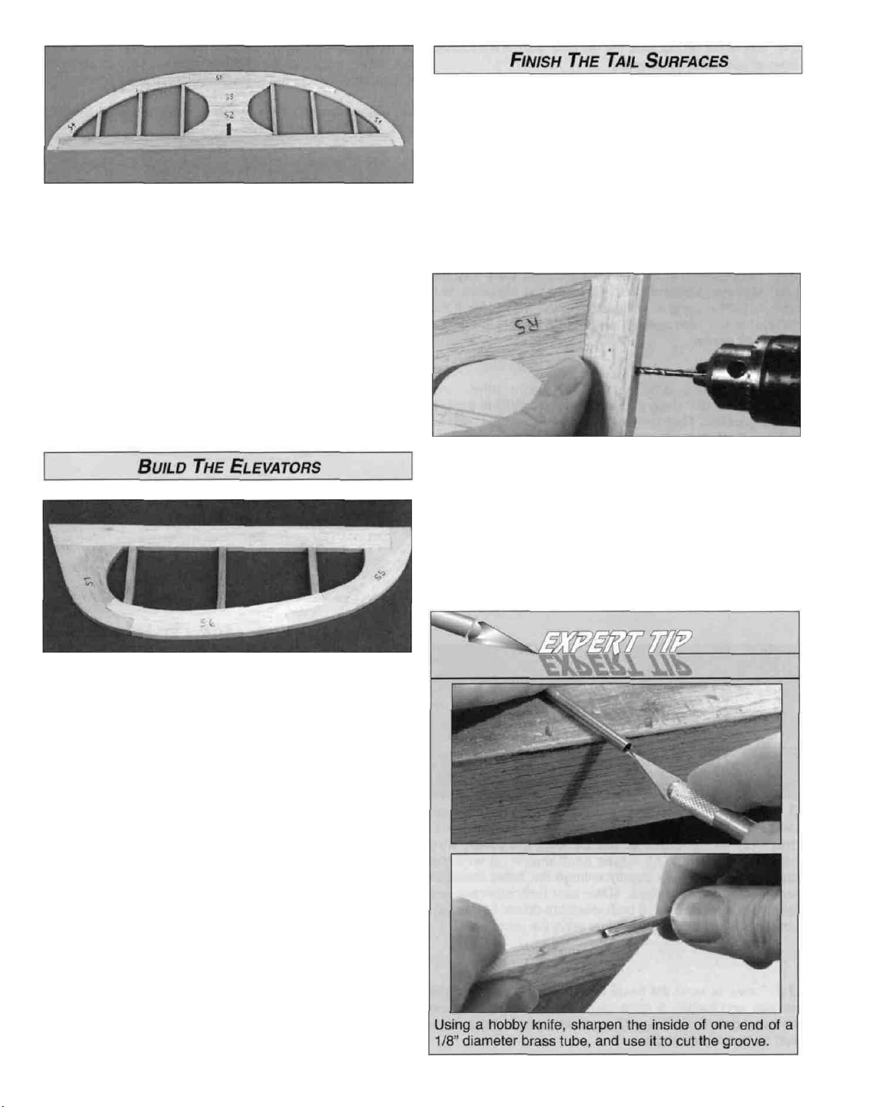
D 3. Refer to the plan, then cut six ribs from the
3/16" x 3/16" x 24" balsa stick. Position the ribs in the
stabilizer frame and glue in place with thin CA.
D 4. Remove the stabilizer from the building board and
inspect all of the glue joints. Apply thick CA to any
open joints.
D 1. Carefully sand all the tail surfaces flat with 150-grit
sandpaper and a large sanding block or T-bar. Remove as
little material as possible and don't get carried
away - inspect your work as you proceed. It's easy to
sand a low spot into the ribs or trailing edge, so be
careful to avoid doing this.
D 2. Draw centerlines around the outside edges of the fin,
rudder, stabilizer and elevator to assist in sanding and
hinge installation.
D 3. Position the rudder over the plan and align the bent
wire tail gear over the bottom end of the rudder as shown.
Mark the tail gear "arm" location on the centerline of the
rudder LE. Drill a 7/64" hole, 3/4" deep at this spot (the hole
is drilled slightly oversize to create a hard epoxy "sleeve"
around the wire). Cut a groove from the tail gear hole to
the bottom of the rudder that will allow the nylon tail gear
bearing to fit flush with the LE of the rudder. Do not glue
the tail gear in at this time.
D D 1. Position the S5, S6 and S7 from the die-cut 3/16"
balsa parts over the plan and check the fit of the mating
edges and sand them as needed. Cut the elevator LE from
a 3/16" x 5/8" x 24" balsa stick. Pin the parts in place over
the plans and glue them together with thin CA.
D D 2. Refer to the plan, then cut three elevator ribs from
the 3/16" x 3/16" x 24" balsa stick. Position and glue the
ribs in the elevator frame with thin CA.
D D 3. Remove the elevator from the building board and
inspect all the glue joints. Apply thick CA to any open joints.
D 4. Repeat this process to build the other elevator.
9
Page 10
D 4 Trial fit but do not glue the tail gear wire in the rudder.
Make adjustments if necessary.
D 5 Temporarily pin the elevators on the plan Lay the
3/32" elevator joiner wire in place on the elevators and
mark its outline using a soft leaded pencil NOTE: Mark the
elevator joiner wire outline very lightly so that it can be
sanded off easily
D 6 Accurately drill a 1/16" diameter pilot hole
approximately 3/4" deep and perpendicular (90°) to the LE,
at each location Then drill the final hole with a 7/64" drill bit
to a depth of 7/8" (The hole is drilled slightly oversize to
allow for positioning, and to allow room to create a hard
epoxy "sleeve" around the wire).
D 7 Use your sharpened 1/8" diameter brass tube to cut a
groove in the leading edge of both elevators to accept the
elevator joiner wire Slightly round the inside corner where
the groove meets the hole to allow for the bend in the
elevator joiner wire.
D 10 Sand the leading edges of the stabilizer and fin and
the trailing edges of the elevator and rudder to a rounded
shape, as shown in the cross-section on the plan.
We have found that it's much simpler to do all hinging
after the model is covered.
D 1 Build one wing "half" or panel at a time You may want
to cut out each wing panel from the plan sheet to place on
your building board Tape the plan to your flat building
board and cover it with waxed paper Begin with the right
wing panel.
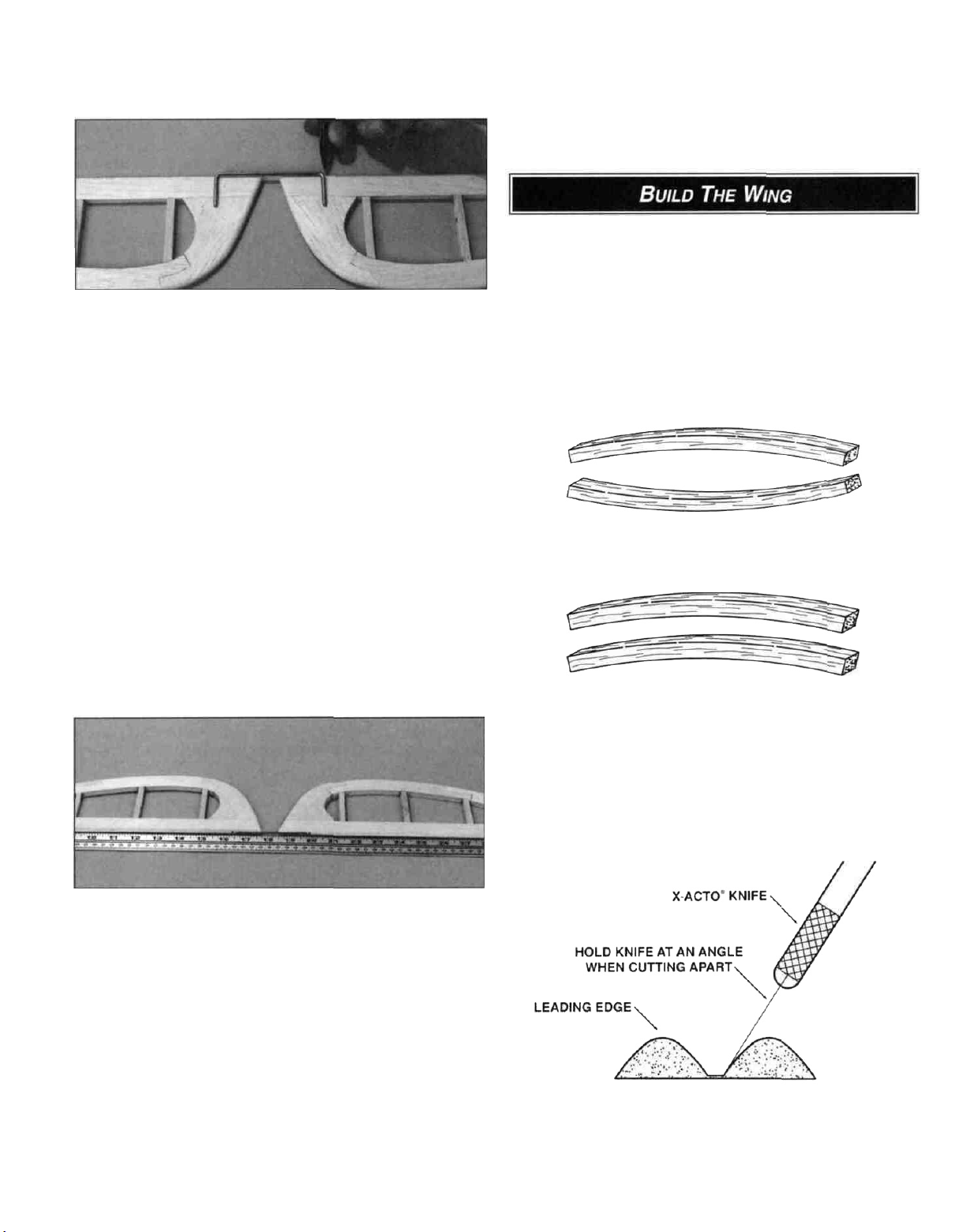
TWO WARPED SPARS INSTALLED
THIS WAY WILL RESULT IN A
STRAIGHT WING
TWO WARPED SPARS INSTALLED
THIS WAY WILL RESULT IN A
WARPED WING
D 8. Test fit (do not glue yet) the joiner wire into both
elevators Position the elevators against a straightedge to
check for straightness of the LE with the joiner wire
installed If the leading edges don't match up with the
straightedge, you may slightly enlarge the holes drilled in
the elevator leading edges Make sure both elevators are
flat on the work surface If both elevators do not lie flat, you
can make slight adjustments by twisting the joiner wire.
D 9. Carve or sand the bevel on the leading edges of the
elevator and rudder A razor plane allows you to rough-in
the bevel before finishing with a sanding block Refer to the
plan for the correct angle
D 2. Locate all four 1/4" x 5/16" x 27" balsa spars and
examine them carefully for possible imperfections Look for
knots, soft spots, diagonal grain and any other
imperfections If possible, position each spar so the
imperfections are on the outer half of the wing panel
(toward the tip), where they will be least affected by high
stress If the spars are warped slightly try to "balance them
out" by installing the warped spars in opposite directions
(see sketch above).
D 3. The shaped and notched wing leading edges (LE)
and trailing edges (TE) are fastened together by thin strips
of balsa Separate them by cutting with a hobby knife, as
shown in the sketch above
10
Page 11
D 4. Carefully remove all the die-cut 1/16" balsa R1
through R6 wing ribs from the die-cut sheets. Sand the
edges slightly to remove any die-cutting irregularities.
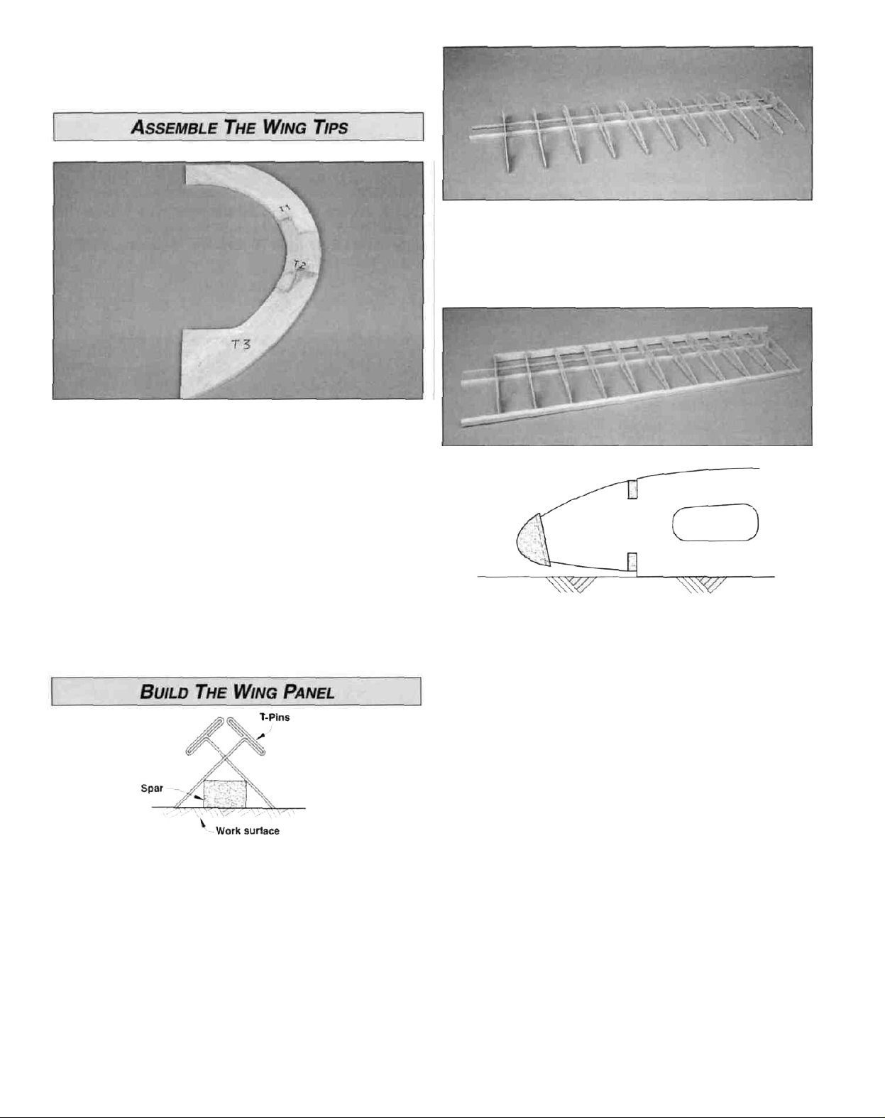
D D 1. Place the die-cut 3/16" balsa wing tip parts T1,T2
and T3 over the plan and check all joints for proper fit.
Make adjustments if necessary. Pin the parts over the plan
and glue them together with thin CA.
D D 2. Without gluing, place ribs R2 through R5 on the
spars in their locations as shown on the plans.
D D 2. Remove the wing tip from the building board and
inspect all glue joints. Apply thick CA to any open joints.
D D 3. Place the wing tip on your work surface and lightly
sand both sides smooth with 80-grit sandpaper. Set the
wing tip aside for now.
D Repeat steps 1 -3 for the other tip.
D D 1. Do not use any glue until step five. For now,
we're just making preparations and familiarizing
ourselves with the layout. Place one of the 1/4" x 5/16" x
27" balsa lower main spars and one of the 1/8" x 3/16" x
27" balsa lower forward spars on the wing plan. Pin only
the main spar down with crossed T-pins as shown in the
sketch. We recommend crossed T-pins at every rib bay (the
space between the ribs). The lower forward spar is for
alignment at this point and will be glued to the ribs later.
NOTE: Align the end of the spars with the outboard edge of
the wing rib R5. Leave the spars' "overhang" at the root
(inboard end) of the wing. We'll trim it off later before joining
the wing halves,
D D 3. Match the notches in the shaped balsa LE and TE
with the plan. Add the LE and TE to the ribs making sure
each rib is fitted into its respective notch. Center the LE
vertically so there is an equal amount of space above and
below each rib.
D D 4. Pin the TE to the building board. Place a piece of
scrap 1/16" balsa sheet under ribs R2 and R3 at the TE to
center them in the TE. Check that ribs, R4 and R5 are
against the building board.
D D 5. Use a small building square or draftsman's triangle
to make sure each rib is vertical to the main spar. Glue the
ribs to the main spar with thin CA.
D D 6. Adjust the LE up or down until all the ribs are
centered in the notches in the LE. Note that the LE is
angled down slightly as shown in the cross section on the
plan. Apply thin CA to each joint between the ribs and
the
LE
and
TE.
11
Page 12
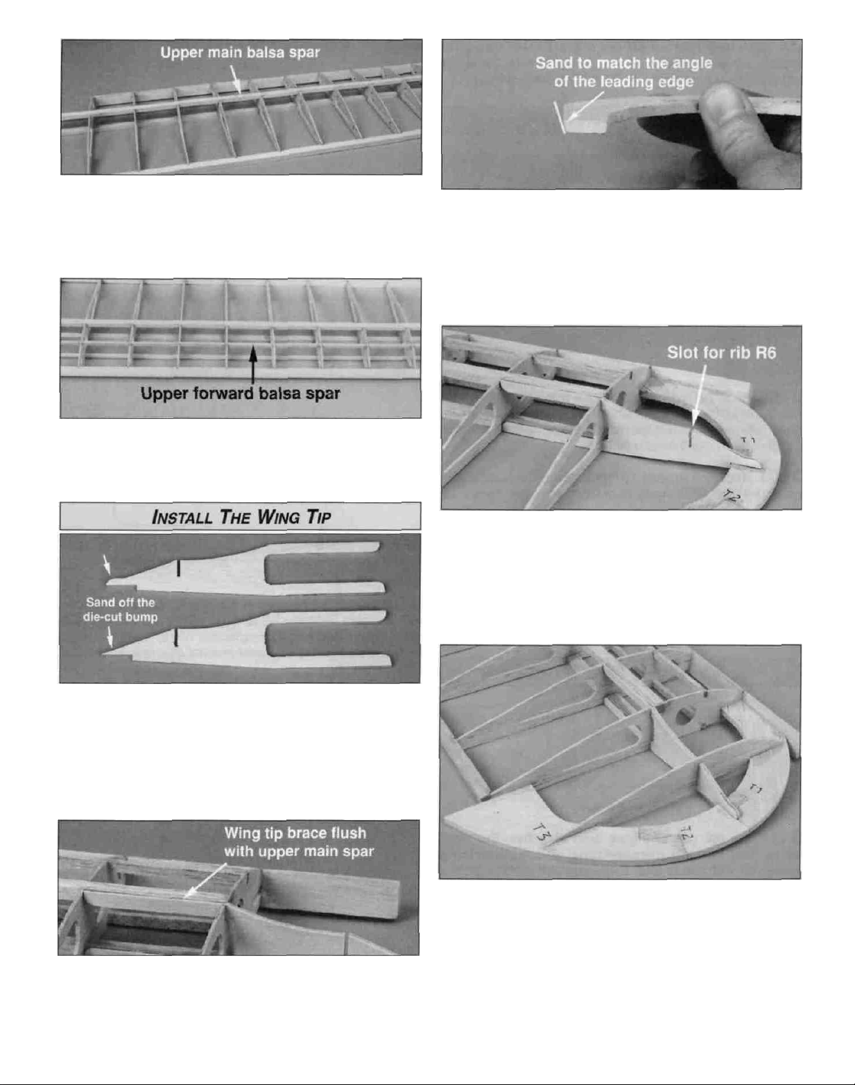
D D 7. Install the 1/4" x 5/16" x 27" upper main spar in
the wing ribs. Check that the top of the main spar is flush
with the top of the ribs. Make sure the end of the upper
main spar is flush with the outboard edge of rib R5. Glue
the main spar to the ribs with thin CA.
D D 8. Install the 1/8" x 3/16" x 27" upper forward balsa
spar in the wing ribs with one end of the spar flush with the
outboard edge of rib R5. Glue the forward balsa spar to
the ribs with thin CA.
D D 3. So that the wing tip can fit properly between the
LE and rib R5, sand the front of the wing tip to match the
angle of the LE. Trim the TE flush with R5 so you can fit the
tip properly in place.
D D 4. Insert the front of the wing tip into the slot in rib
R5. The aft end of the wing tip is attached to the TE of
the wing and the side of rib R5, while lying flush on the
building board.
D D 1. Locate the die-cut 1/8" plywood wing tip brace, the
die-cut 1/16" balsa wing tip rib R6, and your previously
assembled wing tip. Notice the plywood wing tip brace has
a small "die-cut bump" at the tip. This is to allow you to
finish the piece to a perfect point where the die-cutter may
have difficulty in this area. Take a minute to sand off the
bump so the profile continues along the intended outline.
D D 2. Fit the 1/8" plywood wing tip brace into rib R5. The
top "arm" on the wing tip brace should be flush with the top
of the upper main spar and the slot for rib R6 should be
over the rib location on the plans.
D D 5. Insert rib R6 in the slot in the plywood wing
tip brace.
D D 6. Check the fit of all the wing tip parts and sand any
mating edges as needed. Glue the wing tip parts together
and to the wing panel with thin CA.
12
Page 13
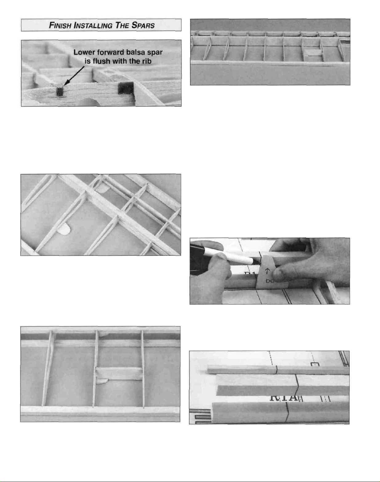
D D 1. Carefully remove the wing from the building board.
Turn the wing upside down. Press the balsa lower forward
spar into the notches in the ribs. Note that the front edge of
the notches in ribs R4 and R5 is 1/16" below the aft edge of
the notch. The lower forward spar should be flush with the
front edge of the notch and flush with the edge of ribs R2
and R3. Glue in place with thin CA.
D D 2. Carefully remove the wing from the building board
and turn it right side up. Align the spars and ribs with the
plans and pin it back on the building board. Test fit the
die-cut 1/8" ply forward and aft strut mounting plates to
the wing at the locations shown on the plans. Glue them to
the wing with thin CA. Then use thick CA to form a
reinforcing fillet at the glue joint.
D D 4. Glue eight 1/16" x 2-3/8" x 1-3/16" balsa vertical
grain shear webs to the rear of the balsa main spars
starting between ribs R3 and R4 and ending between the
last two R4 ribs. Shear webs will be installed between ribs
R2 and R3 after the wing halves are joined. The shear
webs are provided slightly thinner than the wing so they
may be positioned without protruding above or below the
top and bottom spars. It is not necessary to glue the shear
webs to the ribs - but, it is important to glue the shear
webs securely to the spars.
Note: At this point the wing should still be pinned to the
work surface. Of course, we cannot add shear webs if the
crossed T-pins are in position so remove the T-pins as you
go. Then replace the T-pins through the sheer webs in
order to keep the wing flat on your building board - or, use
weights on top of the wing instead of the T-pins to hold the
wing flat as you glue the shear webs in position. You only
need to replace T-pins at every other rib bay.
D D 5. Locate the 1/8" die-cut plywood dihedral gauge
(DG). Hold the gauge next to the main spar with the corner
of the gauge at the wing centerline on the plan. Mark both
sides of the main spars using the (DG) as shown in
the photo.
D D 3. Test fit the die-cut 1/8" ply strut mounting plate
brace over the aft strut mounting plate. Make sure the
brace contacts the wing ribs and the strut mounting plate.
Glue the brace with thin CA, followed by a fillet of thick CA
on all three pieces.
D D 6. Connect both lines by drawing a line across the top
of each spar.
D D 7. Follow the same procedure for the forward spars
and TE.
13
Page 14
D D 1. Use a T-bar or flat sanding block with 150-grit
sandpaper to lightly sand the top edges of the ribs to
smoothly blend the ribs to the main spar and remove
any bumps.
D D 2. Butt one of the 1/16" x 1-1/2" x 30" balsa wing LE
sheets against the leading edge. For the strongest glue
joint, sand or cut a bevel at the front edge of the sheet to
match the angle between the leading edge and the ribs.
D D 6. To provide a gluing surface for the sheeting, carve
a slight bevel on the wing tip where the sheet will meet
the
tip.
D D 7. Position the leading edge sheeting against the rear
edge of the LE and covering rib R2. Using thin CA, glue the
front edge of the sheet to the LE. Slightly wet the entire
sheet to bend it to the spar. Apply a bead of thick CA to the
forward spar. Working quickly, bend the sheeting to the
spar holding it down with something flat like a T-bar sander
or flat block of wood until the CA cures. Do not glue the
sheet to the LE past rib R5.
D D 3. Mark the sheet so that its aft edge is 1/16" ahead of
the aft edge of the top forward balsa spar. The exposed
spar will provide a "step" for the cap strips to glue to later.
D D 4. Before attempting to bend the sheet so it may
reach the outer wing tip, the sheet must be thoroughly
wetted from R5 outward. Use a spray bottle or a sponge
to liberally apply water to the tip area of the sheet outboard
of rib R5. Carefully "work" the sheet with your fingers by
bending and twisting it in the direction required to meet the
wing tip. Replace the sheet on the wing and test bending
the sheet into position. Don't force the sheet - add more
water if necessary.
D D 5. Starting at rib R5 the aft edge of the sheeting will
have to be trimmed to keep it parallel with the front spar
(notice that the sheeting bends backward as it is curved to
meet the tip). Trim and test fit the sheet until it conforms to
the desired straight line.
D D 8. Lift the wing off the building board. Wick thin CA
between the ribs and the sheet from the inside of the wing.
Add a fillet of medium or thick CA along the inside of
the
LE.
D D 9. Wet the sheet one more time in the tip area - the
water may have evaporated from the balsa. Test bend the
sheet to the tip. Apply thick CA where the sheet will contact
the outer tip. Add thin CA to the joint between the sheet
and rib R6. Fill the small seam between the LE and the
front of the sheet between ribs R5 and R6 with a scrap
piece of balsa.
14
Page 15
D D 9. Trim off some of the excess sheet past the wing tip
to allow the bottom sheet to make contact with the wing tip.
D D 1. Turn the wing over and install another
1/16" x 1-1/2" x 30" balsa wing LE sheet almost the same
way you installed the top except cut the sheet so it goes to
the aft edge of the forward spar. This time apply thick CA to
the ribs before you add the sheet.
time. It's easier to remove material than it is to add it.
Now that the right wing panel is completed, dust off your
building board and build the left wing panel.
D 1. Locate the die-cut 1/8" birch plywood dihedral brace
(A) and the die-cut 1/8" birch plywood dihedral brace (B).
Measure and draw a vertical centerline on both dihedral
braces. Glue the two dihedral braces together with
30-minute epoxy, lining up the centerlines. Clamp the
braces together and remove any excess epoxy with a
paper towel moistened with rubbing alcohol. While the
epoxy is curing, move onto the next step.
D D 2. Notice on the plan that the LE does not begin to
curve back until outboard of rib R5. Refer to the plan for
the correct shape. A razor plane works well to cleanly
remove material until you get close enough to use
sandpaper. Be careful with the razor plane - take a little
off at a time. Then use 150-grit sandpaper to rough sand
the wing tip to shape.
D D 3. Use a razor saw to cut both forward spars,
both main spars, and the TE on the lines previously drawn.
(See steps 5-7 on page 13).
D D 4. Sand the end of the spars and the trailing edge up
to the lines. Remove only a small amount of material at a
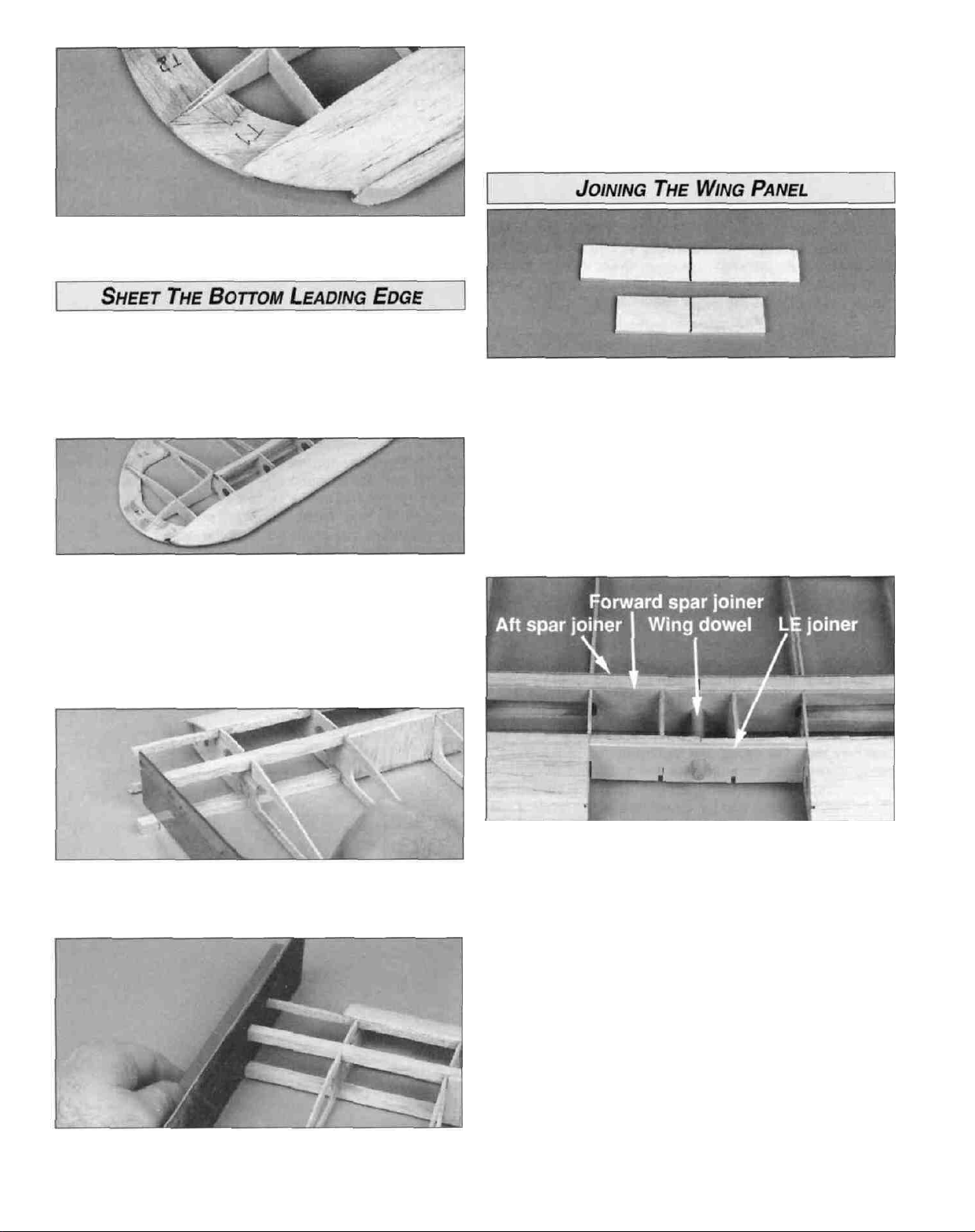
D 2. Without using glue, temporarily join the wing halves
using the die-cut 1/16" birch ply forward and aft spar
joiners and the die-cut 1/8" LE joiner. Also test fit the
die-cut 3/32" balsa sub ribs 1A in front of the forward spar
joiner. You may trim the ends of the forward and aft spar
joiners, but the LE joiner determines the width of the center
section and this should not be changed. With one of the
wing panels lying flat on your work table, prop up rib R5 of
the other panel 15/16" to account for the dihedral. Check
the fit of the spars, joiners and TE. At this time test fit the
1/4" x 1-3/4" wing dowel to check that it is perpendicular to
the leading edge joiner when fully seated into the forward
spar joiner. If you have to make adjustments here, do not
modify the LE joiner but adjust the position of the wing
dowel hole in the front spar joiner instead. Make sure you
have not built any "sweep" into the wing by making the
spars or TE too long or too short. Be sure to maintain the
correct spacing between ribs R2 per the plan so the wing
will fit on the fuselage.
15
Page 16

D 3. After the epoxy on the dihedral brace has cured, trial
fit the brace between the main spars. The dihedral brace
should fit snugly between the main spars without forcing
them apart. Sand the dihedral brace as necessary, being
careful not to change the angle of the brace.
D 4. 30-minute epoxy must be used for this step. Place
waxed paper on your work surface and mix up at least
1/2oz. of 30-minute epoxy. Apply the epoxy to all mating
surfaces of the forward and aft spar joiner, leading edge
joiner, main spars, dihedral brace and trailing edge.
Slide all the parts together and wipe off any excess epoxy
with a paper towel. Lay one wing panel flat on the work
table and block up the other wing panel 15/16" at rib R5.
Carefully align the spars and trailing edges of the panels,
being careful not to build in a twist. Clamp everything
together and wipe off any excess epoxy. Remove any
epoxy that squeezes into the dowel hole of the forward spar
joiner. Allow the epoxy to fully cure before removing the
clamps and disturbing the wing.
between ribs R2 and R3. Important: the bottom center
sheeting does not cover the main spar but butts up against
the spar joiners in front of, and behind the spar. Therefore,
the 1/16" shear webs must be positioned so that they are
about 1/16" lower than the edge of the spar joiners.
D 7. Without gluing, install both 3/32" die-cut balsa sub
ribs 1A and 1B between ribs R2. Place the aileron servo
tray in the notches in ribs 1B to produce the proper spacing
between the ribs. Note: Keep the plywood aileron servo
tray doublers you removed from the center of the aileron
servo tray. They will be used during radio installation. Also,
check that the 1B ribs are centered vertically in the slots in
the TE and 1/16" below the main spar and spar joiners.
Glue ribs 1A, 1B and the aileron servo tray in position with
thin CA. Turn the wing over a apply a fillet with thick CA at
the joints of the 1B ribs, the aft spar joiner and the aileron
servo tray.
D 5. Remove the wing from the building board and take off
all of the clamps. Sand off any excess epoxy that may
interfere with final assembly (wing sheeting, shear webs).
D 6. Add the four remaining 1/16" balsa vertical grain
shear webs - one in front and one behind the joiners
D 8. Round off one end of the 1/4" hardwood wing dowel
and slightly chamfer the other end of the dowel. Remove
any hardened epoxy that may be remaining in the hole in
the forward spar joiner with a round file. Install the dowel
with 6-minute epoxy. Wipe off any excess epoxy around the
front of the dowel with alcohol and a paper towel.
16
Page 17

D 1. Once more, look for any excess epoxy that will
interfere with the center section wing sheeting. Sand or cut
any excess epoxy off.
D 2. Locate the three pieces of 1/16" x 2-1/2" x 24" balsa
center section wing sheeting. Cut them into six
9-1/2" lengths.
D 3. Sheet the bottom of the wing first. Begin with the rear
sheet, then add the middle section, then the front. Also,
the bottom sheeting does not cover the main spar, but is
flush with it. Mark the location of the aileron servo tray on
the rear and middle sheets. Trim the sheets to blend into
the aileron servo tray. Add a strip of 1/16" balsa scrap
over the forward spars and the plywood LE joiner.
D 6. From the 1/16" x 3/16" x 24" balsa sticks, cut, then
glue the cap strips to the top of all R4 and R5 ribs with
medium CA. These cap strips run from the leading edge
sheeting to the TE.
D 7. Lightly mark a centerline from the TE toward the LE
on the top sheeting of the wing.
D D 1. Position the tapered and grooved 1-1/8" x 3-3/8"
hardwood wing center TE pieces over the plans and mark
the location of the aileron torque rod exits. Cut a notch in
the bottom forward edge of both pieces as shown in
the photo.
D 4. Sheet the top center section. Again, sheet the rear
section first, then the middle, then the front. The seam
between the front and middle section sheeting should be
made over the main spar. Like the bottom, add a strip of
1/16" balsa scrap over the forward spars and plywood
leading edge joiner.
D 5. After both the top and bottom sheeting is installed,
use a T-bar or sanding block to even the edges of the
sheeting 1/8" past the R3 ribs.
D D 2. Sand a slight angle on the inboard edge of the
wing center TE to match the dihedral angle to permit the
two pieces to butt together without a gap. While holding the
wing center TE against the aft edge of the wing, aligned
with the wing centerline, mark the torque rod notches on
the bottom of the wing.
D D 3. Cut shallow notches at both torque rod locations on
the bottom aft edge of the wing to allow the torque rods to
swing forward.
17
Page 18

D D 4. To provide better glue adhesion, roughen the nylon
surface of both torque rod tubes with coarse sandpaper.
Clean the nylon tubes with alcohol and a paper towel.
D D 5. Lightly coat the torque rods with petroleum jelly,
then slide the nylon tube back and forth a few times to
lubricate the inside of the tube. This procedure will prevent
the torque rods from being glued to the tube during the
next step.
D D 8. While holding a 1-1/8" x 27" balsa aileron against
the inside edge of the wing center TE, draw a line on it that
matches the inside edge of the wing tip TE. Cut the
aileron 1/8" shorter than the TE opening to allow for
covering material.
D D 6. Coat the center section of the nylon bearings with
30-minute epoxy. Then insert the tubes into the grooves of
the wing center TE. Wipe off any epoxy that may squeeze
out with a paper towel. Apply epoxy to the forward edges of
the wing center TE (keep it out of the notches) then glue
them in position as shown on the plans. Use masking tape
to hold the wing center TE in position while the
epoxy cures.
Note: Allow the epoxy to harden completely before
proceeding with step 7.
D D 7. Draw a centerline on the die-cut 1/16" birch ply
wing plate. Sand a bevel on the front and sides of the
wing plate with 80-grit sandpaper. Leave the aft edge of the
wing plate square. Use 6-minute epoxy to glue the wing
plate in position on the top of the wing. Use the centerline
you drew to align the wing plate with the centerline of the
wing. The aft edge of the wing plate must be flush with the
aft edge of the wing center TE. Clamp the wing plate in
position while the epoxy cures.
D D 9. Hold the aileron in position, centered in the
opening, then mark the location of the torque rod arms.
D D 10. Draw a centerline on the forward edge of the
aileron. Drill a 7/64" hole, 3/4" deep, perpendicular to the
forward edge of the aileron to accept the torque rod arm.
D D 11. Cut a groove from the inboard edge of the aileron
to the hole to accept the torque rod. Hint: Use your
sharpened piece of 1/8" brass tubing for this task.
D D 12. Sand the forward edge of the aileron to a "V."
Refer to the cross-section of the wing on the plans for the
desired angle
Well, you are about halfway through the framing stage, so
clean up your workbench, have a soda and let's build
the fuse.
18
Page 19

______BUILD
D D 1 Pin or tape the fuselage plan to a flat work surface
and cover it with waxed paper Trial fit the die-cut 3/32"
balsa main fuselage side, lower front fuselage side and
aft upper fuselage side together as shown in the plans
Sand as necessary to achieve a good fit then pin the sides
over the plans Glue the side pieces together with thin CA
Wipe off any excess CA with a paper towel before it cures
THE
FUSELAGE
SIDES_____
D D 5 Glue the die-cut 3/32" balsa lower fuselage
doubler and upper fuselage doubler to the inside of one
of the fuselage sides The lower fuselage doubler must
align at the front and bottom edges The upper fuselage
doubler must align with the fuselage side at the front and at
the aft top edge.
D D 6 Glue the die-cut 3/32" balsa aft fuselage doubler
in place The doubler should match up with the front
corner made by the main fuselage side and the aft upper
fuselage side and line up with the top edge of the aft
upper fuselage side
D D 2 Pin the die-cut 3/32" balsa cabin top to the plan
Cut three cabin posts from the 3/32" x 5/16" x 24" balsa
stick and pin them into position Glue the cabin posts and
cabin top to the fuselage side with thin CA Also sand off
the die-cut bumps on the lower front fuselage side so that
the edges are flush with each other.
D D 3 Remove the fuselage side from the plans and
inspect the glue joints for gaps, filling where necessary with
thick CA.
D 4 Repeat steps 1 -3 for the other fuselage side When
completed, place both sides together and sand the edges
where necessary to make the pieces identical Designate a
right and a left side at this time Mark the sides to avoid
building two "rights" or two "lefts" in the following steps
Sand the inside and outside of both fuselage sides with
150-grit sandpaper
D 7 Repeat steps 5 and 6 adding the doublers to the
inside of the other fuselage side Be sure to make a right
and a left side.
D 8 Use the die-cut 3/32" balsa aft fuselage top as a
gauge to position the die-cut 3/32" balsa cabin doubler.
The bottom of the cabin doubler should be above the
fuselage side by the thickness of the aft fuselage top The
aft edge of the vertical slot in the cabin doubler should be
flush with the aft edge of the cabin and the top edge must
be flush with the top of the cabin side Once you have
determined its exact location, glue it to the cabin with thin
CA Glue a doubler to both the right and left fuselage sides.
19
Page 20

D 9 Remove any die-cutting irregularities from the die-cut
1/8" plywood firewall formers 1A and 1B Separately, drill
two 1/8" holes through the punch marks in each
firewall former
D 12 If you are going to use the engine mount supplied
with the kit, drill a 9/64" hole through the firewall at each of
the four punched locations for the 4-40 blind nuts If you
are using a different engine mount, draw horizontal and
vertical centerlines between the punch marks Center your
engine mount over these two lines, then mark and drill the
mounting holes for your alternate engine mount Notice that
the vertical "centerline" is offset to allow for the engine's
right thrust
D 10 Cut 1/2" from the end of two 1/8" x 15" turtle deck
dowels. Trial fit the two firewall formers together with the
alignment dowels in the holes Note: 1A is slightly shorter
than 1 B to allow for the angle of the bottom sheeting.
D 11 Use 30-minute epoxy to glue the formers together
with the alignment dowels inserted Refer to the note below.
Make sure all the punch marks and the embossed
numbers are facing the same direction. Cut the
alignment dowel flush with 1 A after the epoxy has cured
D 13 Lightly tap the 4-40 blind nuts into the holes from the
rear of the firewall Apply a drop of thin CA or 6-minute
epoxy around the flange of the blind nuts to secure them to
the firewall.
Note: the 1/8" die-cut formers are stamped only with the
necessary portion of their name For example, F2A is
stamped 2A
IMPORTANT: All formers must be installed with the
stamped identification number facing forward.
Note: If the firewall formers are warped, the assembly may
not flatten when clamped together To avoid a warped
firewall, clamp the two pieces to a flat table or other rigid,
flat board before the epoxy cures and remove excess
epoxy from the notches where other parts are to fit
D 1 Drill 3/16" holes at the punch marks in the die-cut 1/8"
plywood fuselage formers F2A, F3, F4 and F5
D 2 Test fit formers F2A, F3, F4 and F5 into the right
fuselage side Make adjustments if necessary Test fit the
same formers in the left fuselage side.
20
Page 21

D 3, Install former F2A in the right fuselage side so that
the embossed F2A faces forward. Make sure F2A is
inserted into the notches completely and flush with the
bottom of the fuselage side. Use a carpenter's square or
small draftsman's triangle to hold F2A perpendicular to the
fuselage side. Apply a few drops of thin CA to hold the
former in place, and recheck its alignment as the CA
hardens. Place the die-cut 1/8" ply landing gear doubler
against the front of F2A and flush with the bottom of the
fuselage side. Glue the landing gear doubler to the
fuselage side with thick CA. Apply a small bead of medium
CA to the joint between former F2A and the fuselage side,
to add strength to the joint.
D 6. Join the right fuselage side to the left. Key only former
F2A to the left fuselage side. Do not join the other formers
to the left fuselage side yet. Lay the fuselage on its left
side and glue F2A to the left side of the fuselage. Again,
F2A must be perpendicular to the fuselage side. It is helpful
to prop up the aft end of the right fuselage side while
performing this step.
D 7. Glue the other landing gear doubler to the left
fuselage side, against the front of F2A and flush with the
bottom of the fuselage.
D 4. Glue former F3 to the right fuselage side using the #3
angle gauge, as shown in the photo. The gauge is only
used for assembly and is not glued in place.
D 5. Glue formers F4 and F5 to the right fuselage side
using the corresponding gauges to position each former.
D 8. Key the rest of the formers to the left fuselage side.
Don't use any glue until told to do so. Place a #64
rubber band around the fuselage at former F4. Clamp the
rear of the fuselage together. Lay the fuselage over the top
view of the plan. Push the sides down against your building
board to make sure they are parallel with each other. Make
sure the sides are flush at the aft end, where they
are clamped.
D 9. Using the fuselage top view plan as a reference,
confirm that the fuselage is straight. Securely glue
formers F3, F4 and F5 to the left fuselage side. Do not
glue the fuselage sides together at the aft end. Remove
the clamp and rubber band after the glue has set.
21
Page 22

D 10. Slide the aft fuselage top into position so the
formers key into the slots. Glue the aft fuselage top to the
formers and fuselage sides with thin CA.
D 11. Glue the cabin doubler to the aft fuselage top. The
cabin doubler may have to be slightly bent inward to
conform to the taper of the fuselage.
facing upward. The notch in the upper left fuselage
doubler will have to be enlarged slightly to accept the
TTF because the fuselage doublers are identical although
right thrust must be built in.
D 1. Do not use any glue until instructed to do so. Trial
fit the die-cut 1/8" plywood lower tank floor (LTF) between
the fuselage sides, making sure the embossed "LTF" is
facing upward - this sets the thrust angle for the firewall.
Make adjustments to the part or notches if required.
D 3. Trial fit the die-cut 1/8" plywood cabin brace in the
TTF and the F2A former. You may have to remove the TTF,
insert the cabin brace in the TTF, then reinstall the two
pieces simultaneously.
D 2. While the LTF is in position, trial fit the die-cut 1/8"
plywood top tank floor (TTF) with the embossed "TTF"
D 4. Remove all three pieces and trial fit the LTF and TTF
in the back of the firewall. It is important that the front edge
of the LTF and TTF fully contact the back of the firewall.
Make adjustments to the notches if necessary.
22
Page 23

D 5 Reinstall the LTF, TTF, cabin brace and the firewall
into the fuselage Practice clamping the fuselage sides
together around the firewall and tank floors, making sure
the firewall fits into its respective notches It may be
necessary to use hardwood sticks to evenly distribute the
force of the clamps on the fuselage sides Clamp the sticks
together with masking tape, lots of rubber bands or clamps
Once satisfied with the fit of all parts, glue them together
with 30-minute epoxy.
D 6 While you still have an open, accessible structure,
inspect all glue Joints, making sure all formers, doublers,
tank floors and cabin brace are securely bonded Apply
fillets of medium or thick CA where required.
D 7. Sand the tab on the cabin brace flush with the aft
side of former F2A.
If you are using the included Great Planes adjustable
engine mount, cut or break the "spreader bar" from each
mount half Carefully trim any extra material left by the
spreader bar from each mount half The surfaces where the
spreader bars were attached must be smooth to allow the
mount halves to fit together Trim the flashing off any rough
edges if necessary Assemble the mount halves as shown.
Note: The procedures for mounting the 2-stroke and
4-stroke are the same.
D 1. Attach the engine mount to the firewall using the
4 - 40 x 1" phillips head machine screws, # 4 washers
and lock washers provided.
Before we continue, now is the best time to fuelproof the
fuel tank compartment We recommend brushing on one of
the following 30-minute epoxy thinned with a little alcohol,
polyester resin, or fuelproof paint or dope We'll fuelproof
the exterior of the firewall/engine compartment later.
Also, you need to decide if you want your engine side
mounted or inverted Side mounting is recommended for
the 20- 26 4-stroke, but an inverted engine will allow you to
use two dummy engines on the cowl Mounting the 15-25
2-stroke inverted is recommended If you have elected to
use the Great Planes adjustable engine mount included in
the kit, you may easily mount the engine on its side or
inverted as the mounting holes are symmetrical This
allows repositioning the engine without drilling new engine
mounting holes in the firewall.
(Top and bottom sheeting shown in photo will be added later)
D 2 Install a straight piece of scrap plywood against the
drive washer on the engine Locate the engine on the
engine mount so the distance between the firewall and the
aft edge of the piece of scrap plywood is 4-1/8" (105mm).
Mark the mounting screw locations on the engine mount
(see the expert tip)
23
Page 24

How to accurately pinpoint the location of the engine
mounting bolt holes on a plastic engine mount.
A. Before positioning the engine on the engine mount,
apply a light coat of petroleum jelly on the mounting
lugs of the engine mount.
B. After the engine is in position, sprinkle talcum
powder or micro balloons down the mounting holes in
the flanges of the engine.
C. Carefully remove the engine. The hole locations
should have powder on them. Heat the point of a small
nail with a match or lighter. Quickly press the point into
the center of the hole locations marked with powder.
Mark all four holes with the hot point of the nail.
D 3. After marking the location of the holes, remove the
engine mount from the firewall and drill four 5/64" holes for
the #4 x 5/8" sheet metal screws.
(Top and bottom sheeting shown in photo will be added later.)
D 6. Remove the engine and drill the hole for the throttle
linkage. Temporarily install the fuel tank in the fuel tank
compartment. Be sure the throttle linkage will clear the side
of the fuel tank in the fuel tank compartment. If the O.S. .26
Surpass engine is used, a slot in the plywood TTF will need
to be drilled to allow the throttle linkage to pass through.
D 7. Roughen the outside surface of the Plastic guide
tubing for the throttle linkage with 150-grit sandpaper, then
insert it through the firewall, the TTF and former F2A. The
tube should extend into the radio compartment 2" behind
former F2A. Glue the tube into the fuselage with thick CA
and trim the tube flush with the firewall.
D 4. Before reinstalling the engine mount, draw four lines
connecting the center of the four blind nuts. For standard
medium size silicone fuel tubing, drill two 1/4" (15/64" for a
perfect fit) holes in the center of the square you just drew.
Set the engine on the engine mount and reinstall the
engine mount on the firewall, lining up the embossed marks
on the edges of the engine mount with the horizontal
centerline on the firewall. If the embossed marks are
separated, position them equally on both sides of
the centerline.
D 5. Set the engine on the engine mount and determine
the location of the throttle linkage. The throttle linkage is
not provided in this kit. We recommend using the Great
Planes Flexible Cable Pushrod (GPMQ3700).
D 1. Glue the die-cut 1/8" plywood instrument panel
perpendicular to TTF with thick CA.
D 2. Cut three stringers from one of the 3/16" x 3/16" x 30"
balsa sticks, to fit between the firewall and the instrument
panel. Refer to the cross-section on the fuselage plan for
the exact positioning of the two bottom stringers. Notice
they are slightly angled inward. Glue all three stringers in
position with medium CA.
24
Page 25

D 3. Cut two 4-3/8" lengths from the 1/16" x 2-1/2" x 8-7/8"
balsa nose sheet. Align the aft corner of one piece of
sheeting so that it's even with the aft edge of the instrument
panel. The rear corner of the sheet will have to be slightly
beveled to fit against the bottom of the cabin. Glue the
sheet to the top edge of the fuselage side and the
stringer with medium CA.
D 1. Cut the 36" outer pushrod tube into two 18" lengths.
Roughen the outside of the tubes with 150-grit sandpaper so
that glue will adhere to them. Slide the outer pushrod tubes
through the rudder and elevator pushrod holes in the
fuselage sides, then through formers F5, F4, and F3. Position
the tubes so they extend 1/4" past the front of former F3.
Glue the tubes in position with thick CA.
D 2. If you would like to install a tube to route the receiver
antenna through, slide another tube (not included) through
the holes at the bottom of each former. The antenna tube
should extend 1" past the aft edge of the fuselage sides.
Glue the antenna tube to the formers only, and cut it off 3"
in front of F3.
D 4. Wet the outside of the sheet with water, letting it
soak in a few minutes. Firmly yet carefully pull the sheet
around the firewall and instrument panel and mark where
the sheet crosses the centerline of the 3/16" middle
stringer. Cut the sheet at the lines you marked. Pull the
sheet back into position and glue it to the firewall,
instrument panel and middle stringer.
D 5. Apply the other sheet in the same manner as
described above. Trim the nose sheeting flush with the
instrument panel and the front of the fuselage sides.
D 1. Trial fit the die-cut 1/8" plywood top deck former #4
and the die-cut 1/8" balsa stabilizer base into position as
shown on the plans. Squeeze the fuselage sides together,
making sure that the fuselage side and the aft fuselage
doubler contact the top deck former. You may have to wet
the fuselage sides a little to help them bend inward toward
the stabilizer base. Sand and make adjustments
if necessary.
D 2. Pull the fuselage sides together so they are flush with
the stabilizer base and only glue the stabilizer base into
position - not the former.
D 3. Remove former F4 and securely glue the stabilizer
base from the inside of the fuselage too. Do not glue the
rear of the fuselage sides together.
25
Page 26

D 4. Before we continue, double check all glue joints made
so far and apply extra glue if necessary.
From this point on you will be finishing the outside of the
fuselage, so you'll want to use some care to prevent
dents and "dings." You could invest a few dollars in a
Robart Super Stand or cut an old styrofoam ice chest or
cardboard box to fit the fuselage. Foam padding in the
cradle will prevent unnecessary hanger rash.
D 1. Use a sanding block to sand the bottom edges of the
fuselage flat to accept the bottom sheeting. Remove any
excess glue that may interfere with the sheeting.
D 4. Using medium CA, glue the tapered balsa tail wedge
in position where the rear of the fuselage sides meet.
D 5. If you are planning to install the optional Great Planes
20-size Sport Floats, now is the time to add the die-cut 1/8"
birch ply aft float mounting plate (included with the floats).
See the plans for its location. We strongly encourage you to
put your Cub on floats someday - it's a thing of beauty.
D 2. Test fit the 5/8" x 3/4" x 1/2" hardwood main
landing gear blocks and main landing gear rail into the
landing gear doublers. Place a piece of 3/32" sheeting next
to the main landing gear rail. The main landing gear rail
should be flush with the 3/32" sheeting. If it is not, adjust
the main landing gear blocks slightly. Glue the main
landing gear blocks and main landing gear rail in place
with 6-minute epoxy.
D 3. Glue the two 3/8" x 5/8" x 5/8" hardwood strut
mounting blocks in the notches in the lower fuselage
doubler with 6-minute epoxy. Make sure the strut mounting
blocks are flush with the bottom of the fuselage sides.
D 6. Sheet the bottom of the fuselage with 3/32" x 3" x 30"
balsa sheet. Apply the sheeting, cross-grain, starting at the
aft edge of the main landing gear rail and working towards
the tail. If an antenna tube was installed earlier, a slot will
need to be cut in the last piece of sheeting before gluing it
on (see photo below). Start the slot approximately 1-1/2"
forward of the aft fuselage joiner. Cut the slot wide enough
and long enough to allow the tubing to exit the fuselage.
Make sure the slot is centered between the fuselage sides.
D 7. Finish sheeting the bottom of the fuselage, starting at
the front of the main landing gear rail and working toward
the front of the fuselage. Glue two scrap pieces of 3/32"
sheeting onto the ends of the main landing gear rail to fill
the area between the forward and aft sheeting. After the
sheeting has been applied, trim the sheeting flush with the
sides of the fuselage and sand a radius on the two bottom
edges per the cross-section on the plans.
26
Page 27

D 8. Glue the antenna tube to the bottom sheeting with
thick CA and trim it flush with the sheeting. Apply filler to
blend the area where the antenna tube exits the sheeting.
D 3. Tape the wing in position so that it cannot move. Use
a 5/32" (or #25) drill bit to drill a hole through the wing and
wing bolt blocks. Two small 90-degree triangles help you to
align the drill perpendicular to the top surface of the wing.
IMPORTANT: Do not allow the wing to shift during
this procedure.
MOUNT THE WING ON THE FUSELAGE
D 1. Test fit the 3/8" x 3/4" x 1-1/2" hardwood wing bolt
blocks in the slots in the back of the cabin doubler and
former F3. Glue the blocks in position with 30-minute
epoxy. Use plenty of epoxy for a very secure installation.
D 4. Remove the wing and enlarge the holes in only the
wing with a 13/64" drill bit.
D 5. Use a #10-24 tap to cut threads into the wing bolt
blocks. After cutting the threads, put a couple of drops of
thin CA on the threads in the wing bolt blocks. After the CA
has fully cured, screw the tap back through the holes to
clean up the threads. Bolt the wing to the fuse with two
nylon 10-24 wing bolts and leave it in place for the next
few steps.
D 2. Lightly sand the wing saddle area of the fuselage to
remove any glue bumps or slivers of wood. If you elect to
use wing seating foam tape (this is an option, our Cub 20
uses none) take this into account while mounting your wing
to the fuselage. Place the wing in the wing saddle and
visually align it with the fuselage. Use a tape measure to
measure the distance from the corner of the aileron bay to
the center of the tail post. Then measure the distance from
the other aileron bay and check if the distances are the
same (see diagram). Adjust the wing until both distances
are equal. When the wing is perfectly aligned, make
reference marks on the wing trailing edge and former F3 to
help keep the parts aligned during the next step.
D 6. Trim the clear windshield along the embossed "cut
lines," then tape it in position on the front of the cabin.
27
Page 28

D 7. Note the gap between the LE of the wing and the
windshield. Install the 3/16" x 1-5/8" x 1-5/8" wing root
shims and sand them to reduce the gap to 1/32" on
each side.
D 8. Remove the wing and glue the root shims to the wing
with thin CA and sand them to the contour of the LE.
D 1. Slide the fin post through the slot in the stabilizer and
make sure the fin base will meet the stabilizer. You may cut
a notch in the aft edge of the fin LE to get it to fit - do not
cut a notch in the stabilizer LE. Using a 90 degree triangle
to keep the fin perpendicular to the stabilizer and stabilizer
TE. Securely glue the fin in position with 30-minute epoxy.
D 3. Check that the fin leading edge R1 is securely glued
to the aft fuselage deck and the stabilizer deck. Add thick
CA where necessary, then glue the turtle deck former TF4
in position.
D 4. Glue the remaining die-cut 1/8" balsa turtle deck
formers TF3, TF2, TF1 in position perpendicular to the aft
fuselage top.
D 2. Mount the wing to the fuselage. Verify that the
stabilizer is aligned with the wing and the fin is aligned with
the centerline of the fuselage. When this is achieved,
securely glue the stabilizer and fin to the fuselage with
30-minute epoxy. Double-check this alignment while the
epoxy is curing.
D 5. Cut the 1/8" x 15" hardwood dowels to fit from the
front edge of former TF3 to the aft edge of former TF4, then
glue them in place.
D 1. From the two remaining 3/16" x 3/16" x 30" balsa
sticks, cut two to the length shown on the plans for the
fuselage side stringers. Each piece should be
approximately 23-5/8" long. Use the remaining length of
3/16" balsa stick for the front portion of the fuselage side
stringer and cut it approximately 5" long.
28
Page 29

D 2. Use a straightedge to mark a line on the fuselage
sides where the stringers are to be located, taking
measurements from the plans.
D 3. Cut eight 1/4" long bushings from the plastic inner
pushrod tube provided in the kit. Cut two 36" wire
pushrods 25" long, measured from the threaded end. Slide
four bushings on each wire pushrod, spacing them about
3" apart starting five inches from the threaded end. If the
bushings are loose, put a drop of CA on the wire at each
bushing to hold it in place. Install the pushrods in the tube,
but not until you are sure the CA has cured.
D 6. Temporarily pin a stringer to the fuselage side and
position the previously constructed pushrod exit on the
stringer centered on the pushrod. Glue the pushrod exit to
the stringer but not to the fuselage. Build a pushrod exit
for the other side.
D1 7. Remove the stringer/pushrod exit from the fuselage
and round the outer corners of the stringer so it will
resemble a "tube." Sand the bevel at the rear of the long
stringer and the front of the short stringer. Glue the front
and rear stringers to the fuselage along the line you
previously marked.
D 4. From the remaining 3/16" balsa stick, cut four 1"
pieces and two 3" pieces. On each of the four 1" pieces,
make a mark 1/4" from one end and cut a bevel as shown
in the sketch.
D 5. Glue two diagonally cut sticks on each 3" stick.
Note: Be sure to make a right and a left side. These
pushrod exits will support the covering around
the pushrods.
D 8. Sand the pushrod exit to the same angle that will be
formed by the covering when stretched from the stringer to
the fuse side under the stabilizer.
29
Page 30

D 1. Trial fit the 5/8" x 3/4" x 5-1/4" balsa tail fairing
blocks on each side of the fin, on top of the stabilizer Sand
the front of the blocks to butt against turtle deck former
TF4 Mark a line on the top of both blocks from the outside
edge of TF4 to where the block meets the trailing edge of
the fin.
D 2 Remove the tail fairing blocks and cut them to a
wedge shape with a razor saw.
D 1 Temporarily attach the elevator and rudder to the
stabilizer and fin If you are using the CA hinges provided in
the kit and have not cut slots for them, attach the elevator
and rudder with masking tape Cut a notch in the leading
edge of the rudder to accommodate the joiner wire in
the elevator
D 2 Slide a silicone clevis retainer on the elevator and
rudder control rods Screw a nylon clevis 14 turns onto the
end of the rudder and elevator pushrods Install a nylon
control horn on each of the clevises.
D 3. Trace the outline made by former TF4 and the
stringers on the front face of each block Remove the
blocks and carve them to conform to the correct shape
D 4 Glue the tail fairing blocks in position and fill any gaps
with HobbyLite filler, then sand to shape to match former
TF4 and the 1/8" dowels.
D 3 Hold the control horn in position on the elevator (see
the sketch above for correct alignment) The pushrod
should not be bent and should slide smoothly in the outer
pushrod tube Mark the location for the horn screws on the
elevator Drill two 3/32" horn screw holes through the
elevator Use a T-pin to prick a few holes in the area under
the control horn and apply a drop or two of thin CA to the
pin holes to strengthen the balsa wood After the CA has
cured, install the control horn with the two #2-56 machine
screws and the backing plate Repeat this process for
the rudder.
30
Page 31

D 4. If you prefer to shorten the screws for better
appearance, use a Dremel Moto Tool and a cut-off wheel to
cut the screws. Remove the screws from the airplane
before cutting. After cutting, use a file to slightly chamfer
the end of the threads, similar to the original screw.
D 1. Install the tail gear "arm" into the hole you made in the
rudder. Hold the rudder up to the tin.
D 1. Use a flat file to chamfer both ends of each main
landing gear wire, removing any sharp edges.
D 2. Refer to the plan and the photo above to determine
the locations to drill the landing gear holes. One hole
should touch the aft edge of the groove and the other hole,
the forward edge. Both holes are approximately 1/2"
inboard from the fuselage sides. Drill 5/32" holes
perpendicular to the main landing gear rail. The holes go
through the main landing gear rail and the main landing
gear block.
D 2. Mark the location of the tail gear bearing on the aft
edge of the fuselage. Cut a slot in the center of the tail post
to accept the tail gear bearing. Hint: Use a 1/16" bit to drill
several closely spaced holes, then connect the holes using
a hobby knife.
D 3. Temporarily install the bearing and rudder. The rudder
should fit flush with the fin and aft edge of the fuse. If not,
check if the bearing is fully seated or that the groove in the
rudder is deep enough. Note: Do not glue the bearing in
place until after the model is covered.
D 3. Install the landing gear wires in the main landing
gear rail. The wires lay side-by-side and flush with the top
of the main landing gear rail. You will have to carve the
inner corners of the holes slightly to allow for the bend in
the landing gear wires.
D 4. Position the nylon landing gear straps over the
landing gear wires, approximately 1" from the fuse sides.
Mark the locations for the mounting screws. Drill a 1/16"
hole at each of these marks.
31
Page 32

D 5. Secure the landing gear straps to the main landing
gear rail with #2 x 3/8" sheet metal screws.
Note: The wing struts are for scale appearance only.
Built according to the plan and instructions, the
airframe has sufficient strength for normal acrobatic
flying without the struts. We suggest that the wing
struts be removed if the plane will be flown in a fast,
non-scale manner, because the struts will flutter at
high speeds. Before proceeding, make sure that you
have the wing seated and installed on the fuselage in
its final position.
D 4. Refer to the fuselage plan for the location of the wing
strut mounting blocks inside the fuselage. Mark their
locations lightly with a pencil.
D 5. Drill a 1/16" hole in the center of each of the four strut
mounting plates in the wing. Attach the struts to the strut
mounting plates with #2 x 3/8" sheet metal screws.
D 1. Round the LE and TE of the four 3/16" x 1/2" tapered
balsa wing struts with 150-grit sandpaper.
D 2. Cut six CA hinge pieces 1/4" x 1".
D 3. Cut a slot 1/2" deep in one end of each wing strut.
Insert the CA hinges and glue them in place with thin CA.
Drill a 1/16" hole through the center of the protruding
CA hinge.
D 6. Lay the wing struts so that they are positioned across
the fuselage at the marked wing strut mounting blocks.
Mark where the wing struts cross the edge of the fuselage.
Cut the wing struts off at the marks and check their fit.
D 7. Position the unfinished end of the forward strut at the
wing strut mounting block on the fuselage. With the aft strut
positioned on top, draw a line on the forward strut where
the aft strut crosses it. Remove the front strut and cut away
the balsa behind the line you drew.
32
Page 33

D 8 Carefully cut a slit 1/2 deep in the end of the aft wing
strut Install a 1/4" x 1" CA hinge in the slit and secure it to
the wing strut with thin CA Center the CA hinge from the
aft strut over the marked wing strut mounting block on the
fuselage Drill a 1/16" hole through the center of the CA
hinge and the wing strut mounting block Attach the strut to
the fuselage with a #2 x 3/8" sheet metal screw
D 9 Reinstall the forward strut on the wing Test fit the
forward wing strut against the aft strut Trim the forward
wing strut as needed to achieve a good fit Glue the struts
together with thick CA.
D 10 Apply balsa filler in the joint between the two struts to
blend them together Repeat the process for the struts on
the other side
D 2 With a pencil, draw a line around the fuselage 3/8"
from the forward edge of the fuselage sides Without the
engine on the engine mount test fit the cowl on the
fuselage The aft edge of the cowl should be even with the
line Measure from the firewall to the front of the cowl. The
distance must be 4" or slightly less to prevent the propeller
from rubbing on the front of the cowl Trim the aft edge of
the cowl to meet the line on the fuselage Sand the
fuselage to obtain a good fit at the corners of the cowl
When you are satisfied with the fit, remove the cowl and
reinstall the engine.
D 1 Using a hobby knife or Lexan® scissors, cut along the
cut lines at the base of the cowl. Cut out the three
openings in the front of the cowl for the air intake and
crankshaft Use a sanding block and 150-grit sandpaper to
smooth out the base of the cowl
D 3 Cut a piece of clear butyrate or thin card stock (not
included) long enough to cover the engine and 3" of the
fuselage Hold the butyrate over the head of the engine and
with a marker draw the outline of the head and any other
parts that will protrude out of the cowl Trim the area from
inside the lines on your pattern Test fit the pattern over the
engine and trim as needed to provide a 1/8" clearance
around the engine After the pattern is trimmed, tape it to
the fuselage Use more pieces of butyrate to locate where
other holes will need to be cut (for example, the needle
valve and muffler) Carefully remove the engine without
disturbing the patterns Reinstall the cowl, lining up the aft
edge of the cowl with the lines on the fuselage Tape the
cowl to the fuselage to prevent it from moving With the
patterns lying on top of the cowl, mark the openings on the
cowl Remove the cowl and trim out the openings
33
Page 34

D 4. Reinstall the engine on the engine mount and trial fit
the cowl over the engine. Allow approximately 1/8"
clearance all around the engine head and muffler for
cooling. Also, check that there is 1/8" clearance between
the front of the cowl and the propeller.
D 5. With the cowl taped securely in position, refer to the
plan for the location of the #2 x 3/8" sheet metal screws
that hold the cowl on the fuselage. Drill 1/16" holes through
the cowl and the fuselage at these locations. If the cowl
needs to be cut at the rear to allow it to slide past the head
of the engine, a fifth screw will need to be installed. One on
each side of the cut.
D 7. Cut out the dummy engine and exhaust pipe, then
sand their edges smooth. Test fit the dummy engine and
exhaust pipe on the cowl. The cylinder heads on the
dummy engine should line-up with the prop shaft of the real
engine. Trim and sand as required for a good fit. Glue the
dummy engine to the cowl with thick CA.
D 1. Cut out the two hubcaps and sand their edges smooth.
D 6. Remove the cowl and locate the four holes you just
drilled through the front of the fuselage. Glue a
1/8" x 1/2" x 1/2" plywood cowl mounting block to the
inside of the fuse sides, centered over each hole. Redrill
the four 1/16" holes through the cowl mounting blocks.
Reinstall the cowl and attach it to the fuselage with four
#2 x 3/8" sheet metal screws.
D 2. The gas cap was carved from a dowel, primed, then
painted Cub Yellow. The fuel gauge is simply a piece of
1/16" music wire bent and inserted in a hole drilled through
the middle of the gas cap.
34
Page 35

Fill any scuffs and dings with balsa filler or by "expansion "
See Expert Tip below After the filler has hardened, sand
the entire structure with progressively finer grades of
sandpaper, ending with 320-grit
Many surface blemishes on a framed model are caused
by bumps and balsa chips on the work surface This
type of "ding" is best repaired by applying a drop or two
of window cleaner or tap water to the blemish, then
running a hot sealing iron over the spot to expand the
wood fibers After the surface has dried, sand the
expanded area smooth.
SPECIAL NOTE: Do not confuse this procedure with
"checking the C.G." or "balancing the airplane fore and
aft." That very important step will be covered later in
the manual.
Now that you have the basic airframe nearly completed,
this is a good time to balance the airplane laterally (sideto-side) Here is how to do it
Cover the aircraft with Top Flite MonoKote film using
the sequence that follows Make sure the MonoKote film is
thoroughly stuck to the structure and all of the edges are
sealed Use a Top Flite MonoKote Hot Sock on your
covering iron to avoid scratching the MonoKote film.
You can practically eliminate wrinkles in your covering
that sometimes occur when the model is left out in the
sun or in the back of your car by following this
technique used in the Great Planes model shop:
A Cover your sealing iron with a Top Flite Hot Sock
and turn the heat about 3/4 of the way to the
high setting
B. Cut a piece of MonoKote film about 2" larger all
around than the surface you are covering Strip off the
backing and position the film Tack the film down
smack dao in the middle of the surface.
C Pull (as in stretch) the film toward one end, sealing
it to the balsa from the center out to the tip. Work out
any wrinkles and air pockets as you proceed with a
combination of circular and back and forth motion.
D Do the same procedure working the opposite
direction from the center
E Pull and seal diagonally toward the four corners,
always starting from the center The trick is to shrink
out any wrinkles before you seal the film to the surface.
D 1 Temporarily attach the wing and engine (with muffler)
to the fuselage
D 2 With the wing level, lift the model by the engine
propeller shaft and the bottom of the rudder (this may
require two people). Do this several times.
D 3 If one wing consistently drops when you lift the model,
it means that side is heavy Balance the airplane by gluing
weight to the inside of the other wing tip Note: An airplane
that has been laterally balanced will track better in
loops and other maneuvers.
The Cub 20 does not require much painting to obtain
the scheme shown on the box, as most of the finish is
done with Top Flite® MonoKote® covering The only
painting required is the cowl, windshield frame, dummy
engine and hubcaps
The technique we will describe here is how the model
pictured on the box was finished Remove the engine and
engine mount, landing gear, windshield and control horns
Make sure the structure is smoothly sanded with 320-grit
sandpaper. Remove all dust from the structure with a Top
Flite Tack Cloth so the covering will stick well
F Use a heat gun to heat and to stretch the film around
curved surfaces like the stab and rudder tips, while
pulling on the excess material You may need to pull
hard to get out all of the wrinkles, so wear a glove if
you need to Follow-up the heat gun with your sealing
iron to secure the bond.
The idea behind this approach (which can be applied
to any part of the model) is pre-stretch the MonoKote
film as it's applied, and remove the air pockets that can
expand later to cause the sags and wrinkles.
When covering areas that involve sharp junctions, like
the tail section, cut narrow strips (1/4" to 3/8") and apply
them in the corners before covering the major surfaces
The larger pieces of MonoKote film will overlap and capture
these smaller pieces This technique also bypasses the
need to cut the MonoKote film in these areas after it has
been applied DO NOT, under any circumstances,
attempt to cut the covering material after it has been
applied to the fin and stab, except around the leading
and trailing edges and the tip. Modelers who do this often
cut through the covering and part-way into the balsa stab
This can weaken the stab to the point where it may fail
in flight'
35
Page 36

Special Notes For Covering The Cub 20 Fuselage:
The idea is to make the Great Planes Cub 20 appear to
have an "open structure" like the full-size Piper Cub
Therefore, the covering is not bonded to, or touching much
of the fuselage structure On the fuselage sides, the only
areas where the covering is bonded to the frame are along
the bottom edge, the side stringer and pushrod exits, from
the fuselage front to about 1/2" aft, stringers on the
turtledeck, wing saddle, cabin window frame corners, tail
fairing block, a 1/4" wide strip along the bottom of the
stabilizer and the fuselage rear Bond the MonoKote film to
these areas but use a heat gun to shrink the covering over
the rest of the structure Use a piece of masking tape to lift
the covering anywhere it was accidentally stuck down
The covering on the fuselage should be bonded to the
entire fuselage bottom and upper front deck Be sure
to use a Hot Sock when ironing down the covering to
sheeted surfaces
Recommended Covering Sequence:
1 TE surfaces of wing
2 Bottom of left wing panel
3 Bottom of right wing panel
4 Top of left wing panel (overlap covering 1/4" at wing LE
and wing centerline)
5 Top of right wing panel (overlap covering 1/4" at the LE
and wing centerline)
6 Tail Junction Strips as described above
7 Stab bottom
8 Stab top
9 Fin left and right side
10 Fuse bottom
11 Fuse sides
12 Fuse top
13 Rudder left and right side
14 Bottom of elevators
15 Top of elevators
16 Die-cut landing gear fairing
17 Ends of ailerons
18 Bottom of ailerons
19 Top of ailerons
20 Wing struts
Surface Preparation:
Degrease and clean all plastic parts with rubbing alcohol,
then allow to dry before proceeding Mask off the area on
the windshield that will not be painted with masking tape.
Examine the photos on the box to determine which portions
of the windshield are to be painted Lightly sand the area
with 400-gnt sandpaper and wipe clean Spray the cowl,
windshield and hubcaps with a thin coat of primer The
primer provides a good base coat for the paint to adhere to
It's best to allow the primer to dry overnight before sanding
Wet sand the primer with 320 and 400-gnt sandpaper using
a block where possible.
Color Application:
Two-part epoxy paints are not difficult to use if you have
spray equipment or an airbrush Use equal parts of the
mixed color paint (Part A) and gloss hardener (Part B), then
stir well Use about 1/3rd of the total volume of parts A and
B combined, of Hobbypoxy thinner Remember to use an
approved respirator or mask, and spray paint in a well
ventilated area.
D 1 Fuelproof the firewall We recommend brushing on
one of the following 30-minute epoxy thinned with a little
alcohol, polyester resin, or fuelproof paint or dope.
D 2. Fuelproof any external wood that is exposed
Paints Used On The Prototype:
There are several parts on the Cub 20 that require painting
Two-part epoxy paints such as K&B or Hobbypoxy are
highly recommended where durability and fuel resistance
are important On the Cub 20 we used an airbrush to apply
Hobbypoxy primer and Hobbypoxy Cub Yellow on the cowl,
hub caps, windshield and fuel cap We brush painted the
cabin interior with the same paint We used Testers chrome
and black to paint the dummy engine, then fuelproofed it
with Hobbypoxy clear Testors paint was also used on the
pilot figure An alternative to Hobbypoxy is Top Flite
LustreKote - available in aerosol cans LustreKote is
fuelproof and is a perfect color match to MonoKote film
D 1. Our prototype Cub 20 uses a 4 oz. Great Planes fuel
tank with the right-angle fuel supply nipple to avoid kinking
the fuel tube Attach 1/2" foam rubber on top, bottom and
sides of the tank Mount the foam rubber to the tank floors
and fuselage sides with double-sided tape to make sliding
the fuel tank in and out easier Also, attach a piece of foam
rubber to the front of the fuel tank to prevent it from hitting
the firewall Cut two 8" pieces of medium fuel tubing Mark
a "P" on both ends of one piece of fuel tubing and a "V" on
both ends of the other fuel tubing Insert the fuel tubing
through the holes in the firewall Set the fuel tank in the
fuselage Connect the fuel tubing marked "P" on the fuel
pickup nipple and the tubing marked "V" on the vent nipple
Slide the fuel tank into the fuel tank compartment while
carefully pulling the fuel tubing out the front of the firewall
36
Page 37

D 2 Connect the fuel tube marked "P" to the nipple on the
carburetor Install the cowl over the engine and attach it to
the fuselage with the #2 x 3/8" sheet metal screws Install
the muffler on the engine and attach the fuel tubing marked
"V" to the nipple on the muffler
D 1 Roughen the elevator joiner wire with 150-grit
sandpaper, then clean the wire thoroughly with alcohol and
a paper towel to remove any oil residue
D 2 Glue the joiner wire in the elevators with 6-minute
epoxy After applying the epoxy, lay the elevators on a flat
surface with the leading edge along a straightedge to
ensure perfect alignment
Note: Cut 17 hinges 5/8" x 1" from the 2" x 9" supplied
hinge material
D 3 Attach the elevator assembly to the stabilizer with six
hinges using the technique described in the Expert Tip
section that follows After the CA has cured, flex the
elevators to "break them in "
A Cut the hinge slot using a #11 blade in a standard #1
knife handle The CA hinges provided have a thickness
that fits this type of slot very well Trial fit the hinge into
the slot If the hinge does not slide in easily, work the
knife blade back and forth in the slot a few times to
provide more clearance (it is really the back edge of
the blade that does the work here in widening the slot)
B Drill a 3/32" hole, 1/2" deep, in the center of the
hinge
slot.
If
you use a Dremel®
Moto-Tool for
this
task, it will result in a cleaner hole than if you use a
slower speed power or hand drill Drilling the hole will
twist some of the wood fibers into the slot making it
difficult to insert the hinge, so you should re-insert the
knife blade, working it back and forth a few times to
clean out the slot
C Trial fit the hinges into the slots and temporarily
attach the control surface, to verify the fit and operation
The hinge material supplied in this kit consists of a 3layer lamination of mylar and polyester It is specially
made for the purpose of hinging model airplane control
surfaces Properly installed, this type of hinge provides
the best combination of strength, durability and ease of
installation We trust even our best show models to
these hinges, but it is essential to install them correctly
Please read the following instructions and follow them
carefully to obtain the best results These instructions
may be used to effectively install any of the various
brands of CA hinges
The most common mistake made by modelers when
installing this type of hinge is not applying a sufficient
amount of glue to fully secure the hinge over its entire
surface area, or, the hinge slots are very tight,
restricting the flow of CA to the back of the hinges This
results in hinges that are only "tack glued"
approximately 1/8" to 1/4" into the hinge slots The
following technique has been developed to help ensure
thorough and secure gluing.
D Rather than just making a single slit, it is better to cut
away a narrow rectangle of covering to provide an
adequate opening for the CA glue to wick into the slot.
E Insert the hinges and install the control surface
Verify the left-right positioning of the control surface,
and close up the hinge gap to 1/32" or less It is best to
leave a very slight hinge gap, rather than closing it up
tight, to help prevent the CA from wicking along the
hinge line Make sure the control surface will deflect to
the recommended throws without binding If you have
cut your hinge slots too deep, the hinges may slide in
too far, leaving only a small portion of the hinge in the
control surface To avoid this, you may insert a small
pin through the center of each hinge, before installing
This pin will keep the hinge centered while installing the
control surface Remove the pins before proceeding.
ASSEMBLE THEN APPLY 6 DROPS
OF THIN CA TO CENTER
OF HINGE ON BOTH SIDES
F Apply 6 drops of thin CA adhesive to both sides
of each hinge, allowing a few seconds between drops
37
Page 38

D 1 Cut the hinge slots for the rudder and test fit the
rudder to the fin with the tail gear wire in position When
satisfied with the fit, remove the rudder Coat the wire with
petroleum jelly where it passes through the bearing, to
prevent it from becoming glued to the bearing Use
30-minute epoxy to glue the tail gear wire bearing into
the fuse.
D 2 Pack the tail gear wire hole in the rudder with
epoxy, then install the rudder in the same way as the
elevators using two hinges
D 3. Cut the hinge slots for the ailerons and test fit the
ailerons to the wing When satisfied with the fit, remove the
ailerons Coat the aileron torque rod with petroleum jelly
where it passes through the bearing to prevent epoxy from
entering the bearing.
D 1 Install the 5/32" wheel collars (not included) against
the inside bend of each landing gear wire Install the main
wheels and the other 5/32" wheel collars to secure the
wheels to the landing gear Place the wheel collars as close
to the wheels as possible without interfering with
free rotation
D 2 Mark the landing gear at the outboard edge of the
wheel collar Remove the wheel collar and cut off the
excess landing gear wire to allow the hubcaps to be
mounted to the wheel.
D 4 Pack the torque rod hole in the aileron with epoxy,
then install the aileron in the same way as the elevators
using three hinges on each aileron.
D 5. Insert the rudder and elevator pushrods in the
fuselage and connect the clevises to the control horns
Insert the throttle linkage in the guide tube and connect the
linkage to the throttle arm on the carburetor.
D 6. Install a propeller on the engine If you are using a
spinner nut to hold the propeller on the engine, install it at
this time.
D 3 File or grind a flat spot where the wheel collar set
screw contacts each axle.
D 4 Reinstall the wheel and wheel collar using liquid
thread locking compound on the set screw, and glue the
hubcaps to the wheels with thick CA
38
Page 39

D 5 Install a 3/32" wheel collar on the tail gear wire Slide
the tail wheel on and secure it to the tail gear wire with
another 3/32" wheel collar.
D 1 Lightly sand a strip approximately 1/8" wide along the
inside of the windshield (around the perimeter) Note: To
avoid sanding more than you want, it is helpful to first apply
strips of masking tape on the inside of the windshield, 1/8"
in from the edge
D 2 Hold the windshield in place on the fuselage Use a
fine tip marker to trace a line directly onto the covering
around the windshield Remove the windshield and use a
sharp #11 blade to cut the covering just inside the line you
drew A sharp blade is important so you don't have to use
much pressure and will allow you to cut only the covering
and not the underlying wood Decide how you are going to
treat the front deck behind the windshield One option is to
leave the yellow covering in place and paint it flat black — if
this is your plan, then just remove a 1/8"-wide strip of
covering in the area where the windshield will be glued to
the front deck If you want to recover this area with black
MonoKote film, then you should remove the yellow covering
behind the cut that you made in this step and recover this
area, leaving a 1/8" strip uncovered.
D 3 Cut out and apply the instrument panel decal to the
instrument panel.
the landing gear fairing and the fuselage in two locations
where the CA hinges will be attached to the fuselage Make
sure both marks on the fuselage are behind the landing
gear rail
D 2 Cut four 1/4" x 3/4" pieces of CA hinge from the extra
hinge material Cut two slots 1/2" deep, centered at the
marks on the edge of the landing gear fairing and in the
edge of the fuselage Glue the CA hinge material half-way
into the slots in the landing gear fairing with thin CA.
CA Hinge Materiel
Landing Gear
Landing Gear
Fairing
Wire
D 4 Carefully glue the windshield in place with "56"-type
Canopy Adhesive We do not recommend CA, as it may fog
the plastic Use masking tape to hold it in place while the
glue dries.
D 5 The side windows are cut from the sheet of supplied
butyrate Use the fuselage plan as a guide to trim the
windows to fit along the inside of the cabin side After the
windows have been trimmed to fit, glue them in place with
"56"-type Canopy Adhesive.
D 1 Attach the 1/8" die-cut landing gear fairing to the
landing gear with a small rubber band Mark the top edge of
Rubber Band
D 3 Slide the CA hinges into the slots in the fuselage and
reattach the landing gear fairing to the landing gear with the
rubber band Glue the CA hinges into the fuselage with
thin CA.
D 1 The receiver battery may be installed nearly anywhere
in the cabin area that allows for correct balance Wrap the
receiver battery with 1/4" foam rubber The recommended
battery location is underneath the fuel tank just ahead of
former F2
D 2 We have found the best place to mount the receiver
switch is on the bottom of the fuselage We used a Great
Planes Switch & Charge Jack Mounting Set (not included)
to mount the switch This allows us to charge the receiver
battery without removing the wing
39
Page 40

D 3. Cut two 1/4" x 3" servo tray doublers from scrap 1/8"
ply. Then glue them to the bottom of the servo tray
as shown.
D 7. If the aileron servo hits the top of the wing when
installed in the aileron servo tray, glue the aileron servo tray
doublers (saved from when the aileron servo tray was
installed during wing assembly) on each end of the aileron
servo tray. Install a servo in the aileron servo tray following
the manufacturer's recommendations.
D 8. Mount the wing on the fuselage and balance the plane
as instructed below.
NOTE: This section is VERY important and must NOT
be omitted! A model that is not properly balanced will
be unstable and possibly unflyable.
CUT OFF
UNUSED
ARMS
D 4. Mount three servos in the servo tray following the
manufacturer's recommendations and referring to the
sketch above. On all servos, install "cross" style servo
horns with three of the arms cut off. Refer to the fuselage
plan for the proper orientation of the servos in the servo
tray. Set the servo tray in the fuselage on the lip created by
the lower fuselage doubler. Do not glue the servo tray
in
yet.
D 5. Connect the servos, receiver switch and aileron
extension to the receiver according to the radio
manufacturer's instructions.
D 6. Wrap your receiver in a plastic bag, then wrap with
foam rubber. Secure the foam with a couple of rubber
bands. Place the receiver on the floor of the cabin just
behind former F2. Later, after the plane has been
balanced properly, glue a scrap stick of balsa over the
receiver to hold it in place.
D 1. Accurately mark the balance point on the bottom of
the wing on both sides of the fuselage. The balance point is
shown on the plan (CG), and is located 3-3/16" (81mm)
back from the leading edge as shown in the sketch and
on the plan. Hint: Use the fuselage plan to help you
accurately locate the proper balance point on the wing. This
is the balance point at which your model should balance for
your first flights. Later, you may wish to experiment by
shifting the balance up to 3/16" forward or back to change
the flying characteristics. Moving the balance forward may
improve the smoothness and arrow-like tracking, but it may
then require more speed for takeoff and make it more
difficult to slow down for landing. Moving the balance aft
makes the model more agile with a lighter and snappier
"feel." In any case, please start at the location we
recommend and do not at any time balance your model
outside the recommended range.
D 2. With the engine, muffler and prop installed (but with
an empty fuel tank), block up the tail until the stabilizer is
level, then lift the model at the balance point. If the tail
drops when you lift, the model is "tail heavy" and you must
move the servo tray toward the nose to balance. If the
nose drops, it is "nose heavy" and you must move the
servo tray toward the tail to balance. If moving the servo
tray does not move the weight enough to balance the
40
Page 41

plane, the receiver and battery can also be moved If this is
still not enough, nose weight may be easily installed by
using a heavy spinner hub or gluing lead weights into the
engine compartment Tail weight may be added by using
Great Planes (GPMQ4485) "stick-on" lead weight Later, if
the balance proves to be OK, you can open the fuse bottom
and glue these in permanently After the plane is properly
balanced, glue the servo tray in place with thick CA.
D 1 Turn on your transmitter and receiver, then center the
elevator and rudder servos. Be sure that the trim levers are
centered
D 2 Center the elevator, then mark the pushrod where it
crosses the outside servo horn hole. Enlarge the servo
horn hole with a 5/64" drill bit
D 3. Make a 90-degree bend in the pushrod on your mark,
then insert it through the enlarged hole in the servo horn.
Secure it with a nylon Faslink'".
Note: Do not shorten the antenna! Leave any excess
trailing behind the model.
D 7 Install two swivels on the aileron torque rods threaded
1/4" below the top edge of the aileron torque rod arms.
Screw a clevis 14 turns onto the threaded end of each 6"
wire pushrod Connect the clevises to the swivels and slide
a silicone clevis retainer over the clevis Plug the aileron
servo into the receiver Install a servo wheel setup for
differential throw (see the definition below) Switch on the
transmitter, then the receiver With the aileron servo
centered, hold the aileron pushrods on the servo wheel and
mark the hole locations on the pushrods Make a Z-bend at
the marks and insert the Z-bend in the servo wheel Install
the servo wheel on the servo and check the aileron throws
as shown below Lowering the swivels will cause the
ailerons to deflect more if you need more throw
D 4 Repeat steps 2 and 3 for the rudder.
D 5 Hookup the throttle using a brass screw lock
pushrod connector (not included) on the servo horn.
Make sure that the servo does not stall at either end of
its travel
D 6. Route the receiver antenna in one of the following ways:
a Insert the antenna into the "pushrod guide tube" and
tape it securely at the aft end.
b Route the antenna out the side of the fuselage just
under the TE of the wing Anchor the antenna to the top
of the fin with a rubber band.
* Differential Throw Ailerons that are set up to deflect more
in the upward direction than downward are said to have
"Differential Throw." The purpose is to counteract
"Adverse Yaw."
* Adverse Yaw The tendency of an airplane to yaw in the
opposite
aileron is applied, the airplane yaws to the left, thus
opposing the turn Adverse yaw is common in trainer type
airplanes having flat-bottom wings, and is most noticeable
at slow speeds and high angles of attack, such as during
takeoffs and when stretching a landing approach Caused
by the unequal drag of the upward and downward
deflecting ailerons, this undesirable trait can be minimized
by setting up the ailerons with "Differential Throw," or by
"coordinating" the turns, using aileron and rudder
control simultaneously.
41
direction
of
the
roll
For
instance,
when
right
Page 42

4-CHANNEL RADIO SETUP
(STANDARD MODE 2)
ELEVATOR MOVES UP
RIGHT AILERON MOVES UP
LEFT AILERON MOVES DOWN
RUDDER MOVES RIGHT
CARBURETOR WIDE OPEN
D 8. Turn on the radio system and check the direction of all
control functions. They must all move in the direction
shown in the sketch. If not, change the position of the
reversing switches on your transmitter.
D 1. We used a 2" Williams Bros #184 Sportsman Pilot
with 1/4" cut off the base to allow the pilot's head to clear
the aileron pushrods. Assemble your pilot and paint it
as desired.
D 2. Cut two pieces of scrap 3/16" x 3/16" hard balsa
1-1/2" long. For a shelf to support the pilot, cut one piece of
scrap 1/8" plywood 1-1/2" wide to fit between the fuselage
sides, centered between the rear window braces. Drill two
3/32" holes at each end of the 1/8" plywood (see the photo
for step 4 for the approximate location). In J-3 Cubs, the
pilot would fly from the rear seat when flying solo.
NOTE: Throws are measured at the widest part of the
elevators, rudder, and ailerons. Hold a ruler vertically on
your workbench or block it up on books to perform
these measurements.
SINGLE RATE TRANSMITTER
The following throws are for a transmitter that does not
have Dual Rates.
ELEVATOR:
RUDDER:
AILERONS:
1/2" up
1-3/8" right
7/16"
up
1/2" down
1-3/8" left
5/16" down
DUAL RATE TRANSMITTER
"Dual Rate" is a feature on some radios which allows
you to switch the control surface throws in flight. This
lets you change the responsiveness of your model with
regard to the maneuvers you are doing.
The following throws are for a transmitter equipped for
"Dual Rate" servo control.
ELEVATOR:
RUDDER:
AILERONS:
(High Rate)
5/8" up
5/8" down
1-3/8" right
1-3/8" left
7/16"
up
5/16" down
(Low Rate)
3/8" up
3/8" down
1-3/8" right
1-3/8" left
3/8" up
1/4" down
NOTE: The balance and surface throws for this aircraft have
been extensively tested. We are confident that they represent
the settings at which the Cub 20 flies best. Please set up your
aircraft to the specifications listed above. If, after a few flights,
you would like to adjust the throws to suit your taste, that's
fine. Too much throw can force the plane into a stall or snap
roll, so remember, "more is not better."
D 3. Tack glue or pin the two 3/16" square balsa pieces
1/4" below the top edge of the top fuselage doublers on
each side of the fuselage, centered between the rear
window braces. The top edge of the balsa pieces must be
1/8" above the elevator and rudder pushrods. Place the
1/8" plywood shelf on the 3/16" balsa pieces and mark the
four holes on the balsa pieces.
D 4. Remove the plywood shelf and the 3/16" balsa pieces.
Drill a 1/16" hole at each mark. Thread #2 x 3/8" sheet
metal screws (not included) into the 1/16" holes. Remove
the screws and place a drop of thin CA into each hole to
harden the balsa.
42
Page 43

D 5 Put the pilot on the plywood shelf, replace the wing
and check the clearance between the pilot's head and the
aileron pushrods If they do not touch, glue the pilot to the
plywood shelf with CA If necessary, sand the base of the
pilot to allow more "head room "
Follow the battery charging procedures in your radio
instruction manual You should always charge your
transmitter and receiver batteries thoroughly the night
before you go flying, and at other times as recommended
by the radio manufacturer.
The best place to fly your R/C model is an AMA
(Academy of Model Aeronautics) chartered club field Ask
your hobby shop dealer if there is such a club in your area
and join Club fields are set up for R/C flying and that
makes your outing safer and more enjoyable The AMA
also can tell you the name of a club in your area We
recommend that you join AMA and a local club so you can
have a safe place to fly and have insurance to cover you in
case of a flying accident (The AMA address is listed near
the front of this instruction book)
If a club and its flying site are not available, you need to
find a large, grassy area at least 6 miles away from any
other R/C radio operation like R/C boats and R/C cars and
away from houses, buildings and streets A schoolyard may
look inviting but it is too close to people, power lines and
possible radio interference.
Balance your propellers carefully before flying An
unbalanced prop is the single most significant cause of
damaging vibration Not only will engine mounting screws
and bolts vibrate out, possibly with disastrous effect, but
vibration will also damage your radio receiver and battery
Vibration will cause your fuel to foam, which will, in turn,
cause your engine to run rough or quit.
We use a Top Flite Precision Magnetic Prop
Balancer' (#TOPQ5700) in the workshop and keep a
Great Planes Fingertip Balancer (#GPMQ5000) in our
flight box
If you are not thoroughly familiar with the operation of
R/C models, ask an experienced modeler to check to see
that you have the radio installed correctly and that all the
control surfaces do what they are supposed to The engine
operation also must be checked and the engine "broken-in"
on the ground by running the engine for at least two tanks
of fuel Follow the engine manufacturer's recommendations
for break-in Check to make sure all screws remain tight,
that the hinges are secure and that the prop is on tight.
Wherever you do fly, you need to check the operation
of the radio before every time you fly This means with the
transmitter antenna collapsed and the receiver and
transmitter on, you should be able to walk at least 100 feet
away from the model and still have control Have someone
help you Have them stand by your model and, while you
work the controls, tell you what the various control surfaces
are doing
Repeat this test with the engine running at various
speeds with an assistant holding the model If the control
surfaces are not always acting correctly, do not fly! Find
and correct the problem first
43
Page 44

NOTE: Failure to follow these safety precautions may
result in severe injury to yourself and others.
Keep all engine fuel in a safe place, away from high heat,
sparks or flames, as fuel is very flammable Do not smoke
near the engine or fuel, and remember that the engine
exhaust gives off a great deal of deadly carbon monoxide.
Therefore do not run the engine in a closed room
or garage.
Get help from an experienced pilot when learning to
operate engines
Use safety glasses when starting or running engines.
Do not run the engine in an area of loose gravel or sand, as
the propeller may throw such material in your face
or eyes
Keep your face and body as well as all spectators away
from the plane of rotation of the propeller as you start and
run the engine
Keep items such as these away from the prop- loose
clothing, shirt sleeves, ties, scarfs, long hair or loose
objects (pencils, screw drivers) that may fall out of shirt or
jacket pockets into the prop
Use a "chicken stick" device or electric starter, follow
instructions supplied with the starter or stick Make certain
the glow plug clip or connector is secure so that it will not
pop off or otherwise get into the running propeller
Make all engine adjustments from behind the
rotating propeller.
The engine gets hot' Do not touch it during or after
operation Make sure fuel lines are in good condition so
fuel will not leak onto a hot engine causing a fire
To stop the engine, cut off the fuel supply by closing off the
fuel line or follow the engine manufacturer's
recommendations Do not use hands, fingers or any body
part to try to stop the engine Do not throw anything into the
prop of a running engine.
3 Where established, I will abide by the safety rules for the
flying site I use, and I will not willfully and deliberately fly my
models in a careless, reckless and/or dangerous manner.
4 I will not fly my model unless it is identified with my name
and address or AMA number, on or in the model
5. I will not operate models with pyrotechnics (any device
that explodes, burns, or propels a projectile of any kind).
RADIO CONTROL
1 I will have completed a successful radio equipment
ground check before the first flight of a new or
repaired model
2 I will not fly my model aircraft in the presence of
spectators until I become a qualified flier, unless assisted
by an experienced helper.
3 I will perform my initial turn after takeoff away from the pit
or spectator areas, and I will not thereafter fly over pit or
spectator areas, unless beyond my control.
4. I will operate my model using only radio control
frequencies currently allowed by the Federal
Communications Commission
Read and abide by the following Academy of Model
Aeronautics Official Safety Code
GENERAL
1. I will not fly my model aircraft in sanctioned events, air
shows, or model flying demonstrations until it has been
proven to be airworthy by having been previously
successfully flight tested.
2 I will not fly my model aircraft higher than approximately
400 feet within 3 miles of an airport without notifying the
airpor* operator I will give right of way to, and avoid flying
in the proximity of full size aircraft Where necessary an
observer shall be utilized to supervise flying to avoid having
models fly in the proximity of full scale aircraft
The Great Planes J-3 Cub is a great flying sport scale
airplane that flies smoothly and predictably, yet is highly
maneuverable Its flight characteristics are quite docile and
forgiving It does not however, have the self-recovery
characteristics of a primary R/C trainer, therefore, you must
either have mastered the basics of R/C flying or obtained
the assistance of a competent R/C pilot to help you with
your first
44
Page 45

TAKEOFF:
If you have dual rates on your transmitter, set the switches
to "high rate" for takeoff, especially when taking off in a
crosswind Although this model has good low speed
characteristics, you should always build up as much speed
as your runway will permit before lifting off, as this will give
you a safety margin in case of a "flame-out" When you first
advance the throttle and the tail begins to lift, the plane will
start to turn left (a characteristic of all "taildraggers") Be
ready for this, and correct by applying sufficient right rudder
to hold it straight down the runway The left-turning
tendency will go away as soon as the tail is up and the
plane picks up speed Be sure to allow the tail to come up
Depending on the surface you are flying from, you will need
to apply very little to no up elevator until flying speed is
obtained Don't hold the tail on the ground with too much
up elevator, as the J-3 Cub will become airborne
prematurely and will possibly stall When the plane has
sufficient flying speed, lift off by smoothly applying up
elevator (don't "jerk" it off to a steep climb!), and climb
out gradually
CAUTION (THIS APPLIES TO ALL R/C AIRPLANES):
If, while flying, you notice any unusual sounds, such as
a low-pitched "buzz," this may be an indication of control
surface "flutter" Because flutter can quickly destroy
components of your airplane, any time you detect flutter
you must immediately cut the throttle and land the
airplane' Check all servo grommets for deterioration
(this will indicate which surface fluttered), and make
sure all pushrod linkages are slop-free If it fluttered
once, it probably will flutter again under similar
circumstances unless you can eliminate the slop or
flexing in the linkages Here are some things which can
result in flutter Excessive hinge gap, Not mounting
control horns solidly, Sloppy fit of clevis pin in horn;
Elasticity present in flexible plastic pushrods, Side-play
of pushrod in guide tube caused by tight bends, Sloppy
fit of pushrod wire in servo arm, Insufficient glue used
when gluing in the elevator joiner wire or aileron torque
rod, Excessive flexing of aileron, caused by using too
soft balsa aileron, Excessive "play" or "backlash" in
servo gears, and insecure servo mounting
LANDING:
When it's time to land, fly a normal landing pattern and
approach Keep a few clicks of power on until you are over
the runway threshold Just cut the power to a reliable, low
idle and the Cub will naturally bleed off airspeed Maintain a
"nose down" attitude during descent, then level off before
touchdown - there is no need to "flare " As a rule of thumb
(for this type airplane only), if the airplane looks like it is
level, it is probably flared about right for landing For your
first landings, plan to land slightly faster than stall speed
and on the main wheels, as this is the easiest way to land
your J-3 Cub Later, with a little technique, you will find you
can make slow, 3-point landings
Have a ball! But always stay in control and fly in a
safe manner.
GOOD LUCK AND GREAT FLYING!
Building Notes:
FLYING:
We recommend that you take it easy with your J-3 Cub for
the first several flights, gradually "getting acquainted" with
this classic plane as your engine gets fully broken-in Add
and practice one maneuver at a time, learning how she
behaves in each The Cub is a surprisingly lively
model -especially with a 26 4-stroke While there are
maneuvers where full throttle is required, avoid "boring
holes in the sky" and try to stay within a sensible and
realistic scale-like flight envelope
45
Page 46

BUILDING NOTES
Kit Purchase Date
Where Purchased.
Date Construction Started
Date Construction Finished
Finished Weight.
Date of First Flight.
Flight Log
Page 47

Ideally suited to your Cub 20, the Great Planes Sport Float
20 kit will add a new dimension to your R/C flying
enjoyment. Stock # GPMQ1870
Super Sportster™ 40 MKII
A classic sport design, now with
state-of-the-art technology!
Over the years, the original Super
Sportster 40 has provided thousands of
R/C pilots with pure modeling pleasure.
With its straightforward assembly,
popular styling and easy handling, it has
become one of the best-selling sport planes ever produced.
"Piper Cubs" is a fascinating 212 page history of the J-3
Cub in all its diverse roles. Packed with over 200 photos,
scale marking specifications, trim scheme ideas and three-
views, it's the documentation resource for any scale builder
or J-3 Cub enthusiast. Available through your Great Planes
dealer. Stock # GPMZ2200.
GPMA0205
Great Planes has taken this popular design one step
further to create the Super Sportster 40 MKII - a kit that
combines all of the best features of the original Sportster
with the latest advanced in R/C engineering. The result? An
even sleeker profile, that builds and flies better than ever!
• Simple, straightforward design goes together quickly.
•Agile enough to perform almost any aerobatic maneuver.
• Perfect if you're just moving up to a low-wing sport plane or
for experienced pilots who want a relaxing "sport" aircraft.
46
Wingspan: 55 in (1400 mm)
Wing Area: 563 sq in (36.3 sq dm)
Weight: 5-6 lb (2270-2720 g)
Length: 46 in (1170 mm)
Wing Loading: 20.5-24.5 oz/sq ft (63-75 g/sq dm)
Radio Required: 4-channel with 4 servos
Engine Required: 2-stroke .40-.46 cu in (6.5-7.5 cc)
4-stroke .40-.70 cu in (6.5-11.5 cc)
Page 48

TWO-VIEW DRAWING
Photocopy this two-view drawing and use the copy to plan the trim scheme.
 Loading...