

Page 1
WARRANTY
Great Planes Model Manufacturing Co.guarantees this kit to be free from defects in both material and workmanship
at the date of purchase.This warranty does not cover any component parts damaged by use or modification. In no case
shall Great Planes’ liability exceed the original cost of the purchased kit. Fur ther, Great Planes reserves the right
to change or modify this warranty without notice.
In that Great Planes has no control over the final assembly or material used for final assembly, no liability shall be
assumed nor accepted for any damage resulting from the use by the user of the final user-assembled product.By the act
of using the user-assembled product, the user accepts all resulting liability.
If the buyers are not prepared to accept the liability associated with the use of this product,they are advised
to return this kit immediately in new and unused condition to the place of purchase.
READ THROUGH THIS INSTRUCTION MANUAL
FIRST. IT CONTAINS IMPORTANT INSTRUCTIONS
AND WARNINGS CONCERNING THE ASSEMBLY
AND USE OF THIS MODEL.
CUB1P05 V1.0 Entire Contents © Copyright 2000
P.O.Box 788 Urbana, IL 61801 (217) 398-8970
productsupport@greatplanes.com
INSTRUCTION MANUAL
TM
USA
MADE IN
IMPROVED
Page 2

SAFETY PRECAUTIONS. . . . . . . . . . . . . . . . . . . . . . . . 2
INTRODUCTION . . . . . . . . . . . . . . . . . . . . . . . . . . . . . . 3
IF YOU’RE NEW TO ELECTRICS. . . . . . . . . . . . . . . . . . 3
Keep it Light . . . . . . . . . . . . . . . . . . . . . . . . . . . . . . 3
DECISIONS YOU MUST MAKE . . . . . . . . . . . . . . . . . . . 3
Radio Selection . . . . . . . . . . . . . . . . . . . . . . . . . . . . 3
Motor Selection . . . . . . . . . . . . . . . . . . . . . . . . . . . . 4
Battery Selection . . . . . . . . . . . . . . . . . . . . . . . . . . . 4
Chargers . . . . . . . . . . . . . . . . . . . . . . . . . . . . . . . . . 4
PREPARATIONS . . . . . . . . . . . . . . . . . . . . . . . . . . . . . . 4
Required Accessories . . . . . . . . . . . . . . . . . . . . . . . 4
Power Supplies . . . . . . . . . . . . . . . . . . . . . . . . . . . . 5
Building System. . . . . . . . . . . . . . . . . . . . . . . . . . . . 5
Tools . . . . . . . . . . . . . . . . . . . . . . . . . . . . . . . . . . . . 5
Optional Supplies & Tools . . . . . . . . . . . . . . . . . . . . 5
Common Abbreviations . . . . . . . . . . . . . . . . . . . . . . 6
Types of Wood. . . . . . . . . . . . . . . . . . . . . . . . . . . . . 6
Metric Conversions . . . . . . . . . . . . . . . . . . . . . . . . . 6
Important Building Notes . . . . . . . . . . . . . . . . . . . . . 6
Die Patterns. . . . . . . . . . . . . . . . . . . . . . . . . . . . . . . 7
BUILD THE TAIL SURFACES. . . . . . . . . . . . . . . . . . . . . 8
Build the Fin and Rudder . . . . . . . . . . . . . . . . . . . . . 8
Build the Stabilizer and Elevator. . . . . . . . . . . . . . . . 8
Finish the Tail Surfaces . . . . . . . . . . . . . . . . . . . . . 11
BUILD THE WING . . . . . . . . . . . . . . . . . . . . . . . . . . . . 11
Build the Wing Panels . . . . . . . . . . . . . . . . . . . . . . 11
Join the Wing Panels . . . . . . . . . . . . . . . . . . . . . . . 14
Assemble and Install the Wing Tips . . . . . . . . . . . . 15
Build the Ailerons . . . . . . . . . . . . . . . . . . . . . . . . . . 16
Finish the Wing . . . . . . . . . . . . . . . . . . . . . . . . . . . 18
BUILD THE FUSELAGE. . . . . . . . . . . . . . . . . . . . . . . . 19
Assemble the Fuselage Sides . . . . . . . . . . . . . . . . 19
Join the Fuselage Sides . . . . . . . . . . . . . . . . . . . . . 21
Sand the Fuselage. . . . . . . . . . . . . . . . . . . . . . . . . 27
Mount the Wing . . . . . . . . . . . . . . . . . . . . . . . . . . . 28
Mount the Stabilizer and Fin. . . . . . . . . . . . . . . . . . 29
Install the Dowel Stringers . . . . . . . . . . . . . . . . . . . 30
Mount the Landing Gear . . . . . . . . . . . . . . . . . . . . 31
Build the Motor Mount . . . . . . . . . . . . . . . . . . . . . . 32
Mount the Cowl . . . . . . . . . . . . . . . . . . . . . . . . . . . 33
Construct the Wing Struts . . . . . . . . . . . . . . . . . . . 34
RADIO INSTALLATION . . . . . . . . . . . . . . . . . . . . . . . . 34
Mount the Servos. . . . . . . . . . . . . . . . . . . . . . . . . . 34
Install the Nylon Control Horns . . . . . . . . . . . . . . . . 35
Make the Pushrods . . . . . . . . . . . . . . . . . . . . . . . . 35
BALANCE THE AIRPLANE LATERALLY. . . . . . . . . . . 37
FINISHING. . . . . . . . . . . . . . . . . . . . . . . . . . . . . . . . . . 37
Final Sanding. . . . . . . . . . . . . . . . . . . . . . . . . . . . . 37
Covering the Model . . . . . . . . . . . . . . . . . . . . . . . . 37
Painting Your Model . . . . . . . . . . . . . . . . . . . . . . . . 38
FINAL HOOKUPS AND CHECKS . . . . . . . . . . . . . . . . 39
Install the Hinges. . . . . . . . . . . . . . . . . . . . . . . . . . 39
Install the Wheels. . . . . . . . . . . . . . . . . . . . . . . . . . 40
Install the Plastic Parts. . . . . . . . . . . . . . . . . . . . . . 40
Install the Motor Battery. . . . . . . . . . . . . . . . . . . . . 41
Reinstall the Radio System . . . . . . . . . . . . . . . . . . 41
BALANCE YOUR MODEL . . . . . . . . . . . . . . . . . . . . . . 42
FINISH THE RADIO INSTALLATION . . . . . . . . . . . . . . 43
INSTALL THE WING STRUTS . . . . . . . . . . . . . . . . . . . 43
SET THE CONTROL THROWS . . . . . . . . . . . . . . . . . . 44
PROPER CARE OF YOUR MOTOR . . . . . . . . . . . . . . . 44
PERFORMANCE TIPS. . . . . . . . . . . . . . . . . . . . . . . . . 45
PREFLIGHT . . . . . . . . . . . . . . . . . . . . . . . . . . . . . . . . . 45
Charge the Radio Batteries . . . . . . . . . . . . . . . . . . 45
Balance the Propeller. . . . . . . . . . . . . . . . . . . . . . . 45
Find a Safe Place to Fly . . . . . . . . . . . . . . . . . . . . . 46
Ground Check the Model . . . . . . . . . . . . . . . . . . . . 46
Range Check Your Radio . . . . . . . . . . . . . . . . . . . . 46
AMA SAFETY CODE. . . . . . . . . . . . . . . . . . . . . . . . . . 46
General . . . . . . . . . . . . . . . . . . . . . . . . . . . . . . . . . 46
Radio Control. . . . . . . . . . . . . . . . . . . . . . . . . . . . . 46
FLYING . . . . . . . . . . . . . . . . . . . . . . . . . . . . . . . . . . . . 46
Takeoff . . . . . . . . . . . . . . . . . . . . . . . . . . . . . . . . . . 47
Flight . . . . . . . . . . . . . . . . . . . . . . . . . . . . . . . . . . . 47
Landing . . . . . . . . . . . . . . . . . . . . . . . . . . . . . . . . . 47
2-VIEW DRAWING. . . . . . . . . . . . . . . . . . . . . back cover
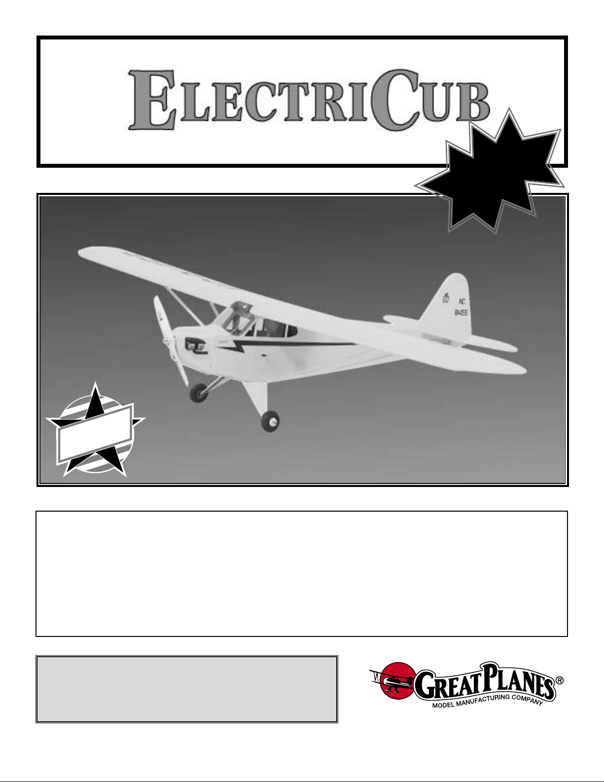
Your ElectriCub is not a toy, but rather a sophisticated,
working model that functions very much like an actual
airplane. Because of its realistic performance, the
ElectriCub, if not assembled and operated correctly,
could possibly cause injury to yourself or spectators and
damage property.
To make your R/C modeling experience totally
enjoyable, we recommend that you get experienced,
knowledgeable help with assembly and during your
first flights.You’ll learn faster and avoid risking your model
before you’re truly ready to solo.Your local hobby shop has
information about flying clubs in your area whose
membership includes qualified instructors.
You can also contact the national Academy of Model
Aeronautics (AMA), which has more than 2,500 chartered
clubs across the country. Through any one of them,
instructor training programs and insured newcomer training
are available. Contact the AMA at the address or toll-free
phone number below.
Academy of Model Aeronautics
5151 East Memorial Drive
Muncie, IN 47302-9252
Tele. (800) 435-9262
Fax (765) 741-0057
or via the Internet at http://www.modelaircraft.org
PRO TECT YOUR MODEL,Y OURSELF
& OTHERS...FOLLOW THESE
IMPORTANT SAFETY PRECAUTIONS
TABLE OF CONTENTS
2
Page 3
1. Build the plane according to the plan and instr uctions. Do
not alter or modify the model, as doing so may result in an
unsafe or unflyable model. In a few cases the plan and
instructions may differ slightly from the photos. In those
instances the plan and written instructions are correct.
2.Take time to build straight, true and strong.
3. Use an R/C radio system that is in first-class condition,
and a correctly sized motor and components (batteries,
wheels, etc.) throughout your building process.
4.You must properly install all components so that the model
operates properly on the ground and in the air.
5.You must check the operation of the model before every
flight to ensure that all equipment is operating and that the
model has remained structurally sound. Be sure to check
nylon clevises or other connectors often and replace them if
they show signs of wear or fatigue.
Remember:Take your time and follow directions to end
up with a well-built model that is straight and true.
Please inspect all parts carefully before starting to
build! If any parts are missing, broken or defective, or if
you have any questions about building or flying this
airplane, please call us at:
(217) 398-8970
or e-mail us at:
productsupport@greatplanes.com.
If you are calling for replacement parts, please
reference the part numbers and the kit identification
number (stamped on the end of the carton) and have
them ready when calling.
Since the original ElectriCub was introduced in 1987, electric
airplanes have grown in popularity and so has the technology.
Over the years modelers have told us what they would like to
see different on the ElectriCub. We've been listening! The
redesigned ElectriCub now comes with ailerons, clear windows
and is designed for mini servos.We've done extensive testing
of motors, gearbox es and props to find the best combination, at
the lowest price, for the new ElectriCub.
While the ElectriCub is easy to fly, it does not have the total
self-recovery and stability of a basic trainer like the Great
Planes series of PT basic trainers. Therefore, if you have
never flo wn an R/C airplane before , we strongly recommend
that you seek out the assistance of an experienced R/C pilot
who will be able to check out your construction and help you
with your first flights.We do know that once you have flown
the ElectriCub you will want to keep it in your vehicle for that
quick flight during your lunch break or to relax with a few
flights after work.
Keep It Light
Because the electric motor and motor battery are relatively
heavier than a glow engine, it is essential that the basic
structure of the airplane be kept as light as possible. In
doing so, you will help insure that the finished airplane will
not be too heavy to fly well.
One way to pre vent excess weight build-up is to use only as
much glue as needed for a good glue joint. Do not apply
extra “fillets” of glue thinking that it will make your plane
stronger! Extra glue could possibly add ounces to the
weight of your plane and detract from the performance.
We will give you tips throughout this book on how to keep
the structure light and we urge you to follow them.
Radio Selection
Because weight is an important factor in the ElectriCub,
the ideal radio system is one that has a miniature
receiver, three mini servos such as Futaba®’s S3101
servos and an electronic speed control with BEC (Battery
Eliminator Circuitry such as the Great Planes Speed 300
GPMM2030). The electronic speed control with BEC
uses the motor battery , not a separate receiv er battery, to
power the receiver and servos. When the motor batter y
voltage reaches a preset voltage, the BEC on the speed
control stops the motor while still supplying power to the
receiver and servos.This setup can reduce the weight of
the plane by as much as 4 oz. However, the ElectriCub
will fly great with four mini servos, a 270 mAh receiver
battery and a micro switch. This setup is a great,
inexpensive way for the first-time electric pilot to try
electric flight. Once you’re hooked on the clean and quiet
advantages of electric flight, you can replace the micro
switch with a high quality electronic speed control.
DECISIONS YOU MUST MAKE
IF YOU'RE NEW TO ELECTRICS
INTRODUCTION
NOTE: We, as the kit manufacturer, provide you with a
top quality kit and great instructions, but ultimately the
quality of your finished model depends on how you build
it; therefore, we cannot in any way guarantee the
performance of your completed model, and no
representations are expressed or implied as to the
performance or safety of your completed model.
SAFETY PRECAUTIONS
3
Page 4
4
Items in parentheses (GPMQ4243) are suggested part
numbers recognized by most distributors and hobby shops
and are listed for your ordering convenience. GPM is the
Great Planes brand, TOP is the Top Flite®brand, HCA is the
Hobbico®brand and COV is the Coverite™brand.
❏ 4 Channel radio with 4 mini ser vos
❏ (2) 2" Ultralight Wheels (GPMQ4201)
❏ (1) 3/4" Tail wheel (GPMQ4240)
❏ (4) 1/8" Wheel collars (GPMQ4304)
❏ (1) 1/16" Wheel collar (GPMQ4300)
❏ (1 Roll) Double-Sided Foam Tape (GPMQ4440)
❏ (1) 1/6 Scale Pilot
❏ (2) Rolls covering film
❏Motor battery pack charger 900 AC/DC Charger (HCAP0125)
or 925 AC/DC P eak Detection Charger (HCAP0198)
❏ 1700mAh 8.4 volt NiCd battery pack (DTXC2071) or
2000mAh 8.4 volt NiCd battery pack (DTXC2076)
Required Accessories
PREPARATIONS
Chargers
A fully charged battery pack will provide an initial “surge”
of power during the first 15 to 30 seconds of the motor
run.Then the power output stays fairly steady for the next
several minutes before dropping off quickly. If you do not
charge your battery completely, it will not deliver that
surge necessary for a good takeoff and climb out.There
are three easy ways to “peak-charge” your battery pack.
1. The easiest way is with a “peak-detecting” battery
charger. This type of charger will automatically charge
your battery until it is fully charged.
2.The second method of charging your motor batteries is
to monitor the voltage of your battery pack with a
voltmeter.Your charger may have sockets into which you
may plug a voltmeter. If not, you may insert the probes
from the voltmeter into the rear of the battery plug,
making contact with the metal contacts. As your battery
charges, the voltage will gradually increase. When the
battery is fully charged, the voltage will start to drop.At
this point your battery is fully charged.
3.The third (and least reliable) method of “peak-charging”
your battery pack is by checking its temperature. As the
battery charges it will remain cool until it is fully charged.
When it reaches the fully charged state, it will rapidly
build up heat.You can feel this heat with your hand. As
soon as the pack starts to noticeably warm up,
disconnect it from the charger. Do not continue
charging if the battery pack is hot! Overcharging will
damage your battery pack and can result in an explosion.
Motor Selection
In testing the ElectriCub, many different motors were
evaluated. Some of them provided adequate thrust to fly
the ElectriCub satisfactorily. Some, however, gave such
marginal performance that the climb-out was very shallow
and flight times were short. Generally, a high perf ormance,
high power motor , like the Great Planes S-600™direct drive
motor, will give the ElectriCub a good climb rate and good
aerobatic capability, but will result in a relatively short run
time of 3 to 4 minutes.
The Great Planes T600r™reverse rotation motor with a
2.5:1 gear drive unit enables the motor to turn a larger,
more efficient propeller at a slower speed. This usually
results in more thrust for a better climb rate and longer
flight times up to 8 minutes. We consider this motor and
gear drive combination (GPMG0760) to be the system of
choice for the ElectriCub.See “Power Systems”on page 5.
Battery Selection
The ElectriCub was designed to fly on a 7-cell 8.4 volt
1700 - 2000 mAh flat battery pack. Even though the
ElectriCub will fly well on an inexpensive motor battery
pack, we recommend a battery pack that uses Sanyo®or
Panasonic®cells. These cells have a low internal
resistance which translates into more power and less heat.
If you are new to electric airplanes (or even cars and
boats) here is a short explanation of NiCd batteries. A
single cell NiCd battery supplies 1.2 volts with no load (not
powering anything). A 7- cell battery pack can supply 8.4
volts (1.2 volts x 7 cells = 8.4 volts).The cell rating in mAh
(milli-amp-hours) is the amount of current the battery can
supply. If a battery is rated at 1700 mAh, the battery can
supply 1.7 amps for 1 hour (or 1 amp for 1.7 hours).This
sounds great – flying for over 1-1/2 hours on a single
battery charge! The bad news is that to produce the power
needed to fly an airplane the size of the ElectriCub, the
motor draws from 15-25 amps. The current consumption
reduces the run time to 4-6 minutes.The good news is that
propellers become more efficient as the speed of the plane
increases.This lowers the current draw, allowing the plane
to fly longer on a single charge, sometimes up to 20%
longer. Also, if an electronic speed control is used, the
motor can be throttled back, increasing the flight time.Most
airplanes only need full throttle during takeoff.
We recommend the use of high quality battery packs.The
higher quality batteries usually have less internal resistance
than the average battery. The higher quality battery will
provide more power to the motor than the average battery.
In NiCd batteries, internal resistance transforms power into
heat. With less internal resistance, there is more power
available to the motor and less heat is generated.We hope
this helps explain NiCd batteries and why a high quality
battery should be used in the ElectriCub.
Page 5
Power Systems
Good: GPMG0755 S-600 Motor System
S-600 motor (GPMG0710)
8 x 4 propeller
Propeller adapter
Wiring harness with fuse and micro switch
Better: GPMG0760 T600GD System with Gear Drive
T600R reverse rotation motor (GPMG0700)
2.5:1 gearbox (GPMG0850)
Propeller adapter (GPMG0855)
10 x 8 propeller for electrics
Wiring harness with fuse and micro switch
Best: GPMG0760 T600GD ESC System with Gear Drive
and electronic speed control
T600r reverse rotation motor (GPMG0700)
2.5:1 gearbox (GPMG0850)
Propeller adapter (GPMG0855)
10 x 8 propeller for electrics
Speed 300 Electronic speed control with BEC and
auto cutoff (GPMM2030)
These are the building supplies that are required. We
recommended Great Planes Pro™CA and Epoxy glue.
❏ 1 oz. Thin Pro™CA (GPMR6002)
❏ 1 oz. Medium Pro CA (GPMR6008)
❏ 6-Minute Pro Epoxy (GPMR6045)
❏ 30-Minute Pro Epoxy (GPMR6047)
❏ Thread locking compound (GPMR6060)
❏ Balsa filler (HCAR3401)
❏ Plan protector (GPMR6167)
❏ Isopropyl rubbing alcohol (70%)
❏ Paper towels
❏ Sanding block and sandpaper (coarse, medium, fine)
❏ Hobby knife (HCAR0105)
❏ #11 blades (HCAR0211)
❏ Single-edge razor blades (HCAR0212)
❏ Razor saw
❏ Razor plane (MASR1510)
❏ Electr ic drill
❏ Dr ill bits - 1/16", 3/32", 7/64", 1/8", 5/32", 11/64", 3/16"
❏ Small Phillips and flat blade screwdrivers
❏ Pliers with wire cutter (HCAR0630)
❏ Sealing iron (TOPR2100)
❏ Heat gun (TOPR2000)
❏ T-Pins (HCAR5150)
❏ Straightedge with scale (HCAR0475)
❏ Cutting mat (HCAR0456)
❏ Builder’s triangle (HCAR0480)
❏ 10-24 Tap and Drill set
❏ Masking tape (TOPR8018)
❏ Panel line pen (TOPQ2510)
❏ CG Machine™(GPMR2400)
❏ Accu Throw™Deflection Meter (GPMR2405)
❏ CA Applicator tips (HCAR3780)
❏ CA Debonder (GPMR6039)
❏ Clevis installation tool (GPMR8030)
❏ Hot Sock™(TOPR2175)
❏ Cur ved-tip canopy scissors (HCAR0667)
❏ Top Flite Precision Magnetic Prop Balancer™(TOPQ5700)
❏ Slot Machine™motorized hinge slotting tool (GPMR4010)
❏ Precision hinge mar king tool (GPMR4005)
❏ Groove tube (GPMR8140)
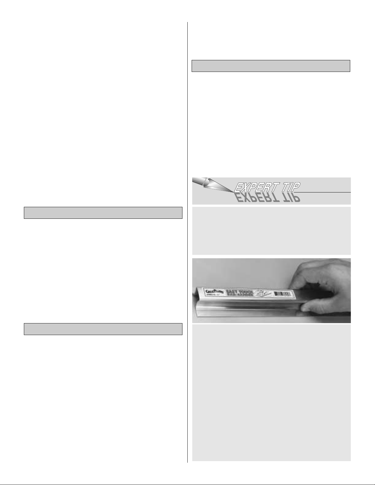
Great Planes Easy-Touch Bar Sanders are made from
lightweight extruded aluminum and can be found at most
hobby shops.They are available in five sizes.
5-1/2” (GPMR6169) for those tight, hard-to-reach spots;
11” (GPMR6170) for most general purpose sanding;
22” (GPMR6172), 33” (GPMR6174) and 44” (GPMR6176)
for long surfaces such as wing leading edges. The Easy-
Touch Adhesive-Backed Sandpaper comes in 2” x 12’
rolls of 80-grit (GPMR6180), 150-grit (GPMR6183) and
220-grit (GPMR6185) and an assortment of 5-1/2” long
strips (GPMR6189) for the short bar sander.The adhesivebacked sandpaper is easy to apply and remove from your
sanding bar when it’s time for replacement.
Custom sanding blocks can be made from balsa or
hardwood blocks and dowels for sanding difficult-toreach spots.
On our workbench, we have three 11” Great Planes
Easy-Touch™Bar Sanders, equipped with #80, #150
and #220-grit sandpaper.This setup is all that is required
for almost any sanding task. We also keep some
#320-grit wet-or-dry sandpaper handy for finish sanding
before covering.
Optional Supplies and Tools
Tools
Building Supplies
5
Page 6
Elev = Elevator Fuse = Fuselage
LE = Leading Edge (front) LG = Landing Gear
Lt = Left Ply = Plywood
Rt = Right Stab = Stabilizer
TE = Trailing Edge (rear) " = Inches
1. Unroll the plan sheets, then reroll the plan inside-out to
make them lie flat.
2. Sort through the sticks and sheets, grouping them by
size. Masking tape can be used to bundle matching sheets
and sticks. Using a felt tip or ballpoint pen, lightly write the
part name or size on each piece or bundle. Refer to the
parts list and plan for sizes and quantities. Use the die-cut
patterns shown on page 7 to identify the die-cut parts and
mark them before removing them from the die sheet. Save
all leftovers.If any of the die-cut parts are difficult to remove,
do not force them! Instead, cut around the parts with a
hobby knife or lightly sand the back of the sheet. After
removing the die-cut parts, use your sanding block to lightly
sand the edges to remove any die-cutting irregularities.
3. As you identify and mark the parts, separate them into
groups, such as fuse (fuselage), wing, fin, stab (stabilizer)
and hardware.
4. Work on a flat surface. Cover the plan with wax paper or
Great Planes Plan Protector to prevent glue from sticking to
the plan.
5.When instructed to test fit parts, this means DO NOT USE
GLUE until you are satisfied that everything fits properly —
THEN glue the par ts together if instr ucted to do so.
6. Whenever the instructions tell you to glue pieces
together, use CA.When a specific type of glue is required,
the instructions will state the type of glue that is highly
recommended. When 30-minute epoxy is specified, it is
highly recommended that you use only 30-minute (or
slower) epoxy because y ou will need either the working time
and/or the additional strength.
7. The easiest way to cut balsa sticks is with a single-edge
razor blade or razor saw. Position the stick over the plan,
mark its size, then cut the part on a piece of leftover wood.
A modeling miter box works well for cutting square corners
and 45-degree gussets.
Zipper-top food storage bags are handy to store the small
parts as you sort, identify and separate them into
sub-assemblies.
IMPORTANT BUILDING NOTES
1/64" = .4mm
1/32" = .8mm
1/16" = 1.6mm
3/32" = 2.4mm
1/8" = 3.2mm
5/32" = 4mm
3/16" = 4.8mm
1/4" = 6.4mm
3/8" = 9.5mm
1/2" = 12.7mm
5/8" = 15.9mm
3/4" = 19mm
1" = 25.4mm
2" = 50.8mm
3" = 76.2mm
6" = 152.4mm
12" = 304.8mm
15" = 381mm
18" = 457.2mm
21" = 533.4mm
24" = 609.6mm
30" = 762mm
36" = 914.4mm
1" = 25.4mm (conversion factor)
Metric Conversions
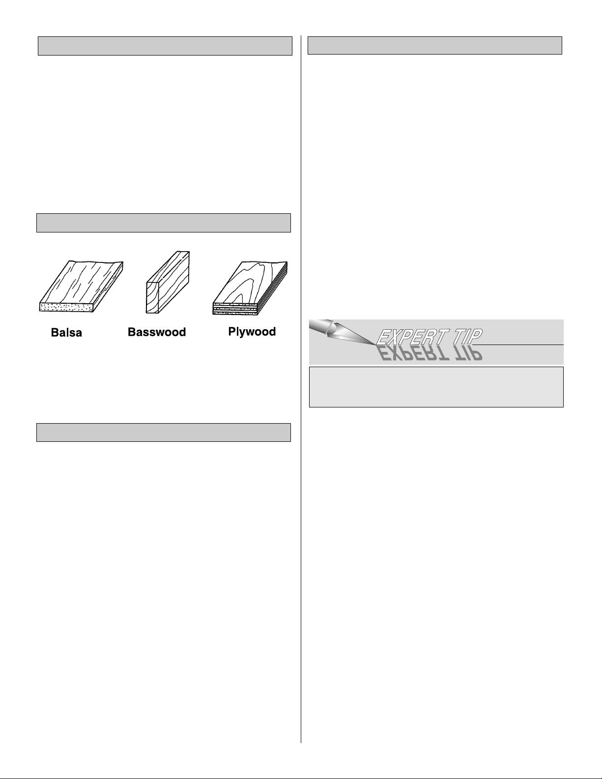
Types of Wood
Common Abbreviations
6
Page 7
7
NOT USED
DIE-CUT PATTERNS
NOT
USED
NOT
USED
Page 8
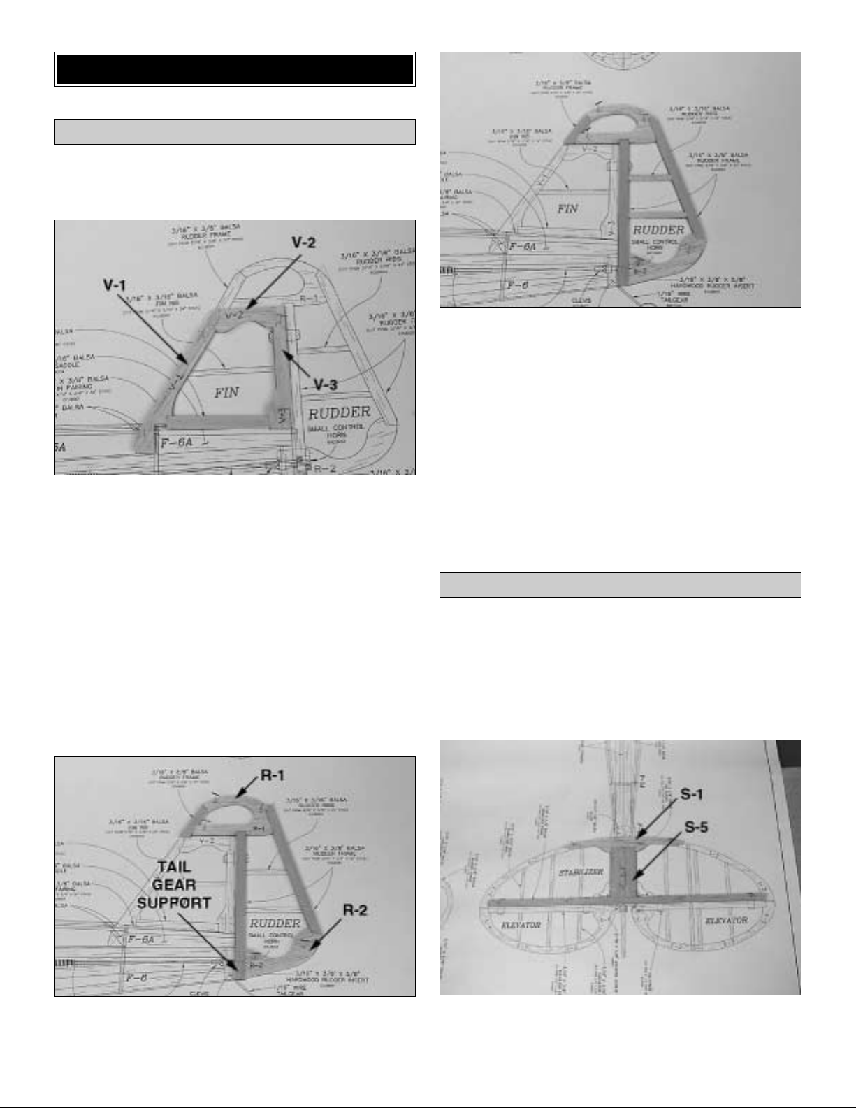
❏ 1. Cover the fin/rudder portion of the plan with wax paper
or Great Planes Plan Protector.
❏ 2. Pin the die-cut 3/16" balsa fin frame V-1, V-2 and V-3 in
position on the fuse plan, sanding the mating edges as required
for a good fit.Use thin CA to glue the fin frame together.
❏ 3. From one of the 3/16" x 3/8" x 30" balsa sticks, cut and
glue a fin base between V-1 and V -3 along the bottom of the fin.
❏ 4. From the 3/16" x 3/16" x 24" balsa stick, cut and glue
the fin rib to the frame.
❏ 5. Remove the fin from your building board.Inspect all the
glue joints and add CA to any joints that don’t look strong.
Fill any gaps with balsa sanding dust and a drop or two of
thin CA.
❏ 6. Build the r udder frame from the die-cut 3/16" balsa R-1
and R-2 frame pieces, a 3/16" x 3/8" x 30" balsa stick and the
small 3/16" x 3/8" x 5/8" hardwood tailgear support.
❏ 7. From the 3/16" x 3/16" x 24" balsa stick, cut and glue
the rudder ribs to the frame.
❏ 8.Remove the rudder from your building board.Inspect all
the glue joints and add CA to any joints that don’t look
strong.Sand the rudder and fin to shape using the fuse plan
as a guide. Sand both sides of the r udder and fin flat and
even.Be careful that you don’t sand any area too thin.
❏ 1. Cover the stabilizer/elevator portion of the plan with
wax paper or Great Planes Plan Protector.
❏ 2. From one of the 3/16" x 3/8" x 30" balsa sticks, cut the
stabilizer trailing edge to match the stabilizer plan. Pin the
stab TE over the plan.
❏ 3. Pin the die-cut 3/16" balsa leading edge S-1 and stab
center S-5 in position. Glue S-1 to S-5 and S-5 to the front
of the stab TE.
Build the Stabilizer & Elevator
Build the Fin & Rudder
BUILD THE T AIL SURF ACES
8
Page 9

❏ 4. Pin the die-cut 3/16" balsa stab frames S-2 and S-3 in
position. Glue S-2 and S-3 to S-1 and the stab TE.
❏ 5. From the 3/16" x 3/16" x 24" balsa stick, cut and glue
the stab ribs to the stab frame.Glue the 3/16" die-cut balsa
stab gussets S-4 to the stab TE and S-5.
❏ 6. Remove the stab from your building board. Inspect,
glue and sand as you did with the fin.
❏❏7.From a 3/16" x 3/8" x 30" balsa stick, cut the elevator
leading edge to length and pin it over the elevator plan.Pin
and glue the die-cut 3/16" balsa elevator frame E-1 through
E-4 to the LE.
❏❏8.From the 3/16" x 3/16" x 24" balsa stick, cut and glue
the elevator ribs to the frame.
❏ 9. Repeat steps 7 and 8 to build the second elevator half.
❏ 10. Remove the elevators from your building board.
Inspect, glue and sand as you did with the fin.
❏ 11. Pin both elevators in position over the plan. Lay the
3/32" elevator joiner wire on top of the elevators in the
position shown on the plan. Use a pencil to lightly mar k the
outline of the joiner wire on the elevators.
❏ 12. Using a straightedge, extend the side lines of the
elevator joiner outline forward to the leading edge.Also, use
a Precision Hinge Marking Tool to draw a centerline on
the leading edge. Using these lines, you can determine
exactly where to drill the holes for the elevator joiner wire.
9
Page 10
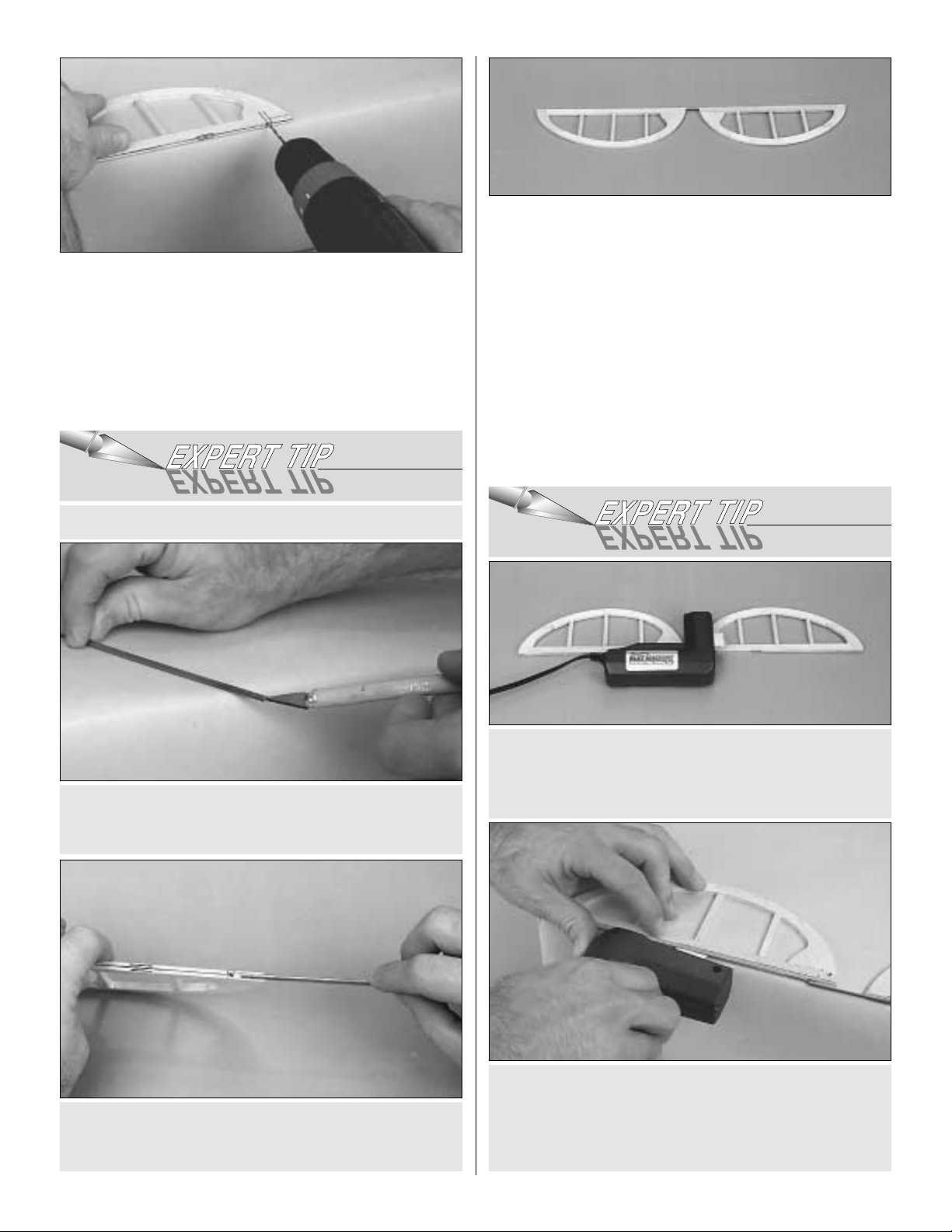
❏ 13. Drill a 3/32" hole into the leading edge of both
elevators. As you drill each hole, keep the drill aligned with
the top and bottom surface of the elevator and reference
lines you made in the previous steps.
❏ 14. Refer to the Expert Tip that follows or use a Great
Planes Groove Tube™to cut a 3/32" groove in the leading
edge of both elevators to recess the joiner wire.
❏ 15.Temporarily join the elevators with the joiner wire.The
joiner wire will be easier to install if you chamfer (bevel) the
ends a little. If necessary, “tweak” the joiner wire so the
elevators are parallel and la y flat on y our building tab le when
the joiner wire is installed. If you found it necessary to
“tweak” the joiner wire, use a felt-tip pen to mark it so you
can install the joiner wire in the same orientation when you
permanently join the elevators.
❏ 16. Lay the elevators and stab over the plan and lightly
mark the hinge locations on the LE of the elevators and the
TE of the stab. Repeat the process to mark the hinge
locations on the LE of the rudder and TE of the fin.
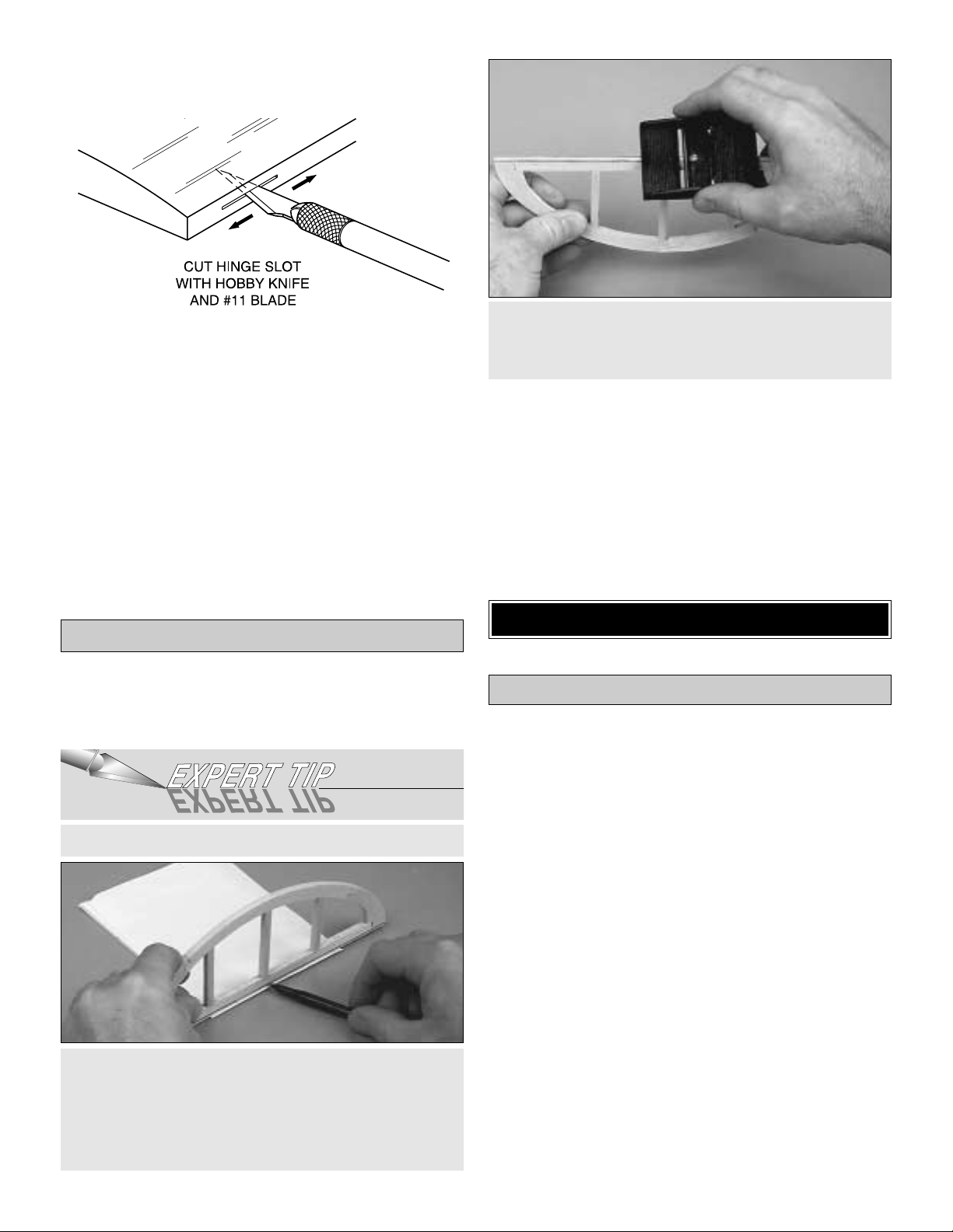
To cut the hinge slot, place the blades onto the wood
where you want the slot. Lightly press the teeth into the
wood.When you are satisfied with the location, press the
button on the handle and the blades will cut easily into the
balsa wood.
We have simplified the task of cutting hinge slots with the
introduction of the Great Planes Slot Machine™. This
simple electric tool cuts a perfect width slot for use with
CA hinges.
B. Use the sharpened tube to carefully gouge the leading
edge of the elevators.You’ll have to make several passes
to make the recess deep enough for the joiner wire.
A. Use a #11 knife blade to sharpen the inside of a piece
of 3/32” brass tube. Roll the tube as you carve the end.
HOW TO CUT A GROOVE FOR A JOINER WIRE
10
Page 11
11
If you choose not to purchase a Slot Machine™you can
make the slots by following these instructions.
❏ 17. Cut the hinge slots in the elevators, stabilizer, fin and
rudder using a Hobby Knife with a #11 blade. Begin by
carefully cutting a very shallow slit at the hinge location to
accurately establish the hinge slot.Make three or four more
cuts, going a little deeper each time. As you cut, slide the
knife from side to side until the slot has reached the proper
depth and width for the hinge.
❏ 18. Cut the 3/8" x 1" hinges for the elevator and rudder
from the supplied 2" x 9" hinge material, then snip off the
corners. Temporarily join the elevators to the stab and the
rudder to the fin with the hinges, adjusting any hinge slots if
necessary so they all align.Do not glue in the hinges until
you are instructed to do so.
❏ 1. Refer to the Expert Tip that follows and shape the
leading edge of the elevators and rudder to a “V” as shown
on the plan.
❏ 2. Use the same procedure to bevel the leading edge of
the rudder.
❏ 3. Temporarily attach the elevators to the stab and the
rudder to the fin. Use your bar sander to round the entire
perimeter of the elevator, stab, rudder and fin (do not round
the bottom edge of the fin where it will be glued to the stab
and fuse).
Start by building the left wing panel right side up over the
left wing panel plan so your progress matches the photos.
❏ 1. Set aside two of the hardest and straightest 1/4" x 1/4"
x 13" balsa sticks for use later to make pushrods.
❏ 2.The shaped and notched balsa wing leading edges are
fastened together by a thin web of balsa.Separate the LE’s
by folding them until the balsa web breaks. Sand away the
excess balsa that remains along the edges, using a sanding
bar with 150-grit sandpaper. Before using the leading edge
you must determine which one to use for the left wing panel.
Here’s how:
A.We have drawn a red line on the top of each piece.
B.The pieces are notched on one end but not on the other.
The notched end goes toward the wing tip.
C. Position one of the leading edge pieces on the left wing
panel plan with the red line up.If the notched end is on the
left side (at the tip) you have the correct piece. (When
building the right wing panel the red line must be up, with
the notched end on the right side, at the tip).
Build the Wing Panels
BUILD THE WING
B.Using the “bevel to”lines and the centerline as a guide,
make the “V” on the leading edge of the elevators with a
razor plane or your bar sander with 150-grit sandpaper.
A. Place the leading edge of one of the elevators on your
work surface and use your pen to mark a “bevel to” line
on both sides, about 3/32” high.
Note: You will probably have to adjust the height of the
elevator with card stoc k so your “be vel to”line is not too high.
HOW TO BEVEL THE LEADING EDGES
Finish the Tail Surfaces
Page 12
12
❏❏3. Cover the left wing panel plan with wax paper or
Great Planes Plan Protector.
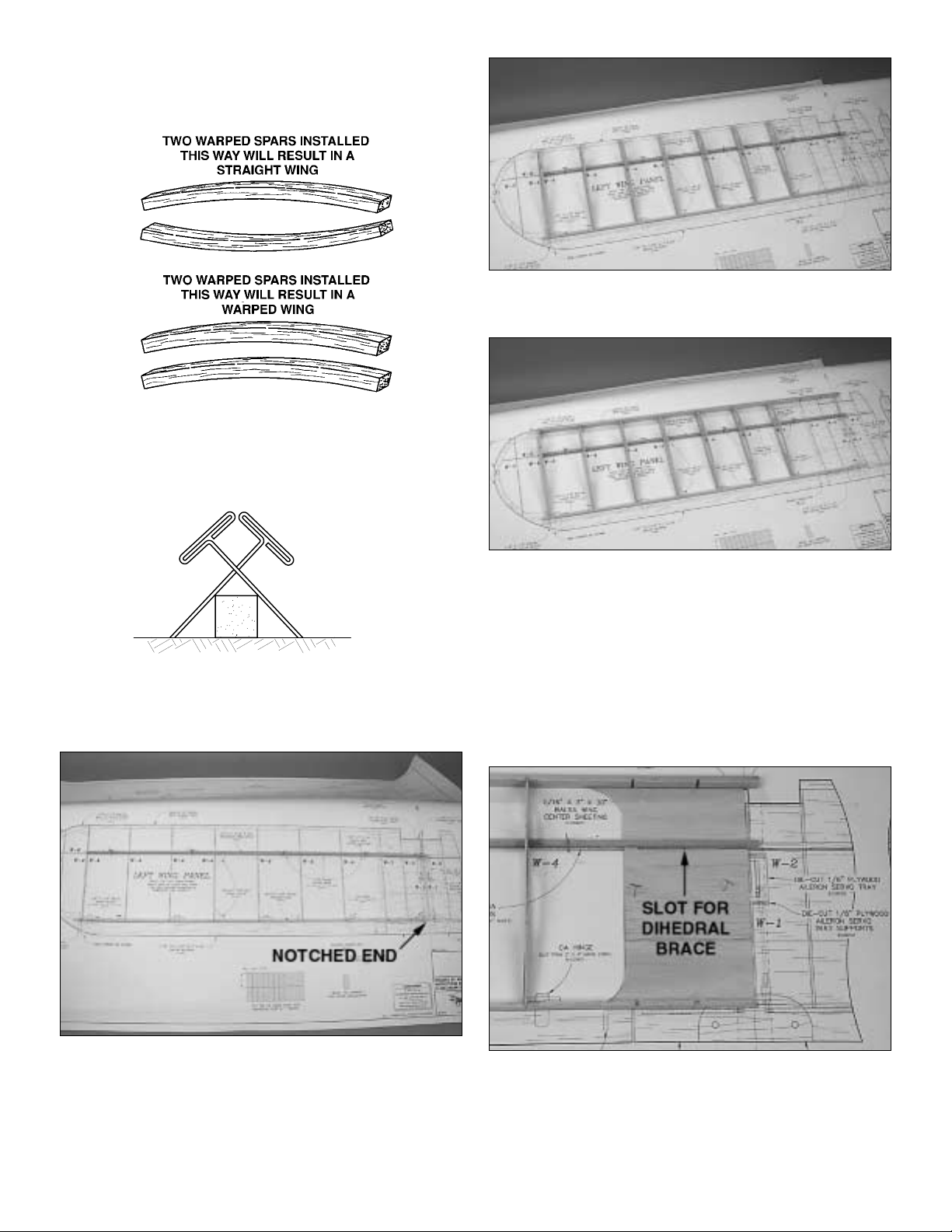
❏❏4. Match the 3/16" x 3/16" x 26-1/4" basswood main
spars so any warps will counteract each other.
❏❏5. Pin one of the main spars in position over the plan,
aligning one end of the main spar with the outside edge of
the tip rib W-4.
❏❏6. Pin one of the die-cut 1/8" balsa trailing edges,
notches facing up, in position over the plan. The TE is
notched at one end and not the other.The notched end goes
toward the wing root (wing center).
❏❏7. Glue two of the die-cut 1/16" balsa W-4 ribs together
to make the tip rib.
❏❏8. Place the W-4 ribs onto the main spar and into the
notches in the trailing edge.
❏❏9. Carefully inser t the W-4 ribs into the notches in the
leading edge. Note: Do not be concerned if the ribs do not
line up exactly with the plan. Sometimes the humidity will
cause the plan to expand or contract.Just make sure to line
everything up with the outside edge of the last rib. The
notches will provide the proper spacing.
❏❏10. With the ribs, LE and TE flat against the building
surface, glue the W-4 ribs to the spar, LE and TE.
❏❏11. From a 1/16" x 3" x 30" balsa sheet, cut the wing
center sheeting to fit between the TE and main spar and
the LE and main spar. Make sure to leave a 1/16" slot, for
the dihedral brace, in the sheeting at the back of the main
spar.Pin the sheeting in position. Then, glue the sheeting to
the main spar, LE and TE.
Page 13
13
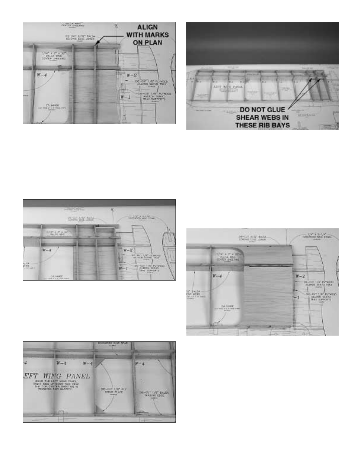
❏❏12. Position the die-cut 3/32" balsa ribs W -2 and W-3 in
position. Important: Rib W-2 does not fit into the notch in the
LE. Rib W-2 fits into the notch in the TE and aligns with the
alignment marks on the wing plan in front of the LE. Glue
only W-3 to the LE, TE, main spar and center sheeting.
❏❏13. Position the top 3/16" basswood spar in the rib
notches with one end flush with the outside edge of the tip
rib and glue to all the ribs except W-2.
❏❏14. Position the die-cut 3/32" balsa rib W-1 in place
between the main spars, with the bottom edge flat against
the center sheeting. Use the die-cut 1/8" ply dihedral
gauge to set the rib at the proper angle (see the drawing on
the wing plan). Position the die-cut 3/32" balsa LE joiner
between ribs W-1 and W-2. When you have W-1, W-2 and
the LE joiner positioned properly, glue them in place.
❏❏15. Glue the two die-cut 1/8" ply wing strut plates in
position.The wing strut plates must be flat on the table, flush
with the bottom of the wing.
❏❏16. From the 1/16" x 3" x 30" balsa sheet, cut and glue
vertical grain shear webs to the spars in the locations
shown on the plan.It is not necessar y for the shear webs to
be glued to the ribs. Make sure they are glued securely to
the wing spars. Do not install shear webs in the rib bays
between ribs W-1 and W-3.
❏❏17.Carefully sand the top of the LE joiner flush with the
top of ribs W-1 and W-2.
❏❏18. From a 1/16" x 3" x 30" balsa sheet, cut pieces to
make the top center section sheeting (don’t forget the 1/16"
notch for the dihedral brace). When satisfied with the fit,
apply medium CA to the top of the ribs and press the
sheeting in place. Note: If the balsa sheeting supplied in
your kit is difficult to bend over the front portion of the ribs
without cracking, wet the top surface of the sheeting with
water.The water will soften the wood, making it much easier
to bend.
❏❏19. From one of the remaining 1/4" x 1/4" x 13" balsa
sticks, cut four 1" long hinge blocks.Glue the hinge blocks
in position, centered on the TE.
Page 14
14
❏❏19. Remove the wing from your building board. Use a
razor saw to trim the LE and top and bottom center sheeting
flush with rib W-2 and the LE joiner. Trim and sand the top
and bottom main spars and center sheeting flush with the
side of rib W-1.Sand the TE flush with the tip rib W-4.
❏❏20. Sand the top and bottom of the LE and TE flush
with the ribs.
❏ 21. Now, go back to step 2 and build the right wing panel.
Remember! Build it over the right wing plan.
❏1. Draw a centerline on the die-cut 1/16" ply dihedral brace.
The top of the dihedral brace has a slight "V" shape.
❏ 2. Using a razor saw, carefully cut a 1/16" slot in ribs
W-1, just behind the main spar.Trial fit the dihedral brace in
the slots.
❏ 3. Sand the bottom of both wing panels near the center, to
remove any excess glue on the spars or sheeting that may
prevent the wing from resting flat on your building board.
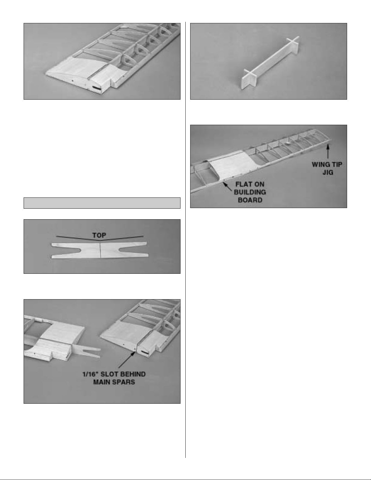
❏ 4.Assemble the die-cut 1/8" ply wing tip jig and wing tip
jig feet.
❏ 5. Trial fit the wing halves together with one wing half flat
on your building board and the wing tip jig under the tip rib
of the other wing panel. Use a sanding bar to sand the
center joint as necessary until the wing halves fit together
without any gap.
❏ 6.When satisfied with the fit, apply 30-minute epoxy to
the dihedral brace, main spars and ribs W-1. Do not apply
epoxy within 1/4" of the wing dowel slot in W-1. You need to
avoid getting epoxy in the slot. Slide the two wing halves
together with the dihedral brace in place.With the two wing
halves aligned, use masking tape to hold the wing halves
together. Wipe off any excess epoxy with a paper towel
dampened with rubbing alcohol. Weight one of the wing
halves down flat on your building board, with the other wing
half supported by the wing jig positioned at the wing tip.
Allow the epoxy to cure before moving the wing.
Note: While waiting for the epoxy to cure, let’s continue with
assembling the wing tips.
Join the Wing Panels
Page 15
❏ 1. Cover the wing tip portions of the wing plan with wax
paper or Great Planes Plan Protector.
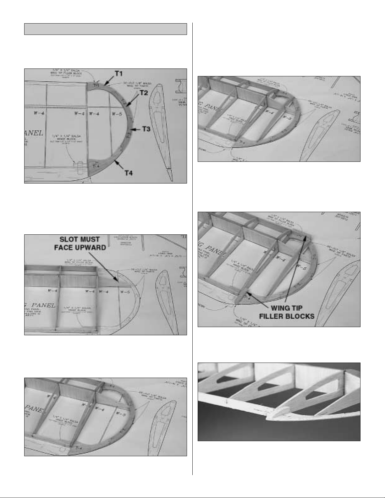
❏❏2. Assemble the wing tip from the die-cut 1/8" balsa
parts T-1, T-2, T-3 and T-4. There are two of each part (one
for each wing tip). Position the wing tip parts over the plan
and glue them together.Fill any gaps with medium CA, then
sand smooth.
❏❏3. With one of the wing panels flat on your building
table, glue the die-cut 1/16" balsa wing tip brace W-6 to the
end of the spars and tip rib W-4. The slot in W-6 must be
facing upward.
❏❏4. Trial fit the wing tip assembly against the end of the
LE and TE. Center the LE of the wing tip on the end of the
wing LE. The TE of the wing tip should rest on the building
table.Sand off the end of W-6 until it just touches the inside
edge of the wing tip.
❏❏5. With the wing tip centered on the LE and resting on
the table at the TE, glue the wing tip to the LE, TE and W-6.
❏❏6. Trial fit the die-cut 1/16" balsa rib W-5 in the notch in
W-6.Sand the rib if necessary for a good fit and glue in place.
❏❏7. Sand the front and rear of W-5 to blend into the
rib contour.
❏❏8. From a 1/4" x 1/4" x 13" balsa stick, cut and glue
wing tip filler blocks on the top and bottom of the wing tip
LE and on the top of the wing tip TE.
❏❏9. Use a sanding bar to blend the filler blocks into the
wing tip.Round the edges of the wing tip.
❏ 10. Go back to step 2 and assemble the other wing tip.
Assemble & Install the Wing Tips
15
Page 16

❏ 1. Cut the tapered and grooved balsa center trailing
edges to the length shown on the plan.Bevel them so they
join as shown on the plan. Test fit the center TE’s on the
wing. Note: The center TE is positioned on the wing with
the 90 degree edge at the bottom of the wing.
❏ 2. Place the center TE’s over the wing plan and mark the
location of the aileron torque rods.To clear the torque rods,
cut notches at the marks on the bottom of the center TE’ s .Test
fit the torque rods in the center TE’s to check for clearance.
❏ 3. Turn the wing upside-down and position the center TE’s
on the wing TE with the torque rods installed. Mark the
location of the notches on the bottom of the wing’s TE. Cut
notches in the wing TE at the marks.Test fit the center TE’s
with the torque rods installed, checking that the notches align
and are large enough to allow the torque rods to move freely.
❏ 4.Use coarse sandpaper to scuff the nylon tube bearing
on the aileron torque rods so that the glue will adhere better.
❏ 5. To prevent gluing the torque rod to the nylon tube
bearing, apply petroleum jelly on the torque rod at the ends
of the nylon tube bearing.
❏ 6.Use 30-minute epoxy to glue the nylon tube bearings in
the center TE’s and the center TE’s to the TE of the wing.
Tape the center TE’s to the wing so that the bottom of the
center TE’s are aligned with the bottom of the wing. Use a
paper towel dampened with rubbing alcohol to wipe off any
excess epoxy before it cures.
Build the Ailerons
16
Page 17

❏❏7. Position the left aileron on the trailing edge of the
wing. Mar k the end of the aileron where it meets the wing
tip.Cut the aileron approximately 1/8" shorter than the mark.
This will allow the aileron to move freely after the MonoK ote
®
covering is applied.
❏❏8. Position the aileron on the wing with a 1/16" gap at
each end.Mark the location of the torque rod on the aileron.
❏❏9.Use a drafting square or triangle to extend the marks
to the LE of the aileron. Mark an accurate centerline on the
entire LE of the aileron and the TE of the wing.
❏❏10. Use the centerline and the marks for the torque rod
as a guide to drill a 7/64" hole in the aileron for the torque
rod. Use the Great Planes Groove Tube or a sharpened
brass tube to cut a groove for the torque rod in the LE of the
aileron.
❏❏11. Test fit the aileron on the wing to make sure the
torque rod fits and there is approximately 1/16" clearance
between both ends of the aileron and wing.
❏❏12. Mark the location of the hinges on the aileron and
wing. Cut the hinge slots in the aileron and wing. Cut four
3/8" wide hinges from the supplied hinge strip. Insert the
hinges in the aileron and fit the aileron to the wing. Do not
glue the hinges at this time.
❏❏13.Sand the tip of the aileron to blend with the wing tip.
❏❏14. Remove the aileron from the wing. Mark the “bevel
to” lines and shape the LE of the aileron to a “V” as shown
on the plan.
❏ 15. Go back to step 7 and fit the right aileron to the wing.
17
Page 18

❏ 1. Use a pen to draw a centerline on the die-cut 1/16"
plywood wing plate. Use a sanding bar to bevel the front
and sides of the wing plate to a sharp edge.
❏ 2. Lightly sand the entire wing smooth. Sand very
carefully in the center section area when removing the
excess glue around the center joint (remember , the sheeting
is only 1/16" thick).
❏ 3. Use 6-minute epoxy to glue the wing plate on the top
of the wing, aligned with the centerline and flush with the
wing center TE.Use masking tape or clamps to hold it tight
against the wing sheeting until the epoxy cures.
❏ 4. Read “Fiberglassing Tips” that follow this step.The
included strip of fiberglass tape is used to reinforce the
center of the wing.The remaining fiberglass tape is used to
reinforce the ends of the wing struts.With the wing upside-
down, use thin CA to glue the fiberglass tape to the center
sheeting starting at the TE and working toward the LE.Then
glue the tape on the top of the wing from the front edge of
the wing plate to the LE. Cut off the excess tape.
❏ 5. Use a sanding bar to carefully “feather” the edges of
the glass tape into the center sheeting. Lightly sand the
surface of the glass tape to remove the roughness, but do
not sand through the weave. A light coat of balsa filler can
also be used to blend the glass tape to the center sheeting.
❏ 6. On the bottom of the wing, draw a line 3/16" back from
the aft edge of the wing spar.
❏ 7. Align the die-cut 1/8" ply aileron tray with the line,
centered on the wing joint.Trace around the aileron tray.
Fiberglassing Tips: If you spray a very light mist of 3M
“77”spray adhesive on the center section (only where the
glass tape is to be applied), you can press the glass tape
in place before applying the thin CA glue.Hold the spray
can at least 16" away from the wing and give it just a
short burst. You may also use a piece of wax paper to
press the glass tape firmly down to the wood immediately
after applying the CA.
Finish the Wing
18
Page 19

❏ 8. Trim the 1/16" balsa sheeting along the outline of the
aileron tray. Cut out the aileron servo opening in ribs W-1.
❏ 9. Glue the die-cut 1/8" ply aileron tray supports on the
end of the aileron tray, perpendicular to the tray.
❏ 10. Insert the aileron tray into the opening in the wing and
glue in position. Cut a small hole in the wing sheeting next
to the aileron tray to route the servo wire out.
❏❏1.With wax paper or Plan Protector positioned over the
fuse plan, pin the die-cut 1/8" balsa forward lower
fuselage (FLF), forwar d center fuselage (FCF) and upper
fuselage (FTF) in position over the plan and glue together.
❏❏2. From the 1/8" x 3/8" x 24" balsa sticks, carefully cut
the three longerons and the tail post to match the plan.
Glue the longerons to the forward fuselage and glue the tail
post to the ends of the longerons.
❏❏3. From the 1/8" x 1/4" x 24" balsa stick, cut and glue
the two side window frames to the forward center and
upper fuselage sides.
Assemble the Fuselage Sides
BUILD THE FUSELAGE
19
Page 20

❏❏4. Use a pen to mark the location on the longerons for
formers F-4, F-5 and F-6.
❏ 5. Remove the fuselage side from the plans. Return to
step 1 and build the second fuselage side.
❏ 6. Place the two fuse sides together and check that they
match up all the way around. If they are not identical, pin
them together and use a sanding bar to make them match.
❏ 7. Lightly sand both sides of the fuselage sides to remove
any excess glue.
❏ 8. Lay the fuse sides next to each other so they mirror
each other.Mark one fuse side left side and one right side.
❏ 9.To provide right thr ust in the firewall, trim 3/32" off the
front of the right fuselage side.
❏ 10. Align and glue the die-cut 1/8" balsa wing saddle
doublers to the inside of both fuse sides with the top and front
of the doubler aligned with the top and front of the fuse side.
❏ 11. Cut the 1/4" x 1/4" x 12" basswood servo tray rail
in half.
❏❏12. Draw a line on the inside of the fuse sides, 1/4"
above the joint between the forward lower fuse and the
forward center fuse.
❏❏13.T emporarily install the die-cut 1/8" plywood former
F-3 in position on the fuse side. Glue the 1/4" x 1/4" servo
tray rail to the fuse side, aligning its bottom edge with the
line drawn in step 12 and former F-3. Do not glue the rail
to F-3.
20
Page 21

21
❏❏14. Position the fuse side over the plan and glue the
die-cut 1/8" plywood battery bench support to the inside of
the right fuse side.When assembling the left side, position the
fuse over the plan and mark the location of the battery bench
support on the outside of the fuselage.Then, transfer the lines
to the inside of the fuselage and install the bench support.
❏❏15. Glue the die-cut 3/16" balsa stab saddle to the top
of the longeron. Make sure the front of the stab saddle
aligns with the mark for the aft edge of former F-6.
❏ 16. Return to step 12 and repeat the steps to assemble
the left fuse side.
❏ 17.Transfer the marks for the formers to the other side of
the longerons on the fuse sides.
❏ 1. From the leftover 1/4" x 1/4" balsa stick (don’t use the two
that have been set aside f or making the pushrods) cut and glue
reinforcements to both sides, at the bottom of the die-cut 1/8"
plywood former F-2A. Make sure the sticks are flush with the
end of the tabs.
❏2. From the leftover 1/8" x 3/8" balsa stick, cut tw o pieces the
full width of the die-cut 1/8" balsa formers F-4 and F-5.Glue
the sticks to the aft side at the top and bottom of the formers.
❏ 3. Install former F-2A on the right fuse side so that the
embossed F-2A faces forw ard.Make sure F-2A is inserted into
the notches completely. Use a building square to hold F-2A
perpendicular to the fuse side while gluing the former in place.
❏ 4. Glue the die-cut 1/8" plywood former F-3 to the right
fuse side. Use a building square to hold F-3 perpendicular
to the fuse side while gluing the former in place.
❏ 5. Join the right fuse side to the left, keying formers F-2
and F-3 to the left fuse side.Lay the fuse on its left side and
glue F-2 and F-3 to the left fuse side, making sure they are
perpendicular to the fuse side. It may help to prop up the aft
end of the right fuse side while performing this step.
Join the Fuselage Sides
Page 22

22
❏ 6. Pull the tail posts together and use a bar sander to
lightly sand the inside edges of the tail posts to an angle.
Align the fuse over the fuselage top view, checking the tail
posts for the proper width.Carefully line up the tail post and
glue them together. Note: A small misalignment here will
throw the aft end out of line, so double-check before gluing.
❏ 7.Test fit the die-cut 1/16" balsa aft deck base between
the forward center fuse sides and the stab saddle.Trim the
aft end of the deck base for a good fit.
❏ 8. Pin the aft deck base to the plan top view (note that the
front of the deck base is flush with the front of F-3).Use the
former locator marks and draw the former location lines on
the aft deck base.
❏ 9.Trial fit former F-4 between the longerons at the former
location lines (the cross braces face aft).Note that the sides
of F-4 and the cross braces will have to be sanded to a
slight taper to make good contact with the longerons.
Remove F-4 and sand as required f or a good fit.Do not glue
F-4 to the longerons.
10. Repeat the above process to properly taper the sides of
F-5 and F-6.
❏ 11. Position F-4 between the former location lines on the
aft deck base. Adjust the position of F-4 so it is centered
between the edges of the aft deck base.Glue F-4 to the aft
deck base, perpendicular to the aft deck base.
❏ 12. Repeat the procedure, gluing F-5 and F-6 to the aft
deck base.Remove the deck base from the plan.
❏ 13. Pin the fuselage over the plan top view. Make sure
former F-3 and the tail post are aligned with the plan.Check
that the sides of the tail posts are perpendicular to the
building board.
Page 23

23
❏ 14.Trial fit the aft deck base and formers on the fuse. At
each former, make sure the deck base seats completely on
the top longeron. Lightly sand the bottom of the formers
as needed.
❏ 15. Glue the aft deck base to the top edge of former F-3.
While applying pressure on the aft deck base at F-4, glue
the top longeron to the aft deck base at F-4. Repeat the
process at F-5 and F-6. Then, proceed to glue the top
longeron to the rest of the aft deck base.
❏ 16.Again, check that the tail post is perpendicular to the
building board (when viewed from the rear).Glue the middle
longerons to the formers.Temporarily apply weight to the aft
deck base so that F-4, F-5 and F-6 are against the building
board. Glue the bottom longerons to the formers.
❏ 17. Turn the fuse upside-down and apply glue along the
joints between the aft deck base and F-4, F-5 and F-6.
❏ 18. Carefully sand the bottom of the fuse flat.
❏ 19. Glue the die-cut 1/8" plywood battery bench back
and the die-cut 3/32" balsa battery bench seat to the
battery bench suppor ts.
❏ 20. Position the fuse upside-down on your building board.
Check that the tail post is perpendicular to the building
board (when viewed from the rear).Sheet the bottom of the
fuse with 1/16" x 3" x 30" balsa sheet, applied cross-grain,
starting at the rear edge of the landing gear plate opening
and proceeding to the tail post. Note: A good way to do this
is to lay the sheet across the fuselage and mark the edge of
the longerons on the bottom of the sheet Remove the sheet
and cut along the mark with a hobby knife, allowing a little
extra that will be sanded off later.
❏ 21.Use a sanding block to sand the bottom sheeting flush
with the sides of the fuse.
❏ 22. Using epoxy, glue the die-cut 1/8" plywood F-1B to the
back of F-1A. This is now called the firewall. Remember, the
side with the embossed “1A”and "1B" is the front of the firewall.
❏ 23. After the epoxy cures, drill 3/32" pilot holes through
the firewall at each of the eight punch marks.
❏ 24. Make a mark 3/32" from one front corner of the die-cut
3/32" balsa front deck base.Trim the end of the front deck
base at an angle to allow for the right thrust in the firewall.
Page 24

24
❏ 25.T rial fit the die-cut 1/8" plywood cabin brace in former
F-2 and the fuse sides. Lay the front deck base in position
and then the firewall assembly, pulling the front of the fuse
together with rubber bands. Sand the front deck base, as
necessary, for a good fit.
❏ 26. Glue the cabin brace to the fuse sides and F-2.
❏ 27. Glue the front deck base to the fuse sides and
cabin brace.
❏ 28. Use 6-minute epoxy to glue the firewall to the fuse
sides and the front deck base. Wipe off any excess epoxy
with a paper towel dampened with rubbing alcohol.Hold the
fuse sides tightly against the firewall until the epoxy sets.
❏ 29. Glue the die-cut 1/8" balsa former F-1C to the front
deck base.
❏ 30. Trial fit the die-cut 1/16" balsa top front sheet,
sanding as necessary. Glue the front sheet to the firewall,
F-1C and the front deck base.If the front sheet is hard balsa
and difficult to bend, wet the top surface of the sheet with
warm water before bending around the formers.
❏ 31. From the leftover 1/8" x 1/4" balsa stick, cut side
window frames to fit flush with the front of the cabin brace.
❏ 32.Fit the 3/16" plywood landing gear plate between the
fuse sides. Use 6-minute epoxy to glue the landing gear
plate to the fuse sides and the bottom of former F-2.
To reduce weight, before installing the top front sheet cut
lightening holes in the front deck as shown on the plan.
Page 25

❏ 33. From the 1/4" x 1/4" x 5-7/8" balsa triangle stick, cut
and glue three pieces to fit in the lower front corner of the
fuse. Sand the tr iangles flush with the bottom of the fuse.
❏ 34. Glue the three die-cut 1/32" plywood cowl screw
backplates to the inside of the fuse sides and top
front sheeting. See fuselage plan side view.
❏ 35.From leftover 1/16" balsa (use a piece from a die-cut
sheet), cut a 1/2" x 1-1/2" piece. Glue the piece to the aft
end (wide end) of the die-cut 1/8" plywood battery hatch.
Sand the aft end of the battery hatch to match the angle on
the front of the landing gear plate.
❏ 36. Glue the die-cut 1/32" x 5/8" x 1-1/2" plywood
hatch plate to the balsa strip on the aft end of the battery
hatch.The hatch plate should extend about 1/8" past the
aft edge.
❏ 37. Glue the die-cut 1/32" x 1/2" x 1-1/4" plywood hatch
stop to the aft end of the die-cut 1/8" plywood chin plate so
that it extends 1/8" behind the aft edge.
❏ 38. Position the battery hatch and chin plate on the fuse,
using the battery hatch as a spacer to determine the
location for the chin plate.While holding the chin plate firmly
in position, remove the battery hatch and apply thin CA
around the chin plate to secure it in place.
❏ 39. From leftover 1/32" plywood, make the hatch locking
tab as shown in the sketch.
25
DRILL 3/32"
HOLE
(ACTUAL SIZE)
1/32" PLYWOOD
Page 26

❏ 40. Center the hatch locking tab on the aft edge of the
chin plate. Mark the location of the screw hole on the chin
plate and drill a 1/16" pilot hole.
❏ 41.Attach the hatch locking tab to the chin plate with a #2
washer and #2 x 3/8" sheet metal screw.
Note: The hatch locking tab is designed to keep the battery
hatch closed during flight, yet it allows quick access to the
front compartment for easy insertion and removal of the
motor battery. You must adjust the tab screw for
sufficient friction so it will not allow the battery hatch to
open during flight. Periodically check and re-tighten the
screw if necessary.
❏ 42. Glue the die-cut 1/8" balsa former F-3A to the rear
edges of the upper fuse sides and the aft deck base.
❏ 43. Glue the die-cut 1/8" balsa rear wing saddle into the
slots in the wing saddle doublers, flush with the top of the
wing saddle.
❏ 44.Use epoxy to glue the three die-cut 1/8" plywood wing
bolt plates together.Use clamps to hold the plates together
until the epoxy cures.
❏ 45.Lightly sand the edges of the wing bolt plate to remove
any excess epo xy.Test fit the wing bolt plate into the slots in
the fuse sides, sanding as necessary to provide a good fit.
When satisfied with the fit, use epoxy to glue the wing bolt
plate to the fuse.
To reduce the weight of the wood structure, you can
enlarge the lightening holes by 1/16" in the lower fuselage
sides. A drum sander or a piece of sandpaper wrapped
around a dowel makes quick work of it.
26
Page 27

❏ 46. Using the marks for formers F-4 and F-5 on the side of
the longerons, draw lines across the top of the aft deck base.
❏ 47.Glue the die-cut 3/32" balsa formers F-4A and F-5A
between the lines, perpendicular to the aft deck base.
❏ 48. Glue the die-cut 3/32" balsa former F-6A to the front
of the stab saddle and the aft deck base.
❏ 49. From leftover 1/8" balsa (soft balsa preferred) cut two
pushrod exit plates to the approximate shape as shown.
❏ 50.Fit and glue the pushrod exit plates in front of former
F-6, between the upper and middle longerons.
❏ 1. Fill any small gaps in the fuselage with balsa filler.
❏ 2. Use a sanding bar to sand the fuse sides and bottom
smooth. Sand the top front sheeting and chin plate flush
with the firewall.
❏ 3. Sand the lower corners of the chin plate, battery hatch,
landing gear plate and bottom sheeting to a slightly rounded
shape as shown on the plan.
❏ 4. Lightly sand the front top sheeting to blend into the
fuse sides.
❏ 5. Sand the wing saddle area slightly to remove any
excess glue.
Sand the Fuselage
To reduce the weight of the plane, you may cut large
lightening holes in the aft deck base (between the
formers). Leave approximately 3/8" of material along the
sides and 3/4" near the formers.
27
Page 28

❏ 1. Position the wing in the wing saddle and visually align
it with the fuselage.The center joint of the wing should align
with the hole in former F-2.
❏ 2.Transfer the hole location onto the wing LE joiner and
carefully cut out the hole to fit the 1/4" wing dowel.
❏ 3. Round both ends of the 1/4" x 1-1/2" wing dowel. Use
epoxy to glue the wing dowel in the LE joiner and the slot in ribs
W-1.Make sure the dowel is perpendicular to the LE joiner and
protrudes 1/2" out of the forward wing joiner.
❏ 4. After the epoxy cures, reinstall the wing on the fuse.
Use epoxy to glue the die-cut 1/8" plywood wing dowel
doubler to the front of former F-2. Before the epoxy cures,
carefully remove the wing from the fuse.
❏ 5. Place the wing in the wing saddle and visually align it
with the fuselage. Use a tape measure to measure the
distance from the corner of the aileron bay to the center of
the tail post. Then, measure the distance from the other
aileron bay and check if the distances are the same.Adjust
the wing until both distances are equal. When the wing is
perfectly aligned, make reference marks on the wing
trailing edge and former F-3A to help keep the parts aligned
during the next step.
❏ 6. Tape the wing in position so that it cannot move. Use a
5/32" (or #25) drill bit to drill a hole through the wing and wing
bolt plate.Two small 90-degree triangles will help you to align
the drill perpendicular to the top surface of the wing.Important:
Do not allow the wing to shift during this procedure.
❏ 7. Remove the wing and use a 13/64" drill bit to enlarge
the holes in the wing only.
❏ 8.Use a #10-24 tap to cut threads into the wing bolt plate.
After cutting the threads, put a couple of drops of thin CA on
28
Page 29

the threads in the wing bolt plate. After the CA has fully
cured, thread the tap back through the holes to clean up the
threads.Bolt the wing to the fuse with two nylon 10-24 wing
bolts, checking the fit.
❏ 9. Trim the clear windshield along the embossed “cut
lines.” Then, tape it in position on the front of the cabin.
❏ 10. With the wing installed, note the gap between the LE
of the wing and the windshield. Install shims made from
1/16" balsa sheet to reduce the gap to 1/32" on each side.
❏ 1. To aid in alignment, draw an accurate centerline on
the top of the stabilizer. This centerline should be in the
middle of S-5 and perpendicular to the TE.
❏ 2.Mount the wing on the fuse. Center the stabilizer on the
stab saddle, aligning the centerline of the stab with the
centerline of the fuse. From a few feet behind the fuselage,
view the stabilizer , checking that the stabiliz er is parallel with
the wing. If not, remove the stabilizer and sand the saddle
slightly.The front of the stab may need to be sanded slightly
so that the stab TE is flush with the aft end of the fuse.When
satisfied with the fit, use 30-minute epoxy to glue the stab to
the fuse. Double-check the stab alignment while the
epoxy is curing.
❏ 3. Set the fin in position on the stab. The fin TE must line
up with the aft edge of the fuselage tail post. If the fin is too
far forward, sand V-1 slightly to allow the fin to slide back
until the TE lines up properly. Also, the bottom of V-1 may
need to be sanded to allow the fin to seat on the stab.
❏ 4. Measure 1/8" on each side of the stab centerline and
draw two lines parallel with the stab centerline.
Mount the Stabilizer & Fin
29
Page 30

❏ 5. Set the fin in place, using the lines as a guide. Sight
down the fin, checking that it is in line with the centerline of
the fuselage. It is very important that the fin be aligned with
the centerline of the fuse.If it is not, the plane will be difficult
to trim. Use a square to check that the fin is perpendicular
to the stab. Use 30-minute epoxy to glue the fin to the stab
and aft deck base.
❏ 6. You previously cut the hinge slots in the rudder and fin
TE. Mar k the location of the bottom rudder hinge on the
fuselage tail post.
❏ 7 Cut the hinge slot in the fuse tail post and trial fit the
bottom rudder hinge in place.
❏ 1. Position one of the 1/8" diameter dowels in the center
notches of F-3A, F-4A, F-5A and F-6A. Sand the aft end of
the dowel at an angle to match the angle of the fin LE.Glue
the dowel in place. Then, cut off the forward end of the
dowel flush with the front of F-3A.
❏ 2. In a similar manner, cut and glue the other two 1/8"
dowels in position.
Note: If you examine the fuse plan you will notice that there
are 1/8" balsa filler pieces in the area in front of the fin.The
purpose of these pieces is to make the fuse easier to cover
and enhance the scale appearance.
❏ 3. Fit and glue the die-cut 1/8" balsa filler pieces
between the dowel stringers and fin and the dowel stringers
and aft deck base.
❏ 4. From a leftover piece of 3/16" balsa, cut a piece to fit
between the fin LE and the top dowel stringer. Glue it in
place and sand the top edge to a rounded shape to match
the fin LE.
Install the Dowel Stringers
30
Page 31

31
❏ 5. From a leftover 1/8" x 3/8" stick, cut a piece
approximately 4-1/4" long to fit on the side of the fin, from
former F-6A to the TE of the fin. Cut the piece in half
diagonally to make two fairings.
❏ 6. Sand the top surface of the fairings to a rounded shape.
❏ 7.Test fit the fairings in place.The forward edge should be
flush with the top of former F-6A. When satisfied with the fit,
glue the fairings in place on both sides of the fin/stab joint.
❏ 8. Apply balsa filler to any gaps around F-6A to blend the
fairings into the fin and stab.
❏ 9. From leftover 1/8" balsa, make gussets to fit at the joint
between the outside dowel stringers and former F-3A.
❏ 1. Turn the fuse upside-down and position the 1/8" wire
main landing gear on the 3/16" ply landing gear plate as
shown on the plan.T ac k glue it in place with a drop of thin CA.
❏ 2. Position the three nylon landing gear straps over the
main landing gear as shown on the plan. Mark the screw
hole locations on the landing gear plate.
❏ 3. Drill a 1/16" diameter pilot hole at each location
you marked.
❏ 4.Temporarily secure the main landing gear to the landing
gear plate with the landing gear straps and six #2 x 3/8" screws.
To reduce the weight of the plane, we recommend drilling
several 1/4" diameter holes through the landing gear
plate.Be careful to not drill through former F-2 or close to
the landing gear straps.
Mount the Landing Gear
Page 32

32
❏ 5. On the LE of the rudder, drill a 1/16" hole, centered
in the LE of the tailgear support, 3/8" from the bottom of
the rudder.
❏ 6. Use the threaded end of one of the threaded pushrod
wires to file a small slot in the LE of the tailgear support for
the 1/16" tailgear wire.Test fit the tailgear wire in the rudder.
Do not glue it in place until after the rudder is covered.
❏ Important: If you will be installing a motor with a diameter
of 1-29/64" (such as a Great Planes S-600 motor with a flux
ring) sand the raised area of the die-cut 1/8" plywood motor
mount sides flat.
❏ 1. Drill a 1/8" hole at each of the punch marks on the die-cut
1/8" plywood motor mount back and motor mount front.
❏ 2.Glue the two lower motor mount sides perpendicular to
the motor mount back.
❏ 3. Glue the two upper motor mount sides perpendicular
to the motor mount back.
❏ 4. Glue the motor mount front, flush with the motor
mount sides.
❏ 5. Use medium CA to reinforce all the glue joints on the
motor mount.
❏ 6.If you will be using an S-600 direct drive motor, test fit
the motor in the motor mount and secure it with two 3mm x
6mm machine screws and a rubber band at the rear.
Build the Motor Mount
Page 33

33
❏ 7. If you will be using a Great Planes T-600R Reverse
Rotation motor with a Great Planes 2.5:1 gear drive, test fit
the motor and gear drive in the motor mount and secure it
with three rubber bands, two behind the gear drive and one
at the back of the motor mount.
❏ 8. Use four #4 x 1/2" sheet metal screws to temporarily
attach the motor mount to the firewall.The direct drive setup
is mounted in the top holes.The gear drive setup is mounted
in the second set of holes, from the top.
❏ 1.Carefully trim the cowl along the mold seam at the back
of the cowl. Use a hobby knife or Curved-Tip Canopy
Scissors to cut out the propeller shaft hole and the vent
holes in the front of the cowl.Also cut out the cooling air exit
hole on the bottom of the cowl.
❏ 2.There are three small indentations near the rear edge
of the cowl, one on top and one on each side, toward the
bottom.These are the mounting screw hole locations. Drill a
3/32" diameter hole at each location.
❏ 3. With your electric motor mounted, slide the cowl into
position. Make sure the propeller shaft is centered in the
hole and there is approximately 1/16" clearance between
the front of the prop adapter and the cowl. Mark the cowl
screw hole locations on the fuselage.
❏ 4. Drill 1/16" diameter pilot holes in the fuse for the cowl
screws. Temporarily mount the cowl to the fuse with #2 x
3/8" sheet metal screws.Do not over-tighten the screws.
Mount the Cowl
Page 34

34
❏ 5. Cut out the dummy engines and exhaust pipes.Test fit
them on the cowl.The cylinder heads should line up with the
prop shaft of the real motor.Trim and sand as required for a
good fit.We waited until after the cowl and dummy engines
were painted before gluing them together.
❏ 6. Since you are cutting out plastic par ts, cut out the two
hub caps also. Test fit them on your 2" main wheels (not
included). When satisfied with their fit, set them aside until
after they are painted.
Note: The wing struts are optional (for scale like appearance)
and are not required for flying. They do, however, add
strength to the wing and do not seem to noticeably reduce
the performance.
❏ 1. Sand the 3/32" x 1/4" x 16-1/4" hardwood sticks to an
airfoil shape as shown on the wing plan.
❏ 2.Working over the wing strut drawing on the wing plan,
make two sets of struts as shown. Note that where the
struts join you must cut one of the struts off at an angle
before gluing them together.
❏ 3. Reinforce the ends of the struts by wrapping small
pieces of fiberglass around the struts and applying CA
glue. Sand the str uts smooth.
❏ 4. Drill 1/16" diameter pilot holes in the ends of the struts
where shown for the mounting screws.
Note: The struts will be mounted to the wing and fuse after
the plane is covered.
Note: The Electr iCub was designed to use mini servos on
all control surfaces.If you are installing an electronic speed
control, the throttle servo, receiver battery (if the speed
control has BEC and auto cutoff) and the toggle switch can
be omitted.
❏ 1. Prepare the servos by installing the rubber grommets
and brass eyelets into each servo.
❏ 2. Place the ser vos into the die-cut 1/8" plywood servo
tray and position them so they do not touch the sides of the
openings. Mark the servo mounting holes on the servo tray.
Remove the servos and drill 1/16" pilot holes at the marks.
Mount the servos to the servo tray using the mounting
screws provided with the servos.
❏ Note: If an electronic speed control is used, assemble the
speed control tray and mount it in the top opening in former
F-2A. The speed control can be held in place with a piece
of V elcro®applied to the top of the tray and the bottom of the
speed control.
❏3.Mount the receiver switch on the side of the fuse.We found
a good place for the switch is just behind f ormer F-2A along the
joint between the bottom fuse side and middle fuse side.
Mount the Servos
RADIO INSTALLATION
Construct the Wing Struts
Page 35

❏ 4. Wrap the receiver and receiver battery (if used) in 1/4"
foam rubber.
❏ 5. Temporarily position the receiver and receiver battery
on the fuse bottom, in front of former F-3.Later, the receiver
battery may be moved forward or aft to balance the plane.
Plug the receiver battery into the receiver switch.
❏ 6. If you are installing one of the Great Planes motor
packages with the switch harness, mount the toggle switch
on the side of the fuselage.
❏ 7. Place the servo tray in the fuse. Do not attach it to the
servo tray rails. It will be attached later, allowing it to be
moved forward or aft to balance the plane. Plug the servos
and receiver switch into the receiver.
❏ 8. Cut and sand one of the servo control wheels to a
“cam” shape, similar to that shown on the plan. Clean the
micro switch and the top of the throttle servo case with
rubbing alcohol. Mount the micro switch to the top of the
throttle servo case with double-sided foam tape in such a
way that when you advance the transmitter throttle stick to
full throttle (pushed towards the top of the transmitter), the
servo wheel will activate the micro switch. When satisfied
with the operation of the switch, secure the switch to the
servo by wrapping with a narrow strip of strapping tape.
❏ 9. Charge the motor battery following the instructions
included with your charger.
❏ 10. Make sure the propeller is removed before testing
your motor system. Plug the motor battery into the switch
harness and activate the toggle switch. The motor should
begin running when the transmitter throttle stick is pushed
forward to full throttle and stop when the stick is pulled bac k.
With the toggle switch in the off position, you should not be
able to start the motor with the throttle stick. In order for
this safety feature to be effective, you should always
keep the toggle switch in the “off”position until you are
ready to fly.
NOTE: If you are using an electronic speed control,
install it at this time following the instructions provided
with the speed control. Test run the motor and speed
control to make sure it operates properly.
❏ 11. Unplug and remove the motor battery from the plane.
❏ 1. Separate the nylon control horns from the nut plates.
❏ 2.Lay the rudder on the fuse plan side view and determine
the location for the nylon control horn. While holding one of
the control horns in position on the left side of the rudder,
mark the mounting hole location on the rudder.
❏3.Drill a 3/32" diameter hole through the rudder at each mark.
❏ 4. Mount the control horn on the r udder with two 2-56 x
3/8" machine screws and the nylon nut plate.
❏ 5. Repeat the process to mount the control hor n on the
bottom right side of the elevator.
❏ 6. Reinstall the elevator on the stabilizer, but do not glue
in the hinges.
❏ 7. Position the rudder on the fin and mark on the rudder
the location of the elevator joiner wire .Cut a notch in the LE
of the rudder to allow the elevator to move freely when the
rudder is installed on the fin.
❏❏1. Clean two of the 2-56 x 12" metal pushrods with
rubbing alcohol and a paper towel to remove any oily
protective coating.
❏❏2. Locate the two 1/4" x 1/4" x 13" balsa pushrod sticks
set aside when building the wing.Mark one of them “rudder,”
the other “elevator.”
❏❏3. Lay the elevator pushrod on the fuse top view. Note
that the front pushrod wire attaches to the top of the balsa
pushrod and the rear wire attaches to the right side.To
avoid confusion later, draw lines 1-3/8" long on the pushrod
where the wires will be attached.
Make the Pushrods
Install the Nylon Control Horns
35
Page 36

❏❏4. Use the threaded end of one of the wire pushrods to
“file” grooves in both ends of the pushrod where you drew the
lines.The grooves need not be deeper than ½ the thickness
of the wire.
❏❏5. Drill 5/64" diameter holes through the pushrods
1-3/8" in from each end, at the end of the grooves y ou made
in step 4.
❏❏6.Bend one of the threaded wire pushrods to match the
drawing of the elevator rear pushrod wire (top view). At the
front end of this wire drawing, note that the wire makes a
90-degree bend and goes into the balsa pushrod.Make this
bend and cut the excess wire off. Do not dispose of the
excess wire.
❏❏7. Use sandpaper to roughen the non-threaded end of
the wire.
❏❏8. Insert the wire into the hole and groove in the balsa
pushrod. Apply a couple drops of thin CA to hold the wire
in place.
❏❏9. Sand the end of the pushrod to a rounded shape.
❏❏10. Wrap kite string or strong thread (not included)
around the wire and balsa pushrod.Then apply medium CA
on the string.
❏❏11. Make a 90-degree bend on one end of the leftover
piece of wire pushrod cut off in step 6. Use sandpaper to
roughen the end of the pushrod with the bend.
❏❏12.Insert this rod into the hole and groov e in the front end
of the elevator pushrod, wrap with thread and apply thick CA.
❏ 13. Repeat steps 1 to 12 to make the rudder pushrod.
Notice that the groove in the front of this pushrod is on the
top and the groove in the rear is on the left side.
❏ 14. Determine the location of the pushrod exit slots and
mark them with a pencil.The elevator pushrod exit slot should
be cut near the top of the right pushrod exit plate.The rudder
pushrod exit slot should be cut near the bottom of the left
pushrod exit plate.Drill 1/8" holes at the front and rear of the
slot location.Then use a hobby knife to cut out the slot.
36
Page 37

❏ 15. Temporarily install the elevator and rudder pushrods
by inserting them through the hatch opening and out the
pushrod exits.Install the clevises.
❏ 16. Operate the pushrods manually (with your fingers)
and inspect the installation carefully, checking that the
pushrods do not bind against each other or the formers.
SPECIAL NOTE: Do not confuse this procedure with
“checking the C.G.” or “balancing the airplane fore and
aft.”That very important step will be covered later in the
manual.
Now that you have the basic airframe nearly completed, this
is a good time to balance the airplane laterally (side-to-side).
Here is how to do it.
❏ 1. Temporarily attach the wing and motor to the fuselage.
❏ 2.With the wing level, lift the model by the motor shaft and
the bottom of the rudder (this may require two people). Do
this several times.
❏ 3. If one wing tip consistently drops when you lift the
plane, it means that side is heavy. Balance the airplane by
gluing weight to the inside of the other wing tip.
Note: An airplane that has been laterally balanced will track
better in loops and other maneuvers.
Fill any scuffs and dings with balsa filler or by “expansion.”
See Expert Tip below. After the filler has dried, use
progressively finer grades of sandpaper to e v en and smooth
all the edges, seams and surfaces. Remove all the balsa
dust from the model with compressed air, a tack cloth or a
vacuum with a brush.
The ElectriCub does not require much painting to obtain the
scheme shown on the box, as most of the finish is done with
Top Flite®MonoKote®covering.The only painting required is
the cowl, windshield frame, dummy engine and hubcaps.
The technique we will describe here is how the model
pictured on the box was finished. Remove the motor,
landing gear, windshield and control horns.
Cover the model with Top Flite MonoKote film, using the
sequence that follows.The use of a Top Flite MonoKote Hot
Sock™on your covering iron will prevent scratching the
MonoKote film.
Before you cover the fuselage, first apply 1/4" wide strips of
MonoKote film in the corners where the stab and fin meet the
fuselage. Proceed to cover the stab with pre-cut pieces that
meet in the corners and overlap the 1/4" strips.Do not,under
any circumstances, attempt to cut the covering on the
stab after it has been applied except around the leading
and trailing edges and the tips. Modelers who do this may
cut through the covering and into the stab.This will weaken
the structure to a point where it may fail during flight.
Some modelers prefer to cover the top and bottom of the
ailerons with one strip of MonoKote film. This is done by
covering the bottom first, then wrapping the MonoKote film
up over the leading edge.
We used Top Flite MonoKote Cub Yellow (TOPQ0220) to
cover our ElectriCub.
Covering the Model
Many surface blemishes on a framed model are caused
by bumps and balsa chips on the work surface.This type
of “ding” is best repaired by applying a drop or two of tap
water to the blemish, then running a hot sealing iron over
the spot to expand the wood fibers.After the surface has
dried, sand the expanded area smooth.
Final Sanding
FINISHING
BALANCE THE PLANE LATERALLY
37
Page 38

Suggested Covering Sequence
Fuselage and Tail:
1. 1/4" strips at fin and stab as described
2. Fin TE, followed by stab TE
3. Fuselage bottom
4. Fuselage right side
5. Fuselage left side
6. Fuselage top
7. Stab bottom, followed by top
8. Fin left side, followed by right side
9. Elevator LE
10. Elevator bottoms, followed by the top
11. Rudder LE, right side followed by the left side
12. Battery hatch cover (trim the covering from over
the openings)
13. Landing gear fairing
Wing:
1.Trailing edges of wing
2. Bottom right, followed by the left wing panel
3.Top right, followed by the left wing panel
4. Aileron LE, followed by the bottom and top
5.Wing struts
Add Washout (Wing Twist)
An important characteristic of most air planes is their ability
to stall gently. One way to achieve this is with washout built
into the wing.Washout is when the wing is twisted at the tips
so that the TE of the wing is higher than the LE. This will
cause the wing to first stall next to the fuselage, not at the
tip. Because the ElectriCub is designed to be very light,
washout would be difficult to build into the wing. The
following procedure will explain how to put washout into the
wing by shrinking the plastic covering. You will find that
some coverings will stay tighter than others. Fabrics seem
to relax slightly over time and ma y require re-shrinking more
than once.
To put washout in the ElectriCub wing, have someone hold
the center of the wing firmly down to the flat building
surface.Now grasp the tip of the wing and twist it so that the
trailing edge raises off the surface. While holding in this
twist, use a heat gun to “re-shrink” the covering. Heat both
the top and the bottom. When you let go of the tip, you will
see that the wing will retain some of the twist.
You must continue twisting and re-shrinking until the TE is
1/4" off the surface at both tips. As an aid in getting this
height correct, you may make a small wood block 1/4" high
by gluing together pieces of leftover wood. Keep this block
handy while twisting and heating, to check your progress.
Depending on what type of covering you have used, you
may find that, in time, some of the washout may disappear.
Check it after an hour and repeat the above process if
necessary. Also, recheck it periodically before you go flying.
Top Flite LustreKote®is a high quality paint that perfectly
matches Top Flite MonoKote. The paint is well suited to
putting a high quality finish on ABS (cowl and dummy
engine), but does have a tendency to curl materials such as
styrene and butyrate (windshield and side windows).
The following procedure allows you to airbrush LustreKote
with good results. The recommended procedure requires
that the paint be sprayed into a jar or plastic mixing cup.
This is best done by spraying the paint through a small
brass tube or straw into the jar. For best results spray no
more than ½ oz. of paint into the jar at a time. As the
propellant “boils off” it will cause the paint to foam slightly.
Leave the paint in the open container, stirring every 15
minutes until no more foam appears on the surface of the
paint and the paint has warmed to room temperature. This
allows the propellant and some of the thinner to evaporate
out of the paint.Depending on the amount of paint in the jar,
this process may take about 1 hour.
After allowing the propellant to boil off, use an airbrush to
spray paint the windshield. If the paint is too thick to spray
properly, it can be thinned with a small amount of lacquer
thinner.Do not thin with more than 40% thinner. In general,
about 10% thinner will adequately thin the paint for
airbrushing.The paint can also be brushed on, but brushing
will not produce the high quality finish of spraying.
Do not paint the clear windshield with LustreKote directly
from the can. It can cause the plastic to curl. We
recommend Formula-U for painting the clear windshield
directly from the can or the following procedure can be
used for successful results with LustreKote.
Painting Y our Model
38
Page 39

Allow the paint to dry overnight before gluing it on the plane.
We recommend that the windshield be glued on within 48
hours of being painted.
If you have any doubt about the material you are painting,
we suggest that you try painting on a small piece of leftover
material and watch it for a few days to be sure that you are
satisfied with the end results.
We used LustreKote Cub Yellow (TOPR7220) to paint the
cowl, hubcaps and windshield. The dummy engine was
sprayed with LustreKote Flat Black (T OPR7209).Then, after
the paint dried, we brushed chrome paint on the valve
covers. The inside of the fuselage was brushed with flat
black in the cabin area.
❏ 1. Cut the covering from the hinge slots in the elevator
and stab. Also cut the covering from the groove for the
elevator joiner wire and the tailgear wire.
❏ 2. Clean the elevator joiner wire with alcohol and a paper
towel to remove any oil residue.
❏ 3.Glue the joiner wire in the elevator halves with 6-minute
epoxy. Before the epoxy cures, lay the elevator on a flat
surface with a straightedge along the LE to keep it straight.
Place weights on the elevator to k eep it flat against the tab le
until the epoxy cures.
❏ 4.Apply 6 drops of thin CA adhesive to both sides of each
hinge. Allow a few seconds between drops for the CA to
wick into the slot. Use a paper towel to wipe off any excess
CA that may have gotten onto the covering.
❏ 5. Install the ailerons with their hinges, repeating the
gluing technique described previously.
❏ 6.Pack the tailwheel wire hole in the rudder with 6-minute
epoxy. Install the rudder with its hinges. Repeat the gluing
technique described previously and allow the epoxy to cure .
It is best to leave a v ery slight hinge gap, rather than closing
it up tight, to help prevent the CA from wicking along the
hinge line.Make sure the control surfaces will deflect to the
recommended throws without binding. If you have cut your
hinge slots too deep, the hinges may slide in too f ar , lea ving
only a small portion of the hinge in the control surface. To
avoid this, you may insert a small pin through the center of
each hinge before installing. This pin will keep the hinge
centered while you install the control surfaces.
hinges that are only “tack glued”approximately 1/8" to 1/4"
into the hinge slots. The following technique has been
developed to help ensure thorough and secure gluing.
INSTALLING CA HINGES
The hinge material supplied in this kit consists of a 3-layer
lamination of mylar and polyester. It is specially made for
the purpose of hinging model airplane control surfaces.
Properly installed, this type of hinge provides the best
combination of strength, durability and ease of installation.
We trust ev en our best sho w models to these hinges , b ut it
is essential to install them correctly. Please read the
following instructions and follow them carefully to obtain
the best results. These instructions may be used to
effectively install any of the various brands of CA hinges.
The most common mistake made by modelers when
installing this type of hinge is not applying a sufficient
amount of glue to fully secure the hinge over its entire
surface area; or, the hinge slots are very tight, restricting
the flow of CA to the back of the hinges.This results in
Install the Hinges
FINAL HOOKUPS & CHECKS
39
Page 40

❏ 1. Install a 3/4" tail wheel (not included) on the tailgear wire.
Secure the tail wheel with a 1/16" wheel collar (not included).
❏ 2. Reinstall the landing gear on the fuse. Install the 1/8"
wheel collars (not included) against the inside bend of
each landing gear wire and secure it with a set screw .Install
the 2" main wheels (not included) and the other 1/8" wheel
collars to secure the wheels to the landing gear. Place the
wheel collars as close to the wheels as possible without
interfering with the rotation.
❏ 3. Mark the landing gear at the outboard edge of the
wheel collar.Remove the wheel collar and wheel.Cut off the
excess landing gear wire to allow the hubcaps to be
mounted to the wheel.
❏ 4. File or grind a flat spot where each wheel collar set
screw contacts the landing gear wire.
❏ 5. Reinstall the wheels and wheel collars using thread
locking compound on the set screws. Glue the hubcaps to
the wheels with thick CA.
❏ 1.Cut one of the #64 rubber bands into six pieces, each
5/8" long. Hold the landing gear fairing to the landing gear,
pull the rubber band “straps” around the landing gear and
glue them to the covering with thin CA.The forward rubber
band straps go over the landing gear and the aft strap
attaches to the fuse.
❏ 2. Reinstall the motor and cowl.
❏ 3. Glue the dummy engines on the cowl so the cylinder
heads line up with the prop shaft.
❏ 4. Lightly sand a strip approximately 1/8" wide along the
inside of the windshield (around the perimeter).
Note: To avoid sanding more than you want, it is helpful to
first apply strips of masking tape on the inside of the
windshield, 1/8" in from the edge.
❏ 5.Hold the windshield in place on the fuselage.Use a fine
tip marker to trace the outline of the windshield onto the
covering. Remove the windshield and use a sharp #11
blade to cut the covering just inside the line you drew. A
sharp blade is important so you do not have to use much
pressure. It will allow you to cut only the covering and not
the underlying wood.
❏ 6. Carefully glue the windshield in place with a “canopy
glue,” such as Pacer Formula 560 Canopy Glue. We do not
recommend CA, as it may fog the plastic.Use masking tape
to hold it in place while the glue dries.
❏ 7. The side windows are cut from the 5" x 6" butyrate
sheet. Use the template on the fuse plan as a guide to trim
the windows to fit along the inside of the cabin side.After the
windows have been trimmed to fit, glue them in place with a
glue compatible with butyrate. Note that the front and rear
side windows are left open for cooling air to exit.
Install the Plastic PartsInstall the Wheels
40
Page 41

41
❏ 8. The ElectriCub kit contains a decal sheet including the
small emblems which would be difficult to reproduce
otherwise. These decals are the “peel-and-stick” type. Cut
around the individual decal emblems, peel off the protective
backing and apply them to your airplane.
❏ 9.The large wing numbers and lightning bolts (for the side
of the fuse) are not provided in decal form; therefore, you
may cut these out of covering film or trim sheet material
using the outlines shown on the plan.
❏ 1. The ElectriCub comes with two 3-1/2" long strips of
Velcro®Brand Touch Fastener material, which have a sticky
backing.One of the strips has a fuzzy texture and the other
consists of hundreds of tiny plastic hooks. Cut each strip in
half to make pieces 1-3/4" long.
❏ 2. Use a vacuum cleaner or a brush to remove all traces
of sanding dust from the front surface of the battery bench
back and the bottom of the F-2 opening.
❏ 3. Apply a few drops of medium or thick CA to the front
surface of the battery bench back and the bottom of the
F-2 opening.Spread the CA out to a thin layer, using a stick
or your finger covered with plastic wrap. Allow the CA to
cure.This will give the Velcro a better surface to adhere to.
❏ 4. Peel the protective backing from one of the hook strips
and press it firmly in place on the front surface of the battery
bench back.Install the second hook strip on the bottom of the
F-2 opening (on top of the 1/4" x 1/4" balsa cross braces).
❏ 5. Peel the backing from one of the fuzzy strips and press
it firmly in place on the end of your motor battery.
❏ 6. Remove the battery hatch and slide the motor batter y
through the F-2 opening and into place against the hook
strip on the battery bench back.With the battery in position,
mark on the battery the location of where the battery is
resting on the hook strip in the F-2 opening.
❏ 7. Remove the battery and apply the second fuzzy strip
to the battery where you made the marks.
❏ 8. To use this system of securing the battery, turn the
fuselage upside-down, remove the hatch, insert the battery
until you feel it make contact with the battery bench, then
raise the front of the battery until the Velcro engages. To
remove the battery, do not try to pull it straight out.
Instead, push down on the front of the battery to separate
the front Velcro, then pull straight forward, separating the
rear V elcro.
❏ 1. Reinstall the rudder and elevator control horns,
pushrods, clevises, receiver, receiver battery, servo tray
with servos, receiver switch and toggle switch.
❏ 2. Route the receiver antenna out the side of the fuse just
under the TE of the wing. Anchor the antenna to the top of
the fin with a rubber band and T-pin.
Note: Do not shorten the antenna! Leave any excess
trailing behind the model.
Reinstall the Radio System
Install the Motor Battery
Page 42

42
❏ 3. Install the aileron servo by first threading two nylon
torque rod horns on the aileron torque rods so that they
are approximately 3/8" above the bottom of the wing.
❏ 4. Thread two nylon clevises 14 turns onto the threaded
end of two 12" wire pushrods. Connect the clevises to the
torque rod horns and slide a silicone clevis retainer over
each clevis.
❏ 5.Install a mini servo in the aileron tray and plug it into the
receiver.
❏ 6.Trim a servo wheel as shown f or aileron differential thro w .
Aileron Differential Throw: Ailerons that are set up to
deflect more in the upward direction than downward are
said to have “Differential Throw.” The purpose is to
counteract “Adverse Yaw.”
Adverse Yaw: The tendency of an airplane to yaw in the
opposite direction of the roll. For instance, when right
aileron is applied, the airplane yaws to the left, thus
opposing the turn. Adverse yaw is common in trainer type
airplanes having flat-bottom wings and is most noticeable at
slow speeds and high angles of attack, such as during
takeoffs and when stretching a landing approach. Caused
by the unequal drag of the upward and downw ard deflecting
ailerons, this undesirable trait can be minimized by setting
up the ailerons with “Differential Throw,” or by “coordinating”
the turns, using aileron and rudder control simultaneously.
❏ 7.Bend the aileron pushrods as shown on the plan. Switch
on the transmitter, then receiver. With the aileron servo
centered, hold the aileron pushrods on the servo wheel and
mark the hole locations on the pushrods. Make a Z-bend at
the marks and insert the Z-bend in the servo wheel.
Note:This section is VERY important and must NOT be
omitted! A model that is not properly balanced will be
unstable and possibly unflyable.
❏ 1. Accurately mark the balance point on the bottom of the
wing on both sides of the fuselage. The balance point
BALANCE Y OUR MODEL
Page 43

43
(C.G.) is shown on the fuse plan and is located 2-7/8" back
from the leading edge of the wing.This is the balance point
at which your model should balance for your first flights.
After initial trim flights and when you become more
acquainted with your ElectriCub, you may wish to
experiment by shifting the balance up to 5/16" forward or
backward to change its flying characteristics. Moving the
balance forward may improve the smoothness and stability,
but the model may then require more speed for takeoff and
may become more difficult to slow down for landing.Moving
the balance aft makes the model more agile with a lighter,
snappier “feel. ”In any case, please start at the location we
recommend. Do not at any time balance your model
outside the recommended range.
❏ 2. With all par ts of the model installed (ready to fly) and
the motor battery installed, lift the model at the balance
point.If the tail drops, the model is “tail heavy”and you must
move the servo tray and possibly the receiver battery
forward to balance the model. If the nose drops, it is “nose
heavy” and you must move the servo tray and possibly the
receiver battery toward the tail to balance the model.
Because excess weight is critical to the flight performance
of electrics, it is best to try balancing the plane by moving
the servos and/or the receiver battery.
If you are unable to obtain good balance by moving the
servos and receiver battery, then it will be necessary to add
weight to the nose or tail to achieve the proper balance point.
❏ 3. After the plane is properly balanced, use four #2 x 3/8"
sheet metal screws to secure the servo tray to the servo
tray rails.
❏ 1.Switch on your transmitter , then the receiver. Center the
elevator and rudder servos.Be sure the trim levers on your
transmitter are centered.
❏ 2. Center the elevator. Then, mark the pushrod where it
crosses the middle servo horn hole. Enlarge the servo horn
hole with a 5/64" diameter drill bit.
❏ 3. Make a 90-degree bend in the pushrod on your mark,
then insert it through the enlarged hole in the ser vo horn.
Secure it with a nylon Faslink™.
❏ 4. Repeat steps 2 and 3 for the rudder.
❏ 5. Check that the throttle servo is properly switching the
micro switch on and off. Caution: Make sure the toggle
switch is off and the motor battery is unplugged.
Important: Before installing the wing struts make sure that
the wing washout is correct.
❏ 1. Reinstall the wing on the fuse. Tur n the wing and fuse
upside-down in an airplane cradle or on a thick piece of
foam. It must be suppor ted near the center in such a way
that it does not change the washout angle of the wing tips.
❏ 2.Make six 1/4" wide wing strut straps from the 4" nylon
strip material (not the CA hinge material).
❏ 3. Attach the wing strut straps to the ends of the wing
struts with #2 x 3/8" sheet metal screws.
Note: Refer to the detail drawing on the wing plan which
shows how the straps are mounted to the struts.Cut off the
excess portion of the screws.
❏ 4. Refer to the top view of the fuse plan for the location of
the die-cut 1/16" plywood strut backup plates. Glue the
backup plates on the inside of the fuse bottom.
❏ 5. Drill 1/16" pilot holes in the fuse bottom through the
strut backup plate.
❏ 6. Attach the struts to the fuse with #2 x 3/8" sheet
metal screws.
INST ALL THE WING STRUTS
FINISH THE RADIO INSTALLATION
To reduce the weight of the plane, you may trim the length
of the servo tray rails flush with the edge of the servo tra y.
Page 44

44
❏ 7. Hold the ends of the str uts in place on the strut plates
in the wing and mark the location of the screw holes. Drill
1/16" pilot holes at these locations and attach the strut ends
with #2 x 3/8" screws.
Caution: If you thread the rear strut mounting screws in all
the way, they will puncture the covering on top of the wing.
Therefore, you should only turn the rear screws in a couple
of turns to create a thread pattern in the holes. Then,
remove the screws and cut off about half of the threaded
portion and reinstall the screws.
Note: You may leave the struts permanently attached to the
wing.When you remove the wing from the fuse, just remove
the two screws which attach the struts to the fuse. For
storage the struts may be folded down onto the wing and
held in place with a rubber band.
The throws are measured at the widest part of the
elevators, rudder and ailerons. Adjust the position of the
pushrods at the servo horns and the nylon control horns to
change the amount of throw.You may also use the ATV’s if
your transmitter has them.
Important: The balance and control throws for the
ElectriCub have been extensively tested. This chart
indicates the settings at which the ElectriCub flies best.
Please set up your model to the specifications listed above.
If, after you become comfortable with your ElectriCub, you
would like to adjust the throws to suit your tastes , that’s fine.
Too much throw can make the plane harder to handle or
force it into a stall or snap roll, so remember, “more is not
always better.”
1. The recommended Great Planes S-600 motor for direct
drive and T-600r motor for gear drive require “Break-in” by
running the motor without the propeller for at least ½ hour.
This will seat the motor brushes on the commutator,
insuring that the motor will provide full power for your first
flight and extend the life of your motor. If you notice a
decrease in motor power after several flights, it may be due
to carbon build-up on the brushes or commutator. To
remove this build-up, repeat the above break-in procedure.
2. The bronze bushings in the motors are self lubricating,
but their life may be extended by applying a very small
amount of light machine oil to the point where the motor
shaft contacts the bushings after every hour or two of run
time. Note: A drop of oil is far too much.You should apply
the oil with a toothpick. Never oil the inside of the motor.
3.Using multiple battery packs to run the motor in successive
flights may cause the motor to become excessively hot. We
recommend at least a 10-minute cool-down period
between flights.
4. If the propeller should become stalled, such as r unning
into long grass or by nosing over, the motor will draw
excessive current, causing the fuse to blow (the internal
PROPER CARE OF YOUR MOTOR
We recommend the following control surface throws:
High rate Low rate
Elevator 3/4" up 5/8" up
3/4" down 5/8" down
Rudder 3/4" left & right 1/2" left & right
Ailerons 1/2" up 3/8" up
3/8" down 1/4" down
Note: If your radio does not have dual rates, we
recommend setting the throws between the low and high
rate amount.
SET THE CONTROL THRO WS
4-CHANNEL
TRANSMITTER
4-CHANNEL
TRANSMITTER
4-CHANNEL
TRANSMITTER
4-CHANNEL
TRANSMITTER
Page 45

fuse wire melts). If the fuse blows, turn off the toggle switch,
disconnect the battery and check the condition of the wires,
replacing any that are damaged. Replace the fuse with a
fuse rated no higher than 25 amps. Never operate the
system without a fuse. Doing so could result in a fire,
causing property damage and personal injur y.
5.The ideal power source for the S-600 direct drive system
is a 7-cell, 8.4 volt 1700 - 2000 mAh battery pack.The use
of a higher voltage battery may reduce the motor life. The
ideal power source for the T-600GD gear drive system is a
7-cell, 8.4 volt 1700 - 2000 mAh battery pack, but an 8-cell,
9.6 volt battery pack will also work well.
6.We hav e done extensive motor/propeller testing and have
found that the 8 x 4 prop included with the S-600 motor
system works well, providing 4-5 minutes of flight time.
With the T-600GD gear drive system we found that the Master
Airscrew 10 x 8 electric prop provided 6-8 minutes of very good
flight performance.
1.A new battery pack should be “cycled”for best results.Y ou
should peak charge the battery, then discharge it almost
completely by actually running your motor with the propeller
attached. Do this 3 or 4 times on the ground before actually
flying. Be sure you remove the battery from the airplane
between each cycle and allow it to cool before recharging.
2.The wires supplied with your motor/micro switch are long
enough to allow the micro switch to be mounted on the
servos for ease of installation.You may reduce the electrical
resistance of the switch harness by shortening the wires,
resulting in an increase in motor power. The micro switch
can be mounted in front of former F-2A and operated by a
pushrod from the throttle servo.
3.The switch harness wire can also be replaced with larger
high performance 12 or 13 gauge wire.This type of wire is
normally multi-strand (600 to 700 strands). The larger the
wire, the less resistance in the wire.
4. The standard Tamiya battery connectors supplied with
your switch harness are adequate for most installations.
However, if you are looking for maximum performance, you
may want to consider installing high-performance battery
connectors such as DuraTrax®Powerpole™connectors or
Astro Flight Zero Loss connectors.
5. Examine your propeller for irregularities caused by the
injection molding process.Carefully remove the imperf ections
with fine sandpaper. Also, make sure your propeller is
balanced. Vibration from the propeller will decrease the
performance and life of the motor.
6. If you are taking off from a hard surface, the wheels must
spin freely. Check the wheels for binding when moved from
side to side and put a drop of oil on each axle (including the
tail wheel). If you store your ElectriCub resting on its wheels,
the wheels may develop “flat spots ,” which prevent them from
rolling smoothly. This can be a problem when using light
weight foam wheels. To avoid this problem, store your
airplane on an airplane stand or hanging from the ceiling.
Follow the battery charging procedures in your radio instruction
manual. You should always charge your transmitter and
receiver batteries the night before you go flying and at other
times as recommended by the radio manufacturer.
Carefully balance your propellers before flying. An
unbalanced prop is the single most significant cause of
vibration which may damage your radio receiver, battery
and motor.
We use a Top Flite Precision Magnetic Prop Balancer
™
(TOPQ5700) in the workshop and keep a Great Planes
Fingertip Balancer (GPMQ5000) in our flight box.
Balance the Propeller
Charge the Radio Batteries
At this time check all connections including servo horn
screws, clevises, servo cords and extensions. Make sure
you have installed the silicone retainers on all the clevises.
PREFLIGHT
PERFORMANCE TIPS
45
Page 46

The best place to fly your ElectriCub is at an AMA chartered
club field. Ask the AMA or your local hobby shop dealer if
there is a club in your area and join.Club fields are set up for
R/C flying and that makes your outing safer and more
enjoyable. The AMA also can tell you the name of a club in
your area.We recommend that you join AMA and a local club
so you can have a safe place to fly and have insurance to
cover you in case of a flying accident.The AMA address and
telephone number are in the front of this manual.
If a club and flying site are not available, find a large, grassy
area at least 6 miles away from houses, buildings and
streets and any other R/C radio operation like R/C boats
and R/C cars.A schoolyard may look in viting but is too close
to people, power lines and possible radio interference.
Inspect your radio installation and confirm that all the control
surfaces respond correctly to the transmitter inputs. The
motor operation must also be checked by confirming that
the motor reaches full power and the prop is rotating in the
correct direction. Make sure all screws remain tight, that the
hinges are secure and that the prop is on tight.
Whenever you go to the flying field, check the operational
range of the radio before the first flight of the day. First,
make sure no one else is on your frequency (channel).With
your transmitter on, you should be able to walk at least 100
feet away from the model and still have control. While you
work the controls, have a helper stand by your model and
tell you what the control surfaces are doing.Repeat this test
with the motor running at various speeds with a helper
holding the model. If the control surfaces are not always
responding correctly, do not fly! Find and correct the
problem first.Look for loose servo connections or corrosion,
loose bolts that may cause vibration, a defective on/off
switch, low battery voltage or a defective receiver battery, a
damaged receiver antenna, or a receiver crystal that may
have been damaged from a previous crash. If the radio
appears to only be affected when the motor is running, try
moving your receiver and receiver antenna farther away
from the motor battery and motor. Also, installing a couple
more capacitors on the motor may help. The capacitors
should be soldered from the terminals to the motor case
and from one terminal to the other.
Read and abide by the following Academy of Model
Aeronautics Official Safety Code:
General
1. I will not fly my model aircraft in sanctioned events, air
shows, or model flying demonstrations until it has been
proven to be airworthy by having been previously
successfully flight tested.
2. I will not fly my model aircraft higher than approximately
400 feet within 3 miles of an airport without notifying the
airpor t operator. I will give right of way to and avoid flying
in the proximity of full-scale aircraft.Where necessary an
observer shall be used to supervise flying to avoid having
models fly in the proximity of full-scale aircraft.
3. Where established, I will abide by the safely rules for the
flying site I use and I will not willfully and deliberately fly my
models in a careless, reckless and/or dangerous manner.
7. I will not fly my model unless it is identified with my name
and address or AMA number, on or in the model.
9. I will not operate models with pyrotechnics (any device
that explodes, burns, or propels a projectile or any kind).
Radio Control
1.I will have completed a successful radio equipment ground
check before the first flight of a new or repaired model
2. I will not fly my model aircraft in the presence of
spectators until I become a qualified flier, unless assisted
by an experienced helper.
3. I will perform my initial turn after takeoff away from the pit
or spectator areas and I will not thereafter fly over pit or
spectator areas, unless beyond my control.
4. I will operate my model using only radio control
frequencies currently allowed by the Federal
Communications Commission.
Caution (THIS APPLIES TO ALL R/C AIRPLANES): If, while
flying, you notice any unusual sounds, such as a low-pitched
“buzz,” this may indicate control surface “flutter.” Because flutter
can quickly destroy components or your airplane, any time you
detect flutter you must immediately cut the throttle and land the
airplane! Check all servo grommets for deterioration (this may
indicate which surface fluttered) and make sure all pushrod
linkages are slop-free. If it fluttered once, it will probably flutter
again under similar circumstances unless you can eliminate the
slop or flexing in the linkages. Here are some things which can
result in flutter: Excessive hinge gap;Not mounting control horns
solidly; Sloppy fit of clevis pin in horn; elasticity present in flexible
plastic pushrods; Side-play of pushrod in guide tube caused by
tight bends; Sloppy fit of control rods in servo horns; Insufficient
glue used when gluing in torque rods; Excessive flexing of
aileron, caused by using too soft balsa; Excessive “play” or
“backlash” in servo gears; and insecure servo mounting.
FLYING
AMA SAFETY CODE (excerpts)
Range Check Your Radio
Ground Check the Model
Find a Safe Place to Fly
46
Page 47

The Great Planes ElectriCub is a great-flying plane that flies
smoothly and predictably. The ElectriCub does not, however,
possess the self-recovery characteristics of a primary R/C
trainer and should only be flown by experienced RC pilots.
Switch on the transmitter, then the receiver. Make sure the
throttle stick is back (pulled towards you) before switching on
the motor toggle switch.Takeoff on “low”rates if you have dual
rates on your transmitter - especially if you are taking off into
a crosswind.As the plane accelerates the tail will begin to lift
and the plane will turn left (a characteristic of all taildraggers).
Be ready for this and correct by applying sufficient right
rudder to hold the plane straight down the runway. The
left-turning tendency will go away as soon as the tail is up and
the plane’s speed increases .Be sure to allow the tail to come
up.Do not hold the tail on the ground with up elevator, as the
ElectriCub will become airborne prematurely and possibly
stall.For all models it is good practice to gain as much speed
as the length of the runway will permit before lifting off.When
the plane has gained enough flying speed to safely lift off,
gradually and smoothly apply up elev ator and allow the model
to climb at a shallow angle (do not yank the model off the
ground into a steep climb!)
We recommend that you take it easy with your ElectriCub
for the first several flights, gradually “getting acquainted”
with this great model. Add and practice one maneuver at a
time, learning how the ElectriCub behaves in each. Tr y to
stay within a sensible and realistic scale-lik e flight en v elope .
Sometime well before it’s time to land, you should climb your
ElectriCub to a safe altitude, reduce the throttle and check
out the model’s low speed characteristics. Do this a few
times so you know what to expect upon landing and ho w the
ElectriCub handles stalls.
With electric planes it’s best to land with some battery
power left. This will allow you to abort the landing and go
around again if needed.When it is time to land, fly a normal
landing pattern and approach.Keep a few clic ks of power on
until you are over the runway threshold. Then, reduce the
power to low and the ElectriCub will naturally bleed off
speed.Keep the nose down slightly, then level off just before
touchdown. For your first few landings, plan to land slightly
faster than stall speed and on the main wheels.
Have a ball! But always remember to think about your next
move and plan each maneuver before you do it.Impulsively
“jamming the sticks” without any thought is what gets most
fliers in trouble rather than lack of flying skill.
Happy Landings!
Landing
Flight
Takeoff
47
Page 48

2-View
Use the 2-view or photocopy it and use
the copy to design your trim scheme.
Printed in USA
 Loading...