

Page 1
WARRANTY
Great Planes Model Manufacturing Co.guarantees this kit to be free from defects in both material and workmanship
at the date of purchase.This warranty does not cover any component parts damaged by use or modification. In no case
shall Great Planes’ liability exceed the original cost of the purchased kit. Fur ther, Great Planes reserves the right
to change or modify this warranty without notice.
In that Great Planes has no control over the final assembly or material used for final assembly, no liability shall be
assumed nor accepted for any damage resulting from the use by the user of the final user-assembled product.By the act
of using the user-assembled product, the user accepts all resulting liability.
If the buyers are not prepared to accept the liability associated with the use of this product,they are advised
to return this kit immediately in new and unused condition to the place of purchase.
READ THROUGH THIS INSTRUCTION MANUAL
FIRST. IT CONTAINS IMPORTANT INSTRUCTIONS
AND WARNINGS CONCERNING THE ASSEMBLY
AND USE OF THIS MODEL.
TYL2P03 for GPMA0155 V1.1 Entire Contents © Copyright 2009
P.O.Box 788 Urbana, IL 61801 (217) 398-8970
productsupport@greatplanes.com
INSTRUCTION MANUAL
USA
M
A
D
E
IN
Printed In USA
Page 2

SAFETY PRECAUTIONS. . . . . . . . . . . . . . . . . . . . . . . . 2
INTRODUCTION . . . . . . . . . . . . . . . . . . . . . . . . . . . . . . 3
PRECAUTIONS. . . . . . . . . . . . . . . . . . . . . . . . . . . . . . . 3
DECISIONS YOU MUST MAKE . . . . . . . . . . . . . . . . . . . 3
Engine Selection . . . . . . . . . . . . . . . . . . . . . . . . . . . 3
PREPARATIONS . . . . . . . . . . . . . . . . . . . . . . . . . . . . . . 3
Required Accessories . . . . . . . . . . . . . . . . . . . . . . . 3
Building Supplies. . . . . . . . . . . . . . . . . . . . . . . . . . . 4
Tools . . . . . . . . . . . . . . . . . . . . . . . . . . . . . . . . . . . . 4
Optional Supplies And Tools. . . . . . . . . . . . . . . . . . . 4
Common Abbreviations . . . . . . . . . . . . . . . . . . . . . . 4
Types Of Wood . . . . . . . . . . . . . . . . . . . . . . . . . . . . 5
Metric Ruler. . . . . . . . . . . . . . . . . . . . . . . . . . . . . . . 5
Important Building Notes . . . . . . . . . . . . . . . . . . . . . 5
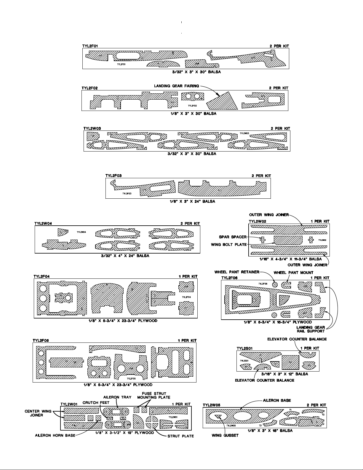
Die Patterns. . . . . . . . . . . . . . . . . . . . . . . . . . . . . . . 6
BUILD THE TAIL SURFACES. . . . . . . . . . . . . . . . . . . . . 7
Build The Fin And Rudder . . . . . . . . . . . . . . . . . . . . 7
Build The Stabilizer And Elevators . . . . . . . . . . . . . . 7
Finish The Tail Surfaces . . . . . . . . . . . . . . . . . . . . . 10
BUILD THE WING . . . . . . . . . . . . . . . . . . . . . . . . . . . . 11
Build The Wing Panels. . . . . . . . . . . . . . . . . . . . . . 11
Join The Wing Panels . . . . . . . . . . . . . . . . . . . . . . 14
Assemble The Ailerons . . . . . . . . . . . . . . . . . . . . . 18
Assemble And Install The Wing Tips. . . . . . . . . . . . 20
BUILD THE FUSELAGE. . . . . . . . . . . . . . . . . . . . . . . . 20
Assemble The Fuselage Sides. . . . . . . . . . . . . . . . 20
Join The Fuselage Sides . . . . . . . . . . . . . . . . . . . . 23
Install The Engine . . . . . . . . . . . . . . . . . . . . . . . . . 27
Sheet The Front Deck . . . . . . . . . . . . . . . . . . . . . . 27
Sand The Fuselage . . . . . . . . . . . . . . . . . . . . . . . . 28
Mount The Wing To The Fuselage . . . . . . . . . . . . . 29
Mount The Stabilizer And Fin. . . . . . . . . . . . . . . . . 29
Install The Dowel Stringers. . . . . . . . . . . . . . . . . . . 31
Mount The Landing Gear . . . . . . . . . . . . . . . . . . . . 33
Assemble The Wheel Pants . . . . . . . . . . . . . . . . . . 33
Assemble The Cowl . . . . . . . . . . . . . . . . . . . . . . . . 35
Construct The Wing Struts . . . . . . . . . . . . . . . . . . . 37
RADIO INSTALLATION . . . . . . . . . . . . . . . . . . . . . . . . 38
Mount The Servos . . . . . . . . . . . . . . . . . . . . . . . . . 38
Install The Throttle Pushrod . . . . . . . . . . . . . . . . . . 40
Install The Aileron Pushrods. . . . . . . . . . . . . . . . . . 40
BALANCE THE AIRPLANE LATERALLY. . . . . . . . . . . 41
FINISHING. . . . . . . . . . . . . . . . . . . . . . . . . . . . . . . . . . 41
Final Sanding. . . . . . . . . . . . . . . . . . . . . . . . . . . . . 41
Cover The Model With MonoKote
®
Film . . . . . . . . . 41
Painting Your Model . . . . . . . . . . . . . . . . . . . . . . . . 42
FINAL HOOKUPS AND CHECKS . . . . . . . . . . . . . . . . 42
Install The Hinges . . . . . . . . . . . . . . . . . . . . . . . . . 42
Install The Wheels . . . . . . . . . . . . . . . . . . . . . . . . . 43
Finish The Model. . . . . . . . . . . . . . . . . . . . . . . . . . 43
Reinstall The Radio System. . . . . . . . . . . . . . . . . . 44
BALANCE YOUR MODEL . . . . . . . . . . . . . . . . . . . . . . 44
SET THE CONTROL THROWS . . . . . . . . . . . . . . . . . . 45
PREFLIGHT . . . . . . . . . . . . . . . . . . . . . . . . . . . . . . . . . 45
Charge The Radio Batteries. . . . . . . . . . . . . . . . . . 45
Balance The Propeller . . . . . . . . . . . . . . . . . . . . . . 45
Find a Safe Place to Fly . . . . . . . . . . . . . . . . . . . . . 46
Ground Check The Model . . . . . . . . . . . . . . . . . . . 46
Range Check Your Radio . . . . . . . . . . . . . . . . . . . . 46
Engine Safety Precautions. . . . . . . . . . . . . . . . . . . 46
AMA SAFETY CODE. . . . . . . . . . . . . . . . . . . . . . . . . . 46
General . . . . . . . . . . . . . . . . . . . . . . . . . . . . . . . . . 46
Radio Control. . . . . . . . . . . . . . . . . . . . . . . . . . . . . 47
FLYING . . . . . . . . . . . . . . . . . . . . . . . . . . . . . . . . . . . . 47
Takeoff . . . . . . . . . . . . . . . . . . . . . . . . . . . . . . . . . . 47
Flight . . . . . . . . . . . . . . . . . . . . . . . . . . . . . . . . . . . 47
Landing . . . . . . . . . . . . . . . . . . . . . . . . . . . . . . . . . 47
2-VIEW DRAWING . . . . . . . . . . . . . . . . . . . . Back Cover
Your T-Craft 20 is not a toy, but rather a sophisticated,
working model that functions very much like an actual
airplane. Because of its realistic performance, the T-Craft
20, if not assembled and operated correctly, could possibly
cause injury to yourself or spectators and damage property.
To make your R/C modeling experience totally
enjoyable, we recommend that you get experienced,
knowledgeable help with assembly and during your fir st
flights. You'll learn faster and avoid risking your model
before you're truly ready to solo.Your local hobby shop has
information about flying clubs in your area whose
membership includes qualified instructors.
You can also contact the national Academy of Model
Aeronautics (AMA), which has more than 2,500 chartered
clubs across the country. Through any one of them,
instructor training programs and insured newcomer training
are available.
Contact the AMA at the address or toll-free phone number
below:
Academy of Model Aeronautics
5151 East Memorial Drive
Muncie, IN 47302-9252
Tele. (800) 435-9262
Fax (765) 741-0057
or via the Internet at http://www.modelaircraft.org
PRO TECT YOUR MODEL,Y OURSELF
& OTHERS...FOLLOW THESE
IMPORTANT SAFETY PRECAUTIONS
TABLE OF CONTENTS
2
Page 3
Since its introduction in the late 1930's, there have been 100's
if not 1000's of the full size T-Craft sold in the U .S.A.They have
come in many versions. Some are very stable, while others
are very aerobatic, like the clipped wing T-Craft. Great Planes
has taken the aerobatic qualities of the full size Clipped Wing
T-Craft and designed them into this .20 sized scale model.
This plane loops, rolls and flies knife edge but still has the
stability of a high wing airplane. So if you’re ready for an easy
building, fun to fly airplane, let's finish reading this introduction
and start building.
While the T-Craft 20 is easy to fly, it does not have the total
self-recovery and stability of a basic trainer like the Great
Planes series of PT™basic trainers. Therefore, if you have
never flown an R/C airplane before, we strongly recommend
that you seek out the assistance of an experienced R/C pilot
who will be able to check out your construction and help you
with your first flights. On the other hand, if you have already
learned the basics of R/C flying, and you are able to safely
handle a low wing airplane, the T-Craft 20 is an excellent
choice to improve your flying skills.
Please inspect all parts carefully before starting to
build. If any parts are missing, broken or defective, or if
you have any questions about building or flying this
airplane, please give us a call at (217) 398-8970 or e-mail
us at productsupport@greatplanes.com and we'll be
glad to help. If you are calling for replacement parts,
please reference the part numbers and have them ready
when calling.
1. Build the plane according to the plans and instructions. Do
not alter or modify the model, as doing so may result in an
unsafe or unflyab le model.In a few cases the instructions may
differ slightly from the photos. In those instances the plans
and written instructions should be considered as correct.
2.Take time to build straight, true and strong.
3.Use an R/C radio system that is in first-class condition.We
highly recommend the use of micro servos on the ailerons
and standard servos on the rudder, elevator and throttle.
4.You must proper ly install all R/C and other components so
that the model operates properly on the ground and in the air.
5. You must test the operation of the model before every
flight to insure that all equipment is operating, and that the
model has remained structurally sound. Be sure to check
clevises or other connectors often and replace them if they
show signs of wear or fatigue.
Remember: Take your time and follow the directions to
end up with a well-built model that is straight and true.
Items in parentheses (GPMQ4243) are suggested part
numbers recognized by most distributors and hobby shops
and are listed for your ordering convenience. GPM is the
Great Planes brand, TOP is the Top Flite®brand, HCA is the
Hobbico®brand and COV is the Coverite™brand.
❏ 4 Channel radio with 3 standard servos and 2 micro servos
❏ (2) 24” extension for aileron servos (HCAM2200)
❏ Y-Harness for aileron servos (HCAM2500)
❏ Engine - See Engine Selection above
❏ Propeller (Top Flite Power Point®); Refer to your engine's
instructions for proper size
❏ Fuelproof paint - see Painting section
❏ Medium fuel tubing 2' (GPMQ4131)
❏ 1/4" Latex foam rubber padding (HCAQ1000)
❏ 6 oz. Fuel tank (GPMQ4102)
❏ Easy Fueler™fuel filling valve (GPMQ4160)
❏ (2) 2-1/2" Wheels (GPMQ4223)
❏ (1) 1" Tail wheel (GPMQ4241)
❏ (2) 3/32" Wheel collars (GPMQ4302)
❏ (4) 5/32" Wheel collar (GPMQ4306)
❏ Pilot (Williams Bros. #18400 1/6 scale spor tsman pilot
used in prototype)
❏ (2) Rolls covering film
❏ Aluminum spinner nut (GPMQ4630)
Required Accessories
PREPARATIONS
ENGINE SELECTION
Recommended engine size:
.25 to .32 cu. in. 2-stroke
.26 to .30 cu. in. 4-stroke
Your Great Planes T-Craft 20 will perform well with any of
the engines within the recommended range.
DECISIONS YOU MUST MAKE
PRECAUTIONS
Note: We, as the kit manufacturer , pro vide y ou with a top
quality kit and great instructions, but ultimately the quality
and flyability of your finished model depends on how y ou
build it; therefore, we cannot in any way guarantee the
performance of your completed model, and no
representations are expressed or implied as to the
performance or safety of your completed model.
INTRODUCTION
3
Page 4
4
These are the building supplies that are required.
We
recommended Great Planes Pro™CA and Epoxy glue.
❏ 1 oz.Thin Pro CA (GPMR6002)
❏ 1 oz. Medium Pro CA (GPMR6008)
❏ 6-Minute Pro Epoxy (GPMR6045)
❏ 30-Minute Pro Epoxy (GPMR6047)
❏ Thread locking compound (GPMR6060)
❏ Balsa filler (HCAR3401)
❏ Canopy Glue
❏ Plan protector (GPMR6167)
❏ Isopropyl rubbing alcohol (70%)
❏ Paper towels
❏ Sanding block and sandpaper (coarse, medium, fine)
❏ Hobby knife (HCAR0105)
❏ #11 blades (HCAR0211)
❏ Single-edge razor blades (HCAR0212)
❏ Razor saw
❏ Razor plane (MASR1510)
❏ Electric drill
❏ Drill bits - 1/16",3/32", 5/32", 3/16", 13/64", 7/32”, 1/4"
❏ Small Phillips and flat blade screwdrivers
❏ Pliers with wire cutter (HCAR0630)
❏ Sealing Iron (TOPR2100)
❏ Heat gun (TOPR2000)
❏ T-Pins (HCAR5150)
❏ Straightedge with scale (HCAR0475)
❏ Cutting mat (HCAR0456)
❏ Builder's triangle (HCAR0480)
❏ 1/4-20 Tap and Drill set (GPMR8105, drill bit included)
❏ Tap handle (GPMR8120)
❏ Masking Tape (TOPR8018)
❏ Monofilament string for aligning the wing and stabilizer
❏ Panel line pen (TOPQ2510)
❏ Groove Tube (GPMR8140)
❏ Dead Center Hole Locator (GPMR8130)
❏ Precision Hinge Marking Tool (GPMR4005)
❏ Microballoons (TOPR1090)
❏ CG Machine™(GPMR2400)
❏ Accu Throw®Deflection Meter (GPMR2405)
❏ CA Applicator tips (HCAR3780)
❏ CA Debonder (GPMR6039)
❏ Clevis installation tool (GPMR8030)
❏ Hot Sock™(TOPR2175)
❏ Curved-Tip canopy scissors (HCAR0667)
❏ Top Flite Precision Magnetic Prop Balancer™(TOPQ5700)
❏ Slot Machine™motorized hinge slotting tool (GPMR4010)
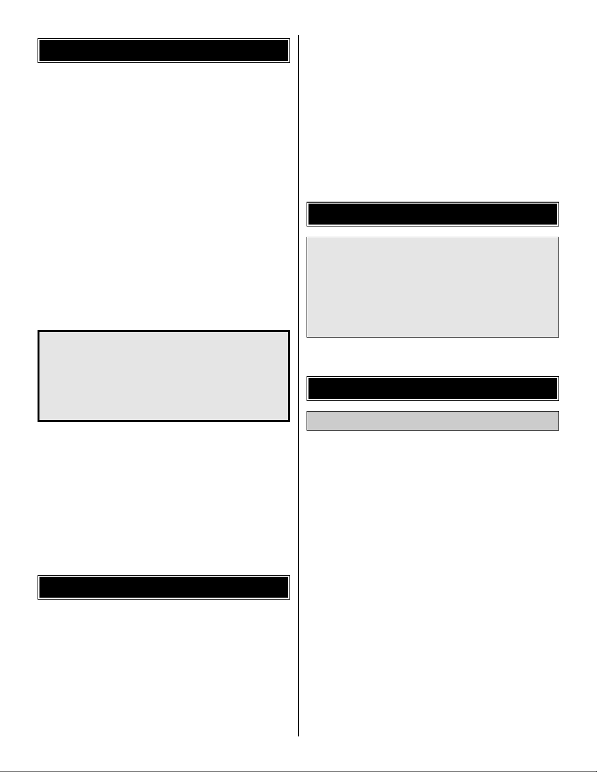
On our workbench, we have three 11" Great Planes EasyTouch™Bar Sanders, equipped with #80, #150 and #220grit sandpaper.This setup is all that is required for almost
any sanding task.We also keep some #320-grit wet-or-dry
sandpaper handy for finish sanding before covering.
Great Planes Easy-Touch Bar Sanders are made from
lightweight extruded aluminum and can be found at most
hobby shops. They are available in five sizes – 5-1/2"
(GPMR6169) for those tight, hard-to-reach spots; 11"
(GPMR6170) for most general purpose sanding; and 22"
(GPMR6172), 33" (GPMR6174) and 44" (GPMR6176) for
long surfaces such as wing leading edges. The Easy-
Touch Adhesive-Backed Sandpaper comes in 2" x 12'
rolls of 80-grit (GPMR6180), 150-grit (GPMR6183) and
220-grit (GPMR6185) and an assortment of 5-1/2" long
strips (GPMR6189) for the short bar sander.The adhesivebacked sandpaper is easy to apply and remove from your
sanding bar when it's time for replacement.
This setup is all that is required for almost any sanding task.
Custom sanding blocks can be made from balsa or hardwood
blocks and dowels for sanding difficult-to-reach spots.
Fuse = Fuselage
LE = Leading Edge (front)
TE = Trailing Edge (rear)
Stab = Stabilizer
" = Inches
Elev = Elevator
LG = Landing Gear
Ply = Plywood
Common Abbreviations
Optional Supplies and Tools
Tools
Building Supplies
Page 5
1. Unroll the plan sheets, then re-roll the plans inside-out to
make them lie flat.
2. Sort through the sticks and sheets, grouping them by
size. Masking tape can be used to bundle matching sheets
and sticks. Using a felt tip or ballpoint pen, lightly write the
part name or size on each piece or bundle. Refer to the
parts list and plans for sizes and quantities. Use the die-cut
patterns shown on page 6 to identify the die-cut parts and
mark them before removing them from the die sheet. Save
all leftovers.If any of the die-cut parts are difficult to remov e,
do not force them! Instead, cut around the parts with a
hobby knife or lightly sand the back of the sheet. After
removing the die-cut parts, use your sanding block to lightly
sand the edges to remove any die-cutting irregularities.
3. As you identify and mark the par ts, separate them into
groups, such as fuse (fuselage), wing, fin, stab (stabilizer)
and hardware.
Zipper-top food storage bags are handy to store the small
parts as you sort, identify and separate them into
sub-assemblies.
4.Work on a flat surface.Cover the plans with waxed paper
or Great Planes Plan Protector to prevent glue from stic king
to the plan.
5.When instructed to test fit parts, this means DO NOT USE
GLUE until you are satisfied that everything fits properly --
THEN glue the parts together if instructed to do so.
6. Whenever the instructions tell you to glue pieces
together, use CA.When a specific type of glue is required,
the instructions will state the type of glue that is highly
recommended. When 30-minute epoxy is specified, it is
highly recommended that you use only 30-minute (or
slower) epoxy because you will need either the working
time and/or the additional strength.
7. The easiest way to cut balsa sticks is with a single-edge
razor blade or razor saw. Position the stick over the plan,
mark its size, then cut the part on a cutting mat. A modeling
miter box works well for cutting square corners and 45degree gussets.
IMPORTANT BUILDING NOTES
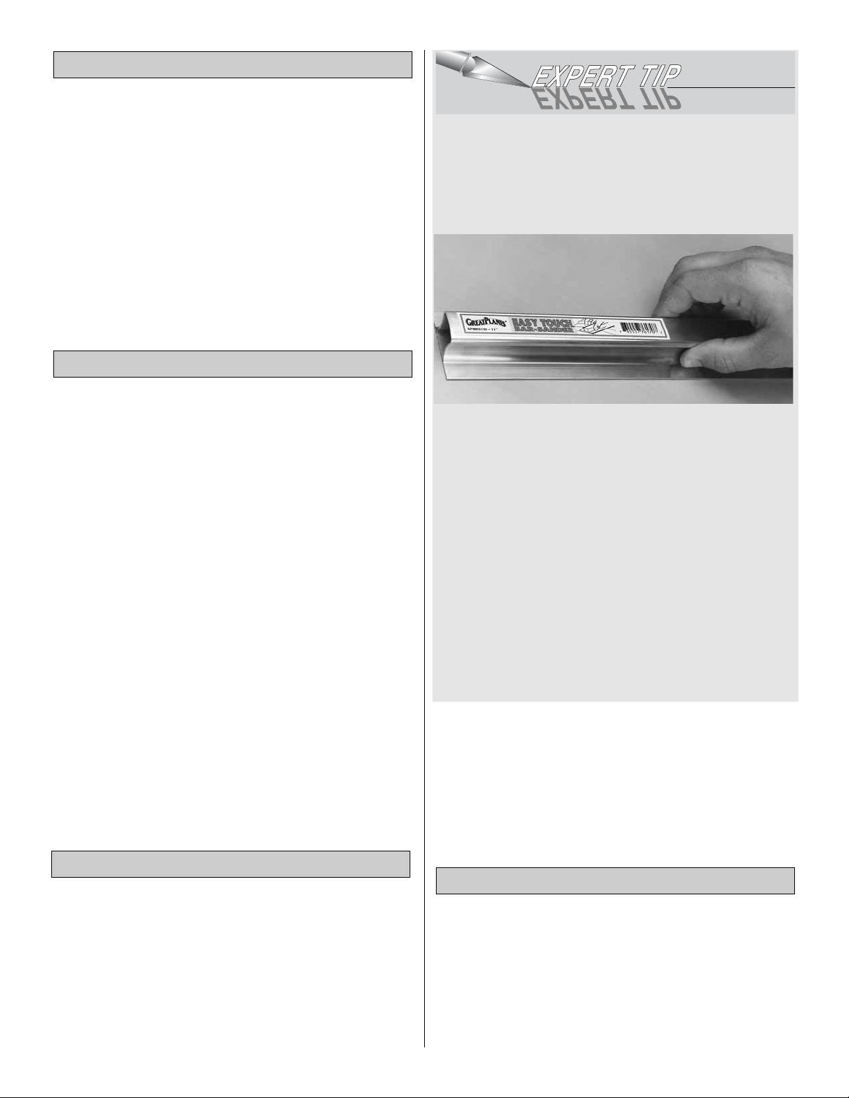
Types of Wood
5
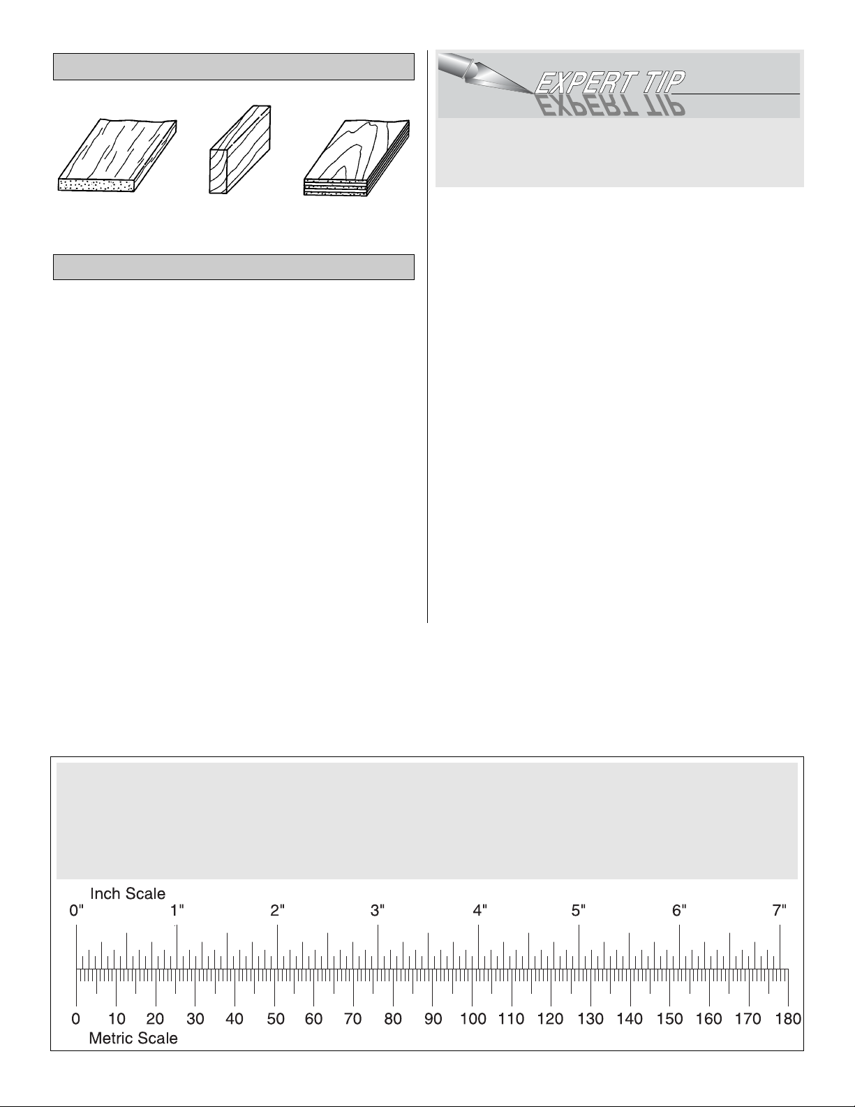
Metric Conversions
1/64" = .4 mm
1/32" = .8 mm
1/16" = 1.6 mm
3/32" = 2.4 mm
1/8" = 3.2 mm
5/32" = 4.0 mm
3/16" = 4.8 mm
1/4" = 6.4 mm
3/8" = 9.5 mm
1/2" = 12.7 mm
5/8" = 15.9 mm
3/4" = 19.0 mm
1" = 25.4 mm
2" = 50.8 mm
3" = 76.2 mm
6" = 152.4 mm
12" = 304.8 mm
18" = 457.2 mm
21" = 533.4 mm
24" = 609.6 mm
30" = 762.0 mm
36" = 914.4 mm
Page 6
6
DIE-CUT PATTERNS
Page 7
❏ 1. Cover the fin/rudder portion of the plan with wax paper
or Great Planes Plan Protector.
❏ 2. Pin the die-cut 3/16" balsa fin frame V-1 in position on
the fuse plan.
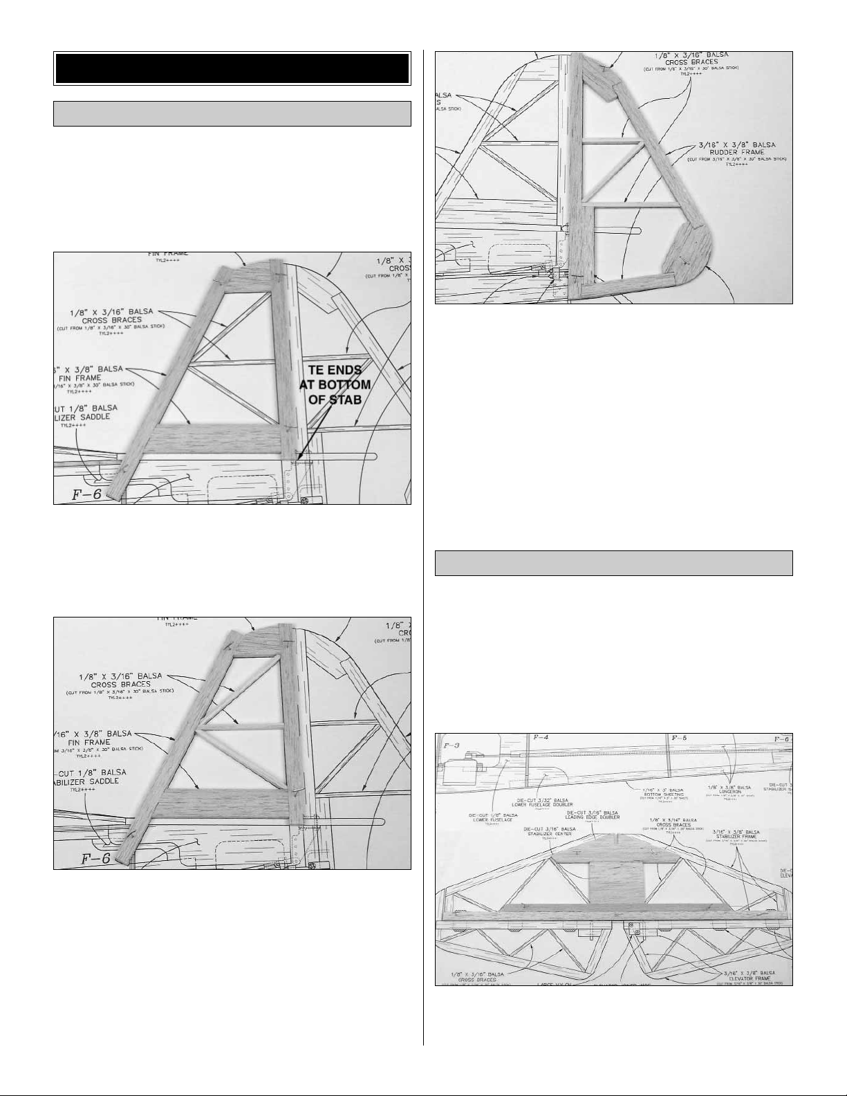
❏ 3. From one of the 3/16" x 3/8" x 30" balsa sticks, cut and
glue the fin frame together. Note that there are two pieces
along the bottom of the fin and that the TE ends at the
bottom of the stabilizer.
❏ 4. From the 1/8" x 3/16" x 30" balsa stick, cut and glue the
fin cross braces to the frame.
❏ 5. Remove the fin from your building board.Inspect all the
glue joints and add CA to any joints that don't look strong.
Fill any gaps with balsa sanding dust and a drop or two of
thin CA.
❏ 6. Build the rudder frame from the die-cut 3/16" balsa
R-1 and R-2 frame pieces and leftover 3/16" x 3/8" balsa stick.
❏ 7. From the leftover 1/8" x 3/16" balsa stick, cut and glue
the rudder ribs and cross brace to the frame.
❏ 8. Remove the rudder from your building board.Inspect all
the glue joints and add CA to any joints that don't look strong.
First, sand both sides of the rudder and fin flat and even.
Then, sand the rudder and fin to shape using the fuse plan
as a guide. Be careful that you don't sand any area too thin.
❏ 1. Cover the stabilizer/elevator portion of the plan with
waxed paper or Plan Protector.
❏ 2. From one of the 3/16" x 3/8" x 30" balsa sticks, cut the
stabilizer trailing edge and trailing edge doubler to
match the stabilizer plan.Glue the TE doubler to the TE and
pin them over the plan.
❏ 3. Pin the die-cut 3/16" balsa leading edge doubler S-1
and stab center S-2 in position. Glue S-2 to S-1 and to the
front of the stab TE doubler.
Build the Stabilizer & Elevators
Build the Fin & Rudder
BUILD THE T AIL SURF ACES
7
Page 8
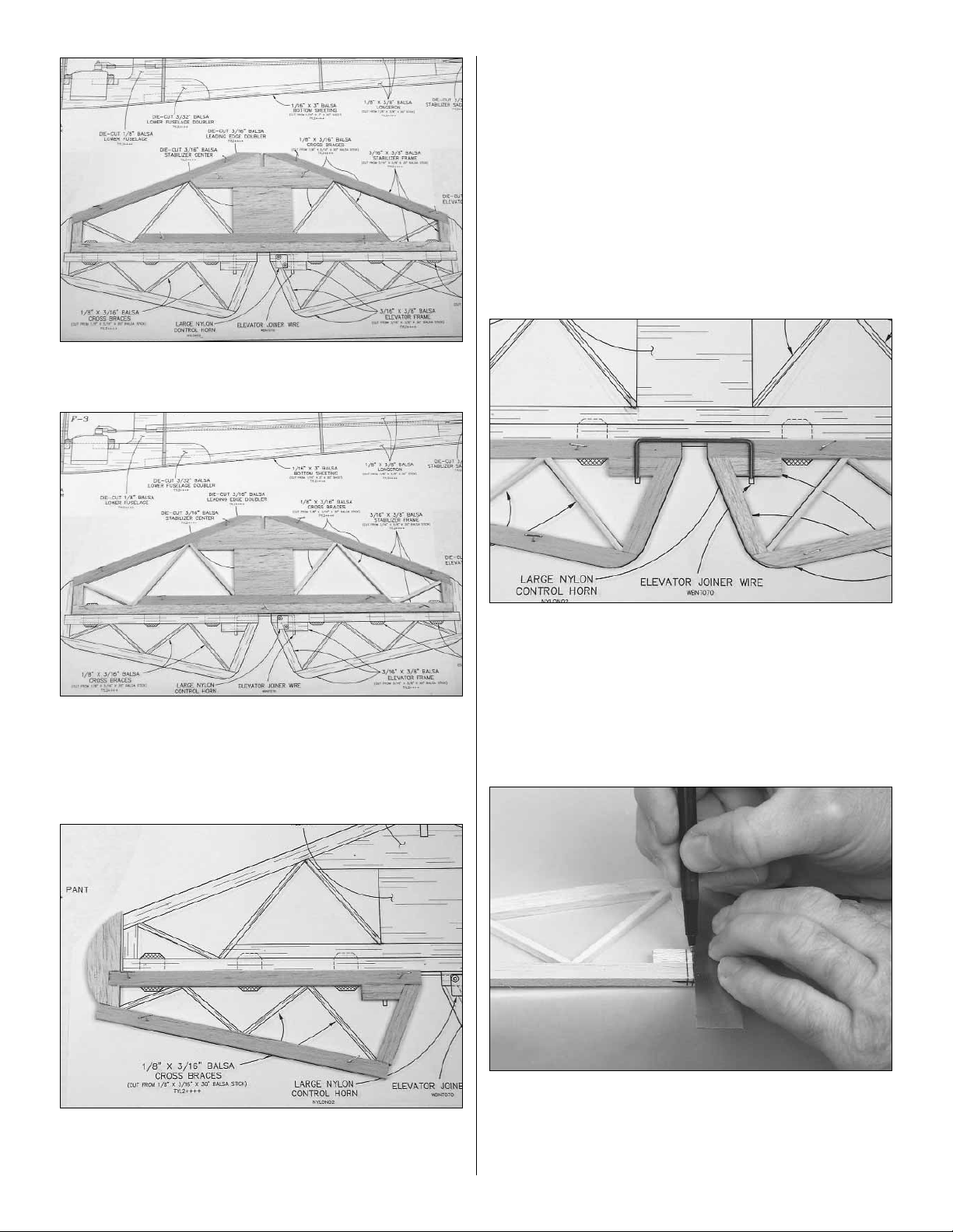
❏ 4. Finish constructing the stab frame from a 3/16" x 3/8" x
30" balsa stick.
❏ 5. From the 1/8" x 3/16" x 30" balsa stick, cut and glue the
stab braces to the stab frame.
❏ 6. Remove the stab from your building board. Inspect,
glue and sand as you did with the fin.
❏❏7.From a 3/16" x 3/8" x 30" balsa stick, cut the elevator
leading edge to length and pin it over the elevator plan.Pin
and glue the die-cut 3/16" balsa elevator counter balance
to the LE. Construct the remaining elevator frame from a
3/16" x 3/8" x 30" balsa stick.
❏❏8. From the 1/8" x 3/16" x 30" balsa stick, cut and glue
the elevator cross braces to the frame.
❏ 9. Repeat steps 7 and 8 to build the second elevator half.
❏ 10. Remove the elevators from your building board.
Inspect, glue and sand as you did with the fin.
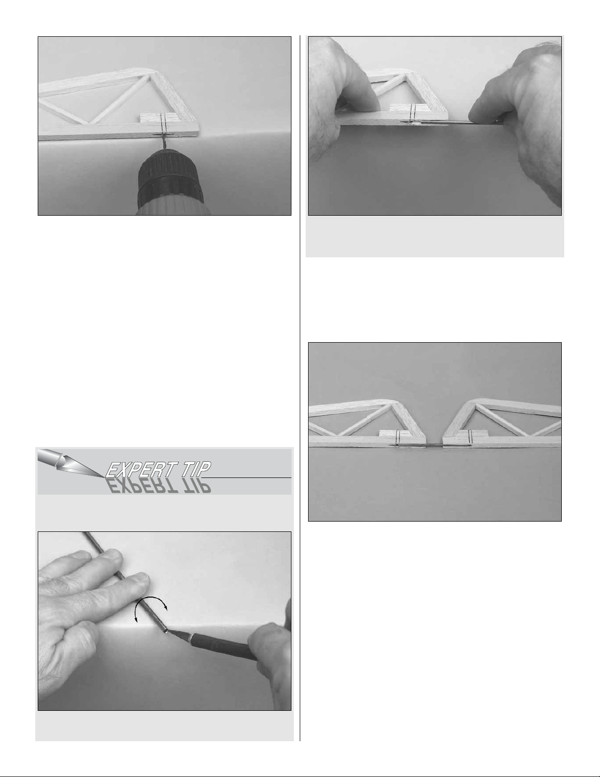
❏ 11. Pin both elevators in position over the plan. Lay the
3/32" elevator joiner wire on top of the elevators in the
position shown on the plan. Use a pencil to lightly mar k the
outline of the joiner wire on the elevators.
❏ 12. Using a straightedge, extend the sidelines of the
elevator joiner outline forward to the leading edge.Also, use
a Precision Hinge Marking Tool to draw a centerline on
the leading edge. Using these lines, you can determine
exactly where to drill the holes for the elevator joiner wire.
8
Page 9
❏ 13. Drill a 3/32" hole into the leading edge of both
elevators. As you drill each hole, keep the drill aligned with
the top and bottom surface of the elevator and reference
lines you made in the previous steps.
❏ 14. Use the Great Planes Groove Tube to cut a 3/32"
groove in the leading edge of both elevators to recess the
joiner wire. Note: If you do not have a Groove Tube, refer to
the Following Expert Tip.
HOW TO CUT A GROOVE FOR A JOINER WIRE
A. Use a #11 knife blade to sharpen the inside of a piece
of 3/32" brass tube. Roll the tube as you carve the end.
B. Use the sharpened tube to carefully gouge the leading
edge of the elevators. You'll have to make several shallow
passes to make the recess deep enough for the joiner wire.
❏ 15. Temporarily join the elevators with the joiner wire.The
joiner wire will be easier to install if you chamfer (bevel) the
ends a little. If necessary, “tweak” the joiner wire so the
elevators are parallel and la y flat on y our building tab le when
the joiner wire is installed. If you found it necessary to
“tweak” the joiner wire, use a felt-tip pen to mark it so you
can install the joiner wire in the same orientation when you
permanently join the elevators.
❏ 16. Lay the elevators and stab over the plan and lightly
mark the hinge locations on the LE of the elevators and the
TE of the stab. Repeat the process to mark the hinge
locations on the LE of the rudder and TE of the fin.
9
Page 10
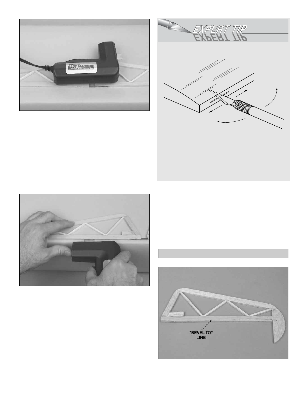
We have simplified the task of cutting hinge slots with the
introduction of the Great Planes Slot Machine™. This
electric tool easily cuts a perfect width slot for use with CA
hinges every time.
❏ 17. To cut the hinge slot, place the blades onto the wood
where you want the slot. Lightly press the teeth into the
wood. When you are satisfied with the location, press the
button on the handle and the blades will cut easily into the
balsa wood.
If you choose not to purchase a Slot Machine, refer to the
Expert Tip that follows to make hinge slots.
Cut the hinge slots in the elevators, stabilizer, fin and
rudder using a Hobby Knife with a #11 blade. Begin by
carefully cutting a very shallow slit at the hinge location to
accurately establish the hinge slot. Make three or four
more cuts, going a little deeper each time.As you cut, slide
the knife from side to side until the slot has reached the
proper depth and width for the hinge.
❏ 18. Cut the 3/4" x 1" hinges for the elevator and rudder
from the supplied 2" x 9" hinge material, then snip off the
corners. Temporarily join the elevators to the stab and the
rudder to the fin with the hinges, adjusting any hinge slots if
necessary so they all align.Do not glue in the hinges until
you are instructed to do so.
❏ 1.Use a Precision Hinge Marking Tool to mark the
centerline on the LE of the elevator.Mark a “bevel to”line on
both sides of the elevator LE, about 3/32" from the LE.
Finish the Tail Surfaces
CUT HINGE SLOT
WITH HOBBY KNIFE
AND #11 BLADE
10
Page 11
❏ 2. Using the “bev el to”lines and the centerline as a guide,
make the “V” on the leading edge of the elevators with a
razor plane or your bar sander with 150-grit sandpaper.
❏ 3. Use the same procedure to bevel the leading edge of
the rudder.
❏ 4. Temporarily attach the elevators to the stab and the
rudder to the fin.Use your bar sander to round the perimeter
of the elevator, stab, rudder and fin (do not round the bottom
edge of the fin where it will be glued to the stab and fuse).
Start by building the right wing panel right side up over the
right wing panel plan so your progress matches the photos.
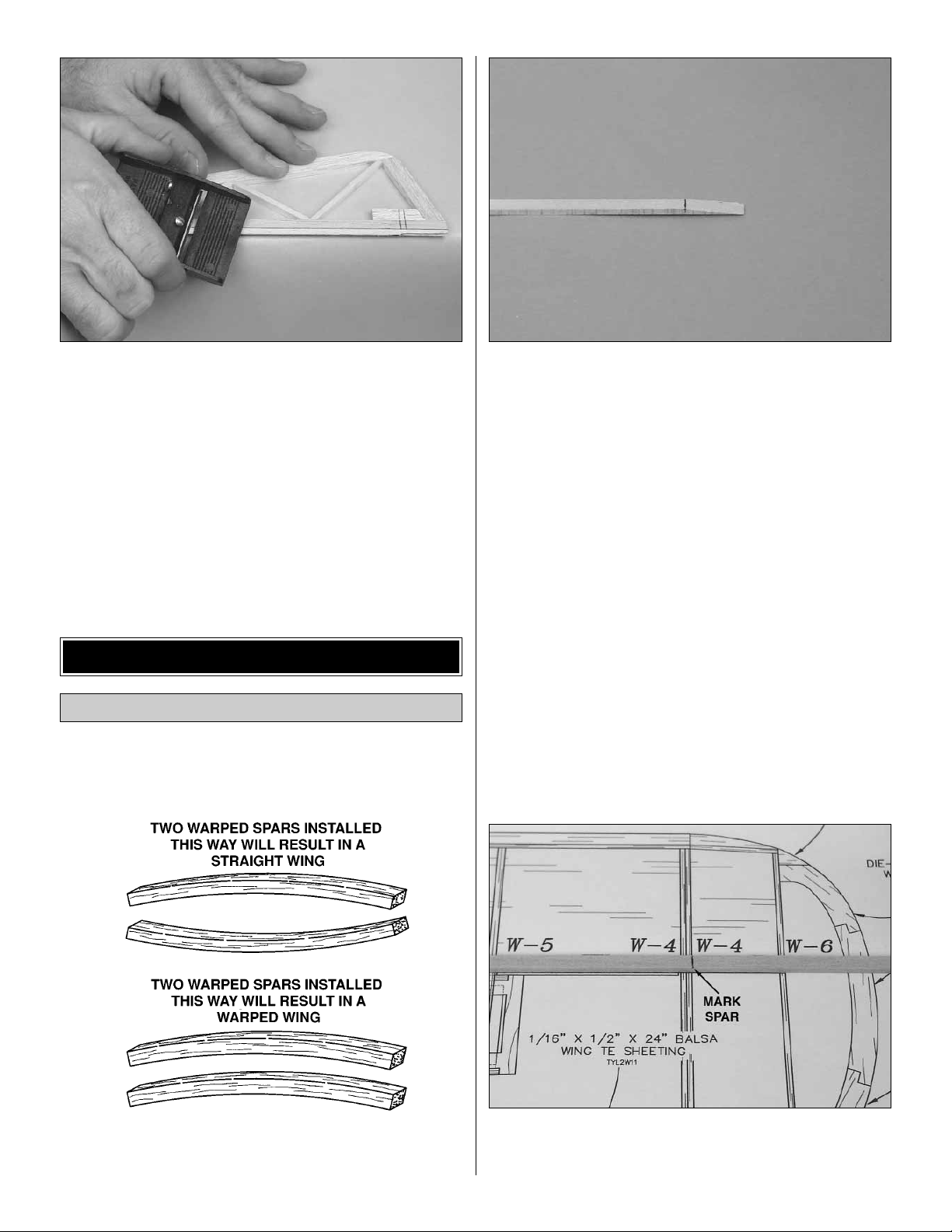
❏ 1. Match the six 1/8" x 1/4" x 30" basswood main spars
so any warps will counteract each other.
❏ 2. Cut two of the main spars in half. Draw a line 1" from
one end of each of the 15" half spars and bevel the end of
the spars to the line.
❏ 3. Use epoxy to glue the four 15" main spars onto the four
30" main spars, as shown on the plans.Make sure the sides
and ends of the spars are flush with each other.Wipe off any
excess epoxy before it cures.
❏❏4.Cover the wing panel plan with waxed paper or Great
Planes Plan Protector.
❏❏5.Position one of the main spars over the plan, aligning
the double spar end of the main spar with the outboard edge
of the root rib W-1.Mark the spar at the tip side of ribs W-4.
Build the Wing Panels
BUILD THE WING
11
Page 12
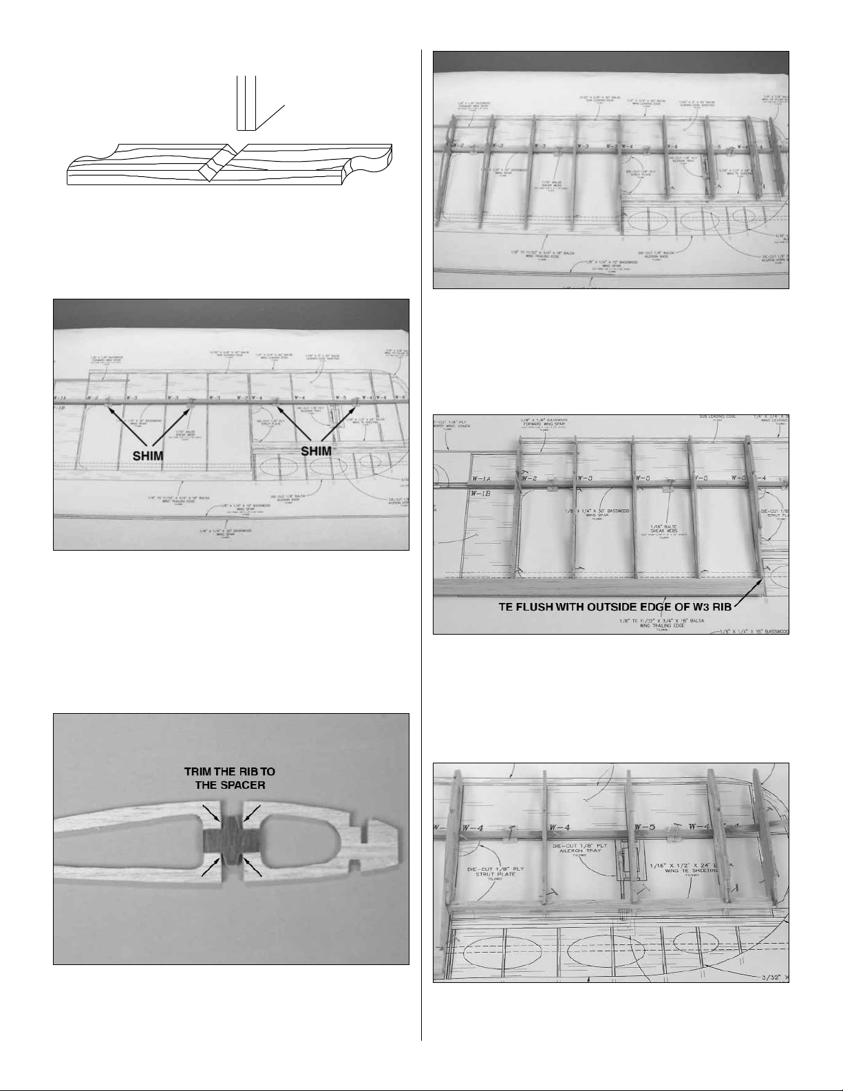
❏❏6.Cut a V-notch part way through the spar , at the mark,
so that the spar can bend at W-4.
❏❏7.From one of the 1/16" x 3" x 30" balsa sheets, cut four
1/2" x 3/4" shims. Place the shims over the spar location on
the plan, starting between ribs W-2 and W-3 and alternating
every other rib bay. Pin the main spar, cut in step 6, over the
shims, aligned with the wing plan at the wing root.
❏❏8. Glue two of the die-cut 3/32" balsa W-4 ribs together
to make the W-4 outer rib.
❏❏9.Glue the die-cut 1/16" ply W-2 spar spacer to the tip
side of rib W-2, centered between the main spar notches
and the lightening holes.Tr im the main spar notches for the
1/16" plywood wing joiner.
❏❏10. Pin and glue the die-cut 3/32" balsa W-2,W-3, W-4
and W-6 ribs and the die-cut 1/8" balsa W-5 rib onto the
main spar, perpendicular to the building board.Note: There
is a W -3 and W-4 rib glued together at the root of the aileron
bay. The main spar will need to be bent upward to contact
the W-6 rib.
❏❏11.Position the 1/8" to 11/32" x 3/4" x 18" shaped balsa
trailing edge on the jig tabs of the W-2 and W-3 ribs, flush
with the outside of rib W-3.Use a straight edge to align the
top of the TE with the top of the ribs.When satisfied with the
fit, glue the TE to the ribs.Note: The TE extends 1/16" abo v e
rib W-2 to allow for the 1/16" center sheeting.
❏❏12. Fit and glue the 1/4" x 1/4" x 30" balsa sub TE in
the notches at the rear of the W -4 and W -5 ribs.Butt glue the
sub TE to rib W-6.
W4
W4
1/8" X 1/4" MAIN SPAR
12
Page 13
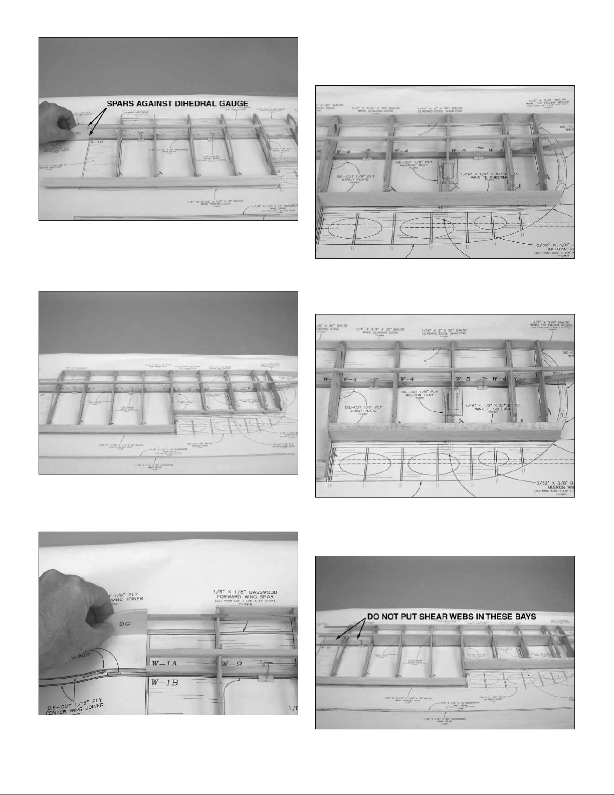
❏❏13. Hold the die-cut 1/8" plywood dihedral gauge
against the root end of the bottom main spar.With the root
end of the top main spar against the dihedral gauge, insert
and glue the spar into the notches in the top of the ribs.
❏❏14.Center the 3/32" x 5/8" x 30" balsa sub LE on the front
of the ribs.Check that the jig tabs at the aft end of the ribs are
against the building board.Then, glue the sub LE in position.
❏❏15.From the 3/16" x 3/16" x 24" basswood stic k, cut two
forward spars 6" long. Align the dihedral gauge with the
centerline of the wing. Glue the forward spars in the top and
bottom of ribs W-2 and W-3 with the root ends against the
dihedral gauge. Make sure that these forward spars are
against the back edge of the slot in W-2.
❏❏16.Cut the 3/32" x 7/8" x 24" balsa stick in half to make
the aileron bay TE. Glue one of the TE pieces, centered, on
the aft end of the W-4 through W-6 ribs and the sub TE.
❏❏17. Cut one of the 1/16" x 1/2" x 24" balsa TE sheets in
half.Test fit the TE sheet in the recess at the aft end of the
W-4 through W-6 ribs and trim as necessary.
❏❏18. From the 1/16" x 3" x 30" balsa sheet, cut and glue
vertical grain shear webs to the spars in the locations
13
Page 14
shown on the plan.It is not necessar y for the shear webs to
be glued to the ribs. Make sure they are glued securely to
the wing spars. Do not install shear webs in the rib bays
between ribs W-1 and W-3.
❏❏19. Use the dihedral gauge to mark the TE at the wing
center.Trim the TE along the line.
❏❏20. Remove the wing from your building board and
install the second piece of 1/16" x 1/2" TE sheet on the
bottom of the wing. Note: The TE sheet will need to be bent
to meet rib W-6.
❏ 21. Return to step 4 and build the left wing panel.
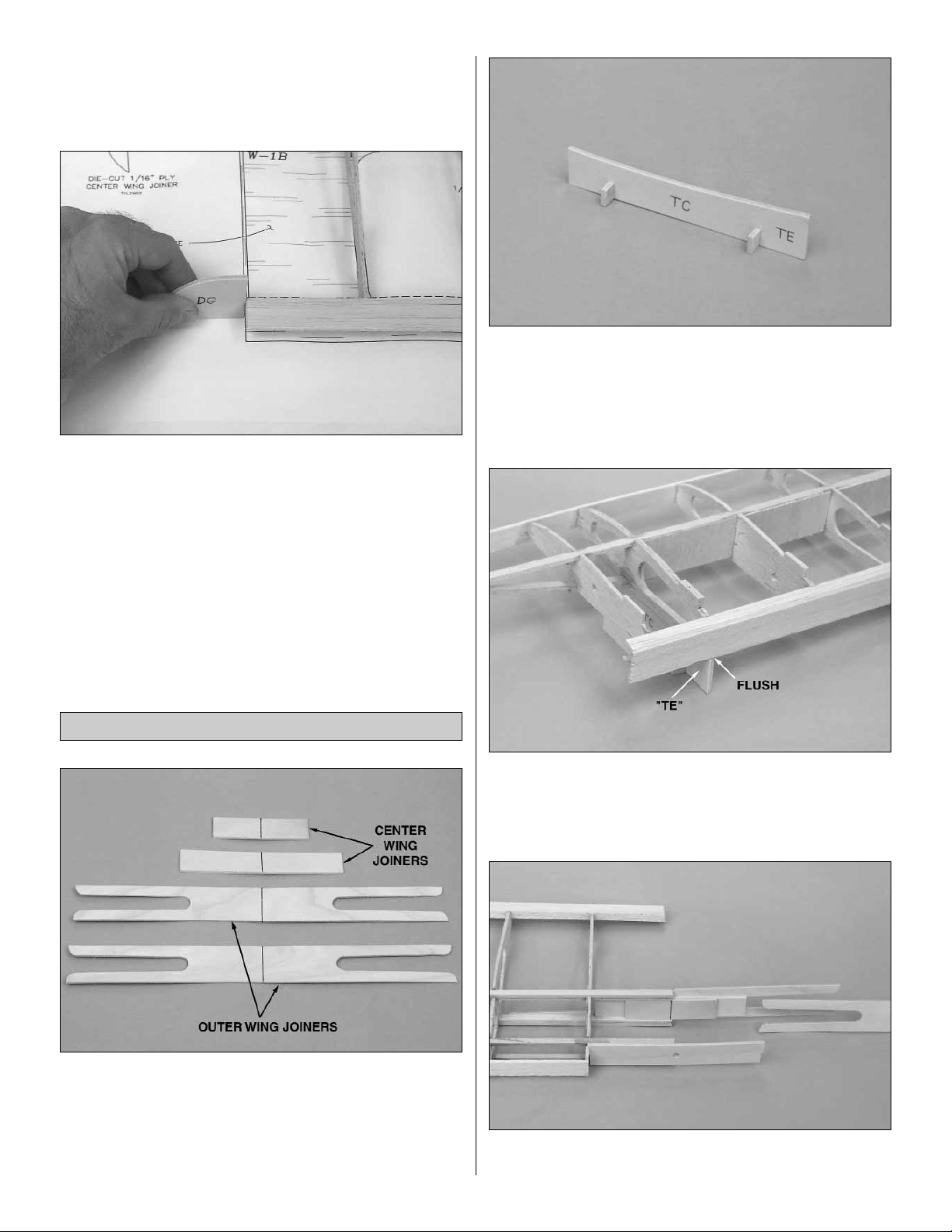
❏ 1. Draw a centerline on the two die-cut 1/8" plywood
center wing joiners and the two die-cut 1/16" plywood
outer wing joiners.
❏ 2. Use epoxy to glue the two center wing joiners together,
aligning the centerlines and the edges.
❏ 3.Assemble the die-cut 1/8" plywood wing tip crutch and
crutch feet. Do not glue the feet to the tip crutch.
❏ 4. Trim the jig tabs off the bottom of the double W-4 ribs
on the left wing panel.Sand the bottom of the ribs, TE sheet
and aileron bay TE flush on the left wing panel.
❏ 5. Position the left wing panel on your flat building board.
Place the wing tip crutch under the double W-4 ribs. The
“TE” on the tip crutch should be toward the TE and the
crutch should be flush with the TE.
❏ 6. Insert the center wing joiners between the main spars,
the outer wing joiners on the front and back of the main wing
Join the Wing Panels
14
Page 15
spars and the die-cut 1/8" plywood forward joiner in the
right wing. Slide the r ight wing half with the joiners into the
left wing half, checking the fit.The main spars, forw ard spars
and TE on both wing halv es should meet.Make sure the left
wing half is positioned on the tip crutch and the right wing
half is flat against your building board. Sight down the wing
from the wing tip, checking that the main spar, sub LE and
TE are straight. If they are not, lightly sand the ends of the
spars or TE to achieve a straight wing. Caution: Remove
only a small amount at a time.You can always remove more
wood, but cannot add more wood once it’s removed.
❏ 7. When satisfied with the fit of the wing halves, remove
the joiners. Use 30-minute epoxy to glue the two wing
halves together. Apply epoxy to the top and bottom of the
center wing joiners, the front and back sides of the main
spars, the front of the forward spars , the ends of the forward
joiner and the TE's.Slide everything back together.Wipe off
any excess epoxy with a paper towel dampened with
rubbing alcohol. Check that the tip crutch is in position, the
right wing panel is flat against your building board and the
main spar is straight. Use clamps to hold the joiners in
position until the epoxy cures.
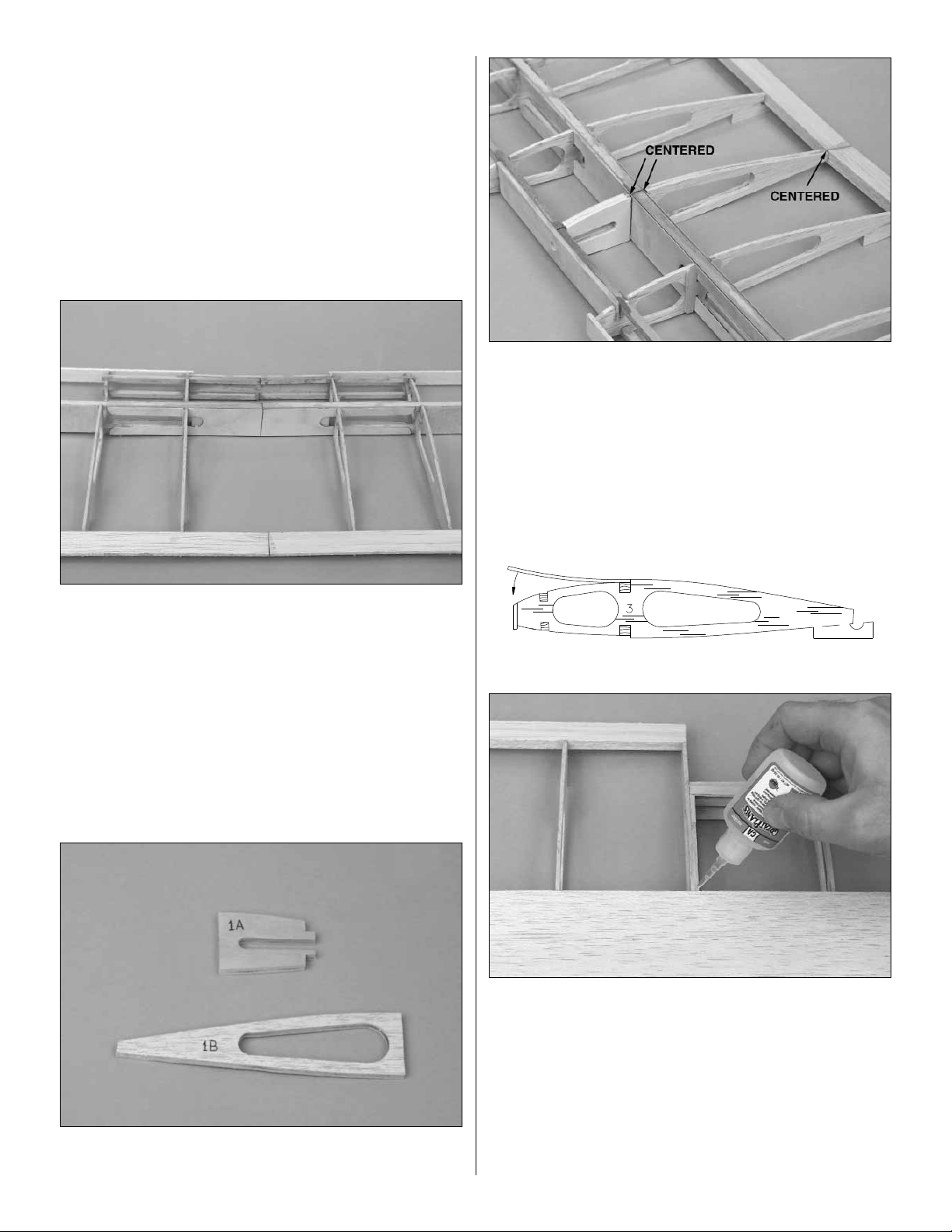
❏ 8. Glue together the two die-cut 1/8" plywood ribs W-1A
and the two die-cut 3/32" balsa ribs W-1B.
❏ 9. Use epoxy to glue the W-1A ribs to the forward spars
and forward joiner, centered on the ply wing joiner. Glue
W-1B, centered on the ply wing joiner and the TE.
❏ 10. Glue shear webs to the aft side of the ply wing joiner
between ribs W-2 and W-3.
❏ 11. Sand the balsa sub LE flush with the top of the ribs.
❏ 12. Support one wing panel with the wing tip cr utch and
weight the other panel flat on your building board. On the
weighted panel, fit a 1/16" x 3” x 30” balsa sheet in place,
against the notch in the ribs and on top of the main spar and
over one of the W-1A ribs.Glue the balsa sheet to the main
spar and notches. When the glue has cured, apply a bead
of glue to the top of each rib, along the sub LE and forward
spar and joiner. Pull the sheeting down, making sure it
contacts the surface of each rib, sub LE and forward spar
and joiner.Hold it in place until the glue has cured.
15
Page 16

❏ 13. After the glue has cured, switch the tip crutch to the
other wing panel and repeat the sheeting process.
❏ 14. Sheet the center section using a 1/16" x 3" x 30"
balsa sheet.
❏ 15. Trim and sand the sub LE, top wing sheeting, main
spars and TE sheeting flush with the W-6 rib.Trim the wing
sheeting flush with the forward joiner.
❏ 16. Sand the balsa sub LE flush with the bottom of the
ribs and remove the bottom jig tabs from the bottom of all
the ribs. Note: The sub LE tapers at rib W-6.
❏ 17. Remove the crutch feet from the wing tip crutch and
install them on the die-cut 1/8" plywood center crutch (CC).
❏ 18. Position the wing upside down on your building board,
supported by the jig tabs on ribs W-6 and the center crutch
at the center of the wing.The “F” on the center crutch goes
to the front.
❏ 19. Locate the 1/4" x 2-1/4" hardwood wing dowel. Round
both ends of the dowel for ease of insertion. Test fit the 1/4"
dowel in the forward wing joiner and rib W-1A.Use a 1/4" drill
bit to clean out the hole if needed.Use epoxy to glue the dowel
in the forward wing joiner and W-1A as shown on the plans.
❏ 20. Sheet the bottom of the wing following the same
procedure used to sheet the top of the wing. Note: A
separate piece of 1/16" balsa sheeting is used to sheet
between the double W-4 ribs and rib W-6.
❏ 21. Trim and sand the 1/16" bottom wing sheeting flush
with rib W-6, the forward wing joiner and the sub TE.
❏ 22. Glue the 1/4" x 3/4" x 30" balsa leading edg e to the
sub LE and wing sheeting.
16
Page 17

❏ 23. Use a razor plane and sanding bar to shape the LE to
the shape shown on the wing plan.
❏ 24. Remove the jig tabs from the top of the ribs. Use a
sanding bar to sand the entire wing smooth.
❏ 25. Draw a centerline on the die-cut 1/16" plywood wing
bolt plate.
❏ 26. Use a sanding bar to bevel the front and sides of the
wing bolt plate to a sharp edge.
❏ 27. Use 6-minute epoxy to glue the wing bolt plate on the
top of the wing, aligning the centerline on the plate with the
centerline of the wing and flush with the TE. Use masking
tape or clamps to hold it tight against the wing sheeting until
the epoxy cures.
❏❏28. Complete the partial die-cutting of the aileron servo
bay in rib W-5.
❏❏29.Test fit the die-cut 1/8" plywood aileron servo tray
sides and top in the aileron servo bay. Lay a straightedge
across the top of the servo tray from the forward wing
sheeting to the TE sheeting. Position the aileron servo tray
so that it is flush with the forward and TE sheeting. When
positioned correctly, glue the servo tray sides to W-5 and
shear webs and the top of the tray to the sides of the tray.
❏❏30. Glue the die-cut 1/8" balsa gusset in the corner of
the outside rib W-3 and the shaped TE.
17
Page 18

❏❏31.Glue the two die-cut 1/8" ply wing strut plates to the
W-4 ribs, main spar and aileron TE sheet in position. The
wing strut plates must be flush with the bottom of the wing.
❏ 32. Go back and repeat steps 28 through 30 on the other
wing half.
❏❏1. Position the die-cut 1/8" balsa aileron base over the
plan. Mark the aileron rib locations on both sides of the
aileron base.
❏❏2. Cut the 3/8" x 1" x 24" balsa aileron LE in half. Draw
a centerline lengthwise on the 1" x 12" side.
❏❏3. Glue the aileron base on the aileron LE along the
centerline and perpendicular to the face of the LE.
❏❏4.From the 3/32" x 3/8" x 30" balsa sticks, cut and glue
aileron ribs to both sides of the aileron base, perpendicular
to the base.
❏❏5. Trim the ends of the aileron LE flush with the
aileron base.
❏❏6. From a leftover piece of 1/16" sheeting, cut and glue
a root rib to the root of the aileron.
❏❏7.Place a piece of leftover 1/16" balsa between the root
rib of the aileron and the outside W-3 rib .Use a straightedge
to align the TE of the wing with the TE of the aileron.Then,
securely pin the aileron to the wing.
Assemble the Ailerons
18
Page 19

❏❏8. Use a razor plane and sanding bar to shape the
aileron ribs and LE to shape.
❏❏9. From the leftover 1/4" x 1/4" balsa stick, cut and glue
an aileron LE doubler behind the aileron LE, between the
ribs that are in line with the aileron servo tray.
❏❏10.Position the die-cut 1/8" plywood ailer on horn base
on the aileron LE and LE doubler. Mark the outline of the
base on the LE and doubler.
❏❏11.Mark the location of the hinges on the aileron and wing.
❏❏12. Remove the aileron from the wing and trim the
aileron LE and LE doubler to recess the aileron horn base
flush with the top of the aileron ribs and LE. When satisfied
with the fit, glue the aileron horn base to the LE, LE doubler
and aileron rib.
❏❏13. Draw a centerline on the LE of the aileron and the
TE of the aileron bay. Note: The centerline is not centered
at the tip of the aileron.
❏❏14. Cut the hinge slots in the aileron and the wing. Cut
three 3/4" wide hinges from the supplied hinge strip and trim
the corners. Insert the hinges in the aileron and fit the
aileron to the wing. Do no glue until told to do so.
❏❏15. Remove the aileron from the wing. Mar k the “bevel
to” lines on both sides of the aileron, 3/16" from the LE.
Shape the LE of the aileron to a “V” as shown on the plan.
❏❏16. Check the fit of the aileron on the wing. The aileron
should have 3/4" to 1" of throw each way.
❏ 17. Return to step 1 of
Assemble the Ailerons
and build
the second aileron.
19
Page 20

❏❏1. Cover the wing tip portion of the wing plan with
waxed paper or Great Planes Plan Protector.
❏❏2.Assemble one wing tip from one of each of the die-cut
1/8" balsa parts T-1, T-2 and T-3. There are two of each part
(one for each wing tip).Position the wing tip parts over the plan
and glue them together. Fill any gaps with medium CA, then
sand smooth.
❏❏3. Glue the wing tip perpendicular to rib W-6.The TE of
the wing tip should be centered on the LE of the aileron.The
LE of the wing tip should be centered on the LE of the wing.
❏❏4. Glue the die-cut 3/32" balsa wing tip support (TS)
to W-6, the ends of the main spar and T-2. Sand the end of
the tip support flush with the wing tip and sand the top and
bottom edges of the tip support to blend into the wing tip.
❏❏5. From the 3/8" x 3/8" x 8" balsa stick, cut and glue tip
blocks to the top of the wing tip TE and the top and bottom
of the wing tip LE.
❏❏6.Shape the tip blocks to blend in to the edge of the wing
tip, LE and TE. Sand a radius on the edge of the wing tip.
❏ 7. Retur n to step 1 of
Assemble and Install the Wing
Tips
and build the second wing tip.
❏❏1. With waxed paper or Plan Protector positioned over
the fuse plan, pin the die-cut 1/8" balsa forward lower
fuselage (FLF), forward center fuselage (FCF) and
forward top fuselage (FTF) in position over the plan and
glue together. Important: Save the leftover balsa from the
1/8" die sheets for use later when making wing shims.
Assemble the Fuselage Sides
BUILD THE FUSELAGE
Assemble & Install the Wing Tips
20
Page 21

❏❏2. Pin the 1/8" die-cut balsa aft fuse side (AFS) in
position over the plan. From the 1/8" x 3/8" x 30" balsa
sticks, fit and glue three longerons to fit between the
forward fuse and the aft fuse side.
❏❏3. From the 1/8" x 1/4" x 12" balsa stick, cut and glue
the side window frame to the forward center and forward
top fuselage sides.
❏❏4. Use a pen to mark the location of former F-5 on
the longerons.
❏ 5. Remove the fuselage side from the plans. Return to
step 1 and build the second fuselage side.
❏ 6. Place the two fuse sides together and check that they
match up all the way around. If they are not identical, pin
them together and use a sanding bar to make them match.
❏ 7.Lightly sand both sides of each fuselage side to remove
any excess glue.
❏ 8. Lay the fuse sides next to each other so they mirror
each other.Mark one fuse side left side and one right side.
❏ 9. Glue the die-cut 3/32" balsa wing saddle doublers to
the inside of both fuse sides. Align the top and front of the
doubler with the top and front of the fuse side.
❏ 10. Glue the die-cut 3/32" balsa lower fuse doublers to
the inside of both fuse sides. Align the bottom and front of
the doubler with the bottom and front of the fuse sides.
21
Page 22

❏ 11. Glue the die-cut 3/32" balsa aft stabilizer doublers
to the inside of both fuse sides. Align the top of the doubler
with the top of the fuse side and the front edge of the notch
in the doubler with the aft edge of the top longeron.The aft
edge of the doubler will be approximately 3/8" f orw ard of the
aft edge of the fuse side.
❏ 12. Glue the die-cut 1/8" plywood landing gear supports
to the lower fuse doublers. Align the landing gear suppor t
with the top and front of the notch for the landing gear rail.
❏ 13. Use 6-minute epoxy to glue the front of die-cut plywood
firewall former F-1B to the back of former F-1A. Note: The
side with the embossed lettering on it is the front of the formers.
❏ 14. Use 6-minute epoxy to glue the two die-cut 1/8"
plywood firewall spacers to the back of F-1B on the left
side.The spacers will set the right thrust in the firewall when
the firewall is installed in the fuselage.
❏ 15. After the epoxy has cured, drill 5/32" holes at the four
engine mount punch marks. NOTE: If you will be using an
engine mount other than the Great Planes engine mount,
draw centerlines connecting the outer punch marks.Use the
centerlines to align your engine mount on the firewall. Drill
5/32" holes at the appropriate locations.
❏ 16. Press four 6-32 blind nuts into the holes from the back
of the firewall.Tap the blind nuts with a hammer to fully seat
them. Apply a few drops of thin CA around each blind nut to
secure them in position. Avoid getting CA on the threads of
the blind nuts.
IF USING GREAT PLANES ENGINE MOUNT,
DRILL 5/32" HOLES FOR BLIND NUTS
IF NOT INSTALLING THE GREAT PLANES ENGINE MOUNT,
CONNECT THE OUTER PUNCH MARKS TO CENTER THE ENGINE MOUNT
22
Page 23

❏ 17.Glue the die-cut 1/8" plywood former F-2B to the back
of former F-2A.
❏ 18. Drill 3/16" holes through the punch marks at the
locations shown on the die-cut 1/8" plywood formers F-4and
F-5.These holes are for mounting the outer pushrod tubes.
❏ 1. Install former F-2A on the r ight fuse side so that the
embossed F-2A faces forward. With F-2A inser ted into the
notches, perpendicular to the fuse side, use thin CA to glue
the former in place.
❏ 2. Use the die-cut 1/8" plywood former gauge #4 to hold
the die-cut 1/8" plywood former F-4 at the proper angle to
the fuse side while gluing the former in place.
❏ 3. Lay the fuse on its left side and insert former F-2A into
the notches on the left side.With F-2A perpendicular to the
to the left fuse side, glue the former to the fuse side.
❏ 4. Install the die-cut 1/8" plywood former F-3 into the
notches in the left and right fuse sides. Do not glue the
former to the fuse sides.
❏ 5. Lay the fuse on its left side. Use former gauge #4 to
hold F-4 in position while gluing it to the fuse side.
Join the Fuselage Sides
23
Page 24

❏ 6. Use a sanding bar to taper the inside of the aft end of
the fuse sides so that when the aft fuse sides are brought
together the two ends are approximately 3/16" wide.
❏ 7. Test fit the die-cut 1/8" plywood former F-6 at the aft
end of the fuselage. Position the fuselage right side up over
the plan top view with formers F-3 and F-4 aligned with the
plan. Pull the aft end of the fuselage together, checking the
fit between the sides and sanding if necessary.
❏ 8. Pin the fuse over the fuselage top view. Carefully line
up the aft end. Use a building square to make sure the fuse
sides are perpendicular to the building board.Then, glue the
aft end of the fuse together and former F-6 to the fuse sides.
Note: A small misalignment here will throw the aft end out
of line, so double-check before gluing.
❏ 9.Test fit the die-cut 1/8" plywood aft deck base between
the top longerons, F-4 and F-6. Check that the fuse sides
are perpendicular to the building board. Then, glue the aft
deck base to the top longerons, F-4 and F-6.
❏ 10. Position the die-cut 1/8" plywood former F-5 between
the longerons.Insert the tab on the top of F-5 into the slot in
the aft deck base.Align the former with the lines you put on
the longerons. Glue the former to the longerons and the aft
deck base.
❏ 11. Now, glue former F-3 to the fuse sides.
❏ 12.T emporarily install the die-cut 1/8" plywood fr ont deck.
The shorter side of the deck is positioned on the right side.
24
Page 25

❏ 13.T est fit the firew all on the front of the fuse.The spacers
on the back of the firewall are positioned on the left side .The
firewall fits against the front deck and the lo wer fuse doubler.
❏ 14. When satisfied with the fit of the firewall, use CA to
glue the front deck to the fuse sides and former F-2.Do not
glue the front deck to the firewall yet.
❏ 15. Use 30-minute epoxy to glue the firewall to the fuse
sides and front deck. Before the epoxy cures, wipe off any
excess epoxy using a paper towel dampened with rubbing
alcohol. Use clamps to hold the fuse sides tight against the
firewall until the epoxy cures.
❏ 16. From the 1/4" x 1/4" x 24" basswood stick, cut and
glue firewall reinforcements in the joint between the firewall
and fuselage sides and the firewall and front deck.
❏ 17. Temporarily install the die-cut 1/8" plywood fuel tank
tray. Note that the front of the tank tray is angled to match
the right thrust of the firewall. The fuel tank tray may be
permanently glued to the firewall and former F-2 at this time,
or two 1/2" long sticks may be cut from the remaining
1/4" x 1/4" basswood stick and glued to the aft edge of
former F-2, flush with the bottom of the fuel tank tray. Do not
glue the tank tray to the 1/2" sticks. The tank tray can then
be installed with two #2 x 3/8" sheet metal screws threaded
into the 1/2" sticks.
❏ 18. Use epoxy to glue the 1/2" x 5/8" x 3/4" basswood
torque blocks to the bottom of the 1/2" x 3/4" x 4-13/16"
basswood landing gear rail.
25
Page 26

❏ 19. Use epoxy to glue the landing gear rail to the front of
former F-2, the fuse sides and the landing gear supports.
Make sure the landing gear rail protrudes 1/16" above the
bottom of F-2. This will allow the 1/16" balsa bottom
sheeting to butt up against the side of the landing gear rail.
❏ 20. Fit and glue the die-cut 1/8" plywood exhaust exit
side (EES), exhaust exit top (EET) and exhaust exit back
(EEB) on the back of the firewall.
❏ 21. From a leftover 1/8" x 3/8" balsa stick, cut and glue a
bottom sheeting support between formers F-4 and F-5.
❏ 22.Cut the 36" gray outer pushrod tube in half. Carefully
sand the outside of the tubes with coarse sandpaper so the
glue will stick better.
❏ 23. Insert the outer pushrod tubes through the 3/16" holes
in formers F-4, F-5 and out the exits next to F-6.Leave about
1/2" of the pushrod tubes in front of former F-4. Glue the
tubes to the formers and fuse sides.The slots in the side of
the fuse for the pushrod tube exit can be filled with Hobbico
balsa filler or a 50/50 mixture of microballoons and epoxy.
❏ 24.After the filler has cured, use a sanding bar to sand the
pushrod tubes and filler flush with the side of the fuselage.
❏ 25. Position the fuse upside-down on your building board.
Check that the aft end of the fuse is perpendicular to the building
board (when viewed from the rear).Sand the bottom of the fuse
sides and formers flush.Sheet the bottom of the fuse with 1/16"
x 3" x 30" balsa sheet, applied cross-grain, starting at the rear
edge of the landing gear rail and proceeding to the aft end of the
fuse and from the front of the landing gear rail to the firewall.
Note: A good way to do this is to lay the sheet across the
fuselage and mark the edge of the longerons on the bottom of
the sheet.Then remove the sheet and cut along the mark with
a hobby knife, allowing a little extra that will be sanded off later.
❏ 26.Use a sanding block to sand the bottom sheeting flush
with the side of the fuse.
26
Page 27

❏ 1. Cut the “spreader bar” from the supplied Great Planes
engine mount and trim off any flashing. Slide the two
halves together. Make sure the do not bind.
❏ 2.Temporarily mount the engine mount to the firewall with
four 6-32 x 3/4" phillips head machine screws and #6
washers. Note that the engine will be mounted with the
cylinder head positioned at the lower right side. Do not
tighten the screws completely.
❏ 3. Place your engine on the engine mount and adjust the
mount until the engine fits between the mounting rails.When
the engine mount is adjusted, tighten the mounting screws.
❏ 4. Position the engine on the engine mount with the front
of the engine drive washer 4-1/16" from the front of the
firewall. Carefully mark the engine mounting holes on the
rails.A great method for marking the engine mounting holes
is to use the Great Planes Dead Center Engine Mount
Hole Locator. With the engine positioned on the mounting
rails, insert the self-centering cone in the mounting hole.
Twist the shaft, and the drill bit inside will mark the spot with
a small starter hole.
❏ 5. Remove the engine from the engine mount. Drill a
3/32" diameter hole at each mark. If you have access to a
drill press, it is the best tool for the job. However, if you are
using a hand held electric drill, try to keep the drill bit
perpendicular to the rails.
❏ 6. Install the engine on the engine mount with four #4 x
5/8" sheet metal screws. Hint: The sheet metal screw will
be easier to install if you wipe the threads across a bar of
soap before installing them.
❏ 7. Mark the location for the throttle pushrod exit, fuel pick
up line and fuel tank pressure line.The best location for the
throttle pushrod exit when installing an O.S.2-stroke engine
is centered just above the exhaust exit top. For the fourstroke engine the upper left corner will work.A good location
for the fuel pick up and pressure line exits are through the
middle of the engine mount.
❏ 8. Drill a 3/16" hole at the mark for the throttle pushrod
exit. If a 2-stroke engine is being installed and the throttle
pushrod may need to be routed under the fuel tank tra y, drill
a 3/16" hole through former F-2, centered under the fuel
tank tray. Drill 7/32" holes for the fuel and pressure line.
❏ 1. Glue the die-cut 3/32" balsa instrument panel (IP)
perpendicular to the top of the front deck.
❏ 2. From a remaining 1/8" x 1/4" balsa stick, glue a top
stringer between the firewall and the instrument panel.
Sheet the Front Deck
Install the Engine
27
Page 28

❏ 3. From the remaining 1/16" x 3" balsa sheet, cut two
forward top deck sheets 4-1/4" long. Sand a slight angle
on one of the long edges and glue it flush with the cabin
frame at the aft end and angled toward the firewall.
❏❏4. Wet the outside of the forward top deck sheet with
warm water.Carefully bend the sheet around the instrument
panel and firewall. With the sheet tight against the
instrument panel and firewall, trim the edge to the center of
the top stringer.
❏❏5.Glue the top sheet to the instrument panel and firewall.
❏ 6. Repeat steps 4 and 5 for the other top deck sheet half.
❏ 7. Tr im and sand the forward edge of the top deck sheets
flush with the front of the firewall and the aft edge to the
instrument panel as shown. Sand the fuse sides to blend
into the top deck sheet.
❏ 8. Test fit the 3/8" x 3/4" x 1-3/8" maple wing mounting
blocks into the slots in the fuse top doublers, former F-4
and the fuse sides, sanding as necessary to provide a good
fit. When satisfied with the fit, use epoxy to glue the wing
mounting blocks to the fuse.
❏ 1. Fill any small gaps in the fuselage with balsa filler.
❏ 2. Use a sanding bar to sand the fuse sides and
bottom smooth.
❏ 3. Sand the lower corners of the landing gear rail and
bottom sheeting to a slightly rounded shape as shown on
the plan.
❏ 4. Sand the wing saddle area slightly to remove any
excess glue.
Sand the Fuselage
28
Page 29

❏ 1. Position the wing in the wing saddle and visually align
it with the fuselage.The center joint of the wing should align
with the slot in former F-4.
❏ 2. Use a tape measure to measure the distance from the
corner of the aileron bay to the center of the tail. Then,
measure the distance from the other aileron bay and check
if the distances are the same. Adjust the wing until both
distances are equal. When the wing is perfectly aligned,
make reference marks on the wing trailing edge and former
F-4 to help keep the parts aligned during the next step.
❏ 3. Tape the wing in position so that it cannot move. Use a
13/64" (or #10) drill bit to drill a hole through the wing at the
two punch marks on the wing bolt plate. Two small 90degree triangles will help you to align the drill perpendicular
to the top surface of the wing.Important: Do not allow the
wing to shift during this procedure.
❏ 4. Remove the wing and use a 1/4" drill bit to enlarge the
holes in the wing only.
❏ 5. Use a #1/4"-20 tap to cut threads into the wing bolt
blocks. After cutting the threads, put a couple of drops of
thin CA on the threads in the wing bolt block. Allow the CA
to cure before threading the tap back through the holes to
clean up the threads.Bolt the wing to the fuse with two nylon
1/4"-20 wing bolts, checking the fit.
❏ 1. To aid in alignment, draw an accurate centerline on
one side of the stabilizer. This center line should be in the
middle of S-2 and perpendicular to the TE.
Mount the Stabilizer & Fin
A
A
A = A
Mount the Wing to the Fuselage
29
Page 30

❏ 2.With the wing mounted on the fuse, center the stabilizer
on the stab saddle, aligning the centerline of the stab with
the centerline of the fuse and the notch in the LE of the stab
with the notch at the aft end of the aft deck base. Align the
stab so that the TE corners are equal distance from the
center of the fuselage The LE of the stab should be flush with
the forward edge of former F-6 and the TE approximately
3/8" from the aft end of the fuse. From a few feet behind the
fuselage, view the stabilizer, checking that the stabilizer is
parallel with the wing. If not, remove the stabilizer and sand
the saddle slightly.When satisfied with the fit, use 30-minute
epoxy to glue the stab to the fuse. Double-check the stab
alignment while the epoxy is curing.
❏ 3. Set the fin in position on the stab.The fin TE must line
up with the aft edge of the fuse. The bottom of the fin TE
may need to be sanded slightly to allow the fin to seat on the
stab. Cut a slot in the forward edge of the TE so that the
joiner wire will fit between the fin and the stab TE.
❏ 4. Sight down the fin, checking that it is in line with the
centerline of the fuselage. It is very important that the fin be
aligned with the centerline of the fuse and perpendicular to
the stab. If it is not, the plane will be difficult to trim. Use
30-minute epoxy to glue the fin to the stab, aft deck base
and former F-6.
❏ 5. Mark the location of the tailgear wire on the rudder and
the nylon tailgear bearing on the fuselage.
A
A
A = A
30
Page 31

❏ 6. Drill a 3/32" hole in the leading edge of the rudder at the
mark you made for the tailgear wire.Then, cut a groov e for the
nylon tailgear bearing.Test fit the tailgear wire in the r udder.
❏ 7. Cut a slot in the aft edge of the fuse at the mar ks you
made for the tailgear bearing and the lower hinge.Without
using any glue, join the rudder to the fuse.
❏ 8. Trim the clear windshield along the embossed “cut
lines.” Then tape it in position on the front of the cabin.
❏ 9.With the wing installed, note the gap between the LE of
the wing and the windshield. Install shims made from 1/8"
balsa leftover from the die sheets to reduce the gap to
approximately 1/32" on each side.
❏ 1. Glue the die-cut 1/8" balsa former F-5A perpendicular
to the top of the aft deck.
Install the Dowel Stringers
31
Page 32

❏ 2. Position one of the 1/8" diameter dowels in the center
notch of F-4 and F-5A. Sand the aft end of the dowel at an
angle to match the angle of the fin LE. Glue the dowel in
place so that it is flush with the top of the stab.Then, cut off
the forward end of the dowel flush with the front of F-4.
❏ 3. In a similar manner, cut and glue the two 1/8" side
dowels in position.The aft end of the dowels should be flush
with the top of the stab and aligned with the fuse sides.
❏ 4. From leftover 1/8" balsa, fit and glue filler pieces
between the dowel stringers and fin, and the dowel stringers
and aft deck base. Apply balsa filler to any gaps and sand
smooth. The pur pose of these pieces is to make the fuse
easier to cover and enhance the scale appearance.
❏ 5. From a leftover piece of 3/16" balsa, cut a fillet to fit
between the fin LE and the top dowel stringer. Glue it in
place and sand the top edge to a rounded shape to blend in
to the fin LE.
❏ 6.From leftover 1/8" balsa, mak e gussets to fit at the joint
between the outside dowel stringers and former F-4.
32
Page 33

❏ 1. Tur n the fuse upside-down. On one end of the landing
gear rail place, in the groove, a mark 3/8" in from the fuse
side and 3/32" aft from the forward edge of the landing gear
slot.At the other end of the rail place a mark 3/8" in from the
fuse side and 3/32" forward of the aft edge of the slot.
❏ 2. At both marks drill a 5/32" diameter hole through the
landing gear rail and torque rod block, perpendicular to the rail.
❏ 3. Insert the 5/32" main landing g ear in the slot of the
landing gear rail.
❏ 4. Position the two nylon landing gear straps over the
main landing gear as shown on the plan. Mark the screw
hole locations on the landing gear plate.
❏ 5. Drill a 1/16" diameter pilot hole at each mark.
❏ 6. Temporarily secure the main landing gear to the landing
gear rail with the landing gear straps and four #2 x 3/8" screws.
❏❏1. Trim one matching set of wheel pant halves along
the molded cut lines.You can use a hobby knife to carefully
score along the cut lines and flex the plastic until the excess
breaks free, or use Hobbico Curved-tip Canopy Scissors to
cut along the lines. Save the leftover ABS cut from the pant
halves.For now, don't worry about accurately cutting out the
opening in each wheel pant half - just cut an approximate
opening for the wheels.
❏❏2. Use your bar sanders to carefully true the edges of
the wheel pant halves so that when you glue them together
the seam will be as small and straight as possible.Use 150
or 220-grit sandpaper to remove the flashing and thoroughly
roughen the inside of the wheel pant halves.
❏❏3.Test fit the wheel pant halves and make adjustments
where necessary for the best possible fit.
Assemble the Wheel Pants
Mount the Landing Gear
33
Page 34

❏❏4. Glue the die-cut 1/8" plywood wheel pant mount
around the indentation on the inside of the wheel pant.
❏❏5. Use masking tape to join the two wheel pant halves.
Carefully spot glue them together in just a few places with
thin CA. Start by spot gluing the top, then the front and rear.
After the halves are joined, securely glue them along all
seams with thin CA.
Note: Do not use CA accelerator on the ABS plastic as it
may develop cracks and/or keep the paint from adhering.
❏❏5. From the leftover ABS, trim and glue strips to the
inside of the wheel pant along the seams.
❏❏6. To reinforce the wheel pant, use epoxy to glue the
fiberglass tape over the seam on the inside of the wheel pant.
❏❏7. Use your hobby knife or a Dremel®Multipro™with a
sanding drum to finish cutting the wheel openings.
Hint: Make the wheel openings as wide as possible.This will
make installing the wheels and axles easier and cause less
interference with the wheels upon landing and taking off.
❏❏8. Drill a 5/32" hole in the wheel pant at the bottom of
the slot for the landing gear wire.
❏❏9. Slide the wheel pant over the landing gear wire so
that the wire is recessed into the slot in the wheel pant.
34
Page 35

Center a nylon landing gear strap centered over the slot in
the wheel pant. Mark the mounting holes, remove the strap
and drill a 1/16" pilot hole at both marks.
❏❏10. Drill a 5/32" hole in the center of the die-cut 1/8"
plywood wheel pant retainer.Slide the die-cut 1/8" plywood
wheel pant retainer over the landing gear. Then, securely
attach the wheel pant to the landing gear with the nylon
landing gear strap and two #2 x 3/8" sheet metal screws.
❏❏11.Adjust the position of the wheel pant so that the axle
part of the landing gear is per pendicular to the centerline of
the wheel pant. Stand back a few feet from the plane and
view the wheel pant from the front and side, making sure it is
positioned correctly. When satisfied with the position use
epoxy to glue the wheel pant retainer to the side of the wheel
pant. By using epoxy to glue the retainer on, you can readjust the position of the wheel pant before the glue cures.
❏❏12. Remove the two screws holding the nylon landing
gear strap on the wheel pant. Slide the wheel pant partially
off of the landing gear. Slide a 5/32" wheel collar, a 2-1/2"
wheel followed by a second 5/32" wheel collar onto the
landing gear. Reinstall the wheel pant to the landing gear
with the nylon landing gear strap.Refer to the fuse plan for
a detailed view of the wheel pant assembly.
❏❏13. Adjust and tighten the wheel collars on the landing
gear so that the wheel rotates freely.
❏ 14. Retur n to step 1 of
Assemble the Wheel Pants
and
assemble the other wheel pant.
❏ 15. Before painting the wheel pants, fill the seams with a
filler such as Bondo®Auto Body Filler or an automotive
scratch and dent glazing compound.We use Bondo most of
the time as it cures quickly and sands easily, but it is
normally sold in large quantities. Automotive glazing
compound usually comes in small tubes, dries quickly and
sands easily, but for proper drying can only be applied in
thin layers.
❏ 16. After the filler cures, wet sand the wheel pants with
400-grit sandpaper to prepare them for primer.
❏ 1. The cowl is assembled the same as the wheel pants.
Cut the cowl along the cut lines, use a bar sander to true the
edges.Roughly cut out the openings in the front of the cowl
and roughen the inside of the cowl along all the seams.
Note: The top and bottom cowl halves use a butt joint to join
the two halves.On the front of the two halves is a lip that the
front cowl is glued over.
❏ 2.Tape the top and bottom co wl halv es together .Wick thin
CA along the joints. Then, reinforce the joint by gluing
leftover ABS along the inside of the joints.
Assemble the Cowl
35
Page 36

❏ 3. Tape the front of the cowl to the top and bottom cowl
halves and wick CA along the joint.
❏ 4. Use a sharp hobby knife or Dremel MultiPro with a
sanding drum to accurately trim the openings in the front of
the cowl.
❏ 5.Use coarse sandpaper to thoroughly scuff the inside of the
cowl along all the seams.Use 30-minute epoxy to glue strips of
fiberglass cloth over the joints on the inside of the cowl.
❏ 6. If you have removed the engine, reinstall it.Use a piece
of thin cardboard or plastic as a template to locate the cowl
for the head of the engine, muffler , needle v alve and an y other
accessories that may protrude from the cowl (example:fuel fill
valve, engine, choke, etc.).Tape the template to the fuselage
side, accurately indicating the position of the accessories.
❏ 7.Measure the distance from the front of the firewall to the
front of the drive washer on the engine.Remove the engine
from the engine mount and position the cowl on the front of
the fuselage so that the forward edge of the cowl is 1/8" aft
of the measurement you just made. Use a felt tip marker to
transfer the location of the engine and accessories onto the
outside of the cowl.
❏ 8. Remove the cowl and template and mount the engine on
the engine mount. Cut out the holes marked in the last step
slightly smaller than drawn.Test fit the cowl over the engine,
adjusting the size and position of the holes as needed.
36
Page 37

❏ 9. Using the template method, locate the four cowl
mounting screw holes. The mounting screws must screw
into the sides of the firewall.With the cowl in position mark
and drill a 1/16" pilot hole at each mark. Enlarge the holes
in the cowl to 3/32". Use #2 washers and #2 x 3/8" sheet
metal screws to attach the cowl to the fuse.
Note: The wing struts are for scale like appearance only.
Built according to the plan and instructions, the airframe has
sufficient strength for normal aerobatic flying without the
struts. We suggest that the wing struts be removed if the
plane will be flown fast. If not, the struts may flutter at high
speeds. Before proceeding, make sure that you have the
wing seated and installed on the fuselage in its final position.
❏❏1. Cut a 3/16" x 1/2" x 30" balsa stick in half to make
two wing struts.
❏❏2.Taper and round the LE and TE of the wing struts to
an airfoil shape as shown on the wing plan.
❏❏3. Cut three CA hinge pieces 1/4" x 1".
❏❏4.Cut a slot 1/2" deep in one end of each wing strut. Insert
a CA hinge into each slot and glue them in place with thin CA.
Drill a 1/16" hole through the center of the protruding CA hinges.
❏❏5. Glue a die-cut 1/8" plywood fuselage strut
mounting plate to the inside of the fuselage floor at the
location shown on the plan.
❏❏6. Drill a 1/16" hole in the center of both left wing strut
mounting plates in the wing. Attach the struts to the strut
mounting plates with #2 x 3/8" sheet metal screws.
❏❏7.Lay the wing struts so that they are positioned across
the fuselage at the fuselage strut mounting plate location.
Mark where the wing struts cross the edge of the fuselage.
Cut the wing struts off at the marks and check their fit.
Construct the Wing Struts
37
Page 38

❏❏8.Position the unfinished end of the forward strut at the
fuselage strut mounting plate. With the aft strut positioned
on top, draw a line on the forward strut where the aft strut
crosses it. Remove the front strut and cut away the balsa
behind the line you drew.
❏❏9.Carefully cut a slit 1/2" deep in the end of the aft wing
strut. Install a 1/4" x 1" CA hinge in the slit and secure it to
the wing strut with thin CA. Center the CA hinge from the aft
strut over the fuselage strut mounting plate on the fuselage.
Drill a 1/16" hole through the center of the CA hinge and the
fuselage strut mounting plate. Attach the strut to the
fuselage with a #2 x 3/8" sheet metal screw.
❏❏10. Reinstall the forward strut on the wing. Test fit the
forward wing strut against the aft strut.T rim the f orw ard strut
as needed to achieve a good fit. Glue the struts together
with thick CA.
❏❏11. Apply balsa filler in the joint between the two struts
to blend them together.
❏ 12. Repeat the process to assemble the wing struts on
the other side. Note: You may leave the struts permanently
attached to the wing. When you remove the wing from the
fuse, just remove the two screws which attach the struts to
the fuse.For storage the struts may be f olded down onto the
wing and held in place with rubber bands.
❏ 1. Prepare the ser vos by installing the rubber grommets
and brass eyelets into each servo.
❏ 2. From the leftover 1/4" x 1/4" x 24" basswood stick, cut
two servo rails to fit in the notches in the lower fuse
doubler. Glue the forward servo rail in the notches in the
lower fuse doubler and to the back of former F-3. Use the
servos to position the aft servo rail and glue it to the lower
fuse doublers.
❏ 3. From the 11-3/4" white nylon inner pushrod, cut eight
1/8" long bushings.
❏ 4. Cut the two 2-56 x 36" pushrods so that they are 24"
long measured from the threaded end.
❏ 5. Slide four bushings evenly spaced onto each pushrod.
Adjust the bushings nearest the ends of the rods so they will
not interfere with the ends of the outer pushrod tubes and
possibly become jammed during flight. If the bushings slide
onto the rods without much resistance, use a drop of thin
CA to hold them in position.
Hint: Before installing the bushings, wipe off the pushrods
with a paper towel dampened with rubbing alcohol to
remove any oil left on the rods during manufacturing.
❏ 6.Thread a nylon clevis approximately 14 turns onto one
end of each pushrod. Remove the backing plate from two
large nylon control horns and connect the horns to the
clevises in the outer hole.
Mount the Servos
RADIO INSTALLATION
38
Page 39

❏ 7. Insert the pushrods into the outer pushrod tubes.
Position the control horns on the elevator and rudder as
shown on the plans. Mark the location of the control horn
mounting holes and drill 3/32" holes at the marks.T emporarily
mount the control horns to the elevator and rudder with the
backing plates and 2-56 x 1/2" machine screws.
❏ 8. Mount the receiver switch on the side of the fuse. We
use a Great Planes Switch & Charge Jack Mounting Set on
all of our planes. This allows you to check and charge the
receiver battery without removing the wing.
❏ 9.Wrap the receiver and receiver battery in 1/4" foam rubber .
❏ 10.Temporarily position the receiver and receiver battery
on the fuse bottom, in front of former F-3.Later, the receiver
battery may be moved forward or aft to balance the plane.
Plug the receiver battery into the receiver switch.
❏ 11. Mount the elevator, rudder and throttle servos, using
the hardware that came with your radio, on the 1/4" x 1/4"
servo rail. Note: If a 2-stroke engine is being installed, the
throttle pushrod will possibly need to be routed down the
center of the fuse, requiring the throttle servo to be mounted
in the center of the servo rails. If a 4-stroke engine is
installed, the throttle servo may need to be mounted next to
the fuse side.
❏ 12. With the ser vos centered and the control surfaces in
neutral position, use a felt-tip pen to mark where the
elevator and rudder pushrods cross the mounting holes in
the servo arms. Note: The servo arms have been painted
for clarity.
❏ 13. Disconnect the clevises from the control horns. Make
a 90 degree bend at the marks you made.Temporarily install
a nylon FasLink™on each pushrod and cut the wire so it
slightly protrudes out of the FasLink. Hint: If you prefer to
bend and cut the pushrods out of the fuselage, remove the
clevis, pull the pushrod out, make the 90 degree bends at
the marks and cut the rods. Reinstall the pushrods in the
guide tubes from the front and screw the clevises back on.
Note: If necessary, enlarge the holes in the servo arms with
a 5/64" drill bit (or a #48 drill for precision).
39
Page 40

❏ 1. Remove the cowl from the fuse.Use coarse sandpaper
to roughen the outside of the 24" outer pushrod tube.
Insert the outer pushrod tube through the throttle pushrod
exit hole in the firewall.With the aft end of the outer pushrod
tube approximately 1-1/2" from the throttle servo arm, glue
the outer pushrod tube to the firewall.Cut the pushrod tube
flush with the firewall.
❏ 2. Thread the 2-56 x 1" stud into one end of the leftover
white nylon inner pushrod. Thread a nylon clevis 14 turns
onto the 1" stud.
❏ 3. Insert the throttle pushrod in the throttle outer pushrod
tube from the inside of the fuse.
❏ 4. Position the throttle servo arm so that it is adjusted to
the aft position. Measure and cut the white inner pushrod
1/2" forward of the firewall.
❏ 5. Cut off 1/2" of the thread from the 2-56 x 6" pushrod.
Thread the pushrod into the white inner pushrod forward of
the firewall.Hint: Make a small 90 degree bend at the nonthreaded end of the pushrod to hold on to.Carefully hold the
white inner pushrod with a pliers while threading the
pushrod into the inner pushrod.
❏ 6. Attach the screw-lock pushrod connector to the throttle
arm of the engine. Insert the pushrod through the pushrod
connector and adjust the throttle.
❏❏1. Install the grommets and brass eyelets in one of the
aileron micro servos and install the servo in the wing using
the hardware from your radio system.
❏❏2. Thread a nylon clevis approximately 14 turns onto
the end of a 2-56 x 12" metal pushrod. Remove the backing
plate from a small nylon control horn and connect the clevis
to the horn in the outer hole.
❏❏3. Position the control horn (refering to the sketch in
step 7 on page 39) on the aileron as shown on the plans.
Mark the location of the control horn mounting holes and
drill 1/16" pilot holes at the marks. Temporarily mount the
control horn to the aileron with #2 x 3/8" sheet metal screws.
Install the Aileron Pushrods
Install the Throttle Pushrod
40
Page 41

❏❏4.With the aileron servo centered and the aileron in the
neutral position, use a felt-tip pen to mark where the aileron
pushrod crosses the mounting holes in the servo arm.
❏❏5. Make a 90 degree bend at the mark you made.
Temporarily install a nylon FasLink on the pushrod and cut
the wire so it slightly protrudes out of the FasLink.
❏❏6. Remove the two #2 x 3/8" sheet metal screws from
the control horn. Put a couple of drops of thin CA into both
screw holes in the aileron to strengthen the wood. After the
CA cures, reattach the control horn.
❏ 7. Retur n to step 1 of
Install the Aileron Pushrods
and
install the other aileron servo and pushrod.
SPECIAL NOTE: Do not confuse this procedure with
“checking the C.G.” or “balancing the airplane fore and
aft.”That very important step will be covered later in the
manual. Now that you have the basic airframe nearly
completed, this is a good time to balance the airplane
laterally (side-to-side). Here is how to do it:
❏ 1.Temporarily attach the wing and engine to the fuselage.
❏ 2. With the wing level, lift the model by the propeller shaft
and the bottom of the rudder (this may require two people).
Do this several times.
❏ 3. If one wing tip consistently drops when you lift the
plane, it means that side is heavy. Balance the airplane by
gluing weight to the inside of the other wing tip. Note: An
airplane that has been laterally balanced will track better in
loops and other maneuvers.
Fill any scuffs and dings with balsa filler or by “e xpansion.” See
Expert Tip below. After the filler has dried, use progressively
finer grades of sandpaper to even and smooth all the edges,
seams and surfaces.Sand a radius along the bottom edge of
the fuse. Remove all the balsa dust from the model with
compressed air, a tack cloth or a vacuum with a brush.
Many surface blemishes on a fr amed model are caused b y
bumps and balsa chips on the work surface.This type of
“ding” is best repaired by applying a drop or two of tap
water to the blemish, then running a hot sealing iron over
the spot to expand the wood fibers. After the surface has
dried, sand the expanded area smooth.
The T-Craft does not require much painting to obtain the
scheme shown on the box, as most of the finish is done with
Top Flite MonoKote covering. The only painting required is
the cowl, windshield frame and wheel pants.
The technique we will describe here is how the model
pictured on the box was finished. Remove the engine,
landing gear, windshield and control horns.
Cover the model with Top Flite MonoKote film, using the
sequence that follows.The use of a Top Flite MonoKote Hot
Sock™on your covering iron will prevent scratching the
MonoKote film.
Before you cover the fuselage, first apply 1/4" wide strips of
white MonoKote film in the corners where the stab and fin
meet the fuselage. Proceed to cover the stab with pre-cut
pieces that meet in the corners and overlap the 1/4" strips.
Do not, under any circumstances, attempt to cut the
covering on the stab after it has been applied except
around the leading and trailing edges and the tips.
Modelers who do this may cut through the cov ering and into
the stab. This will weaken the structure to a point where it
may fail during flight.
Some modelers prefer to cover the top and bottom of the
ailerons with one strip of MonoKote film. This is done by
covering the bottom first, then wrapping the MonoKote film
up over the leading edge.
Cover the Model with MonoKote®Film
Final Sanding
FINISHING
BALANCE THE AIRPLANE LATERALLY
41
Page 42

We used Top Flite MonoKote White (TOPQ0204) and True
Red (TOPQ0227) to cover our T-Craft.
Suggested Covering Sequence
Fuselage and Tail:
❏ 1. 1/4" strips at fin and stab as described
❏ 2. Fin TE, followed by stab TE
❏ 3. Fuselage bottom
❏ 4. Fuselage right side
❏ 5. Fuselage left side
❏ 6. Fuselage top
❏ 7. Stab bottom, followed by top
❏ 8. Fin left side, followed by the right side
❏ 9. Elevator LE
❏ 10. Elevator bottoms, followed by the top
❏ 11. Rudder LE, right side followed by the left side
❏ 12. Die-cut 1/8" balsa Landing gear fairings
Wing:
❏ 1.Trailing edges of wing
❏ 2. Bottom right, followed by the left wing panel
❏ 3.Top right, followed by the left wing panel
❏ 4. Aileron LE, followed by the bottom and top
❏ 5.Wing struts
After the model is covered, use fuel proof model paint, 30minute epoxy thinned with alcohol or finishing resin to coat
areas that may be exposed to raw fuel or exhaust residue
such as the firewall, wing saddle and fuel tank area.Top Flite
LustreKote®is a high quality paint that is fuel proof and
perfectly matches Top Flite MonoKote. The paint is well
suited to putting a high quality finish on ABS (cowl and wheel
pants), but does have a tendency to curl materials such as
styrene and butyrate (windshield and side windows).
The following procedure allows you to airbrush LustreKote
with good results. The recommended procedure requires
that the paint be sprayed into a jar or plastic mixing cup.
This is best done by spraying the paint through a small
brass tube or straw into the jar. For best results spray no
more than ½ oz. of paint into the jar at a time. As the
propellant “boils off” it will cause the paint to foam slightly.
Leave the paint in the open container, stirring every 15
minutes until no more foam appears on the surface of the
paint and the paint has warmed to room temperature. This
allows the propellant and some of the thinner to evaporate
out of the paint.Depending on the amount of paint in the jar,
this process may take about 1 hour.
After allowing the propellant to boil off, use an airbrush to
spray paint the windshield. If the paint is too thick to spray
properly, it can be thinned with a small amount of lacquer
thinner.Do not thin with more than 40% thinner. In general,
about 10% thinner will adequately thin the paint for
airbrushing.The paint can also be brushed on, but brushing
will not produce the high quality finish of spraying.
Allow the paint to dry overnight before gluing it on the plane.
We recommend that the windshield be glued on within 48
hours of being painted.
If you have any doubt about the material you are painting,
we suggest that you try painting on a small piece of leftover
material and watch it for a few days to be sure that you are
satisfied with the end results.
❏ 1. Cut the covering from the hinge slots in the elevator
and stab. Also cut the covering from the groove for the
elevator joiner wire and the tailgear wire.
❏ 2. Clean the elevator joiner wire with alcohol and a paper
towel to remove any oil residue.
❏ 3. Reinstall the CA hinges in the elevator without glue.
INSTALLING CA HINGES
The hinge material supplied in this kit consists of a 3-layer
lamination of mylar and polyester. It is specially made for
the purpose of hinging model airplane control surfaces.
Properly installed, this type of hinge provides the best
combination of strength, durability and ease of installation.
We trust even our best show models to these hinges, but
it is essential to install them correctly. Please read the
following instructions and follow them carefully to obtain
the best results. These instructions may be used to
effectively install any of the various brands of CA hinges.
The most common mistake made by modelers when
installing this type of hinge is not applying a sufficient
amount of glue to fully secure the hinge over its entire
Install the Hinges
FINAL HOOKUPS AND CHECKS
We used LustreKote White (TOPR7204) and True Red
(TOPQ7227) to paint the cowl, wheel pants and
windshield.The inside of the fuselage was brushed with
flat black in the cabin area.
Do not paint the clear windshield with LustreKote directly
from the can. It can cause the plastic to curl. We
recommend Formula-U for painting the clear windshield
directly from the can or the following procedure can be
used for successful results with LustreKote.
Painting Y our Model
42
Page 43

surface area; or, the hinge slots are very tight, restricting
the flow of CA to the back of the hinges. This results in
hinges that are only “tack glued”approximately 1/8" to 1/4"
into the hinge slots. The following technique has been
developed to help ensure thorough and secure gluing.
It is best to leave a v ery slight hinge gap, rather than closing
it up tight, to help prevent the CA from wicking along the
hinge line.Make sure the control surfaces will deflect to the
recommended throws without binding. If you have cut your
hinge slots too deep, the hinges may slide in too f ar, leaving
only a small portion of the hinge in the control surface. To
avoid this, you may insert a small pin through the center of
each hinge before installing. This pin will keep the hinge
centered while you install the control surfaces.
❏ 4. Insert the joiner wire through the fuse TE. Glue the
joiner wire in the elevator halv es with 6-minute epo xy.Before
the epoxy cures, apply 6 drops of thin CA adhesive to both
sides of each hinge.Allow a few seconds between drops for
the CA to wick into the slot. Use a paper towel to wipe off
any excess CA that may have gotten onto the covering.
❏ 5. Install the ailerons with their hinges, repeating the
gluing technique described previously.
❏ 6. Wipe off the nylon tailwheel bearing with a paper towel
dampened with rubbing alcohol.Use 6-minute epoxy to glue
the tailwheel bearing in the aft end of the fuse. After the
epoxy has cured, pack the tailwheel wire hole in the rudder
with 6-minute epoxy. Install the rudder with its hinges.
Repeat the gluing technique described previously and allow
the epoxy to cure.
Hint: Apply a little petroleum jelly to the tail gear wire where
it passes through the nylon bearing. This will prevent the
wire from being glued to the bearing.
❏ 1. Install a 3/32" wheel collar (not included), a 1" tail wheel
(not included) and a second 3/32" wheel collar on the
tailwheel wire. Secure the wheel collars to the tailwheel wire
with 4-40 set screws (not included). Use thread locking
compound on the set screws to prev ent them from loosening.
❏ 2. Reinstall the landing gear on the fuse and the wheel
and wheel pants on the landing gear.
❏ 1. Cut one of the #64 rubber bands into six 3/4" long
pieces.Hold the landing gear fairing to the landing gear, pull
the rubber band “straps” around the landing gear and glue
them to the covering on the bottom with thin CA. The top
forward rubber band strap goes over the landing gear and
the aft strap attaches to the fuse.
❏ 2. Reinstall the engine and cowl.
❏ 3. Assemble the fuel tank per the manufacturer's
instructions. Connect approximately 1' of fuel tubing to the
fuel pick-up fitting on the fuel tank and 1' of fuel tubing to the
pressure fitting on the tank. Wrap the fuel tank in 1/4" foam
rubber. If you are installing the fuel tank so it can be
Finish the Model
Install the Wheels
ASSEMBLE, THEN APPLY 6 DROPS
OF THIN CA TO CENTER
OF HINGE, ON BOTH SIDES
43
Page 44

removed, use a vinyl tape to attach the fuel tank to the fuel
tank tray. As you insert the fuel tank into the fuel tank
compartment, route the fuel tubing out of the firewall. If the
tank is to be removable, attach the fuel tank tray to former
F-2 with two #2 x 3/8" screws. Attach the proper fuel tubes
to the engine and muffler.
❏ 4. Lightly sand a strip approximately 1/8" wide along the
inside of the windshield (around the perimeter). Note: To
avoid sanding more than you want, it is helpful to first apply
strips of masking tape on the inside of the windshield, 1/8"
in from the edge.
❏ 5.Hold the windshield in place on the fuselage. Use a fine
tip marker to trace the outline of the windshield onto the
covering. Remove the windshield and use a sharp #11
blade to cut a 1/8" strip from the covering just inside the line
you drew. A shar p blade is impor tant so you do not have to
use much pressure.It will allow you to cut only the covering
and not the underlying wood.
❏ 6. Carefully glue the windshield in place with a “canopy
glue,” such as Pacer Formula 560 Canopy Glue. We do not
recommend CA, as it may fog the plastic.Use masking tape
to hold it in place while the glue dries.
❏ 7. The side windows are cut from the 4" x 4" butyrate
sheet. Tr im the windows to fit along the inside of the cabin
side. After the windows have been trimmed to fit, glue them
in place with a glue compatible with butyrate.
❏ 8. The T-Craft kit contains a decal sheet including the
small emblems and the checkerboard on the tail which
would be difficult to reproduce otherwise.These decals are
the “peel-and-stick” type. Cut around the individual decal
emblems, peel off the protective backing, and apply them to
your airplane.
❏ 1. Reinstall the rudder and elev ator control horns, pushrods,
receiver, receiver battery, servos and receiver switch.
Important: Slide the silicone clevis retainers over all the
clevises before connecting the clevises to the control horns.
❏ 2. Make a strain relief from a cut-off ser vo arm and place
it on the antenna where the antenna exits the fuse. Route
the receiver antenna out of the fuse.Anchor the antenna to
the top of the fin with a rubber band and T-pin.
Note: Do not shorten the antenna! Leave any excess
trailing behind the model.
Note:This section is VERY important and must NOT be
omitted! A model that is not properly balanced will be
unstable and possibly unflyable.
❏ 1. Accurately mark the balance point on the bottom of the
wing on both sides of the fuselage.The Great Planes C.G.
Machine™Airplane Balancer makes balancing your plane
easy and exact.The balance point (C.G.) is shown on the
fuse plan, and is located 3" back from the leading edge of
the wing. This is the balance point at which your model
should balance for your first flights. After initial trim flights
and when you become more acquainted with your T-Craft,
you may wish to experiment by shifting the balance up to
1/4" forward or backward to change its flying
characteristics. Moving the balance forward may improve
the smoothness and stability, but the model may then
require more speed for takeoff and may become more
difficult to slow down for landing. Moving the balance aft
makes the model more agile with a lighter , snappier “f eel.” In
any case, please start at the location we recommend.
Do not at any time balance your model outside the
recommended range.
❏ 2. With all parts of the model installed (ready to fly) and
the fuel tank empty, lift the model at the balance point.If the
tail drops, the model is “tail heavy” and you may want to
move the receiver battery forward to balance the model. If
the nose drops, it is “nose heavy”and you may want to move
the receiver battery toward the tail to balance the model. It
is best to try balancing the plane by moving the receiver and
receiver battery.
* If you are unable to obtain good balance by moving the
receiver and receiver battery, then it will be necessary to add
weight to the nose or tail to achieve the proper balance point.
3"
BALANCE Y OUR MODEL
Reinstall the Radio System
44
Page 45

The throws are measured at the widest part of the elevators,
rudder and ailerons. Adjust the position of the pushrods at
the servo horns and the nylon control horns to change the
amount of throw. You may also use the ATV's if your
transmitter has them.
Follow the battery charging procedures in your radio
instruction manual.You should always charge your transmitter
and receiver batteries the night before you go flying and at
other times as recommended by the radio manufacturer.
Carefully balance your propellers before flying. An
unbalanced prop is the single most significant cause of
vibration. Not only may the engine mounting screws vibrate
loose, possibly with disastrous effect, but vibration may also
damage your radio receiver and battery. Vibration may
cause your fuel to foam, which will, in turn, cause your
engine to run lean or quit.
We use a Top Flite Precision Magnetic Prop Balancer
™
(TOPQ5700) in the workshop and keep a Great Planes
Fingertip Balancer (GPMQ5000) in our flight box.
The best place to fly your T-Craft is at an AMA chartered
club field. Ask the AMA or your local hobby shop dealer if
there is a club in your area and join. Club fields are set up
for R/C flying and that makes your outing safer and more
enjoyable.The AMA also can tell you the name of a club in
your area. We recommend that you join AMA and a local
club so you can have a sa ve place to fly and have insur ance
to cover you in case of a flying accident.The AMA address
and telephone number are in the front of this manual.
Find a Safe Place to Fly
Balance the Propeller
Charge the Radio Batteries
At this time check all connections including servo horn
screws, clevises , servo cords and e xtensions .Make sure
you have installed the nylon retainer on the Screw-Lock
Pushrod Connector on the throttle pushrod and the
silicone retainers on all the clevises.
PREFLIGHT
We recommend the following control surface throws:
High rate Low rate
Elevator: 1/2" up 5/16" up
1/2" down 5/16" down
Rudder: 1" right 1/2" right
1" left 1/2" left
Ailerons: 5/8" up 7/16" up
5/8" down 7/16" down
Note: If your radio does not have dual rates, we
recommend setting the throws between the low and high
rate amount.
Note:The balance and control throws for the T-Craft have
been extensively tested.This char t indicates the settings
at which the T-Craft flies best. Please set up your model
to the specifications listed above. If, after you become
comfortable with your T-Craft, you would like to adjust the
throws to suit your tastes, that's fine.Too much throw can
make the plane harder to handle or force it into a stall or
snap roll, so remember, “more is not always better.”
SET THE CONTROL THRO WS
45
4-CHANNEL
TRANSMITTER
4-CHANNEL
TRANSMITTER
4-CHANNEL
TRANSMITTER
4-CHANNEL
TRANSMITTER
Page 46

If a club and flying site are not available, find a large, grassy
area at least 6 miles away from houses, buildings and
streets and any other R/C radio operation like R/C boats
and R/C cars.A schoolyard may look inviting b ut is too close
to people, power lines and possible radio interference.
Inspect your radio installation and confirm that all the control
surfaces respond correctly to the transmitter inputs. The
engine operation must also be checked by confirming that
the engine idles reliably and transitions smoothly and
rapidly to full power and maintains full power indefinitely.
The engine must be “broken-in”on the ground by running it
for at least two tanks of fuel following the engine
manufacturer's recommendations f or break-in.Make sure all
screws remain tight, that the hinges are secure and that the
prop is on tight.
Whenever you go to the flying field, check the operational
range of the radio before the first flight of the day. First,
make sure no one else is on your frequency (channel).With
your transmitter on and the transmitter antenna collapsed,
you should be able to walk at least 100 feet away from the
model and still have control. While you work the controls,
have a helper stand by your model and tell you what the
control surfaces are doing. Repeat this test with the engine
running at various speeds with a helper holding the model.
If the control surfaces are not always responding correctly,
do not fly! Find and correct the problem first. Look for loose
servo connections or corrosion, loose bolts that may cause
vibration, a defective on/off switch, low battery voltage or a
defective receiver battery, a damaged receiver antenna, or
a receiver crystal that may have been damaged from a
previous crash.If the radio appears to only be affected when
the engine is running, try moving your receiver and receiver
antenna farther away from the engine.
Note: Failure to follow these safety precautions may
result in severe injury to yourself and others.
Keep all engine fuel in a safe place, away from high heat,
sparks or flames, as fuel is very flammable. Do not smoke
near the engine or fuel;and remember that the engine exhaust
gives off a great deal of deadly carbon monoxide. Therefore
do not run the engine in a closed room or garage.
Get help from an experienced pilot when learning to
operate engines.
Use safety glasses when starting or running engines.
Do not run the engine in an area of loose gravel or sand;the
propeller may throw such material in your face or eyes.
Keep your f ace and body as well as all spectators aw ay from the
plane of rotation of the propeller as you start and run the engine.
Keep items such as these away from the prop: loose
clothing, shirt sleeves, ties, scarfs, long hair or loose objects
(pencils, screw drivers) that may fall out of shirt or jacket
pockets into the prop.
Use a “chicken stick” device or electric starter; follow
instructions supplied with the starter or stick. Make certain
the glow plug clip or connector is secure so that it will not
pop off or otherwise get into the running propeller.
Make all engine adjustments from behind the rotating propeller.
The engine gets hot! Do not touch it during or after
operation.Make sure fuel lines are in good condition so fuel
will not leak onto a hot engine causing a fire.
To stop the engine, cut off the fuel supply by closing off the fuel
line or follow the engine manufacturer's recommendations. Do
not use hands, fingers or any body part to try to stop the
engine.Do not throw anything into the prop of a running engine.
Read and abide by the following Academy of Model
Aeronautics Official Safety Code:
1. I will not fly my model aircraft in sanctioned events, air
shows, or model flying demonstrations until it has been
proven to be airworthy by having been previously
successfully flight tested.
2. I will not fly my model aircraft higher than approximately
400 feet within 3 miles of an airport without notifying the
airpor t operator. I will give right of way to and avoid flying in
the proximity of full-scale aircraft. Where necessary an
observer shall be used to supervise flying to avoid having
models fly in the proximity of full-scale aircraft.
3. Where established, I will abide by the safely rules for the
flying site I use and I will not willfully and deliberately fly my
models in a careless, reckless and/or dangerous manner.
7. I will not fly my model unless it is identified with my name
and address or AMA number, on or in the model.
9. I will not operate models with pyrotechnics (any device
that explodes, burns, or propels a projectile or any kind).
General
AMA SAFETY CODE (
EXCERPT
)
Engine Safety Precautions
Range Check Your Radio
Ground Check the Model
46
Page 47

1.I will have completed a successful radio equipment ground
check before the first flight of a new or repaired model
2. I will not fly my model aircraft in the presence of
spectators until I become a qualified flier, unless assisted b y
an experienced helper.
3. I will perform my initial turn after takeoff away from the pit
or spectator areas and I will not thereafter fly over pit or
spectator areas, unless beyond my control.
4. I will operate my model using only radio control
frequencies currently allowed by the Federal
Communications Commission.
The Great Planes T-Craft is a great-flying plane that flies
smoothly and predictably. The T-Craft does not, however,
possess the self-recovery characteristics of a primary R/C
trainer and should only be flown by experienced R/C pilots.
Takeoff on “high” rates if you have dual rates on your
transmitter - especially if you are taking off into a crosswind.
For all models it is good practice to gain as much speed as
the length of the runway will permit before lifting off.This will
give you a safety margin in case the engine quits. As the
plane accelerates the tail will begin to lift and the plane will
turn left (a characteristic of all taildraggers). Be ready for
this, and correct by applying sufficient right rudder to hold
the plane straight down the runway. The left-turning
tendency will go away as soon as the tail is up and the
plane's speed increases. Be sure to allow the tail to come
up.Do not hold the tail on the ground with up elevator, as the
T-Craft will become airborne prematurely and possibly stall.
For all models it is good practice to gain as much speed as
the length of the runway will permit before lifting off.When
the plane has gained enough flying speed to safely lift off,
gradually and smoothly apply up elevator and allow the
model to climb at a shallow angle (do not yank the model off
the ground into a steep climb!)
We recommend that you tak e it easy with your T-Craft f or the
first several flights, gradually “getting acquainted” with this
great model. Add and practice one maneuver at a time,
learning how the T-Craft behaves in each.Try to stay within
a sensible and realistic scale-like flight envelope. If you feel
as though you have your hands full, keep this in mind: pull
back on the throttle stick to slow the model down. This
will make everything happen a little slower and allow
yourself time to think and react.
Sometime well before it's time to land, you should climb y our
T-Craft to a safe altitude, reduce the throttle and check out
the model's low speed characteristics. Do this a few times
so you know what to expect upon landing and how the TCraft handles stalls.
When it is time to land, fly a normal landing pattern and
approach. Keep a few clicks of power on until you are over
the runway threshold. Then, reduce power and the T-Craft
will naturally bleed off speed. Keep the nose down slightly,
then level off just before touchdown. For your first few
landings, plan to land slightly faster than stall speed and on
the main wheels.
Have a ball! But always remember to think about your
next move and plan each maneuver before you do it.
Impulsively “jamming the sticks”without any thought is
what gets most fliers in trouble rather than lack of fl ying
skill. Happy Landings!
Landing
Flight
Takeoff
Caution (THIS APPLIES TO ALL R/C AIRPLANES): If,
while flying, you notice any unusual sounds, such as a
low-pitched “buzz,” this may indicate control surface
“flutter.” Because flutter can quickly destroy components
or your airplane, any time you detect flutter you must
immediately cut the throttle and land the airplane! Check
all servo grommets for deterioration (this may indicate
which surface fluttered) and make sure all pushrod
linkages are slop-free. If it fluttered once, it will probably
flutter again under similar circumstances unless you can
eliminate the slop or flexing in the linkages. Here are
some things which can result in flutter: Excessive hinge
gap; Not mounting control horns solidly; Sloppy fit of
clevis pin in horn; elasticity present in flexible plastic
pushrods; Side-play of pushrod in guide tube caused by
tight bends; Sloppy fit of control rods in servo horns;
Insufficient glue used when gluing in torque rods;
Excessive flexing of aileron, caused by using too soft
balsa; Excessive “play”or “backlash” in servo gears; and
insecure servo mounting.
FLYING
Radio Control
47
Page 48

2-View
Use the 2-view or photocopy it and use
the copy to design your trim scheme.
Page 49

QUESTIONS?
@
B
C
Page 50

QUESTIONS?
@
D
A
 Loading...