

Page 1
INSTRUCTION MANUAL
WARRANTY
Great Planes Model Manufacturing Co. guarantees this kit to be free from defects in both material and
workmanship at the date of purchase. This warranty does not cover any component parts damaged by use or
modification. In no case shall Great Planes' liability exceed the original cost of the purchased kit. Further, Great
Planes reserves the right to change or modify this warranty without notice.
In that Great Planes has no control over the final assembly or material used for final assembly, no liability shall be
assumed nor accepted for any damage resulting from the use by the user of the final user-assembled product. By the
act of using the user-assembled product, the user accepts all resulting liability.
If the buyers are not prepared to accept the liability associated with the use of this product, they are
advised to return this kit immediately in new and unused condition to the place of purchase.
P.O. Box 788 UrbanaJL 61801 (217) 398-8970
PT60P03 2/95 V.1
Entire Contents © Copyright 1995
Page 2
PRECAUTIONS...............................................................2
INTRODUCTION..............................................................2
DECISIONS YOU MUST MAKE.......................................3
Engine selection..............................................................3
Wing configuration ..........................................................3
PREPARATIONS .............................................................3
Other items required
.......................................................3
Setting up shop ...............................................................3
Suggested supplies and tools.........................................4
Common abbreviations...................................................5
Types of wood .................................................................5
Metric conversions..........................................................5
The what and how of adhesives......................................5
Get ready to build............................................................6
Die-Cut
Patterns.........................................................
7&8
BUILD THE TAIL SURFACES..........................................9
Build the stabilizer and fin ...............................................9
Hinge the elevator and rudder.......................................10
BUILD THE FUSELAGE.................................................11
Preparation....................................................................11
Assemble the major fuse parts......................................13
Install
the main landing
gear.........................................16
Install the engine and fuel tank .....................................17
Attach the stab and fin...................................................19
BUILD THE WING ..........................................................20
Preparation....................................................................20
Assemble wing panels ..................................................21
Join the wing panels......................................................23
Sheet the wing ..............................................................25
Install the aileron servo tray ..........................................27
Wing completion............................................................28
FINISHING......................................................................30
Final sanding.................................................................30
Fuel proofing.................................................................31
Balance the airplane laterally........................................31
Cover the structure........................................................31
Recommended covering sequence...............................32
FINAL HOOKUPS AND CHECKS.................................32
Install the control surfaces ............................................32
Install landing gear........................................................32
Preliminary Radio installation........................................33
Balance your model ......................................................35
Final radio hook-up
.......................................................36
Aileron lock for 3-channel operation..............................38
Control surface throws ..................................................39
Ground stance...............................................................40
Pre-flight........................................................................41
Engine safety precautions.............................................41
AMA safety code ...........................................................42
FLYING..........................................................................42
Taxiing..........................................................................43
Takeoff...........................................................................43
Flying............................................................................43
Landing .........................................................................44
Some modeling terms and trivia....................................44
TWO-VIEW
DRAWING...................................................48
Your PT-60 is not a toy, but rather a sophisticated, working
model that functions very much like an actual airplane.
Because of its realistic performance, the PT-60, if not
assembled and operated correctly, could possibly cause
injury to yourself or spectators and damage property.
To make your R/C modeling experience totally
enjoyable, we recommend that you get experienced,
knowledgeable help with assembly and during your
first flights. You'll learn faster and avoid risking your model
before you're truly ready to solo. Your local hobby shop has
information about flying clubs in your area whose
membership includes qualified instructors.
You can also contact the national Academy of Model
Aeronautics (AMA), which has more than 2,300 chartered
clubs across the country. Through any one of them,
instructor training programs and insured newcomer training
are available.
Contact the AMA at the address or toll-free phone
number below.
Academy of Model Aeronautics
5151 East Memorial Drive
Muncie, IN 47302-9252
(800) 435-9262
(317)287-1256
Thank you for purchasing the Great Planes PT-60, the
Perfect Trainer, for possibly your first step into the exciting
world of R/C flying. We are sure that you will find a great
deal of modeling satisfaction while building and flying this
new version of the classic trainer that has helped tens of
thousands of newcomers to successfully get off the ground
and into the sky.
The PT family of trainers has been around since 1986.
As just about any old pro will tell you, no other trainer
model offers so many of the important features most
needed by a novice. While R/C flying can be learned by
practically anyone, it does require a fair amount of eyehand coordination-a skill that can only be learned by
quality "stick time." This is where the PTs shine. They are
all designed to be rugged, stable, self-recovering and able
to fly slowly enough to allow you time to think about your
next maneuver.
For your tricky first flights, altitude is your friend. Our
newest member of the family, the PT-60, has a relatively
large 71" wingspan so it is easy to see, even when flying a
few hundred feet above the ground. Once a PT has been
trimmed for straight and level flight (hopefully by an
experienced pilot) you will be able to get out of most bad
situations by simply letting go of the sticks on your
transmitter. The PT will normally level its own wings and
resume stable flight within 50-100 feet. This feature alone
has helped many student pilots master the basics in the
shortest possible time.
2
Page 3
The PT-60 is designed for either 3 or 4 channel
operation By this we mean that you can start with just
rudder, elevator and throttle control, then add a fourth servo
for the ailerons when you want to refine your skills The
ailerons are designed to be locked in the neutral position
after the wing is assembled, but can be activated with only a
few minutes of work and an additional servo We
recommend the three channel setup for beginners Due to
the dihedral (upward angle of the wing) built into the wing
and generous rudder size, the turn and bank response is
almost identical to using ailerons When you are ready to
move up to advanced maneuvers such as crosswind
landings and basic aerobatics, you will need to hook up
the ailerons
If you are already an experienced pilot who is just
looking for a sport model for those lazy summer afternoons,
we provide the necessary information to build the wing with
less dihedral and less washout to allow more responsive
flight characteristics
Due to its rugged construction and light wing loading,
the PT-60 can be powered by a wide range of engines We
flew our prototype with several engines, from a high
performance 61 two-stroke to a 48 four-stroke Every
engine we tried exhibited exceptionally fine performance for
a trainer.
We have written this instruction manual with the novice
in mind and have tried to include enough information,
expert tips and practical suggestions to help get you on the
right track (or should we say runway) from the start Our
goal is for you to experience the fun and satisfaction that
thousands of modelers the world over enjoy, without the
mistakes that have spoiled the hobby for some
Please inspect all parts carefully before starting to
build! If any parts are missing, broken or defective, or if
you have any questions about building or flying this
model, please call us at (217) 398-8970 and we'll be
glad to help. If you are calling for replacement parts,
please look up the part numbers and the kit
identification number (stamped on the end of the
carton) and have them ready when calling.
D 4 Channel radio with 3 or 4 servos
D Engine 45 - 61 2-stroke
48 - 70 4-stroke
D Propeller (Top Flite Power Point") Refer to your
engine's instructions for proper size
D 12 oz Fuel tank (Great Planes GPMQ4105)
D 12" Medium fuel tubing (Great Planes GPMQ4131)
D (2) 3" Wheels - mains (Great Planes GPMQ4225)
D (1) 2-3/4" Wheel - nose (Great Planes GPMQ4224)
D (6) 3/16" Wheel collars (Great Planes GPMQ4308)
D 2-3/4" Spinner (Great Planes GPMQ4525)
D (3) Rolls covering film (Top Flite MonoKote )
D 1/2" Latex foam rubber padding (Hobbico®
HCAQ1050)
D 1/16" Foam wing seating tape (Great Planes
GPMQ4422)
D #64 Rubber bands - for optional wing mounting
(Hobbico HCAQ2020)
If this is your first model there are a few necessary supplies
and tools that you should gather before going any further
The single most important item that is required for any
modeling project is a flat work surface No, the kitchen
table is not a good idea This is closely followed by a space
3
Page 4
where you can work, leave stuff out, make a mess, spill
glue and paint without worry, and has adequate ventilation.
Hey, the garage sounds like a good place!
A workbench can be as simple as a solid flat table or a
bench made from some two-by-fours and a solid core door.
Hollow core interior doors work fine, but the cheaper ones
are prone to warping.
the hobby you will probably want to add a few power tools
such as a Dremel® Moto-tool®, belt sander and a scroll saw,
but in the case of the PT-60 everything you need is
listed below.
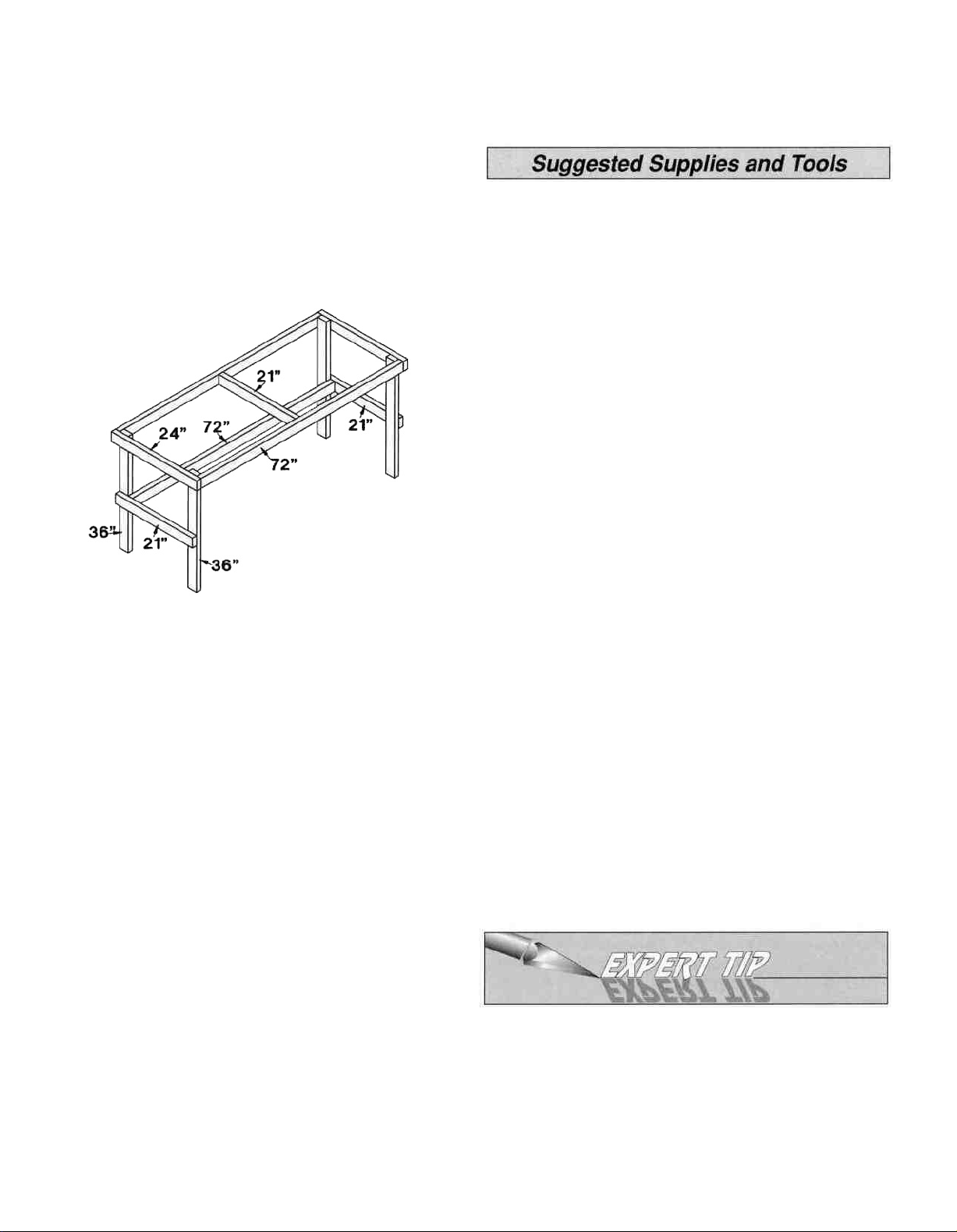
Here is a suggested approach for building an
inexpensive workbench. You will need (7) 6' two-by-fours of
good quality pine or fir, a 30" x 82" door, some 16d nails, a
hand saw and a hammer.
WORKBENCH FRAME
Assemble the workbench as follows:
1) Cut one 2x4 into three sections, two 24" long and one
21" long.
2) Nail the 24" pieces to the two ends of two straight 6'
pieces to make the frame for the top. Nail the 21" piece
in between the two 6' pieces across the center of the frame.
3) Cut two two-by-fours in half to make four 36" legs. Nail
(or bolt) the four legs to the frame with the 2" side facing
the long sides of the frame.
4) Cut two 21" side rails from one of the remaining boards.
Nail the two boards to the sides of each pair of legs.
5) Nail the last 6' board to the front side of the back legs,
level with the two side pieces. (1x3 Cross braces may
be nailed to the back legs for more rigidity.)
6) Center the door on the frame and either glue or use
double-sided, foam back sticky tape to hold it in position.
We recommended Great Planes Pro™ CA and Epoxy.
D 2 oz. CA adhesive-Thin (Great Planes GPMR6003)
D 2 oz. CA+ adhesive-Medium (Great Planes
GPMR6009)
D 1 oz. CA- adhesive-Thick (Great Planes
GPMR6014)
D 6-Minute Epoxy (Great Planes GPMR6045)
D 30-Minute Epoxy (Great Planes GPMR6047)
D Epoxy brushes (Great Planes GPMR8060)
D Epoxy mixing Sticks (Great Planes GPMR8055)
D CA Applicator tips (Hobbico HCAR3780)
D Hand or electric drill
D Drill Bits: 1/16", 5/64", 3/32", 1/8", 5/32", 3/16",
13/64", 1/4", 17/64", 5/16"
D Sealing iron (Top Flite)
D Heat gun (Top Flite)
D Hobby saw (X-acto® Razor Saw)
D Hobby knife, #11 Blades
D Pliers
D Wire cutters
D Screwdrivers (Phillips and flat blade)
D Round file (or similar)
D T-Pins
D String
D Straightedge with scale
D Masking tape (required for construction)
D Sandpaper (coarse, medium, fine grit)
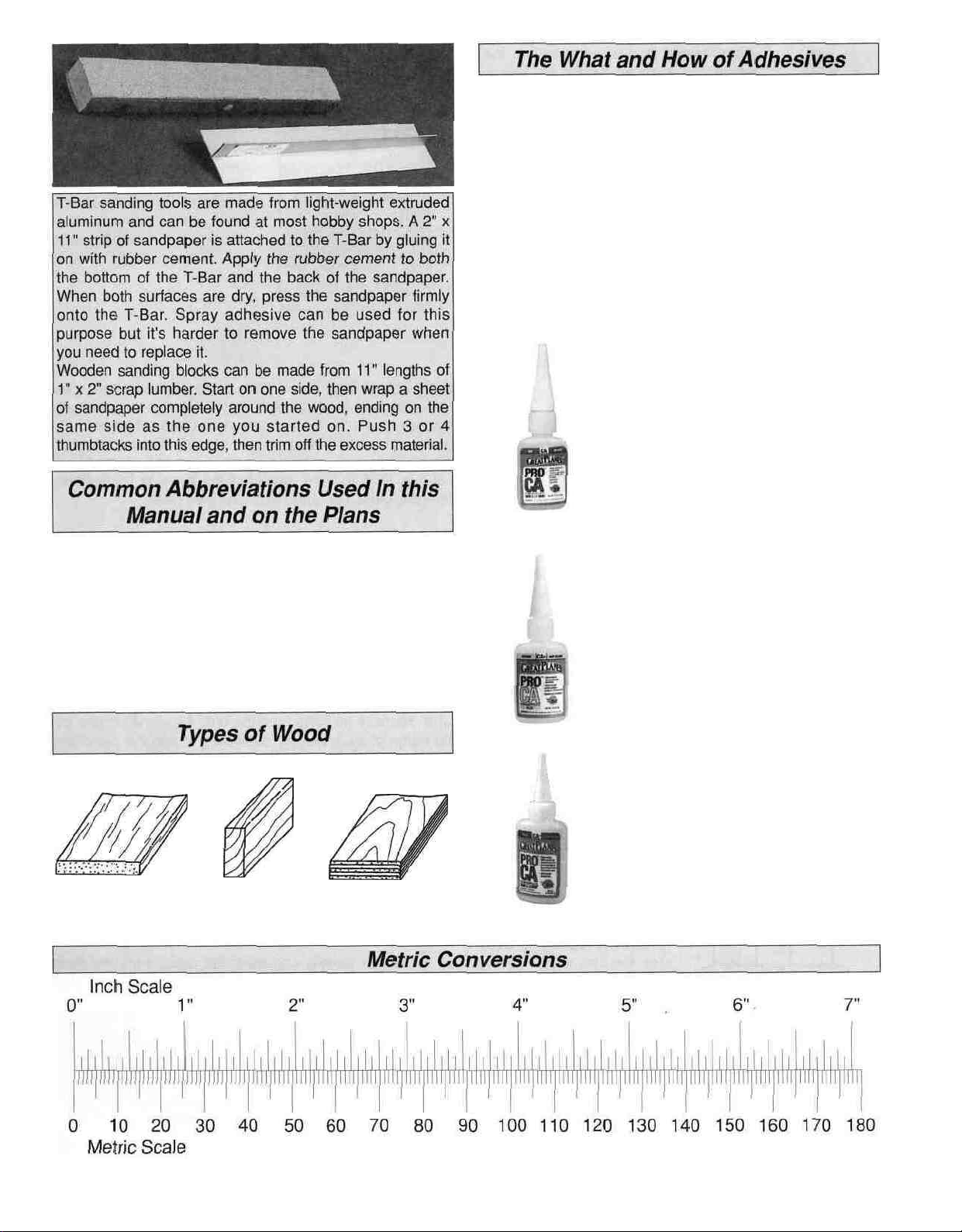
D T-Bar sanding block (or similar)
D Waxed paper
D Lightweight Balsa Filler such as Hobbico
HobbyLite'"
D IsopropyI rubbing alcohol (70%)
D Drafting triangle or carpenters square
D Dremel Moto-Tool® or similar (optional)
You will need to cover your work surface with
something you can push pins into. The back side of a 2' x 4'
sheet of ceiling tile makes a great building surface, or if you
want to cover a larger area you can buy a 4' x 8' sheet of
Celotex® insulation board from your local building
supply store.
Most of the tools listed below can probably be found
around the house. A few items like a razor saw, hobby
knife, sealing iron, heat gun, and glues can be purchased
from your local hobby dealer. As you get more involved with
On our workbench, we have four 11" T-Bar sanders,
equipped with #50, #80, #150 and #220-grit sandpaper.
This setup is all that is required for almost any sanding
task. Custom sanding blocks can be made from balsa for
sanding hard to reach spots. We also keep some
#320-grit wet-or-dry sandpaper handy for finish sanding
before covering.
4
Page 5
Cyanoacrylate or CA glue has changed the way models
are built more than any other advance in modeling
technology. In the good ol' days, model cement like
Ambroid, Duco, Comet, and Sigment were the glues of
choice. They all had a strong odor that could cause
dizziness, dried slowly (compared to CA) and became
brittle with age. CA, on the other hand, is stronger, works
almost instantly, and is bottled in three different viscosities
(thicknesses). CA is used for most glue joints, except where
epoxy is specified. CA does emit rather strong fumes (some
say it's like tear gas) as it cures, so rule number one is to
work in a well ventilated area. All CA glues work best if
the joints are smooth and fit well.
Thin CA is also known simply as CA.
This is the instant variety, used for most
initial assembly and tack gluing. Thin CA
is usually "wicked" into a tightly fitting
joint by putting a few drops on the seam,
then holding the parts together while the
CA penetrates and bonds the parts.
When gluing plywood or hardwood, a
mist of accelerator (see next page) will
help the CA work a little better.
Fuse = Fuselage
Stab = Horizontal stabilizer
Fin = Vertical fin
LE = Leading edge (front)
TE = Trailing edge (rear)
LG = Landing gear
Ply = Plywood
" = Inches
Balsa Basswood Plywood
CA+ is also known as medium or gap
filling CA. CA+ is used for surface
gluing, filling small gaps between poorly
matched parts, and for general purpose
applications. It cures slower than thin CA,
allowing you to apply a bead to two or
three parts before assembly. Curing time
without accelerator is 20-30 seconds.
CA- or thick CA is used when extra
positioning time is needed. CA- is a great
gap filler and is also used to make fillets
when a little extra strength is required.
Curing time is about 1-2 minutes.
5
Page 6
Accelerator is a liquid chemical that
comes in a spray bottle for use in
speeding up the cure time of all CA
types. It should be misted on, not
sprayed heavily on the joint. Accelerator
may cause exposed CA to bubble and
sometimes change color. A drawback to
accelerator is that the CA cures before it
has time to fully penetrate the wood, so
it should only be used sparingly-when
absolutely necessary.
30-minute epoxy is used for
extra strength (because it
can penetrate longer) and
where several parts must be
aligned and checked before it
cures. Working time is about
25 minutes, handling time
2 hours, and it's fully cured in
8 hours.
Great Planes Pro Wood Glue is an Aliphatic resin glue
that works well on all types of wood. It is non-toxic, virtually
odorless, and dries clear. Some people are sensitive to the
fumes and sanding dust caused by CA, so this is a good
alternative for general modeling use. Its only drawback is
that it is slow to cure, requiring the parts to be securely
clamped, pinned or taped while the glue dries.
Epoxy
Great Planes has two Epoxy formulations available for the
modeler. Both offer exceptional strength and convenient
working times. Use epoxy when the joint requires
exceptional strength, such as when installing the firewall,
when joining the wing panels, and when installing wing
hold-down blocks. As with most epoxies, you mix equal
parts of resin and hardener, stir well, then apply a thin film
to each part. Parts should be clamped, pinned, taped or
weighted in place until fully cured. Before the epoxy cures,
clean off any excess with a paper towel. A word of caution
about mixing epoxy-don't use extra hardener in the
hopes of making the mixture harder or work faster. Just
about all epoxies work best with exactly a 50/50 mix. When
you increase the amount of hardener you run the risk of
causing the cured epoxy to become either brittle or
rubbery-neither being as strong as a properly mixed batch.
6-Minute epoxy is used
for simple, small gluing
appl icatio ns-where
elaborate alignment is not
required. Working time
(before it's too gooey to
use) is about 5 minutes,
handling time 15 minutes
and it's fully cured in about
1 hour.
Okay, you've got your work space ready, your tools are at
hand, and you know how to choose and use the right glue
for the job. Let's get started!
D 1. Unroll the plan sheets. Reroll the plans inside out to
make them lie flat.
D 2. Remove all parts from the box. As you do, figure out
the name of each part by comparing it with the plans and
the parts list included with this kit. Using a felt tip or ball
point pen, lightly write the part name or size on each piece
to avoid confusion later. Use the die-cut patterns shown on
pages 7 and 8 to identify the die-cut parts and mark them
before removing them from the sheet. Save all scraps. If
any of the die-cut parts are difficult to punch out, do not
force them! Instead, cut around the parts with a hobby
knife. After punching out the die-cut parts, use your T-Bar
or sanding block to lightly sand the edges to remove any
die-cutting irregularities.
D 3. As you identify and mark the parts, separate them
into groups, such as fuse (fuselage), wing, fin, stab
(stabilizer) and hardware.
Zipper-top food storage bags are handy to store your
parts as you sort, identify and separate them into
sub-assemblies.
6
Page 7
DIE-CUT PATTERNS
7
Page 8
DIE-CUT PATTERNS
8
Page 9
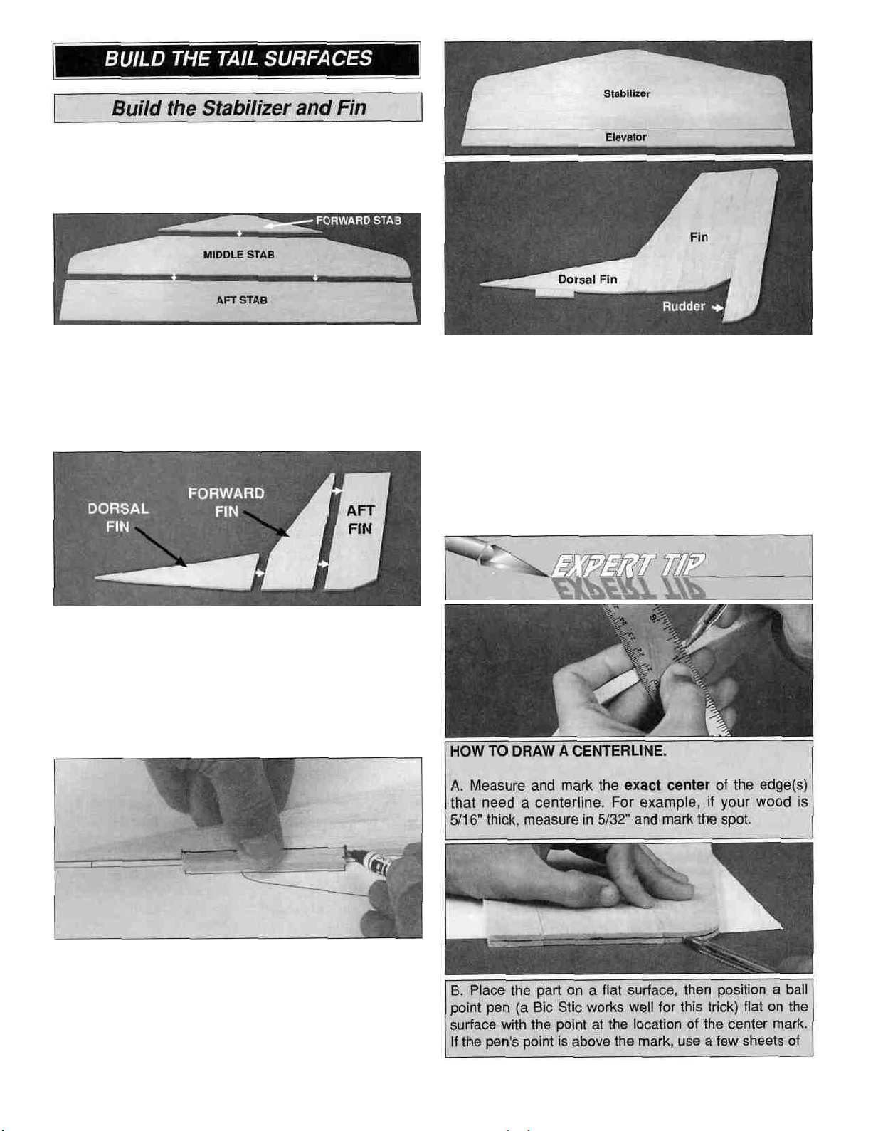
Work on a flat surface over the plans covered with waxed
paper. Refer to the plans to identify the parts and
their locations.
D 1. Locate the shaped 5/16" balsa forward, middle and
aft stab parts. Check their fit and sand the mating edges as
needed. Glue the three parts together by applying a light
bead of medium CA to the edges, then press the parts
together. Wipe off any excess from the surface before
it cures.
D 5. Temporarily join the 5/16" x 1-1/4" x 27" balsa
elevator to the stab and the 5/16" shaped rudder to the fin
with masking tape. Draw a centerline (see Expert Tip
below) around the outside edges of both assemblies. Use a
sanding block loaded with 150-grit sandpaper to round the
perimeter edges of both assemblies to match the plans. Do
not roundoff the bottom edge of the fin. Refer to the plans
for the exact shape. The centerline will help you to keep the
shape symmetrical.
D 2. Locate the shaped 5/16" balsa dorsal, forward and
aft fin parts. Check their fit and sand the mating edges as
needed. Work over the plans (don't forget the waxed
paper), then glue the three parts together with a thin bead
of medium CA. Wipe off any excess from the surface
before it cures.
D 3. Position the 5/16" x 5/16" x 3" balsa dorsal fin tab
stick over the plans under the dorsal fin, then mark its
location on the bottom edge of the dorsal fin. Glue the tab
to the dorsal fin with medium CA.
D 4. Sand the seams of the stab and fin smooth with
sharp, 220-grit sandpaper and a sanding block.
9
Page 10
paper under the part to raise the mark to the same level
as the pen's point. If the pen is too low, raise it with
paper shims (or playing cards) to the right height.
C. Now, depending on which is shimmed (the part or the
pen), rotate the un-shimmed component around the
perimeter to draw the line.
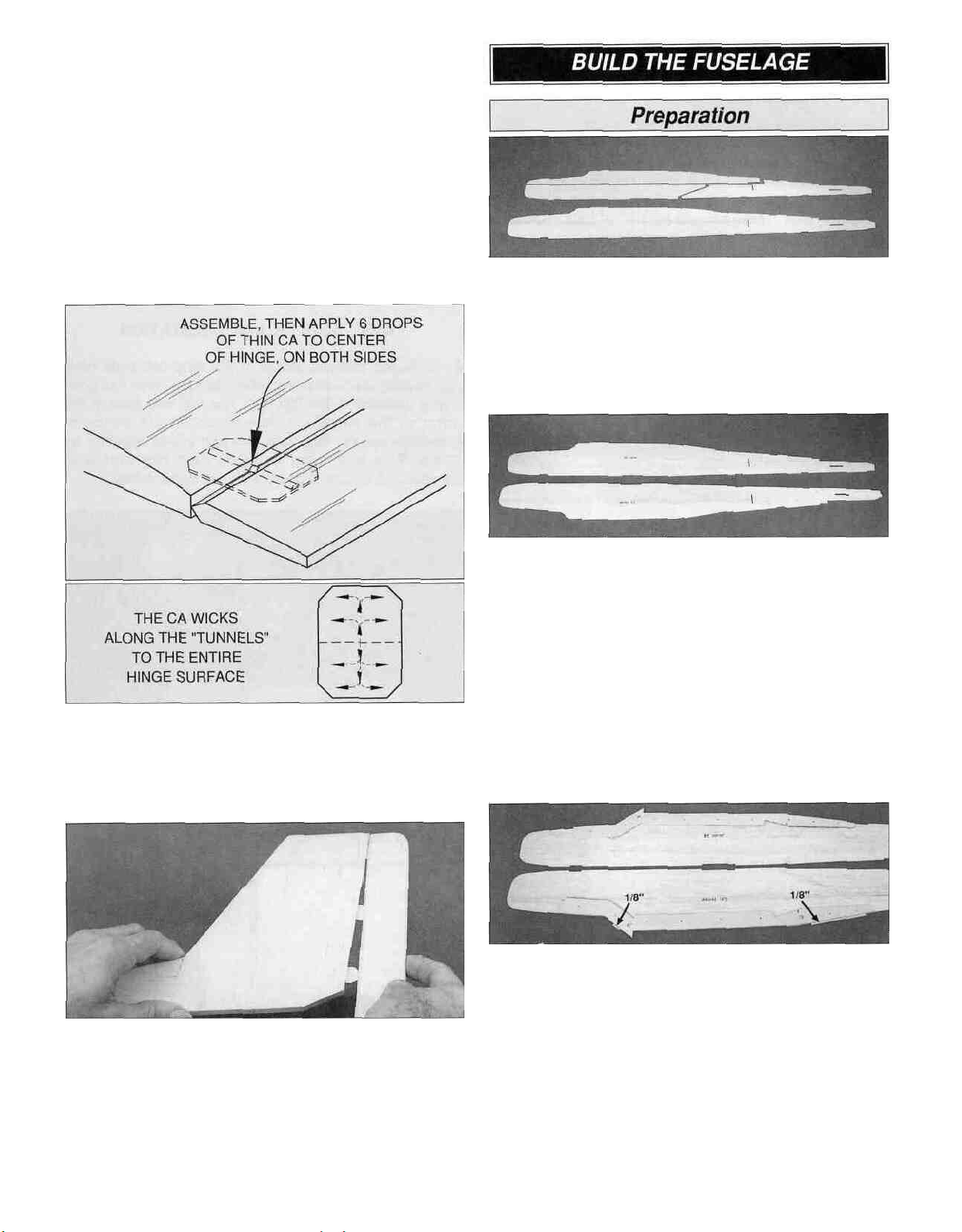
the flow of CA to the back of the hinges. This results in
hinges that are only "tack glued" approximately 1/8" to
1/4" into the hinge slots. The following technique has been
developed to help ensure thorough and secure gluing.
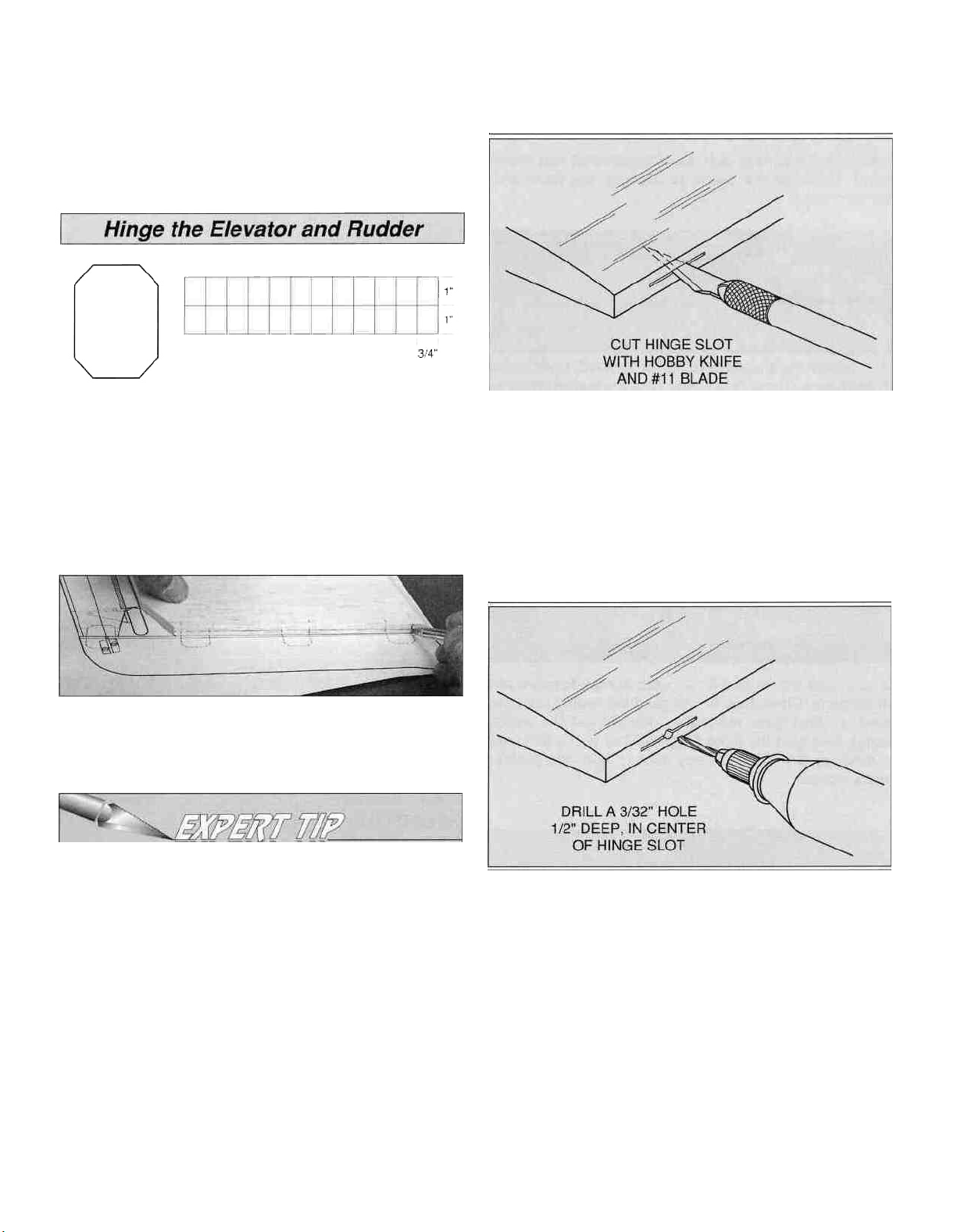
D 6. With reference to the above sketch, cut 18 hinges
from the supplied 2" x 9" composite hinge material and cut
the corners as shown. You will need five hinges for the
elevator and four for the rudder. Store the remaining hinges
for use later during construction.
D 7. Separate the elevator and rudder from the stab and
fin. Draw a centerline on the TE of the stab and the LE of
the elevator. Do the same for the fin and rudder.
D 8. Use the plans as a guide to mark the locations of the
hinges on all tail components-fin, rudder, stab, and
elevator. Refer to the Expert Tip that follows, then cut
matching hinge slits in all four parts.
A. Cut the hinge slot using a #11 blade in a standard #1
knife handle. Begin by carefully cutting a very shallow
slit at the hinge location. This first cut is to establish your
cut in the right place, so concentrate on staying on the
centerline and don't cut too deep! Make three of four
more cuts in the same line, going slightly deeper each
time. As you make these additional cuts, work on going
straight into the wood. Continue this process while
"wiggling" the knife handle forward and backward until
the blade has reached the proper depth for the hinge.
The hinge material supplied in this kit consists of a
3-layer lamination of mylar and polyester. It is specially
made for the purpose of hinging model airplane control
surfaces. Properly installed, this type of hinge provides
the best combination of strength, durability and ease of
installation. We trust even our best show models to
these hinges, but it is essential to install them
correctly. Please read the following instructions and
follow them carefully to obtain the best results. These
instructions may be used to effectively install any of the
various brands of CA hinges.
The most common mistake made by modelers when
installing this type of hinge is not applying a sufficient
amount of glue to fully secure the hinge over its entire
surface area; or, the hinge slots are very tight, restricting
B. Drill a 3/32" hole, 1/2" deep, in the center of the
hinge slot. If you use a Dremel Moto-Tool® for this task, it
will result in a cleaner hole than if you use a slower speed
power or hand drill. Drilling the hole will twist some of the
wood fibers into the slot, making it difficult to insert the
hinge, so you should reinsert the knife blade, working it
back and forth a few times to clean out the slot.
C. Trial fit the hinges into the slots and temporarily
attach the control surface, to verify the fit and operation.
IMPORTANT: DO NOT GLUE THE HINGES IN PLACE
UNTIL THE MODEL IS COVERED! YOU WILL BE
INSTRUCTED WHEN TO GLUE THE HINGES.
10
Page 11
D. Insert the hinges and install the control surface.
Verify the left-right positioning of the control surface, and
close up the hinge gap to 1/32" or less. It is best to leave
a very slight hinge gap, rather than closing it up tight, to
help prevent the CA from wicking along the hinge line.
Make sure the control surface will deflect to the
recommended throws without binding. If you have cut
your hinge slots too deep, the hinges may slide in too
far, leaving only a small portion of the hinge in the
control surface. To avoid this, you may insert a small
pin through the center of each hinge, before installing.
This pin will keep the hinge centered while installing the
control surface. Remove the pins before proceeding.
D 1. Lightly sand the edges of the three die-cut 1/8" balsa
fuse side pieces. Test fit the upper, lower and aft sections
as shown in the photo. When satisfied with the tit, make a
fuse side using thin CA to glue the three parts together over
waxed paper covered plans. Make a second fuse side in the
same manner. Use fresh, 220-grit sandpaper on a sanding
block to go over all joints to make sure they are smooth.
D 9. Sand the LE of the elevator and rudder to a "V"
shape as shown on the plans, but leave the TE of the stab
and fin squared off.
D 10. Test fit the elevator and rudder.
Congratulations! You made it through the first stage and
should be proud of yourself. You should also have learned
a few "tricks of the trade" as used by the guys that
designed this kit. Remember, all us modelers are just
"plane folks" and we like to help where we can...
D 2. Examine the two fuse sides for blemishes, then
position them on your workbench exactly as shown in the
photo, with the "bad" sides facing up if possible. You need to
build a right and a left side so be sure that the sides are
mirrored as you look at them. Mark the inside surfaces with
"right" and "left."
D 3. Lightly sand the edges of the die-cut 1/8" ply upper
and lower fuse doublers (See the Die-Cut patterns on
page 7.) Drill a 1/16" hole at each of the punch marks on all
the fuse doubler parts. These holes allow CA to wick into
the center portions of the doublers when you glue them to
the fuse sides.
D 4. Align the top edge of the top doubler with the top of
the fuse side at the wing saddle. Slide it back and forth
until the front edge of the windshield and rear end are
aligned as shown in the photo. The balsa side behind the
wing saddle protrudes above the doubler by 1/8". Take
your time as this is a crucial step in building a straight fuse.
When the doubler is positioned, wick thin CA between the
doubler and the fuse side, around all edges and also
through the holes you drilled. While holding the doubler in
position, wipe away any excess CA with a tissue or paper
towel before it cures.
11
Page 12
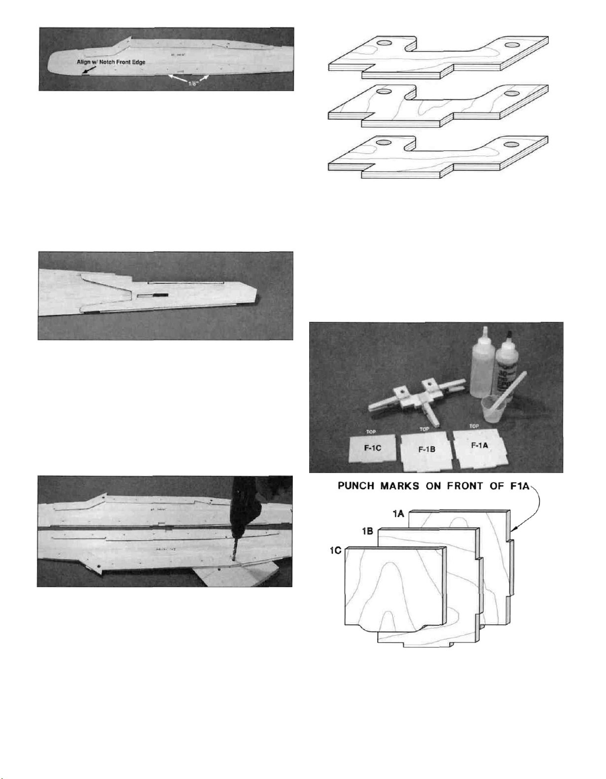
D 5. Align the lower doubler as shown, with the front
edge even with the front edge of the bottom notch and the
landing gear block notch flush with the "indented" location
on the fuse side. There should be 1/8" of balsa showing
below the doubler when it's properly aligned. Glue the
lower doubler in position with thin CA the same way as the
upper doubler.
D 6. Repeat steps 4 and 5 to glue the doublers to the
second fuse side. Be sure to build a right and a left side.
(See the photo at Step 8.)
D 7. Align the die-cut 1/8" balsa aft fuse doubler even with
the rear end of the fuse. Position the doubler so that 1/8" of
the side sheet protrudes along the bottom edge and also
at the location of the stab as shown, then glue it in position
with thin CA. The pushrod exit slots are intentionally
staggered to allow the pushrods to angle smoothly through
the fuse. Repeat for the other side.
WING BOLT PLATE LAMINATION
D 10. Notice that two pieces of the wing bolt plate have
grain running in one direction while the third piece has grain
running opposite to the first two. The odd one goes in the
center of the sandwich. Mix up about 1/4 ounce of
30-minute epoxy, then glue the bolt plates together as
shown. This assembly must be held together with
clothespins or weighted down while the epoxy cures.
Skip step #8 if you will be using bolts to mount
your wing.
LI 8. If you will be installing the dowels for rubber band
wing attachment, you need to drill 5/16" holes through the
fuse sides at each die-cut location in the upper doublers.
Use a backup block of scrap wood under the fuse side to
prevent splitting the balsa as the drill bit goes through.
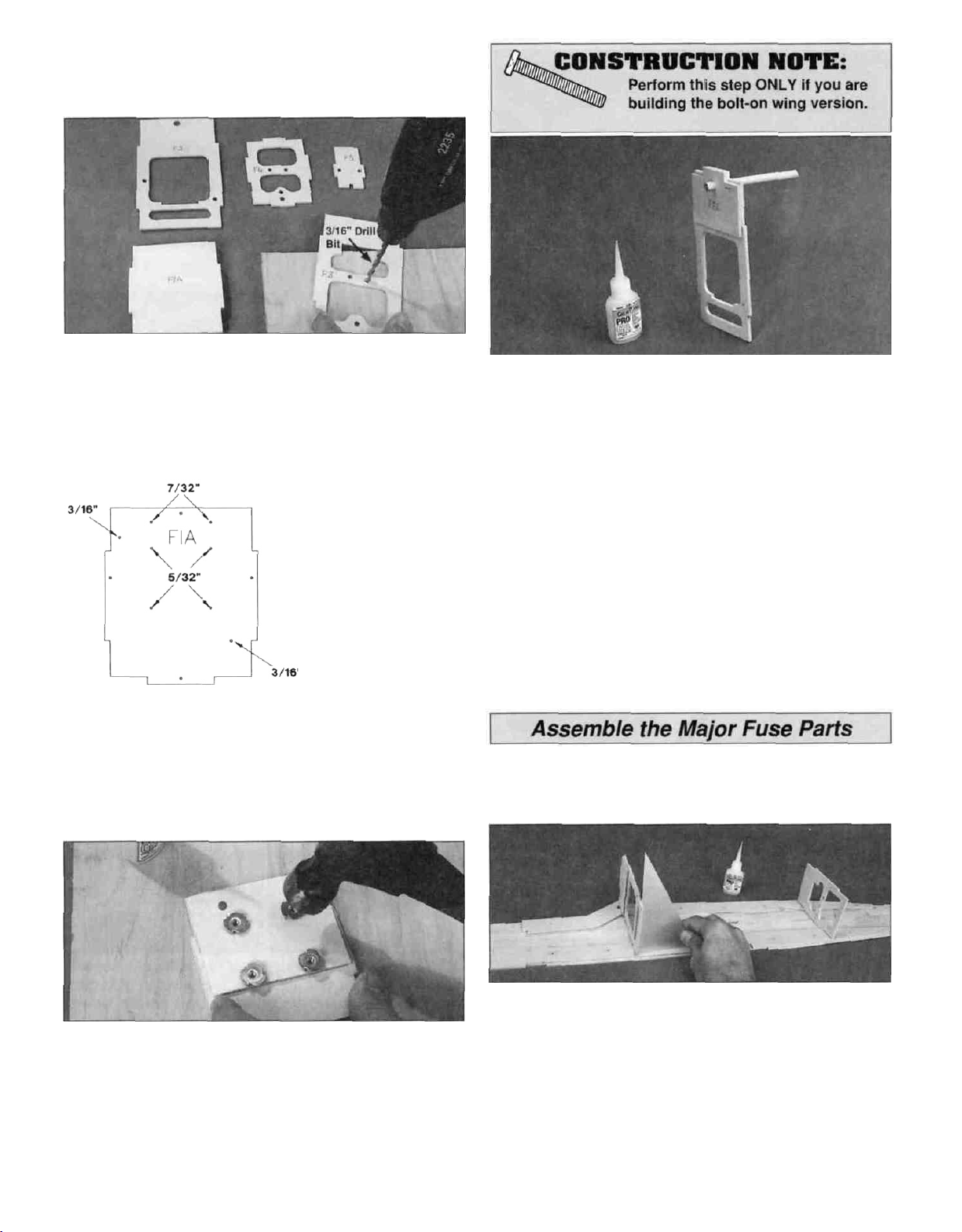
D 9. Locate the three die-cut 1/8" ply firewall parts F-1A,
F-1B and F-1C and the three die-cut 1/8" ply wing
bolt plates.
Note: you need the wing bolt plates for strength even if you
will be using rubber bands to attach the wing.
FIREWALL LAMINATIONS
(VIEWED FROM THE REAR)
D 11. Use the remaining 30-minute epoxy to glue F-1A,
F-1B and F-1C together. Be sure that F-1A (the one with
the punch marks) is on top of the stack with the punch
marks facing outward, that the locking tabs are aligned and
12
Page 13
that F-1C is flush with the top edge of the assembly (see
sketch) This assembly must be held together with
clothespins or weighted down while the epoxy cures
D 12 Now you need to get out your drill and a 3/16" drill bit
to prepare the formers for pushrods Position each former
over a piece of scrap wood, then drill a 3/16" hole through
each of the punch marks in the die-cut 1/8" ply formers F-2
through F-5. Do not drill the F-1 assembly during this step
D 15 Insert a 5/16" wing dowel through the hole at the
top of F-2 Slide the die-cut 1/8" ply former F-2A onto the
dowel from the front of F-2 (that's the side with the
punched number) to check the fit Glue F-2A in position
with medium CA but don't glue the dowel to the formers
as it's only being used for alignment Carefully remove
the dowel before the CA cures
The top and bottom
3/16" holes are for the
standard 2-stroke
engine installation
These may have to
switch sides if using a
4-stroke engine (See
sketch at Step 2 on
page 34)
FIREWALL HOLE SIZES
D 13 Refer to the sketch, then drill 3/16" pushrod tube
holes through the firewall where indicated Change your bit
size to 7/32" (or better, 15/64") and drill the two fuel tube
holes through the top of the firewall Finally drill four 5/32"
holes in the firewall for the engine mount blind nuts
D 16 Examine your work Clean up any "fuzz" from
around the holes you drilled and also the edges of the
formers with a sanding block and 220-grit sandpaper
IMPORTANT: Position all of the formers with the embossed
numbers facing the front of the model
D 14 Insert a 6-32 blind nut into one of the holes in the
back of the firewall (F-1C) then tap it gently with a hammer
to start it into the hole Now you can either squeeze the
blind nut all the way into the firewall with a vise or finish
seating it with your hammer Put a drop of thin CA on the
outer edge of the flange to secure the blind nut in position
Repeat this operation for the other three blind nuts.
D 1 Test fit the die-cut 1/8" ply F-2 and F-3 formers in
position on the right fuse side When you test fit the
formers, be sure they line up with the bottom edge of the
lower doubler If you will be bolting on your wing the F-2A
former must face toward the front of the model If you will
not be bolting on your wing, former F-2A is not needed
Glue both parts to the fuse side as shown with medium CA
Hold the parts vertical with a triangle or carpenter's square
while the CA cures
13
Page 14
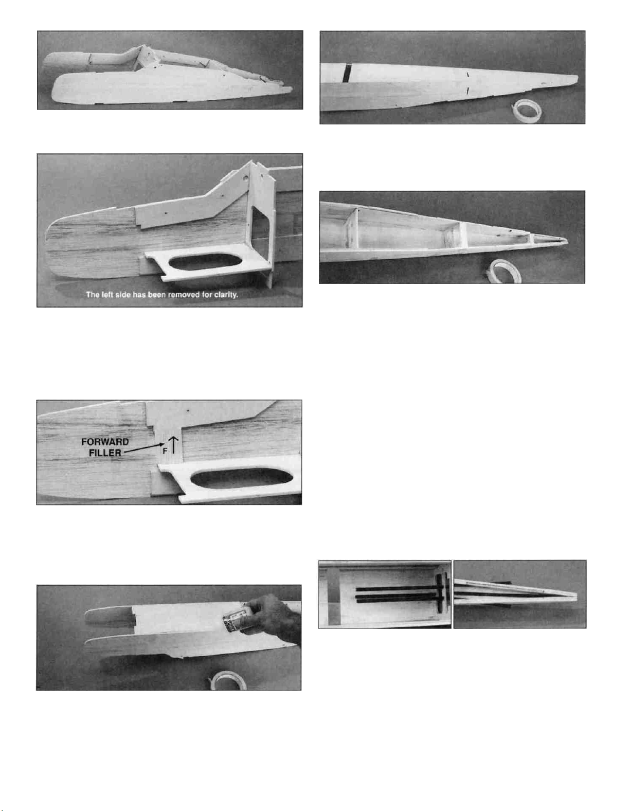
D 2. Glue the left fuse side to formers F-2 and F-3.
D 3. Insert the die-cut 1/8" ply tank floor between the fuse
sides. The tab at the rear end should fit into the notch at the
bottom of F-2 and the bottom of the tank floor should fit on
top of the lower fuse doublers. Squeeze the fuse sides to
the tank floor, then glue the tank floor in position with
medium CA.
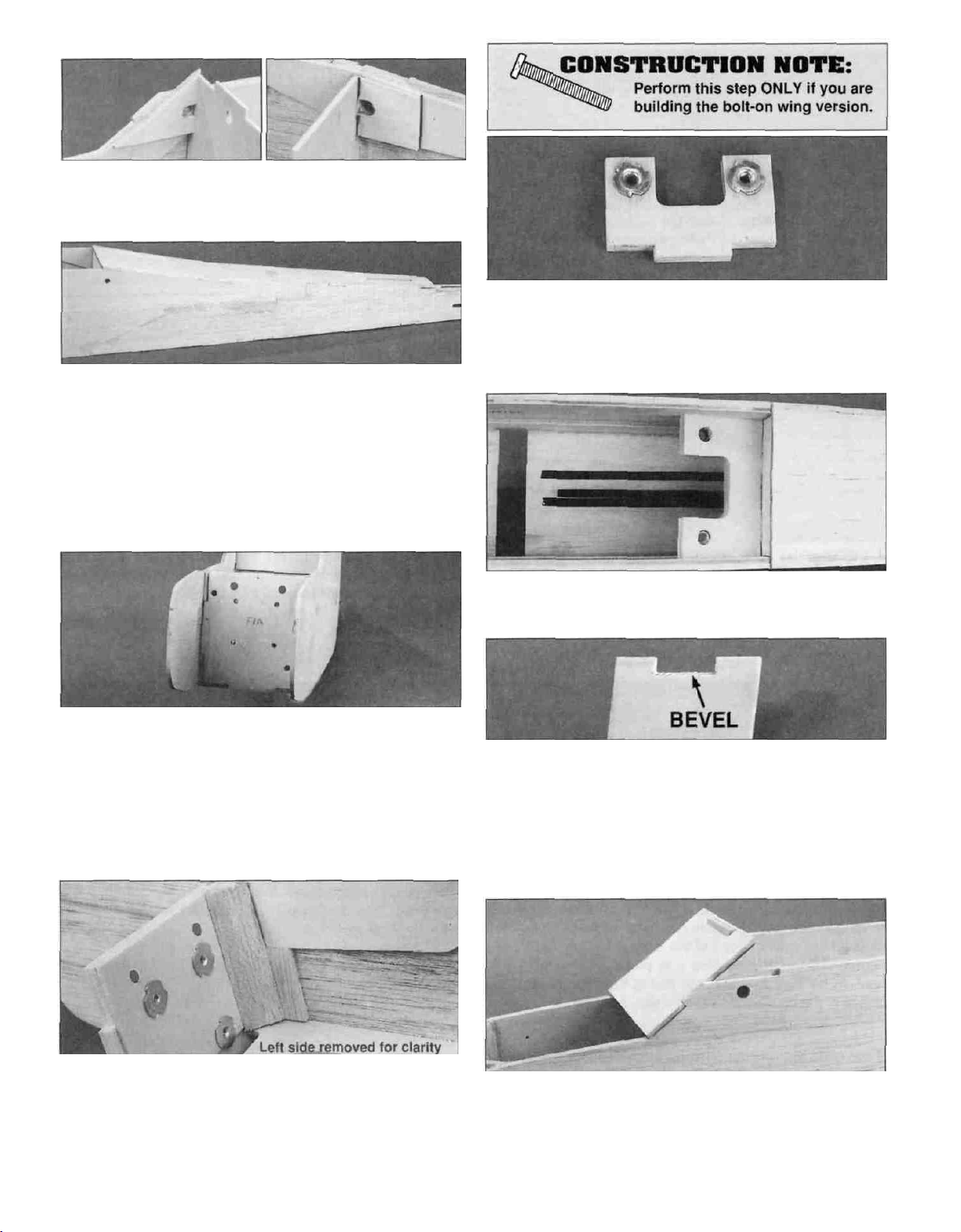
D 6. Test fit the die-cut 1/8" balsa aft fuse bottom
between the fuse sides. Temporarily hold the bottom in
position with a few strips of masking tape-do not glue yet!
D 7. Install the die-cut 1/8" ply formers F-4 and F-5 in the
notches of the fuse sides and bottom. Be sure that the
antenna tube hole is toward the bottom of the fuse. Use
more masking tape to hold the formers tightly in position.
When you are satisfied that everything looks square and
true, place the fuse on a length (at least 36") of waxed
paper, then wick thin CA into the joints (from the inside)
between the fuse sides, bottom, and the formers. Press
down on the framework as you do the gluing to hold the
frame square.
D 4. Fit the two die-cut 1/8" balsa forward fillers between
the tank floor and top doublers. The front edge of the filler
must be flush with the front edge of the tank floor and the
back edge of the doubler notch.
D 5. Test fit the die-cut 1/8" balsa front fuse bottom into
the notches and recess on the bottom of the fuse. When
satisfied with the fit, wick thin CA along both outside edges.
Turn the fuse over, then wick thin CA into the inside joints
between the bottom and the formers. Follow with medium
or thick CA in any open joints.
D 8. Apply medium CA along all inside joints to
permanently secure the framework.
D 9. Cut one of the 36" plastic outer pushrod tubes to
32". This will be used for your antenna tube. Cut two more
pushrod tubes to 30". These will be used to contain the
elevator and rudder pushrods.
D 10. Lightly sand the outside of the pushrod tubes with
150-grit sandpaper to make them "receptive" to glue. Slide
the 32" antenna tube through the bottom hole in formers
F-3,F-4 and F-5 all the way to the tail. Slide the other two
pushrod tubes through the upper holes in the same
formers and out through the exit slots at the rear of the
fuse. These tubes should protrude about 1/2" past the
rear end of the slots.
D 11. Use medium CA to glue the pushrod tubes to each
former and the inside of the exit slots.
14
Page 15
Skip step 12 if you will be using wing bolts!
D 12. Glue the die-cut 1/8" ply front and rear dowel
triplers in position with medium CA as shown in the photos
and on the plans.
D 13. The die-cut 1/8" balsa fuse top has a partially diecut score across the width at the wide end. If necessary
deepen the score with a hobby knife. With the score facing
up, align the score with the edge of your work table and
then gently "crack" the wood along the line. Do not break
the part in two. Turn the fuse top over so that the score is
facing down, then test fit the fuse top. Wick thin CA into the
joint between the top, former tabs and the sides. Follow
with medium CA to fill in any gaps.
16. If you will be using bolts to attach your wing, install
two 1/4"-20 blind nuts in the laminated wing bolt
plate. Use a hammer or vise and thin CA like you did
when installing the blind nuts in the firewall.
D 14. Test fit the firewall assembly in the front end of the
fuse. Clean up the edges with a sanding block and 150-grit
sandpaper if required. Use 6-minute epoxy to glue the
firewall assembly into the notches at the front of the fuse
doublers and to the front edge of the fuel tank floor. Be sure
that the bottom lock tab points toward the bottom of the
fuse. Use masking tape or #64 rubber bands to hold the
fuse sides together until the epoxy has cured.
D 17. Use 6-minute epoxy to glue the wing bolt plate into
the notches of the ply doublers and F-3.
D 18. Carefully sand or cut a bevel along the bottom edge
of the notch at the top of the die-cut 1/8" ply windshield.
This bevel will allow the windshield to fit flush against F-2. If
you will be bolting on your wing, F-2A has already been
glued to F-2. In this case you will need to increase the
depth of the notch by 1/8" to allow for the additional former
thickness. Create the bevel after you enlarge the notch.
D 15. Cut two firewall reinforcements from the 1/2" x 20"
triangular balsa stick. The triangular stock fits behind the
firewall, on top of the fuel tank floor. Use 6-minute epoxy
to glue one piece in each corner. Sand the top end flush
with the top of the fuse.
D 19. When the windshield fit looks good, glue it in
position with medium CA. Sand the top portion of F-2 (A)
flush with the front surface of the windshield. Sand the rear
windshield overhang flush with the back of F-2.
15
Page 16

D 20. Edge glue the two die-cut 1/4" upper and lower
nose blocks together. Sand the outside edges lightly to
clean them up. Test fit the nose blocks in the engine
compartment to make sure that the top rear notches line
up. Sand the rear edge of the blocks until a good fit
is obtained.
D 21. Glue the nose blocks to the inside surfaces of the
engine compartment and the front of F-1A with 6-minute
epoxy. Sand the outside edges flush with the fuse sides.
D 24. Glue the two die-cut 1/8" balsa cabin top fillers in
the notches on both sides of the windshield.
D 25. Test fit the die-cut 1/8" ply stab base (SB) into the
recess at the rear end of the fuse. It should fit flush with the
top edge of the fuse sides. Glue the stab base in position
with medium CA when satisfied with the fit.
If you will be using wing bolts, skip this step.
D 26. Test fit the two 5/16" x 6" dowels through their holes
in the fuse then remove them until the model is covered.
It's usually easier to insert the dowels if the ends are
slightly chamfered or rounded off. After the model has
been covered you will reinstall the dowels using epoxy.
D 22. Locate the die-cut 1/8" ply hatch retainer (HR).
Hopefully you didn't throw away this part as it came from the
center of former F-2. Draw a line 3/8" from the edge with
the rounded corners. Position the hatch retainer so that the
line is on the straight edge of the die-cut 1/8" ply hatch and
is centered. Before you glue it in place with medium CA,
check to be sure that you are gluing it to the un-punched
surface of the hatch-the next step explains why.
D 23. Slide the retainer (HR) under the bottom edge of the
windshield and seat the hatch in the nose block notches.
Tape the hatch in position or hold it firmly while you drill
1/16" holes through the hatch into the firewall at the three
punch marks. Remove the hatch, then enlarge the holes in
only the hatch with a 3/32" drill bit.
D 1. Test fit the 1/2" x 3/4" x 3-1/2" grooved hardwood
landing gear (LG) rail in the slot on the bottom of the fuse.
It should fit snugly between the ends of the balsa bottom
sheeting and the notches in the fuse sides. Remove the
landing gear rail, then use 6-minute epoxy around all points
of contact to glue it in position.
D 2. Use medium CA to glue the two die-cut 1/8" ply
landing gear doublers (LGD) to the inside of the fuse to
make a bridge across the LG rail.
16
Page 17

D 3 Use 30 minute epoxy to glue the 3/4" x 3/4" x 1/2"
hardwood landing gear blocks to the fuse sides and LG
rail in the recesses created by the landing gear doublers A
scrap balsa stick should be wedged between the blocks to
hold them in position while the epoxy cures
Note: You may work on the next section (engine & fuel
tank) while waiting for the epoxy to fully cure
D 4 After allowing the LG assembly to cure for a few
hours (overnight is best) fit the die cut 1/8 ply landing
gear drill guide into the groove in the rail flush with the
fuse sides as shown Drill a 3/32" pilot hole through the
rails and underlying blocks at each of the punch marks on
the guide Use care to make the holes as perpendicular to
the fuse bottom as possible Check the inside of the fuse to
make sure that the holes are straight and clearly in the
hardwood LG blocks then redrill the holes with a 3/16" bit,
making angular adjustments if necessary
The Great Planes adjustable engine mount is simple and
convenient to use It may be used to mount most 40 60
two stroke and 40 70 four stroke engines Nose gear
bearings are incorporated in the mount Because the nose
gear bearing holes are prednlled for 5/32" wire, you will
need to enlarge the holes by drilling them out with a 3/16"
or 13/64" bit If you have a numbered drill bit set the #11 bit
is perfect If you use a 3/16" bit wiggle the bit around to
create a slightly loose fit or the nose gear wire will be tight
Caution: Don't overdo the enlargement process!
D 1 Cut or break the spreader bar from each mount half
Carefully trim any extra material left by the spreader bar
from each mount half as the surface where the spreader
bars were attached must be smooth to allow the mount
halves to fit together Trim the flashing from any rough
edges if necessary Assemble the mount halves as shown
D 2 Temporarily install the engine mount on the firewall
using four #6 flat washers and four 6-32 x 1" machine
screws Don't tighten the screws completely until after the
engine has been positioned
D 3 Remove the needle valve from the engine, then position
the engine on the engine mount Slide the engine mount
halves apart until the engine mounting lugs will sit flat on the
rails Adjust the mount until the firewall centerline is centered
between the "tick" marks on the mount Tighten the 6-32
screws to hold the mount firmly in position against the firewall
D 5 Test fit the main landing gear. You need to carve a
small radius in the LG rail holes toward the center of the
fuse to allow the LG wire to fully seat in the holes Also, it is
helpful to file off the sharp edges at the ends of the LG
wire After fitting the LG in position, the LG may be
removed and set aside until final assembly.
NOTE: If you will be installing a 4 stroke engine you
need to plan ahead for servo location and pushrod
routing Refer to the sketch on page 34 and the fuselage
plans for the 2 stroke/4 stroke servo and pushrod setup
D 4 Position the engine so that the backplate of a spinner will
be 4-7/8" (124mm) in front of the firewall Carefully mark the
engine mounting holes on the rails with a sharpened piece
of wire or a pencil lead NOTE: If installing an 0S 70 4
stroke engine the engine will have to be slightly forward of the
recommended position to allow for the choke mechanism This
will not cause a balance problem and is quite acceptable
17
Page 18

D 5. Remove the engine and engine mount from the fuse.
Use a centerpunch or sharpened nail to "dimple" the marks
on the rails, then drill a 7/64" hole through the rails at each
punch mark. If you have access to a drill press, this is the
best tool for the job. However, if you are using a hand-held
electric drill, try to keep the bit perpendicular to the rails.
D 6. Reinstall the engine mount and position the engine
over the holes in the rails. Mark the location of the needle
valve on the inside of the nose blocks. Use a hobby knife
and round file to shape the needle valve access in the fuse
side (See next photo.) Redrill the throttle and steering
pushrod holes with a 3/16" bit to puncture the tri-stock.
D 7. Install the engine with four #6-32 x 3/4" sheet metal
screws that have been provided with this kit.
through the throttle pushrod tube into the radio
compartment. You will need to make a couple of bends in
the pushrod so that the clevis will engage the throttle arm
on the engine without binding. Install a silicone retainer
around the clevis when satisfied with how the wire is bent,
then "snap" the clevis onto the throttle arm.
D 11. Assemble the fuel tank following the manufacturer's
instructions*. Push a 6" length of fuel tubing onto the tank's
vent and fuel supply nipples. Install the fuel tank in the fuse
with the vent tube passing through the firewall on the right
and the fuel supply tube on the left (as viewed from the
back of the firewall). Check for kinks and fix any problems
before proceeding.
D 8. Cut two 12" long pieces of outer pushrod tube from
the remaining 36" tube, then roughen the outside surface
with 150-grit sandpaper. Insert the pushrod tubes through
the throttle and nose wheel steering pushrod holes in the
firewall and F-2, leaving about 1/16" of both tubes
protruding past the firewall. Glue the pushrod tubes
in place.
D 9. Cut a 36" threaded wire pushrod in half to make
two 18" pieces. The wire with threads on one end is for the
throttle and the plain piece is for the nose wheel steering
pushrod. Save the steering pushrod for later use.
*Note: We used a 12 oz Great Planes tank (GPMQ4105) in
our prototypes. By using the supplied right-angle fuel
supply tube, the fuel can be routed to the top of the firewall
without the risk of kinking the tube.
D 12. Cut some strips of 1/4" latex foam rubber to pack
under and around the tank (see photo for step 11). The
foam rubber holds the tank in place and helps prevent fuel
"foaming" caused by engine vibration.
D 13. Hold the muffler in position and, if it touches the top
of the nose block, mark the area that will need trimming.
Remove the engine, then cut the muffler clearance with a
razor saw and hobby knife. Shape the bottom corners with
a round file for a neat appearance. Attach the muffler to the
engine before testing the fit. There should be a gap of
3/32"-1/8" around the muffler header.
...................Nylon Clevis (1)
D 10. Screw a nylon clevis 14 revolutions onto the 18"
length of threaded pushrod wire. Insert the pushrod
Well, we're making progress. The fuse assembly is about
99% finished, the stab and fin are done, the engine and
tank are nicely installed. Have a soda. clean up your
workbench, then let's start putting the pieces together.
18
Page 19

Preparation
D 1 Measure the total width of the stab (approximately
25") and make a mark at the exact midpoint of the TE. Use
a drafting triangle or a carpenter's square to draw an
accurate centerline on the top of the stab, starting at the
mark on the TE and extending to the LE.
D 2 Accurately measure the width of the fuse at the top of
F-3 and just in front of the stab base Mark the exact center
of the fuse top at both of those locations Lightly draw a
centerline between these two marks Stick a pin into the
fuse top at the F-3 centerline mark.
D 5 Now check the stab alignment by measuring from the
pin at F-3 to the stab TE at both tips Adjust the alignment
of the stab (while keeping the stab centered on the fuse)
until these measurements are equal Once you have the
stab pinned in correct alignment, make a couple of
reference marks on the stab and the fuse, so you can
quickly realign the stab during the gluing operation.
Now proceed to align and attach the stab and fin as
follows:
D 3 Lay the stab in place on the stab base and center it
as well as you can using the marks you made above Pin it
in place Lay a 36" straightedge (yardstick) on edge, across
the front of the wing saddle on top of the fuse, as shown in
the photo. Hold the straightedge in place by clipping a
couple of clothespins to the fuse sides behind the
straightedge
D 4. Check the alignment of the stab by standing 6 to 10
feet behind the airplane and crouch down until the stab TE
and the bottom of the straightedge are very close together
If the stab TE is not exactly parallel with the straightedge,
remove the stab and sand the stab base carefully with a
sanding block, then replace the stab and recheck its
alignment Note that you do not have to sand much to
make a big change in the stab angle Keep doing this until
the stab lines up very closely with the straightedge
D 6 Remove the stab from the fuse Mix up a batch of
30-minute epoxy and apply it to the stab base Lay the stab
in place and pin it back in correct alignment using your
reference marks Carefully remove any excess epoxy that
squeezes out of the Joint under the stab Recheck the stab
alignment carefully before the epoxy cures.
D 7 Position the fin on the fuse top and stab with the
bottom of the "angled" rear edge even with the TE of the
stab, then pin it in place Check its alignment with the
centerline of the fuse with a long straightedge held against
the side of the fin The straightedge must be parallel to the
fuse top centerline Use thick CA to glue the fin in position
while holding a triangle against it and the stab to maintain
vertical alignment
19
Page 20

D 8. Locate the remaining piece of 1/2" balsa tri-stock and
cut two 7" pieces from it These will be used to reinforce the
fin Hold the 1/2" dimension of both pieces together (backto-back), then shape both parts simultaneously as shown in
the photo and on the plans
D 9 Use thick CA to glue the shaped fin reinforcements
to the stab and fin Sand the front half of the fin
reinforcement to blend with the fuse top Also, add
lightweight balsa filler to blend the stab to the fuse top.
Building the wing for the PT-60 is pure fun Even if this is
your first kit you won t have any trouble building a beautiful
wing that is true The secret is not to use any glue until
instructed to do so. You will soon see that the structure
just about holds itself together without any help, giving you
the opportunity to make sure that everything fits perfectly
before making an 'irreversible oops
1
We mentioned at the front of this manual that you have a
choice in the type of wing to build — trainer or sport If this
is your first R/C model, we strongly (read that STRONGLY)
recommend that you build the trainer version Aside from
the fact that you will need to make some of your own parts
to build the sport wing, you will also lose the full benefit of
the self-recovery features of this model — features that will
help you solo faster and more safely Nuf said
D 1 Carefully press out all the die-cut 3/32" balsa wing
ribs, R-1 through R-5 and the die cut 1/8" balsa wing tips,
R-6 Remove any die-cutting fuzz by lightly sanding each
part with 220-grit sandpaper.
D 10. Temporarily install the elevator and rudder with a
couple of hinges but still without using any glue Test their
operation If necessary, trim the LE of the rudder (where
shown in the photo) to clear the elevator by 1/16" Mark the
rudder s bottom hinge location on the fuse Remove the
rudder, then carefully cut the slit for the hinge in the tail end of
the fuse Reattach the rudder to check the hinge alignment
Hang in there You only have to build the wing before you
start covering
D 2 Locate two R-2 ribs and two R-3 ribs Hold an R-2
and R 3 rib together and you will notice that the R-2 rib is
longer and narrower than R-3 Without gluing, align the diecut "lightening holes and spar notches then look at the rear
section of the ribs The R-2 rib should be inside the R-3 rib
by 3/32", along the top and bottom edges, from the spar
notches back
D 3 Use thin CA to glue only one set together but make
sure they are properly aligned before applying the CA.
Position the second R-3 rib on your workbench exactly as
shown — with both of the straight edges touching Glue the
other R-2 rib in position on top of R-3 with thin CA. The
object of this fussy way of doing this simple operation is to
be certain that you make one right and one left pair of ribs.
20
Page 21

D 4. Glue the two die-cut 1/8" balsa rear center ribs R-1C
to each other with thin CA.
D 5. Locate the two die-cut 1/8" ply front center ribs R-
1A and the die-cut 1/8" balsa front center rib R-1B. Glue
these together using 6-minute epoxy, with the balsa rib
sandwiched between the two ply ribs.
D 6. Locate the four die-cut 1/8" ply dihedral braces. Use
6-minute epoxy to glue only two of the parts together—
then make a second pair.
TWO WARPED SPARS INSTALLED
THIS WAY WILL RESULT IN A
STRAIGHT WING
TWO WARPED SPARS INSTALLED
THIS WAY WILL RESULT IN A
WARPED WING
D D 2. Examine the four grooved 3/8" x 5/8" x 36" main
spars for warps. Refer to the sketch above, then divide
them into pairs. Cut only one of the spars to 33-7/8".
Without gluing, pin the spar on top of the balsa sheet
flush with the rear and outer edges. Use the pinning
method shown above at enough locations to hold the spar
straight over the plans.
Both wing panels are built directly over the plans. Don't
forget to cover the plans with waxed paper before starting.
Build the right wing panel first so that your progress will
look the same as our photos. Note: For photographic clarity
we took the photos of the framework removed from our
building board, even though we too build over the plans.
D D 1. Cut one 3/32" x 4" x 36" balsa sheet lengthwise
along both edges to make it exactly 3-9/16" wide. It's best
to cut both edges to be sure the sides are parallel. Square
off what will be the outboard end with a sanding block, then
trim the root end (inboard) so the sheet will be exactly
33-7/8" long. Pin it over the plans, flush with the rear edge
of the main spar and the outer edge of R-5.
D D 3. Insert the die-cut 1/8" balsa slotted web into the
spar groove. The pointed end is at the outboard R-5 with
the slots pointing upward. Insert an R-5 into the end slot,
then slide it (and the slotted web) until the rib is flush with
the spar end. Remember, don't reach for the glue bottle
until "Simon says."
D D 4. Cut two 3/16" x 3/16" x 36" balsa forward spars
to 33-7/8". Insert one of the forward spars into the square
notch on the bottom of R-5. Align the end of this spar with
the end of the balsa sheet. (See the next photo
for reference.)
21
Page 22

D D 5. Install all remaining ribs from R-2 through R-5. Be
sure that the R-2/R-3 laminated rib assembly has the R-2
rib facing the center of the wing. Check that all ribs are
fully seated and touching the bottom sheeting.
D D 6. Cut a grooved 3/8" x 5/8" x 36" top main spar to
35-1/8". Carefully press the top grooved main spar and
3/16" forward top spar into position. The outer end of only
the top main spar should extend past the outboard R-5
rib by 1-1/4".
D D 9. Center the R-2 and R-5 ribs vertically between the
top and bottom of the TE. A scrap of 3/32" balsa can be
used as a shim under the rear portion of these ribs to raise
them to the correct height. Press the LE down to the
building board.
D D 10. Look the frame over carefully to be sure
everything is fully pressed into position and aligned with
the plans. We are about to start gluing so now is the time to
fix any problems.
IMPORTANT:
Follow the gluing sequence exactly and don't glue the
sheeting to the bottom of the ribs until after the wing is
joined and installed in the washout jig — just tack glue it
to the bottom spar and LE in three or four places. Tack
gluing means that you only use a tiny drop of CA to hold
the part in position.
D D 7. Separate the shaped 36" balsa leading (LE) and
trailing edges (TE) with a sharp hobby knife as shown in
the sketch.
D D 8. Notice that the notches on the LE and TE are
closer to one end than the other. The shortest distance is
positioned toward the R-5 ribs. Carefully fit the LE and TE
onto the ribs.
D D 11. Okay, "Simon says, GLUE!" Use thin CA for all
points of contact (except the bottom sheeting) starting
with the notches along the TE. Press or hold all of the parts
in position as you apply the CA. Move on to the main spar
and slotted web, the rib/spar joints and the LE.
D D 12. Remove the pins holding the wing panel to your
building board. Hold it with the LE pointing down, then wick
thin CA into the top main spar / slotted web joint from both
sides of the web. Notice that we use a tubular CA applicator
tip (Hobbico HCAR3780) on our CA bottle. Applicator tips
help control thin CA placement and are a cheap and handy
item to have around the shop.
22
Page 23

D D 13. Use a razor saw and sanding block to trim the
inboard end of the LE and TE even with the centerline on
the plans.
That's one wing panel down and looking mighty sassy I
might add! Don't just sit there admiring your handiwork, you
still have work to do. Slap some waxed paper on the other
half of the wing plan, then repeat steps 1 -13 to build the
left wing panel. You can rest later.
IF YOU ARE BUILDING THE TRAINER VERSION,
SKIP THIS INSTRUCTION AND PROCEED TO
STEP1.
If you are building the Sport Wing, use the patterns
on the wing plan to cut two new spar joiners, four
dihedral braces, LE and TE joiner and a dihedral
angle gauge. Materials for these parts are specified on
the plans but are not included in this kit. Follow exactly
the same steps but substitute your new parts for the
die-cut ones.
D 2. Sand the root (inboard) edges of both wing panels to
match the dihedral angle you drew. It's helpful to make an
oversized sanding block for this operation, so that you will
sand each part simultaneously and evenly. When you
check the fit at the center of the wing you must raise one
wing tip 6-1/2" for the "Trainer wing" or 4" for the "Sport
wing". Support the tip on a stack of books to be sure
everything will line up and fit flush. Take your time and try to
get all the parts sanded to the correct length and angle, so
they all butt together when the wing is joined.
Modify the washout Jigs for only the sport wing as
follows:
Draw a straight line through the punch marks on the diecut 1/8" ply washout jigs, then cut off the bottom portion
of the jigs on the lines. Hold both of the top halves
together to make sure they are identical. If not, use a
sanding block to even them up.
The wing panels need to be realigned on the plans and
pinned to the building board for the next step.
D 3. Draw a centerline on each of the dihedral braces, LE
and TE joiners and the center joiners.
D 1. Working over the plans, hold the die-cut 1/8" ply
dihedral gauge (DG) in contact with the LE, spars, and TE,
with the "arrow" pointing up and the rounded corner
toward rib R-2. The bottom outside corner must be even
with the bottom outside corner of each part as shown in the
photo. Mark the dihedral angle on each part. Repeat for the
other wing panel. Remove the wing panels from the board.
D 4. Without glue. test fit the dihedral braces on each side
of the slotted web, the spar joiners on both sides of the
spars, the front rib assembly, and the LE joiner. Carefully
plug the other wing panel into the first wing assembly.
Examine the joint carefully. There should be no gaps
between any of the parts, especially the main top and
bottom spars. If necessary, make small corrections with a
sanding block, checking progress regularly to avoid
"over correcting."
23
Page 24

A Put the R-1 rib assembly in position between the
spars and the LE of one wing panel Draw two lines on
the end of the LE to match the spacing and angle of the
slot in the R-1 ribs.
B Wrap a piece of 150-grit sandpaper around one of the
5/16" dowels included in this kit, then sand half the
diameter of the dowel hole in the end of the LE.
C. Repeat steps A and B for the other wing panel.
Refer to this photo when doing steps 6-9
D 6. Mix about 1/4 ounce of 30-minute epoxy Coat one
side of a dihedral brace with epoxy, then install it between
the spars, against one side of a web The centerline you
drew should be even with the edges of the spars and web.
Repeat for the other dihedral brace on the opposite side of
the web.
D 7 Coat one side of a spar joiner with epoxy, then slide it
into place Once again the centerline should be aligned with
the ends of the spars Install the other spar joiner in the
same manner Clamp the spar joiners in position and
recheck the alignment.
D 8. Coat one half of one side of the LE and TE joiners,
then clamp them in position to the inside of the LE and TE.
D 9 Apply epoxy to the front, bottom and rear edges of
the front center rib assembly, R 1 Insert it between the two
3/16" spars over the sheeting Be sure that it is centered so
that it will overlap the other wing panel's sheeting.
D 5. You will need several small C-clamps (or modeling
clamps) and a few clothespins for the next few steps Clear
a space long enough to accommodate the soon to be
joined wing.
IMPORTANT: Dry fit the entire joiner assembly before
actually repeating the operation with epoxy. Test fit the
clamps and clothespins so you will know where to
put them.
Remember, the bottom sheeting should still only be
tack glued in position.
D 10 Apply epoxy to the inside ends of the spars and also
the LE and TE Carefully slide the second wing panel all the
way into position Raise one tip 6-1/2" (4" for the sport
wing) and support it on books while you clamp the wing
panels together Check to make sure that the LE and TE
are aligned, then pin them to each other to hold their
position Check the bottom of the wing to be sure that the
bottom sheeting matches.
D 11 Clean off any epoxy "messes" with a paper towel
moistened with rubbing alcohol before it has a chance to
cure Even though it can be handled sooner, it's best to let
the wing cure overnight before removing the clamps
and weights.
Here's your chance to get some sleep, so rest while you
can There s still lots more to do!
24
Page 25

HOW TO MAKE "SOFT WEIGHTS"
Weights are needed for a variety of purposes during the
model building process, especially when setting wing
washout or if you need an extra pair of hands We made
some 2 and 3 pound "soft weights" for use in our shop
as follows:
A. Obtain four small, but sturdy plastic bags (freezer
bags work well), four old tube socks (preferably
laundered), and 10 pounds of buckshot, available at
sporting goods or gun stores Sand can also be used,
but the weights become pretty bulky.
B Use a scale to measure out two 2lb bags and two 3lb
bags of shot (or sand) Seal the bags with masking tape,
without compressing the contents Soft weights work
best if they are floppy like bean-bags.
D 2 Trim off the protruding end of the top spar to match
the angle of the slotted web as shown, or sand it flush with
80-grit sandpaper and a sanding block.
D 3 Follow the expert tip shown below to join three
3/32" x 2-3/4" x 36" balsa sheets together to make an
8-1/4" wide skin.
HOW TO MAKE A BALSA SKIN
C Put the sealed bags into the tube socks, then tie a
knot in the socks to prevent them from leaking all over
your bench.
D 1 Use 6 minute epoxy to install the laminated center
rib R-1A on the centerline of the wing between the spar
joiner and the TE joiner.
After the epoxy has cured, use the hole you sanded in
the LE ends as a guide to drill through the ply LE joiner
with a 5/16" bit Test fit the dowel fully into the slot in the
R-1A rib assembly.
A. True up the edges of the sheets with a metal
straightedge and a sharp knife or a long sanding block.
B. Test fit the sheets together to make sure they
match well.
C. METHOD "A": Edge glue the sheets together with
thin CA over a flat surface covered with waxed paper.
A quick wipe of the joint with a fresh paper towel will
remove excess glue and make sanding easier Mark
the poorest surface that you think should be the
inside of the sheet with an "I".
METHOD "B": Edge glue the sheets together with
Great Planes Pro Wood Glue Smear the glue lightly
along an edge with your finger, then join the sheets
over a flat (waxed paper covered) building board Pin
the sheets to the board to hold them together Wipe
off any excess glue before it dries Pro Wood Glue is
easier to sand and won't leave a ridge at each seam,
as CA is prone to do.
D. Place the skin on a large flat surface and sand it with
a large, flat sanding block and fresh, sharp 220-grit
sandpaper Use light pressure and a brisk
circular motion.
E. Trim the perimeter of the sheet to square things up
25
Page 26

D 4. Cut two 3-1/2" x 8-1/4" pieces from the "skin" you just
made. The wood grain must run in the 3-1/2" direction. Turn
the wing upside down (so that you are looking at the bottom
side), then trim the two skins to fit between the spar and
the TE, covering the two R-5 ribs at both wing tips. One
edge of the skin should be flush with the outboard side of
the outer R-5 rib. Glue the skins in place with medium CA.
D 5. Locate the two die-cut 1/8" balsa R-6 wing tips,
position them as shown (to make a right and a left), then
draw a line 3/16" from the straightedge as shown.
D 9. Use a sanding block and 150-grit sandpaper as
shown, to sand a bevel on the top edge of the R-6 wing tip
to match the height of the top of the R-5 ribs. Keep light
pressure on the R-5 ribs but don't sand through the
masking tape. NOTE: The R-6 wing tips must be 3/32"
below the top edge of the LE and TE, just like the R-5 ribs.
D 10. Cut and sand the LE and TE tips to match the angle
of the wing tip.
D 6. Sand a bevel on both R-6s from the bottom corner of
the straight edge to the line.
D 7. Check the fit of the R-6 wing tips. Glue the R-6s in
position with thin CA, flush with the bottom edge of the wing
sheeting. It won't hurt anything if the front bottom sheeting
gets glued in the process.
D 8. Important: Apply two thicknesses of masking tape on
the top edge of both R-5 ribs. This will help prevent them
from being sanded during the next step.
D 11. Locate the two 1-1/2" x 36" wedge shaped
ailerons. Cut one 3-1/4" piece from each aileron to use as
TE tips. Check that the bottom surface of each TE tip is
flush with the bottom sheeting when the TE tip is pressed
against the wing tip. If necessary, lightly sand the forward
edge of the TE tip to correct the problem. Glue the TE tips
to the TE with medium CA. Sand the outboard ends flush
with the angle of the wing tips.
D 12. Tack glue (remember, only a couple drops of thin
CA) the die-cut 1/8" ply washout jigs under both wing tips
at the location of the outboard R-5 ribs. Turn the wing right
side up, then add enough weights to hold the washout jigs
and wing firmly on your workbench. (Read the explanation
of "washout" on page 47.)
26
Page 27

D 13. Wick thin CA under only the bottom spars and the
bottom edge of the ribs from one end of the wing to the
other, gluing the bottom sheeting from the inside of the
structure. Gently press up on the sheeting from underneath
the wing to keep it in contact with the ribs. Glue the
sheeting to the LE from the inside with thick CA.
D 14. If necessary, lightly sand the tops of the wing ribs to
even them up. Make sure there are no glue bumps or
imperfections that will prevent the sheeting from fitting well.
BEVEL THE SHEETING AS SHOWN
D 15. Trim a 3/32" x 4" x 36" balsa top LE sheet to 3-7/8"
wide. Sand a slight bevel along one edge, then test fit the
sheet (beveled end forward) between the LE and the rear
edge of the top spar. Sand the root end of the sheet to fit
evenly on the centerline of R-1.
D 19. Cut two 5" x 8-1/4" pieces from the sheeting skin
you made earlier. The grain runs across the 5" width. Cut
these skins to fit between the spar and the TE on top of the
R-5 ribs. Glue them to the ribs and wing tips with medium
CA, leaving 1/8" overhanging both R-5 and R-6. Trim and
sand the sheeting flush with the R-6 tips.
D 16. Hold the sheet tightly against the LE, then wick thin
CA into the joint along its full length. Wipe off any excess
CA before it cures.
D 17. Gently lift up on the sheeting. Then, working quickly,
apply a bead of thick CA to the top of each rib and the
spars. Roll the sheet into position and hold it there, applying
even pressure with a 36" straightedge until the CA cures.
D 20. Cut two 4-9/16" x 8-1/4" pieces from the sheeting
skin. The grain runs across the 4-9/16" width. Cut these
skins to fit the top center of the wing, from the "ledge" at
R-2 / R-3 to the center of R-1 C. Work carefully with a
sanding block to obtain a neat joint at the center. Glue the
skins in position with medium CA.
D 21. Remove the wing from the wing tip jigs and sand off
any glue residue.
D 22. Referring to the plans for the shape, round off the
LE to blend nicely with the tip.
D 18. Cut and fit the sheeting for the LE of the other wing
panel. Try for a nice butt fit at the center by careful sanding
and testing. Glue the sheet in position as you did in steps
16
and
17.
D 1. Saw through the thin portion of the bottom of R-1 C
and remove the piece.
27
Page 28

D 2. Test fit the two die-cut 1/8" ply servo tray supports
to the notched front and rear of R-1 C. Insert the die-cut 1/8"
ply aileron servo tray into the shallow notches on the top
end of the supports. The tray must be flush with the top of
the
rib.
D 3. When satisfied with the fit, glue the parts in position
with medium CA.
D 2. Hold the wing center TE against the aft edge of the
wing, aligned with the wing's centerline. Mark the torque
rod notches on the bottom of the wing.
D 3. Cut shallow notches on the bottom rear edge of the
wing to allow the torque rods to move freely.
D 4. Sand a slight angle on the inboard edge of the two
wing center TE to permit the two pieces to fit flush when
matched to the dihedral angle.
D 4. Cut two 4-5/8" x 8-1/4" pieces from the remaining
sheeting skin. The grain runs across the 4-5/8" width. Cut
these skins to fit the bottom center of the wing, from the
"ledge" at R-2/R-3 to the center of R-1 C. Work carefully with
a sanding block to obtain a neat joint at the center. Glue one
skin in position with medium CA, then cut "half" of the
opening for the servo. Glue in the other half of the sheeting,
then finish cutting the servo opening. Remove about 1/4" of
balsa sheeting from the front and rear ends of the servo
openings to allow the servo to fit flat on the ply tray.
Perform the following steps to complete both wing panels.
D 1. Position the tapered and grooved 1-1/2" x 2-3/4"
balsa wing center TE pieces over the plans and mark the
location of the aileron torque rod exits. Cut a notch in the
bottom forward edge of each piece as shown in the photo.
D 5. Sand the nylon surface of both torque rod tubes with
coarse sandpaper to roughen them up for better
glue adhesion.
D 6. Slide the nylon torque rod tubes as far as they will go
toward the threaded end of the wire torque rods.
D 7. Using a toothpick, apply a small amount of petroleum
jelly (Vaseline, etc.) around the torque rods where they enter
and exit the nylon tubes. This procedure will help prevent
the torque rod from "locking up" during the next step.
D 8. Apply some 30-minute epoxy to the nylon tubes,
staying clear of the tube's ends. Insert the tubes into the
grooves of the wing center TE. Using a tissue, wipe off any
epoxy that may squeeze out. Apply epoxy to the forward
and inboard edges of the wing center TE pieces, then glue
them in position as shown. Use masking tape to hold the
wing center TE in position while the epoxy cures.
28
Page 29

D 9. While holding an aileron against the inside edge of
the wing center TE, draw a line on it that matches the
inside edge of the wing tip TE. Cut the aileron 1/8" shorter
than the TE opening to allow for covering material.
D 10. Hold the aileron in position, centered in the aileron
opening, then mark the location of the torque rod arms.
Extend your marks to the front edge of the aileron.
D 13. Sand the forward edges of the ailerons to a "V".
Refer to the cross section of the wing on the plans for the
desired angle.
D 14. Refer to the plans, then mark the location of the
aileron's hinges. Without using glue, temporarily install
the hinges using the same method as when you installed
the rudder and elevator.
D 15. Carefully "crack" the die-cut 1/16" ply TE plate
along its scored centerline. Try not to break the piece in
two. Fit the TE plate on top of the wing at the TE on the
centerline. If needed, sand the edges to fit flush with the
sides and rear of the center wing TE. Use 6-minute epoxy
to glue it in position.
D 11. Draw a centerline along the entire front edge of the
aileron. Drill a 1/8" hole 3/4" deep into the center of your
"torque rod" mark to accept the torque rod arm.
D 12. Cut a groove from the hole you drilled to the inboard
edge of the aileron. HINT: Using a hobby knife, sharpen the
inside of one end of a 1/8" diameter brass tube, then use it
to cut the groove in the leading edge of the aileron.
D 15. Cut a 2-1/2" long LE wing dowel from one of the
5/16" x 6" hardwood dowels. Round off both ends
slightly. Use a thin stick to apply 6-minute epoxy to the
inside of the slot in rib R-1 and the hole in the LE. Insert
the wing dowel through the LE into the slot in R-1 and
allow the epoxy to cure.
D 16. Use a 5/16" drill to angle the hole in F-2
downward to match the angle of the wing dowel. Test fit
the wing in the wing saddle. It must sit flat on top of the
fuse — if not, elongate the hole in F-2 slightly, until a
good fit is obtained.
29
Page 30

ALIGN THE WING
A=A
(FROM WINGTIP TO FIN)
D 17. Align the wing by using a string or tape measure
to equalize the distance from each wing tip to the TE of
the fin. Once aligned, lightly draw matching reference
marks on the ply TE plate and the fuse top (See photo at
step 19.) Remove the wing.
while holding the drill so the bit is perpendicular to the
top surface of the wing. Use a hardwood "backup" to
prevent the ply TE plate from splintering.
CAUTION: Keep your fingers out of the way and stop
drilling as soon as you feel the drill cut through the TE
plate. Enlarge the holes with a round file if needed, then
test fit the wing using the bolts.
Well, you are through the framing stage and you've given
life to a box of balsa. Looks pretty neat, eh? Time to clean
up your workbench once again, have a soda, and forge
ahead to the "finishing" stage.
D 18. Sharpen the tips of both nylon wing bolts to a
point as shown. Screw the bolts through the blind nuts
from underneath the wing bolt plate. The points should
be 1/8" above the height of the wing saddle.
D 19. Plug the wing dowel into F-2 and gently lower the
TE. After the wing is aligned with your reference marks,
press down on the TE to mark the bolt hole locations by
"dimpling" the TE with the sharpened wing bolts.
D 20. Remove the wing, then drill 1/4" (or 17/64" if you
have that size bit) holes through the TE at both marks,
REPAIRING SURFACE "DINGS"
Many surface blemishes on a framed model are caused
by bumps and balsa chips on the work surface. This type
of ding is best repaired by applying a drop or two of
window cleaner or tap water to the blemish, then running
a hot sealing iron over the spot to expand the wood
fibers. After the surface has dried, sand the expanded
area smooth.
D 1. Fill any scuffs, dings and the forward end of the
pushrod tube exit slots with balsa filler (Hobbico HobbyLite
HCAR3401 recommended). After the filler has hardened,
cut and sand the pushrod tubes flush with the fuse sides,
then sand the entire structure with progressively finer
grades of sandpaper, ending with 320-grit. When you think
the job looks good, sand some more to make it better. You'll
be glad you did.
30
Page 31

Fuelproofing may be done either before or after covering.
D 1 Fuelproof the engine and fuel compartments by
painting them with K&B Superpoxy paint or 30 minute
epoxy Pay special attention to the firewall Prevent paint or
epoxy from clogging the blind nuts by first packing the
holes with petroleum jelly applied with a toothpick Be sure
to clean off any external petroleum jelly messes with
rubbing alcohol before fuel proofing.
SPECIAL NOTE: Do not confuse this procedure with
"checking the C.G." or "balancing the airplane fore and
aft." That very important step will be covered later in
the manual.
Now that you have the basic airframe nearly completed,
this is a good time to balance the airplane laterally (sideto-side) Here is how to do it.
D 1 Temporarily attach the wing, engine (with muffler),
and landing gear to the fuselage.
D 2 With the wing level, lift the model by the engine
propeller shaft and the fin (this may require two people) Do
this several times.
D 3. If one wing always drops when you lift the model, it
means that side is heavy Balance the airplane by gluing a
weight to the inside of the other wing tip
NOTE: An airplane that has been laterally balanced will
track better in loops and other maneuvers
Expert Tip COVERING TECHNIQUE
You can practically eliminate wrinkles in MonoKote
covering that sometimes occur when the model is left out
in the sun or in the back of your car by following this
technique used in the Great Planes model shop
A. Cover your sealing iron shoe with a Top Flite Hot
Sock and turn the heat about 3/4 of the way to the
high setting Note: If this is not hot enough to make
the covering stick well, increase the heat
B When covering areas that involve sharp junctions,
like the tail section, cut narrow strips (3/8" to 1/2")
and apply them in the corners before covering the
major surfaces The larger pieces of MonoKote will
overlap and capture these smaller pieces This
technique also bypasses the need to cut the
MonoKote in these areas after it has been applied
DO NOT, under any circumstances, attempt to
cut the covering material after it has been
applied to the fin and stab, except around the
leading and trailing edges and the tip. Modelers
who do this often cut through the covering and partway into the balsa stab This can weaken the stab to
the point where it may fail in flight'
C For example here is how to cover the Stab cut a
piece of MonoKote film about 2" larger all around
Strip off the backing and position the film flush with
the fuse side, over the MonoKote corner strip Tack
the film down at the center of the stab/fuse junction
The PT-60 does not require any painting to obtain the
scheme shown on the box, as all of the finish is done with
Top Flite MonoKote Covering The only painting that is
required is the engine compartment if you so choose
Make sure the structure is smoothly sanded with 320-
grit sandpaper Remove all dust from the structure with a
vacuum cleaner and Top Flite Tack Cloth so the
MonoKote will stick well
Cover the aircraft with MonoKote covering using the
sequence that follows Make sure the film is thoroughly
adhered to the structure and all of the edges are sealed.
Use a Top Flite MonoKote Hot Sock" on your covering
iron to avoid scratching the surface of the covering.
D. Pull (as in stretch) the film toward the stab tip, sealing
it to the balsa from the fuse outward, the width of
your sealing iron Work out any wrinkles and air
pockets as you proceed with a back and forth
motion
E. Stretch the MonoKote covering toward the four
corners, sealing it down as you proceed. The trick
is to shrink out any wrinkles before you seal the film
to the surface
31
Page 32

F Use a heat gun to heat and stretch the film around
curved surfaces like the stab and rudder tips, while
pulling on the excess material You may need to pull
hard to get out all of the wrinkles, so wear a glove if you
need to Trim off the excess, then follow-up with your
sealing iron to secure the bond The idea behind this
approach (which can be applied to any part of the
model) is to pre-stretch the covering as it's applied, and
remove the air pockets that can expand later which
cause the sags and wrinkles
D 1. Tail Junction Strips as described above
D 2 Rudder left side
D 3 Rudder right side
D 4 Bottom of elevators
D 5 Top of elevators
D 6 Stab bottom
D 7 Stab top
D 8 Fin left side
D 9 Fin right side
D 10 Fuse bottom
D 11 Fuse sides
D 12 Fuse top
D 13 Ends of ailerons
D 14 Bottom of ailerons
D 15 Top of ailerons
D 16 TE surfaces of wing
D 17 Bottom of left wing panel
D 18 Bottom of right wing panel (overlap covering
1/4" at the center)
D 19 Top of left wing panel (overlap covering 1/4" at
wing LE)
D 20. Top of right wing panel (overlap covering 1/4" at
the LE and at the center)
D 21 Tank Hatch
Applying windows
D 1 Attach the elevator to the stab with five hinges and
thin CA using the technique described in the Expert Tip
section on page 11, step "D" After the CA has cured, flex
the elevator to check for free movement.
D 2 Install the rudder using four hinges and thin CA.
D 3 Roughen the aileron torque rod "arm" with coarse
sandpaper for better glue adhesion Clean the arm with
rubbing alcohol to remove skin oils or any leftover
petroleum jelly.
D 4 Use a toothpick to pack the torque rod holes in the
ailerons with 30-minute epoxy, then install the ailerons
using four hinges and thin CA Be sure to clean off any
excess epoxy from the hinge line with a paper towel
moistened with rubbing alcohol
...................
D 1 Seat the wire landing gear in the groove on the
bottom of the fuse Use a nylon landing gear strap as a
guide to drill 1/16" pilot holes for the screws Secure it with
two nylon straps and four #2 x 3/8" sheet metal screws
D 2 Enlarge the wheel hub axle holes of all three wheels
with a 13/64" (or #9) drill bit and electric drill
#2 x 3/8"
.........Nylon Landing Gear Strap (2)
Sheet
Metal
Screw (4)
Use the patterns on the fuse plan to cut the window shapes
from a black self-adhesive MonoKote Trim Sheet After
cutting the pieces to size, wipe the area to be covered with
soapy water A couple of drops of dish detergent to a cup of
water is sufficient Peel the backing from the MonoKote
Trim Sheet, then 'float' it into position Wrap a paper towel
around a credit card (or something similar), then squeegee
over the area to remove the water Only work in one
direction, blotting moisture after each pass.
...................3/16" wheel collar (4)
(Set screw and wheel collar not included )
D 3 Install the two 3" wheels (not included) on the main
landing gear using four 3/16" wheel collars (not included).
Grind or file a flat spot in the landing gear wire at the point
of set screw contact for each of the outer collars This
provides a better area for the set screw to bite and helps
keep the wheels in place
32
Page 33

(Refer to this photo when performing the following
steps.)
D 4 Slide the 3/16" steering arm over the top end of the
nose gear wire.
D 5 Insert the nose gear wire into the bottom hole of the
engine mount, and out through the top hole
D 6 Slide a 3/16" wheel collar onto the top end of
the wire.
D 7 Check that the nose gear spring coil clears the
bottom of the fuse, then tighten the wheel collar and
steering arm on both sides of the engine mount as shown
in the photo This will lock the nose gear in position NOTE:
After the radio has been installed and the nose gear
aligned, you will need to file or grind a flat spot (see
page 40 for Expert Tip on Flat Spots) on the wire to prevent
the steering arm from moving from its "set" position.
D 12 Install the engine and muffler, prop, spinner, and
tank Don't worry about putting the prop and spinner on
permanently at this stage Install the tank hatch cover with
three #2 x 3/8" screws
D 1 Cut four servo tray doublers from scrap ply left over
from the die-cut sheets Make two 3/8" x 2-1/2" and two
3/8" x 1" Glue these to the servo tray with medium CA as
shown in the photo.
D 8 Install the 2 3/4" nose wheel with two 3/16" wheel
collars (not supplied).
D 9 Enlarge the outer hole in the steering arm by drilling
with a 5/64" bit.
D 10 Make a 90 degree bend in the unthreaded nose
wheel steering pushrod wire 3/8" from one end Insert the
straight end of the pushrod into the outer tube, then work
the bent section into the enlarged hole in the steering arm.
D 11 Position the nose wheel straight ahead and the axle
perpendicular to the fuse centerline Loosen the steering
arm Then, while holding the nose wheel straight, rotate the
steering arm slightly ahead of the nose gear axle
centerline Refer to the top view of the fuse plan for the
required angle. This position will enable you to turn left, as
well as right Test the linkage for free movement
MOUNTING SERVOS
The proper way to mount a servo is as follows'
A. Insert a rubber grommet into each of the four
servo notches
B Insert a metal eyelet from the bottom of the rubber
grommet This way the wide portion of the eyelet will
be in contact with the servo tray when mounted
C. Test fit the servo in the tray, and enlarge the openings
so the servo will not touch the tray The rubber
grommets will isolate the servo from the hard
vibration of the airplane's structure
D. Position the servo, then mark the location of the
mounting holes Drill pilot holes with a 1/16" bit at
each mark
E. Use the servo screws supplied with your radio to
mount the servo(s) in the servo tray Tighten the
screws until they are secure against the top of the
metal eyelets, but without crushing the eyelets
33
Page 34

D 2. Mount three servos in the die-cut 1/8" ply servo tray
following the manufacturer's recommendations. Position
them as shown in the sketch for the type of engine you
will be using. Install "cross" style horns on all servos.
Place the servo tray on the lower ply fuse doublers toward
the rear of the cabin. Lay your receiver and battery on the
"floor" toward the front of the cabin. Do not glue anything
into position yet, as we want to be able to move things
around to balance the model.
photo for step 3). Make a second pushrod assembly
exactly the same as the first.
D 5. Refer to the plans to determine which side the
elevator and rudder pushrods will exit the fuse.
INCORRECT CORRECT
D 6. Insert the pushrods into the tubes in the fuse, then
hold a horn in position on either the elevator or rudder (see
sketch above for correct alignment). The pushrod should
not be bent and should slide easily in the tube. Mark the
location for the horn screws on the control surface.
...................Nylon Clevis (1)
D 3. Slide a silicone retainer over the "hex" end of a
nylon clevis. Screw the clevis 14 turns onto the threaded
end of a 36" wire pushrod. Cut six 1/4" bushings from
the plastic inner pushrod tube provided in the kit. Slide the
bushings on the wire pushrod, spacing them as shown on
the plans. Do not shorten the pushrod wires yet, as you
may need to move the servo tray forward of the location
shown to balance the model. Be sure that the bushings on
each end are "in" far enough so that they won't come out
of the pushrod tubes and cause the control to lock in
position. If they are too loose, put a drop of thin CA on the
pushrod wire at each bushing to hold them in place. Make
sure the CA is fully hardened before inserting the
pushrods into the tubes.
2-56 x 5/8" machine screw
...................Nylon Control Horn (2)
D 4. Trim the backing plate from a nylon control horn,
then clip the clevis to the outer hole of the horn (refer to the
D 7. Drill 3/32" horn screw holes through the control
surface, then screw the horn in place with two 2-56
machine screws and the backing plate. Repeat for the
other control surface.
D 8. If you will be using one, test fit the aileron servo in the
bottom of the wing. Remove about 1/4" of balsa sheeting
from both ends of the servo opening to allow the servo to fit
flat on the ply servo tray.
34
Page 35

ELEV.
THROT.
DRILL WITH
A
5/64"
BIT
RUD.
SERVO HORN GUIDE
CUTOFF
UNUSED
ARMS
D 9. Prepare three "cross" style servo horns as follows:
A. Cut three arms from two horns These two single arm
horns will be used for the elevator and throttle
B. Drill a 5/64" hole through the second hole from the outer
end of the elevator servo horn.
D 10. Connect the receiver to the servos, switch, and
battery Turn on your transmitter and receiver, then center
the elevator, rudder and aileron servo trim levers on the
transmitter This will center the splined servo output shafts.
Install the three servo horns you prepared on the servos in
the fuse Put them on the splined servo output shafts, in
the positions shown in the photo. Turn the radio
off-receiver first, then the transmitter.
Because it's helpful to be able to move the servo tray when
balancing the model
we'II
stop installation
of
the radio
at
this point, then resume after the model is balanced
Note: Although you have not yet trimmed the pushrod
wires to their final length, they should be temporarily
installed in the fuselage while balancing the model in the
next steps.
NOTE: This section is VERY important and must NOT
be omitted! A model that is not properly balanced will
be unstable and possibly unflyable.
C. Install a screw lock pushrod connector in the second
hole from the outer end of the throttle servo arm. Don't
install the retainer until the throttle's operation has
been tested.
D Cut two opposite arms off the third servo horn to make
one "long" arm.
E Drill a 5/64" hole through the second hole from the outer
end for the rudder pushrod Install a screw lock pushrod
connector, including the retainer, on the opposite arm
in the second hole from the outer end Your nose wheel
steering pushrod will attach to this connector.
D 1. Install the wing with rubber bands or bolts Accurately
mark the balance point on the bottom of the wing on both
sides of the fuselage The balance point is shown on the
plan and is located 4-1/8" (105 mm) back from the
leading edge. This is the balance point at which your model
should balance for your first flights Later, you may wish to
experiment by shifting the balance up to 1/4" forward or
back to change the flying characteristics Moving the
balance forward may improve the smoothness and arrowlike tracking but it may then require more speed for takeoff
and make it more difficult to slow down for landing Moving
the balance aft makes the model more agile with a lighter
and snappier feel In any case, please start at the location
we recommend and do not at any time balance your
model outside the recommended range.
35
Page 36

D 2. With the wing attached to the fuselage and an empty
fuel tank, lift the model at the balance point. If the tail drops
when you lift, the model is "tail heavy" and you must move
weight toward the nose to balance. If the nose drops, it's
"nose heavy" and you must move weight toward the tail
to balance.
Balance the model by changing the position of the
servo tray, receiver battery, and receiver, then retesting. When balance is obtained, securely glue the
servo tray to the fuse doublers. Cut off the rudder and
elevator pushrod tubes 2" - 3" short of reaching the servos.
Note the location of the battery and receiver for permanent
installation later in the finishing process.
IMPORTANT: After the model is 100% complete,
recheck the balance. Move the battery, if needed, to
balance the model before flight.
channel 1). This way you will develop the feel for flying as
you would with ailerons, using the right-hand control stick
for most of your control.
D 4. Insert the nose wheel steering pushrod into the
screw lock pushrod connector, then center the nose wheel.
Install and tighten down the socket head screw and test the
steering. When the rudder moves to the right, the nose
wheel should also move to the right. Make sure the nose
gear steering arm does not bind against the firewall when
the rudder stick is pushed fully to the left.
D 1. Center the elevator, then mark the pushrod where it
crosses the enlarged servo horn hole.
D 2. Make a 90-degree bend in the pushrod on your mark,
then insert it through the enlarged hole. Secure it in place
with a nylon Faslink as shown in the sketch. Cut off any
excess wire 1/8" above the Faslink. Caution: Wear safety
glasses whenever you cut wire!
D 3. Repeat steps 1 and 2 for the rudder. NOTE: If you
will only be using three channels, plug the rudder servo
into the aileron socket in your receiver (usually
D 5. Pull the throttle control stick and trim lever on your
transmitter to the fully "back" or closed position. Hook up
the throttle using the pushrod you made earlier. Insert the
pushrod through the screw lock pushrod connector, then
install the horn on the servo so that it points toward the tail
of the model at about a 30-degree angle as shown. Don't
install the locking screw yet.
D 6. Pull the throttle pushrod toward the tail to fully close
the throttle. Install the locking screw in the connector,
tightening it slightly. Move the throttle trim lever and watch
the carburetor to see if it opens slightly. If the servo does not
move (just sits there buzzing), you need to flip the "Servo
Reversing Switch" on your transmitter. If it works properly,
36
Page 37

open the throttle all the way with the main control stick. If the
throttle opens all the way but the pushrod bends (or the
servo buzzes), move the connector toward the center of the
servo horn to decrease the amount of throw. When the
throttle works properly, install the retainer on the bottom of
the connector post to secure it in position. Tighten the
connector screw, and install the servo horn screw.
D 7. Wrap your receiver with 1/4" thick foam rubber.
Secure the foam with a couple of rubber bands. The foam
rubber acts as a shock and vibration absorber. Position the
receiver where it was when you balanced the model, then
glue a scrap of ply over the top of it to hold it in position.
Follow the same procedure to mount the battery.
D 8. Route the receiver antenna through the antenna
tube along the bottom of the fuse. If there is excess
antenna length, it should exit the back end of the fuselage
and trail behind.
D 10. Drill two 5/64" holes in a large round servo horn as
shown on the wing plan for use with the ailerons. The odd
placement of the holes will cause the ailerons to have
"differential" travel. This means that they won't move down
as much as up—an aid to making smooth turns. Take a
minute to read the explanations of "Adverse Yaw" and
"Differential Throw" on pages 44 and 45.
Great Planes switch/charging jack mount (GPMM1000).
(Not included.)
D 9. Mount the receiver switch and charging jack through
the fuselage on the opposite side of the fuse from the
muffler exhaust. We suggest using a Great Planes
switch/charging jack mount (GPMM1000) because of its
ease of installation and tidy appearance.
D 11. Screw a 6" threaded pushrod 14 revolutions into a
nylon swivel clevis. Screw a nylon swivel onto one of the
aileron torque rods so that the centerline of the swivel is
3/4" from the surface of the wing. Snap the swivel clevis
onto the swivel. Repeat this operation for the other
torque rod.
D 12. Plug the aileron servo into your receiver, then center
it and the round servo horn as you have done with the
other controls.
NOTE:
functional ailerons, skip ahead to step 15.
If
you
will
be
only
using 3 channels
without
D 13. Center the ailerons, then mark both pushrods
directly over their respective holes in the servo horn.
Remove the pushrods by unsnapping the clevises. Use the
following sequence of photos to make a Z-bend in each
pushrod or use a Z-bend pliers.
37
Page 38

Make a mark 3/16" from the first mark.
Make a 90 bend at the outside mark.
Make a 90 degree bend at the inside mark.
D 14. Insert the Z-bends into the servo horn and reattach
the swivel clevises. Mount the horn on the servo and test
the aileron's operation.
D 15. Screw a 6" threaded pushrod 14 revolutions into a
nylon swivel clevis. Screw a nylon swivel onto one of the
aileron torque rods so that 1/4" of thread protrudes above
the top of the swivel. Snap the swivel clevis onto the swivel.
Repeat this operation for the other torque rod.
Twist the pushrod straight.
Cut any extra wire off the ends and sand or file the burrs off
of the ends to prevent scratching yourself later.
5-5/8"
D 16. Mark both wire pushrods exactly 5-5/8" from the
back end of both clevises. Use the instructions at step 13 to
make Z-bends at the mark on both pushrods or use a Zbend pliers.
D 17. Drill two 5/64" holes through the punch marks on the
die-cut 1/8" ply aileron lock. Insert the Z-bends into these
holes, then position the aileron lock on the servo tray.
D 18. Temporarily lock both ailerons in position with
popsicle sticks and clothespins as shown. Drill a 1/16" hole
through both ends of the aileron lock into the side rails of
the servo tray. Enlarge the holes in only the aileron lock
with a 3/32" drill bit.
38
Page 39

D 19 Use two #2 x 3/8" screws to secure the aileron lock
in position Remove the popsicle sticks and clothespins If
you decide to install a servo at a later date, simply install
the servo in place of the aileron lock The location of the
Z-bends should work with most servos to provide the
correct setup as described in steps 10-14 of this section
D 20 Go back and check your installation. Be sure that
all servo screws, horns and other components are secure
4-CHANNEL RADIO SET-UP
(STANDARD MODE 2)
ELEVATOR MOVES UP
RIGHT AILERON MOVES UP
LEFT AILERON MOVES DOWN
D 21 Apply a strip of 1/16" thick foam wing-seating tape
(Great Planes GPMQ4422 recommended) to the top edges
of the wing saddle area of the fuselage This tape provides
a positive seal against dirt and exhaust oil, and cushions
the wing from vibration
D 22 Check the direction of all control functions They
must all move in the direction shown in the following
sketches If not, change the position of the reversing
switches on your transmitter
3-CHANNEL RADIO SET-UP
(STANDARD MODE 2)
ELEVATOR MOVES UP
RUDDER MOVES RIGHT
NOSE WHEEL TURNS RIGHT
CARBURETOR WIDE OPEN
We recommend the following control surface throws:
RUDDER MOVES RIGHT
NOSEWHEEL MOVES RIGHT
CARBURETOR WIDE OPEN
NOTE: Control throw (movement) is measured at the
widest part of the elevator, rudder and ailerons Hold a
ruler vertically on your workbench or block it up on books to
perform these measurements:
SINGLE RATE TRANSMITTER
The following throws* are for a transmitter that does not
have Dual Rates.
ELEVATOR: 1/2" up 1/2" down
RUDDER: 3/4" right 3/4" left
AILERONS: 7/16" up 5/16" down
39
Page 40

DUAL RATE TRANSMITTER
"Dual Rate" is a feature on some radios which allows
you to switch the control surface throws in flight This lets
you change the responsiveness of your model with
regard to the maneuvers you are doing
The following throws* are for a transmitter equipped for
Dual Rate servo control.
ELEVATOR:
(High Rate) 5/8" up
(Low Rate) 3/8" up
5/8" down
3/8" down
D 1 "Eyeball" the side of the fuselage from 6-10 feet
away Adjust the height of the nose by raising or lowering
the nosegear wire so that your model will sit nearly level, as
shown in the Good Stance sketch
May be difficult to
rotate on takeoff.
RUDDER:
AILERONS:
*The elevator and rudder throw can be adjusted as
shown below.
NOTE: The balance and surface throws for this
aircraft have been extensively tested. We are
confident that they represent the settings at which
the PT-60 flies best. Please set up your aircraft to the
specifications listed above. If, after a few flights, you
would like to adjust the throws to suit your taste,
that's fine. Remember, "more is not better."
3/4" right
(High Rate)
(Low Rate)
3/4" left
1/2" up
3/8"
up
3/8" down
1/4" down
More
movement
NOSE TOO HIGH
Sticks to the
runway after
landing.
Will lift off easily
on takeoff.
Lands predictably
and stays put on
runway.
Tends to lift-off
automatically on
takeoff.
May bounce and
become airborne
during landing.
Moving the clevis outward on the servo arm
results in more pushrod movement.
Moving the clevis inward on the control horn
results in more throw
D 2 Once the correct ground stance is established, grind
or file a 'flat spot on the nosegear wire to lock the steering
arm in position (See below.)
NOSE GEAR FLAT SPOT
When everything is aligned and the model sits
correctly, tighten the 6-32 x 3/16" machine screw on the
steering arm tight enough to leave a mark on the nose
gear wire Remove the nose gear from the engine mount
and remove the steering arm assembly
As mentioned, a flat spot or "flat" is required on the
nosegear wire This flat allows the nose gear steering
arm to positively lock onto the nose gear wire, providing
a "no-slip" steering linkage
40
Page 41

Remove the steering arm from the nose gear wire
and locate the mark left by the 6-32 x 3/16" machine
screw Now, with the mark facing up, clamp the nose
gear in a vise and use the side of a flat file or a Dremel'"
Moto-Tool with a narrow grinding wheel, to make a flat
spot at the mark
Reassemble the nose gear and install it into the
engine mount Tighten the steering arm screw directly
over the flat Your nose gear steering will always remain
positive, even on the roughest of surfaces.
Find a safe place to fly
The best place to fly your R/C model is an AMA
(Academy of Model Aeronautics) chartered club field Ask
your hobby shop dealer if there is such a club in your area
and join Club fields are set up for R/C flying and that
makes your outing safer and more enjoyable The AMA
also can tell you the name of a club in your area We
recommend that you join AMA and a local club so you can
have a safe place to fly and have insurance to cover you in
case of a flying accident (The AMA address is listed on
page 2 of this instruction book)
If a club and its flying site are not available, you need to
find a large, grassy area at least 6 miles away from any
other R/C radio operation, like R/C boats and R/C cars and
away from houses, buildings and streets A schoolyard may
look inviting but it is too close to people, power lines and
possible radio interference.
Ground check the model
If you are not thoroughly familiar with the operation of R/C
models, ask an experienced modeler to check to see that you
have the radio installed correctly and that all the control
surfaces do what they are supposed to The engine operation
also must be checked and the engine broken in on the
ground by running the engine for at least two tanks of fuel
Follow the engine manufacturer's recommendations for
break-in. Check to make sure all screws remain tight, that the
hinges are secure and that the prop is on tight
Charge the batteries
Follow the battery charging procedures in your radio
instruction manual You should always charge your transmitter
and receiver batteries the night before you go flying, and at
other times as recommended by the radio manufacturer
Balance the Propeller
Balance your propellers carefully before flying An
unbalanced prop is the single most significant cause of
damaging vibration Not only will engine mounting screws
and bolts vibrate out, possibly with disastrous effect but
vibration will also damage your radio receiver and battery
Vibration will cause your fuel to foam, which will, in turn,
cause your engine to run rough or quit
We use a Top Flite Precision Magnetic Prop
Balancer (TOPQ5700) in the workshop and keep a Great
Planes Fingertip Balancer (GPMQ5000) in our flight box
Range check your radio
Wherever you do fly, you need to check the operation
of the radio before every time you fly First make sure no
one else is on your frequency (channel) With the
transmitter antenna collapsed and the receiver and
transmitter on you should be able to walk at least 100 feet
away from the model and still have control Have someone
help you Have them stand by your model and, while you
work the controls, tell you what the various control surfaces
are doing
Repeat this test with the engine running at various
speeds with an assistant holding the model If the control
surfaces are not always acting correctly, do not fly! Find
and correct the problem first
NOTE: Failure to follow these safety precautions may
result in severe injury to yourself and others.
Keep all engine fuel in a safe place away from high
heat, sparks or flames as fuel is very flammable Do not
smoke near the engine or fuel and remember that the
engine exhaust gives off a great deal of deadly carbon
monoxide Therefore do not run the engine in a closed
room or garage
41
Page 42

Get help from an experienced pilot when learning to
operate engines
Use safety glasses when starting or running engines
Do not run the engine in an area of loose gravel or
sand as the propeller may throw such material in your face
or eyes
Keep your face and body as well as all spectators away
from the plane of rotation of the propeller as you start and
run the engine
Keep items such as these away from the prop loose
clothing shirt sleeves ties scarfs long hair or loose
objects (pencils screw drivers) that may fall out of shirt or
jacket pockets into the prop
Use a chicken stick device or electric starter follow
instructions supplied with the starter or stick Make certain
the glow plug clip or connector is secure so that it will not
pop off or otherwise get into the running propeller
Make all engine adjustments from behind the
rotating propeller
The engine gets hot' Do not touch it during or after
operation Make sure fuel lines are in good condition so fuel
will not leak onto a hot engine, causing a fire
To stop the engine cut off the fuel supply by closing off
the fuel line or follow the engine manufacturer s
recommendations Do not use hands, fingers or any body
part to try to stop the engine Do not throw anything into the
prop of a running engine
Radio control
1 I will have completed a successful radio equipment
ground check before the first flight of a new or repaired
model
2 I will not fly my model aircraft in the presence of
spectators until I become a qualified flier, unless assisted
by an experienced helper
3 I will perform my initial turn after takeoff away from the
pit or spectator areas and I will not thereafter fly over pit or
spectator areas, unless beyond my control
4 I will operate my model using only radio control
frequencies currently allowed by the Federal
Communications Commission .
Read and abide by the following Academy of Model
Aeronautics Official Safety Code
General
1. I will not fly my model aircraft in sanctioned events, air
shows or model flying demonstrations until it has been
proven to be airworthy by having been previously
successfully flight tested.
2 I will not fly my model aircraft higher than
approximately 400 feet within 3 miles of an airport without
notifying the airport operator I will give right of way to and
avoid flying in the proximity of full scale aircraft Where
necessary an observer shall be used to supervise flying to
avoid having models fly in the proximity of full scale aircraft
3. Where established I will abide by the safety rules for the
flying site I use and I will not willfully and deliberately fly my
models in a careless, reckless and/or dangerous manner
7 I will not fly my model unless it is identified with my
name and address or AMA number, on or in the model
9 I will not operate models with pyrotechnics (any device
that explodes, burns, or propels a projectile of any kind)
The moment of truth has finally arrived You've put a lot of
effort into building your PT 60 and it looks great' Protect
your investment by following a few simple tips
1. If possible have an experienced modeler look over your
work before you head out to your flying field Its easier to
fix problems in the workshop instead of on the flightline
2 Become familiar with starting your engine, and break it in
before going for your first flight Be sure the engine will
stop when the trim lever is pulled all the way back.
3 Assemble a simple flight kit (a shoe box is fine to start
with) which should include a starting battery and glo-plug
clip (or ni starter) chicken stick for flipping the prop fuel
and a means of filling the tank a couple of small
screwdrivers #64 rubber bands (or wing bolts) spare prop
and glo plug 6 adjustable wrench and a pair of needle
nose pliers In addition to tools you should also take along
some paper towels and spray window cleaner to remove
residue after each flight.
4 When you load up to go to the flying field be sure that
the batteries have charged for at least 14 hours and that
you have your fuselage wing transmitter and flight box
And, most important, you have your AMA license
5. Range check the radio' See page 41.
42
Page 43

USING RUBBER BANDS
If you are using rubber bands to attach your wing,
the rule of thumb is to use two #64 rubber bands per
pound of model weight If your model tipped the scales
at 7 pounds, you need 14 rubber bands It doesn't matter
how many run straight across the wing or how many are
criss-crossed, so long as the last two are criss-crossed
This trick stops the other bands from popping off Do not
use oily rubber bands for more than a few flying
sessions Check each rubber band before using it and
watch out for cracks Rubber bands can be conditioned
by storing the oily ones in a zip-top storage bag partially
filled with talcum powder or corn starch Both products
will absorb the oil
Start the engine and set the throttle trim for a slow
steady idle Have your instructor or a helper hold the plane
while you work the controls Upon release advance the
throttle slightly to start rolling then back-off the power to
prevent going too fast and possibly taking off Stand behind
the plane as it taxies away from you and note the direction
it turns as you move the rudder control One thing to keep
in mind with R/C models (whether it be cars boats, or
planes) is that the steering controls may seem to reverse
when the model is moving toward you For example, if you
are flying toward yourself and you give a right control input
(ailerons or rudder) the model will move off to your left
The fact of the matter is, of course, that the controls are not
reversed and the aircraft did actually enter a right turn The
plane does move off to your left from your vantage point,
but if you imagined yourself in the cockpit you would realize
the plane turned to the right as commanded All it takes is a
little practice to maintain proper orientation of your aircraft,
but that s why we recommend finding an instructor
When you feel comfortable advance the throttle a little
while standing behind the plane to get the feel of a takeoff
roll but pull back on the power before the PT lifts off Try
this several times adding a little more power each time If
the plane starts to veer off, immediately cut the power to
prevent a mishap
Although many R/C pilots have taught themselves to
fly, we strongly recommend that you find an instructor to
help get you started Although the PT series of trainers offer
the greatest opportunity of success for the self-taught, there
is a high probability that you will crash your airplane on the
first flight Protect your investment of
obtain the assistance of an experienced R/C pilot.
time
and
money-
Your first flights should be made in little or no wind If you
have dual rates on your transmitter set the switches to low
rate for takeoff Taxi into position pointing directly into the
wind Although this model has good low speed characteristics,
you should always build up as much speed as your runway
will permit before lifting off as this will give you a safety margin
in case of a flame-out Advance the throttle smoothly to the
wide open setting When the plane has sufficient flying speed
(you won't know until you try) lift off by smoothly applying a
little up elevator (dont Jerk it off to a steep climb'), and climb
out gradually trying to keep it straight and the wings level The
PT-60 will climb at a 20 or 30 degree angle under full throttle
Climb to about 100 feet before starting a VERY gentle turn by
moving the aileron stick Apply a little more back pressure on
the elevator stick as the PT turns Stop the turn by moving the
aileron stick in the opposite direction until the wings are level,
then return the stick to the neutral position Pull the power
back to 1/3 throttle
We recommend that you take it easy with your PT-60 for
the first several flights and gradually get acquainted with this
great plane as your engine becomes fully broken-in The PT60 is designed to fly level with neutral elevator trim at
approximately 1/4 to 1/3 throttle (using a 60 size engine) —
this is the best speed for learning to fly On later flights, if you
want the PT 60 to maintain level flight at full throttle, you will
need to give it a little down trim
Your first flights should consist of mostly straight and level
flight with gentle turns to keep the model over the field These
flights will give you practice at coordinating your control inputs
and maintaining the proper orientation of the airplane As
mentioned earlier turns are accomplished by banking the
aircraft with the ailerons (rudder will accomplish this on a 3channel airplane) then gently adding some back stick (up
elevator) Enough back stick should be held in to keep the
aircraft at a constant altitude To stop turning apply opposite
aileron (or rudder) to level the wings, then release the sticks.
There is a memory aid that may help keep you out of trouble
when the plane is flying toward you — put the stick under
the low wing In other words, move the stick in the direction
of the low wing to raise that wing When you are comfortable
flying the aircraft, you can practice using the rudder along with
the ailerons to 'coordinate the turns — usually, a small
amount of rudder applied in the direction of the turn will keep
the tail following the exact same track as the nose
43
Page 44

The most common mistake when learning to fly is "over
control" Think of pressure instead of large movements of
the control sticks Remember, all PTs will recover from
almost any over control situation within 50-100 feet if you
simply let go of the sticks.
Add and practice one maneuver at a time, learning how
your PT-60 behaves in each one For ultra-smooth flying
and normal maneuvers, we recommend using the "low rate"
settings as listed on page 40 High rate control throws will
give your PT-60 enough control for loops, barrel rolls, and
many other basic aerobatic maneuvers.
After you have several flights on your PT-60, it's time to
reward yourself with your first aerobatic maneuver — a
loop Climb to a safe altitude and turn into the wind Apply
full throttle, level the wings, then slowly pull back on the
elevator stick to about 1/2 to 3/4 up elevator (depending on
your throws) and hold this control input After you go over
the top and start down the back side of the loop, pull the
throttle back to about half This will keep the stresses on
the airplane low and the airspeed relatively constant Keep
holding up elevator until the plane is level then slowly
release the sticks Maneuver complete' It's really that easy!
APPROACH TOO STEEP
Apply up elevator.
TOO MUCH FLARE
Danger of
stalling!
Release elevator.
GOOD LANDING FLARE
Hold this angle
until touchdown.
CAUTION (THIS APPLIES TO ALL R/C AIRPLANES)- If,
while flying, you notice any unusual sounds, such as a
low-pitched "buzz", this may be an indication of control
surface "flutter" Because flutter can quickly destroy
components of your airplane, any time you detect flutter
you must immediately cut the throttle and land the
airplane' Check all servo grommets for deterioration (this
will indicate which surface fluttered), and make sure all
pushrod linkages are slop-free If it fluttered once it will
probably flutter again under similar circumstances unless
you can eliminate the slop or flexing in the linkages
Here are some things which can result in flutter
Excessive hinge gap, Not mounting control horns solidly,
Sloppy fit of clevis pin in horn, Elasticity present in
flexible plastic pushrods, Side-play of pushrod in guide
tube caused by tight bends, Sloppy fit of Z-bend in servo
arm, Insufficient glue used when gluing in the elevator
joiner wire or aileron torque rod, Excessive flexing of
aileron, caused by using too soft balsa aileron,
Excessive "play" or "backlash" in servo gears, and
Insecure servo mounting
When it's time to land, fly a normal landing pattern and
approach as follows Reduce the power to about 1/4 and fly
a downwind leg far enough out from the runway to allow you
to make a gentle 180 degree turn As you make the turn into
the wind for your final approach, pull the throttle back to idle
The PT-60 has a lot of lift so you will need a slow reliable
idle in order to achieve a nice, slow landing Allow the plane
to keep descending on a gradual glide slope until you are
about 3 feet off the runway Gradually apply a little up
elevator to flare for landing You should apply just enough
up elevator to hold the plane just off the runway while the
excess speed bleeds off The PT-60 should settle onto the
runway for a slow, slightly nose-high landing.
Good luck and have fun flying your PT-60, but
always stay in control and fly in a safe manner.
...so you'll know what they are talking about at the
flying field.
Adverse Yaw - The tendency of an airplane to yaw in the
opposite direction of the roll For instance, when right
aileron is applied, the airplane yaws to the left, thus
opposing the turn Adverse yaw is common in trainer
airplanes having flat bottom wings, and is most noticeable
at slow speeds and high angles of attack such as during
takeoffs and when stretching a landing approach Caused
by the unequal drag of the upward and downward
deflecting ailerons, this undesirable trait can be minimized
by setting up the ailerons with "Differential Throw," or by
"coordinating the turns, using aileron and rudder control
simultaneously (See "Differential Throw ).
44
Page 45

Ailerons -Hinged control surfaces located on the trailing
edge of the wing one on each side which provide control
of the airplane about the roll axis The control direction is
often confusing to first time modelers For a right roll or
turn, the right hand aileron is moved upward and the left
hand aileron downward, and vice versa for a left roll or turn
Angle of attack -The angle that the wing penetrates the
air As the angle of attack increases so does lift and drag,
up to a point
ARF -A prefabricated model - Almost Ready to Fly.
Buddy Box -Two similar transmitters that are wired
together with a trainer cord This is most useful when
learning to fly—it's the same as having dual controls The
instructor can take control by using the "trainer switch" on
his transmitter
Boring holes in the sky -Having fun flying an R/C
airplane, without any pre-determined flight pattern
CA -Abbreviation for "Cyanoacrylate ' An instant type glue
that is available in various viscosities (Thin, Medium Thick,
and Gel) These glues are ideal for the assembly of wood
airplanes and other materials NOTE Most CA glues will
attack styrofoam
Carburetor -The part of the engine which controls the
speed or throttle setting and lean/rich mixture via setting of
the needle valve
CG -"Center of Gravity"- For modeling purposes, this is
usually considered the point at which the airplane balances
fore to aft This point is critical in regards to how the
airplane reacts in the air A tail-heavy plane will be very
snappy but generally very unstable and susceptible to more
frequent stalls If the airplane is nose heavy, it will tend to
track better and be less sensitive to control inputs but will
generally drop its nose when the throttle is reduced to idle
This makes the plane more difficult to land since it takes
more effort to hold the nose up A nose heavy airplane will
have to come in faster to land safely.
Charge Jack -The plug receptacle of the switch harness
into which the charger is plugged to charge the airborne
battery An expanded scale voltmeter (ESV) can also be
plugged into it to check battery voltage between flights It is
advisable to mount the charge jack in an accessible area of
the fuselage so an ESV can be used without removing
the wing
Charger -Device used to recharge batteries and usually
supplied with the radio if NiCd batteries are included
Chicken Stick -A hand-held stick used to flip start a model
airplane engine
Clunk -A weighted fuel pick-up used in a fuel tank to
assure
the
intake
line
is
always
in fuel
Dead Stick -A term used to describe unpowered flight
(glide) when the engine quits running.
Differential Throw -Ailerons that are set up to deflect
more in the upward direction than downward are said to
have "Differential Throw" The purpose is to counteract
"Adverse Yaw"
Dihedral -The V-shaped bend in the wing Typically, more
dihedral causes more aerodynamic stability in an airplane,
and causes the rudder to control both the roll and yaw axis
This is why some trainers and sailplanes require only 3
channels of radio control—i e , having no ailerons
Ding -Minor dent or damage to the structure Also, a nick
in a prop Dinged props must be replaced
Down thrust -Downward angle of the engine relative to
the centerline of the airplane Down thrust helps overcome
the normal climbing tendency of flat bottom wings.
Electric Starter -A hand-held electric motor used for
starting a model airplane engine Usually powered by a
12-volt battery
Elevator -Hinged control surface located at the trailing
edge of the horizontal stabilizer, which provides control of
the airplane about the pitch axis and causes the airplane to
climb or dive The correct direction of control is to pull the
transmitter elevator control stick back toward the bottom of
the transmitter, to move the elevator upward, which causes
the airplane to climb, and vice versa to dive
Epoxy -A two-part resin/hardener glue that is extremely
strong It is generally available in 6 and 30 minute formulas
Used for critical points in the aircraft where high strength
is necessary
Expanded Scale Voltmeter (ESV) -Device used to read
the battery voltage of the on-board battery pack or
transmitter battery pack.
Field charger -A fast battery charger designed to work
from a 12-volt power source, such as a car battery.
Flaps -Hinged control surface located at the trailing edge
of the wing inboard of the ailerons The flaps are lowered to
produce more aerodynamic lift from the wing, allowing a
slower takeoff and landing speed Flaps are often found on
scale models, but usually not on basic trainers
Flare -The point during the landing approach in which the
pilot gives an increased amount of up elevator to smooth
the touchdown of the airplane.
Flight Box -A special box used to hold and transport all
equipment used at the flying field.
Flight Pack -or Airborne pack - All of the radio equipment
installed in the airplane, i e , Receiver, Servos, Battery,
Switch harness.
45
Page 46

Flutter -A phenomenon whereby the elevator rudder, or
aileron control surface begins to oscillate violently in flight
This can sometimes cause the surface to break away from
the aircraft and cause a crash There are many reasons for
this, but the most common are excessive hinge gap or
excessive "slop' in the pushrod connections and control
horns If you ever hear a low-pitched buzzing sound,
reduce throttle and land immediately.
Frequency Control -The FCC has allowed the 72MHz
band to be used for R/C aircraft operations This band is
divided up into many different channels in which you can
choose a radio system You should be aware that certain
areas have frequencies in which there is pager
interference This is why it is always a wise move to check
with your local hobby shop to find out any channels that
may be troublesome in the area you wish to fly.
Fuel Overflow Line (Vent) -The fuel line is either open to
atmospheric pressure or attaches to the muffler pressure
nipple to pressurize the fuel tank for better fuel flow to the
engine This is the line through which the fuel will overflow
when the tank is full.
Fuel Pick-Up Line -The fuel line in the fuel tank through
which fuel travels to the carburetor Typically a flexible tube
with a weight or Clunk on the end which allows it to follow
the fuel with changes in aircraft attitude This is the line
through which the tank is filled.
Fuselage -The body of an airplane.
Idle Bar plug -This type of glow plug has a "bar" across
the tip to help prevent raw fuel from being splashed onto
the glow element Too much raw fuel will cool the plug and
prevent it from igniting the fuel/air mixture An idle bar is a
help in obtaining a low idle speed.
Lateral Balance -The left-right or side to-side balance of
an airplane An airplane that is laterally balanced will track
better through loops and other maneuvers
Leading Edge (LE) -The very front edge of the wing or
stabilizer This is the edge that hits the air first.
Muffler -A device attached to the exhaust stack of the
engine to reduce noise and increase back pressure which
helps low speed performance Note Most R/C Clubs
require the use of mufflers
Muffler Baffle -A restnctor plate inside the muffler which
reduces engine noise. This plate can be removed to
increase power, but only if there are no noise restrictions
where you fly.
Needle Valve -Adjustment on a carburetor used to set
proper fuel/air mixture Some carburetors have separate
needle adjustments for low and high throttle Typically,
turning the needle clockwise (screwing in) leans the mixture
(less fuel), and vice versa However there are a few
exceptions—refer to the engine manufacturer's instructions.
NiCd -Nickel Cadmium battery Rechargeable batteries
which are typically used as power for radio transmitters
and receivers
Glitch -radio problem that never happens unless you are
over trees or a swamp
Glow Plug -The heat source for igniting the fuel/air mixture
in the engine When starting the engine a battery is used to
heat the filament After the engine is running, the battery
can be removed The wire filament inside the plug is kept
hot by the "explosions" in the engine's cylinder See next
heading and Idle Bar" plug.
Glow Plug Clip/Battery -A 1 2-volt battery, which is
connected to the glow plug on a model airplane engine for
starting. The battery is removed once the engine is
running steadily.
Grease-in -A very smooth, gentle landing without a hint of
a bounce.
Hit (or to be hit) -Sudden radio interference which causes
your model to fly in an erratic manner Most often caused
by someone turning on a radio that is on your frequency,
but can be caused by other radio sources miles away
Horizontal Stabilizer -The horizontal tail surface at the
back of the fuselage which provides aerodynamic pitch
stability to the airplane
Nitro -Nitromethane, a fuel additive which increases a
model engines ability to idle low and improves high speed
performance Ideal nitro content varies from engine to
engine Refer to the engine manufacturers instructions for
best results Nitro content in fuel is indicated by the percent
of the fuel.
Ni-starter -A self-contained battery and glow plug clip,
used when starting the engine.
See glow/plug clip "
One-point landing (or a figure 9) -Synonymous with
"stuffing it in Something we hope you never do.
Pitch Axis -The airplane axis controlled by the elevator.
Pitch is illustrated by holding the airplane at each wingtip
Raising or lowering the nose is the pitch movement This is
how the climb or dive is controlled
Power panel -12-volt distribution panel that provides
correct voltage for accessories like glow-plug clips, fuel
pumps and electric starters Usually mounted on a field box
and connected to a 12-volt battery
Prop pitch -Props are designated by two numbers, for
instance 10 - 6 The first number is the props length, 10".
The second number is the pitch or angle of the blades The
6 represents the distance the propeller will move forward in
one revolution, in this case 6".
46
Page 47

Re-Kitting your airplane -Changing your finished model
back into a kit, as a result of 'stuffing it in."
Receiver (Rx) -The radio unit in the airplane which
receives the transmitter signal and relays the control to the
servos This is somewhat similar to the radio you may have
in your family automobile, except the radio in the airplane
perceives commands from the transmitter while the radio in
your car perceives music from the radio station.
Roll Axis -The airplane axis controlled by the ailerons Roll
is illustrated by holding the airplane by the nose and tail
Dropping either wingtip is the roll movement This is used
to bank or turn the airplane Many aircraft are not equipped
with ailerons and the Roll and Yaw motions are controlled
by the rudder This is one reason why most trainer aircraft
have a larger amount of dihedral.
Tip stall -The outboard end of one wing (the tip) stops
developing lift, causing the plane to roll suddenly in the
direction of the stalled wing This situation is not fun when
you are only a few feet off the runway trying to land
Trainer Airplane -A model designed to be inherently
stable and fly at low speeds to give first-time modelers
time to think and react as they learn to fly
Trailing Edge (TE) -The rearmost edge of the wing
or stabilizer
Transmitter (Tx) -The hand-held radio controller This is
the unit that sends out the commands that you input
Touch-and-go -Landing and taking off without a pause.
Often confused with a good bounce
Rudder -Hinged control surface located at the trailing edge
of the vertical stabilizer which provides control of the
airplane about the Yaw axis and causes the airplane to Yaw
left or right Left rudder movement causes the airplane to
Yaw left, and right rudder movement causes it to Yaw right
Servo -The electro-mechanical device which moves the
control surfaces or throttle of the airplane according to
commands from the receiver The radio device which does
the physical work inside the airplane
Servo Output Arm -The removable arm or wheel which
bolts to the output shaft of a servo and connects to
the pushrod.
Shot down -A "hit" that results in a crash landing.
Sometimes caused by radios miles away
Slop -Unwanted, excessive free movement in a control
system Often caused by a hole in a servo arm or control
horn that is too big for the pushrod wire or clevis pin This
condition allows the control surface to move without
transmitter stick movement
Also, see flutter
Solo -Your first totally unassisted flight that results in a
controlled landing
Spinner -The nose cone which covers the hub of
the propeller
Sport Airplane -A model which possesses some attributes
of many of the specialty airplanes and are best for general
flying as they are the most versatile and durable
Stall -What happens when the angle of attack is too great
to generate lift regardless of airspeed (Every airfoil has an
angle of attack at which it generates maximum lift — the
airfoil will stall beyond this angle)
Tachometer -An optical sensor designed specifically to
count light impulses through a turning propeller and read
out the engine RPM
Vertical Fin -The non-moving surface that is perpendicular
to the horizontal stabilizer and provides yaw stability This is
the surface to which the rudder attaches
Washout -An intentional twist in the wing causing the
wing tips to have a lower angle of attack than the wing root
In other words the trailing edge is higher than the leading
edge at the wing tips Washout helps prevent tip stalls and
helps the PT family of trainers recover, hands-off, from
unwanted spiral dives
Wheel Collar -A small round retaining device used to
keep a wheel from sliding off an axle
Wing Loading -This is the amount of weight per square
foot that has to be overcome to provide lift It is normally
expressed in ounces per square foot This specification can
be easily calculated as follows If you know the square
inches of the wing simply divide by 144 to obtain square
feet Divide the total weight (in ounces) of the airplane by
the wing area (in square feet) This information is valuable
when deciding on which airplane to build next Planes with
high wing loading numbers must fly faster to stay in the air
These are generally performance airplanes Conversely,
planes with lower numbers do not need as much air flowing
around the wing to keep it flying Gliders and trainer
airplanes fall into this category because slow, efficient flight
is desirable
Wing Root -The centerline of the wing, where the left and
right wing panels are pined.
Yaw Axis -The airplane axis controlled by the rudder Yaw
is illustrated by hanging the airplane level by a wire located
at the center of gravity Left or right movement of the nose
is the Yaw movement
Z-Bend -A simple Z-shaped bend in the wire end of a
pushrod which is used to attach the pushrod to a servo
output arm
Z-Bend Pliers -A plier type tool used for easily making
perfect Z-bends
47
Page 48

TWO-VIEW DRAWING
Photocopy this two-view drawing and use the copy to plan your trim scheme
PRINTED IN USA
 Loading...