

Page 1
Instruction Manual
™
™
Great Planes®Model Manufacturing Co. guarantees this kit to be free from defects in both material and workmanship at the date of
purchase.This warranty does not cover any component parts damaged by use or modification. In no case shall Great Planes’ liability
exceed the original cost of the purchased kit. Fur ther, Great Planes reserves the right to change or modify this warranty without
notice.
In that Great Planes has no control over the final assembly or material used for final assembly, no liability shall be assumed nor
accepted for any damage resulting from the use by the user of the final user-assembled product. By the act of using the userassembled product, the user accepts all resulting liability.
If the buyer is not prepared to accept the liability associated with the use of this product, the buyer is advised to return this
kit immediately in new and unused condition to the place of purchase.
To make a warranty claim send the defective part or item to Hobby Services at the address below:
Hobby Services
3002 N. Apollo Dr.Suite 1
Champaign, IL 61822
USA
Include a letter stating your name, return shipping address, as much contact information as possible (daytime telephone number, fax
number, e-mail address), a detailed description of the problem and a photocopy of the purchase receipt. Upon receipt of the package
the problem will be evaluated as quickly as possible.
READ THROUGH THIS MANUAL BEFORE STARTING
CONSTRUCTION. IT CONTAINS IMPOR TANT
INSTRUCTIONS
AND WARNINGS CONCERNING THE ASSEMBLY AND
USE OF THIS MODEL.
PT24P03 V1.2 Printed in USA Entire Contents © Copyright 2004
Champaign, IL
(217) 398-8970, Ext. 5
Fax:(217) 398-7721
airsupport@greatplanes.com
WARRANTY
MADE IN
USA
Page 2

SAFETY PRECAUTIONS.................................................2
INTRODUCTION...............................................................3
Important Note About this Manual .................................3
DECISIONS YOU MUST MAKE........................................4
Engine Selection............................................................4
Wing Configuration ........................................................4
PREPARATIONS ..............................................................4
Accessories Required to Complete Your PT-20..............4
Accessories Required to Complete Your PT-40..............5
Suggested Supplies and Tools.......................................5
Optional Supplies and Tools...........................................5
Setting Up Shop.............................................................6
Building Notes................................................................7
Common Abbreviations..................................................7
Types of Wood................................................................7
The What and How of Adhesives...................................7
Metric Conversion..........................................................8
Get Ready to Build.........................................................9
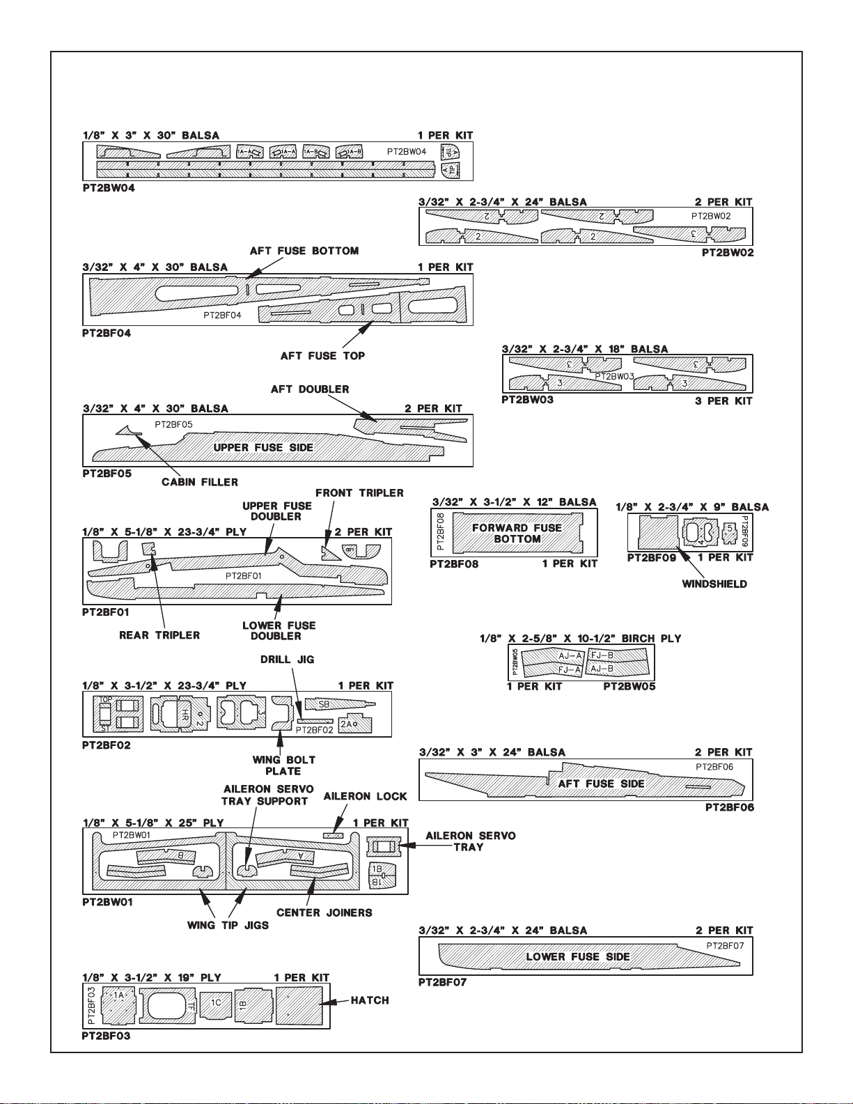
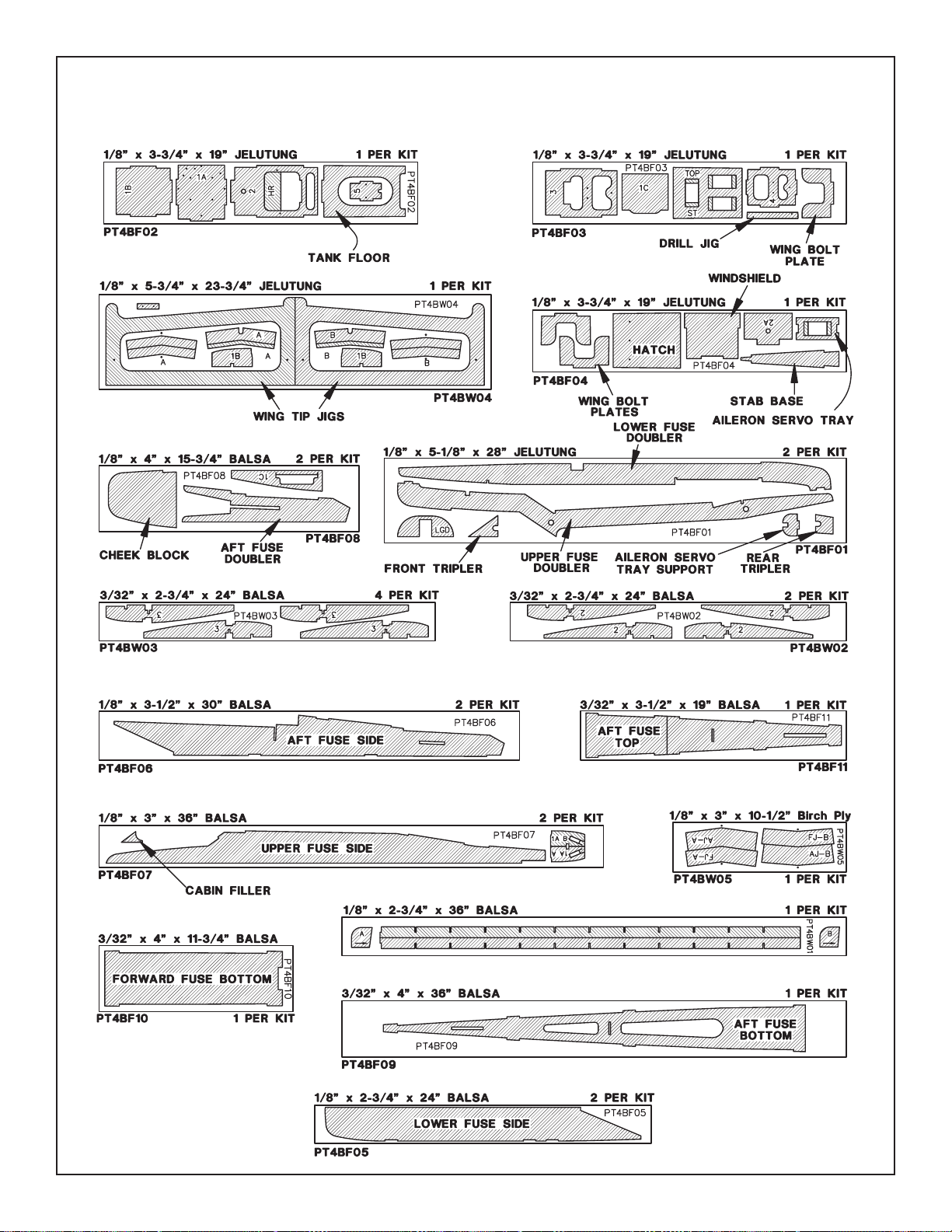
DIE-CUT PATTERNS......................................................10
BUILD THE T AIL SURF ACES.........................................12
Build the Stabilizer and Fin..........................................12
Hinge the Elevator and Rudder....................................12
BUILD THE FUSELAGE.................................................14
Preparation ..................................................................14
Join the Fuselage Sides...............................................17
Install the Main Landing Gear......................................20
Install the Engine .........................................................21
Install the Nose Gear...................................................23
Attach the Stab and Fin to the Fuse ............................24
BUILD THE WING...........................................................26
Preparation ..................................................................26
Build the Wing Panels..................................................27
Join the Wing Panels....................................................28
Prepare the Wing for Sheeting.....................................31
Sheet the Wing.............................................................31
Fit the Aileron Servo Tray.............................................35
Wing Completion..........................................................36
Reinforce the Wing.......................................................39
FINISHING......................................................................40
Final Sanding...............................................................40
Fuelproofing.................................................................40
Balance the Airplane Laterally.....................................40
Cover the Structure......................................................41
Recommended Covering Sequence............................42
FINAL HOOKUPS AND CHECKS..................................43
Join the Control Surfaces.............................................43
Install the Landing Gear...............................................44
Preliminary Radio Installation ......................................44
Balance Y our Model .....................................................47
Final Radio Hook Up....................................................48
Aileron Lock for 3-Channel Operation..........................51
Checks and Final Setup...............................................51
Control Surface Throws................................................52
Ground Stance.............................................................53
PREFLIGHT....................................................................54
Charge the Batteries....................................................54
Balance the Propeller...................................................54
Find a Safe Place to Fly...............................................54
Ground Check the Model.............................................54
Range Check Your Radio.............................................54
Engine Safety Precautions...........................................54
AMA SAFETY CODE .....................................................55
FLYING............................................................................55
Taxiing..........................................................................56
Takeoff..........................................................................56
Flying ...........................................................................56
Landing........................................................................57
SOME MODELING TERMS & TRIVIA............................57
FLIGHT TRIMMING ........................................................61
FLIGHT TRIMMING CHART...........................................62
TWO-VIEW DRAWING...................................................64
Your PT is not a toy, but rather a sophisticated, working
model that functions very much like an actual airplane.
Because of its realistic performance, the PT, if not
assembled and operated correctly, could possibly cause
injury to yourself or spectators and damage property.
To make your R/C modeling experience totally
enjoyable, we recommend that you get help from an
experienced, knowledgeable modeler with assembly
and your first flights.
You'll learn faster and avoid risking
your model before you're truly ready to solo. Your local
hobby shop has information about flying clubs in your area
whose membership includes qualified instructors.
Protect Your Model,Yourself &
Others...Follow This Important
Safety Precaution
IF YOU DON'T READ ANYTHING ELSE...BEFORE YOU
BEGIN CONSTRUCTION, PLEASE READ THIS:
We realize there is a lot to read between the cover and
step one where you finally start gluing parts together (we
wrote it all). Please do not be tempted to just “skim over”
this preliminary reading material – it contains very
important information. Other manufacturers’ instructions
may be shorter, but in the end you'll be glad we gave you
the extra information. It is impor tant to get started on the
right foot if you are to build and fly y our PT successfully – the
rest of your modeling “career” depends on it! Our
suggestion is to forget about building until you have
carefully studied this preliminary information and
skimmed through the construction portion of the manual.
The PT is not at all a difficult model to build but a
methodical, patient outlook is the correct approach to
take – and following this advice is a good place to begin.
2
Table of Contents
Page 3
You can also contact the national Academy of Model
Aeronautics (AMA), which has more than 2,300 chartered
clubs across the country. Through any one of them,
instructor training programs and insured newcomer training
are available.
Contact the AMA at the address or toll-free phone
number below.
Thank you for purchasing the Great Planes PT, the Perfect
Trainer, for possibly your first step into the exciting world of
R/C flying. If you aspire to progress in the hobby and are
using the PT as a “stepping stone” to more advanced
models, then you've made the right decision in not only
choosing an all wood kit, but choosing the PT – a kit that
will teach you many of the building skills required for your
next model. With its “Expert Tips” and thorough, detailed
instructions, this manual encourages you to “exercise and
develop” your building skills which will be of great value in
the future. Although your PT is intended as a trainer, you'll
probably find that long after you've completed it and “moved
on” to other models, you'll dust the PT off and take it out for
a few flights every now and then. A good high wing trainer
such as the PT is always a joy to fly no matter what your
skill level. After all, an air plane so easy to takeoff, fly and
land is a real confidence booster!
The PT family of trainers has been around for more than a
decade. As just about any old pro will tell you, no other
trainer model offers so many important features most
needed by a novice. While R/C flying can be learned by
practically anyone, it does require a fair amount of hand-eye
coordination – a skill that can only be learned by quality
“stick time.” This is where the PTs shine. They are all
designed to be rugged, stable and self-recovering and to
fly slowly enough to allow you time to think about your next
maneuver.
Once your PT has been trimmed for straight and level flight
(by an experienced pilot) you will be able to get out of most
situations by simply letting go of the sticks on your
transmitter. The PT will normally level its own wings and
resume stable flight within 50 - 100 feet.This feature alone
has helped many student pilots master the basics in the
shortest possible time.
The PT is designed for either 3 or 4-channel operation with
two different wing setups (see Wing Configuration on page
4 for further details).You can star t with just rudder, elevator
and throttle control, then add a fourth servo for the ailerons
when you want to refine your skills. The ailerons may be
locked in a neutral position after the wing is assembled, but
can be hooked up in just a few minutes with an additional
servo. We recommend the 3-channel setup for beginners.
Due to the dihedral (upward angle of the wing) built into the
wing and generous rudder size, the turn and bank
response is almost identical to using ailerons. When you
are ready to move up to advanced maneuvers such as
crosswind landings and basic aerobatics, all you have to do
is hook up the ailerons.
If you are already an experienced pilot who is just looking
for a sport model for those lazy summer afternoons, we
provide the necessary information to build the wing with
less dihedral and washout to allow more responsive flight
characteristics. Our goal is for you to experience the fun
and satisfaction that thousands of modelers the world over
enjoy, without the mistakes that have spoiled the hobby
for some.
Please inspect all parts carefully before starting to
build. If any parts are missing, broken or defective, or if
you have any questions about building or flying this
model, please call us at (217) 398-8970 and we'll be
glad to help. If you are calling for replacement parts,
please look up the part numbers and the kit
identification number (stamped on the end of the
carton) and have them ready when calling.
Both the PT-20 and 40 are built from this manual.
Nearly all the parts in the PT ser ies are identical so most
of the differences are only in the sizes and thicknesses of
the pieces – you can't even tell from most of the photos.
When important differences do arise between the 20 and
40, they are clearly indicated so you'll have all the
information you need to build your model.
Important Note About this Manual
INTRODUCTION
Academy of Model Aeronautics
5151 East Memorial Drive
Muncie, IN 47302
Office: (317) 287-1256
Toll Free: (800) 435-9262
Fax:(317) 741-0057
3
Page 4
❏4-Channel radio with 3 or 4 servos;
see Wing
Configuration Section
.
❏ Engine;
see Engine Selection
❏ Spare Glow Plugs (O.S. #8 for 2-stroke engines,
OSMG2691), (O.S.#F for 4-stroke engines,
OSMG2692)
❏ Propeller (Top Flite
®
Power Point®); Refer to your
engine's instructions for proper size
❏ Top Flite Super MonoKote
®
Covering (Approximately
2 rolls);
see Covering
❏ Medium Fuel Tubing (GPMQ4131, 3')
❏ 1/4" Latex Foam Rubber Padding (HCAQ1000)
❏ 1/16" Foam Wing Seating Tape (GPMQ4422)
❏ 4 or 6 oz. Fuel Tank (4 oz. GPMQ4101),
(6 oz. GPMQ4102)
❏ (1) 2" Nose Wheel (GPMQ4221)
❏ (2) 2-1/4" Main Wheels (GPMQ4222)
❏ (6) 5/32" Wheel Collars (GPMQ4306, pkg.of 4)
❏ Fuelproof Paint;
see Finishing
❏ 2" Spinner (GPMQ4510 - white)
❏ #64 Rubber Bands - optional (HCAQ2020);
see Wing Configuration
Accessories Required to Complete
Your PT-20
PREPARATIONS
You also have the option of securing the wing to the
fuselage either with nylon bolts or rubber bands. The
hardware is furnished in the kit for both options. If this is
your first kit we recommend that you go with the rubber
band method. Rubber bands offer two advantages
over bolts: First, the model is easier to build. Second
(this is the important one), rubber bands allow the wing to
shift if your wing tip contacts the ground (or an obstacle)
upon takeoff or landing. Bolts are less forgiving in this
respect, and even a minor whack can cause enough
damage to send your PT back to the shop for repairs.
Wing Configuration
You have a choice in the type of wing to build – the
trainer (“A-wing”) or the spor t (“B-wing”). The A-wing
has more dihedral than the B-wing and will allow your PT
to fly just great as a 3-channel model without functioning
ailerons.We show you how to build the ailerons but “lock”
them down.You can always hook them up later. Building
the A-wing without functioning ailerons saves you a little
money (most four channel systems are sold with three
servos) and building time. If the PT is your first R/C
model we strongly (that's strongly) recommend that you
build the A-wing with more dihedral. If you build the sport
wing you will lose the full benefit of the self-recovery
features of the PT – features that will help you solo faster
and safer.
With the lower dihedral angle of the B-wing you may still
fly your PT without functioning ailerons, but it performs
best with ailerons – this configuration will suit
intermediate and sport flyers.
Engine Selection
There are many engines that will work well in your PT.
For the PT-20 we recommend a 2-stroke sport engine
such as the O.S.®.20 or .25 FP, or the .25 FX (high
performance). Generally, most beginners start out with a
2-stroke engine but for some of those who are a little
more ambitious and “must have” the sound of a
4-stroke, the O.S..26 FS is a good choice.
For the PT-40
we recommend a 2-stroke sport engine
such as the O.S..35 or .40 FP, or the .40 or .46 FX (high
performance). If you choose the 4-stroke option, the O.S.
.40 or .48 FS is a good choice. Super Tigre
™
also offers
the G-40 and G-45 sport engines.
Your dealer will be able to help decide which engine is
the best choice but basically, the O.S. FP series has
proven to be the highest quality yet most economical
choice. The O.S. FX series and the Super Tigre G series
are higher performance engines and might be a little
overkill for a trainer but would be good powerplants for
sport models you may build in the future.
4-Stroke engines are neat because they provide a
realistic sound (realism is generally not a requirement for
a trainer, mind you), are generally quieter than a
2-stroke and appeal to those who are a little more
technically or mechanically minded. 4-Stroke engines do
cost more and require a little more care than a 2-stroke.If
you use a 4-stroke in your PT you will have to relocate
the throttle pushrod exit location on your firewall so
plan ahead.
DECISIONS YOU MUST MAKE
4
Page 5
❏ 4-Channel Radio with 3 or 4 Servos;
see the Wing
Configuration section
❏ Engine;
see Engine Selection
❏ Spare Glow Plugs (O.S. #8 for most 2-stroke engines,
OSMG2691), (O.S.#F for 4-stroke engines,
OSMG2692)
❏ Propeller (Top Flite Power Point); Refer to your
engine's instructions for proper size
❏ Top Flite Super MonoKote covering (Approximately
2 rolls);
see Covering
❏ Medium Fuel Tubing (GPMQ4131, 3')
❏ 1/4" Latex Foam Rubber Padding (HCAQ1000)
❏ 1/16" Foam Wing Seating Tape (GPMQ4422)
❏ 6 or 8 oz. Fuel Tank (6 oz. GPMQ4102),
(8 oz. GPMQ4103)
❏ (1) 2-1/4" Nose Wheel (GPMQ4222)
❏ (2) 2-1/2" Main Wheels (GPMQ4223)
❏ (4) 3/16" Wheel Collars (GPMQ4308)
❏ (2) 5/32" Wheel Collars (GPMQ4306)
❏ 2-1/4" Spinner (GPMQ4515 - white)
❏ #64 Rubber bands - optional (HCAQ2020);
see Wing Configuration
These are the building tools, glues, etc.that you will need to
complete your PT-20 or PT-40.
We recommend Great Planes Pro™CA and Epoxy
❏2 oz.Thin CA (GPMR6003)
❏ 2 oz. Medium CA+ (GPMR6009)
❏ CA Applicator Tips (HCAR3780)
❏ Accelerator (GPMR6035)
❏ 30-Minute Epoxy (GPMR6047)
❏ #1 Hobby Knife Handle (XACR4305)
❏ #11 Blades (HCAR0311, 100 qty.)
❏ Razor Saw
❏ X-Acto
®
(or similar) Building Square (XACR7726)
or Building Triangle (XACR7725)
❏ Medium T-Pins (HCAR5150)
❏ Waxed Paper
❏ Masking Tape
❏ Electric Power Drill
❏ Drill Bits: 1/16", 5/64" (or #47), 3/32", 1/8",
5/32", 3/16", #10 (or 13/64"), 15/64" (or 7/32"),
1/4", 17/64"
❏ Pliers
❏ Scissors
❏ Straightedge
❏ String
❏ Masking tape
❏ Screwdrivers (Phillips and Flat Blade)
❏ Bar Sander or Sanding Block and Sandpaper
(coarse, medium, fine grit);
*see the following
Expert Tip
❏ HobbyLite
™
Balsa Filler (HCAR3401)
❏ Sealing Iron (TOPR2100)
We've listed the following items separately as they are not
absolutely required for you to complete your PT, but these
items will facilitate some of the building procedures or
provide better results. These are items that you will surely
acquire as you progress in the hobby anyway. Don't worry,
even veteran modelers take time to accumulate all the tools
Optional (but highly recommended)
supplies and tools
EX
P
E
RT TIP
Suggested Supplies and Tools
Accessories Required to Complete
Your PT-40
5
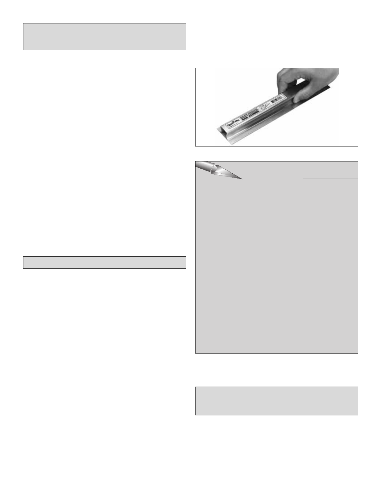
In our busy workshop we use the Great Planes
Easy-Touch™Bar Sanders equipped with Great Planes
#80, #150 and #220-grit Easy-Touch Adhesive-Backed
Sandpaper. Great Planes Easy-Touch Bar Sanders are
made from lightweight, rigid, extruded aluminum and can
be found at most hobby shops. They are available in
three sizes – 5-1/2" (GPMR6169), 11" (GPMR6170) for
most general purpose sanding and 22" (GPMR6172) for
long surfaces such as wing leading edges.The Easy-Touch
Adhesive-Backed Sandpaper comes in 2" x 12' rolls of
80-grit (GPMR6180), 150-grit (GPMR6183) and 220-grit
(GPMR6185) and an assortment of 5-1/2" long strips
(GPMR6189) for the short bar sander.The adhesive-backe d
sandpaper is easy to apply and remove from your
sanding bar when it's time for replacement.
This setup is all that is required for almost any sanding
task. Custom sanding blocks can be made from balsa or
hardwood blocks and sticks for sanding difficult to reach
spots.We also keep some #320-grit wet-or-dry sandpaper
for finish sanding just before covering.
EX
EX
RT TIP
E
P
RT TIP
E
P
Page 6
they'll need to do the best job possible.In some instances it
may not be clear exactly what the optional item is used for
so, where appropriate, we’ve listed the page number and/or
the step where that item is used. While you’re shopping,
you can reference the manual and decide ahead of time
whether not to make the additional purchase.
❏ 6-Minute Epoxy (GPMR6045) see page 7
❏ 1 oz.Thick CA- (GPMR6014) see page 7
❏ Epoxy Brushes (GPMR8060)
❏ Epoxy Mixing Sticks (GPMR8055, qty. 50)
❏ CA Debonder (GPMR6039)
❏ T-Pins (HCAR5100 - small, HCAR5200 - large)
❏ Hot Sock
™
(TOPR2175)
see page 41,
Cover the Structure
❏ Trim Seal Tool (TOPR2200)
see page 41, step B,
Expert Tip – Covering Technique
❏ Heat Gun (TOPR2000)
❏ Single Edge Razor Blades (HCAR0312, 100 qty.)
❏ Razor Plane (MASR1510)
see page 14,
step B, Expert Tip
❏ Z-Bend Pliers (HCAR2000)
see page 23, step 3
❏ Straightedge (Fourmost Non Slip FORR2149)
❏ 3/16" dia. Antenna Tube (GPMQ3710 - or similar)
see page 18, step 9
❏ 1/8" Brass Tube,
see page 38, step 17
❏ Denatured or Isopropyl Alcohol (for epoxy clean-up)
❏ Dremel
®
MultiPro™Tool or similar w/Sanding Drum,
Cutting Burr and Cut-off Wheel
If this is your first model there are a few necessary supplies
and tools that you should gather before going any further.
The single most important item that is required for any
modeling project is a flat work surface.The kitchen table is
generally not a good idea. A space where you can work,
leave stuff out, make a mess, spill glue and paint without
worry, and has adequate ventilation is ideal. Hey, the
garage sounds like a good place!
A workbench can be as simple as a solid flat table or made
from some two-by-fours and a solid core door. Hollow core
interior doors work fine, but the cheaper ones are prone
to warping.
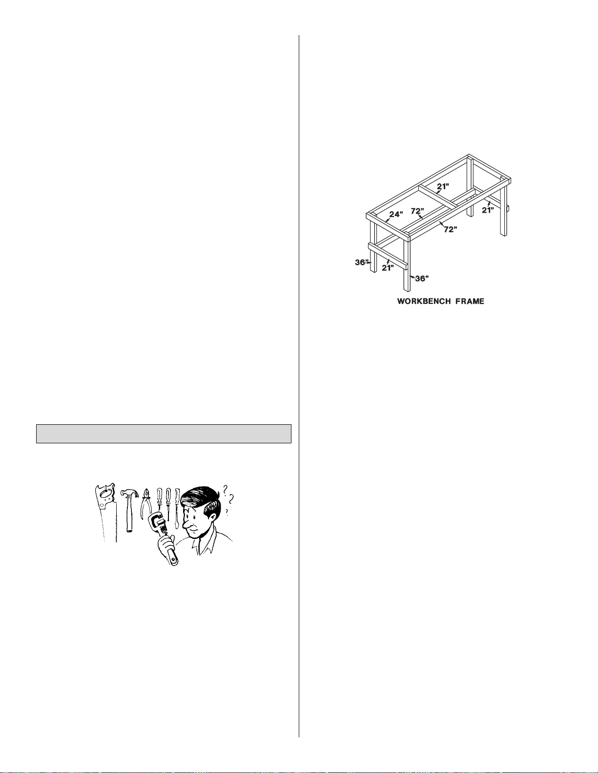
Here is a suggested approach for building an inexpensive
workbench. You will need (7) 6' - two-by-fours of good
quality pine or fir, a 30" x 82" door, some 16d (penny)
common nails, a handsaw and a hammer.
Assemble the workbench as follows:
1) Cut one two-by-four into three sections, two 24" long
and one 21" long.
2) Nail the 24" pieces to the two ends of two straight 6'
pieces to make the frame for the top. Nail the 21" piece
in between the two 6' pieces across the center of the frame.
3) Cut two two-by-fours in half to make four 36" legs. Nail
(or bolt) the four legs to the frame with the 2" side facing
the long sides of the frame.
4) Cut two 21" side rails from one of the remaining boards.
Nail the two boards to the sides of each pair of legs.
5) Nail the last 6' board to the front side of the back legs,
level with the two side pieces. One-by-three cross
braces may be nailed to the back legs for more rigidity.
6) Center the door on the frame and either glue or use
double sided foam back sticky tape to hold it in position.
You will need to cover your work surface with something
you can push pins into.The back side of a 2' x 4' sheet of
ceiling tile makes a great building surface, or if you want to
cover a larger area you can buy a 4' x 8' sheet of Celotex
insulation board from your local building supply store.
Most of the tools listed previously can probably be found
around the house.A few items like a razor saw, hobby knife,
sealing iron, heat gun and glues can be purchased at your
hobby dealer. As you get more involved with the hobby you
will probably want to add a few power tools such as a
Dremel tool, belt sander and a scroll saw, but in the case of
the PTs, everything you need has already been covered.
Setting Up Shop
6
Page 7
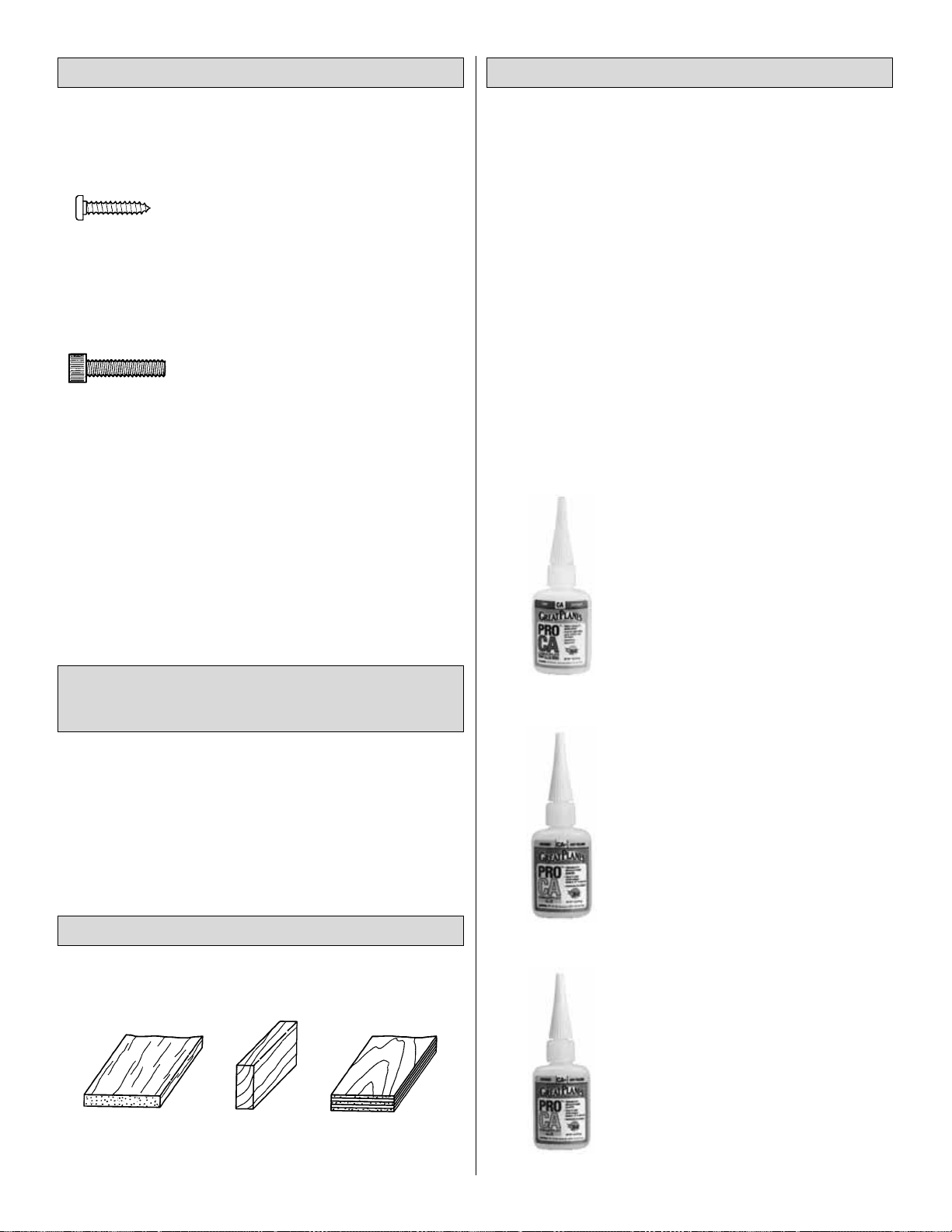
• There are two types of screws used in this kit:
Sheet metal screws are designated by a number and
a length.
For example #4 x 5/8".
Machine screws are designated by a number (threads per
inch) and a length.
For example 4-40 x 3/4".
• When you see the term “test fit” in the instructions, it
means you should first position the part on the assembly
without using any glue, then slightly modify or “custom fit”
the part as necessary for the best fit.
• Whenever just “epoxy” is specified you may use
either
30-minute epoxy or 6-minute epoxy. When 30-minute epoxy
is specified it is highly recommended that you use only
30-minute epoxy because you will need either the working
time and/or the additional strength.
Fuse = Fuselage
Stab = Horizontal stabilizer
Fin = Vertical fin
LE = Leading edge (front)
TE = Trailing edge (rear)
LG = Landing gear
Ply = Plywood
" = Inches
Cyanoacrylate or CA glue has changed the way models
are built more than any other advance in modeling
technology. In the good ol' days, model cement like
Ambroid, Duco, Comet and Sigment were the glues of
choice. They all had a strong odor that could cause
dizziness, dried slowly (compared to CA) and became
brittle with age. CA, on the other hand, is stronger, works
almost instantly and is bottled in three different viscosities
(thicknesses).CA is used for most glue joints, except where
epoxy is specified.CA does emit rather strong fumes (some
say it's like tear gas) as it cures, so rule number one is to
work in a well ventilated area.
All CA glues work best if the joints are smooth and the
parts fit well.
Thin CA is also known as plain CA.
This is the instant variety, used for
most initial assembly and tack gluing.
Thin CA is usually “wicked” into a
tightly fitting joint by putting a few
drops on the seam, then holding the
parts together while the CA
penetrates and bonds the parts.
When gluing plywood or hardwood, a
mist of accelerator (see page 8) will
help the CA work a little better.
CA+ is also known as medium or
gap filling CA. CA+ is used for
surface gluing, filling small gaps
between poorly matched parts and
for general purpose applications. It
cures slower than thin CA, allowing
you to apply a bead to two or three
parts before assembly. Also, because
it cures slower than thin CA, it
penetrates the wood for a stronger
bond. Curing time without accelerator
is 20 - 30 seconds.
CA- or thick CA is used when extra
positioning time is needed. CA- is a
great gap filler and is also used to
make fillets when a little extra
strength is required. Curing time is
about 1 - 2 minutes.
The What and How of Adhesives
Types of Wood
Common Abbreviations Used in this
Manual and on the Plans
Building Notes
7
Balsa Basswood Plywood
#4 x 5/8" Sheet Metal Screw
4-40 x 3/4" Socket Head Cap Screw
Page 8
Accelerator is a liquid chemical for
use in speeding up the cure time of
all CA types. It should be misted on,
not sprayed heavily on the joint. A
typical use of accelerator is to spray
a light mist on a fillet of thick or
medium CA to prevent it from running
or dripping. Another use of accelerator
is to “prime” one of the parts you are
joining before you apply the CA, then
add thick or medium CA to the part
that has not been primed.The CA will
cure immediately when the parts
contact each other, so be careful as
this leaves no time for positioning.
There are special instances where this method comes in
handy but we do not suggest you build your entire model in
this manner. Sometimes, when you glue a joint with thin
CA, the CA is so thin that it is drawn deep into the wood
and away from the glue joint.This can be prevented by first
priming the joint with accelerator, then adding thin CA.The
CA will cure “on the spot” before it has a chance to be
drawn away from the joint.
During the later stages of construction be aware of areas
that you may have sprayed with accelerator. Often times,
residual accelerator, even if sprayed on hours before, may
cause the CA on a nearby joint to cure prematurely and
unexpectedly – it's pretty potent stuff!
Overuse of accelerator may cause CA to bubble and
sometimes change color.A drawback to accelerator can be
that the CA cures before it has time to fully penetrate the
wood, so it should only be used sparingly – only when
necessary. For future reference, keep accelerator away
from clear canopies and other plastic parts such as cowls
and wheel pants. Accelerator will “fog” the butyrate plastic
that most canopies are made from and can cause the ABS
plastic that many cowls are made from to soften.
Epoxy
Great Planes has several Epoxy formulations available for
the modeler.The two most often used epoxies are 6-minute
and 30-minute. Both offer exceptional strength and good
working times. We recommend that you use epoxy when
the joint requires exceptional strength, such as when
installing the firewall, when joining the wing panels and
when installing wing hold-down blocks. As with most
epoxies, you mix equal parts of resin and hardener, stir
well, then apply a thin film to each part. Parts should be
clamped, pinned, taped or weighted in place until fully
cured. Before the epoxy cures, clean off any excess with a
paper towel. A word of caution about mixing epoxy – don't
use extra hardener in the hopes of making the mixture
harder or work faster. Just about all epoxies work best with
exactly a 50/50 mixture. When you increase the amount of
hardener you run the risk of causing the cured epoxy to
become either brittle or rubbery – neither being as strong as
a properly mixed batch.
A word about safety!
After applying CA, step back or look away from the work
to avoid the puff of vapors. All CA glues will bond skin
almost immediately.If this should happen, CA Debonder
(available from your hobby dealer) or acetone fingernail
polish remover will dissolve the CA if allowed to soak
into the bond for a few minutes. Don't use vigorous
means to separate a skin bond. Never point the CA
applicator tip toward your face and be especially careful
when opening a clogged tip. In case of eye contact,
flush thoroughly with water, then seek medical attention,
but don't panic. Please, keep CA (and all other
modeling chemicals) out of the reach of children.
8
Metric Conversion
Page 9
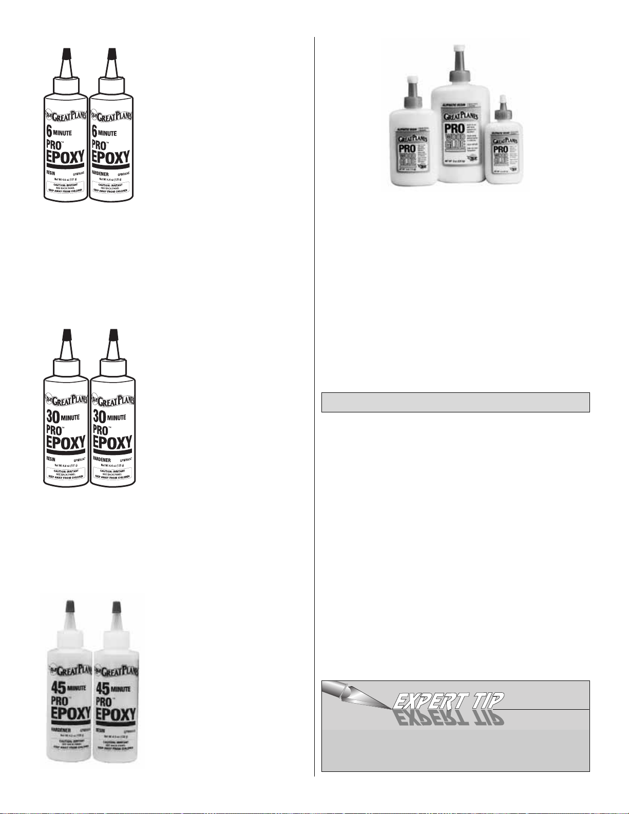
6-Minute epoxy is used for simple,
small gluing operations where
elaborate alignment is not required.
Working time (before it's too gooey
to use) is about 5 minutes, handling
time 15 minutes and it's fully cured
in about 1 hour.
30-Minute epoxy is used for extra
strength (because it can penetrate
longer) and where several parts
must be aligned and checked
before it cures. Working time is
about 25 minutes, handling time 2
hours and it's fully cured in 8 hours.
45-Minute epoxy offers plenty of
responding time plus incredible
strength. It is ideal for sheeting
balsa wood to foam core wings
and other high stress areas.
Working time is about 45-50
minutes, handling time 2 hours and
it's fully cured overnight.
Great Planes Pro Wood Glue is an Aliphatic resin glue that
works well on all types of wood. It is non-toxic, virtually
odorless and dries clear. Some people are sensitive to the
fumes and sanding dust derived from CA, so this is a good
alternative for general modeling use. Its only drawback is
that it is slow to cure, requiring the parts to be securely
clamped, pinned or taped while the glue dries. In some
cases this is an advantage as it allows plenty of time for
accurate positioning of parts. For future reference, aliphatic
resin also sands easier than CA and is ideal for joining wing
sheeting planks.
Okay, you've got your work space ready, your tools are at
hand and you know how to choose and use the right glue
for the job. Let's get started!
❏ 1. Unroll the plan sheets. Reroll the plans inside out to
make them lie flat.
❏ 2. Remove all parts from the box. As you do, figure out
the name of each part by comparing it with the plans and
the parts list included with this kit. Using a felt-tip or
ballpoint pen, lightly write the part name or size on each
piece to avoid confusion later. Use the die-cut patterns
shown on pages 10 and 11 to identify the die-cut parts and
mark them before removing them from the sheet. Save all
scraps. If any of the die-cut parts are difficult to punch out,
do not force them! Instead, cut around the parts with a
hobby knife. After punching out the die-cut par ts, use your
bar sander or sanding block to lightly sand the edges to
remove any die-cutting irregularities or slivers.
❏3. As you identify and mark the parts, separate them into
groups, such as fuse (fuselage), wing, fin, stab (stabilizer)
and hardware.
Get Ready to Build
9
Zipper-top food storage bags are handy to store your
parts as you sort, identify and separate them into
subassemblies.
Page 10
10
DIE-CUT PATTERNS FOR PT-20
Page 11
11
DIE-CUT PATTERNS FOR PT-40
Page 12
12
Work on a flat surface over the plans covered with waxed
paper. Frequently refer to the plans to identify the parts and
their locations.
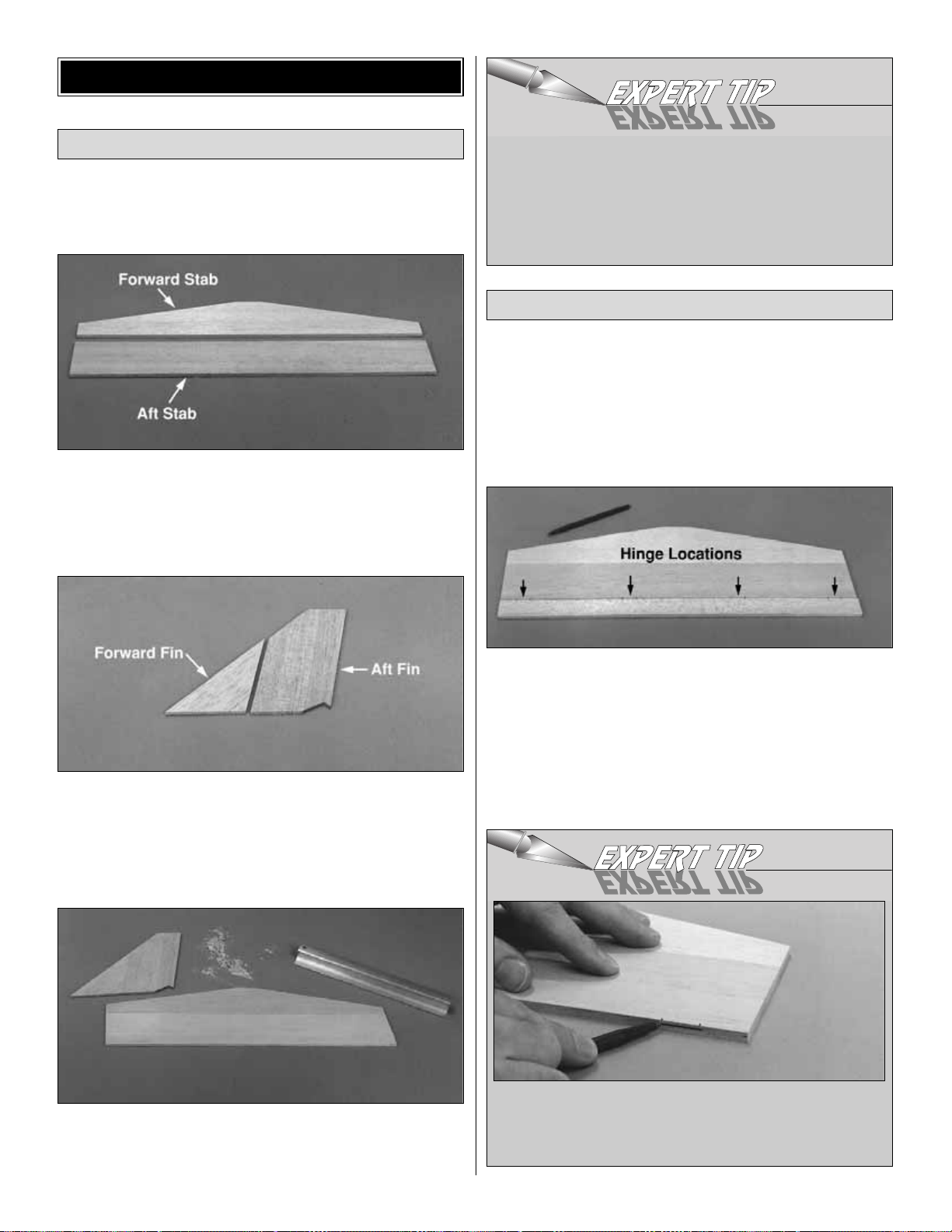
❏1. Locate the shaped balsa forward and aft stab. Check
their fit and sand the mating edges if needed. Apply a light
bead of medium CA to the mating edges and glue them
together. Immediately wipe away any excess CA before it
cures.
❏ 2. Locate the shaped balsa forward and aft fin. Check
their fit and sand the mating edges if needed.Work over the
plans (don’t forget the waxed paper), then glue the two
parts together as you did the stab parts. Immediately wipe
away any excess CA from the surface before it cures.
❏3. See the Expert Tip that follows, then sand the stab and
fin flat and smooth with sharp 220-gr it sandpaper and your
bar sander or a sanding block.
Note: One of the best ways to enhance the finish and
appearance of your model is to do a good hinging job.
Properly aligned hinge slots and secure hinges will
eliminate problems at the flying field. Follow these
instructions and take your time in order to avoid crooked or
misaligned hinge slots that can lead to tight control
surfaces or loose hinges.
❏ 1. Locate the balsa elevator (refer to the plan for size
and shape). Use a ballpoint pen to lightly mark the location
of the hinges on the stab and the elevator where they are
shown on the plan.
❏ 2. Refer to the Expert Tip below and mark the location
of each hinge slot on the trailing edge of the stab.
Hinge The Elevator and Rudder
Build The Stabilizer and Fin
BUILD THE T AIL SURFACES
It is more important to keep the thickness of the entire
stab and fin constant than it is to completely eliminate
the glue joint. Don’t spend too much time sanding in
one particular spot where the seam might not be
perfect – otherwise that area of the stab or fin will
become thinner than the rest. This is a little more
important on the PT-20.
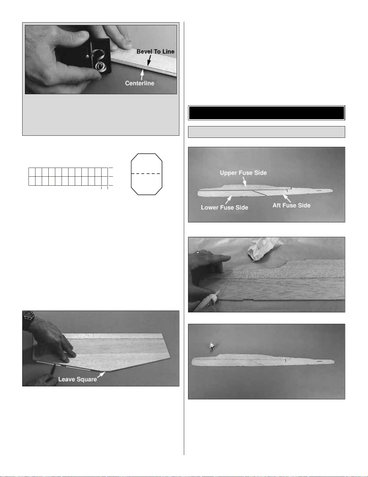
HOW TO DRAW A CENTERLINE
A. Place the part on a flat surface and draw a line
approximately 1" long with a ballpoint pen (a Bic Stik
works well).
Page 13
❏3. Use the same procedure to mark the centerline on the
entire length of the leading edge of the elevator.
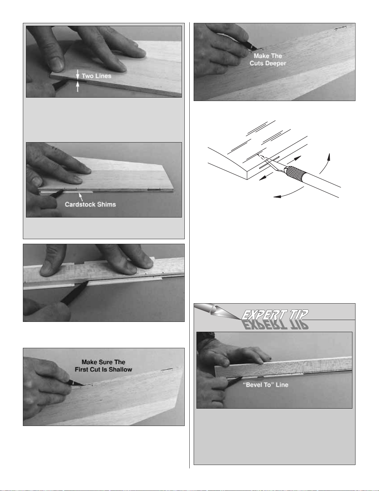
❏ 4. Cut the hinge slots in the elevator and stabilizer using
a #11 blade. Begin by carefully cutting a very shallow slit
at the hinge location. This first cut will establish the
location of the hinge slot, so concentrate on staying on the
centerline and don’t cut too deep!
❏ 5. Make three or four more cuts on the same line, going
slightly deeper each time. As you make these additional
cuts, go straight into the wood. Continue this process while
“wiggling” the knife handle from side to side until the
blade has reached the proper depth for the hinge.
❏ 6. Refer to the Expert Tip below and sand the LE of the
elevator and rudder to a “V” as shown on the plans. Leave
the TE of the stab and fin squared off.
13
B. Confirm that the line you have drawn is on center by
flipping the part over and drawing a second line over the
first. If the line is on center, you will see only one line.
Draw a centerline at each hinge location. If you see two
lines (as in the photo) go to step C.
HOW TO BEVEL THE LEADING EDGES
A. Place the leading edge of the elevator on your work
surface and use your ballpoint pen to mark a “bevel to”
line on both sides about 3/32" high. Note: You will
probably have to shim the elevator (similar to the way
you did for drawing the hinging centerlines) so your bevel
to line is not too far away from the leading edge.
C. Place shims such as business cards or playing cards
under the stab until you can mark the centerline.
CUT HINGE SLOT
WITH HOBBY KNIFE
AND #11 BLADE
Page 14
❏ 7. Cut the hinges for the elevator and the rudder from
the supplied 2" x 9" hinge material, then snip off the
corners so they go into the slot easier. Note: If you are
building the PT-20, make the hinge for the bottom of the
rudder 3/8" wide.
❏ 8. Temporarily join the elevator to the stab with the
hinges and widen any slots if required so they all match up.
❏ 9.Return to step 1 and use the same procedures to
hinge the rudder and fin. Note: If you are building the
PT-20, make the bottom hinge slot in the rudder 3/8" wide.
❏ 10. Use the same “centerline technique” you used when
you made the hinge slots to mark the perimeter of the
stabilizer and elevator.Round the perimeter of the stab and
elevator with your bar sander and 220-grit sandpaper using
the centerline as a guide. On the stab, keep the trailing
edge and the “flattened-off” center portion of the leading
edge square. Finish-sand the stab and elevator with 320-grit
sandpaper. Hint: Leave the elevator attached to the stab
during sanding so the ends will be rounded off the same.
Congratulations! You’ve made it through the first stage
and if this is your first model you should be proud of
yourself.You should also have learned a few “tricks of the
trade” used by the guys that designed this kit. Remember,
all of these helpful tips are the same methods that we use
to build our award winning models and are tips that you can
use and refine for future, more ambitious building projects!
❏ 1. Test fit the die-cut balsa fuse side pieces as shown in
the photo. Sand the edges as necessar y for a good fit.
When satisfied with the fit, make a fuse side using thin CA
to glue the parts together over waxed paper. Make a
second fuse side in the same manner.Note: It is easiest to
first glue the aft fuse side to the upper fuse side, then
glue the lower fuse side.
Preparation
BUILD THE FUSELAGE
14
B. Use a razor plane or your bar sander with 150-grit
sandpaper to make the “V” on the rudder and elevator.
Use the “bevel to” lines and the previously drawn
centerline as a guide to keep the angle of the “V”
constant and centered.
1"
1"
3/4"
Page 15
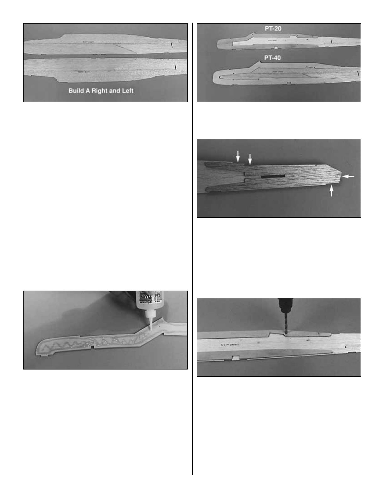
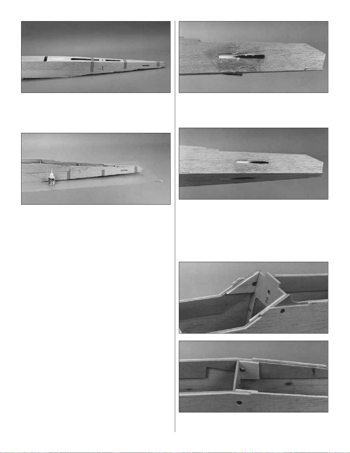
❏ 2. Examine the two fuse sides for blemishes, then
position them on your workbench exactly as shown in the
photo with the best-looking sides facing down. You must
build a right and a left side so be sure that the sides are
mirrored as you look at them. Mark the inside surfaces as
“right” and “left.”
❏ 3. Lightly sand the edges of the die-cut 1/8" plywood
upper and lower fuse doublers to remove any slivers or
die-cutting irregularities.
Work especially carefully during the following two
steps. You must accurately position the fuse doublers on
the fuselage sides as this is the most critical step in building
a straight fuselage.
❏❏4. Still working over waxed paper, test fit, then glue a
die-cut 1/8" plywood upper fuse doubler to the inside of
the right fuselage side with medium CA. See the photo at
step 6. The top edge of the doubler should align with the
top of the fuse side at the wing saddle. The balsa side
behind the wing saddle protr udes above the doubler
by 3/32".
❏❏5. Test fit the lower fuse doubler in the notch of the
top doubler with 3/32" of the balsa fuselage side showing
below the doubler when it’s properly aligned. Glue the lower
doubler in position with medium CA the same way as you
did the upper doubler. See the photo at step 6.
❏ 6. Repeat steps 4 and 5 to glue the doublers to the
inside of left fuse side. Be sure you are building a right
and a left.
❏❏7. Test fit the die-cut balsa aft fuse doubler on the
inside of the right fuselage side.The “steps” in the front and
rear of the doubler should align with the fuselage side and
the aft end of the doubler and the fuselage side should also
align. Apply medium CA to the doubler, then glue it in
position. Repeat for the other fuselage side.
Skip step #8 if you will be using bolts to mount
your wing.
❏ 8. If you will be installing the dowels for rubber band
wing attachment, drill 1/4" holes through the fuse sides at
each punch mark in the upper doublers. Use a backup
block of scrap wood under the fuse side to prevent splitting
the balsa as the drill bit goes through (and to keep from
drilling into your table).
❏ 9. Locate the three die-cut 1/8" plywood firewall formers
F-1A, F-1B and F-1C and the three die-cut 1/8" plywood
wing bolt plates. Note: You need the wing bolt plates for
strength even if you will be using rubber bands to attach
the wing.
15
Page 16
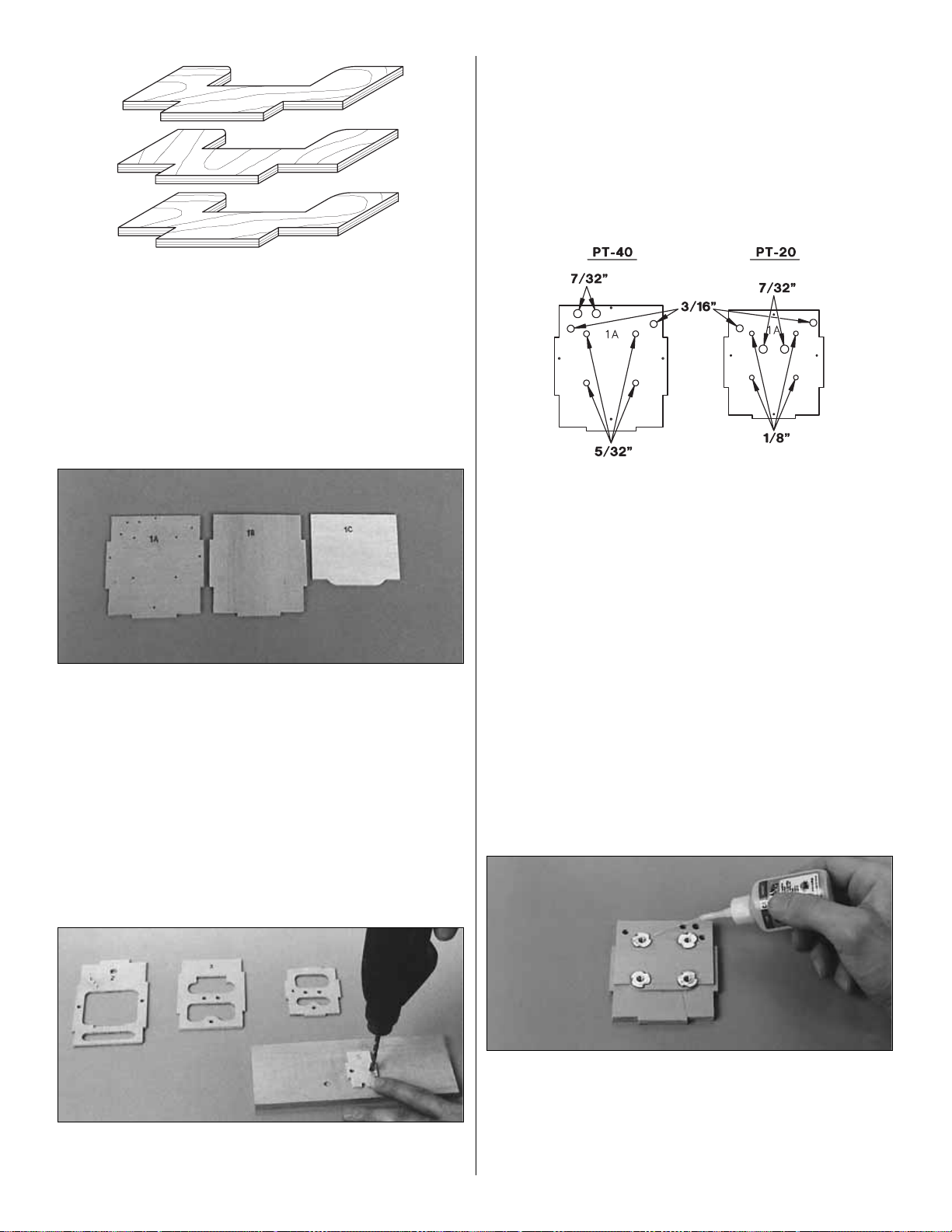
❏ 10. Notice that two pieces of the wing bolt plate
assembly have grain running in one direction while the third
piece has grain running opposite to the first two. The odd
one goes in the center of the “sandwich.” Mix about 1/4 oz.
of 30-minute epoxy and glue the bolt plates together as
shown (the extra epoxy will be used in the next step). This
assembly must be clamped together with C-clamps or
weighted down while the epoxy cures. If you use weights,
be sure the pieces do not slide and shift when you add
the weights.
❏ 11. Use the remaining 30-minute epoxy to glue F-1A,
F-1B and F-1C together. Be sure that F-1A (the one with
the punch marks) is on top of the stack with the punch
marks facing outward, the locking tabs are aligned, and
that F-1C is flush with the top edge of the assembly (see
the fuse plan). This assembly must be held together with
clamps, or weighted down while the epoxy cures. Note: If
the three formers are wrapped, simply clamping them
together may not necessarily “cancel out” the warps. It is
best to clamp the assembly over waxed paper to a flat
board or table. Allow the epoxy to fully cure before
removing the clamps.
❏ 12. Position the die-cut 1/8" plywood formers F-2
through F-5 over a piece of scrap wood, then drill a 3/16"
hole through each of the punch marks (former F-4 on the
PT-20 is balsa). Do not drill the F-1 assembly during this
step. Note: When punching out former F-2 from the die
sheet, don’t accidentally throw away the plywood hatch
retainer as it may be easily mistaken for scrap. Refer to the
die drawings.
❏ 13. Refer to the sketch, then drill two 3/16" pushrod tube
holes through the firewall where indicated. Change your bit
size to 7/32" (or 15/64" for perfection) and drill the two fuel
tube holes where indicated. Finally, drill four 5/32" holes
(1/8" if you’re building the PT-20) for the engine mount blind
nuts. Note: The remaining four punch marks around the
perimeter of the firewall could be used for locating the
center of the firewall should you choose to use a different
engine mount.
❏ 14. Clean up any slivers from around the holes you
drilled and also the edges of the formers with a bar sander
and 220-grit sandpaper.
❏ 15. Press a 6-32 blind nut (4-40 if you’re building the
PT-20) into one of the holes in the back of the firewall
(F-1C), then tap it gently with a hammer until it is fully
seated. Put a few drops of thin CA on the outer edge of the
flange to secure the blind nut. Install the remaining three
blind nuts the same way.
16
Page 17
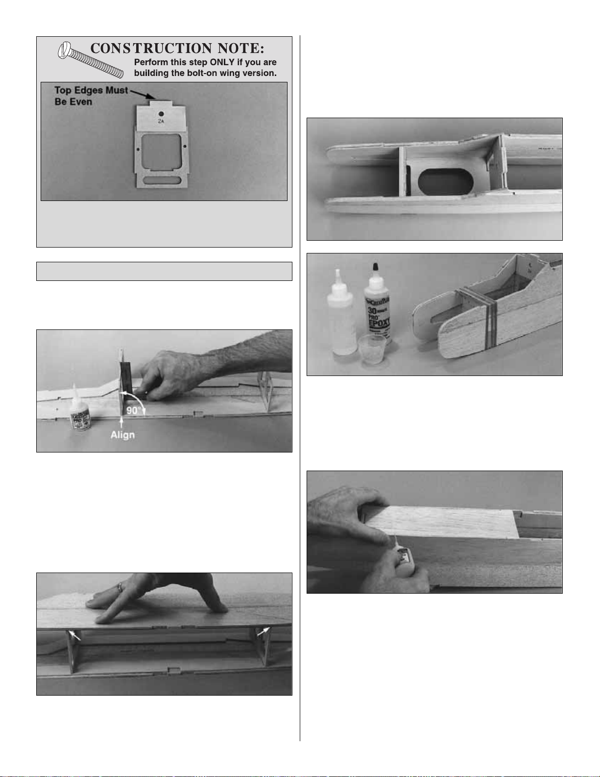
IMPORTANT: Position all of the formers with the embossed
numbers facing the front of the model.
❏1.Test fit the die-cut 1/8" plywood formers F-2 and F-3 in
position on the right and left fuse sides. Be sure the
bottoms of the formers line up with the bottom of the
doublers on both fuselage sides.
For the bolt-on wing
version, the F-2A former must face toward the front of the
model.
Glue F-2 and F-3 to the right fuse side as shown
with medium CA. Hold F-2 and F-3 vertical with a triangle
or building square while the CA cures.
❏ 2. Glue the left fuse side to formers F-2 and F-3,
making sure the fuse sides are aligned and the bottoms of
the formers are flush with the bottom of the doublers.
❏3.Test fit, but do not glue, the die-cut 1/8" plywood tank
floor and the firewall assembly between the fuse sides.The
tab at the rear end of the tank floor should fit into the notch
at the bottom of F-2 and the front of the tank floor should fit
under F-1C on the back of the firewall assembly. Make any
adjustments if required to the firewall sides or the tank floor.
❏ 4. With the tank floor installed (but not yet glued), glue
the firewall assembly in position with 30-minute epoxy.
Use rubber bands and/or masking tape to clamp the
fuselage sides together while the epoxy cures. After the
epoxy has cured, glue the tank floor in position with
medium CA.
❏ 5. Test fit the die-cut 3/32" balsa front fuse bottom into
the notches and recess on the bottom of the fuse. If you
have your battery pack handy, simulate installing it under
the tank floor as you would if the model was completed. A
500 mAh flat pack wrapped in foam will fit but if you have a
larger battery pack you may wish to enlarge the opening in
the tank floor. Make modifications before you glue the front
fuse bottom in position. When satisfied with the fit, glue the
front fuse bottom in position with thin CA along both outside
edges.Turn the fuse over, then wick thin CA into the inside
joints between the bottom and the formers. Follow with
medium or thick CA in any open joints.
Join the Fuselage Sides
17
❏ 16. Glue the die-cut 1/8" plywood former doubler
F-2A to the front of former F-2 (that’s the side with the
punched number) so the top edges are even.
Page 18
❏ 6. Test fit the die-cut 3/32" balsa rear fuse bottom
between the fuse sides. Temporarily hold the bottom in
position with a few strips of masking tape.
❏ 7. Install the die-cut 1/8" formers F-4 and F-5 in the
notches of the fuse sides and bottom. Be sure that the
antenna tube hole is toward the bottom of the fuse. Use
more masking tape to hold the formers tightly in position.
When you are satisfied that everything is square and true,
place the fuse on waxed paper, then wick thin CA into the
joints (from the inside) between the fuse sides, bottom and
the formers. As you apply glue, press down on the fuselage
to hold it square.
❏ 8. Apply medium CA along all of the inside joints to
permanently secure the framework.Remove the masking tape.
❏ 9. Cut the two 36" plastic outer pushrod tubes to 26"
for the PT 40 (24-1/4" for the PT 20). One tube will be used
as the elevator pushrod guide tube and the other will be
used as the rudder pushrod guide tube. Make the
antenna tube (optional) from any type of 3/16" pushrod
tube (not included). We recommend purchasing a Great
Planes 36" flexible pushrod set (GPMQ3710) and using
one of the outer tubes from the set. Save the scrap pieces
from the elevator and rudder tubes for use later.
❏ 10. Sand the outside of each tube with 150-grit
sandpaper so glue will stick to them. Slide the antenna
tube (if used) through the bottom hole in formers F-3, F-4
and F-5 and through the exit slot in the bottom of the fuse.
Slide the pushrod tubes through the upper holes in the
formers and out through the exit slots at the rear of the
fuse. All of the tubes should protrude about 1/2" past the
rear end of the slots. Use medium CA to glue the pushrod
tubes to each former and the exit slots.
❏ 11. Use HobbyLite filler to fill the gap around the
pushrod tubes on the outside of the fuselage.
❏ 12. After the filler has fully cured, sand the protruding
pushrod tubes and the filler so it is flush with the fuselage.
Skip step #13 if you will be using bolts to mount
your wing.
❏ 13. Glue the die-cut 1/8" plywood front and rear dowel
triplers in position with medium CA.
18
Page 19
❏ 14. Hold the die-cut 3/32" balsa fuse top at the edge of
your work table, then gently “crack” the wood along the diecut score line. Do not break the part in two. Hint: Bend
the fuse top away from the side that has the score
on it.
❏15. Use a straightedge and a ballpoint pen to draw a line
across the notches on the fuse top at the score line. Cut
two 1/4" wide strips from 3/32" scrap balsa and glue them
to the inside of the fuse top on either side of the score line
between the lines you marked. Note: If building the PT-20,
the 3/32" balsa strips must be shorter than the ones shown
in the photo to fit between the fuselage doublers.
❏ 16. Test fit the fuse top to the fuselage. Glue it in position
by wicking thin CA into the joint between the top, former tabs,
and the sides.Follow with medium CA to fill in any gaps.
❏ 17. Use epoxy to glue the wing bolt plate assembly into
the notches of the plywood doublers and F-3.
We
recommend that you perform this step even if you are not
going to use the bolt-on wing option.
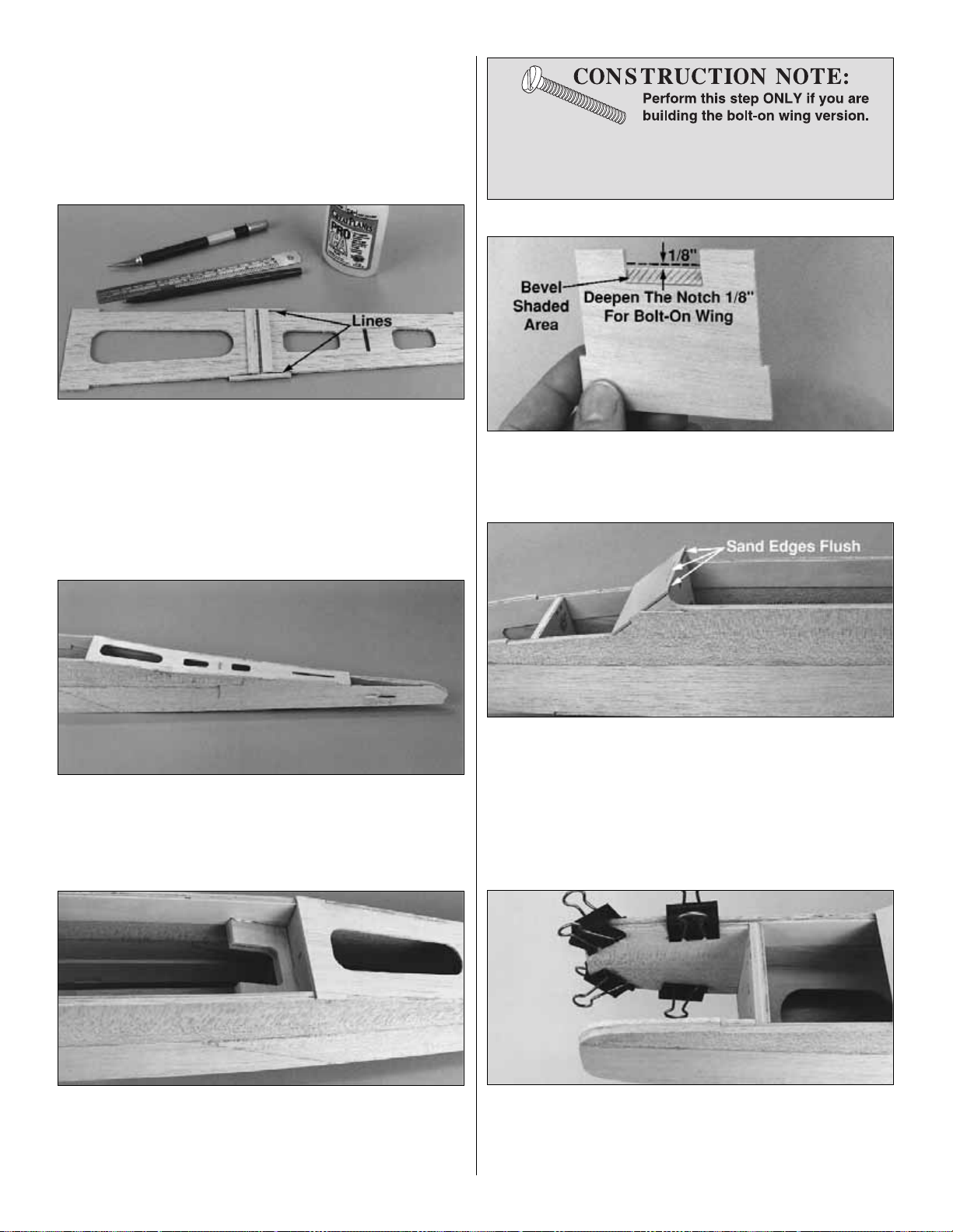
❏ 19. Carefully sand or cut a bevel along the bottom of the
notch in the windshield. This bevel will allow the windshield
to fit flush against F-2.
❏ 20. When the windshield fits properly, glue it in position
with medium CA. Sand the top of former F-2 (A) flush with
the front surface of the windshield. Sand the rear of the
windshield overhang flush with the back of F-2.
Skip step #21 if you are building the PT-20.
❏ 21. Test fit the die-cut 1/8" balsa nose blocks in the
engine compartment, then glue them in position with epoxy.
After the epoxy has cured, sand the outside edges flush
with the fuse.
19
❏ 18. Increase the depth of the notch in the die-cut 1/8"
windshield by 1/8" to allow for F-2A (the windshield for
the PT-20 is balsa). See the following photo.
Page 20
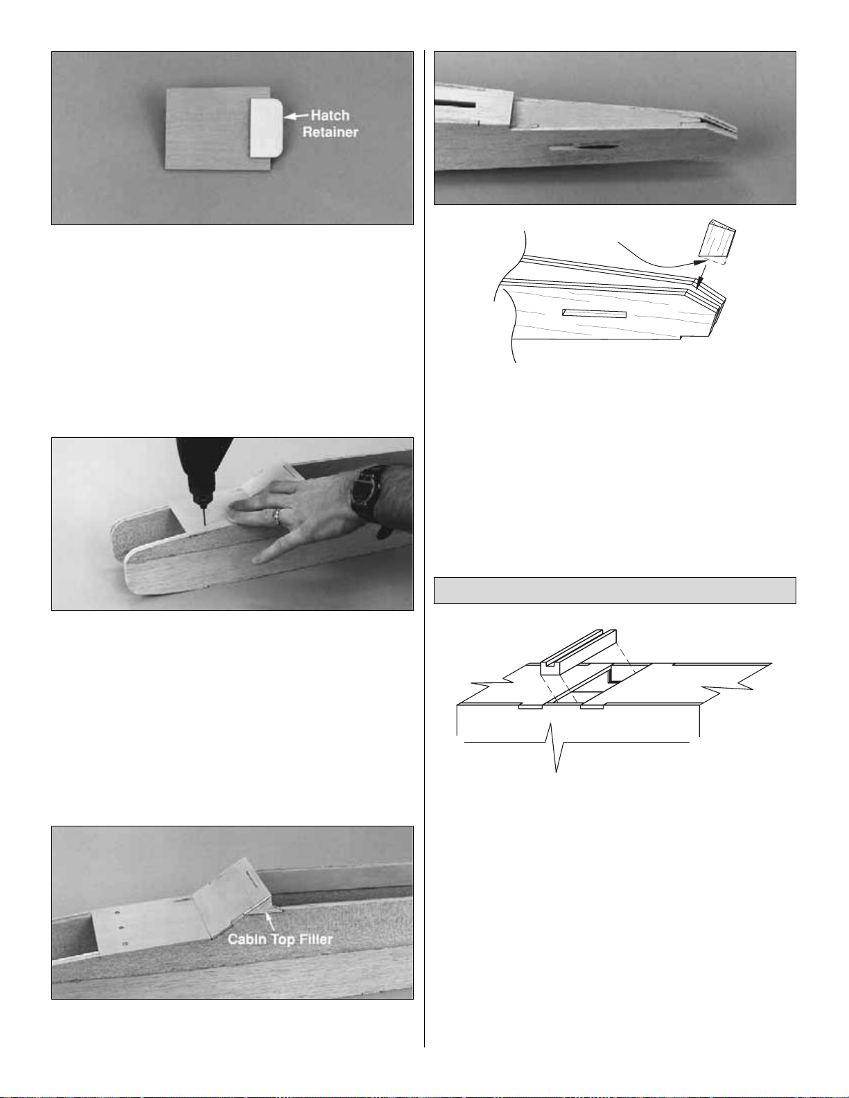
❏ 22. Locate the die-cut 1/8" plywood hatch retainer
(HR). Center the hatch retainer on the bottom (unpunched
surface) of the die-cut 1/8" plywood tank compartment
hatch with approximately 3/8" protruding from the rear,
then glue it in position.
❏ 23. Position the hatch on the fuselage and drill 1/16"
holes through the punch marks in the hatch into the firewall.
Remove the hatch, then enlarge the holes in the hatch
only with a 3/32" drill bit. Temporarily mount the hatch to
the fuselage with #2 x 3/8" screws.
❏ 24. Glue the two die-cut balsa cabin top fillers in the
notches on both sides of the windshield.
❏ 25. Test fit, then glue the die-cut stab base and the
tapered balsa tail wedge into the aft end of the fuselage.
Trim the tail wedge as necessary for a good fit.
Skip step #26 if you are building the bolt-on wing version.
❏ 26. Slightly chamfer the ends of the two wing dowels,
then test fit them through the holes in the fuse. Hint: Run a
1/4" drill through the fuse sides to make sure the holes are
all lined up. Remove the dowels until the model is
covered. You will be instructed when to glue the dowels in.
❏ 1. Test fit, but do not glue, the grooved hardwood
landing gear (LG) rail in the slot on the bottom of the fuse.
It should fit snugly in the space between the ends of the
bottom sheeting and the notches in the fuse sides.
❏ 2. See the following photo at step 4. While the rail is in
position (but not yet glued) test fit the two die-cut 1/8"
plywood landing gear doublers (LGD) and the hardwood
landing gear blocks. Note: The grain direction of the LG
blocks is vertical (as shown on the plan).
❏ 3. Remove all the landing gear parts, then mix enough
30-minute epoxy to glue the LG rail and the LG blocks.Glue
the LG rail to the fuse sides and fuse doublers with epoxy,
then glue the LG doublers in position with medium CA.
Immediately proceed to the next step.
Install the Main Landing Gear
20
Trim to fit bottom
of fuselage
Page 21

❏ 4. Glue in the LG blocks with 30-minute epoxy. Wedge a
scrap balsa stick between the blocks to hold them in
position while the epoxy cures. For added clamping power,
turn the fuselage over and place weights on top of the LG
rail to hold it down.
❏ 5. After the epoxy has cured, glue the front and aft fuse
bottoms to the LG rail with medium CA.
❏ 6. For this step, the epoxy must be fully cured. Fit the
die-cut 1/8" plywood landing gear drill guide into the
groove in the rail (it doesn’t matter which way it goes in).
Drill a 3/32" pilot hole through the rails and landing gear
blocks at each of the punch marks on the guide. Use care
to drill the holes perpendicular to the fuse bottom. Look
inside the fuse to make sure you drilled the holes straight
into the hardwood blocks.
❏ 7. Remove the drill guide, then redrill the holes with a
3/16" bit (5/32" if you are building the PT-20) making
angular adjustments if necessary. Hint: If you have a
numbered drill set, you may drill the holes with a #12 drill bit
(#22 for the PT-20) for easier installation of the landing gear.
❏ 8. Car ve a radius in each LG rail hole toward the center
of the fuse to allow the LG wire to fully seat in the holes.
Cut a round notch in each fuse side to clear the LG.Test fit
the main landing g ear. It’s helpful if you use a file to
remove any burrs or sharp edges from the ends of the wire.
After fitting the LG in position, you may remove it and set it
aside until final assembly.
❏ 1. Remove the “spreader bar” from each mount half.
Carefully trim any extra material left by the spreader bar or
flashing from any other rough edges so the mount halves
will fit together.Fit the mount halves together.
❏2. Remove the fuel compartment hatch.Use a pen and a
straightedge to mark the vertical centerline on the firewall
by drawing a line connecting the punch marks on the top
and bottom of the firewall.
❏ 3. Temporarily bolt the engine mount to the firewall using
four 6-32 x 1" screws with #6 flat washers (use 4-40 x 1"
screws with #4 washers if you are building the PT-20). Don’t
tighten the screws completely until after the engine has
been positioned.
Install the Engine
Note: If you will be installing a 4-stroke engine you need
to plan ahead for servo location and pushrod routing.
Refer to the sketch on page 46 and the fuselage plans
for the 2-stroke/4-stroke servo and pushrod setup.
21
Page 22

Note: You will need your engine for the following steps.
From here on it is a good idea to plug the holes in your
engine so balsa dust cannot get in. Stuff a piece of paper
towel into the exhaust and carburetor venturi to seal
them off.
❏ 4. Remove the needle valve from your engine. Position
the engine on the engine mount and adjust the engine
mount halves until the engine mounting lugs will sit flat on
the rails. Position the mount so the firewall centerline is
centered between the “tick” marks on the mount. Tighten
the screws to hold the mount firmly in position against
the firewall.
❏ 5. Mount the spinner back plate on your engine. If you’re
building the PT-40 position the engine so that the spinner
backplate is 4-1/2" (115mm) from the firewall. If you’re
building the PT-20, position the engine so that the spinner
pack plate is 4" (102mm) from the firewall. Carefully mark
the engine mounting holes on the rails with a sharpened
piece of wire or a pencil. Note: If installing a 4-stroke
engine, the engine may be forward of the recommended
position to allow for the choke mechanism. This is
acceptable and will not cause a balance problem.
❏ 6. Remove the engine and engine mount from the fuse.
Use a center punch or sharpened nail to "dimple" the marks
on the rails, then drill a 3/32" hole through the rails at each
punch mark. If you have access to a drill press, this is the
best tool for the job. However, if you are using a hand-held
electric drill, try to keep the bit perpendicular to the rails.
❏ 7. Install a threaded ball stud in the bottom hole of the
carburetor arm of your engine and secure it with a 0-80 nut
and a drop of epoxy or thread locking compound. Fasten
the engine to the mount with four #4 x 5/8" screws
included in this kit (or your 4-40 screws). Hint: Add a drop
of household oil to the #4 sheet metal screws to make them
easier to screw into the mount.
❏ 8. Carefully and neatly cut away some of the fuselage
side so you can reach the needle valve. A Dremel tool with
a sanding drum works well for this.
❏ 9. Remove some of the fuselage side to clear the
muffler. There should be approximately 1/8" clearance
between the muffler and the fuselage.
❏ 10. From one of the leftover pieces of outer pushrod
tube (you saved from the elevator and rudder guide tubes)
cut a piece for the throttle guide tube. It should extend
1/2" past the firewall and 1/2" aft of F-2.Temporarily install
the throttle guide tube through the holes in the firewall
and F-2.
EX
P
E
RT TIP
22
Some modelers prefer to secure the engine to the mount
with machine screws (not supplied) because they are
easier to screw in.For both the PT-20 and 40, 4-40 x 3/4"
screws are recommended. Use a #48 drill bit to drill the
holes, then tap the threads with a 4-40 tap.
EX
EX
RT TIP
E
P
RT TIP
E
P
Page 23

❏ 11. From the other piece of outer pushrod tube, cut the
nose steering guide tube. It should be flush with the front
of the firewall and extend 1/2" aft of F-2.Temporarily install
the nose steering guide tube in the firewall and F-2.
❏ 12. Cut 14" from the threaded end of a 36" threaded
wire pushrod (after cutting you should have a 14" long
piece of wire threaded at one end and a non-threaded
piece 22" long). The threaded end wire is the throttle
pushrod and the non-threaded piece is the nose g ear
pushrod. Screw a ball link about 14 full tur ns onto the
threaded pushrod wire. Save the nose gear pushrod
for later.
❏ 13. Inser t the throttle pushrod through the pushrod tube.
Make one downward bend in the pushrod so that the ball
link will meet the ball stud on the engine without binding.
Don’t snap the ball link onto the ball until later. Bend the
wire away from the fuselage side about 1" aft of F-2. The
final adjustments will be done during the radio installation.
❏ 1. Remove the engine from the engine mount. Slide a
5/32" wheel collar (included with this kit) with a set screw
installed on the nose gear, then install the nose gear into
the engine mount so 1/4" protrudes above the engine mount.
❏ 2. Position the wheel collar so it is snug against the
bottom of the engine mount, then temporarily tighten the
set screw to lock the wheel collar in position.
Look ahead to
the photo at step 5 for more information.
❏ 3. Use your “Z-bend” pliers or follow the Expert Tip
that follows to make a “Z-bend” near the end of the
non-threaded wire left over from step 12.
EX
P
E
RT TIP
Install the Nose Gear
23
A. Bend the wire. This bend should be about the same
angle as the one shown in the photo.
HOW TO MAKE A Z-BEND WITH REGULAR PLIERS.
B. Make the second bend about 1/8" ahead of the first to
form the “Z.”
C. If there is any extra wire, cut it off so there is only
3/16" past the bend. File the burrs off. Always wear
safety glasses when cutting wire. While bending, push
the wire toward the pliers.
D. If you didn’t like the way that the Z-bend came out and
you have enough wire, cut it off and try another.
EX
EX
RT TIP
E
P
RT TIP
E
P
Page 24

❏ 4. Place a 5/32" wheel collar inside the nylon steering
arm and start a 6-32 x 1/4" screw into the ar m and the
wheel collar (see the following sketch). Carefully cut the
end off the steering arm so there are only two holes left.
Enlarge the outside hole in the steering arm with a 5/64"
drill bit (#47 for perfection), then insert the nose gear
pushrod wire with the Z-bend into the hole.
❏ 5. Slide the nose gear pushrod wire through the guide
tube and place the arm on the nose gear sticking out of the
engine mount. Position the steering arm as shown on the
plan, then temporarily tighten the set screw.
❏ 6. Bend the nose steering pushrod away from the
fuselage side about 1" aft of F-2. Test the actuation of the
nose steering by moving the pushrod back and forth from
inside the fuselage. Position the hatch on the fuselage and
confirm that it does not interfere with the Z-bend. If
necessary, make adjustments to the Z-bend or carve a little
material from the hatch to clear the Z-bend.
There, we slipped in a little bit of the control hookups so
that’ll make the finishing procedure move a little faster. Put
all your tools away, dust off your workbench, vacuum the
floor and get ready to glue the tail surfaces to the fuselage.
After you build the wing, all of the wood working will
be complete!
❏ 1. Remove the elevator from the stab and measure the
total width of the stab at the TE. Make a mark at the
midpoint of the TE. Use a drafting triangle or a carpenter’s
square to draw an accurate centerline on the top of the
stab at the mark.
❏ 2. Accurately measure the width of the fuse at the top of
F-3, and just in front of the stab base, then mark the center
of the fuse top at both of those locations. Lightly draw a
centerline between these two marks (the centerline should
perfectly bisect the slot for the dorsal fin tab). Stick a pin
into the fuse top at the F-3 centerline mark.
❏ 3. Temporarily join the elevator to the stab with hinges.
Position the stab and elevator on the stab base with the
centerline of the stab aligned with the centerline of the fuse.
Pin the stab to the fuselage.
❏4. Lay a 36" straightedge (yardstick) on edge, across the
front of the wing saddle on top of the fuse. Hold the
straightedge in place by clipping a couple of clothespins to
the fuse sides on both sides of the straightedge.
Attach the Stab and Fin to the Fuse
24
Do not file the “flat spot”
until step 2 on page 53.
GP
Flat Spot
Page 25

❏ 5. Check the alignment of the stab by standing 6 to 10
feet behind the airplane. Crouch down until the stab TE and
the bottom of the straightedge are close together.If the stab
TE is not exactly parallel with the straightedge, remove the
stab and carefully sand the high side of the stab base with
a sanding block. Then replace the stab and recheck its
alignment. You do not have to sand much to make a big
change in the stab angle. Keep making adjustments until
the stab lines up with the straightedge.
❏ 6. Double check the stab alignment by measuring from
the pin at F-3 to the stab TE at both tips. Adjust the
alignment of the stab (while keeping the stab centered on
the fuse) until these measurements are equal.
❏ 7. Once you have the stab pinned in correct alignment,
use a ballpoint pen to make reference marks on the
bottom of the stab.
❏ 8. Remove the stab from the fuse. Mix up a batch of
30-minute epoxy and apply it to both the stab base and the
stab between the reference marks. Reposition the stab on
the fuse using the reference marks.Use T-pins to clamp the
stab in position and recheck the stab alignment.Wipe away
any excess epoxy before it cures. Allow the epoxy to fully
cure before proceeding.
❏ 9. Place the fin and rudder on the stab. Slide the fin
forward until the leading edge of the rudder contacts the
end of the fuselage. Make sure the rudder does not
interfere with the up and down movement of the elevator.
There should be 1/16" clearance throughout the entire
movement of the elevator. Enlarge the partially round cutout
in the rudder if necessary.
❏10. Position the shaped balsa dorsal fin on the fuselage
and test fit it to the front of the fin. If necessar y, adjust the
angle of the aft edge of the dorsal fin until it perfectly
matches the fin.
❏ 11. Glue the dorsal fin to the stab on your flat building
board. Reposition the fin (now with the dorsal fin) on the
25
Page 26

fuselage and stab and mark the location of the slot in the
fuselage for the balsa dorsal fin tab. Remove the fin from
the stab and glue the dorsal fin tab to the dorsal fin. Sand
the fin, dorsal fin and the dorsal fin tab flat and smooth with
your bar sander and 150-grit sandpaper.
❏ 12. Use the same centerline technique you did for the
stab to mark the centerline around the perimeter of the fin
and rudder. Use your bar sander to round the edges. The
“corner” where the dorsal fin meets the fin is a little tricky so
just work slowly and do not over-sand in that area.Finish-sand
the entire fin and rudder with 320-grit sandpaper.
❏ 13. Reposition the fin on the stab with the dorsal fin tab
keyed into the fuse top. Confir m that the fin is parallel to the
centerline of the fuselage. Place a straightedge along the
side of the fin. The straightedge should be parallel to the
centerline you drew on the fuse. When the fin is aligned,
mark the position of the fin on the aft edge on the stab as a
reference for the next step.
❏ 14. Use medium CA to glue the fin in position (with the
aft edge aligned with the marks you made on the stab)
while holding a triangle against it and the stab to maintain
vertical alignment.
❏ 15. Locate the 12" balsa triangle stock and cut two
pieces to the length shown on the plan. These will be used
to reinforce the fin. Hold the pieces together (back-to-back),
then simultaneously shape them as shown in the photo and
on the plans.
❏ 16. Refer to the Covering section on page 42 to see
how to glue the shaped fin reinforcements in position
after
covering or, use medium CA to glue the fin
reinforcements to the stab and fin at this time.
❏ 17. Mark the rudder’s bottom hinge location on the fuse.
Carefully cut the slot for the hinge in the tail end of the fuse.
Reattach the rudder to check the hinge alignment.
Remember, the bottom hinge for the rudder on the PT-20
is 3/8".
Hang in there. You only have to build the wing before you
start covering.
Building the wing for the PT is fun. Even if this is your first
kit you won’t have any trouble building a beautiful wing that
is straight and true. The secret is not to use any glue
until instructed to do so. You will soon see that the
structure just about holds itself together, giving you the
opportunity to make sure that everything fits perfectly
before you make an “irreversible oops!”
We mentioned at the front of this manual that you have a
choice in the type of wing to build – the trainer (“A-wing”) or
the sport (“B-wing”). As stated earlier, we strongly
recommend that you build the trainer version if this is your
first R/C model.
❏ 1. Carefully remove all die-cut 3/32" balsa R-2 & R-3
wing ribs from their die sheets. Remove any die-cutting
“fuzz” by lightly sanding each rib with 220-grit sandpaper.
❏ 2. The shaped and notched leading edges (LE) and
trailing edges (TE) are fastened together by a thin layer of
balsa. Carefully separate them with your hobby knife as
shown in the sketch. Use your bar sander with 220-grit
sandpaper to lightly sand the rough edges away.
Preparation
BUILD THE WING
26
Page 27

❏ 3. The TOP of each LE and TE has a pen mark applied
at the factory. For clarity you may mark them yourself as
“top.” The end with the notch is the TIP.
Both wing panels are built directly over the plans. Don’t
forget to cover the plans with waxed paper. Build the r ight
wing panel first so that your progress will look the same as
our photos. Note: For clarity the photos show the
framework removed from our building board, even though
we too build over the plans.
❏❏1. Examine the four slotted main spars for warps.
Refer to the sketch above, then divide them into pairs. Pin
one of the bottom spars to the plans using the pinning
method shown at enough locations to hold the spar straight
over the plans.The tip of the spar should align with the tip
rib R2 while the excess should be at the root
(the root of
the wing panel is the end that joins the other wing panel
and ...is not the tip)
.
❏❏2. Inser t the die-cut 1/8" balsa slotted web into the
slot in the main spar.The notched end of the web should be
at the tip with the notches pointing upward. Add (no gluing
yet) all the R2 and R3 wing ribs. Make sure each rib is fully
seated in the web and the ribs align with the plan.
❏❏3. Add the matching slotted main spar to the
assembly (remember you made matching pairs).The top of
the spar should be even with the tops of all the R3 ribs.
❏❏4. Add the 3/16" x 3/16" x 30" top forward spar.
❏❏5. Slide a scrap piece of 3/32" balsa under each R2
rib near the trailing edge (use 1/16" balsa for the PT-20). Fit
the notched TE to the assembly with the ribs fully seated in
the notches.Pin the TE in to your building board.
❏❏6. Examine the frame carefully to be sure everything
is fully pressed into position and aligned with the plans.
The bottoms of the R3 ribs must be contacting the plans
and the bottoms of the R2 ribs must be contacting the
shims you added in the previous step.We are about to start
gluing so now is the time to fix any problems.
Build the Wing Panels
27
Page 28

❏❏7. Use thin CA for all points of contact starting with
the notches along the TE
(the Hobbico applicator tips really
help for this step)
. Press or hold all of the par ts in position
as you apply the CA.Move on to the main spars and slotted
web and the rib/spar joints. If you can’t reach all the glue
joints with your CA bottle, don’t worry. Just get the ones you
can for now and we’ll remind you to get the others after the
wing is removed from the building board.
❏❏8. Carefully fit the notched LE in position, making
sure all of the ribs are fully seated in the notches. The
bottom edge of the LE should contact the plan when the
TE is securely pinned to the building board. Glue the LE to
the ribs with thin CA.
❏❏9. Position the dihedral gauge for the “A-wing” or
the “B-wing” against the aft sides of the main spars with
the bottom edge of the gauge over the center line of the
wing. Use a ballpoint pen to mark the dihedral angle on the
top and bottom spar, then use the same procedure to mark
the dihedral angle on the LE and TE.
❏❏10. Remove the wing panel from the building board.
Hold it upside down and add thin CA to the underside of the
top spar where it contacts the web and the top forward
spar.Add thin CA to any joints you couldn’t reach before.
❏❏11. Use a razor saw to cut the TE, main spar assembly
and LE about 1/16" longer than the lines you drew with the
dihedral gauge.
❏❏12. Use a long bar sander and 150-grit sandpaper to
“fine tune” the dihedral angle by sanding a little at a time to
the dihedral line.
There you have it! One framed wing panel. Hurry up and
build the other one. Then you can join them and set the
wing on the fuselage to see what this thing is going to look
like and day dream about learning to fly! Return to step 1
and build the LEFT wing panel. Don’t forget to use the
other drawing on the plan so you build a LEFT side.
❏1. Gather all the die-cut 1/8" plywood wing joiners for the
wing you have decided to build. These would be the
leading edge joiner (LEJ-A or B), forward joiner (FJ-A or
B), two center joiners (CJ-A’s or B’s), aft joiner (AJ-A or
B) and finally the trailing edge joiner (TEJ-A or B).
❏ 2. Use your bar sander and 220-grit sandpaper to
remove any die-cutting irregularities or slivers from
the joiners.
Join the Wing Panels
28
Page 29

❏ 3. Without glue, test fit the CJ’s between the top and
bottom spars of one wing panel. Hold the wing panels
together with the CJ’s in position. Make sure the CJ’s fit
between the top and bottom spars and that the LE, TE and
the spars meet. Examine all the joints carefully. There
should be no gaps between any of the parts, especially
the top and bottom spars. If necessary, make small
corrections with your bar sander, checking progress
regularly to avoid “over correcting.” You may need to
shorten both ends of the CJ’s slightly to allow the wing
halves to meet.
❏ 4. With CJ’s temporarily holding the wing halves
together, test fit the rest of the joiners.
❏ 5. Use medium CA to glue the die-cut balsa rear center
ribs 1C to each other and the front center ribs 1A-A
(or 1A-B) to each other.
You will need several small C-clamps (or modeling clamps)
and a few clothespins or office spring clips for the next few
steps. Clear a space on your work bench long enough to
accommodate the soon-to-be-joined wing.
IMPORTANT: Perform a “test run”of steps 7 through 16
without any glue so you understand where to position
all the joiners, how many clamps you will need and
where to place them. Do not attempt to join the wing
halves with anything but 30-minute epoxy – you’ll need
the working time to be sure that all the joiners are
accurately positioned and the clamps are properly set.
29
❏ A. Remove the die-cut piece for the wing dowel in the
front center ribs 1A-A (or B). Use the die-punched lines
as a guide to extend the notch to the front of the center
ribs and remove the rest of the wood.
❏❏D. Remove the spar and the center rib. Wrap a
piece of 150-grit sandpaper around one of the 1/4"
dowels included in this kit or use a round wood rasp to
sand half the diameter of the dowel hole in the end of
the LE.
❏❏E. Do the same procedure for the other wing panel.
❏ F. Temporarily join the wing panels with the forward
center rib. Test fit one of the 1/4" wing dowels into the
center rib and make sure you have made the grooves
deep enough in each leading edge. Cut the dowel off
3/4" in front of the leading edge. Disassemble the wing
halves and remove the center rib.
❏❏C. Draw two lines on the end of the LE to match
the spacing and angle of the slot in the rib.
❏❏B. Temporarily install a 3/16" x 3/16" bottom
forward spar in the right wing panel. Fit the 1A forward
center rib assembly on the spar, then fit the FJ between
the rib and the main spars. This should temporarily hold
the rib in position for the next step.
Page 30

❏ 6. You will need something to prop up one of your wing
tips to set the correct dihedral angle (see the photo at step 16).
Use the chart that follows to determine how much to raise
one of the wing tips for the model you are building.You can
use a stack of books, balsa blocks or something similar for
this job:
PT-20 PT-40
A-wing 7" (178mm) 8" (204mm)
B-wing 4-3/8" (112mm) 5" (128mm)
❏ 7. Lay two 1' sheets of waxed paper on your work table
and have a few sheets of paper towel on hand to wipe
your hands.
❏ 8. Coat the ends of the LE’s, main spars and webs, TE’s
of both wing panels, both center joiners and both sides of
the webs in each wing panel with 30-minute epoxy. Lay the
CJ’s (epoxy side up) on one of the sheets of waxed paper
so you don’t mess up your work table.
❏ 9. Install the center joiners in one wing panel just as you
did when you were test fitting. Join the other wing panel to
the assembly with the center joiners.
❏ 10. Lay one wing panel on your flat building table with
the other sheet of waxed paper under the panel. Lay the
wing tip of the other wing panel on the stack of books or
blocks to set the correct dihedral angle (see step 16).
❏ 11. Align the TE and LE. Then pin them together. Clamp
the wing halves together by placing small C-clamps on the
center joiners of each wing panel.
❏ 12. Wipe away excess epoxy with a paper towel, double
check all the glue joints, then let the epoxy cure fully before
proceeding.
❏ 13. After the epoxy from the preceding step has cured,
remove the clamps and T-pins. Coat one side of the
remaining joiners with 30-minute epoxy. Place the joiners
epoxy side up on the sheet of waxed paper so you don’t
mess up your work table.Immediately proceed to the next step.
❏ 14. Position the forward joiner and the aft joiner on the
front and rear of the main spars respectively (on the PT-40
there is a small space between the center joiners and the
forward and aft joiner).Make sure the aft joiner is centered
above and below the main spars for the wing sheeting and
the top edge of the forward joiner is fully contacting the
bottom of the forward spar. Clamp the joiners in position.
Proceed immediately to the next step.
❏ 15. Clamp the leading edge joiner and the trailing edge
joiner to the leading and trailing edge. Make sure both
joiners are centered between the top and bottom of the
trailing and leading edges for the wing sheeting.
❏ 16. Use a balsa stick to wipe away excess epoxy that
was squeezed out from the top and bottom edges of all the
joiners. Confirm that the joiners have not shifted and are
still centered above and below the LE’s, TE’s and spars.
Place the wing back onto your work table with one of the
panels propped up. Do not disturb the wing until the epoxy
has fully cured.
Here’s your chance to get some sleep, so rest while you
can.There’s still lots more to do!
30
Page 31

❏ 1. Use epoxy to glue the front center rib 1A between the
LEJ and FJ. Make sure it is equally centered in each wing
half and the front is centered on the leading edge. Hint: If
you are building the bolt-on wing, insert the 1/4" dowel
through the hole in the leading edge and into the center rib.
This will help you align the center rib. Remove the dowel
before the epoxy cures.
❏ 2. Use medium CA to glue the rear center rib 1-C on
the centerline of the wing between the AJ and the TEJ.
❏ 3. Glue the 3/16" x 3/16" bottom forward spars to the
notches in the ribs of both wing halves. Cut the ends so
they are flush with the tips.
❏ 1. Use a straightedge and a new #11 blade to cut one of
the 3" x 30" balsa sheets into two 1-1/2" wide sheets. If
needed, true one edge of the sheets you just cut by
trimming them with your hobby knife and straightedge.
Sheet the Wing
EX
P
E
RT TIP
C. Remove the dowel and rib doublers. Lightly coat both
sides of the center rib and only one side of each rib
doubler with epoxy. Reposition the doublers on the
center ribs and clamp them until the epoxy cures.You will
be instructed to glue the dowel in after the wing
is sheeted.
Prepare the Wing for Sheeting
31
A. Chamfer one end of the dowel you cut earlier. This
end will be the front.
C. Put the sealed bags into the tube socks, then tie a
knot in the socks to prevent them from leaking all over
your bench.
HOW T O MAKE “SOFT WEIGHTS”
Weights are needed for a variety of purposes during the
model building process, especially when setting the wing
washout in the following steps or if you need an extra
pair of hands to hold the wing. We made some 2 and 3
pound “soft weights”as follows:
A. Obtain four small, but sturdy plastic bags (freezer
bags work well), four old tube socks (preferably
laundered), and 10 pounds of buck shot, available at
sporting goods or gun stores. Sand may also be used,
but the weights become pretty bulky.
B.Use a scale to measure out two 2 pound bags and two
3 pound bags of shot (or sand). Seal the bags with
masking tape, without compressing the contents. Soft
weights work best if they are floppy like bean bags.
B. Test fit the dowel through the leading edge and fully
into the slot in the front center 1A rib assembly. With the
dowel in the center rib, test fit the die-cut plywood 1B
center rib doublers to the sides of the balsa center ribs.
RT TIP
E
P
EX
EX
RT TIP
E
P
Page 32

❏ 2. Tur n the wing upside down. Position the trued edge of
one of the 1-1/2" wide sheets you just cut against the
leading edge of one of the wing panels at the R3 rib
nearest the root. Use a ballpoint pen to mark the “step” in
R3 at the aft edge of the bottom forward spar.
❏ 3. Do the same for the other end of the sheet at the R3
rib nearest the tip.
❏ 4. Use a straightedge to cut the skin
slightly wider
than
the lines you marked (it’s easier to remove material than it
is to add it). Test fit, but do not glue, the forward bottom
wing skin between the leading edge of the wing and the
notch in the ribs. A little too wide? No problem. Just use
your straightedge to strip a little more off and test fit again.
❏ 5. Use the same procedure to fit, but do not glue, the
other 1-1/2" wide sheet to the other wing panel.
❏ 6. Test fit the sheets so they join at the center rib, then
trim the ends so they are flush with the outside edge of the
tip ribs.
❏ 7. The sheets should temporarily stay in the wing without
any glue.If needed, use a few pieces of masking tape to hold
the sheets in position while you proceed to the next steps.
❏ 9. Turn the wing upright and carefully place weights in
the center. Prop up each tip by placing the die-cut 1/8"
❏ 8. If you are building the SPORT WING, modify the
washout jigs as follows: Use a straightedge to draw a
line through the punch marks on both die-cut 1/8"
plywood washout jigs, then use a razor saw to cut along
the lines you drew, separating the tops from the bottoms.
Glue two pieces together so the bottoms of both parts
are even as shown in the photo. Hold both of the jigs
together to make sure they are identical. If they are not
identical, use a sanding block to even them up.
EX
EX
P
E
RT TIP
32
Do not attempt to cut the sheet with only one pass of the
knife but make several passes, deepening each cut as
you go.This will enable you to actually strip the wood by
cutting, not splitting, the wood. This provides a smooth,
straight edge instead of a jagged edge.
SKIP STEP #8 IF YOU ARE BUILDING
THE TRAINER WING (A-WING)
EX
RT TIP
E
P
RT TIP
E
P
Page 33

plywood washout jigs directly under each tip rib – the jigs
should stand vertically. Be cer tain the jigs are positioned
correctly as noted in the photo at step 8. Hint: It helps if
you can pin the TE and rear center rib to the work bench.
This will keep the wing from sliding from side to side while
you position the washout jigs.
❏ 10. Tack glue the jigs to the LE, bottom main spar and
TE of each wing tip with a drop of medium CA.
❏ 11. Press the bottom sheeting to the bottom of the ribs
and the bottom forward spar, simultaneously pulling it tight
to the leading edge. Use thin CA to securely glue the
sheeting only to the ribs and the bottom forward spar. Do
this one section at a time, working from the tip to the root of
each wing panel.
Refrain from using any accelerator during
this and the next step.Remember, residual accelerator can
prematurely activate the CA you will apply during the
following steps (Photo is shown with the tip jig removed
fo r clarity).
❏ 12. Glue the bottom sheeting of both wing panels to the
LE with medium CA.
❏ 13. If necessary, lightly sand the tops of the wing ribs to
even them up. Make sure there are no glue bumps or
imperfections that will prev ent the top sheeting from fitting well.
❏❏14. Use the same “mark and trim” technique we
showed you for the bottom sheets to cut another 3" x 30"
sheet for the top of one of the wing halves – remember to
cut it slightly oversize at first.The top sheet fits between the
LE and the main spar.Sand a slight bevel along the leading
edge of the sheet, then test fit it between the LE and the
top spar.Trim the root end of the sheet to fit evenly on the
centerline of the 1-A rib.
❏❏15. Hold the sheet tightly against the LE, then wick
thin CA into the joint along its full length. Wipe off any
excess CA before it cures.
❏❏16. From the rear of the wing, gently lift up on the
sheeting. Then, working quickly, apply a bead of medium
CA to the top of each rib and the top forward spar. Press
the sheet into position and hold it there, applying even
pressure or using T-pins to hold the sheeting until the CA
cures.
❏ 17. Cut and fit the sheeting for the LE of the other wing
panel. Try for a nice joint at the center by careful sanding
and test fitting. Fit and glue the second sheet in position the
same as the first sheet.
Use a ballpoint pen and a drafting triangle or a building
square to
accurately
mark one of the remaining 3/32" x
3" x 30" sheets, dividing it into four 2-3/4" wide sheets
and four 4-3/4" wide sheets. Use the square to keep the
ends of the sheets perpendicular to the edges. Cut the
sheets into sections along the lines you marked with a
hobby knife and a straightedge. The 2-3/4" sheets are
used to sheet the
top
of the
wing tips
and the 4-3/4"
sheets are used to sheet the
top
of the
center section.
33
THIS STEP FOR PT-40 MK II ONLY
Sand a slight bevel on
Leading Edge
Page 34

❏ 18. Refer to the Expert Tip that follows, then use the
narrow sheets you just cut to sheet the wing tips over
the R2 tip ribs between the spar and the trailing edge.
The sheet should extend past the inboard R2 rib by
approximately 1/8".
❏ 19. Use the wide pieces you cut to sheet the center
section of the wing the same way as the tips.You will have
to “custom fit” the edges of the sheeting where they meet
because of the curvature and dihedral of the wing. Arrange
the weights so you add one side of sheeting at a time.
❏ 20. Finally you can take the weights off the wing and
carefully remove those wing jigs. If you are building the
wing for bolt-on attachment, use epoxy to glue in the wing
dowel you cut earlier.
❏ 25. Use four of the narrow sheets to sheet the bottom of
the wing tips as you did the top of the wing tips.
❏ 23. Use your ballpoint pen and a drafting triangle to
accurately mark and cut the last 1/16" x 3" x 30" balsa
sheet into four 2-5/8" wide sheets and four 4-15/16" wide
sheets. The 2-5/8" sheets will be used to sheet the
bottom
of the wing tips and the 4-15/16" sheets will be
used to sheet the
bottom
of the center section.
❏ 24. Find the 1/16" x 3" x 15" sheet – it should be the
last piece of sheeting in the box – to cut one more 2-5/8"
wide strip and one 4-15/16" wide strip.
❏ 21. Use your ballpoint pen and a drafting triangle to
accurately mark and cut the last 3/32" x 3" x 30" balsa
sheet into four 2-5/8" wide sheets and four 4-7/8" wide
sheets. The 2-5/8" sheets will be used to sheet the
bottom
of the wing tips and the 4-7/8" sheets will be
used to sheet the
bottom
of the center section.
❏ 22. Find the 3/32" x 3" x 15" sheet – it should be the
last piece of sheeting in the box – to cut one more 2-5/8"
wide strip and one 4-7/8" wide strip.
EX
P
E
RT TIP
Use a ballpoint pen and a drafting triangle or a building
square to
accurately
mark one of the remaining 1/16" x
3" x 30" sheets, dividing it into four 2-5/8" wide sheets
and four 4-7/8" wide sheets. Use the square to keep the
ends of the sheets perpendicular to the edges. Cut the
sheets into sections along the lines you marked with a
hobby knife and a straightedge. The 2-5/8" sheets are
used to sheet the
top
of the
wing tips
and the 4-7/8"
sheets are used to sheet the
top
of the
center section.
34
THIS STEP FOR PT-20 MK II ONLY
Instead of individually gluing the two sheets to the wing
tip, glue them together on your work table first (over a
piece of waxed paper). Sand off the glue seam and true
the inboard edge of the sheet with your bar sander. Test
fit, trim, then glue the sheet to the tip.
STEP 21 & 22 FOR PT-40 MK II ONLY
STEP 23 & 24 FOR PT-20 MK II ONLY
EX
EX
RT TIP
E
P
RT TIP
E
P
Page 35

❏26. Make two pieces from the last 2-5/8" strip to fill in the
space between the main spar and the forward bottom
sheeting at each tip.Glue the pieces in position.
You should
be pretty good at wing sheeting by now.
❏ 1. Cut through the thin por tion of the bottom aft center
rib 1C and remove the piece.
❏ 2. Remove the two die-cut 1/8" plywood servo tray
supports and the 1/8" plywood aileron servo tray from the
die sheet. Don’t mistake the rectangular cutouts from the
middle of the servo tray for scrap because they are the
servo tray doublers for the servo screws. Put the doublers
back in your kit box for safekeeping.
❏ 3. Inser t the die-cut servo tray supports into 1C, then
test fit the servo tray to the supports. Adjust the notch in 1C
if required until the supports fit into the notches of the ser vo
tray. Set these pieces aside for now.
❏ 4. Make a
left
and a
right
bottom center section sheet
by gluing two pairs of previously cut sheets together along
one edge. Trim and test fit each sheet to the bottom of the
wing
(you know the routine)
but do not glue them in
position yet.
❏❏5. Position one of the sheets on the wing and mark
the location of the servo tray supports. Remove the sheet
and cut a section out of it to clear the supports. Repeat the
process for the other sheet.
❏6. Test fit the sheets with the servo tray supports and the
servo tray. After you have confirmed that all the pieces fit,
remove the servo tray and supports and glue only the
sheets to the wing center section.
❏ 7. Use the last sheet you cut to cover the center section
in front of the main spar.
❏ 8. Before you proceed, use your bar sander and 150-grit
sandpaper to “rough-sand” the structure. This will smooth
out most of the high spots and remove any glue blobs.Tr ue
the ends of all sheeting and spars at each wing tip.
Fit the Aileron Servo Tray
35
Page 36

❏ 1. Reference the cross section on the wing plan so you
know which sides of the tapered and grooved wing center
trailing edges are the top and which sides are the bottom.
Position the wing center trailing edges on the wing and
sand a slight angle on the inboard end of each one so they
fit flush when matched to the dihedral angle. Lightly mark
the wing center TE’s as “R”and “L.”
❏ 2. Position the wing center TE’s over the top view of the
plan with the root end aligned with the drawing. Mark the
location of the aileron torque rod exits and the outboard
ends of the wing center TE’s as shown on the plan. Cut a
notch in the bottom forward edge of each piece and cut
them to the length shown on the plan. Test fit the wire
torque rods.
❏ 3. Hold the wing center TE’s against the aft edge of the
wing aligned with the wing’s centerline.Mark the torque rod
notches on the bottom of the wing, then cut the notches just
as you did for the wing center TE’s.The notches in the wing
TE don’t need to be nearly as deep as the notches in the
wing center TE’s.
❏ 4. Use a pliers to bend the wire torque rods so the
threaded “arm” is vertical when the torque rods are
positioned on the trailing edge of the wing.
❏ 5. With the torque rods in the wing center TE’s, position
the nylon bearing tubes so they do not restrict movement of
the torque rods. If par t of the bearing tube protrudes from
the Wing center TE’s, trim it off (see the following photo).
❏ 6. Position the Wing center TE’s with the torque rods on
the trailing edge of the wing. Make sure the notches align
and are deep enough to give the torque rods enough throw.
❏ 7. Use coarse sandpaper to roughen the par t of the
torque rods that fit into the ailerons and also the nylon
bearing tubes.
❏ 8. With a toothpick, apply a small amount of petroleum
jelly (Vaseline, etc.) around the torque rods at each end of
the nylon tubes. This will help prevent glue from entering
the nylon tube.
❏ 9. Apply 30-minute epoxy to the nylon tubes, staying
clear of the tubes ends. Insert the tubes into the grooves of
the Wing center TE’s. Use a paper towel to wipe off any
epoxy that squeezes out. Apply epoxy to the forward and
inboard edges of the Wing center TE’s, then glue them in
position as shown at step 6. Use masking tape to hold the
Wing center TE’s in position while the epoxy cures.
❏ 10. Cut a 2-5/8" piece from each 30" aileron to make
the wing tip trailing edges. Glue the tip trailing edges to
the wing so that the end of the tip TE protrudes past the
wing tip by approximately 1/16".This will assure that the tip
TE is flush with the end of the wing after sanding.
Wing Completion
36
Page 37

❏ 11. Use your bar sander to sand the tip TE’s flush with
the tip rib.
❏12. While you’re working on the end of the wing, glue the
3/8" x 11-7/8" tapered balsa wing tips to each end of the
wing with medium CA (the wing tips for the PT-20 are
5/16" x 10"). The wide part of the tapered tip goes on top.
Be sure the bottom of the tip is flush or approximately 1/16"
below the bottom tip sheeting.
❏ 13. Carve or plane the tip so it is nearly flush with the
wing, then use your bar sander and 220-grit sandpaper to
make it flush.
Enough of the fun stuff. Let’s get back to work and finish
this wing!
❏❏14. After the epoxy on the center trailing edges has
fully cured, position an aileron on the left wing panel and
mark the distance between the tip trailing edge and the
center trailing edge. Don’t forget there is a top and a
bottom to the aileron. Reference the sketch at step 1. Cut
the aileron 1/8" shorter than the mark. Mark this as the Left
aileron.
❏❏15. Hold the left aileron in position, centered in the
aileron opening, then mark the location of the torque rod
arm. Use a square to extend your marks to the front edge
of the aileron.
❏❏16. Use the techniques we’ve shown you to draw a
centerline along the entire length of the front edge of the
aileron (use the piece you cut off in the previous step to
“practice on” to find the center line). Use the centerline and
the “torque rod mark” as a guide to dr ill a 3/32" hole 5/8"
deep into the aileron for the torque rod.
37
Page 38

❏❏17. Cut a groove starting from the hole you drilled to
the inboard edge of the aileron. Hint: Use a hobby knife to
sharpen the inside of one end of a 1/8" diameter brass
tube, then use the tube to cut the groove.
❏❏18. Test fit the ailerons to the wing and the torque
rods. Make adjustments to the depth of the holes or the
grooves you cut so the aileron fits against the trailing edge
of the wing. Make sure there is about 1/16" of clearance
between the ends of the aileron and the wing center TE’s
and tip TE’s.
❏19. Fit the right aileron to the wing in the same manner.
❏ 20. Reference the wing plan and mark the hinge
locations on the ailerons and the trailing edge of the wing.
Mark the center lines of the hinge slots on the trailing edge
of the wing.
❏21. Cut the hinge slots in the ailerons and the wing TE.
❏ 22. Refer to the wing cross section on the plan for the
desired “V” angle on the ailerons and mar k the “bevel to”
lines on the top and bottom of the ailerons. Use your razor
plane or bar sander to shape the forward edges of the
ailerons to a “V.”
❏23.Test fit the ailerons to the wing and torque rods using
hinges. Make adjustments to the hinge slots if needed. For
future reference, mark each aileron as “R” and “L” in an
inconspicuous location (i.e., on the bottom or an end).
❏ 24. If you are building the PT-40, glue each 1/32"
plywood wing protector to the top of the wing 1" from the
center. If you are building the PT-20, the wing protectors
should each be 7/8" from the center.Align the aft edge of
the wing protector with the aft edge of the wing center TE.
38
❏ 1. Use a 1/4" drill to angle the hole in F-2 downward
to match the angle of the wing dowel.Test fit the wing in
the wing saddle. It should sit about 1/16" – 3/32" above
the wing saddle to account for the wing seating tape
which will be applied after you cover the fuselage.
❏2. Align the wing with the fuselage by using a string or
a tape measure to equalize the distance from each wing
tip to the TE of the fin (or the end of the fuselage if you
have not glued the fin in place yet). Once aligned, lightly
draw matching reference marks on the center TE and
the fuse top.
SKIP STEP #24 IF YOU ARE BUILDING
THE BOL T -ON WING VERSION
Page 39

❏ 1. Glue the fiberglass cloth to the center section of the
wing with thin CA. Star t by tacking one end of the cloth to
Reinforce the Wing
EX
P
E
RT TIP
❏ 3. Use your bar sander and 220-grit sandpaper to
bevel the sides and front of the top edges of the die-cut
1/16" plywood wing bolt plate (see the photo at step 4).
The side of the plate with the scored centerline is the
bottom.
❏ 4. Drill a 1/16" hole through the punch mar ks in the
wing bolt plate.
Carefully
“crack” the plate along its
scored centerline – try not to break it in two. The plate
should “bend away” from the scored line. Hint: Use your
#11 knife blade to lightly score an additional centerline
on the
top
of the plate.
❏ 5. With the wing on the fuselage and in alignment as
described in step 2, use medium CA to glue the wing bolt
plate to the top of the wing. Note: The aft edge of the
plate should be even with the trailing edge of the wing
and the sides of the plate should align with the sides of
the fuselage.
❏ 6. While holding the wing securely in position, use a
#10 or a 13/64" drill bit to drill through the wing protector,
the wing, and the wing bolt plate in the fuselage. See the
Expert Tip below and try your best to keep the drill
perpendicular to the top surface of each wing half that
you drill through so the heads of the bolts will be even
with the wing when tightened down. IMPORTANT: Do
not allow the wing to shift during this procedure.
❏7.Tap threads into the wing bolt plate with a 1/4-20 tap.
❏ 8. Apply several drops of thin CA to the threads in the
wing bolt plate. Allow the CA to cure thoroughly, then
re-tap the threads.
❏ 9. Test fit the wing to the fuselage with two nylon
1/4-20 wing bolts supplied in this kit.
39
The most accurate way to make sure the holes you drill
for the wing bolts are perpendicular to the top surface of
the wing bolts are perpendicular to the top surface of the
wing is to make a drill guide. You’ll need a drill press so
if you don’t have one, beg or borrow (don’t steal)
a friend’s.
B. Position the drill guide and drill the #10 hole through
the wing and the wing bolt plate in the fuse. The drill
guide will accurately “steer” the dr ill toward the bolt plate.
Remove the wing and dr ill the clearance hole in the
wing with the 17/64" hole in the drill guide.
Now the holes on the wing and the bolt plate will be
perfectly aligned and the wing bolts will fit squarely on
the wing when tightened.
A. Use a drill press to drill a per pendicular #10 (or
13/64") hole and a 17/64" hole in an approximately 1" x
2" x 2" hard wood block.
EX
EX
RT TIP
E
P
RT TIP
E
P
Page 40

the top of the wing at the front of the wing bolt plate (start at
the trailing edge of the wing if you are building the rubber
band-on wing). Pull the tape around the leading edge
(CAUTION: Work in a well ventilated area when applying
the CA).Wick thin CA into the cloth and wing sheeting while
holding the cloth tightly in position.Turn the wing over, then
pull the cloth around the LE toward the TE and glue in
position.
❏ 2. Cut off any excess cloth, then lightly sand the surface
to smooth off any glue bumps.
Well, you’re through the framing stage and you’ve given life
to a box of balsa. It’s really going to fly! Have you decided
on your color scheme yet?
Refer to the Expert Tips below, then fill any scuffs, dents or
gaps in the balsa with HobbyLite balsa filler. After the filler
has fully hardened, sand the entire fuselage with
progressively finer grades of sandpaper, ending with 320-g r it .
Slightly round the corners of the fuselage.
Fuelproofing may be done either before or after covering.
❏1. Remove the engine mount, fuel tank, landing gear and
any other hardware you ma y ha ve installed in the model.
❏ 2. Fuelproof the engine and fuel tank compar tments and
any other areas that may be exposed to fuel (such as the
landing gear rails, the tops of formers F-2 and F-3, the
inside of the fuel compartment hatch). You can use any
fuelproof paint such as K&B Superpoxy, model airplane
dope or 30-minute epoxy. Pay special attention to the
firewall. Refrain from allowing paint or epoxy to clog the
blind nuts. Apply petroleum jelly to the threads with a
toothpick. If you get some on the wood, be sure to clean it
off with rubbing alcohol before fuelproofing.
SPECIAL NOTE: Do not confuse this procedure with
“checking the C.G.” or “balancing the airplane fore and
aft.” That very important step will be covered later in
the manual.
Now that you have the basic airframe nearly completed,
this is a good time to balance the airplane laterally
(side-to-side). Here is how to do it:
❏ 1. Temporarily attach the wing, engine (with muffler) and
landing gear to the fuselage.
❏ 2. With the wing level, lift the model by the engine
propeller shaft and the fin (this may require two people).Do
this several times.
❏ 3. If one wing always drops when you lift the model, it
means that side is heavy. Balance the airplane by gluing a
weight to the inside of the other wing tip. Note: An
airplane that has been laterally balanced will track
better in loops and other maneuvers.
Balance the Airplane Laterally
Fuelproofing
C.You must use a flat sanding block of some type when
sanding flat areas such as fuselage sides/top/bottom, tail
surfaces, etc. (more details on this subject are located in
the front of this manual). If you don’t have a bar sander
use a flat block of hard wood or something similar.
D. Most important – don’t neglect the sanding job.
While you should inspect your work frequently to make
sure you are not over-thinning the wood (more of a
concern on 1/16" wing sheeting), you should be able to
remove all the uneven glue joints in the structure (such
as the fuselage sides) with enough sanding.
E. Sanding
across
the grain removes more wood but
leaves sanding marks. Sanding
with
the grain leaves a
better finish. You may rough sand across the grain but
finish sanding with the grain.
FINISH-SANDING
Many beginners (and some experts) start out with a
sound structure and good glue joints but end up with a
model that doesn’t look its best. One area where some
fall short is in the sanding department. It’s not
necessarily the
technique
of sanding but
how much
sanding that’s important. Below are some tips to help
your finished model live up to (or compliment) the
building job you have done so far:
A.You should wear a particle mask when you are going
to do lots of sanding.
B. Keep your sandpaper fresh.When it becomes worn or
clogged replace it.
EX
P
E
RT TIP
Final Sanding
FINISHING
40
REPAIRING SURFACE “DINGS”
Many surface blemishes in the balsa of a framed model
are caused by glue bumps or wood chips on your
building table. This type of dent in the balsa may be
repaired by applying a drop or two of window cleaner or
tap water to the dent, then running a hot sealing iron
over the spot to expand the wood fibers. After the
surface has dried, sand the expanded area smooth.
RT TIP
E
P
EX
EX
RT TIP
E
P
Page 41

Several trim options are shown on the box. You may
duplicate one of these or use them as a “starting point” to
create your own trim scheme.
Modelers who have not used iron-on coverings should
refrain from attempting complicated trim schemes. You
may add stripes, graphics and various designs to your PT.
These are cut from different colors of covering, then ironed
directly over the base color. If you are new to iron-on
coverings, try just a single color base (usually a lighter color
such as white or yellow) with perhaps a single stripe, your
AMA number, or some stick-on graphics. A simple trim
scheme will get you in the air faster and look much better
(not to mention give you fewer headaches) than a model
that was difficult to cover because of too ambitious a
trim scheme.
Make sure the structure is sanded smooth with 320-grit
sandpaper. Remove as much dust as possible from the
structure with a vacuum cleaner and a brush or a Top Flite
Tack Cloth so the covering will stick well.
Cover the aircraft with Top Flite MonoKote covering using
the sequence that follows. Make sure the MonoKote is
thoroughly stuck down and all of the edges are sealed.Use
a Top Flite MonoKote Hot Sock on your covering iron to
avoid scratching the MonoKote film and denting the wood.
EX
P
E
RT TIP
Cover the Structure
41
COVERING TECHNIQUE
You can practically eliminate wrinkles that sometimes
occur in the covering when the model is left out in the
sun or in your car by following this technique used in the
Great Planes model shop:
A. Cover your sealing iron with a Top Flite Hot Sock and
turn the heat about 3/4 of the way to the
high setting.
C. Cut a piece of MonoKote film for the stab about 2"
larger all around. Strip off the backing and position the
film flush with the fin, over the MonoKote corner strip.
Tack the film down at the center of the stab/fin junction.
(For illustration clarity the covering pieces in these
photos are not cut 2" over size.)
D. Pull (as in stretch) the film toward edges of the stab,
sealing it to the balsa from the fin outward, the width of
your sealing iron. Work out any wrinkles and air
pockets as you proceed with a back and forth motion.
E. Stretch the MonoKote film toward the four corners,
sealing it down as you proceed. The trick is to shrink
out any wrinkles before you seal the film to the surface.
also bypasses the need to cut the MonoKote film in
these areas after it has been applied. DO NOT, under
any circumstances, attempt to cut the covering
material after it has been applied to the fin and stab,
except around the leading and trailing edges and the
tip. Modelers who do this often cut through the covering
and part-way into the balsa stab.
F. Use a heat gun or your iron with the heat turned all the
way up to heat and stretch the film around curved
surfaces like the stab and rudder tips.Pull on the excess
material while you apply the heat. You may need to pull
hard to get out all of the wrinkles, so wear a glove if you
B. When covering areas that involve sharp junctions, like
where the tail meets the fuse, apply narrow strips (3/8" to
1/2") in the corners before covering the major surfaces.
This is an area where the Top Flite Trim Seal Tool
™
really comes in handy. The larger pieces of MonoKote film
will overlap and capture these smaller pieces.This technique
RT TIP
E
P
EX
EX
RT TIP
E
P
Page 42

Tail Surfaces
❏ 1.Tail Junction Strips as described above
❏ 2. Stab bottoms
❏ 3. Stab tops*
❏ 4. Fin left side, then right side
❏ 5. Elevator bottom, then top
❏ 6. Rudder left side, then right side
Wing
❏ 1. Ends of ailerons
❏ 2. Bottoms, then tops of ailerons
❏ 3.TE of wing (the hinge line)
❏ 4. Wing tips
❏ 5. Bottom of left, then right wing panel (overlap the
covering 1/4" at the center)
❏ 6.Top of left, then right wing panel (overlap the
covering 1/4" at the center)
Fuselage
❏ 1. Fuse bottom
❏ 2. Fuse sides
❏ 3. Fuse top
❏ 4. Windshield
❏ 5. Fuel tank compartment hatch
* It’s easier to cover the triangular fin reinforcements
before you glue them in place.
❏❏A. Without ironing it down, place the left side of the
stab covering on the stab, then position the fin
reinforcement. Use a felt-tip pen to trace the outline of the
fin reinforcement onto the stab covering. Do the same thing
for the left side of the fin covering.
The stab and fin
MonoKote film pieces shown in these steps are cut only
slightly oversize for illustration clarity though as we
mentioned, you should cut most of your covering pieces
about 2" oversize all the way around.
❏❏B. Remove the stab and fin covering from the model.
Place the covering on your workbench (or a cutting mat if
you have one), then cut it along the outline you made of the
fin reinforcement. After cutting, remove any ink left on the
covering with a cloth dampened with alcohol.
❏❏C. Cover the triangular fin reinforcement but leave
about 3/32" of extra covering all the way around.
❏❏D. Glue the fin reinforcement in position with medium
CA. Use a Trim Seal Tool to iron the excess covering to the
fin and stab.
❏❏E. Cover the stab and fin with the pieces you cut
earlier.
Recommended Covering Sequence
need to. Tr im off the excess, then follow-up with your
sealing iron to secure the bond.
The idea behind this approach (which can be applied to
any part of the model) is to pre-stretch the MonoKote
film as it’s applied, removing the air pockets that can
expand later causing sags and wrinkles.
42
Page 43

❏ F. Perform the same operation for the other side of the
stab and fin.
Applying windows.
Use the patterns on the fuse plan (or make your own
templates) to cut the window shapes from MonoKote film or
self-adhesive MonoKote Trim Sheet.After cutting the pieces
to size, wipe the area on the fuselage to be covered with
soapy water.A couple of drops of dish detergent to a cup of
water is sufficient. Peel the backing from the MonoKote film
or MonoKote Trim Sheet, then “float” the covering into
position. Use a piece of balsa wood to squeegee the
solution from underneath the window. Only work in one
direction, blotting moisture after each pass. Iron the film in
position if you have used MonoKote film.
❏ 1. Star t with the elevator and the stab. Cut the covering
from the hinge slots – don’t just
slit
the covering but actually
remove a small strip of covering the size of the hinge slot.
❏2. Drill a 3/32" hole 1/2" deep in the center of each hinge
slot. A high speed Dremel Tool works best for this. If you
have to use a drill, clean out the hinge slots with your
#11 blade.
❏ 3. Join the elevator to the stab with the hinges but don’t
glue yet. Confirm that the hinges are equally positioned in
both the elevator and the stab.You may insert a small pin in
the center of the hinges to keep them centered. Close the
hinge gap to 1/32" or less – it is better to have a
slight
gap
to avoid inadvertently gluing the control surfaces together.
Remove the pins if you have used any.
❏ 4. Add 6 drops of thin CA to the center of all the hinges
on both the top and the bottom.
❏5. Join the rudder to the fin using the same procedures.
❏ 6. Clean the aileron torque rod arms with r ubbing
alcohol to remove skin oils or smeared petroleum jelly.
Do not use accelerator on any of the hinges. Do not
glue the hinges with anything but thin CA and do not
attempt to glue one half of the hinge at a time with
medium or thick CA. They will not be properly
secured and the controls could separate while the
model is in flight.
Join the Control Surfaces
FINAL HOOKUP AND CHECKS
43
TEMPORARY PIN
TO KEEP HINGE
CENTERED
ASSEMBLE, THEN APPLY 6 DROPS
OF THIN CA TO CENTER
OF HINGE, ON BOTH SIDES
CUT THE COVERING
AWAY FROM THE SLOT
Page 44

❏ 7. Prepare the hinge slots in the ailerons the same way
as the tail surfaces.
❏ 8. Use a toothpick to pack the torque rod holes in the
ailerons with 30-minute epoxy, then install the ailerons with
the hinges and thin CA using the methods we’ve described.
Wipe away the epoxy that is squeezed out of the ailerons
with a paper towel and alcohol.
❏9. If you’re building the rubber band-on wing, reinstall the
1/4" wing dowels and glue them in position with thin CA.
Fuelproof the exposed ends of the dowels.
Skip step #1 if you are building the PT-20
❏ 1. Enlarge the wheel hub axle holes of the PT-40 main
wheels only with a #10 (or 13/64") drill bit and an electric drill.
❏ 2. Temporarily install the main wheels on the main
landing gear using a wheel collar (not included) on each
side of the wheel.
❏ 3. Note where the set screw of the outer wheel collar
contacts the landing gear wire (usually there is a mark on
the wire where the set screw was tightened). Remove the
wheel collar, then file a flat spot where the set screw
contacts the gear.This is only required for the outer wheel
collars that hold the wheels on.
❏4. Reinstall the wheel and wheel collar.Use liquid thread
lock to secure the set screws on all wheel collars.
❏ 5. Seat the landing gear wire in the landing gear rail on
the fuselage. Use a nylon landing gear strap as a guide
to drill 1/16" pilot holes for the screws. Secure the landing
gear with two nylon straps and four #2 x 3/8" sheet
metal screws.
❏6. Install the nose wheel on the nose gear wire with two
3/16" wheel collars. Don’t forget the flat spot for the outer
collar and thread lock on the set screws.
❏ 7. Roughen the outside surface of the throttle and nose
steering pushrod guide tubes. Install the tubes in the
firewall and F2, then glue them in position with medium CA.
❏ 8. Reinstall the engine mount, the nose landing gear
wire, the nose steering pushrod, the steering arm and the
throttle pushrod the same way you did during fuselage
construction. Check that the nose gear spring coil clears
the bottom of the fuse, then temporarily tighten the set
screw in the wheel collar under the engine mount to set the
height of the nose gear wire.
❏ 9. Refer to the top view of the fuse plan for the required
angle of the nose wheel and the steering arm, then
temporarily tighten the screw in the steering arm. This
off-center position will enable you to turn left, as well as
right. Test the linkage for free movement. The collar and
steering arm will be securely locked in position later when
we check the ground stance of the model.
❏ 10. Install the engine, muffler, prop and spinner. Don’t
worry about putting the prop and spinner on permanently at
this stage.
❏ 1. Test fit your ser vos in the die-cut 1/8" plywood servo
tray and make adjustments to the size of the openings for
the servos if required. The sides of the ser vos should not
contact the edges of the openings in the tray.
Preliminary Radio Installation
A flat spot is required to provide more surface for the set
screw to hold onto.Locate the mark left by the set screw.
Now, with the mark facing up, use a flat file or a Dremel
tool with a narrow grinding wheel to make a flat spot at
the mark.
Install the Landing Gear
44
Wheel Collar
Nylon Landing Gear Strap
Page 45

❏ 2. Glue the die-cut 1/8" plywood servo tray doublers to
the bottom of the servo tray with medium CA.
❏ 3. Wrap the battery in one layer of 1/4" foam rubber and
secure the foam with tape or rubber bands. Install the
battery under the fuel tank floor, then temporarily install the
fuel tank compartment hatch with #2 x 3/8" screws.
❏ 4. Cut the elevator and rudder pushrod tube guides
ahead of F-3 to the approximate length shown on the plan.
❏ 5. See the Expert Tip below and mount three servos in
the die-cut 1/8" plywood servo tray in the position shown in
the sketch for the type of engine you will be using.
❏ 6. Place the ser vo tray in the fuselage at the location
shown on the plan.Do not glue ser vo tray in position yet, as
you need to be able to shift it forward or aft to help balance
the model.
❏ 7. Slide a silicone retainer over the “hex” end of a
nylon clevis. Screw the clevis 14 revolutions onto the
threaded end of a 36" wire pushrod.
❏ 8. Cut six 1/4" bushings from the shor t plastic inner
pushrod tube provided in the kit. Slide the bushings on the
wire pushrod, spacing them as shown on the plans. Do not
cut the pushrod wires yet, as you may need to move the
servo tray to balance the model. Be sure that the bushings
on each end are “in” far enough so that they won’t come
out of the pushrod tubes and cause the control to lock. If
they are too loose, put a drop of thin CA on the pushrod
wire at each bushing to hold them in place. Make sure the
CA is fully cured before inserting the pushrods into
the tubes.
B. Insert the metal eyelets up from the bottom of the
rubber grommets. This way the “lip” of the eyelet will be
in contact with the servo tray when mounted.The rubber
grommets will isolate the servo from vibration.
C. Position the servo in the servo tray, then mark the
location of the mounting holes. Dr ill pilot holes in the tray
with a 1/16" bit at each mark.
D. Use the servo screws supplied with your radio to
mount the servos in the servo tray. Tighten the screws
until they just touch the top of the metal eyelet.
EX
P
E
RT TIP
45
MOUNTING SERVOS
The proper way to mount a servo is as follows:
A. Insert a r ubber grommet into each of the four
servo notches.
Nylon Clevis
RT TIP
E
P
EX
EX
RT TIP
E
P
NYLON CLEVIS
Page 46

❏ 9. Trim the backing plate from a nylon control horn,
then temporarily fasten the clevis to the second from the
outer hole of the horn. Make a second pushrod assembly
exactly the same as the first.
❏ 10. Inser t the pushrods into the tubes in the fuse, then
hold the horn on the elevator aligned as shown in the
sketch. The rudder horn is on the left side of the air plane
and the elevator is on the right.
❏❏11. Mark the location of the holes on the elevator or
use the holes themselves in the horn as a guide to drill
3/32" holes through the control surface. Screw the horn in
place with two 2-56 screws and the backing plate. Repeat
for the rudder.
❏ 12. Prepare three “cross” style ser vo horns as follows
but don’t install them on the servos until instructed to do so:
Note:
The size and shape of servo horns varies from
manufacturer to manufacturer. The sketches and photos
show a typical radio installation with standard horns. All
standard servo horns should fit in the PT-40. If you are
building the PT-20 some servo horns may interfere with
each other or the side of the fuselage.To avoid this, shorten
the servo horns and move the pushrod one hole in or, if you
have a Futaba radio system, you can make the horns out of
the “six arm” horns which are shorter.
❏A. Cut off three arms from two servo horns included with
your radio control set to make them into “one arm” servo
horns. These two single ar m horns will be used for the
elevator and throttle. Use your bar sander to remove the
remaining jagged edges left from the cut-off arms.
❏ B. Enlarge the holes in one of the horns with a 5/64"
drill. This will be the elevator horn. The other hor n is the
throttle horn.
❏ C. Temporarily install a Screw-Lock Pushrod
Connector™in the throttle horn where shown on the plan.
Don’t install the retainer until you test the throttle’s
operation.
❏ D. Cut the opposite arms off a third ser vo horn to make
one “long arm” horn.This is the rudder horn.
❏ E. Enlarge the holes in only one side of the rudder
horn with a 5/64" drill. Install another Screw-Lock Pushrod
Connector without the retainer on the arm with the small
holes where shown on the plan. This is where your nose
wheel steering pushrod will attach.
46
Nylon Control Horn
GP
Trim off the excess
screw threads
RETAINER
Page 47

For three channel operation the rudder servo should be
plugged into the aileron plug in the receiver (channel #1 on
most receivers).
Your “main steering function” in the air is
always done on the right stick.Later, when you transition to
a four channel model, you will have to “relearn” ground
steering your PT on the left stick (where the rudder and
nose steering will be moved to when you add ailerons).
❏ 13. Connect the receiver to the servos, switch and
battery. Turn on your transmitter and receiver, then position
the elevator, rudder and aileron trim tabs on your
transmitter in the center. This is called “centering” the
servos and will allow you to place the servo horns on the
servos in a neutral position.
❏14. Slide the nose steering and throttle pushrods into the
respective screw lock connectors on the servo horns.Use a
pliers to bend each rod so the horns will fit on the servos
with little or no binding.
❏ 15. Fit the elevator, rudder, and throttle horns on the
servos and temporarily place the receiver inside the
fuselage at the approximate location shown on the plan.
❏ 16. Glue the aileron ser vo tray supports to the aileron
servo tray, then glue the doublers to the bottom of the tray.
Securely glue the assembly in the wing the way we showed
you during final wing construction.
Skip step #17 if you are building your PT as a
3-channel model.
❏ 17. If you are building your PT as a 4-channel model
with ailerons, drill the holes for the servo mounting screws,
then mount the aileron servo to the servo tray. Place a large
servo wheel on the servo.
We’ll stop installation of the radio at this point, then resume
after the model is balanced. It’s helpful to be able to shift
the servo tray when balancing the model.
Note: This section is VERY important and must NOT be
omitted! A model that is not properly balanced will be
unstable and possibly unflyable.
❏1.Use a felt-tip pen or a narrow strip of tape to accurately
mark the balance point on the bottom of the wing near
both sides of the fuselage.The balance point (CG) is shown
on the plan and on the PT-40 is located 4-7/64" (104mm)
back from the leading edge. For the PT-20 the balance
point is located 3-1/2" (89mm) back from the leading
edge. This is the point at which your model should balance
for your first flights. Later, you may experiment by shifting
the balance up to 1/4" forward or back to change the
flying characteristics. Moving the balance forward may
improve the smoothness and arrow-like tr acking, but it may
require more speed for takeoff and make it more difficult to
Balance Y our Model
If, at any point during the radio installation and hook up
that follows, it becomes apparent that the elevator and
rudder servo horns or pushrods will interfere, you can
“flip flop” the elevator servo to provide a little more
clearance between the two servo horns. This will not
change any part of your setup except that you will make
the elevator pushrod a little shorter.
47
NOTE TO PT-20 BUILDERS
PT-40
4-7/64"
PT-20
3-1/2"
Page 48

slow down for landing. Moving the balance aft makes the
model more agile, providing it with a lighter and snappier
feel. Please start at the location we recommend and do
not at any time balance your model outside the
recommended range.
❏ 2. Mount the wing to the fuselage with rubber bands or
bolts. The engine, muffler and propeller should also be
mounted for the C.G.check.
❏ 3. Set the fuel tank (empty) on top of the fuel tank hatch
to simulate the actual weight distribution of the finished
model with the tank installed. With the wing attached to the
fuselage, lift the model with your fingertips at the balance
point. If the tail drops when you lift, the model is “tail heavy”
and you must move the battery and/or the servo tray toward
the nose to achieve balance. If the nose drops, it’s “nose
heavy” and you must move the battery and/or servo tray
toward the tail to achieve balance. The C.G. is always
determined with the fuel tank empty.
❏ 4. Balance the model by shifting the receiver battery,
servo tray and receiver, then retesting. When balance is
obtained note the position of the receiver, servo tray and
the battery pack.
❏ 5. If the balance cannot be achieved by positioning the
battery, servo tray and receiver, you may add stick-on lead
weight to the tail or nose if required.
❏ 6. Once the position of the batter y has been deter mined
confirm that it is securely wrapped in foam and packed in
tight enough under the tank floor so that it cannot shift
during flight or a rough landing.
❏ 7 If you haven’t already done so, assemble the fuel tank
according to the manufacturer’s instructions. Connect about
6" of medium silicone fuel line to the “vent”and about 10" of
fuel line to the “pickup” fittings on the tank (most modelers
leave the third “fill” line closed because you can fill the tank
through the pickup line).
❏ 8. Cover the tank floor with 1/4" foam rubber. Insert the
tank into the tank compartment as you route the fuel lines
through the holes you drilled in the firewall (you may
temporarily remove the servo tray – or just the throttle
servo). Cut the lines to the proper length and connect them
to the carburetor and muffler pressure fitting.
❏9. Place more foam on the sides and top of the tank.
❏10. Glue the servo tray securely to the fuse doublers and
fuse sides with medium CA at the position required to
achieve balance.
IMPORTANT: After the model is 100% complete, recheck
the balance.
❏ 1. Center the elevator and rudder, then use a felt-tip
pen to mark the pushrods where they cross the holes in the
servo horns.
❏ 2. Disconnect the clevises from the horns at the elevator
and rudder. Make a 90-degree bend in the pushrods at the
marks – hold the pliers fir mly and tr y to make a nice, sharp
bend. Hint: You may remove the pushrods from the
fuselage for this step.Remove the pushrods from the guide
tube and bend the wire.Proceed to step 3.
Final Radio Hook Up
48
Page 49

❏3. Snap a nylon Faslink
™
onto both pushrods and cut off
the excess wire 1/16" above the Faslink. Caution: Wear
safety glasses whenever you cut wire! If you have
removed the pushrods to bend and cut the wire, unscrew
the clevis from the threaded end. Slide the pushrods back
into the guide tubes from the front and screw the clevises
back on.
❏ 4. Remove the Faslink and temporarily insert the
pushrods through the second from the outside hole in both
servo arms (this position may change upon setting the
throws). Reinstall the Faslinks to securely connect the
pushrods to the servos.
❏ 5. Adjust the clevises so the elevator and rudder are
neutral with the radio on, the servos centered and the
pushrods connected.
❏ 6. If you haven’t already done so, insert the nose wheel
steering pushrod into the Screw-Lock Pushrod Connector,
then center the nose wheel (remember the steering arm
should be angled forward). Install a 4-40 x 1/8" socket
head screw in the connector and tighten it down. Test the
steering. When the rudder moves to the right, the nose
wheel should also move to the right. Make sure the nose
gear steering arm does not contact the firewall when the
rudder stick is pushed fully to the left.
❏ 7. Once you have finished setting up the nose wheel
steering, snap the nylon retainer on the connector under
the servo horn. Remove the 4-40 screw, then reinstall it
with thread locking compound and tighten it down. Cut off
the excess wire, leaving about 1/2" sticking out of the
connector.
❏ 8. Snap the nylon ball link at the front of the throttle
pushrod onto the metal ball previously installed on the
carburetor arm. Pull the throttle control stick and trim lever
on your transmitter to the fully “back” or closed position.
❏ 9. See the photo at step 4, then inser t the pushrod
through the Screw-Lock Pushrod Connector if you haven’t
already done so. Install the hor n on the servo so it points
toward the tail of the model at about a 30-degree angle as
shown.
❏ 10. Pull the throttle pushrod toward the tail to fully close
the throttle. Install a 4-40 x 1/8" socket head screw in the
connector and tighten it. Move the throttle trim lever and
watch the carburetor to see if it opens slightly. If the servo
does not move (just sits there buzzing), flip the “Servo
Reversing Switch” on your transmitter. Open the throttle all
the way with the main control stick. If the throttle opens all
the way but the pushrod bends (or the servo buzzes), move
the connector one hole in toward the center of the servo
horn to decrease the amount of throw.
The goal is to get the engine to idle as slowly (but reliably)
as possible with the throttle stick pulled all the way back
and the trim switch in the mid to full open position. To shut
the engine off, simply pull back the trim switch. This
prevents you from inadvertently shutting the engine off
during flight.
❏ 11. When the throttle works properly, install the nylon
retainer on the bottom of the screw lock connector to
secure it. Tighten the screw (with thread lock) and install
the servo horn screw. Cut off the extra wire, leaving about
1/2" behind the connector.
❏ 12. If you have a servo extension cord and are using
ailerons, plug it into to the receiver. A servo extension cord
will allow you to easily connect the aileron servo to the
receiver when you install the wing for each flying session.
❏ 13. Wrap your receiver with 1/4" thick foam rubber.
Secure the foam with a couple of rubber bands or tape.
FasLink
49
Servo Horn
2-56 (.074") Pushrod Wire
Page 50

Position the receiver where it was when you balanced the
model, then glue a scrap piece of plywood to the fuselage
sides over the receiver to hold it in position.
❏ 14. Route the receiver antenna through the optional
antenna tube along the bottom of the fuse or to the top of
the fin as shown on the plans. Secure the rudder and
elevator servo horns with the screws included with the radio
control set.
❏ 15. Mount the receiver switch and charging jack through
the fuselage on the opposite side of the muffler exhaust
with a Great Planes Switch and Charge Jack Mounting
Set (GPMM1000). Make sure the switch and switch
mount will not interfere with the aileron servo and
pushrods or any of the other components.
Note:
If you will be using only 3 channels without functional
ailerons, skip ahead to Aileron Lock for 3-Channel
Operation.
❏ 16. Drill two 5/64" holes in the aileron ser vo wheel as
shown on the plan.The forward placement of the holes will
cause the ailerons to have “differential” travel. This means
that they won’t move down as much as up – an aid to
making smooth turns. See the definition of “Adverse Yaw”
and “Differential Throw” under “Some Modeling Terms
and T rivia. ”
❏ 17. Snap a nylon Swivel into a Nylon Swivel Clevis.
Use the clevis to screw the swivel onto an aileron torque
rod to the position shown on the plan.
❏18. Put an “L” bend in the last 1/4" of the unthreaded end
of a 6" threaded rod and use the “L” as a “handle” to screw
the rod about 14 revolutions into the clevis. Cut off the bent
portion off the rod. Repeat the same operation to install the
other swivel, swivel clevis, and 6" threaded rod onto the
other torque rod.
❏ 19. Plug the aileron ser vo into your receiver, then center
it as you have done with the other controls.
❏ 20. While holding the ailerons so they are neutral, mark
both pushrods directly over their respective holes in the servo
wheel. Remove the pushrods by unsnapping the clevises.
50
Switch & Charge Jack
Mounting Set
Page 51

❏ 21. Make Z-bends in the pushrods, then cut off the
excess pushrod material. Fit the pushrods through the top
of the servo wheel and make a slight bend in the pushrods
as shown in the sketch and on the plan. Mount the ser vo
wheel to the servo, then adjust the clevises so the ailerons
will be centered when the servo is centered. Connect the
clevises to the torque rods.
❏ 1. See the photo at step 17, then snap a Nylon Swivel
into a Nylon Swivel Clevis. Use the clevis to screw the
swivel onto an aileron torque rod so that 1/4" of thread
protrudes below the top of the swivel.
❏ 2. See the photo at step 18, then put an “L” bend in the
last 1/2" of the non-threaded end of a 6" threaded rod. Use
the “L” as a “handle” to screw the rod about 14 revolutions
into the clevis. Cut off the bent portion off the rod. Repeat
the same operation to install the other Swivel, Swivel Clevis
and 6" threaded rod onto the other torque rod.
❏ 3. If you are building the PT-40, mark the wire pushrods
4-1/2" from the back end of both clevises (3-7/8" for the
PT-20). Make Z-bends at the mark on both pushrods.
❏ 4. Drill two 5/64" holes through the punch marks on the
die-cut 1/8" plywood aileron lock. Insert the Z-bends into
these holes.
❏ 5. Temporarily lock both ailerons in position with popsicle
sticks and clothespins as shown.Position the aileron lock on
the aileron servo tray. Drill a 1/16" hole through both ends of
the aileron lock into the sides of the servo tray. Enlarge the
holes in only the aileron lock with a 3/32" drill bit.
❏ 6. Use two #2 x 3/8" screws to secure the aileron lock to
the servo tray. Remove the popsicle sticks and clothespins.
If you decide to install a servo at a later date, simply install
the servo in place of the aileron lock. The location of the
Z-bends should work with most servos to provide the
correct setup.
❏1. IMPORTANT: Go back and check your installation. Be
sure that all servo screws, horns and other components are
secure. Confirm that you have installed the retainers on the
Screw-Lock Pushrod Connectors.
❏2. Apply a strip of 1/16" thick foam wing-seating tape to
the wing saddle. This tape provides a seal against dir t and
exhaust oil, and cushions the wing from vibration.
Checks and Final Setup
Aileron Lock for 3-Channel Operation
Aileron Pushrods must
51
be inserted from the top
of the servo wheel
A slight bend here
is acceptable
PT-40 4-1/2"
PT-20 3-7/8"
1/4"
Page 52

❏ 3. Check the direction of all control functions. They must
all move in the direction shown in the following sketches. If
not, change the position of the reversing switches on your
transmitter.
We recommend the following Control Surface Throws:
Note: Control throw (movement) is measured at the trailing
edge of the elevator, rudder, and ailerons.
Note:
If your radio system does not feature Adjustable
Travel Volume (ATV’s), you will have to mechanically adjust
control surface throw. See the following instructions.
SINGLE RATE TRANSMITTER
The following throws are for a transmitter that does not
have Dual Rates.
PT-20
ELEVATOR 1/4" up 1/4" down
RUDDER 1/4" right 1/4" left
AILERONS 1/2"up 1/4" down
PT-40
ELEVATOR 1/4" up 1/4" down
RUDDER 1/4" right 1/4" left
AILERONS 7/16"up 1/4" down
Note: The balance and control throws for the PT have
been thoroughly tested and represent the settings at
which the PT flies best. Please set up your PT to the
specifications listed. If, after a few flights, you would
like to adjust the throws to suit your taste, that’s fine.
Remember,“
more is not better.”
Control Surface Throws
3-CHANNEL RADIO SET-UP
52
(STANDARD MODE 2)
ELEVATOR MOVES UP
4-CHANNEL
TRANSMITTER
RUDDER MOVES RIGHT
NOSEWHEEL MOVES RIGHT
4-CHANNEL
TRANSMITTER
CARBURETOR WIDE OPEN
4-CHANNEL
TRANSMITTER
4-CHANNEL RADIO SETUP
(STANDARD MODE 2)
ELEVATOR MOVES UP
4-CHANNEL
TRANSMITTER
RIGHT AILERON MOVES UP
LEFT AILERON MOVES DOWN
4-CHANNEL
TRANSMITTER
RUDDER MOVES RIGHT
NOSE WHEEL TURNS RIGHT
4-CHANNEL
TRANSMITTER
CARBURETOR WIDE OPEN
4-CHANNEL
TRANSMITTER
Page 53

Control throw adjustment: If you move the clevis at the
control horn on the control surface toward the outermost
hole, you will decrease the amount of throw. If you move
the clevis to a hole nearer the control surface you will
increase the amount of throw. If these adjustments do not
provide the desired throws, you may need to work with a
combination of adjustments by repositioning the pushrod at
the servo.If you move the pushrod toward the splined shaft
on the servo arm, it will decrease the control surface throw
– outward will increase it.
❏ 1. “Eyeball” the side of the fuselage from 6 - 10 feet away.
If necessary adjust the height of the nose by raising or
lowering the nose gear wire so that your model will sit
pretty much level, as shown in the sketches.
❏ 2. Once the correct ground stance is established, grind
the flat spot on the nose gear wire to lock the bottom
wheel collar in position. Use thread lock on the set screw.
Tends to lift-off
automatically on
takeoff.
May bounce and
become airborne
during landing.
Will lift off easily
on takeoff.
Lands predictably
and stays put on
runway.
May be difficult to
rotate on takeoff.
Sticks to the
runway after
landing.
Ground Stance
PT-40
ELEVATOR
(High Rate) (Low Rate)
3/8"(10mm) up 1/4"(6mm) up
3/8"(10mm) down 1/4"(6mm) down
RUDDER
(High Rate) (Low Rate)
3/8"(10mm) right 1/4"(6mm) right
3/8"(10mm) left 1/4"(6mm) left
AILERONS
(High Rate) (Low Rate)
9/16"(14mm) up 7/16"(11mm) up
3/8"(10mm) down 1/4"(6mm) down
Note:The balance and control throws for the PT have
been thoroughly tested and represent the settings at
which the PT flies best. Please set up your PT to the
specifications listed. If after a few flights, you would
like to adjust the throws to suit your taste, that’s fine.
Remember,
“more is not better.”
DUAL RATE TRANSMITTER
A feature available on some radios which allows you to
switch the control surface throws in flight is referred to as
“Dual Rates.” This lets you change the responsiveness of
your model for the type of flying you are doing.
The following throws are for a transmitter equipped for
Dual Rate servo control.
PT-20
ELEVATOR
(High Rate) (Low Rate)
3/8"(10mm) up 1/4"(6mm) up
3/8"(10mm) down 1/4"(6mm) down
RUDDER
(High Rate) (Low Rate)
3/8"(10mm) right 1/4"(6mm) right
3/8"(10mm) left 1/4"(6mm) left
AILERONS
(High Rate) (Low Rate)
5/8"(16mm) up 1/2"(13mm) up
3/8"(10mm) down 1/4"(6mm) down
53
More
movement
Less
movement
Moving the clevis outward on the servo arm
results in more pushrod movement.
More
movement
Moving the clevis inward on the control horn
results in more throw.
More
throw
More
throw
Page 54

❏ 3. When everything is aligned and the model is sitting
correctly, tighten the screw on the steering arm tight
enough to leave a mark on the nose gear wire.Remove the
nose gear from the engine mount and file the flat spot.
❏ 4. Reassemble the nose gear and install it into the
engine mount. Tighten the steer ing arm screw directly over
the flat.
It is a good practice to periodically check the ground stance
of your PT – especially after a hard landing. The wire
landing gear is designed to absorb shock from rough
landings but occasionally may need to be bent back
into position.
Follow the battery charging procedures in your radio
instruction manual. You should always charge your
transmitter and receiver batteries the night before you
go flying, and at other times as recommended by the
radio manufacturer.
Balance your propellers carefully before flying. An
unbalanced prop is the single most significant cause of
vibration. Not only will engine mounting screws and bolts
vibrate out, possibly with disastrous effect, but vibration will
also damage your radio receiver and battery. Vibration will
cause your fuel to foam, which will, in turn, cause your
engine to run lean or quit.
We use a Top Flite Precision Magnetic Prop Balancer
(#TOPQ5700) in the workshop and keep a Great Planes
Fingertip Balancer (#GPMQ5000) in our flight box.
The best place to fly your R/C model is an AMA (Academy
of Model Aeronautics) chartered club field. Ask your hobby
shop dealer if there is such a club in your area and join.
Club fields are set up for R/C flying and that makes your
outing safer and more enjoyable.The AMA also can tell you
the name of a club in your area. We recommend that you
join AMA and a local club so you can have a safe place to
fly and have insurance to cover you in case of a flying
accident (The AMA address is listed on page 3 of this
instruction book).
If a club and its flying site are not available, you need to find
a large, grassy area at least 6 miles away from any other
R/C radio operation like R/C boats and R/C cars and away
from houses, buildings and streets. A schoolyard may look
inviting but it is too close to people, power lines and
possible radio interference.
If you are not thoroughly familiar with the operation of R/C
models, ask an experienced modeler to check that you
have installed the radio correctly and all the control
surfaces do what they are supposed to. The engine
operation also must be checked and the engine “broken-in”
on the ground by running the engine for at least two tanks of
fuel. Follow the engine manufacturer’s recommendations
for break-in. Check to make sure all screws remain tight,
that the hinges are secure and that the prop is on tight.
Whenever you go to the flying field, you need to check the
operational range of the radio before the first flight of the
day. First, make sure no one else is on your frequency
(channel). With your transmitter antenna collapsed and the
receiver and transmitter on, you should be able to walk at
least 100 feet away from the model and still have control.
Have a friend stand by your model and, while you work the
controls, tell you what the control surfaces are doing.
Repeat this test with the engine running at various speeds
with a helper holding the model. If the control surfaces are
not always acting correctly, do not fly! Find and correct the
problem first.Look for loose servo connections or corrosion,
loose bolts that may cause vibration, a defective on/off
switch, low battery voltage or a defective cell, a damaged
receiver antenna or a receiver crystal that may have been
damaged from a previous crash.
Note: Failure to follow these safety precautions may
result in severe injury to yourself and others.
Keep all engine fuel in a safe place, away from high heat,
sparks or flames as fuel is very flammable. Do not smoke
near the engine or fuel; and remember that the engine
exhaust gives off a great deal of deadly carbon monoxide.
Do not run the engine in a closed room or garage.
Engine Safety Precautions
Range Check Your Radio
Ground Check the Model
Find a Safe Place to Fly
Balance the Propeller
Charge the Batteries
PREFLIGHT
54
Page 55

Get help from an experienced pilot when learning to
operate engines. Use safety glasses when starting or
running engines. Do not run the engine in an area of loose
gravel or sand; the propeller may throw such material in
your face or eyes.
Keep your face and body as well as all spectators away
from the plane of rotation of the propeller as you start and
run the engine. Keep items such as these away from the
prop: loose clothing, shir t sleeves, ties, scarfs, long hair or
loose objects such as pencils and screw drivers that may
fall out of shirt or jacket pockets into the prop.
Use a “chicken stick” device or electric star ter; follow
instructions supplied with the starter or stick. Make certain
the glow plug clip or connector is secure so that it will not
pop off or otherwise get into the spinning propeller.Make all
engine adjustments from behind the propeller. The engine
gets hot! Do not touch it during or after operation. Make
sure fuel lines are in good condition so fuel will not leak
onto a hot engine causing a fire.
To stop the engine, cut off the fuel supply by closing
off the fuel line or follow the engine manufacturer’s
recommendations. Do not use hands, fingers or any body
part to tr y to stop the engine. Do not throw anything into the
prop of a running engine.
Read and abide by the following Academy of Model
Aeronautics Official Safety Code:
General
1. I will not fly my model aircraft in sanctioned events, air
shows or model flying demonstrations until it has been
proven to be airworthy by having been previously successfully
flight tested.
2. I will not fly my model aircraft higher than approximately
400 feet within 3 miles of an airport without notifying the
airpor t operator. I will give right of way to and avoid flying in
the proximity of full scale aircraft. Where necessary an
observer shall be used to supervise flying to avoid having
models fly in the proximity of full scale aircraft.
3. Where established, I will abide by the safety rules for the
flying site I use and I will not willfully and deliberately fly my
models in a careless, reckless and/or dangerous manner.
7. I will not fly my model unless it is identified with my name
and address or AMA number, on or in the model.
9. I will not operate models with pyrotechnics (any device
that explodes, burns or propels a projectile of any kind)
Radio control
1. I will have completed a successful radio equipment
ground check before the first flight of a ne w or repaired model.
2. I will not fly my model aircraft in the presence of
spectators until I become a qualified flier, unless assisted
by an experienced helper.
3. I will perform my initial turn after takeoff away from the pit
or spectator areas and I will not thereafter fly over pit or
spectator areas, unless beyond my control.
4. I will operate my model using only the radio control
frequencies currently allowed by the Federal Communications
Commission.
The moment of truth has finally arrived. You’ve put a lot of
effort into building your PT and it looks great! Protect your
investment by following a few simple tips:
1. If possible, have an experienced modeler look over your
work before you head out to your flying field.It’s easier to fix
problems in the workshop than on the flight line.
2. Become familiar with starting your engine and break it in
before going for your first flight. Be sure the engine will
stop when the trim lever is pulled all the way back.
3. Assemble a simple flight kit (a shoe box is fine to start
with) which should include a starting battery and glo-plug
clip (or ni-starter), “chicken stick” for flipping the prop,
fuel and a means of filling the tank, a couple of small
screwdrivers, #64 rubber bands (or wing bolts), spare prop
and glo-plug, 6" adjustable wrench and a pair of needle
nose pliers. In addition to tools, you should also take along
some paper towels and spray window cleaner to remove
residue after each flight.
4.When you load up to go to the flying field be sure that the
batteries have charged for at least 14 hours and you have
your fuselage, wing, transmitter and flight box. And, most
important, you have your AMA license.
5. Range check the radio! See page 54.
Flying
AMA Safety Code (Excerpt)
55
Page 56

Start the engine and set the throttle trim for a slow, steady
idle. Have your instructor or a helper hold the plane while
you work the controls. Upon release, advance the throttle
slightly to start rolling, then back-off the power to prevent
going too fast and possibly taking off. Stand behind the
plane as it taxies away from you and note the direction it
turns as you move the rudder control. One thing to keep in
mind with R/C models (whether it be cars, boats or planes)
is that the steering controls may seem to “reverse” when
the model is moving toward you. For example, if you are
flying toward yourself and you give a right control input
(ailerons or rudder), the model will move off to your left.
The fact of the matter is that the controls are not reversed
and the aircraft did actually enter a right turn. The plane
does move off to your left from your vantage point, but if
you imagined yourself in the cockpit you would realize the
plane turned to the right as commanded. All it takes is a
little practice to maintain proper orientation of your aircraft,
but that’s why we recommend finding an instructor.
When you feel comfortable, advance the throttle a little
while standing behind the plane to get the feel of a takeoff
roll, but pull back on the power before the PT lifts off. Tr y
this several times, adding a little more power each time. If
the plane starts to veer off, immediately cut the power to
prevent a mishap.
Although many R/C pilots have taught themselves to fly, we
strongly recommend that you find an instructor to help get
you started. Although the PT series of trainers offer the
greatest opportunity of success for the self-taught, there is
a high probability that you will crash your airplane on the
first flight. Protect your investment of time and money – obtain
the assistance of an experienced R/C pilot.
Your first flights should be made in little or no wind. If you
have dual rates on your transmitter, set the switches to
“low rate” for takeoff.Taxi into position, pointing directly into
the wind. Although this model has good low speed
characteristics, you should always build up as much speed
as your runway will permit before lifting off, as this will give
you a safety margin in case of a “flame-out.” Advance the
throttle smoothly to the wide open setting. When the plane
has sufficient flying speed (you won’t know until you try), lift
off by smoothly applying a little up elevator (don’t “jerk” it off
to a steep climb) and climb out gradually, tr ying to keep it
straight and the wings level.The PT will climb at a 20 or 30
degree angle under full throttle. If your PT is set up
correctly (throws, ground stance and balance per the
instructions), it should lift off with about 1/4 to 1/3 of the
elevator travel. If it takes more elevator than this to lift the
model into the air you probably have not gained enough
ground speed.You could end up stalling
( see “Stall” in the
“Some Modeling Terms and Trivia" section at the end of
the manual)
the model if you force it off the ground. Climb
to about 100 feet before starting a VERY gentle turn by
moving the aileron stick. Apply a little more back pressure
on the elevator stick as the PT turns. Stop the turn by
moving the aileron stick in the opposite direction until the
wings are level, then return the stick to the neutral position.
Pull the power back to 1/3 throttle.
We recommend that you take it easy with your PT for the
first several flights and gradually “get acquainted” with this
great plane as your engine becomes fully broken-in. The
PT is designed to fly level with neutral elevator trim at
approximately 1/4 to 1/3 throttle – this is the best speed for
learning to fly. On later flights, if you want the PT to
maintain level flight at full throttle, you will need to give it a
little down trim.
Your first flights should consist of mostly straight and level
flight with gentle turns to keep the model over the field.
These flights will give you practice at coordinating your
control inputs and maintaining the proper orientation of the
airplane. As mentioned earlier, turns are accomplished by
banking the aircraft with the rudder (ailerons will accomplish
this on a 4-channel airplane), then gently adding some back
stick (up elevator). Enough back stick should be held in to
keep the aircraft at a constant altitude. To stop tur ning,
apply opposite rudder (or aileron) to level the wings, then
release the sticks. There is a memory aid that may help
keep you out of trouble when the plane is flying toward
you – “put the stick under the low wing.” In other words, move
the stick in the direction of the low wing to raise that wing.
When you are comfortable flying the aircraft, you can practice
using the rudder along with the ailerons (if you have
ailerons), to “coordinate” the tur ns – usually, a small amount
of rudder applied in the direction of the turn will keep the
tail following in the exact same track as the nose.
Flying
Takeoff
Taxiing
EX
EX
P
E
RT TIP
56
USING RUBBER BANDS
If you are using rubber bands to attach your wing, the
rule of thumb is to use two #64 rubber bands per pound
of model weight. If your model tipped the scales at 7
pounds, you need 14 rubber bands. It doesn’t matter too
much how many you run straight across the wing or how
many are criss-crossed, so long as the last two are
criss-crossed. This tr ick stops the other bands from
popping off.Do not use oily rubber bands for more than a
few flying sessions. Check each rubber band before
using it. Watch out for cracks. Rubber bands can be
conditioned by storing the oily ones in a zip-top storage
bag partially filled with talcum powder or corn starch.
Both products will absorb the oil.
EX
RT TIP
E
P
RT TIP
E
P
Page 57

The most common mistake when learning to fly is “over
control.” Think of pressure instead of large movements of
the control sticks. Remember all PT’s will recover from
almost any over control situation within 50 - 100 feet if you
simply let go of the sticks.
Add and practice one maneuver at a time, learning how
your PT behaves in each one. For ultra-smooth flying and
normal maneuvers, we recommend using the “low rate”
settings as listed on page 53. High rate control throws will
give your PT enough control for loops, barrel rolls and many
other basic aerobatic maneuvers.
After you have several flights on your PT, it’s time to reward
yourself with your first aerobatic maneuver – a loop. Climb
to a safe altitude and turn into the wind. Apply full throttle,
level the wings, then slowly pull back on the elevator stick to
about 1/2 to 3/4 up elevator (depending on your throws)
and hold this control input. After you go over the top and
start down the back side of the loop, pull the throttle back to
about half. This will keep the stresses on the airplane low
and the airspeed relatively constant. Keep holding “up”
elevator until the plane is level, then slowly release the
sticks.You’re done! It’s really that easy!
When it’s time to land, fly a normal landing pattern and
approach as follows:Reduce the power to about 1/4 and fly
a downwind leg far enough out from the runway to allow
you to make a gentle 180 degree turn. As you make the
turn into the wind for your final approach, pull the throttle
back to idle.The PT has a lot of lift so you will need a slow,
reliable idle in order to achieve a nice slow landing. Allow
the plane to keep descending on a gradual glide slope until
you are about 3 feet off the runway. Gradually apply a little
up elevator to flare for landing. You should apply just
enough up elevator to hold the plane just off the runway
while the excess speed bleeds off. The PT should settle
onto the runway for a slow, slightly nose-high landing.
Good luck and have fun flying your PT, but always stay
in control and fly in a safe manner.
...so you’ll know what they are talking about at the
flying field.
Ailerons – Hinged control surfaces located on the trailing
edge of the wing, one on each side, which provide control
of the airplane about the roll axis. The control direction is
often confusing to first time modelers. For a right roll or
turn, the right hand aileron is moved upward and the left
hand aileron downward, and vice versa for a left roll or turn.
Angle of attack – The angle that the wing penetrates the
air. As the angle of attack increases so does lift and drag,
up to a point.
ARF – A prefabricated model - Almost Ready to Fly.
SOME MODELING TERMS & TRIVIA
Hold this angle
until touchdown.
Danger of
stalling!
Release elevator.
Apply up elevator.
Landing
CAUTION (THIS APPLIES TO ALL R/C AIRPLANES):
If, while flying, you notice any unusual sounds, such as a
low-pitched “buzz”, this may indicate control surface
“flutter”. Because flutter can quickly destroy components
of your airplane, any time you detect flutter you must
immediately cut the throttle and land the airplane! Check
all servo grommets for deterioration (this will indicate
which surface fluttered) and make sure all pushrod
linkages are slop-free. If it fluttered once, it will probably
flutter again under similar circumstances unless you can
eliminate the slop or flexing in the linkages. Here are
some things which can cause flutter: Excessive hinge
gap; Not mounting control horns solidly; Sloppy fit of
clevis pin in horn; Side-play of pushrod in guide tube
caused by tight bends; Sloppy fit of Z-bend in servo arm;
Insufficient glue used when gluing in the aileron torque
rod; Excessive “play” or “backlash” in servo gears and
Insecure servo mounting.
57
Page 58

Buddy Box – Two similar transmitters that are wired
together with a “trainer cord.” This is most useful when
learning to fly – it’s the same as having dual controls.The
instructor can take control by using the “trainer switch” on
his transmitter.
Boring holes in the sky – Having fun flying an R/C
airplane, without any pre-determined flight pattern.
CA (Abbreviation for “Cyanoacrylate”) – An instant type
glue that is available in various viscosities (Thin, Medium,
Thick and Gel). These glues are ideal for the assembly of
wood airplanes and other materials. Note: Most CA glues
will attack styrofoam.
Carburetor – The part of the engine which controls the
speed or throttle setting and lean/rich mixture via setting of
the needle valve.
CG (Center of Gravity) – For modeling purposes, this is
usually considered the point at which the airplane balances
fore to aft. This point is critical in regards to how the
airplane reacts in the air. A tail-heavy plane will be very
snappy but generally very unstable and susceptible to more
frequent stalls. If the air plane is nose heavy, it will tend to
track better and be less sensitive to control inputs, but will
generally drop its nose when the throttle is reduced to idle.
This makes the plane more difficult to land since it takes
more effort to hold the nose up. A nose heavy airplane will
have to come in faster to land safely.
Chamfer – To slightly round-off or bevel a corner.
Charge Jack – The plug receptacle of the switch harness
into which the charger is plugged to charge the airborne
battery. An expanded scale voltmeter (ESV) can also be
plugged into it to check battery voltage between flights. It is
advisable to mount the charge jack in an accessible area of
the fuselage so an ESV can be used without removing
the wing.
Charger – Device used to recharge batteries and usually
supplied with the radio if NiCd batteries are included.
Chicken Stick – A hand-held stick used to flip start a
model airplane engine.
Clunk – A weighted fuel pick-up used in a fuel tank to
assure the intake line is always in fuel.
Dead Stick – A term used to describe unpowered flight
(glide) when the engine quits running.
Differential Throw – Ailerons that are set up to deflect
more in the upward direction than downward are said
to have “Differential Throw.” The pur pose is to counteract
“Adverse Yaw . ”
Dihedral – The V-shaped bend in the wing. Typically, more
dihedral causes more aerodynamic stability in an airplane
and causes the rudder to control both roll and yaw axis.
This is why some trainers and sailplanes require only
3-channels of radio control—i.e., having no ailerons.
Ding – Minor dent or damage to the structure. Also, a nick
in a prop.Dinged props must be replaced.
Down thrust – Downward angle of the engine relative to
the centerline of the airplane. Down thrust helps overcome
the normal climbing tendency of flat bottom wings.
Electric Starter – A hand-held electric motor used for
starting a model airplane engine. Usually powered by a
12-volt battery.
Elevator – Hinged control surface located at the trailing
edge of the horizontal stabilizer, which provides control of
the airplane about the pitch axis and causes the airplane to
climb or dive. The correct direction of control is to pull the
transmitter elevator control stick back, toward the bottom of
the transmitter, to move the elevator upward, which causes
the airplane to climb and vice versa to dive.
Epoxy – A two-part resin/hardener glue that is extremely
strong. It is generally available in 6 and 30-minute formulas.
Used for critical points in the aircraft where high strength
is necessary.
Expanded Scale Voltmeter (ESV) – Device used to read
the battery voltage of the on-board battery pack or transmitter
battery pack.
Field charger – A fast battery charger designed to work
from a 12-volt power source, such as a car battery.
Flaps – Hinged control surface located at the trailing edge
of the wing inboard of the ailerons.The flaps are lowered to
produce more aerodynamic lift from the wing, allowing a
slower takeoff and landing speed. Flaps are often found on
scale models, but usually not on basic trainers.
Flare – The point during the landing approach in which the
pilot gives an increased amount of up elevator to smooth
the touchdown of the airplane.
Flight Box – A special box used to hold and transport all
equipment used at the flying field.
Flight Pack (or Airborne pack) – All of the radio equipment
installed in the airplane, i.e., Receiver, Servos, Battery,
Switch harness.
Flutter – A phenomenon whereby the elevator rudder or
aileron control surface begins to oscillate violently in flight.
This can sometimes cause the surface to break away from
the aircraft and cause a crash.There are many reasons for
this, but the most common are excessive hinge gap or
excessive “slop” in the pushrod connections and control
horns. If you ever hear a low-pitched buzzing sound, reduce
throttle and land immediately.
58
Page 59

Frequency Control – The FCC has allowed the 72MHz
band to be used for R/C aircraft operations. This band is
divided up into many different channels in which you can
choose a radio system. You should be aware that certain
areas have frequencies in which there is pager
interference.This is why it is always a wise move to check
with your local hobby shop to find out any channels that
may be troublesome in the area you wish to fly.
Fuel Overflow Line (Vent) – The fuel line is either open to
atmospheric pressure or attaches to the muffler pressure
nipple to pressurize the fuel tank for better fuel flow to the
engine. This is the line through which the fuel will overflow
when the tank is full.
Fuel Pick-Up Line – The fuel line in the fuel tank through
which fuel travels to the carburetor.Typically a flexible tube
with a weight or “Clunk” on the end which allows it to follow
the fuel with changes in aircraft attitude. This is the line
through which the tank is filled.
Fuselage – The body of an airplane.
Glitch – radio problem that never happens unless you are
over trees or a swamp.
Glow Plug – The heat source for igniting the fuel/air
mixture in the engine.When starting the engine a batter y is
used to heat the filament. After the engine is running, the
battery can be removed.The wire filament inside the plug is
kept hot by the “explosions” in the engine’s cylinder.
See
next heading and “idle bar plug.”
Glow Plug Clip/Battery – A 1.2-volt battery, which is
connected to the glow plug on a model airplane engine for
starting. The battery is removed once the engine is
running steadily.
Grease-in – A very smooth, gentle landing without a hint of
a bounce.
Hit (or to be hit) – Sudden radio interference which causes
your model to fly in an erratic manner. Most often caused
by someone turning on a radio that is on your frequency,
but can be caused by other radio sources miles away.
Horizontal Stabilizer – The horizontal tail surface at the
back of the fuselage which provides aerodynamic pitch
stability to the airplane.
Idle Bar Plug – This type of glow plug has a “bar” across
the tip to help prevent raw fuel from being splashed onto
the glow element. Too much raw fuel will cool the plug and
prevent it from igniting the fuel/air mixture. An idle bar is a
help in obtaining a low idle speed.
Lateral Balance – The left-right or side-to-side balance of
an airplane. An air plane that is laterally balanced will track
better through loops and other maneuvers.
Leading Edge (LE) – The very front edge of the wing or
stabilizer.This is the edge that hits the air first.
Muffler – A device attached to the exhaust stack of the
engine to reduce noise and increase back-pressure which
helps low speed performance. Note: Most R/C Clubs
require the use of mufflers.
Muffler Baffle – A restrictor plate inside the muffler which
reduces engine noise. This plate can be removed to
increase power, but only if there are no noise restrictions
where you fly.
Needle Valve – Adjustment on a carburetor used to set
proper fuel/air mixture. Some carburetors have separate
needle adjustments for low and high throttle. Typically,
turning the needle adjustment clockwise (screwing in) leans
the mixture (less fuel) and vice versa. However, there are
a few exceptions—refer to the engine manufacturer’s
instructions.
NiCd – Nickel Cadmium battery. Rechargeable batteries
which are typically used as power for radio transmitters
and receivers.
Nitro (Nitromethane) – A fuel additive which increases a
model engine’s ability to idle low and improves high speed
performance. Ideal nitro content varies from engine to
engine. Refer to the engine manufacturer’s instructions for
best results. Nitro content in fuel is indicated by the percent
of the fuel.
Ni-starter – A self-contained batter y and glow plug clip,
used when starting the engine.
See “glow plug clip.”
One-point landing (or a figure 9) – Synonymous with
“stuffing it in.”Something we hope you never do.
Pitch Axis – The airplane axis controlled by the elevator.
Pitch is illustrated by holding the airplane at each wing tip.
Raising or lowering the nose is the pitch movement.This is
how the climb or dive is controlled.
Power panel – 12-volt distribution panel that provides
correct voltage for accessories like glow-plug clips, fuel
pumps and electric starters. Usually mounted on a field box
and connected to a 12-volt battery.
Prop pitch – Props are designated by two numbers, for
instance
10 - 6
. The first number is the prop’s length, 10".
The second number is the pitch or angle of the blades.The
6 represents the distance the propeller will move forward in
one revolution, in this case 6".
Re-Kitting your airplane – Changing your finished model
back into a kit, as a result of “stuffing it in.”
Receiver (Rx) – The radio unit in the airplane which
receives the transmitter signal and relays the control to the
servos.This is somewhat similar to the radio you may have
in your family automobile, except the radio in the airplane
perceives commands from the transmitter, while the radio in
your car perceives music from the radio station.
59
Page 60

Roll Axis – The airplane axis controlled by the ailerons.
Roll is illustrated by holding the airplane by the nose and
tail. Dropping either wingtip is the roll movement. This is
used to bank or turn the airplane. Many aircraft are not
equipped with ailerons and the Roll and Yaw motions are
controlled by the rudder. This is one reason why most
trainer aircraft have a larger amount of dihedral.
Root –
See “Wing Root.”
Rudder – Hinged control surface located at the trailing
edge of the vertical stabilizer, which provides control of the
airplane about the Yaw axis and causes the airplane to Yaw
left or right. Left rudder movement causes the airplane to
Yaw left and right rudder movement causes it to Yaw right.
Servo – The electro-mechanical device which moves the
control surfaces or throttle of the airplane according to
commands from the receiver. The radio device which does
the physical work inside the airplane.
Servo Output Arm – The removable arm or wheel which
bolts to the output shaft of a servo and connects to
the pushrod.
Shot down – A “hit” that results in a crash landing.
Sometimes caused by radios miles away.
Slop – Unwanted, excessive free movement in a control
system. Often caused by a hole in a servo arm or control
horn that is too big for the pushrod wire or clevis pin. This
condition allows the control surface to move without
transmitter stick movement.
Also, see “flutter
.”
Solo – Your first totally unassisted flight that results in a
controlled
landing.
Spinner – The nose cone which covers the hub of
the propeller.
Sport Airplane – A model which possesses some attributes
of many of the specialty airplanes and are best for general
flying as they are the most versatile and durable.
Stall – What happens when the angle of attack is too great
for the wing to generate lift regardless of airspeed. When
the wing cannot generate lift, the model “falls out of the sky”
until sufficient airspeed is gained.Then, you can get control
of the model – this takes altitude and should be avoided
upon takeoff! (Every airfoil has an angle of attack at which it
generates maximum lift – the airf oil will stall be yond this angle).
Tachometer – An optical sensor designed specifically to
count light impulses through a turning propeller and read
out the engine RPM.
Throw – The distance a control surface (such as elevator,
aileron, rudder) can travel.Throw is measured at the trailing
edge of the control surface.
Tip stall – The outboard end of one wing (the tip) stops
developing lift, causing the plane to roll suddenly in the
direction of the stalled wing. This situation is not fun when
you are only a few feet off the runway trying to land.
Track – The path the model takes through the air or on
the ground.
Trainer Airplane – A model designed to be inherently
stable and fly at low speeds, to give first-time modelers time
to think and react as they learn to fly.
Trailing Edge (TE) – The rearmost edge of the wing
or stabilizer.
Transmitter (Tx) – The hand-held radio controller. This is
the unit that sends out the commands that you input.
Touch-and-go –Landing and taking off without a pause.
Often confused with a good bounce.
Vertical Fin – The non-moving surface that is perpendicular
to the horizontal stabilizer and provides yaw stability.This is
the surface to which the rudder attaches.
Washout – An intentional twist in the wing, causing the
wing tips to have a lower angle of attack than the wing root.
In other words, the trailing edge is higher than the leading
edge at the wing tips. Washout helps prevent tip stalls and
helps the “PT” family of trainers recover, hands-off, from
unwanted spiral dives.
Wheel Collar – A small, round retaining device used to
keep a wheel from sliding off an axle.
Wing Loading – This is the amount of weight per square
foot that has to be overcome to provide lift. It is normally
expressed in ounces per square foot.This specification can
be easily calculated as follows: If you know the square
inches of the wing, simply divide by 144 to obtain square
feet. Divide the total weight (in ounces) of the air plane by
the wing area (in square feet). This information is valuable
when deciding on which airplane to build next. Planes with
high wing loading numbers must fly faster to stay in the air.
These are generally “performance” airplanes. Conversely,
planes with lower numbers do not need as much air flowing
around the wing to keep it flying. Gliders and trainer
airplanes fall into this category because slow, efficient flight
is desirable.
Wing Root – The centerline of the wing, where the left and
right wing panels are joined.
Yaw Axis – The airplane axis controlled by the rudder.Yaw
is illustrated by hanging the airplane level by a wire located
at the center of gravity. Left or right movement of the nose
is the Yaw movement.
Z-Bend – A simple Z-shaped bend in the wire end of a
pushrod, which is used to attach the pushrod to a servo
output arm.
Z-Bend Pliers –A plier type tool used for easily making
perfect Z-bends.
60
Page 61

APPENDIX
FLIGHT TRIMMING
Note:
The following article has been reprinted in part for future
reference and also as a guide for your flight instructor or experienced flying
partner to help you with trimming your model. If fur ther information is required,
please contact your local hobby dealer, local flying club or call Great Planes at
(217) 398-8970
A model is not a static object. Unlike a car, which you can only hunt
left or right on the road (technically, a car does yaw in corners, and pitches
when the brakes are applied), a plane moves through that fluid we call air in all
directions simultaneously. The plane may look like it's going forward, but it
could also be yawing slightly, slipping a little and simultaneously climbing or
diving a bit! The controls interact. Yaw can be a rudder problem, a lateral
balance problem or an aileron rigging problem. We must make many flights,
with minor changes between each, to isolate and finally correct the problem.
The chart accompanying this article is intended to ser ve as a handy
field reference when trimming your model. Laminate it in plastic and keep it in
you flight box. You just might have need to consult it at the next contest! The
chart is somewhat self-explanatory, but we will briefly run through the salient
points.
First, we are assuming that the model has been C.G. balanced
according to the manufacturer's directions. There's nothing sacred about that
spot — frankly, it only reflects the balance point where a prototype model
handled the way the guy who designed it thought it should.If your model's wing
has a degree more or less of incidence, then the whole balance formula is
incorrect for you.But, it's a good ballpark place to start.
The second assumption is that the model has been balanced
laterally.Wrap a strong string or monofilament around the prop shaft behind the
spinner, then tie the other end to the tail wheel or to a screw driven into the
bottom of the aft fuse. Make the string into a bridle harness and suspend the
entire model inverted (yes, with the wing on!). If the right wing always drops,
sink some screws or lead into the left wing tip, etc.You may be surprised to find
out how much lead is needed.
At this point the model is statically trimmed. It's only a star ting point,
so don't be surprised if you wind up changing it all. One other critical feature is
that the ailerons must have their hinge gap sealed. If shoving some Scotch
tape or Monokote into the hinge gap to prevent the air from slipping from the
top of the wing to the bottom, and vice-versa, bothers you, then don't do it.
To achieve the maximum lateral trim on the model, the hinge gap on
the ailerons should be sealed. The easiest way to do this is to disconnect the
aileron linkages, and fold the ailerons as far over the top of the wing as
possible (assuming they are top or center hinged). Apply a strip of clear tape
along the joint line. When the aileron is returned to neutral, the tape will be
invisible, and the gap will be effectively sealed. Depending on how big the
ailerons are, and how large a gaping gap you normally leave when you install
hinges, you could experience a 20 percent increase in aileron control response
just by this simple measure.
Your first flights should be to as cer tain control center ing and control
feel. Does the elevator always come back to neutral after a 180°turn or Split-S?
Do the ailerons tend to hunt a little after a rolling maneuver? Put the plane
through its paces. Control centering is either a mechanical thing (binding
servos, stiff linkages, etc.), an electronic thing (bad servo resolution or dead
band in the radio system), or C.G. (aft Center of Gravity will make the plane
wander a bit).The last possibility will be obvious, but don't continue the testing
until you have isolated the problem and corrected it.
Let's get down to the task of trimming the model. Use the tachometer
every time you start the engine, to insure consistent results.These trim flights
must be done in calm weather. Any wind will only make the model weather
vane. Each “maneuver” on the list assumes that you will enter it dead
straight-and-level. The wings must be perfectly flat, or else the maneuver will
not be correct and you'll get a wrong interpretation.That's where your obser ver
comes in. Instruct him to be especially watchful of the wings as you enter the
maneuvers.
Do all maneuvers at full throttle.The only deviation from this is if the
plane will routinely be flown through maneuvers at a different po wer setting.
Let's commence with the “engine thrust angle” on the chart. Note
that the observations you make can also be caused by the C.G., so be
prepared to change both to see which gives the desired result. Set up a
straight-and-level pass. The model should be almost hands-off. Without
touching any other control on the transmitter, suddenly chop the throttle. Did
the nose drop? When you add power again, did the nose pitch up a bit? If so,
you need some down thrust, or nose weight. When the thr ust is correct, the
model should continue along the same flight path for at least a dozen plane
lengths before gravity starts to naturally bring it down.
Do each maneuver several times, to make sure that you are getting a
proper diagnosis. Often, a gust, an accidental nudge on the controls, or just a
poor maneuver entry can mislead you. The thrust adjustments are a real pain
to make. On most models, it means taking the engine out, adding shims, then
reassembling the whole thing.Don't take shortcuts.
Don't try to proceed with the other adjustments until you have the
thrust line and/or C.G. correct. They are the basis upon which all other trim
settings are made.
Also, while you have landed, take the time to crank the clevises until
the transmitter trims are at neutral. Don't leave the airplane so that the
transmitter has some odd-ball combination of trim settings. One bump of the
transmitter and you have lost everything.The trim must be repeatable, and the
only sure way to do this is to always start with the transmitter control trims at
the middle.
The next maneuver is somewhat more tricky than it looks. To verify
C.G., we roll the model up to a 45
°
bank, then take our hands off the controls.
The model should go a reasonable distance with the fuse at an even keel. If the
nose pitches down, remove some nose weight, and the opposite if the nose
pitches up. The trick is to use only the ailerons to get the model up at a 45degree bank.We almost automatically start feeding in elevator, but that's a nono. Do the bank in both directions, just to make sure that you are getting an
accurate reading of the longitudinal balance.
We now want to test the correct alignment of both sides of the
elevator (even if they aren't split, like a Pattern ship's, they can still be warped
or twisted).Yaw and lateral balance will also come into play here, so be patient
and eliminate the variables, one-by-one.The maneuver is a simple loop, but it
must be entered with the wings perfectly level. Position the maneuver so that
your assistant can observe it end-on. Always loop into the wind. Do several
loops, and see if the same symptom persists. Note if the model loses heading
on the front or back side of the loop. If you lose it on the way up, it's probably
an aileron problem, while a lose of heading on the way back down is most likely
a rudder situation.
Note that the Yaw test is the same looping sequences. Here,
however, we are altering rudder and ailerons, instead of the elevator halves.
We must repeat that many airplanes just will not achieve adequate lateral trim
without sealing the hinge gaps shut.The larger you make the loops (to a point),
the more discernable the errors will be.
The Lateral Balance test has us pulling those loops very tightly. Pull
straight up into a vertical and watch which wing drops. A true vertical is hard to
do, so make sure that your assistant is observing from another vantage point.
Note that the engine torque will affect the vertical fall off, as will rudder errors.
Even though we balance the wing statically before leaving for the field, we are
now trimming it dynamically.
The Aileron Coupling (or rigging), is also tested by doing
Hammerheads Stalls. This time, however, we want to observe the side view of
the model. Does the plane want to tuck under a bit? If so, then try trimming the
ailerons down a small bit, so that they will act as flaps. If the model tends to
want to go over into a loop, then rig both ailerons up a few turns on the
clevises. Note that drooping the ailerons will tend to cancel any washout you
have in the wing.On some models, the lack of washout can lead to some nasty
characteristics at low speeds.
Again, we reiterate that all of these controls are interactive. When
you change the wing incidence, it will influence the way the elevator trim is at a
given C.G.Re-trimming the wing will also change the r igging on the ailerons, in
effect, and they may have to be readjusted accordingly.
The whole process isn't hard. As a matter of fact it's rather
fun — but very time consuming. It's amazing what you will learn about why a
plane flies the way it does, and you'll be a better pilot for it. One thing we
almost guarantee, is that your planes will be more reliable and predictable
when they are properly trimmed out. They will fly more efficiently, and be less
prone to doing radical and surprising things. Your contest scores should
improve, too.
We wish to acknowledge the Orlando, Florida, club newsletter, from
which the basics of the chart presented here were gleaned.
Reprinted in part by Great Planes Model Manufacturing Company,
courtesy of Scale R/C Modeler magazine, Pat Potega, Editor, August
1983 issue.
See the Flight Trimming Chart on Page 62.
61
Page 62

TRIM FEATURE MANEUVERS
OBSERVATIONS CORRECTIONS
CONTROL
CENTERING
CONTROL
THROWS
ENGINE
THRUST
ANGLE
1
CENTER OF
GRAVITY
LONGITUDINAL
BALANCE
YAW
2
LATERAL
BALANCE
AILERON
RIGGING
Fly general circles and
random maneuvers.
Random maneuvers
From straight flight,
chop throttle quickly.
From level flight roll to
45-degree bank and
neutralize controls.
Into wind, do open loops,
using only elevator.
Repeat tests doing
outside loops from
inverted entry.
Into wind, do tight inside
loops.
With wings level, pull
to vertical climb and
neutralize controls.
Try for hands off straight
and level flight.
A.Too sensitive, jerky
controls.
B.Not sufficient control.
A. Aircraft continues level
path for short distance.
B.Plane pitches nose up.
C.Plane pitches nose
down.
A. Continues in bank for
moderate distance.
B.Nose pitches up.
C.Nose drops.
A.Wings are level
throughout.
B.Yaws to right in both
inside and outside
loops.
C.Yaws to left in both
inside and outside
loops.
D.Yaws right on insides,
and left on outside
loops.
E.Yaws left in insides, and
right on outside loops.
A.Wings are level and
plane falls to either side
randomly.
B.Falls off to left in loops.
Worsens as loops
tighten.
C.Falls off to right in
loops.Worsens as
loops tighten.
A. Climb continues along
same path.
B.Nose tends to go to
inside loop.
C.Nose tends to go to
outside loop.
Readjust linkages so that
Tx trims are centered.
If A, change linkages to
reduce throws.
If B, increase throws.
If A, trim is okay.
If B, decrease downthrust.
If C, increase downthrust.
If A, trim is good.
If B, add nose weight.
If C, remove nose weight.
If A, trim is correct.
If B, add left rudder trim.
If C, add right rudder trim.
If D, add left aileron trim.
If E, add right aileron trim.
If A, trim is correct.
If B, add weight to right
wing tip.
If C, add weight to left
wing tip.
If A, trim is correct.
If B, raise both ailerons
very slightly.
If C, lower both ailerons
very slightly.
1. Engine thrust angle and C.G.interact.Check both.
2.Yaw and lateral balance produce similar symptoms. Note that fin may be crooked.Right and left references are from the plane's vantage point.
62
Page 63

63
PLANE KITS & ACCESSORIES FROM GREAT PLANES
Easy Sport™40............................................................GPMA0150
Move up from trainers with confidence – and the 59.2" span Easy
Sport 40. It has trainer-like ease and stability at slow speeds
when you need it, plus a symmetrical airfoil and the lightness for
aerobatics when you feel like it. Requires a 2-stroke .35-.46 or
4-stroke .48-.60 engine and a 4-channel radio.
Express Tote™Field Box................GPMP1005
Solid strength and spacious storage compete
for notice in this compact ply carry-all. Offers
room for all the essentials--and a 1/2-gallon fuel
jug, too!
Hobbico®TorqMaster™90 Starter.......HCAP3200
With an easy press, you unleash enough torque
to start engines up to .90 cu. in. Features
aluminum cone, silicone insert, 5', self-coiling
cord w/alligator clips and a 2-year warranty
ProGlo™NiCd Starter Clip..............GPMP2012
The chrome-plated socket is a tip-off to the
dependability underneath. Knurled, anodized
aluminum barrel unscrews so depleted NiCds
can be replaced.
Top Flite
®
Heat Gun.........................TOPR2000
Dries paints and glues on “Cool”–shrinks tubing
and MonoKote®Film drum-tight on “Hot” with
900 watts of power. Adjustable air baffle, wide
nozzle and 2-year warranty included.
Top Flite
®
SmartStripe
™
Stripe Cutting Tool..........................TOPR2420
Turns scrap MonoKote into perfectly
proportioned trim stripes. Cuts stripes up to
5-1/4"–or as narrow as 1/64"–with just a quick
turn and a simple #11 blade!
Top Flite
®
Hot Sock™Iron Cover.....TOPR2175
It's a soft, 100% cotton buffer iron that ties on to
prevent scratching and hazing–and washes up
to be used again. Prevents adhesive build-up on
irons, too.
Super Sportster 40 MK II ...........................................GPMA0205
Reduce throws, and it floats like a trainer. But advance throttle
and throws, and this 55" span sport will deliver an avalanche in
an instant! A blunt leading edge prevents speed build-up during
dives–a symmetrical airfoil leaves the aerobatic envelope wide
open. Requires a 2-stroke or 4-stroke .40-.46 engine and a
4-channel radio.
Page 64

TWO-VIEW DRAWING
Photocopy this two-view drawing and use the copy to plan your trim scheme
 Loading...