

Page 1

READ THROUGH THIS INSTRUCTION
BOOKLET FIRST. IT CONTAINS IMPORTANT
INSTRUCTIONS AND WARNINGS CONCERNING THE BUILDING AND USE OF THIS
MODEL.
WARNING!
This R/C kit and the model you will build is not a toy! It is capable of serious
bodily harm and property damage. IT IS YOUR RESPONSIBILITY AND YOURS
ALONE — to build this kit correctly, properly install all R/C components and flying
gear (engine, tank, pushrods, etc.) and to test the model and fly it only with experienced, competent help in accordance with all safety standards and common
sense as set down in the Academy of Model Aeronautics Safety Code. It is suggested that you join the AMA and become properly insured before you attempt to
fly this model. IF YOU ARE JUST STARTING R/C MODELING, CONSULT YOUR
LOCAL HOBBY SHOP OR WRITE TO THE ACADEMY OF MODEL AERONAUTICS
TO FIND AN EXPERIENCED INSTRUCTOR IN YOUR AREA.
Academy of Model Aeronautics
5151 East Memorial Dr.
Muncie, IN 47302-9252
(800) 435-9262
PO BOX 721 URBANA ILLINOIS 61801
Page 2

TABLE OF CONTENTS
INTRODUCTION 2
PRECAUTIONS 3
KEEP IT LIGHT' 3
RADIO SELECTION 3
BATTERY SELECTION 3
BATTERY CHARGER SELECTION 3
PROPELLER SELECTION 3
SELECTION OF WHEELS 4
GLUES (ADHESIVES) 4
OTHER ITEMS REQUIRED 4
SUPPLIES AND TOOLS NEEDED 4
COMMON ABBREVIATIONS USED IN
THIS BOOK AND ON THE PLANS 4
PARTS IDENTIFICATION DRAWINGS 5
GET READY TO BUILD
FUSELAGE
PREPARE THE LANDING GEAR PLATE 7
PREPARE THE HATCH 7
PREPARE F1 9
PREPARE F2 9
MAKE THE FUSE SIDES 10
ASSEMBLE THE FUSELAGE 11
BUILD THE FIN 13
BUILD THE RUDDER 13
BUILD THE STABILIZER 14
BUILD THE ELEVATORS 15
MAKE THE HINGES 16
TEMPORARILY INSTALL HINGES 16
TEMPORARILY MOUNT CONTROL
HORNS 17
INSTALL SERVOS 18
INSTALL THE MOTOR AND SWITCH
HARNESS 19
INSTALL ON-OFF SWITCH PUSHROD 20
MOUNT THE RECEIVER SWITCH 21
CUT PUSHROD EXIT SLOTS 21
MOUNT THE STABILIZER 22
TRIAL FIT THE FIN AND RUDDER 22
MAKE THE PUSHRODS 23
INSTALL PUSHRODS 25
COMPLETING THE FUSELAGE 25
WING .................................. 27
..........
6
PREDICTING THE FINISHED FLYING
WEIGHT .. ............................. 30
COMPLETE THE STRUCTURE .......... 31
TRIAL FIT THE WING IN THE SADDLE 31
MOUNT THE ELEVATOR 31
MOUNT THE FIN 32
TRIAL FIT THE MOTOR BATTERY 32
COVERING ........................ 32
COVER THE FUSELAGE 32
ADD WASHOUT AT THE WING TIPS 35
ADD TRIM 35
FINAL ASSEMBLY ...................... 36
BALANCE YOUR MODEL 36
FINAL HOOKUPS AND CHECKS 37
PRE.FLIGHT ........................... 37
CHARGE THE BATTERIES 37
TEST THE MOTOR OPERATION 37
FIND A SAFE PLACE TO FLY 37
GROUND CHECK THE MODEL 38
RANGE CHECK YOUR RADIO 38
MOTOR SAFETY PRECAUTIONS 38
AMA SAFETY CODE 38
FLYING ................................ 38
TRIM OUT THE MODEL 39
YOUR FIRST FLIGHTS 39
THE TAKEOFF 39
FLYING WITH 3 CHANNELS 40
FLYING WITH 2 CHANNELS 40
LANDING 40
APPENDIX ............................. 40
PROPER CARE OF YOUR
THRUSTMASTER MOTOR 40
WHEN YOU BLOW A FUSE 41
HOW TO ACHIEVE THE BEST
PERFORMANCE FROM YOUR ELECTRICPOWERED MODEL 41
WEIGHT 41
THRUST 42
OTHER FACTORS 42
SUMMARY 43
PARTS
LIST
............................
44
INTRODUCTION
Hello' My name is Jim Schrmdt On behalf of
Great Planes Model Manufacturing thank you for
choosing the PT-Electnc I will show you step bystep how to build this airplane Follow these instructions as they are written and you will end up with
a great flying airplane, plus you will have learned
the basics of R/C model building
I'll try to make your building experience as
enjoyable and "snag free as possible If you have
any questions about building or flying this
airplane, please call us at (217) 398-8970 and we'll
be glad to help.
2
Page 3

PRECAUTIONS
1 You must build the plane according to the
plans and instructions. Do not alter or modify the
model as represented by the plans, as doing so may
result in an unsafe or unflyable model.
2 You must take time to build straight, true
and strong
3 You must use a proper R/C radio that is in
first class condition, the correct size motor and correct components (fuel tank, wheels, etc.) throughout your building process
4 You must properly install all R/C and other
components so that the model operates properly on
the ground
5. You must test the operation of the model
before the first and each successive flight to insure
that all equipment is operating and you must make
certain that the model has remained structurally
sound.
6. You must fly the model only with compe-
tent help from a well experienced R/C pilot if
you are not already an experienced and knowledgeable R/C pilot at this time.
We will give you tips throughout this book on
how to keep the structure light, and we urge you to
follow them
RADIO SELECTION
If you are a beginner, we recommend that
you purchase a radio system that has a built-in
Trainer
training for your first flights using the "buddy box"
system, in which two transmitters (yours and your
instructor's) are connected with a "trainer cord"
PT-Electnc, the ideal radio system is one that employs a small 225 mAh battery pack, a miniature
receiver and 2 or 3 "micro" servos, such as Futaba's
S-33 servos We have, however, done most of our test
flying using 3 standard Futaba S-38 servos and a
225 mAh battery pack, and this combination has
proven to be satisfactory
to use it, rather than purchasing a new one just to
save a couple of ounces, however, we do recommend
that you use a 225 mAh battery pack rather than
the 550 mAh pack that comes standard with most
radios Be aware, however, that a smaller battery
pack means fewer flights between charging.
System
Because weight is an important factor in the
If you already have a radio, we encourage you
If
you
do,
you
will
be able to receive
Note We, as the kit manufacturer, can provide
you with a top quality kit and great instructions,
but ultimately the quality and flyability of your
finished model depends on how you build it, therefore, we cannot in any way guarantee the performance of your completed model, and no representations
are expressed or implied as to the performance or
safety of your completed model.
Remember: Take your time and follow directions to end up with a well-built model that
is straight and true.
KEEP IT LIGHT!
Because the electric motor and motor battery
are relatively heavy, and because electric motors do
not produce as much thrust as glow engines (when
compared to their weight), it is essential that the
basic structure of the airplane be kept as light as
possible In doing so, you will help insure that the
finished airplane will not be too heavy to fly well
One way to prevent excess weight build- up is
to use only as much glue as needed for good glue
joints. Do not apply extra "fillets" of glue thinking
that it will make your plane stronger' All that extra
glue adds ounces to the weight of your plane, and
will detract from the performance.
Please make sure you select a radio system
that
is
on
a frequency
craft use only", and one that meets current FCC standards.
BATTERY SELECTION
The PT-Electnc was designed to fly with a standard 6-cell 7 2 volt 1200 mAh battery pack for motor
power, and it does so very well' If you want additional
power and a super climb rate, you may wish to use
a 7-cell 84 volt 1200 mAh pack ("flat" type) The
Thrustmaster switch harness uses a connector that
is made to fit batteries with "Kyosho"-type connectors We think the best all-around battery for the
PT-Electnc is the Kyosho 6-cell 1200 mAh Racing
Battery.
BATTERY CHARGER SELECTION
You may use any of the commercially available
battery chargers that are designed for charging 6 or
7 cell nicad battery packs Some chargers have a
"peak detector" which sense when the battery is fully
charged and automatically shut off at the right time
Some chargers operate from 110 volt house current,
12 volt DC (automobile battery), or both
PROPELLER SELECTION
(channel)
designated"
for
air-
The finished PT-Electnc, ready to fly, should
weigh-in right at 3 lbs (48 ounces) as an ideal weight
It will, however, perform quite well at weights up to
3-1/4 lbs We have successfully flown the PT-Electnc
at 3-1/2 lbs , but the performance was marginal
The propeller type size and pitch seem to affect
the performance of the PT-Electnc more than any
other single factor For use with the Thrustmaster
and similar motors we recommend the Grish 8x4
Nylon Propeller over any others we tested in direct
3
Page 4

drive operation You may wish to experiment with
various other prop sizes in nylon and wood, to best
match your motor, but the Gnsh 8 x 4 is the best
place to start
SELECTION OF WHEELS
Because weight is such an important factor in
electric powered models, we strongly recommend
that you purchase lightweight wheels, such as Dave
Brown "Lite Flite" wheels or Zinger lightweight
wheels
GLUES (ADHESIVES)
If you look at the "ITEMS NEEDED" list you
will see that we recommend only two basic types of
glue for building the PT-Electnc.-.CA glue and
epoxy.
CA (Cyanoacrylate) glues are great for model
building because they set fast Rather than pinning
glued joints together and waiting for hours while the
glue dries, CA glues will harden in a few seconds
while you hold the parts together Thin CA runs
right into a good fitting joint, so you can assemble
the parts first, then apply thin CA Thick CA is
more like syrup and it will not harden until you
press the two parts together squeezing the glue out
to a thin layer A related and very handy product is
CA Accelerator spray (Zip Kicker or Hot Shot),
and is used to instantly harden CA glue When using
CA glues " trial fit" the parts to make sure they
fit well before gluing because they don't give you
a second chance The most common mistake made by
new modelers is using too much CA glue Rather
than squeezing the bottle, it is usually sufficient to
touch the tip of the applicator spout to the joint being
glued and allow a few drops of CA to flow into the
joint.
If you need time to position glued pieces cor-
rectly or need extra strength, use epoxy glue Epoxy
is normally used in the firewall and motor mount
area and when gluing the two wing panels together.
Five
minute
epoxy
starts
to harden in 5 minutes)
is great for most applications If you need longer time
use 15 or 30 minute epoxy You need not use large
amounts of epoxy Squeeze out the amounts of epoxy
and hardener that your particular brand requires.
For example, some epoxies use equal amounts and
some use a 1 to 2 mixture Mix these together Coat
one piece with epoxy, squeegee the excess glue off
with scrap wood The epoxy glue will work better if
there isn't too much oozing out at the edges of the
glued piece Wipe off any of this excess glue with a
tissue.
In any case, glue is never a substitute for a
good-fitting joint, once the Joint is formed, use a
minimum amount of glue and wipe off the excess
with a tissue Clamp, pin or hold the Joint while the
glue is drying.
OTHER ITEMS REQUIRED
General:
Radio, Batteries (See above comments on these
items)
2- 2" Diameter Main Wheels
1- 1-3/4" Diameter Nose Wheel
6- 1/8" Wheel Collars
Iron-on Covering Material (Super Monokote or
Similar)
Roll of 1/8" x 1/4" self-adhesive foam wing seating tape (Rocket City #38, or Sonictronics
#232)
Foam Rubber Padding, 1/4" thick (Goldberg
#291 FR25 or similar)
SUPPLIES AND TOOLS NEEDED
2 oz - Thin CA Adhesive
1/2 oz - Thick CA Adhesive
Instant Glue Accelerator (optional)
2 5 oz - 30 Minute Epoxy
Hand or Electric Drill
Drill Bits 1/16", 5/64", 3/32", 7/64". 1/8", 11/
64",
1/4")
Sealing Iron (for covering)
Heat Gun (optional, for shrinking covering)
Hobby Saw (X-Acto Razor Saw)
X-Acto Knife, #11 Blades
Pliers
Screw Drivers
Flat File
T-Pins
Straightedge 01 Ruler
Masking Tape
Sandpaper (100 grit and 220 grit)
T-Bdi Sanding Block, or Similar
Waxed Paper
Lightweight Balsa Filler
COMMON ABBREVIATIONS USED IN THIS
BOOK AND ON THE PLANS:
Elev = Elevator
Fuse = Fuselage
LE = Leading Edge (front)
LG = Landing Gear
Lt = Left
Ply = Plywood
Rt = Right
Stab = Stabilizer
TE = Trailing Edge (rear)
" = Inches
Remember: Take your time and follow directions to end up with a well-built model that
is straight and true.
4
Page 5
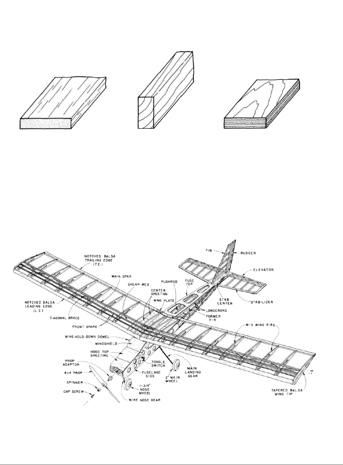
TYPES OF WOOD
BALSA BASSWOOD PLYWOOD
Study this perspective drawing to become familiar
with the parts of the PT-Electric.
5
Page 6
GET READY TO BUILD
D 1. Unroll the plan sheet. Re-roll it inside out to make
it lie flat. Note: The fuselage plan is printed on Side
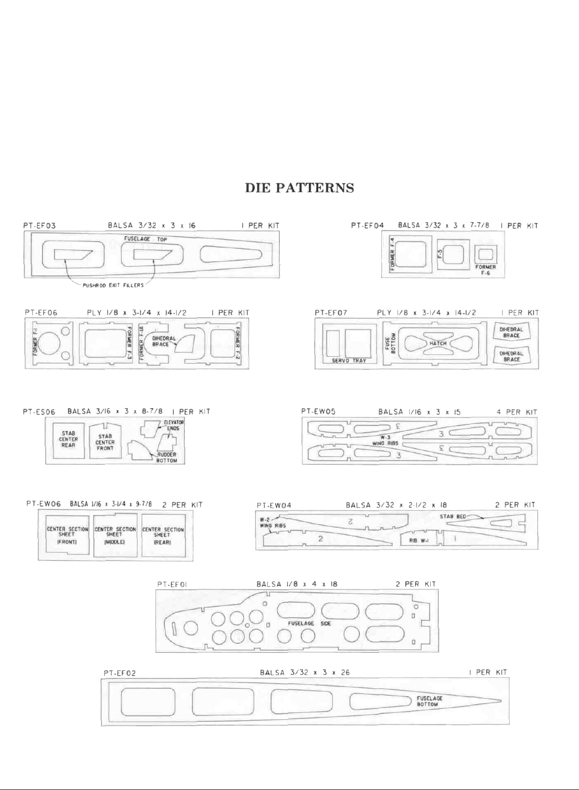
1 and the wing plan is printed on Side 2.
terns shown below to identify the die cut parts and
mark them before punching out. Save all scraps. If
any of the die-cut parts are difficult to punch out, do
not force them! Instead, first cut around the parts
with an Xacto knife.
D 2. Remove all parts from the box. As you do, figure
out the name of each part by comparing it with the
plans and the parts list. Using a felt tip pen, write
the part name or size on each piece to avoid confusion later. Be especially careful to identify the sticks
correctly, as there are several sticks having the same
width but differing thicknesses. Use the die cut pat-
NOTE: After punching out the die cut parts, use your
T-Bar or sanding block to lightly sand the edges to remove
any die-cutting irregularities.
D 3. As you identify and mark the parts, separate them
into groups, such as fuse (fuselage), wing, fin &
stab (stabilizer), and hardware.
6
Page 7
FUSELAGE
PREPARE THE LANDING GEAR PLATE
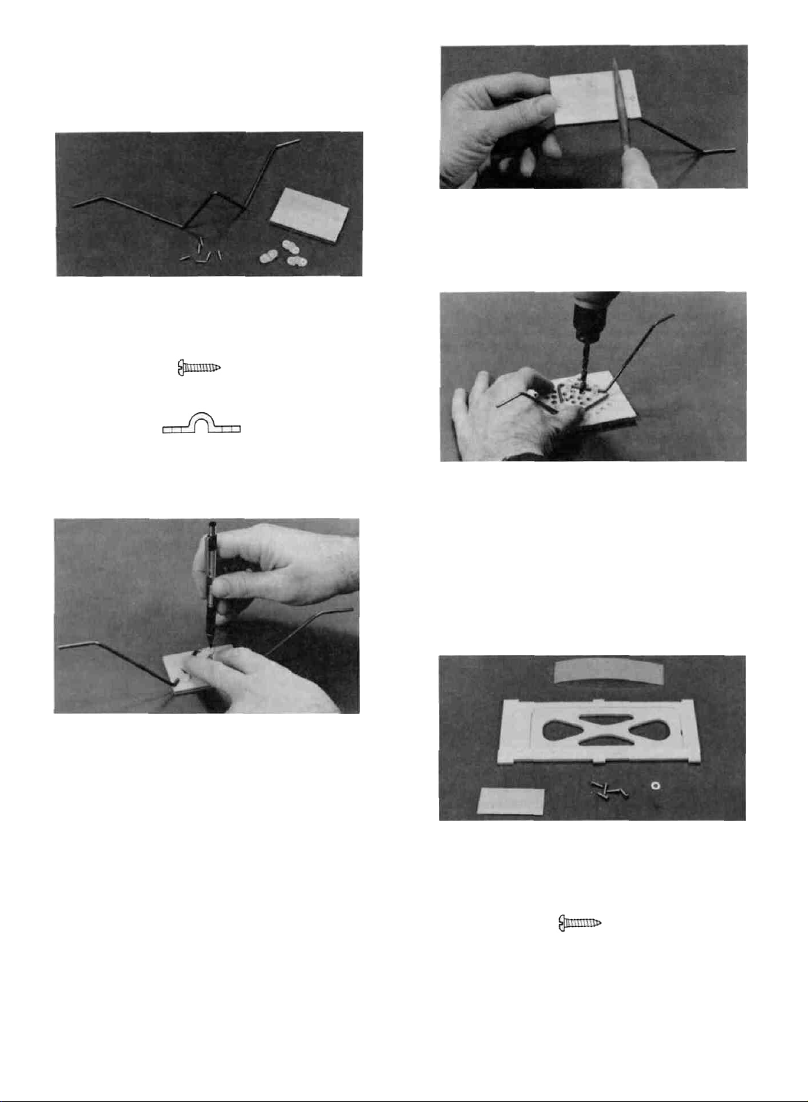
D 1. Find the following items: 3/16" x 1-27/32" x 2-3/4"
plywood landing gear plate, three nylon landing gear
brackets, six #2 x 3/8" screws, and the 1/8" wire
main landing gear.
#2x3/8" SCREW
LANDING GEAR STRAP
(NYLON)
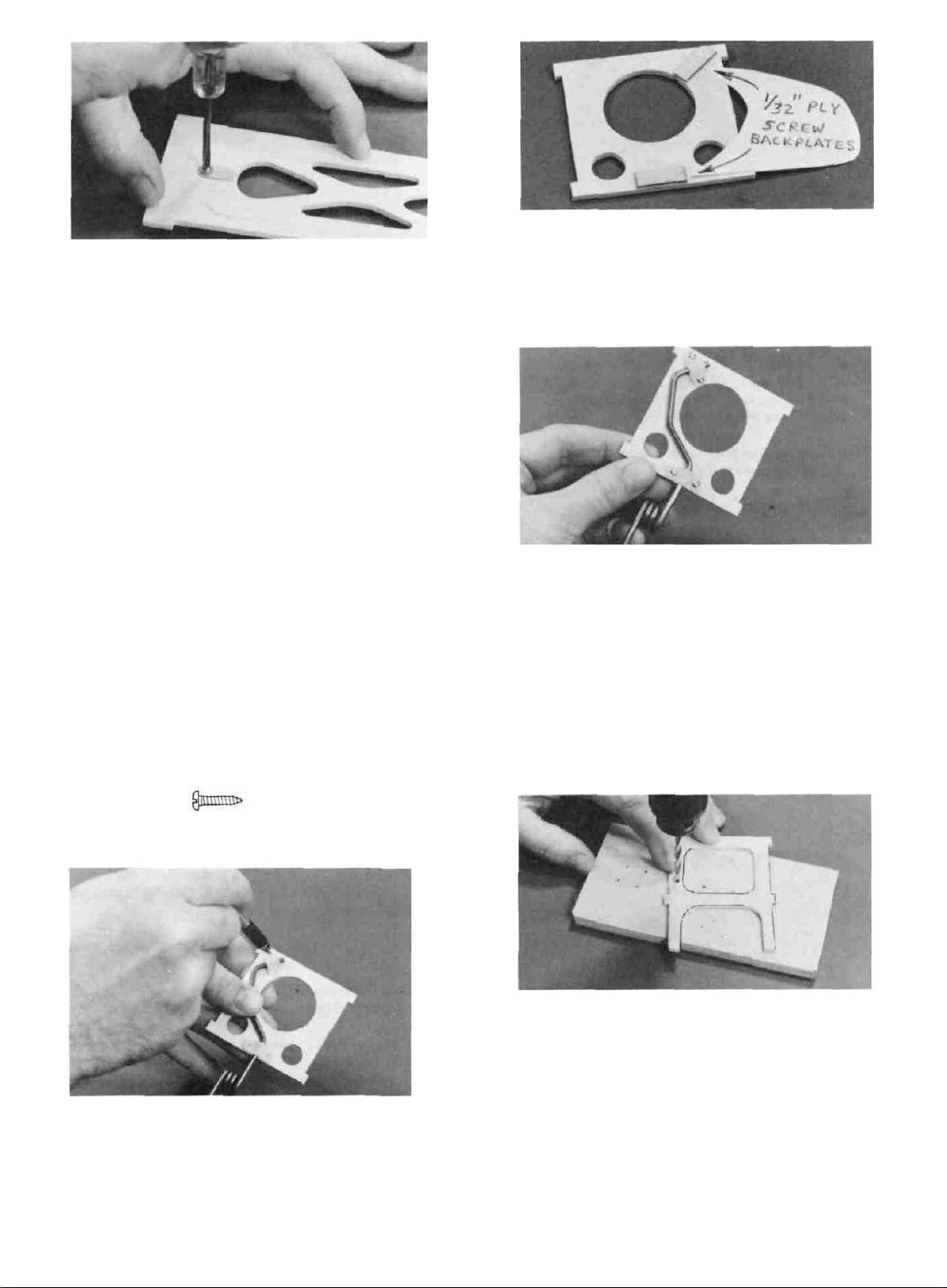
D 5. File the screws off flush with the surface of the
landing gear plate to prevent damage to the battery
pack.
D 6. Drill several 1/4" holes in the landing gear plate
as shown on the plan. These holes are for lightness,
and provide cooling air exit for the battery compart-
ment.
D 2. Hold the landing gear on the ply plate in the
position shown on the plan and put the nylon brac-
kets in place. While holding, use a pencil down
through the bracket holes to mark the screw hole
locations.
D 3. Drill 1/16" pilot holes at the above locations.
TIP: Anytime you drill a hole in wood, use a T-pin to start
the hole (for accuracy), and use a scrap wood backing underneath. This will prevent splitting out the back side of
the wood and will protect your work surface. The landing
gear screws will go in easier if you lightly scrape the screws
on a bar of soap to lubricate the threads.
D 4. Temporarily attach the landing gear to the ply
plate using the #2 x 3/8" screws and nylon straps.
D 7. Remove the landing gear and sand the ply plate
smooth. Set the 6 screws aside in a bag marked "LG
SCREWS".
PREPARE THE HATCH
D 1. Find the following items 4 length of hinge strip
material, Die-cut 1/8" ply fuse bottom and hatch,
1/32" x 1- 3/4" x 2" ply, five #2 x 3/8" screws, and
the #2 washer.
#2x3/8"
SCREW
7
Page 8
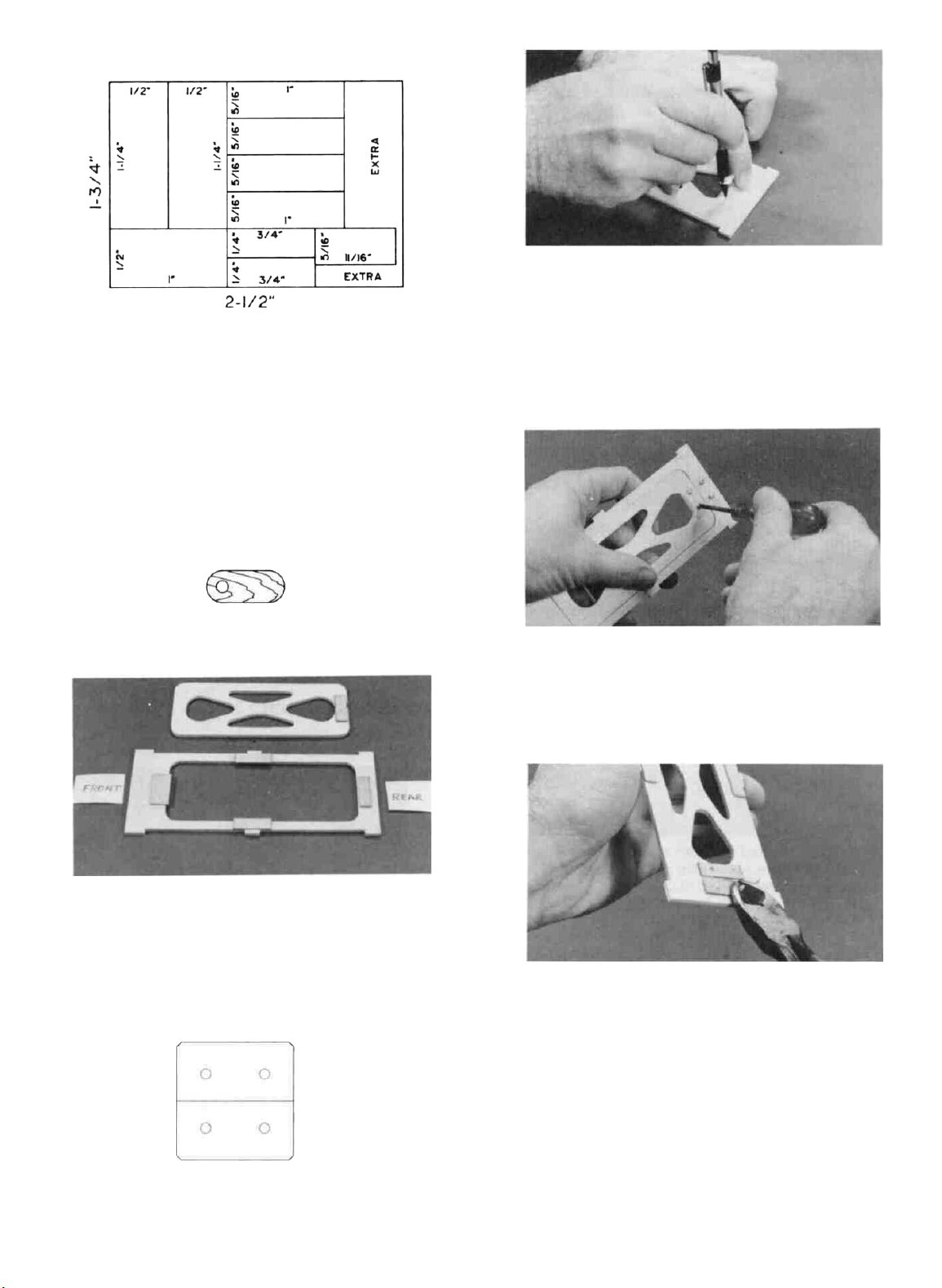
1/32" PLY CUTTING PATTERN
D 2. Using the pattern given here, mark the 1/32" x
1-3/4" x 2" ply plate for cutting. Cut out the small
pieces with a scissors or Xacto knife. The two 1-1/4"
x 1/2" pieces are the wing plates. Set them aside
until later. The two 1/4" x 3/4" pieces will be used
in the "PREPARE F-l" section.
D 3. From the 1/32" x 5/16" x 11/16" ply piece that you
previously cut, make the hatch locking tab according to the following sketch: (be sure to drill into a
wood backing to prevent splitting).
D 6. Lay the 1" hinge in place on the hatch and fuse
bottom, and mark the locations of the screw holes.
D 7. Drill 1/16" pilot holes at the marked locations.
HATCH LOCKING TAB
1/32 PLY
D 4. Using thin CA, Glue the remaining 1/32" ply pieces
to the 1/8" ply hatch and fuse bottom in the locations
shown on the plan. Note that the two side pieces and
the front piece extend 1/16" into the hatch opening.
D 5. Cut off a 1" length of hinge strip material and
drill four 3/32" holes as shown in the following
sketch.
D 8. Attach the hinge with four #2 x 3/8" screws.
D 9. Cut or file off the portion of the screws that would
protrude into the battery compartment. NOTE: Protect your eyes from flying metal when cutting off
screws.
HATCH HINGE
D 10. Drill a 1/16" pilot hole in the fuse bottom for the
hatch locking tab, at the location shown on the plan.
8
Page 9
D 11. Temporarily mount the 1/32" ply hatch locking
tab using a #22 x 3/8" screw and the #2 washer,
and cut off the portion of the screw that protrudes
into the battery compartment.
D 12. Check the operation of the hatch Sand the edges
of the hatch slightly to provide a close but non-binding fit.
D 13. Disassemble the above and set the hatch, hinge,
locking tab and screws aside until later.
PREPARE F- 1
NOTE: The PT-Electric has a "fixed" (non-steering) nose
gear which you will rigidly attach to Former F-l. At first
you may
the airplane on the ground with this setup We just want
to assure you at this time that it actually does steer quite
well' Because there is very little weight on the nose wheel,
the wind moving past the tail of the airplane enables the
rudder to turn the airplane almost as if the nose wheel
were steerable.
D 1. Find the die- cut 1/8" ply former F-l, two nylon
be
thinking
landing gear brackets, four #2 x 3/8" screws, the
1/8" wire nose gear, and the two 1/32" x 1/4" x 3/4"
ply pieces which you previously cut.
that
it
will
not be possible to
steer
D 4. Glue the 1/32" ply screw backplates to the back
of F-l, using the pilot holes you previously drilled
to determine where to locate the ply backplates.
D 5. Now re-drill the pilot holes.
D 6. Temporarily mount the nose gear to F-l using the
nylon brackets and screws.
D 7 Disassemble the above parts, and set the nose
gear, brackets and screws aside until later.
PREPARE F-2
D 1. Find the die cut ply former F-2.
D 2. From the detail drawing of F-2 determine the lo-
cation of the on-off switch pushrod.
#2x3/8"
D 2. Study the detail drawing of F-l on the plan, and
position the nose gear and nylon brackets While
holding them in place, mark the locations of the
screw holes.
D 3. Drill 1/16" pilot holes at the marked locations.
SCREW
D 3. Drill an 11/64" hole in F-2 at the above location.
PREPARE F-4 AND F-5
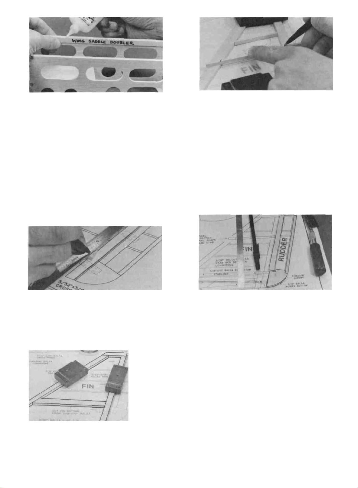
D 1. Find the die-cut 3/32" balsa formers F-4 and F-5,
and the two 3/32" x 3/8" x 17-7/8" balsa sticks
D 2. Cut a 9-1/8" length from each of the 3/32" x 3/8"
x 17-7/8" sticks, mark them "Wing Saddle Dou-
bler", and set them aside.
9
Page 10
D 3. From one of the remaining 3/32" x 3/8" balsa sticks,
cut cross-braces for F-4 and F-5. Glue these crossbraces to the formers with thin CA as shown on the
plan. Use only a few drops of glue to avoid excess
weight build-up.
MAKE THE FUSE SIDES
D 1. Find the 1/8" die- cut balsa fuse sides and the
1/8" x 3/8" x 23-7/8" balsa sticks. Inspect the balsa
sticks and pick out the four straightest ones which
you will use for the middle and lower longerons.
D 2. Tape the fuse plan to your flat work surface, then
tape a piece of waxed paper over the fuse side view.
D D 5. From one of the remaining short 1/8" x 3/8" sticks,
cut the tail post to match the plan.
D D 6. Hold or pin the parts accurately in place on the
plan, then glue the middle and lower longerons to
the fuse side and to the tail post using thin CA.
D D 7. Cut a third 1/8" x 3/8" balsa stick to match the
upper longeron on the plan (the upper longeron
extends back to the rear edge of F-6), and glue it to
the fuse side and to the middle longeron.
D D 3. Accurately position one of the 1/8" balsa fuse sides
on the plan and hold it firmly in place with a heavy
book or with "shot bags" (A handy shot bag can be
made by partially filling a sock with lead shot or
BB's).
D D 4. Lay the middle and lower "longerons" (1/8" x 3/8"
sticks) in place and draw a straight line at the front
of the tail post. Cut the longerons off at these lines
using a razor saw.
D 8. While the fuse side is still in place on the plan,
use a straightedge and a pen to mark the locations
of formers F-4, F-5 and F-6. (Skip this step when
building the second fuse side.)
D D 9. Sand the fuse side smooth using a T-bar sander
with 100 grit sandpaper.
D 10. Now repeat steps 3-7 and 9 to build another
identical fuse side.
D 11. Put the two fuse sides together and line them up
at the front and the bottom edges. Then check to
make sure they are exactly the same all the way
around. Sand the edges as necessary until the two
fuse sides match. It is especially important that the
overall length be the same, so sand the tail post as
necessary.
10
Page 11
D 12. Lay the two fuse sides flat on the table, with the
bottom edges touching. Then, using a straightedge
and a pen, extend the former location lines onto the
fuse side that does not have them.
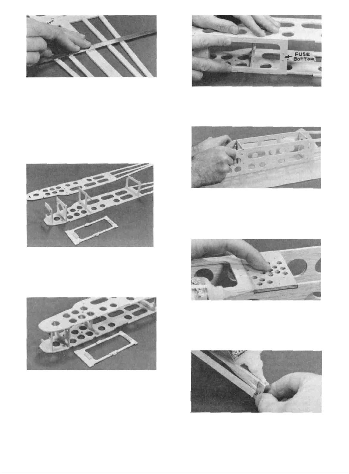
ASSEMBLE THE FUSELAGE
D 1. To begin, you'll need the following parts: The two
fuse sides you just built, Formers F-1A, F-l, F-2, F-3,
and the 1/8" ply fuse bottom.
D 2. Lay one of the fuse sides down flat on the table.
Insert the tabs of formers F-1A, F-l, F-2 and F-3 into
the slots in the fuse side. Check the plans and make
sure the formers are right side up. (Do not glue).
D 4. Press the 1/8" ply fuse bottom in place. Notice
that the interlocking parts automatically square-up
and align the front portion of the fuselage.
D 5. Lay a piece of waxed paper on your flat table, then
set the fuse assembly upright on the waxed paper.
Make sure that all tabs are fully seated into the
slots and notches. While holding the assembly to-
gether, apply thin CA glue to all joints.
D 3. Lay the left fuse side in place on the formers,
working the tabs into the notches. (Do not glue).
D 6. Turn the fuse upside down, and glue the 3/16" ply
landing gear plate in place in the notches in the
fuse sides (sand the ply plate, if necessary, for a good
fit). Add thick CA glue to the joint between the LG
plate and the 1/8" ply fuse bottom.
D 7. Turn the fuselage right side up, pull the tail posts
together, and apply thin CA glue to the tail posts.
11
Page 12
D 8. Now get the following parts together: Die-cut 3/32"
balsa fuse bottom, formers F-4, F-5 and F-6, and
the die-cut 3/32" balsa stab saddle.
D 9. Work the 3/32" balsa fuse bottom into place
between the bottom longerons. The front of the fuse
bottom must touch the rear of the landing gear plate.
With the fuse upright on a piece of waxed paper,
make sure the fuse bottom is even with the bottom edge of the fuse sides and bottom longerons,
then apply thin CA glue along the bottom joints,
pulling the bottom longerons together. Note: If you
have small hands and are unable to hold the stringers
together, you may use books or other square weights
to hold the longerons together.
D 12. Find the two die-cut 3/32" balsa pushrod exit
fillers, sand them to fit between the middle and lower
longerons just behind F-6. Glue them in place, flush
with the outside edge of the longerons.
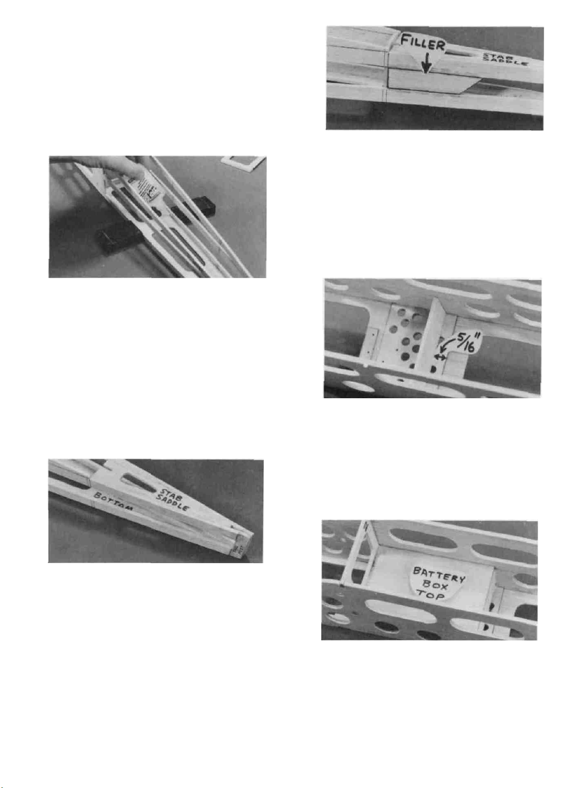
D 13. Find the 3/32" x 1-1/4" x 2-1/2" balsa battery
box rear, and glue it to the landing gear plate, 5/16"
forward of the rear edge of the landing gear plate.
D 10. Slide the 3/32" balsa stab saddle into place be-
tween the middle longerons. The front edge of the
stab saddle must line up with the marks you made
for the rear edge of F-6. Make sure the top edge
of the stab saddle is even with the top of the
longerons, and glue it in place with thin CA.
D 11. Install formers F-4, F-5 and F-6 at the locations
you previously marked. Note: you may have to sand
the
sides
of
the formers
the formers to the fuse bottom, then pull the longerons together and glue them to the formers.
slightly
for a good
fit.
Glue
D 14. Find the 3/32" x 2-1/2" x 4-1/16" balsa battery
box top. Position it so the bottom front edge is even
with the bottom edge the cross-brace on F-2. Glue it
to F-2, the fuse sides and to the battery box rear.
12
Page 13
D 15. Find the two 3/32" x 3/8" x 9-1/8" balsa sticks
which you previously marked "Wing Saddle Dou-
bler". Sand the ends of these pieces slightly, to fit
between F-2 and F-3. Glue these doublers in place
with the edge flush with the top edge of the fuse sides.
NOTE: This completes the fuselage assembly for now.
Leaving off the top sheeting will make it easier to install
the other components later.
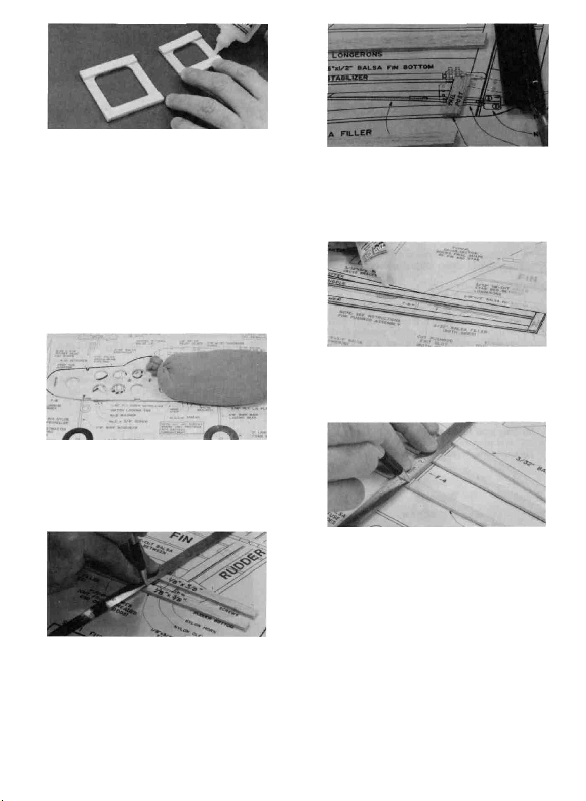
BUILD THE FIN
1. Find the following parts: 3/16" x 1/2" x 5-1/2" balsa
stick, five 3/16" x 3/8" x 24" balsa sticks, and a 3/32"
x 3/16" x 24" balsa stick. Select the straightest 3/16"
x 3/8" x 24" balsa stick and set it aside for later use
as the stabilizer trailing edge.
D 4. From the 3/32" x 3/16" x 24" balsa stick cut ribs
to fit between the framework, as shown on the plan.
Glue the ribs to the framework.
D 5. Sand both sides of the fin smooth using your T-bar
and 100 grit sandpaper. Sand the leading edge and
top of the fin to a rounded shape as shown in the
typical cross-section.
BUILD THE RUDDER
1. You'll need the following parts: Die-cut 3/16" balsa
D
rudder bottom, 3/16" x 3/8" x 24" balsa stick, 3/16"
x 3/16" x 24" balsa stick, and a 3/32" x 3/16" balsa
stick.
2. Working over the separate FIN drawing on the
D
plan, mark and cut the balsa sticks to make the
outer framework of the fin.Begin by laying one of
the sticks in place, then use a straightedge to mark
the cut-off lines. Cut the stick off with a razor saw,
then proceed to the next part.
3. Hold or pin the parts over the plan and glue the
D
outer framework pieces together with thin CA, working on waxed paper to prevent gluing to the plan.
13
2. In the same manner as the fin, cut the outer
D
framework pieces for the rudder.
3. Glue the outer framework and the rudder bottom
D
together with thin CA. Be sure to work on waxed
paper to avoid gluing the parts to the plan!
4. From the 3/32" x 3/16" balsa stick, cut ribs to fit
D
between the rudder leading edge and trailing edge.
Glue the ribs in place.
5. Sand both sides of the rudder smooth and flat.
D
Sand the upper rear corners of the rudder to a round
shape as shown on the plan. Sand the trailing edge
and rudder bottom to a rounded shape as shown in
the typical cross-section.
Page 14
D 6. Draw a centerline down the full length of the
rudder leading edge, then use your T-bar sander to
sand the leading edge to a "V" shape as shown in
the typical cross-section.
BUILD THE STABILIZER
D 3. From 3/16" x 3/8" balsa sticks, cut the outer
framework pieces and glue them together. Note:
The straightest 3/16" x 3/8" balsa stick should be
used for the trailing edge.
D 4. Cut the triangular corner braces from the 3/16"
x 5/8" x 7" balsa stick and glue them in place.
D 5. Cut the stabilizer ribs from the 3/32" x 3/16" balsa
sticks and glue them in place.
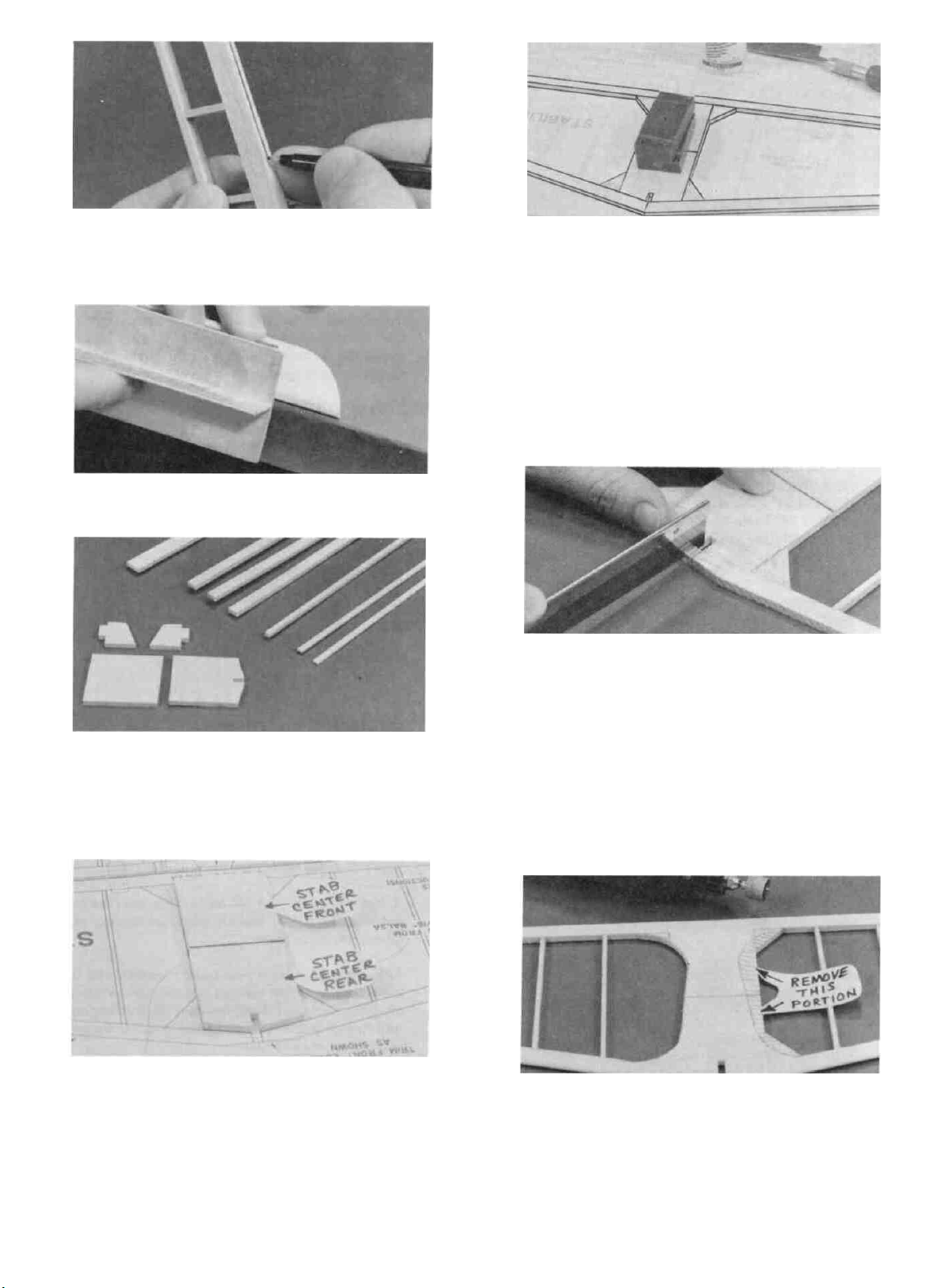
D 6. Cut out the fin notch in the leading edge, and trim
the front edge as shown on the plan.
D 1. Get the following items together: Die-cut 3/16"
balsa stab center front and stab center rear, 3/16"
x 3/8" x 24" balsa sticks, 3/32" x 3/16" x 24" balsa
sticks, and the 3/16" x 5/8" x 7" balsa stick. (Note:
The photo also shows the elevator parts).
2. Tape a piece of waxed paper over the separate
STABILIZER drawing on the plan, then lay the
die-cut 3/16" balsa stab center pieces on the plan
and pin in place. NOTE: These die-cut pieces may
have irregular edges, so you should sand the edges
with your T- bar first, until they fit the plan exactly.
Edge glue these stab center pieces together with thin
CA.
D 7. Sand both sides of the stabilizer smooth with your
T-bar, then sand the stabilizer leading edge and ends
to a rounded shape as shown in the typical cross-section.
NOTE: If the 3/16" balsa stab center pieces supplied in
your kit are soft balsa (easily dented with your fingernail),
do not perform the next step.
D 8. Now you may lighten the stabilizer by trimming
the stab center along the dashed line as shown on
the stabilizer drawing. Use your ruler to transfer
the trim lines from the plan to your stabilizer, then
use a Dremel Moto Tool sanding drum or a piece of
sandpaper wrapped around a dowel to sand away the
excess balsa.
14
Page 15

BUILD THE ELEVATORS
D 1. You'll need the following parts: Die-cut 3/16" balsa
elevator ends, 3/16" x 3/8" x 24" balsa stick, 3/16"
x 3/16" x 24" balsa stick, the remaining 3/32" x 3/16"
balsa stick, and the 3/32" wire elevator joiner.
ELEVATOR JOINER WIRE
D 7. Use a pin to start a pilot hole in the elevator
leading edge (on the centerline you previously
marked). The hole will be located in the middle of
the wire outline you drew in the above step. (See
photo).
D 2. Working on waxed paper over the plans, cut the
outer framework pieces and glue them together
and to the die- cut elevator ends.
D 3. Cut the elevator ribs from the 3/32" x 3/16" balsa
stick, and glue in place.
D 4. Sand both sides of the elevators smooth with your
T-bar, then sand the trailing edge and ends to a
rounded shape as shown in the typical cross-section.
D 5. Draw a centerline down the full length of the
elevator leading edge, then use your T-bar to sand
the leading edge to a "V-shape as shown on the
typical cross-section.
D 8. Drill a 7/64" diameter hole into the elevators at
the holes you started in the above step. (Drilling
slightly oversize will permit some adjustment when
joining the elevators).
D 9. Clean all oily residue from the wire elevator
joiner using a tissue dampened with alcohol or a
degreasing solvent. Then roughen the wire with
coarse sandpaper (so the glue will stick to the wire).
D 6. Position the elevators over the plans and lay the
3/32" wire elevator joiner on top of the elevators.
Then use a pen to mark the outline of the wire on
the elevators.
D 10. Use the threaded end of one of the 12" pushrod
wires to "file" a groove in the elevator leading edge.
Make the groove deep enough to fully accept the
joiner wire.
15
Page 16

D 11. Insert the joiner wire into both elevator halves,
then lay the assembly down on a piece of waxed
paper on a flat surface. Place a straightedge along
the leading edge of both elevators.
D 12. When you have the elevators lying flat on the
surface and both leading edges in a straight line,
apply thin CA glue where the joiner wire enters the
elevators and hold until the glue has set.
D 13. Inspect the assembly and apply thick CA to any
gaps around the joiner wire.
MAKE THE HINGES
D 1. You'll need the following: The remaining piece of
hinge strip material, a piece of 220 grit sandpaper,
a ruler, scissors and a 1/16" drill.
D 4. Drill four 1/16" holes in each of the hinge segments
as shown on the plan. Use a wood block as a back-
ing when drilling these holes. After drilling,
lightly sand the hinges again to remove any rough
edges caused by drilling.
D 5. Fold the hinge material back and forth a few
times to "condition" the hinges.
D 6. Cut the hinges apart with a scissors on the lines
you previously drew. Also snip off a small piece of
each corner.
D 2. Take the strip of hinge material and roughen both
sides with 220 grit sandpaper. This is best done with
a small piece of sandpaper held with your fingers,
rather than a sanding block. Do not sand the cen-
terline of the hinge material.
D 3. Using a ruler and a ball point pen, draw lines
dividing the hinge material into seven 3/8"-wide
segments.
HINGE
TEMPORARILY INSTALL HINGES (Do not glue the
hinges at this time).
D 1. You'll need the seven hinges you just made, plus
an Xacto knife with a No. 11 blade.
D 2. Draw an accurate centerline on the trailing edge
of the fin and stabilizer.
16
Page 17

D 3 Lay the fin and stabilizer on the plan and mark
the hinge locations on the trailing edges.
D 4 Now, while holding the elevators in place against
the stabilizer trailing edge, transfer the hinge locations over to the elevator leading edge Repeat this
process to mark the hinge locations on the rudder.
D 7 After you have cut about halfway into the wood,
you can push the blade all the way through, while
"wiggling" the knife handle back and forth Continue to pivot the knife while moving the blade to
both ends of the hinge location.
D 8 Trial fit the hinge into the slot If the hinge is
difficult to push in, re-insert the knife and move it
back and forth in the slot a few times to enlarge the
slot.
D 9 Repeat the above process to cut slots at all the
hinge locations in the fin, rudder, stabilizer and
elevators.
D 10 Assemble the rudder to the fin and the elevators
to the stabilizer (DO NOT GLUE), and check the
operation of the hinges
NOTE: The hinges supplied with this kit are thin enough
that they can be inserted into a slot made with an Xacto
knife Most other hinges require you to use a hinge slotting
tool The following steps describe how to easily cut the
hinge slots with an Xacto knife.
D 5. Begin by carefully cutting a very shallow slit in
the fin trailing edge at the hinge location This first
cut is to establish your cut in the right place, so
concentrate on staying on the centerline and don't
cut too deep!
D 6 Make three or four more cuts in the same line,
going slightly deeper each time As you make
these additional cuts, work on going straight into
the wood.
D 11 Cut off the portion of the bottom rudder hinge
that protrudes in front of the 3/16" x 3/8" fin trailing
edge Note: Be sure to use this hinge in the same
location later when making the final assembly
TEMPORARILY MOUNT CONTROL HORNS
D 1 You'll need Two nylon control horns, four 2-56
x 3/8" machine screws, a 3/32" drill and a small
screwdriver
2-56 SCREW
NYLON HORN AND NUT PLATE
17
Page 18

D 2 Use an Xacto knife to separate the nylon screw
backplates from the nylon horns.
D 7. Insert two 2-56 screws through the nylon horn
and through the holes you drilled Then screw them
into the nylon nutplate which originally came attached to the horn Tighten the screws until they
are snug, but do not crush the wood by over-
tightening.
D 8. Repeat the above process to install the nylon con-
trol horns on the elevator. NOTE: When marking
the locations for drilling, you must hold the
nylon horn on the BOTTOM of the elevator!
INSTALL SERVOS
D 3. Lay the rudder on the fuselage plan side view and
determine where the nylon control horn should be
located Holding one of the nylon horns in place on
the left side of the rudder, use a pencil to mark
through both holes in the horn
D 4. Remove the rudder from the fin, and remove the
hinges.
D
5.
Start
pilot
holes with a pin
then drill the holes with a 3/32" drill
D 6. Harden the balsa in the control horn area by
putting a drop of thin CA into each hole After the
glue has set, re-drill the holes and sand the surface
smooth.
at
the
marked
locations,
NOTE The following instructions and photos describe how
to install Futaba S-48 servos in your PT-Electnc If your
radio equipment is different from that shown in the photos,
you may have to use a slightly different method to mount
your servos properly Be sure to read the instruction
manual for your radio before beginning this section.
If you have difficulty with the radio installation, ask an
experienced model builder for assistance
Special Note: Most radio systems sold today have "servo
reversing switches" on the transmitter, which enable the
modeler to install the servos without first checking to
determine which direction the servos rotate After the installation has been completed, the modeler merely flips
the switches on the transmitter to make the servos rotate
in the desired direction Many of the older systems, however, do not have servo reversing instead they include
one or two "reverse" or "left-handed" servos which rotate
in a direction opposite that of the other servos When installing the servos of a system that does not have servo reversing, you must plan ahead to use the "reverse" servos
where they are needed.
D 1 Prepare the servos by installing the four rubber
grommets into each servo, then inserting the brass
eyelets up into the grommets.
D 2 Place the servos into the die-cut 1/8" plywood
servo tray provided, and position them so they are
not touching the sides of the openings Note: If you
have only two servos, they will be used for elevator
and rudder control only (no servo-activated on-off
switching)
18
Page 19

D 3. Holding the servos in place, use a pencil to mark
down through the brass eyelets onto the plywood.
Remove the servos and drill 1/16" holes at each of
the marks.
D 4. Study the plan to determine where the servo tray
goes. Glue the servo tray to the fuse sides and to
F-3 with thin CA. Then apply thick CA on top and
bottom of the tray to lock it in place.
D 2. Note that we have punched the locations of the
four screw holes in F-1B Drill 1/8" holes at these
four locations. Be sure to use a wood backing
when drilling to prevent damaging the part you are
drilling.
D 3. Mount F-1B onto the front of the motor with the
two M3 x 6 metric screws.
D 5. Now install the servos into the tray using the
screws provided with your radio.
INSTALL THE MOTOR AND SWITCH HARNESS
D 1. You'll need the following: Electric motor and
switch harness, die- cut 1/16" ply F-1B, two M3 x
6 (metric) screws, and two #4 x 1/2" screws.
M3x6
SCREW
#4x1/2"
SCREW
D 4. Drill two 5/64" holes in F- 1A at the punched
locations. (These are pilot holes for the #4 x 1/2"
mounting screws).
D 5. Insert all the switch harness components through
the large hole in F-l, then slide the motor into place.
Secure F-1B to F-1A with the two #4 x 1/2" screws.
19
Page 20

D 6. Remove the nut and the washers from the toggle
switch. Insert the threaded barrel of the toggle
switch through the 1/4" hole in the fuse side, then
secure it with a nut on the outside.
D NOTE: The toggle switch in the photo is shown
incorrectly. It should be rotated 180 degrees, as
it is shown on the plan, to operate correctly.
Correct operation of the toggle switch means
that pushing the switch forward is "on", and
pushing the switch backward is "off.
INSTALL ON-OFF SWITCH PUSHROD
(Not required for 2-channel operation)
NOTE: If you wish to fly the PT- Electric with a 2channel radio (rudder and elevator control only), just
wrap masking tape around the micro switch to hold
it in the "closed" position, and proceed to the next
section.
D 3. Insert the plastic outer pushrod sleeve through
the hole you previously drilled in F-2 and glue it
securely to F-2 with thin CA, followed by thick CA.
The tube should protrude only about 1/4" in front of
F-2.
D 4. Grasp the 1" threaded rod in the middle with a
pliers, and screw the nylon clevis onto one end and
the plastic pushrod onto the other end.
D 1. You'll need the following parts: 4-1/4" long plastic
outer pushrod sleeve, 6-3/8" long inner plastic
pushrod, 2-56 threaded rod 1" long, and a nylon
clevis.
NYLON CLEVIS
2-56 x I" THREADED ROD
D 2. Roughen the outside surface of the plastic pushrod
sleeve with 100 grit sandpaper (so the glue will stick
better).
D 5. Insert the plastic inner pushrod into the outer
sleeve and attach the nylon clevis to the servo arm.
(You may have to drill the servo arm with a 5/64"
drill bit to fit the clevis pin).
D 6. Temporarily hook up your radio system. (Be sure
to read the radio instruction manual regarding
proper hookup and battery charging procedures).
D 7. Study the fuse plan side view and note the position
of the micro switch. Now hold the micro switch
against the fuse side in this approximate position.
Operate the throttle servo and observe how the push
rod contacts the micro switch. Move the micro
switch around until the pushrod "clicks" the micro
switch only when the throttle stick is pushed almost
fully forward.
20
Page 21

D 8 When you have determined the correct position
for the micro switch, draw a line around the switch
on the fuselage side for reference.
D 9 Holding the micro switch in place, push a pin
through both holes in the micro switch and out
through the fuselage sides
D 10 Now drill two 3/32" holes through the fuselage
side at the pin holes Then mount the micro switch
with the two 2-56 x 5/8" screws and nuts
MOUNT THE RECEIVER SWITCH
D 1 Remove the face plate from your receiver switch
and hold it against the outside of the fuselage as
shown in the photo Make sure the switch will be
located above the battery box, and clear of the
on-off switch pushrod!
D 2 Mark the locations of the screw holes and the
rectangular switch hole, using the faceplate as a
guide
NOTE: Before proceeding, read " Peak Battery
Charging " in the appendix at the back of this book.
NOTE: Remove the propeller from the motor before
testing your electrical system in the next step!
D 11 When you have the motor and switch harness
installed, you may check its operation by hooking
up the motor battery* and activating the toggle
switch The motor should begin running when the
transmitter throttle stick is pushed forward to full
throttle, and stop when the stick is pulled back With
the toggle switch in the "off position, you should
not be able to turn the motor on with the throttle
stick In order for this safety feature to be effec-
tive, you should always keep the toggle switch
in the "off position until just before you are
ready to fly.
D 3. Drill 3/32" holes for the switch mounting screws.
D 4 Use an Xacto knife to cut out the rectangular
switch hole
D 5. Mount the switch to the fuse side and check the
operation (Pushing the switch toward the front
of the airplane is "on"),
CUT PUSHROD EXIT SLOTS
D 1 Study the plan and note the location of the elevator
and rudder pushrod exit slots(they are in the same
location on both sides of the fuselage) Using a ruler,
transfer the locations of these slots from the plan to
the fuselage, marking the front and rear of each slot.
*NOTE The motor battery must have a Kyosho-type connector to mate properly with the Thrustmaster switch harness If your battery connector is not compatible, you'll
have to change connectors
D 2 Drill 1/8" holes in the 3/32" balsa fillers at the
front and rear of the pushrod exit locations
21
Page 22

D 3. Use an Xacto knife to cut out the slots, between
the holes.
D 4. Sand the fuse sides smooth in the area of the push-
rod exit slots.
MOUNT THE STABILIZER
D 1. Sand the stab saddle area of the fuselage with
your T-bar to remove any excess glue.
D 2. Accurately measure and mark the exact center
of the top of former F-3 as a reference mark. Stick
a pin in at this point.
D 4. Line up the 3/16" notch in the front of the
stabilizer with the 3/16" notch in the stab saddle.
Tack glue the front of the stabilizer to F-6 with only
one drop of thin CA.
D 5. Measure from your reference mark in the center
of F-3 to both rear corners of the stab, and adjust
the position of the stab until the measurements are
equal. Holding the stab in this position, apply thin
CA to the stab/fuse joint at the rear of the stab. Also
add more CA at the back of F-6 to lock the stab in
place.
D 3. While holding the stab firmly in place onto the
saddle, measure down to the flat work surface from
both ends of the stab. If one side is higher than the
other, sand the high side of the stab saddle with your
T-bar sander and 100 grit sandpaper (Sand only a
little at a time!). Replace the stab in the saddle and
re-check the measurements. Continue this process
until the stab is level within 1/16".
D 6. Now turn the fuse upside down, and apply thin
CA glue all along the stab/fuse joints.
D 7. Temporarily attach the elevator to the stab with
the hinges.
TRIAL FIT THE FIN AND RUDDER
(Do not glue!!)
D 1. Temporarily attach the rudder to the fin with the
hinges (do not glue).
22
Page 23

D 2. Set the fin in place on the stab to check the fit
and alignment. If the fin TE does not match the fuse
tail post, you may sand a little off the lower front
corner of the fin LE to permit the fin to slide forward
until it contacts the tail post. Also, with the fin resting down on the stab, the bottom of the fin and rudder
must not protrude below the bottom of the fuse. If
they do, sand them off.
IMPORTANT NOTE: Improper fin alignment is one of
the most common causes of poor flying airplanes. The fin
absolutely must line up with the centerline of the
airplane! Therefore, use care in the following steps to
mount the fin properly.
MAKE THE PUSHRODS
D 1. You'll need the two 1/4" x 1/4" x 12-1/2" balsa
sticks, two 12" steel rods threaded on one end, two
nylon clevises and some strong thread (not included).
NYLON CLEVIS
STEEL PUSHROD WIRE
D 2. Clean the oily residue off the pushrod wires using
a tissue dampened with alcohol or degreaser.
D 3. Remember the mark you made in the center of
F-3? Now measure 3/32" left and right of that mark
and make two more reference marks. Now lay a
straightedge along the left side of the fin, with one
end of the straightedge on the left mark on F-3. Ad-
just the position of the fin until it matches the
straightedge.
D 4. Holding the fin in this position, draw lines on the
stab center on both sides of the fin for future reference. Double check this by laying the straightedge
along the right side of the fin and holding it on the
right mark on F- 3.
D 3. Draw a line 1-inch long on each end of both 1/4"
x 1/4" sticks as shown in the photo.
D 4. Use the threaded end of one of the wire pushrods
to "file" grooves in the balsa sticks where you drew
the lines. The depth of the grooves should be about
1/2 the thickness of the wire.
DO NOT glue the fin to the stab at this time!
D 5. Drill 5/64" holes through the sticks at the end of
the grooves you made in the above step.
23
Page 24

D 6. Screw a nylon clevis on the threaded end of both
steel pushrod wires. Screw it all the way on, until
the wire is visible inside the clevis (about 17 full
turns). Note: The wire will be easier to hold if you
grasp it with a pliers.
D 7. Lay the wires on the fuse plan (top view), and use
a pliers to bend the wires to match the drawings of
the elevator and rudder pushrods. Notice where the
wire makes a 90-degree bend and goes into the stick
and mark that location on the wire. Make this bend
now and cut off the excess wire.
D 10. Insert the wires into the holes and slots in the
1/4" x 1/4" balsa sticks, and glue in place with thin
CA.
D 8. Take the straight wires that you cut off, and make
a short 90-degree bend in one end of each of them.
D 9. Use sandpaper to roughen the four ends of the
wires that will be glued into the balsa sticks.
D 11. Use your T-bar to sand the ends of the balsa
pushrods to a rounded and somewhat pointed shape,
as shown on the plans and in the photos. This will
reduce the chance of the pushrod binding against
something inside the fuselage.
D 12. Wrap the ends of the pushrods with strong
thread, as shown on the plan, apply thick CA to the
threads and smooth it out with a piece of waxed
paper. Allow to harden.
24
Page 25

INSTALL PUSHRODS
D 1. Remove the nylon clevises from the pushrods.
D 2. Insert the pushrods, threaded end first, through
the openings in F-3, F-4, F-5 and F-6, then out
through the pushrod exit slots you previously cut.
Note: You may have to bend the wire slightly to
allow it to pass out through the exit slots. If so,
straighten the wire after it is out.
D 3. Screw the nylon clevises back onto the threaded
rods, then snap the clevises onto the nylon horns on
the rudder and elevator.
D 4. With the elevator, rudder and servos in the neutral
position, mark the front of the pushrod wires where
they cross the hole in the servo output wheels or
arms.
COMPLETING THE FUSELAGE
D 1. Remove the following items from the fuselage:
F-1B, Motor, Switch harness, receiver, radio switch,
radio battery, servos, pushrods, horns and hinges.
Note: If it seems strange to you to now remove these
items, please be assured that this will make it much
easier to perform the next steps, and it will be very
easy and fast to re-install these items later.
D 2. Carefully sand the top edges of F-3, F-4, F-5 and
F-6 until they are even with the top longerons, being
careful not to gouge into the upper longerons.
D 5. Remove the clevises and remove the pushrods from
the fuselage and make "Z"-bends* in the wires at
the marks you just made.
*NOTE: You can make a "Z"-Bend with a regular pliers
(practice on a scrap first), or you may use a special "Z"-bend
pliers (available through your hobby shop). There are a
couple of alternatives to making Z-bends which you may
want to consider: 1. Use a solder-on clevis on the servo
end of the pushrod or 2. Use a Dubro No. 121 E-Z Connec-
tor to attach the pushrod to the servo arm.
D 6. Cut off the excess wire.
D 3. Trial fit the die-cut 3 32" balsa fuse top. It fits
against the front of the stab, and extends forward to
the front edge of F-3. Glue the fuse top in place.
D 4. Find the 3 32" x 2-1/4" x 2-3'4" balsa windshield
and glue it to the fuse sides at the bottom front corners, using thin CA. Allow to harden.
25
Page 26

D 5. Bend the windshield around the curve of the fuse
sides and over the top of F-2. Glue the windshield
in place. Trim the windshield even with the rear
edge of F-2. NOTE: If the windshield is hard balsa,
it will bend easier if you first wet the top surface
with water or alcohol.
D 6. Sand the top of F-l to match the top edge of the
fuse sides.
D 7. From the 1/16" x 3" x 6" balsa sheet, cut two pieces
of cross-grain sheeting and glue them to the top
of the fuse in front of the windshield (this is called
the "hood top").
D 10. SAND, SAND, SAND! Using your T-bar sander
with 100 grit sandpaper, sand the top and bottom
corners of the fuselage to a rounded shape as shown
in the former detail drawings on the plan (do not
round the fuselage corners in the wing saddle area).
Sand the fuselage sides, top, and bottom until they
are very smooth.
D 8. Carve a rounded area in the front of the sheeting
to provide clearance for the motor.
D 9. Apply lightweight filler compound to all gaps,
gouges and rough areas of the fuselage, and allow
to
dry.
D 11. DO NOT OMIT THIS STEP! Accurately weigh
the following items on a postage scale: Fuselage,
hatch, fin, rudder, stab, elevator and pushrods. These
items should have a total weight of no more than 7
ounces. If they are heavier than 7 ounces, that
means the balsa in your kit is slightly harder and
heavier than normal, you have used too much glue,
or you have not done enough sanding. If so, you
should make every effort to lighten the structure by
doing more sanding and by enlarging the lightening
holes in the 1/8" balsa fuse sides.
26
Page 27

WING
NOTE The PT-Electnc wing is made to fit together without glue, so you can assemble all of the major parts and
check to make sure they are all lined up before applying
thin CA to the joints
D 1. Turn the plan over to side 2, which shows the
wing Tape the plan to your flat work surface so the
"Right Wing Panel" is facing you Cover the right
wing panel drawing with waxed paper (so you won't
glue the wing to the plan!).
D D 4 Pin one of the 3/16" x 3/16" x 28" hardwood spars
to the plan, with the right end of the spar lined up
with the tip (The excess spar length extends past
the wing centerline)
D 2 The shaped and notched wing leading edges
(LE) and trailing edges (TE) are fastened together by thin layers of balsa Separate them by
folding until the balsa breaks Sand away the excess
balsa that remains along the edges after breaking
them apart, using a T-bar with 100-gnt sandpaper.
NOTE: Save several of the thin little balsa scraps
which will be used in step 8.
D 3 Before using the L E and T E pieces, you must
determine which pieces are to be used for the right
wing panel Here's how
A- We have drawn red lines on the top of each piece
D D 5 Accurately position the three die-cut 1/16" balsa
center section sheets on the plan and pin them in
place Notice the pre-cut openings for the dihedral
braces Edge glue the two rear sheets together with
thin CA, and glue them to the spar.
D D 6. Put the two W-2 ribs and the eight W-3 ribs in
place on the spars (do not glue).
D D 7. Lay the trailing edge in place with the end lined
up with the outside edge of the tip rib on the drawing
(the excess length extends beyond the wing centerline), and work the ribs into the notches (do not
glue).
D D 8 Lay down some of the 1/32" balsa scraps from step
2 between the ribs at the L E (these will raise the
L.E. 1/32" off the table).
B- Notice that the pieces are notched on one end, but
not on the other The notched end goes toward the
wing tip, and the end without a notch goes toward the
center of the wing.
C- Take one of the L E pieces and lay it on the right
wing panel plan with the red line up If the notched end
is on the right side (at the tip) you have the correct L.E.
D- Do the same thing to determine which T E piece
to use.
D D 9 Lay the leading edge in place and line up the end
with the outside edge of the tip rib on the drawing
(the excess length extends beyond the wing centerline) Work the ribs into the notches REMEMBER:
The L E is 1/32" above the table, supported by the
balsa scraps.
27
Page 28

D D 10. Set the W-l rib in place (do not glue), then lay
the top spar in place.
D D 11. Set W-l at the proper angle, using the die-cut
1/8" ply dihedral gauge. NOTE: The edge of W-l
must line up with the wing centerline(which
should also be the edge of the 1/16" balsa bottom
sheeting).
D D 12. Make sure that the ribs are all down onto the
plan and fully inserted into the notches in the L.E.
and T.E. Also make sure that the spars are seated
snugly down into the notches in the ribs. Check all
parts for correct alignment (especially rib W-l),
then apply thin CA glue to all joints.
D D 15. Find the stack of 1/16" balsa shear webs. Cut
one of the webs to fit between the two W-2 ribs and
glue it to the back of the spars. Also glue webs to
the spars in the next three rib bays. (See the detail
drawing showing the webs and braces on the wing
plan).
D D 13. From the 5-1/2" length of 1/4" balsa triangle,
cut pieces to fit between the ribs in the first two rib
bays. Glue these pieces to the bottom sheeting and
the L.E. as shown on the plan and in the photo.
D D 14. Lay two of the 1/8" x 1/8" x 28" balsa sticks in
the front spar notches, with the ends of the sticks
flush with the outside edge of the tip rib. Make sure
the spars are fully down into the notches, then apply
thin CA to all joints.
D D 16. From one of the 1/16" x 1/4" x 18" balsa sticks,
cut diagonal braces and glue these braces to the
spars as shown on the detail drawing.
D D 17. Sand the leading edge, spars and trailing edge
even with the tip rib, using your T-bar sander.
28
Page 29

D D 18. Find the two tapered balsa pieces that are 9-1/8"
long. These are the wing tips. Glue one of these
tapered balsa wing tips to the tip rib (the narrow
edge of the tapered wing tip goes down).
D D 19. Carve and sand the wing tip to blend with the
tip rib. Sand the front and rear corners to a rounded
shape as shown on the plan. Also sand the top and
bottom edges to a slightly rounded shape.
D 22. On rib W-l, draw lines 1/8" in front and back of
the spars.
D 23. Working very carefully and slowly with a razor
saw, cut out 1/8" strips in W-l in front and back of
the spars. Do this in both wing panels to provide
openings for the dihedral braces. Note: It is OK if
the part of W-l between the spars is broken out.
D D 20. Using a razor saw, carefully cut off the leading
edge, spars and trailing edge flush with rib W-l.
Then sand smooth and flat using a T-bar.
D 21. Turn the plan around so the Left Wing Panel
drawing is facing you, and repeat steps 4 through
20 to build the left wing panel in the same manner.
D 24. Check the spars in the area you just cut out. If
any wood or glue remains attached to the spars, sand
it off with your T- bar.
Page 30

D 25 Working on a flat table, place the two wing panels
together at the center Block up both wing tips 3-1/2"
with stacks of books, then trial fit the die-cut 1/8"
ply dihedral braces at the center Enlarge the open-
ing in W-l and the bottom sheeting if necessary to
allow the dihedral braces to fit without forcing them
in.
PRACTICE THE NEXT STEP "DRY" BEFORE
ACTUALLY DOING IT!
D 26 Place waxed paper under the wing center joint,
then mix up a batch of epoxy (30-minute epoxy is
preferred here to give you more time), and apply it
to the dihedral braces and spars Slide the wing
panels together, clamp the dihedral braces to the
spars with clothespins, and wipe up the excess glue
with a tissue While you are waiting for the epoxy
to harden, apply thin CA along the joint where the
two W-l ribs come together Make sure the wing
panels remain undisturbed until the epoxy has
fully hardened.
D 27. After the epoxy has hardened, examine the center
joint and fill any gaps with balsa dust and CA glue.
D 28. Sand the center section and the entire wing
smooth with your T- bar sander NOTE: When sand-
ing the wing, you must be very careful not to change
the shape of the wing by accidentally sanding into
the wing ribs.
D 29 Find the two 1/32" x 1-1/4" x 1/2" plywood pieces
These are the wing plates which protect the trailing
edge from damage by the wing hold-down rubber
bands.
D 30 Working on the table edge, use a sanding block
to "feather" (taper) the edges of the wing plates
Feather three edges of each plate, leaving one long
edge square.
D 31 Make marks on the T E 1-inch each way from
the wing centerline
D 32 Put the wing plates in position on the T E The
edge of the plate that is not feathered goes to the
rear along the T E The 1-inch marks you made in
step 31 are where the plates begin
D 33 Apply thin CA glue around the edges, holding
the plates firmly in place until the glue sets.
D 34. DO NOT OMIT THIS STEP! Accurately weigh
the wing on a postage scale It should have a total
weight of no more than 5 ounces. If it is heavier
than 5 ounces, there is not much you can do other
than some light sanding of the leading and trailing
edges and the wing tips Do not sand the hardwood
spars, as this could weaken the wing Proceed to the
next section.
PREDICTING THE FINISHED FLYING WEIGHT
At this time you should try to accurately predict
what the final weight of your PT-Electnc will be Remember that you are shooting for a target weight of 48
ounces or less with a 6-cell 1200 mAh motor battery, and
50 ounces or less with a 7- cell 1200 mAh motor battery
If it looks like your airplane will be only 1 ounce overweight, don't worry about it, as you will probably be satisfied with the flight performance If, however, you predict
a final weight that will be 3 ounces or more overweight,
you should take another look at the components you will
be installing in your airplane (servos, battery, wheels), to
see where you can reduce weight. I'll talk more about this
later
Here is a sample weight computation:
Fuselage, etc (see p 26 step 11) 7.0 oz.
Wing 5.0
Wire landing gear and all hardware 2 0
6 #63 rubber bands 0.25
Wheels (lightweight) 1.5
Thrustmaster motor, harness, prop
and spinner 9.5
Receiver, switch, 3 standard servos, 225 mAh
receivel bdtteiy 8.75
6-cell 1200 mAh motor battery 11.5
Covering material 3 0
TOTAL 48.5 oz.
30
Page 31

COMPLETE THE STRUCTURE
TRIAL FIT THE WING IN THE SADDLE
D 1. Using your T-bar sander, sand the wing saddle
area to approximately the same angle as the wing.
MOUNT THE ELEVATOR
NOTE: This section requires that you begin covering
your airplane. Before doing so, please study the instructions that are provided with the covering material.
D 2. Use a sanding block to lightly sand the ends of
the 1/4" hardwood wing hold-down dowels to re-
move the sharp cut edges.
D 3. Insert these dowels into the holes in the fuselage
(do not glue). NOTE: If the dowels fit too tightly,
enlarge the holes with a 1/4" or 17/64" drill bit.
D 4. Lay the wing in the saddle and hold it down with
two #63 rubber bands* (provided). Check the fit
of the wing in the saddle. It should rest snugly and
evenly onto the saddle. If not, sand the saddle slightly
for a good fit. *NOTE: When actually flying your
PT-Electric, you must use SIX #63 rubber bands
for wing hold-down.
D 1. Cut a 3/4" x 18" strip of covering material (Top
Flite "Super Monokote" or similar). Iron this strip
to the stabilizer trailing edge, overlapping equally
onto the top and bottom of the stab.
D 2. Using an Xacto knife, slit the covering in the areas
of the hinge slots. NOTE: You can find the hinge
slots by holding the elevator against the stab T.E.
D 3. Now cover the entire elevator by covering the
bottom first, then the top.
D 5. Measure down from both wing tips to your flat
building surface. If the measurements differ by more
than 1/8", you must sand the wing saddle slightly
until the measurements are the same.
D 4. Insert the hinges into the slits in the stabilizer
trailing edge, and glue these hinges to the stab by
applying thin CA glue around the hinges. Wait a
few minutes, then grasp each hinge and pull to make
sure the glue has penetrated and bonded the hinge
to the wood.
31
Page 32

D 5 Slit the covering on the elevator in the areas of
the hinge slots NOTE: You can find the hinge slots
by holding the elevator against the stab T E and
marking the location of the hinges NOTE: For the
next step you'll need the following 30-mmute epoxy,
a plastic soda straw, rubbing alcohol and some tissues
D 6 Mix up a batch of 30-mmute epoxy Force some
epoxy up into a soda straw by pushing the straw into
the puddle of epoxy several times Pinch the end of
the soda straw and insert it approximately 1/16' into
one of the elevator hinge slots Squeeze the straw
to force epoxy into the hinge slot Repeat this process
to get epoxy into all of the elevator hinge slots, then
push the elevator onto the hinges Carefully wipe
away all excess epoxy with a tissue dampened with
alcohol Do not disturb the elevator until the epoxy
has
fully
hardened__
MOUNT THE FIN
D 1 Hold the fin in place on the stabilizer and line it
up with the marks you previously made Check to
make sure the fin is perpendicular to the stab, using
a draftsman's triangle or a carpenter's square Apply
a couple drops of thin CA to tack glue the fin in
place
D 2 Double check the fin alignment (it must line up
with the fuselage centerline), then apply thin CA
all along the fin/stab joint Also glue the bottom of
the fin TE to the fuselage tail post, and glue the
front of the fin L E to F-6
TRIAL FIT THE MOTOR BATTERY
D 1 Cut several pieces of 1/4" foam rubber and glue
them to the inside of the battery compartment in the
locations shown on the plan Don't forget the piece
of foam that goes on the hatch, as this is the piece
that holds the battery up in the compartment
D 2 Insert your 6 or 7 cell 1200 mAh motor battery
through the hatch opening and into the battery compartment to check the fit Add or remove foam rubber
as necessary for a good snug fit
COVERING
D 1 Preparation: Before covering, make a final
thorough check to make sure the entire model has
been sanded smooth The covering material probably
will not hide imperfections in your structure, so now
is the time to fix them Then vacuum the model dust
free, using a soft brush attachment on your vacuum
cleaner Finally vacuum your entire work area until
it is dust-free Remove the hatch, rudder, elevator,
hinges, radio, batteries, servos, pushrods, motor,
switch harness and landing gear from your model
D 2 Using Top Flite "Super Monokote" (we used
white and metallic blue on our prototypes) or any
other good quality covering film and following the
manufacturer's instructions, cover your model in the
following sequence
COVER THE FUSELAGE
D 1 Stab TE (previously done)
D 2 Elevator bottom (previously done)
D 3 Elevator top (previously done)
32
Page 33

D 4. 1/2" strips of covering at joint between bottom of
stab and fuse.
D 5. 1/2" strips at joint between stab and fin.
D 7. Use a pin to poke "vent holes" in the bottom rear
corners of the stab to allow air to escape when cover-
ing the top. (Also do this before shrinking the fin,
rudder and wing covering).
D 8. Stab top
D 9. Shrink the stab covering, top and bottom
D 10. Fin left side and T.E.
D 11. Fin right side (overlap around T.E.)
D 12. Shrink fin covering, both sides
D 6. Stab bottom
D 13. Hold rudder against fin and mark hinge locations
on fin. Slit covering at slots.
D 14. Rudder left side and L.E.
D 15. Rudder right side (overlap around L.E.)
D 16. Shrink rudder covering, both sides
D 17. Slit covering at rudder hinge locations
D 18. Hatch bottom
D 19. Fuse bottom
33
Page 34

D 20. Fuse sides
D 21. Fuse top behind wing
COVER THE WING
D 26. Wing tips
D 22. 1/2" strip at base of windshield
D 23. Windshield
D 24. Fuse top in front of windshield
D 27. Wing bottom left (overlap centerline 1/4")
D 28. Wing bottom right (overlap covering 1/2")
D 29. Wing top left (overlap centerline 1/2" and iron
covering to the side of rib W-l
D 30. Shrink covering on left wing panel, top and bot-
tom
25. Iron the covering down around all openings that
D
are to be cut out, then use a sharp Xacto knife to
carefully cut the covering from the following openings: Pushrod exit slots, Wing hold-down dowel holes,
Toggle switch hole. Landing gear plate air exit holes,
Landing gear mounting screw holes, Micro switch
mounting screw holes, Elevator and rudder control
horn mounting screw holes, and the Radio switch
and switch mounting screw holes.
D 31. Wing top right (overlap covering 1/4")
34
Page 35

D 32. Shrink covering on right wing panel, top and
bottom
ADD WASHOUT AT THE WING TIPS
SPECIAL NOTE: One important flying charac-
teristic of the PT-Electnc is its ability to recover "handsoff* from a steeply banked turn This is made possible by
building the wing with DIHEDRAL and WASHOUT
Washout is intentional and measured wing twist You will
add washout to each wingtip by twisting the wing panels
so the trailing edge will be higher than the leading
edge at both wing tips. Here's how to do it...
D 1 Place the wing on your workbench with half of
the wing extending off the edge Lay some magazines
(or a "shot bag" as shown in the photo) on the wing
near the center, to hold it down.
D 5 Depending on what type of covering you have used,
you may find that, in time, some of the washout may
disappear Check it after an hour and repeat the
above process if necessary Also, re-check it periodically before you go Hying, because THIS IS A VERY
IMPORTANT REASON FOR THE STABILITY
OF YOUR PT-ELECTRIC.
ADD TRIM
D 2 Now grasp the wing tip and twist it so the trailing
edge goes up and the leading edge goes down As you
twist you will notice ripples forming in the covering
While holding this twist, use a heat gun to "reshrink" the covering Heat both the top and bottom
When you let go of the tip, you will see that the wing
will retain some of the twist.
D 3 Place the twisted wing panel back on your flat
work surface While holding the center of the wing
down on the surface, measure how far the trailing
edge is raised at the tip.
D 4 You must continue twisting and re- shrinking
until the trailing edge is 1/2-inch off the surface at
both tips. As an aid in getting this height correct,
you may make a small wood block 1/2" high by gluing
together pieces of scrap wood Keep this block handy
while twisting and heating, to check your progress
D 1 Add trim using covering film or self-adhesive trim
material or decals NOTE: We recommend that you
keep your trim scheme as simple as possible for ease
of application and to avoid weight build-up.
D 2 You may paint F-l, F-1A, F-1B and the motor
compartment area with any kind of hobby enamel.
(On our prototype we used Testers flat blue enamel)
35
Page 36

FINAL ASSEMBLY
D 1 In the same manner as the elevator, install the
rudder hinges by first inserting them into the fin
trailing edge and applying thin CA glue NOTE:
Remember that you previously cut off part of the
bottom rudder hinge, so you must find that hinge
and use it in the right place
D 2 Force 30-minute epoxy into the rudder hinge slots
with a plastic soda straw, and push the rudder onto
the hinges Wipe away all excess epoxy with a tissue
dampened with alcohol
D 10 Route the receiver antenna along the right side
of the fuselage and out through a small hole drilled
through the fuselage top rear and through F-3
NOTE: The antenna hole must enter the radio compartment approximately 5/16" below the top of F-3
so the antenna will not be pinched by the wing T E.
(See the antenna drawing on the fuselage plan).
D 11 If your lightweight wheels are the foam type with
square edges, you may sand them to a rounded (more
streamlined) shape using a sanding block
D 12 Install the main wheels and nose wheel using
1/8" wheel collars (not supplied) on both sides of
each wheel A small drop of oil on each axle will help
the wheels turn freely
BALANCE YOUR MODEL
NOTE: This section if very important and must not
be omitted!
D 1 With the wing attached to the fuselage, all parts
of the model installed, including the 6 or 7-cell
motor battery, gently turn the model upside down
D 3 Re-install the servos and the radio switch
D 4 Wrap the 225 mAh receiver battery in foam rubber
and insert it into the area between the battery box
rear and the servos
D 5 Mount the receiver to the top of the battery box
in the location shown on the plan using the square
of double-sided foam tape (provided) Plug the
servo wires into the receiver (The rudder servo
must be plugged into the aileron channel for 2
or 3-channel operation).
D 6 Re-install the control horns, pushrods, main land-
ing gear and nose gear NOTE: To attach the elevator
and rudder pushrods to the servo wheel, remove the
servo wheel from the servo, drill a 5/64" hole in the
servo wheel if necessary, woik the Z-bend into the
hole in the servo wheel, then replace the servo wheel
onto the servo
D 7 Re-install the motor, switch harness and
aluminum prop hub (secure the hub by tightening
the 6-32 alien setscrew)
D 8 Apply 1/4" wide foam wing seating tape all around
the wing saddle area to protect the wing
D 9 Lay the wing in place on the wing saddle and
carefully center it side-to-side, holding it in place
with a couple of rubber bands Now check the alignment of the wing by measuring from the wing tips
to the fin TE The measurements should be the same,
within 1/16" If not adjust the position of the wing
in the saddle When you have the wing positioned
properly, secure it with a total of six #63 rubber
bands To help in aligning the wing in the future,
you may now make marks at the leading and trailing
edge at the center of the wing, and make corresponding marks on the top of the windshield and the front
of F-3 for future reference
D 2 Carefully measure 3 inches back from the LE of
the wing along both sides of the fuselage and mark
the location of the center of the balance range
(this point is approximately at the rear edge of the
spar) Now turn the model right side up
D 3 Lift the model with your index fingers at the marks
you made at the center of the balance range (or for
more precision you may use the eraser end of two
pencils for lifting) If the tail drops when you lift,
the model is "tail heavy" and you must add weight
to the nose to balance If the nose drops, it is "nose
heavy" and you must add weight to the tail to balance
NOTE: The forward limit of the balance range is 3/8"
forward of the center mark The aft limit of the balance
range is 3/8" aft of the center mark
NOTE: You should make your first flights with the model
balanced in the center of the Balance Range Later you
may want to experiment by shifting the balance toward
the forward or aft limit of the recommended range Moving
the balance forward results in a model that is more resistant to stalls and spins but also may act sluggish and
require more speed for takeoff and landing Moving the
balance aft makes the model more agile with a lighter and
snappier "feel" In any case, do not balance your model
outside the recommended range.
36
Page 37

FINAL HOOKUPS AND CHECKS TEST THE MOTOR OPERATION
D 1. Make sure the control surfaces move in the proper
direction as illustrated in the following sketch
THREE-CHANNEL SETUP
TRANSMITTER
STICK MOVEMENTS
CONTROL SURFACE
MOVEMENTS
ELEVATOR MOVES UP
RUDDER MOVES RIGHT
ELECTRIC MOTOR SWITCH OH
D 2. Adjust your pushrod hookups as necessary to pro-
vide the following control surface movements'".
Elevator = 3/16" up, 3/16" down
Rudder = 5/16" Lt., 5/16" Rt.
*NOTE: These control surface "throws" are approximate
and provide a good starting point for the first flights with
your PT-Electnc You may wish to adjust the throws
slightly to provide the smoothness or quickness that you
prefer.
D 3 "Break-in" your electric motor by running it with-
out the propeller for at least F2 hour This will
insure that the motor will provide full power for your
first flight, and will extend the overall life of the
motor.
D 1. Make sure the toggle switch is in the "off" position.
D 2. Make sure no one in the area is operating a radio
on your frequency, then turn on the transmitter and
receiver (in that order), and pull the throttle stick
back Check to make sure that the micro switch is
in the "off position Turn off the receiver and transmitter (in that order).
D 3. Open the hatch, insert the charged 6 or 7 cell
motor battery, and plug the battery connectors together. Close the hatch and lock it with the hatch
tab.
D 4. Position yourself behind the wing, and grasp the
airplane firmly.
D 5. Turn on the transmitter and receiver (in that
order).
D 6. Make sure that all bystanders are behind the
airplane
D 7. Make sure the transmitter throttle stick is pulled
back to the "off" position.
D 8. Switch the toggle switch to the "on" position. The
motor should not run at this time.
D 9 Advance the throttle stick forward to the "on" (or
full throttle) position This should cause the motor
to start, spinning the propeller at a high RPM.
The wind generated by the rotating propeller should
be blowing toward the rear, and the airplane should
be pulling forward.
D 10. Continue running the motor and notice how the
power continues to be nearly constant for about 4-1/2
to 5-1/2 minutes, after which there is a definite
noticeable drop in power The power then drops
rapidly until it reaches a point where there is very
little thrust pulling the airplane forward. At this
point the battery is almost fully discharged.
D 4. With the prop hub adaptor attached to the motor
shaft, slide the propeller onto the shaft of the prop
hub adaptor NOTE: Do not install the prop backwards' The rounded side of the prop blades must be
facing forward Insert the 6-32 socket head cap
screw through the aluminum spinner, and tighten
the cap screw securely with the alien wrench.
PRE-FLIGHT
CHARGE THE BATTERIES
Follow the radio battery charging procedures in
your radio instruction manual You should always charge
your transmitter and receiver batteries the night before
you go flying, and at other times as recommended by the
radio manufacturer Read the battery charging procedure
in the Appendix at the end of this book to familiarize
yourself with the procedure for charging the motor battery.
D 11 Pull the transmitter stick to the "off" position,
and turn off the toggle switch.
D 12. Turn off the receiver and the transmitter (in that
order).
D 13. Remove the battery from the airplane and allow
it to cool before recharging Also leave the hatch
removed for several minutes to allow the interior of
the airplane to cool
NOTE: Follow the above procedure for operation of
the system each time you fly!
FIND A SAFE PLACE TO FLY
The best place to fly your R/C model is an AMA
(Academy of Model Aeronautics) chartered club field Ask
your hobby shop dealer if there is such a club and ]oin
Club fields are set up for R/C flying which usually makes
your outing more enjoyable. The AMA can also tell you
37
Page 38

the name of a club in your area We recommend that you
join AMA and a local club so you can have a safe place to
fly and also have insurance to cover you in case of a flying
accident
If a club and its flying site are not available, you
need to find a large, area at least 6 miles away from any
other R/C airplane operation and also away from houses,
buildings and streets A schoolyard may look inviting but
it is too close to people, power lines and possible radio
interference
The electric motor and motor battery used in your
PT-Electnc is very powerful, and the spinning propeller has a lot of momentum, therefore, if you touch
the propeller while it is spinning it may inflict severe
bruises, cuts or abrasions Keep this in mind, respect
the motor and propeller for the damage it is capable
of, and take whatever precautions are necessary to
avoid injury Always disconnect and remove the
motor battery until you are ready to fly again, and
always make sure the switches are turned off
before connecting the battery.
GROUND CHECK THE MODEL
If you are not thoroughly familiar with the operation
of R/C models, ask an experienced modeler to check to see
that you have the radio installed correctly and that all the
control surfaces do what they are supposed to Read the
APPENDIX in the back of this book, and become familiar with the proper operation of the electric motor and
electrical system in your model Check to make sure all
screws remain tight, that the hinges are secure and that
the prop is on tight
RANGE CHECK YOUR RADIO
Wherever you do fly, you need to check the operation
of the radio every time you fly This means with the antenna down, and the receiver and transmitter on, you
should be able to walk 100* feet away from the model and
still have control Have someone help you Have them
stand by your model and while you work the controls, tell
you what the various control surfaces are doing If this
test is successful, then repeat the test with the electric
motor running. If the control surfaces are not acting correctly, do not fly Correct the problem first NOTE: It is
possible that the electric motor will cause interference to
your radio (some radios are more easily interfered with
than others) If this happens, you may try installing a 2nd
01 uF capacitor between the motor leads, then repeat the
range check with the motor running
AMA SAFETY CODE
Read and abide by the following Academy of Model
Aeronautics Official Safety Code
GENERAL
1 I will not fly my model aircraft in competition or in the
presence of spectators until it has been proven to be airworthy by having been previously successfully flight tested
2 I will not fly my model aircraft higher than approximately 400 feet within 3 miles of an airport without notifying the airport operator I will give right of way to, and
avoid flying in the proximity of full scale aircraft Where
necessary an observer shall be utilized to supervise flying
to avoid having models fly in the proximity of full scale
aircraft
3 Where established, I will abide by the safety rules for
the flying site I use, and I will not willfully and deliberately
fly my models in a careless, reckless and/or dangerous
manner
RADIO CONTROL
1 I will have completed a successful radio equipment
ground check before the first flight of a new or repaired
model
*This is a minimum distance Check the instruction manual for your radio system for the recommended range check
distance.
MOTOR SAFETY PRECAUTIONS
Note: Failure to follow these safety precautions will result
in severe injury to yourself and others
Get help from an experienced pilot when learning to
operate motors
Use safety glasses when starting or running motors
Do not run the motor in an area of loose gravel or
sand, the propeller may throw such material in your
face or eyes.
Keep your face and body as well as all spectators
away from the path of the propeller as you start and
run the motor
Keep items such as these away from the prop loose
clothing, shirt sleeves, ties, scarfs, long hair or loose
objects (pencils, screw drivers) that may fall out of
shirt or jacket pockets into the prop
2 I will not fly my model aircraft in the presence of spectators until I become a qualified flyer, unless assisted by
an experienced helper
3 I will perform my initial turn after takeoff away from
the pit, spectator and parking areas, and I will not thereafter perform maneuvers, flights of any sort or landing
approaches over a pit, spectator or parking area
FLYING
IMPORTANT Regardless who you are or
where you live, we strongly urge you to seek the assistance
of a competent, experienced R/C pilot to check your model
for airworthiness AND to teach you how to fly No matter
how stable or "forgiving" your model is, attempting to
learn to fly on your own is dangerous and may result in
serious or even fatal injury to yourself and others, and
total destruction of your model Therefore, find an instructor (even if it means driving a long distance) and fly only
under his or her guidance and supervision until you have
acquired the skill necessary for safe and fully controlled
operation of your model
38
Page 39

The instructor will usually tell you about flying rules
at the field The number one rule you should always adhere
to is Do not turn on your radio system before you
first check out what frequencies people are using at
the time. If you turn on your radio system while someone
is flying on the same frequency as your transmitter, you
will probably cause their airplane to crash' This is called
"shooting someone down" No one wants all their hard
work ruined because someone wasn't thinking and turned
on their transmitter at the wrong time Always remember
this rule.
The instructor will check the model over to make
sure all the screws are tight and that the prop is tight.
He/she will check hinges to see if they are securely glued.
The instructor therefore checks all parts of the model to
see if it is airworthy The instructor will recommend
changes to be made before the model is ready for flight.
roll it will start to turn left or right Make corrections with
the rudder to keep it rolling straight into the wind If it
veers way off heading, cut the throttle, bring the plane
back and try again
After the airplane has good speed, gently pull the
elevator stick back until the airplane breaks ground and
begins to fly (Here is where most beginners make their
first big mistake') Using the elevator stick, make the plane
climb gradually, while using the rudder to keep the plane
heading into the wind If you climb too steeply right
after takeoff (before the plane has good flying speed),
the wing will stall and the plane will drop sharply.
Continue to climb gradually, even through the first turn,
until the airplane reaches an altitude of 200 to 300 feet
above the ground, which will give you some "maneuvering
room" and time to make corrections in the event that you
make a mistake.
TRIM OUT THE MODEL
Trimming the model means that you have an experienced flier fly the model and make final adjustments to
the position of and amount of throw in the control surfaces
The distances for the control surface throws we gave you
previously are close to where they should be But you won't
really know until the plane is in the air Slight changes
may need to be made The experienced flier, usually an
instructor from a local club, will know what to change as
the model is flying The instructor will adjust the trim
levers on the radio transmitter to make the model fly
straight and level with the control sticks in neutral Then
when the plane is on the ground the instructor will adjust
the clevises at the rudder and elevator so the trim levers
can be moved back to neutral (As you become more experienced, you can trim out your new models yourself The
first flight for any new plane should be used to trim it
out) Trim changes may be needed anytime so keep checking to see how the control surfaces react to the stick movements
YOUR FIRST FLIGHTS
The ideal way to leam to fly is to use the "buddy
box" system The instructor has his (or her) transmitter
attached to yours by a trainer cord There is a switch on
the instructor's transmitter so he can control who is flying
the model If you get into trouble, the instructor can switch
the control back to him and get the model flying safely
again The instructor will take the plane up to a safe altitude and then let you take over to practice for 2 or 3
minutes Then the instructor can land the model for you
As you progress, you then learn to land the plane and take
it off by yourself and then to do a complete solo!
THE TAKEOFF (From a Hard-Surface Runway)
(Under the supervision of an experienced R/C pilot)
If you have followed all of the above instructions and
your instructor has inspected your model and trimmed it
out, you should now be ready for takeoff If you are flying
from a hard-surfaced runway, you may place the PT-Electnc on the runway heading into the wind. Turn on the
transmitter and receiver, and switch on the toggle switch
Standing behind the airplane, advance the throttle stick
all the way to start the motor As the airplane begins to
THE TAKEOFF (Hand-Launch Method)
(Under the supervision of an experienced R/C pilot.
Many people feel that "hand-launching" is the
easiest and best way to perform the takeoff with lightweight airplanes such as the PT-Electnc.
The proper hand launch method is as follows If you
have followed all of the above instructions and your instructor has inspected your model and trimmed it out, you
should now be ready for takeoff The person launching the
airplane should grasp the bottom of the fuselage just behind the landing gear and point the nose into the wind.
Turn on the transmitter and receiver, and switch on the
toggle switch Standing behind the airplane, advance the
throttle stick all the way forward to start the motor As
soon as the motor starts, the hand launcher should raise
the airplane above his head and run into the wind (it is
not necessary to run far or extremely fast) After several
39
Page 40

steps, the hand launcher will thrust the airplane forward,
being careful to keep the wings level, and release it to
fly Immediately after the launch it will be necessary to
make slight corrections with the elevator and rudder to
keep the airplane flying level and straight into the wind
Continue flying level until the airplane has good
speed, then gently pull the elevator stick back until the
airplane starts a gradual climb (Here is where most beginners make their first big mistake') Using the elevator
stick, make the plane climb gradually, while using the
rudder to keep the plane heading into the wind If you
climb too steeply right after takeoff (before the plane
has good flying speed), the wing will stall and the
plane will drop sharply. Continue to climb gradually,
even through the first turn, until the airplane reaches an
altitude of 200 to 300 feet above the ground, which will
give you some "maneuvering room" and time to make corrections in the event that you make a mistake
FLYING WITH 3 CHANNELS
If you are using three channels of control (rudder,
elevator and motor on/off), you may periodically cut off
the motor power and glide your airplane In doing so, you
will find that it is possible to extend the flight time by
several minutes, especially if you fly into a "thermal" (an
updraft of air caused by wind currents or by heated air
rising from a dark colored area) When flying with three
channels, we like to save some of the battery power for
the landing, just in case we misjudge the landing approach
and need a little extra power to get back to the runway,
or to make another "go-around".
FLYING WITH 2 CHANNELS
the training of an experienced R/C pilot until you have
developed confidence in your landing skills
Begin your landing approach by flying downwind at
an altitude of approximately 100 feet When the airplane
is approximately 300 feet past you, make the "final" 180degree turn and line up the airplane with the runway,
heading into the wind During the final turn, cut off the
motor power to begin the final descent toward the runway
Do not dive the airplane, as it will pick up too much
speed Instead, when you cut the power, the airplane will
assume a gradually descending glide You should concentrate mainly on using rudder control to keep the airplane
heading into the wind and toward the runway When the
airplane reaches an altitude of about 6 feet above the
ground, gently apply a little "up elevator" to make the
airplane fly level (be careful, as too much up elevator at
this point will cause the airplane to stall and drop sharply)
As you keep holding a slight amount of up elevator, the
airplane will slow down and slowly descend as it loses its
flying speed Let the airplane slowly approach the ground,
applying a little more up elevator just before touchdown
This may sound difficult and complicated, but rest
assured that after only a few flying sessions with an experienced R/C instructor these things will begin to come naturally to you
Good luck, and happy flying!
APPENDIX
PROPER CARE OF YOUR THRUSTMASTER
MOTOR
Don't forget to switch on your transmitter and
receiver before switching on the motor! If you are only
using two channels of control (rudder and elevator), you
will switch on the power with the toggle switch, takeoff,
and fly the entire flight with full power This method of
control works just fine, but we must caution you about the
landing Based on the ground testing you have done, you
should have a pretty good idea how long the motor will
run before it begins to lose power When flying, you should
gain plenty of altitude during the 2nd half of the flight
When the motor begins to lose power, you will no longer
be able to climb, but at that time the airplane will still be
flying too fast to make a safe landing But, if you have
plenty of altitude, the airplane will fly long enough after
it begins to lose power that the battery will be almost
completely discharged, allowing you to make a slow and
safe landing Remember: When flying with 2 channels
you must fly the airplane until the battery is almost completely discharged before attempting to land.
Remember, practice and practice You will have a
few setbacks, we all do when learning Just don't give up
and have fun while you learn Radio Control model
airplane flying is one of the most rewarding hobbies
around Itjust takes a little work and practice to get there
LANDING
Note: The landing is usually the most difficult aspect
of R/C flying For best results you should remain under
Break- in: To properly break in, run the motor with no
load (prop and prop hub removed) for at least 1/2 hour
when the motor is new, before using it in your airplane
Power source: A 6-cell, 7 2 volt, 1200 mAh battery pack
(with "Kyosho"-type connector) is recommended as the
ideal power source for good power and long motor life
However, for more power, you may use a 7-cell, 8 4 volt,
800 or 1200 mAh battery pack
Oiling: The bronze bearings are self lubricating, but you
may extend their life and improve motor performance by
applying a very small amount of light machine oil to the
points where the center shaft touches the bearings, after
each hour of running time Note A "drop" of oil is far too
much, so you should apply the oil with a toothpick Never
oil the inside of the motor.
Brushes: The Thrustmaster brushes (which transfer electricity to the commutator inside the motor) are maintenance free and will last a long time under normal use
You may inspect the brush wear by looking through the
vent holes on the sides of the motor When the brushes
wear out it is time to replace the motor Note The use of
a 7-cell battery pack will shorten the life of the brushes
If you notice that your motor has lost power, but the
brushes are still good, it may help to spray some motor
cleaner (such as "Reedy in a Can") on the brushes
40
Page 41

Heat: Using multiple battery packs to run the Thrustmaster in successive flights may cause the motor to become
excessively hot Therefore, we recommend a 10-minute
"cool-down" period between flights.
WHEN YOU BLOW A FUSE
The Thrustmaster switch harness uses a 20 amp automotive-type fuse Replacements may be purchased
through your hobby shop or at most auto supply stores
The fuse is designed to open the electrical circuit when an
overload or short circuit occurs, to protect the other components
If the propeller is stalled, such as by running into
long grass or by "nosing over", the motorJtfill draw a very
large electrical current, causing the fuse to "blow" (the
internal fuse wire melts off)
Any time you blow a fuse, turn off the switch, discon-
nect the battery, check the condition of the wire, switches
and other components, and replace if any are damaged
Then replace the fuse and check the operation of the system.
Here are several things you can (and should) do to
keep your airplane as light as possible Keep in mind that
every ounce you cut from the weight will result in a
significant improvement in the way your airplane will
fly.
Lighten the Structure: (If your airplane is overweight)
D 1. Reduce the weight of the wood structure by enlarg-
ing the lightening holes in the fuselage sides (A
Dremel Moto Tool with a sanding drum works great
for this, or use sandpaper wrapped around a dowel).
D 2 Cut out the portion of the stabilizer center section,
as shown on the plan
D 3 "Honeycomb" the 3/16" ply landing gear plate by
drilling several 1/4" diameter holes, as shown on the
plan.
D 4. If
the fin and stab structure are hard balsa, you
may sand at least 1/16" off the inside edges of the
Fin, Rudder, Stab, and Elevator Do not remove any
material from the fin and stab trailing edge pieces.
WARNINGS: Do not use a fuse rated higher than
20 amps, and never operate the system without a
safety fuse, because doing so could easily result in a
fire, causing property damage and personal injury!
HOW TO ACHIEVE THE BEST PERFORMANCE
FROM YOUR ELECTRIC-POWERED MODEL
Whether you are just starting to build your electricpowered airplane, or have already completed it, you will
benefit from the information that follows
Your objective should be to build your airplane in
such a way that it will fly as it was designed GREAT'
To insure that it does, please read the following comments
and suggestions very carefully, and follow as many of them
as
you can
WEIGHT
NOTE In order to get a handle on this subject of
weight, you'll have to be able to accurately weigh your
airplane at various stages of construction A bathroom
scale is definitely not suitable for this' If you do not have
access to a suitable scale, we suggest that you take the
airplane to your local post office and ask them to weigh it
for
you.
We know from experience that this airplane,
equipped with a stock Thrustmaster motor, will R 0 G
(takeofffrom a hard-surfaced runway) and fly realistically
with a fully-charged 6-cell battery pack - IF- the total
weight is under 50 ounces Heavier airplanes do not fly as
well At 56 ounces it may not R 0 G , and the climb rate
will be disappointing A PT-Electnc that weighs 50 ounces
or less will probably fly very well unless other factors are
introduced that reduce performance (see " Thrust" and
"Other Factors")
D 5 Before covering, be sure to sand the edges of the
fin, stab, rudder, elevator, wing tips and fuse corners
to a round shape Also sand the fuse sides and bottom
until they are very smooth, with no traces of the
original glue joints.
Use Lighter Equipment:
D 1 It is possible to end up with a 50 ounce airplane
while using "standard-size" servos But your task in
keeping the airplane light will be made much easier
by using "micro" servos For example, you will save
3.6 ounces by changing from Futaba S28 servos to
Futaba S33 servos!
D 2 We strongly urge you to use a 225 mAh radio
battery pack in your airplane, rather than the standard 500 or 550 mAh pack This will save a couple
more ounces
D 3 You can save a couple of ounces by using the light-
weight Dave Brown wheels If you are concerned
about the non-aerodynamic shape of the wheels, you
can easily sand these foam wheels to whatever shape
you desire This will make them even lighter and
more aerodynamic
D
4 Cover
ings, such as Black Baron Film, Econokote or Super
Monokote, etc Do not use a fabric-type covering
D 5 If you really got carried away with the glue bottle
and your airplane is "hopelessly overweight", consider using an 800 mAh motor battery, rather than
a 1200 mAh pack Although the flight time will be
reduced by a couple of minutes, the weight savings
will result in better performance In addition, if you
switch from a 6-cell 1200 mAh pack to a 7-cell 800
mAh pack it will result in a greatly improved climb
rate (with a reduction in motor run time).
your
model
with
one
of
the
film-type cover-
41
Page 42

THRUST
There are several factors that contribute to the way
an airplane flies, but the most important things you have
control of are WEIGHT and THRUST Here are some ways
you can insure maximum thrust.
Battery: A 7-cell 1200 mAh battery is 1 or 2 ounces heavier
than a 6-cell 1200 mAh battery, but the additional thrust
provided by a 7-cell battery more than offsets the increased
weight For best results with 6- cells, we recommend using
a battery pack that has matched cells, such as the Kyosho
6-cell 1200 mAh racing battery If you are not satisfied
with the performance of your airplane with the battery
you are using, you may either switch to a 7-cell pack, or
you may purchase a "7th cell" that plugs into your switch
harness in series with your existing 6-cell pack.
Propellers: The Thrustmaster electric motor was designed especially for powering airplanes by direct-drive.
It is well suited for this application because it turns a
relatively large (8x4 or 9x4) propeller at an RPM that
provides sufficient thrust for this airplane Because it has
a relatively low no-load RPM (compared with some car
motors), you will not benefit by using a smaller diameter
prop We have tested many props and have found the Gnsh
8x4 (nylon) to be about the best The Taipan 8x4 (nylon)
and the Zinger 8x4 (wood) are about equal to the Gnsh The
only prop we found to give slightly increased thrust is the
Top Flite 9x4 Super-M (wood).
D 2 You can monitor the voltage of your charging bat-
tery with a voltmeter Your charger may have sockets into which you may plug a voltmeter If not,
you may insert the probes from the voltmeter into
the rear of the battery plug, making contact with
the metal portions As your battery charges, the vol-
tage will gradually increase When the battery is
fully charged, the voltmeter will show a slight drop
in the battery voltage At this point your battery is
fully charged.
D 3 The third method of "peaking" your battery is by
checking its temperature As the battery charges
it will remain cool until it is almost fully charged.
When it reaches the fully charged state it will rapidly
build up heat You can feel this heat with your hand
As soon as the pack starts to noticeably warm up,
disconnect it from the charger Do not continue
charging until the pack is hot! Overcharging will
damage your battery pack and can result in a fire
or explosion
Exercise Your Batteries: A new battery pack should be
"cycled" for best results You should peak charge the battery, then discharge it almost completely by actually running your motor with the propeller attached Do this 3 or
4 times on the ground before actually flying Be sure you
remove the battery from the airplane between each cycle
and allow it to cool before recharging
Motor Break-in: Be sure to run your motor with no load
(prop removed) for at least 1/2 hour before using it in your
airplane Because of the special design of the brushes, your
Thrustmaster's performance will continue to improve dur-
ing the first couple hours of operation
Peak Battery Charging: A fully charged battery pack
will provide an initial "surge" of power during the first 15
to 30 seconds of the motor run, then the power curve stays
fairly level for the next several minutes If you do not
charge your battery fully it will not deliver that surge
necessary for a good takeoffand climb-out There are three
easy ways to "peak-charge" your battery pack:
CAUTION! Regardless of which method you use, you must
never charge the battery unattended. NiCad batteries
have enough power to start a fire' Some modelers have
burned down houses or burned family cars by leaving them
unattended' If you fully charge a battery, then forget you
have done so, then fully charge the battery again, this
will cause the battery to get extremely hot and may cause
a fire or explosion If the timer on your charger sticks, it
will charge too long causing the same results If the insu-
lation on your wiring is cracked or missing and the red
and black wires touch, shorting the battery, much heat
will be produced which could easily start a fire or explosion
Always follow the charging instructions included with
your battery and charger.
D 1. Use a "peak-detecting" battery charger This
type charger will automatically charge your battery
until it is fully charged Unfortunately, this type
charger is not yet available for use with AC current,
but it works very well when connected to a 12-volt
car battery
Switch Harness: The standard "Kyosho"-type battery
connectors supplied with your switch harness are normally
adequate for most installations However, if you are looking for maximum performance, you may want to consider
installing high-performance battery connectors, such as
"Sermos R/C Snap Connectors" Replacing all the standard
switch harness wire with ultra high performance wire,
such as Jomar 12 gauge (665 strand) wire will also provide
a slight increase in performance
OTHER FACTORS
There are several other things that can reduce per-
formance considerably Check for the following conditions
and correct as necessary.
D 1 Make sure there is plenty of clearance between
the front of the fuse sides and the propeller If the
prop is very close to the front end of the fuse sides,
it may rub slightly during operation (due to vibration), and this will reduce performance significantly.
D 2 Examine your propeller for irregularities caused
by the injection molding process Carefully remove
these imperfections with fine sandpaper.
D 3 Most nylon propellers balance quite well as they
come from the factory, but we have found several
that require balancing You can improve the performance of your Thrustmaster by balancing the
prop, using an inexpensive prop balancer available
at your local hobby shop
D 4 To takeoff from a hard-surfaced runway the wheels
of your airplane must spin freely, with very little
42
friction Check the wheels for possible binding when
Page 43

moved from side to side, and put a drop of oil on each
axle.
D 5. If you store your airplane resting on the wheels,
the wheels will develop "flat spots", which prevent
them from rolling smoothly While this may happen
with any wheels, it is especially a problem with the
lightweight foam wheels To avoid this problem, support the airplane in storage with a Robart "Super
Stand" or similar.
SUMMARY
While this may seem like a lot of "extra work" just
to make your airplane fly well, most of the things we have
listed here are just good common sense modeling proce-
dures If you use the above information as a guide to build
(or modify) your airplane, we are certain you will be very
well satisfied with the results.
SEE THE FULL LINE OF GREAT PLANES AIRPLANES
AT YOUR HOBBY DEALER.
WE HOPE YOU WILL SELECT ANOTHER "GREAT
PLANE" AS YOUR NEXT PROJECT. THANK YOU!
MOTOR VIBRATION
If the propeller is slightly out of
balance, it may cause the rear of the
motor to vibrate against former F-l,
resulting in a noisy airplane. To prevent this, cut a few narrow "wedges"
from balsa scrap and push them into
the gap between the motor and F-l, as
shown in the above drawing.
43
Page 44

 Loading...