

Page 1
WARRANTY
Great Planes Model Manufacturing Co.guarantees this kit to be free from defects in both material and workmanship
at the date of purchase.This warranty does not cover any component parts damaged by use or modification. In no case
shall Great Planes’ liability exceed the original cost of the purchased kit. Fur ther, Great Planes reserves the right
to change or modify this warranty without notice.
In that Great Planes has no control over the final assembly or material used for final assembly, no liability shall be
assumed nor accepted for any damage resulting from the use by the user of the final user-assembled product.By the act
of using the user-assembled product, the user accepts all resulting liability.
If the buyers are not prepared to accept the liability associated with the use of this product,they are advised
to return this kit immediately in new and unused condition to the place of purchase.
READ THROUGH THIS INSTRUCTION MANUAL
FIRST. IT CONTAINS IMPORTANT INSTRUCTIONS
AND WARNINGS CONCERNING THE ASSEMBLY
AND USE OF THIS MODEL.
FUNDP03 for GPMA0050 V1.1 Entire Contents © Copyright 2001
P.O.Box 788 Urbana, IL 61801 (217) 398-8970
productsupport@greatplanes.com
INSTRUCTION MANUAL
Printed In USA
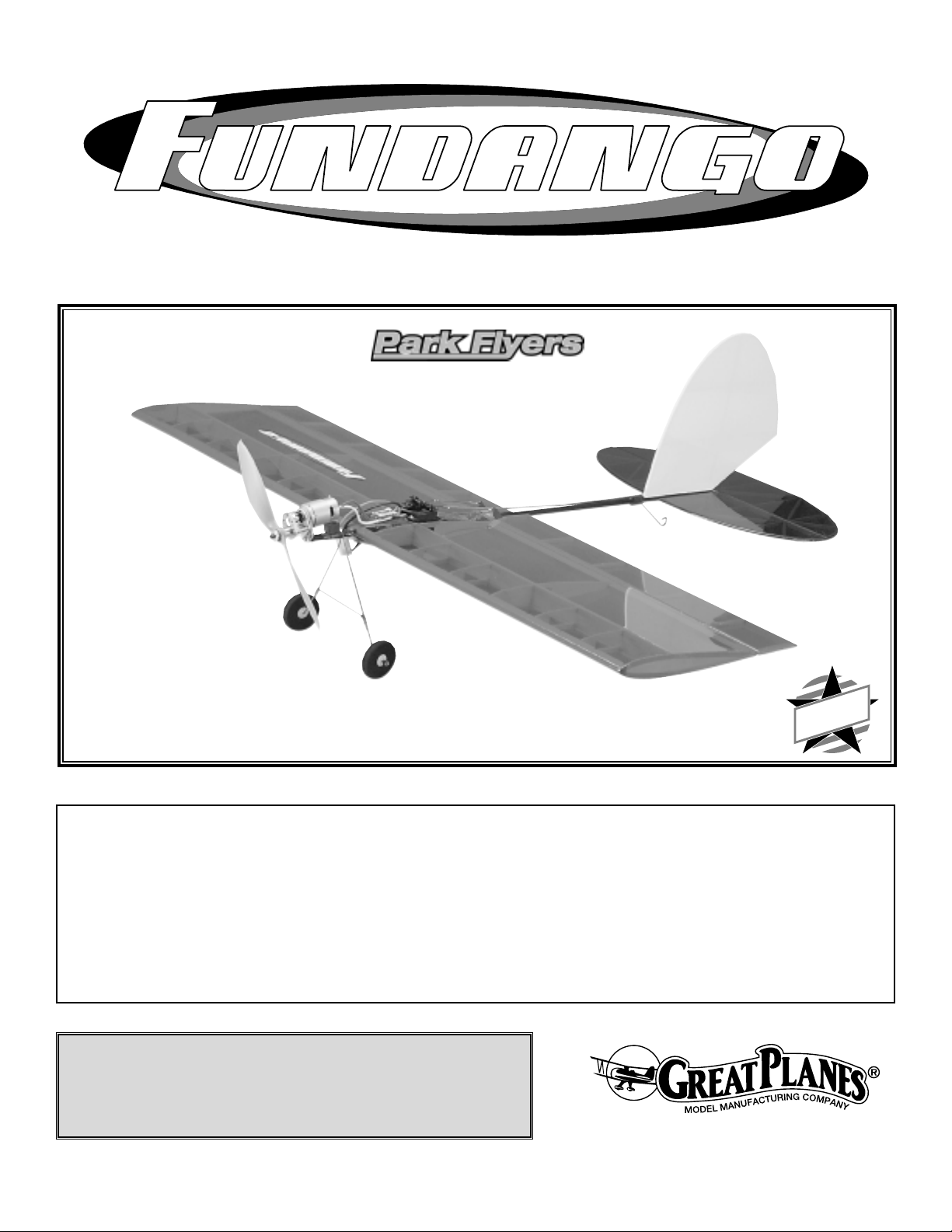
Wingspan: 35 in
Wing Area: 350 sq in
Weight (Ready to Fly): 13-16 oz
Wing Loading: 5.3-6.6 oz/sq ft
Fuselage Length: 30 in
TM
MADE IN
USA
Page 2

INTRODUCTION . . . . . . . . . . . . . . . . . . . . . . . . . . . . . . 2
SAFETY PRECAUTIONS. . . . . . . . . . . . . . . . . . . . . . . . 2
DECISIONS YOU MUST MAKE . . . . . . . . . . . . . . . . . . . 3
Radio Equipment. . . . . . . . . . . . . . . . . . . . . . . . . . . 3
Speed Control . . . . . . . . . . . . . . . . . . . . . . . . . . . . . 3
Motor System . . . . . . . . . . . . . . . . . . . . . . . . . . . . . 3
Battery Recommendation . . . . . . . . . . . . . . . . . . . . . 4
Battery Warning. . . . . . . . . . . . . . . . . . . . . . . . . . . . 4
Chargers . . . . . . . . . . . . . . . . . . . . . . . . . . . . . . . . . 4
Covering . . . . . . . . . . . . . . . . . . . . . . . . . . . . . . . . . 4
ADDITIONAL ITEMS REQUIRED . . . . . . . . . . . . . . . . . 4
Building Supplies. . . . . . . . . . . . . . . . . . . . . . . . . . . 4
Optional Supplies and Tools. . . . . . . . . . . . . . . . . . . 4
IMPORTANT BUILDING NOTES . . . . . . . . . . . . . . . . . . 5
Common Abbreviations . . . . . . . . . . . . . . . . . . . . . . 5
Types of Wood. . . . . . . . . . . . . . . . . . . . . . . . . . . . . 5
DIE-CUT PATTERNS . . . . . . . . . . . . . . . . . . . . . . . . . . . 6
GET READY TO BUILD . . . . . . . . . . . . . . . . . . . . . . . . . 7
BUILD THE WING . . . . . . . . . . . . . . . . . . . . . . . . . . . . . 7
BUILD THE AILERONS . . . . . . . . . . . . . . . . . . . . . . . . 10
BUILD THE TAIL SURFACES. . . . . . . . . . . . . . . . . . . . 10
Build the Fin . . . . . . . . . . . . . . . . . . . . . . . . . . . . . 10
Build the Stab and Elevator . . . . . . . . . . . . . . . . . . 12
BUILD THE FUSELAGE. . . . . . . . . . . . . . . . . . . . . . . . 13
Prepare the Fuselage Tube . . . . . . . . . . . . . . . . . . 13
Build the Landing Gear (optional). . . . . . . . . . . . . . 14
Mount the Landing Gear . . . . . . . . . . . . . . . . . . . . 15
COVER THE MODEL . . . . . . . . . . . . . . . . . . . . . . . . . . 16
Prepare the Model for Covering . . . . . . . . . . . . . . . 16
Cover the Wing and Ailerons . . . . . . . . . . . . . . . . . 16
Cover the Tail Surfaces . . . . . . . . . . . . . . . . . . . . . 16
FINAL ASSEMBLY . . . . . . . . . . . . . . . . . . . . . . . . . . . 17
Mount the Control Horns . . . . . . . . . . . . . . . . . . . . 17
Mount the Stab and Fin . . . . . . . . . . . . . . . . . . . . . 17
Mount the Battery . . . . . . . . . . . . . . . . . . . . . . . . . 17
Mount the Motor and Speed Control. . . . . . . . . . . . 18
Mount the Radio . . . . . . . . . . . . . . . . . . . . . . . . . . 19
PREPARE THE MODEL FOR FLYING . . . . . . . . . . . . . 21
Set the Control Throws. . . . . . . . . . . . . . . . . . . . . . 21
Balance the Model. . . . . . . . . . . . . . . . . . . . . . . . . 21
PREFLIGHT . . . . . . . . . . . . . . . . . . . . . . . . . . . . . . . . . 22
Charge the Batteries . . . . . . . . . . . . . . . . . . . . . . . 22
Identify Your Model . . . . . . . . . . . . . . . . . . . . . . . . . 22
Ground Inspection . . . . . . . . . . . . . . . . . . . . . . . . . 22
Range Check . . . . . . . . . . . . . . . . . . . . . . . . . . . . . 22
PERFORMANCE TIPS. . . . . . . . . . . . . . . . . . . . . . . . . 22
Cycle the Batteries. . . . . . . . . . . . . . . . . . . . . . . . . 22
Examine the Propeller . . . . . . . . . . . . . . . . . . . . . . 22
Motor Care . . . . . . . . . . . . . . . . . . . . . . . . . . . . . . 23
FIND A SAFE PLACE TO FLY . . . . . . . . . . . . . . . . . . . 23
MOTOR SAFETY PRECAUTIONS. . . . . . . . . . . . . . . . 23
AMA SAFETY CODE. . . . . . . . . . . . . . . . . . . . . . . . . . 23
FLYING. . . . . . . . . . . . . . . . . . . . . . . . . . . . . Back Cover
Takeoff. . . . . . . . . . . . . . . . . . . . . . . . . . . Back Cover
Flight . . . . . . . . . . . . . . . . . . . . . . . . . . . . Back Cover
Landing . . . . . . . . . . . . . . . . . . . . . . . . . . Back Cover
ROG Takeoff . . . . . . . . . . . . . . . . . . . . . . Back Cover
The Fundango is a fun to fly, aerobatic electric airplane that
can be flown in small spaces (see
Find a Safe Place to Fly
on page 23).Depending on your level of e xpertise, this plane
can either be a slow “Park Flyer” or an aerobatic model
capable of tight loops, inverted flight and fast rolls. Although
the Fundango uses only ailerons and elevator, with practice
you will be able to perform wing-overs and hammer-heads
which traditionally require a rudder.The Fundango was not
designed to look like a “real” airplane; instead it was
designed for exceptional aerobatic performance and we
think you'll agree that it meets this objective.
IMPORTANT: Though the Fundango is a small, lightweight
model that is capable of flying slowly, due to its aerobatic
design it is not intended for beginners.If you are new to R/C
airplanes, do not attempt to learn to fly with the Fundango.
You MUST learn to fly a trainer model first. Information about
R/C clubs and instructors is provided later in this manual.
1. Even though the Great Planes
Fundango
is a small,
lightweight model, if it is not assembled and operated correctly
it could possibly cause injury to yourself or spectators and
damage property.
2. Build the plane according to the plans and instr uctions. Do
not alter or modify the model, as doing so may result in an
unsafe or unflyab le model.In a few cases the instructions may
differ slightly from the photos. In those instances the plans
and written instructions should be considered as correct.
3.Take time to build straight, true and strong.
4. Use an R/C radio system that is in first-class condition. The
Fundango requires mini servos, a micro receiver and a micro
speed control that is capable of handling at least 15 amps.
5.You must properly install all R/C and other components so
that the model operates properly on the ground and in the air.
6. You must test the operation of the model before every
flight to insure that all equipment is operating and that the
model has remained structurally sound. Be sure to check
connectors often and replace them if they show signs of
wear or fatigue.
PRO TECT YOUR MODEL,Y OURSELF
& OTHERS...FOLLOW THESE
IMPORTANT SAFETY PRECAUTIONS
INTRODUCTION
TABLE OF CONTENTS
2
Page 3
Remember:Take your time and follow directions to end
up with a well-built model that is straight and true.
If you're an inexperienced modeler, we recommend that
you get assistance from an experienced,knowledgeable
modeler to help you with assembly and y our first flights.
You'll learn faster and avoid risking your model before y ou're
truly ready to solo. Your local hobby shop has information
about flying clubs in your area whose membership includes
qualified instructors.
You can also contact the national Academy of Model
Aeronautics (AMA), which has more than 2,500 chartered
clubs across the country. Through any one of them,
instructor training programs and insured newcomer training
are available. Contact the AMA at the address or toll-free
phone number below.
Academy of Model Aeronautics
5151 East Memorial Drive
Muncie, IN 47302-9252
Tele. (800) 435-9262
Fax (765) 741-0057
or via the Internet at http://www.modelaircraft.org
Before starting to build, compare the parts in this kit
with the Parts List and note any missing parts. Also
inspect all parts to make sure they are of acceptable
quality. If any parts are missing, broken or defective, or
if you have any questions about building or flying this
airplane, please call us at (217)398-8970 or e-mail us at:
productsupport@greatplanes.com.
If you are contacting us for replacement parts,please be
sure to provide the full kit name (Fundango) and the
part numbers as listed in the Parts List.
For the latest Fundango updates, you can also check
our web site at:
www.greatplanes.com
This is a list of items required to finish the Fundango that
must be purchased separately. For some of these items
there is more than one option which may require some
decision making ahead of time. Order numbers (in
parentheses) are provided for your convenience.
The Fundango requires three mini servos and a micro receiver .
Futaba®S3101 (FUTM0033) or Hobbico®CS-35 (HCAM0120)
micro servos and Hitec's®Feather Receiver (HRCL1535) are
suitable. The Feather Receiver comes without a receiver
crystal, so the crystal must be purchased separately.The order
number for the Hitec receiver crystal is HRCL23**. Substitute
the “**”with the channel number you require.For example, if the
transmitter you plan to fly your Fundango with is on channel 44,
order receiver crystal HRCL2344.
An electronic speed control with BEC (Battery Eliminator
Circuitry) is required.The BEC allows both the motor and the
radio system to be powered by the same battery (thus
eliminating an additional battery typically required to power
the radio).The Great Planes ElectriFly™C-20 High Frequency
Electronic Speed Control (GPMM2020) is recommended for
the Fundango. If you purchase the complete motor and gear
drive system, the speed control is included (refer to the
“Motor System” section that follows).
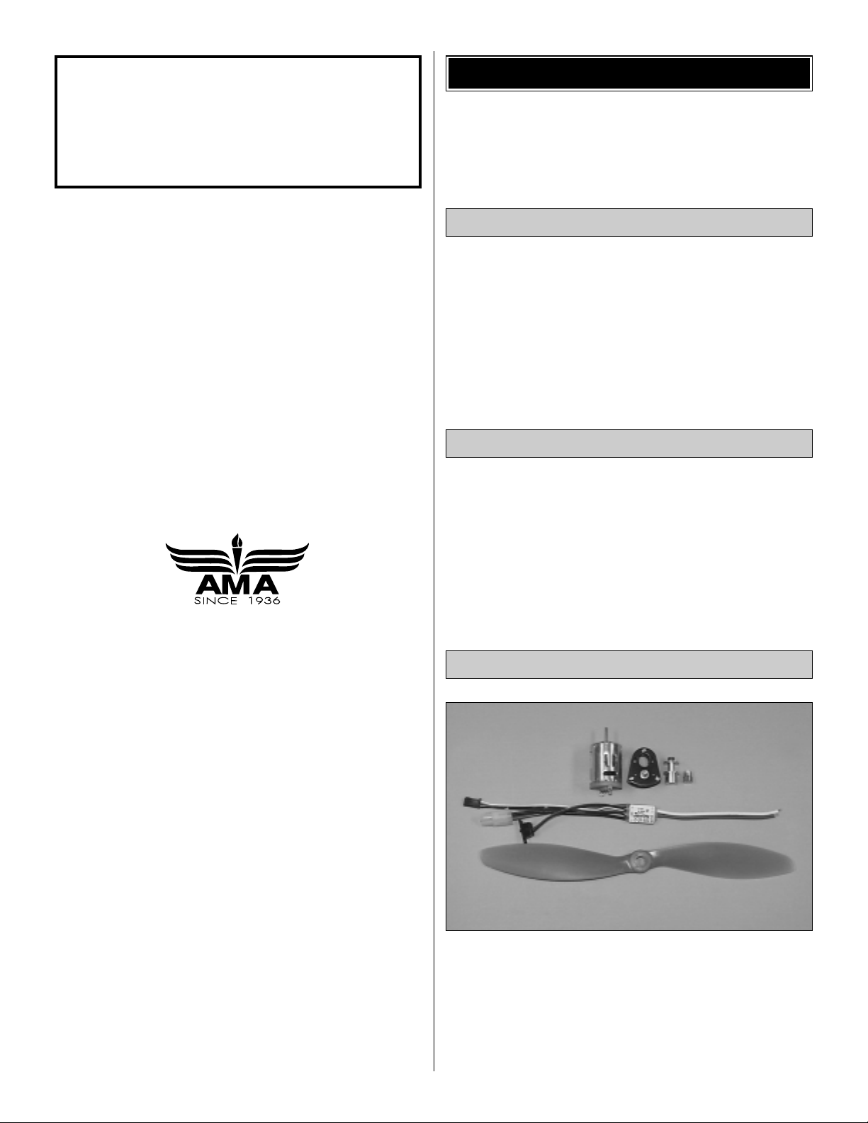
The Fundango is designed to use the Great Planes
ElectriFly T-400GD ESC motor system and gear drive for
electric flight (GPMG0400). This system includes a T-400
Ferrite Motor, S-400 3:1 ratio gearbox, 3mm prop adapter,
APC 10 x 7 propeller and the ElectriFly C-20 High
Frequency Electronic Speed Control w/BEC. The same
components are also available without the speed control by
ordering number GPMG0415.
Motor System
Speed Control
Radio Equipment
DECISIONS YOU MUST MAKE
Note: We, as the kit manufacturer, provide you with a
top quality kit and great instructions, but ultimately the
quality and flyability of your finished model depends on
how you build it; therefore, we cannot in any way
guarantee the performance of your completed model and
no representations are expressed or implied as to the
performance or safety of your completed model.
3
Page 4
4
Each individual Nicd or Nimh cell that makes up a battery is
1.2 volts. An 8-cell battery pack is 9.6 volts. Batteries are
also rated by their capacity in mAh (milli-Amp-hours), or how
much energy they store. A 600 mAh battery can supply 1
Ampere
for .6 hours (about 36 minutes).A 1200 mAh battery
pack has twice the capacity of a 600 mAh battery pack.
The battery pack recommended for the Fundango is the 8cell (9.6 volt) 600 mAh NiCd pack (HCAP6000).A 300 mAh
charger is included with the battery. If you already have a
charger, or if extra battery packs are required, the battery is
available separately (HCAP6005).
Do not attempt to fly the Fundango with 1200 mAh “sub-C”
battery packs, as they are too heavy.
ATTENTION: The product you have purchased is powered
by a rechargeable battery. At the end of its useful life, under
various state and local laws, it may be illegal to dispose of
this battery into the municipal waste system. Check with
your local solid waste officials for details in your area for
recycling options or proper disposal.
This product contains a chemical known to the State of
California to cause cancer and birth defects or other
reproductive harm.
The best type of charger to use is a peak charger, because
it charges the batteries until they are fully charged, then
automatically switches to a trickle charge mode. The
Hobbico Accu-Cycle™Plus (HCAP0270) is suitable for peakcharging the battery pack recommended.
The batteries may also be peak-charged by using a volt
meter to monitor the voltage while the batteries charge.The
voltage increases as the batteries charge.When the voltage
begins to decrease the batteries are fully charged (“peaked”).
The 9.6 volt 600 mAh battery recommended for the
Fundango may be charged at a rate no higher than 400
mAh. At this rate, it will take 90 minutes to charge a
discharged battery. If the battery is not discharged (and you
are not using a peak-charger), connect the battery to the
motor on your model. Run the motor until the propeller is
turning slowly, thus discharging the battery.
IMPORTANT: While charging, monitor the temperature of the
battery frequently .If the battery becomes warm, disconnect it
from the charger.
Though the Fundango is a small, lightweight model, it isn't a
floater, so using ultra-light coverings isn't a necessity. Some
weight can be saved by using Top Flite®EconoKote®or
Coverite™Micafilm™, but the overall savings is minimal and
has no noticeable effect on the way the Fundango performs.
Our prototypes covered with Top Flite MonoKote®film
performed very well.
In addition to the equipment listed in the “Decisions You
Must Make” section, following is the “short list” of the most
important building supplies required to build the Fundango.
We recommend Great Planes Pro™CA and Epoxy glue.
❏ 1/2 oz.Thin Pro CA (GPMR6001)
❏ 1/2 oz. Medium Pro CA+ (GPMR6007)
❏ Hobby knife (HCAR0105)
❏ #11 blades (HCAR0211)
❏ Single-edge razor blades (HCAR0212)
❏ Soldering Iron (HCAR0776)
❏ 60/40 Resin core solder (or other solder suitable for
electrical use)
❏ Approximately 3' of light string
❏ Small T-pins (HCAR5100)
❏ Builder's triangle (HCAR0480)
❏ Electric drill and drill bits: 1/16" [1.6mm], 5/64" [2mm] (or
1/16" [1.6mm]), 3/32" [2.4mm], 1/8" [3.2 mm], 5/16"
[7.9mm], #60 (.040") [1mm]
❏ Small Phillips and flat blade screwdrivers
❏ Pliers with wire cutter (HCAR0630)
❏ Great Planes Plan Protector (GPMR6167) or wax paper
❏ Sanding tools and sandpaper assortment
❏ Sealing Iron (TOPR2100)
❏ 70% Isopropyl rubbing alcohol (or water for bending
balsa sticks)
Here is a list of optional tools that may help you build
the Fundango.
❏T op Flite Precision Magnetic Prop Balancer™(TOPQ5700)
❏ Top Flite Hot Sock™iron cover (TOPR2175)
❏ Straightedge with scale (HCAR0475)
❏ Cutting mat (HCAR0456)
Optional Supplies and Tools
Building Supplies
ADDITIONAL ITEMS REQUIRED
Covering
Chargers
Battery Warning
Battery Recommendation
Page 5
❏ Masking Tape (TOPR8018)
❏ CA Debonder (GPMR6039)
❏ CA Applicator tips (GPMR6033)
❏ Great Planes 5-1/2" [140mm] Bar Sander (GPMR6169)
and 150-grit adhesive back sandpaper (GPMR6183)
❏ Top Flite 320-grit sandpaper (TOPR8030) and 400-grit
sandpaper (TOPR8032)
❏ Razor saw or Dremel®tool with cut-off wheel
❏ Medium T-Pins (HCAR5150)
For the best performance, the Fundango must be built light.
Here are some tips to help you build neatly and light.
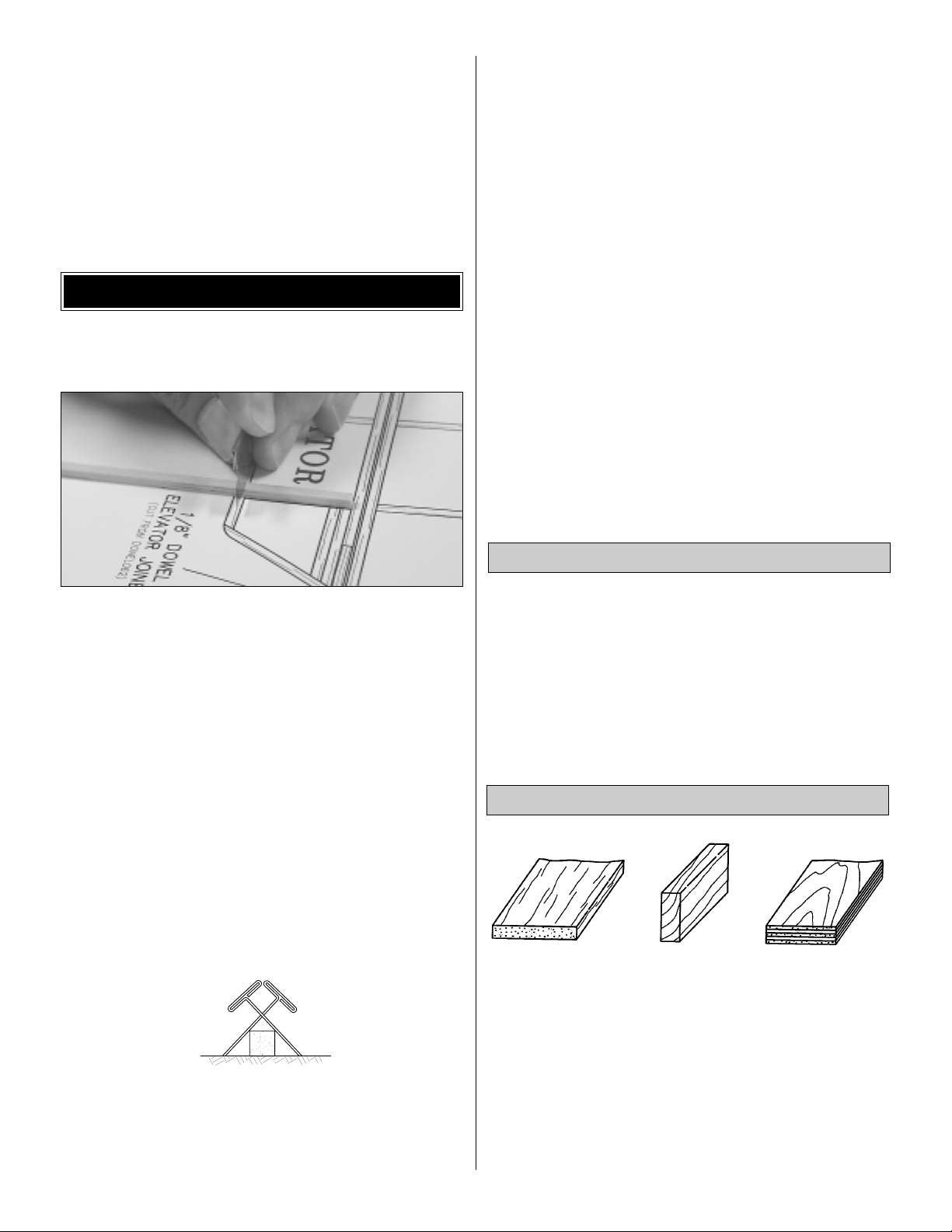
1. The easiest way to cut balsa sticks is with a single-edge
razor blade.To do so, position the stick over the plan, then
place the razor blade on the stick where you wish to cut it.
Press down lightly on the razor blade to mak e a mark where
the stick is to be cut.
2.Take the stick off the plan and cut it over a cutting mat or
a leftover piece of wood
(Okay, if you're careful you could go
ahead and cut the stick right over the plan, but if y ou do, you
may cut through the plan protector and allow the CA to soak
through, gluing the structure to the plan).
3.Because of the small balsa sticks used in the tail, small Tpins may be used to hold the sticks to your building board,
but only where necessary.Use small T-pins (HCAR5100) or
small straight pins found in craft stores.Do not stick pins into
the sticks near the ends, or the wood may split.
4. If you have difficulty with the T-pins splitting the small
sticks, an alternate method is to use the “crossed-pin”
technique.Insert the T-pins into the building board in a crisscross fashion to hold the sticks to the plan.
5.When applying CA, be careful to not glue your fingers to the
structure. In the process of
unsticking
your fingers you can
inadvertently damage the structure, thus requiring repairs and
adding additional weight
(not to mention the aggravation!)
.
6. Sanding requires a light touch to avoid damage.We found
the best method for sanding is to use light strokes in the
direction of the longest sticks. Be certain the sandpaper is
thoroughly bonded to the bar sander.Lifted edges will catch
the structure causing damage. Use medium-grit sandpaper
such as 120 or 150.
7. One of the best ways to insure a lightweight model is to
build neatly. Good-fitting glue joints with minimal adhesive
are stronger, lighter and ha v e a better appear ance than poorfitting joints with too much CA.Of course, you should take this
approach with all of your projects! Use CA applicator tips
(GPMR6033) to control and pinpoint the amount of CA.
8. Build over a flat surface. Cover the plans with Great
Planes Plan Protector (GPMR6167) or wax paper so the
parts will not adhere to the plan.
Fuse = Fuselage
LE = Leading Edge (front)
TE = Trailing Edge (rear)
Stab = Stabilizer
" = Inches
Elev = Elevator
LG = Landing Gear
Ply = Plywood
Types of Wood
Common Abbreviations
IMPORTANT BUILDING NOTES
5
Page 6
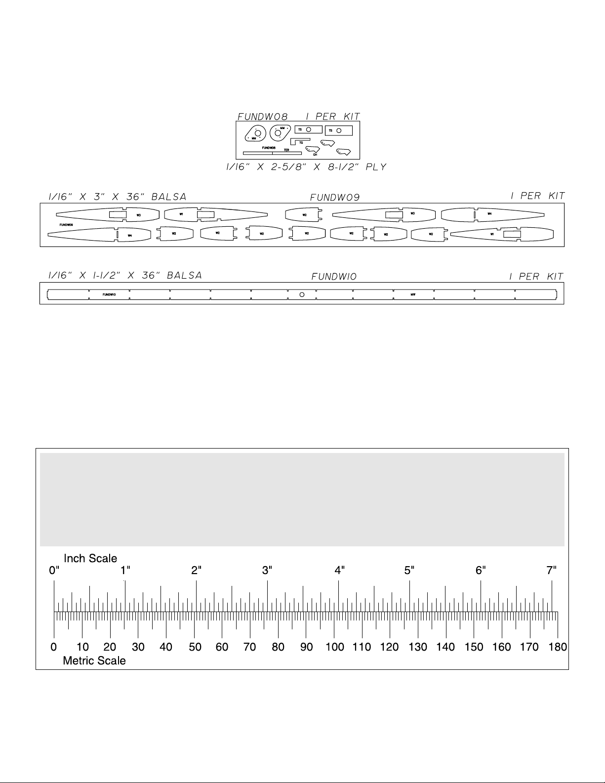
1/64" = .4 mm
1/32" = .8 mm
1/16" = 1.6 mm
3/32" = 2.4 mm
1/8" = 3.2 mm
5/32" = 4.0 mm
3/16" = 4.8 mm
1/4" = 6.4 mm
3/8" = 9.5 mm
1/2" = 12.7 mm
5/8" = 15.9 mm
3/4" = 19.0 mm
1" = 25.4 mm
2" = 50.8 mm
3" = 76.2 mm
6" = 152.4 mm
12" = 304.8 mm
18" = 457.2 mm
21" = 533.4 mm
24" = 609.6 mm
30" = 762.0 mm
36" = 914.4 mm
6
DIE-CUT PATTERNS
Metric Conversions
Page 7
❏ 1.Unroll the plan sheet. Re-roll it inside out to make it lie flat.
❏ 2. Remove all parts from the box. As you do, figure out the
name of each part by comparing it to the plans, the die page and
the parts list. Save all leftovers. If any of the parts are difficult to
remove from their die sheets, do not force them. Instead, cut
around the part with a hobby knife. After removing the parts,
lightly sand the edges to remove any die-cutting irregularities.
❏ 1. Place the wing portion of the plan over your flat
building board. Cover the wing plan with Great Planes Plan
Protector or wax paper.
❏ 2.Locate the die-cut 1/16" [1.6mm] balsa ribs W1 through
W4, the main web (MW) and the die-cut 1/16" [1.6mm]
plywood parts.
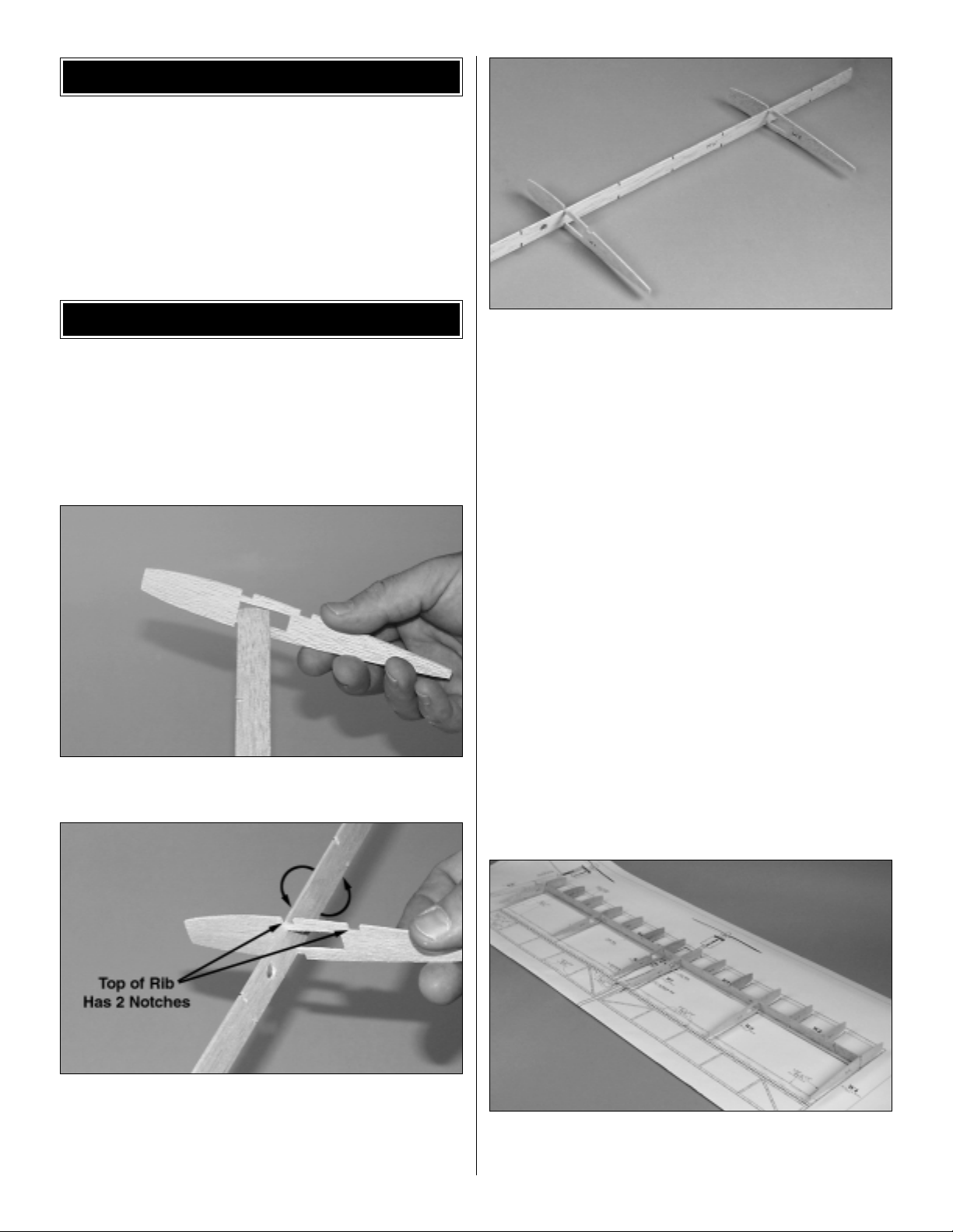
❏ 3. Inser t the right end of the main web into the opening
in rib W1 as shown.
❏ ❏ 4. Place rib W1 into the notch shown on the plan by
twisting it into position on the main web.W1 should be lined up
with the spar notch.The top of the rib is the side with two spar
notches. Be certain the rib is on the main web with these
two notches up. Glue W1 perpendicular to the main web.
❏ ❏ 5.Using the same procedure, insert W3 onto the main
web as shown on the plan. Glue W3 perpendicular to the
main web.
❏ 6. Repeat steps 3, 4 and 5 for the left side of the wing.
❏ 7. Locate the two 1/8" x 1/4" x 36" [3.2 x 6.4 x 910mm]
balsa sticks and cut them to 35" [889mm] in length. These
make up the top and bottom spar.
❏ 8.Pin one of the spars in place over the plan.This will be
the bottom spar.
❏ 9. Place the main web with the two W1 and two W3 ribs
onto the bottom spar. Carefully align the ribs in place over
the plan. Be sure that each rib is perpendicular to the
building surface.
❏ 10. Glue rib W4 to the main web at each end of the
bottom wing spar.
❏ 11. Glue each of the W2 half-ribs to the main web.
❏ 12. Make sure that ribs W1, W3, W4 and the main web
are in contact with the bottom spar. Glue the r ibs and the
main web to the bottom spar with thin CA.
BUILD THE WING
GET READY TO BUILD
7
Page 8
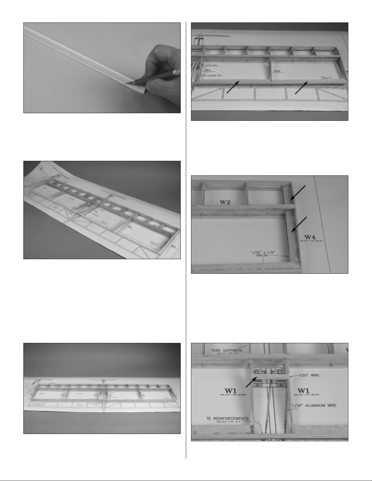
❏ 13. Use a hobby knife with a #11 blade to remove the
flashing from the shaped 36" balsa leading edge. NOTE:
The leading edge is symmetrical – there is no
top
or
bottom
.
❏ 14. Cut the leading edge to a length of 35" [889mm].
❏ 15. Beginning on the right side of the wing, glue the
leading edge to rib W4 with medium CA.Position the leading
edge so it is centered on the rib.When the glue has set, glue
the leading edge to W4 on the left side of the wing.Continue
to glue the leading edge to each of the W2 and W3 ribs for
the entire length of the wing, making sure that each rib is
centered on the leading edge.
❏ 16.Position and glue the top spar in place in the notches
on the top of the wing above the main web.
❏ 17.Cut one of the 3/16" x 3/16" x 36" [4.8 x 4.8 x 910mm]
balsa sticks to a length of 35" [889mm] to make the wing
trailing edge.Glue the trailing edge to ribs W1, W3 and W4.
❏ 18. Cut both 1/16" x 1/2" x 24" [1.6 x 13 x 610mm] balsa
TE supports to fit between W1 and W3 and between W3
and W4.Do this for the left and right side of the wing, gluing
them into place. Be certain the supports are centered
vertically on the TE.
❏ 19. Fit the remaining 1/16" x 1/2" x 24" [1.6 x 13 x
610mm] balsa stick between the trailing edge and the
leading edge at rib W4. When you are satisfied with the fit
glue them into place. Do this for both the left and right end
of the wing.
❏ 20. Glue the 1/8" x 1/4" x 2" [3.2 x 6.4 x 51mm] balsa
servo support into the two remaining notches on ribs W1.
8
Page 9

❏ 21. Locate both die-cut 1/16” [1.6mm] plywood tube
supports. Glue the narrower support to the back of the
leading edge in the center of the wing.
❏ 22. Glue the remaining tube suppor t to the back of the
main web. Be sure the hole in the main web and the rear
tube support align.
❏ 23. Push a T-pin through the exact center of the tube
support on the back of the LE, all the way through the
leading edge. This will be your
pilot hole guide
for drilling a
hole through the leading edge.
❏ 24. Drill a 1/8" [3.2mm] pilot hole through the pin hole
guide. Once you are satisfied that the pilot hole is through
the center of the forward tube support, drill a 5/16" [7.9mm]
hole through the leading edge.
❏ 25. Lightly and carefully sand the entire wing. The wing
is light and too much force could damage it.
❏ 26. Test fit the fiberglass fuselage tube into the wing.
Make any adjustments to the mounting holes needed for the
tube to slide through the wing. Cut a 5/16" [7.9mm] opening
in the trailing edge of the wing to allow the tube to pass
through it. This opening must be exactly centered between
the W-1 ribs.
9
Page 10

❏ ❏ 1.Make the frame of the aileron as shown on the plan
from a 3/16" x 3/16" x 36" [4.8 x 4.8 x 910mm] balsa stick.
❏ ❏ 2. Cut the cross supports from a 1/8" x 3/16" x 36"
[3.2 x 4.8 x 910mm] balsa stick. Glue the cross supports in
place using the plan as a guide.
❏ ❏ 3.From a leftover piece of 3/16" x 3/16" [4.8 x 4.8mm]
balsa stick, cut the control horn support brace to the
shape shown on the plan.
❏ ❏ 4. Glue the control horn suppor t brace to the aileron
as shown on the plan.Do not glue the control horn in place.
The control horn will be glued in after the aileron is covered.
❏ 5. Repeat steps 1 – 4 for the left aileron.
❏ 1. Cover the fin area of the plan with Great Planes
Plan Protector.
❏ 2. Make the bottom of the fin and the center fin post
from the 3/16" x 3/16" x 36" [4.8 x 4.8 x 910mm] balsa stick.
Pin the parts to your building board as you proceed.
❏ 3. Fit and glue the rest of the cross-brace structure from
one of the 1/8" x 3/16" x 36" [3.2 x 4.8 x 910mm] balsa
sticks. Place a few pins around the structure to suppor t it.
This will be helpful as you move through the steps of
wrapping the laminated frame of the fin.
Build the Fin
BUILD THE T AIL SURF ACES
BUILD THE AILERONS
10
Page 11

❏ 4. Inser t T-pins into the building board following the line
of the inside perimeter of the fin. This will help guide the
balsa laminate that will create the fin.
❏ 5. Use Isopropyl Alcohol or water to wet one side of the
three 1/16" x 3/16" x 24" [1.6 x 4.8 x 610mm] balsa sticks
allowing them to soften, so they can be bent around the T-pins.
Allow the sticks to sit for a few minutes before proceeding.
❏ 6.Glue the balsa sticks in place.Begin by gluing one end
of the stick to the fin using medium CA. Work the stick
around the fin using the T-pins as a guide. As you proceed,
glue the stick to the wooden structure. Carefully work the
balsa stick around the fin.
❏ 7. Repeat this process for the second and third stick,
gluing each one to the other.
❏ 8. Trim the excess strips to match the shape of the fin.
After the balsa has completely dried, lightly sand the fin.
❏ 9.Round the perimeter of the fin by sanding as shown on
the plan sheet.
Laminating is an interesting and fun way to make a strong,
yet lightweight structure. Now that you know how to do it,
you should be able to do the same thing to the horizontal
stab and elevator in much less time. Let's get started!
11
Page 12

❏ 1.Cover the stab and elevator area of the plan with Great
Planes Plan Protector.
❏ 2. Cut the stab trailing edge and the elevator leading
edge from the 3/16" x 3/16" x 36" [4.8 x 4.8 x 910mm] balsa
stick, then pin them to the plan.
❏ 3. Build the cross-brace structure in the same manner as
the fin from 1/8" x 3/16" x 36" [3.2 x 4.8 x 910mm] balsa
sticks. The elevator control horn brace should be made
from leftover 3/16" x 3/16" [4.8 x 4.8mm] the same as the
control horn braces for the ailerons. Do not glue the control
horn in place at this time. It will be installed after the elevator
is covered. Place a few pins around the structure to support
it and insert T-pins into the building board following the line of
the inside perimeter of the fin. This will help guide the balsa
laminate that will create the frames of the stab and elevator.
❏ 4. Locate three 1/16" x 3/16" x 36" [1.6 x 4.8 x 910mm]
balsa strips. These will be wrapped around the stab and
elevator the same way that you did the fin. Be sure you
follow the same steps for wetting the wood as was done for
the fin.
❏ 5. Wet the wood and allow it soften for a few minutes.
Glue the balsa laminate in place.Begin by gluing one end of
the strip to the stab at the location shown in the photo.
❏ 6.Work the strip around the perimeter of the stab and the
elevator. When you get back to the point where you first
glued the strip you will have to cut off the e xcess balsa stick.
This will allow you to complete the laminate wrap.
❏ 7. Repeat the process for the second and third balsa
laminate strips, gluing them to one another.
❏ 8. After the balsa has dr ied, lightly sand the structure.
The entire perimeter should be rounded to match the crosssection on the plan.
Build the Stab and Elevator
12
Page 13

❏ 9. Use a hobby knife to separate the stab and elevator.
❏ 10. Use a sanding bar to bevel the leading edge of the
elevator to the shape shown on the elevator cross-section
on the plan.
That's it for the tuff stuff! Now you can move ahead with the
process of assembling the plane.
❏ 1.Use a razor saw or a Moto-Tool with a cut-off wheel to cut
the fiberglass fuselage tube to a length of 24-5/8" [625.5mm].
Refer to this photo for the following two steps.
❏ 2.Wrap one end of the tube with 5" [130mm] of masking
tape.This will be the aft end of the fuselage tube.Mark a line
on the tape 4-7/8" [124mm] from the end of the tube.
❏ 3. From the mark you made, draw a line parallel with the
tube to the end of the tube. Draw a second line parallel with
the line you just made the thickness of the fin. (This should
be 3/16" [4.8mm], but may be less because of sanding.)
❏ 4. CAUTION:Wear eye protection for this step! Use a
Dremel®tool with a cut-off wheel or a razor saw to cut the
tube on the lines to create a slot for the fin.Hint: Cut the slot
a bit narrow to begin with, so the fin will fit well.
❏ 5. Test fit, but do not glue the fin into the slot. Make
adjustments if necessary.
❏ 6. Sand the 1/4" x 2" [6.3 x 50mm] wooden dowel until it
will fit into the front end of the fuselage tube. Be sure to
leave a little room for glue. Fit the dowel into the tube, flush
with the end of the tube and permanently glue it into position
with thin CA.
❏ 7.Slide the fuselage tube into the wing. Position the wing
so the leading edge of the wing is 2-1/4" [57mm] from the
front of the tube. Do not glue it in place yet!
Prepare the Fuselage Tube
BUILD THE FUSELAGE
13
Page 14

❏ 8. Lay the bottom of the wing flat on the bench.
IMPORTANT! The top of the wing is the side that has the two
servo rails.Temporarily place the fin into the slot at the end of
the tube. Rotate the tube until the fin is 90 degrees to the
bench.Use a triangle to verify that the fin is set at 90-degrees.
❏ 9. Once you are satisfied with the placement, use CA to
glue the fuselage tube to the wing at the leading edge, the
main web and the trailing edge.
❏ 10.Locate the die-cut 1/16" [1.6mm] ply top and bottom
trailing edge reinforcement. Glue one to the top of the
trailing edge and one to the bottom of the trailing edge as
shown in the photo. Apply them at the same time and use
your fingers to apply equal pressure to the top and bottom
at the same time. Any gap you have can be filled with
medium or thick CA and hardened with CA accelerator.
❏ 11. Hold the die-cut 1/16" [1.6mm] ply engine thrust
gauge on the top of the fuselage tube. Sand the front of the
tube to match the angle of the gauge to provide the correct
motor down thrust.
Landing gear is optional on the Fundango.With gear, handlaunching is not necessary as the plane can take-off and
land on hard surfaces. The landing gear also protects the
propeller on rough landings. The gear does, however, add
weight and drag. If you fly over grassy areas you may
consider omitting the gear. Soft landings in the grass are
done easily without damaging the propeller.
❏ 1. Cut the 1/16" x 30" [1.6 x 760mm] wire into three
pieces of 15-5/8" [397mm], 6" [152mm] and 9" [230mm].
❏ 2. Bend the 15" [380mm] wire as shown on the landing
gear template on the plan.
❏ 3. Use a felt-tip pen to mark the wire 1" [25mm] from the
top as shown in the drawing. Bend the wire back at a 90
degree angle.
❏ 4.Cut the gear in half as shown in the photo and the drawing.
Build the Landing Gear (Optional)
14
Page 15

❏ 5. Now there is a left and right main landing gear.
❏ 6. Bend the 6" [152mm] wire as shown on the
cross-
brace
template on the plan.
❏ 7. Bend the tail skid from the remaining piece of 9"
[230mm] wire as shown on the plan. Use a needle nose
pliers to make the circular bend in different spots until you
have formed the curved end. Cut off the excess wire.
❏ 1. Cover the front 2" [50mm] of the fuselage tube with
masking tape, so you can mark where to drill the holes for
the landing gear.
❏ 2. Use a ballpoint pen to mark the tube 1" [25mm] and
1-1/16" [27mm] from the end. Be certain the marks are on
the tube so that when the holes are drilled and the landing
gear is mounted, the wings will be level when the model is
resting on the gear.
❏ 3. Drill 1/16" [1.6mm] holes all the way through the
fuselage tube at the marks you made.
❏ 4. Inser t the landing gear into the tube. Wrap the gear
and the tube tightly with string or thread (not included in the
kit). Saturate the string with thin CA.
❏ 5.Attach the cross-brace 1-3/8" [35mm] above the bend in
the axle. Wrap the joints tightly with string or thread and
saturate with thin CA.
❏ 6. Drill a 1/16" [1.6mm] hole for the tail skid 6" [152mm]
from the aft end of the tube.
Mount the Landing Gear
15
Page 16

❏ 7. Attach the tail skid the same way you did the landing
gear with string and CA.
❏ 8. Mount the wheels and secure them with the two
nylon retainers.
❏ 1. If you haven't done so already, sand all wood parts of
the model smooth with 320-grit, then 400-grit sandpaper.
❏ 2. Use compressed air (be careful!), a dust brush or a
tack cloth to remove balsa dust from the model.
❏ 3. Determine what material you will be covering the
model with. If using Top Flite EconoKote or MonoKote, the
model is ready to cover. If using Coverite Micafilm, coat the
areas to be covered with Coverite Balsarite (COVR2500).
Be certain you use the formula for Micafilm (fabric) and not
the formula for regular film covering.
The following procedure must be followed to assure a
straight, strong wing.
❏ 1. Cover the bottom, then the top of the wing, but do not
shrink the covering until instructed to do so.Do your best
to minimize wrinkles without applying heat, thus reducing the
amount of shrinking that will be required later on.
❏ 2.Cover the bottom, then the top of both ailerons the same
way. Do not shrink the covering until instructed to do so.
❏ 3. Cut both 3/4" x 1" [9 x 25mm] hinge strips into (12)
hinges as shown on the plan.
❏ 4. Use a hobby knife to cut 1/8" [3mm] hinge slots in the
trailing edge of the wing and the leading edge of the ailerons
where shown on the plan.
❏ 5. Join the ailerons to the wing with the hinges. Apply 3
drops of thin CA to each side of each hinge.
❏ 6.Proceeding slowly, heat the top and bottom of one side
of the wing to shrink the covering. Heat each side a little at
a time, so the top and bottom shrink simultaneously. Use
only enough heat to remove the wrinkles. Avoid fully
shrinking and tightening the covering. After the wrinkles
have disappeared, use a covering iron to bond the covering
to the ribs, to the servo mounting rails, to the aileron crossbraces and to the control horn brace.
❏ 7. Use the same procedure to remove the wrinkles from
the other side of the wing and the ailerons.
❏ 8.Trim the covering from the servo mounting rails and the
control horn braces in the ailerons.
❏ 1.Cover both sides of the fin, shrinking the covering evenly
and only as much as necessary to remove the wrinkles.
❏ 2. Cover the stab and the elevator.
❏ 3. Join the elevator to the stab with the hinges, then heat
the covering evenly on both sides to remove the wrinkles.
Cover the Tail Surfaces
Cover the Wing and Ailerons
Prepare the Model for Covering
CO VER THE MODEL
16
CUT HINGE SLOT
WITH HOBBY KNIFE
AND #11 BLADE
ASSEMBLE, THEN APPLY 3 DROPS
OF THIN CA TO CENTER
OF HINGE, ON BOTH SIDES
Page 17

❏ 1. Dr ill two #60 (.040") [1mm] holes through the punch
marks in the die-cut 1/16" control horns.
❏ 2. Glue the control horns into position in each of the
ailerons and the elevator, making sure they are vertical to
the control surface.
❏ 1. Slide the stab and elevator onto the fuselage tube.
Make sure you hav e a good fit betw een the tube and the slot
in the stab. Sand or shim the stab as needed to get a good
fit. Be sure that the elevator moves up and down freely
without any binding when the stab is mounted.
❏ 2. Make sure that the stab is parallel with the wing as
shown in the photo above .Glue the stab to the fuselage tube
with medium CA.
❏ 3. Slide the fin into the slot in the rear of the fuselage
tube. Be sure that the fin is 90 degrees to the stab and
parallel with the fuse, then glue the fin into the slot.
❏ 1. Drill a 5/64" [2mm] hole for the battery hook through
one side of the fuselage tube between the leading edge of
the wing and the landing gear.
(If you don't have a 5/64"
[2mm] drill bit you could use a 1/16" [1.6mm] drill bit, but
you'll have to enlarge the hole with a hobby knife.)
❏ 2.Make the battery hook from .074 x 2" [1.9 x 50mm] wire.
Mount the Battery
Mount the Stab and Fin
Mount the Control Horns
FINAL ASSEMBLY
17
90˚
90˚
Page 18

❏ 3. Use medium CA to glue the hook into the hole you
drilled in the fuselage tube.
❏ 4. Hook two #64 rubber bands around the fuselage tube
behind the wing, then connect them to the battery hook.
Mount the battery pack between the wing and the rubber
bands. Later, the exact location of the battery will be
determined to balance the model.
❏ 1.Glue both die-cut 1/16" [1.6mm] plywood motor mounts
together to form a 1/8" [3.2mm] motor mount.
❏ 2.Drill a 1/8" [3.2mm] hole though the three punch marks
in the motor mount.
❏ 3.Drill a 3/32" [2.4mm] hole into the center of the wooden
dowel in the front of the fiberglass pushrod.
❏ 4.Attach the motor mount to the front of the fuselage with
a #4 washer and a #4 x 1/2" [3.2mm] screw.
❏ 5. Use electrical solder to tin the end of the white and
blue wires coming from the speed control.Do not use silver
solder as it is not suitable for electrical purposes and the flux
will corrode the wires.
❏ 6.Solder the blue wire (negative) on the speed control to
the tab on the motor that has a red dot (positive).Solder the
white wire (positive) to the other tab on the motor
(negative). Note: The speed control is connected to the
motor “backwards” due to the gear reduction, which would
otherwise cause the propeller to turn backwards.
Mount the Motor and Speed Control
18
Page 19

❏ 7. Mount the motor and gear box to the motor mount as
shown, using the screws included with the system.
❏ 8. Make a tapered 3/16" spacer from leftover balsa and
glue it to the fuselage under the aft end of the motor as
shown on the plan.
❏ 9.Secure the back of the motor to the fuselage with nylon
tape or a tie wrap (not included).
Final motor connections will be done when the servos and
receiver are installed.
The Hitec Feather Receiver is shown in these instructions.
❏ 1. If you haven't yet done so, trim the covering from the
servo bay as shown.
❏ 2. Connect the aileron servo to slot number one on the
receiver, the elevator to number two and the speed control
to number three.
❏ 3.Insert the receiver into the servo bay opening along side
of the fuselage. (If you are using a larger receiver you can
mount it outside the wing and secure it with rubber bands.)
❏ 4.Drill 1/16" [1.6mm] holes in the servo rails for mounting
the servos. Add a drop of thin CA to the holes and allow to
harden. Mount the servos to the rails.
Now let's make the pushrods!
❏ 5. Cut the 1/16" x 24" [1.6 x 610mm] aluminum tube into
one 17-1/4" [438mm] piece and two 3-3/8" [86mm] pieces to
make the pushrod tubes. Hint: The tubing is easily cut by
placing the edge of your hobby knife blade on the tube, then
rolling the tube back and forth until it cuts through.
❏ 6. Cut the .03" x 10" [.76 x 254mm] wire into four 1-1/2"
[38mm] pieces and two 3" [76mm] pieces.
Mount the Radio
19
Page 20

❏ 7. Place a couple of drops of medium CA on the end of
one 3-3/8" [86mm] pushrod tube. Insert a 1-1/2" [38mm]
wire into the tube approximately 1/2" [13mm]. Allow the CA
to harden, or give it a “spritz”of CA accelerator.Do the same
at the other end of the tube. Repeat for the other 3-3/8"
[86mm] tube.These pushrods will be for the ailerons.
❏ 8. Follow the same procedure for the 17-1/4" [438mm]
tube, inserting the 3" [76mm] wire 1/2" [13mm] into each end
of the tube.This will be the elevator pushrod.
❏ 9.Make a Z – bend at one end only of all three pushrods
as shown.
❏ 10.Using the servo horns supplied with your servos, make
one
single
servo arm and one
twin
servo arm as shown.
❏ 11. Center the aileron servo and mount the twin servo
arm to it.
❏ 12. Insert the aileron pushrods that have the Z-bend into
the aileron control horns.
❏ 13. Center the aileron, then mark the end of the pushrod
wire where it attaches to the servo.Make another Z- bend at
the mark and insert it into the ser vo horn. Do this for both
aileron servos.
❏ 14.Use the same procedure to install the elevator pushrod.
❏ 15. Mount the speed control and the on/off switch to the
top of the fuselage with double-sided foam mounting tape
(not included).
❏ 16. Extend the receiver antenna to the back of the
fuselage and hold it to the stabilizer with cellophane tape.Be
certain there is no way that the antenna can reach the
propeller! Never coil-up the antenna, nor cut it.The antenna
length is tuned to a certain radio frequency.
20
Page 21

❏ 1. For safety, remove the propeller from the motor. Move
the throttle stick to the off position. Connect the charged
battery to the speed control. Turn on the transmitter, then
follow the instructions that came with your speed control to
turn on the receiver.
❏ 2.Center the trims on the transmitter.Operate the servos
by moving the control sticks. Check that the servos respond
in the correct direction as shown in the diagram. If
necessary, use the servo reversing function in your
transmitter to get the controls to respond correctly.
❏ 3. Operate the controls with the transmitter and use a
ruler to measure the throws. Use the ATV function in the
transmitter to set the control throws according to the chart
that follows.If your transmitter does not have dual rates, set
up the Fundango on the low rate settings.After you become
accustomed to the way the Fundango flies, you may begin
increasing the throws until you get to the high-rate settings.
❏ 4. Switch off the transmitter and disconnect the batter y.
Note:This section is VERY important and must NOT be
omitted! A model that is not properly balanced will be
unstable and possibly unflyable.
❏ 1. Use 1/8"-wide tape or a felt-tip pen to accurately mark
the balance point on the top of the wing on both sides of the
fuselage.The balance point (CG) is located 3-1/16" [78mm]
from the leading edge as shown in the sketch and on the
plan.This is the balance point at which the Fundango should
balance for your first flights. If, after initial trim flights you
have become accustomed to the way the Fundango flies,
you may wish to experiment by shifting the balance point
3/16" [5mm] forward to 1/2" [13mm] back to change the
flying characteristics.Moving the balance point forward may
improve the stability and make the model easier to fly, but it
may not climb as rapidly and will be less aerobatic. Moving
the balance aft makes the model more maneuverable and
aerobatic, but it could be too difficult to control if you are not
an experienced pilot. In any case, start at the balance point
recommended and do not at any time balance the model
outside the recommended range.
Balance the Model
These are the recommended control throws:
High rate Low rate
Elevator: 2" [51mm] up 1" [25mm] up
2" [51mm] down 1" [25mm] down
Ailerons: 1-1/8" [29mm] up 1/2" [13mm] up
1-1/8" [29mm] down 1/2" [13mm] down
IMPORTANT: The Fundango has been extensively
tested.These are the control throws at which it flies best.
If, after you become comfortable with the way the
Fundango flies, you would like to adjust the thro ws to suit
your taste, that is fine.However , on the high-rate settings
the Fundango can already do all the maneuvers “in the
book,”so there shouldn't be any requirement to increase
the throws. Doing so could make the model too difficult
to control, so remember, “more is not always better.”
Warning: Whenever the model is not being flown or set
up, the battery should be disconnected.
Set the Control Throws
PREPARE THE MODEL FOR FLYING
21
3-CHANNEL RADIO SETUP
(STANDARD MODE 2)
ELEVATOR MOVES UP
4-CHANNEL
TRANSMITTER
RIGHT AILERON MOVES UP
LEFT AILERON MOVES DOWN
4-CHANNEL
TRANSMITTER
MOTOR TURNS
4-CHANNEL
TRANSMITTER
3-1/16"
Center of Gravity:
3-1/16" From Leading Edge
Total Range: 2-7/8" to 3-9/16"
Page 22

❏ 2.With the battery mounted to the fuselage, lift the model
upside-down at the balance point.If the tail drops, the model
is “tail heavy” and you must shift the battery pack forward to
balance the model. If the nose drops, it is “nose heavy” and
you must shift the battery aft to balance the model.
❏ 3. Shift the battery pack until the model balances at the
balance point recommended. Use narrow masking tape or a
felt-tip pen to mark the location of the battery pack on the
bottom of the wing. Be certain this is where you always
mount the battery pack when it's time to fly so the model will
be properly balanced.
Follow the transmitter battery charging procedures in your
radio's instruction manual.Charge the transmitter batteries the
night before you go flying and at other times as recommended
by the radio manufacturer.
Charge the motor battery following the instructions that
came with the battery charger and the guidelines in the front
of this manual.
No matter if you fly at an AMA sanctioned R/C club site or if
you fly somewhere on your own, you should always have
your name, address, telephone number and AMA number
on or inside your model. It is required at all AMA R/C club
flying sites and AMA sanctioned flying events. Fill out the
identification tag on the center spread of this manual and
place it on or inside your model.
Before you fly you should perform one last overall inspection
to make sure the model is truly ready to fly and that you
haven't ov erlook ed anything.If you are not thoroughly familiar
with the operation of R/C models, ask an experienced
modeler to perform the inspection. Check to see that you
have the radio installed correctly and that all the controls are
connected properly. The motor must also be checked by
confirming that the prop is rotating in the correct direction and
the motor sounds like it is reaching full power. Make certain
all control surfaces are secure, the pushrods are connected,
the controls respond in the correct direction, radio
components are securely mounted and the C.G.is correct.
Ground check the operational range of your r adio bef ore the
first flight of the day. With the transmitter antenna collapsed
and the receiver and transmitter on, you should be able to
walk at least 100 feet away from the model and still have
control. Have an assistant stand by your model and, while
you work the controls, tell you what the control surfaces are
doing. Repeat this test with the motor running at various
speeds with an assistant holding the model, using hand
signals to show you what is happening. If the control
surfaces do not respond correctly, do not fly! Find and
correct the problem first. Look for loose servo connections
or broken wires, corroded wires on old servo connectors,
poor solder joints in your battery pack or a defective cell, or
a damaged receiver crystal from a previous crash.
NOTE: It is possible for the motor to cause interference.If you
experience a range problem or notice the servos “glitching,”
install an additional .01 µF capacitor between the motor
leads, then repeat the range check with the motor running.
For the longest flight duration and to get the most from a new
battery, the battery should be cycled. “Cycling” a battery
means to fully charge (“peak” charge) the battery, then to
discharge it. Many batter y chargers have peak charging and
automatic discharging capabilities. If you do not have a
charger that is able to discharge batteries, you can discharge
the battery yourself by running the motor with the propeller
attached until the propeller spins slowly. Charge and
discharge the battery 3 or 4 more times on the ground before
flying. Be sure to remove the battery from the airplane
between each cycle and allow it to cool before recharging.
Use 400-grit sandpaper to remove imperfections along the
edges of the propeller.For the best performance, use a Top
Flite Precision Magnetic Prop Balancer™(TOPQ5700) to
balance the propellers (this is a necessity on glow-powered
engines, but less critical on small electric models).
Examine the Propeller
Cycle the Batteries
PERFORMANCE TIPS
Range Check
Ground Inspection
Identify Y our Model
Charge the Batteries
PREFLIGHT
22
Page 23

1. “Break-in” the motor by running it at 1/4 throttle without the
propeller for at least ten minutes.This will ensure that the motor
will provide full power f or the first flight and will extend the ov erall
life of the motor.Install the propeller onto the gear box shaft.
2.Using multiple battery packs for successive flights may cause
the motor to become excessively hot, thus causing damage.
Allow the motor to cool for at least 10 minutes between flights.
Though the Fundango is a “Park Flyer,” the best place to fly
any model is at an AMA chartered club field. Club fields are
set up for R/C flying making your outing safer and more
enjoyab le.We recommend that you join the AMA and a local
club so you can have a safe place to fly and have insurance
to cover you in case of a flying accident.The AMA address
and telephone number are in the front of this manual.
If there is no club or R/C flying field in your area, find a
suitable site that is clear of trees, telephone poles, buildings,
towers, busy streets and other obstacles. Since you are not
flying at a sanctioned AMA site, be aware that there may be
others like yourself who could be flying nearby.If both of your
models happen to be on the same frequency, interference
will likely cause one or both of the models to crash. An
acceptable minimum distance between flying models is five
miles, so keep this in mind when searching for a flying site.
In addition to obstacles, it is important to be aware of people
who may wander into the area once you begin flying.At AMA
club flying sites it is a severe rule infraction to fly over others.
You should avoid flying over people no matter where you fly.
R/C models tend to attract onlookers whose numbers can soon
multiply forming small, uncontrolled crowds. Onlookers pose
two main problems.First is the danger of actually crashing your
model into a person, causing injury .Second is the distraction of
those who ask you questions while you are trying to
concentrate on flying.To minimize or avoid this problem, have
an assistant standing by who can spot people who wander into
your flying site (so you can av oid flying ov er them) and who can
perform “crowd control”if people start to gather.
Note: Failure to follow these safety precautions may result
in severe injury to yourself and others.
Get help from an experienced pilot when learning to
operate motors.
Use safety glasses when running motors.
Do not run the motor in an area of loose gravel or sand;the
propeller may throw such material in your face or eyes.
Keep your f ace and body as well as all spectators a wa y from
the path of the propeller as you start and run the motor.
Keep items such as these away from the prop: loose
clothing, shirt sleeves, ties, scarfs, long hair or loose objects
(pencils, screw drivers) that may fall out of shirt or jacket
pockets into the prop.
The electric motor and battery used in the Fundango are very
powerful and the spinning propeller has a lot of momentum;
therefore, if you touch the propeller while it is spinning it may
inflict severe injury. Respect the motor and propeller for the
damage they are capable of and take whate ver precautions are
necessary to avoid injury. Always disconnect and remove the
motor battery until you are ready to fly again and always make
sure the switches are turned off before connecting the battery.
Be aware that the motor may suddenly start when you attach
the battery. Please keep away from the prop when attaching
the battery.
Read and abide by the following Academy of Model
Aeronautics Official Safety Code:
1. I will not fly my model aircraft in competition or in the
presence of spectators until it has been proven to be
airworthy by having been pre viously successfully flight tested.
2. I will not fly my model aircraft higher than approximately
400 feet within 3 miles of an airport without notifying the
airpor t operator. I will give right of way to and avoid flying in
the proximity of full scale aircraft. Where necessary an
observer shall be utilized to supervise flying to avoid having
models fly in the proximity of full scale aircraft.
3.Where established, I will abide by the safety rules for the
flying site I use and I will not willfully and deliberately fly my
models in a careless, reckless and/or dangerous manner.
7. I will not fly my model unless it is identified with my name
and address or AMA number, on or in the model.
1.I will have completed a successful radio equipment ground
check before the first flight of a new or repaired model.
2. I will not fly my model aircraft in the presence of
spectators until I become a qualified flyer, unless assisted
by an experienced helper.
3.I will perform my initial turn after takeoff away from the pit,
spectator and parking areas and I will not thereafter perform
Radio Control
General
AMA SAFETY CODE (EXCERPTS)
MOTOR SAFETY PRECAUTIONS
FIND A SAFE PLACE TO FLY
Motor Care
23
Page 24

maneuvers, flights of any sort or landing approaches over a
pit, spectator or parking area.
4. I will operate my model using only radio control frequencies
currently allowed by the F ederal Comm unications Commission.
IMPORTANT: The Fundango is a great park flyer that flies
smoothly and predictably, yet is surprisingly aerobatic. It
does not, however, possess the self-recovery characteristics
of a primary R/C trainer and should only be flown by
experienced RC pilots. If you know how to fly, but are not
experienced with aerobatic models, seek the assistance of a
competent, experienced R/C pilot who can check your model
for airworthiness and help you fly it.
The Fundango is capable of performing a broad range of
aerobatics - from simple loops and rolls to impressive rolling
circles. Have Fun!
Whether you have b uilt your Fundango with or without landing
gear, hand-launching is recommended for the first few flights
until you get the model properly trimmed and set up for flight.
Tur n on the transmitter and plug the battery into the speed
control. Turn on the receiver by following the instructions
that came with the speed control.
IMPORTANT: Confirm that the transmitter operates the
controls by moving the sticks and watching the surfaces
respond. Occasionally, electric models have been launched
with the transmitter turned off or the battery disconnected
from the speed control!
When ready to launch, an assistant should hold the model
by the sides of the battery pack just behind the landing gear
and raise the model above his head. Point the model into
the wind.With the pilot
(that would be you!)
standing behind
the plane, fully advance the throttle to start the motor. As
soon as the motor is at full power , the hand-launcher should
gently toss the plane into the air at a level or slightly noseup attitude. Be certain the model is being launched into the
wind and be immediately ready to make corrections to keep
the airplane flying straight, level and into the wind.
When the model has gained adequate flying speed under its
own power, gently pull the elevator stick back until the
airplane starts a gradual climb. Be gentle on the elevator
and don't panic. If you pull too hard and notice the model
losing speed, release the elevator stick and allow the model
to regain airspeed.
Continue a gradual climb and establish a gentle turn (away
from other people) until the model reaches an altitude of 75
to 100 feet.
Fly on low control rates until you have become accustomed
to the Fundango. If you find that the model is a bit of a
handful, throttle back to slow it down, allowing time to think
clearly and react.
Once at a comfortable altitude, the first priority is to adjust
the trims so the model flies straight and level.Continue to fly
around, executing turns and making mental notes (or having
your assistant take notes for you) of what additional
adjustments or C.G. changes may be required to fine tune
the model so it flies the way you like.
Before it's time to land, climb to a safe altitude and cut the
throttle to an idle and note how the model reacts. Do this a
few times so y ou know what to expect when it's time to land.
After you've gotten a f e w trim flights under your belt and you
are comfortable with the way the Fundango flies, you can
“cut it loose” and start flying some aerobatic maneuvers.
Remember to keep your maneuvers at a safe altitude until
you know what to expect.
The Fundango lands about the same as any other model, it
just requires much less space! When it's time to land, fly a
normal (but smaller) landing pattern and approach. Keep a
few clicks of power on until you are over the runway
threshold.This model does not stall hard on landing and will
3-point
nicely. If flying without landing gear, land with the
throttle off to avoid a prop strike.
If you have built the Fundango with landing gear you may take
off from a smooth surface—it probab ly won't takeoff from grass .
After you have trimmed the Fundango for flight and have
become familiar with its characteristics, you may execute
ROG takeoffs. Taking-off on the low rate settings is
recommended. Place the model on the r unway pointing into
the wind. Typically, with most R/C models it is best to
advance the throttle smoothly and allow the plane to build
up as much speed as possible before lifting off. However,
with the Fundango it is best to get the model into the air
quickly. To do this, advance the throttle rapidly and allow the
model to lift from the runway as soon as it reaches flying
speed—which should be about fifteen feet or less.You will
have little directional control until the model is in the air, but
if taking off into the wind the model should track fairly
straight on its own. Once in the air establish a climb the
same as when you were hand-launching.
Best of luck and happy flying!
ROG (Rise Off Ground) Takeoff
Landing
Flight
Takeoff
FLYING
Page 25

B C
Page 26

D A
2-View
Use these 2-views( or photocopy them)
to design your trim scheme.
 Loading...