

Page 1
WARRANTY
Great Planes®Model Manufacturing Co. box guarantees this kit to be free from defects in both material and workmanship at the date of purchase.
This warranty does not cover any component parts damaged by use or modification.In no case shall Great Planes’liability exceed the original cost
of the purchased kit. Further, Great Planes reserves the right to change or modify this warranty without notice.
In that Great Planes has no control over the final assembly or material used for final assembly, no liability shall be assumed nor accepted for any
damage resulting from the use by the user of the final user-assembled product. By the act of using the user-assembled product, the user accepts all
resulting liability.
If the buyer is not prepared to accept the liability associated with the use of this product, the buyer is advised to return this kit immediately
in new and unused condition to the place of purchase.
To make a warranty claim send the defective part or item to Hobby Services at the address below:
Hobby Services
3002 N. Apollo Dr.Suite 1
Champaign IL 61822
USA
Include a letter stating your name, return shipping address, as much contact information as possible (daytime telephone number, fax number, e-mail
address), a detailed description of the problem and a photocopy of the purchase receipt.Upon receipt of the package the problem will be evaluated as
quickly as possible.
READ THROUGH THIS MANUAL BEFORE STARTING
CONSTRUCTION. IT CONTAINS IMPORTANT
INSTRUCTIONS AND WARNINGS CONCERNING THE
ASSEMBLY AND USE OF THIS MODEL.
RV4PP03 V1.0 Entire Contents © Copyright 2004 Printed in USA
Champaign, IL
(217) 398-8970, Ext. 5
airsupport@greatplanes.com
INSTRUCTION MANUAL
Wingspan: 41-3/4 in [1060mm]
Wing Area: 368 sq in [23.7 dm
2
]
Airframe Weight: 11-1/2 oz [326 g]
Weight Ready to Fly: 18-1/2 to 22 oz [525–624g]
Wing Loading: 7.3–8.6 oz/sq ft [22.3–26.2 g/dm
2
]
Length: 38-1/4 in [972mm]
Radio: 4-channel with three micro servos
Motor: S-280 7.2 volt or 350 size, high power 7.2 volt
Page 2

INTRODUCTION.................................................................................2
SAFETY PRECAUTIONS...................................................................2
DECISIONS YOU MUST MAKE.........................................................3
Radio Equipment.........................................................................3
Speed Control .............................................................................3
Motor System..............................................................................3
Battery Recommendations..........................................................4
Performance Options ..................................................................4
Chargers......................................................................................5
Covering......................................................................................5
Building Board.............................................................................6
ADDITIONAL ITEMS REQUIRED......................................................6
Hardware & Accessories .............................................................6
Adhesives & Building Supplies....................................................6
Optional Supplies & Tools ...........................................................6
IMPORTANT BUILDING NOTES.......................................................6
DIE-CUT PATTERNS..........................................................................8
METRIC CONVERSIONS...................................................................8
BUILDING INSTRUCTIONS...............................................................9
BUILD THE T AIL SURFACES............................................................9
BUILD THE WING.............................................................................10
Build the Wing Panels...............................................................10
Join the Wing Panels.................................................................13
Build the Ailerons......................................................................14
BUILD THE FUSELA GE...................................................................16
Frame the Sides ........................................................................16
Finish the Fuselage ...................................................................18
Install the Pushrods...................................................................24
COVER THE MODEL .......................................................................26
Suggested Covering Sequence ................................................26
Add Washout.............................................................................26
FINAL ASSEMBLY...........................................................................27
Join the Tail Surfaces................................................................27
Hook Up the Controls................................................................28
Mount the Landing Gear ...........................................................28
Assemble the Gear Drive..........................................................29
MOUNT THE CANOPY, COWL & WHEEL PANTS ..........................30
PREPARE THE MODEL FOR FLYING ............................................32
Balance the Model ....................................................................32
Set the Control Throws..............................................................33
PREFLIGHT......................................................................................34
Charge the Transmitter Batteries ..............................................34
Identify Y our Model....................................................................34
Ground Inspection.....................................................................34
Range Check.............................................................................34
PERFORMANCE TIPS.....................................................................35
Cycle the Batteries....................................................................35
Examine the Propeller ...............................................................35
Motor Care ................................................................................35
Oil the Wheels ...........................................................................35
MOTOR SAFETY PRECAUTIONS ..................................................35
AMA SAFETY CODE (excerpts).....................................................35
FIND A SAFE PLACE TO FLY.........................................................36
FLYING .............................................................................................36
Takeoff.......................................................................................36
Flight..........................................................................................36
Landing......................................................................................37
ROG (Rise off Ground) Takeoff.................................................37
2-VIEW DRAWING...................................................Back Cover Page
FUSELAGE/WING PLAN...............................Center Pull-Out Section
Congratulations and thank you for purchasing the Great
Planes RV-4 Park Flyer. The RV-4 Park Flyer is one in a
series of Park Flyers from Great Planes designed to be
flown in small areas. Park Flyers are a relatively new class
of small, lightweight, slow-flying, fast-b uilding models.Since
Park Flyers are small and fly slowly, little space is required.
A nearby park, schoolyard or vacant lot becomes an
impromptu flying site
(see “Find a Safe Place to Fly” on
page 36)
. Additionally, Park Flyers are perfect for those
evenings at the field when everybody else is packing up
their gear, the wind has died, and there is still enough light
to fly a small, slow model that can be kept close-in.
The RV-4 Park Flyer is a slow flying, low-wing model that is
relatively simple to build.It is a sport scale model of the full
size RV-4. However, if you have never flown an R/C model
before, learning to fly the RV-4 Park Flyer all by yourself is
not recommended. As with any airplane, you should find an
experienced modeler to help you with your first flights.
Information about R/C clubs and instructors is provided
later in this manual.
For the latest technical updates or manual corrections to the
RV-4 Park Flyer, visit the Great Planes web site at
www.greatplanes.com
. Open the “Airplanes” link, then
select the RV-4 Park Flyer kit. If there is new technical
information or changes to this model a “tech notice”box will
appear in the upper left corner of the page.
1. Even though the Great Planes RV-4 Park Flyer is small,
lightweight and flies slowly, if it is not assembled and
operated correctly it could possibly cause injury to yourself
or spectators and damage to property.
2. You must assemble the model according to the
instructions. Do not alter or modify the model, as doing so
may result in an unsafe or unflyable model. In a few cases
the instructions may differ slightly from the photos.In those
instances the written instructions should be considered
as correct.
3.You must take time to build straight, true and strong.
4. You must use an R/C radio system that is in first-class
condition. This Park Flyer requires micro servos, a micro
receiver and a micro speed control able to handle 5 amps.
5.You must correctly install all R/C and other components
so that the model operates correctly on the ground and in
the air.
PRO TECT YOUR MODEL,Y OURSELF
& OTHERS...FOLLOW THESE
IMPORTANT SAFETY PRECAUTIONS
INTRODUCTIONTABLE OF CONTENTS
2
Page 3

6.You must check the operation of the model before every
flight to insure that all equipment is operating and that the
model has remained structurally sound. Be sure to check
connectors often and replace them if they show any signs
of wear or fatigue.
7. If you are not already an experienced R/C pilot, you
should fly the model only with the help of a competent,
experienced R/C pilot.
Remember:Take your time and follow directions to end
up with a well-built model that is straight and true.
Before starting to build, compare the parts in this kit with the
Parts List, and note any missing parts.Also inspect all parts
to make sure they are of acceptable quality. If any par ts are
missing, broken or defective, or if you have any questions
about building or flying this airplane, please contact Great
Planes at the address or telephone number below. If
requesting replacement parts, please provide the full kit
name, RV-4 Park Flyer, and the part numbers as listed in
the Parts List.
Great Planes Product Support:
3002 N Apollo Drive Suite 1
Champaign, IL 61822
Telephone: (217) 398-8970
Fax:(217) 398-7721
E-mail:
productsupport@greatplanes.com
If you’re an ine xperienced modeler, we recommend that
you get assistance from an experienced,
knowledgeable modeler to help you with assembly and
your first flights. If you’re not a member of a club, your
local hobby shop has information about clubs in your area
whose membership includes experienced pilots.
In addition to joining an R/C club, we strongly recommend
you join the AMA (Academy of Model Aeronautics). AMA
membership is required to fly at AMA sanctioned clubs.There
are over 2,500 AMA chartered clubs across the country.
Among other benefits, the AMA provides insurance to its
members who fly at sanctioned sites and events .Additionally ,
training programs and instructors are available at AMA club
sites to help you get started the right way. Contact the AMA
at the address or toll-free phone number below:
This is a list of items required to finish the RV-4 Park Flyer
that must be purchased separately. For some of these items
there is more than one option which will require a bit of
decision making ahead of time. Order numbers (in
parentheses) are provided for your convenience.
For specific performance package options, see
“Performance Options”
later in this discussion.
The RV-4 Park Flyer requires a four-channel radio system
with a micro receiver and three micro servos.Futaba®S3103
or S3107 (FUTM0037, FUTM0025) or Hobbico®CS-5
(HCAM0090) micro servos are suitable.
An electronic speed control with BEC (Battery Eliminator
Circuitry) is required. The BEC allows both the motor and
the radio system to be powered by the same battery (thus
eliminating an additional battery typically required to power
the radio). Depending on the motor selected, the Great
Planes ElectriFly™C-10 or C-20 High Frequency Electronic
Speed Control (GPMM2010 or GPMM2020) are recommended
for the RV-4 Park Flyer.
There are several motor/gearbo x/prop/battery combinations
that give good performance with the RV-4 Park Flyer. Many
modelers do not realize that each component in this
combination is important. You can have a good
motor/gearbox/prop combination, but without the proper
battery, performance could be disappointing.
Standard, lower power 280 size motors, such as the Great
Planes ElectriFly T-280, are not recommended for the RV-4
Park Flyer.
Motor System
Speed Control
Radio Equipment
DECISIONS YOU MUST MAKE
Academy of Model Aeronautics
5151 East Memorial Drive
Muncie, IN 47302
Tele: (800) 435-9262
Fax (765) 741-0057
Or via the Internet at:
http://www.modelaircraft.org
Note: We, as the kit manufacturer, provide you with a top
quality kit and great instructions, but ultimately the quality
and flyability of your finished model depends on how you
build it; therefore, we cannot in any way guarantee the
performance of your completed model, and no
representations are expressed or implied as to the
performance or safety of your completed model.
3
Page 4

The RV-4 Park Flyer also flies well with the Great Planes
ElectriFly T-400 Ferrite Motor (GPMG0325). This motor
should be used with the Great Planes ElectriFly T-400 4.1:1
Gearbox (GPMG0226).The best prop is the APC 10 x 4.7
SloFlyer (APCQ5015). You will also need a 3mm prop
adapter (GPMQ4600).This combination gives less spirited,
but adequate performance, with much cooler motor
temperatures and longer motor lifespan.
The RV-4 Park Flyer flies in a very spirited manner with the
Great Planes ElectriFly S-280 Ferrite Motor (GPMG0305),
Great Planes ElectriFly S-280 5.0:1 Gearbox (GPMG0200)
and APC 10 x 4.7 SloFlyer Prop (APCQ5015). For this
combination you will also need a 3mm prop adapter
(GPMQ4600). With this motor you can also use the Great
Planes ElectriFly S-280 4.5:1 Gearbox (GPMG0201) or the
S-280 4.1:1 Gearbox (GPMG0202). An APC 9 x 6 SloFlyer
Prop (APCQ5013) would be a better prop with these
gearboxes. The Great Planes ElectriFly 8-cell 1050 mAh
NiMH Battery (GPMP0251) is not recommended with this
motor as the added run time could cause the motor to
overheat.This is a high power motor and adequate cooling
is important. Be sure to follow the cooling instructions on
page 31, steps 11 & 12 of this manual.Allow 10 – 15 minutes
of cooling time between flights.
An even more powerful motor for the RV-4 Park Flyer is the
Great Planes ElectriFly S-370 Ferrite Motor (GPMG0310).
This motor is nearly the same physical size as a 280-size
motor and can be used with the same components
recommended above for the S-280 motor. A 20-amp ESC
should be used with this motor and adequate cooling is
critical. It is best to limit this motor to a 7-cell 650 mAh
battery. With an 8-cell 1050 mAh battery, motor
temperatures can easily reach 240 degrees, which would
greatly reduce the lifespan of the motor. Be sure to follow
the cooling instructions on page 31, steps 11 & 12 of this
manual. Allow 20 minutes of cooling time between flights.
The RV-4 Park Flyer can be powered with brushless motors
as well. While these motors and their controllers are
expensive, they give outstanding performance with longer
flight times and cooler motor temperatures than the above
ferrite motors.
There are three kinds of battery packs used for electric R/C
models: nickel-metal hydride (NiMH), nickel-cadmium
(NiCd, pronounced ny-cad) and Lithium Polymer (Li-Po).
NiMH and Li-Po batteries are recommended for the RV-4
Park Flyer because they provide from two to six times the
capacity of a NiCd battery of the same size and weight.
However, it should be noted that NiMH and Li-Po cannot be
charged as fast as NiCds. Li-Po batteries also require a
special charger.
For NiMH and NiCd batteries, each individual cell that
makes up a battery is 1.2 volts.For a Li-Po battery each cell
is 3.7 volts.Batteries are also rated by their capacity in mAh
(milli-Amp-hours), or how much energy they store. A 650
mAh battery can supply 1
Ampere
for .65 hours (about 39
minutes). At a typical average park flyer power requirement
of 5 Amps, a 650 mAh battery will last about
7-1/2 minutes.
These are the battery packs recommended for the RV-4
Park Flyer:
GPMP0071 – 7-cell, 650 mAh NiMH pack
GPMP0072 –8-cell, 650 mAh NiMH pack
GPMP0250 –7-cell, 1050 mAh NiMH pack
GPMP0251 – 8-cell, 1050 mAh NiMH pack (for 400
size motor only)
KKMP9100 – Kokam 2-cell, 340 mAh Li-Po pack
KKMP7100 – Kokam 2-cell, 1500 mAh Li-Po pack
KKMP8100 – Kokam 3-cell, 1500 mAh Li-Po pack (for
400 size motor only)
Caution: Use extreme caution when using Li-Po batteries
with the S-280 and S-370 motors. Due to the very long r un
times these batteries can provide, overheating of these
motors will occur, resulting in VERY short motor life-spans.
The following performance packages are recommended for
the RV-4 Park Flyer.You may wish to experiment with other
combinations to obtain the performance level you find
most enjoyable.
Performance Options
At the time this manual was prepared, Lithium Polymer
batteries were becoming popular but were not widely
used. This model is ideally suited for these Li-Po
batteries. In particular, a two or three cell (7.4 or 11.1
volt), 1200 mAh or 1500 mAh pack would be ideal for this
model – providing much longer flight times and
considerably lighter weight of the ready to fly model.The
three cell pack will require careful power management as
it could easily damage the S-280 or S-370 motors due to
the higher than recommended voltage and capacity of
the battery. Full power should be used only for a very
limited time, with the majority of the flight at a reduced
power setting. In addition, the longer run times could
cause severe overheating of these motors. Therefore,
only a two cell Li-Po battery is recommended for use with
these motors.
Lithium Polymer batteries require a special charger. DO
NOT use a charger designed for other types of batteries.
Battery Recommendations
4
Page 5

Option 1, Good Performance
• T-400 Ferrite Motor (GPMG0325)
• T-400 4.1:1 Gearbox (GPMG0226)
• 10 x 4.7 SloFlyer Prop (APCQ5015)
• C-10 ESC (GPMM2010)
• 8-cell, 1050 mAh Battery (GPMP0251)
• 3mm Prop Adapter (GPMQ4600)
Option 2, Spirited Performance
• S-280 Ferrite Motor (GPMG0305)
• S-280 5.0:1 Gearbox (GPMG0200)
• 10 x 4.7 SloFlyer Prop (APCQ5015)
• C-10 ESC (GPMM2010)
• 8-cell, 650 mAh Battery (GPMP0072)
• 3mm Prop Adapter (GPMQ4600)
Option 3, Ballistic Performance
• S-370 Ferrite Motor (GPMG0310)
• S-280 5.0:1 Gearbox (GPMG0200)
• 9 x 6 SloFlyer Prop (APCQ5013)
• C-20 ESC (GPMM2020)
• 7-cell, 650 mAh Battery (GPMP0071)
• 3mm Prop Adapter (GPMQ4600)
If you are using Li-Po batteries it is critical that you use a
battery charger designed specifically for this type of battery .
Other types of chargers will not work properly and could
cause the battery to be overcharged, causing it to swell,
overheat and rupture – possibly causing a fire if the battery
is being charged near combustible material. If the batter y
becomes even warm, disconnect it immediately. NEVER
charge a Li-Po pack unattended. The Great Planes Tr iton
™
charger (GPMM3150) is a suitable charger for Li-Po
batteries.
Warning: Even with the proper charger, the
risk of a fire is much higher with Li-Po batteries, so
always charge these batteries away from combustible
materials and carefully monitor the charge process.
Proper charging of Lithium batteries is very important.
Consult your charger for charge procedures and for
precautions to observe.At a minimum these should include:
1. If the battery becomes damaged, as in a model crash,
immediately remove the battery and place it in a remote
area away from combustible materials. Monitor the
battery for at least 20 minutes. If the battery remains
cool, it is safe to transport. If the battery is physically
damaged, it should be disposed of.
2. If a soft sided battery, such as a Li-Po, is dented even
slightly it should be treated as a damaged battery and
immediately isolated as above.
3. Wear safety glasses when handling damaged batteries.
4. When charging lithium batteries, use a Protective
Charge Module that monitors individual cell voltage.
5. Whenever y ou charge a Lithium battery, ensure that the
charger is set to the correct number of cells. Double
check the setting, then triple check it!
6. Do not charge a Lithium battery while it is installed
inside a model.
7. Charge batteries in a well ventilated area.
8. Charge batteries away from combustible materials.
9. Charge batteries in an area with smok e and fire detectors.
10. Do not charge a Lithium battery at a rate higher than 1C.
11. Use a charger specifically designed for the type of
battery being charged.
12. Do not charge any battery inside a vehicle.
13. Do not wear jewelry or watches when working
with batteries.
14. Do not put batteries in your pocket.
15. Never charge batteries unattended.
The best type of charger for NiMH and NiCd batteries is a
peak charger, because it charges the batteries until they are
fully charged, then automatically switches to a trickle
charge mode. The Great Planes ElectriFly Peak Charger
(GPMM3000) is suitable for NiMH and NiCd batteries as
well as transmitter battery packs. The Great Planes Triton
charger (GPMM3150) is also suitable.
The following applies to NiMH and NiCd batteries only:
If you have another type of charger that is not a peak
charger, y ou will have to calculate the length of time it takes
to charge the batteries yourself, then turn the charger off
when the batteries are fully charged. Overcharging the
batteries may damage them. Before you can calculate the
time it takes to charge a battery pack, you first hav e to know
the charge rate you are going to use.Nickel-metal hydrides
should be charged at a rate of no more than 1/10 of their
capacity. For the 650 mAh batteries recommended for the
RV-4 Park Flyer, this would be a charge rate of
approximately 65 mAh. Divide the capacity of the battery
pack by the charge rate to calculate the charge time. A
discharged 650 mAh battery pack charged at 65 mAh will
take 10 hours to charge.
Charge rate/time recommendations for a fully
discharged pack:
• Charge a 650 mAh battery pack at 65 mAh for 10 hours.
• Charge a 1050 mAh battery pack at 100 mAh for 11 hours.
IMPORTANT: Monitor the temperature of the battery
frequently. If the batter y becomes warm, disconnect it from
the charger.
Note: The period required to charge the batteries in the
examples above is for discharged batteries. If the battery
you are going to charge is not discharged (and you are not
using a peak charger), connect it to the motor on your
model. Run the motor until the propeller is turning slowly,
thus discharging the battery.
There are several types of co v ering that may be used on the
RV-4 Park Flyer, and a few that are not recommended.Use
a covering suitable for lightweight models. Top Flite
®
Covering
Chargers
5
Page 6

EconoKote®and Coverite®CoverLite™are suitable for the
RV-4 Park Flyer.
EconoKote is similar to MonoKote®(used on most regularsize sport models), except EconoKote is lighter and does
not shrink as tightly, thus making it suitable for lightweight
structures such as that of the RV-4 Park Flyer. EconoKote
also has an adhesive on the back which is activated by the
heat of a model airplane covering iron.
Coverite CoverLite is another covering suitable for lightweight
structures (and is the covering that is on the model featured
on the box label). CoverLite has fibers embedded in the film
and is exceptionally strong, yet remains lightweight.It has no
adhesive on the back, therefore, you must apply an adhesive
to the structure before application. Use Coverite Balsarite
™
Fabric formula (COVR2500) for CoverLite. Do not use
Balsarite “film formula. ”
Transparent MonoKote film is also suitable for covering the
RV-4 Park Flyer, because it is lighter and does not shrink as
tightly as opaque MonoKote film.
Opaque MonoKote film is not recommended for the RV-4
Park Flyer because it is too heavy and shrinks too tightly f or
the structure to withstand.
Other lightweight covering materials for park flyer models
are being developed. Check with your hobby dealer for the
latest products.
You will need a flat board to lay over your workbench that you
can stick pins into.The back of a 2' x 4' ceiling tile or a section
cut from a sheet of Celotex®insulation board is ideal.
In addition to the items listed in the
“Decisions Y ou Must
Make”
section, following is the list of hardware and
accessories required to finish your RV-4 Park Flyer. Order
numbers are provided in parentheses.
❏ (1) 1-3/4" Spinner, Red (GPMQ4507)
❏ Cellophane tape (for hinges)
❏ Double-sided foam tape (for mounting servos)
(GPMQ4440)
The following is a “short list” of the most impor tant building
supplies required to build the RV-4 Park Flyer.
We
recommend Great Planes Pro™CA and Epoxy glue.
❏ 1 oz.Thin Pro CA (GPMR6002)
❏ 1 oz.Medium Pro CA+ (GPMR6008)
❏ CA glue tips (GPMR6033)
❏ Hobby knife (HCAR0105)
❏ #11 Blades (HCAR0211)
❏ Single-edge razor blades (HCAR0212)
❏ Small T-pins (HCAR5100)
❏ Builder’s triangle (HCAR0480)
❏ Electric drill and #68 (1/32"), 1/16" [1.6mm], 1/8"
[3.2mm] and 3/16" [4.8mm] drill bits
❏ Small Phillips and flat blade screwdrivers
❏ Pliers with wire cutter (HCAR0630)
❏ Great Planes Plan Protector
™
(GPMR6167) or wax paper
❏ HobbyLite
™
balsa-colored balsa filler (HCAR3401)
❏ Sanding tools and sandpaper assortment
❏ Sealing iron (TOPR2100)
❏ Razor saw
Here is a list of optional tools that will help you build the
RV-4 Park Flyer.
❏ Great Planes CG Machine
™
(GPMR2400)
❏ Top Flite Precision Magnetic Prop Balancer
™
(TOPQ5700)
❏ Top Flite Hot Sock
™
iron cover (TOPR2175)
❏ Straightedge with scale (HCAR0475)
❏ Cutting mat (HCAR0456)
❏ Masking tape (TOPR8018)
❏ CA Debonder (GPMR6039)
❏ Great Planes 5-1/2" [140mm] Bar Sander
™
(GPMR6169)
and 150-grit adhesive back sandpaper (GPMR6183)
❏ Top Flite 320-grit sandpaper (TOPR8030) and 400-grit
sandpaper (TOPR8032)
For the best performance, the RV-4 Park Flyer must be built
light.The model is designed for a light yet strong structure.
Because the finished model is so light, it does not require
the stronger structures you may be used to in other models.
It is not recommended that you strengthen the model as
doing so will add excess weight.
IMPORTANT BUILDING NOTES
Optional Supplies & Tools
Adhesives & Building Supplies
Hardware & Accessories
ADDITIONAL ITEMS REQUIRED
Building Board
6
Page 7
One of the best ways to insure light weight is to build neatly
and make good-fitting glue joints that require less glue.
Here are some tips to help you build neatly and light.
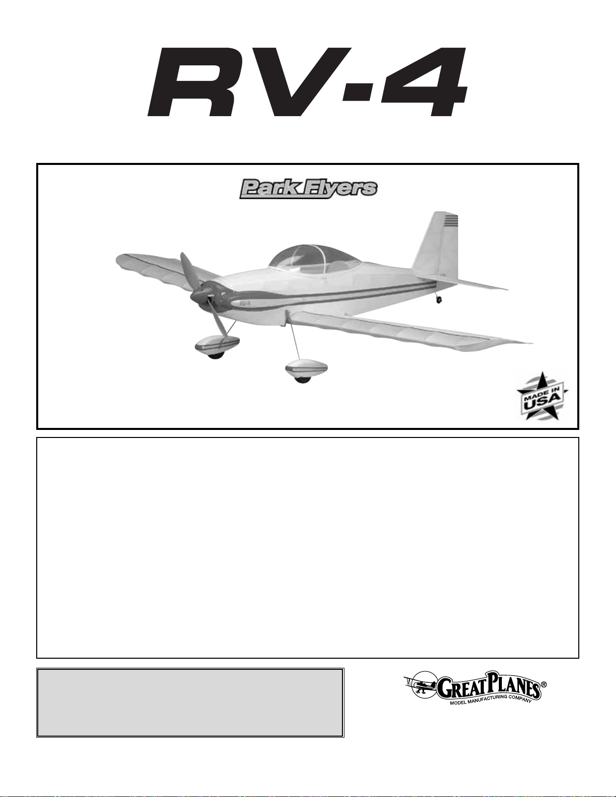
1. The easiest way to cut balsa sticks is with a single-edge
razor blade.To do so, position the stick over the plan, then
place the razor blade on the stick where you wish to cut it.
Press down lightly on the razor blade to mak e a mark where
the stick is to be cut.
2.Take the stick off the plan and cut it over a cutting mat or
a scrap piece of wood
(Okay, if you’re careful you could go
ahead and cut the stick right over the plan, but if y ou do , y ou
may cut through the plan protector, allowing the CA to soak
through and glue the structure to the plan)
.
3. Because of the small balsa sticks used in the tail, small
T-pins may be used to hold the sticks to your building board,
but only where necessary. Use small T-pins (HCAR5100)
or small straight pins found in craft stores.Do not stick pins
into the sticks near the ends, or the wood may split.
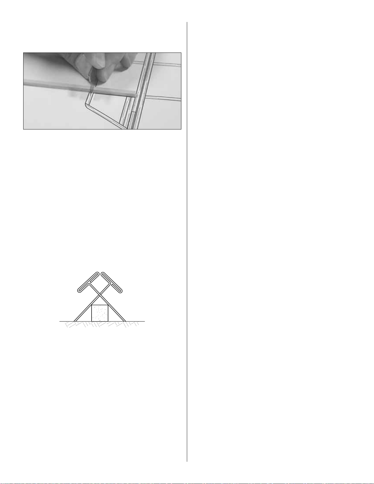
4. If you have difficulty with the T-pins splitting the small
sticks, an alternate method is to use the “crossed-pin”
technique. Insert the T-pins into the building board in a
crisscross fashion to hold the sticks to the plan.
5. Only a small amount of CA should be used to glue the
parts together. Use the included CA applicator tips to
control and pinpoint the amount of CA that comes from the
bottle. When the tip becomes clogged, cut the tip off and
continue. In addition to adding unnecessary weight, excess
CA is difficult to sand.If you require additional CA tips, order
number GPMR6033 (5).
6.When applying CA, be careful not to glue your fingers to the
structure. In the process of
un-sticking
your fingers you can
inadvertently damage the structure, thus requiring repairs and
adding weight
(not to mention the aggravation!)
.
7.Sanding requires a light touch to avoid damage.We found
the best method for sanding is to use light strokes in the
direction of the longest sticks. Be certain the sandpaper is
thoroughly bonded to the bar sander.Lifted edges will catch
the structure, causing damage.Use medium-grit sandpaper
such as 120 or 150-grit.
8. One of the best ways to insure a lightweight model is to
proceed slowly and build neatly. Good glue joints with minimal
adhesive are stronger, lighter and have a better appearance
than poor-fitting joints with too much CA.Of course, you should
take this approach with all of your projects!
9.Work over a flat surface .Cover the plan with Great Planes
Plan Protector™(GPMR6167) or wax paper so the parts will
not adhere to the plan.
7
Page 8
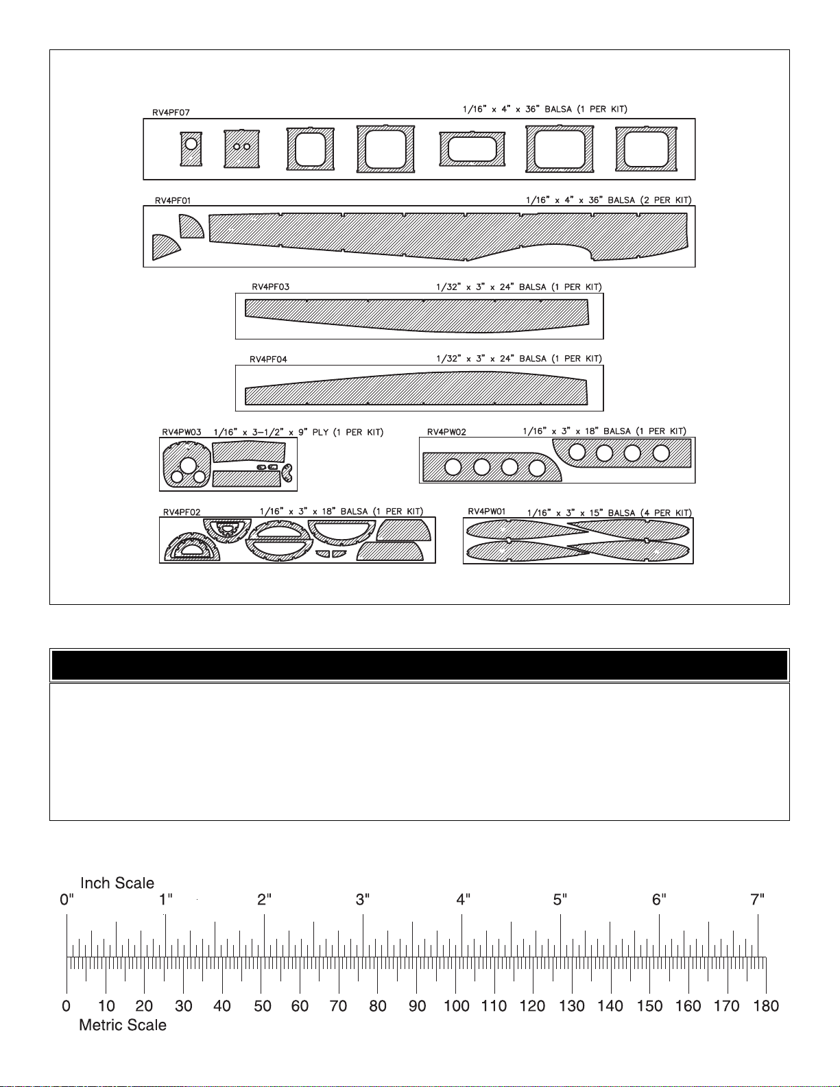
8
DIE-CUT PATTERNS
1/64" = .4 mm
1/32" = .8 mm
1/16" = 1.6 mm
3/32" = 2.4 mm
1/8" = 3.2 mm
5/32" = 4.0 mm
3/16" = 4.8 mm
1/4" = 6.4 mm
3/8" = 9.5 mm
1/2" = 12.7 mm
5/8" = 15.9 mm
3/4" = 19.0 mm
1" = 25.4 mm
2" = 50.8 mm
3" = 76.2 mm
6" = 152.4 mm
12" = 304.8 mm
18" = 457.2 mm
21" = 533.4 mm
24" = 609.6 mm
30" = 762.0 mm
36" = 914.4 mm
METRIC CONVERSIONS
Page 9
❏ 1. Unroll the plan sheets. Re-roll them inside-out so they
will lie flat. Place the fin/rudder portion of the fuse plan over
your flat building board, then cov er it with Great Planes Plan
Protector or wax paper so glue will not adhere to the plan.
Note: The bottom of the fin is difficult to see on the fuselage
plan. A separate drawing of the fin is located on the wing
plan and may be more useful for building the fin.
❏ 2.Find the four hardest 1/8" x 1/4" x 24" [3.2 x 6.4 x 610mm]
balsa sticks and set them aside for use as the wing spars.
❏ 3. Build the fin and rudder framework from two 1/8" x
1/4" x 24" [3.2 x 6.4 x 610mm] balsa sticks.Hint: Start with
the longest pieces first. If you accidentally cut one piece too
short, use it for a shorter piece somewhere else, thus
minimizing wasted material.
❏ 4. Add the fin and rudder ribs and diagonal braces
from two 1/8" x 1/8" x 24" [3.2 x 3.2 x 610mm] balsa sticks.
❏ 5. Remove the fin and rudder from the plan. Use a bar
sander with 150-grit sandpaper to carefully sand both sides
of the fin and rudder flat and even. Round the corners as
shown on the plan.Refer to the Expert Tip that follows, then
round the leading edge, top of the fin, trailing edge and top
of the rudder.
❏ 6. Sand a bevel on the leading edge of the rudder as
shown in the cross-section on the plan.
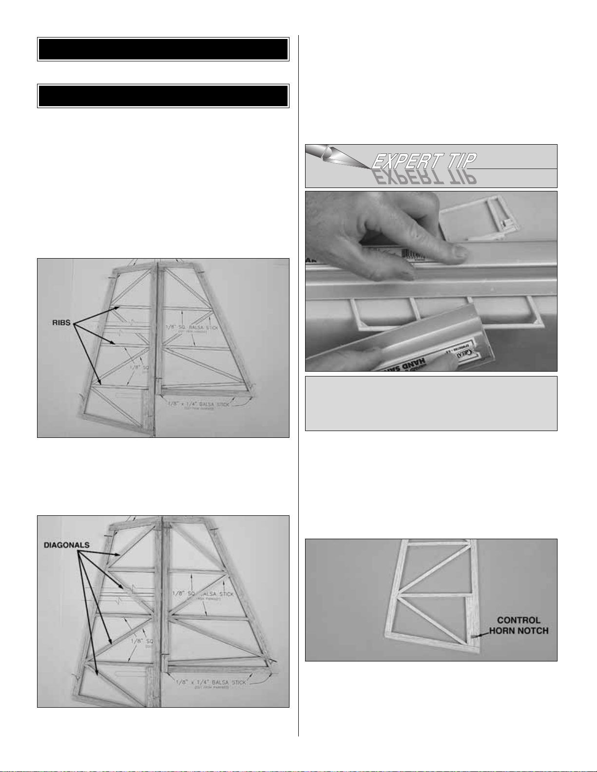
❏ 7. Use a #11 blade to cut the notch in the rudder where
shown on the plan for the laser-cut 1/16" [1.6mm] plywood
control horn. The control horn will be installed into the
notch on the right side of the r udder, but do not glue it into
place until the pushrods are installed during
“Hook Up the
Controls.”
The rudder control horn has an “R” printed on it.
To round the edges of the tail pieces, place one of them
on your workbench so the edge you are rounding extends
just beyond the edge of the bench. Use a bar sander to
hold it down. Use another bar sander to do the sanding.
BUILD THE T AIL SURF A CES
BUILDING INSTRUCTIONS
9
Page 10
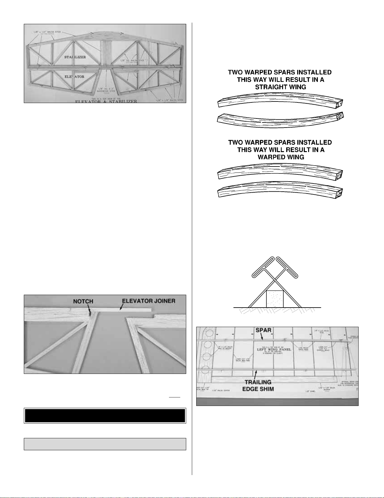
❏ 8.Build the stab and elevators from five 1/8" x 1/4" x 24"
[3.2 x 6.4 x 610mm] and two 1/8" x 1/8" x 24" [3.2 x 3.2 x
610mm] balsa sticks. Be sure to notch the leading edge of
both elevators where the bass w ood joiner stic k goes.Do not
join the elevators with the 1/8" x 1/8" x 3" [3.2 x 3.2 x 76mm]
basswood stick until instructed to do so.
❏ 9. The same as you did the fin and rudder, remove the
stab and elevators from the plans, sand the stab and
elevators flat and even, then round the corners where
shown on the plan.Round the tips of the stab and elevators .
Round the leading edge of the stab and the trailing edge of
the elevators. Bevel the leading edge of both elevators as
shown in the cross-section on the plan.
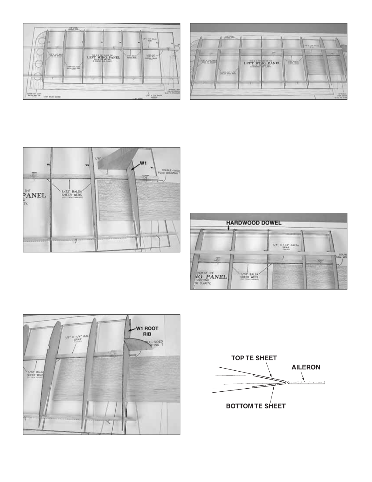
❏ 10. Use a #11 blade to cut the notch in the left elevator
where shown on the plan for the laser-cut 1/16" [1.6mm]
plywood control horn.The control horn will be installed into
the notch on the bottom of the left elevator, but do not glue
it into place until the pushrods are installed during
“Hook
Up the Controls.”
❏ 11.Use a bar sander with 150-grit sandpaper to bevel the
1/8" x 1/8" x 3" [3.2 x 3.2 x 76mm] basswood elevator
joiner to match the leading edge of the elevators.
❏ 12. Pin both elevators to the plan upside-down. Check the
fit of the elevator joiner and trim if necessary. Use medium CA
to securely glue the elevator joiner to the left elevator only
.
Start by building the left wing panel first so your progress
matches the photos.
❏ ❏ 1. Cover the left wing panel plan with Great Planes
Plan Protector or wax paper.
❏ ❏ 2. Find the four hardest 1/8" x 1/4" x 24" [3.2 x 6.4 x
610mm] balsa sticks you set aside earlier. Match the balsa
main spars so any warps will counteract each other.
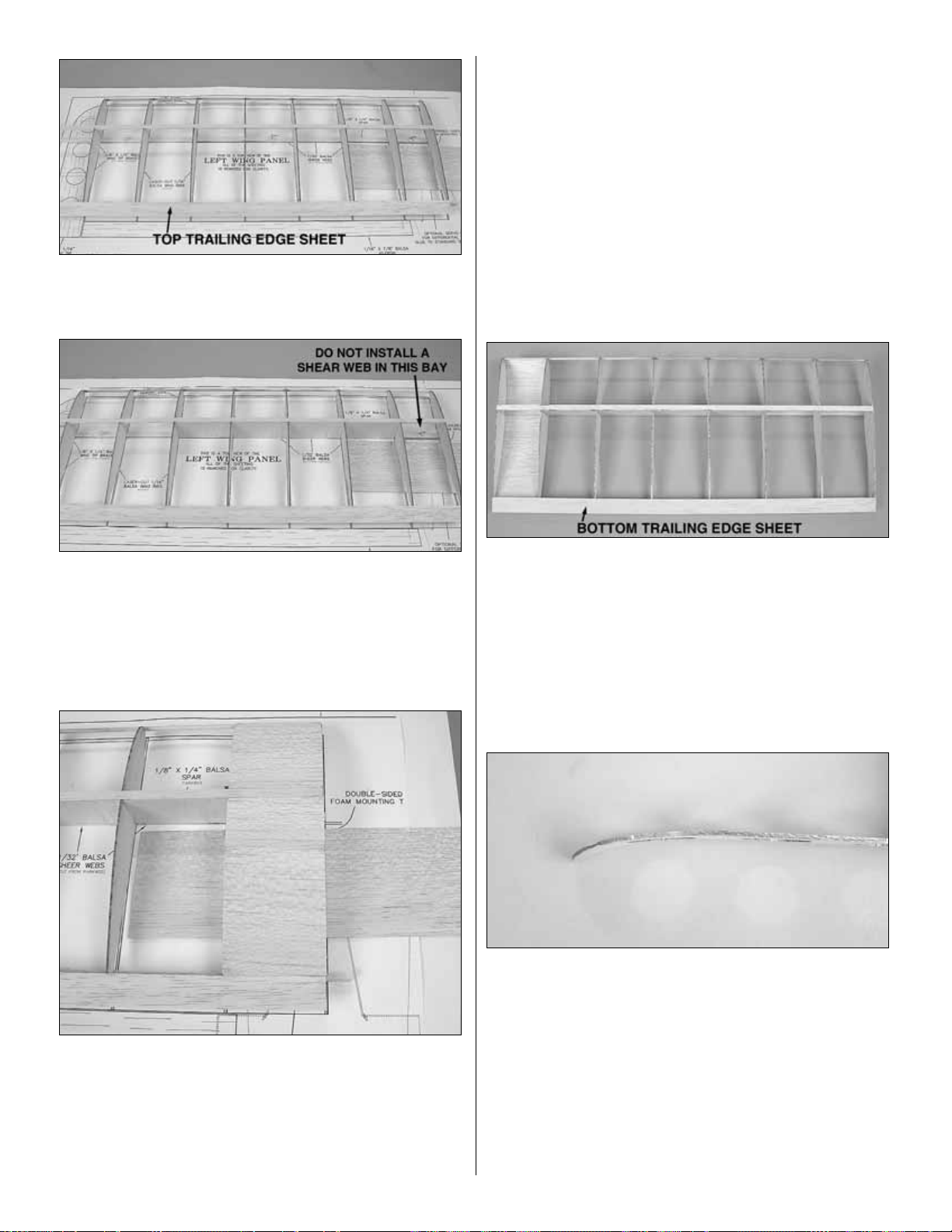
❏ ❏ 3. Pin one of the main spars in position over the plan,
aligning one end of the main spar with the outside edge of
the root rib W-1.
❏ ❏ 4. Pin the 1/8" x 3/8" x 24" [3.2 x 9.6 x 610mm] balsa
trailing edge shim in position over the plan, aligning the aft
edge of the stick on the dashed line. The shim should be
standing up with the 1/8" [3.2mm] edge on the table.
Build the Wing Panels
BUILD THE WING
10
Page 11
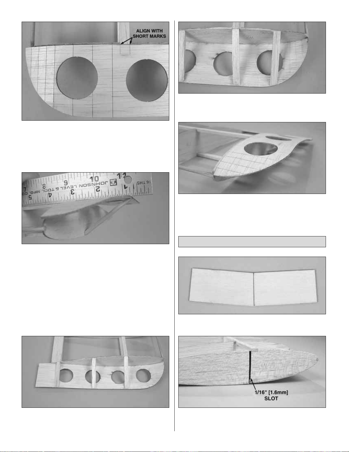
❏ ❏ 5. Starting at the wing tip, glue six laser-cut 1/16"
[1.6mm] balsa W2 ribs over the main spar, perpendicular to
the building board.Important: Pin the rear of the ribs firmly
to the TE shim.
❏ ❏ 6. Temporarily place a sheet of 1/32" [0.8mm] balsa
sheeting on the plan 1/4" [6.4mm] aft of the spar as shown
in the above photo. This will space the W1 ribs properly on
the spar. Glue a laser-cut 1/16" [1.6mm] balsa W1 rib in
place over the main spar as shown in the photo.
❏ ❏ 7. Position a W1 root rib in place over the main spar.
Use the die-cut 1/16" [1.6mm] dihedral gauge to set the rib
at the proper angle before gluing it to the main spar.
❏ ❏ 8.Position the top 1/8" x 1/4" x 24" [3.2 x 6.4 x 610mm]
balsa main spar in the rib notches with one end flush with
the outside edge of the W1 root rib. Glue the spar to all of
the ribs except the W1 root rib .Make sure all ribs, except the
root rib, are perpendicular to the table as you glue each rib
to the top spar.
❏ ❏ 9.Using the dihedral gauge, check that the root rib is still
at the correct angle. Glue the root rib to the top main spar.
Note: Save the dihedral gauge to set the angle of F5A.
❏ ❏ 10. Cut one of the 1/8" x 24" [3.2 x 610mm] hardwood
dowels to length so that it fits in the notches at the front of
the wing ribs, from the root to the tip rib. Glue the dowel to
the ribs.
❏ ❏ 11.Locate a 1/32" x 3/4" x 24" [.8 x 19 x 610mm] balsa
sheet.The sheet should fit in the notches at the trailing edge
of the wing ribs.When the wing is complete, it will blend with
the bottom trailing edge sheet when it is installed later.The
above sketch shows how the completed assembly will look.
11
Page 12
❏ ❏ 12. Glue the top trailing edge sheet to the top of the
wing ribs.
❏ ❏ 13. From a 1/32" x 3" x 15" [0.8 x 76 x 380mm] balsa
sheet, cut and glue shear webs, with the grain running
vertically , to the top and bottom spars in the locations shown
on the plan. It is not necessary for the shear webs to be
glued to the ribs at this time, but make sure they are glued
securely to the wing spars. Do not install shear webs in
the rib bay between the W1 ribs.
❏ ❏ 14. From a 1/32" x 3" x 15" [0.8 x 76 x 380mm] balsa
sheet, cut pieces to make the top center sheeting to fit
between the wing spar and trailing edge sheet and between
the wing spar and the leading edge dowel.Remove any pins
that may be under the area to be sheeted. When satisfied
with the fit, apply medium CA to the top of the W1 ribs and
press the sheeting in place.
❏ ❏ 15. Carefully sand the top center sheeting flush with
the wing spar, leading edge dowel and trailing edge sheet.
❏ ❏ 16. Remove the wing from your building board and
carefully sand off any glue blobs. Cut and sand the wing
spars, leading edge and trailing edge sheeting flush with the
wing tip rib and root rib.
❏ ❏ 17. Reinforce any glue joints that look weak. Glue the
shear webs to each rib. Remember, use glue sparingly to
minimize weight gain.
❏ ❏ 18. Glue a 1/32" x 3/4" x 24" [.8 x 19 x 610mm] balsa
bottom trailing edge sheet to the bottom of the wing ribs
and to the top trailing edge sheet.Trim the sheet even with
the tip and root ribs.
Before proceeding, read steps 19 through 25 to become
familiar with how the wing tip will be installed.
❏ ❏ 19.Prepare the laser-cut 1/16" [1.6mm] balsa wing tip
by carefully bending the forward part of the tip along the
embossed lines.You must do this gently to avoid breaking
part of the tip off. Do not bend along the two short lines that
are used to align the tip with the top wing spar.
Caution: On the left wing tip the embossed lines should be
on top of the wing tip. On the right wing tip the embossed
lines should be on the bottom of the wing tip. Hold the tip
against the wing to determine which way to bend for the
wing tip you are doing!
12
Page 13
❏ ❏ 20.Align the two short embossed lines on the wing tip
with the top main spar. Spot glue the wing tip to the end of
the wing spar with a small drop of thin CA.
❏ ❏ 21. From a leftover 1/8" x 1/4" [3.2 x 6.4mm] balsa
stick, cut a wing tip brace 2-1/4" [57mm] long. Bevel the
ends of the brace to fit the wing tip as shown in the photo
above. A straightedge can be used along the top spar to
hold the wing tip even and level with the top of the wing.
When satisfied with the fit, glue the brace in place. Hint:
First spot glue the brace to the W2 rib, then glue the end of
the brace to the wing tip while using the straightedge to hold
the wing tip level.
❏ ❏ 22. Glue the rear of the wing tip to the top edge of rib
W2. Make two more wing tip braces and glue them in place
where shown on the plan.
❏ ❏ 23. Glue the front of the wing tip to the top edge of rib
W2. Make one more wing tip brace and glue it in place
where shown on the plan.
❏ ❏ 24.Use a sanding block and 150-grit sandpaper to blend
the wing tip, wing tip braces and the W2 rib together smoothly.
❏ 25. Return to step 1 and build the right wing panel.
Remember! Build it over the right wing plan.
❏ 1. Draw a centerline on the laser-cut 1/16" [1.6mm] ply
dihedral brace.
❏ 2. Using a razor saw and hobby knife, carefully cut a
1/16" [1.6mm] slot in root rib W1, just behind the main spar,
on both wing panels.Test fit the dihedral brace in each slot.
Join the Wing Panels
13
Page 14

❏ 3.Test fit the wing halves together.With one wing half flat
on your building board, block-up the wing tip of the other
wing half so that it is 2-5/8" [67mm] off of your building
board. Use a bar sander to sand the center joint as
necessary until the wing halves fit together without any gap.
Note: Do not be concerned if your wing does not have
exactly 2-5/8" [67mm] dihedral. No adjustment is needed if
it is within 1/4" [6.4mm].
❏ 4. When satisfied with the fit, glue the ply dihedral brace
into the left wing panel with medium CA. Be sure the
dihedral brace is securely glued to the two main spars.After
the CA has hardened, tack-glue the right wing panel to the
ply dihedral brace with a small drop of thin CA. Do not glue
the root ribs together yet. With one wing panel flat on your
building board and the wing tip of the other wing half
blocked up as before, check that you have the same
measurement as in the above step. When satisfied with the
fit, wick more thin CA along the dihedral brace, securely
gluing it to both main spars in the right wing panel.
❏ 5. Align the trailing edges and glue them together with thin
CA. Glue the root ribs together from the spar to the trailing
edge by wicking thin CA between them. Glue the leading
edges and the rest of the root ribs together with thin CA.
❏ 6.Sand the leading and trailing edges of the wing joint flush.
❏ 7. Sheet the bottom of the center-section with a 1/32" x
3" x 15" [0.8 x 76 x 380mm] balsa sheet. If you are careful,
this can be done as a continuous strip across the full width
of the center-section, as shown in the above photo.
❏ 8. Fill any dings and uneven areas on the wing with light
weight balsa filler. Sand the wing smooth in preparation
for covering.
❏ ❏ 1. Using the drawings on the wing plan, follow the
procedure below to make a right aileron torque rod from
one of the .030" x 20" [.76 x 508mm] wires.
❏ ❏ A. Cut 1" [25mm] from one end of the .030" x 20" [.76
x 508mm] wire and clamp it in a vise.Make a loop near one
end of the remaining wire by pulling it around the wire
clamped in the vise.
❏ ❏ B .Cut the excess wire from the loop, then use the dra wing
on the plan to make the next bend as shown in the photo.
Build the Ailerons
14
Page 15

❏ ❏ C. Locate one of the 1/16" x 12" [1.6 x 305mm]
aluminum tubes. Cut two 9/16" [14mm] aileron torque rod
bearings from the tube.De-burr the holes in the tube with a
#11 knife blade. Install one of these pieces on the wire.
Make the final bend, then cut the wire to the length shown
on the plan. Be cer tain the horizontal portion of the torque
rod, that goes into the aileron, is perpendicular to the
vertical portion of the rod.
Remember: When you make the left torque rod, the bends are
in different directions and the length will be 1-1/8 [28.5mm].
❏ ❏ 2.Cut one of the 1/16" x 7/8" x 17" [1.6 x 22 x 430mm]
balsa ailerons to the length shown on the wing plan. Drill a
#68 (or 1/32") [0.8mm] hole into the leading edge of the
aileron where shown on the plan for the aileron torque rod.
❏ ❏ 3. Cut a notch in the leading edge of the aileron
between the hole you drilled and the end to accommodate
the torque rod. Glue the torque rod to the aileron with
medium CA.
❏ 4. Retur n to step 1 and make the left aileron torque rod
and aileron the same way.
Refer to these photos for the following five steps.Note:
You may want to delay the following steps until after the
model is covered.
❏ 5. Temporarily tape both ailerons to the wing.
❏ 6. Glue the laser-cut 1/16" [1.6mm] ply servo horn to the
plastic servo horn included with your servo.With this servo
horn, the ailerons will travel up more than down, reducing
adverse yaw, which is the tendency for the nose of the
model to turn away from the direction of banked turns.
❏ 7. Cut the top sheeting for the aileron servo, so that the
servo can be mounted to the left side of the center rib, aft of
the wing joiner and spar.
❏ 8. Clean the aileron servo case with a tissue dampened
with alcohol or other suitable solvent. Mount the aileron
servo to the side of the center rib with double-sided foam
mounting tape (GPMQ4440, not included).
Note: For a more secure bond to the wing rib, first coat the
rib with a thin layer of medium CA where the tape will be
applied.Sand the hardened CA to remove any irregularities.
❏ 9. Use the remainder of the .030" [.76mm] wire you used
for the torque rods to make the ailer on pushr ods.Note that
the pushrods are connected to the torque rods with a
“Z-bend” on both ends. If you do not have Z-bend pliers, or
do not know how to make a Z-bend with regular pliers, f ollo w
the procedure below. (For clarity, larger wire than was
supplied with this kit was used in the photos.)
❏ A. Make the first 90° bend near one end of the wire.
❏ B. Hold the wire in the pliers as shown.
15
Page 16

❏ C. Make the second 90° bend downward.
❏ D.Make the final 90° bend (twist) upward to form the “Z.”
❏ E. Cut the excess wire near the end.
Note: This procedure does not work for all types of wire, but
will work on the thin music wire supplied with this kit.
❏ 10. Connect the aileron ser vo to the aileron torque rods
with the pushrods you just made.
❏ 11. If you need to tweak the linkage slightly to center the
ailerons, you can make a slight bend in the aileron torque rod.
❏ 12. After the model is covered, glue the aileron torque
rod bearings to the trailing edge of the wing with medium
CA. Coat the torque rod with a film of oil or Vaseline®to
prevent CA from adhering to the torque rod.
❏ 1. Glue a 1/8" x 1/8" [3.2 x 3.2mm] balsa stick to the top
and bottom on one side of formers F2 to F8. Note: The side
with the sticks on it is now the front.
Frame the Sides
BUILD THE FUSELAGE
16
Page 17

❏ 2. Use thin CA to glue the die-cut 1/16" [1.6mm] left and
right fuselage top deck pieces together. Hold the pieces
together tightly while applying CA glue to the joint a couple
of inches at a time, wiping excess CA from the joint before
it hardens. Lightly sand the top deck smooth.
❏ 3. Use a straightedge and a hobby knife to trim the front
edge of one of the die-cut 1/16" [1.6mm] balsa fuselage
sides along the cut line. Mar k the inside of that fuse side
with an “R,” designating it as the right side. Note: The cut
line is not straight and angles about halfway down the side.
❏ 4. There are die-cut markings for the pushrod exit slots
on the rear of the fuselage sides.Cut out the lower rear slot
on the right fuselage side. Cut out the upper forward slot
on the other fuselage side, which now becomes the left
side. Note: The marked slots can be difficult to see. Cut the
slots according to the dimensions shown in the above photo .
❏ 5. Cover the bottom view of the fuse plan with Plan
Protector or wax paper. Pin the die-cut 1/16" [1.6mm] balsa
fuselage top deck over the bottom view of the fuselage plan.
Important: The front of the top deck should be aligned with
the rear of F1.The fuselage sides will extend 1/16" [1.6mm]
forward of the top deck.
❏ 6. Fit former F4 and the fuse sides to the fuse top.When
satisfied with the fit, glue F4 to the fuse top and sides.Note:
Make certain the right fuse side is on the right, and the left
fuse side is on the left (Remember, you are building the
fuselage upside-down.)
❏ 7.Working forward one former at a time, glue formers F3
and F2 to the fuse top and sides.
17
Page 18

❏ 8. Working aft one former at a time, glue formers F5, F6
and F7 to the fuse top and sides. Glue the fuse sides to the
fuse top.
❏ 9. Glue former F8 into position between the fuselage sides.
❏ 10.Glue the laser-cut 1/16" [1.6mm] ply landing gear mount
to the fuselage where shown on the side view of the plan.
❏ 11. Use a sheet of 1/32" x 3" x 15" [0.8 x 76 x 380mm]
balsa to sheet the bottom rear of the fuselage. Start at
former F5 and cut and glue only the first two pieces. The
remainder of the sheeting will be installed after the servos
are installed.
❏ 12. Remove the fuselage from the plan. Reinforce any
glue joints that look weak.Lightly sand the fuselage smooth.
❏ 13.Cut two 1" [25.4mm] pieces from a leftover 1/8" x 1/4"
[3.2 x 6.4mm] balsa stick. Glue a piece to each side of the
fuselage on top of the ply landing gear mount.
❏ 1. Locate the laser-cut 1/16" [1.6mm] ply former F1.
Draw a line across the top of the former on the front, as
shown in the photo. Note that the hole for the gearbox is
offset to the right as seen in the above photo.
❏ 2. Cut three 1/2" [13mm] pieces from a leftover 1/8" x 1/4"
[3.2 x 6.4mm] balsa stick.Glue a piece over each of the screw
holes on the rear of F1. Position them as shown in the photo.
Finish the Fuselage
18
Page 19

❏ 3. Cut four 1" [25.4mm] pieces from a leftover 1/8" x 1/4"
[3.2 x 6.4mm] balsa stick.
Before proceeding, read steps 4 thru 9.This will give you a
better understanding of how to proceed.
❏ 4. Check the fit of former F1 to the front of the fuselage.
The top deck should end 1/16" [1.6mm] aft of the front
edges of the fuselage sides. With F1 in place, the top deck
should be against the rear of F1. Note: It may be necessary
to trim the fuse sides to match the width of the firewall.
❏ 5. Glue F1 to the upper part of the left fuselage side.The
line drawn across the top of F1 should be aligned with the
top of the fuselage side. Align F1 accurately with the slope
on the upper part of the fuselage side.The lower part of the
fuselage side angles forward slightly. Do not glue F1 to the
lower part of the fuselage side. Glue the top deck to the
fuselage side as well.
❏ 6. Glue one of the 1" [25.4mm] strips that you cut earlier
to the fuselage side and the rear of F1.
❏ 7. Glue F1 to the upper part of the r ight fuselage side.
The line drawn across the top of F1 should be aligned with
the top of the fuselage side. Make sure F1 is aligned
accurately with the slope on the upper part of the fuselage
side. Do not glue F1 to the lower part of the fuselage side.
Glue another 1" [25.4mm] strip to the right fuselage side
and the rear of F1.
❏ 8. Prepare two of the 1" [25.4mm] balsa strips as shown
in the photo. Sand a curve along one side to match the
curve of the lower part of F1. Sand an angle along the side
of this curve. Study steps 9 and 10 to get a better idea of
how the strip should be shaped. This piece is fitted into
place in step 10, but it will help to have the part sanded to
shape first.
The lower front of the right fuselage side will now be glued
to the curved part of F1. The fuselage side must first be
wetted for it to bend around this curve.We have found the
best solution for this is 70% isopropyl alcohol (rubbing
alcohol), which will soak in rapidly and dry quickly. This
looks difficult, but if you proceed as instructed it works well.
19
Page 20

❏ 9.Wet the outside of the sheeting where it curves around
the bottom of F1. Slowly bend the fuselage side along the
curve. If it begins to crack, moisten the area with more
alcohol. Once you get the wood to bend along the curve,
soak some thin CA into the joint between the right fuselage
side and F1. Continue to hold pressure on the joint, even
after the CA has hardened.
Note: Put some wax paper or plan protector between your
thumb and the fuselage side so you don’t glue yourself to
the model.
Caution: Do not squeeze the joint too tightly or you will
break the fuselage side.
❏ 10.While still holding the joint tightly, fit and glue the strip
you prepared in step 8 to the back of F1, along the side of
the fuselage. It does not have to fit tightly. Soak some thin
CA onto the area, keeping the strip in place. After the thin
CA hardens, fill any gaps with medium CA. Do not release
pressure on the joint until after the medium CA has fully
hardened. CA accelerator will speed the process.
❏ 11. In the same way, glue the left fuselage side to former
F1.Before doing so, glue the die-cut reference cut lines with
some thin CA. As you glue the side in place, it may crack at
the bottom of the cut line. Once the side is glued in place
any cracks can be sanded smooth and filled with lightweight
balsa filler.
❏ 12. Carefully sand the fuselage sides even with the front
of former F1. Do not push the sandpaper back and forth
across the joint.Rather, push the sandpaper across the joint
towards the center of the former. Be careful not to snag the
opposite fuselage side.
❏ 13. Cut six 2" [51mm] sticks from the 1/8" x 3/8" [3.2 x
9.6mm] balsa stick.Working one at a time, glue three sticks
to the inside of each fuse side to create a gluing surface for
the bottom sheeting.
20
Page 21

❏ 14. Sand the sticks flat so that the bottom sheeting can
be glued in place.
❏ 15. Using the 1/16" x 3" [1.6 x 76mm] balsa sheet, sheet
the bottom front of the fuselage. Start by gluing a sheet
beginning at the ply landing gear mount.
❏ 16. Sand the contour of the fuselage front to blend into
former F1. Fill any gaps with lightweight balsa filler.
❏ 17.Place the fuselage upside-down over the bottom view
of the plan. Mark the location of formers F2A, F3A, F4A,
F5A, F6A and F7A on the left and right fuselage sides.
Transfer the marks to the top deck of the fuselage. Note on
the side view that formers F4A and F5A are not located over
F4 and F5.
❏ 18. Glue the die-cut 1/16" [1.6mm] balsa formers F2A
thru F8A to the fuselage top deck. Formers F2A, F3A, F6A,
F7A and F8A are glued perpendicular to the top deck. Use
the die-cut 1/16" [1.6mm] balsa F3A gauge to establish the
correct angle of F4A. Use the die-cut 1/16" [1.6mm]
dihedral gauge to set the angle of F5A.
❏ 19. Using three 1/8" x 1/8" x 24" [3.2 x 3.2 x 610mm]
balsa sticks, cut, fit and glue the stringers to the forward part
of the fuselage. Star t with the bottom stringer, which goes
from F1 to F5A. Use the remainder of this stick to do the
stringer above it. Use the third stick to do the top center
stringer, saving the remainder of the stic k f or the top stringer
on the aft part of the fuselage.
❏ 20. Using five 1/8" x 1/8" x 24" [3.2 x 3.2 x 610mm] balsa
sticks, cut, fit and glue the stringers to the aft part of the
fuselage. Start with the two bottom stringers on each side,
which go from F5 to the rear of F8.
21
Page 22

❏ 21. Use a leftover 1/8" x 1/8" [3.2 x 3.2mm] balsa stick to
reinforce the trailing edge of the fuse sides and where the
horizontal stab will be mounted. This will provide additional
gluing area.
❏ 22. Temporarily pin the hor izontal stab to the fuselage,
making sure it is centered.
❏ 23.Hold the fuselage on the wing and check that the stab
is level with the wing.Lightly sand the stab mount as needed
to make it level with the wing.
❏ 24. Glue a filler stick cut from leftover 1/8" x 1/4" [3.2 x
6.4mm] balsa to the top of the fuselage, 3/16" [5mm] behind
the stab.Be careful not to glue the stab to the fuselage.
❏ 25.Tack glue a leftover 1/8" x 1/8" [3.2 x 3.2mm] balsa stic k
across the front of the stab saddle area of the fuse.
❏ 26. Tack glue a 1/8" x 1/8" [3.2 x 3.2mm] balsa stick
centered on top of the sticks glued in the last two steps.
❏ 27.Cut the 3/4" x 3/4" x 12" [19 x 19 x 305mm] balsa stick
in half, making two 6" [152.5mm] pieces.Tack glue these to
the sticks as shown.
❏ 28. Using a razor plane and progressively finer grades of
sandpaper, shape the fillet blocks until they blend into and
follow the contour of the fuselage.
❏ 29. Cut the fillet blocks and false stab/fin off the aircraft.
Remove the sticks used to represent the stab and fin.
22
Page 23

❏ 30. Being careful not to glue the stab or fin, glue the stab
fillets to the fuse using the fin and stab spacers. Note: The
stab and fin will be installed after the model is covered.
❏ 31.From a 1/8" [3.2mm] dowel, cut a 4-3/4" [120mm] rear
wing hold-down dowel and a 5-3/4" [146mm] front wing
hold-down dowel. Round the ends for a neat appearance.
❏ 32. Drill 1/8" [3.2mm] holes in the sides of the fuselage
for each dowel where shown on the plan and insert each
dowel into the fuselage.
Caution: If the rear dowel is too low, it will interfere with the
aileron pushrods. If the front dowel is too low, it will not
provide proper shock absorption for the landing gear.
❏ 33. Cut four 5/8" [16mm] long blocks from a leftover 1/8" x
1/4" [3.2 x 6.4mm] balsa stick.Glue a block to the inside of the
fuselage side under each dowel end to reinforce the area.
Note: Remove the dowel first so you don’t glue the dowel
in place.
❏ 34. Glue the small laser-cut 1/16" [1.6mm] balsa braces
to the fuselage top deck midway between formers F4A and
F5A. These braces are used only to provide additional
support for the canopy and do not need to be even with the
fuselage sides or the stringer.
If you would like to b lend the leading and trailing edge of the
wing with the bottom of the fuselage, continue with step 36.
Otherwise, go to
“Install the Pushrods”
on page 24.
Adding these fairings will only add a slight amount of weight
to the model.
❏ 35. Cut a 3-3/4" [95mm] fairing strip from a leftover 1/8"
x 1/4" [3.2 x 6.4mm] balsa stick. Sand a taper on the ends
of the stick as shown in the above photo.
❏ 36. Glue the fairing strip to the bottom of the fuselage
behind the trailing edge of the wing.
23
Page 24

❏ 37. Blend the fairing strip to the fuselage bottom with
some lightweight balsa filler.
❏ 38. Using a leftover piece of 1/16" [1.6mm] balsa
sheeting, cut a piece 4-3/8" [111mm] long. Notch one side
of this piece as shown in the above sketch.
❏ 39. Place the piece on the leading edge of the wing,
against the fuselage. Mark the sheet where it needs to be
cut flush with the bottom of the fuselage.
❏ 40. Tack glue this filler strip to the leading edge of the
wing, being careful not to glue it or the wing to the fuselage.
Remove the wing and reinforce the glue joint.
❏ 41. Using a leftover piece of 1/32" [0.8mm] balsa sheet,
cut a piece 4-3/8" x 1-1/2" [111 x 38mm]. Glue this piece to
the filler strip and the bottom wing sheeting.
❏ 42. Use leftover 1/32" [0.8mm] balsa to cut, fit and glue
filler strips to the end of the sheeting.
For the following steps make sure the horizontal stab and
vertical fin are pinned in place on the fuselage.
❏ 1. Use a tissue dampened with denatured alcohol or
other suitable solvent to clean the servo cases so the
mounting tape will adhere.Use double-sided foam mounting
tape (GPMQ4440, not included) to mount the elevator and
rudder servos to the fuse sides where shown on the plan.
Install the Pushrods
24
Page 25

❏ 2. Thoroughly clean the remaining .030" x 20" [.76 x
508mm] wire with alcohol or similar solvent, then scuff it with
320-grit sandpaper so glue will adhere.
❏ 3.Cut 5" [127mm] from the wire. Make a “Z” bend on one
end and a slight bend on the other end. See the drawing on
the fuselage plan.This is a control horn pushrod end.
❏ 4. Use pliers to inser t this pushrod end 1" [25.4mm] into
a 1/16" x 12" [1.6 x 305mm] aluminum pushrod tube. Use
thin CA to glue the pushrod end into the pushrod tube.
❏ 5.Make another pushrod end from a 4-1/4" [108mm] wire
just the same as the first and insert it into the other end of
the pushrod tube, but do not glue it in. See the drawing on
the fuselage plan.This will be the elevator pushrod.
❏ 6. Make sure the pushrod end that is not glued into the
tube fits tightly and will not easily slide in and out. It will be
permanently glued in after the model has been set up and
the exact length of the pushrod has been determined.
Refer to this photo for the following four steps. Note:
The photo shows how the completed installation will look.
❏ 7. Cut a slot in the fuselage at the rear of the horizontal
stab for the 1/8" [3.2mm] elevator joiner, installed in the left
elevator. Insert the joiner in the slot and check that the
elevator will move freely once installed. Temporarily hinge
the left elevator to the stab using clear cellophane tape.
❏ 8. Insert the elevator pushrod into the fuse through the
slot in the left side. The pushrod end that is not glued into
the tube should be at the servo end.
❏ 9. Connect the front of the pushrod to the ser vo arm, then
mount the servo arm to the elevator servo. Connect the other
end of the pushrod to the outer hole in the elevator control horn,
then insert the control horn into the slot in the elevator.
❏ 10. Slide the pushrod end in or out of the pushrod tube
until the elevator is centered when the servo is centered.
❏ 11. Make the rudder pushrod and join the rudder to the
fin the same way. The r udder pushrod should be inserted
into the inner hole of the rudder control horn.
Note:The photo shows how the completed installation will look.
❏ 12. The pushrods should be braced at the locations
shown on the plan. This photo shows the bracing installed
25
Page 26

just forward of F6. Use a leftover piece of 1/8" x 1/4" [3.2 x
6.4mm] balsa for the main brace. Cut notches in the brace
where the pushrods cross it. Hold the pushrods in the
notches with leftover 1/8" x 1/8" [3.2 x 3.2mm] balsa. Be
careful not to glue the pushrods to the braces.
❏ 13. In a similar manner, install pushrod bracing where
shown on the plan at the rear of the fuselage. This photo
shows the bracing between F7 and F8.
❏ 14. Sheet the bottom rear of the fuselage with the
remaining 1/32" [0.8mm] balsa sheeting.
❏ 15. Remove the servo arms from the top of the servos.
Pull the pushrods into the fuselage so that the rear ends do
not extend out of the fuselage.
❏ 16.Remove the stab and fin from the fuselage.Reinforce
the glue joints of stringers that were tack glued into place.
Sand the stringers even with F4 and F5. Sand all str ingers
to a smooth contoured shape. Sand the sheeting even with
the fuselage sides.
❏ 1. If you haven’t done so already, sand all par ts of the
model smooth with 320-grit, then 400-grit sandpaper.
❏ 2. Use compressed air (be careful!), a dust br ush or a
tack cloth to remove balsa dust from the model.
❏ 3. Determine what material you will be covering the
model with. If using Top Flite EconoKote, the model is ready
to cover. If using Coverite CoverLite, coat the areas to be
covered with Coverite Balsarite Fabric Formula
(COVR2500). Be certain you use the fabric formula for
CoverLite, and not the formula for regular film covering.
❏ 4. Follow the suggested covering sequence to cover
the model.
Important: Do not shrink the covering until both sides of
each part are covered.This will reduce the tendency for the
surfaces to twist.
Tail Surfaces:
❏ 1.The bottom, then the top of the stabilizer
❏ 2.Bottom, then top of elevators
❏ 3.Fin
❏ 4.Rudder
Fuselage:
❏ 1.Bottom
❏ 2.Sides and top
Wing:
❏ 1.The bottom of the wing
❏ 2.Top of the wing
❏ 3.Ailerons
Note: It may be easier to cover the wing tips separately,
after the rest of the wing has been covered.
❏ 1. After all the tail pieces are covered, inspect the stab
and fin for twists. If necessar y, lightly twist the part in the
opposite direction and apply heat to the covering until you
can get it flat.
An important characteristic of most air planes is their ability
to resist stalling, or to stall gently. Simply stated, a stall is
when the wing no longer produces lift–basically the model
quits flying until it regains airspeed. A stall can occur when
attempting to climb too rapidly, or when the model r uns out
of airspeed (such as when trying to land too slowly). One
way to prevent or delay a stall is to add “washout” to the
wing. Washout is an upward twist at both wing tips, so that
the trailing edge is higher than the leading edge. If the
trailing edges are raised slightly, or are at a lower angle then
the rest of the wing, the outer portion of the wing will
continue to produce lift (fly) even though the rest of the wing
has quit flying, thus resisting a stall. Because the RV-4 Park
Flyer is designed to be light, it would be difficult to build this
required twist into the wing during construction. The
following procedure explains how to add washout, which is
common for lightweight structures such as this.
❏ 1. Start with the r ight wing panel. Holding the middle of
the wing in one hand, twist the trailing edge of the right wing
tip upward. The amount of washout to shoot for is 1/8"
[3.2mm], so begin by twisting about 1/2" [13mm] (because
the wing will “spring” par tway back to its original position
after re-shrinking the covering in the next step).
Add “Washout”
Suggested Covering Sequence
CO VER THE MODEL
26
Page 27

❏ 2. Note the wrinkles in the covering while holding the
wing.Have an assistant heat the covering on the top and the
bottom until the wrinkles disappear. Allow the covering to
fully cool before letting go.
❏ 3. Add washout to the left wing panel the same way.
❏ 4. Check the wing periodically to be sure the washout
remains. Twist and shrink the covering as necessary to
retain the washout.
❏ 1. Mount the wing to the fuse with two #64 rubber bands
(when it’s time to fly the RV-4 Park Flyer, use four #64
rubber bands). Trim the front edge of the aft fuse bottom
sheeting and cut notches in former F5 to accommodate the
aileron torque rods. If you have to cut much of the former,
use a leftover 1/8" x 1/8" [3.2 x 3.2mm] balsa stick to cut and
glue a reinforcing piece behind F5.
❏ 2. Use a small pin to poke several holes through the
covering in the top and bottom of the stab where it will be
glued to the fuselage. These holes will absorb the CA that
will be used to glue the fin to the stab and will make for a
stronger glue joint.
❏ 3. Place the stab in the fuse, making sure it is centered
as shown in “A” = “A” in the photo above. Hint: If the
covering on the stab is transparent, align the sticks on both
sides of the center stick with the fuse.
❏ 4.View the model from the rear and see if the stab is le v el
with the wing as shown in “B” = “B.” If the stab is not level
with the wing, carefully sand the “high side” of the fuse until
you can get the stab to align.
❏ 5. Use a string or tape measure to align the stab. Put a
pin in the center of the top of former F1. Tie a loop in one
end of the string and place it over the pin. Put some tape
over the string with a mark on it. Swing the str ing from side
to side and adjust the stab as required until the stab is
aligned properly.
❏ 6. When satisfied with the alignment, glue the stab in
place with thin CA.
❏ 7. Inser t the vertical fin in the fuselage. Use a builders
square to get the fin perpendicular to the stab. Make sure
Join the Tail Surfaces
FINAL ASSEMBLY
Note: For a small, lightweight model such as the RV-4
Park Flyer, it is not critical to get exactly 1/8” [3.3mm] of
washout. However, it is important that
some
washout be
present in both wing tips. Do your best to achieve the
washout recommended, but don’t spend hours trying to
do so.A slight variance in both wing tips is acceptable, as
long as neither of the wing tips have any “wash-in.”
27
Page 28

the fin is aligned with the rear of the fuselage.Glue the stab
to the fuse with thin CA. The photo shows the rudder
installed on the fin, but your model will not have the rudder
installed yet.
❏ 8. Place the rudder over the plans and mark the location
of the tail wheel wire where it mounts on the rudder. Drill a
1/16" [1.6mm] hole in the leading edge of the rudder for the
wire. Notch the leading edge of the rudder for the wire to fit
into.Insert the tail wheel wire in the rudder and make sure it
is aligned correctly. Make sure the model will track correctly
on the ground with the rudder centered. Glue the tail wheel
wire into the rudder with thin CA.
❏ 1.Before proceeding, charge the motor battery (and your
transmitter if needed).When it’s time to set up the radio you
won’t have to stand by while the batteries are charging.
❏ 2.Cut the covering from the elevator and rudder pushrod
exit slots near the aft end of the fuse.Push the rear ends of
the pushrods out the slots in the rear of the fuselage.
Refer to this photo for the following four steps.
❏ 3. Install the left elevator on the fuselage. Insert the
elevator joiner in the slot behind the stab and check that the
elevator will move freely once installed. Hinge the left
elevator to the stab using clear cellophane tape as sho wn in
the sketch that follows.
❏ 4. Connect the front of the elevator pushrod to the servo
arm, then mount the servo arm to the elevator servo.Connect
the other end of the pushrod to the outer hole in the elevator
control horn, then insert the control hor n into the slot in the
elevator. Glue the control horn into place with thin CA.
❏ 5. Slide the pushrod end in or out of the pushrod tube
until the elevator is centered when the servo is centered.
❏ 6. Hinge the right elevator to the stab using clear cellophane
tape. Glue the 1/8" [3.2mm] elevator joiner to the right elevator
with thin CA. Make sure the left and right elevators are aligned
before gluing the joiner into place. Be careful not to glue the
joiner or the elevator to the stab or fuselage.
❏ 7. Install the rudder to the fin with clear cellophane tape.
The rudder pushrod should be inserted into the inner hole of
the rudder control horn.
❏ 8. If you have not done so already, attach the ailerons to
the wing with cellophane tape the same as you did the
elevators and rudder. Follow the instructions on page 14,
“Build the Ailerons”
for pushrod installation.
❏ 1. Install the supplied 3/4" [19mm] tail wheel on the tail
wheel wire. Hold it in place with a white nylon retainer.
❏ 2. Install the supplied 2" [51mm] wheels on the 3/32"
[1.6mm] wire landing gear. Secure the wheels with the
supplied wheel collars and set screws.
Mount the Landing Gear
Hook Up the Controls
28
Page 29

❏ 3. Mount the landing gear to the fuse with a #14 rubber
band on each side. Both rubber bands must be stretched
enough to wrap around the gear and dowel at least two times.
❏ 4. Cut four 1" [25.4mm] pieces from a leftover 1/8" x 1/8"
[32. x 3.2mm] balsa stick. Glue the pieces in front of and
behind the landing gear as shown in the photo.
Follow these assembly instructions for the Great Planes
ElectriFly motor and S-280 gear drive. If you are using
another type of gear drive and motor, follow the instructions
that came with the unit.
❏ 1. Use denatured alcohol or other solvent to clean the
motor shaft. Roughen the shaft with 320-grit sandpaper so
glue will adhere.
Note: If you are using the Great Planes ElectriFly S-370
motor, you should lightly file the knurling on the motor shaft
to make installation of the pinion gear easier. Wrap the
motor in a plastic bag to prevent metal filings from entering
the motor.
❏ 2. Apply a small amount of the green locking glue to the
motor shaft. Press the pinion gear onto the motor shaft using
a small hammer, base of a large screwdriver or something
similar.Depending on how tight the fit is, you may have to tap
the gear into place. While doing this, do not rest the base of
the motor on your workbench, but support the motor shaft with
a piece of hardwood. This way, the pressure applied to the
gear will not displace the armature in the motor.
Note: If you are using the Great Planes ElectriFly S-370
motor, it is easier to press the gear into place between the
jaws of a vise. Be careful not to damage the capacitors
installed on the back of the motor. Follow the instructions
supplied with the motor.
❏ 3. Press the motor by hand as far as it will go into the
gear drive unit.Draw a pencil line around the motor where it
aligns with the rear of the gear drive unit.Back the motor out
about 1/16" [1.6mm]. Spin the gear dr ive output shaft with
your fingers to insure that the gear drive and motor move
freely. If the fit of the motor in the gear dr ive is loose, use a
drop of CA to hold the motor in place.
Note:If you are using the Great Planes ElectriFly S-370 motor
the fit of the motor in the gear drive will be very tight.Carefully
use a slip joint pliers to install the motor in the gear drive.
Assemble the Gear Drive
29
Page 30

❏ 4. Connect the motor to the speed control. Guide the
speed control and wiring through the hole in F1. Mount the
gearbox to F1 with screws supplied with the gearbox.
Note: If you are installing a speed 400 size motor you will
need to enlarge the hole in F1 slightly. This can be easily
done with a rotary tool and a sanding drum.
❏ 1. Paint the cockpit area to suit your color scheme. We
used black, water-based paint.
2. Trim the pilot outlines from the fuselage plan and glue
them to a flat piece of foam, such as from a foam dinner
plate. Trim the assembly and paint the pilot as desired.
Mount the pilot to the cockpit floor with clear tape.
❏ 3. Trim the canopy to fit the cockpit area. We trimmed
ours even with the bottom edge of the canopy as close to
the base as possible, but you may want to leave a small lip
around the base.
❏ 4.Mount the canopy to the fuselage.This can be done by
taping the canopy to the fuselage with clear tape or by using
the supplied #2 x 3/8" [9.6mm] screws.
❏ 5. On our model, we used a screw at the front and rear
of the canopy and tape on the sides.
❏ 6.Cut the cowl from its plastic sheet as close to the base
as possible. Fit the cowl to the front of the fuselage. Mount
the prop adapter and the spinner back plate to the gearbox
output shaft. Position the cowl so it is centered on the
spinner back plate and tape it into place on the fuselage.
❏ 7. Cut the cowl cheeks from their plastic sheet, leaving a
small lip at the edges.
❏ 8.Fit the cowl cheeks to the model and tape them into place.
MOUNT THE CANOPY , COWL &
WHEEL PANTS
30
Page 31

❏ 9.Use four #2 x 3/16" [4.8mm] screws to hold the cowl in
place, two on each side of the cowl cheek. Use a 1/16"
[1.6mm] drill bit to drill the screw holes into the F1.
❏ 10. Mark the cowl cheeks and cowl to suit your trim
scheme. Remove them from the model and paint them as
desired. When you mount the parts back on the model, the
cowl cheeks can be glued into place with thin CA, being
careful not to glue the cowl.
The next two steps are very important for adequate cooling
of the motor.
❏ 11. Trim the bottom of the cowl to allow cooling air to
enter the cooling holes in former F1. This is especially
important if you are using the Great Planes S-280 or S-370
motor. Without adequate cooling, these motors can easily
overheat, greatly reducing their life span.
❏ 12. Cut an opening in the bottom of the fuselage for
heated air to escape.This hole should be at least 1-1/4" x 2"
[32 x 51mm].
❏ ❏ 13. Cut the right wheel pant par ts from their plastic
sheet, trimming them as close to the sheet as possible.
❏ ❏ 14. Remove the right wheel from the model. Fit the
wheel pant parts together and trim an opening in the bottom
for the wheel. Trim the wheel pant sides so that the wheel
fits neatly inside, without being too tight or loose.
Use this photo for the next two steps.
❏ ❏ 15.Glue the wheel pant sides together with thin CA. Cut
some thin strips from leftover plastic and use them inside the
wheel pant to reinforce the seams where the sides join.Fill the
seams with filler.Bondo®automotive filler works well.Sand the
filler and then paint the wheel pant as desired.
❏ ❏ 16. Drill a 3/32" [2.4mm] hole at the bottom of the
groove for the landing gear wire.
❏ ❏ 17. Cut two 1/4" [6.4mm] pieces from a leftover 1/8" x
1/8" [32. x 3.2mm] balsa stick. Glue these pieces on each
side of the hole.These pieces will act as spacers to hold the
wheel pant away from the wheel.Depending on the size of
your wheel and how you cut the opening in the wheel pant,
you may need to glue a shim piece to these spacers.The
wheel should not rub against the side of the wheel pant.
31
Page 32

❏ ❏ 18. Insert a wheel into the wheel pant and slide the
wheel pant and wheel onto the landing gear wire. Secure
the wheel to the landing gear wire with a 3/32" [2.4mm]
wheel collar and 4-40 x 1/8" [3.2mm] set screw.Tighten the
set screw so that it will mark the landing gear wire.
❏ ❏ 19. Remove the wheel collar, wheel and wheel pant
from the landing gear wire. File a flat spot on the landing
gear wire where the set screw mark is.
❏ ❏ 20.Install the wheel pant, wheel and wheel collar back
on the landing gear wire and tighten the set screw. Check
that the wheel spins freely on the wire.With the wheel pant
aligned so that the wheel is centered in the opening, glue
the wheel pant to the landing gear wire with CA. DO NOT
use accelerator as it can weaken the plastic. For a more
secure attachment you can glue a 3/4" [19mm] piece of 1/8"
x 1/4" [3.2 x 6.4mm] balsa to the side of the wheel pant over
the landing gear wire.
❏ 21. Return to step 13 and install the left wheel pant.
Note:This section is VERY important and must NOT be
omitted! A model that is not properly balanced will be
unstable and possibly unflyable.
❏ 1.Use a fine-point felt-tip pen or 1/8" [3mm] wide striping
tape to accurately mark the balance point on the top of the
wing on both sides of the fuselage.The balance point (C.G.)
is shown on the fuse plan and is located 2-3/4" [70mm] back
from the leading edge of the wing.This is the balance point
at which your model should balance for your first flights.
After the initial trim flights and when you become more
acquainted with the RV-4 Park Flyer, you may wish to
experiment by shifting the balance up to 1/4" [6mm] forward
or 1/2" [12.7mm] backward to change its flying
characteristics. Moving the balance point forward may
improve the smoothness and stability, but the model may
then require more speed for takeoff and may become more
difficult to slow down for landing. Moving the balance point
aft makes the model more agile with a lighter “feel.” In any
case, start at the location we recommend. Do not at any
time balance your model outside the recommended range.
❏ 2. Follow the instructions that came with your speed
control to connect the speed control and servos to the
receiver.Temporarily position the receiver inside the fuse and
lay the antenna along the outside of the fuse over the stab.
❏ 3. Mount the propeller and spinner to the gear drive using
the prop adapter.If necessary, enlarge the spacer in the prop
with a 3/16" [4.8mm] drill bit or a hobby knife with a #11 blade .
❏ 4. Mount the wing to the fuse with two #64 rubber bands
(when it’s time to fly the RV-4 Park Flyer, the wing will be
mounted to the fuse with four #64 rubber bands,
crisscrossing the last two.
❏ 5. With the model ready to fly and all parts installed
except for the battery, position the battery pack on the
bottom of the wing. Lift the model at the balance point or
place it on a Great Planes C.G.Machine.If the tail drops, the
model is “tail heavy.” If the nose drops, it is “nose heavy.”
Position the battery on the bottom of the wing so the model
will balance.This is the location where the battery must be
mounted inside the fuselage to balance the model, thus
eliminating additional ballast (nose or tail weight). Because
weight is critical to the flight performance of Park Flyers, it is
best to balance the plane by mounting the battery in the
optimum location. Minor C.G. changes can be made by
changing the location of the receiver as well.
Balance the Model
PREPARE THE MODEL FOR FLYING
32
Page 33

❏ 6. Mark the location of the battery on the outside of
the fuselage.
❏ 7. Use Great Planes Hook and Loop Velcro
®
(GPMQ4480,
not included), or another suitable method to mount the
battery. Keep in mind that the battery should be readily
removable to allo w it to cool, and in case you ha ve additional
battery packs. Note: If using Velcro to mount the battery,
reinforce the fuselage with two 3/4" [19mm] wide strips of
leftover 1/16" [1.6mm] balsa. Additionally, only a couple of
1/4" [6mm] wide strips of Velcro are required to secure the
battery–do not use a whole sheet as we did in the photo.
Otherwise, you may damage the model while removing the
battery!
❏ 8. Mount the receiver and speed control to one of the
fuse sides or to the fuse top deck with Velcro or doublesided foam mounting tape.If the speed control has a switch,
install it on the fuselage side.
❏ 9. Determine your method for extending the receiver
antenna and routing it through the fuselage. Something as
simple as drilling a 1/16" [1.6mm] hole through the bottom
of the fuselage, guiding the antenna through, and taping it
to the rear of the fuselage is acceptable.Be certain there is
no way that the antenna can reach the propeller! Ne ver coilup the antenna inside the fuselage, nor cut it.The antenna
is tuned to a certain length.
❏ 10. Recheck the C.G. to make certain the model
balances correctly. If the battery is held in place with Velcro,
you will be able to shift it slightly to fine tune the C.G.
❏ 11. Check the lateral balance of the model. With the wing
level, carefully lift the model b y the motor propeller shaft and the
fin.Do this several times.If one wing always drops when you lift
the model, that side is heavy. Balance the airplane by adding
weight to the other wing tip.An airplane that has been laterally
balanced will track better in loops and other maneuvers.
❏ 1. For safety, remove the propeller from the motor. Move
the throttle stick to the off position, or towards you. Connect
a charged battery to the speed control. Turn on the
transmitter, then follow the instructions that came with your
speed control to turn on the receiver.
❏ 2. Center the trims on the transmitter. If necessary,
remove the servo arms from the servos, and then remount
them so they are centered.
Warning: Whenever the model is not being flown or set
up, the battery should be disconnected.
Set the Control Throws
33
Page 34

❏ 3.Operate the servos by moving the control sticks.Check
that the servos respond in the correct direction as shown in
the diagram. If necessary, use the servo reversing function
in your transmitter to get the controls to respond correctly.
❏ 4. Now that the ser vos and the servo arms are centered,
center the rudder and elevator by adjusting the position of
the forward wire pushrod ends inside the pushrod tubes.
Permanently glue the pushrod ends in the pushrod tubes
with thin CA. Carefully bend the aileron torque rods or the
pushrods until both ailerons are centered.
❏ 5. Operate the controls with the transmitter and use a
ruler to measure the throws. If necessary, reposition the
pushrods on the servo arms (farther out for more throw,
closer in for less throw), or use the ATV function on the
transmitter to set the control throws according to the chart
that follows.
❏ 6. Disconnect the receiver battery and switch off
the transmitter.
Follow the instructions that came with your radio to charge
the batteries the evening before you plan to fly. You should
always charge the transmitter batteries before flying and at
other times as recommended by the radio manufacturer.
No matter if you fly at an AMA sanctioned R/C club site or if you
fly somewhere on your own, you should always have your
name, address, telephone number and AMA number on or
inside your model.It is required at all AMA R/C club flying sites
and AMA sanctioned flying events. Fill out the identification tag
on page 37 and place it on or inside your model.
Before you fly y ou should perform one last ov erall inspection
to make sure the model is truly ready to fly and that you
haven’t overlooked anything. If you are not thoroughly
familiar with the operation of R/C models, ask an
experienced modeler to perform the inspection. Check to
see that you have the radio installed correctly and that all
the controls are connected properly .The motor must also be
checked by confirming that the prop is rotating in the correct
direction and the motor sounds like it is reaching full power.
Make certain all control surfaces (elevators, rudder,
ailerons) are secure, the pushrods are connected, the
controls respond in the correct direction, radio components
are securely mounted, and the C.G. is correct.
Ground check the operational range of your r adio bef ore the
first flight of the day. With the transmitter antenna collapsed
and the receiver and transmitter on, you should be able to
walk at least 100 feet away from the model and still have
control. Have an assistant stand by your model and, while
you work the controls, tell you what the control surfaces are
doing. Repeat this test with the motor running at various
speeds with an assistant holding the model, using hand
signals to show you what is happening. If the control
surfaces do not respond correctly, do not fly! Find and
correct the problem first. Look for loose servo connections
or broken wires, corroded wires on old servo connectors,
poor solder joints in your battery pack or a defective cell, or
a damaged receiver crystal from a previous crash.
Range Check
Ground Inspection
Identify Y our Model
Charge the Transmitter Batteries
PREFLIGHT
These are the recommended control surface throws:
High Rate Low Rate
ELEVATOR: 5/8" [16mm] up 7/16" [11mm] up
5/8" [16mm] down 7/16" [11mm] down
RUDDER: 1-1/2" [38mm] right 1" [25.4mm] right
1-1/2" [38mm] left 1" [25.4mm] left
AILERONS: 7/16" [11mm] up 5/16" [8mm] up
5/16" [8mm] down 1/4" [6.4mm] down
IMPORTANT: The RV-4 Park Flyer has been extensively
tested.These are the control throws at which it flies best.
If, after you become comfortable with the way the RV-4
Park Flyer flies, you would like to adjust the throws to suit
your taste, that is fine.However, remember that too much
throw can make the plane more difficult to control and
force it into a stall or a snap roll, so remember, “more is
not always better.”
34
Page 35

For the longest flight duration, and to get the most from a new
battery , the battery should be cycled.“Cycling” a battery means
to fully charge (“peak” charge) the battery, then to discharge it.
Many battery chargers have peak charging and automatic
discharging capabilities.If you do not have a charger that is able
to discharge batteries, you can discharge the battery yourself by
running the motor with the propeller attached until the propeller
barely continues to turn. Charge and discharge the battery 3 or
4 more times on the ground before flying.Be sure to remove the
battery from the airplane between each cycle and allow it to cool
before recharging.
Lithium batteries do not need to be cycled.
Use fine sandpaper to remove imperfections along the
edges of the propeller.For the best performance, use a Top
Flite Precision Magnetic Prop Balancer™(TOPQ5700) to
balance the propellers.
1. Using multiple battery packs for successive flights may
cause the motor to become excessively hot, thus causing
damage. Allow the motor to cool for at least 10-20 minutes
between flights.
2.The ideal power source for the RV-4 Park Flyer system is
an 8-cell (9.6 volt) battery pack.The use of a higher voltage
battery may reduce motor life. The recommended motors
are very high performance and care must be taken to
prevent the motor from overheating. If a 3-cell Lithium
Polymer battery is used, full power must be minimized as
this will over-voltage the motor. For additional suggestions
on motor care and lifespan, see the
“Decisions Y ou Must
Make”
section at the front of this manual.
If taking off from the ground, the wheels must spin freely.
Check the wheels for binding when moved from side to side
and put a drop of oil on each axle.
Get help from an experienced pilot when learning to
operate motors.
Use safety glasses when running motors.
Do not run the motor in an area of loose gravel or sand;the
propeller may throw such material in your face or eyes.
Keep your f ace and body as well as all spectators a wa y from
the path of the propeller as you start and run the motor.
Keep items such as these away from the prop: loose
clothing, shirt sleeves, ties, scarfs, long hair or loose objects
(pencils, screwdrivers) that may fall out of shirt or jacket
pockets into the prop.
The electric motor and battery used in your RV-4 Park Flyer
are very powerful and the spinning propeller has a lot of
momentum; therefore, if you touch the propeller while it is
spinning it may inflict severe injury. Respect the motor and
propeller for the damage it is capable of and take whatever
precautions are necessary to avoid injury. Always
disconnect and remove the battery until you are ready to fly
again and always make sure the switches are turned off
before connecting the battery.
Read and abide by the following Academy of Model
Aeronautics Official Safety Code:
GENERAL
1. I will not fly my model aircraft in competition or in the
presence of spectators until it has been proven to be airworthy
by having been previously successfully flight tested.
2. I will not fly my model aircraft higher than approximately
400 feet within 3 miles of an airport without notifying the
airpor t operator. I will give right of way to and avoid flying in
the proximity of full-scale aircraft. Where necessary an
observer shall be utilized to supervise flying to avoid having
models fly in the proximity of full-scale aircraft.
3.Where established, I will abide by the safety rules for the
flying site I use and I will not willfully and deliberately fly my
models in a careless, reckless and/or dangerous manner.
7. I will not fly my model unless it is identified with my name
and address or AMA number, on or in the model.
AMA SAFETY CODE (excerpts)
Note: Failure to follow these safety precautions may
result in severe injury to yourself and others.
MOTOR SAFETY PRECAUTIONS
Oil the Wheels
Motor Care
Examine the Propeller
Cycle the Batteries
PERFORMANCE TIPS
35
Page 36

RADIO CONTROL
1. I will have completed a successful radio equipment ground
check before the first flight of a new or repaired model.
2. I will not fly my model aircraft in the presence of
spectators until I become a qualified flyer, unless assisted
by an experienced helper.
3.I will perform my initial turn after takeoff awa y from the pit,
spectator and parking areas and I will not thereafter perform
maneuvers, flights of any sort or landing approaches over a
pit, spectator or parking area.
4. I will operate my model using only radio control frequencies
currently allowed by the F ederal Comm unications Commission.
Though the RV-4 Park Flyer is a “P ark Flyer,”the best place to
fly any model is at an AMA chartered club field. Club fields are
set up for R/C flying, making your outing safer and more
enjoyable. We recommend that you join the AMA and a local
club so you can have a safe place to fly and have insur ance to
cover you in case of a flying accident.The AMA address and
telephone number are in the front of this manual.
If there is no club or R/C flying field in your area, find a
suitable site that is clear of trees, telephone poles, buildings,
towers, busy streets and other obstacles. Since you are not
flying at a sanctioned AMA site, be aware that there may be
others like yourself who could be flying nearby. If both of your
models happen to be on the same frequency , interf erence will
likely cause one or both of the models to crash.An acceptable
minimum distance between flying sites is five miles, so keep
this in mind when searching for a flying site.
In addition to obstacles, it is important to be aware of people
who may wander into the area once you begin flying. At
AMA club flying sites it is a severe rule infraction to fly over
others, and this is a good practice if flying elsewhere. R/C
models tend to attract onlookers whose numbers can soon
multiply, forming small, uncontrolled crowds. Onlookers
pose two main problems: First is the danger of actually
crashing your model into a person, causing injury.Second is
the distraction of those who ask you questions while you are
trying to concentrate on flying. To minimize or avoid this
problem, have an assistant standing by who can spot
people who wander into your flying site (so you can avoid
flying over them) and who can perform “crowd control” if
people start to gather.
IMPORTANT: If you are an inexperienced modeler we
strongly urge you to seek the assistance of a competent,
experienced R/C pilot to check your model for airworthiness
AND to teach you how to fly. No matter how stable or
“forgiving” the RV-4 Park Flyer is, attempting to learn to fly
on your own is dangerous and may result in destruction of
your model or even injury to yourself and others.Therefore,
find an instructor and fly only under his or her guidance and
supervision until you have acquired the skills necessary for
safe and fully controlled operation of your model.
We recommend flying the RV-4 Park Flyer when the wind is
no greater than ten miles per hour.Less experienced flyers
should fly the RV-4 Park Flyer only in calm (less than one
mile per hour) conditions. Frequently, winds are calm in the
early morning and early evening. Often these are the most
enjoyable times to fly anyway!
Until you have the RV-4 Park Fly er properly trimmed for lev el
flight, we recommend having an assistant hand-launch the
model instead of taking off from the ground.
Tur n on the transmitter and plug the battery into the speed
control.Turn on the receiver b y f ollowing the instructions that
came with your speed control.
IMPORTANT: Confirm that the transmitter operates the
controls by moving the sticks and watching the surfaces
respond. Occasionally, electric models have been launched
with the transmitter turned off or the battery disconnected
from the speed control!
When ready to launch, the assistant should hold the bottom
of the fuselage behind the landing gear, then raise the
model high above his head and point it into the wind.With
the pilot
(that would be you!)
standing behind the plane, fully
advance the throttle to start the motor.As soon as the motor
is at full power, the hand launcher should gently toss the
plane into the air at a level or slightly nose-up attitude. Be
certain the model is being launched into the wind and be
immediately ready to make corrections to keep the airplane
flying straight, level and into the wind.
When the model has gained adequate flying speed under its
own power, gently pull the elevator stick back until the
airplane star ts a gradual climb. Many beginners tend to pull
too hard causing the model to stall, so be gentle on the
elevator and don’t panic. If you do pull too hard and you
notice the model losing speed, release the elevator stick
and allow the model to regain airspeed.
Continue a gradual climb and establish a gentle turn (away
from yourself) until the airplane reaches an altitude of 75 to
100 feet.
The main purpose of the first few flights is to learn how the
model behaves and to adjust the trims for level flight. After
Flight
Takeoff
FLYING
FIND A SAFE PLACE TO FLY
36
Page 37

the model has climbed to a safe altitude reduce the throttle
slightly to slow the model, yet maintain altitude. The RV-4
Park Flyer should fly well and maintain adequate airspeed
at about 1/2 to 3/4 throttle.
Adjust the elevator trim so the model flies le vel at the throttle
setting you are using.Adjust the aileron trim and rudder trim
to level the wings. It may take a few passes to get the trims
adjusted, but this should be your first priority once at a
comfortable altitude.Continue to fly around, executing turns
and making mental notes (or having your assistant take
notes for you) of what additional adjustments or C.G.
changes may be required to fine tune the model so it flies
the way you like.
If the RV-4 Park Flyer reaches a high enough altitude, you
may periodically cut off the motor power and glide.This may
extend the flight time by se v eral min utes, especially if y ou fly
into a rising air current.
Because the RV-4 Park Flyer flies slowly, it requires little
room to land. Begin the landing approach by flying
downwind at an altitude of approximately 20 feet [6 meters].
When the airplane is approximately 50 to 100 feet [15 to 30
meters] past you, cut-off the motor power and make the
“final” 180° turn into the wind, aligning the airplane with the
runway or landing area. Do not dive the airplane, as it will
pick up too much speed. Instead, when you cut the power,
allow the airplane to establish a gradual descent.
Concentrate on keeping it heading into the wind toward the
runway. When the plane reaches an altitude of about 3 feet
[1 meter], gently apply a little “up elev ator”to level the plane,
but be careful as too much up elevator will cause it to stall.
While holding a slight amount of up elevator the airplane will
slow and descend as it loses flying speed, thus touching
down on the runway.
Until you are able to accurately judge how far the RV-4 Park
Flyer can glide, it may be helpful to reserve some battery power
to run the motor so the plane can be flown back to the runway.
When speaking of small models, frequently a takeoff from the
ground is called an “ROG”(rise off ground) takeoff. Landings
on grass will be a little rough, but doing a ROG takeoff from
grass will probably not be possible with the RV-4 Park Flyer.
If planning an ROG takeoff, find a paved surface.
After you have trimmed the RV-4 Park Flyer for flight and
have become familiar with its flight characteristics, you may
execute ROG takeoffs. With the model on the r unway and
pointing into the wind, gently apply power. Initially, the plane
may turn to the left or right because it has not gained
enough speed for the controls to become effective. Do your
best to get through this brief moment and maintain a
heading down the runway and into the wind. Make
corrections with the rudder to keep it rolling straight into the
wind. If the model veers too far off, cut the throttle and try
again. As the model begins to gain speed the controls will
become effective.
After the airplane has gained adequate speed (this requires
experience to gauge), gently pull back on the elevator stick
allowing the airplane to become airborne. Establish a gentle
climb the same as when you were hand-launching.
Best of luck and happy flying!
Great Planes RV-4
A natural for Sunday sport flying with a .40, the 54.65" span
RV-4 can also be an agile aerobat with a .46. Either way, it’s
a fast “build” – and a good fit – for intermediates. Precisionformed ABS parts add detail with minimum work. Under the
butyrate canopy, the cockpit includes rollover bar and
instrument panels. Performance is realistic, too, with easy
low-speed handling and dual aileron servos. Flaps can be
added, and the nylon mount adjusts to fit a wide engine
range. Requires a 2-stroke .40 – .52 or 4-stroke .48 – .70
engine, Pitts-style muffler, 4–5 channel radio w/5–7 servos
(5 channel radio w/7 servos for optional flaps).GPMA0180
OTHER ITEMS AVAILABLE FROM
GREAT PLANES
ROG (Rise off Ground) Takeoff
Landing
37
Page 38

Great Planes ElectriFly™C-20 Electronic Speed Control
Vibration-resistant SMT components in the C-20 Mini ESC
save space and work with built-in BEC to reduce weight. A
Safe Start feature prevents unintentional motor starts. Highfrequency switching enhances smooth throttle response
and minimizes waste heat production. Three ceramic
capacitors minimize motor noise for better reception; a lowvoltage cut-off reserves power for safe landings. The C-20
also offers the convenience of an ON/OFF radio switch and
set-up LED, as well as a Schottky diode for efficiency, plus
factory-installed Futaba®“J” and standard connectors;
thermal shutdown; reverse polarity protection; and a 180-day
warranty. GPMM2020
Great Planes ElectriFly S-280 Ferrite BB Motor
Compact electric park flyer models demand high power in
an efficient package – and it’s supplied by this 7.2–8.4V,
speed 280-size motor from ElectriFly. Among its features
are ball bearings, a single-wind armature, factory-installed
capacitors, and a factory-installed 2-pin connector designed
to plug into Great Planes ElectriFly C-5 or C-10 electronic
speed controls. GPMG0305
Great Planes ElectriFly S-280 Gearbox
Developed for low noise and low maintenance, this Great
Planes ElectriFly gearbox features a 5:1 gear ratio and uses
standard bronze bushings for long-lasting sport use. A
lightweight, fiber-reinforced, sealed gear case resists
damage and keeps out dust and debris. Paired with a
280-size motor, it helps draw the maximum climbing power
and flight times from every battery mAh. It uses a brass
pinion gear for strength and a nylon main gear f or quiet, lowfriction operation. GPMG0200
ElectriFly by Great Planes Triton™Peak Charger
Imagine a charger so versatile it can be used with lithiumion and lead-acid batteries as effectively as NiCd and NiMH
cells. A unit that can peak charge tiny park flyer packs and
24V car batteries alike.A charger that can discharge as well
as charge, cycle packs from 1 to 10 times automatically,
memorize peak and average battery voltages for each cycle
– and constantly display battery capacity, voltage, current
and time as each cycle progresses.Then, imagine that the
charger, which can do all this, is about the size of a thick
paperback book, and weighs just over a pound. The
advanced computer technology in the Triton Peak Charger
makes it possible to accomplish all this and more, through
controls and menus so simple that programming is a
breeze.For more information, log on at
www.electrifly.com
–
and be amazed. 1-year warranty. GPMM3150
Great Planes C.G. Precision Aircraft Balancer
™
Accurate balancing makes trainers more stable, low-wings
more agile, and pylon planes move at maximum speed. The
innovative C.G. Machine helps you achieve optimum balance
easily, without measur ing or marking–and without the errors
that fingertip balancing can cause.You’ll quickly pinpoint your
plane’s exact center of gravity. Then you’ll know at a glance
whether weight should be added, removed or relocated.The
C.G.Machine works with kits and ARF models of any size and
wingspan. Its slanted wire balancing posts support models
weighing up to 40 pounds. GPMR2400
38
Page 39

39
BUILDING NOTES
Kit Purchased Date: _______________________
Where Purchased: _________________________
Date Construction Started: __________________
Date Construction Finished: _________________
Finished Weight: __________________________
Date of First Flight: ________________________
FLIGHT LOG
Page 40

TWO VIEW DRA WING
Use copies of this page to plan your trim scheme
Page 41

CB
Page 42

D A
 Loading...