

Page 1
WARRANTY
Great Planes Model Manufacturing Co. guarantees this kit to be free from defects in both material and workmanship
at the date of purchase. This warranty does not cover any component parts damaged by use or modification. In no case
shall Great Planes’ liability exceed the original cost of the purchased kit. Further, Great Planes reserves the right
to change or modify this warranty without notice.
In that Great Planes has no control over the final assembly or material used for final assembly, no liability shall be
assumed nor accepted for any damage resulting from the use by the user of the final user-assembled product. By the act
of using the user-assembled product, the user accepts all resulting liability.
If the buyers are not prepared to accept the liability associated with the use of this product, they are advised
to return this kit immediately in new and unused condition to the place of purchase.
READ THROUGH THIS INSTRUCTION MANUAL
FIRST. IT CONTAINS IMPORTANT INSTRUCTIONS
AND WARNINGS CONCERNING THE ASSEMBLY
AND USE OF THIS MODEL.
Entire Contents © Copyright 2001
P.O. Box 788 Urbana, IL 61801 (217) 398-8970
productsupport@greatplanes.com
INSTRUCTION MANUAL
TM
USA
MADE IN
Printed in USA LIPKP03 for GPMA0005 V1.0
Page 2
INTRODUCTION . . . . . . . . . . . . . . . . . . . . . . . . . . . . . . 2
SAFETY PRECAUTIONS . . . . . . . . . . . . . . . . . . . . . . . 3
DECISIONS YOU MUST MAKE . . . . . . . . . . . . . . . . . . . 3
Radio equipment . . . . . . . . . . . . . . . . . . . . . . . . . . . 3
Speed control . . . . . . . . . . . . . . . . . . . . . . . . . . . . . 3
Motor system . . . . . . . . . . . . . . . . . . . . . . . . . . . . . . 4
Battery and charger . . . . . . . . . . . . . . . . . . . . . . . . . 4
Covering . . . . . . . . . . . . . . . . . . . . . . . . . . . . . . . . . 4
Building board . . . . . . . . . . . . . . . . . . . . . . . . . . . . . 4
ADDITIONAL ITEMS REQUIRED . . . . . . . . . . . . . . . . . 4
Building supplies . . . . . . . . . . . . . . . . . . . . . . . . . . . 4
Optional supplies and tools . . . . . . . . . . . . . . . . . . . 4
IMPORTANT BUILDING NOTES . . . . . . . . . . . . . . . . . . 5
Metric conversions . . . . . . . . . . . . . . . . . . . . . . . . . . 5
LASER-CUT PATTERNS . . . . . . . . . . . . . . . . . . . . . . . . 6
BUILD THE TAIL SURFACES. . . . . . . . . . . . . . . . . . . . . 7
BUILD THE WING . . . . . . . . . . . . . . . . . . . . . . . . . . . . . 8
Build the center section . . . . . . . . . . . . . . . . . . . . . . 8
Build the outer panels . . . . . . . . . . . . . . . . . . . . . . . 9
Join the outer panels to the center section . . . . . . . 10
Build the ailerons . . . . . . . . . . . . . . . . . . . . . . . . . . 11
BUILD THE FUSELAGE. . . . . . . . . . . . . . . . . . . . . . . . 13
Frame the sides . . . . . . . . . . . . . . . . . . . . . . . . . . . 13
Mount the stab and fin . . . . . . . . . . . . . . . . . . . . . . 15
Finish the fuselage. . . . . . . . . . . . . . . . . . . . . . . . . 16
COVER THE MODEL . . . . . . . . . . . . . . . . . . . . . . . . . . 18
Final preparations . . . . . . . . . . . . . . . . . . . . . . . . . 18
Suggested covering sequence . . . . . . . . . . . . . . . . 18
FINAL ASSEMBLY . . . . . . . . . . . . . . . . . . . . . . . . . . . 18
Hook yp the controls . . . . . . . . . . . . . . . . . . . . . . . 18
Finish the cockpit . . . . . . . . . . . . . . . . . . . . . . . . . . 19
PREPARE THE MODEL FOR FLYING . . . . . . . . . . . . . 20
Balance the model . . . . . . . . . . . . . . . . . . . . . . . . . 20
Set up the radio . . . . . . . . . . . . . . . . . . . . . . . . . . . 21
Set the control throws . . . . . . . . . . . . . . . . . . . . . . 21
PREFLIGHT. . . . . . . . . . . . . . . . . . . . . . . . . . . . . . . . . 21
Charge the transmitter batteries . . . . . . . . . . . . . . . 21
Identify your model. . . . . . . . . . . . . . . . . . . . . . . . . 22
Ground inspection . . . . . . . . . . . . . . . . . . . . . . . . . 22
Range check . . . . . . . . . . . . . . . . . . . . . . . . . . . . . 22
PERFORMANCE TIPS. . . . . . . . . . . . . . . . . . . . . . . . . 22
Cycle the batteries . . . . . . . . . . . . . . . . . . . . . . . . . 22
Examine the propeller . . . . . . . . . . . . . . . . . . . . . . 22
Mount the wing . . . . . . . . . . . . . . . . . . . . . . . . . . . 22
Motor care . . . . . . . . . . . . . . . . . . . . . . . . . . . . . . . 22
Oil the wheels . . . . . . . . . . . . . . . . . . . . . . . . . . . . 22
MOTOR SAFETY PRECAUTIONS . . . . . . . . . . . . . . . . 22
AMA SAFETY CODE. . . . . . . . . . . . . . . . . . . . . . . . . . 23
FIND A SAFE PLACE TO FLY . . . . . . . . . . . . . . . . . . . 23
FLYING . . . . . . . . . . . . . . . . . . . . . . . . . . . . . . . . . . . . 23
Takeoff. . . . . . . . . . . . . . . . . . . . . . . . . . . . . . . . . . 23
Flight . . . . . . . . . . . . . . . . . . . . . . . . . . . . back cover
Landing . . . . . . . . . . . . . . . . . . . . . . . . . . back cover
ROG Takeoff . . . . . . . . . . . . . . . . . . . . . . back cover
Congratulations and thank you for purchasing the Great
Planes Li’l Poke.The
Li’l Poke
is one in a series of Park Flyers
from Great Planes designed to be flown in small areas. Park
Flyers are a relatively new class of small, lightweight, slowflying models. Because Park Flyers can fly in small areas, a
nearby park, schoolyard or vacant lot becomes an impromptu
flying site. Additionally, Park Flyers are perfect for those
evenings at the field when everybody else is packing up their
gear, the wind has died, and there is still enough light to fly a
small, slow model that can be kept close-in.
The Li’l Poke may be built either with or without ailerons. It
flies well on rudder only, but flying with ailerons increases its
maneuverability.
The Li’l Poke is a slow flying model that is simple to build. It
is ideal for modelers with moderate flight experience, or
even experienced modelers who simply wish to try out a
small, lightweight electric model. However, the Li’l Poke is
not intended for beginners. If you have little flight experience
or have not flown a model like this before, find an
experienced modeler to help you with your first flights.
Information about R/C clubs and instructors is provided later
in this manual.
IMPORTANT!!! Although the Li’l Poke is a small, lightweight
model that may be flown in parks, schoolyards, empty lots
and fields, it is operated by the same radio controlled
equipment used to fly larger, conventional R/C airplanes,
and is therefore capable of generating radio interference that
could cause one of these larger models to crash. Because of
this, you must be aware of your proximity to R/C club sites if
flying somewhere on your own. If there is an R/C site within
five miles of where you are flying, and if you are operating
your model on the same frequency and at the same time as
somebody else, there is a strong possibility that one or both
models will crash due to radio interference. Though the
potential for the Li’l Poke to cause damage may be small,
there is great potential for a larger model to cause property
damage and/or severe personal injury if radio interference
causes loss of control. We strongly urge you to fly at a R/C
club site where frequency control is in effect, so you can be
assured you will be the only one flying on your channel.If you
insist on flying on your own and do not know where the R/C
club sites are, contact the local hobby shop or the AMA to
find out. When completed, you will have invested
considerable time and expense in your Li’l Poke. It would be
a shame to crash it simply due to unnecessary radio
interference. The time and expense that goes into a larger
model is even greater (as is the potential danger), so make
certain you are not flying within five miles of a local R/C club
where radio interference from your transmitter could cause
a crash.
INTRODUCTIONTABLE OF CONTENTS
2
Page 3
1. Even though the Great Planes
Li’l Poke
is small, lightweight
and flies slowly, if it is not assembled and operated correctly it
could possibly cause injury to yourself or spectators and
damage property.
2. Build the plane according to the plans and instructions. Do
not alter or modify the model, as doing so may result in an
unsafe or unflyable model. In a few cases the instructions may
differ slightly from the photos. In those instances the plans and
written instructions should be considered as correct.
3. Take time to build straight and true.
4. Use an R/C radio system that is in first-class condition.
This Park Flyer requires micro servos, a micro receiver and
a micro speed control that is able to handle 5 amps.
5. You must properly install all R/C and other components so
that the model operates correctly on the ground and in the air.
6. You must test the operation of the model before every
flight to insure that all equipment is operating, and that the
model has remained structurally sound. Be sure to check
connectors often and replace them if they show signs of
wear or fatigue.
Remember: Take your time and follow directions to end
up with a well-built model that is straight and true.
If you’re an inexperienced modeler, we recommend that
you get assistance from an experienced, knowledgeable
modeler to help you with assembly and your first flights.
You’ll learn faster and avoid risking your model before you’re
truly ready to solo. Your local hobby shop has information
about flying clubs in your area whose membership includes
qualified instructors.
You can also contact the national Academy of Model
Aeronautics (AMA), which has more than 2,500 chartered
clubs across the country. Through any one of them,
instructor training programs and insured newcomer training
are available. Contact the AMA at the address or toll-free
phone number below.
Academy of Model Aeronautics
5151 East Memorial Drive
Muncie, IN 47302-9252
Tele. (800) 435-9262
Fax (765) 741-0057
or via the Internet at http://www.modelaircraft.org
Please inspect all parts carefully before starting to
build! If any parts are missing, broken or defective, or if
you have any questions about building or flying this
airplane, please call us at:
(217) 398-8970
or e-mail us at:
productsupport@greatplanes.com.
If you are calling for replacement parts, please
reference the part numbers and the kit identification
number (stamped on the end of the carton) and have
them ready when calling.
This is a partial list of items required to finish the Li’l Poke
that must be purchased separately. Order numbers are
provided in parentheses.
Radio Equipment
The Li’l Poke requires a micro receiver and two or three
micro servos (depending upon whether you will build the
Li’l Poke with or without ailerons). Futaba®S3103
(FUTM0037) or Hobbico®CS-5 (HCAM0090) micro
servos are suitable.
Speed Control
An electronic speed control with BEC (Battery Eliminator
Circuitry) is required to fly the Li’l Poke. The BEC allows
both the motor and the radio system to be powered by the
same battery (thus eliminating an additional battery
typically required to power the radio). The Great Planes
ElectriFly™C-5
Nano
™
High Frequency Electronic Speed
Control (GPMM2000) is recommended. If the complete
motor and gear drive system is purchased, the speed
control is included (refer to the “Motor System” section
that follows).
DECISIONS YOU MUST MAKE
NOTE: We, as the kit manufacturer, provide you with a
top quality kit and great instructions, but ultimately the
quality of your finished model depends on how you build
it; therefore, we cannot in any way guarantee the
performance of your completed model, and no
representations are expressed or implied as to the
performance or safety of your completed model.
PROTECT YOUR MODEL,YOURSELF
& OTHERS...FOLLOW THESE
IMPORTANT SAFETY PRECAUTIONS
3
Page 4
4
In addition to the equipment listed in the “Decisions You
Must Make” section, following is the “short list” of the most
important building supplies required to build the Li’l Poke.
We recommend Great Planes Pro™ CA and Epoxy glue.
❏ 1/2 oz. Thin Pro CA (GPMR6001)
❏ 1/2 oz. Medium Pro CA+ (GPMR6007)
❏ Hobby knife (HCAR0105)
❏ #11 blades (HCAR0211)
❏ Single-edge razor blades (HCAR0212)
❏ Small T-pins (HCAR5100)
❏ Builder’s triangle (HCAR0480)
❏ Power drill
❏ #68 (or 1/32" [.8mm]) drill bit, 1/16" [1.6mm] drill bit
❏ Small Phillips and flat blade screwdrivers
❏ Pliers with wire cutter (HCAR0630)
❏ Great Planes Plan protector (GPMR6167) or wax paper
❏ Sanding tools and sandpaper assortment
❏ Sealing Iron (TOPR2100)
❏ Double-sided foam tape (GPMQ4440) for mounting servos
❏ Hook and Loop Velcro
®
(GPMQ4480) for mounting
the battery
Here is a list of optional tools mentioned in the manual that
will help you build the Li’l Poke.
❏ Great Planes CG Machine™ (GPMR2400)
❏ Top Flite Precision Magnetic Prop Balancer
™
(TOPQ5700)
❏ Top Flite Hot Sock™ iron cover (TOPR2175)
❏ Straightedge with scale (HCAR0475)
❏ Cutting mat (HCAR0456)
❏ CA Applicator tips (GPMR6033)
❏ Great Planes 5-1/2" [140mm] (GPMR6169) Bar Sander
❏ Great Planes 11" [280mm] (GPMR6170) Bar Sander
❏ 150-grit (GPMR6183) and 80-grit (GPMR6180)
adhesive back sandpaper for Bar Sanders
❏ Top Flite 320-grit sandpaper (TOPR8030) and 400-grit
sandpaper (TOPR8032)
Optional Supplies and Tools
Building Supplies
ADDITIONAL ITEMS REQUIRED
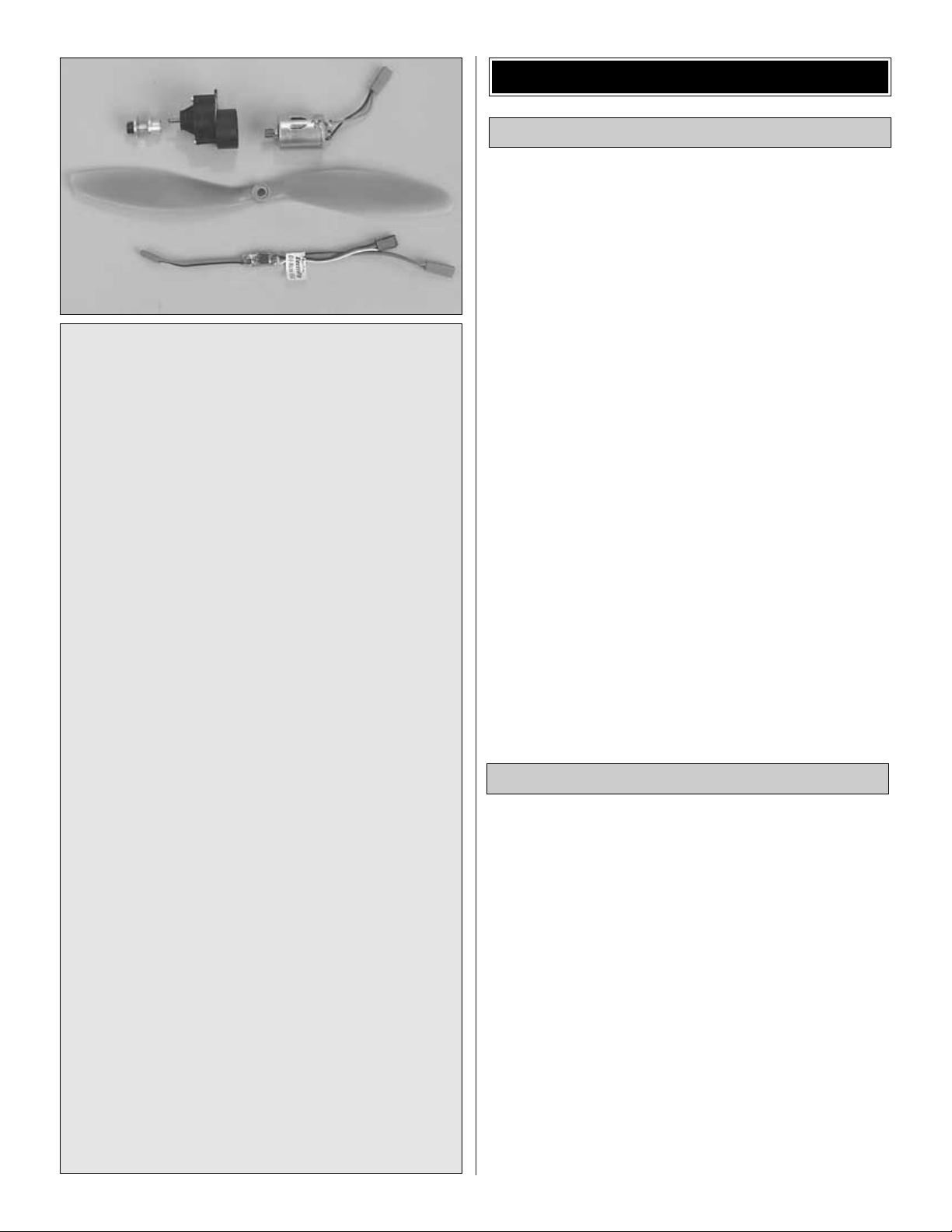
Motor System
The Li’l Poke is designed to use the Great Planes
ElectriFly T-280GD Motor System and gear drive for
electric flight (GPMG0430). This system includes a T-280
Ferrite Motor, S-280 4.1:1 ratio gearbox, 3mm prop
adapter, APC 10 x 4.7 propeller and the ElectriFly C-10
Nano
High Frequency Electronic Speed Control w/BEC.
The same components are also available without the
speed control by ordering number GPMG0445.
Note: Though the C-5 speed control is recommended,
the C-10 speed control included with the complete
system is suitable.
Battery and Charger
The ElectriFly 9.6V 350mAh NiCd pack (GPMP0070) is
recommended for the Li’l Poke.
The Great Planes ElectriFly Peak Charger (GPMM3000)
is recommended for charging this battery. It is a
peak
charger and charges the batteries until they are fully
charged, then automatically switches to trickle charge.
This charger is also suitable for nickel-metal hydride
batteries and transmitter battery packs.
Covering
There are several types of covering that may be used on the
Li’l Poke. Select a covering recommended specifically for
lightweight models. Coverite™CoverLite,™Coverite Micafilm
and Top Flite®EconoKote®are suitable. CoverLite is highly
recommended due to its light weight, with Micafilm being a
good second choice. Both materials require the application
of an adhesive such as Balsarite™(COVR2500) to the
structure. Top Flite EconoKote already has an adhesive on
the back so it is easier to apply, but it is also slightly heavier.
If using Coverlite, two 36" x 19.5" [915 x 495mm] packages
will be required.
Building Board
A flat building board that you can stick pins into is
required. A 12" x 24" [300 x 600mm] Great Planes Pro
™
Building Board (GPMR6946) is recommended. The back
of a 2' x 4' ceiling tile or a section cut from a sheet of
Celotex insulation board is also suitable.
Page 5
For the best performance, the Li’l Poke must be built light.
One of the best ways to insure light weight is to build neatly
and make good-fitting glue joints. Here are some tips to help
you build neatly and light.
1. An accurate, easy way to cut balsa sticks is with a singleedge razor blade. To do so, position the stick over the plan
or glue joint, then align the razor blade on the stick where it
is to be cut.
2. Press down lightly on the razor blade to make a mark.
Take the stick off the plan and cut it over a cutting mat or a
scrap piece of wood. (
With care, the stick could be cut on
the plan, but cutting through any protective covering on the
plan may cause the assembly to stick to the building board
).
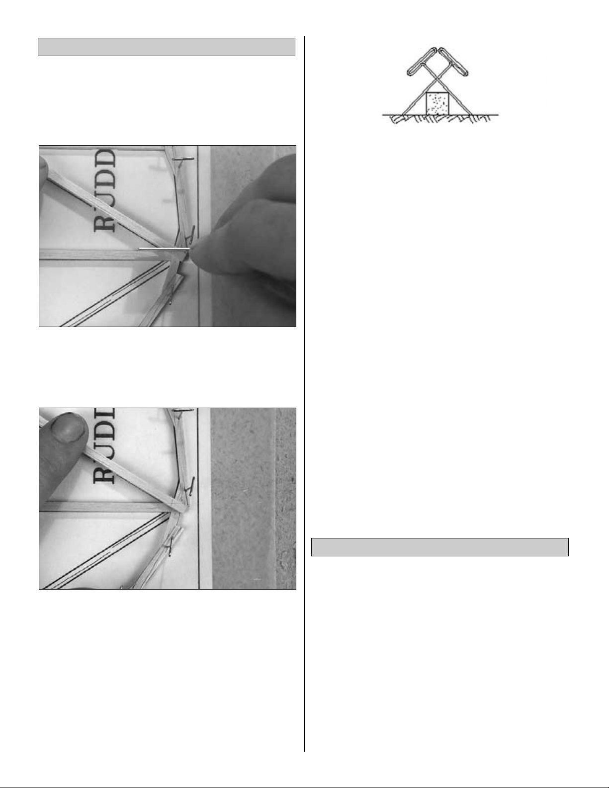
3. To avoid splitting the 1/8" x 1/8" [3.2 x 3.2mm] balsa
sticks used in the Li’l Poke, only small T-pins (HCAR5100)
or small pins found in craft stores should be used for
building this model. Do not stick pins into the sticks near the
ends, or the wood may split.
4. An alternate method to sticking pins directly through
balsa sticks is to use the “crossed-pin” technique by
inserting pins into the building board over the sticks in a
criss-cross fashion.
5. Only a small amount of CA should be used to glue the
parts together. In addition to unnecessary weight, excess
hardened CA is difficult to sand. Use the included CA
applicator tips to control and pinpoint the amount of CA that
comes from the bottle. When the tip becomes clogged, cut
the tip off and continue. If additional CA tips are required,
order number GPMR6033 (5).
6. When applying CA, be careful to not glue your fingers to the
structure. In the process of
unsticking
fingers you can
inadvertently damage the structure, thus requiring repairs and
adding additional weight
(not to mention the aggravation!)
.
7. Sanding requires a light touch to avoid damage.The best
method for sanding is to use light strokes in the direction of
the longest sticks. Be certain the sandpaper is thoroughly
bonded to the bar sander. Lifted edges may catch the
structure. Use medium-grit sandpaper such as 120 or 150.
8. One of the best ways to insure a lightweight model is to
proceed slowly and build neatly. Good glue joints are
stronger, lighter and have a better appearance than poorfitting joints with too much CA. Of course, this approach
should be taken with all of your projects!
9. Work over a flat surface. Cover the plans with Great
Planes Plan Protector (GPMR6167) or wax paper so the
parts will not adhere to the plan.
1/64" = .4mm
1/32" = .8mm
1/16" = 1.6mm
3/32" = 2.4mm
1/8" = 3.2mm
5/32" = 4mm
3/16" = 4.8mm
1/4" = 6.4mm
3/8" = 9.5mm
1/2" = 12.7mm
5/8" = 15.9mm
3/4" = 19mm
1" = 25.4mm
2" = 50.8mm
3" = 76.2mm
6" = 152.4mm
12" = 304.8mm
15" = 381mm
18" = 457.2mm
21" = 533.4mm
24" = 609.6mm
30" = 762mm
36" = 914.4mm
1" = 25.4mm (conversion factor)
Metric Conversions
IMPORTANT BUILDING NOTES
5
Page 6
6
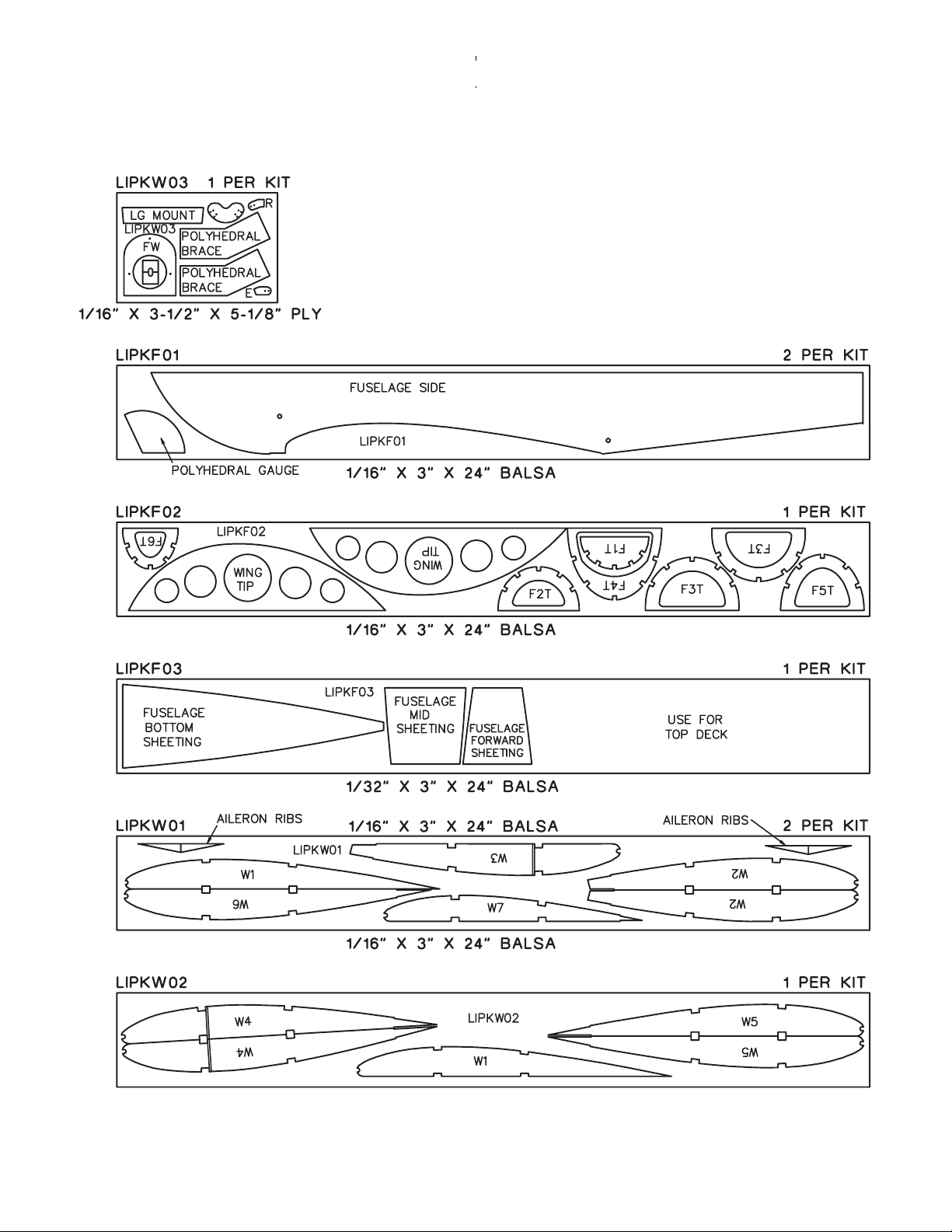
LASER-CUT PATTERNS
Page 7
❏ 1. Unroll the plan sheets and re-roll them inside-out so
they will lie flat. Position the fuse plan so the fin and rudder
are over your flat building board (or cut the fin and rudder
from the plan and place it over the building board).Cover the
plan with Great Planes Plan Protector or waxed paper so
glue will not adhere to it.
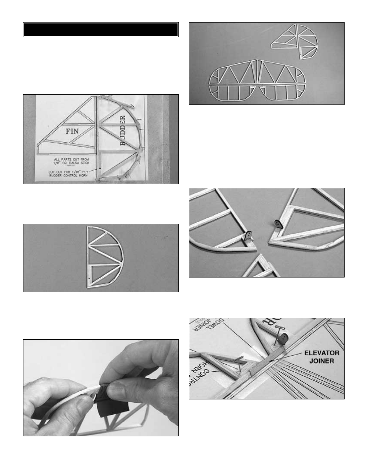
❏ 2. Build the rudder using two 1/8" x 1/8" x 24" [3.2 x 3.2
x 610mm] balsa sticks. As shown in the photo, most of the
sticks don’t have to be cut to exact length until after the
rudder is removed from the building board.
❏ 3. Remove the rudder from the building board. Cut and sand
the balsa sticks on the trailing edge to form a curved contour.
Use a bar sander with 150-grit sandpaper to bevel the leading
edge as shown in the cross section on the plan. Carefully sand
both sides of the rudder flat, even and smooth.
❏ 4. Holding a small sheet of 320-grit sandpaper by hand,
carefully round the trailing edge.
❏ 5. Build the fin, stab and elevators the same as the
rudder.When building the elevators, bevel the leading edges
and round the trailing edges, but do not permanently join
them to each other with the joiner until instructed to do so.
❏ 6. Test fit a .030" [.76mm] pushrod wire in the holes of the
laser-cut 1/16" [1.6mm] plywood elevator and rudder
control horns (marked “E” and “R”). If necessary, carefully
enlarge the holes with a #68 (or 1/32" [.8mm]) drill or a
hobby knife.
❏ 7. Cut the slots in the elevator and rudder to accommodate
the control horns, then glue the horns into position. Be certain
the elevator horn is in the bottom of the right elevator and that
the rudder horn is on the left side of the rudder.
❏ 8. Pin both elevators, upside-down, over their location on
the plan. Sand a bevel to one edge of the 1/8" x 1/8" x 1-1/2"
[3.2 x 3.2 x 38mm] basswood elevator joiner to match the
bevel on the leading edge of the elevators. Securely glue the
elevator joiner to both elevators.
Now it’s time to build the wing.
BUILD THE TAIL SURFACES
7
Page 8
Refer to this photo for the following four steps.
❏ 1. Position the wing plan so the center section is over
your flat building board (or cut the center section from the
wing plan). Cover the plan with Plan Protector.
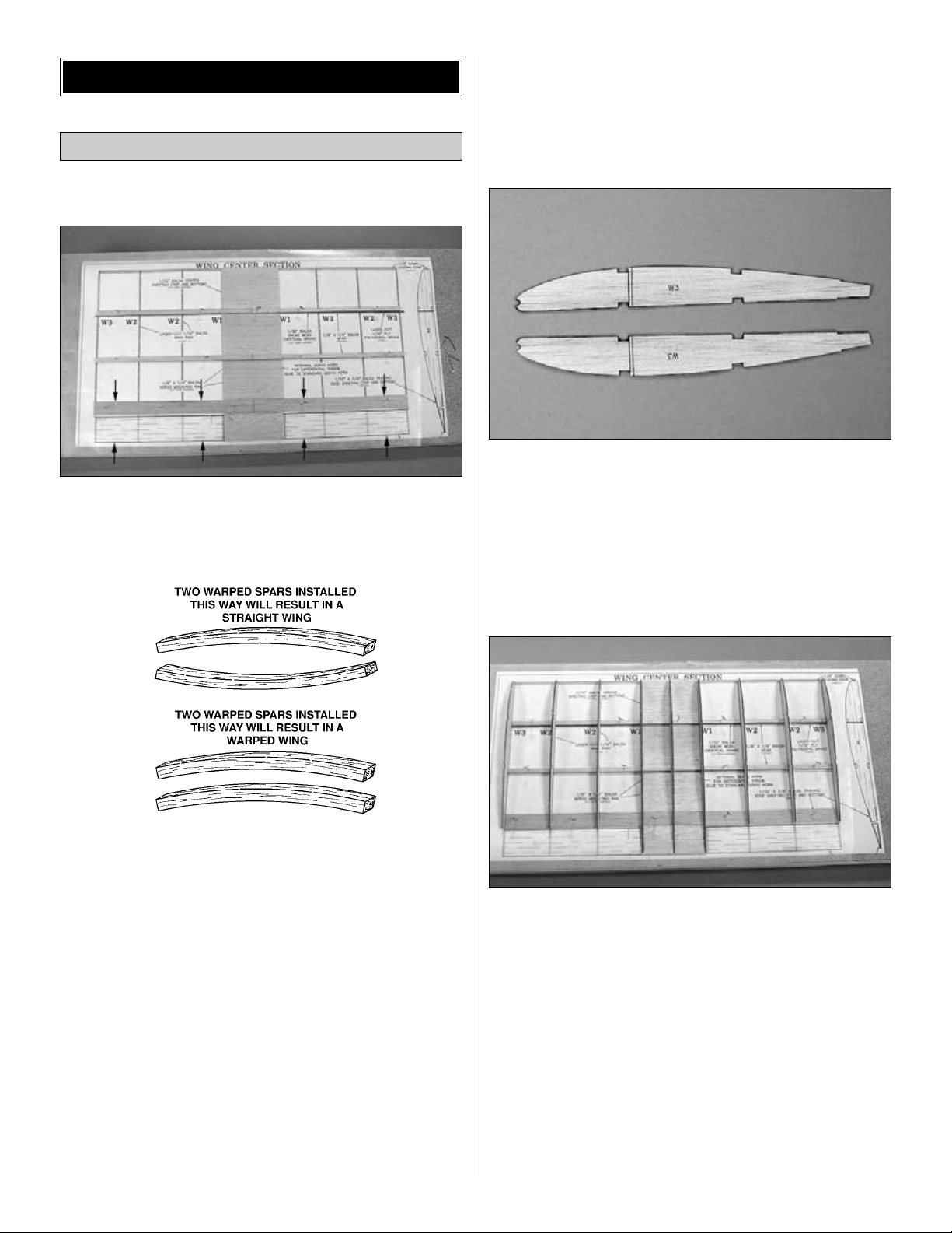
❏ 2. Examine the 1/8" x 1/4" x 24" [3.2 x 6.4 x 610mm]
balsa sticks included in this kit (which will be used for the
spars). If any of the spars are bowed, pair them together and
install them in the wing so any bows present will cancel-out.
❏ 3. Cut both bottom spars to the length shown on the
plan from two 1/8" x 1/4" x 24" [3.2 x 6.4 x 610mm] balsa
sticks. Pin the spars into position over the plan.
❏ 4. If building the wing with ailerons, cut a 3/4" [19.1mm]
wide bottom trailing edge sheet from a 1/32" x 3" x 24" [.8
x 76 x 610mm] balsa sheet and pin it into position over the
plan. If not building the wing with ailerons, cut the bottom
trailing edge sheet to extend all the way to the trailing edge
of the wing (as indicated by the arrows in the photo).
❏ 5. Mark the location of the center rib W1 on the spars and
trailing edge sheet.
❏ 6. Cut the four pieces of the bottom center section sheeting
from a 1/32" x 3" x 15" [.8 x 76 x 380mm] balsa sheet. The
forward sheet should be cut approximately 1/8" [3.2mm]
oversize, so it can extend to the leading edge dowel. Glue the
sheeting to the spars and trailing edge sheet as shown.
❏ 7. Note the vertical lines aft of the spar notches on both
laser-cut 1/16" [1.6mm] balsa ribs W3. These lines indicate
where a section of balsa is to be removed to accommodate
the 1/16" [1.6mm] polyhedral braces when it’s time to join
the wing panels. Use a straightedge and a ballpoint pen to
mark the same lines on the other side of one of the W3’s, so
the lines will be on the outside of both ribs when positioned
on the outer panels.
❏ 8. Glue the laser cut ribs W1 through W3 to the spars and
bottom center sheeting using a small builder’s square to be
certain they are vertical. Be certain the W3’s are positioned
so the lines are on the outside.
❏ 9. Cut the leading edge from the 1/8" x 24" [3.2 x
610mm] dowel, then glue it into position.
❏ 10. If building the wing without ailerons, glue the laser-
cut 1/16" [1.6mm] balsa aileron ribs to the bottom trailing
edge sheeting in alignment with the wing ribs.
Note: The aileron ribs can be seen in step 2 on page 11
where they are being glued to the bottom aileron sheeting.
Build the Center Section
BUILD THE WING
8
Page 9

Refer to this photo for the following four steps.
❏ 11. Cut the top spars from two more 1/8" x 1/4" x 24" [3.2
x 6.4 x 610mm] balsa sticks and glue them into the notches
in the top of the ribs.
❏ 12. If building the wing with ailerons, cut a 3/4" [19.1mm]
wide top trailing edge sheet from a 1/32" x 3" x 24" [.8 x 76 x
610mm] balsa sheet and glue it into position as shown in the
photo. If not building the wing with ailerons, cut the top trailing
edge sheet to extend all the way to the trailing edge of the wing,
then glue it into position over the aileron ribs.
❏ 13. Use a 1/32" x 3" x 15" [.8 x 76 x 380mm] balsa sheet
to sheet the top of the center section between the leading
edge dowel and the forward spar and between the aft spar
and the trailing edge sheet.
❏ 14. Cut the shear webs that go between the ribs on the
back of the top and bottom main spars from a 1/32" x 3" x
15" [.8 x 76 x 380mm] balsa sheet (if building ailerons, save
the remainder of this sheet for making the bottom aileron
sheeting). Note that the grain of the shear webs is vertical.
Glue the shear webs into position. Do not glue the section
of webbing that goes between the polyhedral joiner and rib
W2 until after the outer panels are joined to the inner
panels. Also be certain the shear webbing between the W1
ribs extends to 1/32" [.8mm] below the top surface of the top
spar to accommodate the top sheeting.
❏ 15. Sheet the top of the center section between the two
spars.
❏ 16. Remove the center section from the building board.
Trim the forward bottom center section sheeting to fit the
leading edge dowel. Lightly wet the front of the sheet to
bend it up, then glue it to the dowel.
❏ 17. Lightly and carefully sand the sheeting on the top and
bottom of the center section smooth and even with the
spars. Lightly sand the tops and bottoms of the ribs just
enough to remove any irregularities or rough edges. Use an
11" [280mm] bar sander with 150-grit sandpaper to sand
any protruding spars or sheeting even with the W3 ribs on
both ends of the center section.
Build the left panel first so yours will look like the photos the
first time through.
❏ 1. Position the outer panel plans over your flat building
board and cover them with Plan Protector.
Refer to this photo for the following three steps.
❏❏2. Pin one of the laser-cut 1/16" [1.6mm] balsa wing
tips over its location on the plan.
❏❏3. Use the pattern on the wing plan to make the top and
bottom outer trailing edge sheeting from a 1/32" x 3" x 15"
[.8 x 76 x 380mm] balsa sheet. Pin one of the sheets over its
location on the plan, but do not glue it to the wing tip yet.
❏❏4. Cut the bottom spars from a 1/8" x 1/4" x 24" [3.2 x
6.4 x 610mm] balsa stick and pin them to the plan.
Build the Outer Panels
9
Page 10

Refer to this photo for the following four steps.
❏❏5. Glue the laser-cut 1/16" [1.6mm] balsa ribs W5
through W7 to the bottom spars and trailing edge sheeting.
Also glue rib W7 and the trailing edge sheeting to the tip.
❏❏6. Cut one of the top spars from the remainder of the
1/8" x 1/4" [3.2 x 6.4mm] balsa sticks used for the bottom
spars. Cut the other top spar from another 1/8" x 1/4" x 24"
[3.2 x 6.4 x 610mm] balsa stick. Use a small razor saw or a
single-edge razor blade to cut partway through both top
spars at rib W6 so they can make the bend downward. Glue
the top spars to ribs W5 through W7.
Note: The spars extend to W4.
❏❏7. Position, but do not glue one of the laser-cut 1/16"
[1.6mm] balsa W4 ribs on the panel so the vertical cutlines
for the polyhedral braces are facing the outside (toward the
fuse). Using the laser-cut 1/16" balsa polyhedral gauge,
set rib W4 at the correct angle and glue it into position.
❏❏8. Glue the top trailing edge sheet into position. Cut the
leading edge dowel to the correct length from the 1/8" x 24"
[3.2 x 610mm] hardwood dowel (after building the second
outer panel, save the remainder of the dowel for the wing
and landing gear dowels on the fuse). Cut partway through
the dowel at rib W6 allowing it to bend toward rib W7, then
glue the dowel into position.
❏❏9. Make the wing tip supports from leftover 1/8" x 1/4"
[3.2 x 6.4mm] balsa and glue them into position.
❏❏10. Remove the left wing panel from the plan. Sand the
leading edge dowel, spars and trailing edge sheeting flat
and even with rib W4. Sand the spars even with the tops and
bottoms of the ribs.
❏ 11. Return to step 2 and build the right wing panel the
same way.
❏ 1. Cut through the lines on ribs W3 and W4 on both ends
of the center section and on the ends of both outer panels.
Remove the section of balsa to accommodate the laser-cut
1/16" [1.6mm] plywood polyhedral braces.
Join the Outer Panels
to the Center Section
10
Page 11

❏ 2. Test join both outer panels to the center section with
the polyhedral braces. Use small clamps to temporarily hold
everything together. Both wing tips under rib W7 should be
3" [76mm] above the workbench. If the distance is not
exactly 3" [76mm] it’s okay, as long as it’s close and both tips
are the same. Hint: Cut a leftover balsa stick to the correct
length and use it as a gauge for both wing tips.
❏ 3. Once satisfied with the fit, separate the panels. Cover
your workbench with a sheet of Plan Protector. Mix up a
batch of 30-minute epoxy, then coat all joining surfaces.
Rejoin the panels with the polyhedral braces and place the
wing on your protected workbench. Position the clamps and
wipe away excess epoxy before it hardens. Do not disturb
the wing until after the epoxy hardens. Hint: If more working
time is required, join one wing panel at a time with separate
batches of epoxy.
❏ 4. Glue in the rest of the 1/32" [.8mm] shear webbing
between the ends of the polyhedral braces and ribs W2.
Skip this section if not building ailerons.
Only the left aileron is shown in the photos, but both ailerons
are built at the same time.
❏ 1. Cut two bottom aileron sheets to the size shown on
the plan from the 1/32" x 3" [.8 x 76mm] balsa sheets
leftover from making the shear webs. Pin the sheets over
their location on the plan.
❏ 2. Glue the laser-cut 1/16" [1.6mm] balsa aileron ribs to the
sheet where indicated on the plan.
❏ 3. Cut the top aileron sheets from a 1/32" x 3" x 15" [.8
x 76 x 380mm] balsa sheet. Note that the top sheets should
be 1/16" [1.6mm] wider than the bottom sheets. Glue the top
aileron sheets to the bottom aileron sheets and the ribs.
❏ 4. Remove the ailerons from the plan. True all edges with
a bar sander and 150-grit sandpaper.
❏ 5. Cut a 1-1/8" [29mm] torque rod tube from both 1/16"
x 12" [1.6 x 305mm] aluminum tubes. This is best done by
rolling the tubing under a #11 blade on the workbench to cut
the tubing without burring the end.
Build the Ailerons
11
Page 12

Refer to this photo to make the aileron torque rods.
Make the left one first.
❏ 6. Cut 1" [25mm] from one end of the .030" x 20-1/2" [.76
x 520mm] wire and clamp it in a vice. Cut another 5"
[130mm] from the wire and make a loop near one end by
pulling it around the wire clamped in the vice.
❏ 7. Cut the excess wire from the loop. Make the first 90degree outward bend 1/2" [13mm] below the loop. Slide the
1-1/8" [29mm] aluminum torque rod tube onto the wire.
❏ 8. Make the final bend in the wire, then cut the wire to
length shown on the plan.
❏ 9. Cut another 5" [130mm] from the wire and make the
right aileron torque rod the same way. Note that the right
torque rod is a little longer than the left.
❏ 10. Make two torque rod supports from leftover 1/16"
[1.6mm] balsa. When resting on the supports, the torque
rods should align with the bottom surface of the trailing edge
sheeting. Glue the supports into position, then glue the
torque rod bearing tubes to the supports.
❏ 11. Sheet the remainder of the top of the center section.
Fill any gaps with balsa filler and sand when dry.
Refer to this photo for the following three steps.
❏ 12. Cut holes in the top sheeting for the aileron servo and
the servo wire. Glue pieces of leftover 1/8" x 1/4" [3.2 x
6.4mm] balsa to the inside of the top sheeting for the aileron
servo mounting screws. Drill 1/16" [1.6mm] holes for the
screws and add a few drops of thin CA to the holes. Allow
the CA to fully dry, then mount the servo in the wing.
12
Page 13

❏ 13. Drill #68 (or 1/32" [.8mm]) holes through the marks in
the laser-cut 1/16" [1.6mm] plywood servo wheel. Roughen
the top of the plastic servo arm that came with the servo so
glue will adhere. Glue the plywood servo wheel to the top of
the servo arm.
❏ 14. Make the aileron pushrods from the remaining piece
of .030" [.76mm] wire you used to make the torque rods.
Use needle-nose pliers to make Z-bends on the ends of the
pushrods and connect them to the servo wheel and the
torque rods.
Set the wing aside and get started on the fuse.
❏ 1. Cover the front view of the fuselage formers on the
plan with Great Planes Plan Protector.
❏ 2. Just the same as the tail surfaces were built, build
formers F1 through F6 over the plan using three 1/8" x 1/8"
x 24" [3.2 x 3.2 x 610mm] balsa sticks. After the glue
hardens remove the formers from the plan and lightly sand
them flat and even. Note: Most of the formers are different
enough to easily identify, except for formers F2 and F5, so
label both formers so they don’t get switched later.
❏ 3. Pin both laser-cut 1/16" [1.6mm] balsa fuselage sides
to the side-view of the plan making certain they are
accurately aligned with each other and the plan. Align a
small straightedge with the front of former F1 where
indicated by the tick-marks on the plan. Stick a T-pin through
both fuse sides near the top and bottom along the
straightedge.
❏ 4. Mark the location of the rest of the formers the same
way. When the fuse sides are separated, the pinholes will
mark the location of the formers.
❏ 5. Remove the fuse sides from the plan. Place them together
on your workbench so the top edges are contacting each other.
Label the bottom side as “R” and the other as “L”. Mark the
locations of the front edge of the formers by drawing a line
across the pinholes with a straightedge and a ballpoint pen.
❏ 6. Cut the firewall alignment template from the plan.
Align the aft edge of the template with the line noting former
F1. Use a ballpoint pen to mark the front edge of the firewall
using the template as a guide.
❏ 7. Accurately cut the top deck template from the plan.
Use the template to make the top deck from the excess
1/32" [.8mm] sheeting on the end of the die sheet that the
forward and aft fuse bottom come from.
Frame the Sides
BUILD THE FUSELAGE
13
Page 14

❏ 8. Cover the top view of the fuse plan with Great Planes
Plan Protector. Pin the top deck to the building board over
its location on the plan. Pin formers F1 through F6 to the
building board and the top deck, accurately aligned over
their locations on the plan.
❏ 9. Cut the pushrod exit template from inside the top
deck template. Use the pushrod exit template as a guide to
cut the rudder pushrod exit slot in the right fuselage side
and the elevator pushrod exit slot in the left fuselage side.
❏ 10. Test fit the fuse sides to the formers and the top deck
on the plan. Use T-pins to hold the fuse sides in position.
Make certain the lines you drew on the inside of the fuse
sides align with the formers and make certain the top edges
of the fuse sides are fully contacting the plan.
Hint: Use blocks cut from a 1/4" x 1/2" [6 x 13mm] (or similar
size, not included) balsa stick, held to the plan with T-pins, to
tightly hold the fuse sides to the formers and top deck.
❏ 11. Cut the forward wing/landing gear dowel and the
aft wing dowel to a length of 3-1/2" [90mm] from the
remainder of the 1/8" dowel used for the leading edge of the
outer panels.
❏ 12. Round both ends of the dowels and fit them into the
holes in the fuselage. Do not glue the dowels into position
until after the model has been covered.
❏ 13. Cut 2-1/2" from the 1/8" x 1/8" x 24" [3.2 x 3.2mm]
balsa stick leftover from building the formers. Place the stick
between the aft edge of the fuse sides and hold it in position
with a small clamp or masking tape. Be certain the aft end
of the fuse is centered over the plan. Use a small builder’s
square to make certain the fuse sides are perpendicular to
the building board. Once alignment has been confirmed,
glue the stick into position.
❏ 14. Trim the 1/8" x 1/8" x 24" [3.2 x 3.2mm] balsa stick
glued between the aft fuse sides even with the bottom of the
fuse. Sand the bottoms of any protruding formers even with
the bottom edges of the fuse sides to accommodate the
bottom sheeting.
❏ 15. Glue the laser-cut 1/32" [.8mm] balsa aft fuse
bottom to the fuse sides and formers.
14
Page 15

❏ 16. Glue the laser-cut 1/16" [1.6mm] plywood landing
gear mount into position, followed by the laser-cut 1/32"
[.8mm] balsa mid fuse bottom.
❏ 17. Remove the fuse from the plan. Sand the bottom
sheeting even with the fuse sides.
❏ 18. Glue strips of leftover 1/16" [1.6mm] balsa to one side
of the laser-cut 1/16" [1.6mm] plywood firewall across the
holes for the motor mount screws. Drill 1/16" [1.6mm] holes
through the laser-cut marks in the firewall for the gearbox
mounting screws.
❏ 19. Glue the firewall between the fuse sides using the
lines marked earlier as a guide. Glue the laser-cut 1/32"
[.8mm] balsa forward fuse bottom into position.
Note: The forward fuse bottom is supplied oversize. Trim it
so that it butts against the rear of the firewall as shown on
the plan.
❏ 20. Glue the laser-cut 1/16" [1.6mm] balsa former tops
F1T through F6T to the top of the fuselage where shown on
the plan.
❏ 1. If you’ve built the wing with ailerons, remove the
bottom horizontal brace from former F4 to accommodate
the aileron servo.
❏ 2. Lay the wing on your workbench or a sturdy platform
and place the fuselage on the wing. Place a weight on top
of the fuse to hold it down and keep it from moving. Position
the stab on the fuse and place a small weight on top of it to
hold it down. Stand a few feet behind the model and view the
horizontal alignment of the stab and wing. If the stab and
wing are parallel, proceed to the next step. If the stab and
wing are not parallel, carefully sand the high fuse side to
bring the stab into alignment with the wing.
❏ 3. Take the fuse off the wing and place it on the plan,
accurately aligning it over the top view. Place a straightedge
on the plan, accurately aligning it with the dashed line
Mount the Stabilizer and Fin
15
Page 16

indicating the trailing edge of the stab. Mark the center of
the trailing edge of the stab. Using the mark as a reference,
center the stab laterally on the fuse. View the model from
above. Align the trailing edge of the stab so it is parallel with
the straightedge on the plan. Now you know how to center
the stab.
❏ 4. Glue the stab to the fuse with 30-minute epoxy. Be certain
the trailing edge of the stab is 1/8" [3.2mm] ahead of the aft end
of the fuse to accommodate the elevator joiner. Be certain the
fuse and the straightedge remain aligned on the plan. Align the
trailing edge of the stab with the straightedge. Wipe away
excess epoxy, then recheck alignment.
Note: CA could be used to glue the stab to the fuse, but
epoxy is recommended to provide working time for
accurate alignment.
❏ 5. Temporarily place a 1/8" x 1/8" x 24" [3.2 x 3.2mm] stringer
in the top, middle notch of the formers. Position the fin on the
stab and fuse. Align the trailing edge of the fin with the aft end
of the fuselage. Center the leading edge of the fin on the stringer
in the top of the formers. Holding the fin in position, use a small
builder’s square to make certain it is perpendicular to the stab.
When the fin is in alignment, glue it into position with CA.
❏ 1. Cut the stringers that extend from F4T to the leading
and trailing edges of the fin from 1/8" x 1/8" x 24" [3.2 x 3.2
x 610mm] balsa sticks. Cut an angle at the aft end of the
stringers where they contact the trailing edge of the fin. Glue
the stringers into position.
❏ 2. Cut the 1/8" x 1/8" stringers used for bonding the covering
(indicated by the arrows in the photo) to both sides of the fin
and the top of the stab. Glue the stringers into position.
❏ 3. Glue both laser-cut 1/16" [1.6mm] plywood dowel
doublers to the inside of the fuse sides around the forward
dowel. This can be most accurately done with the dowels in
position, but do not inadvertently glue the dowels in.
❏ 4. Glue a strip of leftover 1/16" [1.6mm] plywood to the
back of the firewall centered over the top mark for the motor
mount screw. Drill a 1/16" [1.6mm] hole through the firewall
and the piece of plywood at the mark.
❏ 5. Use the remaining 1/8" x 1/8" x 24" [3.2 x 3.2 x 610mm]
balsa sticks to make the stringers for the top of the fuse that
Finish the Fuse
16
Page 17

extend from former F4T to the firewall. Note that the top,
middle stringer extends to 7/8" [22mm] aft of the forward
former F3T. Note that the stringers butt-glue to the back of
the firewall.
❏ 6. Use the cockpit sheeting pattern on the plan to make
the cockpit sheets from leftover 1/32" [.8mm] balsa. Glue the
sheets into position.
❏ 7. Glue 1/8" x 2-1/4" [3.2 x 57mm] strips of leftover 1/32"
[.8mm] balsa to the top of the stringers in front of the cockpit
sheeting. Sand the front of the strips until they feather
smoothly to the stringers, thus blending the cockpit sheeting
to the stringers.
❏ 8. Temporarily mount the gearbox to the firewall with
three #2 x 3/8" [9.5mm] screws.
❏ 9. Cut and test fit a piece of 1/32" [.8mm] balsa nose
sheeting to fit over the gearbox. Trim the sheet as
necessary for a good fit. Be certain the sheeting is
positioned so you will be able to access the top gearbox
mounting screw with your screwdriver. Glue the nose
sheeting into position. The same as the cockpit sheeting,
feather the nose sheeting to the stringers with strips of 1/32"
x 1/8" [.8 x 3.2mm] balsa.
❏ 10. Glue two strips of leftover 1/8" x 1/8" x 24" [3.2 x
3.2mm] balsa across the bottom of the landing gear mount
as shown on the plan. Temporarily mount the landing gear
using the small rubber bands included with this kit. Mount
the wheels to the gear by press-fitting the nylon retainers
onto the ends of the wire.
❏ 11. Apply a light coat of epoxy to the inside of both
fuselage sides in the area where the elevator and rudder
servos are to be mounted. Lightly sand the area smooth
after the epoxy hardens. This will provide a solid surface for
mounting the servos with double-sided foam mounting tape.
❏ 12. Use a thin razor saw to cut a slot in the aft end of the
fuse bottom to accommodate the small hinge that will be
used to join the bottom of the rudder to the fuse as shown
on the plan. Cut a matching slot in the middle of the bottom
of the rudder.
17
Page 18

❏ 1. If you haven’t done so already, sand all parts of the
model smooth with 320, then 400-grit sandpaper.
❏ 2. Handling the model with care, use compressed air, a dust
brush or a tack cloth to remove balsa dust from the model.
❏ 3. If using a covering that requires adhesive, apply the
adhesive according to the instructions that came with it.
❏ 4. Follow the suggested sequence to cover the model.
Important: When covering the wing and tail surfaces, do
not tighten the covering until both sides of each part are
covered. This will reduce the tendency for the surfaces to
twist. If the surfaces do twist, they can be straightened by
re-tightening the covering while twisting the structure in the
opposite direction.
Tail surfaces:
1. The bottom, then the top of the stabilizer
2. Fin
3. Bottom, then top of elevators
4. Rudder
Fuselage:
1. The bottom of the fuse
2. Sides
3. Top
Wing:
1. The bottom of the center panel
2. The bottom of both outer panels and bottom of
wing tips
3. Top of the center panel
4. Top of wing tips
5. Top of outer panels
6. Ailerons
❏ 1. Before proceeding, charge the motor battery (and your
transmitter if needed). When it’s time to set up the radio,
there will be no waiting for the batteries to charge.
❏ 2. Install and permanently glue in the aft wing dowel and
the forward landing gear dowel.
❏ 3. Make the tail skid as shown on the plan from leftover
1/8" x 1/4" [3.2 x 6.4mm] balsa. Remove the covering from
the bottom of the fuse where the tail skid is to be glued into
position. Glue the tail skid to the bottom of the fuse with CA.
❏ 4. Hold the elevator to the stab and move it up and down
to make sure there is no interference with the fuse. If
necessary, trim the bottom of the fin trailing edge or the top
of the aft end of the fuse to allow the elevator to move up
and down.
❏ 5. Cut the covering from the elevator and rudder pushrod
exit slots near the aft end of the fuse.
Note: Refer to elevator and rudder pushrods on the fuse
plan. Note that the pushrods are made from aluminum tubes
connected to wire rods at both ends. The following steps
describe how to make the pushrods.
❏ 6. Cut the two 1/16" [1.6mm] aluminum pushrod tubes
to the length shown on the plan for the elevator and
rudder pushrods.
❏ 7. Thoroughly clean the remaining .030" x 20-1/2" [.76 x
520mm] wire with alcohol or other solvent, then scuff with
320-grit sandpaper so glue will adhere.
❏ 8. Make all four pushrod ends as shown on the plan
from the wire. The ends should be cut to a length so that
they can be inserted 1-1/4" [32mm] into the aluminum
pushrod tubes.
Hook Up the Controls
FINAL ASSEMBLY
Suggested Covering Sequence
Final Preparations
COVER THE MODEL
18
Page 19

❏ 9. Make a slight bend about 1/2" [13mm] from the end of
the wires, then assemble the pushrods by inserting the
wires into the aluminum tubes. For now, the bends in the
wires should have a tight friction fit, but the wires will be
permanently glued into the tubes after the pushrods are
connected and the controls are centered.
❏ 10. Connect the elevator pushrod to the outer hole on the
elevator control arm. Insert the pushrod into the fuse
through the slot in the fuse side.
❏ 11. Hinge the top of both elevators to the stab with a few
strips of cellophane tape where shown on the plan.
❏ 12. Connect the other end of the pushrod to the servo
arm on the servo you will be using for the elevator. Using
double-sided foam mounting tape (GPMQ4440, not
included), mount the elevator servo to the fuse side where
shown on the plan. Be certain to position the servo so the
elevator will be neutral when the servo arm is centered.
❏ 13. Connect the rudder pushrod, hinge the rudder and
mount the rudder servo the same way.
❏ 14. Insert the small CA hinge into the slots cut earlier in
the bottom of the fuse and rudder. Add a few drops of thin
CA to both sides of the hinge and allow to soak in and dry.
❏ 15. Hinge the ailerons to the wing with strips of
cellophane tape while simultaneously using epoxy to glue
the aileron torque rods inside the top surface of the ailerons.
Flip the wing upside-down while the epoxy is hardening.
❏ 16. Assemble the gearbox and motor according to the
instructions that came with it. Mount the gearbox and motor
to the firewall. Mount the propeller adapter and propeller to
the gearbox.
❏ 17. Mount the landing gear to the fuse with two #14
rubber bands on each side.
❏ 18. Connect the servos and receiver to the speed control
following the instructions that came with the speed control.
Temporarily position the receiver inside the fuse and lay the
antenna along the outside of the fuse over the stab.
❏ 1. Use the windscreen template on the plan to cut out the
windscreen from the supplied 2" x 4" [50 x 100mm] clear
plastic sheet.
❏ 2. Test fit the windscreen to the fuse making small slits in
the balsa with a hobby knife for the tabs. Use CA or canopy
glue to glue the windscreen into position.
❏ 3. Install a molded plastic pilot of choice, or cut out one
of the paper templates provided and glue it to a sheet of 1/8"
[3.2mm] balsa. Cut out the balsa sheeting to the outline of
the pilot, then cut out and glue the other side of the template
to the balsa sheet. Use felt-tip markers to color the pilot,
then glue him into position inside the cockpit.
Finish the Cockpit
19
Page 20

Note: This section is VERY important and must NOT be
omitted! A model that is not properly balanced will be
unstable and possibly unflyable.
❏ 1. If using a Great Planes C.G. Machine to balance the Li’l
Poke, adjust the rulers to balance the model 2-5/8" [67mm]
back from the leading edge of the wing. If not using a C.G.
Machine, mark the balance point on the top of the wing on
both sides of the fuselage with 1/8" [3mm] wide striping tape
as shown in the photo. This is the balance point at which the
model should balance for the first flights. After initial trim
flights and when you become more acquainted with the Li’l
Poke, you may experiment by shifting the balance up to 1/4"
[6mm] forward or backward to change its flying
characteristics. Moving the balance point forward may
improve the smoothness and stability, but the model may then
require more speed for takeoff and may become more difficult
to slow down for landing. Moving the balance aft makes the
model more agile with a lighter “feel”. In any case, start at the
recommended location. Do not at any time balance the model
outside the recommended range.
❏ 2. Hook two #32 rubber bands together to double the
length. Hook two more #32 rubber bands together the same
way. Mount the wing to the fuse with the rubber bands.
❏ 3. With the model ready to fly and all parts installed
except for the battery, place the model on a Great Planes
C.G. Machine or lift it at the balance point marked on top of
the wing. Place the battery on the bottom of the model
where required to get it to balance. This is where the battery
pack must be installed in the fuse.
❏ 4. Noting where the battery must be mounted inside the
fuselage to achieve the correct C.G., remove the wing and
decide how to mount the battery. If the battery pack crosses
the forward dowel, it should fit between the dowel and the
top deck with a little room to spare. Use your own mounting
method or make a 1-1/4" x 2-1/2" [30 x 65mm] battery
mount from leftover 1/16" [1.6mm] balsa to reinforce the top
deck. Glue the battery mount to the top deck. Apply Great
Planes Velcro (GPMQ4480, not included), to the battery and
the battery mount, then mount the battery. Keep in mind that
the battery should be readily removable and should also be
repositionable for C.G. adjustments. Note: Only a couple of
1/4" [6mm] wide strips of Velcro are required to secure the
battery—do not use a whole sheet. Otherwise, the battery
may be difficult to remove.
❏ 5. Mount the receiver and the speed control to one of the
fuse sides or the top deck with Velcro or double-sided foam
mounting tape.
❏ 6. Drill a 1/16" [1.6mm] hole through the bottom of the
fuselage and route the receiver antenna through it. Extend the
antenna and tape it to the bottom of the aft end of the fuse. Be
certain the antenna will not be able to come into contact with
the propeller! Never coil-up the antenna inside the fuselage,
nor cut it. The antenna is tuned to a certain length.
❏ 7. Recheck the C.G. to make certain the model balances.
Shift the battery as necessary to achieve the correct C.G.
Balance the Model
PREPARE THE MODEL FOR FLYING
20
Page 21

❏ 1. For safety, remove the propeller from the motor. Move
the throttle stick to the off position, or towards the bottom of
the transmitter.Turn on the transmitter. Connect the charged
battery to the speed control then, follow the instructions that
came with the speed control to turn on the receiver.
❏ 2. Center the trims on the transmitter. Operate the servos
by moving the control sticks. Check that the servos respond
in the correct direction as shown in the diagram. If
necessary, use the servo reversing function on your
transmitter to get the controls to respond correctly.
❏ 3. If necessary, remove the servo arms from the servos,
then remount them so they are centered.
❏ 4. Now that the servos and the servo arms are centered,
center the rudder and elevator by adjusting the position of
the wire pushrod ends in the pushrod tubes. Once the
controls are centered, permanently glue the pushrod ends
into the pushrod tubes with thin CA. If the ailerons require
adjustment, carefully bend the aileron torque rods or the
pushrods until both ailerons are centered.
❏ Operating the controls with the transmitter, use a ruler to
measure the throws at the widest part of the surface. If
necessary, reposition the pushrods on the servo arms
(farther out for more throw, closer in for less throw), or use
the ATV function on the transmitter to set the control throws
according to the chart that follows.
Follow the instructions that came with your radio to charge
the batteries the evening before you plan to fly. You should
always charge the transmitter batteries before flying and at
other times as recommended by the radio manufacturer.
Charge the Transmitter Batteries
PREFLIGHT
These are the recommended control throws:
Elevator: 5/8" [16mm] up 5/8" [16mm] down
Rudder: 1" [25mm] right 1" [25mm] left
Ailerons: 5/8" [16mm] up 1/8" [3mm] down
IMPORTANT: The Li’l Poke has been extensively tested.
These are the control throws at which it flies best. If, after
you become comfortable with the way the Li’l Poke flies, you
would like to adjust the throws to suit your taste, that is fine.
However, remember that too much throw can make the
plane more difficult to control and force it into a stall or a
snap roll, so remember, “more is not always better.”
Set the Control Throws
Warning: When not flying or working on the model, the
battery should be disconnected.
Set Up the Radio
21
4-CHANNEL
TRANSMITTER
4-CHANNEL
TRANSMITTER
4-CHANNEL
TRANSMITTER
4-CHANNEL
TRANSMITTER
Page 22

No matter if you fly at an AMA sanctioned R/C club site or if you
fly somewhere on your own, you should always have your
name, address, telephone number and AMA number on or
inside your model. It is required at all AMA R/C club flying sites
and AMA sanctioned flying events. Fill out the identification tag
on the back cover and place it on or inside your model.
Before flying you should perform one last overall inspection
to make sure the model is truly ready to fly and that you
haven’t overlooked anything. If you are not thoroughly
familiar with the operation of R/C models, ask an
experienced modeler to perform this inspection. Check to
see that the radio is installed correctly and that all the
controls are connected properly. The motor must also be
checked by confirming that the prop is rotating in the correct
direction and the motor sounds like it is reaching full power.
Make certain all control surfaces (elevators, rudder,
ailerons-if used) are secure, the pushrods are connected,
the controls respond in the correct direction, radio
components are securely mounted, and the C.G. is correct.
Ground check the operational range of the radio before the
first flight of the day. With the transmitter antenna collapsed
and the receiver and transmitter on, you should be able to
walk at least 100 feet away from the model and still have
control. Have an assistant stand by the model and while
you work the controls, tell you what the control surfaces are
doing. Repeat this test with the motor running at various
speeds. If the control surfaces do not respond correctly, do
not fly! Find and correct the problem first. Look for loose
servo connections or broken wires, corroded wires on old
servo connectors, poor solder joints in your battery pack or
a defective cell, or a damaged receiver crystal from a
previous crash.
For the longest flight duration, and to get the most from a new
battery, the battery should be cycled. “Cycling” a battery means
to fully charge (“peak” charge) the battery, then to discharge it.
Many battery chargers have peak charging and automatic
discharging capabilities. If you do not have a charger that is
able to discharge batteries, you can discharge the battery
yourself by running the motor with the propeller attached until
the propeller barely continues to turn. Charge and discharge
the battery 3 or 4 more times on the ground before flying. Be
sure to remove the battery from the airplane between each
cycle and allow it to cool before recharging.
Use fine sandpaper to remove imperfections along the
edges of the propeller. For the best performance, use a Top
Flite Precision Magnetic Prop Balancer™ (TOPQ5700) to
balance the propellers (this is a necessity on glow-powered
engines, but is less critical on small electric models).
Make two more long rubber bands by connecting two sets
of two #32 rubber bands. Mount the wing with all four rubber
bands criss-crossing the last two.
1. Using multiple battery packs for successive flights may
cause the motor to become excessively hot, thus causing
damage. Allow the motor to cool for at least 10 minutes
between flights.
2. The ideal power source for the Li’l Poke system is a 7 or
8-cell (8.4 - 9.6volt) battery pack. The use of a higher voltage
battery may reduce motor life.
If taking off from the ground, the wheels must spin freely.
Put a drop of oil on each axle and check the wheels for
binding when moved from side to side.
Note: Failure to follow these safety precautions may result
in severe injury to yourself and others.
Get help from an experienced pilot when learning to operate
the motor.
Use safety glasses when running the motor.
Do not run the motor in an area of loose gravel or sand; the
propeller may throw such material in your face or eyes.
Keep your face and body as well as all spectators away from
the path of the propeller as you start and run the motor.
Keep items such as these away from the prop: loose
clothing, shirt sleeves, ties, scarfs, long hair or loose objects
(pencils, screw drivers) that may fall out of shirt or jacket
pockets into the prop.
MOTOR SAFETY PRECAUTIONS
Oil the Wheels
Motor Care
Mount the Wing
Examine the Propeller
Cycle the Batteries
PERFORMANCE TIPS
Range Check
Ground Inspection
Identify Your Model
22
Page 23

The electric motor and motor battery used in your Li’l Poke
are very powerful and the spinning propeller has a lot of
momentum; therefore, if you touch the propeller while it is
spinning it may inflict severe injury. Respect the motor and
propeller for the damage it is capable of and take whatever
precautions are necessary to avoid injury. Always
disconnect and remove the motor battery until you are
ready to fly again and always make sure the switches are
turned off before connecting the battery.
Read and abide by the following Academy of Model
Aeronautics Official Safety Code:
GENERAL
1. I will not fly my model aircraft in competition or in the
presence of spectators until it has been proven to be airworthy
by having been previously successfully flight tested.
2. I will not fly my model aircraft higher than approximately
400 feet within 3 miles of an airport without notifying the
airport operator. I will give right of way to and avoid flying in
the proximity of full scale aircraft. Where necessary an
observer shall be utilized to supervise flying to avoid having
models fly in the proximity of full scale aircraft.
3. Where established, I will abide by the safety rules for the
flying site I use and I will not willfully and deliberately fly my
models in a careless, reckless and/or dangerous manner.
7. I will not fly my model unless it is identified with my name
and address or AMA number, on or in the model.
RADIO CONTROL
1. I will have completed a successful radio equipment
ground check before the first flight of a new or repaired
model.
2. I will not fly my model aircraft in the presence of
spectators until I become a qualified flyer, unless assisted
by an experienced helper.
3. I will perform my initial turn after takeoff away from the pit,
spectator and parking areas and I will not thereafter perform
maneuvers, flights of any sort or landing approaches over a
pit, spectator or parking area.
4. I will operate my model using only radio control
frequencies currently allowed by the Federal
Communications Commission.
Though the Li’l Poke is a “Park Flyer” that may be flown in
small areas, the best place to fly any R/C model is at an
AMA chartered club field. Club fields are set up for R/C
flying making your outing safer and more enjoyable. We
recommend that you join the AMA and a local club so you
can have a safe place to fly and have insurance coverage in
case of a flying accident. The AMA address and telephone
number are in the front of this manual. Remember, if you
insist on flying on your own, do not fly the Li’l Poke
within five miles of any R/C club field, or interference
from your transmitter could cause a crash.
If there is no club or R/C flying field in your area, find a
suitable site that is clear of trees, telephone poles, buildings,
towers, busy streets and other obstacles. Since you are not
flying at a sanctioned AMA site, beware of others like
yourself who could be flying nearby on your frequency.
IMPORTANT: Although the Li’l Poke is a slow-flying model,
it does not have the self-righting characteristics of a primary
trainer. If you have not mastered basic flight with a trainer
model, we strongly urge you to seek the assistance of an
experienced R/C pilot to check the model for airworthiness
AND to teach you how to fly. Attempting to learn to fly on
your own is dangerous and may result in destruction of your
model or even injury to yourself and others. Therefore, find
an instructor and fly only under his or her guidance until you
have acquired the skills necessary for safe and fully
controlled operation.
We recommend flying the Li’l Poke when the wind is no
greater than five miles per hour. Less experienced flyers
should fly the Li’l Poke only in calm (less than one mile per
hour) conditions. Often, winds are calm in the early morning
and early evening. These are usually the most enjoyable
times to fly anyway!
Until you have the Li’l Poke properly trimmed for level flight,
we recommend having an assistant hand-launch the model
instead of taking off from the ground.
Turn on the transmitter and plug the battery into the speed
control.
IMPORTANT: Confirm that the transmitter operates the
controls by moving the sticks to turn on the motor and move
the control surfaces. If you forget to do this you could
accidentally launch the model without having control!
Takeoff
FLYING
FIND A SAFE PLACE TO FLY
AMA SAFETY CODE (excerpts)
23
Page 24

Rubber band the wing to the fuse.When ready, the assistant
should hold the model by the bottom of the fuselage behind
the wing, then raise the model high above his head and
point it into the wind. With the pilot standing behind the
plane, fully advance the throttle to start the motor. As soon
as the motor is at full power, the assistant should gently toss
the plane into the air at a level or slightly nose-up attitude.
Be certain the model is being launched into the wind. Be
immediately ready to make corrections to keep the airplane
flying straight, level and into the wind.
When the model has gained adequate flying speed under
its own power, gently pull the elevator stick back until the
airplane starts a gradual climb. Many beginners tend to pull
too hard causing the model to stall, so be gentle on the
elevator and don’t panic. If you do pull too hard and notice
the model losing speed, release the elevator stick and allow
the model to regain airspeed.
Continue a gradual climb and establish a gentle turn (away
from yourself or spectators) until the airplane reaches an
altitude of 75 to 100 feet.
The main purpose of the first few flights is to learn how the
model behaves and to adjust the trims for level flight. After
the model has climbed to a safe altitude reduce the throttle
slightly to slow the model, yet maintain altitude. The Li’l
Poke should fly well and maintain adequate airspeed at
about 1/2 to 3/4 throttle.
Adjust the elevator trim so the model flies level at the throttle
setting you are using. Adjust the aileron trim (if used) and
rudder trim to level the wings. It may take a few passes to
get the trims adjusted, but this should be your first priority
once at a comfortable altitude. Continue to fly around,
executing turns and making mental notes (or having your
assistant take notes for you) of what additional adjustments
or C.G. changes may be required to fine tune the model so
it flies the way you like.
If the Li’l Poke reaches a high enough altitude, you may
periodically cut off the motor power and glide. This may
extend the flight time by several minutes, especially if the
model flies into a rising air current.
Because the Li’l Poke flies slowly, it requires little room to
land. Begin the landing approach by flying downwind at an
altitude of approximately 20 feet [6 meters]. When the
airplane is approximately 50 to 100 feet [15 to 30 meters]
past you, reduce motor power and make the “final”
180-degree turn into the wind aligning the airplane with the
runway or landing area. Do not dive the airplane, as it will
pick up too much speed. Instead, when you reduce power,
allow the airplane to establish a gradual descent.
Concentrate on keeping it heading into the wind toward the
runway. When the plane reaches an altitude of about 4 feet
[1 meter], gently apply a little “up elevator” to level the plane,
but be careful as too much up elevator will cause it to stall.
While holding a slight amount of up elevator the airplane will
slow and descend as it loses flying speed, thus touchingdown on the runway. Note: Lightweight models such as the
Li’l Poke slow rapidly when motor power is cut.You will have
better control on landings if slight motor power is maintained
rather than fully cutting-off the motor.
Until you are able to accurately judge how far the Li’l Poke
can glide, it will be helpful to reserve some battery power to
run the motor so the plane can be flown back to the runway.
When speaking of small models, frequently a takeoff from
the ground is called an “ROG” (
rise off ground
) takeoff.
Landings on grass will be a little rough, but doing a ROG
takeoff from grass will probably not be possible with the Li’l
Poke. If planning an ROG takeoff, find a paved surface.
After you have trimmed the Li’l Poke for flight and have become
familiar with its flight characteristics, you may execute ROG
takeoffs. With the model on the runway and pointing into the
wind, gently apply power. Initially, the plane may turn to the left
or right because it has not gained enough speed for the
controls to become effective. Do your best to get through this
brief moment and maintain a heading down the runway and
into the wind. Make corrections with the rudder to keep it rolling
straight into the wind. If the model veers too far off, cut the
throttle and try again. As the model gains speed the controls
will become effective.
After the airplane has gained adequate speed (this requires
experience to gauge), gently pull back on the elevator stick
allowing the airplane to become airborne. Establish a gentle
climb the same as when you were hand-launching.
Best of luck and happy flying!
ROG (Rise Off Ground) Takeoff
Landing
Flight
This model belongs to:
Name
Address
City, State Zip
Phone number
AMA number
Page 25

Page 26

 Loading...