

Great Planes GPMA0001 User Manual
WARRANTY
Great Planes Model Manufacturing Co. guarantees this kit to be free from defects in both material and workmanship
at the date of purchase. This warranty does not cover any component parts damaged by use or modification. In no case
shall Great Planes’ liability exceed the original cost of the purchased kit. Further, Great Planes reserves the right
to change or modify this warranty without notice.
In that Great Planes has no control over the final assembly or material used for final assembly, no liability shall be
assumed nor accepted for any damage resulting from the use by the user of the final user-assembled product. By the
act of using the user-assembled product, the user accepts all resulting liability.
If the buyers are not prepared to accept the liability associated with the use of this product, they are advised
to return this kit immediately in new and unused condition to the place of purchase.
READ THROUGH THIS INSTRUCTION MANUAL
FIRST. IT CONTAINS IMPORTANT INSTRUCTIONS
AND WARNINGS CONCERNING THE ASSEMBLY
AND USE OF THIS MODEL.
STTRP03 V1.1 for GPMA0001 Entire Contents © Copyright 2002
P.O. Box 788 Urbana, IL 61801 (217) 398-8970
productsupport@greatplanes.com
INSTRUCTION MANUAL
TM
Wingspan: 42 in
Wing Area: 294 sq in
Airframe Weight: 2.4 oz
Fuse Length: 28-5/8 in
Wing Loading: 4.41 - 6.37 oz/sq ft

INTRODUCTION . . . . . . . . . . . . . . . . . . . . . . . . . . . . . . 2
SAFETY PRECAUTIONS. . . . . . . . . . . . . . . . . . . . . . . . 2
DECISIONS YOU MUST MAKE. . . . . . . . . . . . . . . . . . . 3
Radio Equipment. . . . . . . . . . . . . . . . . . . . . . . . . . . 3
Speed Control . . . . . . . . . . . . . . . . . . . . . . . . . . . . . 3
Motor System . . . . . . . . . . . . . . . . . . . . . . . . . . . . . 3
Battery Recommendations. . . . . . . . . . . . . . . . . . . . 3
Chargers . . . . . . . . . . . . . . . . . . . . . . . . . . . . . . . . . 4
Covering . . . . . . . . . . . . . . . . . . . . . . . . . . . . . . . . . 4
Building Board. . . . . . . . . . . . . . . . . . . . . . . . . . . . . 4
ADDITIONAL ITEMS REQUIRED . . . . . . . . . . . . . . . . . 4
Building Supplies. . . . . . . . . . . . . . . . . . . . . . . . . . . 4
Optional Supplies and Tools. . . . . . . . . . . . . . . . . . . 5
IMPORTANT BUILDING NOTES . . . . . . . . . . . . . . . . . . 5
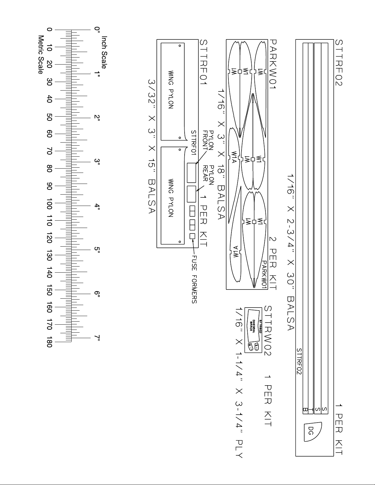
Patterns . . . . . . . . . . . . . . . . . . . . . . . . . . . . . . . . . . 6
Metric Conversions . . . . . . . . . . . . . . . . . . . . . . . . . 6
Metric/Inch Scale. . . . . . . . . . . . . . . . . . . . . . . . . . . 6
BUILD THE TAIL SURFACES . . . . . . . . . . . . . . . . . . . . 7
Build the Fin & Rudder. . . . . . . . . . . . . . . . . . . . . . . 7
Build the Stabilizer & Elevator . . . . . . . . . . . . . . . . . 8
BUILD THE WING . . . . . . . . . . . . . . . . . . . . . . . . . . . . . 9
Build the Wing Panels . . . . . . . . . . . . . . . . . . . . . . . 9
Join the Wing Panels . . . . . . . . . . . . . . . . . . . . . . . 11
BUILD THE FUSELAGE . . . . . . . . . . . . . . . . . . . . . . . 12
Assemble the Fuselage Sides . . . . . . . . . . . . . . . . 12
FINISHING. . . . . . . . . . . . . . . . . . . . . . . . . . . . . . . . . . 14
Final Sanding. . . . . . . . . . . . . . . . . . . . . . . . . . . . . 14
Covering the Model . . . . . . . . . . . . . . . . . . . . . . . . 14
Add Washout. . . . . . . . . . . . . . . . . . . . . . . . . . . . . 14
COMPLETING ASSEMBLY . . . . . . . . . . . . . . . . . . . . . 15
Mount the Stabilizer & Fin . . . . . . . . . . . . . . . . . . . 15
RADIO INSTALLATION . . . . . . . . . . . . . . . . . . . . . . . . 16
Mount the Servos. . . . . . . . . . . . . . . . . . . . . . . . . . 16
ASSEMBLE THE GEAR DRIVE . . . . . . . . . . . . . . . . . . 16
MOUNT THE MOTOR . . . . . . . . . . . . . . . . . . . . . . . . . 17
INSTALL THE PUSHRODS . . . . . . . . . . . . . . . . . . . . . 17
INSTALL THE LANDING GEAR . . . . . . . . . . . . . . . . . 19
SET THE CONTROL THROWS . . . . . . . . . . . . . . . . . . 19
BALANCE YOUR MODEL. . . . . . . . . . . . . . . . . . . . . . 19
PREFLIGHT . . . . . . . . . . . . . . . . . . . . . . . . . . . . . . . . . 20
Charge the Transmitter Batteries . . . . . . . . . . . . . . 20
Identify Your Model . . . . . . . . . . . . . . . . . . . . . . . . 20
Ground Inspection . . . . . . . . . . . . . . . . . . . . . . . . . 20
Range Check . . . . . . . . . . . . . . . . . . . . . . . . . . . . . 20
PERFORMANCE TIPS. . . . . . . . . . . . . . . . . . . . . . . . . 20
Cycle the Batteries. . . . . . . . . . . . . . . . . . . . . . . . . 20
Examine the Propeller . . . . . . . . . . . . . . . . . . . . . . 21
Motor Care . . . . . . . . . . . . . . . . . . . . . . . . . . . . . . 21
Oil the Wheels. . . . . . . . . . . . . . . . . . . . . . . . . . . . 21
Motor Safety Precautions. . . . . . . . . . . . . . . . . . . . 21
AMA Safety Code . . . . . . . . . . . . . . . . . . . . . . . . . 21
Find a Safe Place to Fly . . . . . . . . . . . . . . . . . . . . . 21
FLYING . . . . . . . . . . . . . . . . . . . . . . . . . . . . . . . . . . . . 22
Takeoff . . . . . . . . . . . . . . . . . . . . . . . . . . . . . . . . . . 22
Flight . . . . . . . . . . . . . . . . . . . . . . . . . . . . . . . . . . . 22
Landing . . . . . . . . . . . . . . . . . . . . . . . . . . . . . . . . . 23
ROG Takeoff . . . . . . . . . . . . . . . . . . . . . . . . . . . . . 23
2-VIEW DRAWING. . . . . . . . . . . . . . . . . . . . . back cover
Congratulations and thank you for purchasing the Great
Planes Basic Light Trainer (BLT). The BLT is one in a
series of Park Flyers from Great Planes designed to be
flown in small areas. Park Flyers are a relatively new class
of small, lightweight, slow-flying, fast-building models. Since
Park Flyers are small and fly slowly, little space is required.
A nearby park, schoolyard or vacant lot becomes an
impromptu flying site (see Find a Safe Place to Fly on
page 21). Additionally, Park Flyers are perfect for those
evenings at the field when everybody else is packing up
their gear, the wind has died, and there is still enough light
to fly a small, slow model.
The BLT is a slow flying, high-wing model that is about as
simple to build as they get. However, if you have never
flown an R/C model before, learning to fly the BLT all by
yourself is not recommended. As with any trainer airplane,
you should find an experienced modeler to help you with
your first flights. Information about R/C clubs and instructors
is provided later in this manual.
1. Even though the Great Planes BLT is small, lightweight
and flies slowly , if it is not assembled and operated correctly
it could possibly cause injury to yourself or spectators and
damage property.
2. Build the plane according to the plans and instructions. Do
not alter or modify the model, as doing so may result in an
unsafe or unflyable model. In a few cases the instructions may
differ slightly from the photos. In those instances the plans and
written instructions should be considered as correct.
3. Take time to build straight, true and strong.
4. Use an R/C radio system that is in first-class condition.
This Park Flyer requires micro servos, a micro receiver and
a micro speed control able to handle 5 amps.
5. You must properly install all R/C and other components so
that the model operates properly on the ground and in the air.
6. You must test the operation of the model before every
flight to insure that all equipment is operating, and that the
model has remained structurally sound. Be sure to check
connectors often and replace them if they show signs of
wear or fatigue.
PROTECT YOUR MODEL,YOURSELF
& OTHERS...FOLLOW THESE
IMPORTANT SAFETY PRECAUTIONS
INTRODUCTIONTABLE OF CONTENTS
2
Remember: Take your time and follow directions to end
up with a well-built model that is straight and true.
If you’re an inexperienced modeler, we recommend that
you get assistance from an experienced, knowledgeable
modeler to help you with assembly and your first flights.
You’ll learn faster and avoid risking your model before you’re
truly ready to solo. Y our local hobby shop has information about
flying clubs in your area whose membership includes
qualified instructors.
You can also contact the national Academy of Model
Aeronautics (AMA), which has more than 2,500 chartered
clubs across the country. Through any one of them,
instructor training programs and insured newcomer training
are available.
Contact the AMA at the address or toll-free phone number
below.
Academy of Model Aeronautics
5151 East Memorial Drive
Muncie, IN 47302-9252
Tele. (800) 435-9262
Fax (765) 741-0057
or via the Internet at http://www.modelaircraft.org
Please inspect all parts carefully before starting to
build! If any parts are missing, broken or defective, or if
you have any questions about building or flying this
airplane, please call us at:
(217) 398-8970
or e-mail us at:
productsupport@greatplanes.com.
If you are calling for replacement parts, please
reference the part numbers and the kit number and
have them ready when calling.
This is a list of items required to finish the BLT that must
be purchased separately. For some of these items there
is more than one option which will require a bit of decision
making ahead of time. Order numbers (in parentheses)
are provided for your convenience.
Radio Equipment
The BLT requires a micro receiver and two micro servos.
Futaba
®
S3103 (FUTM0037) or Hobbico®CS-5 (HCAM0090)
micro servos are suitable.
Speed Control
An electronic speed control with BEC (Battery Eliminator
Circuitry) is required. The BEC allows both the motor and the
radio system to be powered by the same battery (thus
eliminating an additional battery typically required to power
the radio). The Great Planes ElectriFly
™
C-5 Nano High
Frequency Electronic Speed Control (GPMM2000) is
recommended for the BLT. If you purchase the complete
motor and gear drive system, the speed control is included
(refer to the “Motor System” section that follows).
Motor System
The BL T is designed to use the Great Planes ElectriFly T280GD ESC motor system and gear drive for electric
flight (GPMG0430). This system includes a T-280 Ferrite
Motor, S-280 4.1:1 ratio gearbox, 3mm prop adapter,
APC 10 x 4.7 Slow Fly propeller and the ElectriFly C-5
Nano High Frequency Electronic Speed Control w/BEC.
The same components are also available without the
speed control by ordering number GPMG0445.
Battery recommendations
There are mainly two kinds of battery packs used for
electric R/C models; nickel-metal hydride (NiMh) packs,
and nickel-cadmium (NiCd, pronounced ny-cad) packs.
NiMh batteries are recommended for the BLT because
they provide nearly twice the capacity of a NiCd for their
size. However, it should be noted that nickel-metal
hydrides cannot be charged as fast as NiCds.
Each individual cell that makes up a battery is 1.2 volts.
Simply stated, a volt is the amount of power a battery
pack can deliver (a 6-cell battery pack is 7.2 volts).
Batteries are also rated by their capacity in mAh (milliAmp-hours), or how much energy they store. A 550 mAh
battery can supply 1 Ampere for .55 hours (about
30-minutes). A 1200 mAh battery pack is about twice the
size of a 550 mAh battery pack. These are the battery
packs recommended for the BLT:
Panasonic 6-cell 550 mAh NiMh pack (GPMP0100) for
beginners due to its light weight.
Panasonic 7-cell 550 mAh NiMh pack (GPMP0101) for
advanced pilots who are capable of flying in slightly
windier conditions. (Continued on page 4)
DECISIONS YOU MUST MAKE
NOTE: We, as the kit manufacturer, provide you with a
top quality kit and great instructions, but ultimately the
quality of your finished model depends on how you build
it; therefore, we cannot in any way guarantee the
performance of your completed model, and no
representations are expressed or implied as to the
performance or safety of your completed model.
3
4
In addition to the equipment listed in the “Decisions You
Must Make” section, following is the “short list” of the most
important building supplies required to build the BLT. We
recommend Great Planes Pro™ CA and Epoxy glue.
❏ 1/2 oz. Thin Pro CA (GPMR6001)
❏ 1/2 oz. Medium Pro CA+ (GPMR6007)
❏ Hobby knife (HCAR0105)
❏ #11 blades (HCAR0211)
Building Supplies
ADDITIONAL ITEMS REQUIRED
Note: The period required to charge the batteries in the
examples above is for discharged batteries. If the battery
you are going to charge is not discharged, connect it to
the motor on your model. Run the motor until the
propeller is turning slowly, thus discharging the battery.
Covering
There are several types of covering that may be used on
the BLT, and a few that are not recommended. Use a
covering suitable for lightweight models. Top Flite
®
EconoKote®and Coverite™Micafilm are suitable for the
BLT. EconoKote is similar to MonoKote (used on most
regular-size sport models), except EconoKote is lighter
and does not shrink as tightly, thus making it suitable for
lightweight structures such as that of the BLT. EconoKote
also has an adhesive on the back which is activated by
the heat of a model airplane covering iron.
Coverite Micafilm is another covering suitable for
lightweight structures. Micafilm has fibers imbedded in
the film and is exceptionally strong, yet remains
lightweight because it has no adhesive on the back.
Therefore, you must apply an adhesive to the structure
before application. Use Coverite Balsarite (COVR2500)
for Micafilm. Do not use Balsarite “film formula” to apply
Micafilm.
Transparent MonoKote film is also suitable for covering
the BL T, because it is lighter and does not shrink as tightly
as opaque MonoKote film (and is the covering that is on
the model featured on the box label). Opaque MonoKote
film is not recommended for the BLT because it is too
heavy and shrinks too tightly for the structure to withstand
the pressure.
Building board
You will need a flat board to lay over your workbench that
you can stick pins into. The back of a 2’ x 4’ ceiling tile or a
section cut from a sheet of Celotex insulation board is ideal.
Panasonic 7-cell 1200 mAh NiMh (GPMP0300) for
advanced pilots requiring the longest duration (not
recommended for beginners due to the fact that it is
heavier than the 550 mAh batteries). Note: If flying the
BLT at altitudes of 3,000 feet above sea level or higher,
beginners should select the 7-cell 550 mAh battery pack,
as the 6-cell pack may not provide adequate power.
ATTENTION: The product you have
purchased is powered by a
rechargeable battery. At the end of its
useful life, under various state and
local laws, it may be illegal to dispose
of this battery into the municipal waste
system. Check with your local solid
waste officials for details in your area
for recycling options or proper
disposal.
This product contains a chemical known to the State
of California to cause cancer and birth defects or
other reproductive harm.
Chargers
The best type of charger to use is a peak charger,
because it charges the batteries until they are fully
charged, then automatically switches to a trickle charge
mode. The Great Planes ElectriFly Peak Charger
(GPMM3000) is suitable for nickel-metal hydride
batteries, NiCds and transmitter battery packs.
If you have another type of charger that is not a peak
charger, you will have to calculate the length of time it
takes to charge the batteries yourself, then turn the
charger off when the batteries are fully charged.
Overcharging the batteries may damage them. Before
you can calculate the time it takes to charge a battery
pack, you first have to know the charge rate you are
going to use. Nickel-metal hydrides must be charged at a
rate of no more than 1/10 of their capacity. For the 550
mAh batteries recommended for the BLT, this would be a
charge rate of approximately 50 mAh. Divide the capacity
of the battery pack by the charge rate to calculate the
charge time. A discharged 550 mAh battery pack charged
at 50 mAh will take 11 hours to charge.
Charge rate/time recommendations:
Charge the 6-cell 550 mAh battery pack at 50 mAh for 1 1 hours.
Charge the 7-cell 550 mAh battery pack at 50 mAh for 1 1 hours.
Charge the 7-cell 1200 mAh battery pack at 100 mAh for 12 hours.
IMPORTANT: Monitor the temperature of the battery
frequently. If the battery becomes warm, disconnect it
from the charger.
A Hobbico R/C Multi-Charger (HCAP0100) is suitable for
charging the battery packs used in the Park Flyers.
❏ Single-edge razor blades (HCAR0212)
❏ Small T-pins (HCAR5100)
❏ Builder’s triangle (HCAR0480)
❏ Small Phillips and flat blade screwdrivers
❏ Pliers with wire cutter (HCAR0630)
❏ Great Planes Plan protector (GPMR6167) or wax paper
❏ Sanding tools and sandpaper assortment
❏ Sealing Iron (TOPR2100)
❏ Double-sided foam tape (GPMQ4440)
Here is a list of optional tools mentioned in the manual that
will help you build the BLT.
❏ Great Planes CG Machine™(GPMR2400)
❏Top Flite Precision Magnetic Prop Balancer™(TOPQ5700)
❏ Top Flite Hot Sock™iron cover (TOPR2175)
❏ Straightedge with scale (HCAR0475)
❏ Cutting mat (HCAR0456)
❏ Masking Tape (TOPR8018)
❏ CA Debonder (GPMR6039)
❏ CA Applicator tips (GPMR6033)
❏ Great Planes 5-1/2” [140mm] Bar Sander (GPMR6169)
and 150-grit adhesive back sandpaper (GPMR6183)
❏ Top Flite 320-grit sandpaper (TOPR8030) and 400-grit
sandpaper (TOPR8032)
For the best performance, the BLT must be built light. One
of the best ways to insure light weight is to build neatly and
make good-fitting glue joints that require less glue. Here are
some tips to help you build neatly and light.
1. The easiest way to cut balsa sticks is with a single-edge
razor blade. To do so, position the stick over the plan, then
place the razor blade on the stick where you wish to cut it.
Press down lightly on the razor blade to make a mark where
the stick is to be cut.
2. Take the stick off the plan and cut it over a cutting mat or
a scrap piece of wood (Okay, if you’re careful you could go
ahead and cut the stick right over the plan, but if you do, you
may cut through the plan protector allowing the CA to soak
through and glue the structure to the plan).
3. Because of the small balsa sticks used in the tail, only where
necessary, we recommend using small T-pins (HCAR5100) or
small straight pins found in craft stores. Do not stick pins into
the sticks near the ends, or the wood may split.
4. If you have difficulty with the T-pins splitting the small
sticks, an alternate method is to use the “crossed-pin”
technique. Insert the T-pins into the building board in a
criss-cross fashion to hold the sticks to the plan.
5. Only a small amount of CA should be used to glue the parts
together. Use the included CA applicator tips to control and
pinpoint the amount of CA that comes from the bottle. When
the tip becomes clogged, cut a short length of the tip off and
continue. In addition to unnecessary weight, excess CA is
difficult to sand. If you require additional CA tips, order no.
GPMR6033 (5).
6. When applying CA, be careful to not glue your fingers to the
structure. In the process of unsticking your fingers you can
inadvertently damage the structure, thus requiring repairs and
adding additional weight (not to mention the aggravation!).
7. Sanding requires a light touch to avoid damage. We
found the best method for sanding is to use light strokes in
the direction of the longest sticks. Be certain the sandpaper
is thoroughly bonded to the bar sander. Lifted edges will
catch the structure, causing damage. Use medium-grit
sandpaper such as 150 or 220.
8. One of the best ways to insure a lightweight model is to
proceed slowly and build neatly. Good glue joints with minimal
adhesive are stronger, lighter and have a better appearance
than poor-fitting joints with too much CA. Of course, you should
take this approach with all of your projects!
9. Work over a flat surface. Cover the plans with Great
Planes Plan Protector (GPMR6167) or wax paper so the
parts will not adhere to the plan.
IMPORTANT BUILDING NOTES
Optional Supplies and Tools
5
6
PATTERNS
1/64" = .4mm
1/32" = .8mm
1/16" = 1.6mm
3/32" = 2.4mm
1/8" = 3.2mm
5/32" = 4mm
3/16" = 4.8mm
1/4" = 6.4mm
3/8" = 9.5mm
1/2" = 12.7mm
5/8" = 15.9mm
3/4" = 19mm
1" = 25.4mm
2" = 50.8mm
3" = 76.2mm
6" = 152.4mm
12" = 304.8mm
15" = 381mm
18" = 457.2mm
21" = 533.4mm
24" = 609.6mm
30" = 762mm
36" = 914.4mm
METRIC CONVERSION
1" = 25.4mm (conversion factor)
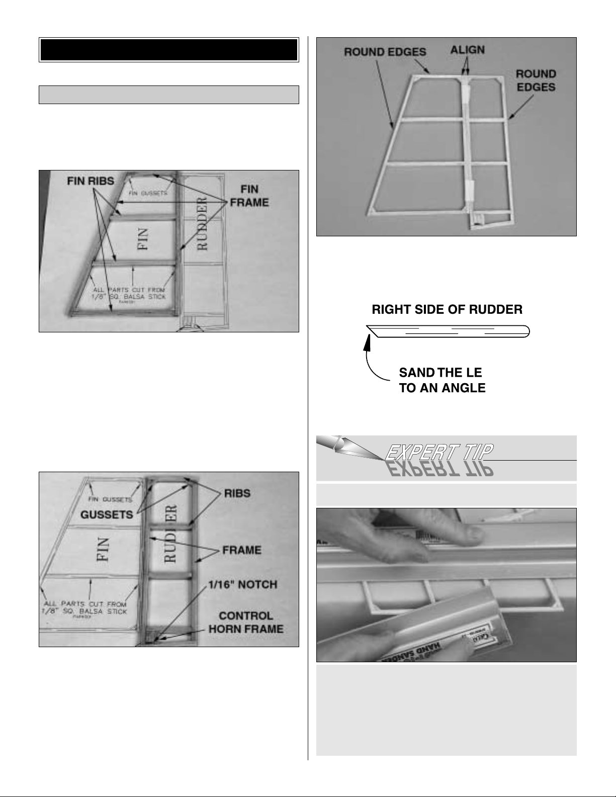
❏ 1. Cover the fin/rudder portion of the plan with wax paper
or Great Planes Plan Protector.
❏2. From the 1/8” x 1/8” x 24” (3.2mm x 3.2mm x 609.6mm)
balsa sticks, cut and glue the fin frame, fin ribs and fin
gussets together over the plan.
❏ 3. Remove the fin from your building board. Using a sanding
bar with 220-grit sandpaper, very lightly sand the fin all over.
Be sure to sand in the direction of the longest sticks.
❏ 4. From the 1/8” x 1/8” x 24” (3.2mm x 3.2mm x 609.6mm)
balsa sticks, cut and glue together the rudder frame, ribs,
control horn frame and corner gussets. Use a hobby knife
to cut the 1/16” (1.6mm) notch for the rudder control horn.
❏ 5. Remove the rudder from your building board. Using a
sanding bar with 220-grit sandpaper, very lightly sand the fin
all over. Be sure to sand in the direction of the longest sticks.
❏ 6. Tape the leading edge of the rudder to the trailing edge
of the fin so that the fin and rudder align at the top. Use a
sanding bar with 220-grit sandpaper to round the leading
edge of the fin, the top of the fin and rudder and the trailing
edge of the rudder.
❏ 7. Remove the rudder from the fin and sand the LE of the
rudder at an angle as shown.
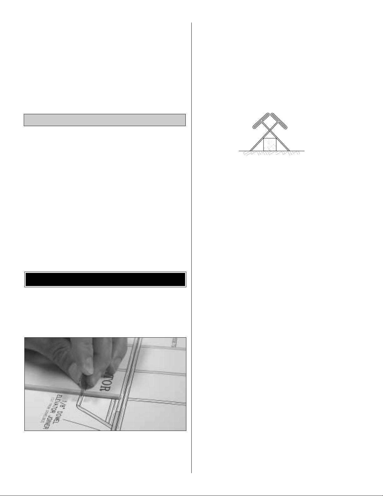
An easy method to hold the delicate tail pieces while
sanding the edges is to place the edge of the tail piece
over the end of your building table. Position a second
sanding bar on top of the tail piece, approximately 1"
(25.4mm) back from the edge. The tail piece can now be
held evenly and securely by applying slight pressure on
the sanding bar.
HOW TO HOLD DELICATE PIECES FOR SANDING
Build the Fin & Rudder
BUILD THE TAIL SURFACES
7
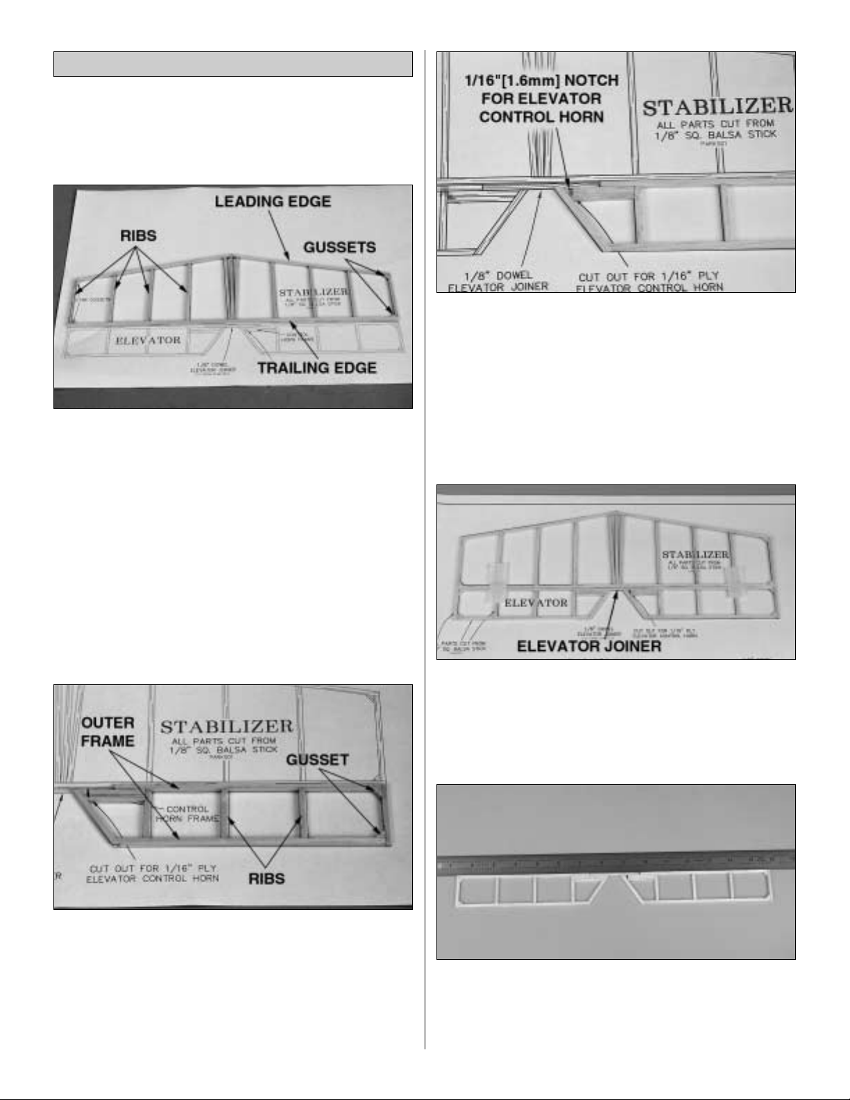
❏ 1. Cover the stabilizer/elevator portion of the plan with
wax paper or Plan Protector.
❏ 2. From the 1/8” x 1/8” x 24” (3.2mm x 3.2mm x 609.6mm)
balsa sticks, cut and glue together the stabilizer trailing
edge, leading edge, ribs and corner gussets.
❏ 3. Remove the stab from your building board. Using a
sanding bar with 220-grit sandpaper, very lightly sand the
stabilizer all over. Be sure to sand in the direction of the
longest sticks.
❏❏4. From the 1/8” x 1/8” x 24” (3.2mm x 3.2mm x
609.6mm) balsa sticks, cut and glue together the outer
frame, ribs and corner gussets of one of the elevators.
❏ 5. Repeat step 4 to build the second elevator half.
❏ 6. In the right elevator half, use a hobby knife to cut the
1/16” (1.6mm) notch for the elevator control horn.
❏ 7. Tape the two elevator halves to the trailing edge of the
stabilizer, aligning the ends of the elevators with the ends of
the stabilizer.
❏ 8. From the 1/8" x 24" (3.2mm x 609.6mm) hardwood
dowel, cut an elevator joiner to fit between the two
elevator halves.
❏ 9. Remove the elevators from the stabilizer and position
the elevator halves and the 1/8" (3.2mm) dowel against a
straightedge. With the leading edge of the elevator halves
and the dowel straight and flat against your building table,
glue the dowel to the elevator halves.
Build the Stabilizer & Elevator
8
 Loading...