

Page 1
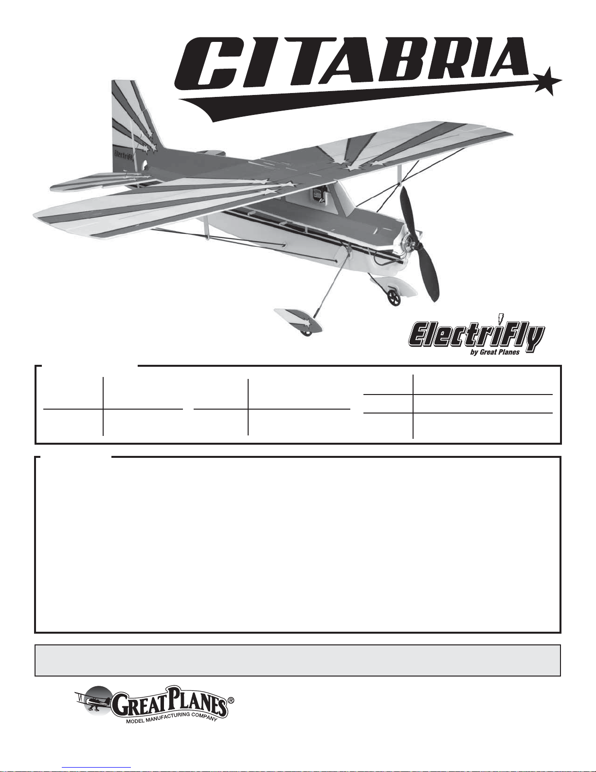
INSTRUCTION
MANUAL
SPECIFICATIONS
Wingspan:
Wing Area: 243 in
33 in
[840 mm]
2
[15.7 dm2]
WARRANTY
Great Planes® Model Manufacturing Co. guarantees this kit to
be free from defects in both material and workmanship at the
date of purchase. This warranty does not cover any component
parts damaged by use or modification. In no case shall Great
Planes’ liability exceed the original cost of the purchased kit.
Further, Great Planes reserves the right to change or modify this
warranty without notice.
In that Great Planes has no control over the final assembly or
material used for final assembly, no liability shall be assumed nor
accepted for any damage resulting from the use by the user of
the final user-assembled product. By the act of using the
user-assembled product, the user accepts all resulting liability.
If the buyer is not prepared to accept the liability associated
with the use of this product, the buyer is advised to return
Weight:
Wing
Loading:
6.0 – 6.3 oz
[170 –180 g]
3.6 – 3.7 oz/ ft
[11 g/dm2]
®
Length: 29.5 in [750 mm]
Radio: 4- channel
2
this kit immediately in new and unused condition to the
place of purchase.
To make a warranty claim send the defective part or item to
Hobby Services at the address below:
Include a letter stating your name, return shipping address, as
much contact information as possible (daytime telephone
number, fax number, e-mail address), a detailed description of
the problem and a photocopy of the purchase receipt. Upon
receipt of the package the problem will be evaluated as quickly
as possible.
Motor: RimFire
outrunner brushless motor
Hobby Services
3002 N. Apollo Dr. Suite 1
Champaign IL 61822 USA
™
250
READ THROUGH THIS MANUAL BEFORE STARTING CONSTRUCTION. IT CONTAINS IMPORTANT
INSTRUCTIONS AND WARNINGS CONCERNING THE ASSEMBLY AND USE OF THIS MODEL.
Entire Contents © 2011 Hobbico,® Inc. All rights reserved.
Champaign, Illinois
(217) 398-8970, Ext 5
airsupport@greatplanes.com
GPMA1127 Mnl
Page 2

TABLE OF CONTENTS
INTRODUCTION . . . . . . . . . . . . . . . . . . . . . . . . . . . . . . . . 2
Academy of Model Aeronautics . . . . . . . . . . . . . . . . . . 2
SAFETY PRECAUTIONS . . . . . . . . . . . . . . . . . . . . . . . . . 2
DECISIONS YOU MUST MAKE. . . . . . . . . . . . . . . . . . . . . 3
Indoor Motor & Battery Recommendations . . . . . . . . . 3
Radio Recommendations. . . . . . . . . . . . . . . . . . . . . . . 3
Charger . . . . . . . . . . . . . . . . . . . . . . . . . . . . . . . . . . . .3
ADDITIONAL ITEMS REQUIRED . . . . . . . . . . . . . . . . . . .3
Adhesives and Building Supplies. . . . . . . . . . . . . . . . . 3
Optional Supplies. . . . . . . . . . . . . . . . . . . . . . . . . . . . . 4
IMPORTANT BUILDING NOTES. . . . . . . . . . . . . . . . . . . . 4
KIT INSPECTION. . . . . . . . . . . . . . . . . . . . . . . . . . . . . . . . 4
KIT CONTENTS. . . . . . . . . . . . . . . . . . . . . . . . . . . . . . . . . 4
BUILD THE FUSELAGE . . . . . . . . . . . . . . . . . . . . . . . . . . 5
Assemble the Fuselage . . . . . . . . . . . . . . . . . . . . . . . . 5
Install the Wing Supports . . . . . . . . . . . . . . . . . . . . . . . 6
Install the Fuselage Doublers. . . . . . . . . . . . . . . . . . . .9
RADIO INSTALLATION. . . . . . . . . . . . . . . . . . . . . . . . . . . 9
Install the Rudder & Elevator Servos . . . . . . . . . . . . . . 9
Adjust the Pushrods. . . . . . . . . . . . . . . . . . . . . . . . . . 11
Install the Aileron Servo . . . . . . . . . . . . . . . . . . . . . . . 12
INTRODUCTION
If you’ve built any of the previous Great Planes Indoor Aerobatic
planes, the Citabria 3D Indoor EP ARF uses the same proven
methods. If this is your fi rst Great Planes Indoor Aerobatic
plane, you will be surprised at how quickly and easily you can
have it in the air. The building crutches make aligning the parts
a non-issue. So let’s get this plane built and go have some fun.
INST ALL THE MOTOR. . . . . . . . . . . . . . . . . . . . . . . . . . .13
BALANCE THE MODEL (C.G.). . . . . . . . . . . . . . . . . . . . 14
GET THE MODEL READY TO FLY . . . . . . . . . . . . . . . . . 15
Check the Control Directions . . . . . . . . . . . . . . . . . . . 15
Set the Control Throws. . . . . . . . . . . . . . . . . . . . . . . . 15
PREFLIGHT. . . . . . . . . . . . . . . . . . . . . . . . . . . . . . . . . . . 16
Identify Your Model. . . . . . . . . . . . . . . . . . . . . . . . . . . 16
Charge the Batteries . . . . . . . . . . . . . . . . . . . . . . . . .16
Balance Propellers. . . . . . . . . . . . . . . . . . . . . . . . . . . 16
Ground Check and Range Check . . . . . . . . . . . . . . .16
MOTOR & BATTERY SAFETY PRECAUTIONS. . . . . . . 16
LITHIUM BATTERY HANDLING & USAGE . . . . . . . . . . 17
AMA SAFETY CODE. . . . . . . . . . . . . . . . . . . . . . . . . . . . 17
General . . . . . . . . . . . . . . . . . . . . . . . . . . . . . . . . . . . 17
Radio Control . . . . . . . . . . . . . . . . . . . . . . . . . . . . . . . 17
CHECK LIST . . . . . . . . . . . . . . . . . . . . . . . . . . . . . . . . . . 17
FLYING. . . . . . . . . . . . . . . . . . . . . . . . . . . . . . . . . . . . . . . 18
Takeoff . . . . . . . . . . . . . . . . . . . . . . . . . . . . . . . . . . . . 18
Flight . . . . . . . . . . . . . . . . . . . . . . . . . . . . . . . . . . . . . 18
Landing . . . . . . . . . . . . . . . . . . . . . . . . . . . . . . . . . . . 18
Or via the Internet at:
http://www.modelaircraft.org
http://www.modelaircraft.org/parkfl yer.aspx
IMPORTANT!!! Two of the most important things you can
do to preserve the radio controlled aircraft hobby are to avoid
fl ying near full-scale aircraft and avoid fl ying near or over
groups of people.
For the latest technical updates or manual corrections to the
Citabria 3D Indoor EP ARF, visit the Great Planes web site
at www.greatplanes.com. Open the “Airplanes” link, then
select the Citabria 3D Indoor EP ARF. If there is new technical
information or changes to this model a “tech notice” box will
appear in the upper left corner of the page.
Academy of Model Aeronautics
If you are not already a member of the AMA, please join! The
AMA is the governing body of model aviation and membership
provides liability insurance coverage, protects modelers’ rights
and interests and is required to fl y at most R/C sites. The AMA
has two classes of membership available: Open membership
or their Park Pilot Program, which this aircraft qualifi es for. The
Park Pilot Program is for people fl ying electric aircraft and
gliders under two pounds and which fl y slower than 60mph.
This will enable you to enjoy most AMA benefi ts and organize
clubs and fl ying sites in more congested areas.
Academy of Model Aeronautics
5151 East Memorial Drive
Muncie, IN 47302-9252
Ph. (800) 435-9262
Fax (765) 741-0057
SAFETY PRE CAUTION S
Protect Your Model, Yourself & Others …
Follow These Important Safety Precautions
1. Your Citabria 3D Indoor EP ARF should not be considered
a toy, but rather a sophisticated, working model that
functions very much like a full-size airplane. Because of its
performance capabilities, the Citabria 3D, if not assembled
and operated correctly, could possibly cause injury to
yourself or spectators and damage to property.
2. You must assemble the model according to the
instructions. Do not alter or modify the model, as doing
so may result in an unsafe or unfl yable model. In a few
cases the instructions may differ slightly from the photos.
In those instances the written instructions should be
considered as correct.
3. You must take time to build straight, true and strong.
4. You must use an R/C radio system that is in good condition,
a correctly sized engine, and other components as specifi ed
in this instruction manual. All components must be correctly
installed so that the model operates correctly on the ground
and in the air. You must check the operation of the model
and all components before every fl ight.
2
Page 3

5. If you are not an experienced pilot or have not fl own this
type of model before, we recommend that you get the
assistance of an experienced pilot in your R/C club for
your fi rst fl ights. If you’re not a member of a club, your
local hobby shop has information about clubs in your area
whose membership includes experienced pilots.
6. Carefully read and follow all the instructions included with
your LiPo battery and battery charger. LiPo batteries are
not forgiving like NiCd or NiMH batteries. Overcharging or
charging the LiPo battery at too high a current will damage
the battery and could damage property.
We, as the kit manufacturer, provide you with a top quality,
thoroughly tested kit and instructions, but ultimately the
quality and fl yability of your fi nished model depends
on how you build it; therefore, we cannot in any way
guarantee the performance of your completed model,
and no representations are expressed or implied as to
the performance or safety of your completed model.
Remember: Take your time and follow the instructions to
end up with a well-built model that is straight and true.
DECISI ONS YOU MUST MAKE
This is a partial list of items required to fi nish the Citabria
3D Indoor EP ARF that may require planning or decision
making before starting to build. Order numbers are provided
in parentheses.
Indoor Motor and
Battery Recommendations
For best indoor fl ight performance, a lightweight battery is
recommended. We recommend:
(1) Great Planes
❍
20C LiPo battery (GPMP0700)
(1) FlightPower
❍
LiPo battery (FPWP4014)
(1) RimFire
❍
(1) ElectriFly
❍
FlightPower 10amp Brushless ESC (FPWM0210)
(1) 8 × 3.5 PowerFlow
❍
Outdoor Motor and Battery Recommendations:
(1) Great Planes Competition Series 11.1 volt 300mAh
❍
20C LiPo battery (GPMP0701)
(1) FlightPower EON-X Lite 11.1 volt 350mAh 25C
❍
LiPo battery (FPWP4015)
(1) RimFire 300 (GPMG4505)
❍
(1) FlightPower 10amp Brushless ESC (FPWM0210)
❍
(1) 8 × 3.5 PowerFlow Propeller (GPMQ6608)
❍
®
Competition Series 7.4 volt 300mAh
®
EON-X™ Lite 7.4 volt 350mAh 25C
™
250 (GPMG4502)
®
8amp Brushless ESC (GPMM1800) or
™
Propeller (GPMQ6608)
Radio Recommendations
A 4-channel radio system is required.
(3) Futaba
❍
(FUTM0414)
(1) Futaba R6004FF Mini Receiver (FUTL7624)
❍
®
S3114 Micro High Torque servos
Charger
A LiPo compatible charger is required to charge LiPo batteries.
The Great Planes ElectriFly PolyCharge4™ is designed for
LiPo packs only; however, it is able to charge four LiPo packs
simultaneously. The ElectriFly Triton2™ and AC/DC Triton2 EQ
chargers will only charge one pack at a time, but are capable
of charging NiCd, NiMH, Pb acid and LiPo batteries. Order
numbers are provided below.
Great Planes PolyCharger4 DC Only 4 Output LiPo
❍
Charger (GPMM3015)
OR
Great Planes ElectriFly Triton2 DC Comp Peak
❍
Charger (GPMM3153)
OR
Great Planes AC/DC Triton2 EQ Charger/Balancer
❍
(GPMM3156)
Throughout the life of a LiPo battery, the individual cells
located inside the battery may become unbalanced. These
unbalanced cells can shorten the life of the battery or cause
it to malfunction. For this reason, it is always recommended
that a cell balancer be used when charging LiPo batteries.
The Electrifl y Equinox™ is a cell balancer that may be used
with any LiPo charger and is capable of maintaining the cell
balance of the battery. Note: The AC/DC Triton2 EQ does
not require a cell balancer.
Great Planes ElectriFly Equinox LiPo Cell Balancer
❍
(GPMM3160)
ADD ITIONAL ITEMS R EQ UI RE D
Adhesives and Building Supplies
This is the list of adhesives and building supplies that are
required to fi nish the Citabria 3D Indoor Foam Plane.
(1) UFO Foam Safe Thin CA 1oz. (HOTR1040)
❍
(1) CA Activator Foam Safe 2oz. pump (GPMR6035)
❍
(1) Hobby Knife with 5 blades (RMXR6900)
❍
(1) Phillips head screwdriver
❍
Hobbico
❍
Straightedge
❍
®
Soldering Iron 30 Watt (HCAR0775)
3
Page 4
Optional Supplies
KIT IN SPE CTIO N
Here are optional tools that will help you build the Citabria 3D.
CA applicator tips (HCAR3780)
❍
CA debonder (GPMR6039)
❍
Precision Magnetic Prop Balancer (TOPQ5700)
❍
Waxed Paper
❍
IMPORTANT BUILDING NOTES
• Photos and sketches are placed before the step they refer
to. Frequently you can study photos in following steps to get
another view of the same parts.
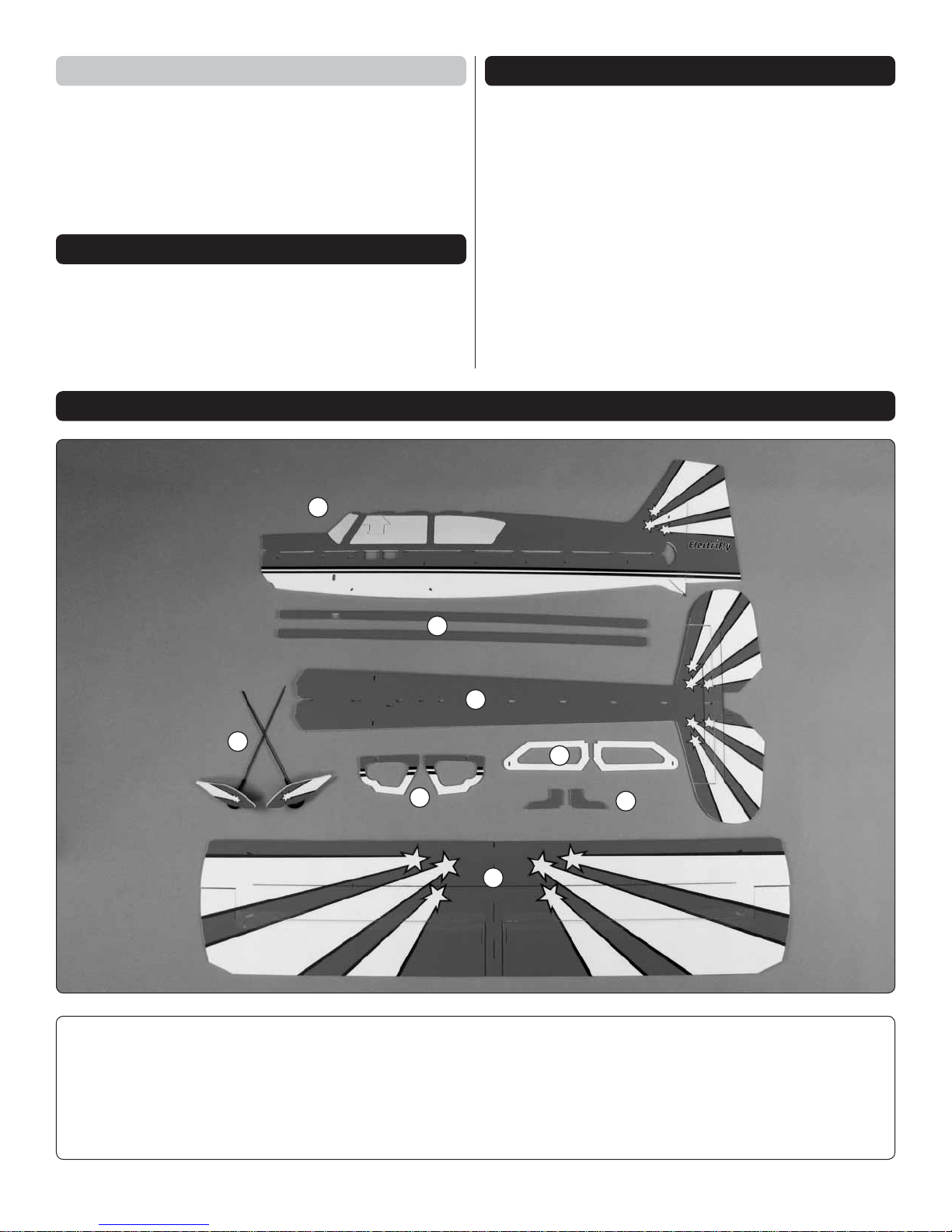
KIT CONTENTS
1
Carefully remove the major parts from the kit. Take an inventory
to make sure it is complete, and inspect the parts to make
sure they are of acceptable quality. If any parts are damaged
or missing or are not of acceptable quality, or if you need
assistance with assembly, contact Product Support. When
reporting defective or missing parts, use the part names
exactly as they are written in the Kit Contents list.
Great Planes Product Support
3002 N Apollo Drive, Suite 1
Champaign, IL 61822
Ph: (217) 398-8970, ext. 5
Fax: (217) 398-7721
E-mail: airsupport@greatplanes.com
4
Kit Contents
5
2
8
1. Vertical Fuselage
2. Horizontal Fuselage
3. Wing
4. Landing Gear
7
6
3
5. Diagonal Support
6. Upper Motor Doubler
7. Horizontal Fuselage Doubler
8. Vertical Fuselage Doubler
4
Page 5
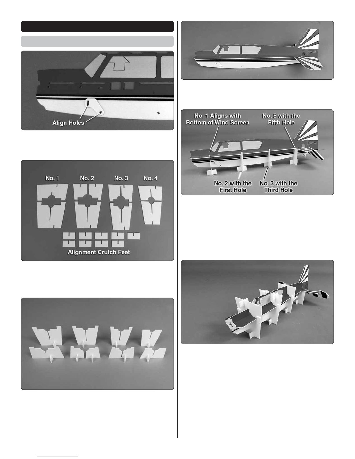
BUILD THE FUSELAGE
Assemble the Fuselage
1. Locate the two ABS landing gear supports. Glue
❏
a landing gear support to each side of the fuselage in the
location shown.
4. Insert the aft end of the horizontal fuselage into the
❏
front of the vertical fuselage. Key the horizontal and vertical
fuselages together.
2. Remove the nine fuselage alignment crutches from
❏
the surrounding foam. Note: Use a sharp hobby knife to cut
the crutch parts from the surrounding foam, trimming the tabs
fl ush with the edges of the crutches.
3. To prevent the parts from adhering to your building table,
❏
place a piece of waxed paper, or the clear plastic bag the
parts came in, on your table. Use foam safe CA to glue the
nine alignment crutch feet to the alignment crutches. Make
sure the crutches and feet are fl at against the building table
and that the crutches are perpendicular to the table.
5. On your building table, place the four bottom crutches
❏
with the feet on them underneath the fuselage in the locations
shown. Crutch #1 is positioned in line with the bottom of the
windscreen. Crutch #2 is positioned at the fi rst hole in the
side of the fuselage. Crutch #3 is positioned at the third hole
in the side of the fuselage. Crutch #4 is positioned at the fi fth
hole in the side of the fuselage, just under the leading edge
of the stabilizer.
6. Test fi t the #1, #2 and #3 top crutches over their
❏
corresponding bottom crutches. Install the ABS motor mount
onto the front of the fi rewall, but DO NOT glue it in place at
this time. Check that all the crutches are seated against the
fuselage and the horizontal and vertical fuselages are keyed
together. Then, glue the top and bottom of crutches #1, #2
and #3 together by applying small amount of foam-safe CA to
the tabs of the crutches. Be careful not to glue the crutc hes
to the fuselage.
7. Position the #4 top crutch over the corresponding #4
❏
bottom crutch.
5
Page 6
8. Make sure the horizontal and vertical fuselages are keyed
❏
together and the crutches are fl at on your building table. Glue
the horizontal and vertical fuselages together by applying thin
foam-safe CA along the joint between the two. Be careful when
gluing around the crutches. DO NOT glue the crutches to the
fuselage. Allow the CA to cure for a few minutes before moving
the plane. The use of foam-safe accelerator will quicken the
curing of the CA, but use it sparingly. Excessive amounts of
accelerator can cause the CA to cure quickly, causing it to
get hot and melt the foam.
and #4 crutches are fl at on the building table. The #2 building
crutch should be fl at on the wing. Check that the horizontal
and vertical fuselages are keyed together. Use foam-safe CA
to glue the bottom of the horizontal and vertical fuselages
together and the wing and vertical fuselage together.
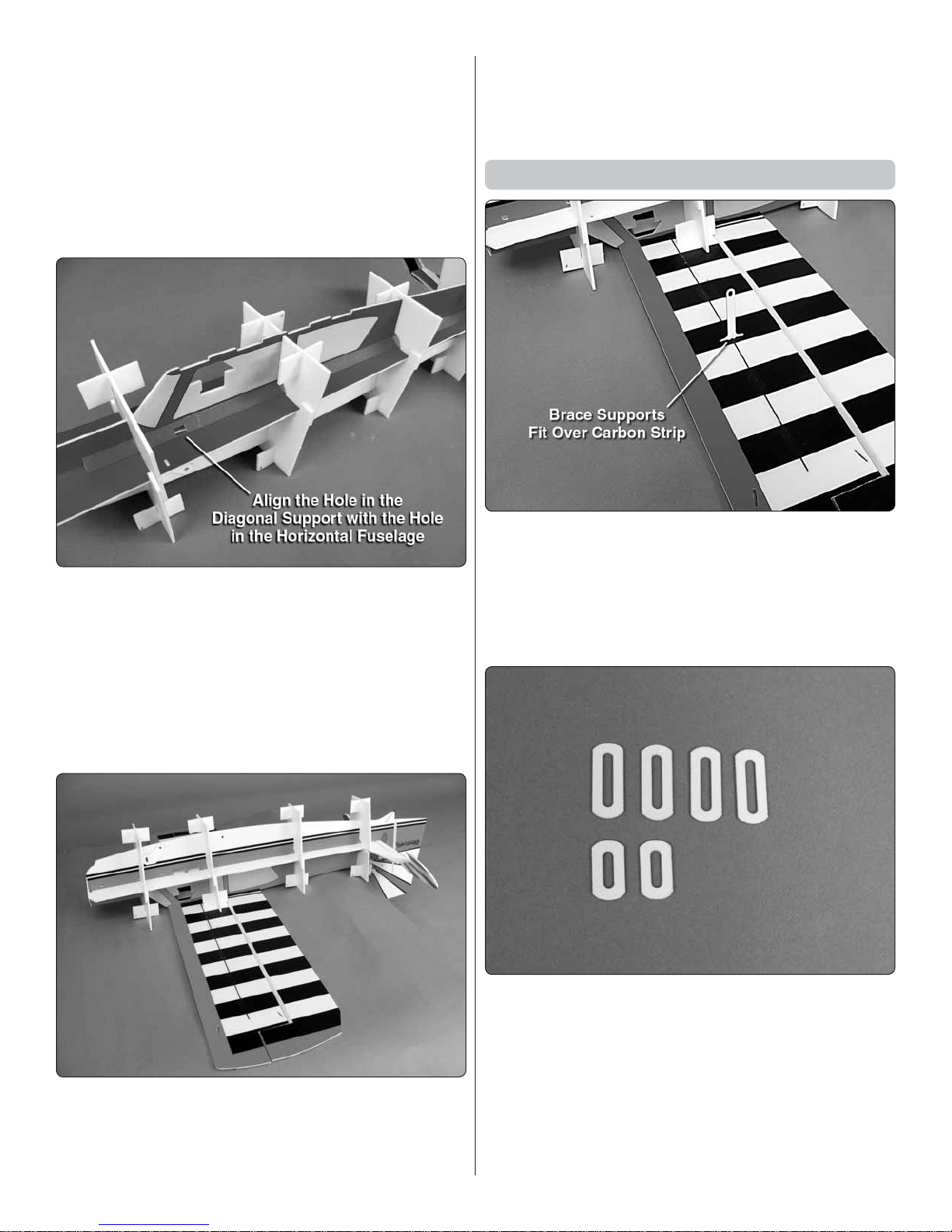
Install the Wing Supports
9. On the left side of the fuselage, from the aft end, slide the
❏
diagonal support with the hole in it, under the crutches. Align
the hole in the diagonal support with the hole in the horizontal
fuselage. Use foam-safe CA to glue the diagonal support at a
45 degree angle against the horizontal and vertical fuselages.
10. Insert and glue the second diagonal support on the
❏
right side of the fuselage. Make sure the aft end of the right
diagonal support is the same distance from the rudder hinge
line as the left diagonal support.
1. Locate the two ABS brace supports. There is a slot
❏
located in the center of each wing. Glue the ABS brace
supports into the slots, perpendicular to the underside of the
wing. It is possible that, during manufacturing, some glue
may have gotten into the slot. If this has happened, DO NO T
FORCE the supports into the slot. Use a sharp hobby knife
to remove any excess glue.
11. Place the wing upside down on the building table.
❏
Carefully turn the Citabria over and key the top of the fuselage
into the bottom of the wing. Note that the vertical fi n will need
to hang over the edge of the building table. Check that #1, #3
2. Locate the four long and two medium ABS brace
❏
doublers
Note: For steps 3 through 5, DO NOT glue the parts until
told to do so.
6
Page 7

3. Slide one of the long brace doublers onto a 2 x 390mm
❏
carbon rod. Slide the carbon rod through the brace support
in the wing and into the small hole in the landing gear support.
With the long brace doubler on the carbon rod, insert the
other end of the carbon rod in the slot at the tip of the wing.
The carbon rod should go through the long brace doublers
and into the wing.
4. Slide a second long brace doubler onto another 2 x
❏
390mm carbon rod. Slide the carbon rod through the brace
support. Slide a medium brace doubler on the rod and then
insert the end of the rod in the slot in the bottom of the vertical
fuselage. Insert the other end of the rod in the slot at the tip
of the wing.
5. Go back to step 3 and install the carbon rods on the other
❏
side of the fuselage. Check that all the carbon rods are straight.
7
Page 8

6. Check that all the carbon rods and brace doublers are
❏
in position and straight and the crutches are in position and
fl at on the building table. Start by gluing the carbon rod and
the long brace doubler to the wing at the wing tip.
7. Next check that everything is still straight and glue the
❏
carbon rod to the landing gear support.
9. Once the glue has cured, glue the carbon rods to the
❏
brace supports.
10. Turn the fuselage upright and position it on the crutches.
❏
Slide two ABS small brace doublers onto a 1 x 90mm
carbon rod. Insert the carbon rod in the slot in the top of the
stabilizer and the side of the vertical fi n.
8. Position the medium brace doublers so that both carbon
❏
rods pass through the brace doubler. Glue the brace doubler
and carbon rod to the vertical fuselage.
11. Insert the carbon rod and brace doublers on the other
❏
side of the fi n and stabilizer.
12. Check that the stabilizer and fi n are perpendicular to
❏
each other. Glue the carbon rods and brace doublers to the
stabilizer and fi n.
8
Page 9

Install the Fuselage Doublers
1. Remove the motor mount and glue the upper motor
❏
doubler to the front of the vertical fuselage. The front of the
upper motor doubler should be fl ush with the front of the
fuselage.
4. Glue the two vertical fuselage doublers to the front of
❏
the fuselage. Make sure they are fl ush with the front of the
fuselage and against the horizontal fuselage doubler.
2. Turn the plane upside down. Use a sharp hobby knife
❏
to carefully cut the #1, #2 and #3 bottom crutches from the
top crutches.
5. Glue the ABS motor mount to the front of the fuselage.
❏
Apply a bead of glue to the joint on all sides of the fuselage
and motor mount. Take note of the orientation of the three
large holes.
RADI O I NSTALLATION
Install the Rudder & Elevator Servos
3. Glue the two horizontal fuselage doublers to the front
❏
of the fuselage. Make sure they are fl ush with the front of the
fuselage and against the vertical fuselage.
1. Use foam-safe CA to glue the elevator servo offset
❏
around the forward servo mounting hole on the left side
of the fuselage.
9
Page 10

2. Connect the elevator servo to your receiver. Remove the
❏
servo screw from the servo and install a large servo arm onto
the servo. Center the trims on the transmitter. Position the
servo arm so that one arm is perpendicular to the centerline
of the servo as shown. Use diagonal pliers to remove the
three extra servo arms.
3. Install the elevator servo in the forward servo hole with
❏
the output shaft towards the front of the fuselage. Glue the
servo in place with foam-safe CA. Be careful not to get any
glue inside the servo case.
5. Install the pre-assembled elevator pushrod by inserting
❏
the ABS pushrod guides through the fuselage as shown. DO
NOT glue the pushrod guides in place at this time.
6. Insert the rudder pushrod from the front, through the
❏
fi ve pushrod guides. The z-bend should be next to the rudder
servo arm.
4. Center the servo arm on the rudder servo and trim off
❏
the extra servo arms. Use foam-safe CA to glue the rudder
servo, with the output shaft forward, in the aft servo hole on
the left side of the fuselage.
7. Remove the elevator servo arm and insert the z-bend
❏
into the outer hole of the arm, approximately 5/8” [16mm]
from the center of the servo arm. Note: If you are not using
a computer radio, and do not wish to set your model up with
3D control throws, you will need to insert the z-bend in a hole
closer to the center of the servo arm. The z-bend should be
installed so that the pushrod is on the back side of the servo
10
Page 11

arm, closest to the fuselage. Center the servo and reinstall
the servo arm onto the servo, securing it with the servo screw.
8. Insert the z-bend in the elevator control horn. Insert the
❏
control horn in the slot in the elevator. The notch in the control
horn should slide over the carbon fi ber strip in the elevator.
If the control horn will not fi t over the carbon fi ber strip, use
a sharp hobby knife to remove the excess glue from the slot.
DO NOT glue the horn to the elevator until told to do so.
9. Remove the servo arm from the rudder servo and insert
❏
the z-bend in the outer hole of the servo arm. The pushrod
should be to the outside of the servo arm, away from the
fuselage. Re-install the servo arm screw in the servo.
of the z-bend wire into the heat shrink and install the rudder
control horn in the rudder. Note: The rudder hinge tape may be
covering the front of the rudder control horn slot. Use a sharp
hobby knife to trim the tape from the slot. Secure the z-bend
wire to the rudder pushrod by shrinking the heat shrink tubing
using a soldering iron. Be careful when using the soldering
iron close to the foam. The foam will melt if it is touched with
the hot soldering iron.
Adjust the Pushrods
1. With the transmitter and receiver switched on and the
❏
elevator servo centered, make sure that the elevator control
horn is seated against the elevator. Check that the elevators
are centered. If they are not, you will need to adjust the length
of the z-bend.
PUSHROD LENGTH ADJUSTMENT
For your convenience,
the aileron and elevator
pushrods have been preassembled. If you are not
using a Futaba S3114
servo, or due to manufacturing tolerances, it may
be necessary to change
the pushrod length. This
may be done by holding
the heat shrink tubing that
connects the pushrod to
the z-bend and gently rotating the z-bend until the
glue holding the z-bend
breaks loose. Then, adjust
the length by pulling or
pushing the z-bend until
the appropriate length is
achieved. Re-glue the zbend to the pushrod using
a drop of thin CA. Be careful that the CA does not
run down the pushrod and
into the pushrod guides.
10. Slide the black heat shrink tubing over the aft end
❏
of the rudder pushrod. Insert the z-bend wire into the hole in
the rudder contr ol horn from the bottom. Slide the other end
2. Once the elevator is centered, apply a bead of foam-
❏
safe CA along the joint between the elevator control horn
and the elevator.
3. Use foam-safe CA to glue the rudder control horn to
❏
the rudder.
4. Adjust the length of the pushrod so that when the rudder
❏
servo is centered, the rudder is centered.
5. Apply a drop of thin CA to the end to the heat shrink to
❏
further secure the z-bend to the pushrod.
11
Page 12

6. Operate the rudder and elevator, checking that the
❏
pushrods do not bind in the pushrod guides. Adjust the position
of the pushrod guides so that the pushrods are straight and
the guides are 90 degrees to the fuselage. Glue the pushrod
guides to the fuselage with foam-safe CA.
Install the Aileron Servo
arm, you may need to drill a pilot hole with a #60 [1mm] drill
bit in the servo arm that will align with the mounting holes in
the servo arm extension.
3. Attach the servo arm extension to the servo arm using
❏
two 3/64” [1.2mm] self tapping screws.
1. Use foam-safe CA to glue the aileron servo doubler to
❏
each side of the fuselage.
2. Connect the aileron servo to the receiver and center
❏
the servo arm. Place the ABS servo arm extension on the
underside of the servo arm. If you are using Futaba servo arms,
the holes in the servo arm and the holes in the servo arm
extension will align. If you are using another brand of servo
4. Install the aileron servo arm on the aileron servo. Make
❏
sure the servo arm is centered. Once the servo is installed,
removal of the servo arm is diffi cult.
5. Use foam-safe CA to glue the aileron servo to the
❏
fuselage. Make sure the aileron servo wire is on the right
side of the fuselage.
12
Page 13

6. Insert the z-bend of both aileron pushrods in the aileron
❏
servo extension.
7. Insert an ABS aileron control horn onto the end of both
❏
aileron pushrods. Insert the aileron control horns in the slot in
both ailerons. With the transmitter switched on and the aileron
servo arm centered, check that both ailerons are centered.
If they are not, adjust the length of the aileron pushrods as
needed. Then, glue the aileron control horns in the aileron.
Again, check that the ailerons are centered and apply a drop
of thin CA to the end of the heat shrink tubing.
2. Insert the landing gear through the landing gear support
❏
and into the horizontal fuselage. Be careful not to push the
landing gear all the way through the horizontal fuselage. The
end should be fl ush with the top of the horizontal fuselage.
If it is diffi cult to insert both landing gear legs through the
landing gear support, use a hobby knife to enlarge the hole
slightly. Rotate the wheels so that they are parallel to each
other. Apply foam-safe CA to the joint between the landing
gear support and the landing gear legs and the horizontal
fuselage and the landing gear legs.
3. Place a small piece of loop (soft) side of the self adhesive
❏
hook and loop material to the back of the ESC and the receiver.
INSTALL THE MOTO R
1. Install the motor to the motor mount using the included
❏
#2 x 3/8” [9.5mm] self-tapping screws.
4. Place a piece of hook (rough) material under the
❏
fuselage, close to the front. Route the motor leads through
the fuselage and connect them to the motor. Attach the ESC
to the hook material.
13
Page 14

5. Connect the servos to the receiver so that the wires do
❏
not interfere with any of the pushrods. Note that holes have
been provided to route the elevator and aileron servo wires
to the bottom right side of the fuselage.
6. Position the receiver under the horizontal fuselage as far
❏
aft as possible. Make sure the servo wires do not interfere with
the pushrods. Apply a piece of hook material on the bottom
of the horizontal fuselage, at the receiver location. Attach the
receiver to the fuselage. To prevent the wires from interfering
with the pushrods, use a small piece of tape to attach them
to the fuselage.
BALANCE THE MODEL ( C.G.)
More than any other factor, the C.G. (center of gravity/
balance point) can have the greatest effect on how a model
fl ies and could determine whether or not your fi rst fl ight will
be successful. If you value your model and wish to enjoy it
for many fl ights, DO NOT OVERLOOK THIS IMPORTANT
PROCEDURE. A model that is not properly balanced may
be unstable and possibly unfl yable.
Because the Citabria 3D Indoor EP ARF is an indoor lightweight
plane, adding weight to balance the plane is not an option. At
this stage the model should be in ready-to-fl y condition with all
of the components in place except the motor battery. The motor
battery will be moved forward and aft to balance the plane.
7. Install the propeller on the motor following the motor
❏
instructions.
Hint: The rubber o-ring can be diffi cult to stretch over the
screw, then the propeller and over the other screw. A small
jewelers phillips head screwdriver can be used to pry the
rubber o-ring over the screws and propeller. Be careful not
to allow the screwdriver to slip and damage the windings
inside the motor.
1. Use a fi ne-point felt tip pen to mark lines on the bottom of
❏
the wing, 1-15/16” [49mm] from the leading edge of the wing,
on both sides of the fuselage. Apply narrow (1/16” [1.5mm]
strips of tape over the lines so you will be able to feel them
when lifting the model with your fi ngers.
This is where your model should balance for the fi rst fl ights.
Later, you may experiment by shifting the C.G. 5/16” [8mm]
forward or aft to change the fl ying characteristics. Moving
the C.G. forward will improve the smoothness and stability,
but the model will then be less aerobatic (which may be fi ne
for less-experienced pilots). Moving the C.G. aft makes the
model more maneuverable and aerobatic for experienced
pilots. In any case, start at the recommended balance
point and do not at any time balance the model outside
the specifi ed range.
2. Place the motor battery on the top of the fuselage aft of
❏
the recommended C.G. Lift the model from the bottom at the
recommended C.G.
3. If the tail drops, the model is “tail heavy”. Move the motor
❏
battery forward to get the model to balance. If the nose drops,
the model is “nose heavy”. Move the motor battery aft. Once
you have determined the battery location required to balance
the plane, note the location where the battery would need to
be attached on the bottom of the horizontal fuselage.
14
Page 15

4. Apply the remaining hook and loop material to the bottom
❏
of the horizontal fuselage at the approximate location for the
motor battery. Attach an opposite piece of hook and loop
material to the battery. Trial fi t the motor battery to the bottom
of the fuselage and recheck the C.G.
Set the Control Throws
To ensure a successful fi rst fl ight, set up your Citabria 3D
according to the control throws specifi ed in this manual.
The throws have been determined through actual fl ight
testing and accurate record-keeping, allowing the model
to perform in the manner in which it was intended. If, after
you have become accustomed to the way the Citabria
3D fl ies, you would like to change the throws to suit your
taste, that is fi ne. However, too much control throw could
make the model too responsive and diffi cult to control, so
remember, “more is not always better.”
1. Use a box or something similar to prop up the bottom
❏
of the fuselage so the horizontal stabilizer and wing will
be level.
2. Measure the 3D elevator throw fi rst. Hold a ruler vertically
❏
on your workbench against the widest part (front to back) of
the trailing edge of the elevator. Note the measurement on
the ruler.
GET THE MODEL READY TO FLY
Check the Control Directions
1. Remove the propeller and switch on the
❏
transmitter and connect the motor battery. Check
all the control surfaces to see if they are centered.
4-CHANNEL RADIO SET UP (STANDARD MODE 2)
RUDDER
MOVES
RIGHT
FULL
THROTTLE
2. Make certain that the control surfaces respond in the
❏
correct direction as shown in the diagram. If any of the controls
respond in the wrong direction, use the servo reversing in the
transmitter to reverse the servos connected to those controls.
Be certain the control surfaces have remained centered. Adjust
if necessary.
RIGHT AILERON
MOVES UP
LEFT AILERON
MOVES DOWN
ELEVATOR
MOVES DOWN
3. Move the elevator up with your transmitter and move
❏
the ruler forward so it will remain contacting the trailing
edge. The distance the elevator moves up from center is
the “up” elevator throw. Measure the down elevator throw
the same way.
4. Measure and set the high and low rate elevator throws
❏
and the high, low, and 3D rate throws for the rest of the control
surfaces the same way.
If your radio does not have dual rates, we recommend
setting the throws at the high rate settings.
NOTE: The throws are measured at the widest part of
the elevators, rudder and ailerons.
15
Page 16

These are the recommended control surface throws:
Balance Propellers
ELEVATOR
RUDDER
AILERONS
LOW RATE
Up & Down
1-1/4"
[32 mm]
25 deg
Right & Left
1"
[25 mm]
17 deg
Up & Down
3/4"
[19mm]
14 deg
PREFLIGHT
HIGH RATE
Up & Down
1-5/8"
[41mm]
33 deg
Right & Left
1-5/8"
[41mm]
29 deg
Up & Down
1-3/8"
[35mm]
27 deg
3D RATE
Up & Down
2-1/8"
[54 mm]
45 deg
Right & Left
2"
[51mm]
36 deg
Up & Down
2-3/8"
[60 mm]
52 deg
Carefully balance your propeller and spare propellers before
you fl y. An unbalanced prop can be the single most signifi cant
cause of vibration that can damage your model. Vibration of
props on small models can cause a loss of power, but vibration
may also damage your radio receiver, battery and possibly
the motor bearings.
We use a Top Flite® Precision Magnetic Prop Balancer
(TOPQ5700) in the workshop and keep a Great Planes
Fingertip Prop Balancer (GPMQ5000) in our fl ight box.
Identify Your Model
No matter if you fl y at an AMA sanctioned R/C club site or
if you fl y somewhere on your own, you should always have
your name, address, telephone number and AMA number on
or inside your model. It is required at all AMA R/C club fl ying
sites and AMA sanctioned fl ying events (except when fl own
indoors). Fill out the identifi cation tag on page 19 and place
it on or inside your model.
Charge the Batteries
Follow the battery charging instructions that came with your
radio control system to charge the batteries. You should
always charge your transmitter batteries the night before
you go fl ying, and at other times as recommended by the
radio manufacturer.
CAUTION: Unless the instructions that came with your
radio system state differently, the initial charge on new
transmitter batteries should be done for 15 hours using
the slow-charger that came with the radio system.
This will “condition” the batteries so that the next charge
may be done using the fast-charger of your choice. If the
initial charge is done with a fast-charger the batteries may
not reach their full capacity and you may be fl ying with
batteries that are only partially charged.
Ground Check and Range Check
Always ground check the operational range of your radio
before the fi rst fl ight of the day following the manufacturer’s
instructions that came with your radio. This should be done
once with the motor off and once with the motor running
at various speeds. If the control surfaces do not respond
correctly, do not fl y! Find and correct the problem fi rst. Look
for loose servo connections or broken wires, corroded wires
on old servo connectors, poor solder joints in your battery
pack or a defective cell, or a damaged receiver crystal from
a previous crash.
MOTOR AND BATTERY
SAFETY PRE CAUTION S
Failure to follow these safety precautions may result in
severe injury to yourself and others.
Do not run the motor in an area of loose gravel or sand; the
propeller may throw such material in your face or eyes.
Keep your face and body as well as all spectators away
from the plane of rotation of the propeller as you start and
run the motor.
Keep these items away from the prop: loose clothing, shirt
sleeves, ties, scarfs, long hair or loose objects such as pencils
or screwdrivers that may fall out of shirt or jacket pockets into
the prop.
The motor can get hot! Do not touch it right after operation.
Once the motor battery is plugged in to the ESC, stay clear
of the propeller. The motor could start at any time.
16
Page 17

LITH IU M BATTE RY
HANDLING AND USAGE
WARNING!! Read the entire instruction sheet included
with your battery. Failure to follow all instructions
could cause permanent damage to the battery and its
surroundings, and cause bodily harm!
ONLY use a LiPo approved charger. NEVER use
a NiCd/NiMH peak charger.
NEVER charge in excess of 4.20V per cell.
ONLY charge through the “charge” lead. NEVER
charge through the “discharge” lead.
NEVER charge at currents greater than 1C.
ALWAYS set the charger’s output volts to match
the battery volts.
ALWAYS charge in a fi reproof location.
NEVER trickle charge.
NEVER allow the battery temperature to exceed
150° F (65° C).
NEVER disassemble or modify the pack wiring in
any way or puncture the cells.
NEVER discharge below 2.5V per cell.
NEVER place the battery or charger on
combustible materials or leave it unattended
during charge or discharge.
ALWAYS KEEP OUT OF THE REACH OF
CHILDREN.
NEVER charge the battery in the plane.
ALWAYS remove the battery from the plane after
a crash. Set it aside in a safe location for at least
20 minutes. If the battery is damaged in the crash
it could catch fi re.
If the battery starts to swell, quickly move the battery to
a safe location, preferably outside: Place it in a bucket,
covering the battery with sand.
AMA SAFETY CODE
Read and abide by the following excerpts from the Academy
of Model Aeronautics Safety Code. For the complete Safety
Code refer to Model A viation magazine, the AMA web site or
the Code that came with your AMA license.
General
1) I will not fl y my model aircraft in sanctioned events, air shows,
or model fl ying demonstrations until it has been proven to be
airworthy by having been previously, successfully fl ight tested.
2) I will not fl y my model aircraft higher than approximately
400 feet within 3 miles of an airport without notifying the
airport operator. I will give right-of-way and avoid fl ying in
the proximity of full-scale aircraft. Where necessary, an
observer shall be utilized to supervise fl ying to avoid having
models fl y in the proximity of full-scale aircraft.
3) Where established, I will abide by the safety rules for the
fl ying site I use, and I will not willfully and deliberately fl y my
models in a careless, reckless and/or dangerous manner.
5) I will not fl y my model unless it is identifi ed with my name
and address or AMA number, on or in the model. Note:
This does not apply to models while being fl own indoors.
7) I will not operate models with pyrotechnics (any device that
explodes, burns, or propels a projectile of any kind).
Radio Control
1) I will have completed a successful radio equipment ground
check before the fi rst fl ight of a new or repaired model.
2) I will not fl y my model aircraft in the presence of spectators
until I become a qualifi ed fl ier, unless assisted by an
experienced helper.
3) At all fl ying sites a straight or curved line(s) must be
established in front of which all fl ying takes place with the
other side for spectators. Only personnel involved with
fl ying the aircraft are allowed at or in the front of the fl ight
line. Intentional fl ying behind the fl ight line is prohibited.
4) I will operate my model using only radio control frequencies
currently allowed by the Federal Communications
Commission.
5) I will not knowingly operate my model within three miles
of any pre-existing fl ying site except in accordance with
the frequency sharing agreement listed [in the complete
AMA Safety Code].
9) Under no circumstances may a pilot or other person touch
a powered model in fl ight; nor should any part of the
model other than the landing gear, intentionally touc h
the ground, except while landing.
CHECK LIST
During the last few moments of preparation your mind
may be elsewhere anticipating the excitement of the fi rst
fl ight. Because of this, you may be more likely to overlook
certain checks and procedures that should be performed
before the model is fl own. To help avoid this, a check list
is provided to make sure these important areas are not
overlooked. Many are covered previously in the instruction
manual, so where appropriate, refer to the manual for
complete instructions. Be sure to check the items off as
they are completed (that’s why it’s called a check list!).
1. Check the C.G. according to the
❏
measurements provided in the manual.
2. Be certain the battery and receiver are
❏
securely mounted in the fuse with hook and
loop material.
3. Confi rm that all controls operate in the correct
❏
direction and the throws are set up according
to the manual.
4. Make sure all servo arms are secured to the
❏
servos with the screws included with your radio.
17
Page 18

5. Make sure all wires are clear of servo arms
❏
and pushrods.
6. Make sure all hinge tape is securely attached.
❏
7. Balance your propeller (and spare propellers).
❏
8. If you wish to photograph your model, do so
❏
before your fi rst fl ight.
9. Range check your radio when you get to the
❏
fl ying fi eld.
FLYING
The Citabria 3D is an airplane suitable for both indoor and
outdoor fl ying. If you plan on fl ying outdoors, make sure that
you choose days with very light to calm winds (less than 5
mph). If this is your fi rst experience with an indoor-style foamie,
seek help from experienced modelers. Join a local fl ying club
or ask your local hobby dealer where the nearest approved
fl ying sites are in your area.
CAUTION (THIS APPLIES TO ALL R/C AIRPLANES):
If, while fl ying, you notice an alarming or unusual sound
such as a low-pitched “buzz,” this may indicate control
surface fl utter. Flutter occurs when a control surface (such
as an aileron or elevator) or a fl ying surface (such as a
wing or stab) rapidly vibrates up and down (thus causing
the noise). In extreme cases, if not detected immediately,
fl utter can actually cause the control surface to detach
or the fl ying surface to fail, thus causing loss of control
followed by an impending crash. The best thing to do
when fl utter is detected is to slow the model immediately
by reducing power, then land as soon as safely possible.
Identify which surface fl uttered. Make certain all pushrod
linkages are secure and free of play. If it fl uttered once,
under similar circumstances it will probably fl utter again
unless the problem is fi xed. Some things which can cause
fl utter are; Excessive hinge gap; Not mounting control
horns solidly; Excessive free play in servo gears; Insecure
servo mounting; and one of the most prevalent causes of
fl utter; Flying an over-powered model at excessive speeds.
Takeoff
The Citabria 3D can take off from a smooth surface (ROG)
or can be easily hand-launched. If you want to perform an
(ROG) takeoff, make sure the surface you are using is free
of holes that can fl ip the plane over or break the landing gear.
Rise-off-ground (ROG) takeoffs should be reserved for indoor
fl ying and should be performed with the model rolling away
from you and others. For the fi rst fl ight set the controls to low
rate. If for the fi rst fl ight the plane is to be hand-launched,
have an assistant hand launch it. This will allow you, the pilot,
to have both hands on the control sticks to make any fl ight
corrections if the plane is out of trim. Once the Citabria 3D
has been fl own and trimmed out, you will be able to hand
launch the plane easily by yourself. If you are fl ying outdoors,
always takeoff into the wind.
Flig ht
For reassurance and to keep an eye on other traffi c, it is a
good idea to have an assistant on the fl ight line with you. While
full throttle is usually desirable for takeoff, the Citabria 3D will
fl y great at ½ to ¼ throttle indoors.
Take it easy with the Citabria 3D for the fi rst few fl ights, gradually
getting acquainted with it as you gain confi dence. Adjust the
trims to maintain straight and level fl ight. After fl ying around
for a while, and while still at a safe altitude with plenty of
battery power remaining, practice slow fl ight and execute
practice landing approaches by reducing the throttle to see
how the model handles at slower speeds. Add power to
see how it climbs as well. Continue to fl y around, executing
various maneuvers such as gentle rolls, loops, stalls and
hammerheads, making mental notes (or having your assistant
write them down) of what trim or C.G. changes may be required
to fi ne tune the model so it fl ies the way you like. Mind your
battery power. It is best to have a timer set to alert you when
it is time to land.
Landi ng
To initiate a landing approach, lower the throttle while on the
downwind leg. Allow the nose of the model to pitch downward
to gradually bleed off altitude. Continue to lose altitude, but
maintain airspeed by keeping the nose down as you turn onto
the crosswind leg. You will notice that the plane bleeds off
speed very quickly if the nose is raised with power off. Make
your fi nal turn toward the landing area, keeping the nose down
to maintain airspeed and control. Level the attitude when the
model reaches the edge of the landing area, modulating the
throttle as necessary to maintain your glide path and airspeed.
If you are going to overshoot, smoothly advance the throttle
(always ready on the right rudder to counteract torque) and
climb out to make another attempt. When you’re ready to make
your landing fl are and the model is a foot or so off the deck,
smoothly increase up elevator. You may also have to blip the
throttle until it gently touches down.
One fi nal note about fl ying your model. Have a goal or fl ight
plan in mind for every fl ight. This can be learning a new
maneuver(s), improving a maneuver(s) you already know, or
learning how the model behaves in certain conditions (such as
on high or low rates). This is not necessarily to improve your
skills (though it is never a bad idea!), but more importantly
so you do not surprise yourself by impulsively attempting a
maneuver and suddenly fi nding that you’ve run out of time,
altitude or airspeed. Every maneuver should be deliberate,
not impulsive. For example, if you’re going to do a loop, check
your altitude, remember to throttle back at the top, and make
certain you are on the desired rates (high/low rates). A fl ight
plan greatly reduces the chances of crashing your model just
because of poor planning and impulsive moves. Remember
to think.
Have a ball! But always stay in control
and fl y in a safe manner.
GOOD LUCK AND GREAT FLYING!
18
Page 19

This model belongs to:
Name
Address
City, State, Zip
Phone Number
AMA Number
19
Page 20

Entire Contents © 2011 Hobbico,® Inc. All rights reserved.
GPMA1127 Mnl
 Loading...