

GREAT PLANES Giant Extra 330L Instruction Manual
WARRANTY
Great Planes Model Manufacturing Co. guarantees this kit to be free from defects in both material and workmanship
at the date of purchase. This warranty does not cover any component parts damaged by use or modification. In no case
shall Great Planes’ liability exceed the original cost of the purchased kit. Further, Great Planes reserves the right
to change or modify this warranty without notice.
In that Great Planes has no control over the final assembly or material used for final assembly, no liability shall be
assumed nor accepted for any damage resulting from the use by the user of the final user-assembled product. By the act
of using the user-assembled product, the user accepts all resulting liability.
If the buyers are not prepared to accept the liability associated with the use of this product, they are advised
to return this kit immediately in new and unused condition to the place of purchase.
READ THROUGH THIS INSTRUCTION MANUAL
FIRST. IT CONTAINS IMPORTANT INSTRUCTIONS
AND WARNINGS CONCERNING THE ASSEMBLY
AND USE OF THIS MODEL.
EXTGP03 V1.0 For GPMA0250 Entire Contents © Copyright 2000
P.O. Box 788 Urbana, IL 61801 (217) 398-8970
productsupport@greatplanes.com
INSTRUCTION MANUAL
MADE IN
USA

SAFETY PRECAUTIONS. . . . . . . . . . . . . . . . . . . . . . . . 2
INTRODUCTION . . . . . . . . . . . . . . . . . . . . . . . . . . . . . . 3
DECISIONS YOU MUST MAKE . . . . . . . . . . . . . . . . . . . 4
Engine Selection. . . . . . . . . . . . . . . . . . . . . . . . . . . . . 4
Exhaust System Selection . . . . . . . . . . . . . . . . . . . . . 4
PREPARATIONS . . . . . . . . . . . . . . . . . . . . . . . . . . . . . . 4
Required Accessories . . . . . . . . . . . . . . . . . . . . . . . . . 4
Building Supplies . . . . . . . . . . . . . . . . . . . . . . . . . . . . 4
Optional Supplies & Tools . . . . . . . . . . . . . . . . . . . . . . 5
Important Building Notes. . . . . . . . . . . . . . . . . . . . . . . 5
DIE-CUT PATTERNS . . . . . . . . . . . . . . . . . . . . . . . . 6 & 7
Common Abbreviations. . . . . . . . . . . . . . . . . . . . . . . . 8
Types of Wood . . . . . . . . . . . . . . . . . . . . . . . . . . . . . . 8
Metric Conversions . . . . . . . . . . . . . . . . . . . . . . . . . . . 8
Get Ready to Build . . . . . . . . . . . . . . . . . . . . . . . . . . . 8
BUILD THE TAIL SURFACES. . . . . . . . . . . . . . . . . . . . . 9
Assemble the Stab Sheeting . . . . . . . . . . . . . . . . . . . . 9
Build the Stab & Elevators . . . . . . . . . . . . . . . . . . . . . 9
Finish the Elevators . . . . . . . . . . . . . . . . . . . . . . . . . 12
Finish the Stab Panels . . . . . . . . . . . . . . . . . . . . . . . 14
Build the Fin & Rudder . . . . . . . . . . . . . . . . . . . . . . . 14
Build the Fin and Rudder Sheeting . . . . . . . . . . . . 14
Build the Fin . . . . . . . . . . . . . . . . . . . . . . . . . . . . . 15
Build the Rudder. . . . . . . . . . . . . . . . . . . . . . . . . . 17
BUILD THE WING . . . . . . . . . . . . . . . . . . . . . . . . . . . . 18
Assemble the Wing Jigs . . . . . . . . . . . . . . . . . . . . . . 18
Build the Wing Panels . . . . . . . . . . . . . . . . . . . . . . . . 19
BUILD THE FUSELAGE. . . . . . . . . . . . . . . . . . . . . . . . 25
Determine the Right-thrust Offset . . . . . . . . . . . . . . . 25
Build the Fuselage Center Box Sides . . . . . . . . . . . . 26
Assemble the Fuselage Center Box . . . . . . . . . . . . . 27
Install the Firewall . . . . . . . . . . . . . . . . . . . . . . . . . . . 30
Mounting the Landing Gears . . . . . . . . . . . . . . . . . . . 30
Mounting the Wing and Tail . . . . . . . . . . . . . . . . . . . . 31
Install the Fuselage Outer Shell . . . . . . . . . . . . . . . . 33
Build the Outer Shell Stringers . . . . . . . . . . . . . . . . . 34
Sheeting the Fuselage . . . . . . . . . . . . . . . . . . . . . . . 35
Build the Front Deck . . . . . . . . . . . . . . . . . . . . . . . . . 37
Mount the Cowl. . . . . . . . . . . . . . . . . . . . . . . . . . . . . 38
Build the Turtle Deck . . . . . . . . . . . . . . . . . . . . . . . . . 39
Install the Cockpit & Canopy . . . . . . . . . . . . . . . . . . . 41
Mount the Wheels & Wheel Pants . . . . . . . . . . . . . . . 43
FINISH THE MODEL . . . . . . . . . . . . . . . . . . . . . . . . . . 43
Balance the Model Laterally . . . . . . . . . . . . . . . . . . . 43
Prepare the Model for Covering. . . . . . . . . . . . . . . . . 43
Cover the Model With MonoKote Film . . . . . . . . . . . . 43
Paint the Model. . . . . . . . . . . . . . . . . . . . . . . . . . . . . 44
Install the Hardware . . . . . . . . . . . . . . . . . . . . . . . . . 44
Final Servo and Receiver Installation . . . . . . . . . . . . 44
Set The Control Throws . . . . . . . . . . . . . . . . . . . . . . 45
Install the Cowl . . . . . . . . . . . . . . . . . . . . . . . . . . . . . 45
Balance Your Model . . . . . . . . . . . . . . . . . . . . . . . . . 45
ASSEMBLY & MAINTENANCE . . . . . . . . . . . . . . . . . . 46
Assembly of the Giant Extra . . . . . . . . . . . . . . . . . . . 46
Maintenance of the Giant Extra . . . . . . . . . . . . . . . . . 46
PREFLIGHT. . . . . . . . . . . . . . . . . . . . . . . . . . . . . . . . . 47
Charge the Batteries . . . . . . . . . . . . . . . . . . . . . . . . . 47
Balance the Propeller . . . . . . . . . . . . . . . . . . . . . . . . 47
Find a Safe Place to Fly . . . . . . . . . . . . . . . . . . . . . . 47
Ground Check the Model . . . . . . . . . . . . . . . . . . . . . 47
Range Check Your Radio . . . . . . . . . . . . . . . . . . . . . 47
Engine Safety Precautions . . . . . . . . . . . . . . . . . . . . 47
AMA SAFETY CODE (EXCERPT) . . . . . . . . . . . . . . . . 48
FLYING . . . . . . . . . . . . . . . . . . . . . . . . . . . . . . . . . . . . 48
Takeoff . . . . . . . . . . . . . . . . . . . . . . . . . . . . . . . . . . . 49
Flight . . . . . . . . . . . . . . . . . . . . . . . . . . . . . . . . . . . . 49
Landing . . . . . . . . . . . . . . . . . . . . . . . . . . . . . . . . . . 49
2-view . . . . . . . . . . . . . . . . . . . . . . . . . . . . . back cover
Your Extra 330L is not a toy, but rather a sophisticated,
working model that functions very much like an actual
airplane. Because of its realistic performance, the Extra
330L, if not assembled and operated correctly, could
possibly cause injury to yourself or spectators and
damage property.
To make your R/C modeling experience totally
enjoyable, we recommend that you get experienced,
knowledgeable help with assembly and during your
first flights. You’ll learn faster and avoid risking your model
before you’re truly ready to solo.Your local hobby shop has
information about flying clubs in your area whose
membership includes qualified instructors.
You can also contact the national Academy of Model
Aeronautics (AMA), which has more than 2,500 chartered
clubs across the country. Through any one of them,
instructor training programs and insured newcomer training
are available. Contact the AMA at the address or toll-free
phone number below.
Academy of Model Aeronautics
5151 East Memorial Drive
Muncie, IN 47302-9252
Tele. (800) 435-9262
Fax (765) 741-0057
or via the Internet at http://www.modelaircraft.org
PROTECT YOUR MODEL,YOURSELF
& OTHERS...FOLLOW THESE
IMPORTANT SAFETY PRECAUTIONS
TABLE OF CONTENTS
2
1. Build the plane according to the plan and instructions. Do
not alter or modify the model, as doing so may result in an
unsafe or unflyable model. In a few cases the plan and
instructions may differ slightly from the photos. In those
instances the plan and written instructions are correct.
2. Take time to build straight, true and strong.
3. Use an R/C radio system that is in first-class condition,
and a correctly sized motor and components (batteries,
wheels, etc.) throughout your building process.
4. You must properly install all components so that the model
operates properly on the ground and in the air.
5. You must check the operation of the model before every
flight to ensure that all equipment is operating and that the
model has remained structurally sound. Be sure to check
nylon clevises or other connectors often and replace them if
they show signs of wear or fatigue.
Remember: Take your time and follow directions to end
up with a well-built model that is straight and true.
Please inspect all parts carefully before starting to
build! If any parts are missing, broken or defective, or if
you have any questions about building or flying this
airplane, please call us at:
(217) 398-8970
or e-mail us at:
productsupport@greatplanes.com.
If you are calling for replacement parts, please
reference the part numbers and the kit identification
number (stamped on the end of the carton) and have
them ready when calling.
Congratulations and thank you for purchasing the Great
Planes 1/3 scale giant Extra 330L. We’d like to provide you
a bit of history on our selection of this aircraft as the newest
release in the Great Planes sport scale aerobatic line.
The first of the Extra legacy – the 230 — stormed onto the
aerobatic scene in 1984, and its descendants continue to
rock the aerobatic world. The Extra 260, a hand built one-ofa-kind prototype, carried Patty Wagstaff to the status of the
only woman to hold the US National Aerobatic Champion
title, and stands proudly in the Smithsonian. The Extra 300
series burst onto the scene shortly thereafter, first with the
300 – a shoulder wing two seat superstar – followed by the
300S and L – low wing single and two seat models,
respectively, with even more performance.
Now Extra threatens to scream to the top of the aerobatic ladder
yet again by challenging the current reigning star, the CAP 232,
with the 330L and 330XS; modified 300S and L aircraft, powered
by Lycoming 330hp engines and larger tail surfaces.
At the time of this writing the 330L and 330XS are still in
the prototyping stages, but Extra Germany has recently
announced a 330LX which appears to be nearly
identical to the 330L prototype from which this aircraft
was modeled. Until production aircraft are flying,
exactly which model will actually challenge the CAP is
yet to be seen.
However, regardless of which model does get produced,
the prototype 330L in Europe (the one modeled here) and
various other retrofitted 300S and L aircraft are already
stirring up the aerobatic and air show arenas. This excitement
and impressive performance led us to choose this aircraft for
our first Giant Scale Competitive Aerobatic Model.
The Extra has a mixed composite/aluminum/cloth covered
skin with well defined lines. Coincidentally, this makes the
Great Planes Extra 330L relatively easy to build and cover.
We have made every effort to maintain this mixed-skin
appearance and the scale shapes.
Flying the Extra 330L is a thrilling experience–as it should
be for such an aerobatic model! It doesn’t take much
elevator or aileron throw to put the Extra through its paces.
When you have a feel for your Extra 330L, the throws can be
increased to high rates (noted on the plans and in the
instructions) to really showcase the model's aerobatic
potential. The Extra performs surprisingly well on a 50-60 cc
single cylinder gas engine or 70cc gas twin cylinder engines
such as the MacMinarelli 70 twin, but seasoned experts will
want to get the most out of the Extra by strapping on
extremely powerful engines such as a 70cc gasoline single
or the MacMinarelli 85 twin.
We hope you enjoy building and flying your Great Planes
Extra 330L as much as we did the prototypes.
INTRODUCTION
NOTE: We, as the kit manufacturer, provide you with a
top quality kit and great instructions, but ultimately the
quality of your finished model depends on how you build
it; therefore, we cannot in any way guarantee the
performance of your completed model, and no
representations are expressed or implied as to the
performance or safety of your completed model.
3
4
Items in parentheses (GPMQ4243) are suggested part
numbers recognized by most distributors and hobby shops
and are listed for your ordering convenience. GPM is the
Great Planes brand, TOP is the Top Flite
®
brand, HCA is the
Hobbico
®
brand and COV is the Coverite™brand.
❏ 6+ Channel Radio with 7-10+ servos - each aileron
requires a 100 in oz single servo or twin 50+ in oz
servos PER aileron
Rudder requires a 100 in oz single servo or twin 50+
in oz servos
Twin elevator servos (80 in oz each minimum)
Standard Servo for throttle and onboard kill switch
1000+ mah Rx battery pack
AND
❏ Four 24” servo extensions - 2 aileron, 1 rudder, 1
elevator (HCAM1000 for Futaba
®
)
❏ One Standard Y-Harness - 1 aileron (optional: 1
rudder) (HCAM2500 for Futaba)
❏ One Servo-Reverser and a Y-Harness or Reversing
Y-Harness for elevator (HCAM2500 for Futaba
Y Harness)
OR
❏ Computer radio and 24” and 36” servo extensions per
custom radio set up
❏ Engine and mounting hardware;
See
Engine Selection
❏ Muffler;
See
Exhaust System
❏ Propeller;
Refer to your engine’s instructions for proper size
NOTE:
We recommend staying with a 10 or lesser
pitch and the appropriate diameter for your engine
to optimize aerobatic performance and minimize
flutter risk on this model.
❏ Top Flite Super MonoKote covering (Approximately
three 25’ rolls);
See
Covering (page 3)
❏ Fuel-Proof paint;
See
Painting (page 44)
❏ Medium Gas Fuel Tubing (PRAQ1750, 3’)
❏ 24 oz. Fuel Tank (GPMQ4101 for gas or glow)
❏ Easy Fueler
™
Valve for Gas (GPMQ4161) or Glow
(GPMQ4101)
❏ 1/2” Latex Foam Rubber Padding (HCAQ1050)
❏ (2) 4-1/2” Wheels (DUBQ0846)
❏ 24 Giant Scale Pin Hinges (ROBQ2510)
❏ (4) 3/16” Wheel Collar (GPMQ4308)
❏ 5 (optional up to 8) Giant Scale Control Horns (DUBQ1985)
❏ (Optional) Onboard kill switch (GPMG2150) (mandatory
for gasoline engines)
❏ (2) 18” nylon pushrod for throttle (nylon required for
gasoline applications) (GPMQ3710)
❏ (2) 2-56 nylon clevises (GPMQ3800)
❏ (2) Screw Lock Pushrod Connectors (GPMQ3870)
❏ 6 (optional up to 9) 4-40 solder on clevises
(GPMQ3815, qty 12)
❏ 6 (optional up to 9) 4-40 thread on clevises with 12”
pushrod (GPMQ3785, qty 12)
❏ Giant scale tail wheel assembly and hardware (OHIQ2020)
❏ (2) 3/16” axles (long) (DUBQ1115)
❏ 5” Spinner (TRUQ2430 - aluminum, giant scale “Menz” cut)
❏ 2 Pilots (DGA 1/3 Scale Sportsman Pilot used in
prototype, DGAQ2000)
❏ (4) 1-ft sections of Velcro
™
or other non-adhesive-
backed hook-n-loop material
These are the building tools, glue, etc. that we recommend
and mention in the manual.
❏ (2) 4-oz. Thin CA (GPMR6004)
❏ (2) 4-oz. Medium CA+ (GPMR6010)
❏ CA Accelerator (GPMR6035)
❏ 6-Minute Pro
™
Epoxy (GPMR6045)
❏ 30-Minute Pro Epoxy (GPMR6047)
❏ Pacer Formula 560
™
Canopy Glue (PAAR3300)
❏ HobbyLite
™
Balsa Filler (HCAR3401)
❏ Masking Tape
Building Supplies
Required Accessories
PREPARATIONS
Engine Selection
There are several engines that will work well in the Extra
330L, but for Unlimited-level competition or Tournament
style performance, we recommend a gasoline powered
twin cylinder 85cc such as the MacMinarelli 85 twin
(MMLG0085). For sport flying and competition through
the Advanced level, we recommend the MacMinarelli 70
twin (MMLG0070).
NOTE: Please see the FLYING section regarding flutter,
propeller selection and aerobatic performance.
Exhaust System Selection
You will need to choose an appropriate in-cowl muffler for
your engine. We chose the MacMinarelli exhaust system
designed specifically for the MacMinarelli 70 and 85
engines (MMLG9000).
Performance
You will need to decide if you want to perform the most
extreme of 3D aerobatics with this aircraft. If so, you will
want to consider four 80+ in. oz. servos for your ailerons
and two 80+ in. oz. servos for your rudder. Additionally,
you will need to double bevel the elevator leading edge.
Instructions to perform all of these modifications are
provided in shaded boxes.
DECISIONS YOU MUST MAKE
❏ Great Planes Plans Protector (GPMR6167)
❏ X-Acto®Razor Saw (XACR2531)
❏ #1 Hobby Knife Handle (HCAR0105)
❏ #11 Blades (HCAR0311, 100 Qty.)
❏ Builder’s Triangle Set (HCAR0480)
❏ Small T-pins (HCAR5100)
❏ Medium T-pins (HCAR5150)
❏ 1/4-20 Tap (GPMR8105, drill bit included)
❏ Electric Power Drill
❏ Drill Bits: 1/16”, 5/64”, 3/32”, 7/64”, 1/8”, 5/32”, #18 or
11/64”, 3/16”, #10 or 13/64” (unless purchased with
1/4-20 Tap listed above), 7/32”, 1/4”, 17/64”
❏ Monofilament String for aligning wing and stabilizer
❏ Screwdrivers (Phillips and Flat Blade)
❏ Top Flite MonoKote Sealing Iron (TOPR2100)
❏ Bar Sander or Sanding Block and Sandpaper (coarse,
medium, fine grit)
❏ TME Smoke System (TMEG7000)
❏ (1-3) Hobbico Airplane Gyros - allows full function with
twin servos (HCAM4010)
❏ CA Applicator Tips (HCAR3780)
❏ Epoxy Brushes (GPMR8060)
❏ Epoxy Mixing Sticks (GPMR8055, Qty. 50)
❏ CA Debonder (GPMR6039)
❏ Clevis Installation Tool (GPMR8030)
❏ Hot Sock™(TOPR2175)
❏ Trim Seal Tool (TOPR2200)
❏ Heat Gun (TOPR2000)
❏ MonoKote Trim Solvent (TOPR6020)
❏ Great Planes Slot Machine™Hinge Slotter (GPMQ4010)
❏ Single Edge Razor Blades (HCAR0312, 100 Qty.)
❏ Razor Plane (MASR1510)
❏ 36” Non-Slip Straightedge (HCAR0475)
❏ Denatured or Isopropyl Alcohol (for epoxy clean-up)
❏ Dremel®MultiPro®or similar w/Sanding Drum, Cutting
Burr, Cut-off Wheel
❏ Curved-Tip Canopy Scissors (HCAR0667)
❏ Servo Horn Drill (HCAR0698)
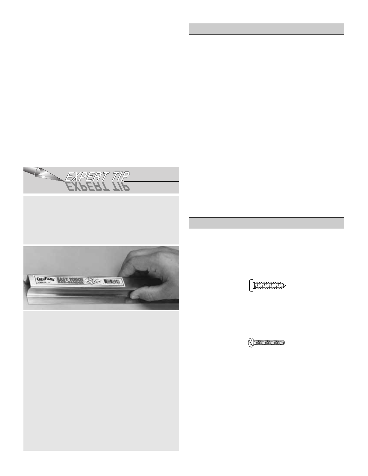
There are two types of screws used in this kit:
Sheet metal screws are designated by a number and a length.
For example #6 x 3/4" [1.91mm]
Machine screws are designated by a number, threads per
inch, and a length.
For example 4-40 x 3/4" [1.91mm]
•
When you see the term “test fit” in the instructions, it
means you should first position the part on the assembly
without using any glue, then slightly modify or “custom
fit” the part as necessary for the best fit. Do not glue until
told to do so.
•
When you see the term “fit” in the instructions, it means
you should first position the part on the assembly without
using any glue, then modify or “custom fit” the part as
necessary for the best fit. Glue when you are satisfied
with the fit. (Continued on page 8)
Important Building Notes
Optional Supplies and Tools
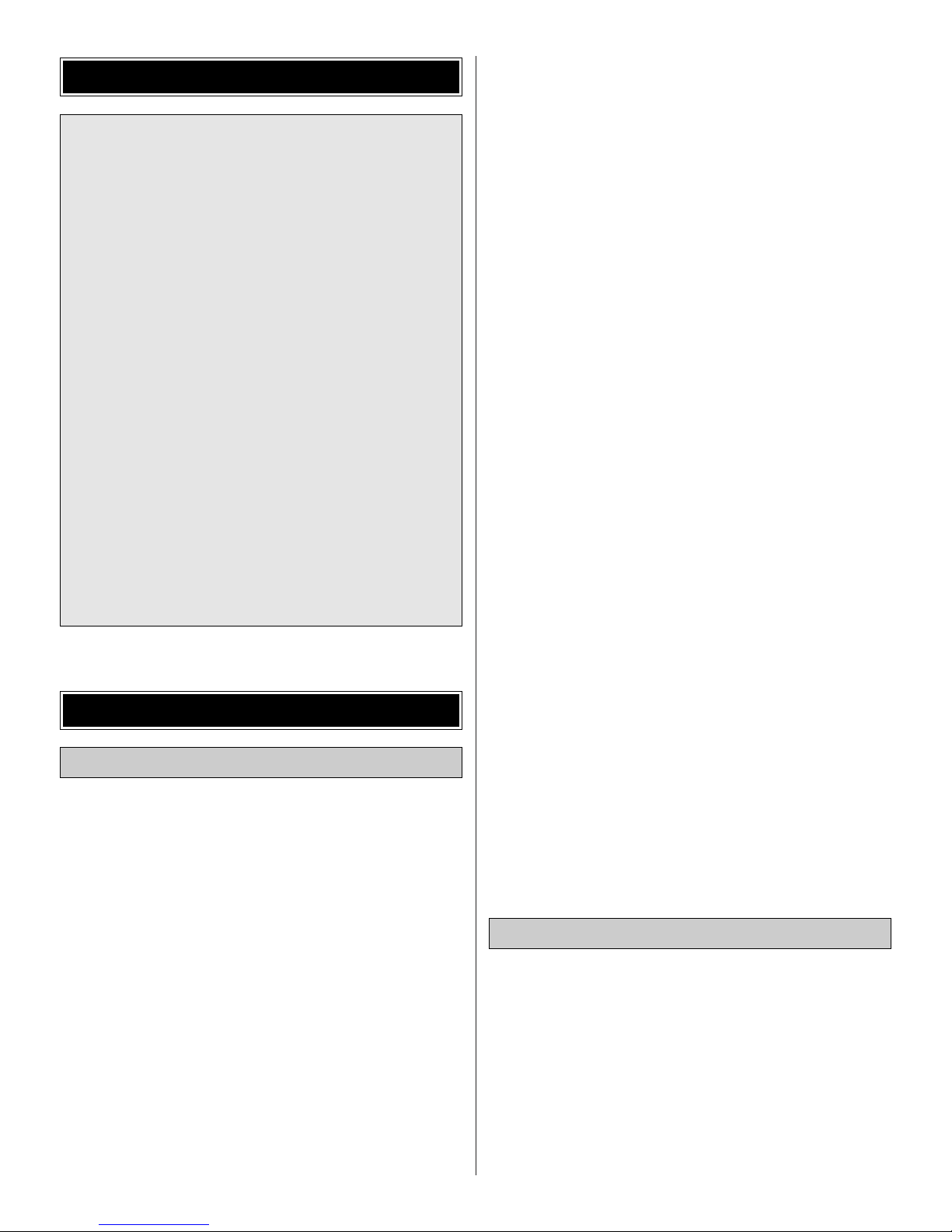
Great Planes Easy-Touch Bar Sanders are made from
lightweight extruded aluminum and can be found at most
hobby shops. They are available in five sizes.
5-1/2” (GPMR6169) for those tight, hard-to-reach spots;
11” (GPMR6170) for most general purpose sanding;
22” (GPMR6172), 33” (GPMR6174) and 44” (GPMR6176)
for long surfaces such as wing leading edges. The Easy-
Touch Adhesive-Backed Sandpaper comes in 2” x 12’
rolls of 80-grit (GPMR6180), 150-grit (GPMR6183) and
220-grit (GPMR6185) and an assortment of 5-1/2” long
strips (GPMR6189) for the short bar sander.The adhesivebacked sandpaper is easy to apply and remove from your
sanding bar when it’s time for replacement.
Custom sanding blocks can be made from balsa or
hardwood blocks and dowels for sanding difficult-toreach spots.
On our workbench, we have three 11” Great Planes
Easy-Touch™Bar Sanders, equipped with #80, #150
and #220-grit sandpaper. This setup is all that is required
for almost any sanding task. We also keep some
#320-grit wet-or-dry sandpaper handy for finish sanding
before covering.
5
6
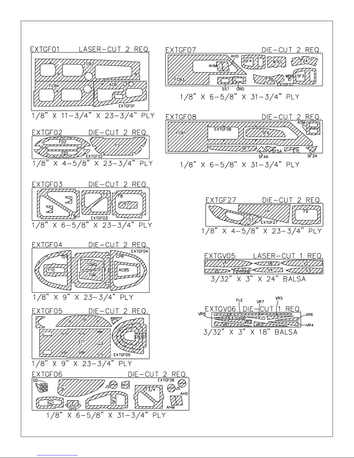
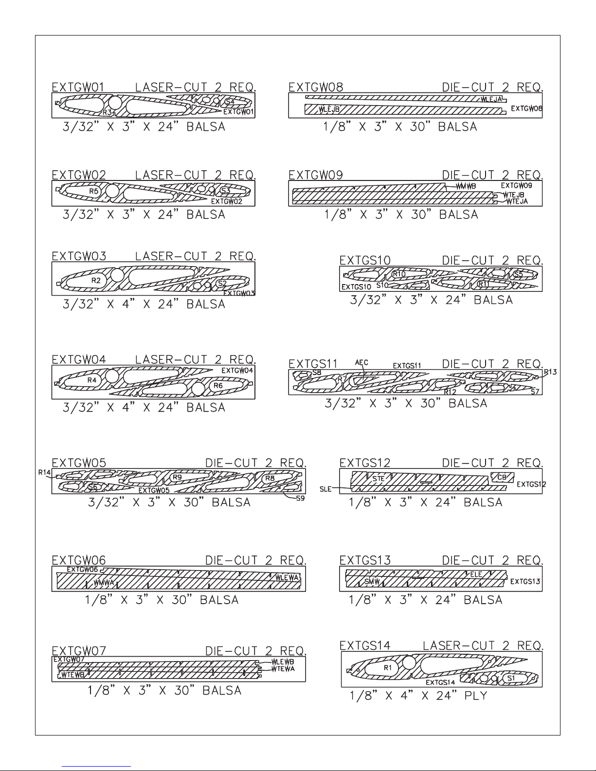
DIE-CUT PATTERNS
7
DIE-CUT PATTERNS
(Continued from page 5)
•
Whenever just “epoxy” is specified you may use
either
30-minute epoxy or6-minute epoxy. When 30-minute
epoxy is specified it is highly recommended that you
use only 30-minute epoxy because you will need the
working time and/or the additional strength.
•
Where you see the term “glue”, it is at your option to
select the thickness of CA with which you are most
comfortable. If the step indicates a particular thickness of
glue, be sure to use the thickness recommended for
strength, penetration, and/or working time.
•
Several times during construction we refer to the “top” or
“bottom” of the model or a part of the model. For example,
during fuse construction we tell you to “glue the top
stringer”. It is understood that the “top” or “bottom” of the
model is as it would be when the airplane is right-side-up
and will be referred to as the “top” even if the model is
being worked on upside-down. For example, the “top”
stringer is always the “top” stringer even when the fuse is
being built upside-down.
Elev = Elevator Fuse = Fuselage
LE = Leading Edge (front) LG = Landing Gear
Ply = Plywood Stab = Stabilizer
TE = Trailing Edge (rear) " = Inches
1. Unroll the plan sheets, then reroll the plan inside-out to
make them lie flat.
2. Sort through the sticks and sheets, grouping them by
size. Masking tape can be used to bundle matching sheets
and sticks. Using a felt tip or ballpoint pen, lightly write the
part name or size on each piece or bundle. Refer to the
parts list and plan for sizes and quantities. Use the die-cut
patterns shown on pages 6 & 7 to identify the die-cut parts
and mark them before removing them from the die sheet.
Save all leftovers. If any of the die-cut parts are difficult to
remove, do not force them! Instead, cut around the parts
with a hobby knife or lightly sand the back of the sheet. After
removing the die-cut parts, use your sanding block to lightly
sand the edges to remove any die-cutting irregularities.
3. As you identify and mark the parts, separate them into
groups, such as fuse (fuselage), wing, fin, stab (stabilizer)
and hardware.
DESIGNER’S NOTE: Before you begin construction, it is
important that we take a moment to cover the issues of
structure and weight. This model is designed to be
EXTREMELY lightweight. As such, it is a superb aerobatic
performer and is also VERY structurally sound. However, if
you are concerned about strength and modify the design,
adding material such as sheeting for the bottom of the
fuselage, you may unintentionally increase the flying weight
of the aircraft without adding sufficient structural integrity to
compensate. While one small change won’t likely hurt the
aircraft, small changes quickly accumulate to the point of
actually increasing the risk to the aircraft. If you trust the
design and add nothing, you will be rewarded with an
exceptional flying, extremely durable, gorgeous aircraft.
Because of the incredible light weight of this design, some of
the structure is fragile during construction. Be sure to take
your time and handle the model with care, being particularly
careful about not picking up sheeted areas by the sheeting
for risk of putting your fingers through the sheet, etc. The
balsa cross trusses in the fuse are likewise fragile and
should not be used to pick up the aircraft; however,
structurally they do their job perfectly: in flight, the cross
trusses would never be subject to such a load. Again, do not
let this fragileness concern you, and we strongly
recommend NOT making changes to the design based
upon this apparent fragileness. When completed and
covered, the aircraft is VERY structurally sound.
Zipper-top food storage bags are handy to store the small
parts as you sort, identify and separate them into
sub-assemblies.
GET READY TO BUILD
1/64" = .4mm
1/32" = .8mm
1/16" = 1.6mm
3/32" = 2.4mm
1/8" = 3.2mm
5/32" = 4mm
3/16" = 4.8mm
1/4" = 6.4mm
3/8" = 9.5mm
1/2" = 12.7mm
5/8" = 15.9mm
3/4" = 19mm
1" = 25.4mm
2" = 50.8mm
3" = 76.2mm
6" = 152.4mm
12" = 304.8mm
15" = 381mm
18" = 457.2mm
21" = 533.4mm
24" = 609.6mm
30" = 762mm
36" = 914.4mm
1" = 25.4mm (conversion factor)
Metric Conversions
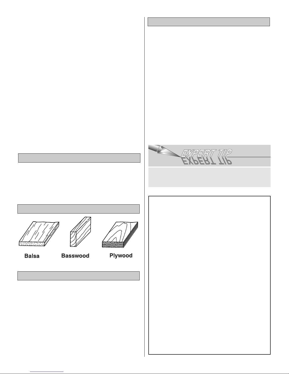
Types of Wood
Common Abbreviations
8
Right now, while the building board is clear, is a great time
to assemble the stab sheeting.
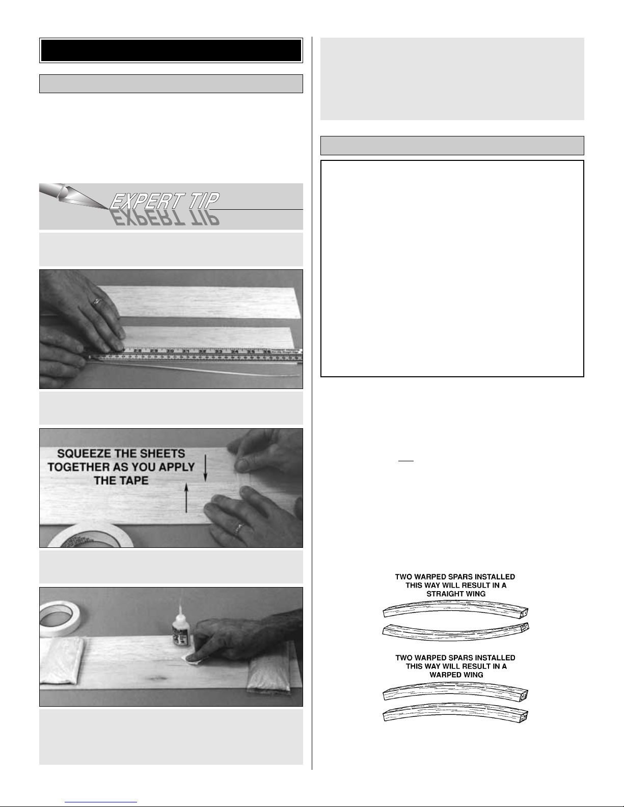
❏ 1. See the Expert Tip that follows, then edge glue four
sets of two 3/32"x4"x24" balsa sheets together, creating four
stab sheets. Set them aside.
You may separate the stab and elevator drawing from the
plan by cutting along the dashed line. Don’t forget to always
cover the plans with Great Planes Plans Protector so the
glue won’t stick to the plan.
❏❏1. Tape the left
stab plan to the building board, and
cover the stab drawing with Great Planes Plans Protector
(so you won’t glue the stab to the plan!)
❏❏2. Before using the 1/8" x 1/4" x 24" basswood spars,
examine them carefully for warps. If the spars are warped
slightly, try to “balance them out” by installing the warped
spars in opposite directions (see sketch).
❏❏3. Position the spar on top of the plan with excess
overhanging both S1 and S8. Pin it in place inboard of S1
and outboard of S8.
The construction of this stab, fin and wing are all
engineered specifically to provide perfectly straight and
true panels with minimum effort on your part. To do so,
the building sequence and pieces are quite different from
what you may be accustomed to. Be sure to read all steps
carefully and pay particular attention to the instructions of
when and where to apply adhesives. DO NOT GLUE until
instructed to do so.
Occasionally outside forces such as humidity and
dramatic temperature changes can result in slight
inaccuracies in the dimensions of printed plans. One of
the many advantages of a fully interlocking stab such as
this one is that exact alignment over a printed plan is not
necessary to ensure a straight stab. If the ribs do not
align perfectly over the plans, don’t worry! As long as the
spar is aligned as shown, the stab will be right.
Build the Stab & Elevators
D. Turn the sheet over and remove the masking tape,
then apply thin CA to the seam the same way you did for
the other side.
E. Sand the sheet flat and smooth with your bar sander
and 150-grit sandpaper.
C. Turn the sheet over and place weights on top of the
sheet to hold it. Apply thin CA sparingly to the seam
between the two sheets, quickly wiping away excess CA
with a paper towel as you proceed.
B. Use masking tape to tightly tape the two sheets
together, joining the trimmed edges.
A. Use a metal straightedge as a guide to trim one edge
of both sheets.
HOW TO JOIN SHEETING
Assemble the Stab Sheeting
BUILD THE TAIL SURFACES
9
❏❏4. Carefully punch out the four die-cut 1/8" balsa stab
webs (SLE, SMW, STE, and ELE), laser-cut 1/8" ply stab
rib S1, die-cut 1/8" ply dowel doubler (DD) and the die-cut
3/32" balsa stab ribs S2 through S8. Sand the edges
slightly to remove any die-cutting irregularities. Be careful
not to alter the shapes or angles of any of the pieces. If this
is your first stab half, align the dowel holes and glue the stab
dowel doubler to the left side of S1 when positioned over the
plans. If this is your second stab half, align and glue the
doubler to the right side of S1.
❏❏5. Select the S1 through S4 ribs, the phenolic stab
tube socket and the 18" aluminum stab tube. Cut the 18"
aluminum stab tube down to 17" and sand the cut end
smooth so it will slide into the socket easily. Carefully slide
the stab tube socket into the tube holes in ribs S1 through
S4. If the socket does not slide into the ribs, DO NOT force
it. Wrap a small piece of 220 grit sand paper around the
aluminum stab tube and gently sand the inside of the rib
holes. Test fit until the stab tube socket fits properly into the
ribs. Set the tube and socket aside.
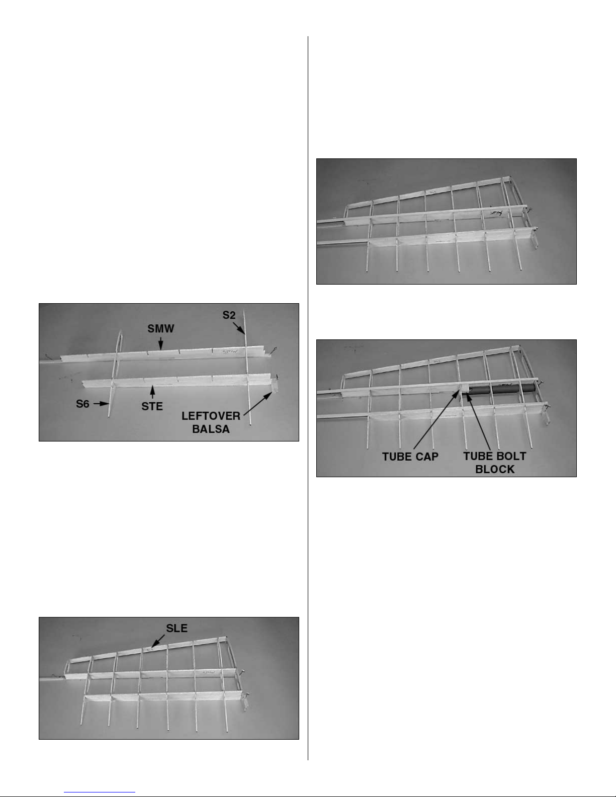
❏❏6. Select the rib S2, main web (SMW), and trailing edge
web (STE). Slide S2 into its slots in the main web and the
TE web. NOTE: Be sure the rib is slid all the way into the
notches, particularly in the TE web which extends beyond
the rib both top and bottom.
❏❏7. Position S6 in its slots to lock the webs in place. Glue
S2 and S6 to the main web and spar. Pin a piece of leftover
balsa flush against the root end of the trailing edge web to
hold the trailing edge web in place.NOTE: If you happen to
crack or break one of the ribs during installation, simply take
it out of the stab, position the pieces together and glue with
thin CA. Allow to dry and reinstall.
❏❏8. Insert ribs S1, S3, S4, S5, S7 and S8 into their locations.
❏❏9. Carefully slide the stab LE web (SLE) onto the front
of the ribs in their notches. Glue all 8 ribs to all 3 webs and
the spar, and the main web to the spar.
❏❏10. Test fit (DO NOT GLUE) the top spar into the ribs,
leaving the excess overhanging both S1 and S8. When you
are confident you can fit the spar in place, remove the spar.
Lay a bead of medium CA along the top of the main web
and the corners of the rib slots, and reinstall the top spar.
❏❏11. Test fit the 1/8" x 1/4" x 24"
balsa
top aft stab spar
into the ribs as you did the main spar. Glue it to the ribs and
trailing edge web.
❏❏12. Align the die-cut 1/8" ply tube cap (SHS) against
the outboard edge of R4 and the main web, centered
vertically on R4. Glue it to the main web and R4. Note: This
piece is identical to the stab horn support.
❏❏13. Carefully slide the stab tube socket through ribs S1,
S2 and S3 and tight against the tube cap on the aft side of
S4. (When building your second stab half, put the uncut end
into the stab half, and trim off the excess in step 14.
Remember to keep the leftover piece for in the fuselage.)
❏❏14. Glue the stab tube socket to the ribs and web with
medium CA. Trim the inboard end of the stab tube socket
1/8" inboard of S1. NOTE: Do NOT use thin CA for this step,
as you may saturate the stab tube socket and get CA into
the inside of the stab tube socket, making fitting the
aluminum stab tube impossible.
❏❏15. Position the 3/8" x 3/4" x 3/4" basswood tube bolt
block against the inboard edge of R4 and the main web.
Glue it in place with medium CA. Note: It may be necessary
to sand the tube bolt block slightly to make it flush with the
top of the ribs and spar.
10
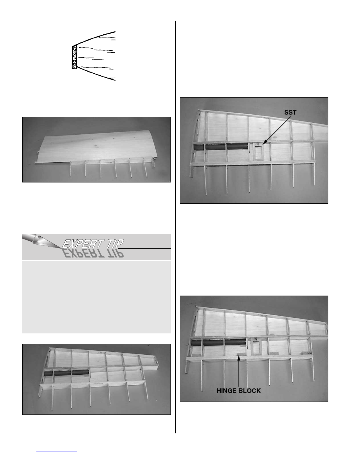
❏❏16. Use a sanding block to shape the LE web so it aligns
with the tops of the ribs and the shape of the airfoil as shown
in the sketch. Be careful not to gouge the ribs or LE web.
❏❏17. Coat the ribs, spar, LE web, aft spar and spar/TE
web joint liberally with medium CA. Carefully position one of
the stab sheets you previously built flush against the TE
web and overhanging S1, S8 and the LE web, being sure
the TE web and spar are both pressed down tight against
the plan. Weight it in place and allow the CA to cure.
❏❏18. Because you have sheeted the top of the stab, you
will need to pull the stab, pins and all, from your work
surface, then unpin the spars from the plan. Trim and sand
the sheeting from the top side of the stab behind the main
web and outboard of S7. Trim and sand the sheeting, spars
and stab tube socket flush with the LE web, ribs S1 and S8.
Hint: Now is a great time to make sure the top sheeting is
firmly glued to all ribs, spars and webs. Touch up with
medium CA as necessary.
❏❏19. Fit and glue the die-cut 1/8" ply elevator servo tray
(SST) in the slots in the webs.
❏❏20. Fit and glue the bottom aft stab spar into the ribs
and against the TE web. Cut the aft stab spar flush with S7
and S1.
❏❏21. From a 3/8" x 5/8" x 24" balsa stick, cut twelve 3/8"
x 5/8" x 1-1/4" hinge blocks. Position and glue the 8 hinge
blocks within this stab half, against the webs and ribs as
shown on the plan.
You can coat the stab parts with CA, then lightly spray the
underside of the sheeting with CA Accelerator, then roll
the sheeting carefully from the trailing edge web, over the
ribs and over the LE. This guarantees an immediate set
with no need to weight the sheeting, and with no chance
of movement of the sheeting.
CAUTION:This technique is “not for the faint of heart” and
requires a steady, confident hand, as the accelerator
WILL cure the CA immediately and any errors made in
placement will be VERY difficult to fix.
11
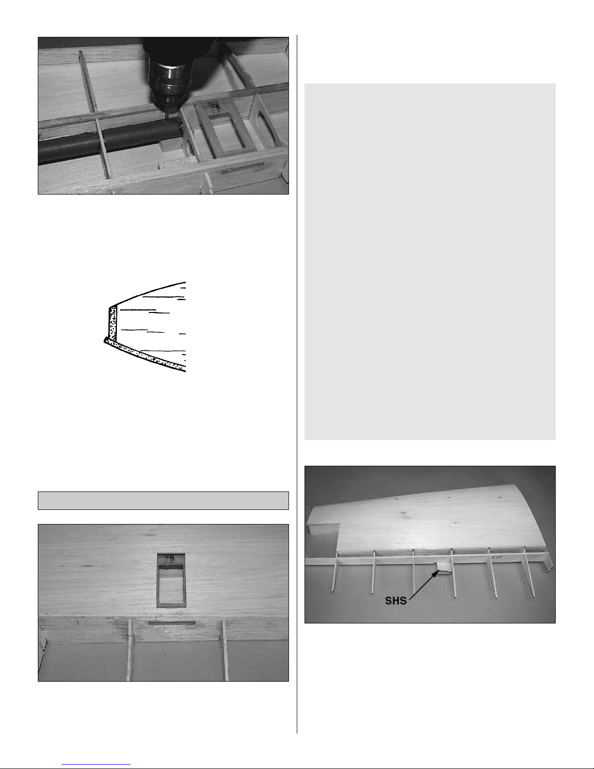
❏❏22. Using a 7/64" drill bit, drill a hole 1/2" inboard of R4
and centered on the tube, all the way through the stab tube
socket, tube support block, and top sheeting. NOTE: The
aluminum stab tube IS NOT drilled in this step. It will be
fitted and drilled to match the fuselage later.
❏❏23. Use a sanding block to shape the LE web so it
aligns with the tops of the ribs and the shape of the airfoil.
❏❏24. Sheet the bottom of the stab as you did the top.Trim
the sheeting from the counterbalancer area (behind the
main spar and outboard of S7) and inboard of S1 and
outboard of S8 as you did for the top.
❏❏1. Using the plan and the location of the trailing edge
of the elevator servo tray as references, cut an opening in
the bottom sheeting for your servo. Note: Be careful not to
split the sheeting.
❏❏2. Turn the stab right-side-up. Slide the elevator LE web
(ELE) over the ribs in their notches until the top of the web
is flush with the top of each rib. Glue in place with thin CA.
❏❏3. Fit and glue the die-cut 1/8" ply elevator control
horn support (SHS) in the slots in the ELE web and S4.
(See note above BEFORE completing this step.)
❏❏4. Place a piece of leftover 1/16" balsa flush against S7
and over the position of CB. (This piece acts as a spacer
and ensures a straight counterbalance.) Carefully position
the die-cut 3/32" balsa rib S9 in its slot in the elevator LE
web 1/16" away from S7. Glue it in the web with thin CA.
NOTE for Non-Computer Radio and Entry Level
Computer Radio Users:
If you are using an entry level computerized radio, you will
need to find out now whether or not your radio has the
ability to properly support twin elevator servos (some
entry level computer radios can’t mix two elevator servos
properly because the trims do not function correctly.) If
your radio cannot properly support twin elevator servos,
you will need to choose one of the options below.
(Futaba’s 6XA, 8U, and 9Z all handle twin elevator servos
without difficulty.)
If you are not using a computer radio, you need to make
an important decision now. A computerized radio user
would simply mix the 2 channels together and switch the
direction of one of the servos to make this ideal pushrod
configuration work properly; however, if you are not using
a computerized radio you will need to:
a) purchase a servo-reversing Y-harness which reverses
one servo’s direction; or
b) purchase a standard Y-harness and a servo reversing
extension; or
c) purchase a standard Y-harness and a reversed servo
for one of the elevator halves; or
d) purchase a standard Y-harness and move the control
horn mount on the right stab half from the outboard edge of
S4 to the inboard edge of S5, and mount each servo’s arm
to the upright aircraft’s right side. (Computerized radio
users have both toward the inboard edge of the stab.)
Finish the Elevators
12
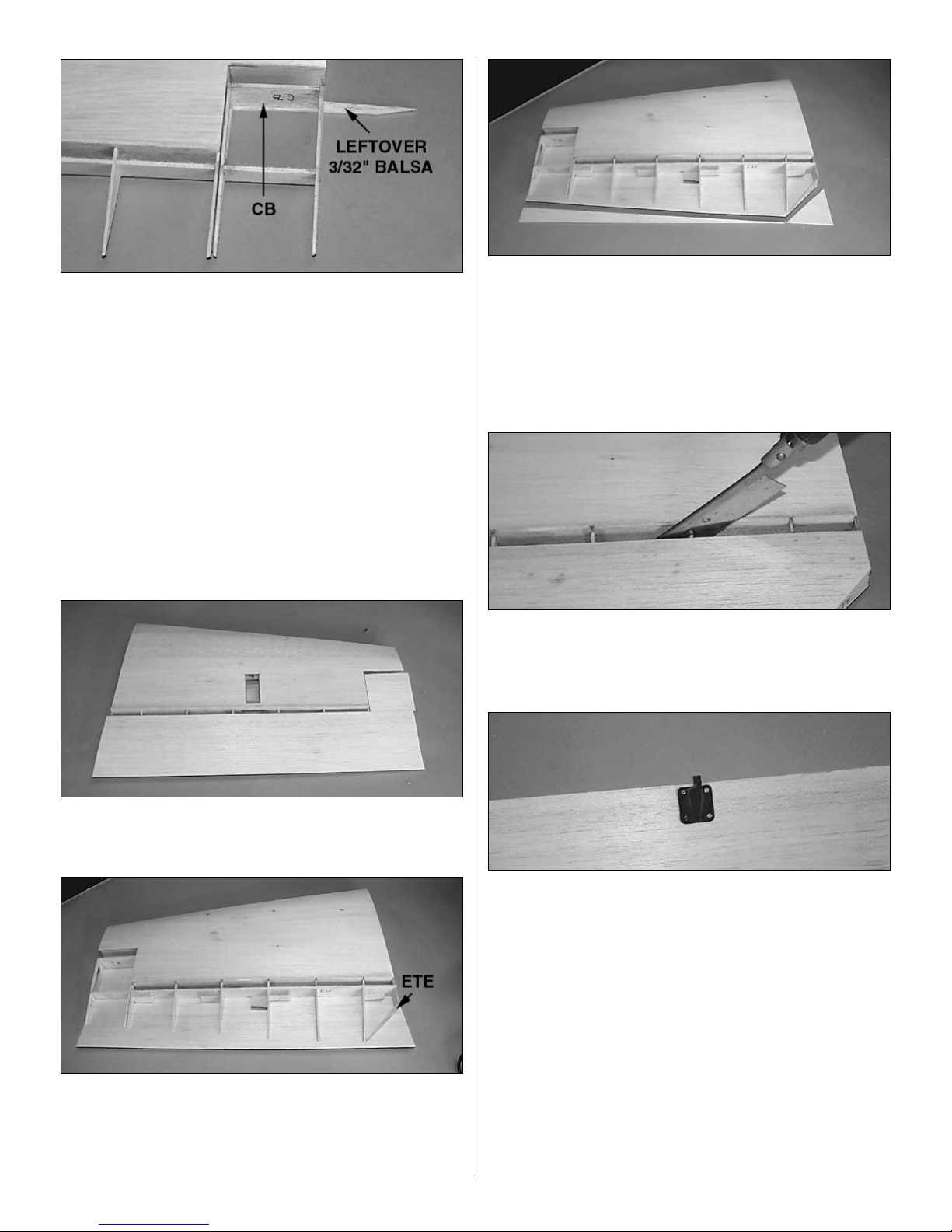
❏❏5. Place the S10 rib onto the elevator LE web. Place the
die-cut 1/8" balsa counterbalance web (CB) into the
notches in the front of S9 and S10. Tack glue CB to the S9
and S10 ribs. Glue S10 to CB and elevator LE web. Note:
Be careful not to glue anything to the spacer or to the stab.
❏❏6. From a 3/32" x 4" x 24" sheet, cut a 3" long
counterbalance sheet and the 21" long elevator sheet.
Trim the counterbalance piece to 3/32" x 3" x 3" and
set aside.
❏❏7. Place a bead of medium CA along the portion of
each rib aft of the elevator LE web and the elevator LE web.
Being careful not to press hard enough to rotate the
counterbalance or twist the ribs, hold the sheeting in place
until the CA dries.
❏❏8. With the grain running the same direction as the
main elevator sheeting, position and glue the
counterbalance sheeting in place.
❏❏9. Flip the stab/elevator right-side-up. Position and glue
the remaining 4 hinge blocks in place in the elevator.
Position and glue the 1/8" die-cut ply elevator trailing edge
rib (ETE) in place on the bottom elevator sheeting and into
the notch in S1.
❏❏10. Measure 5/16" aft of the TE of S2 and S10, and draw
a line between the 2 points. Cut the sheeting along this line
and flush with S1, S10 and the elevator trailing edge. Sand
the sheet flush with S1, S10 and the elevator trailing edge.
Sand the TE of the sheeting to the contour of the ribs.
❏❏11. Sheet the top of the elevator and counterbalance as
you did the bottom. Trim and sand the sheeting.
❏❏12. Using a razor saw, cut the elevator from the stab by
cutting ribs S1 through S7 between the stab TE web and the
elevator LE web. Be VERY careful not to cut into S9. Sand
the leading edges.
❏❏13. Position the elevator control horn (not included) on
the elevator as shown on the plan. Drill four 1/16" holes,
then mount the control horn to the elevator with four #2 x
3/8" sheet metal screws.
❏❏14. Draw a line around the control horn, remove it, and
poke approximately a dozen pin holes in the top sheeting
within the rectangle you drew, then apply a generous
amount of thin CA. Allow the CA to cure, hardening the
balsa, then sand the sheeting smooth. NOTE: Use enough
CA to have some enter the screw holes; however, do not
use so much that you fill the holes with CA.
❏❏15. Select the 3/8" x 1-1/4" x 24" elevator leading
edge. Glue it, centered on the leading edge of the elevator
and flush with S9.
13
❏❏16. Select the 9/16" x 1-3/8" x 2-3/4" balsa
counterbalance leading edge and glue it centered on the
leading edge of the counterbalance portion of the elevator
with excess overhanging both ends. Sand both leading
edges flush with the sheeting, S1 and S9, S10.
❏❏17. Bevel the elevator LE and round the counterbalance’s
leading edge.
❏❏1. Select a 1/4" x 1" x 24" balsa stick, for the stab
leading edge. Leaving 1/4" of LE stock extending beyond
the inboard edge of S1 and keeping the LE centered
vertically on the LE web, glue the LE to the front of the wing
with medium CA.
❏❏2. Trim the LE flush with S1 and S10. Sand the LE to
blend with the stab, forming a smooth airfoil shape.
❏❏3. Sand the trailing edge web flush with the sheeting
top and bottom.
❏❏4. Use HobbyLite
™
balsa colored filler to fill in the gaps
in the trailing edge web at the ribs as well as any other
minor blemishes in your stab or elevator. Allow the filler to
dry completely before sanding it to shape.
❏❏5. Using leftover 3/32" balsa, cap the outboard ends of
both elevator halves and stab halves. Trim and sand the
caps smooth.
❏❏6. Using giant scale hinges (not included — we used
Robart Giant Scale Pin Hinges on the prototypes), hinge
the elevator to the stab.
❏ 7. If this is the first time through, go back to the start of
BUILD THE STAB/ELEVATORS and build the other stab
half. If it’s your second time through, get a good night’s
sleep! You’ve got a great start! At this rate, your Extra will be
framed up in no time.
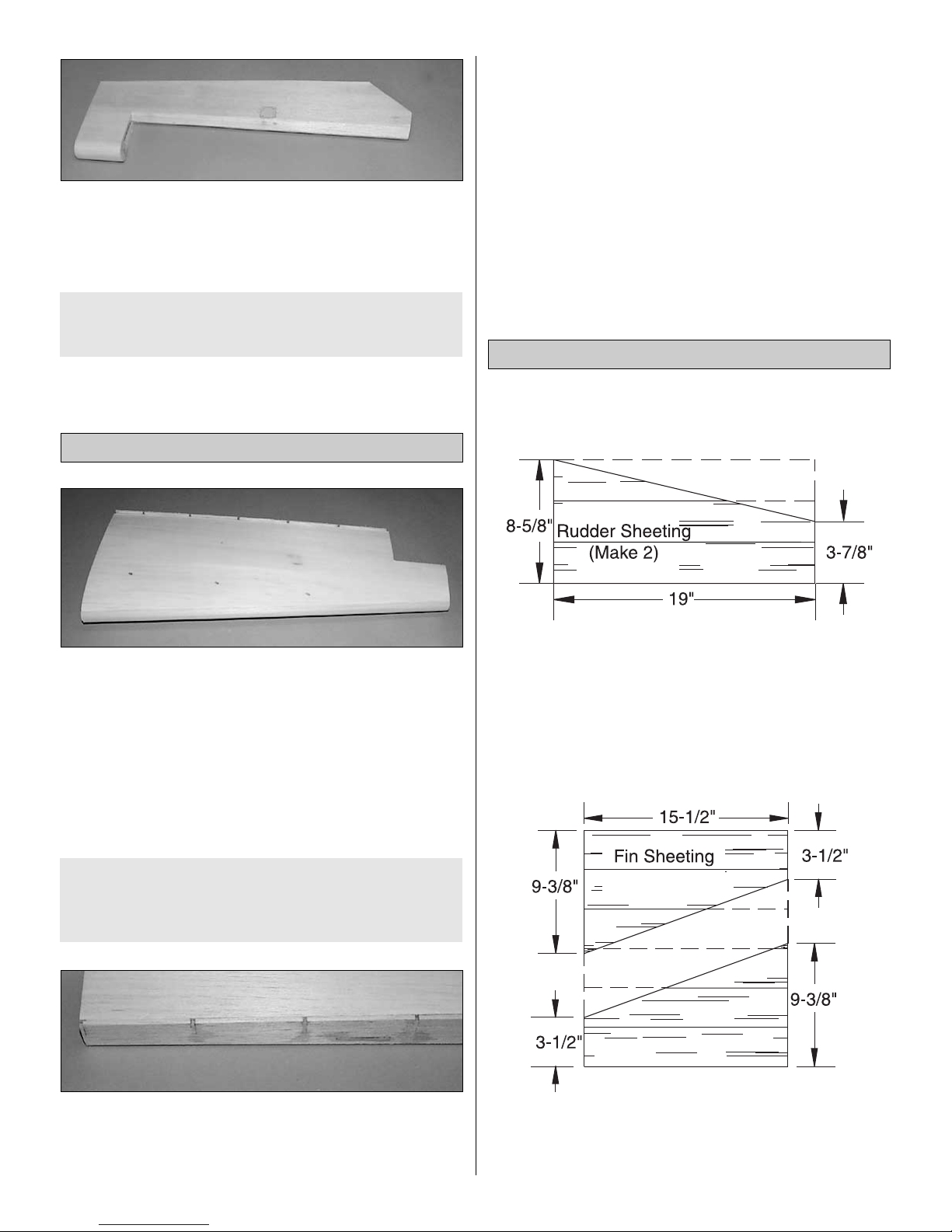
Build the Fin and Rudder Sheeting
❏ 1. While your work surface is clear, now is the perfect time
to build your fin and rudder sheeting. Select six 3/32" x 3" x
36" balsa fin and rudder sheets. Cut all 6 sheets into two
pieces, one 19" long and one 15-1/2" long, and set aside the
leftover. Edge glue two sets of three 19" sheets. Cut these
two 19" long sheets into two rudder sheets which are 19" long
and 9" wide at one end and 4-1/2" wide at the other.
❏ 2. Edge glue the six 15-1/2" long sheets together. From
one end, cut one 15-1/2" long stab sheet which is 9-3/8"
long at one end and 3-3/4" long at the other. From the other
square edge, cut the second stab sheet.
Build the Fin & Rudder
If you are going to double bevel your elevators, glue an
additional 1/2" x 1-1/4" x 16" balsa stick (not included) to
the trailing edge of the stab. Bevel this new trailing edge
as you did the elevator leading edge.
Finish the Stab Panels
If you are going to double bevel your elevators, glue an
additional 1/2" x 1-3/8" balsa counterbalance leading
edge to your counterbalance (not included).
14
Build the Fin
❏ 1. Cut the Fin plan from the plan sheet. Cover it with Great
Planes Plan Protector so the glue won’t stick to the plan.
❏ 2. Select the two 3/8" x 1-5/8" x 24" balsa sticks and
carefully choose the straightest of the 2 sticks for the fin
post. Set the second post aside for the rudder LE.
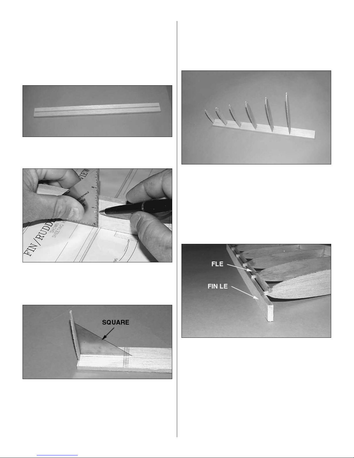
❏ 3. Cut the fin post to 18-7/8" long. Draw a centerline down
the fin post lengthwise to mark where the fin ribs will be
centered.
❏ 4. Carefully position the fin post over the plan. Using a
square, mark the top and bottom edges of each rib on the
fin post. HINT: You may temporarily pin the fin post in place
during this process.
❏ 5. Position the laser-cut 3/32" balsa vertical rib V7 so
that the rib is:
a) positioned between the lines you drew in step 6;
b) centered laterally on the fin post on the centerline you drew;
c) vertical;
d) and with the LE web notch pointing toward the model’s
left as shown in the photo. When you are confident it is
positioned properly, glue with thin CA. NOTE: Remember
that all references such as “laterally” and “model’s left”
indicate the part’s final position on the finished model and
not necessarily its current orientation.
❏ 6. Install the laser-cut vertical ribs V1-V6 as you did V7,
being careful that all tabs are pointing to the model’s left.
❏ 7. Aligning the fin post and ribs over the plan, pin the fin
post to the plan.
❏ 8. Select the 1/4" x 3/4" x 18" balsa fin LE, which will be
temporarily used as a LE jig at this time, and the die-cut
3/32" balsa fin LE web (FLE). Slip the LE jig under the tabs
on ribs V1-V7 so that the tabs are held 3/4" off the work
surface. Slide the LE web into position on all 7 ribs, being
careful that ribs V5 and V6 are properly positioned to the top
and bottom edges of the jig notch respectively. Glue the LE
web in place, being careful not to glue it to the LE jig or to
glue V5 to V6.
❏ 9. Sand the left side of the LE web to match the airfoil of
the ribs as you did on the stab LE web.
15
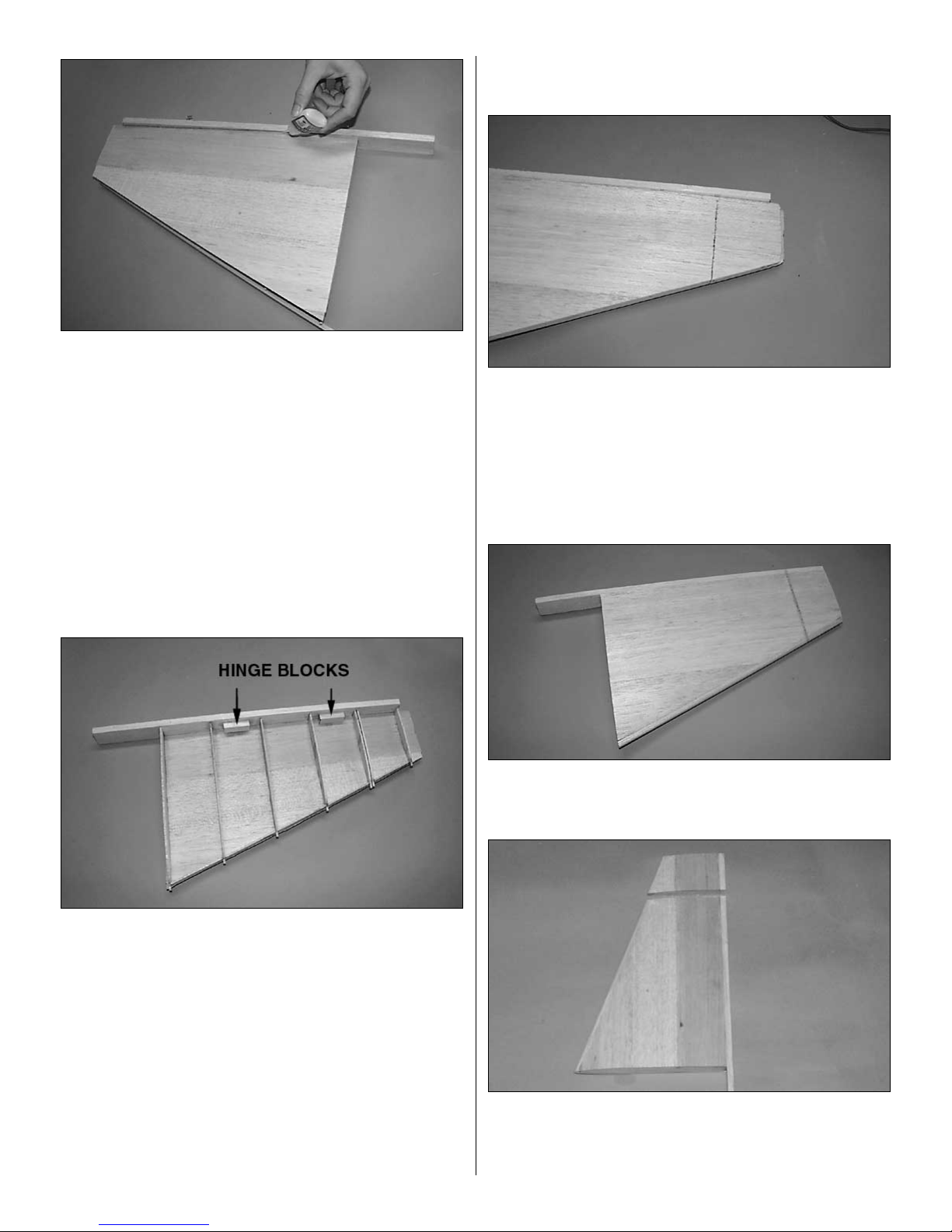
❏ 10. Position the first fin sheet flush against the fin post
and the TE of the ribs, with the lower edge overhanging rib
V1 slightly. Glue the sheet to the fin post with thin CA.
❏ 11. Gently pull the sheeting back from the ribs and apply a
bead of medium CA along each rib and along the LE web.
Roll the sheet back over the ribs and hold in place until the
CA cures.
❏ 12. Gently pull your fin off your work surface, remove the
pins, and turn it over.
❏ 13. Cut the LE web and the sheeting between ribs V5 and
V6, separating the counterbalance’s sheeting from the fin
sheeting. Cut the LE of the sheeting flush with the LE web,
being careful not to cut the tabs off the ribs.
❏ 14. From the 3/8" x 5/8" x 12" balsa stick, cut and glue the two
1-1/2" long hinge blocks in position as shown on the plan.
❏ 15. Reposition the fin flat on your work surface on its left
side with the LE again acting as a LE jig under the tabs.
Sand the LE web flush with the airfoil shape of the ribs.
Sheet the right side as you did the left, being SURE to keep
the tabs pressed firmly against the jig and the fin post sitting
flat on your work surface. Weight the sheeted fin down and
allow the CA to fully cure. NOTE: Using the jig and
weighting the fin at this critical point will ensure that your fin
is as straight as your work surface. Failure to do so may
result in a warped fin, which will negatively affect the great
flying characteristics of this model.
❏ 16. Once the CA has fully cured, trim the rib tabs off with
a razor saw. Sand the sheet and ribs flush with the LE web.
❏ 17. Trim the sheeting between ribs V5 and V6 with a razor
saw. Trim the excess sheeting off the top and bottom of the
fin and sand flush with ribs V1 and V7.
❏ 18. Center the LE laterally on the LE web, and glue it in
place. Trim the excess off the top and bottom of the fin.
Shape the LE to the airfoil shape of the fin, using the cross
section on the plan as a reference.
❏ 19. Shape the fin post to the shape of the fin. Note: Be
careful not to change the shape of the fin by sanding into
the fin sheet.
❏ 20. Cut the LE and TE between ribs V5 and V6, making
the rudder counterbalance. Sand the top of the fin and top
and bottom of the rudder counterbalance flush with ribs V5,
V6 and V7 respectively.
16
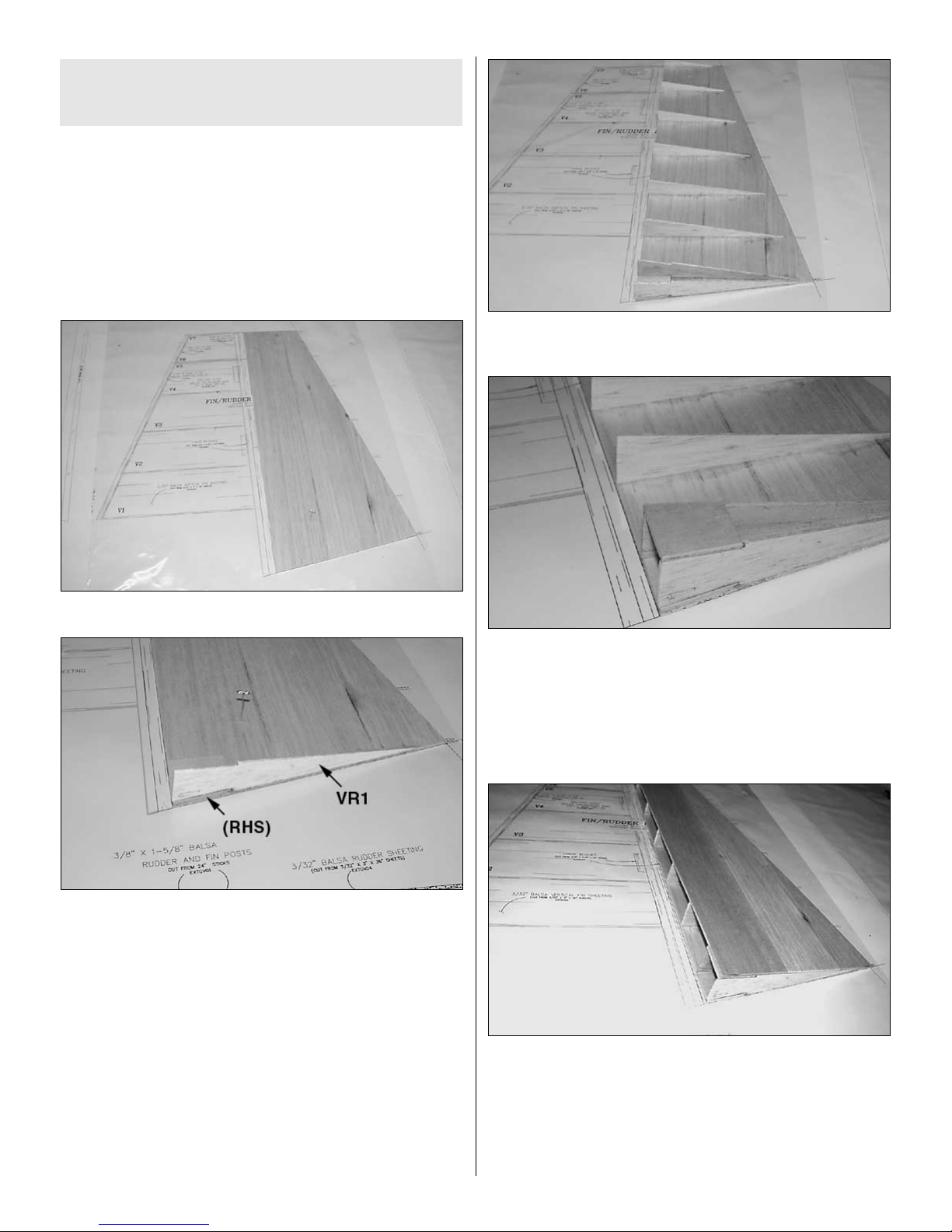
Build the Rudder
❏ 1. Select the two rudder sheets you made earlier.Trim the
first sheet to size, using the 1" dashed lines on the plan as
a reference. Make the second sheet just like the first, and
set the second (left side sheet) aside.
❏ 2. Pin the right side sheet in place over the plan.
❏ 3. Glue the first die-cut 1/8" ply control horn support
(RHS) in position on the sheeting. Hint: Use the mini-plan
in the center of this manual as a handy reference.
❏ 4. Position and glue the die-cut 3/32" balsa rib VR1,
aligned flush with the bottom and leading edges of the
sheeting. Use a square to be sure the rib is vertical.
❏ 5. Position VR2 in place on the sheeting, aligning it with
the top of the control horn support and the leading edge of
the sheeting. Again use a square to be sure the rib is
vertical. Glue VR2 to the sheet and the control horn support
with thin CA. Hint: the shorter dashed lines extending past
the trailing edge of the fin are alignment marks to help you
position ribs VR2-VR8.
❏ 6. Position and glue the die-cut 3/32" balsa ribs VR3
through VR8 to the sheet as you did VR2.
❏ 7. Position and glue the left side control horn support into
its notches in VR1 and VR2.
❏ 8. Unpin the fin from the plan. Use a bar sander to sand
the TE of the sheet until it matches the angle of the ribs. Be
careful not to nick or break the ribs.
❏ 9. Trial fit the left side sheeting to the ribs.When confident
you can position it easily, coat the ribs, right side trailing
edge and left control horn support with medium CA.
Position the left side sheet, aligned with the LE of the ribs
and control horn support, the top and bottom rib and the
trailing edge of the right side sheet. Carefully weight the
rudder down and allow the CA to cure completely.
If you are going to double bevel your elevators, glue a
1/2" x 1-5/8" balsa spacer (not included) onto the leading
edge of the fin post from V1 down to the bottom of the post.
17
 Loading...