

Page 1
Wingspan: 29.5 in [745mm]
Wing Area: 300 sq in [19dm2]
Weight: 20 – 24 oz [567 – 680g]
Wing Loading: 10 – 12 oz/sq ft [31 – 37g/dm2]
Length: 23.5 in [600mm]
Required (not included):
Radio: 4-channel with four micro servos
Motor: ElectriFly™ Rimfi re™ 28-30-950 brushless
ESC: ElectriFly SS-25
Battery: 11.1V 1250mAh LiPo
INSTRUCTION MANUAL
™
Great Planes
®
Model Manufacturing Co. guarantees this kit to be free from def ects in both material and workmanship at the date of purchase.
This warranty does not cover an y component parts damaged by use or modifi cation. In no case shall Great Planes’ liability exceed the
original cost of the purchased kit. Further, Great Planes reserves the right to change or modify this warranty without notice.
In that Great Planes has no control over the fi nal assembly or material used for fi nal assembly, no liability shall be assumed nor accepted
for any damage resulting from the use by the user of the fi nal user-assembled product. By the act of using the user-assembled product,
the user accepts all resulting liability.
If the buyer is not prepared to accept the liability associated with the use of this product, the b uy er is advised to return th is kit
immediately in new and unused condition to the place of purchase.
To make a warranty claim send the defective part or item to Hobby Services at the address below:
Hobby Services
3002 N. Apollo Dr., Suite 1
Champaign, IL 61822 USA
Include a letter stating your name, return shipping address, as much contact information as possible (daytime telephone number, fax
number, e-mail address), a detailed description of the problem and a photocopy of the purchase receipt. Upon receipt of the package
the problem will be evaluated as quickly as possible.
READ THROUGH THIS MANUAL BEFORE
STARTING CONSTRUCTION. IT CONTAINS
IMPORTANT INSTRUCTIONS AND WARNINGS
WARRANTY
CONCERNING THE ASSEMBLY AND USE OF
THIS MODEL.
Entire Contents © Copyright 2007 GPMZ1142 for GPMA1142 V1.0
Champaign, Illinois
(217) 398-8970, Ext 5
airsupport@greatplanes.com
Page 2

TABLE OF CONTENTS
INTRODUCTION
INTRODUCTION ...............................................................2
AMA ..................................................................................2
SAFETY PRECAUTIONS .................................................3
BATTERY CHARGER OPTIONS ......................................3
ADDITIONAL ITEMS REQUIRED ....................................3
Hardware & Accessories ..............................................3
Adhesives & Building Supplies .....................................3
Optional Supplies & Tools ............................................4
IMPORTANT BUILDING NOTES ......................................4
COMMON ABBREVIATIONS ...........................................4
ORDERING REPLACEMENT PARTS ..............................4
KIT INSPECTION ..............................................................5
KIT CONTENTS ................................................................5
PREPARATIONS ...............................................................6
ASSEMBLE THE WING ....................................................6
Install the Ailerons ........................................................6
ASSEMBLE THE FUSE ....................................................7
Mount the Bottom Wing ................................................7
Mount the Stab & Fin ...................................................7
RADIO INSTALLATION ....................................................8
Install the Motor & ESC ................................................8
Install the Linkages ......................................................9
Install the Servos..........................................................9
FINISH THE MODEL .......................................................11
Install the Middle Wing ...............................................11
Install the Top Wing ....................................................12
Install the Sub-Wing & Landing Gear .........................13
Install the Machine Gun & Dummy Engine ................14
Install the Cowl & Propeller ........................................14
Install the Battery .......................................................14
Assemble the Pilot Figure ..........................................15
GET THE MODEL READY TO FL Y .................................15
Check the Control Directions .....................................15
Set the Control Throws ...............................................16
Balance the Model (C.G.) ...........................................16
Balance the Model Laterally .......................................17
PREFLIGHT ....................................................................17
Identify Your Model .....................................................17
Charge the Transmitter Batteries ................................17
Balance the Propellers ...............................................17
Proper Care of Your Motor ..........................................17
Ground Check ............................................................17
Range Check .............................................................17
MOTOR & BATTERY SAFETY PRECAUTIONS ............17
AMA SAFETY CODE (excerpts) ....................................18
CHECK LIST ...................................................................18
FLYING ............................................................................19
Takeoff ........................................................................19
Flight ..........................................................................19
Landing ......................................................................19
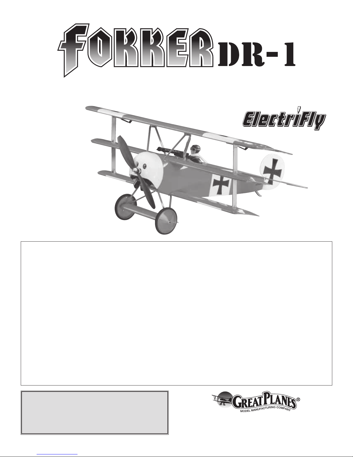
High in the skies over war-torn Europe during WW1 lurked a
man and machine combination that struck terror in the hearts
and minds of the allied forces. The man–Baron Manfred Von
Richtofen; the machine–the Fokker DR-1. Together they
forged the legend of the bloody “Red Baron”!
The Fokker DR-1 is to this day, nearly a century after the
record-setting exploits of the “Red Baron,” one of the most
highly recognized airplanes in the world. Now you can have
this great looking and fl ying model as an electric, without the
mess and fuss of a glow-powered engine.
With today’s LiPo (Lithium-Polymer) batteries and micro
servos, small electrics have become very popular. Now
Great Planes brings you the Fokker DR-1 in a small, easy to
fl y, ARF electric. So if you want to impress your glow-fl ying
buddies with an electric, the Great Planes Fokker DR-1 EP
ARF is just what you need.
For the latest technical updates to the Fokk er DR-1 EP ARF,
visit the Great Planes web site at www.greatplanes.com.
Open the “Airplanes” link and select the Fokker DR-1 EP
ARF. IF there is new technical information or changes to this
model, a “tech notice” bo x will appear in the upper left corner
of the page.
AMA
We urge you to join the AMA (Academy of Model Aeronautics)
and a local R/C club. The AMA is the governing body of model
aviation and membership is required to fl y at all AMA clubs.
Though joining the AMA provides many benefi ts, one of the
primary reasons to join is liability protection. Coverage is not
limited to fl ying at contests or on the club fi eld. It ev en applies
to fl ying at public demonstrations and air shows. Failure to
comply with the Safety Code (excerpts printed in the back of
the manual) may endanger insurance cov erage . Additionally,
training programs and instructors are available at AMA club
sites to help you get started the right way. There are over
2,500 AMA chartered clubs across the countr y. Contact the
AMA at the address or toll-free phone number below.
Academy of Model Aeronautics
5151 East Memorial Drive
Muncie, IN 47302-9252
Tele. (800) 435-9262
Fax (765) 741-0057
Or via the Internet at:
http://www.modelaircraft.org
IMPORTANT!! Two of the most important things you can do
to preserve the radio controlled aircraft hobby are to avoid
fl ying near full-scale aircraft and avoid fl ying near or over
groups of people.
2
Page 3

PROTECT Y OUR MODEL, YOURSELF
& OTHERS....FOLLOW THESE
IMPORTANT SAFETY PRECAUTIONS
1. Y our F okk er DR-1 EP ARF should not be considered a to y,
but rather a sophisticated, working model that functions very
much like a full-size airplane. Because of its performance
capabilities, the Fokker DR-1 EP ARF, if not assembled and
operated correctly, could possibly cause injury to yourself or
spectators and damage to property.
2. Y ou must assemb le the model according to the instructions.
Do not alter or modify the model, as doing so may result in an
unsafe or unfl yable model. In a few cases the instructions may
differ slightly from the photos. In those instances, the written
instructions should be considered as correct.
BATTERY CHARGER OPTIONS
The Great Planes Fokker DR-1 EP ARF is designed f or use with
LiPo (Lithium-Polymer) batteries only. All LiPo batteries require
a charger specifi cally designed for charging LiPo batteries. The
use of a charger not designed for charging LiPo batteries will
result in damage to the batteries and possibly a fi re.
We recommend the use of the Great Planes Triton
Peak Charger (GPMM3153), the ElectriFly DC PolyCharge™
(GPMM3010), or for charging more than one battery at a
time, the ElectriFly PolyCharge4™ (GPMM3015).
™
2 DC
ADDITIONAL ITEMS REQUIRED
3. Take your time to build straight, true and strong.
4. You must use an R/C radio system that is in
fi rst-class condition.
5. You must correctly install all R/C and other components so
that the model operates correctly on the ground and in the air .
6. You must check the operation of the model before every
fl ight to insure that all equipment is operating and that the
model has remained structurally sound. Be sure to check
clevises or other connectors often and replace them if they
show any signs of wear or fatigue.
7. If you are not an experienced pilot or have not fl own
this type of model before, we recommend that you get the
assistance of an experienced pilot in your local R/C club for
your fi rst fl ights. If you’re not a member of a club, your local
hobby shop has information about clubs in your area whose
membership includes experienced pilots.
We, as the kit manuf acturer, provide y ou with a top quality,
thoroughly tested kit and instructions, but ultimately the
quality and fl yability of your fi nished model depends
on how you build it: therefore, we cannot in any way
guarantee the performance of your completed model,
and no representations are expressed or implied as to the
performance or safety of your completed model.
Hardware & Accessories
In addition to the items listed in the “BATTERY CHARGER
OPTIONS” section, the following is the list of hardware and
accessories required to fi nish the Fokker DR-1 EP ARF.
Order numbers are provided in parentheses.
❏ 4-Channel radio with four micro servos with a minimum
17 oz/in each such as the Futaba® S3107 (FUTM0025)
❏ ElectriFly SS-25 25 amp brushless ESC (GPMM1820)
❏ Electr iFly 3.5mm Bullet
connector adapter (GPMM3122)
™
(male) to 2mm Bullet (female)
❏ ElectriFly 1250mAh LiPo 3-cell battery (GPMP0823)
❏ Futaba R114F 4-channel FM receiver
(low band – FUTL0443, high band – FUTL0442)
❏ Futaba “Y-harness” (FUTM4130)
❏ ElectriFly RimFire
motor (GPMG4560)
™
C28-30-950 brushless
❏ 10" x 4.5" Prop (GPMQ6660)
❏ 3mm Prop adapter (GPMQ4959)
Accessories & Building Supplies
In addition to common household tools and hobby tools, this
is the “short list” of the most important items required to build
the Fokker DR-1 EP ARF. Great Planes Pr o™ CA and Epoxy
glue are recommended.
Remember: Take your time and follo w the instructions to
end up with a well-built model that is straight and true.
❏ 1 oz. [28g] Thin Pro CA (GPMR6002)
❏ 1 oz. [28g] Medium Pro CA (GPMR6008)
❏ Hook & Loop material (GPMQ4480)
❏ #1 Hobby knife (HCAR0105)
❏ #11 Blades (5-pack, HCAR0211)
❏ Medium T-pins (100, HCAR5150)
❏ Builder’s Triangle Set (HCAR0480)
❏ K & S #801 Kevlar
®
thread or string (for stab alignment)
❏ Pliers (HCAR0625)
❏ Wire cutter (HCAR0627)
❏ Clear tape
3
Page 4

Optional Supplies & Tools
ORDERING REPLACEMENT PARTS
Here is a list of optional tools mentioned in the manual that
will help you build the Fokker DR-1 EP ARF.
❏ Stick-on segmented lead weights (GPMQ4485)
❏ Top Flite
❏ Top Flite Hot Sock
®
MonoKote® sealing iron (TOPR2100)
™
iron cover (TOPR2175)
❏ Top Flite MonoKote heat gun (TOPR2000)
❏ 2 oz. [57g] Spray CA activator (GPMR6035)
❏ CA applicator tips (HCAR3780)
❏ CA debonder (GPMR6039)
❏ Robart Super Stand II (ROBP1402)
❏ CG Machine
❏ Precision Magnetic Prop Balancer
• When you see the term test fi t in the instructions, it
means that you should fi rst position the part on the assembly
without using any glue, and then slightly modify or custom
fi t the part as necessary for the best fi t.
• This kit contains primarily metric hardware with just a
couple of exceptions.
• Photos and sketches are placed before the step they
refer to. Frequently you can study photos in following steps
to get another view of the same parts.
• The stab and wing incidences and motor thrust angles
have been factory-built into this model. However, some
technically-minded modelers may wish to check these
measurements anyway. To view this information visit the web
site at www.greatplanes.com and click on “Technical Data. ”
Due to manufacturing tolerances which will have little or no
effect on the way your model will fl y, please expect slight
deviations between your model and the published values.
Fuse = Fuselage
Stab = Horizontal Stabilizer
Fin = Vertical Fin
LE = Leading Edge
TE = Trailing Edge
LG = Landing Gear
Ply = Plywood
" = Inches
mm = Millimeters
ESC = Electronic Speed Control
™
(GPMR2400)
™
(TOPQ5700)
IMPORTANT BUILDING NOTES
COMMON ABBREVIATIONS
Replacement parts for the Great Planes Fokker DR-1 EP ARF
are available using the order numbers in the Replacement
Parts List that follows. The fastest, most economical service
can be provided by your hobby dealer or mail-order company.
To locate a hobby dealer, visit the Hobbico
®
web site at
www.hobbico.com. Choose “Where to Buy” at the
bottom of the menu on the left side of the page. Follow the
instructions provided on the page to locate a U.S., Canadian
or International dealer.
Parts may also be ordered directly from Hobby Services by
calling (217) 398-0007, or via facsimile at (217) 398-7721,
but full retail prices and shipping and handling charges will
apply. Illinois and Nevada residents will also be charged
sales tax. If ordering via fax, include a Visa® or MasterCard®
number and expiration date for payment.
Mail parts orders and payments by personal check to:
Hobby Services
3002 N. Apollo Drive, Suite 1
Champaign, IL 61822
Be certain to specify the order number exactly as listed in
the Replacement Parts List. Payment is by credit card or
personal check only; no C.O.D.
If additional assistance is required for any reason contact Product
Support by e-mail at productsupport@greatplanes.com,
or by telephone at (217) 398-8970.
Replacement Parts List
GPMA2985 Top Wing
GPMA2986 Middle Wing
GPMA2987 Lower Wing
GPMA2988 Fuse Kit
GPMA2989 Tail Surfaces
GPMA2990 Cabanes Set
GPMA2991 Interplane Set
GPMA2992 Wheel (2)
GPMA2993 Landing Gear
GPMA2994 Machine Gun Set
GPMA2995 Cowl Set
GPMA2996 Dummy Engine
GPMA2997 Pilot
4
Page 5
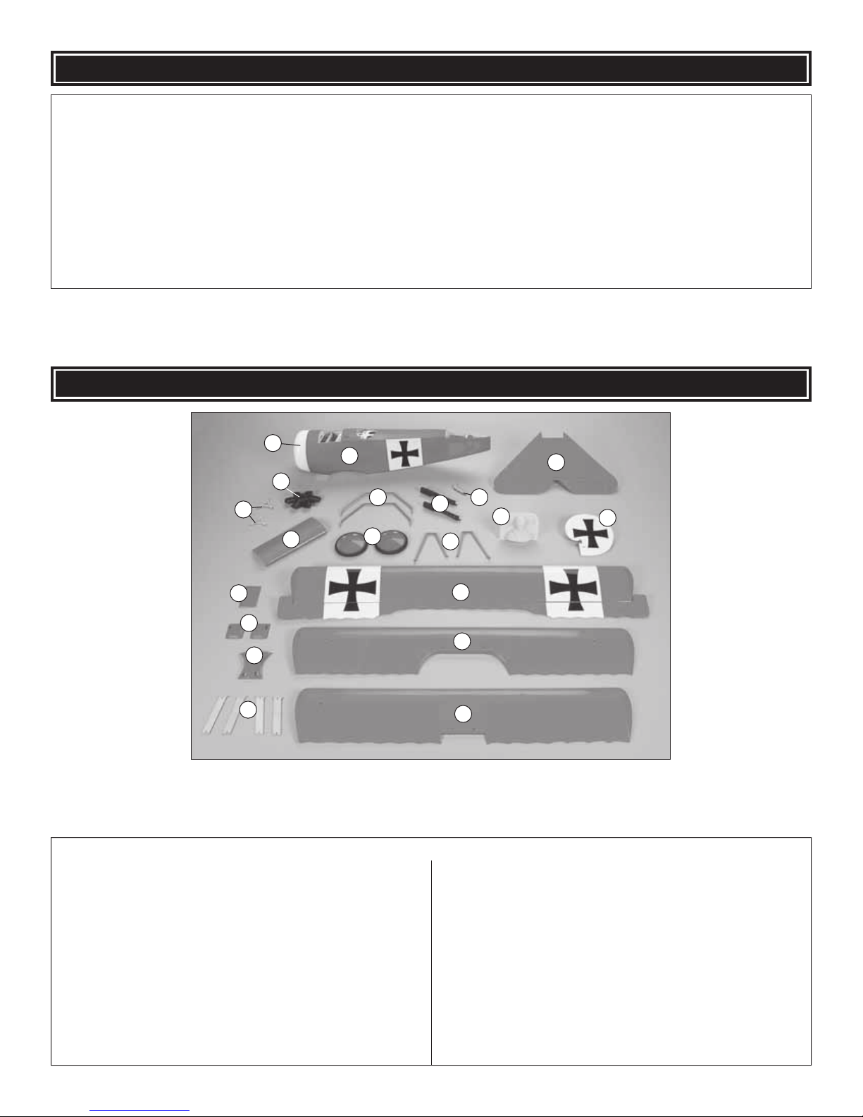
KIT INSPECTION
KIT INSPECTION
KIT CONTENTS
Before starting to build, take an inventory of this kit to make sure it is complete and inspect the parts to make sure they
are of acceptable quality. If any parts are missing or are not of acceptable quality, or if you need assistance with assembly ,
contact Product Support. When reporting defective or missing parts, use the part names exactly as they are written in
the Kit Contents list.
Great Planes Product Support:
3002 N Apollo Drive, Suite 1
Champaign, IL 61822
Telephone: (217) 398-8970, ext. 5
Fax: (217) 398-7721
E-mail: airsupport@greatplanes.com
KIT CONTENTS
14
1
5
4
6
15
16
17
2
7
8
10
9
11
12
18
19
20
3
13
Kit Contents
1 Cowl
2 Fuse
3 Stab with Elevator
4 Motor Mount (2)
5 Dummy Engine
6 Sub-Wing
7 Landing Gear (2)
8 Main Wheels (2)
9 Machine Guns (2)
10 Tail Skid
11 Cabanes (2)
12 Pilot Halves (2)
13 Rudder
14 Battery Cover
15 Aileron Servo Hatch (L&R)
16 ABS Wing Fairing
17 Wing Struts (4)
18 Top Wing Panel with Ailerons
19 Middle Wing Panel
20 Bottom Wing Panel
5
Page 6
PREPARATIONS
ASSEMBLE THE WING
❏ 1. If you have not done so already, carefully remove the
major parts of the kit from the box (wing, fuselage (fuse),
tail parts, etc.) and inspect them for damage. If any parts
are damaged or missing, contact Product Support at the
address or telephone number listed on page 5.
❏ 2. Carefully separate the ailerons from the wing, the
rudder from the fi n and the elevator from the stabilizer (stab).
If necessary, use a covering iron set on medium/high to
carefully tighten the covering. Lay the control surface on
a fl at surface and apply pressure over sheeted areas to
thoroughly bond the cov ering to the wood. Hint: P ok e three
or four pin holes in the covering over the open structure in
the tail surfaces. This will allow the hot air to escape while
tightening the covering.
Install the Ailerons
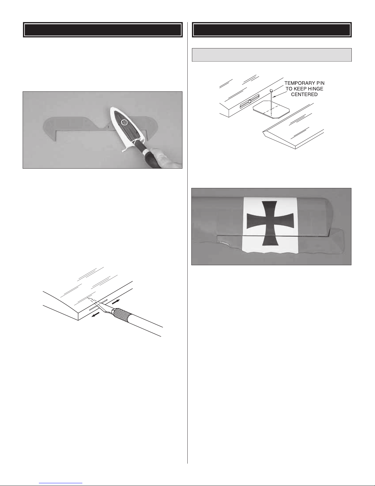
❏ 1. Test fi t the right aileron to the top wing with three 5mm
x 10mm [13/64" x 3/8"] hinges. If the hinges don’t stay
centered, stick a pin through the middle of the hinges to hold
them in position while fi tting the aileron to the wing.
WARNING: DO NOT OVER-SHRINK THE COVERING OR
IT WILL CAUSE THE CONTROL SURFACES TO TWIST.
❏ 3. Check the pre-cut hinge slots of all control surfaces
using a hobby knife with a #11 blade. This will help when
installing the hinges.
❏ 2. Remove any pins you may have inserted into the hinges.
Install the aileron so there is a very small gap between the LE of
the aileron and the wing. The gap should be small – just enough
to see light through or to slip a piece of paper through.
❏ 3. Apply three drops of thin CA to the top and bottom of
each hinge. Do not use CA accelerator. After the CA has
cured, test the hinges by pulling on the ailerons.
❏ 4. Repeat steps 1 to 3 for the left aileron.
6
Page 7

ASSEMBLE THE FUSE
Mount the Bottom Wing
❏ 1. Locate two of the 3mm x 24mm [1/8" x 15/16"] do wel rods
and insert them into the bottom wing as shown, so that only
about 9mm [11/32"] sticks out. Secure them with medium CA.
❏ 2. Mark the center of the TE of the stab. Place the stab
onto the stab saddle.
❏ 3. Stic k a T-pin into the center of the top of the fi rewall. Tie
a small loop in one end of a 900mm [35"] piece of non-elastic
string such as K&S #801 Kevlar thread. Slip the loop in the
string over the T-pin.
❏ 2. Test fi t the bottom wing to the fuse and secure it with
two 3mm x 24mm [1/8" x 15/16"] machine screws and 3mm
[1/8"] washers. The fl at side of the wing is the bottom.
Mount the Stab & Fin
❏ 1. Using a sharp hobby knife, remove the covering from
the stab cut-out at the aft end of the fuse.
❏ 4. Fold a piece of masking tape over the other end of the
string and draw an arrow on it. With the stab centered on the
fuse and the TE of the stab fl ush with the aft end of the fuse,
slide the tape along the string and align the arrow with one tip of
the stab. Swing the string over to the same position at the other
end of the stab. If the arrow doesn’t align with the tip , adjust the
stab and the arrow slightly and check both tips again. Adjust
the stab until the stab tips and the TE are centered.
❏ 5. View the stab from approximately 3m [10'] behind the
plane. Check that the stab is parallel with the wing. If it is
not, lightly sand the stab saddle until the stab is parallel with
the wing.
7
Page 8

❏ 6. Use a fi ne-point felt-tip pen to mark the outline of the
fuse onto the bottom of the stab.
❏ 7. Remo ve the stab from the fuse . Use a sharp #11 hobby
knife or the “Expert Tip” that follows to cut the co vering from
the stab just inside the lines you marked. Use care to cut
only the covering and not the wood. Cutting the wood will
weaken the stab and it may break in fl ight.
HOW TO CUT COVERING FROM BALSA
Use a 25-watt soldering iron to cut the covering from the
stab. The tip of the soldering iron doesn’t hav e to be sharp,
but a fi ne-tip does work best. Allow the iron to heat fully.
Use a metal straightedge to guide the soldering iron at a
rate that will just melt the covering and not burn into the
wood. The hotter the soldering iron, the faster it must tra vel
to melt a fi ne cut. Allow the heat to melt the covering. Do
not apply much pressure or the wood may be damaged.
Peel off the covering.
❏ 10. Install the 10mm x 21mm [3/8" x 13/16"] CA hinge
in the rudder and test fi t it into the rear of the fuse. Adjust
the rudder so that the bottom is even with the bottom of the
fuse. Use a small modeling square to make sure that it is
perpendicular to the stab. Apply 3 drops of thin CA on each
side of the hinge.
❏ 8. Reinstall the stab onto the fuse . Use the string method to
align the stab and glue it in place with thin CA.
❏ 9. Temporarily attach the elevator to the stab with four CA
hinges. IMPORTANT: There is a left and right side to the
elevator. The bottom, right side of the elevator has a small
slot for the elevator control horn. Be sure the elevator half
with the slot is on the bottom, right side of the fuse. Use
T-pins to hold the CA hinges centered in the elevator as you
did when installing the ailerons on the Top wing. Apply 3
drops of thin CA on the top and bottom of each hinge.
❏ 11. Test fi t the tail skid at the rear of the fuse. When
satisfi ed with the fi t, attach the tail skid to the bottom of the
fuse using medium CA.
RADIO INSTALLATION
Install the Motor & ESC
Note: You will need to have your motor battery charged later in
this section. We recommend that you start charging it now so
you do not have to w ait for it to charge later . Mak e sure to closely
follow the charging instructions for charging LiPo batteries. We
also recommend that you remove the bottom wing for this
procedure for better access to the inside of the fuse.
❏ 1. Use epoxy to join the two piece motor mount. Make
sure all openings align.
8
Page 9

❏ 2. Attach the RimFire motor to the back of the plywood
motor mount with three 3mm x 6mm [1/8" x 15/64"] machine
screws. Apply a drop of threadlocker on the threads of the
machine screws. Insert each of three 3mm x 30mm [1/8" x
1-3/16"] machine screws through a 3mm [1/8"] washer, the
outer holes of the motor mount, another 3mm [1/8"] washer, a
17mm [21/32"] tube, and another 3mm [1/8"] washer as shown
in the drawing. Apply a drop of threadlocker on the threads of
each screw and install the motor mount to the fi rewall.
Install the Linkages
❏ 1. Insert a control horn into the r udder slot and elevator
slot as shown. Use a hobby knife to enlarge the hole if
necessary. Once satisfi ed with the fi t, use CA to secure the
control horns in place.
❏ 2. Insert the two 460mm [18"] wire pushrods into the
pushrod exits at the rear of the fuse as shown below.
❏ 3. Cut a 20mm [3/4"] long piece of hook and loop material
(not included). Glue the 20mm [3/4"] soft piece (loop side)
to the back of the ESC. Glue the rough piece (hook side) to
the side of the fuse, next to the battery tray. Insert the ESC
into the battery door and through the cut-out just to the rear
of the fi rewall and secure it in place by joining the hook and
loop material. Route the servo lead into the wing opening
area and the three motor leads out the front of the fi rewall.
❏ 4. Install a 3.5mm [9/64"] Bullet (male) to 2mm [5/64"]
Bullet (female) connector adapter (GPMM3122) on each of
the motor leads. Connect the motor leads to the ESC. Push
the wires up into the fuse to prevent them from contacting the
rotating motor case. Check the motor for proper rotation.
❏ 3. Insert the 90° bends of the 460mm [18"] pushrods into
the outer hole of the control horns and secure them with
the plastic retainers as shown. Place a drop of CA on the
outer surface of the plastic retainers.
Install the Servos
❏ 5. Cut another 20mm [3/4"] long piece of hook and loop
material (not included) and glue the 20mm [3/4"] soft piece
(loop side) to the back of the receiver. Glue the rough piece
(hook side) to the top of the inside of the fuse on the ledge by
the cockpit opening. Insert the receiver and secure it in place
by joining the hook and loop material.
❏ 1. Install the servo mounting hardware and servo arms
on the rudder and elevator servos. Trim off the unused servo
9
Page 10

arms. Insert a screw-lock pushrod connector in the hole of
each servo arm approximately 9mm [11/32"] from the center
of the servo. Secure the scre w-lock pushrod connector to the
servo arm with a nylon retainer.
❏ 2. Position the servos on the servo r ails, aligning them with
the pushrod wires. Drill a 1.6mm [1/16"] hole through each
of the mounting holes in the servo. Install and then remove
a servo mounting screw into each of the holes you drilled.
Apply thin CA into each hole to harden the threads. After the
glue has hardened, plug the ESC, rudder and elev ator servos
into the receiver. Switch on the transmitter and then plug a
battery pack into the ESC. Center the trims on the transmitter
and re-center the servo arms on the servos if necessary so
that the arm is perpendicular to the center line of the servo.
Insert the rudder and elevator pushrod wires into the screwlock pushrod connectors and install the rudder and elevator
servos on the servo rails. Use the hardware included with the
servos to mount the servos to the rails.
❏ 6. Inside the aileron servo bays of the top wing, there is
a string that runs from one bay to the other. Plug the left
aileron servo into a 610mm [24"] Y-harness and tie the string
around the right aileron servo plug. Be sure to secure the left
aileron servo connection with heat-shrink tubing.
❏ 3. Center the elevator control surface and tighten the
set screw in the screw-lock pushrod connector against the
elevator pushrod.
❏ 4. Follo w the same procedure to secure the rudder pushrod.
❏ 5. Clean the cases of both aileron servos with denatured
alcohol. Use CA to glue the aileron servos on the bottom of
the aileron servo hatches so that the servo arm is centered
in the opening. Cut off all of the unused servo arms as you
did in Step 1. If y ou pref er , wrap electrical tape or heat-shrink
tubing around the servos before gluing them to the servo
hatch. This will allow the servos to be removed easily.
TIP: After tying the string to the right aileron servo plug,
use tape to keep the string and plug headed in the same
direction. This accomplishes two things; it keeps the plug
from doubling back over itself and keeps the string securely
fastened to the plug.
❏ 7. Carefully pull the other end of the string until the Y-harness
is near the small opening near the center of the top wing.
Note: Standard size servo connectors have to be worked
through the wing slowly and carefully so as not to damage
the structure of the wing. Be patient. This can be a rather
long step.
❏ 8. Carefully use a bent paper clip or some type of grasping
device to carefully pull out the connector for the receiver.
Leave the right aileron servo connector tied to the string.
❏ 9. Continue pulling the string until the right aileron connector
enters the right aileron bay. Disconnect the string and plug in the
right aileron servo. Secure the connection with heat-shrink tubing.
10
Page 11

❏ 10. Secure each aileron servo hatch to the wing with four
2mm x 6mm [5/64" x 15/64"] self-tapping washer head screws.
❏ 14. Run the Y-harness receiver plug from the top wing
through the slot on the top of the fuse and plug it into the
appropriate receiver channel. Re-install the bottom wing.
❏ 11. Test fi t the control hor ns into the small rectangular
holes along the LE of the bottom of each aileron as shown.
When satisfi ed with their fi t, CA them in place as shown.
❏ 12. Install one 35mm [1-3/8"] aileron pushrod in the outer
hole of the aileron servo arm and another in the outer hole of
the aileron control horn. Slide one of the included pieces of
heat-shrink tubing over the pushrods. With the radio system
on and the aileron servo trim lever centered, shrink the heatshrink tubing over the pushrods and apply a couple of drops
of thin CA to the tubing. Note: A hot soldering iron works
great for shrinking the heat-shrink tubing. Place the top wing
aside for the time being.
FINISH THE MODEL
Install the Middle Wing
❏ 1. Locate the two remaining 3mm x 24mm [1/8" x 15/16"]
dowel rods and insert them into the middle wing as shown,
so that only about 9mm [11/32"] sticks out. Secure them with
medium CA.
❏ 13. Make a small hole in the bottom sheeting. Route the
antenna out of the hole and tape it to the bottom of the fuse
with clear tape.
❏ 2. Place the middle wing on the wing saddle as shown
and secure it with two 3mm x 24mm [1/8" x 15/16"] machine
screws and 3mm [1/8"] washers. The fl at side of the wing is
the bottom.
11
Page 12

❏ 3. Locate the ABS wing fairing. Trim the front and back as
needed for a good fi t. Use medium CA to secure it in place
as shown.
Install the Top Wing
❏ 1. Gather the 12 strut mounts together and carefully study
the photo above. The differences are fairly obvious but to
avoid confusion, arrange them as the y are in the photogr aph
and mark the tab of each set according to the photo.
❏ 3. Grab the two strut mounts that you marked “B” and
insert them into the pockets on top of the middle wing as
shown. DO NOT glue them into place at this time.
❏ 4. Locate the two cabanes and install them as shown
using four 2mm x 6mm [5/64" x 15/64"] self-tapping screws
as shown. Remove the screws and apply a couple of drops
of thin CA into each hole to harden the threads. Re-install
the cabanes.
❏ 2. Grab the two strut mounts that you marked “A” and
insert them into the pockets on the top wing as shown. They
are designed to fi t only one way. If you observe a large gap
between the wing and strut mount, remove it and try it the
other way. DO NOT glue them into place at this time.
❏ 5. Put the top wing in place atop the cabanes and secure
it with four 2mm x 6mm [5/64" x 15/64"] self-tapping screws.
Remove the screws and apply a couple of drops of thin CA
into each hole to harden the threads. Re-install the top wing.
12
Page 13

❏ 6. Study the above dr awing carefully. It sho ws the direction
and placement of the remaining 8 strut mounts and the four
struts. Be sure to insert and remove a 2mm x 6mm [5/64" x
15/64"] self-tapping screw through each one and apply thin
CA into each hole to harden the threads.
❏ 7. Use 2mm x 6mm [5/64" x 15/64"] self-tapping screws to
secure the struts as shown.
Install the Sub-Wing & Landing Gear
❏ 2. Secure the sub-wing to the landing gear with two 2mm x
6mm [5/64" x 15/64"] self-tapping screws as shown. Remo ve
the screws and harden the holes with thin CA. Then, reinstall
the screws.
❏ 3. Attach the landing gear to the bottom of the fuse with
four 2mm x 7mm [5/64" x 9/32"] self-tapping washer head
screws. Remove the screws and harden the holes with thin
CA. Then, reinstall the screws.
❏ 1. Carefully thread the axle through the sub-wing and
attach the rear landing gear strut followed by the front landing
gear strut as shown. The rear strut is identifi ed by a second
hole near the axle hole.
❏ 4. On each end of the axle, place a 3mm [1/8"] washer
and 3mm [1/8"] nut with threadlocker, followed by another
3mm [1/8"] washer and the wheel. Secure the wheel in place
with a 3mm [1/8"] washer and 3mm [1/8"] nut. Apply a drop
of threadlocker to the nut.
13
Page 14

Install the Machine Gun & Dummy Engine
❏ 1. Remove a 13mm x 13mm [1/2" x 1/2"] square of
covering from the top of the fuse in front of the cockpit and
use CA to attach the machine gun mount. Glue the machine
guns in place as shown.
❏ 2. Slide the prop shaft and collet onto the motor shaft. The
collet has a tapered hole through it.
❏ 2. Use Medium CA to glue the dummy engine in place on
the cowl as shown.
Install the Cowl & Propeller
❏ 3. Install a 10" x 4.5" propeller . Install the prop washer and
prop nut and tighten the nut securely.
Install the Battery
❏ 1. Cut a 20mm [3/4"] long piece of hook and loop material
(not included). Glue the rough piece (hook side) to the
battery tray . Glue the 20mm [3/4"] soft piece (loop side) to the
back of the battery pack. Insert the batter y into the battery
compartment and secure it in place by joining the hook and
loop material.
❏ 1. The cowl is held on with three small but powerful
magnets. Put the cowl in place so that the motor shaft is
centered in the opening as shown.
❏ 2. Put the battery cover in place. Note that the lip slides
into the fuse and the aft end is held on with two magnets.
14
Page 15

❏ 3. Use clear tape to secure the aileron wire to the cabanes
as shown and hide the wire with the included segment of red
covering material.
❏ 4. Paint to suit your taste.
Assemble the Pilot Figure
❏ 1. Carefully trim the perimeter of the parts using a shar p
hobby knife.
❏ 5. A small piece of fabric has been provided as “scarf”
material for the pilot. After the paint has dried, tie it in place as
shown for a nice scale touch.
❏ 6. The pilot can be attached to the f ormer at the back of the
cockpit using medium CA. Bef ore gluing, scrape the paint from
the pilot where it will attach to the former.
GET THE MODEL READY TO FLY
Check the Control Directions
Warning: Once the motor battery is connected to the
ESC, stay clear of the propeller.
❏ 1. Switch on the transmitter and connect the motor battery
to the ESC. Move the throttle stick down to the off position.
Switch on the ESC and center the trims.
4-CHANNEL RADIO SETUP
(STANDARD MODE 2)
❏ 2. Sand each half using 150- or 220-grit sandpaper and a
Great Planes Easy-Touch™ bar sander.
❏ 3. Carefully join the halves with thick CA and lightly sand
the seam.
4-CHANNEL
TRANSMITTER
ELEVATOR MOVES UP
4-CHANNEL
RIGHT AILERON MOVES UP
LEFT AILERON MOVES DOWN
TRANSMITTER
RUDDER MOVES RIGHT
4-CHANNEL
TRANSMITTER
4-CHANNEL
TRANSMITTER
FULL THROTTLE
❏ 2. Make certain that the control surfaces respond in
the correct direction as shown in the diagram. If any of
the controls respond in the wrong direction, use the servo
reversing in the transmitter to reverse the servos connected
to those controls. Be certain the control surfaces have
remained centered. Adjust if necessary.
❏ 3. Follow the instructions included with your ESC to arm
the motor. Make sure the propeller is turning in the correct
direction. If not, refer to the ESC instructions to change the
direction of rotation.
15
Page 16

Warning! Once the battery is connected to the ESC, stay
clear of the propeller even if the ESC has not been armed.
Set the Control Throws
Use a Great Planes AccuThrow (or a ruler) to accurately
measure and set the control throw of each control surface
as indicated in the chart that follows. If your radio does not
have dual rates, we recommend setting the throws at the
low rate setting.
Note: The throws are measured at the widest part of the
elevators, rudder and ailerons.
These are the recommended control surface throws:
High Rate Low Rate
ELEVATOR: 3/8" [10mm] up 1/4" [6.4mm] up
3/8" [10mm] down 1/4" [6.4mm] down
RUDDER: 1" [25mm] right 5/8" [16mm] right
1" [25mm] left 5/8" [16mm] left
AILERONS: 3/8" [10mm] up 1/4" [6.4mm] up
3/8" [10mm] down 1/4" [6.4mm] down
IMPORTANT: The Fokker DR-1 EP ARF has been
extensively fl own and tested to arrive at the throws at
which it fl ies best. Flying your model at these throws will
provide you with the greatest chance for successful fi rst
fl ights. If, after you have become accustomed to the way
the Fokker DR-1 EP ARF fl ies, you would like to change
the throws to suit your taste, that is fi ne. How ever , too much
control throw could make the model diffi cult to control, so
remember, “more is not always better.”
Balance the Model (C.G.)
More than any other factor, the C.G. (balance point) can
have the greatest effect on how a model fl ies, and may
determine whether or not your fi rst fl ight will be successful.
If you value this model and wish to enjo y it for man y fl ights,
DO NOT OVERLOOK THIS IMPORTANT PROCEDURE.
A model that is not properly balanced will be unstable and
possibly unfl yable.
This is where your model should balance for the fi rst fl ights.
Later, y ou may wish to experiment by shifting the C .G. up to
3mm [1/8"] forward or 3mm [1/8"] back to change the fl ying
characteristics. Moving the C.G. forward may improve the
smoothness and stability, but the model may then require
more speed for takeoff and make it more diffi cult to slow
for landing. Moving the C.G. aft makes the model more
maneuverable, but could also cause it to become too
diffi cult to control. In any case, start at the recommended
balance point and do not at any time balance the model
outside the specifi ed range.
❏ 2. If you are balancing the Fokker DR-1 EP ARF on the
Great Planes CG Machine, you will fi nd that the angle of
the supports does not allow you to rest the plane forward
enough to reach the balance point. To remedy this, simply
place the front of the CG Machine on a raised surface
(approx. 2" [51mm]). This will allow the plane to be placed
further forward on the balancer.
❏ 3. If the tail drops, the model is “tail heavy” and the motor
battery and/or receiver must be shifted forward or weight m ust
be added to the nose to balance. If the nose drops, the model
is “nose heavy” and the motor battery and/or receiver must
be shifted aft or weight must be added to the tail to balance.
If possible, move the receiver forward or aft to minimize or
eliminate any additional ballast required. If additional weight
is required, use Great Planes “stick-on” lead (GPMQ4485). A
good place to add stick-on nose weight is under the battery
cover (don’t attach weight to the cowl–it is not intended to
support weight). Begin by placing incrementally increasing
amounts of weight on the bottom of the fuse over the fi rewall
until the model balances. Once you have determined the
amount of weight required, it can be permanently attached.
If required, tail weight may be added by cutting open the
bottom of the fuse and gluing it permanently inside.
IMPORT ANT : If y ou found it necessary to add any weight,
recheck the C.G. after the weight has been installed.
At this stage the model should be in ready-to-fl y condition
with all of the systems in place including the motor, landing
gear, motor battery, and the radio system.
❏ 1. Use a felt-tip pen or 3mm-wide [1/8"] tape to accurately
mark the C.G. on the bottom of the top wing on both sides
of the fuse. The C.G. is located 51mm [2"] back from the LE
of the top wing.
16
Page 17

Balance the Model Laterally
Proper Care of Your Motor
❏ 1. With the wing level, lift the model by the prop shaft
and the bottom of the fuse under the TE of the fuse. Do this
several times.
❏ 2. If one wing always drops when you lift the model, it
means that side is heavy. Balance the airplane by adding
weight to the other wing tip. An airplane that has been laterally
balanced will track better in loops and other maneuvers.
PREFLIGHT
Identify Y our Model
No matter if you fl y at an AMA sanctioned R/C club site or
if you fl y somewhere on your own, you should always have
your name, address, telephone number and AMA number
on or inside your model. It is required at all AMA R/C club
fl ying sites and AMA sanctioned fl ying events. Fill out the
identifi cation tag on the back cover page of this manual and
place it on or inside your model.
Charge the Transmitter Batteries
Follow the battery charging instructions that came with your
radio control system to charge the transmitter. Y ou should always
charge your transmitter the night before you go fl ying, and at
other times as recommended by the radio manuf acturer.
Using multiple battery packs to run the motor for successive
fl ights may cause the motor to become excessively hot. We
recommend at least a 10-minute motor cool-down period
between fl ights.
Ground Check
Before the fi rst fl ight, inspect the model closely to make sure
all screws remained tight, the hinges are secure, the prop is
secure and all pushrods and connectors are secure.
Range Check
Ground check the operational range of your r adio before the
fi rst fl ight of the day. With the transmitter antenna collapsed
and the receiver and transmitter on, you should be able to
walk at least 30m [100'] away from the model and still have
control. Have an assistant stand by your model and, while
you work the controls, tell you what the control surfaces are
doing. Repeat this test with the motor running at various
speeds with an assistant holding the model, using hand
signals to show you what is happening. If the control surfaces
do not respond correctly, do not fl y! Find and correct the
problem fi rst. Look for loose servo connections or broken
wires, corroded wires on old servo connectors, poor solder
joints in your battery pack or a defective cell, or a damaged
receiver crystal from a previous crash.
CAUTION: Unless the instructions that came with your
radio system state differently, the initial charge on new
transmitter batteries should be done for 15 hours using
the slow-charger that came with the radio system.
This will “condition” the batteries so that the next charge
may be done using the fast-charger of your choice. If the
initial charge is done with a fast-charger , the batteries may
not reach their full capacity and you may be fl ying with
batteries that are only partially charged.
Balance the Propellers
Carefully balance your propeller and spare propellers before
you fl y. An unbalanced prop can be the single most signifi cant
cause of vibration that can damage your model. Not only
will motor mounting screws and bolts loosen, possibly with
disastrous effect, but vibration may also damage your radio
receiver and servos.
We use a Top Flite Precision Magnetic Prop Balancer
(TOPQ5700) in the workshop and keep a Great Planes
Fingertip Prop Balancer (GPMQ5000) in our fl ight box.
™
MOTOR & BATTERY SAFETY PRECA UTIONS
Failure to follow these safety precautions may result
in severe injury to yourself and others.
Use safety glasses when running the motor.
Do not run the motor in an area of loose gravel or sand; the
propeller may throw such material in your face or eyes.
Keep your f ace and body as w ell as all spectators a wa y from
the plane of rotation of the propeller as you run the motor.
Keep these items away from the prop: loose clothing, shirt
sleeves, ties, scarfs, long hair or loose objects such as
pencils or screwdrivers that may fall out of shirt or jacket
pockets into the prop.
Always remove the LiPo (Lithium-Polymer) battery from the
plane before charging.
Always use a charger designed to charge LiPo batteries for
charging the LiPo fl ight battery.
17
Page 18

Never lea v e the LiPo battery unattended while charging. If the
battery becomes more than just warm, discontinue charging.
AMA SAFETY CODE (excerpts)
Read and abide by the following excerpts from the Academy
of Model Aeronautics Safety Code. For the complete Safety
Code refer to Model A viation magazine, the AMA web site or
the Code that came with your AMA license.
General
1) I will not fl y my model aircraft in sanctioned events , air shows,
or model fl ying demonstrations until it has been proven to be
airworthy by having been pre viously, successfully fl ight tested.
9) Under no circumstances may a pilot or other person
touch a powered model in fl ight; nor should any part of the
model other than the landing gear, intentionally touch
the ground, except while landing.
CHECK LIST
During the last few moments of preparation your mind may
be elsewhere anticipating the excitement of the fi rst fl ight.
Because of this, you may be more likely to overlook certain
checks and procedures that should be performed before the
model is fl own. To help avoid this, a check list is provided to
make sure these important areas are not overlooked. Man y
are covered in the instruction manual, so where appropriate,
refer to the manual for complete instructions. Be sure to
check the items off as they are completed.
2) I will not fl y my model aircraft higher than approximately
400 feet within 3 miles of an airport without notifying the
airport operator. I will giv e right-of-wa y and av oid fl ying in the
proximity of full-scale aircraft. Where necessary, an observer
shall be utilized to supervise fl ying to avoid having models fl y
in the proximity of full-scale aircraft.
3) Where established, I will abide by the safety rules for the
fl ying site I use, and I will not willfully and deliberately fl y my
models in a careless, reckless and/or dangerous manner.
5) I will not fl y my model unless it is identifi ed with my name
and address or AMA number, on or in the model. Note: This
does not apply to models while being fl own indoors.
7) I will not operate models with pyrotechnics (any device
that explodes, burns, or propels a projectile of any kind).
Radio Control
1) I will have completed a successful radio equipment ground
check before the fi rst fl ight of a new or repaired model.
2) I will not fl y my model aircraft in the presence of spectators
until I become a qualifi ed fl ier, unless assisted by an
experienced helper.
3) At all fl ying sites a straight or curved line(s) must be
established in front of which all fl ying takes place with the
other side for spectators. Only personnel involved with fl ying
the aircraft are allowed at or in the front of the fl ight line.
Intentional fl ying behind the fl ight line is prohibited.
❏ 1. Check the C.G. according to the measurements
provided in the manual.
❏ 2. Be certain the motor battery and receiver are securely
mounted in the fuse.
❏ 3. Extend your receiver antenna and make sure it has
a strain relief inside the fuse to keep tension off the
solder joint inside the receiver.
❏ 4. Balance your model laterally as explained in
the instructions.
❏ 5. Make sure all hinges are securely glued in place.
❏ 6. Reinforce holes for wood screws with thin CA where
appropriate (servo mounting screws, cabane mounting
screws, etc.).
❏ 7. Confi rm that all controls operate in the correct direction
and the throws are set up according to the manual.
❏ 8. Make sure that all servo arms are secured to the
servos with the screws included with your radio.
❏ 9. Secure connections between servo wires and
Y-connectors or servo extensions with vinyl tape, heatshrink tubing or special clips suitable for that purpose.
❏ 10. Make sure any servo extension cords you may have
used do not interfere with other systems (servo arms,
pushrods, etc.).
❏ 11. Balance your propeller (and spare propellers).
❏ 12. Tighten the propeller nut.
❏ 13. Place your name, address , AMA number and telephone
number on or inside your model.
❏ 14. If you wish to photograph your model, do so before
your fi rst fl ight.
❏ 15. Range check y our r adio when y ou get to the fl ying fi eld.
4) I will operate my model using only radio control frequencies
currently allowed by the F ederal Comm unications Commission.
5) I will not knowingly operate my model within three
miles of any pre-existing fl ying site except in accordance
with the frequency sharing agreement listed (in the
complete AMA Safety Code).
18
Page 19

FLYING
Flight
The Fokker DR-1 EP ARF is a great-fl ying model that fl ies
smoothly and predictably. The Fokker DR-1 EP ARF does
not, however, possess the self-recovery characteristics of a
primary R/C trainer and should be fl own only by experienced
R/C pilots.
CAUTION (THIS APPLIES TO ALL R/C AIRPLANES): If,
while fl ying, you notice an alarming or unusual sound such
as a low pitched “buzz,” this may indicate control surface
fl utter. Flutter occurs when a control surface (such as an
aileron or elevator) or a fl ying surface (such as a wing or
stab) rapidly vibrates up and down (thus causing the noise).
In extreme cases, if not detected immediately, fl utter can
actually cause the control surface to detach or the fl ying
surface to fail, thus causing loss of control followed by
an impending crash. The best thing to do when fl utter is
detected is to slow the model immediately by reducing
power , then land as soon as saf ely possible . Identify which
surface fl uttered (so the problem may be resolved) by
checking all the servo grommets for deterioration or signs of
vibration. Make certain all pushrod linkages are secure and
free of play. If it fl uttered once, under similar circumstances
it will probably fl utter again unless the problem is fi xed.
Some things which can cause fl utter are; Excessive hinge
gap; Not mounting control horns solidly; Poor fi t of clevis
pin in horn; Side-play of wire pushrods caused by large
bends; Excessive free play in servo gears; Insecure servo
mounting; and one of the most prevalent causes of fl utter;
Flying an over-powered model at excessive speeds.
For reassurance and to keep an eye on other traffi c, it is a
good idea to have an assistant on the fl ight line with you. Tell
him to remind you to throttle back once the plane gets to a
comfortable altitude.Take it easy with the Fokker DR-1 EP
ARF for the fi rst few fl ights, gradually getting acquainted with
it as you gain confi dence.
Adjust the trims to maintain straight and level fl ight. After
fl ying around for a while, and while still at a safe altitude
with plenty of battery power remaining, practice slow fl ight
and execute practice landing approaches by reducing the
throttle to see how the model handles at slower speeds. Add
power to see how she climbs as well. Continue to fl y around,
executing various maneuvers and making mental notes (or
having your assistant write them down) of what trim or C.G.
changes may be required to fi ne tune the model so it fl ies the
way you like. The Fokker DR-1 EP ARF will perform loops,
hammerheads, inverted fl ight and rolls.
When performing rolls you will fi nd that the rolls are more
of a barrel roll. It is recommended you are at a safe altitude
before attempting the roll until you ha ve become f amiliar with
the characteristics of the airplane. Mind your battery power
but use this fi rst fl ight to become familiar with your model
before landing.
Landing
Takeoff
The Fokker DR-1 EP ARF has a tail skid rather than a
conventional tailwheel. This prevents you from having
complete control while trying to taxi. If your fi eld has shor t
grass or is paved, it is recommended that y ou set the airplane
on the runway pointed into the wind to ready the plane for
takeoff. If your fi eld has very thick or tall grass you should
consider hand-launching the airplane.
With the plane pointed into the wind, arm the motor as per
the ESC instructions and slowly advance the throttle. Apply
full power and launch the model into the wind with the wings
level with the horizon. Gradually add “up elevator” when the
plane picks up speed to begin a gentle climb. At this moment
it is likely that you will need to apply more right rudder to
counteract motor torque. Be smooth on the elevator stick,
allowing the model to establish a gentle climb to a safe
altitude before turning into the traffi c pattern.
WWI planes like the Fokker DR-1 are notorious for their
poor ground handling. Your model has been designed for
maximum control without excessively deviating from scale
lines. This said, the airplane is a little trickier on the ground
than other models you may have fl own. We have specifi ed
a high and low rate for the elevator. For normal fl ying you
will fi nd the low rate elevator is more than adequate. You
might want to switch to the high rate f or landing. The airplane
has a tendency to nose over. The additional throw provided
by the high rate elevator will help to minimize nose-overs
when landing. The Fokker DR-1 EP ARF has lots of drag
and slows down quickly when pow er is reduced. Practice the
landing procedure with more altitude fi rst, then try landing!
To initiate a landing approach, lower the throttle while on
the downwind leg. Allow the nose of the model to pitch
downward to gradually bleed off altitude. Continue to lose
altitude, but maintain airspeed by keeping the nose down
as you turn onto the crosswind leg. Make your fi nal turn
toward the runway (into the wind) keeping the nose down to
maintain airspeed and control. Level the attitude when the
model reaches the runway threshold. At this point it is best
to keep up the air speed and the RPM of the motor , fl ying the
plane to the ground. The plane will land best if you fl y it to the
ground landing fi rst on the main wheels and allowing the tail
to naturally settle as the speed decreases. Three point stall
landings will also work but are trickier to do on a consistent
19
Page 20

basis. If you are going to overshoot, smoothly advance the
throttle (always ready on the right rudder to counteract
torque) and climb out to make another attempt. But, if your
battery power is low, do not attempt to go around again. It is
better to land long than risk stalling the plane by fl ying too
slow because the motor battery is low on power.
One fi nal note about fl ying your model: Have a goal or fl ight
plan in mind for every fl ight. This can be learning a new
maneuver(s), improving a maneuver(s) you already know,
or learning how the model behaves in certain conditions
(such as on high or low rates). This is not necessarily to
improve your skills (though it is never a bad idea!), but more
importantly so you do not surprise yourself by impulsively
attempting a maneuver and suddenly fi nding that you’ve run
out of time, altitude or airspeed. Every maneuver should be
deliberate, not impulsive. F or e xample, if y ou’ re going to do a
loop, check y our altitude, mind the wind direction (anticipating
rudder corrections that will be required to maintain heading),
remember to throttle back at the top, and make certain you
are on the desired rates (high/low rates). A fl ight plan greatly
reduces the chances of crashing your model just because of
poor planning and impulsive moves. Remember to think.
Have a ball! But always stay in control and fl y in a
safe manner.
GOOD LUCK AND GREAT FLYING!
OTHER ITEMS AVAILABLE
FROM GREAT PLANES
ElectriFly S.E. 5a WWI Park Flyer EP ARF by Great Planes
On your next trip to the park or fl ying fi eld, give chase to the
Red Baron’s Flying Circus – behind the sticks of ElectriFly’s
all-wood S.E. 5a biplane! This prebuilt version of the famous
RAF fi ghter comes ready to take advantage of the latest
breakthroughs in electric power for long fl ight times and
dogfi ght-winning maneuverability. It assembles quickly from
prebuilt structures of laser-cut, fi lm-covered balsa/ply, and
includes easy-to-install cabanes, struts, and molded details
for vintage warbird looks. Spanning just 34", the S.E. 5a
can stay in one piece for transport in most vehicles. With
its ability to turn sharply and change directions quickly, any
open area can easily become the stage for exciting sport
fl ying and mock combat! GPMA1140
Make a copy of this identifi cation tag and put it on or
inside your model.
ElectriFly Fokker D.VII EP ARF by Great Planes
Like the full-size Fokker D.VII that challenged Allied air
forces in WWI, this prebuilt park fl yer is a spirited performer.
And because the Fokker D.VII park fl yer is an ARF, the highquality, laser-cut wood parts assemble quickly and easily.
Its prebuilt balsa/ply structures are precovered in a highquality fi lm. Lots of impressive details are included, from
the vacuum-formed cowl and realistic machine guns to the
scale-shaped landing gear and scale wheels. The cabanes
and interplane struts come already painted and are shaped
for easy installation and proper alignment. An out-runner
brushless motor gives this model a great power-to-weight
ratio and long fl ight times. The ElectriFly RimFire 28-30-950
motor (GPMG4560) was found to be ideal for the Fokker
D.VII. GPMA1141
 Loading...