

Page 1

mx-16
33116.mx-16 HoTT.3a.en
Programming Manual
Page 2

Contents
General Information
Contents ........................................................................ 2
Warning and information symbols a. their meaning .......3
Environmental protection notes ..................................... 3
Safety Notes .................................................................. 4
Safety notes and handling instructions relating
to Nickel-Metal-Hydride rechargeable batteries ............8
Disposal of exhausted dry and rechargeable batt. ........9
Foreword ......................................................................10
Description of radio control set .................................... 11
Technical specifications ............................................... 13
Recommended battery chargers ................................. 13
Operating notes
Transmitter power supply ........................................ 14
Receiver power supply ...........................................16
Adjusting the stick length ........................................ 17
Opening the transmitter case .................................17
Changing the stick mode ........................................ 18
Description of transmitter ......................................... 20
Front of transmitter .................................................20
Rear of transmitter .................................................. 21
Headphone socket .................................................. 21
Mini-USB socket ..................................................... 21
Data socket ............................................................. 21
DSC socket ............................................................. 22
Card slot / data storage .......................................... 22
Screen and keypad ................................................. 24
Operating the “Data Terminal” .................................25
Short-cuts ............................................................... 25
Hidden Mode
Language selection
Voice messages............................................ 26
Changing the screen language ..................... 27
Firmware update from SD card ......................... 27
Stick calibration..................................................27
Telemetry data displays .......................................... 30
On-screen warnings ............................................... 36
On-screen function fields ........................................ 36
Position indicator of rotary controls CTRL 7 + 8 ..... 37
Input lock ................................................................ 37
Using the transmitter for the first time .................... 38
Downloading a firmware package ..........................40
Firmware-update of the transmitter ........................ 41
Restoring the transmitter firmware ......................... 44
Using the receiver for the first time ......................... 46
Firmware-update of the receiver .............................48
Backing up receiver settings ................................... 52
Installation notes ....................................................... 54
Receiving system power supply ............................. 55
Definition of terms ....................................................... 58
Switch and transmitter control assignment .................. 59
Digital trims .................................................................. 60
Fixed-wing model aircraft ......................................... 62
Receiver socket sequence ...................................... 63
Servo with incorrect direction of rotation ................ 63
Model helicopters ...................................................... 64
Receiver socket sequence ...................................... 65
Program descriptions
Setting up a new model memory ................................. 66
“Model memories” ...................................................... 70
“Base settings” (model)
Fixed-wing model aircraft........................................74
Binding receivers .............................................80
Range-checking .............................................. 80
Model helicopter ..................................................... 82
Binding receivers .............................................88
Range-checking .............................................. 89
“Servo settings” ..........................................................92
“Transmitter control settings”
Fixed-wing model aircraft........................................94
Model helicopter ..................................................... 96
Throttle limit function ......................................... 99
Basic idle setting ................................................ 99
“D/R Expo”
Fixed-wing model aircraft......................................102
Model helicopter ................................................... 104
“Phase trim” (fixed-wing) ..........................................106
What is a mixer? ........................................................ 108
“Wing mixer” ............................................................108
“Heli mixer” .............................................................. 114
Adjusting throttle and collective pitch curves ........ 120
Auto-rotation setting .............................................124
General notes re. freely programmable mixers .......... 126
“Free mixers” ........................................................... 127
Examples .............................................................. 131
“Swashplate mixers” ...............................................132
“Servo display” .........................................................133
“Basic settings” ........................................................ 134
“Fail-Safe” .................................................................136
“Telemetry” ............................................................... 137
Setting & Data view .............................................. 138
Satellite operation with two receivers ..............148
Sensor select ........................................................ 150
RF status view ...................................................... 151
Selecting voice output ..........................................152
“Trainer mode” ......................................................... 154
Wiring diagrams .................................................... 157
Wireless HoTT system ......................................... 158
2
Contents
Page 3
“Info display” ........................................................... 162
Programming examples
Introduction ................................................................ 164
Fixed-wing model aircraft
First steps ............................................................. 166
Including an electric power system .......................170
E-motor and Butterfly (crow) using Ch1 stick .......172
Operating timers ................................................... 175
Use of flight phases .............................................. 176
Servos running in parallel ..................................... 177
Deltas and flying wings .............................................. 178
F3A models ............................................................... 182
Model helicopters ...................................................... 186
Appendix
Appendix .................................................................... 194
Conformity declaration ...............................................197
FCC Information ........................................................ 198
Guarantee certificate ................................................. 199
Warning and information symbols and their meaning
WARNING:
This symbol calls attention to the information
next to it and perhaps following it, with which
the user must absolutely comply! Any failure
to comply with this information can impair
the reliable functioning and the safety of the
operator as well as third parties.
ATTENTION:
This symbol calls attention to the information
next to it and perhaps following it, which the
user must absolutely observe! Any failure to
observe this information can result in damage of all kinds, nullify the warranty, et
cetera.
This symbol WITHOUT a specific heading
calls attention to the information next to it
and perhaps following it, or any tips, which
the user should absolutely observe! Any
failure to observe such information or tip can
result in damage of all kinds.
This symbol calls attention to information
and tips of all kinds, which should be
observed by the user.
Environmental protection
This symbol on the product, in the operating
instructions or the packaging indicates that
the product must not be discarded via the
normal household refuse at the end of its useful life.
Instead it must be taken to a collection point for the recycling of electrical and electronic apparatus.
The materials can be re-used according to their identification code. You can make an important contribution to
the protection of our shared environment by recycling
old equipment and making use of its
basic materials.
Dry and rechargeable batteries must
be removed from the device and taken
to the appropriate collection point.
Please ask your local authority for the
location of your nearest waste disposal site.
This symbol calls attention to information on
the maintenance of the device, which should
P
absolutely be observed by the user in order
to ensure the long service life of the device.
The sole purpose of this manual is to provide
information; it is subject to amendment
without prior notification. Graupner accepts
no responsibility or liability for errors or inaccuracies
which may occur in the information section of this
manual.
Contents
3
Page 4
Safety Notes
Please read carefully!
We all want you to have many hours of pleasure in our
mutual hobby of modelling, and safety is an important
aspect of this. It is absolutely essential that you read
right through these instructions and take careful note
of all our safety recommendations. We also strongly
recommend that you register without delay at https://
www.graupner.de/en/service/product_registration.aspx,
as this ensures that you automatically receive the latest
information relating to your product by e-mail.
If you are a beginner to the world of radio-controlled
model aircraft, boats and cars, we strongly advise that
you seek out an experienced modeller in your field, and
ask him or her for help and advice.
If you ever dispose of this transmitter, these instructions
must be passed on to the new owner.
Application
This radio control system may only be used
for the purpose for which the manufacturer
intended it, i. e. for operating radio-controlled
models which do not carry humans. No other type of use
is approved or permissible.
ATTENTION:
SAFETY IS NO ACCIDENT and
RADIO-CONTROLLED MODELS ARE NOT
PLAYTHINGS
Even small models can cause serious personal injury
and damage to property if they are handled incompetently, or if an accident occurs due to the fault of others.
Technical problems in electrical and mechanical systems can cause motors to rev up or burst into life unexpectedly, with the result that parts may fly off at great
speed, causing considerable injury.
Short-circuits of all kinds must be avoided at all times.
Safety Notes
4
Short-circuits can easily destroy parts of the radio control system, but even more dangerous is the acute risk
of fire and explosion, depending on the circumstances
and the energy content of the batteries.
Aircraft and boat propellers, helicopter rotors, open
gearboxes and all other rotating parts which are driven
by a motor or engine represent a constant injury hazard.
Do not touch these items with any object or part of your
body. Remember that a propeller spinning at high speed
can easily slice off a finger! Ensure that no other object
can make contact with the driven components.
Never stand in the primary danger zone, i. e. in the rotational plane of the propeller or other rotating parts, when
the motor is running or the drive battery is connected.
Please note that a glowplug engine or electric motor
could burst into life accidentally if the receiving system
is switched on when you are transmitting the transmitter.
To be on the safe side, disconnect the fueltank or the
flight battery.
Protect all electronic equipment from dust, dirt, damp,
and foreign bodies. Avoid subjecting the equipment
to vibration and excessive heat or cold. Radio control
equipment should only be used in “normal” ambient
temperatures, i. e. within the range -10°C to +55°C.
Avoid subjecting the equipment to shock and pressure.
Check the units at regular intervals for damage to cases
and leads. Do not re-use any item which is damaged or
has become wet, even after you have dried it out thoroughly.
Use only those components and accessories which
we expressly recommend. Be sure to use only genuine
matching Graupner connectors of the same design with
contacts of the same material.
When deploying cables ensure that they are not under
strain, are not tightly bent (kinked) or broken. Avoid
sharp edges, as they can chafe through insulating
materials.
Before you use the system, check that all connectors
are pushed home firmly. When disconnecting components, pull on the connectors themselves – not on the
wires.
It is not permissible to carry out any modifications to the
RC system components, as any such changes invalidate
both your operating licence and your insurance cover.
Installing the receiving system
In a model aircraft the receiver must be
packed in soft foam and stowed behind a
stout bulkhead, and in a model boat or car it
should be protected effectively from dust and spray.
The receiver must not make direct contact with the
fuselage, hull or chassis at any point, otherwise motor
vibration and landing shocks will be transmitted directly
to it. When installing the receiving system in a model
with a glowplug or petrol engine, be sure to install all
the components in well-protected positions, so that no
exhaust gas or oil residues can reach the units and
get inside them. This applies above all to the ON / OFF
switch, which is usually installed in the outer skin of the
model.
Secure the receiver in such a way that the aerial, servo
leads and switch harness are not under any strain. The
receiver aerial should be at least 5 cm away from all
large metal parts and any wiring which is not connected
directly to the receiver. This includes steel and carbon
fibre components, servos, electric motors, fuel pumps,
cabling of all kinds, etc..
Ideally the receiver should be installed well away from
Page 5
any other installed equipment in the model, but in an
easily accessible position. Under no circumstances
allow servo leads to run close to the aerial, far less
coiled round it!
Ensure that cables are fastened securely, so that they
cannot move close to the receiver aerial when the model
is flying.
Deploying the receiver aerial(s)
The receiver and its aerials should be installed as far
away as possible from all kinds of power system. If your
model has a carbon fibre fuselage, the aerial tips must
always be deployed outside the fuselage. The orientation
of the aerial(s) is not critical, but we recommend installing them vertically (upright) in the model. If the receiver
features aerial diversity (two aerials), the second aerial
should be arranged at 90° to the first.
Installing the servos
Always install servos using the vibration-damping
grommets supplied. The rubber grommets provide some
degree of protection from mechanical shock and severe
vibration.
Installing control linkages
The basic rule is that all linkages should be installed in
such a way that the pushrods move accurately, smoothly
and freely. It is particularly important that all servo output
arms can move to their full extent without fouling or
rubbing on anything, or being obstructed mechanically
at any point in their travel.
It is essential that you should be able to stop your motor
at any time. With a glow motor this is achieved by adjusting the throttle so that the barrel closes completely when
you move the throttle stick and trim to their end-points.
Ensure that no metal parts are able to rub against each
other, e. g. when controls are operated, when parts
rotate, or when motor vibration affects the model. Metal-to-metal contact causes electrical “noise” which can
interfere with the correct working of the receiver.
Directing the transmitter aerial
Transmitter field strength is at a minimum in an imaginary line extending straight out from the transmitter
aerial. It is therefore fundamentally misguided to “point”
the transmitter aerial at the model with the intention of
obtaining good reception.
When several radio control systems are in use on adjacent channels, the pilots should always stand together in
a loose group. Pilots who insist on standing away from
the group endanger their own models as well as those
of the other pilots.
However, if two or more pilots operating 2.4 GHz radio
control systems stand closer together than 5 m, the
down-link channel may be swamped, triggering a very
premature range warning. If this should occur, walk
away from the other pilots until the range warning
ceases again.
Pre-flight checking
Before you switch on the receiver, ensure that the
throttle stick is at the stop / idle end-point.
Always switch on the transmitter first,
and only then the receiver.
Always switch off the receiver first,
and only then the transmitter.
ATTENTION:
If you do not keep to this sequence, i. e. if the
receiver is at any time switched on when “its”
transmitter is switched OFF, then the receiver is wide open to signals from other transmitters and
any interference, and may respond. The model could
then carry out uncontrolled movements, which could
easily result in personal injury or damage to property.
Please take particular care if your model is fitted with
a mechanical gyro: before you switch your receiver off,
disconnect the power supply to ensure that the motor
cannot run up to high speed accidentally.
As it runs down, the gyro can generate such a high
voltage that the receiver picks up apparently valid
throttle commands, and the motor could respond by
unexpectedly bursting into life.
Range checking
Before every session check that the system
works properly in all respects, and has adequate
range.
Secure the model adequately, and
ensure that no persons are standing in front of the
model.
Before you fly the model, carry out at least one complete
check of all the working systems, and one complete simulated flight, in order to eliminate any possible system
faults or model programming errors. In this regard it is
essential to read the notes on pages 80 and 89.
When operating a model, i. e. when flying or driving,
do not operate the transmitter without the aerial fitted.
Check that the transmitter aerial is firmly seated.
Safety Notes
5
Page 6
Safety Notes
Operating your model aircraft, helicopter, boat or car
WARNING:
Never fly directly over spectators or other
pilots, and take care at all times not to
endanger people or animals. Keep well clear
of high-tension overhead cables. Never operate your
model boat close to locks and full-size vessels. Model
cars should never be run on public streets or motorways,
footpaths, public squares etc..
WARNING:
Never switch off the transmitter while the
model is in operation! However, if this
does happen, keep calm and wait until
the transmitter display goes off and the transmitter
has shut down completely. This takes at least three
seconds. Don’t switch the transmitter back on until
then. Otherwise, there is a danger that the transmitter will get “hung up” immediately after being
switched back on, causing you to lose control of the
model. Then it will not be possible to restart the
transmitter until you have switched it off again and
have carried out the described procedure correctly.
Towing operations
WARNING:
When operating towed models, keep a
minimum distance of about 50 cm between
the receiver units involved, or their aerials. If
necessary, use satellite receivers. Otherwise, malfunctions caused by the return channel can not be excluded.
Checking the transmitter and receiver batteries
It is essential to stop using the radio control
system and recharge the batteries well
before they are completely discharged. In the
case of the transmitter this means – at the very latest –
when the message “battery needs charging” appears
on the screen, and you hear an audible warning signal.
It is vital to check the state of the batteries at regular
intervals – especially the receiver pack. When the
battery is almost flat you may notice the servos running
more slowly, but it is by no means safe to keep flying or
running your model until this happens. Always replace or
recharge the batteries in good time.
Keep to the battery manufacturer’s instructions, and
don’t leave the batteries on charge for longer than stated. Do not leave batteries on charge unsupervised.
Never attempt to recharge dry cells, as they may explode.
Rechargeable batteries should always be recharged before every session. When charging batteries it is important to avoid short-circuits. Do this by first connecting the
banana plugs on the charge lead to the charger, taking
care to maintain correct polarity. Only then connect the
charge lead to the transmitter or receiver battery.
Disconnect all batteries and remove them from your
model if you know you will not be using it in the near
future.
Capacity and operating times
This rule applies to all battery types: capacity diminishes
with each charge. At low temperatures the battery’s
internal resistance rises, and capacity falls. This means
that its ability to deliver current and maintain voltage is
reduced.
Frequent charging, and / or the use of maintenance
programs, tends to cause a gradual reduction in battery
capacity. We recommend that you check the capacity of
all your rechargeable batteries at least every six months,
and replace them if their performance has fallen off
significantly.
Use only genuine Graupner rechargeable batteries!
Suppressing electric motors
All conventional (brushed) electric motors
generate sparks between the commutator
and the brushes, which cause more or less
serious interference to the radio control system, depending on the type of motor. If an RC system is to work
correctly, it is therefore important to suppress the
electric motors, and in electric-powered models it is
essential that every motor should be effectively suppressed. Suppressor filters reliably eliminate such
interference, and should always be fitted where possible.
Please read the notes and recommendations supplied
by the motor manufacturer.
Refer to the main Graupner FS catalogue or the Internet
website at www.graupner.de/en for more information on
suppressor filters.
Servo suppressor filter for extension leads
Order No. 1040
Servo suppressor filters are required if you are obliged
to use long servo extension leads, as they eliminate the
danger of de-tuning the receiver. The filter is connected
directly to the receiver input. In very difficult cases a
second filter can be used, positioned close to the servo.
Using electronic speed controllers
The basic rule is that the electronic speed controller
6
Safety Notes
Page 7
must be chosen to suit the size of the electric motor it is
required to control.
There is always a danger of overloading and possibly
damaging the speed controller, but you can avoid this by
ensuring that the controller’s current-handling capacity is
at least half the motor’s maximum stall current.
Particular care is called for if you are using a “hot” (i. e.
upgrade) motor, as any low-turn motor (small number of
turns on the winding) can draw many times its nominal
current when stalled, and the high current will then burn
out the speed controller.
Electrical ignition systems
Ignition systems for internal combustion engines can
also produce interference, which has an adverse effect
on the working of the radio control system.
Electrical ignition systems should always be powered by
a separate battery – not the receiver battery.
Be sure to use effectively suppressed spark plugs and
plug caps, and shielded ignition leads.
Keep the receiving system an adequate distance away
from the ignition system.
Static charges
WARNING:
Lightning causes magnetic shock waves
which can interfere with the operation of a
radio control transmitter even if the thunderstorm actually occurs several kilometres away. For this
reason …
… cease flying operations immediately if you notice
an electrical storm approaching. Static charges
through the transmitter aerial can be life-threatening!
Caution
•
must be at least 20 cm from any person when the
system is in use. We therefore do not recommend
using the equipment at a closer range than 20 cm.
• Ensure that no other transmitter is closer than 20 cm
from your equipment, in order to avoid adverse
effects on the system’s electrical characteristics and
radiation pattern.
• The radio control system should not be operated
until the Country setting has been set correctly at
the transmitter. This is essential in order to fulfil the
requirements of various directives - FCC, ETSI, CE
etc. Please refer to the instructions for your particular
transmitter and receiver for details of this procedure.
• Check all working systems and carry out at least one
full range check on the ground before every flight, in
order to show up any errors in the system and the
model’s programming.
• Never make any changes to the programming of the
transmitter or receiver whilst operating a model.
Care and maintenance
P
In order to fulfil the FCC RF radiation
regulations applicable to mobile transmitting apparatus, the equipment’s aerial
Don’t use cleaning agents, petrol, water or
other solvents to clean your equipment. If the
case, the aerial etc. gets dirty, simply wipe
the surfaces clean with a soft dry cloth.
Components and accessories
ATTENTION:
As manufacturers, the company of Graupner
GmbH & Co. KG recommends the exclusive
use of components and accessories which
have been tested by Graupner and approved for their
capability, function and safety. If you observe this rule,
Graupner accepts responsibility for the product.
Graupner cannot accept liability for non-approved
components or accessories made by other manufacturers. It is not possible for Graupner to assess
every individual item manufactured by other companies, so we are unable to state whether such parts
can be used without incurring a safety risk.
Liability exclusion / Compensation
The sole purpose of this manual is to provide information; it is subject to amendment without prior notification.
Graupner accepts no responsibility or liability for errors
or inaccuracies which may occur in the information
section of this manual.
It is not possible for Graupner to ensure that the user
observes the installation and operation instructions, and
the recommended conditions and methods when installing, operating, using and maintaining the radio control
components. For this reason Graupner denies all liability
for loss, damages or costs which arise through misuse
or mishandling of this equipment, or are connected with
such use in any way.
Unless obliged by law, Graupner’s obligation to pay
compensation, regardless of the legal argument employed, is limited to the invoice value of that quantity of
Graupner products which were immediately involved
in the event in which the damage occurred, unless the
Safety Notes
7
Page 8

Safety notes and handling instructions relating to NickelMetal-Hydride rechargeable batteries
company is deemed to have unlimited liability on account of deliberate or gross negligence.
Furthermore, any claims can be considered only if there
is a log file, see under “Data recording / storage” on
page 23. Likewise, the transmitter must always be
updated with the latest software.
To always be informed without delay of important software updates, you should therefore be sure to register
at www.graupner.de/en/service/product_registration.
aspx. That is the only way for you to be informed of new
updates by email automatically.
Safety Notes
8
As with all sophisticated technical products, it is vitally
important that you observe the following safety notes
and handling instructions if you wish the equipment to
operate safely and reliably for an extended period.
Safety notes
ATTENTION:
•
Store rechargeable cells and batteries out of the
reach of children.
• Check that the batteries are in perfect, serviceable
condition before every use. Do not re-use defective or
damaged cells or batteries.
• Rechargeable cells and batteries must be used
within the specified limits stated for the corresponding cell type.
• Do not heat, incinerate or short-circuit rechargea-
ble cells or batteries, and never charge them with
excessive currents or reversed polarity.
• Never use rechargeable batteries consisting of
parallel-wired cells, combinations of old and new
cells, cells of different construction, size, capacity, make, brand or cell type.
• Batteries installed inside equipment should always be
removed from the device when it is not in use and not
about to be used. Always keep equipment switched
off in order to avoid deep-discharged cells. Batteries
must be recharged in good time.
• The battery to be charged should be placed on a
non-inflammable, heat-resistant, non-conductive
surface for the whole of the charge period. Keep
inflammable and volatile objects and materials well
Individual cells and rechargeable batteries are not playthings, and must be kept
well away from children.
clear of the charging area.
• Batteries must always be supervised when on
charge. Never exceed the maximum fast-charge
current specified for the cell type in use.
• If the battery heats up to more than 60°C whilst on
charge, halt the charge process immediately and
allow the pack to cool down to about 30°C.
• Never recharge a battery which is already charged,
hot, or not completely discharged.
• Do not make any modifications to batteries. Never
solder or weld directly to cells.
• If incorrectly handled, rechargeable batteries are at
risk of combustion, explosion, corrosive action and
burns. Suitable extinguishing materials include fire
blankets, CO2 fire extinguishers and sand.
• Escaped electrolyte is corrosive - do not allow it to
contact skin or eyes. In an emergency rinse the area
immediately with plenty of clean water before seeking
medical help.
• The cells’ air vents must never be blocked or sealed,
e. g. by solder. When soldering, the iron temperature
should not exceed 220°C, and each joint should be
completed in less than twenty seconds.
• To avoid cell deformation, do not exert excessive
mechanical pressure on battery cells.
• If a battery should be accidentally overcharged, use
the following procedure:
Simply disconnect the battery and leave it on a
non-inflammable surface (e. g. stone floor) until it has
cooled down. Never hold the battery in your hand, as
there is a risk that cells might explode.
• Always observe the recommended rates for charging
and discharging.
Page 9
General information
The capacity of your rechargeable battery
diminishes with every charge / discharge
process. Stored batteries may eventually
exhibit reduced capacity.
Storage
Batteries should not be stored in a completely discharged state. Store them in a dry enclosed space at an
ambient temperature of +5°C to +25°C. If you are storing
a battery for a period longer than four weeks, ensure
that the cell voltage does not fall below 1.2 V
Balancing individual battery cells
• To balance new battery cells, i. e. to bring them all
to the same state of charge, charge them at what
is known as the ‘normal’ rate until they are full. As a
general guideline a fully discharged battery needs to
be charged for a period of twelve hours at a current
corresponding to one tenth of the capacity printed on
the cell label (the “1/10C” method). After this treatment all the cells will be fully charged, and exhibit
the same voltage. This method of balancing battery
cells should be repeated after every ten fast-charge
processes, so that the cells are repeatedly balanced;
this helps to ensure an extended useful life for your
batteries.
• If you have the facilities to discharge individual cells,
we recommend that you make use of this before
every charge process. Otherwise the battery pack
should be run down to a discharge voltage of 0.9
V per cell. For example, this corresponds to a final
discharge voltage of 3.6 V in the case of the four-cell
pack used in the transmitter.
Charging
NiMH batteries should only be charged using the specified currents, charge times and temperature range, and
should be supervised constantly when on charge. If you
do not have access to a suitable fast charger, i. e. one
which allows you to set the charge current accurately,
then the battery should always be recharged using the
“normal” charge rate of 1/10C; see the example stated
above.
Wherever possible, transmitter batteries should
always be recharged at the 1/10C rate, in order to
avoid differences in cell states. The charge current
must never exceed the maximum permissible value
stated in the transmitter instructions.
Fast charging
• If your charger offers these facilities, then set the
Delta Peak trigger voltage to 5 mV per cell. However,
most battery chargers are set to a fixed value of 15
… 20 mV per cell, and can therefore be used equally
well for NiCd batteries and for NiMH batteries. If you
are unsure, refer to the operating instructions or
ask your dealer whether the charger is also suitable
for NiMH batteries. If you are still not sure, charge
your batteries at half of the stated maximum charge
current.
Discharging
All rechargeable batteries sold by Graupner and
GM-Racing are suitable for a maximum continuous
current load of 6C … 13C, according to battery type
(refer to the manufacturer’s specification!). The higher
the continuous current load, the shorter the batteries’
useful life.
• Use your battery until its performance falls off, or until
the low voltage warning is triggered.
ATTENTION:
When stored for a long period, the cell
voltage should not be allowed to fall below 1.2 V. This means that you may have
to recharge the battery before storing it.
• Reflex charging and charge / discharge (cycle)
programs shorten the effective life of batteries unnecessarily, and are only suitable for checking battery
quality or “reviving” relatively old cells. It also makes
no sense to charge / discharge a battery before using
it - unless you simply wish to check its quality.
Disposal of exhausted dry and rechargeable batteries
The German Battery Order places a legal requirement
on every consumer to return all used and exhausted
dry cells and rechargeable batteries. It is prohibited to
dispose of these items in the ordinary domestic waste. At
no charge to the user, old dry and rechargeable batteries
can be surrendered at local authority collection points,
Graupner retail outlets, and any other shop where dry
and rechargeable batteries of the same type are sold. You
can also send batteries supplied by us to the following
address - with adequate pre-paid postage - for disposal:
Graupner GmbH & Co. KG
Service: Gebrauchte Batterien (Used batteries)
Henriettenstr. 94 - 96
D-73230 Kirchheim unter Teck
You can make an important contribution to environmental
protection in this way.
Caution:
Damaged batteries may require special
packaging before despatch, as some contain
highly toxic materials!!!!!
Safety Notes
9
Page 10

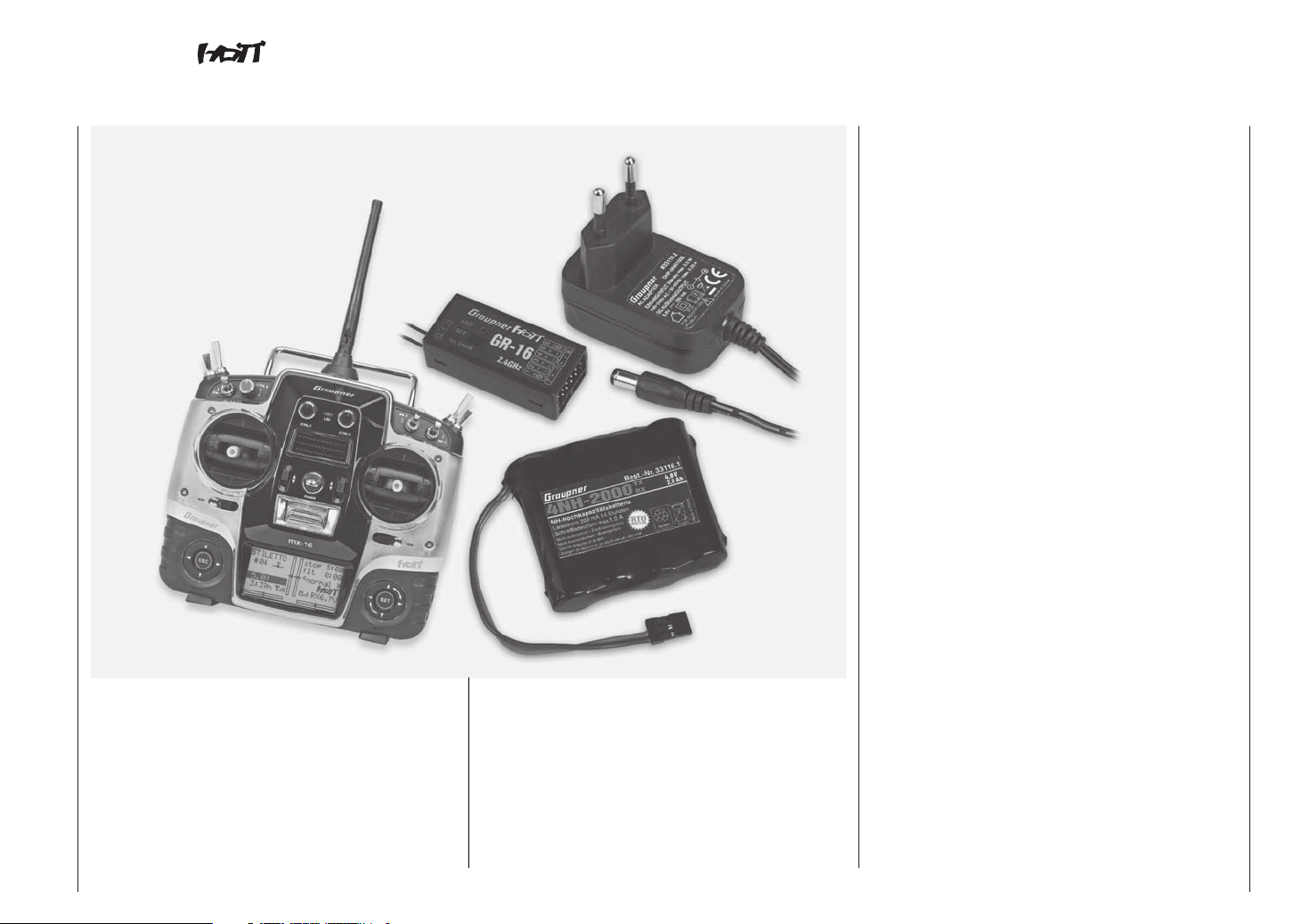
mx-16 the latest generation of radio control technology
HoTT (Hopping Telemetry Transmission) is the synthesis of expertise, engineering and world-wide testing by
professional pilots. The equipment operates on the 2.4
GHz band, and offers bi-directional communication between transmitter and receiver via a down-link channel
integrated into the receiver.
The mx-16 HoTT RC system is based on the
Graupner/JR mc-24 computer radio control system
which was introduced back in 1997. It has been developed specifically for the beginner, but the mx-16
HoTT is still capable of controlling all current model
types without problem - whether fixed-wing model or
helicopter, model boat or car.
In the area of fixed-wing models and helicopters it is
often necessary to employ complex mixer functions
for the control surfaces or the swashplate actuation
system. Computer technology enables you to activate
a vast range of functions to cope with special model
requirements – just by pressing a button. With the mx-
16 HoTT all you do is select the appropriate model
type, and the software then presents you automatically
with the appropriate mixer and coupling functions. This
means that the transmitter requires no additional modules in order to implement complex coupled functions,
and you can forget all about old-fashioned mechanical
mixers in the model. The mx-16 HoTT provides an
extremely high level of safety and reliability in use.
The mx-16 HoTT offers twenty model memories, each
of which can store model settings for different flight
phases. Individual phases can be called up in flight
simply by operating a switch, so that you can try out
various settings quickly and without risk. This can be
for test purposes or for varying parameters for different
phases of flight.
The large graphic screen makes operating the transmitter a simple, intuitive process. Mixers and other
functions can be displayed in graphic form, and this is
extraordinarily helpful.
The beginner quickly becomes familiar with the different
functions thanks to the clear, logically arranged program structure. Four-way touch-sensitive buttons to left
and right of the high-contrast screen are used to enter
settings, allowing the user to exploit all the options he
needs, in accordance with his experience in handling
radio-controlled models.
In theory the Graupner|SJ HoTT process allows more
than 200 models to be operated simultaneously. Although in practice the mixed operation of different technical systems in the 2.4 GHz ISM band – as required
by the approval regulations – reduces this number
considerably. Generally, however, it will always be
possible to operate even more models simultaneously
on the 2.4 GHz band than on the 35 / 40 MHz frequency
bands which we have used to date. However, the actual
limiting factor – as it has always been – is likely to
remain the size of the (air-) space available. The simple
fact that no frequency control procedure is necessary
equates to an enormous gain in safety, especially at
flying sites such as gliding slopes where groups of pilots
may be distributed over a large area, with nobody in
overall control.
The integral Telemetry menu provides a simple means
of accessing data and programming HoTT receivers.
For example, this method can be used to map receiver
outputs, distribute control functions to multiple servos,
and match servo travels and directions to each other.
This manual describes each menu in detail, and also
provides dozens of useful tips, notes and programming
examples to complement the basic information. More
general modelling terms, such as Transmitter controls,
Dual-Rates, Butterfly (Crow) and many others, are all
explained in the manual.
Please refer to the Appendix for additional information
on the HoTT system. This manual concludes with the
transmitter’s conformity declaration and guarantee
certificate.
Please read the safety notes and the technical information. We recommend that you read right through the
instructions with great care, and check all the functions
as described in the text. This can be carried out simply
by connecting servos to the supplied receiver, and
watching their response as you program the transmitter.
However, please read the notes on page 20 in this
regard. This is the quickest method of becoming familiar
with the essential procedures and functions of the mx-
16 HoT T.
Always handle your radio-controlled model with a
responsible attitude to avoid endangering yourself and
others.
The Graupner team wishes you great pleasure and success with your mx-16 HoTT - a radio control system of
the latest generation.
Kirchheim-Teck, February 2013
10
Introduction
Page 11
mx-16 Computer System
Eight-channel radio control set with Graupner|SJ HoTT 2.4 GHz technology (Hopping Telemetry Transmission)
• Micro-computer radio control system exploiting the
latest Graupner|SJ HoTT 2.4 GHz technology
• Bi-directional communication between transmitter
and receiver
• Five different languages
English, French, German, Italian and Spanish
• Ultra-fast response times through direct, ultra-reliable
data transmission from the main processor to the
2.4 GHz RF module. No additional delay caused by
detours through a module processor.
• Telemetry menu for displaying telemetry data, and
programming receiver outputs and optional sensors.
• Telemetry display shows numerous programming and
analysis functions directly on the transmitter screen.
• Speech output can be called up using freely programmable switches
• User-selectable servo cycle times for digital servos,
min. 10 ms
• Short, folding aerial
• Methods of operation and programming based on the
proven concepts of the mc-19 to mc-24
• High-contrast graphic screen with blue backlighting
ensures perfect monitoring of set-up parameters,
such as model type, model memory, timers and
operating voltage.
Graupner|SJ HoTT technology offers extreme
reliability in use, with bi-directional communication
between transmitter and receiver, integrated telemetry, speech output via earphone socket and ultrafast response times.
Simplified programming technology with capacitive
programming touch-buttons.
High-contrast, eight-line graphic screen with blue
backlighting for ultra-clear display of all set-up parameters and telemetry data. Telemetry data is stored
on a micro-SD memory card.
USB socket for reading out and saving model memory data, and loading firmware updates.
• Function encoder with two four-way touch-sensitive
buttons for simplified programming and accurate
settings
• Key-Lock function to guard against accidental operation.
• Four programmable flight phases
• Twenty model memories, with storage of all model-specific programming and set-up parameters
Description of radio control set
11
Page 12

mx-16 Computer System
Eight-channel radio control set with Graupner|SJ HoTT 2.4 GHz technology (Hopping Telemetry Transmission)
• Seven switches (two three-way switches, three twoway switches and two momentary switches), plus
three digital controls - already installed and extremely
versatile
• Unrestricted assignment of all switches to switched
functions simply by operating the appropriate switch
• Internal real-time clock for dating log files
• User-replaceable CR2032 buffer battery for internal
real-time clock
• Storage of model memories using the latest battery-free back-up system
• Eight control functions with simplified, very convenient assignment of transmitter controls for auxiliary
functions, such as switches and proportional controls
• Convenient mode selector provides simple method
of changing the stick mode (modes 1 - 4, e. g. throttle
right / throttle left).
When you change modes, all the affected settings
are switched at the same time.
• Graphical servo display provides a straightforward
overview of the servo set-up, and a swift method of
checking servo travels
• Receiver output swap
• Comprehensive programs for fixed-wing model
aircraft and helicopters:
Fixed-wing menu for: 1 AIL, 1 AIL + 1 FLAP, 2 AIL, 2
AIL + 1 or 2 FLAP, V-tail, delta / flying wing, two elevator servos
Fixed-wing mixer: diff aile, diff.flaps, ail rudd, ail
flaps, brake elev, brake flap, brake aile,
elev flap, elev aile, flap elev, flap aile
and diff. reduction
• Heli menu: 1-point, 2-point, 3-point and 4-point
linkages (1 servo, 2 servo, 3sv(2roll), 3sv(140°),
3sv(2nick (pitch-axis)), 4 SV (90°))
• Swashplate limiter
• Servo travel adjustment +/- 150% for all servo outputs, variable separately for each side (Single Side
Servo Throw)
• Variable sub-trim, range +/- 125%, for adjusting the
neutral position of all servos
• Servo reverse, programmable for all servos
• EXPO / DUAL-RATE system, separately variable, can
be switched in-flight, flight phase programmable
• Stopwatch / count-down timer with alarm function
• Model memory copy function
• Integral DSC socket for use with flight simulators and
Trainer systems
General features of the HoTT system
• Simple, ultra-fast binding of transmitter and receiver
• Multiple receivers can be bound per model for parallel operation
• Extremely fast re-binding, even at maximum range
• Two-receiver satellite operation using special cable
connection
• Range-check and warning function
• Receiver low-voltage warning on transmitter screen
• Ultra-wide receiver operating voltage range: 3.6 V to
8.4 V (fully operational down to 2.5 V)
• Fail-Safe
• Unrestricted channel assignment (channel-mapping),
mixer functions and all servo settings programmable
in the Telemetry menu
• Up to four servos can be actuated simultaneously
as a block, with a servo cycle time of 10 ms (digital
servos only)
• Optimised frequency hopping and broad channel
spread for maximum interference rejection
• Intelligent data transmission with corrective function
• Real-time telemetry analysis
• More than 200 systems can be operated simultaneously
• Future-proof update capability using USB port
Description of radio control set
12
Page 13
The set Order No. 33116 contains
mx-16 HoTT micro-computer transmitter with integral
4NH-2000 RX RTU flat-pack NiMH transmitter battery,
Order No. 33116.2 (specification reserved), plug-type
battery charger (5,6 V / 200 mAh), Graupner|SJ GR-16
HoTT bi-directional receiver, Order No. 33508, micro-SD
card, USB interface, Order No. 7168.6 and adapter lead,
Order No. 7168.6S.
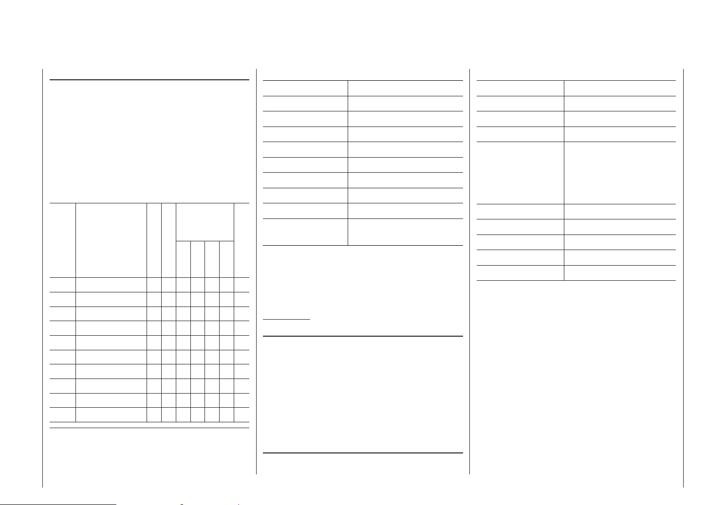
Recommended battery chargers (optional)
Suitable for
the following
battery types
Order
No. Description
220 V mains conn.
12 V DC connect.
NiCd
NiMH
LiPo
Lead-ac.
6411 Ultramat 8 x x x x x
6463 Ultramat 12 plus x x x x x x
6464 Ultramat 14 plus x x x x x x x
6466 Ultra Trio plus 14 x x x x x x x
6468 Ultramat 16S x x x x x x x
6469 Ultra Trio Plus 16 x x x x x x
6470 Ultramat 18 x x x x x x x
6475 Ultra Duo Plus 45 x x x x x x x
6478 Ultra Duo Plus 60 x x x x x x x
6480 Ultra Duo Plus 80 x x x x x x x
Specification, mx-16 HoTT transmitter
Frequency band 2,4 … 2,4835 GHz
Modulation FHSS
Transmitter power 100 mW EIRP
Control functions Eight functions; four with trims
Temperature range -10 … +55°C
Aerial folding
Operating voltage 3,4 … 6 V
Current drain approx. 180 mA
Dimensions approx. 190 x 195 x 90 mm
Weight approx. 770 g with transmitter
battery
Integral charge. lead
Accessories
Order No. Description
1121 Neckstrap, 20 mm wide
70 Neckstrap, 30 mm wide
3097 Wind-shield for hand-held transmitter
Trainer leads for mx-16 HoTT:
see page 157
Specification, GR-16 HoTT receiver
Operating voltage 3,6 … 8,4 V*
Current drain ca. 70 mA
Frequency band 2,4 … 2,4835 GHz
Modulation FHSS
Aerial Diversity aerials,
2 x approx. 145 mm long,
approx. 115 mm encapsulated and approx. 30 mm
active
Servo sockets 8
Sensor socket 1
Temperature range approx. -10° … +55°C
Dimensions approx. 46 x 21 x 14 mm
Weight approx. 12 g
* The permissible operating voltage range stated above applies to
the receiver only! Please note in this regard that the receiver’s input
voltage is passed directly (i.e. unregulated) to the servo sockets, but
the permissible operating voltage range of the overwhelming majority of servos, speed controllers, gyros etc. which can be connected
to the receiver is only 4.8 to 6 Volt!
To charge the batteries you will also need the transmitter charge lead,
Order No. 3022 and the receiver charge lead, Order No. 3021.
For details of additional battery chargers, and details of the chargers
listed here, please refer to the main Graupner FS catalogue, or our
Internet site at www.graupner.de/en.
Replacement parts
Order No. Description
2498.4FBEC 4NH-2000 RX RTU, flat-pack
33800 HoTT transmitter aerial
For information on additional accessories please refer to
the Appendix or visit our Internet site at www.graupner.
de/en. Alternatively you can enquire at your local model
shop, where the staff will be pleased to advise you.
Description of radio control set
13
Page 14
Operating Notes
Transmitter power supply
The mx-16 HoTT transmitter is fitted as standard with
a high-capacity rechargeable 4NH-2000 RX RTU NiMH
battery (Order No. 2498.4FBEC) (specification reserved). When delivered, the standard rechargeable
battery is not charged.
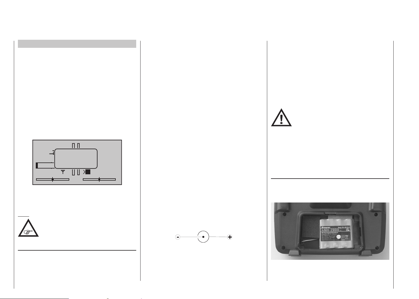
When you are using the transmitter you can monitor
the battery voltage on the LCD screen. If the voltage
of the transmitter battery falls below a certain voltage
(default 4.7 V), which can be set in the “Battery warning
threshold” line of the “Basic settings” menu, page 134,
you will hear an audible warning signal. The screen then
displays a message reminding you that the transmitter
battery needs to be recharged.
stop
#01
0:22h
Always recharge the transmitter battery in good time.
When you see this message, cease operations immediately and recharge the transmitter battery.
Note:
Ensure that the correct battery type is set in
the “Basic settings” menu on page 134!
NIMH must be set as the standard value.
4.7
battery
needs
charging!!
x
Mx
0:00
0:00
HoTT
0.0V
inside the transmitter for charging, to avoid premature
damage to the internal battery socket.
As an approximate guideline a discharged battery
should be charged for twelve hours at a current corresponding to one tenth of the capacity printed on the
pack. If you are using the standard transmitter battery
and the charger supplied in the set, this current is
200 mA.
Never use charger plugs of other manufacturers or
chargers designed for other battery types. If the output
voltage is too high, or if the plug has any incorrect
polarity (see below), immense damage can result. We
recommend labelling the charger plug accordingly as
needed.
The transmitter must be switched “OFF” for the whole
period of the charge process. Never switch on the
transmitter when it is still connected to the charger; even
a very brief interruption in the process can cause the
charge voltage to rise to the point where the transmitter
is immediately damaged. For this reason check carefully
that all connectors are secure, and are making really
good contact.
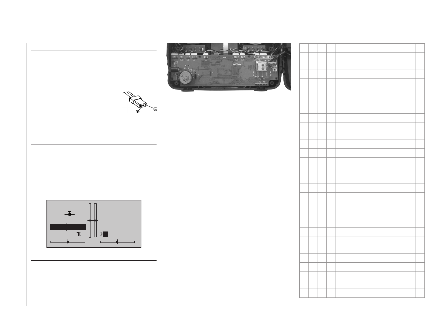
Polarity of the mx-16 HoTT charge socket
Commercially available battery charge leads produced
by other manufacturers are often made up with the opposite polarity. For this reason it is essential to use only
the genuine Graupner charge lead, Order No. 3022.
voltage of the battery. The maximum charge current
must not exceed 1 A, otherwise the diode and possibly
other components may be damaged.
If possible, set the delta peak voltage difference of your
fast charger to a value in the range 10 mV … 20 mV or
equivalent, as described in the charger’s instructions;
this ensures that it is suitable for fast-charging NiMH
cells.
ATTENTION:
First connect the banana plugs on the
charge lead to the charger, and only then
connect the other end of the charge lead
to the charge socket on the transmitter. When the
charge lead is connected to the transmitter, never
allow the bare ends of the plugs to touch! To avoid
damage to the transmitter, the charge current must
never exceed 1 A. If necessary, limit the current on
the charger itself.
Removing the transmitter battery
To remove the transmitter battery, first disengage the
cover over the battery compartment on the back of the
transmitter, then lift it off:
Charging the transmitter battery
The rechargeable NiMH transmitter battery can be
recharged with the battery charger (Order No. 33116.2)
supplied in the set, using the charge socket located on
the right-hand side of the transmitter. Leave the battery
Operating Notes
14
Using automatic battery chargers
As standard the charge socket is protected against
short-circuit by a diode. However, genuine Graupner
automatic battery chargers are still able to detect the
Remove the battery, then carefully pull on the power
lead to disconnect the transmitter battery connector.
Page 15
Installing the transmitter battery
Hold the connector attached to the transmitter battery in
such a way that the black or brown wire faces the aerial,
and the unused socket of the battery connector is on the
side facing the bottom, then push the battery connector
onto the three pins projecting out of the inside of the
transmitter, in the direction of the circuit
board. (The battery connector is
protected against reversed polarity by
two chamfered edges; see illustration).
Finally place the battery in the compartment, and close the cover.
Polarity of
transmitter battery
connector
Battery timer, bottom left corner of the screen
This timer displays the cumulative operating time of the
transmitter since the last time the transmitter battery
was charged.
This timer is automatically reset to “0:00” when the
transmitter detects that the voltage of the transmitter
battery is significantly higher than the last time it was
switched on, e. g. as a result of a charge process.
The purpose of this battery is to protect the system from
loss of date and time if the transmitter’s power supply is
disconnected; for example, when the transmitter battery
is replaced.
0:00
0:00
#01
stop
flt
5.6V
0:00h
Mx
HoTT
0.0V
CR 2032 lithium battery
On the left-hand side of the transmitter circuit board you
will find a holder fitted with a user-replaceable CR 2032
lithium battery:
Operating Notes
15
Page 16
Operating Notes
Receiver power supply
A wide range of rechargeable four-cell and five-cell NiMH
batteries varying in capacity is available for use as the
receiver power supply. If you are using digital servos we
recommend that you use a five-cell (6 V) pack of generous capacity. If your model is fitted with a mixture of
digital and analogue servos, it is important to check the
maximum permissible operating voltage of all the types.
The PRX unit, Order No. 4136, provides a stabilised
receiver power supply with a user-variable voltage from
one or two receiver batteries; see Appendix.
For reasons of safety battery boxes or dry cells should
never be used.
The voltage of the airborne power supply is displayed on
the transmitter screen while the model is flying:
stop
#01
5.2V
2:22h
If the voltage falls below the pre-set warning threshold - 3.8 Volt as standard, but variable in the Telemetry
menu; see page 146 - a visual and audible low-voltage
warning is triggered.
Nevertheless it is important to check the
state of the batteries at regular intervals.
Don’t put off charging the batteries until
the warning signal is triggered.
Note:
Please refer to the main Graupner FS
catalogue or visit the Internet site at www.
graupner.de/en for full details of batteries,
Operating Notes
16
flt
M
0:00
0:00
HoTT
5.5V
chargers, measuring equipment and battery monitor
units.
Charging the receiver battery
The charge lead, Order No. 3021, can be connected
directly to the NC receiver battery for charging. If the
battery is installed in a model and you have installed one
of the following switch harnesses: Order No. 3046, 3934
or 3934.1 or 3934.3, the battery can be charged via the
separate charge socket, or the charge socket which is
built into the switch. The switch on the switch harness
must be left at the “OFF” position for charging.
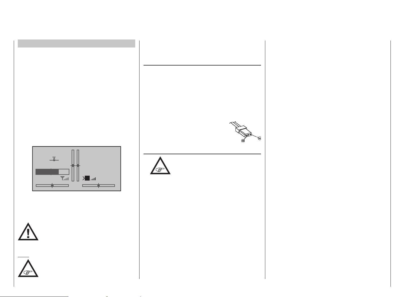
Polarity of the receiver battery connector
General notes on battery charging
•
• Keep to the maximum permissible charge current
stated by the battery manufacturer.
• The maximum charge current for the transmitter
battery is 1.5 A. Limit the charge current to this value
on the charger.
• If you wish to charge the transmitter battery at a
current higher than 1.5 A, you must first remove the
pack from the transmitter, otherwise you risk damaging the circuit board through overloading the conductor tracks, and / or overheating the battery.
• Carry out a series of test charges to ensure that the
automatic charge termination circuit works correctly
with your battery. This applies in particular if you are
using an automatic charger designed for NiCd batteries to recharge the standard NiMH battery.
Observe the recommendations provided
by the charger manufacturer and the
battery manufacturer at all times.
• You may need to adjust the charger’s termination
behaviour, if it provides this option.
• Do not discharge the battery or carry out a battery
maintenance program via the integral charge socket.
The charge socket is not suitable for this application.
• Always connect the charge lead to the charger first,
and only then to the transmitter or receiver battery.
Observing this rule eliminates the danger of accidental short-circuits between the bare contacts of the
charge lead plugs.
• If the battery becomes hot when on charge, it is time
to check the pack’s condition. Replace it if necessary,
or reduce the charge current.
• Never leave batteries unsupervised when on
charge.
• Read and observe the safety notes and handling
information in the section starting on page 8.
Page 17
Adjusting stick length
Both sticks are infinitely variable in length over a broad
range, enabling you to set them to suit your personal
preference.
Hold the bottom half of the knurled grip firmly, and
unscrew the top section:
Now screw the stick top in or out (shorter or longer)
to the length you prefer before tightening the top and
bottom sections against each other to fix the stick top.
Opening the transmitter case
Please read the following notes carefully before you
open the transmitter. If you have no experience in such
matters, we recommend that you ask your nearest
Graupner Service Centre to carry out the work for you.
The transmitter should only be opened in the following
cases:
• When a self-neutralising stick needs to be converted
to non-neutralising action, or a non-neutralising stick
to a self-neutralising action.
• If you wish to adjust the stick centring spring tension.
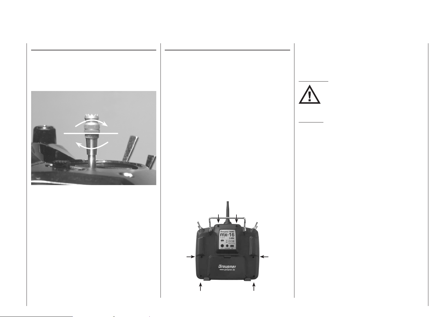
Before opening the transmitter check that it is switched
off (move Power switch to “OFF”).
Open the battery compartment and remove the transmitter battery as described on the previous double page,
together with any micro-SD card already installed.
After this, use a PH1-size cross-point screwdriver to
undo the six screws recessed into the back panel of the
transmitter, as shown in the illustration:
Arrangement of the case back screws
Hold the two case sections together with your hand, and
turn the unit over to allow these six screws to fall out
onto the table. Now carefully raise the case back and
fold it open to the right, as if you were opening a book.
ATTENTION:
Two multi-core cables connect the lower
shell to the transmitter electronics located in the top section. Please take great
care not to damage this cable!
Important:
• Do not modify the transmitter circuit in any way,
as this invalidates your guarantee and official approval for the system.
• Do not touch any part of the circuit boards with
any metal object. Avoid touching the contacts
with your fingers.
• Never switch the transmitter on while the case is
open.
Please note the following points when closing the
transmitter:
• Make sure that no cables are jammed between the
transmitter case sections when you close the back.
• Check that the two case sections fit together flush all
round before fitting the retaining screws. Never force
the two case components together.
• Fit the case screws in the existing threads, and tighten them gently. Over-tightening them will strip the
threads in the plastic.
• Remember to re-connect the battery.
Operating Notes
17
Page 18
Operating Notes
Folding aerial
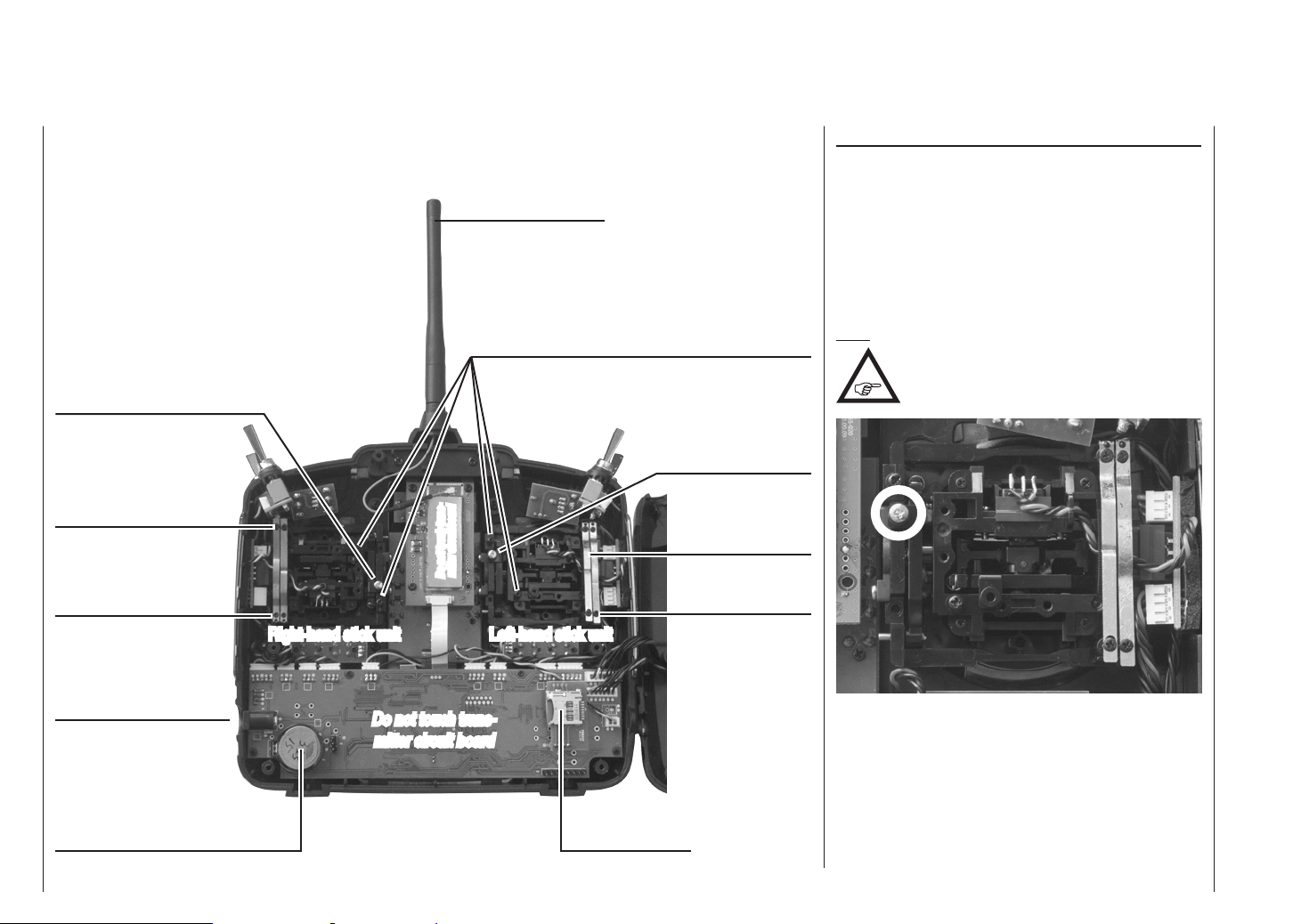
Converting the dual-axis stick units
Self-centring action
Either or both sticks can be converted from self-neutralising to non self-neutralising action: start by opening the
transmitter as described on the previous page.
If you wish to change the standard stick unit arrangement, start by locating the screw on the left-hand stick
unit shown circled in white in the photo below.
Self-centring screw
Brake springs
Adjuster screws
Right-hand stick unit
Charge socket
User-replaceable CR2032 lithium
cell, acting as buffer battery for the
integral real time clock
mitter circuit board
Do not touch trans-
Do not touch trans-
mitter circuit board
Adjuster screws for stick centring force
Left-hand stick unit
Memory card slot
Note:
The right-hand stick unit is buitl-in turned of
about 180 °, i. e. the screw you require is
located on the right, below centre.
Self-centring screw
Brake springs
Adjuster screws
Turn this screw clockwise until the stick on that side
moves freely from one end-stop to the other; alternatively unscrew it until the stick is fully self-centring again.
Operating Notes
18
Page 19
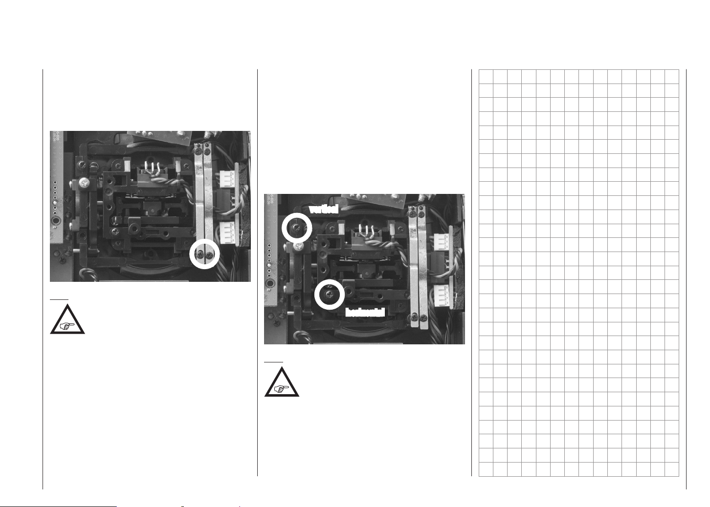
Brake spring and ratchet
You can alter the braking force of the stick by adjusting
the outer of the two screws circled in white in the next
picture; adjusting the inner screw alters the strength of
the ratchet:
Note:
The right-hand stick unit is buitl-in turned of
about 180 °, i. e. the screw you require is
located on the right, below centre.
Stick centring force
The centring force of the sticks is also variable to suit
your preference. The adjustment system is located
adjacent to the centring springs; see the white circles in
the following photo.
You can set the preferred centring spring force by rotating the corresponding adjuster screw using a cross-point
screwdriver:
• Turn to the right = harder spring tension;
• Turn to the left = softer spring tension.
vertical
horizontal
Note:
The right-hand stick unit is buitl-in turned of
about 180 °, i. e. the screw you require is
located on the right, below centre.
Operating Notes
19
Page 20
Description of transmitter
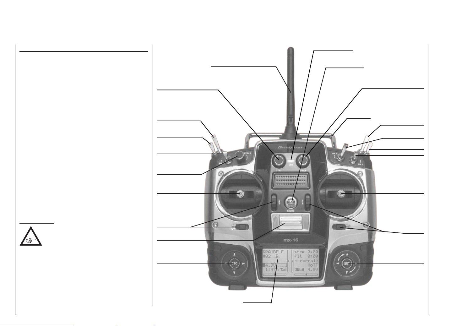
Front of transmitter
Attaching the transmitter neckstrap
You will find a strap lug mounted in the centre of the
front face of the mx-16 HoTT transmitter, as shown in
the drawing on the right. This lug is positioned in such a
way that the transmitter is perfectly balanced even when
suspended from a neckstrap.
Order No. 1121 Neckstrap, 20 mm wide
Order No. 70 Neckstrap, 30 mm wide
Important note:
In the transmitter’s standard form any servos
connected to the receiver can initially only be
operated using the dual-axis sticks. For
maximum flexibility, all the other transmitter controls
(CTRL 6 ... 8, SW 1 ... 9) are “free” in software terms,
and can be assigned to any channels you like, enabling
you to set up the system to suit your personal preference or the requirements of a particular model. This is
carried out in the “contr set.” menu, as described on
pages 94 (fixed-wing models) and 96 (model
helicopters).
Description of transmitter
20
Aerial with folding / rotating base
Rotary proportional control CTRL 7
2-position switch SW 8
3-position switch SW 4/5
2-position momentary
switch SW 1
Rotary proportional
control CTRL 6
Left-hand stick
Trim
ON / OFF switch
Left-hand touch-button
Central Status LED
Neckstrap lug
Rotary proportional control CTRL 8
Carry handle
2-position switch SW 9
2-position switch SW 2
3-position switch SW 6/7
2-position switch SW 3
Right-hand stick
Trim
Right-hand touch-button
LCD screen
Page 21
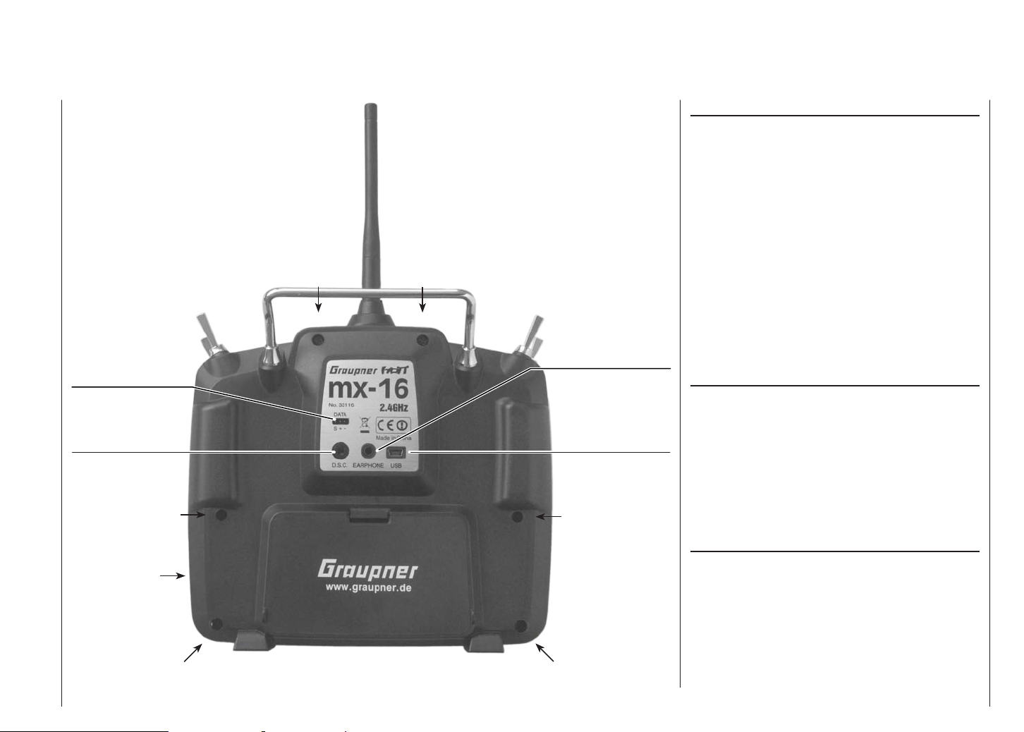
Rear of transmitter
Data socket for connecting Smart-Box, Order
No. 33700
DSC socket for connecting flight simulators and
for Teacher mode
Case screw
Case screw
Case screw
Earphone / headphone
socket
Five-pin mini-USB
socket for connecting
transmitter to a PC
Case screw
Headphone socket
The central socket at the bottom edge of the back panel
name plate is intended for connecting a standard commercial earphone or headphones fitted with a 3.5 mm
barrel plug (not included in the set).
Signals and voice messages associated with the
Telemetry menu are generated via this socket, as are
the transmitter’s audible signals. The default language
for speech output is German. For more information on
this please refer to “Voice messages” in the “HIDDEN
MODE” section starting on page 26, and the “Telemetry” section starting on page 137.
The volume of the headphone output can be adjusted
in the “Voice volume” line of the “Basic settings” menu;
see page 135.
mini-USB socket
This socket can be used to connect the transmitter to
a PC running Windows XP, Vista or 7. The software
required at the PC, including a suitable USB driver, can
be found in the Download section for that product at
www.graupner.de/en.
Once you have installed the software required, you can
update the transmitter via this connection as and when
required, or simply set the correct date and time of day.
Transmitter battery
charge socket
Case screw
Battery compartment cover
Case screw
Data socket
For connecting the optional Smart-Box, Order No. 33700.
For more details about the Smart-Box please refer to the
main Graupner FS catalogue, or refer to that product on
the Internet at www.graupner.de/en.
Description of transmitter
21
Page 22
DSC socket
Connenction socket for flight simulators or trainer systems
The original function of this socket was for “Direct Servo
Control”, and that’s why the abbreviation is still in use.
However, for technical reasons “direct servo control” is
no longer possible with the HoTT system using a diagnosis lead.
The mx-16 HoTT transmitter’s standard two-pole DSC
socket is now used as a Trainer (buddy box) socket
(Teacher or Pupil), and as an interface for flight simulators.
For the DSC connection to work you must check the
following:
1. Carry out any adjustments required in the appropri-
ate menus:
See page 154 for information on setting up the
mx-16 HoTT transmitter to work as part of a Trainer system.
2. ALWAYS leave the transmitter’s On / Off switch in
the “OFF” position when using a flight simulator, and
when using the mx-16 HoTT transmitter as a Pupil unit in a Trainer system, for only in this position is
the RF section of the transmitter module switched off
(no RF signal) even when the DSC lead is plugged
in. At the same time the transmitter’s current drain is
reduced slightly.
The central Status LED should now glow a constant red, and the abbreviation “DSC” appears in the
transmitter’s base display on the left, below the model number. At the same time the display of telemetry
symbols is suppressed:
3. Connect the other end of the connecting lead to the
Note regarding flight simulators:
contacts at the barrel connector or the DSC module.
This work must be carried out by a Graupner Service
Centre.
PUPIL
#11
DSC
5.6V
0:01h
The transmitter is now ready for use.
In contrast, when the mx-16 HoTT is used in
Teacher mode, the transmitter must be switched on
before the appropriate cable is plugged in.
appropriate apparatus, taking into account the operating instructions supplied with that device.
Important:
Ensure that all connectors are firmly seated in
their sockets.
The range of flight simulators available
commercially is now very wide, and you may
find that it is necessary to swap over certain
stop
flt
0:00
0:00
HoTT
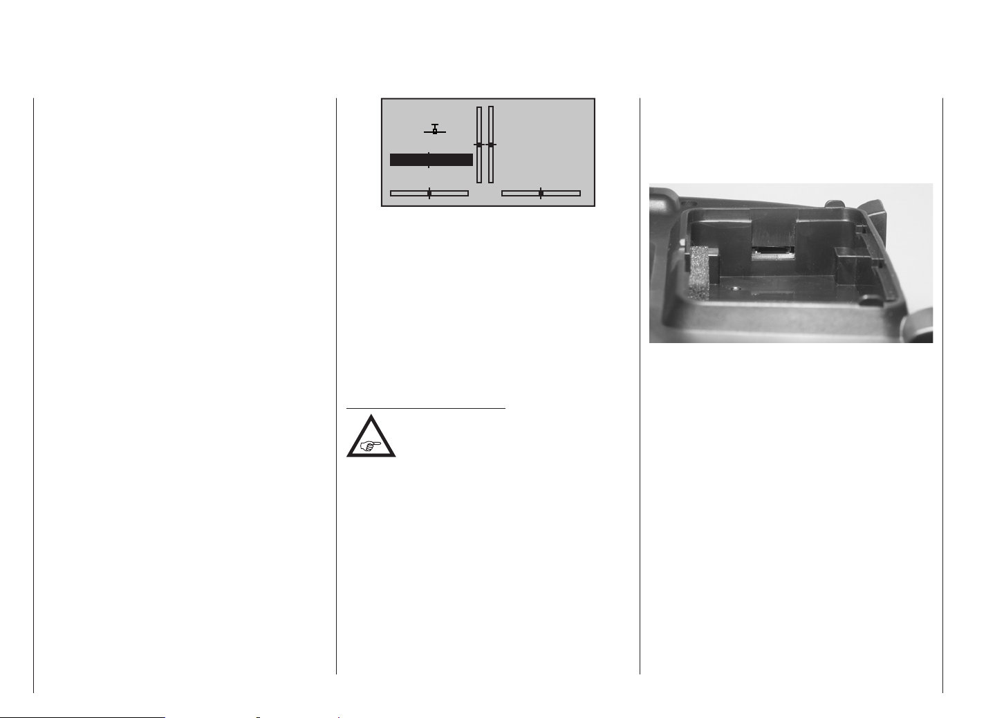
Card slot
Data storage
micro-SD and micro-SDHC
When you switch off the mx-16 HoTT transmitter and
remove the battery compartment cover, you will see
the card slot for memory cards (of the micro-SD and
micro-SDHC type) in the right-hand side of the compartment:
In addition to the memory card supplied as standard, it
is possible to use any standard commercial micro-SD
memory card with a capacity of max. 2 GB, and any micro-SDHC card with a capacity of up to 32 GB. However,
the manufacturer recommends the use of memory cards
with capacities up to only 4 GB, as these are completely
adequate in all normal circumstances.
The memory cards for which the transmitter is intended
are familiar from their use in digital cameras and mobile
telephones. Place the card in the slot with the contacts
facing up, towards the back panel, and push it in until
it locks. When the battery has been installed and the
battery compartment closed, switching the transmitter
on causes a number of folders to be created on the
memory card. At the same time a stylised memory card
graphic appears in the base display to indicate that a
memory card is inserted.
Description of transmitter
22
Page 23
stop
#01
5.2V
3:33h
Note:
If there is an SD card installed, withdraw it
BEFORE you remove the transmitter’s back
panel, otherwise there is a risk that you will
damage the card.
Prepare the memory card as described, remove it from
the transmitter, and insert it in a suitable card reader.
Make sure the reader is connected to your PC or laptop, and copy the files previously downloaded from the
Download page for your transmitter into the appropriate
folder. Finally remove the memory card from the card
reader, and replace it in the transmitter.
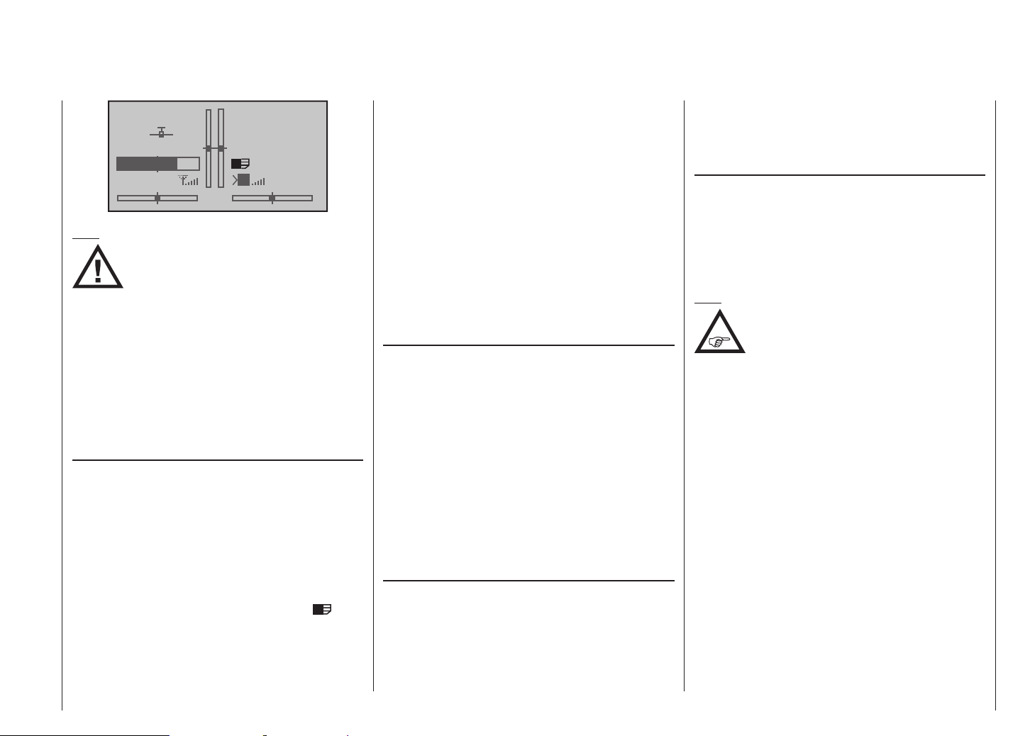
Data recording / storage
The process of saving data on the SD card is coupled to
the flight timer: if the timer is started, then data saving
commences - provided that a suitable memory card
is in the card slot, and a telemetry connection to the
receiver exists - and ceases again when the flight timer
is stopped. The flight timer is started and stopped as
described in the “Timers” section on page 77 for fixedwing models, and pages 86 for model helicopters.
When data is being recorded, the card symbol
flashes constantly and slowly.
When data is being written to the memory card, the
memory card symbol swells from left to right to indicate
the process.
flt
M
0:00
0:00
HoTT
5.5V
When a data storage process is concluded, you will find
an (empty) “Models” folder and a “Log-Data” folder on
the memory card. The latter contains the log files, stored
in sub-folders named “Model name”, using the format
0001 Year-Month-Day.bin, 0002 Year-Month-Day.bin etc.
However, if a model memory has not yet been named,
then you will find the associated log files in a sub-folder
named “NoName” when you remove the memory card
from the transmitter and insert it in the card slot of a PC
or laptop. The data can subsequently be analysed on a
compatible PC using the PC program available on the
Download page for the transmitter at www.graupner.de/
en.
Firmware updates / Changing the screen language
It is possible to replace and / or update the transmitter’s
firmware - and the transmitter’s screen language, if
necessary - under menu control, as described in detail
on page 27 under the title “Firmware update” in the
“Hidden Mode” chapter. In addition to a German version of the firmware, the SD card supplied in the set as
standard also contains firmware versions in English,
French, Italian and Spanish; this information was correct
at the time these instructions went to press.
Corresponding updates and information can be found
in the Download area of www.graupner.de/en under the
product concerned.
Importing voice files
As mentioned in the “Headphone socket” section on
page 21, the signals associated with the Telemetry
menu and voice messages can be generated via this
socket, in addition to the transmitter’s audible signals.
These voice messages are collected in a voice package
and stored in the transmitter’s internal memory, but they
can be replaced by a voice package in another language
at any time. For more information on this please refer to
the “HIDDEN MODE” section starting on page 26.
Importing and exporting model memories
Any model memories can be copied onto a memory
card in the transmitter, or copied from the card into the
transmitter, so that you can exchange data between
identical transmitters, and also back up your data. For
more information please see the “Model memories”
section starting on page 70.
Note:
Some of the special characters used in
certain model names cannot be accepted
due to specific limitations of the FAT or
FAT32 file system used by memory cards. During the
copy process they are replaced by a tilde (~) character.
Description of transmitter
23
Page 24
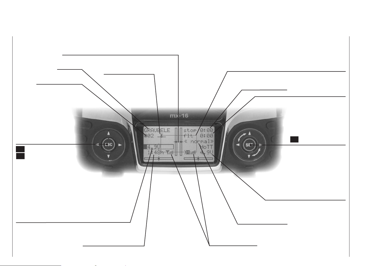
Screen and keypad
Visual display of the trim lever positions; alternatively - if rotary controls CTRL 7 … 9 are operated - display of the current
settings of these two controls
Model name
Model memory 1 … 20
Left-hand touch-key
leaf through
pressed briefly together:
switches to Servo display
menu
ESC = interrupt / back
ESC touched for about three
seconds; Switches to the
Telemetry menu, and
back to the base display
Battery voltage
(If battery voltage falls below a particular level, you will see a
warning display - see “Warning notes” on page 36. At the
same time the transmitter emits an audible warning signal.)
Model type display
(fixed-wing / helicopter)
See page 36 for possible warnings
Stopwatch in min:sec
(count-up / count-down)
Flight phase name
Switching between
flight phases using switch
Flight timer in min:sec
(count-up / count-down)
Right-hand touch-key
leaf through / alter values
SET Select / Confirm
Simultaneous brief press of
or = CLEAR
Receiver power supply voltage
Battery operating time since
last battery charge, in hr:min
Description of transmitter - screen and keypad
24
Signal strength indicator
Page 25
Operating the “Data Terminal”
Input buttons ESC and SET
symbols
On-screen telemetry symbols
The active model memory has not yet been
“bound” to a HoTT receiver. See page 80
or 88 for more information on the “binding”
process.
Not flashing: RF switched off at transmitter
Flashing aerial symbol:
The last receiver bound to the active model is
inactive, or out of range
>M x No telemetry signal detected
Signal strength display
>M
Display of Pupil signal strength on the Teacher
>P
transmitter’s screen.
Buttons to the left of the screen
• ESC button
A brief press on the ESC button returns you step by
step within the function select system, taking you
right back to the basic display. If you make a change
in the meantime, the change is retained.
If touched for about three seconds in the base display, ESC opens and closes the Telemetry menu.
• Arrow buttons
1. A brief press on one of these buttons allows you
to leaf through lists, such as the Model Select or
Multi-Function list, always moving in the direction
of the arrow; the arrow buttons are also used to
move through menu lines within menus.
2. A brief simultaneous press of the buttons
switches from the base transmitter display, and
from almost any menu position, into the “Servo
display” menu.
Buttons to the right of the screen
• SET button
1. Starting from the base screen display - as it appears when you switch the transmitter on - a brief
press of the SET button takes you to the multi-function menus. You can also call up a selected
menu using the SET button.
2. Within the set-up menus you can activate (confirm) and disable the corresponding set-up fields
with a brief press of the SET button.
• Arrow buttons
1. “Leafs through” the multi-function menu and the
menu lines within the set-up menus, in the same
manner as the left-hand touch-key’s arrow buttons.
2. Selects and adjusts parameters in set-up fields after you have activated them by briefly pressing
the SET button; the buttons and are
assigned the same function in each case, i. e. it
makes absolutely no difference which of the two
buttons you use.
3. A brief simultaneous press of the or
buttons resets an altered parameter value in the
active input field to the default value (CLEAR).
Notes:
•
• If you switch the transmitter off and then immediately on again, you may find that the touch-keys have
no effect. This is not a fault! Switch the transmitter off
again, and wait a few seconds before switching it on
once more.
It is not the contact with the touch-key itself that triggers the corresponding action, but the cessation of the touch.
Short-Cuts
You can call up particular menus or options directly
using the following button combinations:
• CLEAR
A brief simultaneous press of the or but-
tons of the right-hand touch-key resets an altered parameter value in the active input field to the default
value.
• “Servo display”
A brief simultaneous press of the buttons of the
left-hand touch-key switches from the transmitter’s
base display, and from almost any menu position, to
the “Servo display”, menu; see page 133.
• “Telemetry”
Hold the central ESC button of the left-hand touch-
key pressed in for about one second in order to call
up the “Telemetry” menu from the transmitter’s base
display - see section starting on page 137 - and
also to return to it again.
• Graphic display of telemetry data
Briefly pressing the or button of the left or righthand touch-key switches directly from the transmitter’s base display to the graphic telemetry data display, and also leafs to and fro between the individual
graphic displays.
Press ESC to return to the base display.
• “HIDDEN MODE”
(language selection and contrast)
Simultaneously press the arrow buttons of the
left-hand touch-key AND the central SET button of
the right-hand touch-key; see next pagees.
• Input lock
Can be activated and disabled at the transmitter’s basic display by simultaneously holding the ESC and
SET buttons pressed in for about two seconds.
Description of transmitter - screen and keypad
25
Page 26
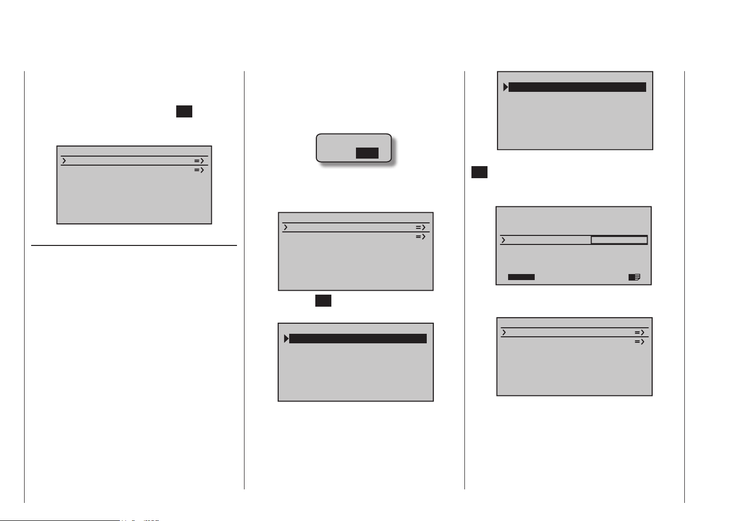
HIDDEN MODE
Language selection and screen contrast
The “HIDDEN MODE” (VERSTECKTER MODUS) menu
of the mx-16 HoTT transmitter can be accessed from
virtually any menu position by holding the arrow buttons
of the left-hand touch-key and the SET button of
the right-hand touch-key pressed in; after about one
second this display appears:
VERSTECKTER MODUS
ANSAGEN
FIRMWARE UPDATE
KNÜPPEL KALIBRIER.
VOICE
As mentioned in the “Headphone socket” section on
page 21, the signals associated with the Telemetry
menu and voice messages can be generated via this
socket, in addition to the transmitter’s audible signals.
The default language for these messages is German.
These voice messages are collected in a voice package
and stored in the transmitter’s internal memory, but they
can be replaced by a voice package in another language
at any time.
When this manual went to press, the following languages were available:
• English
• French
• German
• Italian
• Spanish
The currently active voice package can be exchanged
using either the PC program which is available at www.
graupner.de/en on the Download page for the transmit-
ter, or using the SD card supplied in the set, as described in the following section. If you have not already
done so, insert your SD or SDHC card in the transmitter,
as described on page 22. Switch the transmitter on
with RF switched off:
RF ON/OFF?
ON OFF
Changing the language
Use the arrow buttons of the left or right-hand touch-key
to move to the “VOICE” (“ANSAGEN”) line:
VERSTECKTER MODUS
ANSAGEN
FIRMWARE UPDATE
KNÜPPEL KALIBRIER.
Press the central SET button of the right-hand touch-key
to move to the Select page of the “VOICE” option:
DATEILISTE
VOICE2_ENGLISH.VDF
VOICE2_FRANCE.VDF
VOICE2_GERMAN.VDF
VOICE2_ITALIANO.VDF
VOICE2_SPAIN.VDF
Now use the arrow buttons of the left or right-hand
touch-key to select the language you prefer, for example:
DATEILISTE
VOICE2_ENGLISH.VDF
VOICE2_FRANCE.VDF
VOICE2_GERMAN.VDF
VOICE2_ITALIANO.VDF
VOICE2_SPAIN.VDF
Confirm your selection by briefly pressing the central
SET button of the right-hand touch-key again: the se-
lected voice package is now loaded into the transmitter’s
memory:
HIDDEN MODE
CONTRAST
LANGUAGE
VOICE
22/100%
0
ENGLISH
ENGLISH
I
The loading process is finished when the progress bar
at the bottom edge of the screen disappears:
VERSTECKTER MODUS
ANSAGEN
FIRMWARE UPDATE
KNÜPPEL KALIBRIER.
Finally switch the transmitter off to conclude the procedure.
All the settings stored in the transmitter are retained in
full even after you have switched languages.
Description of transmitter
26
Page 27
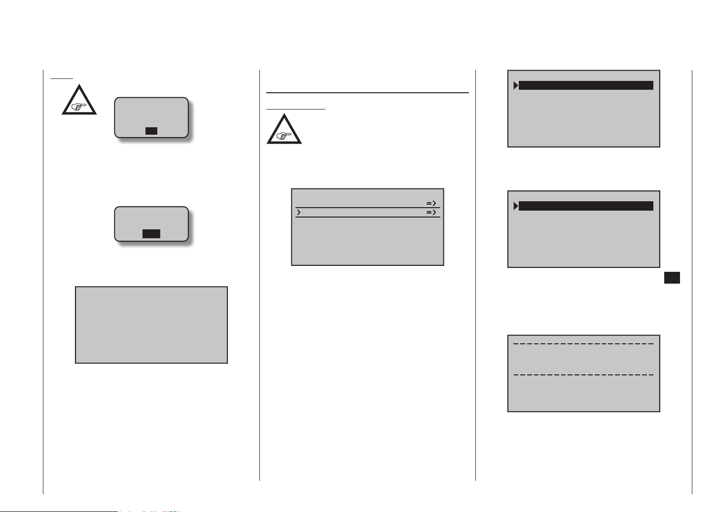
Notes:
•
If the warning message …
RF
MUST BE
OFF
OK
… appears, then the transmitter’s RF section is still
active. Switch this section off in the “RF module” line
of the “Base settings” menu, and repeat the proce-
dure.
• If the warning …
SD-CARD
INSERT
OK
… appears, then there is no memory card in the card
slot, or the card cannot be read.
• If the Select window is empty …
FILE LIST
… then the transmitter cannot find a suitable voice
file on the SD card in the transmitter. If this should
happen, check the contents of the “VoiceFile” folder
by inserting the SD card in a PC or laptop.
FIRMWARE UPDATE / Changing the screen language
Important note:
It is essential to check the state of charge
of your transmitter battery before you
carry out any update. For safety’s sake
recharge it and back up all occupied model memories, so that you can restore them if anything goes
wrong.
VERSTECKTER MODUS
ANSAGEN
FIRMWARE UPDATE
KNÜPPEL KALIBRIER.
It is possible to update and / or replace the transmitter’s
firmware, and with it the screen language, using this
menu point; the procedure is similar to that described in
the section entitled “VOICE”. When this manual went to
press, the following languages were present on the SD
card supplied as standard in the set:
• German
• English
• French
• Italian
• Spanish
Corresponding updates and further information can be
found at www.graupner.de/en on the mx-16 HoTT product page under Download.
DATEILISTE
MX-12_1V234_ENGLISH.
MX-12_1V234_FRANCE.B
MX-12_1V234_GERMAN.B
MX-12_1V234_ITALIANO
MX-12_1V234_SPAIN.BI
Use the arrow buttons of the left or right-hand
touch-key to select the firmware version you wish to use,
for example:
DATEILISTE
MX-12_1V234_ENGLISH.
MX-12_1V234_FRANCE.B
MX-12_1V234_GERMAN.B
MX-12_1V234_ITALIANO
MX-12_1V234_SPAIN.BI
Confirm your choice by briefly pressing the central SET
button of the right-hand touch-key once more. The selected firmware now starts to load into the transmitter’s
memory, and after two brief screen displays (which only
concern the start of the firmware update) you will see …
Firmware Download
Prozess Start
Please Wait....
Description of transmitter
27
Page 28
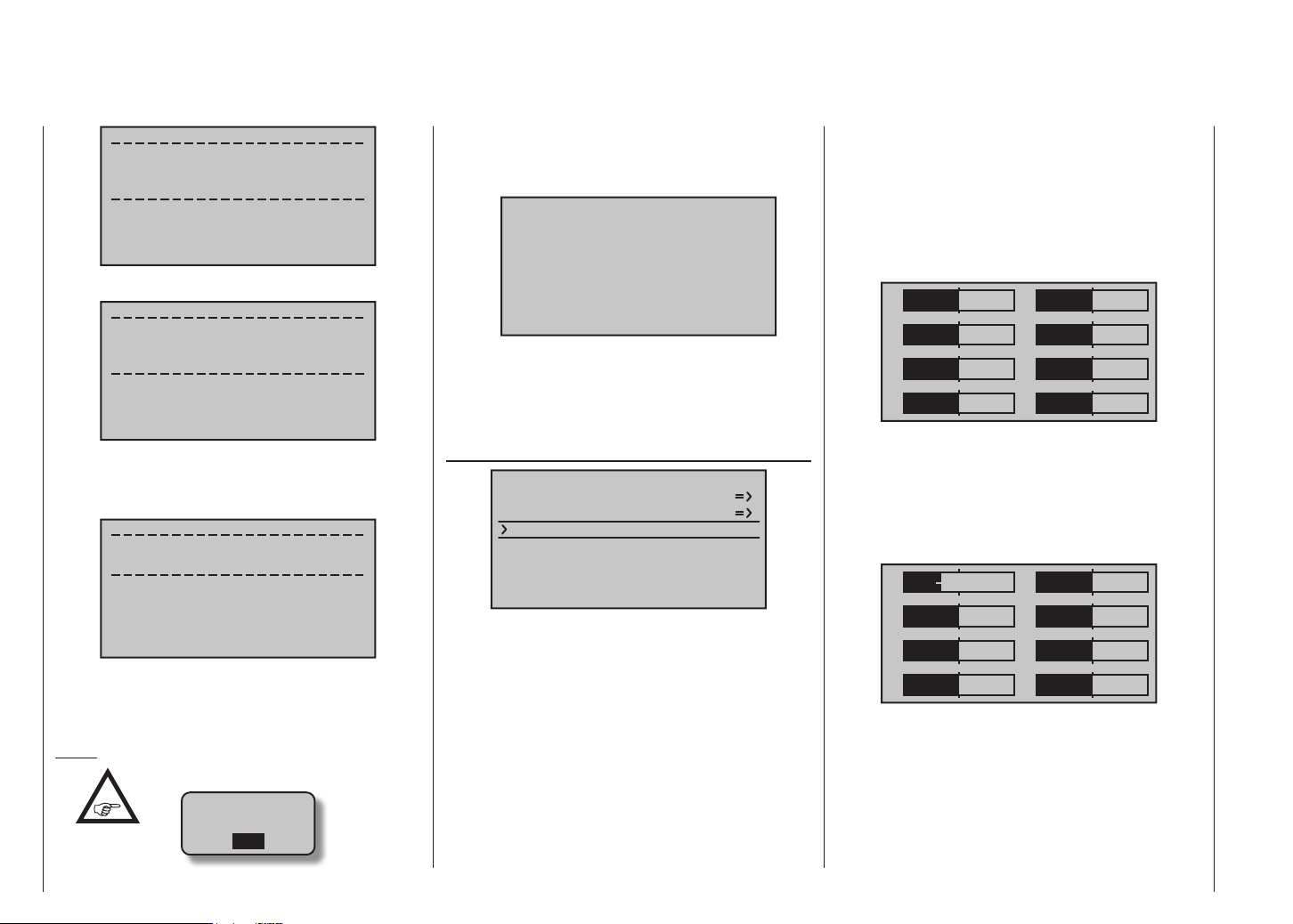
Boot Download
Success!!!
Please Wait....
… this display:
Firmware
Downloading...
Progress 023/123
The loading process is complete when the counter to
the left of “/” reaches “Data quantity” to the right of it, and
this message appears:
Firmware Upgrade
success!!!
… then there is no memory card in the card slot, or
the card cannot be read.
• If the Select window is empty …
FILE LIST
… then the transmitter cannot find a suitable firmware file on the SD card in the slot. If this should happen, check the contents of the “Firmware” folder on
the SD card by inserting it into a PC or laptop.
STICK CALIBRATION
HIDDEN MODE
VOICE
FIRMWARE UPDATE
STICK CALI.
to the “Servo display” menu with, for example, a simul-
taneous brief press of the buttons of the left-hand
touch-key, but WITHOUT moving the trims, or carrying
out any other programming procedures.
If all four of your primary stick functions are still set to
self-centring action, the screen display should look like
this:
1
3
5
7
0%
0%
0%
0%
2
4
6
8
0%
0%
0%
0%
Otherwise the bar and % figure for the non self-centring
stick function - usually that of the throttle / brake or
throttle / collective pitch stick “Ch 1” - will correspond to
the stick’s current position. For example, if the throttle /
brake stick is at the “quarter-throttle” position, then the
screen will look like this:
1
–50%
2
0%
After a few seconds the message disappears, and the
transmitter re-starts. The system is now ready for use
again.
Notes:
•
If this warning message appears …
SD-CARD
INSERT
OK
Description of transmitter
28
If you suspect that the centre point of your self-centring
sticks (transmitter controls 1 … 4) does not correspond
exactly to 0% travel of the transmitter control, you can
check and - if necessary - correct it using the following
procedure:
Move to the “Model select” menu and set up a free
model memory, as described on page 66. It makes no
difference whether you select a fixed-wing or helicopter
model type.
Wait for the usual on-screen messages which appear
in the base display after switching models, then move
3
5
7
0%
0%
0%
4
6
8
0%
0%
0%
Now move each of the two primary sticks to each of the
four possible end-points in turn, but without exerting
pressure at the end-points. At each of the end-points eight in total - the screen should show exactly -100% or
+100%, depending on the side of centre. For example,
if transmitter control 2 is at its right-hand end-point, and
the three other stick functions are all at centre, then your
Page 29
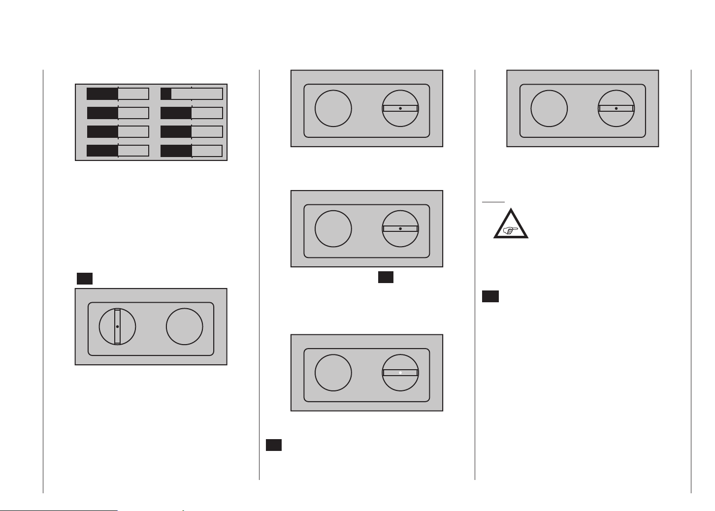
transmitter’s screen display should look like this:
1
3
5
0%
0%
0%
2
4
6
–100%
0%
0%
STICK CALIBRATION
0%
STICK CALIBRATION
0%
7
0%
8
0%
If this checking procedure shows a result of up to four
times 0% and eight times 100% - depending on the
number of your transmitter’s self-centring stick functions
- then the transmitter’s sticks are perfectly calibrated.
You can conclude the procedure and - if you wish erase the model memory you have just created.
If this is not the case, move to the “Stick calibration”
line of the “HIDDEN MODE” menu as described at the
start of the preceding double page, and briefly press the
central SET button of the right-hand touch-key:
STICK CALIBRATION
0%
With the arrow buttons of the right-hand touch-key
you can now select in turn the positions of the four stick
planes to be calibrated, for example, those of the left /
right plane of the right-hand stick:
Move the “left” flashing arrow marker to the left-hand
end-point using the right-hand stick - again without
exerting pressure …
STICK CALIBRATION
+100%
… and briefly press the central SET button of the
right-hand touch-key. In our example this completes the
calibration of the “left-hand” end-point of the right-hand
stick, and the circle in the centre of the stylised stick
plane flashes to confirm this:
STICK CALIBRATION
+100%
Now release the self-centring stick, so that it can take
up its centre position, and again press briefly the central
SET button to calibrate the centre position. The “right”
triangular marker now starts to flash:
Now repeat the calibration procedure for the right-hand
end-point of the right-hand stick. Repeat the procedure
for the other stick planes.
Notes:
•
If you make a mistake in the calibration
process, simply repeat the appropriate
step.
• Within any one stick plane each of the three calibration positions can be selected directly using the arrow buttons of the left or right-hand touch-key.
Conclude the procedure by briefly pressing the central
ESC button of the left-hand touch-key, then quit the
“Stick calibration” sub-menu.
Description of transmitter
29
Page 30
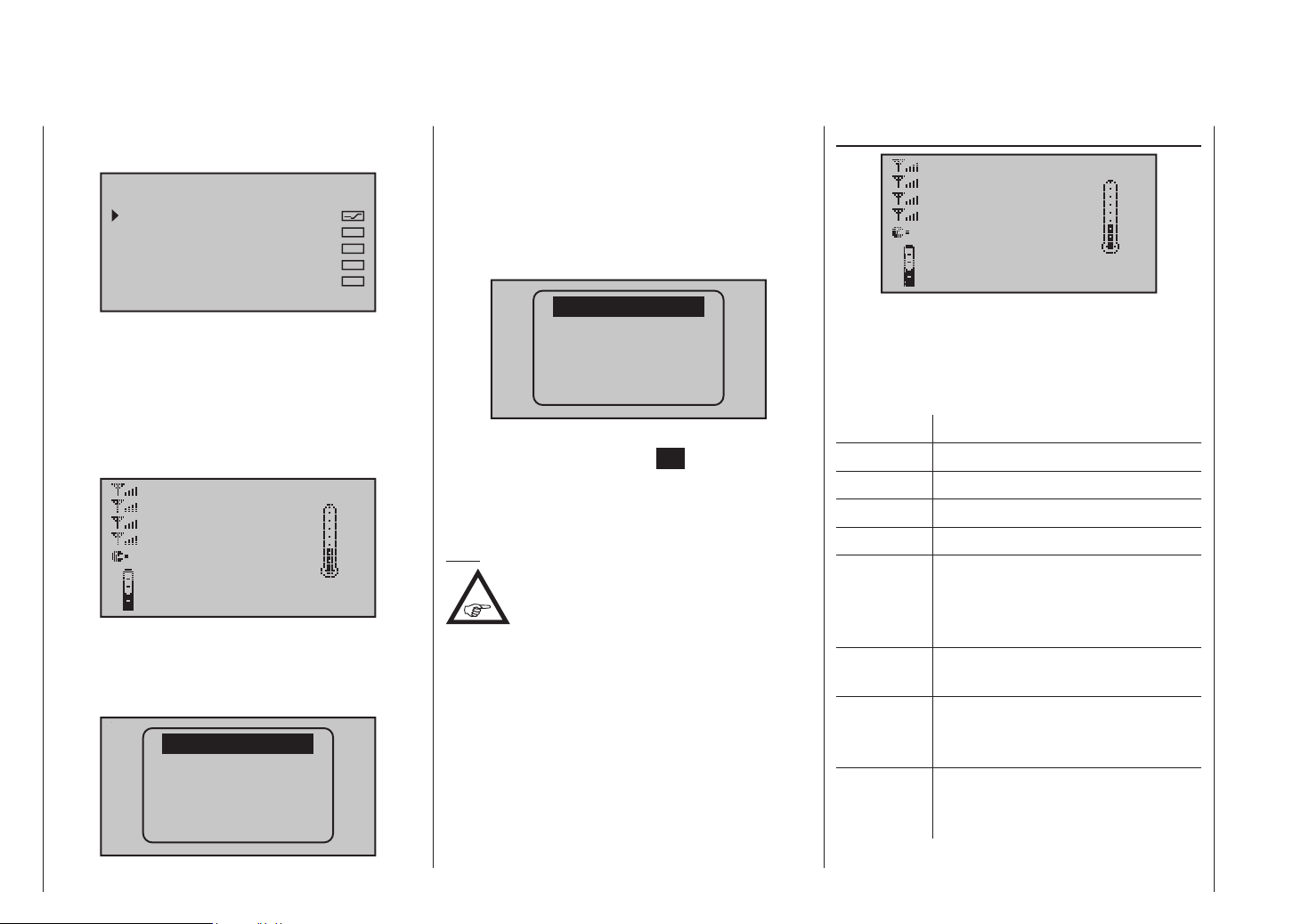
Telemetry data display
As described on page 150, as part of the “SENSOR
SELECT” sub-menu of the “Telemetry” menu …
SENSOR SELECT
RECEIVER
GENERAL MODULE
ELECTRIC AIR.MOD
VARIO MODULE
GPS
… the graphic displays of one or more sensors can be
activated.
The “Receiver” display, and other graphic displays
activated in accordance with your choice of sensors, is
accessed from the transmitter’s base display by briefly
pressing the or button of the left or right-hand
touch-key:
RX–S QUA: 100%
RX–S ST : 100%
RX–dBm: –33dBm
TX–dBm: – 33dBm
L–PACK: 10ms
RX–VOLT:4.8V TMP
R–LOW V:4.6V +22°C
You can switch between the displays for the sensors
activated in the “SELECT SENSOR” sub-menu of the
“Telemetry” menu by briefly pressing one of the arrow
buttons of the left or right-hand touch-key …
RECEIVER
GENERAL
ELECT. AIR
VARIO
GPS
… and selecting the line for the desired sensor after
superimposing the Select window by pressing one of
the two buttons. If no sensor is currently active, all
the other displays / sensors described in the following
section are suppressed from the Select list, with the
exception of the “RECEIVER” display, which is described
in the next column:
RECEIVER
If you wish, you can confirm your choice immediately
after this by pressing the central SET button of the
right-hand touch-key; alternatively you can simply wait
until, after a brief interval, the selected display appears
automatically.
Note:
The displays are described below in the
sequence which occurs when you press the
button.
For more information on these modules please see the
Appendix, or refer to the product on the Internet at www.
graupner.de/en.
RECEIVER
RX–S QUA: 100%
RX–S ST : 100%
RX–dBm: –33dBm
TX–dBm: – 33dBm
L–PACK: 10ms
RX–VOLT:4.8V TMP
R–LOW V:4.6V +22°C
This screen displays the data which can also be viewed
in the “RX DATAVIEW” screen of the telemetry menu
“SETTING & DATA VIEW” (see page 138), but in
graphic form.
The meanings are as follows:
Value Explanation
RX-S QUA Signal quality in %
RX-S STR Signal strength in %
RX-dBm Receive performance in dBm
TX-dBm Transmit power in dBm
L-PACK Shows the longest period in ms
in which data packets were lost in
transmission from transmitter to
receiver
RX-VOLT Actual receiver operating voltage in
Volts
R-LOW V Lowest receiver operating voltage in
Volts since the last time it was switched
on
TMP The thermometer indicates the
receiver’s current operating
temperature
Description of transmitter - Telemetry data display
30
Page 31

GENERAL MODUL
0ml
RECEIVER
GENERAL
ELECT. AIR
BAT1
0.0V
T1 0°C
BAT2
0.0V T2 0°C
BAT1
0.0V
T1 0°C
BAT2
0.0V T2 0°C
This display visualises the data from a General-Engine
module, Order No. 33610, or a General-Air module,
Order No. 33611, connected to the receiver. For more
information on these modules please see the Appendix,
or refer to the product on the Internet at www.graupner.
de/en.
Depending on the sensors connected to the modules,
the following data may be generated constantly on the
screen:
The actual voltage of up to two batteries (BAT1 and
BAT2); the measurement results from up to two temperature sensors (T1 and T2); also a fluid level indicator for
VARIO
GPS
E FUEL F
E FUEL F
CELL.V
1:0.00
2:0.00
3:0.00
4:0.00
5:0.00
6:0.00
0
ALT
0m
0m1
0m3
POWER
0.0V
0.0A
0
the fueltank.
At the right-hand margin you will see an alternating
display either of the actual cell voltages of a battery
pack (up to six cells), or the current altitude relative to
the pilot’s location, climb / descent in m/1 s and m/3 s,
the actual current in Ampere and the actual voltage of
the battery connected to the sensor.
The meanings are as follows:
Value Explanation
BAT1 / BAT2 Battery 1 / Battery 2
FUEL Fuel level / Fueltank indicator
E / F Empty / full
T1 / T2 Temperature of sensor 1 / sensor 2
CELL V Cell voltage of cell 1 … max. 6
ALT Current altitude
0m1 m/1 sec climb / descent
0m3 m/3 sec climb / descent
0.0V Actual voltage of drive battery
0.0A Actual current in Ampere
Battery and consumption display
0.0V
0.0A
0mAh
This display visualises the actual voltage, the actual
current drain and the consumed capacity of any battery connected to the “Battery 1” socket of the General
Engine module (Order No. 33610) or the General Air
module (Order No. 33611), or the consumed fuel in ml.
SENSOR 1
SENSOR 1
0.0V
0°C
This display visualises the actual voltage and temperature measured by a temperature / voltage sensor, Order
No. 33612 or 33613, connected to the “T(EMP)1” socket
of the General Engine module (Order No. 33610) or the
General Air module (Order No. 33611).
SENSOR 2
SENSOR 2
0.0V
0°C
This display visualises the actual voltage and temperature measured by a temperature / voltage sensor, Order
No. 33612 or 33613, connected to the “T(EMP)2” socket
of the General Engine module (Order No. 33610) or the
General Air module (Order No. 33611).
Description of transmitter - Telemetry data display
31
Page 32

Rev-count sensor
0
0.0
0
rpm
0
This display visualises the rotational speed measured by
a rev-count sensor, Order No. 33615 or 33616, connected to the General Engine module (Order No. 33610) or
the General Air module (Order No. 33611).
Note:
For correct display of rotational speed you
must first set the appropriate number of
blades by accessing the Telemetry menu for
the sensor.
Vario
0
m
m
s
This display visualises the data for altitude in m relative
to the location or launch point, and the actual climb /
sink rate in m/s, generated by the integral vario in the
General Engine module (Order No. 33610) or the General Air module (Order No. 33611).
ELECTRIC AIR MODUL
RECEIVER
GENERAL
ELECT. AIR
0.0V 0A
ALT 0m
BAT1 0m/1s
0.0V 0m/3s
BAT2
0.0V T2 0°C
0.0V 0A
ALT 0m
BAT1 0m/1s
0.0V 0m/3s
BAT2
0.0V T2 0°C
This display visualises the data from an Electric-Air
module, Order No. 33620, connected to the receiver.
For more information on this module please see the
Appendix, or refer to the product on the Internet at www.
graupner.de/en.
Depending on the sensors connected to the modules,
the following data may be generated constantly on the
screen:
The actual voltage of up to two batteries (BAT1 and
BAT2); the measurement results from up to two temperature sensors (T1 and T2); the current altitude relative
to the pilot’s location, the model’s climb / descent rate in
VARIO
GPS
T1 0°C
T1 0°C
0
1L0.00
2L0.00
3L0.00
4L0.00
5L0.00
6L0.00
7L0.00
0
1H0.00
2H0.00
3H0.00
4H0.00
5H0.00
6H0.00
7H0.00
m/1 s and m/3 s, and - in the centre of the screen - the
actual current drawn from a power source.
At the right-hand margin you will see an alternating
display of the actual cell voltages of the battery packs
(up to seven cells) connected to balancer sockets 1 (L)
or 2 (H).
The meanings are as follows:
Value Value
V Actual voltage
A Actual current
BAT1 / BAT2 Battery 1 / Battery 2
ALT Current altitude
m/1s m/1 sec climb / descent
m/3s m/3 sec climb / descent
T1 / T2 Temperature at sensor 1 / 2
L / H Cell voltage of cell 1 … max. 14
L = balancer socket 1
H = balancer socket 2
BAT 1
0.0V
0.0A
0mAh
This display visualises the actual voltage, the actual
current drain and the consumed capacity of any battery
connected to the “Battery 1” socket of the Electric Air
module (Order No. 33620).
Description of transmitter - Telemetry data display
32
Page 33

SENSOR 1
0.0
0
0.0
0
SENSOR 1
0.0V
0°C
This display visualises the actual voltage and temperature measured by a temperature / voltage sensor, Order
No. 33612 or 33613, connected to the “T(EMP)1” socket
of the Electric Air module (Order No. 33620).
SENSOR 2
to the location or launch point, and the actual climb /
sink rate in m/s, generated by the integral vario in the
Electric Air module (Order No. 33620).
VARIO
RECEIVER
GENERAL
ELECT. AIR
m/1s
0.0
VARIO
GPS
H
RXSQ
0
MIN The pre-set altitude limit below the
launch point; below this altitude the
transmitter emits audible warning
signals
m/1s m/1 sec climb / descent
m/3s m/3 sec climb / descent
m/10s m/10 sec climb / descent
H High
L Low
Vario
SENSOR 2
0.0V
0°C
This display visualises the actual voltage and temperature measured by a temperature / voltage sensor, Order
No. 33612 or 33613, connected to the “T(EMP)2” socket
of the Electric Air module (Order No. 33620).
Vario
m
m
s
This display visualises the data for altitude in m relative
m/3s
0.0
m/10s
0.0
This display visualises the data from a Vario module,
Order No. 33601, connected to the receiver.
The meanings are as follows:
Value Explanation
ALT Current altitude
RXSQ Signal quality of the signal picked up by
the receiver in %
MAX The pre-set altitude limit relative to
the launch point; above this altitude
the transmitter emits audible warning
signals
ALT
0
L
MAX
0m
MIN
0m
m
m
s
This display visualises the data for altitude in m relative
to the location or launch point, and the actual climb /
sink rate in m/s, generated by a Vario module (Order No.
33601) connected to the Telemetry socket of a receiver.
GPS
RECEIVER
GENERAL
ELECT. AIR
Description of transmitter - Telemetry data display
VARIO
GPS
33
Page 34

N
0.0
0
W
This display visualises the data delivered by a GPS
module with integral vario, Order No. 33600, connected
to the receiver.
In addition to the model’s current positional data and
speed, shown in the centre of the screen, the display
also includes the current altitude in relation to the launch
point and the model’s climb / sink rate in m/1 s, m/3 s
and m/10 s. The current reception quality and the model’s distance from the launch point are also displayed.
The meanings are as follows:
Value Explanation
W / N / E / S West / North / East / South
Kmh Speed
RXSQ Signal quality of downlink channel
DIS Distance
ALT Current altitude relative to launch point
m/1s m/1 sec climb / descent
m/3s m/3 sec climb / descent
0
Kmh
S
RXSQ 0
DIS 0m
ALT 0m
E
0.0m/1s
N 0°00.0000
E 0°00.0000
0m/3s
Vario
m
m
s
This display visualises the data for altitude in m relative
to the location or launch point, and the actual climb /
sink rate in m/s, generated by the integral vario in the
GPS / Vario module (Order No. 33600).
GPS
N
0
W
Kmh
This display visualises the data delivered by a GPS
module with integral vario, Order No. 33600, connected
to the receiver.
The meanings are as follows:
Value Explanation
W / N / E / S West / North / East / South
km/h Speed
DIS Horizontal distance in m
m/s Climb / descent in m/s
ALT Altitude relative to launch point in m
E
S
0.0
0
0
0
km/h
DIS
m
m/s
ALT
m
Description of transmitter - Telemetry data display
34
Page 35

For your notes
35
Page 36

On-screen warnings
Warnings
“Binding not present”
No receiver is bound to the
BIND N/A
OK
RF ON/OFF?
ON
OFF
battery
needs
charging
fail safe
setup
t.b.d
MISSING
IMPORT
DATA
OK
currently active model memory. A brief touch of the SET
button takes you directly to the
corresponding option.
Do you want the RF signal to
be “ON” or “OFF?
Battery must be charged
Operating voltage too low
Fail-Safe not yet set up
No suitable voice files found
on the memory card
CAN‘T
RECEIVE
DATA
OK
no
student
signal
SD-CARD
INSERT
OK
No bound receiver in range.
No connection between
Teacher and Pupil transmitters
No SD or SDHC memory card
in the card slot, or card cannot
be read.
TRAINER
Wireless Link
INHACT
A “wireless Trainer connection” was used before the
transmitter was last switched off; do you wish that connection to be continued (ACT), or switched OFF (INH)?
On-screen function fields
SEL, STO, SYM, ASY, ,
The bottom line of the screen displays function fields
which vary according to the menu selected.
SEL STO SYM ASY
The function fields are activated by touching the SET
button.
Function fields
• SEL select
• STO store (e. g. transmitter control position)
• SYM adjust values symmetrically
• ASY adjust values asymmetrically
Switch symbol field
•
(assigning switches of all kinds)
Switch to second page (next menu)
•
within a menu
throttle
too
high !
The throttle stick (or helicopter
limiter) is set too far in the
direction of full-throttle
Request to switch off the RF
RF
MUST BE
OFF
OK
section
(voice files can only be loaded
with the RF section switched
off)
Description of transmitter - On-screen warnings and function fields
36
Page 37

Position display
Rotary proportional controls CTRL 7 and 8
As soon as you operate one of the two rotary controls
CTRL 7 + 8 on the centre console, a small symbol appears to the right of the two vertical position indicators:
At the same time the position display of the two central
vertical bars switches for the duration of the actuation
from the display of the current trim position to the current position of the rotary controls CTRL 7 + 8.
As you would expect, the left-hand bar represents the
position of the left-hand rotary control CTRL 7, and the
right-hand bar reflects the position of CTRL 8 (however,
both horizontal bars continue to show the current position of the corresponding transmitter stick trim levers):
0:00
0:00
HoTT
#01
3:33h
stop
flt
5.2V
M
Input lock
To prevent programming errors, it is possible to lock
the touch-keys, and with them access to all the set-up
options, from the base display of the mx-16 HoTT
transmitter by touching the ESC and SET buttons for
about two seconds. This is indicated by an inverted key
symbol at the centre point of the trim bars:
stop
#01
5.2V
3:33h
The lock is immediately active, but the control system
remains ready for use.
Touching the ESC and SET buttons again for about two
seconds disengages the lock: the next time you switch
the transmitter on, the lock is also disengaged.
flt
M
0:00
0:00
HoTT
5.5V
About two seconds after you cease operating one of
the two rotary controls, the screen reverts to a display
of the current position of the four trim levers for the two
dual-axis stick units.
Description of transmitter - Position display and Input lock
37
Page 38

battery
needs
charging
Using the transmitter for the first time
Preliminary notes regarding the mx-16 HoTT transmitter
For more information please visit our Internet site at www.graupner.de/en
Preliminary notes
In theory the Graupner|SJ HoTT system permits the
simultaneous operation of more than 200 models.
However, in practice the mixed operation of different
technical systems in the 2.4 GHz ISM band - as required
by the approval regulations - reduces this number considerably. Generally, however, it will always be possible
to operate even more models simultaneously on the 2.4
GHz band than on the 35 / 40 MHz frequency bands
which we have used to date. However, the actual limiting
factor - as it has always been - is likely to remain the
size of the (air-) space available. The simple fact that
no frequency control procedure is necessary - a great
convenience in itself - equates to an enormous gain in
safety, especially at flying sites where groups of pilots
may be distributed over a large area, with nobody in
overall control.
Battery charged?
When you take receipt of your transmitter, the battery
will be in the discharged state, so you must first charge
it as described on page 14. If you do not do this, the
battery will soon fall below the pre-set threshold voltage,
and you will see and hear a warning signal to remind
you to recharge it. The threshold
voltage can be adjusted in the
“Battery warning threshold” line
of the “Basic settings” menu;
see page 134.
Switching the transmitter on
When you switch the transmitter on, the following display
appears in the centre of the transmitter screen for about
two seconds:
Using the transmitter for the first time
38
Within this period you can switch off the RF signal if
required by moving the black field to the right using the
or arrows of the right-hand touch-key; when you
do this, ON should appear normal, and OFF in inverse
form (black background).
You can now switch the RF module off by briefly pressing the central SET button of the right-hand touch-key.
Until this point the central LED glowed blue, but it now
changes to red, and at the same time the screen switches to the transmitter’s base display:
The symbol combination means that the currently active model memory is already “bound” to a Graupner|SJ
HoTT receiver, but there is currently no connection with
this receiver. (In our example we - of course - switched
off the RF signal!)
In contrast, if you switch the transmitter on without
switching off the RF signal, the central LED glows an
intense blue, and the symbolic transmitter mast flashes.
At the same time the transmitter emits an audible warning until a connection is made with the corresponding
receiver. Once this connection exists, a field strength
#01
0:33h
RF ON/OFF?
ON
RF ON/OFF?
ON OFF
5.2V
OFF
stop
flt
M
0:00
0:00
HoTT
0.0V
indicator appears instead of the “x” at the base of the
symbolic aerial, for example , and the visual and
audible warnings cease.
At the right of the same line a display in the same format
appears when a telemetry connection is made, showing
the strength of the telemetry signal picked up from the
receiver (>M
receiver power supply.
However, if the symbol combination
the central LED glows a constant red, the currently
active model memory is not “bound” to any receiver.
Low-voltage warning
If the transmitter voltage falls below a particular value,
a visual and audible low-voltage warning is generated.
The default value is 4.7 V, but this can be varied in the
“Basic settings” menu (page 134).
Important notes:
•
If you wish to operate the RC system in France,
you MUST first set the Country setting on the
transmitter to “FRANCE” mode; see page 135.
IT IS PROHIBITED to use the system IN FRANCE
using the Universal / EUROPE mode!
• You can operate up to eight servos using the
mx-16 HoTT transmitter and the receiver supplied in the set, which is already bound to the
transmitter.
However, in the interest of maximum possible flexibility, control channels 5 … 8 are not assigned to transmitter controls by default; this
) together with the actual voltage of the
appears, and
The transmitter included in the set is
prepared at the factory with the correct settings for most European countries (except France).
Page 39

also helps to eliminate the danger of inadvertently using them incorrectly. This means that any
servos connected to these channels will simply
“stay put” at their centre position until a transmitter control is assigned to the channel in question. For the same reason virtually all the mixers
are inactive by default. For more details of this
please refer to page 86 (fixed-wing model) or 88
(helicopter).
• The basic procedure for programming a new
model memory can be found on page 66, and
in the programming examples starting on page
164.
• When switching on, binding or setting up the radio control system, please ensure at all times
that the transmitter aerial is an adequate distance
from the receiver aerials. If the transmitter aerial
is too close to the receiver aerials, the receiver
will be swamped, and the red LED on the receiver will begin to glow. At the same time the downlink channel will stop working. As a result the
field strength bars on the transmitter screen are
replaced by “x”, and the receiver battery voltage
is displayed as 0.0 V. At the same time the radio
control system switches to Fail-Safe mode, see
page 136, i.e. the servos remain fixed in their
current position for as long as reception is not
possible, and until a new, valid signal is picked
up.
If this should happen, simply increase the distance between transmitter and receiver until the
displays revert to “normal”.
WARNING:
Never switch off the transmitter while the
model is in operation! However, if this
does happen, keep calm and wait until
the transmitter display goes off and the transmitter
has shut down completely. This takes at least three
seconds. Don’t switch the transmitter back on until
then. Otherwise, there is a danger that the transmitter will get “hung up” immediately after being
switched back on, causing you to lose control of the
model. Then it will not be possible to restart the
transmitter until you have switched it off again and
have carried out the described procedure correctly.
Using the transmitter for the first time
39
Page 40

Downloading and updating the transmitter firmware
The transmitter firmware can be updated at the owner’s
risk using either of two methods:
• As described under “FIRMWARE UPDATE / Changing the screen language” in the section entitled
“Hidden mode” on page 27.
• As described in the next section, using the five-pin
mini-USB port on the back of the transmitter, in
conjunction with a PC or laptop running Windows XP,
Vista or 7.
Downloading a software package
Current software and information can be found in the
Download section for the corresponding product at www.
graupner.de/en.
Note:
Once you have registered your transmitter at
https://www.graupner.de/en/service/
product_registration.aspx you will automatically be informed of new updates by e-mail as they
become available.
The easiest method of accessing the “corresponding”
product page, as mentioned above, is to enter www.
graupner.de/en in the address line of your Internet
browser, and then press the ENTER button of your PC
or laptop:
This takes you to the home page of the Graupner company website, where you will find an input field at top
right below the title “Suchen / Search”:
Place the mouse pointer in this field and then enter a
search term, for example, the article number printed on
the type placard on the back of your transmitter:
Press the ENTER key of the PC or laptop once more,
and the page you require will appear:
If you now use the mouse to move your browser’s lateral
scroll bar down a little, you will see the tabs “Features”,
“Replacement parts”, “Accessories” and “Downloads”.
Click on the “Download” tab to move to the Download
area:
Downloading and updating the transmitter firmware
40
Page 41

Select the required file(s) and start the downloading
process by double-clicking on “Download” below the
selected file.
Selecting “HoTT-Software VX” downloads the file
“HoTT_Software_VX.zip”. This compressed file contains
all the files required to update the transmitter, HoTT
receiver, sensors, etc.
Please note: at the time of revising this manual the
current version of the program package is version “4” “HoTT-Software V4”.
If the last update you loaded is version “V3” or older,
all components of the radio control system MUST be
updated to version “V4”. If you ignore this, you may
encounter malfunctions in individual components. The
same applies to future download packages “V5” or
higher.
If individual firmware files change within a version “VX”,
all you need to do is install the new, later firmware version for the corresponding product. The date of creation
of the download file initially tells you whether firmware
updates are present, and the version numbers of the
relevant firmware files also change.
Now save the file in a folder of your choice, and unpack
it using a suitable program.
If a transmitter update does not function as described
below, please continue reading the section entitled
“Restoring the transmitter firmware” on page 44.
Updating the mx-16 HoTT software
To update the transmitter software you only need the
USB lead supplied as standard with the USB interface,
Order No. 7168.6. This can be plugged directly into the
five-pin mini-USB socket on the back of the transmitter.
Important notes:
•
ware is compatible. That is why the programs
required to update all the HoTT components and
files are grouped in a single file, which is currently named HoTT_Software_V4.zip”.
Please note that reliable communication between your system’s HoTT components is only guaranteed if the firm-
• It is essential to check the state of charge of your
transmitter battery before you carry out any update. For safety’s sake recharge it and back up
all occupied model memories, so that you can restore them if anything goes wrong.
• The connection between the transmitter and the
PC or laptop must not be interrupted during the
update process, so please ensure that there is reliable contact between the transmitter and the
computer.
1. Unpacking the program package
Unpack the file “HoTT_Software_VX.zip” into a convenient folder. For example, you might name the folder “HoTT_Software_VX”, the “X” standing for the current version number.
2. Installing the driver
If you have not already done so, install the driver software which is included in the program package in the
“USB driver” folder; this is necessary in order to use
the transmitter’s integral USB port.
Start the driver installation by double-clicking on the
corresponding file, and follow the instructions. After a successful installation the computer will need to
be restarted. Note that the driver only has to be installed once.
3. Connecting the transmitter to the PC
Connect the USB lead to the PC or laptop and the
five-pin mini-USB socket on the back of the transmitter, with the transmitter switched off. Check that the
USB lead is making solid contact.
Downloading and updating the transmitter firmware
41
Page 42

4. Updating the mx-16 HoTT transmitter software
Start the program “Firmware_Upgrade_grStudio_VerX.X.exe”, which is now stored in the folder you have
just named “HoTT_Software_VX” (or similar). (Note:
version 1.9, which is current at the time this manual went to press, starts without being installed beforehand.):
Open the “Controller Menu” and click on “Port Select”
in the “Upgrade” folder. Alternatively select the “Port
Select” entry under “Menu”:
Now select the correct COM port in the “Port select”
Downloading and updating the transmitter firmware
42
window, i.e. the port to which the USB interface is
connected. You can recognise this by the name “Silicon Labs CP210x USB to UART Bridge” in the “Device Name” column. In the screen-shot above this
would be the “COM 3” port.
Now call up the “Firmware Upgrade” option in the
“Transmitter” folder under “Controller Menu”. Alternatively select the “Firmware Upgrade” entry under
“Menu”:
When you have called up the program, you will see
the number “1” flashing red in the numeric row 1 … 7
at the top of the window, indicating that the program
is currently operating at “[Process Step] 1”.
In each case the meaning of the currently flashing
step is indicated immediately below the numeric row:
For example, at Step 1: “Connect USB lead to PC
and transmitter” and “Press File Browse button and
select Update file”, as shown here.
Note:
At any time you can call up an explanation of any step in the form of Quick-Info
by positioning the mouse pointer over a
number.
If you have not already done so, connect your transmitter to the PC or laptop at this point. Now click on
the button marked “File Browse” and select the firmware update file matching your transmitter in the
“Open file” dialogue which now appears; the file suffix will be “bin”.
In the case of the zip file “HoTT_Software_VX” which
you have already downloaded and unpacked, this
will usually be found in the folder “Official Version \
33112_ …_ 33032_mx-xx_mc-32 \ SD card \ Firmware”, and is called “mx-16_1vXXX_German.bin” (or
“… English.bin”). The file appears in the associated
window. At the same time the “2” starts to flash red
instead of the “1”.
The firmware files are encoded in a manner specific to each product, i.e. if you accidentally select a file
which does not match the product (e.g. receiver update file instead of transmitter update file), the popup window “Product code error” appears, and you will
be unable to continue the update process.
Follow the instructions for “[Process Step] 2”. If you
have not already done so, switch the transmitter on
at this point, and then start the transmitter update by
clicking on the “Download Start” button.
Shortly after this you will see a warning that the
transmitter’s RF signal is being disabled: “RF will be
switched OFF.” Before clicking on “Yes” you should
therefore switch the receiving system off if it is currently operating.
Page 43

At this point the actual update process begins, and a
progress bar starts to advance above the constantly changing lines of text. At the same time the flashing red number continues to indicate the current “Process Step”.
You must not interrupt the connection between
the transmitter and the PC during the update process!
The update is finished when the progress bar reaches the right-hand end, and the message “Firmware
Download Success” appears. At the same time the
[Process Steps] display moves on to “7” “Update Process Finish”:
Click on “OK”, then switch the transmitter off and finally disconnect the lead between the transmitter and
the PC or laptop.
If the progress bar fails to advance, or if the update
process terminates before it reaches the 100% mark,
close the program and repeat the update procedure,
i.e. carry out each of the steps described above once
more. If an update fails repeatedly, please read the
following section.
If you accidentally attempt to load a version of the
firmware which is correct, but older than the one currently in the transmitter, the screen will display a corresponding warning:
Unless you really want to load older firmware, click
on “No” with the mouse, and load the correct *.bin file
using the “File Browse” button.
Downloading and updating the transmitter firmware
43
Page 44

Restoring the transmitter’s firmware
„Emergency“ program
Restoring the mx-16 HoTT transmitter software
If a transmitter firmware update should fail, or if the
transmitter software “hangs” (in which case you may not
be able to switch the transmitter off using the “POWER”
switch), then you can restore the earlier firmware using
the “Emergency” program segment.
If you switch the transmitter off, but the screen continues
to be active, then please set the switch to the “POWER=OFF” position, unplug the transmitter battery, wait a
few seconds, then plug it in again - but leave the POWER switch at the “OFF” position!
1. Starting the “Emergency” program
Now move to the “Controller Menu” and select the
“Emergency” entry under the heading “Transmitter”:
Ensure that the transmitter is switched off! Connect
the USB lead to the PC or laptop, and to the USB
socket on the back of the transmitter.
2. Restoring the mx-16 transmitter software
Press the “File Browse” button and search for the
current firmware in the program window which now
opens; as mentioned earlier, you will find this in the
“Official Version \ 33112_…_33032_mx-xx_mc-32 \
SD card \ Firmware” folder of the unpacked “HoTT_
Software_VX” file. The file matching the mx-16
transmitter is called: “mx-16_1vXXX_German.bin” (or
“…English.bin”).
Now press the “Download Start” button to initiate the
update process. Wait for a moment until the status
Restoring the transmitter’s firmware
44
bar starts to advance, and only then switch the transmitter on. Don’t be surprised if the screen comes to
life, but displays no information.
(If the progress bar reaches the right-hand end before the transmitter is switched on, you will have to
click on the “Download Start” button again.)
After you switch the transmitter on, there may well
be a wait lasting a minute before the process actually starts.
The transmitter’s signal melody sounds, the transmitter screen switches itself on with the start display
“mx-16 HoTT”, and the current firmware version is
shown on the screen.
Finally click on “OK”. Switch the transmitter off, and
disconnect the USB lead from the transmitter and the
PC or laptop.
The progress bar indicates that the data transfer process is under way, and the screen displays [Process
Step] “No 4, Firmware downloading …”.
Ensure that the USB lead is making reliable contact,
and do not interrupt the update process.
The firmware transfer is finished when the progress
bar reaches the right-hand end; you will then see the
message “File Transfer Success” to indicate that the
transfer has been successful.
Page 45

For your notes
45
Page 46

Using the receiver for the first time
Preliminary notes regarding the GR-16 receiver
For more information please visit the Internet at www.graupner.de/en.
Receiving system
The mx-16 HoTT radio control set includes a GR-16
2.4 GHz bi-directional receiver which is suitable for
connection to a maximum of eight servos.
If you switch a HoTT receiver on, and “its” transmitter is
switched off or not within range, the red LED on the receiver lights up steadily for about one second, and then
starts to flash slowly. This means that no connection with
a Graupner|SJ HoTT transmitter exists (at this stage).
When the connection is made, the green LED glows
constantly, and the red LED goes out.
In order to create a connection, the Graupner|SJ HoTT
receiver must first be “bound” to “its” model memory in
“its” Graupner|SJ HoTT transmitter; this procedure is
known as “binding”. However, binding is only necessary
once for each receiver / model memory combination
(see pages 80 or 88), and has been carried out at
the factory for model memory 1 using the components
supplied in the set. You therefore only need to carry out
the “binding” process - as described later - with additional receivers, or if you switch to a different model memory. The procedure can also be repeated whenever you
wish - for instance, if you change the transmitter.
Receiver voltage display
Once a telemetry connection exists, the actual voltage
of the receiver power supply is displayed on the righthand side of the transmitter screen.
Temperature warning
If the temperature of the receiver falls below a limit value
set on the receiver (the default is -10°C), or exceeds
the upper warning threshold, which is also set on the
receiver (the default is +55°C), the transmitter generates
a warning in the form of steady beeps at intervals of
Using the receiver for the first time
46
about one second.
Servo connections and polarity
The servo sockets of Graupner|SJ HoTT receivers are
numbered. The connector system is polarised: look for
the small chamfers when inserting the connectors, and
on no account force the plugs into the sockets.
The sockets marked “1+B-” and “6+B-” are intended
for the connection of the battery. It is also possible to
connect the appropriate servos to both these sockets in
parallel with the power supply by using a Y-lead, Order
No. 3936.11.
The power supply voltage is through-connected via all
the numbered sockets. The function of each individual
channel is determined by the transmitter you are using,
rather than by the receiver. Example: the throttle servo
socket is defined by the radio control system, and may
differ according to the make and type.
In the case of Graupner radio control systems the
throttle function is assigned to channels 1 or 6, whereas
it is allocated to channel 3 in the case of Futaba radio
control systems, for example.
Observe the installation notes regarding the receiver,
receiver aerial and servos, which you will find on page
54.
Concluding notes:
•
vious technologies. Please take a little time to be-
Do not connect the battery to these
sockets with reversed polarity, as this is
likely to ruin the receiver and any devices
connected to it.
The much higher servo resolution of the
HoTT system results in a substantially
more direct response compared with pre-
come accustomed to the finer control characteristics
offered by the system!
• If you wish to use a speed controller with integral
BEC* system in parallel with a separate receiver battery, in most cases (depending on the speed controller) the positive terminal (red wire) must be removed
from the three-pin connector, as shown in the diagram. Be sure to read the appropriate notes in the instructions supplied with your speed controller before
doing this.
Carefully raise the central lug of the connector slight-
ly (1), withdraw the red
wire (2) and insulate the
bare contact with tape
to avoid possible short
red
1
2
3
circuits (3).
Reset
To carry out a receiver reset, locate the SET button on
the top of the receiver and hold it pressed in while you
switch the receiver power supply on. Hold the receiver’s
SET button pressed in until the green and the red LED
goes out; this takes about four seconds.
If you carried out the reset with the transmitter switched
off, or with an unbound receiver, the receiver LED will
flash red slowly after a pause lasing about two seconds.
At this point it is immediately possible to initiate a Bind
process at the transmitter.
If the reset is carried out with an already bound receiver,
if the transmitter is switched on, and if the associated
model memory is active, then the LED lights up green
after a short interval to indicate that your transmitter /
receiving system is ready for use once more.
* Battery Elimination Circuit
Page 47

Please note the following:
Resetting the receiver resets ALL the
settings stored in the receiver to the
default settings, with the exception of the
binding information!
If you carry out a RESET by mistake, this means
that you will have to restore all the receiver settings
entered using the Telemetry menu.
On the other hand, a deliberate RESET is particularly useful if you wish to “re-house” a receiver in a
different model, as it represents an easy method of
avoiding the transference of unsuitable settings.
Using the receiver for the first time
47
Page 48

Firmware update of the receiver
Firmware updates for the receiver are carried out using
the telemetry socket on the side of the receiver, in conjunction with a PC running Windows XP, Vista or 7. For
this you require the optional USB interface, No. 7168.6
and the optional adapter lead, Order No. 7168.6S. The
software and files also required for the process can
be found in the Download area for the corresponding
product at www.graupner.de/en.
Note:
Once you have registered your transmitter at
https://www.graupner.de/en/service/
product_registration.aspx you will automatically be informed of new updates by e-mail as they
become available.
Updating the receiver firmware
Important notes:
•
Please note that reliable communication between your system’s HoTT com-
ponents is only guaranteed if the firmware is compatible. That is why the programs
required to update all the HoTT components and
files are grouped in a single file, which is currently named HoTT_Software_V4.zip”.
• It is essential to check the state of charge of your
receiver battery before you carry out any update.
For safety’s sake recharge it before updating.
• The connection between the receiver and the PC
or laptop must not be interrupted during the update process, so please ensure that there is reliable contact between the receiver and the computer.
1. Installing the driver
The driver software for the USB interface, Order No.
7168.6, is identical to the driver software of the interface fitted to the mx-16 transmitter. This means that
the driver only has to be installed once; the procedure is described on page 41.
2. Connecting the receiver to the PC
Connect the USB interface, Order No. 7168.6 to the
receiver socket marked “- + T” using the adapter lead,
Order No. 7168.6S. The connectors are polarised:
look for the small chamfer on the side. The connectors should engage easily; on no account use force.
Adapter lead
Order No. 7168.6A
If a central red wire is present,
cut through it
Caution:
If your adapter lead is of the earlier three-core
type, first cut the central red wire in the adapter
lead, Order No. 7168.6A.
Now connect the USB interface to the PC or laptop
using the USB lead (PC USB / mini-USB) also supplied in the set. When the components are connected
correctly, a red LED on the interface circuit board
should light up red for a few seconds.
The receiver should be left switched off.
3. Firmware update
Start the program “Firmware_Upgrade_grStudio_
Ver-X.X.exe” by double-clicking on it, as described
for updating the transmitter software; see page 42.
(Version 1.9, which is current at the time this manu-
al went to press, starts without being installed beforehand.):
Open the “Controller Menu” and click on “Port Select”
in the “Upgrade” folder. Alternatively select the “Port
Select” entry under “Menu”:
Now select the correct COM port in the “Port select”
window, i.e. the port to which the USB interface is
connected. You can recognise this by the name “Silicon Labs CP210x USB to UART Bridge” in the “Device Name” column. In the screen-shot above this
would be the “COM 3” port.
Now call up the “HoTT Receiver” option in the “Device” folder under “Controller Menu”. Alternatively select the “HoTT Receiver Upgrade” entry under
Updating the receiver firmware
48
Page 49

“Menu”:
When you have called up the program, you will see
the number “1” flashing red in the numeric row 1 … 5
at the top of the window, indicating that the program
is currently operating at “[Process Step] 1”.
In each case the meaning of the currently flashing
step is indicated immediately below the numeric row:
For example, at Step 1: “Connect USB lead to HoTT
receiver” and “Press File Browse button and select
Update file”, as shown here.
Note:
At any time you can call up an explanation of any step in the form of Quick-Info
by positioning the mouse pointer over a
number.
If you have not already done so, connect your receiver to the PC or laptop at this point. Now click on
the button marked “File Browse” and select the firmware update file matching your receiver in the “Open
file” dialogue which now appears; the file suffix will
be “bin”.
In the case of the zip file “HoTT_Software_VX” which
you have already downloaded and unpacked, this
will usually be found in the folder whose name starts
with the Order Number of the receiver to be updated. If your receiver is the GR-16 which is supplied in the set as standard, this would be the folder
“33508_8CH_RX”. The file appears in the associated
window. At the same time the “2” starts to flash red:
Note:
The firmware files are encoded in a
manner specific to each product, i.e. if
you accidentally select a file which does
not match the product (e.g. transmitter update file
instead of receiver update file), the pop-up window
“Product code error” appears, and you will be unable
to continue the update process.
Follow the instructions for “[Process Step] 2”. With
the receiver still switched off, click on the “Download
Start” button in the “HoTT Receiver Upgrade” window.
(The display changes to “[Process Step] 3”.) Wait until the progress bar starts to advance; this may take
several seconds, depending on your computer.
Only at this point should you switch the receiver on
with the SET button pressed in. After a few seconds
“Line 3” appears in the column “No” of the Status display, with the message: “Found target device …”. Release the button at this point. The actual firmware
update process now starts automatically: “11, Start
Firmware upgrade…”.
If the device is not detected, a pop-up window appears with the message “Target device ID not found”.
If this should happen, check your update arrangements and try again:
In the Status display the progress of the firmware update is indicated by the progress bar.
During the update process the green and the red
LED on the receiver glows a constant green and red.
You must not interrupt the connection between
the transmitter and the PC during the update process!
The update is finished when the progress bar reaches the right-hand end, and the message “12, Complete !!” appears in the bottom line of the Status display. At the same time the [Process Steps] display
moves on to “5”.
Updating the receiver firmware
49
Page 50

When the update is completed, the green LED goes
out, and the red LED starts to flash.
If the process terminates before the 100% mark is
reached, switch the receiver power supply off and repeat the update procedure, i.e. carry out each of the
steps described above once more.
If you accidentally attempt to load a version of the
firmware which is correct, but older than the one currently in the receiver, the screen will display a corresponding warning:
Unless you really want to load older firmware, click
on “No” with the mouse, and load the correct *.bin file
using the “File Browse” button.
Finally you MUST initialise the receiver, i.e. reset
it to the factory default settings.
ing on its own. At this point you can release the SET
button.
Switch the transmitter on again, and wait until RF
transmission is active: about two or three seconds after this the green LED of the bound receiver will glow
constantly. If you have not yet bound the receiver to
the transmitter, you can now do so as described on
pages 80 and 88.
Important note:
With the exception of the binding infor-
mation, all the receiver’s previously
programmed settings are now reset to
the default values. You must therefore enter the
data again if necessary; see the section entitled
“Reset” on page 46.
If you wish to “save” the data, you should run the
program “Receiver Setup” before updating the receiver. This will spare you the trouble of re-programming the receiver under the “Telemetry”
menu.
This is accomplished by switching the receiver off
and removing the interface lead.
4. Initialising the receiver
In the interests of safety you should now re-initialise the receiver before re-using it. The screen-shot
shown above indicates this:
Hold the SET button on the receiver pressed in while
you switch the receiver on. The red and green LEDs
flash four times, followed by a pause lasting about
two seconds. At this point the red LED starts flash-
Updating the receiver firmware
50
Page 51

For your notes
51
Page 52

Backing up receiver settings
The “Receiver Setup” segment of the program “Firm-
ware_Upgrade_grStudio” can be used to save all the
data programmed in the receiver in a file on your computer, so that you can transfer the data set back into the
receiver in an emergency; this eliminates the need to
re-program the receiver using the “Telemetry” menu, as
would otherwise be necessary.
We recommend that you call up the “Receiver Setup” program from the “Firmware_Upgrade_grStudio”
program. Alternatively you can start the application
directly. You will find the file “Receiver_Setup.exe” in the
“Graupner_PC-Software” folder.
Note:
If you call up “Receiver Setup” from the
Firmware_Upgrade program, ensure that the
sub-program “Receiver_Setup.exe” is located
in the same folder as the “Firmware_Upgrade_grStudio”
program; see the screen-shot above!
For this program you need the USB interface, Order No.
7168.6, and the interface lead, Order No. 7168.S, sup-
plied in the mx-16 radio control set, Order No. 33116.
Backing up receiver settings
1. Connecting the receiver to the PC
With the receiver switched off, connect the USB interface, Order No. 7168.6, to the socket marked “-+T”
on the receiver using the adapter lead, Order No.
7168.6S.
Backing up receiver settings
52
The connector system is polarised: note the small
chamfers on the edges. Do not use force under any
circumstances; the plugs should engage easily.
Adapter lead
Order No. 7168.6A
If a central red wire is present,
cut through it
Caution:
If you are using the - earlier - adapter
lead, Order No. 7168.6A, and this is
fitted with a three-core lead, cut
through the central red wire of the adapter lead
before using it.
Now connect the USB interface to the PC or laptop
using the USB lead supplied in the set (PC-USB / mini-USB). If connected correctly, a red LED on the interface circuit board should light up.
The receiver should be left switched off at this point.
2. Receiver Setup: selecting the port
Start the program “Firmware_Upgrade_grStudio_
Ver-X.X.exe” by double-clicking on it, as described for
updating the transmitter software (see page 42).
(Version 1.9, which is current at the time this manual went to press, starts without being installed beforehand.)
Open the “Controller Menu” and click on “Receiver
Setup” in the “Upgrade / Link” folder. Alternatively select the “Receiver Setup” entry under “Menu”.
A program window now appears, in which you should
start by setting the “correct” COM port for the USB interface, Order No. 7168.6. If you are not sure of this,
check the COM port in the “Port select” window in
the “Controller Menu” (see earlier), and note the Com
port number at the entry “Silicon Labs CP210x USB
to UART Bridge”. In accordance with the previous update descriptions this would be the port “COM 3”.
(If you select the wrong port, the program will alert
you to the error.)
3. Reading out receiver data
Click on the “Connect” button and wait until the Status bar below it starts to advance:
Locate the SET button on the receiver and hold it
pressed in while you switch it on. After about three
seconds the receiver’s current values will be displayed in the corresponding fields. If the progress bar
is “faster than you are”, and reaches the end before
you have switched the receiver on, the pop-up window shown here appears. In this case repeat the procedure.
Page 53

Important:
The active connection is terminated using
the “Disconnect” button, but you should
only do this if you wish to initialise the receiver directly, as described on page 46 or 50,
and do not wish to overwrite it with a data set you
have already saved.
4. Saving receiver data
The “File Save” button backs up the current servo
configuration on the PC.
The Windows “Save as” dialogue now opens:
First select a folder of your choice in which to save
the file, and enter under “File name” an appropriate and unambiguous name, so that you can easily
find the file again at a later date. The program automatically appends the file suffix “rdf”. The data set is
backed up when you click on the “Save” button. When
the process is complete, this message appears:
Click on “OK” to close the window.
You can now reset the receiver to the default settings,
as mentioned earlier and described on page 46.
Copying a data set to the receiver
You can re-load the backed-up data into the receiver
using the “File Load” function of the Receiver Setup
program.
The first step is to connect the receiver as described
under point 3 “Reading out receiver data”, and click
on the “Connect” button. Assuming that the receiver has
been previously initialised, the program reads out the
default settings.
Now select the desired “rdf” file from the appropriate
folder and click on “OK” in the “File Load” pop-up window. Click on the “Write” button to transfer the data to
the receiver connected to the PC.
When the data transfer is complete, the pop-up window
“Receiver Data Write Success” appears.
Finally you can click on “OK” to confirm the action, then
on the “Disconnect” button to disconnect the Receiver
Setup program from the receiver.
Important notes:
•
The “Receiver Setup” program in-
cludes additional functions which are
currently still in preparation; they must
not be used at present. You can find out about the
latest state of the software in the Download area
for the mx-16 on the Graup ner website.
•
will be updated constantly as soon as new options are available.
A separate manual for the whole “Firmware_Upgrade_grStudio_Ver-X.X” program package is in preparation, and
Backing up receiver settings
53
Page 54

Installation notes
Installing the receiver
Regardless of which Graupner receiving system you are
using, the procedure is always the same:
Please note that the receiver aerials must be
arranged at least 5 cm away from all large
metal parts and leads which are not attached
or connected directly to the receiver. This includes steel
and carbon fibre components, servos, fuel pumps,
cables of all sorts, etc. Ideally the receiver should be
installed in an easily accessible position in the model,
away from all other installed components. Under no
circumstances run servo leads immediately adjacent to
the receiver aerials, far less coil them round it!
Tests have shown that a vertical (upright) position of a
single aerial produces the best results when long approaches are flown with a model. If the receiver features
a diversity aerial system (two aerials), the second aerial
should be deployed at an angle of 90° to the first.
The servo sockets of Graupner receivers are numbered.
The power supply is through-connected via all the numbered sockets, and in principle can be connected to any
of the servo sockets. It is also possible to connect the
power supply via a Y-lead, Order No. 3936.11, in parallel
with a servo.
The function of each individual channel is determined
by the transmitter in use, rather than by the receiver.
However, it is possible to alter the channel assignment
(mapping) by changing the programming in the Telemetry menu. Nevertheless, we recommend that you carry
out this process using the “Receiver output” option; see
page 79 or 87.
The following section contains notes and helpful
ideas on installing radio control components in the
model:
1. Wrap the receiver in foam rubber at least 6 mm thick.
Fix the foam round the receiver using rubber bands,
to protect it from vibration, hard landings and crash
damage.
2. All switches must be installed in a position where
they will not be affected by exhaust gases or vibration. The switch toggle must be free to move over its
full range of travel.
3. Always install servos using the vibration-damping
grommets and tubular metal spacers supplied. The
rubber grommets provide some degree of protection
from mechanical shock and severe vibration. Don’t
over-tighten the servo retaining screws, as this will
compress the grommets and thereby reduce the vibration protection they afford. The system offers good
security and vibration protection for your servos, but
only if the servo retaining screws are fitted and tightened properly. The drawing below shows how to install a servo correctly. The brass spacers should be
pushed into the rubber grommets from the underside.
Servo mounting lug
Retaining screw
Rubber grommet
Tubular brass spacer
chanical linkage can obstruct the servo’s movement.
The sequence in which the servos are connected to the
receiver is dictated by the model type. Please see the
socket assignments listed on pages 63 and 65.
Be sure to read the additional safety notes on pages
4 … 9.
If the receiver is ever switched on when the transmitter
is off, the servos may carry out uncontrolled movements.
You can avoid this by switching the system on in this
order:
Always switch the transmitter on first,
then the receiver.
When switching the system off:
Always switch the receiver off first,
then the transmitter.
When programming the transmitter you must always
ensure that any electric motors in the system cannot
possibly burst into life accidentally, and that an I.C.
engine fitted with an automatic starter cannot start
unintentionally. In the interests of safety it is always best
to disconnect the flight battery, or cut off the fuel supply.
Installation notes
54
4. The servo output arms must be free to move over
their full arc of travel. Ensure that no parts of the me-
Page 55

Receiving system power supply
A reliable power supply is one of the basic
essentials for reliable model control.
Free-moving pushrods, a fully-charged
battery, battery connecting leads of adequate cross-section, minimal transfer resistance at the connectors etc.
all help to minimise energy consumption, but if you have
attended to all this, and the receiver voltage displayed
on the transmitter screen still collapses repeatedly, or is
generally (too) low, then please note the following:
The first point to check is that your batteries are always
fully charged at the start of each flying session. Check
that contacts and switches are low in resistance. It is a
good idea to measure the voltage drop over the installed
switch harness under load, as even a new, heavy-duty
switch can cause a voltage drop of up to 0.2 Volt. Ageing
effects and oxidation of the contacts can increase this
several times over. Constant vibration and movement
at the contacts also “gnaws away” at the contacts, and
tends to produce a creeping increase in transfer resistance.
It is also true that even small servos, such as the
Graupner/JR DS-281, can draw currents of up to 0.75
Ampere when stalled (mechanically obstructed). Just
four servos of this type in a “foamy” can therefore place
a load of up to 3 Amps on the airborne power supply ...
For this reason you should always choose a receiver
battery which constantly delivers an adequate voltage,
i. e. which does not collapse under severe load. To “calculate” the necessary battery capacity we recommend
as a starting point that you provide 350 mAh for each
analogue servo, and at least 500 mAh for each digital
servo.
For example, a 1400 mAh battery would represent an
absolute minimum as the power supply for a receiving
system with a total of four analogue servos. When making your calculations, however, please bear the receiver
in mind as well, as it draws a current of around 70 mA
due to its bi-directional function.
Regardless of these considerations, it is generally
advisable to connect the power supply to the receiver
using two leads: lead “1” is connected to the 6+B receiver socket in the usual way, and lead “2” to the opposite
socket, marked 1+B, at the other end of the receiver
socket bank. For example, you could use a switch or
voltage regulator with two power supply leads running
to the receiver. You might install a Y-lead, Order No.
3936.11, between lead and receiver, as shown in the
diagram below, if you wish to use one or both of the
receiver sockets to connect a servo, speed controller,
etc. The dual connection at the switch or voltage regulator not only reduces the risk of a cable fracture, but
also ensures a more even energy supply to the servos
connected to the receiver.
Auxiliary function
Y-lead,
Order No. 3936.11
PRX stabilised
receiver power supply,
Order No. 4136
Four-cell NiMH battery packs
Traditional four-cell packs are a good choice for powering your Graupner|SJ HoTT receiving system, provided
that you observe the conditions described above, i. e.
you must ensure that the packs have adequate capacity
and maintain their voltage well.
Five-cell NiMH battery packs
Five-cell batteries offer a wider margin of safety in terms
of voltage compared with four-cell packs. However,
please note that not all servos available on the market
can tolerate the voltage of a five-cell pack (in the longterm), especially when the battery is freshly charged.
For example, many of these servos respond to the high
voltage with a clearly audible “rumble”.
It is therefore important to check the specification of the servos you intend to use before
you make the decision to use five-cell packs.
Two-cell LiFe 6.6 V batteries
Taking into account the current situation, these new cells
are now regarded as the optimum choice for receiver
packs.
LiFe cells are also available in plastic hard-case housings, to protect them from mechanical damage. Like
LiPo cells, LiFe cells can be fast-charged in conjunction
with a suitable battery charger, and are comparatively
robust.
It is also true that a much higher number of charge / discharge cycles is attributed to this cell type than, for example, to LiPo cells. The nominal voltage of 6.6 Volt of a
two-cell LiFe pack presents no problems to Graupner|SJ
HoTT receivers, nor to those servos, speed controllers,
gyros, etc. which are expressly approved for use at
these higher voltages.
Please note, however, that virtually all
servos, speed controllers, gyros etc. sold
in the past, and also most of those cur-
rently available, are only approved for use on an
operating voltage in the range 4.8 to 6 Volt. If you
wish to connect these devices to the receiver, it is
essential to use a stabilised regulated power supply,
such as the PRX, Order No. 4136; see Appendix. If you
neglect this, there is a danger that the connected
devices will quickly suffer permanent damage.
Installation notes
55
Page 56

Two-cell LiPo battery packs
For a given capacity LiPo batteries are lighter than NiMH
batteries. To protect them from mechanical damage LiPo
batteries are also available in plastic hard-case housings. Moreover LiPo batteries only have a limited ability
to be fast-charged, and generally do not survive such a
high number of charge / discharge cycles as is claimed
for other batteries, such as Nanophosphate® types.
The comparatively high nominal voltage of 7.4 Volt of a
two-cell LiPo pack presents no problems to Graupner|SJ
HoTT receivers, nor to those servos, speed controllers,
gyros, etc. which are expressly approved for use at
these higher voltages.
Please note, however, that virtually all
servos, speed controllers, gyros etc. sold
in the past, and also most of those cur-
rently available, are only approved for use on an
operating voltage in the range 4.8 to 6 Volt. If you
wish to connect these devices to the receiver, it is
essential to use a stabilised regulated power supply,
such as the PRX, Order No. 4136; see Appendix. If you
neglect this, there is a danger that the connected
devices will quickly suffer permanent damage.
Installation notes
56
Page 57

For your notes
57
Page 58

Definition of terms
Control functions, transmitter controls, function inputs, control channels, mixers, switches, control switches
To make it easier for you to understand the mx-16
HoTT manual, the following section contains definitions
of many terms which crop up again and again in the
remainder of the text.
Control function
The term “control function” can be thought of as the
signal generated for a particular function which needs
to be controlled - initially independent of its subsequent
progress through the transmitter. In the case of fixedwing model aircraft the control functions include throttle,
rudder and aileron, whereas collective pitch, roll and
pitch-axis are typical of those used for helicopters. The
signal of a control function may be assigned directly, or
to several control channels simultaneously via mixers.
A typical example of the latter is separate aileron servos, or pairs of roll-axis or pitch-axis servos in a model
helicopter. The essential feature of a control function is its
influence on the mechanical travel of the corresponding
servo.
Transmitter control
The term “transmitter control” refers to the mechanical
elements on the transmitter which are operated directly
by the pilot. Their movements in turn generate corresponding movements in the servos, speed controllers
etc. at the receiver end. The transmitter controls include
the following:
• The two dual-axis stick units for the control functions
1 to 4; for both model types (“fixed-wing” and “helicopter”) these four functions can be interchanged in any
way you wish using the “Mode” function, e. g. throttle
left or right, without having to re-connect the servos.
The dual-axis stick function for throttle (or airbrakes) is
often referred to as the Ch 1 (Channel 1) control.
• The three rotary proportional controls CTRL 6, 7 + 8
Definition of terms
58
• The switches SW 4/5 and 6/7, and CTRL 9 and 10
• The switches SW 1 … 3, plus 8 and 9, if they have
been assigned to a control channel in the “Transmit-
ter control settings” menu.
When a proportional transmitter control is operated, the
servo or servos follow the position of the control directly,
whereas a switched channel provides just the two or
three set servo positions.
Function input
This is an imaginary point on the signal path, and must
not be considered the same as the point on the circuit
board where the transmitter control is connected! The
two menus “Stick mode” and “Transmitter control
settings” affect the course of the signal “after” this point,
and it is possible (and likely) that there will be differences
between the number of the transmitter control (as stated
above) and the number of the subsequent control channel.
Control channel
There is a point on the signal path where the signal contains all the control information required for a particular
servo – this may be directly generated by a transmitter
control or indirectly via a mixer – and from this point on
we call the signal a “control channel”. This signal is only
affected by any adjustments carried out in the “Servo
settings” menu before leaving the transmitter via the RF
module. Once picked up at the receiver, this signal may
be modified by any settings made in the Telemetry menu
before finally passing to the corresponding servo in the
model.
Mixer
The transmitter’s software includes a wide range of mixer
functions. Their purpose is to enable a control function to
affect multiple servos at the branching point of the mixer
input, or alternatively to allow several control functions
to affect one servo. For more information please refer to
the numerous mixer functions as described in the section
starting on page 108 of the manual.
Switch
The three standard switches SW 2, 3 and 8, the two
three-position switches SW 4/5 and 6/7 and the two
momentary buttons SW 1 and 9 can also be incorporated into the programming of the transmitter controls.
However, all these switches are also generally intended
for switching program options, e. g. starting and stopping
timers, switching mixers on and off, transferring control in
Trainer mode etc. Each physical switch function can be
assigned to as many functions as you wish. Numerous
examples are described in the manual.
Transmitter control switch
It is often desirable to switch a function on or off automatically at a particular position of another transmitter
control, e. g. at a defined position of one of the dual-axis
sticks. Typical examples are switching a stopwatch on
and off to allow you to record the motor run time, extending spoilers automatically (and many others). The mx-
16 HoTT software includes a total of two (three - for
helicopters) “control switches” of this type.
Two transmitter control switches are available for the Ch
1 stick in each model memory, both for fixed-wing model
aircraft and helicopters. For helicopters a third is present
in the form of the throttle limiter; see the right-hand side
and page 86.
This manual includes a range of instructive examples
which make programming as simple as child’s play.
Please refer to the programming examples in the section
starting on page 164.
Page 59

Assigning switches and control switches
The basic procedure
At many points in the program there is the option of
using a switch (SW 1 … 9) or a control switch (G1 … 3;
see below) to operate a function, or to switch between
settings, such as the DUAL RATE / EXPO function, flight
phase programming, mixers and more. The mx-16
HoTT allows you to assign several functions to a single
switch.
The process of assigning switches is exactly the same
in all the relevant menus, and we will explain the basic
programming procedure at this point so that you can
concentrate on the special features when reading the
detailed menu descriptions.
A switch symbol appears in the bottom line of the
screen at all programming points where switches can be
assigned:
Move to the appropriate column using the arrow buttons
of the left or right touch-key.
This is the procedure for assigning a switch:
1. Briefly press the SET button of the right-hand touchkey. The following message appears on the screen:
push desired switch
into position ON
2. Now simply move the switch you wish to use to the
“ON” position, press the push-button, or move the
Ch 1 stick from the “OFF” position in the direction of
“ON”. Please note: the so-called control switches assigned to this transmitter control (see right) carry out
the task of an ON / OFF switch in software; the same
applies to the throttle limiter (see page 99) which
is available in the “Helicopter” model type. This completes the assignment process.
Changing the direction of switching:
If the switch turns out to work in the wrong direction, you
can correct it as follows: move the switch to the desired
OFF position, activate switch assignment once more
and assign the switch again, this time with the switch
direction you prefer.
Erasing a switch:
Activate the switch symbol as described under
Point 2, then briefly press the button combination
or of the right-hand touch-key (CLEAR)
simultaneously
Transmitter control switches
Many functions are best controlled automatically by a
particular (freely programmable) position of the Ch 1
transmitter stick (or the throttle limiter in the case of helicopters), rather than by a conventional physical switch.
Typical applications:
• Automatically switching an on-board glowplug energizer on and off according to the throttle position of
the Ch 1 stick (“G1” or “G2”). In this case the switch
for the plug energizer is controlled by a mixer at the
transmitter.
• Automatically switching a stopwatch on and off to record the pure “flight time” of a model helicopter; this
is accomplished using the “G3” switch of the throttle limiter.
• Automatically switching the “AIL RUD” mixer off
when the airbrakes are extended, in order to keep
the wings parallel with the ground when landing on
a slope face, without the (usually coupled) rudder affecting the model’s heading.
• Automatically extending landing flaps with coupled elevator trim adjustment on the landing approach, as
soon as the throttle stick is reduced below the set
threshold point.
• Automatically switching a stopwatch on and off in order to time the run of an electric motor.
For both model types the mx-16 HoTT transmitter’s
software caters for these purposes with two “control
switches” of this type; they can be assigned to the Ch 1
stick: “G1” is switched on at around -80% of full travel,
while “G2” is switched on at around +80%. The Helicopter program also includes an extra control switch “G3”
on the throttle limiter close to the 100% point; see page
99.
All these control switches can be included without
restriction in the free programming of the switches, i. e.
they can be assigned to a function instead of a physical
switch. This means that you are able to assign one of
the control switches G1 … G2 (or G1 … G3) instead
of a physical switch at any point in the software where
switches are assigned. All you have to do is move the
Ch 1 stick or the throttle limiter control (by default the
rotary proportional control CTRL 6) from the desired
“OFF” position in the direction of “ON”.
Assigning switches and control switches
59
Page 60

Digital trims
Description of function, and Ch 1 cut-off trim
Digital trims with visual and audible indicators
Both the dual-axis stick units are fitted with digital trim
systems. When you give the trim lever a brief push (one
“click”), the neutral position of the associated stick channel changes by one increment. If you hold the trim lever
in one direction, the trim value changes continuously in
the corresponding direction with increasing speed.
The degree of trim offset is also “audible”, as the pitch of
the tone changes to reflect the setting. When you are flying a model, you can find the trim centre position easily
without having to look at the screen: if you over-run the
centre setting, the trim stays in the centre position for a
moment.
The current trim values are automatically stored when
you switch from one model memory to another. The digital trims are also stored separately for each flight phase
within a model memory, with the exception of the “Ch 1”
(Channel 1) trim, which is the throttle / airbrake trim on a
fixed-wing model.
The Ch 1 trim includes another special function which
makes it easy to re-locate the idle throttle setting of a
glowplug motor.
However, since the trim functions described in these
instructions only affect the “Motor off” direction, the trim
display on the transmitter’s screen will vary according
to your individual set stick mode, i. e. the “forward” or
“back” throttle / collective pitch minimum position of the
Ch 1 stick, and also according to “left stick” or “right
stick” for throttle / collective pitch. The illustrations in
these instructions always refer to “Throttle / Collective
pitch right” for both model types, and to “Throttle back”
for fixed-wing models and “Collective pitch forward” for
model helicopters.
Digital trims
60
1. Fixed-wing models
The Ch 1 trim features a special cut-off trim which is
designed for glowplug motors: you initially use the trim
lever in the usual way to select a reliable idle setting for
the motor.
If you now move the Ch 1 trim lever to its end-point in
the direction of “motor cut-off”, pushing the lever in a
single movement, a marker appears on the screen in the
last position. You can now return to the idle setting for
starting the motor simply by pushing the stick one click
in the direction of “open throttle”.
Last idle position
Current trim position
Ch 1 trim lever
stop
flt
M
Trim at motor OFF position
The cut-off trim feature is disabled if you enter “none” or
“none / inv” in the “Motor at Ch 1” line within the “Base
settings” menu (page 74 / 75).
Note:
Since this trim function is only effective in the
“Motor off” direction, the above illustration
will not apply if you change the direction of
the Ch 1 stick for throttle minimum from “back” (which is
reflected in the illustration above) to “forward” in the
“Motor at Ch1” line of the “Base settings” menu.
2. Model helicopters
In helicopter mode the Ch 1 trim has another feature
in addition to “cut-off trim”, as described under “Fixedwing models” on the left; this time in conjunction with
the “Throttle limit function” (see page 99): while the
throttle limit slider is in the bottom half of its travel, i. e. in
the “start-up range”, the Ch 1 trim lever acts as idle trim
on the throttle limit, and the idle trim is displayed on the
screen:
Current trim position
Idle direction
In contrast to a fixed-wing model aircraft, this display is
Last idle position
stop
flt
M
Throttle limit control
CTRL 6
Trim at motor OFF position
suppressed if the throttle limit control is moved to the
“right” half of its travel.
stop
flt
M
Throttle limit control
CTRL 6
Note regarding helicopters:
The Ch 1 trim only affects the throttle servo
and not the collective pitch servos; it also
works evenly over the full stick travel. Please
note that the helicopter throttle servo must be connected
to receiver output 6 (see Receiver socket assignment,
page 65).
Page 61

For your notes
61
Page 62

Fixed-wing model aircraft
This program provides convenient support for normal
model aircraft with up to two aileron servos and two flap
servos, V-tail models, flying wings and deltas with two
elevon (aileron / elevator) servos and two flap servos.
The majority of power models and gliders belong to the
“normal” tail type with one servo each for elevator, rudder, ailerons and throttle or electronic speed controller
(airbrakes on a glider). There is also the special model
type “2 EL Sv” which provides a means of connecting
two elevator servos to channels 3 and 8 in parallel.
If your model features two separate aileron servos (and
also in some cases two flap servos), the aileron travel of
both pairs of control surfaces can be set up with differential movement in the “Wing mixers” menu, i. e. the
down-travel can be set independently of the up-travel.
Finally the program caters for camber-changing flaps,
which can be operated by any of the transmitter controls
“CTRL 6 … 10”. Alternatively a phase-specific trim is
available for flaps, ailerons and elevator in the “Phase
trim” menu.
If the model features a V-tail instead of a conventional
tail, you need to select the tail type “V-tail” in the “Base
settings” menu, as this automatically superimposes the
elevator and rudder control functions in such a way that
each tail panel can be actuated by a separate servo.
For deltas and flying wings it is easy to set up mixed
elevons, i. e. the aileron and elevator functions can be
carried out via common control surfaces at the trailing
edge of the right and left wing. As standard the program
contains the appropriate mixer functions for the two
servos.
Up to four flight phases can be programmed in each of
the twenty model memories.
The digital trim positions are stored separately for each
flight phase, with the exception of the Ch 1 trim. The Ch
1 trim provides a simple means of re-locating the correct
idle throttle setting.
Two timers are available at all times when flying. The
screen also displays the transmitter operating time since
the battery was last charged.
All the transmitter controls (CTRL) and switches (SW)
can be assigned to virtually any of the inputs 5 … 8 in
the “Transmitter control settings” menu.
“Dual Rate” and “Exponential” can be programmed
separately for aileron, rudder and elevator, giving two
modes of control.
Depending on the model type you have selected, the
“Wing mixers” menu presents you with up to twelve
additional pre-defined mixers and coupling functions
which you can simply select and set up when necessary,
in addition to three free mixers:
1. Aileron differential (switchable)
2. Flap differential (switchable)
3. Aileron rudder (switchable)
4. Aileron flap (switchable)
5. Airbrake elevator (switchable)
6. Airbrake flap (switchable)
7. Airbrake aileron (switchable)
8. Elevator flap (switchable)
9. Elevator aileron (switchable)
10. Flap elevator (switchable)
11. Flap aileron (switchable)
12. Differential reduction
n
o
r
e
l
i
A
r
p
a
l
o
F
t
r
a
o
v
t
e
a
v
E
e
l
E
v
e
l
E
p
a
l
F
l
A
i
l
e
r
o
n
R
u
d
d
e
r
Fixed-wing model aircraft
62
Airbrake-Function 1
F
l
a
n
p
o
r
e
l
i
right
A
left
Airbrake Flap
Elevator
Airbrake
left
Rudder/Elevator
V-Tail
right
r
e
d
d
u
R
n
o
r
e
l
r
o
t
a
A
F
i
l
e
a
r
o
p
n
p
F
a
l
A
i
l
e
r
o
n
i
A
t
o
r
a
v
e
l
E
F
l
a
p
r
o
p
t
a
a
l
v
F
e
l
E
F
l
A
a
i
p
l
e
r
o
n
o
A
r
e
l
n
F
l
a
p
E
l
e
v
a
t
o
r
p
a
l
F
F
l
a
p
e
l
E
A
i
l
e
r
o
n
R
E
l
e
v
a
t
o
r
A
A
i
l
F
e
l
r
r
o
t
a
v
u
d
d
e
r
n
o
r
l
e
i
a
o
p
n
n
o
r
e
l
A
F
l
a
p
Airbrake Aileron
Airbrake Flap
Elevator
Airbrake
Page 63

Installation notes
2nd elevator or aux. function or free
speed controller (electric motor)
Aux. function or free
speed controller (electric motor)
Free or aux. function
The servos MUST be connected to the
receiver outputs in the order shown on
this page.
Outputs not required are simply left vacant.
Please note the following points in particular:
• If you are using only one aileron servo, receiver
output 5 (right aileron) is left unused; it can also be
used for another purpose if you select “1 AIL” in the
line “aile/flap” of the “Base settings” menu.
• If you are using only one flap servo, receiver output
7 (right flap) MUST be left unused, assuming that
you have selected “2 FL” in the line “aile/flap” of the
“Base settings” menu.
Please also read the information on the following
pages.
Winged aircraft with and without motor, having up to
4 aileron servos and up to 4 fl ap servos …
… and tail plane type “normal” or “2 elevator servos”
Flap or left flap or free
Receiver power supply
Right aileron or aux. function
Rudder
Elevator or 1st elevator
Aileron or left aileron
Receiver power supply
Airbrake or throttle servo or
speed controller (electric motor)
Right flap or free or aux. function
… and tail plane type “V tail unit”
Flap or left flap or free
Receiver power supply
Right aileron or aux. function
Right rudder / elevator
Left rudder / elevator
Aileron or left aileron
Receiver power supply
Airbrake or throttle servo or
Right flap or free or aux. function
Delta/flying wing aircraft models with and without
motor having up to two aileron/elevator servos and
up to 2 fl ap/elevator servos
Free or left flap / elevator
Receiver power supply
Free or aux. function
Free or rudder
Right elevon
Left elevon
Receiver power supply
Airbrake or throttle servo or
Free or right flap / elevator
As there are several possible combinations of servo
orientation and control surface linkage, you may find that
the direction of rotation of one or more servos is incorrect. Use the following table to solve the problem.
Model
type
V-tail Rudder and elevator
Delta,
flying
wing
Servo rotating in
wrong direction
reversed
Rudder correct,
elevator reversed
Elevator correct,
rudder reversed
Elevator and ailerons
reversed
Elevator correct,
ailerons reversed
Ailerons correct,
elevator reversed
Remedy
Reverse servos 3 + 4 in
the “servo set.” menu
Swap over servos 3 + 4
at the receiver
Reverse servos 3 + 4 in
the “servo set.” menu,
AND swap over at the
receiver
Reverse servos 2 + 3 in
the “servo set.” menu
Reverse servos 2 + 3 in
the “servo set.” menu,
AND swap over at the
receiver
Swap over servos 2 + 3
at the receiver
All menus which are relevant to fixed-wing models are
marked with an “aeroplane” symbol in the “Program
descriptions”:
This means that you can easily skip irrelevant menus
when programming a fixed-wing model aircraft.
Fixed-wing models: receiver assignment
63
Page 64

Model helicopters
The continued development of model helicopters and
helicopter components, such as gyros, speed governors,
rotor blades etc., has led to the current position where
helicopters are capable of sophisticated 3-D aerobatics.
In contrast, if you are a beginner to helicopter flying, you
need a simple set-up so that you can quickly get started on the initial stages of hovering practice, and then
gradually learn to exploit all the options provided by the
mx-16 HoTT.
The helicopter program of the mx-16 HoTT can cope
with all current model helicopters equipped with 1 … 4
servos for collective pitch control, entirely regardless of
whether they are powered by a fuel-driven or electric
motor.
Each model memory can include three flight phases
plus auto-rotation.
Two timers are constantly included in the basic screen
display. At the same time the period which has elapsed
since the last charge process is also displayed.
You can return to the correct idle position for the digital
Ch 1 trim simply by pressing a button.
“Dual Rate” and “Exponential” are available for roll,
pitch-axis and tail rotor; they can be coupled together,
and programmed to provide two settings.
All the transmitter controls (CTRL) and switches (SW)
can be assigned to inputs 5 … 8 in virtually any order.
This is carried out in the “Transmitter control settings”
menu.
In addition to three linear mixers, which can be assigned
to any functions and can also be switched on and off,
the “Helicopter mixers” menu provides five-point curves
for the collective pitch, throttle and tail rotor mixers,
variable separately for each flight phase; these provide
non-linear mixer characteristics.
1. Collective pitch
2. Ch 1 throttle
3. Ch 1 tail rotor
Such advanced features are not needed by the begin-
ner, who will initially simply set the hover point to coin-
Collective
Pitch Curve
cide with the centre point of the stick arc, and adjust the
collective pitch travel as required.
Moreover the “Heli mixers” menu offers two additional
set-up options in the lines “Gyro” and “Inp8”, plus a
“swashplate limiter”.
The mixer inputs for collective pitch, roll and pitch-axis
can then be adjusted in the “Swashplate mixers” menu.
The throttle limit function in the “Transmitter control
settings” menu provides an effective means of starting
the motor in any flight phase. By default the proportional
rotary control CTRL 7 is assigned to this input, and this
control function determines the maximum throttle servo
position, i. e. the trim lever controls the motor over the
idle range. Only when this rotary knob is turned in the direction of full-throttle do the programmed throttle curves
take effect. If you have set up the two timers, they also
start recording the flight time automatically at this point.
See page 99 for more information on this.
R
a
l
i
o
T
t
1
l
e
n
n
a
h
C
o
r
Model helicopters
64
Channel 1
Throttle
Page 65

Free or speed governor or aux. funct.
Gyro gain
Free or speed governor or aux. funct.
Note for modellers upgrading from earlier Graupner
systems:
Compared with the previous receiver channel sequence, servo socket 1 (collective
pitch servo) and servo socket 6 (throttle
servo) have been interchanged. The servos must be
connected to the receiver output sockets in the order
shown at bottom right. Outputs not required are simply
left vacant. For more information on the different types of
swashplate, please refer to the “Base settings” menu
described on page 82 / 83.
Installation notes
The servos MUST be connected to the
receiver outputs in the order shown on
this page:
Outputs not required are simply left vacant.
Please note the additional information on the following pages.
Note:
To be able to exploit all the convenience and
safety features of the throttle limiter (see
page 99), the speed controller should be
connected to receiver output “6”, and not to receiver
output “8”, as shown in the drawing on the left. See page
117 for more details.
Receiver layout for helicopter models …
… with 1 to 3 swashplate servos
Throttle servo or
speed controller
Receiver power supply
Free or aux. function
Tail rotor servo (gyro system)
Pitch-axis 1 servo
Roll 1 servo
Receiver power supply
Collective pitch or roll 2 or
Pitch-axis 2 servo
Gyro gain
… with 4 swashplate servos
Throttle servo or
speed controller
Receiver power supply
Pitch-axis 2 servo
Tail rotor servo (gyro system)
Pitch-axis 1 servo
Roll 1 servo
Receiver power supply
Roll 2 servo
All menus which are relevant to model helicopters are
marked with a “helicopter” symbol in the “Program
descriptions”:
This means that you can easily skip irrelevant menus
when programming a model helicopter.
Model helicopters: receiver assignment
65
Page 66

Detailed description of programming
Setting up a new model memory
If you have already read through the manual to this
point, you will undoubtedly have made your first attempt
at programming the system already. Even so, it is important to describe each menu here in detail, to ensure that
you have comprehensive instructions for each application you are likely to encounter.
In this section we start with setting up a “free” model
memory prior to “programming” a new model:
0:00
0:00
HoTT
0.0V
#01
0:00h
stop
flt
5.6V
M
From the basic display press the central SET button of
the right-hand touch-key to move to the “Multi-function
list”. (You can return to the basic screen at any time by
pressing the central ESC button of the left-hand touchkey.) By default the menu point “Model memory” is
displayed inverse (black background) and is therefore
active when you first call up the multi-function select
menu after switching the transmitter on. If this is not the
case, select the “Model memory” menu using the arrow
buttons (, ) of the left or right-hand touch-key,
then briefly press the central SET button of the righthand touch-key:
mod.mem.
servo set.
D/R expo
wing mixer
base sett.
contr set.
phase trim
free mixer
servo disp basic sett
fail-safe telemetry
select model
clear model
copy mod–>mod
export to SD
import from SD
=>
=>
=>
=>
=>
=>
Now touch the central SET button of the right-hand
touch-key once more to move on to the “select model”
sub-menu.
01
02
03
04
05
06
free
free
free
free
free
R08
In the transmitter’s default state the first model memory
is already initialised with the “Fixed-wing model” model
type, and the receiver supplied in the set is “bound” to
it. This is indicated by the receiver code displayed at top
right of the screen; in the example above this is R08. If,
on the other hand, the model memory is “unbound”, you
will see “---”.
The remainder of the model memories are not yet
occupied, and are “unbound”; these are entitled “
free”. If you want to set up a fixed-wing model, then
you can immediately start the programming procedure
after leaving the “select model” sub-menu and the “Mo-
del memory” menu by pressing the central ESC button
of the left-hand touch-key each time … alternatively you
can select one of the free model memories using the left
or right-hand touch-key …
01
02
03
04
05
06
free
free
free
free
free
R08
... and then briefly press the central SET button of the
right-hand touch-key to confirm your choice.
After this you are invited to select the basic model type,
i. e. either “Fixed-wing” or “Helicopter”:
Sel model type
( empty mod mem )
Use the or button of the left or right-hand touchkey to select the appropriate basic model type, then
touch the central SET button of the right-hand touch-key
to confirm your choice. Your chosen model memory is
now initialised with the selected basic model type, and
the screen switches back to the basic display. The model
memory is now reserved for that use.
However, if you wish to get started with a helicopter,
then use the or button of the left or right-hand
touch-key to select one of the model memories marked
free”, and confirm your choice with a brief
as “
touch of the central SET button of the right-hand touchkey. You are now requested to define the basic model
type, i. e. either “fixed-wing” or “helicopter”. Use the
or button of the left or right touch-key to select the
corresponding symbol, then again press the central SET
Program description: reserving a new memory
66
Page 67

button of the right-hand touch-key briefly in confirmation.
This initialises the selected model type for the model
memory you have just selected, and you can now start
programming your model in this memory.
It is now only possible to change this memory to a
different model type if you first erase the model memory
(“Model memory” menu, page 70).
Notes:
•
If you wish to erase the model memory
which is currently active in the basic dis-
play, you will have to define one of the two
model types “fixed-wing” or “heli copter” immediately
after completing the erase procedure. You cannot
avoid making this choice by switching the transmitter
off. If you wish to remove a model memory which you
inadvertently occupied, you can simply erase it from
a different model memory.
However, if you erase a model memory which is not
currently active, after the procedure you will see the
memory marked as “
free” under Model Se-
lect.
• After the selected model memory has been initialised with your preferred basic model type, the screen
shifts to the newly reserved model memory. At the
same time the following warning appears for a few
seconds …
BIND N/A
OK
… as an indication that this memory has not yet been
bound to a receiver. With a brief touch of the central
SET button of the right-hand touch-key you can move
directly to the corresponding option. For more detailed information on binding a receiver please refer
to pages 80 and 88.
• The warning “BIND. n/v” just described is now followed for a few seconds by this warning …
fail safe
setup
t.b.d
… as an indication that no Fail-Safe settings have
been entered. For more information on this please refer to page 136.
• If the warning …
throttle
too
high !
… appears on the screen, move the throttle stick (or
the limiter - by default the rotary knob CTRL 6 - if setting up a helicopter) back to idle. This warning only
appears in accordance with the settings you have
entered in the “Motor at Ch1” or “Collective pitch
min.” section of the “Base settings” menu, as described on pages 74 and 85. If you are setting
up a non-powered fixed-wing model, enter “none” or
“none/inv” at this point; this disables the throttle warning message, and makes available the “Brake NN
*“ mixers in the “Wing mixers” menu, which would
otherwise be suppressed.
• If the transmitter’s model memories are already occupied, then a pictogram of the selected model type
appears in the appropriate model memory, followed
by a blank line, or the model’s name if a name has
already been entered in the “Base settings” menu
(pages 74 and 82), together with an indicator
that the memory is bound to a receiver, if appropriate.
* NN = Nomen Nominandum (name to be stated)
• If the battery voltage is too low, the software prevents
you switching model memories in the interests of
safety. In this case the screen displays this message:
not possible now
voltage too low
Basically there are now four different options for assigning the four control functions aileron, elevator, rudder
and throttle / airbrakes (fixed-wing model), and roll,
pitch-axis, tail rotor and throttle / collective pitch (model
helicopter) to the two primary dual-axis sticks. Which
of these options is adopted depends on the personal
preference of the individual model pilot. This function
is set in the “Stick mode” line for the currently active
model memory in the “Base settings” menu (page 74
or 82):
mod Name
stick mode
motor at C1
CH8 delay
1
no
yes
tail type normal
As mentioned earlier, for maximum flexibility the
transmitter controls 5 … 8 are by default not assigned
to transmitter controls, and can be assigned to any
channels you like; this also helps to avoid accidental
mishandling.
This means that in the default state of the
equipment only those servos connected
to receiver outputs 1 … 4 can usually be
controlled by the two dual-axis sticks, whereas
servos connected to sockets 5 … max. 8 remain
steadfastly at their centre position. If you set up a
Program description: reserving a new memory
67
Page 68

new model helicopter, servo 6 may also respond to
some extent to the controls - depending on the position
of the throttle limiter CTRL 6. For both model types this
situation only changes once you have carried out the
appropriate assignments in the “Transmitter control
settings” menu.
If you wish to use a newly initialised model memory,
then this MUST first be “bound” to a (further) receiver
before any servos connected to the receiver can be
controlled from the transmitter. For more information on
this please refer to the “Binding” section on pages 80
and 88.
You will find a description of the basic steps for programming a fixed-wing model aircraft in the Programming
Examples section starting on page 164; for model
helicopters the equivalent section starts on page 186.
The following menu descriptions are arranged in the
order that they are listed in the individual menus in the
multi-function list.
Program description: reserving a new memory
68
Page 69

For your notes
69
Page 70

Model memories
Calling up a model, erasing a model, copying model model
The section on pages 24 and 25 explains the basic
method of using the buttons, while the previous two
double-pages explains how to move to the Multi-function
list and reserve a new model memory. At this point we
wish to start with the “normal” description of the individual menu points in the sequence in which they occur on
the transmitter itself. For this reason we start with the
menu …
Model memory
mod.mem.
servo set.
D/R expo
wing mixer
servo disp basic sett
fail-safe telemetry
The transmitter can store up to twenty complete sets of model data, including the digital trim values set by the four trim levers. The trims are automatically stored, which means that the settings you have carefully established through test-flying are never lost when you swap models. A pictogram of the selected model type, and - if you have entered a model name in the “Base settings” menu (pages 74 and 82) - the name appears in all three sub-menus of the “Model memory” menu following the model number.
If necessary, use the arrow buttons of the left or righthand touch-key to select the “Model memory” menu,
then briefly touch the SET button of the right-hand
touch-key:
Program description: model memories
70
base sett.
contr set.
phase trim
free mixer
select model
select model
clear model
copy mod–>mod
export to SD
import from SD
If you now briefly press the SET button again, you move
to the “Call up model” sub-menu:
01
02
03
04
05
06
Now use the arrow buttons of the left or right-hand
touch-key to select from the list the model memory you
wish to use, and confirm your selection by pressing the
SET button. Pressing ESC takes you back to the previ-
ous menu page without switching models.
Notes:
•
the throttle limiter, is positioned too far towards
full-throttle.
• If the battery voltage is too low, it may not be possible
to switch model memories for safety reasons. In this
case the screen displays the following message:
GRAUBELE
ULTIMATE
STARLET
BELL47G
free
free
If the warning message “Throttle too high”
appears when you switch models, the
throttle or collective pitch stick (Ch 1), or
not possible now
voltage too low
=>
=>
=>
=>
=>
=>
R08
R08
R08
–––
clear model
select model
clear model
copy mod–>mod
export to SD
import from SD
Use the arrow buttons of the left or right-hand
touch-key to select the “clear model” sub-menu, then
touch the SET button.
Select the model to be erased using the arrow buttons
of the left or right-hand touch-key, …
model to be cleared:
01
02
03
04
… then touch the SET button again; the program responds with the security query:
model
to be erased ?
If you answer NO, the process is interrupted, and you
are returned to the previous screen page. If you answer
YES with the button of the left or right-hand touch-
key and confirm your choice with the SET button, then
the selected model memory is erased.
GRAUBELE
ULTIMATE
STARLET
BELL47G
01
NO
GRAUBELE
YES
=>
=>
=>
=>
=>
=>
R08
R08
R08
–––
Page 71

The erasure process is irrevocable. All
data in the selected model memory is
reset to the factory default settings.
Note:
If you wish to erase the currently active
model memory in the basic display, you will
be required to define the model type
“Helicopter” or “Fixed-wing” immediately. However, if you
erase a non-active model memory, then the message
“free” appears in the Model select menu.
copy model model
Use the arrow buttons of the left or right-hand
touch-key to select the “copy model model” submenu, then touch the SET button.
select model
l l
SWITCHING RF OFF
OK
import from SD
=>
>
>
>
>
>
If this message appears, the transmitter’s RF module is
active.
You can interrupt the process by briefly pressing the central ESC button of the left-hand touch-key. Alternatively a
short press of the SET button of the right-hand touch-key
switches the RF circuit off, and the menu you called up
opens. For safety’s sake you should switch the receiving
system off at this point, if it is already operating.
Select the model to be copied using the arrow buttons
of the left or right-hand touch-key …
copy from model:
01
02
03
04
GRAUBELE
ULTIMATE
STARLET
BELL47G
R08
R08
R08
–––
… then briefly press the SET button of the right-hand
touch-key in the “Copy to model” window. You can now
select the target memory using the arrow buttons
of the left or right-hand touch-key, and confirm your
choice with SET. Alternatively you can interrupt the
process with ESC. It is possible to overwrite a model
memory which already contains model data.
copy to model:
01
02
03
04
05
GRAUBELE
ULTIMATE
STARLET
BELL47G
free
R08
R08
R08
–––
When you confirm the selected model memory by touching the SET button, the security query appears:
model
01
03
ULTIMATE
free
to be copied ?
NO
YES
Selecting NO interrupts the process, and returns you to
the previous page. If you select YES with the button,
and confirm your choice by touching the SET button,
then the selected model is copied into the chosen target
model memory.
Note:
When you copy a model memory, the binding
data is copied together with the model data,
so that a receiving system bound to the
original model memory can also be operated with the
copy of the memory, i. e. it does not require another
binding process.
Export to SD
Use the arrow buttons of the left or right-hand
touch-key to select the “Export to SD” sub-menu, then
touch the SET button.
select model
clear model
copy mod–>mod
export to SD
import from SD
=>
=>
=>
=>
=>
=>
=>
Use the arrow buttons of the left or right-hand
touch-key to select the model to be exported:
export to SD-CARD:
01
02
03
04
GRAUBELE
ULTIMATE
STARLET
BELL47G
R08
R08
R08
–––
When you confirm the selected model memory with a
brief press of the SET button, this security query appears:
Program description: model memories
71
Page 72

model
01
ULTIMATE
SD-CARD
export ?
NO
YES
You can interrupt the process with NO; if you do this,
you are returned to the starting screen. However, if you
select YES with the button, and confirm your choice
by touching the SET button, then the selected model is
copied to the SD card.
Notes:
•
If the warning …
SD-CARD
INSERT
OK
… appears instead of a model selection, there is no
SD card in the card slot; see page 22.
• When you copy a model memory, the binding data is
copied along with the model data, so that the receiving system associated with the original model memory can also be operated using the SAME transmitter
and the copied memory without repeating the binding procedure.
• An exported fixed-wing model is stored on the memory card under \\Models\mx-16 with the format “aModelname.mdl” and a model helicopter with the format
“hModelname.mdl”. However, if you export a “nameless” model, then you will find its data stored on the
memory card under “a-” and “hNoName.mdl”.
• Some of the special characters used in certain model names cannot be accepted due to specific limita-
tions of the FAT or FAT32 file system used by memory cards. During the copy process they are replaced
by a tilde (~) character.
• If the memory card already contains a model file of
the same name, it will be overwritten without warning.
Import from SD
Use the arrow buttons of the left or right-hand
touch-key to select the “Import from SD” sub-menu, then
briefly press the SET button.
select model
SWITCHING RF OFF
OK
import from SD
=>
>
>
>
>
>
>
If this message appears, the transmitter’s RF module is
active.
You can interrupt the process by briefly pressing the central ESC button of the left-hand touch-key. Alternatively a
short press of the SET button of the right-hand touch-key
switches the RF circuit off, and the menu you called up
opens. For safety’s sake you should switch the receiving
system off at this point, if it is already operating.
Use the arrow buttons of the left or right-hand
touch-key to select the model to be imported from the
SD memory card:
import from SD-CARD:
ALPINA
EXTRA
COBRA
BELL47G
11/03/10
11/03/11
11/03/11
11/03/12
Note:
The export date displayed to the right of the
model name is shown in the format “Year/
Month/Day”.
When you do this, and briefly press the SET button of
the right-hand touch-key again, an “Import to model:”
window is displayed. Use the arrow buttons of the
left or right-hand touch-key to select the target memory,
confirm your choice with SET, or press ESC to interrupt
the process. An occupied memory can be overwritten:
import to model :
01
02
03
04
05
GRAUBELE
ULTIMATE
STARLET
BELL47G
free
E08
E08
E08
–––
When you confirm the selected model memory by touching the SET button, this security query is displayed:
model
01
03
ULTIMATE
free
import ?
NO
YES
Program description: model memories
72
Page 73

You can interrupt the process with NO; if you do this, you
are returned to the starting screen. However, if you use
the button to select YES, and confirm your choice
by touching the SET button, then the selected model is
imported into the selected model memory.
Notes:
•
… appears instead of a model selection, there is no
SD card in the card slot; see page 22.
• When you import a model memory, the binding data
is copied along with the model data, so that the receiving system associated with the original model
memory can also be operated using the SAME transmitter and the copied memory without repeating the
binding procedure.
If the warning …
SD-CARD
INSERT
OK
Program description: model memories
73
Page 74

Base settings
Basic model-specific settings for fixed-wing model aircraft
Before you start programming specific parameters,
some basic settings must be entered which apply only
to the currently active model memory. Select the “Base
settings” (basic model settings) menu using the arrow
buttons of the left or right-hand touch-key, then touch the
central SET button of the right-hand touch-key:
mod.mem.
servo set.
D/R expo
wing mixer
base sett.
contr set.
phase trim
free mixer
servo disp basic sett
fail-safe telemetry
model name
mod name
stick mode
motor at C1
CH8 delay
1
no
yes
tail type normal
Touch the SET button of the right-hand touch-key to
move to the next screen page, where you can select
characters to assemble the model name. You can enter
up to nine characters to define a model name:
in the name by pressing the arrow button of the righthand touch-key, or its central SET button, where you can
select the next character.
Simultaneously pressing the or buttons of the
right-hand touch-key (CLEAR) inserts a space at that
point.
You can move to any character position within the input
field using the buttons of the right-hand touch-key.
Touching the central ESC button of the left-hand touchkey returns you to the previous menu page.
The model name entered in this way appears in the
basic display, and also in the sub-menus of the “Model
memory” menu.
stick mode
“MODE 1” (Throttle at right stick)
elev. down
left rudder
elev. up
“MODE 3” (Throttle at right stick) “MODE 4” (Throttle at left stick)
elev. down
left aileron
elev. up
right rudder
left aileron
right aileron
full throttle
idle
Motor Vollgas
left rudder
idle
“MODE 2” (Throttle at left stick)
full throttle
right aileron
left rudder
right rudder
left aileron
idle
full throttle
idle
right rudder
right aileron
elev. down
left aileron
elev. up
elev. down
left rudder
elev. up
right aileron
right rudder
touch-key to move to the “Stick mode” line. You will see
the select field framed:
mod name
stick mode
motor at C1
CH8 delay
GRAUBELE
1
no
yes
tail type normal
Briefly press the SET button to highlight the current stick
mode (black background). Now use the arrow buttons
of the right-hand touch-key to select one of the options
1 to 4.
Simultaneously pressing the buttons or the
buttons of the right-hand touch-key (CLEAR) returns the
display to stick mode “1”.
Touching the SET button again disables the select field
once more, so that you can switch lines.
motor at C1
mod name
stick mode
motor at C1
CH8 delay
GRAUBELE
1
no
yes
tail type normal
;
0123456789
:
?
ABCDEFGHIJKLMNO
PQRSTUVWXYZ
model name
GRAUB
Use the arrow buttons of the left-hand touch-key to select the desired character, then move to the next position
Program description: base settings - fixed-wing model
74
Basically there are four possible ways of arranging the
principal control functions of a fixed-wing model on the
two dual-axis sticks: the primary functions are aileron,
elevator, rudder and throttle (or airbrakes). Which of
these options you select depends on your individual
preferences and flying style.
Use the arrow buttons of the left or right-hand
When you select “motor at C1” using the arrow buttons
of the left or right-hand touch-key, you will see the
corresponding input field framed. Touch the central SET
button of the right-hand touch-key to highlight the current setting. Now use the arrow buttons of the right-hand
touch-key to switch between the four possible options:
Page 75

“idle fr.”: The idle position of the throttle / airbrake
stick (C1) is forward, i. e. away from the pilot.
The throttle warning message “Throttle
too high”, see page 36, and the – following – option “cut off ” are activated. In
the “Wing mixer” menu the “Brake NN
*” mixers and the option “CH8 delay” are
disabled.
“idle re.”: The idle position of the throttle / airbrake
stick (C1) is back, i. e. towards the pilot.
The throttle warning message “Throttle
too high”, see page 36, and the – following – option “cut off ” are activated. In
the “Wing mixer” menu the “Brake NN
*” mixers and the option “CH8 delay” are
disabled.
“no”: The brake system is “retracted” in the for-
ward position of the throttle / brake stick. In
the “Wing mixer” menu the “Brake NN *”
mixers are activated.
The throttle warning message “Throttle too
high”, see page 36, and the option “cut
off” are disabled.
„no/inv“ The brake system is “retracted” in the back
position of the throttle / brake stick. In the
“Wing mixer” menu the “Brake NN *”
mixers are activated.
The throttle warning message “Throttle too
high”, see page 36, and the option “cut
off” are disabled.
* NN = Nomen Nominandum (name to be stated)
Notes:
•
During the programming process it is
important to ensure that any internal-
combustion engine or electric motor
cannot start running accidentally. The safe option
is always to disconnect the fuel supply or the
flight battery.
•
Depending on your choice in this menu,
the Ch 1 trim acts “normally” (over the full
control travel), or just at the idle end of
the range, i. e. only at the “back” or “forward” end of
the stick travel.
• Please note the Cut-off trim function, which is described on page 60.
CH8 delay
Notes:
•
If you select “Idle forward / back” in the
“Motor at C1” line, this menu line is suppressed.
• This option is also only effective if you have activated at least one flight phase; see below under
“Phases”.
mod name
stick mode
motor at C1
CH8 delay
GRAUBELE
1
no
yes
tail type normal
If you select “no”, the transition delay for control channel
8 of about one second, which takes effect every time
you switch flight phases, is switched off; selecting “yes”
switches it on.
Program description: base settings - fixed-wing model
When you select the “K8 delayed” line using the arrow
buttons of the left or right-hand touch-key, the corresponding input field is framed. Briefly press the central
SET button of the right-hand touch-key to highlight the
current setting (black background). Now use the arrow
buttons of the right-hand touch-key to select one of the
two options.
cut off
Note:
This menu line is suppressed if you choose
“none” or “none/inv” in the “Motor at Ch 1”
line.
If you select “Idle forward / back” in the “Motor at Ch1”
line, you can make use of the “Motor stop” option by
assigning a physical switch to it. When the switch is
operated, the speed controller or throttle servo move to
a pre-set position, i.e. the throttle setting of the speed
controller is reduced, or the carburettor control (throttle)
servo moves to the motor OFF position (or idle position).
The motor OFF (or idle) position is entered in the lefthand column above the “SEL” field; the optimum setting
must be found experimentally.
However, the speed controller or throttle servo only
takes up this defined position in response to the switch if
the throttle signal is below a particular servo position or
switching threshold. This point is defined by entering the
desired servo position (switching threshold) in the centre
column above the “STO” field. Your preferred ON / OFF
switch can be selected in the right-hand column.
• If the % value entered in the centre column is higher
than the current servo position, i.e. the current servo
position is below the switching threshold, then the
change takes effect as soon as you move the switch
75
Page 76

to the ON position.
• If the % value entered in the centre column is lower
than the current servo position, i.e. the current servo
position is above the switching threshold, and you
move the assigned switch to the ON position, then
the change (speed controller reduces motor speed,
or throttle servo closes the carburettor to the point
defined in the left-hand column) only takes effect
when the servo position first falls below the switching
threshold (max. +150%).
The speed controller or throttle servo remains at
this motor OFF position until you operate the selected switch again, and use the throttle / brake stick to
move the throttle servo or speed controller beyond
the pre-programmed switching threshold.
The default value in the left-hand column for the “motor
OFF” position of the throttle servo is -100%; the default
switching threshold in the centre column is a servo
position of +150%:
mod name
stick mode
motor at C1
cut off
tail type normal
Programming
This is the procedure for changing the default value for
the “motor OFF” position of the throttle servo: briefly
press the central SET button of the right-hand touch-key:
the current setting is now highlighted (dark background).
Now use the arrow buttons of the left or right-hand
touch-key to enter a value at which the motor is reliably
“off”. If you are controlling a throttle servo (carburettor)
Program description: base settings - fixed-wing model
76
GRAUBELE
1
idle re.
+150%–100%
STO
–––
it is important to ensure that the throttle servo does not
strike its mechanical end-stop, e.g. -125%:
–125%
–125%
GRAUBELE
1
idle re.
+150%
STO
GRAUBELE
+100%
STO
–––
1
idle re.
–––
mod name
stick mode
motor at C1
cut off
tail type normal
The default value in the centre column is deliberately
high, as this enables you to stop the motor over the
maximum possible range of servo travel (or speed controller range) simply by operating the switch; the switch
is assigned in the right-hand column later.
However, if you prefer to set a lower switching threshold,
so that the switch only takes effect when the throttle servo or speed controller is below a certain point, then you
should reduce the pre-set servo travel from +150%. This
is accomplished by moving the throttle / brake stick until
the throttle servo or speed controller is at the position
you prefer, then briefly pressing the central SET button
of the right-hand touch-key:
mod name
stick mode
motor at C1
cut off
tail type normal
The final step is to move to the right-hand column
and assign a switch which you would like to use to cut
the motor (in an emergency) or activate the switching
threshold.
mod name
stick mode
motor at C1
cut off +100%
tail type normal
Notes:
•
• To set a switching threshold higher than +100%, temporarily increase the travel of servo 1 to more than
100% in the “Servo settings” menu, and then restore
the original value once you have stored the switching threshold.
tail type
When you select “tail type” using the arrow buttons
of the left or right-hand touch-key, you will see
the corresponding input field framed. Touch the central
SET button of the right-hand touch-key to highlight the
current setting. Now use the arrow buttons of the righthand touch-key to select the option which matches your
model:
„normal“: This setting caters for all models in which
You must ensure that the throttle servo
does not strike its mechanical end-stop
when the motor stop switch is operated.
mod name
stick mode
motor on C1
cut off +100%–125% 9
tail type normal
each of the functions elevator and rudder
GRAUBELE
1
idle re.
–125% 9
STO
GRAUBELE
1
idle re.
Page 77

is operated by one servo.
„V-tail“: The elevator and rudder functions are
operated by two control surfaces set in a
V-shape, each controlled by a separate
servo. The two-way coupling function for
the rudder and elevator control systems
is automatically carried out by the transmitter software. If necessary, the ratio
of rudder travel to elevator travel can be
adjusted in the “Dual Rate” menu (page
102).
„Delt/FlW“: The mixed elevon (aileron and elevator)
control system requires two or four separate servos, one or two in each wing.
However, the elevator trim only affects
servos 2 + 3, even if you select “2ail2fl” see below.
„2elev sv“: This option is designed for model aircraft
with two elevator servos. When the elevator stick is moved, the servo connected
to receiver output 8 moves in parallel with
servo 3. The elevator trim lever affects
both servos.
Note regarding “2elev sv”:
In this mode a transmitter
control which is assigned to
input 8 in the “Transmitter
control settings” menu is de-coupled
from servo “8”; this is for safety reasons.
Ailerons / Camber-changing flaps
When you select the “Aileron / Flap” line using the arrow
buttons of the left or right-hand touch-key, you will
see the corresponding input field framed:
stick mode
motor at C1
cut off +100%–125% 9
tail type normal
aile/flap 1aile
Touch the central SET button of the right-hand touchkey to highlight the current setting. Now use the arrow
buttons of the right-hand touch-key to select one of the
three options , which are.
“1aile” Both ailerons are actuated by a single
servo.
“1ail1fl” Both ailerons are actuated by a single
servo, and both flaps are actuated by a
single servo,
“2aile” Each aileron is actuated by one servo.
2ail1fl” Aileron actuation as above, but with one
flap servo,
“2ail2fl” Each aileron is actuated by a separate
servo; there are also one or two cam-
ber-changing flap servos.
The mixers and associated adjustment facilities which
appear in the “Wing mixers” menu (see section starting
on page 108) vary according to the data you enter
here. The software provides a maximum of twelve
ready-made mixers for up to two aileron servos and two
camber-changing flap servos.
1
idle re.
Program description: base settings - fixed-wing model
timer
Two timers are shown in the basic display: one stopwatch and one flight timer:
GRAUBELE
#01
5.6V
0:00h
You can assign a physical switch or a control switch to
these two timers in the right-hand column of the “timer”
line, indicated by the switch symbol at the bottom
edge of the screen.
motor at C1
cut off +100%–125% 9
tail type normal
aile/flap 2aile
timer
The assigned switch starts both timers, and also halts
the stopwatch.
The method of assigning a physical switch or a control
switch is described on page 59.
The flight timer, and the saving of telemetry data on a
memory card fitted in the card slot (see page 22),
always starts simultaneously with the stopwatch, but
continues to run even when the stopwatch is halted
(switched off). It can only be stopped by touching the
central ESC button of the left-hand touch-key when the
stopwatch is already halted.
Once the timers are stopped, you can reset both timers
to their initial value by briefly pressing the or
stop
flt
M
0:00 –––
0:00
0:00
HoTT
0.0V
idle re.
77
Page 78

buttons of the right-hand touch key (CLEAR).
Switching between “count-up” and “count-down”
Count-up timer (stopwatch function)
If you assign a switch and start the stopwatch with the
initial value of “0:00”, the timer runs up until the maximum of 180 minutes and 59 seconds, then re-starts at
0:00.
Count-down timer (alarm timer function)
You can select a starting time within the range 0 to 180
minutes in the left-hand minutes field, and a starting
time within the range 0 to 59 seconds in the right-hand
seconds field. Any combination of times can also be
selected.
Simultaneously touching the or buttons of the
right-hand touch-key (CLEAR) resets any settings you
have made to “0” or “00”.
motor at C1
cut off +100%–125% 9
tail type normal
aile/flap 2aile
timer
Procedure
1. Select the desired input field using the arrow buttons
of the left or right-hand touch-key.
2. Touch SET in the centre of the right-hand touch-key.
3. Select the required time in the highlighted minutes
and seconds fields using the arrow buttons of the
right-hand touch-key.
4. Touch the central SET button to conclude the input
process.
Program description: base settings - fixed-wing model
78
idle re.
0:00
2
5. Once you have switched back to the basic display by touching the central ESC button of the lefthand touch-key the required number of times, touch
the or buttons of the right-hand touchkey (CLEAR) simultaneously, with the stopwatch
stopped, to switch the stopwatch to the “Timer” function; see top right in the following illustration:
M
10:01
0:00
HoTT
0.0V
GRAUBELE
#01
5.6V
0:00h
When you operate the assigned switch, the stopwatch
now starts from the set initial value, counting down
(“Timer function”). When the set time has elapsed, the
timer does not stop, but continues to run so that you can
read off the time elapsed after reaching zero. To make
this clear, the over-run time is shown highlighted (black
background).
Sequence of sounds
30 sec. before zero: triple beep
single beep every two seconds
20 sec. before zero: double beep
single beep every two seconds
10 sec. before zero: single beep
single beep every second
5 sec. before zero: single beep every second at higher
rate
zero: longer beep; display switches to
inverse video
The “alarm timer” is reset by simultaneously touching
stop
flt
the or buttons of the right-hand touch-key
(CLEAR), once you have halted the timer.
Note:
A count-down timer is indicated in the basic
display by a flashing colon (:) between the
minutes field and the seconds field.
Phase 2, Phase 3 and Phase 4
You will automatically be in the “normal” flight phase 1
unless you have already assigned a switch to phases 2,
3 or 4.
Both the number and name of this flight phase are fixed
permanently as “normal”, and cannot be changed. For
this reason the “normal” phase is simply concealed, i. e.
it is not displayed as phase 1.
aile/flap 2aile
timer
phase 2
phase 3
phase 4
It is also important to understand that the flight phases
have their own inherent priorities which need to be observed, particularly when assigning individual switches.
The underlying scheme can be described as follows:
• If all assigned flight phase switches are closed or
open, the “normal” flight phase is active.
• If only one switch is closed, then the flight phase
assigned to the currently closed switch is active.
• If two switches are closed, then the flight phase with
the lower number is active.
For example, this would be phase 2, if one of the
10:01 2
takeoff
speed
landing
–––
–––
–––
Page 79

switches assigned to phase 3 or 4 is also closed, or
phase 3, if the switches assigned to phases 3 and 4
are closed.
• As a result you may wish to take the inherent phase
priorities into account when assigning names to the
flight phases; see below.
• At the servo end the transition does not occur
“abruptly”, but with a fixed transition period of about
one second.
Programming
When you select “phase 2”, “phase 3” or “phase 4” using
the arrow buttons of the left or right-hand touchkey, the “Name” field for that flight phase is already
framed.
If the default name does not seem appropriate, touch
the central SET button of the right-hand touch-key, and
the current setting is shown highlighted. Now use the
arrow buttons of the right-hand touch-key to select an
appropriate name from those available. Touch the SET
button to conclude the input process.
Now press the button of the left or right-hand touchkey to move to the right-hand column at the bottom of
the screen, indicated by the switch symbol
briefly touch the central SET button. You can now assign
a switch to the phase as described on page 59. We
recommend one of the two three-position switches SW
4/5 or SW 6/7, in each case starting from the centre
toggle position.
For more information on flight phase programming
please refer to page 106, in the section entitled “Phase
trim”.
, and
Receiver output
For maximum flexibility in terms of receiver socket
assignment, the mx-16 HoTT software provides the
means to swap over the servo outputs 1 to max. 8;
this is carried out on the second page of the “Receiver
output” sub-menu.
timer
phase 2
phase 3
phase 4
receiv out
Touch the central SET button of the right-hand touch-key
to move to the next page of the display. Here you can
assign the “control channels” for servos 1 … 8 to any
receiver output you wish to use. However, please note
that the display in “Servo display” - which you can access from virtually any menu position by simultaneously
touching the and buttons of the left-hand touchkey - refers exclusively to the “control channels”, i. e. the
outputs are NOT swapped over.
S
1
S
2
S
3
S
4
S
5
Use the arrow buttons of the left or right-hand
touch-key to select the servo / output combination you
wish to change, then touch the central SET button of the
right-hand touch-key. Now you can assign the desired
servo (S) to the selected output using the right-hand
10:01 2
takeoff
speed
landing
output
output
output
output
output
7
–––
6
1
2
3
4
5
Program description: base settings - fixed-wing model
arrow buttons, and confirm your choice with SET … or
alternatively touch the or buttons of the righthand touch-key (CLEAR) simultaneously to revert to the
default sequence.
Please note that any subsequent changes to servo
settings, such as servo travel, Dual Rate / Expo, mixers
etc., must be carried out according to the original
(default) receiver socket sequence.
Note:
It is also possible to distribute the control
functions amongst as many receivers as you
wish, using the channel-mapping function in
the mx-16 HoTT’s integral Telemetry menu, or even to
assign the same control function to multiple receiver
outputs. For example, you might wish to actuate each
aileron with two servos instead of just one, etc. However,
we strongly recommend that you use only one of the two
options, as a combination will soon lead to confusion.
rx bind
Graupner|SJ HoTT receivers have to be “instructed” to
communicate exclusively with a particular model (i. e.
model memory) of a Graupner|SJ HoTT transmitter. This
process is known as “binding”, and is only necessary
once for each new combination of receiver and model. It
can be repeated at any time.
Important note:
When carrying out the binding procedure,
please ensure that the transmitter aerial
is always an adequate distance from the
receiver aerials: keeping the aerials about 1 m apart
is safe in this respect. Otherwise you risk a failed
connection to the down-link channel, and consequent malfunctions.
79
Page 80

“Binding” multiple receivers to one model
If necessary, it is possible to bind more than one receiver to a single model. This is accomplished by initially
binding the receivers individually, as described in the
next section.
When operating the system, please note
that only the receiver which was bound
last will establish a telemetry link to the
transmitter. For this reason all telemetry sensors
installed in the model must be connected to this receiver, since only the last bound receiver is able to transmit
their data via the down-link channel. The second, and all
other receivers, run in parallel to the receiver last bound
to the transmitter, but completely independently of it;
they operate in Slave mode with the down-link channel
switched off.
“Binding” transmitter and receiver
Use the arrow buttons of the left or right-hand
touch-key to move to the “rx bind” line:
phase 2
phase 3
phase 4
receiv out
rx bind
If you have not already done so, switch on the power
supply to your receiver now: the red LED on the receiver
flashes.
Press and hold the SET button on the receiver until,
after about three seconds, the red-flashing LED starts to
flash red / green; this will last for a further three seconds.
You can now release the SET button on the receiver.
takeoff
speed
landing
7
–––
6
–––
The receiver is in Bind mode as long as the LED flashes
red / green.
Within this period of about three seconds briefly touch
the central SET button of the right-hand touch-key to
initiate the so-called binding process between a receiver
and the current model memory. At the same time the
word “BINDING” starts flashing on the screen in the
frame of the “Bound receiver” line, instead of the three
“---”:
phase 2
phase 3
phase 4
receiv out
rx bind
The receiver LED is now flashing red again, and if it
goes out without about ten seconds, and instead glows
a constant green, then the binding process has been
completed successfully. Your model / receiver combination is now ready for use. In parallel with this the screen
displays the code number for the receiver now “bound”
to this model memory. For example:
phase 2
phase 3
phase 4
receiv out
rx bind
If, in contrast, the red LED on the receiver flashes
for longer than about ten seconds, then the binding
process has failed. In parallel with this the screen will
display three “---” once more. If this should occur, alter
takeoff
speed
landing
takeoff
speed
landing
7
–––
6
BINDING
7
–––
6
R08
the relative position of the aerials, and repeat the whole
procedure.
range test
The integral range-check reduces the transmitter’s output power in such a way that you can test the system’s
operation at a distance of less than hundred metres.
Carry out the range-check of the Graupner|SJ HoTT
system in accordance with the following instructions.
We recommend that you ask a friend to help with
range-checking.
1. Install the receiver in the model as required, preferably after completing the binding process with the
transmitter.
2. Switch the radio control system on and wait until the
green LED on the receiver glows. Now you can observe the servo movements.
3. Place the model on a flat surface (paving, close-mown
grass or earth), with the receiver aerials at least
15 cm above the ground. This means that you may
have to place the model on a raised object for the period of the check.
4. Hold the transmitter at hip-height, and away from
your body. However, do not point the aerial straight
at the model; instead rotate and / or angle the tip of
the aerial so that it is vertical while you carry out the
check.
5. If you have not already done so, use the arrow buttons of the left or right-hand touch-key to move
to the “Test range” line, and initiate range-check mode
by briefly pressing the central SET button of the righthand touch-key:
Program description: base settings - fixed-wing model
80
Page 81

phase 3
phase 4 landing
receiv out
rx bind
range test
When you start the range-check, the transmitter’s
output power is significantly reduced, and the blue
LED on the aerial base starts to flash. At the same
time the time display on the transmitter screen starts
counting down, and a double beep sounds every five
seconds.
From five seconds before the end of the range-check
you will hear a triple beep every second. When the
99 seconds of the range-check period have elapsed,
the transmitter switches back to full power, and the
blue LED glows constantly once more.
6. Within this period walk away from the model, moving
the sticks all the while. If at any point within a distance
of about fifty metres you notice a break in the connection, attempt to reproduce it.
7. If the model is fitted with a motor, switch it on in order
to check the system’s interference rejection.
8. Walk further away from the model until you no longer
have full control over it.
9. At this point wait until the test period has elapsed, with
the model still switched on and ready for use. When
the range-check period is over, the model should respond again to control commands. It this is not 100%
the case, do not use the system. Contact your nearest
Service Centre of Graupner GmbH & Co. KG.
10. Carry out the range-check before every flight, and
simulate all the servo movements which are likely to
speed
–––
6
R08
99sec
occur in a typical flight. To ensure safe operation of
the model, the range must always be at least fifty metres on the ground.
ATTENTION:
Never initiate a range-check when you are
actually operating a model!
RF transmit
In this menu line you can manually switch the transmitter’s RF transmission on and off again for a specific
model for the current period that the transmitter is
switched on. For example, you might wish to do this to
save power when demonstrating the programming of a
model.
If you switch the transmitter off with the
RF module switched off, next time you
switch the transmitter on it will be switched back on again.
Use the arrow buttons of the left or right-hand
touch-key to move to the “RF module” line, and touch
the central SET button of the right-hand touch-key to
activate the value window:
phase 4 landing
receiv out
rx bind
range test
RF transmit
Now you can use the right-hand arrow buttons to switch
between OFF and ON. Touch the central SET button of
the right-hand touch-key again to conclude the input.
6
R08
99sec
OFF
Program description: base settings - fixed-wing model
81
Page 82

Base settings
Basic model-specific settings for model helicopters
Before you start programming specific parameters,
some basic settings must be entered which apply only
to the currently active model memory. Select the “Base
settings” (Basic model settings) menu using the arrow
buttons of the left or right-hand touch-key, and press the
central SET button of the right-hand touch-key:
mod.mem.
servo set.
D/R expo
free mixer
base sett.
contr set.
heli mixer
swashp. mix
servo disp basic sett
fail-safe telemetry
Model name
mod name
stick mode
swashplate
cut off
rotor direct
1
1 servo
+150%–100%
–––
right
Touch the SET button of the right-hand touch-key to
move to the next screen page, where you can select
characters to assemble the model name. You can enter
up to nine characters to define a model name:
;
0123456789
:
?
ABCDEFGHIJKLMNO
PQRSTUVWXYZ
model name
STAR
Use the arrow buttons of the left-hand touch-key to
select the desired character. Touch one of the arrow but-
Program description: base settings - model helicopter
82
tons of the right-hand touch button, or its central
SET button, to move to the next position in the name, at
which point you can again select a character. Simultaneously touching the or buttons of the righthand touch-key (CLEAR) inserts a space at that point.
You can move to any character position within the input
field using the buttons of the right-hand touch-key.
You can return to the previous menu page by briefly
pressing the central ESC button of the left-hand touchkey.
The model name entered in this way appears in the
basic display, and also in the sub-menus of the “Model
memory” menu point.
Stick mode
Basically there are four possible ways of arranging the
principal control functions of a model helicopter on
the two dual-axis sticks: the primary functions are roll,
pitch-axis, tail rotor and throttle / collective pitch. Which
of these options you select depends on your individual
preferences and flying style:
“MODE 1” (Throttle at right stick)
pitch axis
tail rotor
pitch axis
“MODE 3” (Throttle at right stick)
pitch axis
roll
pitch axis
throttle
tail rotor
roll
throttle throttle
Motor/Pitch
roll
tail rotor
throttle
“MODE 2” (Throttle at left stick)
throttle
tail rotor
throttle
roll
throttle
tail rotor
roll
roll
“MODE 4” (Throttle at left stick)
tail rotor
pitch axis
roll
pitch axis
pitch axis
tail rotor
pitch axis
roll
tail rotor
Use the arrow buttons of the left or right-hand
touch-key to select the “Stick mode” line; the select field
is now framed:
mod name
stick mode
swashplate
cut off
rotor direct
STARLET
1
1 servo
+150%–100%
–––
right
Briefly press the SET button: the current stick mode
appears highlighted. Now use the arrow buttons of the
right-hand touch-key to choose one of the options 1 to 4.
By simultaneously touching the or buttons of
the right-hand touch-key (CLEAR) the display reverts to
stick mode “1”.
A further brief press on the SET button disables the
select field again, so that you can change to a different
line.
Swashplate type
mod name
stick mode
swashplate
cut off
rotor direct
STARLET
1
1 servo
+150%–100%
–––
right
You will require a particular program variant to suit the
number of servos which operate the collective pitch
function.
Select “Swashplate” with the arrow buttons of
the left or right-hand touch-key, and the select field is
framed. Touch the SET button: the current number of
collective pitch servos is highlighted on the screen. You
can now determine the required variant using the arrow
Page 83

buttons of the right-hand touch-key:
“1 servo”: The swashplate is tilted by one roll servo
and one pitch-axis servo. Collective pitch
is controlled by one separate servo.
The “Swashplate mixer” menu point is
suppressed in the multi-function menu if
you select “1 servo” as the swashplate
type. This is because model helicopters
with only one collective pitch servo are
controlled WITHOUT transmitter mixers
for the swashplate functions collective
pitch, pitch-axis and roll.
“2 servo”: The swashplate is moved axially by two
roll servos for collective pitch control;
pitch-axis control is de-coupled by a
mechanical compensating rocker.
“3sv(2rol)”: A symmetrical three-point swashplate
linkage using three linkage points arranged equally at 120°, actuated by one
pitch-axis servo (front or rear) and two
roll servos (left and right). For collective
pitch control all three servos move the
swashplate axially.
“3sv(140)”: Asymmetrical three-point swashplate link-
age using three linkage points, connected
to one pitch servo (rear) and two roll
servos (front left and right). For collective
pitch control all three servos move the
swashplate axially.
“3sv(2nic)”: A symmetrical three-point linkage as
above, but rotated through 90°, i. e. one
roll servo on one side, and two pitch-axis
servos front and rear.
“4sv(90)”: Four-point swashplate linkage using two
roll and two pitch-axis servos.
Simultaneously pressing the or buttons of the
right-hand touch-key (CLEAR) resets the swashplate
type to “1 servo”.
Swashplate type: 1 servo
2
Swashplate type: 2 servos
2
1
Swashplate type: 3 servos (2 roll)
2
1
3
Swashplate type: 3 servos (140°)
2
3
Program description: base settings - model helicopter
Swashplate type: 3 servos (pitch-axis)
1
3
2
Swashplate type: 4 servos (90°), 2 pitch / 2 roll
2
5
3
1
Note:
With the exception of the “1 servo” pre-set,
the swashplate mixer ratios are set in the
“Swashplate mixers” menu; see page 132.
Cut off
The auto-rotation settings of the mx-16 HoTT transmitter’s Helicopter program include a facility for defining
a “motor OFF” position for the throttle servo or speed
controller for use in an emergency; see the programming
suggestion on page 180. However, you may wish to set
an idle position instead of an (emergency) OFF position
in the “Throttle” line of the “Helimix” menu, perhaps in
order to avoid having to re-start the engine after every
practice auto-rotation landing. This effectively circumvents the “motor cut” facility, but there is an alternative
method of setting up an emergency OFF system: this is
the “Motor stop” option, which is described in the following section.
If you select “front / rear” in the “Collective pitch min.”
83
Page 84

line of the “Base settings” menu, you can make use of
the “Motor stop” option by assigning a physical switch to
it. When the switch is operated, the speed controller or
throttle servo move to a pre-set position, i.e. the throttle
setting of the speed controller is reduced, or the carburettor control (throttle) servo moves to the motor OFF
position (or idle position).
The motor OFF (or idle) position is entered in the lefthand column above the “SEL” field; the optimum setting
must be found experimentally.
However, the speed controller or throttle servo only
takes up this defined position in response to the switch if
the throttle signal is below a particular servo position or
switching threshold. This point is defined by entering the
desired servo position (switching threshold) in the centre
column above the “STO” field. Your preferred ON / OFF
switch can be selected in the right-hand column.
• If the % value entered in the centre column is higher
than the current servo position, i.e. the current servo
position is below the switching threshold, then the
change takes effect as soon as you move the switch
to the ON position.
• If the % value entered in the centre column is lower
than the current servo position, i.e. the current servo
position is above the switching threshold, and you
move the assigned switch to the ON position, then
the change (speed controller reduces motor speed,
or throttle servo closes the carburettor to the point
defined in the left-hand column) only takes effect
when the servo position first falls below the switching
threshold (max. +150%).
The speed controller or throttle servo remains at
this motor OFF position until you operate the selected switch again, and use the throttle / brake stick to
Program description: base settings - model helicopter
84
move the throttle servo or speed controller beyond
the pre-programmed switching threshold.
The default value in the left-hand column for the “motor
OFF” position of the throttle servo is -100%; the default
switching threshold in the centre column is a servo
position of +150%:
–125%
STARLET
1
3sv(2rol)
+150%–100%
STO
STARLET
+150%
STO
–––
right
1
3sv(2rol)
–––
right
mod name
stick mode
swashplate
cut off
rotor direct
Programming
This is the procedure for changing the default value for
the “motor OFF” position of the throttle servo: briefly
press the central SET button of the right-hand touch-key:
the current setting is now highlighted (dark background).
Now use the arrow buttons of the left or right-hand
touch-key to enter a value at which the motor is reliably
“off”. If you are controlling a throttle servo (carburettor)
it is important to ensure that the throttle servo does not
strike its mechanical end-stop, e.g. -125%:
mod name
stick mode
swashplate
cut off
rotor direct
The default value in the centre column is deliberately
high, as this enables you to stop the motor over the
maximum possible range of servo travel (or speed controller range) simply by operating the switch; the switch
is assigned in the right-hand column later.
However, if you prefer to set a lower switching threshold,
so that the switch only takes effect when the throttle servo or speed controller is below a certain point, then you
should reduce the pre-set servo travel from +150%. This
is accomplished by moving the throttle / brake stick until
the throttle servo or speed controller is at the position
you prefer, then briefly pressing the central SET button
of the right-hand touch-key:
mod name
stick mode
swashplate
cut off
rotor direct
The final step is to move to the right-hand column
and assign a switch which you would like to use to cut
the motor (in an emergency) or activate the switching
threshold.
mod name
stick mode
swashplate
cut off
rotor direct
Notes:
•
• To set a switching threshold higher than +100%, temporarily increase the travel of servo 1 to more than
100% in the “Servo settings” menu, and then restore
You must ensure that the throttle servo
does not strike its mechanical end-stop
when the motor stop switch is operated.
STARLET
1
3sv(2rol)
–125% +100%
STO
STARLET
1
3sv(2rol)
–125% +100%
STO
–––
right
1
right
Page 85

the original value once you have stored the switch-
Pitch
ing threshold.
Direction of rotation of main rotor
mod name
stick mode
swashplate
cut off
rotor direct
STARLET
1
3sv(2rol)
–125% +100%
1
right
In the “Rotor direction” line you enter the direction of
rotation of the main rotor using the arrow buttons of the
right-hand touch-key, after briefly pressing the central
SET button:
“right”: the main rotor spins clockwise as viewed from
above.
“left”: the main rotor spins anti-clockwise as viewed
from above.
Simultaneously touching the or buttons of the
right-hand touch-key (CLEAR) switches to “right”.
the mixers which compensate for rotor torque and motor
power. You will find these in the “Helicopter mixer”
menu:
Pitch
Ch1 throttle
Ch1 tail rotor
Collective pitch min.
stick mode
swashplate
cut off –125% +100%
rotor direct
pitch min
1
3sv(2rol)
1
right
rear
In the “Collective pitch min.” line you can set up the
direction of operation of the throttle / collective pitch
stick to suit your preference. This setting is crucial to the
correct operation of all the other options in the helicopter
program which affect the throttle and collective pitch
functions, i. e. the throttle curve, idle trim, tail rotor mixer
etc.
Briefly touch the central SET button of the right-hand
touch-key, and the direction of operation of the throttle /
collective pitch stick is highlighted. Now you can select
the required variant using the arrow buttons of the righthand touch-key:
The meaning is as follows:
“front”: minimum collective pitch when the collective
pitch stick (Ch 1) is “forward” (away from you);
“rear”: minimum collective pitch when the collective
pitch stick (Ch 1) is “back” (towards you).
Simultaneously pressing the or buttons of
the right-hand touch-key (CLEAR) returns the collective
pitch min. position to “rear”.
Notes:
•
By default what is known as the “throttle
limiter” is set (see page 99); this limits
the travel of the throttle servo in the direction of maximum throttle, acting separately from the
collective pitch servos. This point can be programmed
using the “Lim” input in the “Transmitter control set-
tings” menu.
• The Ch 1 trim always affects the throttle servo only.
right-hand
rotation
left-hand
rotation
The program requires this information in order to set up
the mixers to work in the correct “sense”; this applies to
Program description: base settings - model helicopter
85
Page 86

timer
Two timers are shown in the basic display: one stopwatch and one flight timer.
STARLET
#02
5.6V
0:00h
A physical switch or a control switch - e. g. the control
switch G3 located on the throttle limiter - can be assigned to these two timers in the “Timers” line …
swashplate
cut off
rotor direct
pitch min
timer 0:00 –––
… using the switch symbol at the bottom right-hand
side of the screen. The assigned switch starts both
timers, and also halts the stopwatch.
The method of assigning a physical switch or a control
switch is described on page 59.
The flight timer, and the saving of telemetry data on a
memory card inserted in the card slot (see page 22)
always starts simultaneously with the stopwatch, but
continues to run even when the stopwatch is halted
(switched off). It can only be stopped by touching the
central ESC button of the left-hand touch-key with the
stopwatch halted.
Once stopped, both timers can be reset to the initial
value by simultaneously touching the buttons of
Program description: base settings - model helicopter
86
–125%
stop
flt
M
+100%
0:00
0:00
HoTT
0.0V
3sv(2rol)
1
right
rear
the right-hand touch-key (CLEAR).
Switching between “count-up” and “count-down”
Count-up timer (stopwatch function)
If you assign a switch and start the stopwatch with the
initial value of “0:00”, the timer runs up until the maximum of 180 minutes and 59 seconds, then re-starts at
0:00.
Count-down timer (timer function)
In the left-hand minutes field you can select a starting
time within the range 0 to 180 minutes; in the right-hand
seconds field the range is 0 to 59 seconds. Any combination of times can also be selected.
Simultaneously pressing the buttons of the righthand touch-key (CLEAR) resets any settings you have
entered to “0” or “00”.
swashplate
cut off
rotor direct
pitch min
timer 10:01
Procedure
1. Select the desired input field using the arrow buttons
of the left or right-hand touch-key.
2. Touch SET in the centre of the right-hand touch-key.
3. Select the required time in the highlighted minutes
and seconds fields using the arrow buttons of the
right-hand touch-key.
4. Touch the central SET button to conclude the input
process.
–125%
3sv(2rol)
+100%
right
1
rear
G3
5. Switch back to the basic display by repeatedly touching the central ESC button of the left-hand touch-key.
With the stopwatch halted, press the buttons of
the right-hand touch-key simultaneously (CLEAR) to
switch the stopwatch to the “Timer” function; see top
right in the next illustration:
M
10:01
0:00
HoTT
0.0V
STARLET
#02
5.6V
0:00h
If you now operate the assigned switch, the stopwatch
starts from the set initial value, counting down (“Timer
function”). When the set time has elapsed, the timer
does not stop, but continues to run to allow you to read
off the time elapsed after reaching zero. To make this
clear, the over-run time is shown highlighted (black
background).
Sequence of sounds
30 sec. before zero: triple beep
single beep every two seconds
20 sec. before zero: double beep
single beep every two seconds
10 sec. before zero: single beep
single beep every second
5 sec. before zero: single beep every second at higher
rate
zero: longer beep; display switches to
inverse video
The “alarm timer” is reset by simultaneously pressing
the or buttons of the right-hand touch-key
stop
flt
Page 87

(CLEAR) after you have halted the timer.
Note:
A count-down timer is indicated in the basic
display by a flashing colon (:) between the
minutes field and the seconds field.
Phase 2 / Phase 3
You will automatically be in the “normal” flight phase 1
unless you have already assigned a switch to phases 2
or 3.
Both the number and name of this flight phase are fixed
permanently as “normal”, and cannot be changed. For
this reason the “normal” phase is simply concealed, i. e.
it is not displayed as phase 1.
rotor direct right
pitch min
timer
phase 2
phase 3
It is also important to understand that the flight phases
have their own inherent priorities which need to be observed, particularly when assigning individual switches.
The underlying scheme can be described as follows:
• If all assigned flight phase switches are closed or
open, the “normal” flight phase is active.
• If only one switch is closed, then the flight phase
assigned to the currently closed switch is active.
• If two switches are closed, then the flight phase with
the lower number is active.
For example, this would be phase 2 if the switches
assigned to phase 2 and 3 are closed.
10:01 G3
hover
speed
rear
–––
–––
• The “auto-rotation phase” ALWAYS has precedence
over all other flight phases, regardless of the priorities outlined above. When the auto-rotation phase
is selected, the switch is always made WITHOUT
DELAY.
• With this in mind, you may wish to take the inherent
phase priorities into account when assigning names
to the flight phases; see below.
• At the servo end the transition does not occur
“abruptly”, but with a fixed transition period of about
one second.
Programming
When you select “Phase 2” or “Phase 3” using the arrow
buttons of the left or right-hand touch-key, the
“Name” field for that flight phase is already framed.
If the default name does not seem appropriate, touch
the central SET button of the right-hand touch-key, and
the current setting is shown highlighted. Now use the
arrow buttons of the right-hand touch-key to select an
appropriate name from those available. Touch the SET
button to conclude the input process.
Now press the button of the left or right-hand touchkey to move to the right-hand column at the bottom of
the screen, indicated by the switch symbol
briefly touch the central SET button. You can now assign
a switch to the phase as described on page 59. We
recommend one of the two three-position switches SW
4/5 or SW 6/7, in each case starting from the centre
toggle position.
For more information on flight phase programming
please refer to page 114, in the section entitled “Flight
phase specific settings for collective pitch, throttle and
tail rotor”.
, and
Auto-rotation
pitch min
timer
phase 2
phase 3
autorotat.
The name “Auto-rotation” is permanently assigned to
Phase 4, and CANNOT be altered. The only available
option is to assign a switch to it using the switch symbol
at the right of the screen.
For more information on programming flight phases
please refer to the “Helicopter mixers” section starting
on page 114.
Receiver output
For maximum flexibility in terms of receiver socket
assignment, the mx-16 HoTT software provides the
means to swap over the servo outputs 1 to max. 8;
this is carried out on the second page of the “Receiver
output” sub-menu.
timer
phase 2
phase 3
autorotat.
receiv out
Touch the central SET button of the right-hand touchkey to move to the next page of the display. Here you
can assign the “control channels” for servos 1 … 8 to
any receiver output you wish to use. However, please
note that the display in “Servo display” - which you can
10:01 G3
hover
speed
10:01 G3
hover
speed
rear
5
4
–––
5
4
2
Program description: base settings - model helicopter
87
Page 88

access from virtually any menu position by simultaneously touching the and buttons of the left-hand
touch-key - refers exclusively to the “control channels”,
i. e. the outputs are NOT swapped over.
S
1
S
2
S
3
S
4
S
5
Use the arrow buttons of the left or right-hand
touch-key to select the servo / output combination you
wish to change, then touch the central SET button of the
right-hand touch-key. Now you can assign the desired
servo (S) to the selected output using the right-hand
arrow buttons, and confirm your choice with SET … or
alternatively touch the or buttons of the righthand touch-key (CLEAR) simultaneously to revert to the
default sequence.
Please note that any subsequent changes to servo
settings, such as servo travel, Dual Rate / Expo, mixers
etc., must be carried out according to the original
(default) receiver socket sequence.
Typical application:
In the helicopter program of the mx-16 HoTT the
outputs for one collective pitch servo and the throttle
servo have been interchanged compared to all earlier
GRAUPNER/JR mc-systems. The throttle servo is now
assigned to receiver output “6” and the collective pitch
servo to output “1”. However, you may wish to retain the
earlier configuration.
output
output
output
output
output
1
2
3
4
5
S
6
S
2
S
3
S
4
S
5
S 6
1
Note:
It is also possible to distribute the control
functions amongst as many receivers as you
wish, using the channel-mapping function in
the mx-16 HoTT’s integral Telemetry menu, or even to
assign the same control function to multiple receiver
outputs. However, we strongly recommend that you use
only one of the two options, as a combination will soon
lead to confusion.
rx bind (Bound receiver)
Graupner|SJ HoTT receivers have to be “instructed” to
communicate exclusively with a particular model (i. e.
model memory) of a Graupner|SJ HoTT transmitter. This
process is known as “binding”, and is only necessary
once for each new combination of receiver and model. It
can be repeated at any time.
Important note:
When carrying out the binding procedure,
please ensure that the transmitter aerial
is always an adequate distance from the
receiver aerials: keeping the aerials about 1 m apart
is safe in this respect. Otherwise you risk a failed
connection to the down-link channel, and consequent malfunctions.
output
output
output
output
output
output
1
2
3
4
5
“Binding” multiple receivers to one model
If necessary, it is possible to bind more than one receiver to a single model. This is accomplished by initially
binding the receivers individually, as described in the
next section.
When operating the system, please note
that only the receiver which was bound
last will establish a telemetry link to the
transmitter. For this reason all telemetry sensors
installed in the model must be connected to this receiver, since only the last bound receiver is able to transmit
their data via the down-link channel. The second, and all
other receivers, run in parallel to the receiver last bound
to the transmitter, but completely independently of it;
they operate in Slave mode with the down-link channel
switched off.
“Binding” transmitter and receiver
Use the arrow buttons of the left or right-hand
touch-key to move to the “rx bind” line:
phase 2
phase 3
autorotat.
receiv out
rx bind
If you have not already done so, switch on the power
supply to your receiver now: the red LED on the receiver
flashes.
Press and hold the SET button on the receiver until,
after about three seconds, the red-flashing LED starts to
flash red / green; this will last for a further three seconds.
You can now release the SET button on the receiver.
hover
speed
5
4
2
–––
Program description: base settings - model helicopter
88
Page 89

The receiver is in Bind mode as long as the LED flashes
red / green.
Briefly touch the central SET button of the right-hand
touch-key within this period of about three seconds:
this initiate the binding process between a receiver and
the current model memory. At the same time the word
“BINDING” starts flashing in the frame of the “rx bind”
line on the screen, instead of the three “---”:
phase 2
phase 3
autorotat.
receiv out
rx bind
The receiver LED is now flashing red again, and if it
goes out within about ten seconds, and instead glows
a constant green, then the binding process has been
completed successfully. Your model / receiver combination is now ready for use. In parallel with this the screen
displays the code number for the receiver now “bound”
to this model memory. For example:
phase 2
phase 3
autorotat.
receiv out
rx bind
If, in contrast, the red LED on the receiver flashes
for longer than about ten seconds, then the binding
process has failed. In parallel with this the screen will
display three “---” once more. If this should occur, alter
the relative position of the aerials and repeat the whole
hover
speed
BINDING
hover
speed
5
4
2
5
4
2
R08
procedure.
Range test
The integral range-check reduces the transmitter’s output
power in such a way that you can test the system’s operation at a distance of up to about fifty metres.
Carry out the range-check of the Graupner|SJ HoTT
system in accordance with the following instructions.
We recommend that you ask a friend to help with
range-checking.
1. Install the receiver in the model as required, preferably after completing the binding process with the
transmitter.
2. Switch the radio control system on and wait until the
green LED on the receiver glows. Now you can observe the servo movements.
3. Place the model on a flat surface (paving, close-mown
grass or earth), with the receiver aerials at least 15
cm above the ground. This means that you may have
to place the model on a raised object for the period of
the check.
4. Hold the transmitter at hip-height, and away from your
body. Do not point the aerial straight at the model; instead rotate and / or angle the aerial tip so that it is
vertical while you carry out the check.
5. If you have not already done so, use the arrow buttons of the left or right-hand touch-key to move
to the “Test range” line, and initiate range-check
mode by briefly pressing the central SET button of
the right-hand touch-key:
Program description: base settings - model helicopter
phase 3
autorotat.
receiv out
rx bind
range test
When you start the range-check, the transmitter’s
output power is significantly reduced, and the blue
LED on the aerial base starts to flash. At this point
the time display on the transmitter screen starts
counting down, and a double beep sounds every five
seconds.
From five seconds before the end of the range-check
you will hear a triple beep every second. When the
99 seconds of the range-check period have elapsed,
the transmitter switches back to full power, and the
blue LED glows constantly once more.
6. Within this period walk away from the model, moving
the sticks all the while. If at any point within a distance
of about fifty metres you notice a break in the connection, attempt to reproduce it.
7. If the model is fitted with a motor, switch it on in order
to check the system’s interference rejection.
8. Walk further away from the model until you no longer
have full control over it.
9. At this point wait until the test period has elapsed,
with the model still switched on and ready for use.
When the range-check period is over, the model
should respond again to control commands. It this is
not 100% the case, do not use the system. Contact
your nearest Graupner Service Centre.
10. Carry out a range-check before every flight, and simulate all the servo movements which are likely to oc-
speed
4
2
R08
99sec
89
Page 90

cur in a typical flight. To ensure safe operation of the
model, the range must always be at least fifty metres
on the ground.
ATTENTION:
Never initiate a range-check when you are
actually operating a model!
RF transmit
In this menu line you can manually switch the transmitter’s RF transmission on and off again for a specific model for the period that the transmitter is currently switched
on. For example, you might wish to do this to save power
when demonstrating the programming of a model.
If you switch the transmitter off with the
RF module switched off, next time you
switch the transmitter on it will be switched back on again.
Use the arrow buttons of the left or right-hand
touch-key to move to the “RF transmit” line, and touch the
central SET button of the right-hand touch-key to activate
the value window:
autorotat.
receiv out
rx bind R08
range test
RF transmit
Now you can use the right-hand arrow buttons to switch
between OFF and ON. Touch the central SET button of
the right-hand touch-key again to conclude the input.
Program description: base settings - model helicopter
90
2
99sec
ON
Page 91

For your notes
91
Page 92

Servo settings
Servo direction, centre, travel
S1
S2
S3
S4
S5
rev cent
0%
0%
0%
0%
0%
100%
100%
100%
100%
100%
100%
100%
100%
100%
100%
trav
+
In this menu you can adjust parameters which only affect the servo connected to a particular receiver output,
namely the direction of servo rotation, neutral point and
servo travel. Always start with the servo setting in the
left-hand column.v
Basic procedure:
1. Use the arrow buttons of the left or right-hand
touch-key to select the relevant servo (1 to 8).
2. If necessary, use the arrow buttons of the left
or right-hand touch-key to select the desired column,
and move the associated transmitter control from its
centre position if you wish to define an asymmetrical setting.
3. Touch the central SET button of the right-hand touchkey, and the corresponding input field is highlighted
(black background).
4. Set the appropriate value using the arrow buttons of
the right-hand touch-key.
5. Touch the central SET button of the right-hand touchkey to conclude the input process.
6. Simultaneously pressing the arrow buttons or
of the right-hand touch-key (CLEAR) resets any
settings you have entered to the default value.
Important:
The numbers in the servo designations refer
to the receiver output socket to which a
particular servo(s) is connected, assuming
that these have not been swapped over. This means that
changing the stick mode does not affect the numbering
of the servos.
Column 2 “Rev.”
The direction of servo rotation can be adjusted to suit
the actual installation in your model. This means that
you don’t need to concern yourself with servo directions
when installing the mechanical linkages in the model,
as you can reverse them as and when necessary. The
direction of rotation is indicated by the symbols “=>” and
“<=”. Be sure to set the direction of servo rotation before
you make adjustments to the remaining options!
Simultaneously pressing the arrow buttons or
of the right-hand touch-key (CLEAR) resets the direction
of rotation to “=>”.
normal
normal
reversed
reversed
Column 3 “Centre”
The facility to offset the servo travel centre is intended
for adjusting servos whose centre setting is not standard
(servo centre point at 1.5 ms or 1500 μs), and also for
minor adjustments, e. g. when fine-tuning the neutral
position of the model’s control surfaces.
The neutral position can be shifted over the range
-125% to +125% of normal servo travel, within the maximum servo travel of +/- 150%, regardless of the trim lever position and any mixers you have set up. The setting
affects the associated servo directly, independently of all
other trim and mixer settings.
However, please note that an extreme shift of the servo’s neutral point may result in servo travel to one side
of neutral only, as total servo travel is limited to +/- 150%
for both electronic and mechanical reasons.
Simultaneously pressing the arrow buttons or
of the right-hand touch-key (CLEAR) resets the value in
the highlighted input field to “0%”.
t
o
r
a
v
r
v
e
e
l
S
d
j
u
a
s
t
e
m
r
t
e
n
e
C
%
5
2
1
-
n
t
+
1
2
5
%
Program description: servo settings
92
Page 93

Column 4 “- Servo travel +”
In this column you can adjust servo travel symmetrically
or asymmetrically (different each side of neutral). The
adjustment range is 0 … 150% of normal servo travel.
The reference point for the set values is the setting in
the “Centre” column.
To set symmetrical travel, i. e. to adjust travel equally on
both sides of neutral, move the associated transmitter
control (stick, proportional rotary knob or switch) to a
position in which the marking frame encloses both sides
of the travel setting.
Note:
You may need to assign a transmitter control
to a servo which is connected to one of the
control channels 5 … 8; this is accomplished
in the “Transmitter control settings” menu; see next
page.
To set up asymmetrical travel, move the associated
transmitter control (stick, rotary proportional knob or
switch) to the side to be adjusted, so that the marking
frame only encloses the value you wish to change.
Touch the central SET button of the right-hand touchkey to activate value adjustment; the value field is now
highlighted. Use the arrow buttons of the right-hand
touch-key to change the values. A further brief press
on the central SET button of the right-hand touch-key
concludes the input process.
Simultaneously pressing the arrow buttons or
of the right-hand touch-key (CLEAR) resets the parameter in the highlighted input field to 100%.
Important:
In contrast to the “Transmitter control settings” menu,
this setting affects the servo directly, regardless of how
the control signal for this servo is generated, i. e. either
directly by a stick channel, or by means of any type of
mixer function.
Servo travel
The graph alongside
shows an example of
asymmetrical servo
travel, with a setting of
-50% and +150%.
Transmitter control travel
Program description: servo settings
93
Page 94

Transmitter control settings
Basic procedures for assigning transmitter controls and switches
I5
free
free
I6
I7
free
free
I8 +100%
In addition to the two dual-axis stick units for the control
functions 1 to 4, the mx-16 HoTT is fitted as standard
with a range of supplementary controls:
• Two three-position switches: SW 4/5 or CTRL 9 and
SW 6/7 or CTRL 10. These are assigned in this menu
as “CTRL 9” and “CTR 10” respectively.
• Three rotary proportional controls: CTRL 6, 7 and
8. These are included in the menu as “CTRL 6”,
“CTRL 7” and “CTRL 8”.
• Three two-position switches: SW 2, 3 and 8. These
are indicated in the menu by “2”, “3” and “8” plus a
switch symbol, which indicates the direction of operation of the switch.
• Two momentary switches: SW 1 and SW 9. These
are indicated by “1” and “9” plus a switch symbol and
direction indicator, as mentioned above.
The two dual-axis stick units directly affect the servos
connected to receiver outputs 1 … 4 (assuming that you
have set up a newly initialised model memory with the
model type “Fixed-wing model”). In contrast, the “supplementary” transmitter controls listed above are inactive
when the transmitter is in its default state (as delivered).
As already mentioned on page 20, this means that
the transmitter in its basic form only controls servos
connected to receiver outputs 1 … 4 using the primary
sticks - even when you have initialised a new model
memory with the model type “Fixed-wing model” and
Program description: transmitter control settings - fixed-wing model
94
+100%
+100%
+100%
+100%
+100%
+100%
+100%
trv
+
“bound” it to the receiver you intend to install. Any
servos connected to receiver sockets 5 … 8 simply stay
at their centre point when you operate the associated
transmitter controls.
This may seem rather inconvenient at first sight, but
it is the only way to ensure that you can select any of
the “supplementary” transmitter controls for any task
you like, and that you are not required deliberately to
“program away” the transmitter controls which are not
required for a particular model.
tive, i. e. unless no function is assigned to it.
That is why you can select these “supplementary” transmitter controls with complete freedom in the “Transmitter
control settings” menu and assign them to any function
input (see page 58) you like, as this method ensures
that the transmitter meets your own requirements
exactly. This also means that each of these transmitter
controls can be assigned to several functions simultaneously. For example, the same toggle switch SW X,
which you assign to an input in this menu, can also be
assigned as the On / Off switch controlling the “Timers”
in the “Base settings” menu.
Important:
i. e. in the final analysis all the servos which can be
operated using the associated transmitter control.
Any superfluous transmitter control will
have an effect on your model if you
operate it by mistake - unless it is inac-
In contrast to servo travel adjustments,
changing the transmitter travel setting affects
all mixer and coupling inputs derived from it,
The basic procedure:
1. Select the appropriate input I5 … I8 using the arrow
buttons of the left or right-hand touch-key.
2. If necessary, use the arrow buttons of the left or
right-hand touch-key to switch to the desired column.
3. Touch the central SET button of the right-hand touchkey, and the corresponding input field is highlighted.
4. Operate the transmitter control you wish to use, and
set the desired value using the arrow buttons of the
right-hand touch-key.
5. Touch the central SET button of the right-hand touchkey to conclude the input process.
6. Simultaneously pressing the or buttons
of the right-hand touch-key (CLEAR) resets any settings you have entered to the appropriate default value.
Column 2 “Assigning transmitter controls and switches”
Select one of the function inputs 5 to 8 using the
buttons of the right-hand touch-key.
Touch the central SET button of the right-hand touch-key
to activate the assignment facility.
I5
free
operate desired
switch or control
free
I8
Now move the appropriate transmitter control (CTRL
6 to 10), or operate the selected switch (SW 1 to 3, 8
or 9). Note that the rotary proportional controls are not
detected until they have moved a few “ratchet clicks”, i. e.
+100%
+100%
+100%
+100%
trv
+
Page 95

they need to be operated for slightly longer. If the travel
is not sufficient for the transmitter to detect it, move the
control in the opposite direction.
If you assign one of the two-position switches, then this
control channel works like an On / Off switch. It is then
possible to switch to and fro between two end-point
values using this simple switch, e. g. motor ON / OFF.
The three-position switches SW 4/5 and 6/7, which you
will find in the “Transmitter control settings” menu as
“Control 9” and “Control 10”, provide a centre position in
addition to the two end-points.
Simultaneously pressing the or buttons of the
right-hand touch-key (CLEAR) with the switch assignment activated - see illustration above - resets the input
to “free”.
Tips:
•
not required are left at or set to “free”, to eliminate
the possibility of errors if unused transmitter controls
are operated accidentally.
• You can alter the effective end-points of an assigned
switch by adjusting servo travel, as described in the
next section.
The screen now displays either the transmitter control
number or the switch number, followed by a switch symbol which indicates the direction of operation, e. g.:
When assigning the switches please take
care to set them to the appropriate direction of travel, and ensure that all inputs
I5
ctrl 7
I6
I7
free
free
I8
Column 3 “-Travel+”
In this column the transmitter control can be adjusted
symmetrically or asymmetrically, i. e. different to either
side. The available range is +/-125% of the normal servo
travel.
Use the arrow buttons of the left or right-hand
touch-key to select one of the inputs 5 to 8.
If you wish to set up symmetrical travel, i. e. the same in
both directions, move the associated transmitter control
(rotary proportional controls CTRL 6 … 8 or switches
4/5 and 6/7) to a position at which the marking frame
encloses both sides of the travel setting:
I5
ctrl 7
I6
I7
free
free
I8
If you wish to set up asymmetrical travel, i. e. different for
both directions, move the associated transmitter control
(rotary proportional control or switch) to a position at
which the marking frame encloses the side of the travel
setting you wish to change:
+100%
3
+100%
+100%
+100%
+100%
3
+100%
+100%
+100%
+100%
+100%
+100%
+100%
trv
+100%
+100%
+100%
+100%
trv
+
+
I5
ctrl 7
I6
I7
free
free
I8
Touch the central SET button of the right-hand touch-key
to activate the value setting; the value field is now shown
highlighted. Use the arrow buttons of the right-hand
touch-key to alter the values:
I5
ctrl 7
I6
I7
free
free
I8
I5
ctrl 7
I6
I7
free
free
I8 +100%
Touch the central SET button of the right-hand touch-key
to conclude the input process.
Negative and positive parameter values are possible;
this enables you to set the appropriate direction of
movement of the transmitter control or its direction of
effect to suit your model.
Simultaneously pressing the arrow buttons or
of the right-hand touch-key (CLEAR) resets the altered
parameter in the highlighted input field to +100%.
+100%
3
+100%
+100%
+100%
+100%
3
+111%
+100%
+100%
+100%
3
+88%
+100%
+100%
+100%
+100%
+100%
trv
+100%
+111%
+100%
+100%
trv
+100%
+111%
+100%
+100%
trv
+
+
+
Program description: transmitter control settings - fixed-wing model
95
Page 96

Transmitter control settings
Basic procedures for assigning transmitter controls and switches
free
I5
free
thr
gyr
free
free
I8
ctrl 6
lim
In addition to the two dual-axis stick units for the control
functions 1 to 4, the mx-16 HoTT is fitted as standard
with a range of supplementary controls:
• Two three-position switches: SW 4/5 or CTRL 9 and
SW 6/7 or CTRL 10. These are assigned in this menu
as “CTRL 9” and “CTR 10” respectively.
• Three rotary proportional controls: CTRL 6, 7 and
8. These are included in the menu as “Control 6”,
“Control 7” and “Control 8”.
• Three two-position switches: SW 2, 3 and 8. These
are indicated in the menu by “2”, “3” and “8” plus a
switch symbol, which indicates the direction of operation of the switch.
• Two momentary switches: SW 1 and SW 9. These
are indicated by “1” and “9” plus a switch symbol and
direction indicator, as mentioned above.
The two dual-axis stick units directly affect servos
connected to receiver outputs 1 … 4 and 6 (assuming
that you have set up a newly initialised model memory
with the model type “Helicopter”). In contrast, the “supplementary” transmitter controls listed above are inactive
when the transmitter is in its default state (as delivered).
The exception is the rotary proportional knob CTRL 7
(throttle limiter), which acts upon servo 6 by default.
As already mentioned on page 20, this means that
the transmitter in its basic form only controls servos
connected to receiver outputs 1 … 4 using the primary
Program description: transmitter control settings – model helicopter
96
+100%
+100%
+100%
+100%
+100%
+100%
+100%
+100%
+100%
+100%
trv
+
sticks, plus servo 6 - depending on the position of the
throttle limiter - even when you have initialised a new
model memory with the model type “Helicopter” and
“bound” it to the receiver you intend to install. Any servos connected to receiver sockets 5, 7 and 8 simply stay
at their centre point when you operate the associated
transmitter controls.
This may seem rather inconvenient at first sight, but
it is the only way to ensure that you can select any of
the “supplementary” transmitter controls for any task
you like, and that you are not required deliberately to
“program away” the transmitter controls which are not
required for a particular model.
i. e. unless no function is assigned to it.
That is why you can select these “supplementary” transmitter controls with complete freedom in the “Transmitter
control settings” menu, and assign them to any function
input (see page 58) you like, as this method ensures
that the transmitter meets your own requirements
exactly. This also means that each of these transmitter
controls can be assigned to several functions simultaneously. For example, the same toggle switch SW X
which you assign to an input in this menu, can also be
assigned as the On / OFF switch controlling the “Timers”
in the “Base settings” menu.
Notes:
•
• In contrast to servo travel adjustments, changing the
Any superfluous transmitter control will
have an effect on your model if you
operate it by mistake, unless it is inactive,
For model helicopters input 6 must always be left “free”. Please see the section
entitled “Throttle” on the next double-page.
transmitter travel setting affects all mixer and coupling inputs derived from it, i. e. in the final analysis all
the servos which can be operated using the associated transmitter control.
The basic procedure
1. Select the appropriate input I5, throttle, gyro, I8 or
Lim using the arrow buttons of the left or righthand touch-key.
2. If necessary, use the arrow buttons of the left or
right-hand touch-key to switch to the desired column.
3. Touch the central SET button of the right-hand touchkey, and the corresponding input field is highlighted.
4. Operate the transmitter control you wish to use, and
set the desired value using the arrow buttons of the
right-hand touch-key.
5. Touch the central SET button of the right-hand touchkey to conclude the input process.
6. Simultaneously pressing the or buttons
of the right-hand touch-key (CLEAR) resets any settings you have entered to the appropriate default value.
Column 2 “Assigning transmitter controls and switches”
Select one of the function inputs I5, throttle, gyro, I8
or lim using the buttons of the left or right-hand
touch-key.
Touch the central SET button of the right-hand touch-key
to activate the assignment facility.
Page 97

I5
free
operate desired
switch or control
free
I8
lim
ctrl 6
Now move the appropriate transmitter control (CTRL
6 to 10), or operate the selected switch (SW 1 to 3, 8
or 9). Note that the rotary proportional controls are not
detected until they have moved a few “ratchet clicks”, i. e.
they need to be operated for slightly longer. If the travel
is not sufficient for the transmitter to detect it, move the
control in the opposite direction.
If you assign one of the two-position switches, then this
control channel works like an On / Off switch. It is then
possible to switch to and fro between two end-point
values using this simple switch, e. g. motor ON / OFF.
The three-position switches SW 4/5 and 6/7, which you
will find in the “Transmitter control settings” menu as
“CTRL 9” and “CTR 10”, provide a centre position in
addition to the two end-points.
Simultaneously pressing the or buttons of the
right-hand touch-key (CLEAR) with the switch assignment activated - see illustration above - resets the input
to “free”.
Tips:
•
not required are left at or set to “free”, to eliminate
the possibility of errors if unused transmitter controls
are operated accidentally.
• You can alter the effective end-points of an assigned
When assigning the switches please take
care to set them to the appropriate direction of travel, and ensure that all inputs
+100%
+100%
+100%
+100%
+100%
+100%
trv
+
switch by adjusting servo travel as described in the
next section.
The screen now displays either the transmitter control
number or the switch number, followed by a switch symbol which indicates the direction of operation, e. g.:
3
I5
free
thr
gyr
ctrl 7
free
I8
lim
ctrl 6
Column 3 “-Travel+”
In this column the transmitter control can be adjusted
symmetrically or asymmetrically, i. e. different to either
side. The available range is +/-125% of the normal servo
travel.
Use the arrow buttons of the left or right-hand
touch-key to select one of the inputs I5, throttle, gyro, I8
or lim.
If you wish to set up symmetrical travel, i. e. the same in
both directions, move the associated transmitter control
(rotary proportional control or switches 4/5 and 6/7) to a
position at which the marking frame encloses both sides
of the travel setting:
I5
thr
free
gyr
ctrl 7
I8
free
lim
ctrl 6
If you wish to set up asymmetrical travel, i. e. different for
+100%
+100%
+100%
+100%
+100%
3
+100%
+100%
+100%
+100%
+100%
+100%
+100%
+100%
+100%
+100%
+
trv
+100%
+100%
+100%
+100%
+100%
+
trv
Program description: transmitter control settings – model helicopter
both directions, move the associated transmitter control
(rotary proportional control or switch) to a position at
which the marking frame encloses the side of the travel
setting you wish to change:
3
I5
free
thr
gyr
ctrl 7
free
I8
lim
ctrl 6
Touch the central SET button of the right-hand touch-key
to activate the value setting; the value field is now shown
highlighted. Use the arrow buttons of the right-hand
touch-key to alter the values:
I5
free
thr
gyr
ctrl 7
free
I8
lim
ctrl 6
I5
free
thr
gyr
ctrl 7
free
I8
lim
ctrl 6
Touch the central SET button of the right-hand touch-key
to conclude the input process.
Negative and positive parameter values are possible;
this enables you to set the appropriate direction of
movement of the transmitter control or its direction of
+100%
+100%
+100%
+100%
+100%
+100%
3
+100%
+111%
+100%
+100%
+100%
3
+100%
+88%
+100%
+100%
+100%
+100%
+100%
+100%
+100%
trv
+100%
+100%
+111%
+100%
+100%
trv
+100%
+100%
+111%
+100%
+100%
trv
+
+
+
97
Page 98

effect to suit your model.
Simultaneously pressing the arrow buttons or
of the right-hand touch-key (CLEAR) resets the altered
parameter in the highlighted input field to +100%.
“Throttle”
3
I5
free
thr
gyr
ctrl 7
free
I8
lim
ctrl 6
In principle all transmitter controls (rotary proportional
knob) and switches present on the transmitter can be
assigned to the individual inputs within the Helicopter
program.
However, please note that some inputs available in this
menu are already pre-defined for helicopter-specific
functions, and for this reason cannot be used without
restriction.
For example, the receiver sequence printed on page
65 shows that the throttle servo (or the speed controller of an electric-powered model helicopter) must be
connected to receiver output “6”, i. e. control channel “6”
is reserved for motor speed control.
However, in contrast to a fixed-wing aircraft, the throttle
servo or speed controller is not directly controlled by
the throttle stick or any other transmitter control, but
via a complex mixer system - see “Helicopter mixers”
menu, starting on page 114. The “throttle limit function”
(described on the next page) also has an influence on
this mixer system.
Assigning a transmitter control or switch in the “Throttle”
Program description: transmitter control settings – model helicopter
98
+100%
+100%
+100%
+100%
+100%
+100%
+100%
+100%
+100%
+100%
trv
+
line, or its supplementary control signal, would only
unnecessarily “confuse” this complex mixer system.
„Gyr“
If the gyro you are using features infinitely variable gain
control, then you can pre-set the static gyro effect by
setting an “offset” within the range +/-125%, separately
for each flight phase, in the “Gyro” line of the “Helicopter
mixers” menu - see the section starting on page 118.
Once you have entered these pre-defined - static - gain
settings (set separately for each flight phase in the
“Helicopter mixers” menu), you can use a transmitter
control such as one of the rotary proportional controls
CTRL 7 or 8 to vary gyro gain around the set “offset
point”; all you have to do is assign that transmitter control in the “Gyro” line of this menu: in the centre position
of the transmitter control this corresponds to the setting
selected in the “Helicopter mixers” menu (see section
starting on page 118). If the transmitter control is
moved from this centre point in the direction of full travel,
gyro gain is increased; towards the opposite end-point
it is reduced. This is a fast, simple method of fine-tuning
gyro gain when the model is in flight - perhaps to suit
varying weather conditions - or alternatively to find the
optimum setting. In software terms you can also limit the
For this reason the “Throttle” input MUST
always be left “free” when you are programming a model helicopter.
3
I5
thr
gyr
I8
lim
free
ctrl 7
free
ctrl 6
+100%
+100%
+100%
+100%
+100%
+100%
+100%
+100%
+100%
+100%
trv
+
gain range to both sides by restricting the transmitter
control travel.
However, please be sure to read the
set-up notes provided with your gyro
before carrying out these adjustments, as
you could render your helicopter uncontrollable if
you make a mistake.
Page 99

Throttle limit function
“Lim” input
By default the “lim” input is assigned to the rotary pro-
portional control CTRL 6, which is located at top left on
the transmitter:
3
I5
free
thr
gyr
ctrl 7
free
I8
lim
ctrl 6
This pre-defined assignment eliminates the need to
program two flight phases - “with idle-up” and “without
idle-up” - as are often used by other radio control systems for this purpose, since the method of raising the
system rotational speed below the hover point is more
flexible with the mx-16 HoTT program, and can be
fine-tuned more accurately than using the conventional
“idle-up” function. However, if you prefer to program your
helicopter “with idle-up”, then switch off the “throttle limit”
function, described below, by setting the “Lim” input to
“free”.
Meaning and application of “throttle limit”
As mentioned previously under “Throttle”, the power
output of the engine or motor of a model helicopter is
not controlled directly using the throttle (Ch 1) stick - in
contrast to fixed-wing model aircraft. Instead it is controlled indirectly by the throttle curve settings which you
set up in the “Helicopter mixers” menu. Alternatively
the throttle is controlled by the speed controller if the
unit you are using is a governor or regulator.
+100%
+100%
+100%
+100%
+100%
+100%
+100%
+100%
+100%
+100%
trv
+
Note:
Naturally it is possible to set up different
throttle curves to suit different stages of flight
using flight phase programming.
By their very nature, both methods of controlling power
have the same result, i. e. that a helicopter’s motor never
gets anywhere near its idle speed during “normal” flying,
so it is impossible to start or stop the motor easily unless
some other means is used.
The “Throttle limiter” function solves this problem in
an elegant manner: a separate transmitter control - as
standard this is the rotary proportional control CTRL 6
located at top left on the transmitter - is employed to limit
the setting of the throttle servo or the speed controller,
which means that you can throttle right back to the idle
position. At this setting the trim of the throttle / collective
pitch stick assumes control, and can be used to switch
off an electric motor directly. At the other extreme, the
throttle servo or speed controller can, of course, only
reach its full-throttle position if you release full servo
travel using the throttle limit control. That is why the
“lim” input is reserved in the Helicopter program for the
“Throttle limiter” function.
For this reason the right-hand positive value in the
“Travel” column must be large enough to ensure that it
does not limit the full-throttle setting available via the
throttle curve settings when the throttle limit control is at
its maximum position. Usually this means a value in the
range +100% to +125%. The left-hand negative value in
the “Travel” column should be set in such a way that the
throttle limit control reliably cuts the electric motor, or
closes the throttle to the point where you can cut the I.C.
motor using the (digital) Ch 1 trim. For this reason you
should leave this value at +100%, at least for the time
Program description: transmitter control settings – model helicopter
being.
This variable “limiting” of throttle travel provides a
convenient means of starting and stopping the motor.
However, it also gives an additional level of safety if, for
example, you have to carry your helicopter to the flight
line with the motor running: you simply move the control
to its minimum position, and this prevents any accidental
movement of the Ch 1 stick affecting the throttle servo.
If the carburettor is too far open (or the speed controller
not at “stop”) when you switch the transmitter on, you
will hear an audible warning, and the screen displays
the message:
throttle
too
high !
Tip:
You can call up the “Servo display” menu to
check the influence of the throttle limit slider.
This menu can be accessed from virtually
any menu points by simultaneously pressing the
buttons of the left-hand touch-key. Bear in mind that
servo output 6 controls the throttle servo on the mx-16
HoTT.
Basic idle setting
Start by turning the throttle limiter - by default the rotary
proportional knob CTRL 6 located at top left on the
transmitter - clockwise to its end-point. Move the throttle
/ collective pitch stick to the maximum position, and
ensure that a standard throttle curve is active in the
“Channel 1 throttle” sub-menu of the …
“Heli mixer” (page 114 … 125)
… menu. If you have already altered the standard
99
Page 100

throttle curve which is present when you first initialise a
stop
flt
M
CTRL 6
Current trim position
Trim at motor OFF position
Last idle position
Throttle limit control
model memory, then this should be reset to the values
“Point 1 = 0%”, “Point 3 = +50%” and “Point 5 = +100%”
- at least temporarily.
ch1 thr
input
output
point 3
+50%
+50%
+50%
Note:
Since the throttle trim lever has no effect
when the throttle limiter is open, its position
is not relevant at this point.
Now - without starting the glow motor - adjust the
mechanical linkage of the throttle servo so that the
carburettor barrel is fully open; if necessary, carry out
fine-tuning using the travel setting for servo 6 in the
“Servo settings” menu.
Close the throttle limiter completely by turning the rotary
proportional knob CTRL 6 anti-clockwise to its endpoint. Use the trim lever of the throttle / collective pitch
stick to move the trim position marker to the motor OFF
position (see illustration in the right-hand column of the
next page).
Note:
In contrast, when the throttle limiter is
closed, the position of the throttle / collective
pitch stick is not relevant; it can therefore be
left in the maximum collective pitch position, i. e. the
throttle linkage can be adjusted between full-throttle
(throttle limiter open) and “motor OFF” (throttle limiter
Program description: transmitter control settings – model helicopter
100
closed) using just the throttle limiter.
Now, with the throttle limiter closed, adjust the mechanical throttle linkage so that the carburettor is just fully
closed. However, do check carefully that the throttle
servo is not stalled at either of its extreme end-points
(full-throttle / motor OFF).
To complete this basic set-up you still have to adjust the
idle trim range to coincide with point “1” of the throttle
curve. This is accomplished by setting point “1” of the
“Ch 1 throttle” mixer in the “Heli mixer” menu to a
value of about +15 to +18%:
ch1 thr
input
output
point 1
0%
+16%
+16%
To check that the setting is exact, i. e. that there is a
seamless transition from idle trim to the throttle curve,
you need to close the throttle limiter and move the
collective pitch stick to and fro slightly at the minimum
end-point. When you do this, the throttle servo must not
move! In any case fine-tuning must be carried out with
the model flying.
The motor is always started with the throttle limiter
completely closed; this has the effect that the idle speed
is adjusted solely using the trim lever of the throttle /
collective pitch stick.
Throttle limit in conjunction with the digital trim
When used with the throttle limit control CTRL 6, the
Ch 1 trim places a marker at the set idle position of the
motor; at this point the motor can be stopped using the
trim. If the trim is in its end-range (see screen-shot: top
picture in the right-hand column), then a single click
immediately takes you back to the marker, i. e. to the
pre-set idle position (see also page 60).
The cut-off trim only acts as idle trim in the left-hand half
of the travel of the throttle limit control, i. e. the marker is
only set and stored within this range.
For this reason the Ch 1 trim display is also completely
suppressed as soon as the throttle limit control is moved
to the right of the centre position.
stop
flt
M
Throttle limit control
CTRL 6
Note:
Since this trim function is only effective in the
“Motor off” direction, the illustration above
changes if you alter the transmitter control
direction for the collective pitch minimum position of the
Ch 1 stick from “back” (reflected in the picture above) to
“forward” in the “Collective pitch min.” line of the “Base
 Loading...