

Page 1

FIBRE CHANNEL NETWORKING
Installation Manual
071-8072-00
NOVEMBER 2000
PROFILE PDR100
PROFESSIONAL DISK RECORDERS
Page 2

Copyright Copyright © 2000 Grass Valley Group Inc. All rights reserved. Printed in the United
States of America.
This do cument m ay not be copied i n whole o r in part , or other wise repr oduced
except as sp ec ifi ca ll y permitt ed un de r U. S. co py r i gh t law, withou t the prior wr it ten
consent of Grass Valley Group Inc., P.O. Box 59900, Nevada City, California
95959-7900
Trademarks Grass Valley, GRASS VALLEY GROUP, Profile and Profile XP are either
registe red trad em arks or trad ema rk s of Gras s Va ll ey Gr oup in the Uni ted Stat es
and/or other countries. Other trademarks used in this document are either
registered trademarks or trademarks of the manufacturers or vendors of the
associated products. Grass Valley Group products are covered by U.S. and foreign
patents, issued and pending. Additi onal information regarding
Grass Valley Grou p's tradem arks and oth er propri etary right s may be fou nd at
www.grassvalleygroup.com.
Disclaimer Product options and specifications subject to change without notice. The
informati on in this manual is furnished for informatio nal use only, is subjec t to
chang e witho ut notic e, an d shou ld not b e cons trued as a com mitme nt by G rass
Valley Group. Grass Valley Group as sumes no res ponsibility or liability f or any
errors or inaccuracie s that may appear in this publication.
U.S. Government
Restricted Rights
Legend
Revision Status
Use, duplication, or disclosure by the United States Government is subject to
restrictions as set forth in s ubparagraph (c )(1)(ii) of t he Rights in Tech nical Data
and Comp ut er So ftwa re clau se at DFA RS 25 2.277 -7 013 or in su bpara gra ph c(1 )
and (2) of the Comm ercial Co mputer So ftware Re stricte d Rights cl ause at FAR
52.227-19, as applicable. Manufacturer is Grass Valley Group Inc., P.O. Box
59900, Nevada City, California 95959-7900 U.S.A.
Rev Date Description
February 1997 Initial Issue, Manual P/N 070-9674-00.
September 1997 Move user information, roll P/ N to 070-9674-01.
November 2000 Revised Product Support contact information.
Part Number 071-8072-00.
Page 3

Contents
Grass Valley Group Product Support ............... ............ ............ ............ ......... ............ .. 7
General Safe ty Su mm ary............................... ........................................... .................. 8
Certifications and Compliances................................................................................... 11
Introduction.................................................................................................................. 13
Related Documents..................................................................................................... 13
System Requireme n ts.......... ........................................... ............................................ 14
Tools Required......................................................................... ................................... 14
Receiving Insp e ction of the Kit.... ..................... ........................................................... 15
Receiving Insp e ction.......... ................................... ............................................... 15
Unpacking Inspection.......................................................................................... 15
Fibre Channel Upgrade Kits................................................ .......... ....... .. ....... .......... .. .. 16
Fibre Channel Kit Description...................................................................................... 18
Fibre Channel Board................................................................ ....... ....... ..... ....... .. 18
Master Enhanced Disk Recorder Board ... ..... ..... ....... .. ..... ....... ..... .. ..... ....... ..... .. .. 18
Slave Enhanced Disk Reco r d er Board................................................................ 18
10/100 BaseT Ethernet Board ............................................................................. 18
PCI Interconnect Board ....................................................................................... 18
Front Panel Cable Assembly............................................................................... 19
LED Cable .................................................................................. ......................... 19
EMI Foam Gasket.............................................................................................. .. 19
Fibre Channel Cable...................................... ....... ....... ..... ....... ....... ..... ....... ....... .. 19
Ethernet Cable..................................................................................................... 20
Sticker Sets.......................................................................................................... 20
Accessori e s............ .................................................. ................................................... 21
Networking Overview................................................................................................... 23
Network Configurations....................................................................................... 23
Network Models................................................................................................... 23
Networking Several Profile Systems ............................................................ 24
Networking Sev eral Hubs ............................................................................ 25
Building a Fibre Channel Network ......................................................... .......... .. .. 26
Electro sta tic Precautio n s...... ..................... .................................................. ................ 27
Installation Procedures................................................................................ ............ .... 28
Preparing the Profile System............................................................................... 29
Enable the Network...................................................................................... 29
System Shutdo wn........................................................ ................................ 29
External Cab les Disconnect......................................................................... 30
Profile Chassis Removal..... ........................................... .............................. 30
Covers Removal .......... ................................................................................ 30
Board Retaine r Br a cke ts Removal......... ....... ............................................... 32
Removing Inter n a l Cable s................. ........................................................... 34
Removing Old Board s...................................... ............................................ 36
Board Location Guide.............................................. .......................................... .. 38
PDR 100 Fibre Channel Installation 3
Page 4

Contents
Video Router to Motherboard Relationship ........................................ ....... ... 38
Board I/O Requirements and Restrictions..................................... ..... ....... ... 38
Video Router I/O Connections...................................................................... 40
Selecting a Locat ion................................................. .................................... 42
Example 1...... ....... ........................................... .......................................... ... 43
Example 2...... ....... ........................................... .......................................... ... 46
Audio Clock Cabling............................................................................................. 48
Installing the Fibre Channel Upgrade........................................................................... 50
Installing the Ethernet 10/100 BaseT Board......................................................... 53
Installing the EDR Boards.................................................................................... 55
Installing the Fibre Channel Board..................................... .......... ....... ....... ....... ... 58
Reinstalling Internal Cables.................................................................................. 59
Installi n g th e PCI Interconnect Board.......... ............................ ............................. 60
Reinstalling Board Retainer Br a cke ts................................................................... 62
Installing EMI Compliance Components .............................................................. 64
Attaching Slot ID Stickers..................................................................................... 69
Replacing the Profile Covers................................................................................ 70
Reinstalling the Profile Chassis into the Rack...................................................... 71
Cable Connections................................................................................ ............... 71
Installation Verification................................. ................................................. ............... 72
Configuring the System.......... ............... ........................................................ ............... 73
System Set-up fo r Eth e rn e t...... .............. ........................................... ................... 74
Configuring the Ethernet Board for TCP/IP.......................................................... 75
Testing Your Ethernet Connection ....................................................................... 75
Configuring Your Fibre Channel Network............................................................. 76
If a Problem Occurs..................................................................................................... 77
4 PDR 100 Fibre Channel Inst allation
Page 5

Figures
1 4-Channel Fibre Channel Kit Contents....................................................... 17
2 Example - Profile System Fibre Channel Connections...............................21
3 Fibre Channel and Ethernet Hubs ..............................................................22
4 Copper-to-Fiber Cable Adapter ............................... ....... ..... ....... .. .......... .. ..22
5 Basic Hub Connect ion s........ ......................................................................24
6 Using Several Hubs....................................................................................25
7 Point-to-point Fibre Channel Network Connection .....................................26
8 Profile Top Covers Re mo va l.......... .............................................................31
9 Board Retainer Brackets Removal .............................................................33
10 Internal SCSI Cables Removal...................................................................35
11 Typical Remova l of a Full Size Board...... ................................... ................36
12 Typical Remova l of a Shor t Bo a rd..............................................................37
13 Example of Audio Clock Cabling ................................................................49
14 Board Slot IDs (Rear Panel).......................................................................51
15 Slave EDR, Master EDR, and Fibre Channel Board Locations..................52
16 Short Board Installation Example (Top View).............................................54
17 Distinguishing Between Master and Slave EDRs.......................................56
18 Installi n g a Full Si ze Board Exa mp l e..........................................................57
19 SCSI Cable Connections............................................................................ 59
20 PCI Interconnection Board ..........................................................................60
21 PCI Interconnect Board Installation ............................................................ 61
22 Short Board Retainer Bracket and Extender ..............................................62
23 Board Retainer Bra cke t installat io n......... ............................ .......................63
24 Front Panel Cable Assembly......................................................................64
25 LED Cable Assembly................................................................................ ..65
26 Removing the Front Panel and Bezel....................................................... ..66
27 Installing the Front Panel and LED Cable Assemblies ............................... 67
28 Installing the EMI Gasket............................................................................ 68
29 Sticker Slot IDs for New Boards .................................................................69
30 Profile Cov er Replace me n ts... ....................................................................70
31 Diagnostics Window Board Recognition Example...................................... 73
Contents
PDR 100 Fibre Channel Installation 5
Page 6

Contents
Tables
1 4-Channel Profile Fibre Channel Upgrade Kit Contents .. ...........................16
2 Fibre Channel Networking Accessories .....................................................22
3 Board I/O Requirements and Restrictions ..................................................39
4 Board location chart ...................................................................................41
5 Example 1 - Installing the Fibre Channel Upgrade .....................................45
6 Example 2 - Instal ling a Mix Effects Board ........ .........................................47
6 PDR 100 Fibre Channel Inst allation
Page 7

Grass Valley Group Product Support
You can get technical assist ance, check on the status of problems, or report new
problems by contacting our Produc t Support Group.
Unit ed States and Canada
Monday–Friday 5:30AM–5:00PM Pa cific Time
(800) 547-8949
Europe
Monday–Friday 9:00AM–5:30PM
France
Germany 49 221 1791 234 Other +44 1753 218 777
Italy 02 25086606
01 45 29 73 00
Asia and South America
Australia
- from overseas
Beijing 86-10-62351230
Brazil 55-11-3741-8422 Taiwan 886-2-27571571
Hong Kong 852-2585-6579
02-9888 0100
61-2-9888 0100
ext. 711
World Wide
24-hour Emergency Hotline (530) 478-4148 (Con tract and warr anty customers)
Worl d Wide Web http://www.grassvalleygroup.com/support//
FTP Site ftp.grassvalleygroup.com
E-mail profile-users@grassvalleygroup.com
United Ki ngdom 01628 405830
Japan 81-3-3448-3111
Korea 82-2-528-5299
Mexico 52-5-666-6333
Singapore 65-356-3900
PDR 100 Fibre Channel Installation 7
Page 8

PDR 100 Fibre Channel Installation
General Safety Summary
!
WARNING: These instructions are for use by qualified
service personnel only. To avoid personal injury, do not
perform any servicing unless you are qualifie d to do so.
Refer to all safety summaries before performing service.
Review the following safety precautions to avoid personal
injury and prevent damage to this product or any products
connected to it.
While using this product, you may need to access other parts
of the system. Read the general safety summary in other
system manuals for warnings and cautions related to
operating the system.
Injury Precautions
Do Not Service
Alone
Disconnect Power To avoid electric shock while servi cing, disconne ct the main
Use Care W h en
Ser vicin g Wit h
Power On
Do not perform inte rnal se rvice or a dju stment of this product
unless another person capable of render ing first aid and
resuscitation is pres ent.
power by means of the power cord.
Dangerous voltages or currents may exist in this product.
Disconnect power and remove battery (if applicable) before
removing protective panels, soldering, or replacing
components.
Avoid Exposed
Circuitry
Do Not Operate
Without Product
Covers in Place
8 PDR 100 Fibre Channel Inst allation
To avoid injury while servicing, remove jewelry such as
rings, watches, and other metallic objects. Do not touch
exposed connections a nd compone nts when p ower is pres ent.
To avoid electric shock or fire hazard, do not operate this
product with covers or panels removed.
Page 9

Product Damage Precautions
Do Not Operate in
Wet/Damp
Conditions
Do Not Opera te i n an
Explosive
Atmosphere
To avoid electric shock, do not op erate this pr oduct in we t or
damp conditions.
To avoid injury or fire hazard, do not operate this pro duct in
an explosive atmosphere .
Product Damage Precautions
Use the Proper
Voltage Setting
Provide Proper
Ventilation
Do Not O p er ate If
You Suspect
Product Failures
Ensure that the line selec tor is in the proper position for the
power source before applying power.
Prevent product overhea ting by providing proper vent ilation.
If you suspect there is damage to this product, have it
inspected by qualifie d servic e personnel.
Safety Terms and Symbols
Terms in This
Manual
These terms may appear in this manual:
!
!
WARNING: Warning statements identify conditions or
practices that can result in personal injury or loss of life.
CAUTION: Caution statements identify conditions or
practices tha t can result in damage to the equipment or other
property.
PDR 100 Fibre Channel Installation 9
Page 10
PDR 100 Fibre Channel Installation
Terms on the
Product
Symbols on the
Product
!
These terms may appear on the product:
DANGER indicates a personal injury hazard imme diately
accessible as you read the marking.
WARNING indicates a personal injury hazard not
immediately accessible as you read the marking.
CAUTION indicates a hazard to property, including the
product.
The following symbols may appear on the product:
DANGER high voltage
Protective ground (eart h) ter minal
ATTENTION – refer to manual
10 PDR 100 Fibre Channel Install ation
Page 11

Certifications and Compliances
Certifications and Compliances
FCC Emission
Control
Canadian EMC
Notice of
Compliance
This equipment has bee n tested and found to co mply with the
limits for a Class A digital de vice, pursuant to Part 15 of the
FCC Rules. These limits are designed to provide reasonable
protection against ha rmful interference when the equipment
is operated in a comm ercial environment. This equip m en t
generates, uses, and can radiate radio frequency energy and,
if not installed and used in accordance with this installation
manual, may cause harmful interf erence to radio
communications. Oper ation of t his equipment in a residential
area is lik ely to cause harmful interference in which case the
user will be requi red t o corr ect the interference at his or her
own expense. Changes or modifications not expressly
approved by Grass Valley Group can affect emission
compliance and could void the user’s author ity to operate this
equipment.
This digital appar atus does not exceed the Class A limits f or
radio noise emissions from a digital apparatus set out in the
Radio Interferenc e Regulations of the Canadian Department
of Communications.
Le présent appareil num érique n’émet pas de bruit s
radioélectriques dépassant les li mites applicables aux apparei ls
numériques de la classe A préscrites dans le Règlement sur le
brouillage radioélectrique édicté par le ministère des
Communications du Canada.
EN55022 Class A
Warning
For products that comply with Class A. In a domestic
environment, this product may cause radio interference , in
which case the user may be required to take adequate
measures.
PDR 100 Fibre Channel Installation 11
Page 12
PDR 100 Fibre Channel Installation
Certification
Category Standard
Safety Designe d /te s te d fo r co m p liance with:
UL1950 – Sa fety of Inf ormation Technolo gy Equipm ent, in cluding E lectric al
Business Equipment (Third Edition, 1995)
IEC 950 – Safety of Information Technology Equipment, including
Electrical Business Equipment (Second edition, 1991)
CAN/CSA C22.2, No. 950-95 – Safety of Information Technology
Equipment , including Electrical Business Equipment
EN60950 – Safety of Information Technology Equi pm ent, inclu ding
Electrical Business E quipment (includes Appendix ZB)
12 PDR 100 Fibre Channel Install ation
Page 13

PDR 100 Fibre Channel Installation
Introduction
Fibre Channel adds high speed video networking capability to Profile systems,
allowing clips to be transferred between Profile systems. This manual contains
instructions on how to install the Fibre Channel kit in your PDR100. The
instructions include:
• Related documents.
• System Requirements.
• Receiving inspecti on of the Fibre Channel Kit.
• Kit Contents.
• Installation Proc edure
• Configuring the system for Ethernet.
• Verifying that the Fibre Channel is correctly installed.
Once you have installed the Fibre Channel upgrade, your Profile system must be
configured t o use the F ibre C hannel network. Se e the Pr ofile Family User Manual
for Fibre Channel configuration and use information.
NOTE: The Fibre Channel upgrade should only be installe d by qualified
personnel.
Related Documents
Profile Rele ase N o tes
Profile Family User Guide
PDR100 Installation Manual
PDR100 Service Manual
PDR 100 Fibre Channel Installation 13
Page 14

PDR 100 Fibre Channel Installation
System Requirements
The system requirements for installing and using the PDR100 Fibre Channel
upgrade are:
• Window NT operating system V3.51 or higher.
• Profile System Software V2.1 or higher.
• An Ethernet LAN board.
Tools Required
Tools required, but not supplied, to install the kit are:
• Torx screwdriver with T10 and T15 tips.
• Static discharge wri st strap.
14 PDR 100 Fibre Channel Install ation
Page 15

Receiving Inspection of the Kit
Receiving Inspection
After receiving the Fibr e Channel upgrade kit, carefully inspect the container. If
any damage is noted, contact the shipping agent immediately.
Unpacking Inspection
Grass Valley Group has made every effort to ensure that you receive a complete
and intact kit. Carefully unpack the kit and check the contents against the invoice
or shipping manifest. If any discrepancies are found, notif y your Grass Valley
Group representative immediately.
Inspect each component for any signs of damage. Especially note that cables are
not kinked and that con nector pins are not br oken or bent. I f any damage i s found,
notify your Grass Valley Group representative immediately and DO NOT
proceed further unless instructed to do so.
Receiving Inspection of the Kit
PDR 100 Fibre Channel Installation 15
Page 16

PDR 100 Fibre Channel Installation
Fibre Channel Upgrade Kits
There are two Fibre Channel upgrade kits f or the PDR100: one for a 4-channel
Profile system and the other for a 2-channe l Profile system.
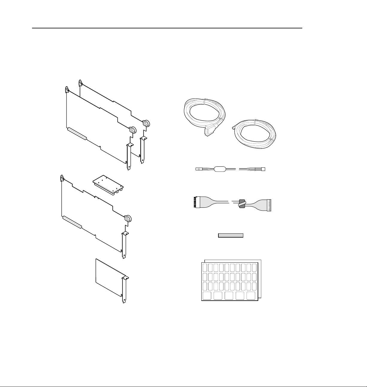
The Fibre Channel upgr ade kit for a 4-channe l Profile syste m consists of the items
listed in Table 1 and shown in Figure 1.
Table 1. 4-Channel Profile Fibre Channel Upgrade Kit Contents
Name Part Number
Fibre Channel Board 672-1462- X X
Master EDR Board 671-3795-X X
Slave EDR Board 671-3757-XX
10/100 Base T Ethernet Boar d 118-9403- X X
PCI Interconnect Board 671-3794-XX
Front Panel Cable Assy w/Fer rite Bead 174-3459- XX
LED Cable Assy w/F errite Bead 174-3471-X X
Gasket, EMI Foam 348-1543-XX
5M Fibre Channel Copper Cable 174-3629-X X
5.49M Ethernet 10/100 BaseT Cable 174-3738- XX
Standard Sticker Set 334-8982- X X
Fibre Channel Sticker Set 334-9461- X X
Installation Manual 070-9674-XX
The 2-channel upgr ade kit consists of all the items listed in Table 1 and shown in
Figure 1 except the EDR Slave board.
16 PDR 100 Fibre Channel Install ation
Page 17
Fibre Channel Upgrade Kits
Enhanced Disk
Recorder Boards
PCI Board
Fibre Channel
Board
5 meter Fibre
Channel Cable
5.49 meter
Ethernet Cable
LED Cable
Front Panel Cable
EMI Gasket
Label Sets
10/100 Base T
Board
Figure 1. 4-Channel Fibre Channel Kit Contents
PDR 100 Fibre Channel Installation 17
9674-1
Page 18

PDR 100 Fibre Channel Installation
Fibre Channel Kit Description
The Fibre Channel upgr ade provides for connect ivity and high speed data t ransfers
between Profile systems. A LAN network (or Ethernet hub) and a Fibre Channel
hub are required to connect groups of grea ter than two Profile systems and, in
general, one set of hu bs is requ ired fo r each g roup of Profile systems to be
connected.
Fibre Cha nn e l Boa r d
The Fibre Channel (FC) board is a networkin g device which uses the Fibre
Channel Arbitrated Loop ( FCAL) protocol. The FC board is compatible with the
Peripheral Component I nterc onnect (PCI) local bus. With the on-boar d Gigabau d
Link Module (GLM), the FC board provides the functionality to network
numerous Profile systems.
Master Enhanced Disk Recorder Board
The Master Enhanced Disk Recorder (MEDR) board provides high bandwidth
data transfe rs from disk to and from video channels and the Fibre Channel board.
Additionally the i960 enhancements include a Global PCI, a Local PCI (LPCI),
and the i960 processor.
Slave Enhanced Disk Recorder Board
The Slave Enhanced Disk Recorder (SEDR) board is the same as the MEDR with
the following exceptions:
• It does not have the i960 processor section.
• Arbitration, interrupt, and clock lines are from the MEDR.
10/100 BaseT Ethernet Board
This board provides the Ethernet connection for the Profile system.
PCI Interconnect Board
This is a passive 3-conne ctor boa rd which provi des local bus connection betwee n
the Master ED R bo ard , the Slav e EDR , an d the FC board. It is attached to
connectors on the top edges of these boards.
18 PDR 100 Fibre Channel Install ation
Page 19

Front Panel Cable Assembly
This is a r eplac ement c able wit h an at tached ferr ite bea d to in sur e that your Profi le
system remains EMI compliant. Replacement of this cable is only necessary on
Profile systems with serial n umbers lower than B041685.
LED Cable
This is a r eplac ement c able wit h an at tached ferr ite bea d to in sur e that your Profi le
system remains EMI compliant. Replacement of this cable is only necessary on
Profile systems with serial n umbers lower than B041685.
EMI Foam Gas ket
This is EMI foam gasket is ins talled to insure that yo ur Profile system remains EM I
compliant. Installation of this gasket is onl y necess ary on Profile sys tems with
serial numbers lower than B041685.
Fibre Cha nn e l Cab le
The cable connecting the Profile system to a Hub is a 5 meter, copper wire cable
with a DB-9 connect or on each end. Note that other lengths of cable are available
from your Grass Valley Group representative. Also note that for distances greate r
than 25 meters, quality will begin to deteriorate and a fiber-optic cable with
copper-to-fi ber adapters is then recommended.
Front Panel Cable Assembly
NOTE: Minimum cable distances should be used to redu ce signal degradation
and error rates.
PDR 100 Fibre Channel Installation 19
Page 20

PDR 100 Fibre Channel Installation
Ethernet Cable
The Ethernet cable is a 5.49 mete r standard Ethe rnet cable with RJ-45 connectors
on each end.
Sticker Sets
A standard set of stic kers and a Fibre Channel set of stickers are provided so that
your Profile board IDs at the back of the chassis can be updated after the
installation of the Fibre Channel kit.
20 PDR 100 Fibre Channel Install ation
Page 21
Accessories
A Profile Video Network requires a n Etherne t Local Ar ea Network (LAN) to
communi cate co m mand and status info rm at ion b et ween s ystems. If your Profile
systems are not connected to an existing LAN, Grass Valley Group recommends
Ethernet connecti on to a LAN hub or switch.
Similarly, connecting more than two Profile systems to a Fibre Channel Network
requires the use of a Fibre Channel hub or switc h. In addit ion, each Profil e s ystem
more than 25 meters f rom the Fibr e C hannel hub, switch o r an other P rofil e syst em
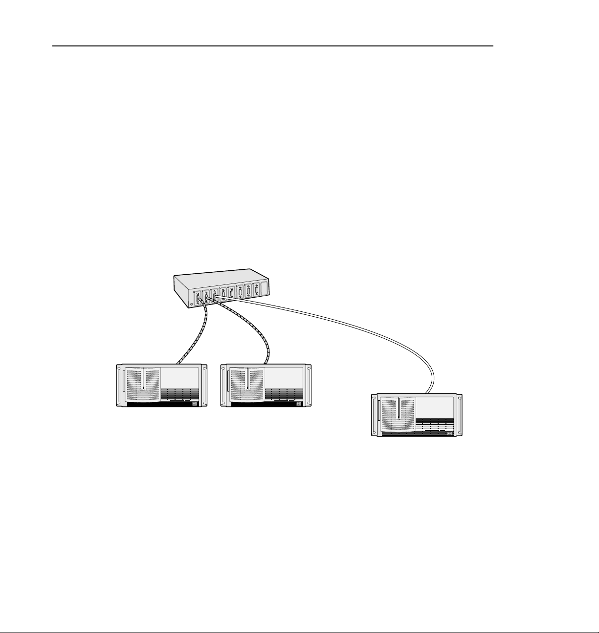
needs a fiber-optic cable and copper-to-fiber cable adap ters. Figure 2 shows an
example of connecting Profile systems up to and more than 25 meters apart.
Up to 25m
(use copper cable)
Accessories
Fibre Channel Hub
From 25m to 500m
(use fiber-optic cable)
Profile1 Profile2
0033-8
Profile3
Figure 2. Example - Profile System Fibre Channel Connections
The hubs, switches, and the adapters are not part of this Fibr e Channel kit, but m ay
be purchased separate ly by contac ting your Grass Valley Group representative.
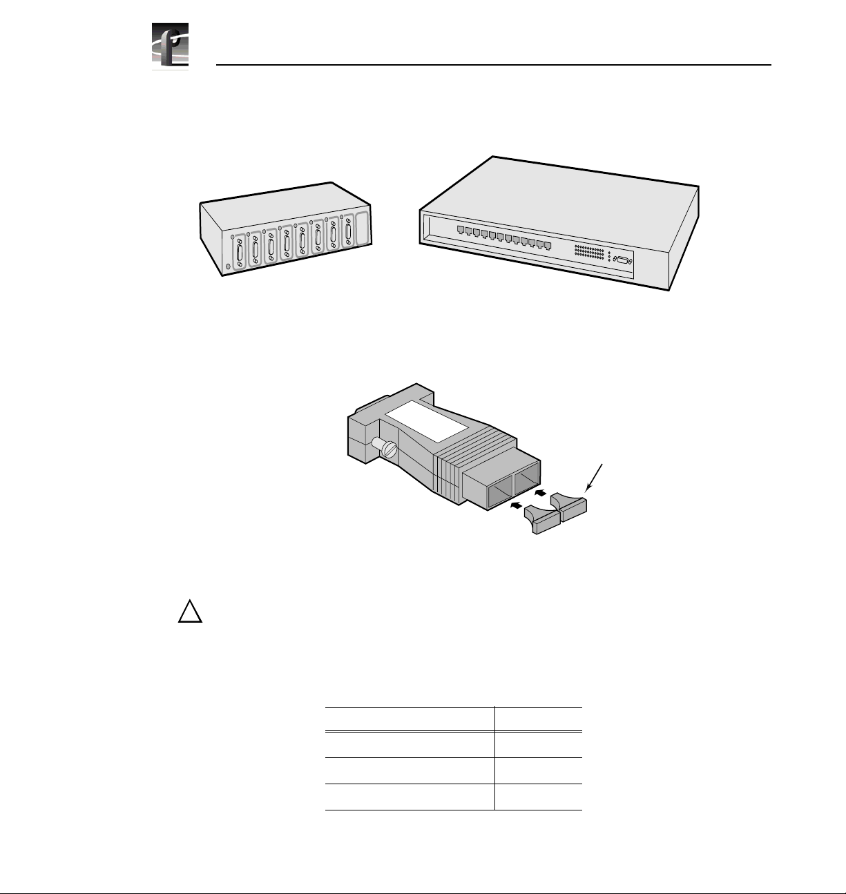
Figure 3 shows the two hubs and Figure 4 shows a copper-to-fiber cable adapter.
Table 2 lists the Hub and Adapte r part numbers.
PDR 100 Fibre Channel Installation 21
Page 22
PDR 100 Fibre Channel Installation
.
Fibre Channel Hub
Figure 3. Fibre Channel and Ethernet Hubs
9674-21
Figure 4. Copper-to-Fiber Cable Adapter
Ethernet Hub
Fiber-optic
Connector
Covers
9674-2
CAUTION: The laser diode in the Copper-to-Fiber Cable Adapter is made
!
from Gallium-Aluminum-Arsenide. Check with your local environmental
authorities for proper disposal of a malfunctioning adapter.
Table 2. Fibre Channel Netw orking Accessories
Name Part Number
Ethernet Hub PNETHUB
Fibre Channel Hub PNFCHUB
Cable Ada pter, Co pper- to-Fi ber PNF0MIA
22 PDR 100 Fibre Channel Install ation
Page 23

Networking Overview
This section contain s information about networking Profile systems and Ethernet.
Network Configurations
Ethernet and Fibre Channel provide two types of networking. Etherne t provides a
path for command and status signals from one device to another. It also allows
Windows NT file transfers between devices.
Fibre Channel provide s connectivity for high speed media data transfers between
Profile system s .
Using Fibre Channel to network groups of greater than two Profile systems
requires an existing Ethernet network (LAN) or an Ethernet hub and a Fibre
Channel hub.
Network Models
The following discusses two example s of Ethernet and Fibre Channel networking.
The first example shows connect ion of several Profile systems with an Etherne t
hub (or existing Ethernet network) and a Fibre Channel hub. The second example
of Ethernet and Fibre Channel networking shows connection of several hubs.
Networking Overview
PDR 100 Fibre Channel Installation 23
Page 24
PDR 100 Fibre Channel Installation
Networking Several Profile Systems
Hubs provide an easy and efficient method for the connection and disconnection
of machines without rewiri ng. I f you want to connect more than two Profile
systems togethe r for video ne tworking, you will need t o connect each sys tem to an
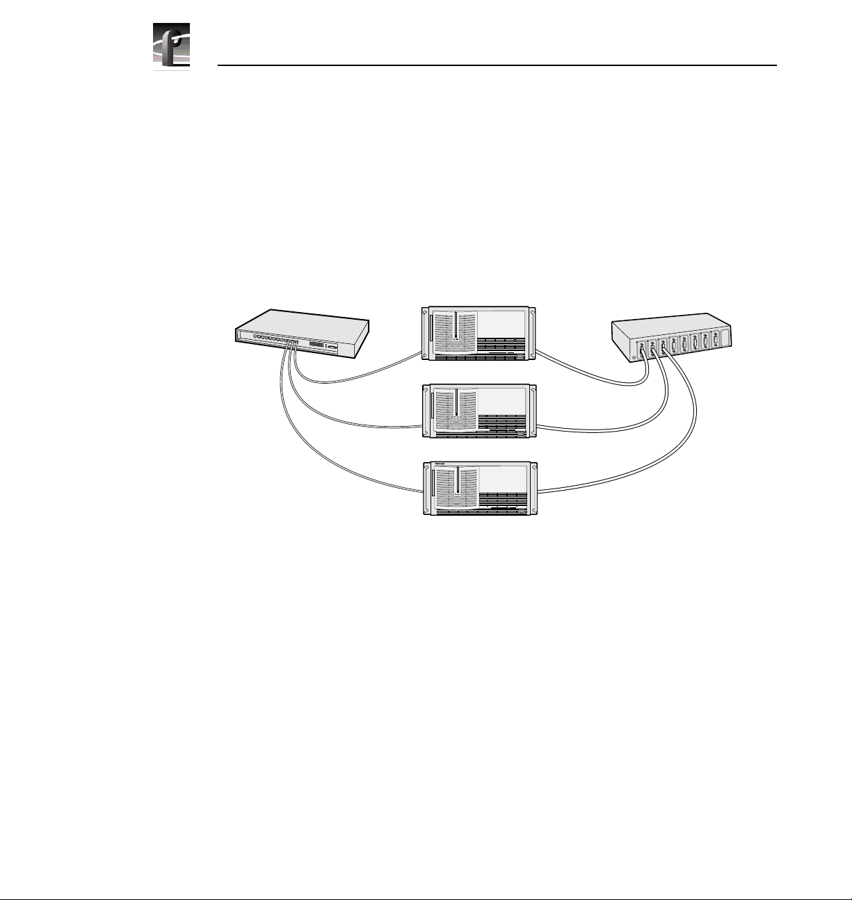
Ethernet hub or an existing Ether net network and a Fibre Channel Hub. Figure 5
shows an example of this networking.
Ethernet Hub
Profile1
Profile2
Profile3
0033-9
Figure 5. Basic Hub Connections
Fibre Channel Hub
24 PDR 100 Fibre Channel Install ation
Page 25

Network Models
Networking Several Hubs
Connecting hubs together provides a way to add more and more systems to the
network. Large Fibre Channel networks will probably not perform as well as
smaller ones due to bandwidth lim itati ons. Figure 6 shows a simple use of several
hubs.
Ethernet Hub 1
Ethernet Hub 2
Profile1
Profile2
Profile3
Profile4
Profile5
Profile6
Fibre Channel Hub 1
Fibre Channel Hub 2
0033-10
Figure 6. Using Several Hubs
PDR 100 Fibre Channel Installation 25
Page 26

PDR 100 Fibre Channel Installation
The number of hu bs re quire d depends o n th e number of conne ction s sup porte d by
each hub. Remember that one of the connections is needed to connect to the next
hub. You must use appropriate cables fo r the distance between devices.
Building a Fibre Channel Network
The simplest network connect ion is the point-to-point connection shown in
Figure 7. This method allows you to conn ect two Profile systems togeth er, which
is the ideal installation fo r initial setup to ensure that all components are working
and correctly config ured be fore adding additional Profile systems to your Fibre
Channel network.
Profile1
r
b
i
F
n
e
n
c
o
t
C
t
e
n
r
e
h
t
E
a
h
C
e
o
C
l
e
n
n
i
o
n
e
c
n
t
i
n
o
n
Profile2
0033-11
Figure 7. Point-to-point Fibre Channel Network Connection
The Ethernet connection shown in Fi gure 7 links the two LAN cards in each
Profile system. These cables may be twisted pairs up to 30 meters in length
The Fibre Channel connection shown in Figure 7 links the two Fibre Channel
cards in the two systems. This cable can be:
• Copper cable up to 25 meters.
• Multi-mode optical cabl e with a copper-to-fiber adapter up to 500 meters.
26 PDR 100 Fibre Channel Install ation
Page 27

Electrostatic Precautions
Electrostatic Precautions
!
CAUTION: This product contains components that are highly sensitive to
electrostatic discharge. To protect these components from damage and to
maintain product reliability, take the following precautions when handling
the circuit boards.
• Handle all circuit boar ds in a static -protected area capable of cont rolling
static charge on c onductive materia ls , people, and non-con ductive mate ria ls.
Static-prote cted areas include non-static table tops and non-static floor mats.
• Use a static discharge wrist strap when handling circuit boards.
• Handle the circuit board s only by the edges. Avoid touching the printed wires
on the back of the circuit board as much as possible.
• Leave the board in its static-shielded bag until you are ready to install the
board.
PDR 100 Fibre Channel Installation 27
Page 28

PDR 100 Fibre Channel Installation
Installation Procedures
!
WARNING: These procedures should only be performed by qualified se rvice
personnel.
The procedures listed below take you step-by-step through the installation of the
Fibre Channel upgrade.
• Preparing the Profile system for the upgrade.
• Installing the upgr ade.
• Verifying post-i nstallation operability.
NOTE: Unless otherwise instructe d, do not discard any items removed from
the Profile sys tem.
28 PDR 100 Fibre Channel Install ation
Page 29

Prep aring the Profile System
Before you can inst all, tes t, and operate the Fibre Channe l upgrade, Prof ile System
Software version 2.1 or higher must be insta lled and te st ed for o perabili ty, and the
tasks liste d below. In add ition to these task s, mak e sure t hat your video d ata i s
backed up.
• Enable the network
• System shutdown.
• Power off.
• Power cord and External cables disconnect.
• Profile system removal from the rac k .
• Covers removal.
• Board brackets removal.
• Removing the old Mast er Disk Recorder boa rd and, if installed, the old Slave
Disk Record er bo ard .
A board location guide and audio clock cabling information is included to as sist
you if you must move boards around in order to instal l the Fibre Channel upgra de.
Preparing the Profile System
Enable the N etwork
Network service s must be r unning r egardle ss of whether or no t yo u cur rently ha ve
a LAN board installed. To enable the network, from a Command Prompt, type in:
netenabl and then press
Return.
System Shut dow n
To shut your Profile system down without loss of data, you will need to:
• Shut down the Profile Applicat ion software.
• Close any other processes whic h may be running.
• Close Windows NT.
• Switch power off.
PDR 100 Fibre Channel Installation 29
Page 30

PDR 100 Fibre Channel Installation
External Cables Disconnect
NOTE: Making a diagram or note of cable connecti ons wil l make it e asier to
reconnec t the cab les .
Disconnect the power cord, all cable s, and any SCSI te rminators from the Profile
rear panel.
Profile Chassis Removal
To remove the Prof ile chassi s from the equ ipment rack:
!
!
WARNING: Unless the equi pment rack is adeq uat el y anch o r ed, th e rac k
could tip when the Profile chassis is extended on the rack slides. To avoid
possible injury to person nel or damage to the equipm ent, make sure th e rack
is firmly anchored before exte nding the Profile chassis on the rack slides.
1. Loosen the Pr ofile chassis retaining screw which secures the Profile chassis
to the rack.
2. Use the Profile chass is front panel handles to sli de the chassis out of the rack
until the rack slide locks engage.
WARNING: The Profile chassis is too heavy for one person to remove from
an equipment rack. To avoid possible injury to personnel or damage to the
equipment, get help when removing the Profile chassis from the rack.
3. Being sure to fully support the Prof ile chassis, depress the slide locks and
slide the chassis out free of the rack and place on a flat level surface with
enough room to work around it.
Covers Removal
There are two covers which need to be removed to gain access to the board area:
the disk drive top cover and the board area top c over. The disk drive cover acts as
a hold down for the board area cover and therefore must be removed first. See
Figure 8.
NOTE: If your PDR100 has been upgraded to 9GB disk drives, it will have
more disk drive cover screws than shown in Figure 8.
30 PDR 100 Fibre Channel Install ation
Page 31

Preparing the Profile System
1. Use the Torx tool with the T10 tip to remove the top screws and use the T15
tip to remove the side screws, if present, which secure the disk drive cover
Ê
to the chassis and remove the cover.
2. Use the Torx tool with the T10 tip to remove the screws which secure the
Ë
board area cover
.
2
1
9496-1
Figure 8. Profile Top Covers Removal
PDR 100 Fibre Channel Installation 31
Page 32

PDR 100 Fibre Channel Installation
Board Retainer Brackets Removal
There are two re tainer brackets l ocated in the board area that must be removed in
order to remove circuit boards. One is slotted so that it holds full size boards in
place and helps maintain their ali gnment. Although the other bracket holds short
boards in place, it must also be removed to remove any full siz e boards. This
bracket has extenders which may be moved to adapt to the locations of any short
boards. See Figure 9 for locations and removals of the two board retaine r brackets.
To remove the board hold-down bracket s, r efe r to Figure 9 and:
1. Use the Torx tool with the T10 bit to remove retaining sc rew
slotted bracket from the side of the Prof ile chassis.
2. Lift bracket
3. Use the Torx tool with the T10 bit to remove retaining sc rew
middle of the short board bracket.
4. Lift bracket
Ë
up and out of the chassis.
Í
up and out of the chassis.
Ê
for the top
Ì
from the
32 PDR 100 Fibre Channel Install ation
Page 33

Preparing the Profile System
3
4
1
2
9674-13
Figure 9. Board Retainer Bracket s Rem oval
PDR 100 Fibre Channel Installation 33
Page 34

PDR 100 Fibre Channel Installation
Removing Internal Cables
The internal cables you remove dep ends on whether you have 2-channel or a
4-channel PDR100 (see Figure 10).
For a 2-channel PDR100:
• Remove the SCSI A Cable connector
board.
For a 4-channel PDR100:
• Remove the SCSI A cable connector
board.
• Remove the SCSI B cable connector
• Remove the short ribbon cable
Recorder board an d the Slav e D isk Recorder board .
It may be necessary to move boards around to accommodat e the slot requirements
for the Fibre Channel board and the new EDR boards. If moving boards a round
requires re moval of any int ernal cables, Gra ss Vall ey Gro up re commends making
a diagram of the internal cable connections prior to moving an y boards to make it
easier to reconnect internal cables. Refer to the “Board Location Guide” on
page 38 and “Audio Clock Cabling” on page 48 for additional information.
Ì
from the Master D isk Recorder
Ê
Ê
from the Master Disk Recorder
from the Slave Disk Recorder board.
Ë
connected b etw een the Mast er D isk
34 PDR 100 Fibre Channel Install ation
Page 35

Preparing the Profile System
3
1
2
9674-9
Figure 10. Interna l SCSI Cables Rem oval
PDR 100 Fibre Channel Installation 35
Page 36

PDR 100 Fibre Channel Installation
Removing Old Boards
If you currently have a 2-channel PDR100 system, you must remove the Master
Disk Recorder board. I f you curr ently have a 4- channel syst em, you must re move
the Master Disk Recorder and the Slave Disk Recorder boards. Also, for both
2-channel and 4-channel systems, if you currently have an Ethernet 10 BaseT
board, you must remove that board.
To remove the old Master and, if installe d, Sl ave Disk Recorder boards:
1. Use the Torx tool with the T15 tip to remove the screws which secure each
board to the rear panel (see Figur e 11 for an example).
2. Use the extraction lever on the front of each boa rd and the extracti on ring at
the back of each board to lift the circuit board free of the connectors on the
motherboard.
1
Figure 11. Typical Removal of a Full Size Board
36 PDR 100 Fibre Channel Install ation
2
9040-13
Page 37

Preparing the Profile System
If necessary to remove an Ethernet 10 BaseT board, which is a short board, see
Figure 12 for an example and:
1. Use the Torx tool with the T15 tip to remove the board bracket retaining
screw from the inside of the rear panel.
2. Carefully but firmly gra sp the boar d and lift it straight up and out of the
chassis. Note that you may ha ve to remove an adjacent full size board in order
to safety grasp the Ethernet 10 BaseT board.
Figure 12. Typical Removal of a Short Board
PDR 100 Fibre Channel Installation 37
9674-18
Page 38

PDR 100 Fibre Channel Installation
Board Location Guide
This board location guide ide ntifies the inputs and outputs of each Profi le board
currently avail able for a PDR100, as well as the input and output connections on
the Video Router connectors on the motherboard. Use this information when:
• you add a new circuit board to the Profile system and need to select a slot
into which you can install it;
• you need to move boards around to meet requirements for new boards.
As you move boards around, remember that some circuit boards must occupy
specific slots , while others can be installed in almost any slot a s long as their I/O
requirements are met.
This section provides a simple approach to board location. It explains the
relationship bet ween the motherboard a nd Video Router connect ors and provide s
tables, charts and examples to as sist you in installing boards.
Video Router to Motherboard Relationship
The Video Router provides and controls video data to twelve connectors on the
motherboard. These video dat a connectors are align ed with the main motherboard
connectors for slo ts J5 through J16. Since the Ref Gen board must oc cupy J16 to
provide the necessary system clocks, this discussion excludes J16.
When choosing a slot for a board, the major constraint on a slot is how the board
connects to the Video Router. Not all boa rds requir e the same nu mber of video I/O
connections, and not all video data connectors provide the same number of video
I/O connections. Therefore, you must know how many input and output
connections the board need s, and the slot available that meets those needs.
Board I/O Requirements and Restrictions
Table 3 lists each of the boards which may be installed in the Profile system and
the recommended slots, possible alternatives, and restrictions for each board.
Note that if more than one slot is recommended or possible for a board, those slots
are listed in the order of preference.
38 PDR 100 Fibre Channel Install ation
Page 39

Table 3. Board I/O Requirements and Restrictions
Board Location Guide
Board Video Router
Connection
Requirements
Inputs Outputs
CPU n/a n/a J1 None Reserved for PC card only
VGA n/a n/a J2 None ISA only
LAN n/a n/a J3 None EISA only
SCSI n /a n/a J4 None EISA only
RefGen n/a n/a J16 None Reference genlock
RS-422 n/a n/a J17 None EISA only
Master Disk
Recorder
Slave Dis k
Recorder
Analog
Compos ite In
Analog
Composite
Decoder
Four Ch annel
Analog Out
Analog
Composite
Monitor Out
Analog
Compos ite I/O
Serial Digital I/O 2 2 any slot J5-J15 any open slot if board in adjacent slot does
CAV In None 1 any slot J5-J15 any open slot if board in adjacent slot does
Fibre Channel None None J13 None Must be adjacent to Master Disk Recorder.
Mix Effe cts 6 2 J6 J7 Only J6 and J7 have 5 dedicated inputs;
Audio Signal
Processing
Board (ASPB)
2 2 J14 Non e Must be adja cent t o Slave Disk R ecorder and
2 2 J15 None Must be adjacent to Mas ter Disk Re corder.
None 1 any slot J5- J 15 Any open slot if board in adjacent slot does
None None any slot J4-J15 Must be adjacent to Analog Composit e In.
4 None J11,J12 J6,J7 Only J6, J7, J11, and J12 have 4 (or more)
4 None J11,J12 J6,J7 Only J6, J7, J11, and J12 have 4 (or more)
2 2 any slot J5-J15 any open slot if board in adjacent slot does
None None any slot J5-J15 Cables must be able to reach video boards
Recommended
Slots
Other
Possible
Slots
Comments
Fibre Channel (if insta lled).
not use the same sha red rout e r poi nt s. Mu st
be adjacent to the Analog Composite
Decoder.
May be installed in J4 since it does not
require any router connections.
inputs. If in J11 or J12, board must be able to
get a s hare d in pu t (t he 4 t h) fr om an adj ace nt
slot (J1 0 or J1 3).
inputs. If in J11 or J12, board must be able to
get a s hare d in pu t (t he 4 t h) fr om an adj ace nt
slot (J1 0 or J1 3).
not use the same sh ared rout er points.
not use the same sh ared rout er points.
not use the same sh ared rout er points.
PCI Interconnect required.
board must be ab le to get a sha red i nput ( the
6th) fr om an adjacent slot (J5 or J8).
or additional ASPB. Second ASPB
nece ss a r y for 32 channels of audio.
PDR 100 Fibre Channel Installation 39
Page 40

PDR 100 Fibre Channel Installation
Video Router I/O Connections
Now let’s look at th e Video Router connections available at slots J5-J15. Table 4
is a board location chart with the Video Router input and output connections. In
the table:
• The Slots column lists each slot on the motherboard connected to the Video
Router.
• The Board column is where you e nter the boards curren tly installed and the
name of the board you want to install.
• The Inputs column identifi es data input connections to the slots (boards)
from the Video Router. The numbers in the blocks correspond to the order
input connections are assigned at the Video Router connector.
• The Outputs column identifies data output connections from the slots
(boards) to the Video Router. The numbers in the blocks correspond to the
order output connecti ons are assigned at the Video Router connector.
• The shaded blocks in the d iagram indicate Video R outer conn ections sha red
between slots. A shar ed connec tion is avail abl e to eithe r slot, but not both at
the same time.
For instance :
• The shaded blocks between slots J5 and J6, slots J7 and J8, slo ts J10 and J11,
and slots J12 and J13 indicate shared input connections.
• The shaded blocks between slots J8 and J9, slots J10 and J11, and slots J12
and J13 indicate shared output c onne ctions.
40 PDR 100 Fibre Channel Install ation
Page 41

Table 4. Board location chart
Slot Board Input Output
J5
1
23
J6
J7 1 1
2
3
42
5
6
J8
J9 1
22
J10 1 1
2 34
J11
J12 1 1
22
3
4 34
J13
J14 1 1
23
J15 1 1
23
1
2
62
5
4
31
2
1
21
12
34
43
2
4 43
32
2
11
2 43
12
2
2
Board Location Guide
1
1
PDR 100 Fibre Channel Installation 41
Page 42

PDR 100 Fibre Channel Installation
Selecting a Location
Here’s how to use the tables to select a location for a board.
1. In the Board Location C hart, Tab le 4, enter the board name and, referring to
Board I/O Requ irements a nd Restrictio ns, Table 3, put a check mark i n each
input and output block u sed by each board cu rrently inst alle d in your Profil e
syst e m. Start with the 1 block for each board.
2. Look in the Board I/O Requirements and Restric tions, Table 3, to see the
input and output requirements and both the recommended slot and
alternative slots for the board you want to install.
3. Look in the B oard Location Chart, Ta ble 4, for a slot with the r equired Vide o
Router connections avai lable. Starting with the 1 block, put an “X” in each
block that correspond s to an input and output r equirement for the board. If
the recommended slot is occupied, or there are not enough input or output
blocks avail abl e, lo ok at the al te rnat iv e slo ts.
4. If all input and output requirements for the board match the available ones
for the slot , write the b oard name in the Boa rd column for the slot and in stall
the board.
NOTE: If you can’t find an open slot with the I/O which meets the I/O
requirements of the board you want to instal l, y ou will have to move boards
around. You can use the Boa rd I/O Requiremen ts and Restri ction s table an d
the Board Locat ion Chart to experim e nt with various board locations be fore
deciding on one.
The following examples de monstrate how to u se the Board I /O Requirements and
Restrictions, Table 3, and the Board Location Chart, Table 4.
42 PDR 100 Fibre Channel Install ation
Page 43

Board Location Guide
Example 1
This example shows how to use the Board I/O Requirements and Restrictions,
Table 3, and the Board Loca tion Chart, Table 4, to install a Fibre Channel upgrade
into a 4-channel PDR100 with two Serial I/O boards and four Audio I/O boards.
In all likelihood, you will have to move boards before you can install the Fibre
Channel upgrade. Move the boards bef ore using the Board Location Chart. For this
example:
1. Move the Serial I/O in slot J8 to slot J7.
2. Move the Audio I/O board in slot J9 to slot J8.
3. Move the Audio I/O board in slot J10 to slot J9.
4. Move the Serial I/O in slot J11 to slot J10.
5. Move the Audio I/O board in slot J12 to slot J11.
6. Move the Audio I/O board in slot J13 to slot J12.
7. Now fill in the Board Location Chart.
a. For the Serial I/O in slot J7, which requires two inputs and two outputs:
- Write Serial I/O in Slot 7.
- Put check marks in the 1 and 2 Input blocks for J7.
- Put check marks in the 1 and 2 Output blocks for J7.
b. For the Audio I/O boards in slots J8 and J9, which requi re no Video Router
connections:
- Write Audio I/O in Slot J8 and Slot J9.
c. For the Serial I/O in slot J10, which requires two inputs and two outputs:
- Write Serial I/O in Slot 10.
- Put check marks in the 1 and 2 Input blocks for J10.
- Put check marks in the 1 and 2 Output blocks for J10.
d. For the Audio I/O boards in slots J11 and J12, which require no Video
Router connections:
- Write Audio I/O in Slot J11 and Slot J12.
PDR 100 Fibre Channel Installation 43
Page 44

PDR 100 Fibre Channel Installation
8. From the Board I/O Requirements and Restri ctions, Table 3, note that:
a. The Slave EDR board requires two inputs and two outputs and must be
adjacent to the Mast er E DR b o ard.
b. The Master EDR boar d requires two inputs and two outputs and must be
adjacent to both the Slave EDR and the Fibre Channel boa rds.
c. The Fibre Channel board does not require inputs or outputs but must be
adjacent to the Mast er E DR b o ard.
9. Looking at your Board Location Chart reveals that slots J13, J14, and J15
meet requirements for all three boards.
10. For the Slave EDR board:
- Put Xs in the 1 and 2 Input blocks for J13.
- Put Xs in the 1 and 2 Output blocks for J13,
- Write Slave EDR in the Boards column for Slot J13, and install the board.
11. For the Master EDR board:
- Put Xs in the 1 and 2 Input blocks for J14.
- Put Xs in the 1 and 2 Output blocks for J14.
- Write Master EDR in the Boards column for Slot J14, and install the bo ard.
12. Write Fibre Channel in the Boards column for slot J15 a nd install the board.
• Your Board Location Chart would the n look similar to Table 5, “Example 1
- Installing the Fibre Channe l Upgrade,” on page 45.
44 PDR 100 Fibre Channel Install ation
Page 45

Table 5. Example 1 - Installing the Fibre Channel Upgrade
Slot Board Input Output
J5
J6
J7 Serial Digital I/O 1
J8 Analog Audio I/O
J9 Analog Audio I/O 1
J10 Serial Digital I/O 1
J11 Analog Audio I/O
J12 Analog Audio I/O 1 1
J13 Fibre Channel
J14 Master Enhanced
Disk Recorder
J15 Slave Enhanced
Disk Recorder
1
23
2
3
42
5
6
22
2
22
3
4 34
1 X 1 X
2 X 3
1 X 1 X
2 X 3
1
2
62
5
4
31
2
1
3
1
3
3
3
21
12
34
43
1
3
3
3
2
3
34
4 43
32
2
11
2 43
12
2 X
2 X
Board Location Guide
1
1
PDR 100 Fibre Channel Installation 45
Page 46

PDR 100 Fibre Channel Installation
Example 2
If you next want to install a Mix Effects board:
1. From the Board I/O Requirements and Restrictions table, note that the Mix
Effects board require s six inputs and two outputs and that the first
recommended slot is J7 with slot J6 another possibility.
2. Looking at your Board Location Chart , you see tha t slot J7 is occupied but
that slot J6 is open and although it only has five Inputs, t he 6th Input can be
the input shared with J5, which is open.
3. On your Board Location Chart for the Mix Effects boa rd :
- Put Xs in the 1-5 Input blocks for J6.
- Put an X in the shared Input block for J5.
- Put Xs in the 1 and 2 Output blocks for J6.
4. Write Mix Effects in the Board column for slot J6 and ins tall the board.
• Your Board Location Chart would the n look similar to Table 6, “Example 2
- Installing a Mix Effects Boar d,” on page 47.
46 PDR 100 Fibre Channel Install ation
Page 47

Table 6. Example 2 - Installing a Mix Effects Board
Slot Board Input Output
J5
J6 Mix Effects
J7 Serial Digital I/O 1
J8 Analog Audio I/O
J9 Analog Audio I/O 1
J10 Serial Digital I/O 1
J11 Analog Audio I/O
J12 Analog Audio I/O 1 1
J13 Fibre Channel
J14 Master Enhanced
Disk Recorder
J15 Slave Enhanced
Disk Recorder
1
23
2
3
42
5
6
22
2
22
3
4 34
1 X 1 X
2 X 3
1 X 1 X
2 X 3
1
2
X 6 X 2
X 5
X 4
X 3 X 1
X 2
X 1
3
1
3
3
3
21
12
34
43
1
3
3
3
2
3
34
4 43
32
2
11
2 43
12
2 X
2 X
Board Location Guide
1
1
PDR 100 Fibre Channel Installation 47
Page 48

PDR 100 Fibre Channel Installation
Audio Clock Cabling
This section provides some general rules about audio clock cabling. Audio clock
signals from the appropr iate video board synchronize the audio to the video during
Record. Internal cabling between connectors on the top of the video boards and
connectors on the top of the audio board s provide the clock signals to the audio
boards.
In general, the video board in the lowest numbered slot provides the audio clock
signal to an Audio I/O board, the video board in the next lowest numbered slot
provides the audio clock signal to another Audio I/O board, etc.
Figure 13 shows an example of internal audio clock cabling. In Figure 13, Serial
I/O boards, installed in slots J 7 and J10, are the only v ideo boards. The audio c lock
cable connect io n s are:
• Channel 1 of the Seria l I/O board in slot J7 t o Audi o 1 (PLAY) on t he Audio
I/O in slot J8
• Channel 2 of the Seria l I/O board in slot J7 t o Audi o 2 (PLAY) on t he Audio
I/O in slot J9
• Channel 1 of the Serial I/O board in slot J10 to Audio 3 (RECORD) on the
Audio I/O in slot J11
• Channel 2 of the Serial I/O board in slot J10 to Audio 4 (RECORD) on the
Audio I/O in slot J12
• PLAY from all four Audio I/O boards to the system clocks on the RefGen
board.
Note that Figure 13 is an example with video boards only in slot s J7 and J10. If
you have other video boards in lower numbered slots, you will have to determine
how you want to set your system up. You will have to remove any unused clock
cables and you may have to move boards around to accommodate your setup.
Also note that you must be su re to connect audio sources associated with a video
board to the correct XLR connectors on the audio bre akout box.
48 PDR 100 Fibre Channel Install ation
Page 49

Audio Clock Cabling
J17 J13J16
Ref Gen
J11 J9
J15 J14 J6J7
Play
Record
J12
Audio 4
J10
Serial I/O
Audio 3
J8
Audio 1
Audio 2
Ch. 2
Ch. 1
Serial I/O
J5
J4 J3
9674-30
Figure 13. Example of Audio Clock Cabli ng
PDR 100 Fibre Channel Installation 49
Page 50

PDR 100 Fibre Channel Installation
Installing the Fibre Channel Upgrade
Figure 14 identifies the board slot IDs and Figure 15 shows the locations a nd slot
IDs for the Slave EDR, Master EDR, and Fibre Channel boards. Installing the
Fibre Channel upgrade consists of the tasks listed below.
• Installing the 10/100 Base T board, the Slave and Master EDR boards, and
the Fibre Channel board.
• Reinstalling board hold- down brackets.
• Reconnecting interna l cable s.
• Installing the PCI Inte rconnect board.
• Installing EMI complianc e components, if necessary.
• Replacing the Profile cov ers.
• Replacing the Profile chassis into the rack.
• Connecting/rec onnecting external cables and power cord.
NOTE: After board relocation s, the slot ID stickers on the bott om rear panel
will no longer be valid. If you need new ID stickers, contact your Grass Valle y
Group representativ e.
50 PDR 100 Fibre Channel Install ation
Page 51

Installing the Fibre Channel Upgrade
J17 J13J16
J15 J14 J6J7
Figure 14. Board Slot IDs (Rear Panel)
J12
J11 J9
J10
J8
J5
J4 J3 J2
J1
9674-19
PDR 100 Fibre Channel Installation 51
Page 52

PDR 100 Fibre Channel Installation
Figure 15. Slave EDR, Master EDR, and Fibre Channel Board Locations
Slave (J13)
Master (J14)
Fibre Channel (J15)
9674-16
52 PDR 100 Fibre Channel Install ation
Page 53

Installing the Ethernet 10/100 BaseT Board
Installing the Ethernet 10/100 BaseT Board
The Ethernet 1 0/100 BaseT board is a short board, which must be installed in slot
J3. See Figur e 16 for an installati on example a nd i nstall th e 10/100 baseT b oard as
follows:
1. If you did not have an Ethernet board, use the Torx tool with the T15 tip
remove the slot blank from J3.
2. Slip the 10/100 BaseT board into the board area ali gning it with the
connectors in the mother board at the bottom panel and the rear panel cutout
for J3.
3. Ensure that the board contacts a re corr ectly aligned with the motherboard
connectors and firmly press down on the board until it is fully seated. Screw
holes in the board bracket should a li gn with the two bracket mounting scr ew
holes, one on the inside and one on the outside of the rear pa nel.
4. Use the Torx tool with the T15 bit to secure the 10/100 BaseT boar d bracket
to the rear pa nel with the screw removed either when the old Ethernet board
was removed or when the slot blank was removed (step 1).
PDR 100 Fibre Channel Installation 53
Page 54

PDR 100 Fibre Channel Installation
Figure 16. Short Board Installation Example (Top View)
54 PDR 100 Fibre Channel Install ation
9674-11
Page 55

Installing the EDR Boards
See Figure 17 to distinguish between the Master EDR board and the Slave EDR
board, where the Master EDR contains the i960 Controller. See Figure 14 for slot
IDs and Figure 18 for an example of installing a full size board. To inst all the EDR
boards, proceed as follows:
1. If you have a 2- channe l PDR100, start at step 5, o therwi se continue t o step 2.
2. Slip the Slave EDR board into the board slide at the front of the board area
for slot J13 aligning it with the e dge-board connectors in the motherboard at
the bottom panel and the rear panel cutout for J13.
3. Ensure that the board contacts a re corr ectly aligned with the motherboard
connectors and firmly press down on the board until it is fully seated. Screw
holes in the board bracket should a li gn with the two bracket mount ing scr ew
holes, one on the inside and one on the outside of the rear pa nel.
4. Use the Torx tool with the T15 bit to secure the Slave EDR board bracket to
the rear panel with the two screws previously removed, but do not fully
tighten until afte r the PCI Interconnect board has been install ed.
5. Slip the Master EDR board into the board slide at the front of the board area
for slot J14 aligning it with the e dge-board connectors in the motherboard at
the bottom panel and the rear panel cutout for J14.
Installing the EDR Boards
6. Repeat step 3 and 4.
PDR 100 Fibre Channel Installation 55
Page 56

PDR 100 Fibre Channel Installation
Master EDR Slave EDR
i960
Figure 17. Distinguishing Between Master and Slave EDRs
9674-23
56 PDR 100 Fibre Channel Install ation
Page 57

Installing the EDR Boards
9674-7
Figure 18. Installing a Full Size Board Exam ple
PDR 100 Fibre Channel Installation 57
Page 58

PDR 100 Fibre Channel Installation
Installing the Fibre Channel Board
The Fibre Channel boa rd must be installe d in slot J15, ad jacent to the Maste r EDR
board. To install the Fibre Channel board, refer to Figure 14 and Figure 15
(page 52) for loca tion, and Figure 18 (page 57) for installation information and
proceed as follows:
1. Slip the Fibre Channel board into the board slide at the front of the board area
for slot J15 ali gning i t wit h the edge-boa rd c onnector s in t he motherboa rd at
the bottom panel and the rear panel cutout for J15.
2. Ensure that the board contacts a re corr ectly aligned with the motherboard
connectors and f irmly press down o n the board until i t is f ully se ated. S crew
holes in the board bracket should align with the two brack et mounting screw
holes, one on the inside and one on the outside of the rear pa nel.
3. Use the Torx t ool wi th t he T15 bit to secur e the Fibre Chann el board bracket
to the rear panel with the two screws provi ded, but do not fully tighten unti l
after the PCI Interconnect board has been installed.
58 PDR 100 Fibre Channel Install ation
Page 59

Reinstalling Internal Cables
Figure 19 shows ins tal lation o f the SCSI cable conne ctors. R efer to Fi gure 19 and:
Reinstalling Internal Cables
1. Connect the cab le label led SCSI A (
on the Master EDR board.
2. For a 4-channel PDR100, connect the cable labelled SCSI B (
Figure 19) to the heade r connector on the Slave EDR.
3. From your diagram, reconnect all other previously removed interna l cables.
in Figure 19) to the header connector
Ê
in
Ë
2
1
Figure 19. SCSI Cable Connections
PDR 100 Fibre Channel Installation 59
9674-17
Page 60

PDR 100 Fibre Channel Installation
Installing the PCI Interconnect Board
The PCI Interconnect board has thr ee conn ectors which attach to edge-board
contacts on the Sl ave EDR, the Maste r EDR , and the Fi bre Ch a n ne l board s . Se e
Figure 20.
J1
Index Notch
Master
J2
J3
9674-15
Figure 20. PCI Interconnection Board
The PCI board connector s are keyed to ensure correct orientation and the bottom
of the board identifies the connec tors as J1, J2, and J3. J2 is further identifie d as
MASTER. To install the PCI board, refer to Figure 21 and proceed as follows:
1. Hold the PCI with the connectors pointing down and the connector
identifica tion s tow ard s the rear of the Profile chas s is.
2. Align the PCI connector s so that J1 is over the Slave EDR header connector,
Master J2 over the Master EDR header connector, and J3 over the Fibre
Channel header connect or, and the connector keys are over the index notc hes
on the boards.
60 PDR 100 Fibre Channel Install ation
Page 61

Installing the PCI Interconnect Board
9674-10
Figure 21. PCI Interconnect Board Installation
3. Attach the PCI boar d by gent ly but firmly pre ssi ng down until t he PCI bo ard
is fully seated on all three b oard s .
4. Tighten the screws which secure the EDR boards and the Fibre Channel
board to the chass is .
PDR 100 Fibre Channel Installation 61
Page 62

PDR 100 Fibre Channel Installation
Reinstalling Board Ret ainer Brackets
Before re-inst alling the short board retainer bra cket, check it against the lay- out of
the boards. Ensure that an extender is in every location where a short board is
installed and that none are in locations where full sized boards are installed.
NOTE: To prevent damage to the Analog Composite Monitor board, if
installed, ensure that an extender is not installed at the Analog Composite
Monitor board location.
To move a short board b racket extender, refer to Fig ure 22 and procee d as follows:
1. Use the Torx tool with the T15 bit and remove extender retaining screw
Ê
from the bracket.
2. Move the extender to the desired location on the bracket.
3. Ensure that the extender align ment nub is in the hole on the bracket and
Ë
replace retaini ng screw
1
Figure 22. Short Board Retainer Bracket and Extender
.
2
9674-6
To re-install the shor t board reta iner bracket, refer to Figur e 23 and proceed as
follows:
1. Insert bracket
Ê
into the board area and ensure that the extenders are on the
top edge of all short boards.
62 PDR 100 Fibre Channel Install ation
Page 63

Reinstalling Board Retainer Brackets
2. Use the Torx tool with the T10 bit to replace brack et retaining screw Ë.
2
1
4
3
9674-14
Figure 23. Board Retainer Bracket installati on
To reinstall the full siz e board retainer bracket refer to Figur e 23 and proceed as
follows:
1. Place bracket
Ì
over the boards.
2. Align the full size boa rds to the co rrect br acket s lots (see ins ert i n Figur e 23)
and carefully seat the bracket onto the boards.
PDR 100 Fibre Channel Installation 63
Page 64

PDR 100 Fibre Channel Installation
3. Use the Torx tool with the T10 bi t to r eplace bracket r etaining sc rew Í at the
side of the Profile chassis.
Installing EMI Compliance Components
NOTE: This procedure is only necessary if your PDR100 serial number is
below B041650.
To ensure that your PDR100 remains compliant with EMI standards with the
Fibre Channel upgrade installed, you must:
1. Remove two cables be hind the front panel and replace them with the cables
included in this upgrade kit.
2. Install a gasket inside the rear panel behind the power supply.
The following procedures explain how to perform these modifications.
To replace the ca b le s:
The front panel cable assembly, Figure 24, and the LED cable assembly,
Figure 25, are on the bezel behind the front panel.
Figure 24. Front Panel Cable Assembly
64 PDR 100 Fibre Channel Install ation
9674-25
Page 65

Installing EMI Compliance Components
Figure 25. LED Cable Assembl y
Figure 26 shows removal of the front panel and bezel.
9674-24
1. Refer to Figure 26 and remove the PDR100 handles (
front panel metal pl ate (
in Figure 26) to access the two cables on the bezel .
Ë
in Figure 26) and
Ê
PDR 100 Fibre Channel Installation 65
Page 66

PDR 100 Fibre Channel Installation
Figure 26. Removing the Front Panel and Beze l
66 PDR 100 Fibre Channel Install ation
Page 67

Installing EMI Compliance Components
2. Refer to Figures 24, 25, and 27 and replace the front panel and LED cable
assemblies.
3. Refer to Figure 26 and reinstall the front panel metal plate, be zel, and
handles.
9674-28
Figure 27. Inst alling the Front Panel and LED Cable Assemblie s
PDR 100 Fibre Channel Installation 67
Page 68

PDR 100 Fibre Channel Installation
To install the EMI foam gasket:
1. Use the Torx tool with the T15 tip to remove the screws which secure the
power supply to the side of the chassis.
2. Refer to
in Figure 28 and slide the power supply toward the front of the
Ê
chassis approximately 1 inch.
3. Remove the protective str ip from the adhesive on the EMI gasket.
4. Carefully slip the gasket into the chassis between the power supply and the
rear panel and attach it to the chassis just below the power cord connector
cut-out as shown at
in Figure 28.
Ë
5. Slide the power supply back into its or iginal position and secure it to the
chassis with the screws previously removed.
2
1
Figure 28. Installi ng the EMI Gasket
68 PDR 100 Fibre Channel Install ation
9674-29
Page 69

Attaching Slot ID Stickers
Two sets of self-a dhesive stickers are inc luded as part of the Fib re Channel kit. One
set is for the new boards. The other set allows you to r e-ide ntify sl ots as a res ult of
any board m ovement wh ich wa s nece ssar y due to instal lation of t he F ibre Channel
kit. Figure 29 shows the locations for the new stickers. If you need additional or
different stickers, contact your Grass Valley Group representative.
Attaching Slot ID Stickers
9674-22
Fibre
Channel
EDR
Master
Figure 29. Sticker Slot IDs for Ne w Boards
EDR
Slave
10/100 Base T
Ethernet
PDR 100 Fibre Channel Installation 69
Page 70

PDR 100 Fibre Channel Installation
Replacing the Profile Covers
See Figure 30 and replace covers as follows:
1. Set board area cover
replace the twelve cover screws; eight on top and four from the side.
2. Set disk drive cover
tips to replace the cover with the screws previously removed.
NOTE: Your PDR100 may have more disk drive cover scre ws than sh own in
Figure 30.
Ê
in place and use the Torx tool with the T10 bit to
Ë
in place and use the Torx tool with the T10 and T15
1
2
Figure 30. Profile Cover Replacements
70 PDR 100 Fibre Channel Install ation
9674-12
Page 71

Reinstalling the Profile Chassis into the Rack
Reinstalling the Profile Chassis into the Rack
To reinstall the Profile chassis into the equipment rack:
WARNING : Un les s the eq uip m ent rac k is adequa t ely a nch o red , it coul d tip
when the Profile chassis is extended on the rack slides. To avoid possible
injury to pe rsonnel or dama ge to the equip ment, make sure the rack is firmly
anchored before extending th e Profile chassis on the rack slides.
WARNING: The Profile chassis is too heavy for one person to install in an
equipment rack. To avoid possible injury to personnel or damage to the
equipment, get help when re-installing the Profile chassis into the rack.
1. Being sure to fully suppo rt the Profile chassi s, slide it into the rac k slides until
the slide locks engage.
2. Depress the slide locks and slide the Profile chassis completely into the rack.
3. Tighten the retaini ng screw to secure the Profil e chassis in t he rack.
Cable Connections
1. If you are using more than two Profile systems, connect the 5 meter Fibre
Channel cable from the Fibre Channel board connector on the rear panel to
the Fibre Cha nnel hub. Se e the Fibre Channel Hub m anual for inst ructions on
how to install the Fibre Channel Hub.
Note that if connection to the Fibre Channel hub is farther than 25 meters
from the Profile systems, you will need to use fiber-optic cable and the
copper-to-fi ber adapter shown in Figure 4, page 22.
For two Profile systems, connect the Fibre Channel cable between the Fibre
Channel board connectors on the rear panels of the Profile chassis.
2. Connect the 5.49 meter Ethernet cable from the LAN connector on the rear
panel to the LAN hub. (See the Ethernet Hub manual for instru ctions on how
to install the Ethernet Hub.)
3. Re-connect all other previously removed cables.
4. Re-connect the power cord.
5. On the rear panel, press the power switch to
6. On the front panel, press the
STANDBY swit c h to ON.
1 (On).
PDR 100 Fibre Channel Installation 71
Page 72

PDR 100 Fibre Channel Installation
Installation Verification
Verification of installa tion of the Fibre Channel upgrade consists of ensuring that
the system recognizes the MEDR, SEDR, and Fibre Channel boar ds. Use the
Diagnostics window, which lists all installed and recognized boards, to see if the
system recognizes the boar ds. To check for board recognition:
1. Open the Diagnostics window by selecting PDR Debug Tools | PDR
Diagnostics.
2. On the left side of the window, ensure that Fibrechannel I/F, Master EDR,
and Slave EDR appear at the slots in which you installed them (see
Figure 31 for an example).
3. You must now configure the Fibre Channel board for use in your video
network environment. Refer to the Profile Family User Manual for
information on how to do this.
72 PDR 100 Fibre Channel Install ation
Page 73

Configuring the System
.
Slot J1
Slot J2
Slot J3
Slot J4
Slot J5
Slot J6
Slot J7
Slot J8
Slot J9
Slot J10
Slot J11
Slot J12
Slot J13
Slot J14
Slot J15
Slot J16
Slot J17
Mother Bd
Pentium CPU
Non-EI SA s l ot
SMCA010
BUS4202
Serial Cmpnt I/O (Rev 2)
Audio
Audio
Serial Cmpnt I/O (Rev 2)
Audio
Audio
Slave EDR (Rev 0)
Master EDR (Rev 0)
Fibrechannel I/F (Rev 0)
Ref Gen (4 LTC) (Rev 0)
RS422, if installed
Mother Board (Rev 0)
Quit
Figure 31. Diagnostics Window Board Recognition Example
Configuring the System
Configuring the system invo lves completion of the tasks listed below.
• System Set-up for Ethernet
• Configuring the Ethern et Board for TCP/IP
• Configuring the Fibre Channe l Board
PDR 100 Fibre Channel Installation 73
Page 74

PDR 100 Fibre Channel Installation
System Set-up for Ethernet
If you ar e going t o use a n Intel Et her Expr ess 16 1 0 BaseT Ether net board, perfor m
A below. If you have installed the SMC 10/100 BaseT Ethernet board supplied
with this upgrade kit, perform B below.
A. For the Intel boa rd :
1. Reboot the Profile system and log in as administrator.
2. From a command prompt, type, netenabl and press Return.
3. Reboot the system.
4. Proceed to “Configuring the Ethernet Board for TCP/IP” on page 75.
B. For the SMC board:
1. Double click on the
Load CMOS icon in the PDR Debug group.
2. Reboot the Profile system and log in as administrator.
3. Ensure that you are in the directory where the Profile software is installed
(usually c:\ pro file ).
4. Open the Control Panel and double click on the
5.In the list of adapters, highlight the
on the
Remove Adapter button.
6. Click on the
click
Add Adapter button, select Other (a t the end of the list), and then
Continue.
Intel Ether Express Adapter and click
Network icon.
7. When prompted for the directory, type c:\profile\drivers\smc and press
Return.
8.Select
9. When prompted, choose
OK at the Select OEM Option prompt.
10Mbps and then se lect OK.
10. Click OK in the Network dialog box.
11. When prompted for the TCP/IP configuration, proceed to “Configuring
the Ethernet Board for TCP/IP” below.
74 PDR 100 Fibre Channel Install ation
Page 75

Configuring the Ethernet Board for TCP/IP
Configuring th e Ethernet Board fo r TCP/IP
NOTE: If you are connecting to an existing TCP/IP network, you must contac t
your network administrator be fore proceeding with TCP/IP configuration.
Please review this procedure and the Fibre Channel network information
with your network administrator.
The following steps assume that you are not connecting to an existing TCP/IP
network. If you are, see the note above.
1. From Control Panel/Networ ks, br ing up the TCP/IP configuration dialog
box.
2. You must fill in two fields in the TCP/IP dial og box; IP Network Address and
Subnet Mask. For th e IP Networ k Address, Gr ass Valley Group recommends
the following numbering conv ention. Note that each Profile must have a
unique IP address.
For the first profile, use 128.181.1.1
For the second profile, use 128.181.1.2
For the third profile, use 128.181.1.3
etc. …
3. For the Subnet mask, use the same value on all Profiles: 255.255.255.0 and
then click
OK.
Testing Your Ethernet Connection
To test your Ethernet connect ion:
1. Power off and then reboot the Profile .
2. Verify TCP/IP connec tivity between Pr ofiles by opening a command prompt
window and typing
3. Repeat step 2 for at least one other Profile in the network.
ping 128.181.1.n, where n is the number for this Profile .
PDR 100 Fibre Channel Installation 75
Page 76

PDR 100 Fibre Channel Installation
Configuring Your Fibre Channel Network
Configuring your Fibre Channe l network requires that you perform software
setup tasks, such as:
• Setting the Fibre Channel hardwa re address.
• Setting the TCP/IP address for your Fibre Channel network.
See the Profile Family User Manual for information about how to perform the
above tasks and how to use the Fibre Channel video net work.
76 PDR 100 Fibre Channel Install ation
Page 77

If a Problem Occurs
If you have a problem, first check all connections and power switches. If
connections are correct and switches are On, run the following diagnos tics:
If a Problem Occurs
1. Open the
2. Choose
Note that when the Diagnostics window o pens, the following messa ge may appear:
This message stays on screen for approximately one minute and you may then
proceed. If the message remains on the screen, restart the Profile system and the
Diagnostics program . If the message still remains, contact Grass Vall ey Group
Product Support (see fron t of manual) .
3. Select the
board appear.
4. When a READY prompt appears in the GDB960 window, select the
button on the Master EDR board menu.
5. Observe the messages which appear in the GDB960 window. If any
**FAILED** message appears, the EDR Master board is b ad and ne eds to
be replaced.
6. If no failures are noted, at the end of the tests, when READY re-a p pears ,
choose
7. Repeat Steps 3 through 6 for the Slave EDR board.
8. Repeat Steps 3 through 6 for the Fibre Channel board.
Note that one of the Fibre Channel board tes ts is a DMA test, which checks
the ability of the Fibre Channel board to acc ess the memory on the EDR
boards. Because the DMA test waits for completion of the Fibre Channel
board initializ ation before proceeding, it may take a minute or more to
complete the DMA test.
PDR Debug Tool s group.
PDR Diagnostics. The Diagnostics window appears.
Checking availability of VDR Services. Please wait
Master EDR button. Test control buttons for the Master EDR
All Tests
Done in the Master EDR board menu.
Once you have ch ec k ed the Master EDR, Slav e E DR, and Fi b re Channel
boards, run a system level confidence check.
9. Choose
diagnostics for all i nstalled boards. On a syst em with se veral opti onal boards,
Diagnostics Tests, then selec t All Board Tests. This executes
PDR 100 Fibre Channel Installation 77
Page 78

PDR 100 Fibre Channel Installation
this may take between 10 and 15 minutes . Once initiate d, you cannot c ancel
this diagnostics operation.
10.Select
Quit at the bottom of the Board Configuration panel to exit the
Diagnostics window.
78 PDR 100 Fibre Channel Install ation
 Loading...