

GRASS VALLEY MAESTRO 1.4 - RELEASE NOTES, MAESTRO 1.400 - RELEASE NOTES 10-24-200, Maestro Release Note
Page 1
Maestro
MULTI-FORMAT MASTER CONTROL
Release Notes
SOFTWARE VERSION 1.400
071850604
October 24, 2007
Page 2
Contacting Grass Valley
International
Support Centers
Local Support
Centers
(available
during normal
business hours)
France
24 x 7
Australia and New Zealand: +61 1300 721 495 Central/South America: +55 11 5509 3443
Middle East: +971 4 299 64 40 Near East and Africa: +800 8080 2020 or +33 1 48 25 20 20
Europe
+800 8080 2020 or +33 1 48 25 20 20
+800 8080 2020 or +33 1 48 25 20 20
Hong Kong, Taiwan, Korea, Macau: +852 2531 3058 Indian Subcontinent: +91 22 24933476
Asia
Southeast Asia/Malaysia: +603 7805 3884 Southeast Asia/Singapore: +65 6379 1313
China: +861 0660 159 450 Japan: +81 3 5484 6868
Belarus, Russia, Tadzikistan, Ukraine, Uzbekistan: +7 095 2580924 225 Switzerland: +41 1 487 80 02
S. Europe/Italy-Roma: +39 06 87 20 35 28 -Milan: +390248414658 S. Europe/Spain: +34 91 512 03 50
Benelux/Belgium: +32 (0) 2 334 90 30 Benelux/Netherlands: +31 (0) 35 62 38 42 1 N. Europe: +4545968870
Germany, Austria, Eastern Europe: +49 6150 104 444 UK, Ireland, Israel: +44 118 923 0499
United States/Canada
24 x 7
+1 800 547 8949 or +1 530 478 4148
Grass Valley Web Site
The www.thomsongrassvalley.com web site offers the following:
Online User Documentation — Current versions of product catalogs, brochures,
data sheets, ordering guides, planning guides, manuals, and release notes
in .pdf format can be downloaded.
Copyright © Grass Valley, Inc. All rights reserved. All specifications subject to change without notice.
This product may be covered by one or more U.S. and foreign patents.
2 Maestro Release Notes
Page 3

Version 1.400
Maestro Release Notes
Contents
Purpose . . . . . . . . . . . . . . . . . . . . . . . . . . . . . . . . . . . . . . . . . . . . . . . . . . . . . . . . . . . . . . . 3
Applicability . . . . . . . . . . . . . . . . . . . . . . . . . . . . . . . . . . . . . . . . . . . . . . . . . . . . . . . . . . 3
Interoperability Requirements . . . . . . . . . . . . . . . . . . . . . . . . . . . . . . . . . . . . . . . . . . . 4
Upgrade Requirements . . . . . . . . . . . . . . . . . . . . . . . . . . . . . . . . . . . . . . . . . . . . . . . . . 4
Features Added . . . . . . . . . . . . . . . . . . . . . . . . . . . . . . . . . . . . . . . . . . . . . . . . . . . . . . . . 4
Caveats . . . . . . . . . . . . . . . . . . . . . . . . . . . . . . . . . . . . . . . . . . . . . . . . . . . . . . . . . . . . . . . 5
Materials Supplied . . . . . . . . . . . . . . . . . . . . . . . . . . . . . . . . . . . . . . . . . . . . . . . . . . . . . 6
Additional Documentation . . . . . . . . . . . . . . . . . . . . . . . . . . . . . . . . . . . . . . . . . . . . . . 7
DVE . . . . . . . . . . . . . . . . . . . . . . . . . . . . . . . . . . . . . . . . . . . . . . . . . . . . . . . . . . . . . . . . . . 8
General Purpose “Transition” Input/Output. . . . . . . . . . . . . . . . . . . . . . . . . . . . . . 10
Software Upgrade Procedure . . . . . . . . . . . . . . . . . . . . . . . . . . . . . . . . . . . . . . . . . . . 17
October 24, 2007
Purpose
Applicability
This document provides software installation instructions for the 1.400
software release of the Maestro Master Control System. This release provides additional functions and corrects certain software problems associated with the previous release. However, some functions are not yet
available, as noted in the Release Notes Addendum, part no. 071850704.
The Release Notes Addendum also provides a list of software corrections
included with this release.
All Maestro systems.
Maestro Release Notes 3
Page 4

Version 1.400
Interoperability Requirements
• Encore version 1.7 or newer, or
• Jupiter version 4.2 or newer, or
• Jupiter version 7.4.1c or newer (for LAN connection).
Upgrade Requirements
• The software installation procedure must be followed as described.
This includes uninstalling the previous version of software before
installing v1.4 software (as described on page 19).
• Some systems may require special Telnet procedures to complete the
update. Because of this possibility, installers should obtain a copy of
Field Modification Note 075079500, Maestro Processor Backup Battery, CP
Server, and CP FPGA Telnet Upgrade before proceeding.
Features Added
1. DVE is now supported. For more information, please see page 8.
2. GPI trigger input (“Action: Transition”) and GPO trigger output
(“Action: Transition in Progress”) for use with external devices is now
available. See page 10.
3. In previous software versions, there was a potential for conflict if both
an automation system and an Emergency Alert System wanted to
control the same resources. To avoid this problem, Maestro v1.400
restricts certain automation operations for any keyer(s)/audio over(s)
specified in the Background Buttons table as having a fixed assignment.
For more information, refer to the Maestro Automation Interface Protocol
Technical Reference Manual, part no. 071847204, September 21, 2007.
4. The automation keyer command
MAESTRO_KEYER_SOURCE_REQUEST
...now has an option to remove assignments (similar to MAESTRO_
AUDIO_MIXER_SOURCE_REQUEST). (Reference: CR 76352)
5. The Deployment Control Center now provides feedback to the user that
the system is creating a tar file drop down list. (Ref: CR 82213)
4 Maestro Release Notes
Page 5

Caveats
Caveats
6. It is now possible to use Telnet and the VxWorks command
“ixGetBatteryStatus” to check the status of the NVRAM backup battery
on the Maestro rear panel. For more information, refer to Field
Modification Note 075079500, Maestro Processor Backup Battery, CP
Server, and CP FPGA Telnet Upgrade.
1. The "Panel Server IP” address and the “Local IP” address for the
Maestro GUI must now use control LAN addresses only. In previous
releases, the GUI application would connect and run over the facility
LAN; this is no longer possible with version 1.400. To ensure that the
GUI application is set for the correct addresses, an address check step
has been added at the end of the software installation procedure
(page 27).
2. Network issues are presently the most common cause of problems in
the field. Network installation and configuration must follow Grass
Valley recommendations. Ref: CR 79518.
3. All Maestro processors connected to the same Maestro deployment PC
and comprising a single system (all processors interconnected via the
same facility and control LANs) must have the same software version
and configuration deployed to them. Having disparate software
versions/configurations deployed within a single system is not
supported and may result in communication/configuration
incompatibilities and system failure.
Maestro Release Notes 5
Page 6

Version 1.400
Materials Supplied
Table 1. MAE-HD-SW Bill of Materials
Quantity Description Part number
Table 2. MAE-SD-SW Bill of Materials
Quantity Description Part number
MAE-HD-SW Maestro Software Upgrade
1
1 Release Notes, Maestro v1.400 071850604
1 Release Notes Addendum, Maestro v1.400 071850704
1 Maestro Documentation CD 071851704
1
1 Release Notes, Maestro v1.400 071850604
1 Release Notes Addendum, Maestro v1.400 071850704
1 Maestro Documentation CD 071851704
CDROM, Maestro HD Software Program,
v1.400 (1.400.2537.887)
MAE-SD-SW Maestro Software Upgrade
CDROM, Maestro SD Software Program,
v1.3 (1.400.2537.887)
063825804
063825904
6 Maestro Release Notes
Page 7

Additional Documentation
Release Notes/Addendums
Maestro v1.400 Release Notes Addendum 071850704*
Maestro v1.3 Release Notes 071850603 and Release Notes Addendum
071850703*
Maestro v1.2 Release Notes 071850602 and Release Notes Addendum
071850702*
Maestro v1.1 Release Notes 071850601 and Release Notes Addendum
071850701*
Field Modification Notes
Field Modification Note 075078901, DVE Option*
Field Modification Note 075079500, Maestro Processor Backup Battery, CP
Server, and CP FPGA Telnet Upgrade*
Additional Documentation
Manuals
Maestro Installation Planning Guide, v1.2, 071838401*
Maestro Installation and Service Manual, v1.2, 071842301*
Maestro User Manual, v1.2, 071848201*
Note The above manuals are presently being revised to include v1.3 and v1.4
enhancements.
Maestro Automation Interface Protocol Technical Reference Manual, v1.4,
071847204*
Concerto Multi-format Router Instruction Manual, 071813806†
Encore Installation and Service Manual, 071810304†
Jupiter CM-4000 Installation and Operating Manual, 071826104†
Jupiter VM-3000 Installation and Operating Manual, 071830503†
Sonata Series Planning and Installation Manual, 071860901
Engineering Change Orders
ECO 730P, Maestro v1.4 HD/SD software
*A copy of this publication is provided on the documentation CD supplied with this release.
†A copy of this publication is provided on the Router Products documentation CD supplied with
this release.
Maestro Release Notes 7
Page 8
Version 1.400
DVE
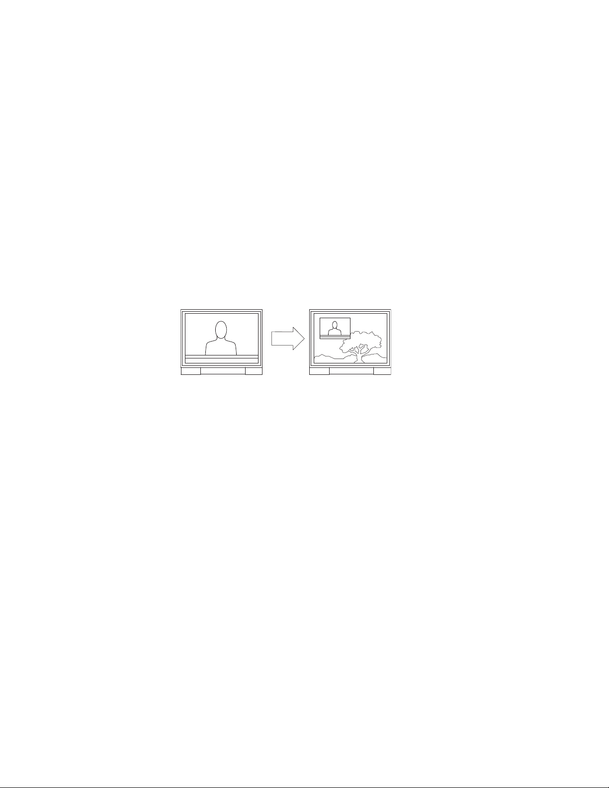
The DVE option allows one background bus (audio and video) and its
selected upstream keys to be in a squeeze window with another background bus and its selected upstream keys serving as the background. The
AUX bus is fully utilized with this release.
A DVE effect is entered by selecting the desired effect and pressing
While the DVE effect is active, a variety of audio/video transitions may be
performed (also by pressing
of the available exit modes and pressing
When a DVE effect is active, the content of the squeeze window is the PGM
bus. The content of the background is the AUX bus.
An example is shown in Figure 1.
Figure 1. Example of a Maestro DVE Effect
Transition type (cut, fade, or wipe) and transition speed are selected using
the control panel.
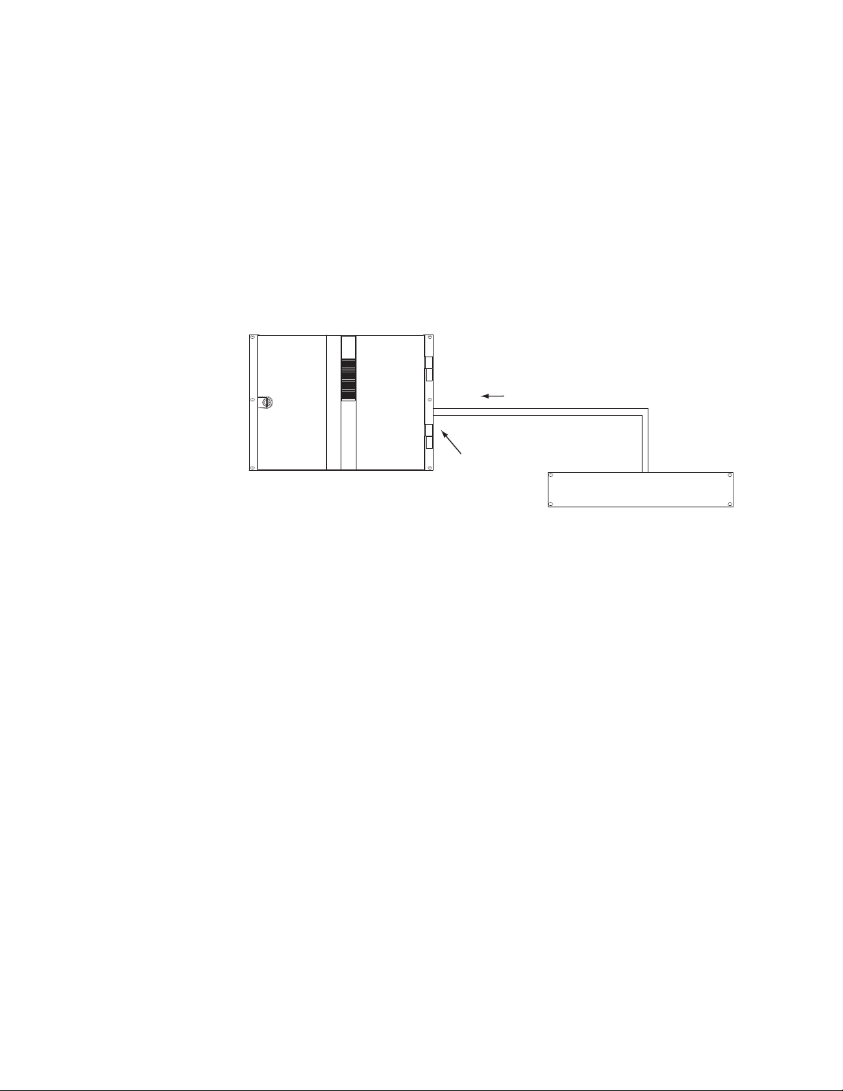
The DVE hardware consists of a mezzannine board that mounts on the
main processor board (see Figure 2), and, in some cases, an AES-to-MADI
converter.
Take). A DVE effect is exited by selecting one
Take.
Take.
8 Maestro Release Notes
Page 9
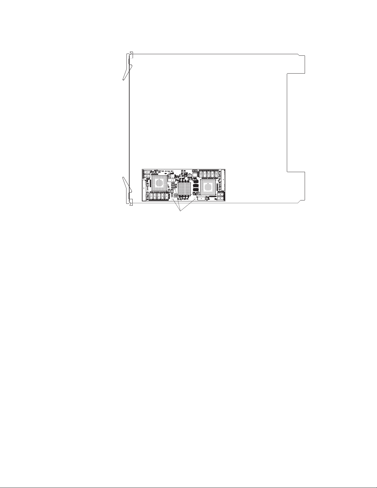
Figure 2. Top View of Processor Showing DVE Mezzannine Board
Screws
DVE
Screws
The DVE option requires three background video sources (BGA, BGB, and
BGC).
The DVE option also requires three background audio sources:
• If the Maestro will use embedded audio, no additional hardware is
required for DVE operation.
• If the system includes a Grass Valley Apex audio router, no additional
hardware is required for DVE operation since Apex includes AESMADI conversion as a standard feature.
• If the Maestro will use AES audio inputs, then an optional 1 RU AES to
MADI Converter unit must be used to provide the third background
audio source. The planner should specifiy “SON-AU2MADI” (Sonata
AES 75 ohm unbalanced to MADI) or “SON-AB2MADI” (Sonata AES
110 ohm balanced to MADI) units. When these Sonata converters are
installed, the corresponding AES inputs on the Maestro rear panel are
not used.
For DVE installation and operating instructions, please refer to Field Modification Note 075078902, DVE Option.
For Sonata installation instructions, please refer to publication 071860901,
Sonata Series Planning and Installation Manual.
Maestro Release Notes 9
Page 10
Version 1.400
General Purpose “Transition” Input/Output
With this release, the GPIO connector on the Maestro rear panel can be used
to receive an “Action: Transition” signal from a controlling external device
(Figure 3), or to transmit an “Action: Transition in Progress” signal to a controlled external device (Figure 4).
Maestro Controlled by External Device
Figure 3. GPI Connections to External Controlling Device
Maestro
1A
1B
GPI Port/Photocoupler
Note 1
Connections between Maestro
GPIO Connector and controlling
external device are bipolar.
Note 2
Maximum current through Maestro photocoupler = 4.25 mA
"High" range for photocoupler = 3-10 V
See Notes
"Transition" signal
Controlling external device
TTL
Trigger
Port
10 Maestro Release Notes
Page 11

Maestro Controlling External Device
When used to control an external device, all present Maestro systems
require installation of a leakage-current swamping resistor in the GPO circuit. This resistor is used to prevent leakage current from reaching the
external device when the Maestro GPO relay is open. The resistor is always
placed accross the input relay of the external device.
Figure 4 and Figure 5 show examples of connections to controlled external
devices containing a small mechanical or solid-state relay, along with a suggested location and value for the swamping resistor. A supply voltage
greater than +5 V can be used (up to + 10 V), but in that case the power
rating of the resistor would need to be increased accordingly.
Figure 4. GPO Connections to External Controlled Device (Example1)
Maestro
"Transition in Progress" signal
1A
1B
GPO Port/Relay
See Notes
General Purpose “Transition” Input/Output
220 ohm
1/8 W
resistor
Note 1
Connections between Maestro
GPIO Connector and controlled
external device are bipolar.
Note 2
Maximum current through Maestro relay = 250 mA
Maximum voltage for relay = 10 V
Controlled external device
Figure 5. GPO Connections to External Controlled Device (Example 2)
Maestro
220 ohm
resistor
+5 V
Note 1
Connections between Maestro
GPIO Connector and controlled
external device are bipolar.
Note 2
Maximum current through Maestro relay = 250 mA
Maximum voltage for relay = 10 V
"Transition in Progress" signal
1A
1B
GPO Port/Relay
See Notes
Controlled external device
+5 V
1/8 W
Maestro Release Notes 11
Page 12

Version 1.400
It is also possible for one Maestro to control another. See Figure 6.
Figure 6. Maestro-to-Maestro GPIO Connections
Controlling Maestro
"Transition in Progress" signal
1A
1B
GPO Port/Relay
See Notes
Note 1
Connections between Maestro
GPIO Connector and controlled
external device are bipolar.
Note 2
Maximum current through Maestro relay = 250 mA
Maximum voltage for relay = 10 V
+
5 V
-
External
power
Controlled Maestro
See Notes
"Transition" signal
220 ohm
resistor
1/8 W
1A
1B
GPI Port/Photocoupler
Note 3
Maximum current through Maestro photocoupler = 4.25 mA
"High" range for photocoupler = 3-10 V
The controlling Maestro would be configured to send a“Transition in
Progress” signal (i.e., by closing a GPO port relay) to indicate that the
Maestro has initiated a Take.
The controlled Maestro would be configured to accept a “Transition” signal
and respond by executing a Take command.
For pinouts of the GPIO connector, refer to the “GPIO” columns in Tab le 3.
For a representative schematic of the GPIO port, refer to Figure 7.
12 Maestro Release Notes
Page 13

General Purpose “Transition” Input/Output
V
CC
From
Maestro
logic
GPIO
rear panel
connector
To
Maestro
logic
V
OUT
ON = 3-10 V, 4.25 mA max.
Input photocoupler
NEC PS2705-1
Maximum current through relay = 250 mA
Maximum voltage for relay = 10 V
Output relay
International Rectifier PVG613
2.2 K, 0.1 W
B
A
10K
Note: To prevent a ground loop, use pins
"A" and "B" only w
hen con
necting M
aestro
to an external device. Do not connect a third
conductor as a com
m
on ground path (e.g.,
do not connect the connector shields).
Table 3. Maestro Rear Panel, GPIO 44-pin ConnectorPinouts
Shielded 44-Pin D;
socket contacts
D-44 Female
Pin 1
Pin 15
Pin 16
Pin 30
Pin 29
Pin 44
Pin GPIO Pin GPIO
1 1A 23 10A
2 1B 24 10B
3 2A 25 GND
4 2B 26 11A
5 GND 27 11B
6 3A 28 12A
7 3B 29 12B
8 4A 30 GND
9 4B 31 13A
10 GND 32 13B
11 5A 33 14A
12 5B 34 14B
13 6A 35 GND
14 6B 36 15A
15 GND 37 15B
16 7A 38 16A
17 7B 39 16B
18 8A 40 GND
19 8B 41 NC
20 GND 42 NC
21 9A 43 LTC RX IN+
22 9B 44 LTC RX IN–
Figure 7. GPIO Port Circuitry
Maestro Release Notes 13
Page 14

Version 1.400
Maestro Configuration
The GPIO Definition table is used to configure the GPIO ports on the rear
panel of the Maestro. The table is located in the Input/Output Sets group
of the Maestro Configurator (“4th Step”). When the GPIO Definition table
is first opened, the editor will open a set panel. Create a name for the GPIO
table, select an Input Set, then select “New.” (The table is assigned to a
Maestro channel using the Channel Setup table.)
External Device Control of Maestro (Action: Transition)
In this application, an external device can send a Transition (Take)
command to the Maestro. See Figure 8.
Figure 8. GPIO Definition table for “Transition” Trigger to Maestro
Device Type
For this application, select “MaestroGPI.”
Identifier
The numbers in this column refer to the 16 ports on the GPIO connector.
Any port from 1 to 16 can be selected in any order.
Sub System
Select “Action.”
Purpose
“Transition” is the only choice when “MaestroGPI is the device type.
Trigger Type
Trigger Type can be “Level” or “Pulse.” If Pulse, the input pulse duration
must be one field or more.
14 Maestro Release Notes
Page 15

General Purpose “Transition” Input/Output
Trigger Duration
This column is not used in this application.
Trigger Sense
Select “High” if the external device is normally low and will send between
3 and 10 V to assert “Transition.” Select “Low” if the external device is normally high and will present zero V to assert “Transition.”
When finished configuring the table, select “Apply” or “OK.” The Name of
the GPIO Definition set will now appear in the set panel. The set is assigned
to the appropriate Maestro channel (Processor) using the Channel Setup
table.
Maestro Control of External Device (Action: Transition in Progress)
In this application, Maestro can send a Transition in Progress signal to an
external device. See Figure 9.
Figure 9. GPIO Definition table for “Transition” Trigger to Maestro
Device Type
For this application, select “MaestroGPO.”
Identifier
The numbers in this column refer to the 16 ports on the GPIO connector.
Any port from 1 to 16 can be selected in any order.
Sub System
Select “Action.”
Maestro Release Notes 15
Page 16

Version 1.400
Purpose
“Transition in Progress” is the only choice when “MaestroGPO” is the
device type.
Trigger Type
“Level” is the only choice when “MaestroGPO” is the device type. When a
transition begins, the GPIO contact will go to the state selected in the
Trigger Sense column (described below).
Trigger Duration
This column is not used in this application.
Trigger Sense
Selections are:
•High - close the contact when a transition begins and open when the
transition is complete), or
•Low - open the contact when a transition begins and close when the tran-
sition is complete.
When finished configuring the table, select “Apply” or “OK.” The Name of
the GPIO Definition set will now appear in the set panel. The set is assigned
to the appropriate Maestro channel (Processor) using the Channel Setup
table.
16 Maestro Release Notes
Page 17

Software Upgrade Procedure
CAUTION Portions of this procedure will interrupt video and audio signals passing
through the system. Users of this equipment should consult with Grass
Valley Technical Support personnel before proceeding.
Maestro Deployment PC
Note In some installations, the “deployment PC” will be the same as the GUI PC.
Requirements
• A period of time where the Maestro system can be taken off-line (externally bypassed).
• Windows XP Service Pack 2.
• In order to upgrade the Maestro software, the Maestro configuration
computer will need access to the installation CD or downloaded installation files.
Software Upgrade Procedure
• The configuration from the existing operational Maestro system will be
used to complete the Maestro upgrade.
Checking the Boot ROM Versions
Version 1.4 requires the Processor and hardware control panel boot ROMs
to be current. (Older versions of the boot ROMs will operate under v1.4 but
this would require the deployment PC and system software to be active at
all times.)
1. In the Maestro Deployment Control Center window, select the
Processor with the boot ROM you wish to check. The row for the
selected Processor will have a dark background.
2. Select the Telnet button.
Note Only one Telnet session to a Processsor can be open at a time.
3. In the Telnet window, type:
Maestro Release Notes 17
Page 18

Version 1.400
d 0x50004710 [Enter]
If the Boot ROM is current, the first two rows of the display will indicate
a date of December 14, 2006:
50004710: 576f 726b 7335 2e35 2e31 0044 6563 2031 *Works5.5.1.Dec 1
50004720: 3420 3230 3036 2c20 3037 3a32 383a 3037 *4 2006
• If the Boot ROM version checks OK, go to Step 4 below.
• If you see an older date, or no date at all, the Boot ROM should be
updated. Contact Grass Valley Technical Support for update
instructions.
4. If there is another Processor (channel) in the system, repeat Step 1
above and following. If not, go to Step 5.
5. In the Maestro Deployment Control Center window, select the control
panel with the boot ROM you wish to check.
For a hardware control panel, this will actually be a CP Panel Server
board. For a GUI control panel, this will actually be a PCI Panel Server
board.
6. Select the Telnet button.
Note Only one Telnet session to a Panel Server can be open at a time.
7. In the Telnet window, type:
d 0x50004710 [Enter]
, 07:28:07*
*
If the Boot ROM is current, the first two rows of the display will indicate
a date of December 14, 2006:
50004710: 576f 726b 7335 2e35 2e31 0044 6563 2031 *Works5.5.1.Dec 1
50004720: 3420 3230 3036 2c20 3037 3a32 383a 3037 *4 2006
• If the Boot ROM version checks OK, go to Step 8 below.
• If you see an older date, or no date at all, the Boot ROM should be
updated. Contact Technical Support for update instructions.
8. If there is another control panel in the system, repeat Step 5 above and
following. If all boot ROMs check OK, go to Installing the Maestro
Software Package below.
, 07:28:07*
*
18 Maestro Release Notes
Page 19

Installing the Maestro Software Package
Perform this procedure only after checking the Boot ROM versions.
Note It is recommended that all default values be used during the installation.
1. Make a copy of the current configuration set:
a. Launch the Maestro Configuration Editor by going to “Start > All
Programs > Thomson > Maestro Configuration Editor.”
b. Use “File > Open” to open the current configuration set.
c. Use “File > Save As” to create a copy of the set.
As a suggestion, add “v13” to the name.
d. Use “File > Save As” again to create another copy of the set.
As a suggestion, add “v1400” to the name.
e. Close all Maestro applications.
2. The previous version of Maestro must be uninstalled:
Software Upgrade Procedure
CAUTION If you are uninstalling v1.3 software, you must use the Administrator account
(login). If you are uninstalling v1.2 or prior software, you must use the
account (login) used when that software was installed.
a. Using the Windows Control Panel, select Add or Remove
Programs.
b. Remove the Maestro Software Package.
This will not remove user data.
c. Close the Windows Control Panel.
3. Insert the new Maestro software CD.
A popup will appear that asks if the install should continue. Click on
Next. Go to Step 4.
If the installation does not automatically start, the process will have to
be started manually:
a. Select Start > Run.
A window similar to that shown in Figure 10 should appear.
Maestro Release Notes 19
Page 20

Version 1.400
Figure 10. Run Dialog Box
b. Enter “D:\setup.exe” where D: is the CD Drive.
c. Click the OK button.
A popup will appear that asks if the install should continue; select
Go to Step 4.
4. A popup will indicate the default destination folder. Select Next.
5. For Setup Type, select Complete.
6. When the “Ready to Install” menu appears, select Install.
The window shown in Figure 11 will appear.
Next.
20 Maestro Release Notes
Page 21

Software Upgrade Procedure
Figure 11. Installing Maestro Software Package
When this step is complete, the window shown in Figure 12 will appear.
Figure 12. Maestro Software Package Installation Complete
7. Select Finish.
Installation of the Maestro Software Package on the PC is now complete.
Note If the installation fails to complete and you see the error message “Error 1001
-- the specified service already exists,” you may need to manually remove the
Maestro Jupiter Router Service software. Refer to Manually Removing the
Maestro Jupiter Router Service Software on page 22.
8. Proceed to Re-compiling the Configuration File on page 23.
Maestro Release Notes 21
Page 22

Version 1.400
Manually Removing the Maestro Jupiter Router Service Software
Perform this procedure only if you see the error message “Error 1001 -- the
specified service already exists” referred to in the Note on page 21.
1. Go to “Control Panel > Adminstrative Tools > Services.”
2. Right click on “MaestroJupiterRouterService” and select Stop.
3. Go to “Start > Run” and enter “regedit.”
4. Go to “HKEY_LOCAL_MACHINE > SYSTEM > CurrentControlSet >
Services.”
5. Highlight “MaestroJupiterRouterService.” Right click and delete this
item.
6. Close all windows and reboot. Repeat Step 1 above and confirm that
MaestroJupiterRouterService is not listed.
7. Proceed with re-installation of the new software, starting with Step 3 on
page 19.
22 Maestro Release Notes
Page 23

Re-compiling the Configuration File
This step is required because changes have be been made to the structure
of the Monitor Follow configuration table
1. Launch the Maestro Configuration Editor by going to “Start > All
Programs > Thomson > Maestro Configuration Editor.”
2. Select the Maestro configuration set to be re-compiled by going to “File
> Open > Thomson” and selecting the set.
This should be the configuration set created for v1.400 use (Step d on
page 19).
3. If the system displays a Validation Report, you must check the
indicated table(s) and make corrections as indicated.
You can use the links in the Description column to display the table(s).
4. Save the configuration file.
5. Compile the file by going to “File > Compile Channel Data.”
Software Upgrade Procedure
6. Proceed to Updating the System Configuration and Software below.
Maestro Release Notes 23
Page 24

Version 1.400
Updating the System Configuration and Software
1. Launch the Maestro Deployment control center by selecting “Start > All
Programs > Thomson > Maestro Deployment Center.”
A Maestro Deployment Control Center window similar to that shown
in Figure 13 should appear.
Figure 13. Maestro Deployment Control Center (example)
2. (Optional) Select Show Log to provide detailed monitoring of the update
process.
3. In the Configuration box:
a. Verify that the Folder field has the correct path to the Maestro
configuration directory. (Default = C:\Thomson)
b. In the “File:” drop down field, select the Maestro configuration set
to be activated.
This should be the configuration set updated and compiled for
v1.400 use (Step 5 on page 23).
24 Maestro Release Notes
Page 25

Software Upgrade Procedure
c. Click the Update Only button.
This will update the contents of the “Pending>>” rows in the Board
Configuration and Active Configuration columns.
The Configuration box contains two buttons:
and Apply
Update Only - Activates the configuration and downloads it to the
boards, but does not apply it as the running configuration.
Update and apply - Activates the configuration, downloads it to the
boards and applies it as the running configuration.
CAUTION The following step will interrupt the video and audio signals passing through
the system for about 1 minute.
d. Click the Update and Apply button.
The pending Configuration files will load and execute.
This will also update the contents of the “Running>>” rows in the
Board Configuration and Active Configuration columns.
4. In the Software Application box:
a. The “Folder” field should indicate “C:\MaestroEmbedded.”
b. In the Frame Processor Tar File Name field:
--For LTC systems (those using Linear Time Code) select
“MaestroMC_1.400.2537.887.LTC.tar.” (When used, LTC is connected to pins 43 and 44 of the GPIO connector on the rear panel.)
.
Update Only and Update
--For VITC systems (those using Vertical Interval Time Code) select
“MaestroMC_1.400.2537.887.VITC.tar.”
c. In the Control Panel Tar File Name, field, select
“MaestroCP_1.400.2537.887.tar.”
5. Click the Select All button (lower right corner of menu).
Alternatively, each board can be updated independently by clicking on
the "Board Name" field or all at the same time by using the "Select All"
button.
6. In the Software Application box:
a. Click the Update Only Button.
This will update the contents of the “Pending>>” rows in the
Ver s io n co l um n s.
CAUTION The following step will interrupt the video and audio signals passing through
the system for about 1 minute.
Maestro Release Notes 25
Page 26

Version 1.400
b. Click the Update and Apply Button.
The pending software files will load and execute.
This will also update the contents of the “Running>>” rows in the
Ver s io n co l um n s.
7. Verify that the new Configuration and Application versions are
“Running” as seen in Figure 14.
Figure 14. Maestro Deployment Control Center Software Version Status
8. Proceed to Checking the GUI Control Panel for Proper LAN Settings on
page 27.
26 Maestro Release Notes
Page 27

Software Upgrade Procedure
Checking the GUI Control Panel for Proper LAN Settings
The “Panel Server IP” address and the "Local IP” address for the Maestro
GUI must now use control LAN addresses only. In previous releases, the
GUI application would connect and run over the facility LAN; this is no
longer possible with version 1.400.
The following steps should be taken to ensure that the GUI application is
set for the correct addresses:
1. With Maestro’s GUI up and running, press the “Settings” button. This
will open the Application Settings window.
2. Double-click (or select and press Alter) the “Panel Server IP” setting.
3. Specify the control LAN address of the Panel Server card associated
with the GUI.
This will switch the view back to the first Application Settings window.
To look up the GUI control LAN address, go to “Maestro Configuration
Editor > Network Description Table.” Then check the Board Type
“GUI” row and the “Control LAN IP Address” column.
4. Double-click (or select and press Alter) the “Local IP” setting.
5. Select the control LAN address of the PC associated with the GUI.
This will switch the view back to the first Application Settings window.
To look up the PC control LAN address, go to “Start > Control Panel >
Network Connections.” Double-click on the the card used for the
control LAN. Then go to Properties > Internet Protocol > Properties. .
6. Close the Application Settings window. The GUI should then connect
and work properly.
Note If you continue to have difficulty with this change, please contact Technical
Support.
7. Proceed to Updating FPGAs/CPLDs on page 28.
Maestro Release Notes 27
Page 28

Version 1.400
Updating FPGAs/CPLDs
(FPGA = Field Programmable Gate Array. CPLD = Complex Programmable Logic Device.)
1. Updating FPGAs/CPLDs on the Processor board(s):
Note Some of the FPGAs on the Processor are updated using the Software Version
Update and Apply procedure described above. The remaining FPGAs on the
Processor are updated using the procedure below.
a. In the board Status section of the Maestro Deployment control
center, select the Processor to update.
b. Right-click on the “Running” FPGA field for this Processor. See
Figure 15.
Figure 15. “Running” FPGA Field
This will display the FPGA/CPLD update menu. See Figure 16.
28 Maestro Release Notes
Page 29

Figure 16. FPGA/CPLD Update Menu (Example for Processor)
Software Upgrade Procedure
This menu shows the names of all FPGAs/CPLDs on the Processor
and the version number of the gateware now running (“Loaded”)
in each device. Certain of the FPGA-type components and all of the
CPLD-type components can be updated using this menu, and if a
newer (“current”) version of gateware is available for those components the menu will indicate the new version number and display a
check box.
Note A Current version may have a smaller number than the corresponding Loaded
version.
c. Check the “Select All” box.
Note Do not check “Gennum A” or “Gennum B” if no DVE board is installed. Doing
so will cause the update to fail.
d. Select Update.
You will be asked to confirm the update.
CAUTION The following step will interrupt the video and audio signals passing through
the system.
e. Answer Yes.
f. From this point there are two possibilites:
• A popup will show that the Processor update was successful.
Repeat Step 1 above if another Processor is present. Otherwise,
go to Step 2 below.
Maestro Release Notes 29
Page 30

Version 1.400
• An error message may indicate that the “physical JTAG chain is
broken.” If this message appears, the FPGAs/CPLDs on the Processor cannot be updated. Discontinue the v1.400 installation
and contact Technical Support.
2. Updating FPGAs/CPLDs on the hardware control panel(s):
a. In the board Status section of the screen, select the hardware control
panel to update.
b. Right-click on the FPGA field for this control panel.
This will display the FPGA/CPLD update menu. See Figure 16.
Figure 17. FPGA/CPLD Update Menu (Example for Hardware Control Panel)
This menu shows the names of all FPGAs/CPLDs on the control
panel and the version number of the gateware now running
(“loaded”) in each device. Certain FPGA-type components and all
of the CPLD-type components can be updated using this menu, and
if a newer (“current”) version of gateware is available for those
components the menu will indicate the new version number and
display a check box.
c. Check the “Select All” box.
d. Select Update.
You will be asked to confirm the update.
CAUTION The following step will cause the control panel to become inoperative while
the update is in progress.
e. Answer Yes.
f. From this point there are several possibilites:
30 Maestro Release Notes
Page 31

Software Upgrade Procedure
• A popup will show that the control panel update was suc-
cessful. Repeat Step 2 above if another control panel is present.
When all FPGAs/CPLDs have been updated, the v1.400
upgrade is complete.
• An error message may indicate that the “physical JTAG chain is
broken.” The CP Panel Server board, which is located within the
control panel, may need to be replaced. This procedure is
described in Field Modification Note 075079500, Maestro Pro-
cessor Backup Battery, CP Server, and CP FPGA Upgrade. For more
information, contact Technical Support.
• An error messsage may indicate that a module (sub panel) on
the hardware control panel “reported an incorrect module ID.”
In this case, refer to Field Modification Note 075079500, Maestro
Processor Backup Battery, CP Server, and CP FPGA Upgrade.
Maestro Release Notes 31
Page 32

Version 1.400
32 Maestro Release Notes
 Loading...