

Page 1
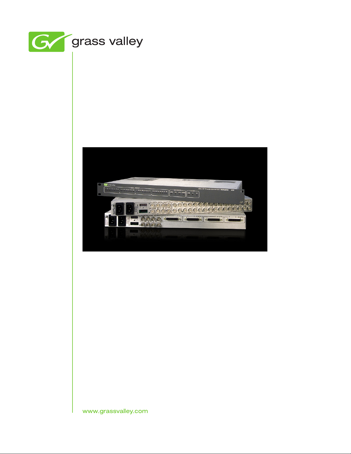
Sonata Series
MADI - AES/Analog Audio Converters
Planning and Installation Manual
071860903
MARCH 2010
Page 2
Affiliate with the N.V. KEMA in The Netherlands
CERTIFICATE
Certificate Number: 510040.001
The Quality System of:
Thomson Inc, and it’s wordwide Grass Valley division affiliates DBA
GRASS VALLEY
Headquarters
400 Providence Mine Rd
Nevada City, CA 95959
United States
15655 SW Greystone Ct.
Beaverton, OR 97006
United States
10 Presidential Way
Suite 300
Woburn, MA 01801
United States
Kapittelweg 10
4827 HG Breda
The Nederlands
7140 Baymeadows Way
Ste 101
Jacksonville, FL 32256
United States
2300 So. Decker Lake Blvd.
Salt Lake City, UT 84119
United States
Rue du Clos Courtel
CS 31719
35517 Cesson-Sevigné Cedex
France
1 rue de l’Hautil
Z.I. des Boutries BP 150
78702 Conflans-Sainte
Honorine Cedex
France
Technopole Brest-Iroise
Site de la Pointe du Diable
CS 73808
29238 Brest Cedex 3
France
40 Rue de Bray
2 Rue des Landelles
35510 Cesson Sevigné
France
Spinnereistrasse 5
CH-5300 Turgi
Switzerland
Brunnenweg 9
D-64331 Weiterstadt
Germany
Carl-Benz-Strasse 6-8
67105 Schifferstadt
Germany
Including its implementation, meets the requirements of the standard:
ISO 9001:2008
Scope:
The design, manufacture and support of video and audio hardware and software products and
related systems
.
This Certificate is valid until: June 14, 2012
This Certificate is valid as of: June 14, 2009
Certified for the first time: June 14, 2000
H. Pierre Sallé
President
KEMA-Registered Quality
The method of operation for quality certification is defined in the KEMA General Terms
And Conditions For Quality And Environmental Management Systems Certifications.
Integral publication of this certificate is allowed.
KEMA-Registered Quality, Inc.
4377 County Line Road
Chalfont, PA 18914
Ph: (215)997-4519
Fax: (215)997-3809
CRT 001 073004
ccredited By:
ANAB
A
Page 3

Sonata Series
MADI - AES/Analog Audio Converters
Planning and Installation Manual
071860903
MARCH 2010
Page 4
Contacting Grass Valley
International
Support Centers
Local Support
Centers
(available
during normal
business hours)
France
24 x 7
Australia and New Zealand: +61 1300 721 495 Central/South America: +55 11 5509 3443
Middle East: +971 4 299 64 40 Near East and Africa: +800 8080 2020 or +33 1 48 25 20 20
Europe
+800 8080 2020 or +33 1 48 25 20 20
Hong Kong, Taiwan, Korea, Macau: +852 2531 3058 Indian Subcontinent: +91 22 24933476
Asia
Southeast Asia/Malaysia: +603 7805 3884 Southeast Asia/Singapore: +65 6379 1313
China: +861 0660 159 450 Japan: +81 3 5484 6868
Belarus, Russia, Tadzikistan, Ukraine, Uzbekistan: +7 095 2580924 225 Switzerland: +41 1 487 80 02
S. Europe/Italy-Roma: +39 06 87 20 35 28 -Milan: +39 02 48 41 46 58 S. Europe/Spain: +34 91 512 03 50
Benelux/Belgium: +32 (0) 2 334 90 30 Benelux/Netherlands: +31 (0) 35 62 38 42 1 N. Europe: +45 45 96 88 70
Germany, Austria, Eastern Europe: +49 6150 104 444 UK, Ireland, Israel: +44 118 923 0499
Copyright © Thomson, Inc. All rights reserved.
This product may be covered by one or more U.S. and foreign patents.
United States/Canada
24 x 7
+1 800 547 8949 or +1 530 478 4148
Grass Valley Web Site
The www.grassvalley.com web site offers the following:
Online User Documentation — Current versions of product catalogs, brochures,
data sheets, ordering guides, planning guides, manuals, and release notes
in .pdf format can be downloaded.
FAQ Database — Solutions to problems and troubleshooting efforts can be
found by searching our Frequently Asked Questions (FAQ) database.
Software Downloads — Download software updates, drivers, and patches.
4 Sonata Series — Planning and Installation Manual
Page 5

Contents
Preface. . . . . . . . . . . . . . . . . . . . . . . . . . . . . . . . . . . . . . . . . . . . . . . . . . . . . . . . . . . . . . . . . . . . . 7
Safety Summary. . . . . . . . . . . . . . . . . . . . . . . . . . . . . . . . . . . . . . . . . . . . . . . . . . . . . . . . . . 9
Regulatory Notices . . . . . . . . . . . . . . . . . . . . . . . . . . . . . . . . . . . . . . . . . . . . . . . . . . . . . . 21
About This Manual . . . . . . . . . . . . . . . . . . . . . . . . . . . . . . . . . . . . . . . . . . . . . . . . . . . . . 7
Additional Documentation . . . . . . . . . . . . . . . . . . . . . . . . . . . . . . . . . . . . . . . . . . . . 7
Safety Terms and Symbols. . . . . . . . . . . . . . . . . . . . . . . . . . . . . . . . . . . . . . . . . . . . . . . 9
Terms in This Manual. . . . . . . . . . . . . . . . . . . . . . . . . . . . . . . . . . . . . . . . . . . . . . . . . 9
Terms on the Product . . . . . . . . . . . . . . . . . . . . . . . . . . . . . . . . . . . . . . . . . . . . . . . . . 9
Symbols on the Product . . . . . . . . . . . . . . . . . . . . . . . . . . . . . . . . . . . . . . . . . . . . . . 10
Warnings . . . . . . . . . . . . . . . . . . . . . . . . . . . . . . . . . . . . . . . . . . . . . . . . . . . . . . . . . . . . 10
Cautions . . . . . . . . . . . . . . . . . . . . . . . . . . . . . . . . . . . . . . . . . . . . . . . . . . . . . . . . . . . . . 11
Certifications and Compliances . . . . . . . . . . . . . . . . . . . . . . . . . . . . . . . . . . . . . . . . . 21
FCC Emission Control . . . . . . . . . . . . . . . . . . . . . . . . . . . . . . . . . . . . . . . . . . . . . . . 21
Canadian EMC Notice of Compliance . . . . . . . . . . . . . . . . . . . . . . . . . . . . . . . . . . 21
EN55022 Class A Warning . . . . . . . . . . . . . . . . . . . . . . . . . . . . . . . . . . . . . . . . . . . . 21
Canadian Certified Power Cords . . . . . . . . . . . . . . . . . . . . . . . . . . . . . . . . . . . . . . 22
Canadian Certified AC Adapter . . . . . . . . . . . . . . . . . . . . . . . . . . . . . . . . . . . . . . . 22
Laser Compliance . . . . . . . . . . . . . . . . . . . . . . . . . . . . . . . . . . . . . . . . . . . . . . . . . . . 22
Laser Safety Requirements . . . . . . . . . . . . . . . . . . . . . . . . . . . . . . . . . . . . . . . . . . 22
Laser Safety. . . . . . . . . . . . . . . . . . . . . . . . . . . . . . . . . . . . . . . . . . . . . . . . . . . . . . . 22
FCC Emission Limits. . . . . . . . . . . . . . . . . . . . . . . . . . . . . . . . . . . . . . . . . . . . . . . 23
Certifications: . . . . . . . . . . . . . . . . . . . . . . . . . . . . . . . . . . . . . . . . . . . . . . . . . . . . . . . 24
Section 1 — Introduction. . . . . . . . . . . . . . . . . . . . . . . . . . . . . . . . . . . . . . . . . . . . . . . . 25
The Sonata Family. . . . . . . . . . . . . . . . . . . . . . . . . . . . . . . . . . . . . . . . . . . . . . . . . . . . . 25
Sonata MADI Converters Features. . . . . . . . . . . . . . . . . . . . . . . . . . . . . . . . . . . . . . . 26
Sonata AES-to-MADI Converters. . . . . . . . . . . . . . . . . . . . . . . . . . . . . . . . . . . . . . . . 28
Sonata MADI-to-AES Converters. . . . . . . . . . . . . . . . . . . . . . . . . . . . . . . . . . . . . . . . 29
Sonata Analog-to-MADI (AM) and MADI-to-Analog (MA) Converters . . . . . . . 30
Section 2 — Planning Guide . . . . . . . . . . . . . . . . . . . . . . . . . . . . . . . . . . . . . . . . . . . . 31
Quick Check List . . . . . . . . . . . . . . . . . . . . . . . . . . . . . . . . . . . . . . . . . . . . . . . . . . . . . . 31
The MADI Standard . . . . . . . . . . . . . . . . . . . . . . . . . . . . . . . . . . . . . . . . . . . . . . . . . . 31
Sample-Rate Conversion . . . . . . . . . . . . . . . . . . . . . . . . . . . . . . . . . . . . . . . . . . . . . . . 32
Reference Considerations . . . . . . . . . . . . . . . . . . . . . . . . . . . . . . . . . . . . . . . . . . . . . . 33
Dolby E and Dolby Digital signals . . . . . . . . . . . . . . . . . . . . . . . . . . . . . . . . . . . . . . . 34
Stand-Alone Use . . . . . . . . . . . . . . . . . . . . . . . . . . . . . . . . . . . . . . . . . . . . . . . . . . . . . . 34
Interfacing to Maestro . . . . . . . . . . . . . . . . . . . . . . . . . . . . . . . . . . . . . . . . . . . . . . . . . 34
Sonata to Maestro Mapping Tables. . . . . . . . . . . . . . . . . . . . . . . . . . . . . . . . . . . 39
Interfacing to Apex . . . . . . . . . . . . . . . . . . . . . . . . . . . . . . . . . . . . . . . . . . . . . . . . . . . . 42
MADI Input Mapping. . . . . . . . . . . . . . . . . . . . . . . . . . . . . . . . . . . . . . . . . . . . . . . . 42
Sonata to Apex Mapping Tables . . . . . . . . . . . . . . . . . . . . . . . . . . . . . . . . . . . . . 42
Sonata Series — Planning and Installation Manual 5
Page 6

Output Mapping for the Sonata MADI to AES Outputs from Apex. . . . . . . . . 45
Apex to Sonata Mapping Tables . . . . . . . . . . . . . . . . . . . . . . . . . . . . . . . . . . . . . 46
Locked Stereo Mode . . . . . . . . . . . . . . . . . . . . . . . . . . . . . . . . . . . . . . . . . . . . . . . 47
Single-Channel Mono Mode. . . . . . . . . . . . . . . . . . . . . . . . . . . . . . . . . . . . . . . . . 48
Ordering Information. . . . . . . . . . . . . . . . . . . . . . . . . . . . . . . . . . . . . . . . . . . . . . . . . . 49
Section 3 — Installation. . . . . . . . . . . . . . . . . . . . . . . . . . . . . . . . . . . . . . . . . . . . . . . . . 51
Sonata Connector Mapping Tables . . . . . . . . . . . . . . . . . . . . . . . . . . . . . . . . . . . 52
DIP Switches . . . . . . . . . . . . . . . . . . . . . . . . . . . . . . . . . . . . . . . . . . . . . . . . . . . . . . . . . 55
Digital . . . . . . . . . . . . . . . . . . . . . . . . . . . . . . . . . . . . . . . . . . . . . . . . . . . . . . . . . . . 55
Analog . . . . . . . . . . . . . . . . . . . . . . . . . . . . . . . . . . . . . . . . . . . . . . . . . . . . . . . . . . . 56
Maestro Configuration for Sonata Installation . . . . . . . . . . . . . . . . . . . . . . . . . . . . . 58
Section 4 — Troubleshooting . . . . . . . . . . . . . . . . . . . . . . . . . . . . . . . . . . . . . . . . . . . 59
LEDs . . . . . . . . . . . . . . . . . . . . . . . . . . . . . . . . . . . . . . . . . . . . . . . . . . . . . . . . . . . . . . . . 59
Front Panel . . . . . . . . . . . . . . . . . . . . . . . . . . . . . . . . . . . . . . . . . . . . . . . . . . . . . . . . . 59
Signal Present LEDs . . . . . . . . . . . . . . . . . . . . . . . . . . . . . . . . . . . . . . . . . . . . . . . . . 59
Reference LEDs . . . . . . . . . . . . . . . . . . . . . . . . . . . . . . . . . . . . . . . . . . . . . . . . . . . . . 60
Appendix A — Specifications . . . . . . . . . . . . . . . . . . . . . . . . . . . . . . . . . . . . . . . . . . . 61
Mechanical and Power . . . . . . . . . . . . . . . . . . . . . . . . . . . . . . . . . . . . . . . . . . . . . . . . . 61
Environmental . . . . . . . . . . . . . . . . . . . . . . . . . . . . . . . . . . . . . . . . . . . . . . . . . . . . . . . . 61
Inputs . . . . . . . . . . . . . . . . . . . . . . . . . . . . . . . . . . . . . . . . . . . . . . . . . . . . . . . . . . . . . . . 62
Outputs. . . . . . . . . . . . . . . . . . . . . . . . . . . . . . . . . . . . . . . . . . . . . . . . . . . . . . . . . . . . . . 63
MADI . . . . . . . . . . . . . . . . . . . . . . . . . . . . . . . . . . . . . . . . . . . . . . . . . . . . . . . . . . . . . . . 64
Reference . . . . . . . . . . . . . . . . . . . . . . . . . . . . . . . . . . . . . . . . . . . . . . . . . . . . . . . . . . . . 64
Index . . . . . . . . . . . . . . . . . . . . . . . . . . . . . . . . . . . . . . . . . . . . . . . . . . . . . . . . . . . . . . . . . . . . . . 67
Sonata Series — Planning and Installation Manual 6
Page 7

Preface
About This Manual
This manual provides introductory and system planning information for
the Sonata Series of MADI - AES/Analog Audio Converters.
Additional Documentation
A electronic copy of the manual is normally provided with the system.
Individual manuals may be ordered by
information, see page 4.
Electronic copies of other routing products documents are available on the
following documentation CDs:
Contacting Grass Valley. For contact
CD 0718130xx. 7000/7500 control system, Acappella, Apex, Concerto,
Encore, JEP-100, Jupiter VM-3000, Jupiter CM-4000, NetCentral, Net
Config, Omni, OUI42, Prelude, selected routing protocols, and Trinix
documentation.
CD 0718517xx. Maestro Master Control System documentation.
Most of these documents are also available on our web site.
-
Sonata Series — Planning and Installation Manual 7
Page 8

About This Manual
Sonata Series — Planning and Installation Manual 8
Page 9

Safety Summary
Read and follow the important safety information below, noting especially
those instructions related to risk of fire, electric shock or injury to persons.
Additional specific warnings not listed here may be found throughout the
manual.
WARNING Any instructions in this manual that require opening the equipment cover
or enclosure are for use by qualified service personnel only. To reduce the
risk of electric shock, do not perform any servicing other than that contained in the operating instructions unless you are qualified to do so.
Safety Terms and Symbols
Terms in This Manual
Safety-related statements may appear in this manual in the following form:
WARNING Warning statements identify conditions or practices that may result in per-
sonal injury or loss of life.
CAUTION Caution statements identify conditions or practices that may result in damage
to equipment or other property, or which may cause equipment crucial to
your business environment to become temporarily non-operational.
Terms on the Product
The following terms may appear on the product:
DANGER — A personal injury hazard is immediately accessible as you read
the marking.
WARNING — A personal injury hazard exists but is not immediately acces-
sible as you read the marking.
CAUTION — A hazard to property, product, and other equipment is present.
Sonata Series — Planning and Installation Manual 9
Page 10
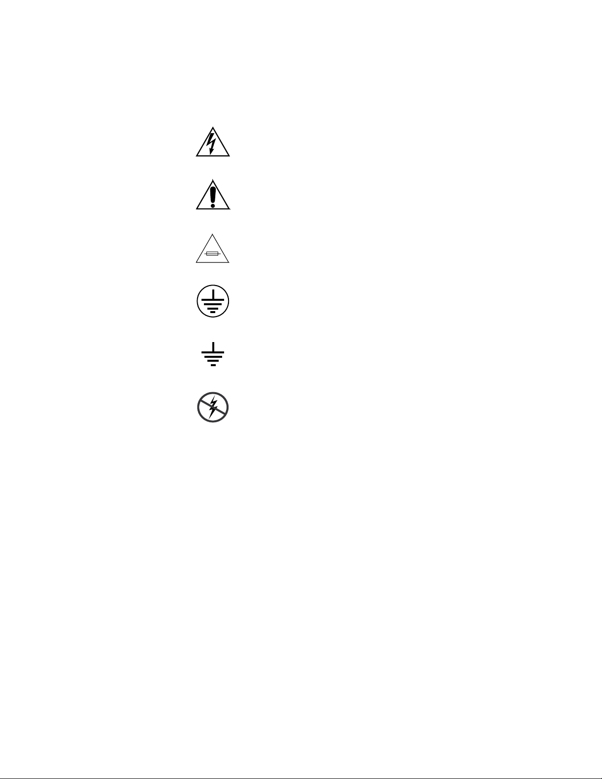
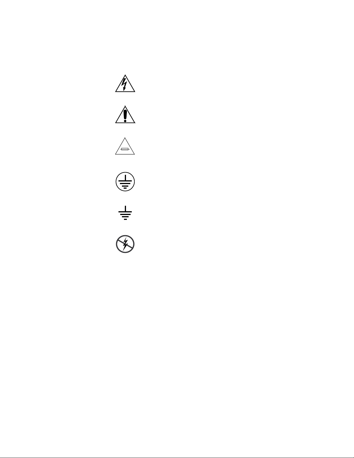
Symbols on the Product
The following symbols may appear on the product:
Warnings
Indicates that dangerous high voltage is present within the
equipment enclosure that may be of sufficient magnitude to
constitute a risk of electric shock.
Indicates that user, operator or service technician should refer
to product manual(s) for important operating, maintenance,
or service instructions.
This is a prompt to note fuse rating when replacing fuse(s).
The fuse referenced in the text must be replaced with one
having the ratings indicated.
Identifies a protective grounding terminal which must be connected to earth ground prior to making any other equipment
onnections.
c
Warnings
Identifies an external protective grounding terminal which
may be connected to earth ground as a supplement to an
internal grounding terminal.
Indicates that static sensitive components are present which
may be damaged by electrostatic discharge. Use anti-static
procedures, equipment and surfaces during servicing.
The following warning statements identify conditions or practices that can
result in personal injury or loss of life:
Dangerous voltage or current may be present — Disconnect power and remove
battery (if applicable) before removing protective panels, soldering, or
replacing components.
Do not service alone — Do not internally service this product unless another
person capable of rendering first aid and resuscitation is present.
Remove jewelry — Prior to servicing, remove jewelry such as rings, watches,
and other metallic objects.
Avoid exposed circuitry — Do not touch exposed connections, components or
circuitry when power is present.
Sonata Series — Planning and Installation Manual 10
Page 11

Cautions
Use proper power cord — Use only the power cord supplied or specified for
this product.
Ground product — Connect the grounding conductor of the power cord to
earth ground.
Operate only with covers and enclosure panels in place — Do not operate this
product when covers or enclosure panels are removed.
Use correct fuse — Use only the fuse type and rating specified for this
product.
Use only in dry environment — Do not operate in wet or damp conditions.
Use only in non-explosive environment — Do not operate this product in an
explosive atmosphere.
High leakage current may be present — Earth connection of product is essential
before connecting power.
Dual power supplies may be present — Be certain to plug each power supply
cord into a separate branch circuit employing a separate service ground.
Disconnect both power supply cords prior to servicing.
Cautions
Double pole neutral fusing — Disconnect mains power prior to servicing.
Use proper lift points — Do not use door latches to lift or move equipment.
Avoid mechanical hazards — Allow all rotating devices to come to a stop before
servicing.
The following caution statements identify conditions or practices that can
result in damage to equipment or other property:
Use correct power source — Do not operate this product from a power source
that applies more than the voltage specified for the product.
Use correct voltage setting — If this product lacks auto-ranging power sup-
plies, before applying power ensure that the each power supply is set to
match the power source.
Provide proper ventilation — To prevent product overheating, provide equip-
ment ventilation in accordance with installation instructions.
Use anti-static procedures — Static sensitive components are present which
may be damaged by electrostatic discharge. Use anti-static procedures,
equipment and surfaces during servicing.
Do not operate with suspected equipment failure — If you suspect product damage
or equipment failure, have the equipment inspected by qualified service
personnel.
Sonata Series — Planning and Installation Manual 11
Page 12

Cautions
Ensure mains disconnect — If mains switch is not provided, the power cord(s)
of this equipment provide the means of disconnection. The socket outlet
must be installed near the equipment and must be easily accessible. Verify
that all mains power is disconnected before installing or removing power
supplies and/or options.
Route cable properly — Route power cords and other cables so that they ar not
likely to be damaged. Properly support heavy cable bundles to avoid con
nector damage.
Use correct power supply cords — Power cords for this equipment, if provided,
meet all North American electrical codes. Operation of this equipment at
voltages exceeding 130 VAC requires power supply cords which comply
with NEMA configurations. International power cords, if provided, have
the approval of the country of use.
Use correct replacement battery — This product may contain batteries. To
reduce the risk of explosion, check polarity and replace only with the same
or equivalent type recommended by manufacturer. Dispose of used bat
teries according to the manufacturer’s instructions.
Troubleshoot only to board level — Circuit boards in this product are densely
populated with surface mount technology (SMT) components and applica
tion specific integrated circuits (ASICS). As a result, circuit board repair at
the component level is very difficult in the field, if not impossible. For war
ranty compliance, do not troubleshoot systems beyond the board level.
-
-
-
-
Sonata Series — Planning and Installation Manual 12
Page 13

Sicherheit – Überblick
Lesen und befolgen Sie die wichtigen Sicherheitsinformationen dieses
Abschnitts. Beachten Sie insbesondere die Anweisungen bezüglich
Brand-, Stromschlag- und Verletzungsgefahren. Weitere spezifische, hier
nicht aufgeführte Warnungen finden Sie im gesamten Handbuch.
WARNUNG Alle Anweisungen in diesem Handbuch, die das Abnehmen der
Geräteabdeckung oder des Gerätegehäuses erfordern, dürfen nur von
qualifiziertem Servicepersonal ausgeführt werden. Um die
Stromschlaggefahr zu verringern, führen Sie keine Wartungsarbeiten
außer den in den Bedienungsanleitungen genannten Arbeiten aus, es sei
denn, Sie besitzen die entsprechende Qualifikationen für diese Arbeiten.
Sicherheit – Begriffe und Symbole
Cautions
In diesem Handbuch verwendete Begriffe
Sicherheitsrelevante Hinweise können in diesem Handbuch in der folgenden Form auftauchen:
WARNUNG Warnungen weisen auf Situationen oder Vorgehensweisen hin, die
Verletzungs- oder Lebensgefahr bergen.
VORSICHT Vorsichtshinweise weisen auf Situationen oder Vorgehensweisen hin, die zu
Schäden an Ausrüstungskomponenten oder anderen Gegenständen oder
zum zeitweisen Ausfall wichtiger Komponenten in der Arbeitsumgebung
führen können.
Hinweise am Produkt
Die folgenden Hinweise können sich am Produkt befinden:
GEFAHR — Wenn Sie diesen Begriff lesen, besteht ein unmittelbares Verlet-
zungsrisiko.
WARNUNG — Wenn Sie diesen Begriff lesen, besteht ein mittelbares Verlet-
zungsrisiko.
VORSICHT — Es besteht ein Risiko für Objekte in der Umgebung, den Mixer
selbst oder andere Ausrüstungskomponenten.
Sonata Series — Planning and Installation Manual 13
Page 14
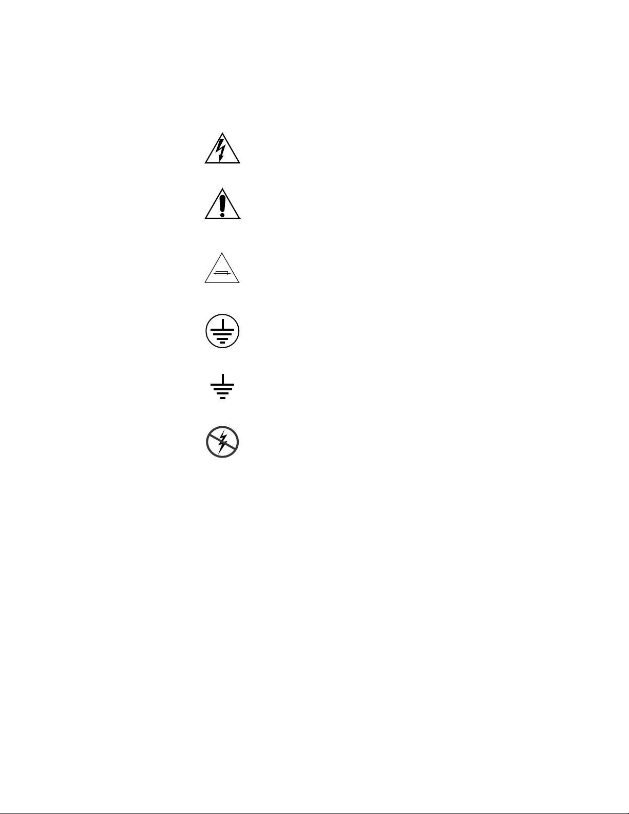
Symbole am Produkt
Die folgenden Symbole können sich am Produkt befinden:
Cautions
Weist auf eine gefährliche Hochspannung im Gerätegehäuse
hin, die stark genug sein kann, um eine Stromschlaggefahr
darzustellen.
Weist darauf hin, dass der Benutzer, Bediener oder Servicetechniker wichtige Bedienungs-,
weisungen in den Produkthandbüchern lesen sollte.
Dies ist eine Aufforderung, beim Wechsel von Sicherungen
auf deren Nennwert zu achten. Die im Text angegebene Sicherung muss durch eine Sicherung ersetzt werden, die die
angege
Weist auf eine Schutzerdungsklemme hin, die mit dem
Erdungskontakt verbunden werden muss, bevor weitere Ausrüstungskomponenten angeschlossen werden.
benen Nennwerte besitzt.
Wartungs- oder Servicean-
Warnungen
Weist auf eine externe Schutzerdungsklemme hin, die als
Ergänzung zu einem internen Erdungskontakt an die Erde
angeschlossen werden kann.
Weist darauf hin, dass es statisch empfindliche Komponenten
gibt, die durch eine elektrostatische Entladung beschädigt
werden können. Verwenden Sie antistatische Prozeduren,
Ausrüstung und Oberflächen während der Wartung.
Die folgenden Warnungen weisen auf Bedingungen oder Vorgehensweisen
hin, die Verletzungs- oder Lebensgefahr bergen:
Gefährliche Spannungen oder Ströme — Schalten Sie den Strom ab, und ent-
fernen Sie ggf. die Batterie, bevor sie Schutz
oder Komponenten austauschen.
Servicearbeiten nicht alleine ausführen — Führen Sie interne Servicearbeiten nur
aus, wenn eine weitere Person anwesend ist, die erste Hilfe leisten und
Wiederbelebungsmaßnahmen einleiten kann.
abdeckungen abnehmen, löten
Schmuck abnehmen — Legen Sie vor Servicearbeiten Schmuck wie Ringe,
Uhren und andere metallische Objekte ab.
Sonata Series — Planning and Installation Manual 14
Page 15

Cautions
Keine offen liegenden Leiter berühren — Berühren Sie bei eingeschalteter Strom-
zufuhr keine offen liegenden Leitungen, Komponenten oder Schaltungen.
Richtiges Netzkabel verwenden — Verwenden Sie nur das mitgelieferte Netzk-
abel oder ein Netzkabel, das den Spezifikationen für dieses Produkt
entspricht.
Gerät erden — Schließen Sie den Erdleiter des Netzkabels an den Erdung-
skontakt an.
Gerät nur mit angebrachten Abdeckungen und Gehäuseseiten betreiben — Schalten Sie
dieses Gerät nicht ein, wenn die Abdeckungen oder Gehäuseseiten entfernt
wurden.
Richtige Sicherung verwenden — Verwenden Sie nur Sicherungen, deren Typ
und Nennwert den Spezifikationen für dieses Produkt entsprechen.
Gerät nur in trockener Umgebung verwenden — Betreiben Sie das Gerät nicht in
nassen oder feuchten Umgebungen.
Gerät nur verwenden, wenn keine Explosionsgefahr besteht — Verwenden Sie dieses
Produkt nur in Umgebungen, in denen keinerlei Explosionsgefahr besteht.
Hohe Kriechströme — Das Gerät muss vor dem Einschalten unbedingt geerdet
werden.
Doppelte Spannungsversorgung kann vorhanden sein — Schließen Sie die beiden
Anschlußkabel an getrennte Stromkreise an. Vor Servicearbeiten sind beide
Anschlußkabel vom Netz zu trennen.
Zweipolige, neutrale Sicherung — Schalten Sie den Netzstrom ab, bevor Sie mit
den Servicearbeiten beginnen.
Fassen Sie das Gerät beim Transport richtig an — Halten Sie das Gerät beim Trans-
port nicht an Türen oder anderen beweglichen Teilen fest.
Gefahr durch mechanische Teile — Warten Sie, bis der Lüfter vollständig zum
Halt gekommen ist, bevor Sie mit den Servicearbeiten beginnen.
Vorsicht
Die folgenden Vorsichtshinweise weisen auf Bedingungen oder Vorgehensweisen hin, die zu Schäden an Ausrüstungskomponenten oder
anderen Gegenständen führen können:
Gerät nicht öffnen — Durch das unbefugte Öffnen wird die Garantie ungültig.
Richtige Spannungsquelle verwenden — Betreiben Sie das Gerät nicht an einer
Spannungsquelle, die eine höhere Spannung liefert als in den Spezifika
tionen für dieses Produkt angegeben.
Gerät ausreichend belüften — Um eine Überhitzung des Geräts zu vermeiden,
müssen die Ausrüstungskomponenten entsprechend den Installationsan
Sonata Series — Planning and Installation Manual 15
-
-
Page 16

Cautions
weisungen belüftet werden. Legen Sie kein Papier unter das Gerät. Es
könnte die Belüftung behindern. Platzieren Sie das Gerät auf einer ebenen
Oberfläche.
Antistatische Vorkehrungen treffen — Es gibt statisch empfindliche Kompo-
nenten, die durch eine elektrostatische Entladung beschädigt werden können. Verwenden Sie antistatische Prozeduren, Ausrüstung und
Oberflächen während der Wartung.
CF-Karte nicht mit einem PC verwenden — Die CF-Karte ist speziell formatiert.
Die auf der CF-Karte gespeicherte Software könnte gelöscht werden.
Gerät nicht bei eventuellem Ausrüstungsfehler betreiben — Wenn Sie einen Produk-
tschaden oder Ausrüstungsfehler vermuten, lassen Sie die Komponente
von einem qualifizierten Servicetechniker untersuchen.
Kabel richtig verlegen — Verlegen Sie Netzkabel und andere Kabel so, dass Sie
nicht beschädigt werden. Stützen Sie schwere Kabelbündel ordnungs
gemäß ab, damit die Anschlüsse nicht beschädigt werden.
Richtige Netzkabel verwenden — Wenn Netzkabel mitgeliefert wurden, erfüllen
diese alle nationalen elektrischen Normen. Der Betrieb dieses Geräts mit
Spannungen über 130 V AC erfordert Netzkabel, die NEMA-Konfigura
tionen entsprechen. Wenn internationale Netzkabel mitgeliefert wurden,
sind diese für das Verwendungsland zugelassen.
-
-
Richtige Ersatzbatterie verwenden — Dieses Gerät enthält eine Batterie. Um die
Explosionsgefahr zu verringern, prüfen Sie die Polarität und tauschen die
Batterie nur gegen eine Batterie desselben Typs oder eines gleichwertigen,
vom Hersteller empfohlenen Typs aus. Entsorgen Sie gebrauchte Batterien
entsprechend den Anweisungen des Batterieherstellers.
Das Gerät enthält keine Teile, die vom Benutzer gewartet werden können.
Wenden Sie sich bei Problemen bitte an den nächsten Händler.
Sonata Series — Planning and Installation Manual 16
Page 17

Consignes de sécurité
Il est recommandé de lire, de bien comprendre et surtout de respecter les
informations relatives à la sécurité qui sont exposées ci-après, notamment
les consignes destinées à prévenir les risques d’incendie, les décharges élec
triques et les blessures aux personnes. Les avertissements complémentaires, qui ne sont pas nécessairement repris ci-dessous, mais présents dans
toutes les sections du manuel, sont également à prendre en considération.
AVERTISSEMENT Toutes les instructions présentes dans ce manuel qui concernent
l’ouverture des capots ou des logements de cet équipement sont
destinées exclusivement à des membres qualifiés du personnel de
maintenance. Afin de diminuer les risques de décharges
électriques, ne procédez à aucune intervention d’entretien autre
que celles contenues dans le manuel de l’utilisateur, à moins que
vous ne soyez habilité pour le faire.
Cautions
-
Consignes et symboles de sécurité
Termes utilisés dans ce manuel
Les consignes de sécurité présentées dans ce manuel peuvent apparaître
sous les formes suivantes:
AVERTISSEMENT Les avertissements signalent des conditions ou des pratiques
susceptibles d’occasionner des blessures graves, voire même
fatales.
ATTENTION Les mises en garde signalent des conditions ou des pratiques
susceptibles d’occasionner un endommagement à l’équipement ou
aux installations, ou de rendre l’équipement temporairement non
opérationnel, ce qui peut porter préjudice à vos activités.
Signalétique apposée sur le produit
La signalétique suivante peut être apposée sur le produit:
DANGER — risque de danger imminent pour l’utilisateur.
AVERTISSEMENT — Risque de danger non imminent pour l’utilisateur.
MISE EN GARDE — Risque d’endommagement du produit, des installations
ou des autres équipements.
Sonata Series — Planning and Installation Manual 17
Page 18
Symboles apposés sur le produit
Les symboles suivants peut être apposés sur le produit:
Signale la présence d’une tension élevée et dangereuse dans le
boîtier de l’équipement ; cette tension peut être suffisante
pour cons
Signale que l’utilisateur, l’opérateur ou le technicien de maintenance doit faire référence au(x)
naissance des instructions d’utilisation, de maintenance ou
d’entr
Il s’agit d’une invite à prendre note du calibre du fusible lors
du remplacement de ce dernier. Le fusible auquel il est fait
référence dans le texte doit être remplacé par un fusible du
même calibre.
Identifie une borne de protection de mise à la masse qui doit
être raccordée correctement avant de procéder au raccordement des autres équipements.
tituer un risque de décharge électrique.
etien.
Cautions
manuel(s) pour prendre con-
Avertissements
Identifie une borne de protection de mise à la masse qui peut
être connectée en tant que borne de mise à la masse supplémentaire.
Signale la présence de composants sensibles à l’électricité statique et qui sont susceptibles d’être endommagés par une
déchar
ments et des surfaces antistatiques dur
d’entretien.
Les avertissements suivants signalent des conditions ou des pratiques susceptibles d’occasionner des blessures graves, voire même fatales:
Présence possible de tensions ou de courants dangereux — Mettez hors tension,
débranchez et retirez la pile (le cas échéant) avant de déposer les couvercles
de protection, de défaire une soudure ou de remplacer des composants.
Ne procédez pas seul à une intervention d’entretien — Ne réalisez pas une interven-
tion d’entretien interne sur ce produit
pour fournir les premiers soins en cas d’accident.
ge électrostatique. Utilisez des procédures, des équipe-
ant les interventions
si une personne n’est pas présente
Sonata Series — Planning and Installation Manual 18
Page 19

Cautions
Retirez tous vos bijoux — Avant de procéder à une intervention d’entretien,
retirez tous vos bijoux, notamment les bagues, la montre ou tout autre objet
métallique.
Évitez tout contact avec les circuits exposés — Évitez tout contact avec les connex-
ions, les composants ou les circuits exposés s’ils sont sous tension.
Utilisez le cordon d’alimentation approprié — Utilisez exclusivement le cordon
d’alimentation fourni avec ce produit ou spécifié pour ce produit.
Raccordez le produit à la masse — Raccordez le conducteur de masse du cordon
d’alimentation à la borne de masse de la prise secteur.
Utilisez le produit lorsque les couvercles et les capots sont en place — N’utilisez pas
ce produit si les couvercles et les capots sont déposés.
Utilisez le bon fusible — Utilisez exclusivement un fusible du type et du
calibre spécifiés pour ce produit.
Utilisez ce produit exclusivement dans un environnement sec — N’utilisez pas ce
produit dans un environnement humide.
Utilisez ce produit exclusivement dans un environnement non explosible — N’utilisez
pas ce produit dans un environnement dont l’atmosphère est explosible.
Mises en garde
Présence possible de courants de fuite — Un raccordement à la masse est indis-
pensable avant la mise sous tension.
Deux alimentations peuvent être présentes dans l’équipement — Assurez vous que
chaque cordon d’alimentation est raccordé à des circuits de terre séparés.
Débranchez les deux cordons d’alimentation avant toute intervention.
Fusion neutre bipolaire — Débranchez l’alimentation principale avant de pro-
céder à une intervention d’entretien.
Utilisez les points de levage appropriés — Ne pas utiliser les verrous de la porte
pour lever ou déplacer l’équipement.
Évitez les dangers mécaniques — Laissez le ventilateur s’arrêter avant de pro-
céder à une intervention d’entretien.
Les mises en garde suivantes signalent les conditions et les pratiques susceptibles d’occasionner des endommagements à l’équipement et aux installations:
N’ouvrez pas l’appareil — Toute ouverture prohibée de l’appareil aura pour
effet d’annuler la garantie.
Utilisez la source d’alimentation adéquate — Ne branchez pas ce produit à une
source d’alimentation qui utilise une tension supérieure à la tension nomi
nale spécifiée pour ce produit.
Sonata Series — Planning and Installation Manual 19
-
Page 20

Cautions
Assurez une ventilation adéquate — Pour éviter toute surchauffe du produit,
assurez une ventilation de l’équipement conformément aux instructions
d’installation. Ne déposez aucun document sous l’appareil — ils peuvent
gêner la ventilation. Placez l’appareil sur une surface plane.
Utilisez des procédures antistatiques - Les composants sensibles à l’électricité
statique présents dans l’équipement sont susceptibles d’être endommagés
par une décharge électrostatique. Utilisez des procédures, des équipements
et des surfaces antistatiques durant les interventions d’entretien.
N’utilisez pas la carte CF avec un PC — La carte CF a été spécialement formatée.
Le logiciel enregistré sur la carte CF risque d’être effacé.
N’utilisez pas l’équipement si un dysfonctionnement est suspecté — Si vous sus-
pectez un dysfonctionnement du produit, faites inspecter celui-ci par un
membre qualifié du personnel d’entretien.
Acheminez les câbles correctement — Acheminez les câbles d’alimentation et les
autres câbles de manière à ce qu’ils ne risquent pas d’être endommagés.
Supportez correctement les enroulements de câbles afin de ne pas endom
mager les connecteurs.
-
Utilisez les cordons d’alimentation adéquats — Les cordons d’alimentation de cet
équipement, s’ils sont fournis, satisfont aux exigences de toutes les régle
mentations régionales. L’utilisation de cet équipement à des tensions
dépassant les 130
aux exigences des configurations NEMA. Les cordons internationaux, s’ils
sont fournis, ont reçu l’approbation du pays dans lequel l’équipement est
utilisé.
Utilisez une pile de remplacement adéquate — Ce produit renferme une pile. Pour
réduire le risque d’explosion, vérifiez la polarité et ne remplacez la pile que
par une pile du même type, recommandée par le fabricant. Mettez les piles
usagées au rebut conformément aux instructions du fabricant des piles.
Cette unité ne contient aucune partie qui peut faire l’objet d’un entretien
par l’utilisateur. Si un problème survient, veuillez contacter votre distribu
teur local.
V en c.a. requiert des cordons d’alimentation qui satisfont
-
-
Sonata Series — Planning and Installation Manual 20
Page 21

Regulatory Notices
Certifications and Compliances
FCC Emission Control
This equipment has been tested and found to comply with the limits for a
Class A digital device, pursuant to Part 15 of the FCC Rules. These limits
are designed to provide reasonable protection against harmful interference
when the equipment is operated in a commercial environment. This equip
ment generates, uses, and can radiate radio frequency energy and, if not
installed and used in accordance with the instruction manual, may cause
harmful interference to radio communications. Operation of this equip
ment in a residential area is likely to cause harmful interference in which
case the user will be required to correct the interference at his own expense.
Changes or modifications not expressly approved by Grass Valley can
affect emission compliance and could void the user’s authority to operate
this equipment.
-
-
Canadian EMC Notice of Compliance
This digital apparatus does not exceed the Class A limits for radio noise
emissions from digital apparatus set out in the Radio Interference Regula
tions of the Canadian Department of Communications.
Le présent appareil numérique n’emet pas de bruits radioélectriques
dépassant les limites applicables aux appareils numeriques de la classe A
préscrites dans le Règlement sur le brouillage radioélectrique édicte par le
ministère des Communications du Canada.
EN55022 Class A Warning
In a domestic environment, products that comply with Class A may cause
radio interference in which case the user may be required to take adequate
measures.
-
Sonata Series — Planning and Installation Manual 21
Page 22

Canadian Certified Power Cords
Canadian approval includes the products and power cords appropriate for
use in the North America power network. All other power cords supplied
are approved for the country of use.
Canadian Certified AC Adapter
Canadian approval includes the AC adapters appropriate for use in the
North America power network. All other AC adapters supplied are
approved for the country of use.
Laser Compliance
Laser Safety Requirements
The device used in this product is a Class 1 certified laser product. Operating this product outside specifications or altering from its original design
may result in hazardous radiation exposure, and may be considered an act
of modifying or new manufacturing of a laser product under U.S. regula
tions contained in 21CFR Chapter 1, subchapter J or CENELEC regulations
in HD 482 S1. People performing such an act are required by law to recertify
and reidentify this product in accordance with provisions of 21CFR sub
chapter J for distribution within the U.S.A., and in accordance with
CENELEC HD 482 S1 for distribution within countries using the IEC 825
standard.
Certifications and Compliances
-
-
Laser Safety
Laser safety in the United States is regulated by the Center for Devices and
Radiological Health (CDRH). The laser safety regulations are published in
the “Laser Product Performance Standard,” Code of Federal Regulation
(CFR), Title 21, Subchapter J.
The International Electrotechnical Commission (IEC) Standard 825, “Radiation of Laser Products, Equipment Classification, Requirements and
User’s Guide,” governs laser products outside the United States. Europe
and member nations of the European Free Trade Association fall under the
jurisdiction of the Comite European de Normalization Electrotechnique
(CENELEC).
For the CDRH: The radiant power is detected through a 7 mm aperture at
a distance of 200 mm from the source focused through a lens with a focal
length of 100 mm.
Sonata Series — Planning and Installation Manual 22
Page 23

For IEC compliance: The radiant power is detected through a 7 mm aperture at a distance of 100 mm from the source focused through a lens with a
focal length of 100 mm.
FCC Emission Limits
This device complies with Part 15 of the FCC Rules. Operation is subject to
the following two conditions: (1) This device may not cause harmful inter
ference, and (2) this device must accept any interference received,
including interference that may cause undesirable operation. This device
has been tested and found to comply with FCC Part 15 Class B limits for a
digital device when tested with a representative laser-based fiber optical
system that complies with ANSI X3T11 Fiber Channel Standard.
Certifications and Compliances
-
Sonata Series — Planning and Installation Manual 23
Page 24

Certifications:
Category Standard Designed/tested for compliance with:
ANSI / UL60950 “Standard for Safety of Information Technology Equipment - Safety - Part 1: General
IEC 60950 “Standard for Safety for Information Technology Equipment - Safety - Part 1: General
Safety
EMI
CAN/CSA C22.2, No. 60950 “Standard for Safety of Information Technology Equipment - Safety - Part 1: General
EN60950 Safety of Information Technology Equipment, including Electrical Business Equipment.
2006/95/EC Low Voltage Directive
EMC Directive 89/336/EEC via
EN 55103-1 and 2
EN 55103-1 standards Electromagnetic compatibility.
EN55103-2 standards Electromagnetic compatibility--Product family standard for audio, video, audio-visual
US FCC Class A
Canada FCC Industry Canada
Australia & New Zealand: AS/NZS 3548
Certifications and Compliances
Requirements”, (ANSI/UL 60950-1, First Edition, Dated April 1, 2003, with revision
through and including November 26, 2003.)
Requirements”, (IEC 60950-1, First Edition, 2001, Corrigendum 1:10-2002)
Requirements”, (CAN/CSA-C22.2 No. 60950-1-03. First Edition Dated April 1, 2003,
with revisions through and including November 26, 2003)
Audio, Video and Entertainment Lighting Control for the European Community.
Product family standard for audio, video, audio-visual and entertainment lighting control
apparatus for professional use.
Part 1 Emissions, Environment E1/E2
EN 55022: Class A Radiated and Conducted Emissions
EN 61000-3-2: Power Line Harmonic Emissions, Radiated Magnetic Field Emissions,
Peak Inrush Current
and entertainment lighting control apparatus for professional use.
Part 2 Immunity, Environment E1/E2
EN 50082-1: Immunity
EN 61000-4-2:
Electrostatic Discharge “ESD” Immunity
EN 61000-4-3:
Radiated RF Electromagnetic Field Immunity
EN 61000-4-4:
Electrical Fast Transient/Burst “EFT” Immunity
EN 61000-4-5: Surge Immunity
EN 61000-4-6: Conducted RF Immunity
EN 61000-4-11: Voltage Dips, Short Interruptions and Voltage Variations
Annex A - Radiated Magnetic Field Immunity
Note: This only applies to assemblies sensitive to magnetic fields
CISPR Pub. 22 (1985)
Sonata Series — Planning and Installation Manual 24
Page 25

Introduction
The Sonata Family
The Sonata family of products is designed to support the Multichannel
Audio Digital Interface (MADI) standard for digital audio signals. This
standard, also called AES10, is designed to provide an easy way to connect
many audio channels using a single audio cable. Sonata supports the orig
inal MADI standard, which provided 56 channels of digital audio at a 48
kHz sample rate as well as extensions to the standard to provide for 64
channels, and sample rates up to 96 kHz (with reduced channel count).
The Sonata products can be used to provide Input/Output for the Apex
Routing switcher and the Maestro Master Control switcher. Sonata can also
be used with any third party product that is MADI (AES10) compatible.
Section 1
-
In addition, the Sonata family of products is designed to support the needs
of on-air broadcasters with redundant power supplies and the ability to
lock to video references, a significant feature that is rarely seen in MADI
equipment from other manufacturers.
The Sonata MADI converters include the following:
Digital
M75
• Unbalanced AES to the MADI converter (SON-AU2MADI).
• MADI to Unbalanced AES converter (SON-MADI2AU).
M110
• Balanced AES the MADI converter (SON-MADI2AB).
• MADI to Balanced AES converter (SON-AB2MADI).
Analog
• MADI-to-analog converter (SON-MADI2AA).
• Analog-to-MADI converter (SON-AA2MADI).
Sonata Series — Planning and Installation Manual 25
Page 26

The SON-AU2MADI (75M) provides unbalanced 75 ohm BNC digital
audio connectivity. The SON-AB2MADI (110M) provides balanced 110
ohm twisted pair digital audio connectivity.
The SON-MADI2AU (M75) provides unbalanced 75 ohm BNC digital
audio connectivity; the SON-MADI2AB (M110) provides balanced 110 ohm
twisted pair digital audio connectivity. The SON-MADI2AA (MA) and
SON-AA2MADI (AM) provide balanced analog audio connectivity.
Sonata MADI Converters Features
Each MADI converter has the following features:
• Compact 1 RU boxes that convert analog audio to and from the MADI
Standard.
• One of the most dense (channels per rack unit) analog conversion
choices available at any price.
Sonata MADI Converters Features
• Full 64 analog channels of conversion supporting the entire 64-channel
MADI mode arranged as 32 stereo pairs.
• One of the only analog conversion choices available that can synchronize to video references, including Tri-level.
• Designed to have excellent analog audio performance.
• Full 24-bit conversion with a 112 dB dynamic range.
• Full Sonata family reference section for maximum flexibility and compatibility with Apex and Maestro product lines.
• Supports 48 kHz sample rate locked to 6 different video reference frequencies & 44.1 kHz, 48 kHz, 88.2 kHz, and 96 kHz locked to AES sync
or Word-Clock reference.
• Supports eight different audio reference levels, from +24 dBu = 0 dBFS
to +10 dBu = 0 dBFS in 2 dB steps.
• Analog inputs and output are static and RF protected.
• Analog inputs and outputs use new technology to provide superior
common mode rejection insuring maximum sound quality.
• Full balance audio I/O using the industry standard Tascam pinout.
Sonata Series — Planning and Installation Manual 26
Page 27

Sonata MADI Converters Features
• Automatically locks to standard Video or Tri-Level Sync (TLS) reference
with loop-through inputs for the following standards:
• 480i/59.94
• 575i/50
• 1080i/59.94
• 1080i/50
• 720p/59.94
• 720p/50
• Supports AES reference (sometimes called DARS) with loop-
through inputs.
• Supports 48 kHz sample rate locked to 6 different video reference
frequencies & 44.1 kHz, 48 kHz, 88.2 kHz, and 96 kHz locked to AES
sync or Word-Clock reference.
• Supports Word-Clock reference.
• Can also lock to the first AES input for backup purposes.
• Maestro Accessory providing expansion to 16 channel I/O.
• Can be plugged directly into the Maestro Master Control Switcher
for Background sources A, B, C, & D.
• Can also be used to expand to 16 channels of Mix Over sources A,
B, C, & D.
• Output expansion of Maestro providing Program, Preset, and Clean
feed outputs.
• Apex accessory also provides for input sample rate conversion and/or
Analog-to-Digital and Digital-to-Analog Conversion.
• Apex Accessory providing 32 AES pairs on a single coaxial cable to
reduce system wiring. The Apex router has both MADI inputs and outputs.
Sonata Series — Planning and Installation Manual 27
Page 28

Sonata AES-to-MADI Converters
The AES-to-MADI converters (both the 75M and 110M) have the following
features:
• Compact 1 RU box that converts 32 AES pairs to a single MADI output.
• Supports both 56 and 64 channel modes.
• Supports 75 ohm or 110 ohm versions of AES/EBU signals as specific
in AES3-2003 and AES3id-2001.
• Supports 48 kHz sample rate locked to 6 different video reference frequencies & 44.1 kHz, 48 kHz, and 96 kHz locked to AES sync or WordClock Reference.
• Full Sonata family reference section for maximum flexibility.
• Provides full-time sample-rate conversion for all inputs. All AES inputs
are sample-rate converted to the reference sample rate of 48 kHz. Can
be used to synchronize otherwise asynchronous audio sources.
• Full Dolby E support (will pass both Dolby E and Dolby Digital signals
automatically bypassing the sample-rate converters).
Sonata AES-to-MADI Converters
• Passes the entire AES signal complete with Status Block information for
complete data stream transparency.
• Provides dual MADI outputs for Redundant links.
• Fully Redundant power supplies and power connectors for on-air reliability.
•Power alarms.
• Maestro Accessory providing 16 channel input expansion.
• Can be plugged directly into the Maestro Master Control Switcher
for Background sources A, B, C, & D.
• Can also be used to expand to 16 channels of Mix Over sources A,
B, C, & D.
• Apex Accessory provides input sample rate conversion from 32 to 96
kHz to the Apex router.
• Apex Accessory providing 32 AES pairs on a single coaxial cable to
reduce system wiring.
Sonata Series — Planning and Installation Manual 28
Page 29

Sonata MADI-to-AES Converters
The MADI-to-AES converters (both the M75 and M110) have the following
features:
• Compact 1 RU box that converts 1 MADI stream to 32 AES output pairs
MADI output.
• Two MADI inputs are provided. The second input will take over if the
first one stops working.
• Supports both 56 and 64 channel modes.
• Supports 75 ohm or 110 ohm versions of AES/EBU signals as specified
in AES3-2003 and AES-3id-2001.
• Full Dolby E support.
• Passes the entire AES signal complete with Status Block information for
complete data stream transparency.
• Full Sonata family reference section for maximum flexibility.
• Supports 48 kHz sample rate locked to 6 different video reference frequencies & 44.1 kHz, 48 kHz, 88.2 kHz, and 96 kHz locked to AES sync,
MADI input, or Word-Clock reference.
Sonata MADI-to-AES Converters
• Fully Redundant power supplies and power connectors for on-air reliability.
•Power alarms.
• Maestro Accessory providing 16 channel expansion with outputs for
Program, Preset, Clean Feed, and Metering.
• Apex Accessory providing 32 AES pairs on a single coaxial cable to
reduce system wiring.
Sonata Series — Planning and Installation Manual 29
Page 30

Sonata Analog-to-MADI (AM) and MADI-to-Analog (MA) Converters
Sonata Analog-to-MADI (AM) and MADI-to-Analog (MA)
Converters
The Analog-to-MADI (AM) and MADI-to-Analog (MA) converters have
the following features:
• Compact 1 RU boxes that convert analog audio to and from MADI
• One of the most dense (channels per rack unit) analog conversion
choices available at any price
• Full 64 analog channels of conversion supporting the entire 64-channel
MADI mode arranged as 32 stereo pairs
• One of the only analog conversion choices available that can synchronize to video references including Tri-level
• Designed to have excellent analog audio performance and sound 'right'
• Full 24-bit conversion with a 112 dB dynamic range
• Full Sonata family reference section for maximum flexibility and compatibility with Apex and Maestro product lines
• Supports 48 kHz sample rate locked to 6 different video reference frequencies & 44.1 kHz, 48 kHz, 88.2 kHz, and 96 kHz locked to AES sync,
MADI input, or Word-Clock reference. The MADI-to-Analog converter
can also lock to the MADI input.
• Supports eight different audio reference levels, from +24 dBu = 0 dBFS
to +10 dBu = 0 dBFS in 2 dB steps.
• Analog inputs and output are static and RF protected
• Analog inputs and outputs use new technology to provide superior
common mode rejection insuring maximum sound quality
• Full balance audio I/O using the industry standard Tascam pinout
Sonata Series — Planning and Installation Manual 30
Page 31

Planning Guide
This planning guide serves as a very short tutorial on the MADI standard,
as well as to provide suggestions as to the various ways that the Sonata con
verter can be used.
Quick Check List
The following is a short checklist and a summary of the planning section:
1. The MADI Standard.
2. Sample-Rate Conversion.
3. Reference Considerations.
4. Dolby E and Dolby Digital signals.
Section 2
-
5. Stand-alone use.
6. Interfacing to Maestro
The MADI Standard
The MADI standard was originally developed to help recording studios
connect mixing consoles to multi-track tape machines. Since its inception,
it has been frequently used for audio-only applications. The Sonata product
provides the opportunity to put the MADI standard to good use in a videobased application because it can be locked to both SD and HD video refer
ence as well as being completely compatible with MADI devices usually
used in audio only applications.
The big advantage of using the MADI standard is that devices can provide
up to 64 channels of audio (usually arranged as 32 stereo pairs) on a single
coaxial cable. The data rate is 125 Mbit/sec, and the data stream is asyn
chronous and not locked to any reference. The AES10 standard requires
operation up to 50 meters of cable (approximately 164 feet). Normally,
equalization to extend cable length is not employed, but a fiber-optic
version of the MADI signal is specified in the AES10 standard. The Sonata
-
-
Sonata Series — Planning and Installation Manual 31
Page 32

Section 2 — Planning Guide
product, which provides a 75 ohm coax version of MADI, typically operates at distances up to 300 feet (100 meters), which is double the distance
specified in the AES10 standard.
The MADI standard requires that all 64 channels of audio are synchronous.
However, the MADI data stream isn't synchronized with a house reference;
for that reason, a reference is usually required for making and decoding
MADI streams.
There are several versions of the MADI standard in use, the most common
is the 56 channel version. There are also some MADI devices that pass 96
kHz digital audio but with half the channels supported because the 125
Mbit data-rate does not change.
Sample-Rate Conversion
Sample-rate converters, which are normally very expensive, are incorporated into the Sonata AES-to-MADI converters. These converters are provided as a cost effective way to synchronize otherwise asynchronous audio
sources such as CD players, which run at a 44.1 kHz sample rate. As well
as other playback devices that normally cannot be synchronized. These
sample-rate converters generate full 24-bit data. In addition, they can
accept signals that range of 32 kHz to 100 kHz sample rates.
The sample-rate converters are in-line for all inputs. There are provisions
for bypassing the sample rate converters. However, there are two situations
when they must be bypassed.
• The first is when a compressed audio signal such as Dolby E or Dolby
Digital is applied. The AES status block carries information as to
whether the data is normal audio or non-audio data. The Sonata AESto-MADI converter automatically senses the presence of this bit on an
input-by-input basis and bypasses the sample-rate converters for that
audio pair. It is acceptable to have many different audio sample rates
applied to the inputs of the Sonata converter as long as the output is
locked to a valid reference.
• The second situation is when bit-accurate MADI encoding is required.
This requirement is only possible with signals that are synchronous
with a reference. A rear panel DIP switch is provided in the Sonata converter that will force the bypass of the sample-rate converters when
desired. The user may also force the rate conversion to be active when
desired. The normal setting is automatic as described above. These settings are used for all 32 AES pairs.
32 Sonata Series — Planning and Installation Manual
Page 33

Reference Considerations
The Sonata AES-to-MADI converter must have a valid Reference signal
connected. This Reference signal is not optional. Which reference is used
will depend upon system issues and desired performance. Either the AES
(DARS) reference or the Word-Clock reference will provide the best audio
quality. A Digital Audio Reference Signal (DARS) signal is an AES3-for
matted audio signal that is capable of being referenced, locked, and distributed at a precise audio frame rate. Word Clock is a square wave at the
sampling frequency basic rate. This signal is not standardized, however it
may be looped, and is commonly carried on coaxial cable.
The AES11 synchronization standard requires that all AES signals in a
given system are locked together so that they are all on the same sample at
the same time. The best audio performance, especially when handling sur
round-sound signals, will occur when all channels are sample-accurate.
This accuracy can only be achieved when using AES (DARS) reference or
Word-Clock reference.
A video reference can also be used to provide a +/- 1 sample ambiguity
over a complete system for 59.94 Hz based video systems. For many 50 Hz
systems, there is no ambiguity. The audio will be locked correctly with
video reference when using video references in any digital audio system.
However, the sample delays can vary.
Reference Considerations
-
-
The supported sample-rates are as follows:
1. Video reference - 48 kHz only.
2. AES (DARS) reference - 44.1 kHz, 48 kHz, 88.2 kHz and 96 kHz.
3. Word-Clock reference - 44.1 kHz, 48 kHz, 88.2 kHz and 96 kHz.
The Sonata family Reference section automatically selects the preferred reference based upon the following priority:
1. Video reference
2. Audio reference (DARS)
3. Word Clock reference
4. First AES input reference
Note Using the first AES input reference is not recommended as a full-time refer-
ence because, if it were to fail or be switched upstream, the Sonata converter
could lose lock. This failure would affect all of the audio channels in the MADI
stream. The First AES input is should be used as a backup reference that
would be selected to if the primary reference failed.
5. MADI-to-AES and MADI-to-Analog are capable of locking to the
MADI input instead of the first AES input.
Sonata Series — Planning and Installation Manual 33
Page 34

Section 2 — Planning Guide
It is possible to feed more than one reference to the Sonata AES-to-MADI
converter, but the unit will select and use the reference highest in priority
order as shown above.
Dolby E and Dolby Digital signals
The Sonata AES-to-MADI converters are designed to correctly pass Dolby
E and Dolby Digital signals. In order to do this, the signals MUST be syn
chronous with the reference that is being used. The easiest way to guarantee synchronization is to use the same reference signal for both the
Sonata converter and any associated Dolby E devices. Dolby E devices
usually use standard Video Black for a reference. However, two different
references can be used simultaneously, such as Video Black for Dolby E and
AES (DARS) reference for the Sonata box only if they are both locked to a
common source. The Sonata converter passes the entire AES status block
intact, which is required for correct Dolby E operation. Many MADI
devices do not pass AES status block intact.
-
Note In order to pass non-audio signals, the signals MUST BE synchronous with
the reference that is applied to the Sonata converter.
Stand-Alone Use
The Sonata converter can be used as a stand-alone application as long as it
is locked to a reference.
Interfacing to Maestro
As shown in Figure 1, the Sonata AES-to-MADI converters can be used
with the Maestro Master Control switcher for two primary purposes:
• Expansion of the basic 8-channel I/O of the Maestro frame to 16-channels
• Addition of Background C and D inputs, and addition of Mix over C
and D inputs, not available on the standard Maestro’s rear panel. The
Background C inputs are required for full DVE functionality of the
Maestro product.
Note Maestro supports a maximum of two direct Audio Mixer sources, whether or
not the Audio Mixer MADI expansion is enabled. To connect directly to
Maestro without Sonata, use the BNCs labeled
34 Sonata Series — Planning and Installation Manual
Over A and Over B.
Page 35

Interfacing to Maestro
The Maestro Master Control switcher will map the various channels of its
MADI inputs in a very specific order which is hard wired. When using the
Sonata AES-to-MADI converter with the Maestro product the inputs must
be connected according to the tables in the
section. The unused channels are simply skipped and left empty when less
than the full 16 channels are used on a given Maestro input.
Both the front and rear Sonata panels are grouped into 8-pair sections that
are labeled A, B, C, and D to help in wiring and monitoring the operation
of the Sonata AES-to-MADI converter. These sections correspond to the
Background and Mix Over inputs of the Maestro Master Control switcher.
Sonata to Maestro Mapping Tables
Sonata Series — Planning and Installation Manual 35
Page 36

Section 2 — Planning Guide
8609_00
Video reference
AES Reference
A, B, C, & D
background
audio sources
(1-16 channels each,
arranged as 8 AES pairs)
A, B, C, & D
audio over sources
(1-16 channels each,
arranged as 8 AES pairs)
3/4
7/8
5/6
7/8
5/6
3/4
1/2
7/8
5/6
3/4
1/2
7/8
5/6
3/4
1/2
7/8
5/6
3/4
1/2
3/4
7/8
5/6
1/2
7/8
5/6
3/4
1/2
7/8
5/6
3/4
1/2
7/8
5/6
3/4
1/21/2
BG A INMON OUTSMTR OUTS
ALARM
PGM OUTS CF1 OUTS BG B IN MON INOVER B INOVER A IN
Pgm & CF1 audio
outputs (1-8
channels each)
Audio outputs to other equipment
Audio inputs from other equipment
INPUTS OUTPUTS
Audio router
When not in use, AES REF
connectors must be terminated
AES reference can be used
as an alternate reference
Figure 1. Sonata-to-Maestro Application with Fully-expanded Audio Inputs
36 Sonata Series — Planning and Installation Manual
Page 37

Interfacing to Maestro
Two MADI inputs are provided on the rear panel of the Maestro chassis.
These inputs are labled MADI IN-1 and IN-2. MADI IN-1 is used for Back
ground signals A, B, C, and D, each input supports 16 audio channels as 8
AES pairs. MADI IN-2 is used for Audio Mix Over signals A, B, C, & D,
each also supporting 16 audio channels as 8 AES pairs.
It is not possible to share the Background and Mix Over inputs on a single
MADI converter box. It is possible to use a Sonata AES-to-MADI converter
for only the background signals while using the Maestro rear panel AES
connectors for Mix over signals (see
MADI converter or an Apex router with MADI connections is required for
full 16 channel support for either background or mix over signals.
Figure 2). However, a Sonata AES-to-
-
Sonata Series — Planning and Installation Manual 37
Page 38

Section 2 — Planning Guide
8609_01
Video reference
AES Reference
A, B, & C
background
audio sources
(1-16 channels each)
3/4
7/8
5/6
7/8
5/6
3/4
1/2
7/8
5/6
3/4
1/2
7/8
5/6
3/4
1/2
7/8
5/6
3/4
1/2
3/4
7/8
5/6
1/2
7/8
5/6
3/4
1/2
7/8
5/6
3/4
1/2
7/8
5/6
3/4
1/21/2
BG A INMON OUTSMTR OUTS
ALARM
PGM OUTS CF1 OUTS BG B IN MON INOVER B INOVER A IN
Pgm & CF1 audio
outputs (1-8
channels each)
Audio outputs to other equipment
Audio inputs from other equipment
INPUTS OUTPUTS
Audio router
When not in use, AES REF
connectors must be terminated
Over A & B audio sources
(1-8 channels each)
AES reference can be used
as an alternate reference
Figure 2. Sonata-to-Maestro Application Showing Minimum Audio Inputs Required for DVE
Operation
38 Sonata Series — Planning and Installation Manual
Page 39

Interfacing to Maestro
Sonata to Maestro Mapping Tables
The following tables must be used when connecting a Sonata AES-toMADI converter to a Maestro Master Control.
Table 1. Sonata-to-Maestro Background Input Mapping
Sonata Input Connector Signal Name Maestro Input
A1 Input 1 (L&R) Background A Ch. 1&2
A2 Input 2 (L&R) Background A Ch. 3&4
A3 Input 3 (L&R) Background A Ch. 5&6
A4 Input 4 (L&R) Background A Ch. 7&8
A5 Input 5 (L&R) Background A Ch. 9&10
A6 Input 6 (L&R) Background A Ch. 11&12
A7 Input 7 (L&R) Background A Ch. 13&14
A8 Input 8 (L&R) Background A Ch. 15&16
B9 Input 9 (L&R) Background B Ch. 1&2
B10 Input 10 (L&R) Background B Ch. 3&4
B11 Input 11 (L&R) Background B Ch. 5&6
B12 Input 12 (L&R) Background B Ch. 7&8
B13 Input 13 (L&R) Background B Ch. 9&10
B14 Input 14 (L&R) Background B Ch. 11&12
B15 Input 15 (L&R) Background B Ch. 13&14
B16 Input 16 (L&R) Background B Ch. 15&16
C17 Input 17 (L&R) Background C Ch. 1&2
C18 Input 18 (L&R) Background C Ch. 3&4
C19 Input 19 (L&R) Background C Ch. 5&6
C20 Input 20 (L&R) Background C Ch. 7&8
C21 Input 21 (L&R) Background C Ch. 9&10
C22 Input 22 (L&R) Background C Ch. 11&12
C23 Input 23 (L&R) Background C Ch. 13&14
C24 Input 24 (L&R) Background C Ch. 15&16
D25 Input 25 (L&R) Background D Ch. 1&2
D26 Input 26 (L&R) Background D Ch. 3&4
D27 Input 27 (L&R) Background D Ch. 5&6
D28 Input 28 (L&R) Background D Ch. 7&8
D29 Input 29 (L&R) Background D Ch. 9&10
D30 Input 30 (L&R) Background D Ch. 11&12
D31 Input 31 (L&R) Background D Ch. 13&14
D32 Input 32 (L&R) Background D Ch. 15&16
Sonata Series — Planning and Installation Manual 39
Page 40

Section 2 — Planning Guide
Table 2. Sonata-to-Maestro Mix Over Input Mapping
Sonata Input Connector Signal Name Maestro Input
A1 Input 1 (L&R) Mix Over A Ch. 1&2
A2 Input 2 (L&R) Mix Over A Ch. 3&4
A3 Input 3 (L&R) Mix Over A Ch. 5&6
A4 Input 4 (L&R) Mix Over A Ch. 7&8
A5 Input 5 (L&R) Mix Over A Ch. 9&10
A6 Input 6 (L&R) Mix Over A Ch. 11&12
A7 Input 7 (L&R) Mix Over A Ch. 13&14
A8 Input 8 (L&R) Mix Over A Ch. 15&16
B9 Input 9 (L&R) Mix Over B Ch. 1&2
B10 Input 10 (L&R) Mix Over B Ch. 3&4
B11 Input 11 (L&R) Mix Over B Ch. 5&6
B12 Input 12 (L&R) Mix Over B Ch. 7&8
B13 Input 13 (L&R) Mix Over B Ch. 9&10
B14 Input 14 (L&R) Mix Over B Ch. 11&12
B15 Input 15 (L&R) Mix Over B Ch. 13&14
B16 Input 16 (L&R) Mix Over B Ch. 15&16
C17 Input 17 (L&R) Mix Over C Ch. 1&2
C18 Input 18 (L&R) Mix Over C Ch. 3&4
C19 Input 19 (L&R) Mix Over C Ch. 5&6
C20 Input 20 (L&R) Mix Over C Ch. 7&8
C21 Input 21 (L&R) Mix Over C Ch. 9&10
C22 Input 22 (L&R) Mix Over C Ch. 11&12
C23 Input 23 (L&R) Mix Over C Ch. 13&14
C24 Input 24 (L&R) Mix Over C Ch. 15&16
D25 Input 25 (L&R) Mix Over D Ch. 1&2
D26 Input 26 (L&R) Mix Over D Ch. 3&4
D27 Input 27 (L&R) Mix Over D Ch. 5&6
D28 Input 28 (L&R) Mix Over D Ch. 7&8
D29 Input 29 (L&R) Mix Over D Ch. 9&10
D30 Input 30 (L&R) Mix Over D Ch. 11&12
D31 Input 31 (L&R) Mix Over D Ch. 13&14
D32 Input 32 (L&R) Mix Over D Ch. 15&16
40 Sonata Series — Planning and Installation Manual
Page 41

Interfacing to Maestro
Table 3. Maestro-Sonata Output Mapping
Sonata Input Connector Signal Name Maestro Output
1 Output 1 (L&R) Program Ch. 1&2
2 Output 2 (L&R) Program A Ch. 3&4
3 Output 3 (L&R) Program A Ch. 5&6
4 Output 4 (L&R) Program A Ch. 7&8
5 Output 5 (L&R) Program A Ch. 9&10
6 Output 6 (L&R) Program A Ch. 11&12
7 Output 7 (L&R) Program A Ch. 13&14
8 Output 8 (L&R) Program A Ch. 15&16
9 Output 9 (L&R) Preset Ch. 1&2
10 Output 10 (L&R) Preset Ch. 3&4
11 Output 11 (L&R) Preset Ch. 5&6
12 Output 12 (L&R) Preset Ch. 7&8
13 Output 13 (L&R) Preset Ch. 9&10
14 Output 14 (L&R) Preset Ch. 11&12
15 Output 15 (L&R) Preset Ch. 13&14
16 Output 16 (L&R) Preset Ch. 15&16
17 Output 17 (L&R) Clean Feed Ch. 1&2
18 Output 18 (L&R) Clean Feed Ch. 3&4
19 Output 19 (L&R) Clean Feed Ch. 5&6
20 Output 20 (L&R) Clean Feed Ch. 7&8
21 Output 21 (L&R) Clean Feed Ch. 9&10
22 Output 22 (L&R) Clean Feed Ch. 11&12
23 Output 23 (L&R) Clean Feed Ch. 13&14
24 Output 24 (L&R) Clean Feed Ch. 15&16
25 Output 25 (L&R) Metering Ch. 1&2
26 Output 26 (L&R) Metering Ch. 3&4
27 Output 27 (L&R) Metering Ch. 5&6
28 Output 28 (L&R) Metering Ch. 7&8
29 Output 29 (L&R) Metering Ch. 9&10
30 Output 30 (L&R) Metering Ch. 11&12
31 Output 31 (L&R) Metering Ch. 13&14
32 Output 32 (L&R) Metering Ch. 15&16
Sonata Series — Planning and Installation Manual 41
Page 42

Section 2 — Planning Guide
Interfacing to Apex
MADI Input Mapping
The MADI inputs of the Apex router have a fixed channel assignment.
These channels can not be changed or remapped. However, the mode the
Apex router is running can change how the signals are addressed from the
control system.
The MADI inputs on the Apex router are hard wired into blocks or 32 AES
inputs, which correspond to the input cards. This means that a set of chan
nels sent to the Apex router must align with the 32 AES paths on a given
input card. You cannot span across multiple input cards while using MADI.
In addition, the Apex router MADI input replaces the normal AES inputs
on the corresponding input card. You cannot mix normal AES and MADI
inputs on a given input card. If you leave gaps or empty inputs to the
Sonata converter, then those inputs will be dead and will not usable in the
Apex router.
-
Sonata to Apex Mapping Tables
In standard stereo mode the Apex will address the channels as shown in
Ta bl e 4.
Table 4. Sonata-to-Apex Standard Stereo Mode Input Mapping
Sonata Input Connector Signal Name Apex Input Left Apex Input Right
A1 AES Pair 1 Left 1 Right 1
A2 AES Pair 2 Left 2 Right 2
A3 AES Pair 3 Left 3 Right 3
A4 AES Pair 4 Left 4 Right 4
A5 AES Pair 5 Left 5 Right 5
A6 AES Pair 6 Left 6 Right 6
A7 AES Pair 7 Left 7 Right 7
A8 AES Pair 8 Left 8 Right 8
B9 AES Pair 9 Left 9 Right 9
B10 AES Pair 10 Left 10 Right 10
B11 AES Pair 11 Left 11 Right 11
B12 AES Pair 12 Left 12 Right 12
B13 AES Pair 13 Left 13 Right 13
B14 AES Pair 14 Left 14 Right 14
B15 AES Pair 15 Left 15 Right 15
B16 AES Pair 16 Left 16 Right 16
C17 AES Pair 17 Left 17 Right 17
C18 AES Pair 18 Left 18 Right 18
C19 AES Pair 19 Left 19 Right 19
42 Sonata Series — Planning and Installation Manual
Page 43

Interfacing to Apex
C20 AES Pair 20 Left 20 Right 20
C21 AES Pair 21 Left 21 Right 21
C22 AES Pair 22 Left 22 Right 22
C23 AES Pair 23 Left 23 Right 23
C24 AES Pair 24 Left 24 Right 24
D25 AES Pair 25 Left 25 Right 25
D26 AES Pair 26 Left 26 Right 26
D27 AES Pair 27 Left 27 Right 27
D28 AES Pair 28 Left 28 Right 28
D29 AES Pair 29 Left 29 Right 29
D30 AES Pair 30 Left 30 Right 30
D31 AES Pair 31 Left 31 Right 31
D32 AES Pair 32 Left 32 Right 32
In Locked Stereo Mode the Apex will address the channels as shown in
Ta bl e 5.
Table 5. Sonata-to-Apex Locked Stereo Mode Input Mapping
Sonata Input Connector Signal Name Apex Input
A1 AES Pair 1 Input 1 (L&R)
A2 AES Pair 2 Input 2 (L&R)
A3 AES Pair 3 Input 3 (L&R)
A4 AES Pair 4 Input 4 (L&R)
A5 AES Pair 5 Input 5 (L&R)
A6 AES Pair 6 Input 6 (L&R)
A7 AES Pair 7 Input 7 (L&R)
A8 AES Pair 8 Input 8 (L&R)
B9 AES Pair 9 Input 9 (L&R)
B10 AES Pair 10 Input 10 (L&R)
B11 AES Pair 11 Input 11 (L&R)
B12 AES Pair 12 Input 12 (L&R)
B13 AES Pair 13 Input 13 (L&R)
B14 AES Pair 14 Input 14 (L&R)
B15 AES Pair 15 Input 15 (L&R)
B16 AES Pair 16 Input 16 (L&R)
C17 AES Pair 17 Input 17 (L&R)
C18 AES Pair 18 Input 18 (L&R)
C19 AES Pair 19 Input 19 (L&R)
C20 AES Pair 20 Input 20 (L&R)
C21 AES Pair 21 Input 21 (L&R)
C22 AES Pair 22 Input 22 (L&R)
C23 AES Pair 23 Input 23 (L&R)
C24 AES Pair 24 Input 24 (L&R)
Sonata Series — Planning and Installation Manual 43
Page 44

Section 2 — Planning Guide
D25 AES Pair 25 Input 25 (L&R)
D26 AES Pair 26 Input 26 (L&R)
D27 AES Pair 27 Input 27 (L&R)
D28 AES Pair 28 Input 28 (L&R)
D29 AES Pair 29 Input 29 (L&R)
D30 AES Pair 30 Input 30 (L&R)
D31 AES Pair 31 Input 31 (L&R)
D32 AES Pair 32 Input 32 (L&R)
In Single-Channel Mono Mode the Apex will address the signals as shown
Tab le 6.
in
Table 6. Sonata-to-Apex Single-Channel Mono Mode Input Mapping
Sonata Input Connector Signal Name Apex Input
A1 AES Pair 1 Left Input 1
A1 AES Pair 1 Right Input 2
A2 AES Pair 2 Left Input 3
A2 AES Pair 2 Right Input 4
A3 AES Pair 3 Left Input 5
A3 AES Pair 3 Right Input 6
A4 AES Pair 4 Left Input 7
A4 AES Pair 4 Right Input 8
A5 AES Pair 5 Left Input 9
A5 AES Pair 5 Right Input 10
A6 AES Pair 6 Left Input 11
A6 AES Pair 6 Right Input 12
A7 AES Pair 7 Left Input 13
A7 AES Pair 7 Right Input 14
A8 AES Pair 8 Left Input 15
A8 AES Pair 8 Right Input 16
B9 AES Pair 9 Left Input 17
B9 AES Pair 9 Right Input 18
B10 AES Pair 10 Left Input 19
B10 AES Pair 10 Right Input 20
B11 AES Pair 11 Left Input 21
B11 AES Pair 11 Right Input 22
B12 AES Pair 12 Left Input 23
B12 AES Pair 12 Right Input 24
B13 AES Pair 13 Left Input 25
B13 AES Pair 13 Right Input 26
B14 AES Pair 14 Left Input 27
B14 AES Pair 14 Right Input 28
B15 AES Pair 15 Left Input 29
B15 AES Pair 15 Right Input 30
B16 AES Pair 16 Left Input 31
44 Sonata Series — Planning and Installation Manual
Page 45

Interfacing to Apex
B16 AES Pair 16 Right Input 32
C17 AES Pair 17 Left Input 33
C17 AES Pair 17 Right Input 34
C18 AES Pair 18 Left Input 35
C18 AES Pair 18 Right Input 36
C19 AES Pair 19 Left Input 37
C19 AES Pair 19 Right Input 38
C20 AES Pair 20 Left Input 39
C20 AES Pair 20 Right Input 40
C21 AES Pair 21 Left Input 41
C21 AES Pair 21 Right Input 42
C22 AES Pair 22 Left Input 43
C22 AES Pair 22 Right Input 44
C23 AES Pair 23 Left Input 45
C23 AES Pair 23 Right Input 46
C24 AES Pair 24 Left Input 47
C24 AES Pair 24 Right Input 48
D25 AES Pair 25 Left Input 49
D25 AES Pair 25 Right Input 50
D26 AES Pair 26 Left Input 51
D26 AES Pair 26 Right Input 52
D27 AES Pair 27 Left Input 53
D27 AES Pair 27 Right Input 54
D28 AES Pair 28 Left Input 55
D28 AES Pair 28 Right Input 56
D29 AES Pair 29 Left Input 57
D29 AES Pair 29 Right Input 58
D30 AES Pair 30 Left Input 59
D30 AES Pair 30 Right Input 60
D31 AES Pair 31 Left Input 61
D31 AES Pair 31 Right Input 62
D32 AES Pair 32 Left Input 63
D32 AES Pair 32 Right Input 64
Output Mapping for the Sonata MADI to AES Outputs from Apex
The MADI outputs of the Apex Router have a fixed channel assignment.
These channels can not be changed or remapped. However, the mode the
Apex router is running can change how the signals are addressed from the
control system.
Sonata Series — Planning and Installation Manual 45
Page 46

Section 2 — Planning Guide
Apex to Sonata Mapping Tables
The MADI outputs on the Apex router are hard wired into bloc ks or 32 AES
outputs which correspond to the output cards. This means that a set of
channels sent from the Apex router will be copies of the 32 AES paths on a
given output card. You cannot span across multiple output cards while
using MADI.
In addition, the Apex router MADI outputs work simultaneously with the
normal AES outputs on the corresponding output card as both are fed fulltime. The use of a Sonata MADI to AES output converter provides an addi
tional set of outputs for the Apex router.
In standard stereo mode the Apex will address the channels as shown in
Ta bl e 7.
Table 7. Apex Channels in Standard Stereo Mode
Output Connector Signal Name Apex Output Left Apex Output Right
1 AES Pair 1 Left 1 Right 1
2 AES Pair 2 Left 2 Right 2
3 AES Pair 3 Left 3 Right 3
4 AES Pair 4 Left 4 Right 4
5 AES Pair 5 Left 5 Right 5
6 AES Pair 6 Left 6 Right 6
7 AES Pair 7 Left 7 Right 7
8 AES Pair 8 Left 8 Right 8
9 AES Pair 9 Left 9 Right 9
10 AES Pair 10 Left 10 Right 10
11 AES Pair 11 Left 11 Right 11
12 AES Pair 12 Left 12 Right 12
13 AES Pair 13 Left 13 Right 13
14 AES Pair 14 Left 14 Right 14
15 AES Pair 15 Left 15 Right 15
16 AES Pair 16 Left 16 Right 16
17 AES Pair 17 Left 17 Right 17
18 AES Pair 18 Left 18 Right 18
19 AES Pair 19 Left 19 Right 19
20 AES Pair 20 Left 20 Right 20
21 AES Pair 21 Left 21 Right 21
22 AES Pair 22 Left 22 Right 22
23 AES Pair 23 Left 23 Right 23
24 AES Pair 24 Left 24 Right 24
25 AES Pair 25 Left 25 Right 25
26 AES Pair 26 Left 26 Right 26
27 AES Pair 27 Left 27 Right 27
28 AES Pair 28 Left 28 Right 28
-
46 Sonata Series — Planning and Installation Manual
Page 47

Interfacing to Apex
29 AES Pair 29 Left 29 Right 29
30 AES Pair 30 Left 30 Right 30
31 AES Pair 31 Left 31 Right 31
32 AES Pair 32 Left 32 Right 32
Locked Stereo Mode
In Locked Stereo Mode the Apex will address the channels as shown in
Ta bl e 8 below.
Table 8. Locked Stereo Mode for Apex Output
Output Connector Signal Name Apex Output
1 AES Pair 1 Output 1 (L&R)
2 AES Pair 2 Output 2 (L&R)
3 AES Pair 3 Output 3 (L&R)
4 AES Pair 4 Output 4 (L&R)
5 AES Pair 5 Output 5 (L&R)
6 AES Pair 6 Output 6 (L&R)
7 AES Pair 7 Output 7 (L&R)
8 AES Pair 8 Output 8 (L&R)
9 AES Pair 9 Output 9 (L&R)
10 AES Pair 10 Output 10 (L&R)
11 AES Pair 11 Output 11(L&R)
12 AES Pair 12 Output 12 (L&R)
13 AES Pair 13 Output 13 (L&R)
14 AES Pair 14 Output 14 (L&R)
15 AES Pair 15 Output 15 (L&R)
16 AES Pair 16 Output 16 (L&R)
17 AES Pair 17 Output 17 (L&R)
18 AES Pair 18 Output 18 (L&R)
19 AES Pair 19 Output 19 (L&R)
20 AES Pair 20 Output 20 (L&R)
21 AES Pair 21 Output 21 (L&R)
22 AES Pair 22 Output 22 (L&R)
23 AES Pair 23 Output 23 (L&R)
24 AES Pair 24 Output 24 (L&R)
25 AES Pair 25 Output 25 (L&R)
26 AES Pair 26 Output 26 (L&R)
27 AES Pair 27 Output 27 (L&R)
28 AES Pair 28 Output 28 (L&R)
29 AES Pair 29 Output 29 (L&R)
30 AES Pair 30 Output 30 (L&R)
Sonata Series — Planning and Installation Manual 47
Page 48

Section 2 — Planning Guide
Single-Channel Mono Mode
31 AES Pair 31 Output 31 (L&R)
32 AES Pair 32 Output 32 (L&R)
In Single-Channel Mono Mode the Apex will address the channels as
shown in
Table 9. Single-Channel Mono Mode for Apex
1 AES Pair 1 Left Output 1
1 AES Pair 1 Right Output 2
2 AES Pair 2 Left Output 3
2 AES Pair 2 Right Output 4
3 AES Pair 3 Left Output 5
3 AES Pair 3 Right Output 6
4 AES Pair 4 Left Output 7
4 AES Pair 4 Right Output 8
5 AES Pair 5 Left Output 9
5 AES Pair 5 Right Output 10
6 AES Pair 6 Left Output 11
6 AES Pair 6 Right Output 12
7 AES Pair 7 Left Output 13
7 AES Pair 7 Right Output 14
8 AES Pair 8 Left Output 15
8 AES Pair 8 Right Output 16
9 AES Pair 9 Left Output 17
9 AES Pair 9 Right Output 18
10 AES Pair 10 Left Output 19
10 AES Pair 10 Right Output 20
11 AES Pair 11 Left Output 21
11 AES Pair 11 Right Output 22
12 AES Pair 12 Left Output 23
12 AES Pair 12 Right Output 24
13 AES Pair 13 Left Output 25
13 AES Pair 13 Right Output 26
14 AES Pair 14 Left Output 27
14 AES Pair 14 Right Output 28
15 AES Pair 15 Left Output 29
15 AES Pair 15 Right Output 30
16 AES Pair 16 Left Output 31
16 AES Pair 16 Right Output 32
17 AES Pair 17 Left Output 33
Ta bl e 9 below.
Output Connector Signal Name Apex Output
48 Sonata Series — Planning and Installation Manual
Page 49

Ordering Information
17 AES Pair 17 Right Output 34
18 AES Pair 18 Left Output 35
18 AES Pair 18 Right Output 36
19 AES Pair 19 Left Output 37
19 AES Pair 19 Right Output 38
20 AES Pair 20 Left Output 39
20 AES Pair 20 Right Output 40
21 AES Pair 21 Left Output 41
21 AES Pair 21 Right Output 42
22 AES Pair 22 Left Output 43
22 AES Pair 22 Right Output 44
23 AES Pair 23 Left Output 45
23 AES Pair 23 Right Output 46
24 AES Pair 24 Left Output 47
24 AES Pair 24 Right Output 48
25 AES Pair 25 Left Output 49
25 AES Pair 25 Right Output 50
26 AES Pair 26 Left Output 51
26 AES Pair 26 Right Output 52
27 AES Pair 27 Left Output 53
27 AES Pair 27 Right Output 54
28 AES Pair 28 Left Output 55
28 AES Pair 28 Right Output 56
29 AES Pair 29 Left Output 57
29 AES Pair 29 Right Output 58
30 AES Pair 30 Left Output 59
30 AES Pair 30 Right Output 60
31 AES Pair 31 Left Output 61
31 AES Pair 31 Right Output 62
32 AES Pair 32 Left Output 63
32 AES Pair 32 Right Output 64
Ordering Information
Table 10. Ordering Information
SON-AU2MADI Sonata 75M Converter, 75 ohm unbalanced AES to MADI
SON-MADI2AU Sonata M75 Converter, MADI to 75 ohm unbalanced AES
SON-AB2MADI Sonata 110M Converter, 110 ohm balanced AES to MADI
SON-MADI2AB Sonata M110 Converter, MADI to 110 ohm balanced AES
SON-AA2MADI Sonata AM Converter, analog audio to MADI
SON-MADI2AA Sonata MA Converter, MADI to analog audio
710928200 Documentation Kit
Sonata Series — Planning and Installation Manual 49
Page 50

Section 2 — Planning Guide
50 Sonata Series — Planning and Installation Manual
Page 51

Installation
27J
09
12143456789
10
111213
1516171819202122232425
+
-
G
+
-
G
876
5
4321
+
-
G
+
-
G
+
-
G
+
-
G
+
-
G
+
-
G
12143456789
10
111213
1516171819202122232425
+
-
G
+
-
G
876
5
4321
+
-
G
+
-
G
+
-
G
+
-
G
+
-
G
+
-
G
The 110-ohm version (110M) uses 25-pin D
connectors, with each input using three pins:
one for positive, one for negative, and one
for Ground. The pin numbering scheme is
shown at right.
The numbers shown in boxes (1 through 8) are
representative of typical input numbering. Refer to the
following tables.
This section describes the steps that are needed to install the Sonata device
as well describe the different connectors.
Figure 3. Sonata 75M AES-to-MADI Converter
Section 3
Figure 4. Sonata 110M AES-to-MADI Converter
Sonata Series — Planning and Installation Manual 51
Page 52

Sonata Connector Mapping Tables
Table 11. 110 M Connector A Pinouts
Sonata Input Connector A Pinout Notes
1 Plus 24
1 Minus 12
1 Ground 25
2 Plus 10
2 Minus 23
2 Ground 11
3 Plus 21
3 Minus 9
3 Ground 22
4 Plus 7
4 Minus 20
4 Ground 8
5 Plus 18
5 Minus 6
5 Ground 19
6 Plus 4
6 Minus 17
6 Ground 5
7 Plus 15
7 Minus 3
7 Ground 16
8 Plus 1
8 Minus 14
8 Ground 2
Table 12. 110M Connector B Pinouts
Sonata Input Connector B Pinout Notes
9 Plus 24
9 Minus 12
9 Ground 25
10 Plus 10
10 Minus 23
10 Ground 11
11 Plus 21
11 Minus 9
11 Ground 22
12 Plus 7
Sonata Series — Planning and Installation Manual 52
Page 53

Sonata Input Connector B Pinout Notes
12 Minus 20
12 Ground 8
13 Plus 18
13 Minus 6
13 Ground 19
14 Plus 4
14 Minus 17
14 Ground 5
15 Plus 15
15 Minus 3
15 Ground 16
16 Plus 1
16 Minus 14
16 Ground 2
Table 13. 110M Connector C Pinouts
Sonata Input Connector C Pinout Notes
17 Plus 24
17 Minus 12
17 Ground 25
18 Plus 10
18 Minus 23
18 Ground 11
19 Plus 21
19 Minus 9
19 Ground 22
20 Plus 7
20 Minus 20
20 Ground 8
21 Plus 18
21 Minus 6
21 Ground 19
22 Plus 4
22 Minus 17
22 Ground 5
23 Plus 15
23 Minus 3
23 Ground 16
24 Plus 1
24 Minus 14
24 Ground 2
Sonata Series — Planning and Installation Manual 53
Page 54

Table 14. 110M Connector D Pinouts
Sonata Input Connector D Pinout Notes
25 Plus 24
25 Minus 12
25 Ground 25
26 Plus 10
26 Minus 23
26 Ground 11
27 Plus 21
27 Minus 9
27 Ground 22
28 Plus 7
28 Minus 20
28 Ground 8
29 Plus 18
29 Minus 6
29 Ground 19
30 Plus 4
30 Minus 17
30 Ground 5
31 Plus 15
31 Minus 3
31 Ground 16
32 Plus 1
32 Minus 14
32 Ground 2
Sonata Series — Planning and Installation Manual 54
Page 55

DIP Switches
DIP Switches
The Sonata AES-to-MADI converter has an 8-position dual in-line package
(DIP) switch that is located under a small cover on the rear panel. The cover
must be removed to access the DIP switches. Grass Valley recommends that
this cover should be in place during operation.
The DIP switch provides options for processes that are usually set during
installation and are not altered. The DIP switches affect all of the following
32 AES inputs:
Digital
AES to MADI
Table 15. AES to MADI DIP Switches (75 & 110)
DIP Switch Function
1 Only use 56 channels instead of 64. In 96K mode use 28 channels
instead of 32.
2 Force data to pass through the rate converters.
3 Force data to bypass the rate converters.
4 AES Samples are 20 bits instead of 24 bits.
5 Run in MADI 96 K mode.
6 When in 96K mode use 96K frame pattern instead of legacy pattern.
7 Not used.
8 LED test
MADI to AES
Table 16. MADI to AES Switches (75 & 110)
DIP Switch Function
1 Only use 56 channels instead of 64.
2 Not used.
3 Not used.
4 Not used.
5 Run in MADI 96 K mode.
6 When in 96K mode use 96K frame pattern instead of legacy pattern.
7 Not used.
8 LED test
Sonata Series — Planning and Installation Manual 55
Page 56

Analog
DIP Switches
Analog to MADI and MADI to Analog
Table 17. Analog to MADI and MADI to Analog Switches
DIP Switch Function
1 Only use 56 channels instead of 64.
2 AES Samples are 20 bits instead of 24 bits.
3 Run in MADI 96 K mode.
4 When in 96K mode use 96K frame pattern instead of legacy pattern.
5-7 Gain control
8 LED test
Analog to MADI Gain
Table 18. Analog to MADI Gain (A2M)
DIP
Switch
Default 0 off off off +24 dBu 0x00
1 off off on +22 dBu 0x01
2 off on off +20 dBu 0x02
3 off on on +18 dBu 0x03
4 on off off +16 dBu 0x04
5 on off on +14 dBu 0x05
6 on on off +12 dBu 0x06
7 ononon+10 dBu 0x07
765 Gain
MADI to Analog Gain
Table 19. MADI to Analog Gain (M2A)
DIP
Switch
Default 0 off off off +24 dBu 0x07
1 off off on +22 dBu 0x06
2 off on off +20 dBu 0x05
3 off on on +18 dBu 0x04
4 on off off +16 dBu 0x03
5 on off on +14 dBu 0x02
6 on on off +12 dBu 0x01
7 ononon+10 dBu 0x00
7 6 5 Gain Value
Hardware
Value
Sonata Series — Planning and Installation Manual 56
Page 57

DIP Switches
Sonata Series — Planning and Installation Manual 57
Page 58

Maestro Configuration for Sonata Installation
Maestro Configuration for Sonata Installation
As described earlier (page 34), the Sonata AES-to-MADI converters can be
used with the Maestro Master Control switcher for two primary purposes:
• Expansion of the basic 8-channel I/O of the Maestro frame to 16-chan-
nels.
• Adding the Background C and D inputs and addition of Mix-over C
and D inputs, which are not available on the standard Maestro rear
panel. The Background C inputs are required to use full DVE functionality with the Maestro product.
The Maestro Channel Setup table includes a “Background MADI Expansion Yes/No” column. Select the “Yes” option when the Sonata AES-toMADI converter is installed.
Sonata Series — Planning and Installation Manual 58
Page 59

Troubleshooting
The Sonata AES-to-MADI converter has an integrated alarm system that
will alert the user of a power supply problem. There are three LEDs on the
front panel as well as an SMPTE standard alarm connector on the rear panel
for remote alarm monitoring. Internal regulated voltages are measured
along with the presence of each of the power supply voltages. Any internal
voltage error will turn the Alarm LED red.
LEDs
The Sonata converter power supplies are fully redundant and the unit can
operate using either supply. See
Section 4
Tab le 20 for LED details.
Front Panel
Table 20. Front Panel LEDs
Power LEDs
Alarm Green Power on, OK
A Green Supply A on and OK
B Green Supply B on, and OK
Signal Present LEDs
The AES-to-MADI and MADI-to-AES signal present LEDs will be off
unless a valid AES signal is being decoded, at which time the LED will then
be green. The Analog-to-MADI and MADI-to-Analog will be green when a
signal is present between -50 dB and -4 dB full-scale. The LED's will turn
red between -4 dBFS and 0 dBFS.
Display Meaning
Red Power on, at least one power fault A or B
Off System is not powered
Red Supply A bad or not plugged in
Red Supply B bad or not plugged in
Sonata Series — Planning and Installation Manual 59
Page 60

Reference LEDs
The reference section of the Sonata MADI converter only displays the
highest priority reference. See
Table 21. Reference LEDs
Lock Green Locked
Video Green Video Reference present and valid
Audio Green AES/EBU (DARS) reference present and valid
Word Green Word Reference present and valid
The priority for references is as follows:
1. Video reference.
LEDs
Ta bl e 21 for more information.
Reference LEDs Display Meaning
Off Not Locked
Off No Video Reference present
Off No AES reference present
Off
2. Audio AES/EBU (DARS) reference.
3. Word-Clock Reference reference.
4. The First AES input reference or the MADI input.
Sonata Series — Planning and Installation Manual 60
Page 61

Specifications
Mechanical and Power
Table 22. Mechanical and power Specifications
a
Width Height Weight Rack Units Voltage Input Power Consumption
483 mm
19 in
Depth
All models 230 mm
All AES
75M AES to MADI <10Watts
110M AES to MADI <10Watts
M75 MADI to 75 <10Watts
M110 MADI to 75 <10Watts
All Analog
AM Analog to MADI < 70 Watts
MA MADI to Analog < 70 Watts
a
Allow room behind the frame for cabling
9 in
44 mm
1.75 in
2.5 kg
5.5 lbs.
Appendix A
1 100-240 VAC
50-60 Hz
Typical <10 W total.
Power supplies are fully
redundant with separate
power connectors
Environmental
Table 23. Environmental Specifications
Temperature 0-40 degrees Celsius (32-104 degrees F)
Relative Humidity 10-93%, non-condensing
Sonata Series — Planning and Installation Manual 61
Page 62

Inputs
Inputs
Table 24. 75M AES-to-MADI Converter Input Specifications
75M AES-to-MADI Converter
Connectors 32 AES/EBU 75-ohm BNC according to AES3id-2001.
Return Loss >20 dB 100 kHz to 12 MHz.
Equalization High sensitivity input stage with equalization allowing beyond 2000 feet
(600 meters) of incoming cable.
SPDIF Compatible Yes.
Sample Rates 32-96 kHz Sample Rate converted to the selected reference frequency. (Can
be bypassed at 44.1 kHz, 48 kHz, 88.2 kHz and 96 kHz only as determined
by the reference applied).
Table 25. 110M AES-to-MADI Converter Input Specifications
110M AES-to-MADI Converter
Connectors 32 AES/EBU 110-ohm according to AES3-2003 25 Pin 'D" connectors
using TASCAM pinout.
Return Loss >20 dB 100 kHz to12 MHz.
Isolation Transformer isolated and ground free.
Equalization High sensitivity input stage with equalization allowing beyond 2000 feet
(600 meters) of incoming cable.
Sample Rates 32-96 kHz Sample Rate converted to the selected reference frequency. (Can
be bypassed at 44.1 kHz, 48 kHz, 88.2 kHz and 96 kHz only as determined
by the reference applied).
Table 26. AM Analog-to-MADI Converter Input Specifications
AM Analog-to-MADI Converter
Connectors 25 Pin "D" connectors according to TASCAM pinout. 8 channels each, split
Input Impedance > 40Kohms Differential.
Input CMRR > 90 dB @ 60 Hz.
Maximum Input Level +24 dBu.
Input Levels for 0 dBFS Output +24 to +10 dBu in 2 dB steps selectable by DIP switch, default +24 dBu.
Frequency Response +/- 0.2 dB 20-20kHz bandwidth ref 1kHz.
Gain Uniformity +/- 0.2 dB at 1kHz.
Crosstalk < -100 dB at 1kHz.
THD Full Scale < -90 dB or 0.0023% THD at 1kHz, 20-20 kHz bandwidth Full Scale.
Dynamic Range > 110 dB 20-20 kHz typical @ +24 dBu = 0 dBFS.
Resolution 24 Bit conversion.
Sample Rates Supported 44.1 kHz, 48 kHz, 88.2 kHz, and 96 kHz for all channels selectable by DIP
for left and right channels. 32 Left channels inputs, 32 right channel inputs.
> 112 dB "A" weighted typical @ +24 dBu = 0 dBFS.
switch option as determined by the reference applied.
Sonata Series — Planning and Installation Manual 62
Page 63

Outputs
Outputs
Table 27. M75 MADI-to-AES 75 Ohm Converter Output Specifications
M75 MADI-to-AES 75 Ohm Converter
Connectors 32 AES/EBU 75-ohm BNC according to AES3id-2001.
Return Loss >20 dB 100 kHz to 12 MHz.
Output Level 1 V pk-pk into 75 ohms.
Table 28. M110 MADI-to-AES 110 Ohm Converter Output Specifications
M110 MADI-to-AES 110 Ohm Converter
Connectors 32 AES/EBU 110-ohm according to AES3-2003 25 Pin 'D" connectors
using TASCAM pinout.
Return Loss >20 dB 100 kHz to12 MHz.
Isolation Transformer isolated and ground free.
Output Level > 3.5 V pk-pk into 110 ohms.
Table 29. MA MADI-to-Analog Converter Output Specifications
MA MADI-to-Analog Converter
Connectors 25 Pin "D" connectors according to TASCAM pinout. 8 channels each, split
for left and right channels. 32 Left channels inputs, 32 right channel inputs.
Output Impedance > 50 ohms differential typical.
Input CMRR > 90 dB @ 60 Hz.
Maximum Output Level +24 dBu (into 100K load).
Minimum Output Level 600 ohms or greater.
Output Levels for 0 dBFS output +24 to +10 dBu in 2 dB steps selectable by DIP switch, default +24 dBu.
Frequency Response +/- 0.2 dB 20-20kHz bandwidth ref 1kHz.
Gain Uniformity +/- 0.2 dB at 1kHz (Calibrated for a 100 K load impedance).
Crosstalk < -100 dB at 1kHz.
THD Full Scale < -90 dB or 0.0023% THD at 1kHz, 20-20 kHz bandwidth Full Scale.
Dynamic Range > 110 dB 20-20 kHz typical @ +24 dBu = 0 dBFS.
> 112 dB "A" weighted typical @ +24 dBu = 0 dBFS.
Resolution 24 Bit conversion.
Sample Rates Supported 44.1 kHz, 48 kHz, 88.2 kHz, and 96 kHz for all channels selectable by DIP
switch option as determined by the reference applied.
Sonata Series — Planning and Installation Manual 63
Page 64

MADI
Table 30. Inputs
Connectors Coaxial via BNC 75-ohm according to AES10-1991
Input Return Loss >20 dB 100 kHz to 125 MHz
Maximum Cable Lengths Up to 300 feet (100 meters)
Nominal Input Level 500 mV p-p.
Modes supported @ 44.1 kHz & 48
kHz sample rate
Modes supported @ 88.2 kHz & 96
kHz sample rate
Table 31. Outputs
Connectors 75-ohm terminating BNC 2 ea. provided.
Output Return Loss > 15 dB.
64-channel mode standard.
56-channel mode via DIP switch option.
32-channels in.
MADI
Reference
Table 32. Video Reference
Video
Connectors Loop-through 75-ohm BNC.
Return Loss >40 dB to 5 MHz.
Reference Selection Automatic between video black and Tri-level.
Video Standards Supported Automatically detects and locks to:
480i59
575i50
1080i59
1080i50
720p59
720p50
Sample rate when locked to video reference
Table 33. Audio Reference
Audio
Connectors Loop-through 75-ohm BNC.
Return Loss > 25 dB 100kHz to 12 MHz.
Provides a 48 kHz sample rate according to AES11-1997.
Sonata Series — Planning and Installation Manual 64
Page 65

Reference Type Accepts AES/EBU reference according to AES11-1997.
Sample Rates Supported 44.1 kHz, 48khz default auto detect standard speed.
88.2 kHz, 96 kHz option via DIP Switch selection double speed.
Table 34. Word Clock Reference
Word clock
Connector Terminated 75 Ohm BNC.
Return Loss > 25 dB 100kHz to 12 MHz.
Reference Type Sample rate clock - square wave.
Sample Rates Supported 44.1 kHz, 48khz default auto detect standard speed.
88.2 kHz, 96 kHz option via DIP Switch selection double speed.
Table 35. Backup Reference
Backup
AES to MADI Converters First AES/EBU input.
MADI to AES & Analog Converters MADI Input.
Reference
Sonata Series — Planning and Installation Manual 65
Page 66

Reference
Sonata Series — Planning and Installation Manual 66
Page 67

Index
Numerics
1080i/50 27
1080i/59.94 27
110M
D connector pinouts
110-ohm D connector pinout 51
480i/59.94 27
575i/50 27
720p/50 27
720p/59.94 27
75M and 110M
overview
28
51
A
A (front-panel LED) 59
AES
reference
AUD REF
AES to MADI DIP switches 55
Alarm
front-panel LED
AM
overview
ambiguity (sample) 33
Analog to MADI and MADI to Analog 56
Analog to MADI Gain 56
Apex 42
Apex to Sonata Mapping Tables 46
Audio
front-panel LED
33
59
30
60
B
B (front-panel LED) 59
C
cable length 31
CD players 32
D
D connector
110 ohm pinout
DARS 27
Dip Switches
rear panel
documentation online 4
Dolby Digital 34
Dolby E 34
DVE (Maestro) 34
51
55
F
FAQ database 4
fiber-optic 31
frequently asked questions 4
G
Grass Valley web site 4
L
LEDs
front panel
Lock
front-panel LED
59
60
M
M75 and M110
overview
MA
overview
MADI
general
MADI Input Mapping 42
MADI to AES DIP switches 55
MADI to Analog Gain 56
Maestro
29
30
31
Sonata Series — Planning and Installation Manual 67
Page 68

Index
configuration 58
hardware connections 34
Maestro Channel Setup table 58
N
nomenclature 49
O
online documentation 4
Ordering Information 49
P
Pinout
110 ohm D connector
Power
front-panel LEDs
priority (reference) 33
51
59
V
Video
front-panel LED
video reference 33
60
W
web site documentation 4
web site FAQ database 4
web site Grass Valley 4
web site software download 4
Word
front-panel LED
Word clock
specifications
Word-Clock reference 33
60
65
R
Reference
front-panel LEDs
overview 33
priority 33
specifications 64
60
S
sample ambiguity 33
Sample-Rate Conversion
overview
Signal Present LEDs 59
software download from web 4
Sonata Connector Mapping Tables 52
Sonata to Apex Mapping Tables 42
Specifications 61
status block 32, 34
32
T
TLS 27
Tri-Level Sync 27
68 Sonata Series — Planning and Installation Manual
 Loading...