

Page 1

Kalypso
VIDEO PRODUCTION CENTER
Machine Control Interfaces
Installation Instructions
SOFTW ARE VERSION 12.0
071805605
JANUAR Y 2006
Page 2

Number: 510057.001
The Quality System of:
Thomson Broadcast & Media Solutions
TBMS TBMS
400 Providence Mine Road 17 rue du Petit Albi-BP 8244
Nevada City, CA 95945 95801 Cergy Pontoise
Cergy, France
TBMS
Weiterstadt, Germany TBMS
Brunnenweg 9 10 Presidential Way, 3
D-64331 Weiterstadt, Germany Woburn, MA 08101
TBMS TBMS
15655 SW Greystone Ct. 2300 South Decker Lake Blvd.
Beaverton, OR 97006 Salt Lake City, UT 84119
TBMS TBMS - PCB
Nederland B.V. Rennes, France
4800 RP BREDA Rue du Clos Courtel
The Nederlands Cesson-Sevigne, Cedex
France
TBMS/Nextream TBMS/Nextream
Rennes, France Technopole Brest Iroise
Rue du Clos Courtel CS 73808
Cesson-Sevigne, Cedex 29238 Brest Cedex 3
France France
Including its implementation, meets the requirements of the standard:
rd
Floor, Suite 300
ISO 9001:2000
Scope: The design, manufacture and support of video hardware and software products
and related systems.
This Certificate is valid until: June 14, 2006
Revision Date: September 9, 2003
Renewal Date: June 14, 2003
Issued for the first time: June 14, 2000
Page 3
Kalypso
VIDEO PRODUCTION CENTER
Machine Control Interfaces
Installation Instructions
SOFTW ARE VERSION 12.0
071805605
JANUAR Y 2006
Page 4

4
F
V
W
Contacting Grass V alley
P
Region
North America
Pacifi c Operations
U.K., Asia, Middle East
France
Germany , Europe
oice
(800) 547-8949
Support: 530-478-4148
+852-2585-6688
Support: 852-2585-6579
+44 1753 218 777
+33 1 45 29 73 00
+49 6150 104 782
Copyright © Grass Valley. All rights reserved.
Fax
Sales: (530) 478-3347
Support: (530) 478-3181
+852-2802-2996
+44 1753 218 757
+49 6150 104 223
Address
Grass V alley
.O. Box 599000
Nevada City , CA 95959-7900
USA
eb Site
www .thomsongrassvalley .com
Grass V alley W eb Site
The www.thomsongrassvalley.com web site offers the following:
Online User Documentation
data sheets, ordering guides, planning guides, manuals, and release notes
in .pdf format can be downloaded.
AQ Database
— Solutions to problems and troubleshooting efforts can be
found by searching our Frequently Asked Questions (FAQ) database.
Software Downloads
loaded.
— Current versions of product catalogs, brochures,
— Software updates, drivers, and patches can be down -
Kalypso Machine Control Interfaces Installation Instructions
Page 5

Contents
Section 1 — Machine Control Overview
Introduction . . . . . . . . . . . . . . . . . . . . . . . . . . . . . . . . . . . . . . . . . . . . . . . . . . . . . . . . . . . 9
Encore Control System Overview . . . . . . . . . . . . . . . . . . . . . . . . . . . . . . . . . . . . . . . 9
Machine Control Support Software Installation . . . . . . . . . . . . . . . . . . . . . . . . . . . . 11
What You Should Install . . . . . . . . . . . . . . . . . . . . . . . . . . . . . . . . . . . . . . . . . . . . . . 11
Install Machine Control Support Software . . . . . . . . . . . . . . . . . . . . . . . . . . . . . . 12
Confirm Machine Control Support Installation . . . . . . . . . . . . . . . . . . . . . . . . 16
Add User to Data Base . . . . . . . . . . . . . . . . . . . . . . . . . . . . . . . . . . . . . . . . . . . . . . . . . 18
Encore IP Address Change Procedure . . . . . . . . . . . . . . . . . . . . . . . . . . . . . . . . . . . . 23
Saving Encore Machine Control Configurations . . . . . . . . . . . . . . . . . . . . . . . . . . . 25
Backup Procedure . . . . . . . . . . . . . . . . . . . . . . . . . . . . . . . . . . . . . . . . . . . . . . . . . . . 25
Restore Procedure . . . . . . . . . . . . . . . . . . . . . . . . . . . . . . . . . . . . . . . . . . . . . . . . . . . 26
Restore After Drive Replacement . . . . . . . . . . . . . . . . . . . . . . . . . . . . . . . . . . . . . . 26
Enhanced Menu Panel Restore . . . . . . . . . . . . . . . . . . . . . . . . . . . . . . . . . . . . . . 26
Original Menu Panel Restore . . . . . . . . . . . . . . . . . . . . . . . . . . . . . . . . . . . . . . . . 26
Uninstall Old Omnibus User Interface . . . . . . . . . . . . . . . . . . . . . . . . . . . . . . . . . . . 27
Reverting to Earlier Machine Control Software . . . . . . . . . . . . . . . . . . . . . . . . . . . . 27
Section 2 — Profile Interface
Introduction . . . . . . . . . . . . . . . . . . . . . . . . . . . . . . . . . . . . . . . . . . . . . . . . . . . . . . . . . . 29
Overall Profile Configuration Procedure . . . . . . . . . . . . . . . . . . . . . . . . . . . . . . . . . 30
Profile Installation and Configuration . . . . . . . . . . . . . . . . . . . . . . . . . . . . . . . . . . . . 31
Default Profile IP Address . . . . . . . . . . . . . . . . . . . . . . . . . . . . . . . . . . . . . . . . . . . . 31
Unique Profile IP Addresses . . . . . . . . . . . . . . . . . . . . . . . . . . . . . . . . . . . . . . . . . . 31
Connect Profile Ethernet to Kalypso Switch . . . . . . . . . . . . . . . . . . . . . . . . . . . . . 31
Uninstall Old VDRCS . . . . . . . . . . . . . . . . . . . . . . . . . . . . . . . . . . . . . . . . . . . . . . . . 31
Install VDRCS from CD . . . . . . . . . . . . . . . . . . . . . . . . . . . . . . . . . . . . . . . . . . . . . . 32
Install VDRCS over Network . . . . . . . . . . . . . . . . . . . . . . . . . . . . . . . . . . . . . . . . . . 38
Edit Batch File for Fibre Channel or PLS 200 . . . . . . . . . . . . . . . . . . . . . . . . . . . . . 39
Connect Profile Video Outputs to Kalypso Inputs. . . . . . . . . . . . . . . . . . . . . . . . 40
Kalypso Installation and Configuration . . . . . . . . . . . . . . . . . . . . . . . . . . . . . . . . . . 40
Install Encore Software . . . . . . . . . . . . . . . . . . . . . . . . . . . . . . . . . . . . . . . . . . . . . . . 40
Create a New Profile Device Definition . . . . . . . . . . . . . . . . . . . . . . . . . . . . . . . . . 41
Assign Profile Devices to Kalypso Sources . . . . . . . . . . . . . . . . . . . . . . . . . . . . . . 45
Map Each Source to a Kalypso Panel Button. . . . . . . . . . . . . . . . . . . . . . . . . . . . . 48
Save Kalypso Configuration Files . . . . . . . . . . . . . . . . . . . . . . . . . . . . . . . . . . . . . . 48
Encore Configuration . . . . . . . . . . . . . . . . . . . . . . . . . . . . . . . . . . . . . . . . . . . . . . . . . . 49
Configure Encore Software for Profile . . . . . . . . . . . . . . . . . . . . . . . . . . . . . . . . . . 49
Access OUI and Log In as SYS . . . . . . . . . . . . . . . . . . . . . . . . . . . . . . . . . . . . . . . 49
Name Profile Device and Set Device Type. . . . . . . . . . . . . . . . . . . . . . . . . . . . . 54
Select Port and Set Profile API . . . . . . . . . . . . . . . . . . . . . . . . . . . . . . . . . . . . . . . 54
Set Channel Number and ID, and Enable . . . . . . . . . . . . . . . . . . . . . . . . . . . . . 54
Save Configuration . . . . . . . . . . . . . . . . . . . . . . . . . . . . . . . . . . . . . . . . . . . . . . . . 55
Test Lower Level Control . . . . . . . . . . . . . . . . . . . . . . . . . . . . . . . . . . . . . . . . . . . 55
Test Configuration and Operation . . . . . . . . . . . . . . . . . . . . . . . . . . . . . . . . . . . . . . . 57
. . . . . . . . . . . . . . . . . . . . . . . . . . . . . . . . . . . . . . . . . . . 29
. . . . . . . . . . . . . . . . . . . . . . . . . . . . . . . . 9
Kalypso Machine Control Interfaces Installation Instructions
5
Page 6

Contents
Confirm Device Channel Configuration . . . . . . . . . . . . . . . . . . . . . . . . . . . . . . . . 57
Test Playback from OUI. . . . . . . . . . . . . . . . . . . . . . . . . . . . . . . . . . . . . . . . . . . . . . 59
Test Kalypso Profile Interface Operation . . . . . . . . . . . . . . . . . . . . . . . . . . . . . . . 61
Section 3 — VTR Interface. . . . . . . . . . . . . . . . . . . . . . . . . . . . . . . . . . . . . . . . . . . . . . 63
Introduction. . . . . . . . . . . . . . . . . . . . . . . . . . . . . . . . . . . . . . . . . . . . . . . . . . . . . . . . . . 63
Encore VTR Interface Components . . . . . . . . . . . . . . . . . . . . . . . . . . . . . . . . . . . . 63
Required Materials . . . . . . . . . . . . . . . . . . . . . . . . . . . . . . . . . . . . . . . . . . . . . . . . . . 63
Overall VTR Configuration Procedure . . . . . . . . . . . . . . . . . . . . . . . . . . . . . . . . . . . 65
Serial Engine Installation . . . . . . . . . . . . . . . . . . . . . . . . . . . . . . . . . . . . . . . . . . . . . . 66
Install Serial Engine Hardware. . . . . . . . . . . . . . . . . . . . . . . . . . . . . . . . . . . . . . . . 66
Configure Serial Engine to Defaults. . . . . . . . . . . . . . . . . . . . . . . . . . . . . . . . . . . . 66
Change Serial Engine Name and IP Address Settings . . . . . . . . . . . . . . . . . . . . 67
Connect Serial Engine to Network. . . . . . . . . . . . . . . . . . . . . . . . . . . . . . . . . . . . . 68
Kalypso Installation and Configuration . . . . . . . . . . . . . . . . . . . . . . . . . . . . . . . . . . 69
Install Encore Software . . . . . . . . . . . . . . . . . . . . . . . . . . . . . . . . . . . . . . . . . . . . . . 69
Create a New VTR Device Definition . . . . . . . . . . . . . . . . . . . . . . . . . . . . . . . . . . 70
Assign VTR Devices to Kalypso Sources. . . . . . . . . . . . . . . . . . . . . . . . . . . . . . . . 74
Map Each Source to a Kalypso Panel Button . . . . . . . . . . . . . . . . . . . . . . . . . . . . 77
Save Kalypso Configuration Files . . . . . . . . . . . . . . . . . . . . . . . . . . . . . . . . . . . . . 77
Encore Configuration. . . . . . . . . . . . . . . . . . . . . . . . . . . . . . . . . . . . . . . . . . . . . . . . . . 78
Access OUI and Log In . . . . . . . . . . . . . . . . . . . . . . . . . . . . . . . . . . . . . . . . . . . . . . 79
Access OUI and Log In as SYS . . . . . . . . . . . . . . . . . . . . . . . . . . . . . . . . . . . . . . 79
Add Application for VTR Control . . . . . . . . . . . . . . . . . . . . . . . . . . . . . . . . . . . . . 82
Define Engine the Application will Use . . . . . . . . . . . . . . . . . . . . . . . . . . . . . . . . 84
Add Application to This Engine. . . . . . . . . . . . . . . . . . . . . . . . . . . . . . . . . . . . . . . 85
Identify VTR . . . . . . . . . . . . . . . . . . . . . . . . . . . . . . . . . . . . . . . . . . . . . . . . . . . . . . . 88
Save Configuration . . . . . . . . . . . . . . . . . . . . . . . . . . . . . . . . . . . . . . . . . . . . . . . . 90
Test Configuration and Operation. . . . . . . . . . . . . . . . . . . . . . . . . . . . . . . . . . . . . . . 91
Test VTR OUI Operation . . . . . . . . . . . . . . . . . . . . . . . . . . . . . . . . . . . . . . . . . . . . . 91
Test Kalypso VTR Interface Operation . . . . . . . . . . . . . . . . . . . . . . . . . . . . . . . . . 92
Section 4 — Using the Encore Operational User Interface (OUI) . . . . 93
Introduction. . . . . . . . . . . . . . . . . . . . . . . . . . . . . . . . . . . . . . . . . . . . . . . . . . . . . . . . . . 93
Common Display Features . . . . . . . . . . . . . . . . . . . . . . . . . . . . . . . . . . . . . . . . . . . . . 94
Encore Desktop . . . . . . . . . . . . . . . . . . . . . . . . . . . . . . . . . . . . . . . . . . . . . . . . . . . . . 94
Buttons . . . . . . . . . . . . . . . . . . . . . . . . . . . . . . . . . . . . . . . . . . . . . . . . . . . . . . . . . . . . 96
Icons and Windows . . . . . . . . . . . . . . . . . . . . . . . . . . . . . . . . . . . . . . . . . . . . . . . . . 96
Messages . . . . . . . . . . . . . . . . . . . . . . . . . . . . . . . . . . . . . . . . . . . . . . . . . . . . . . . . . . 99
Message Window (with options) . . . . . . . . . . . . . . . . . . . . . . . . . . . . . . . . . . . . 99
Message Window (without options) . . . . . . . . . . . . . . . . . . . . . . . . . . . . . . . . 100
Selecting options . . . . . . . . . . . . . . . . . . . . . . . . . . . . . . . . . . . . . . . . . . . . . . . . . 100
Procedures. . . . . . . . . . . . . . . . . . . . . . . . . . . . . . . . . . . . . . . . . . . . . . . . . . . . . . . . . . 100
Logging onto the OUI . . . . . . . . . . . . . . . . . . . . . . . . . . . . . . . . . . . . . . . . . . . . . . 100
Loading an Application . . . . . . . . . . . . . . . . . . . . . . . . . . . . . . . . . . . . . . . . . . . . . 102
Loading a Local Application . . . . . . . . . . . . . . . . . . . . . . . . . . . . . . . . . . . . . . . 102
Loading a Remote Application . . . . . . . . . . . . . . . . . . . . . . . . . . . . . . . . . . . . . 103
Requesting an Application from Another User . . . . . . . . . . . . . . . . . . . . . . . 103
Dropping an Application. . . . . . . . . . . . . . . . . . . . . . . . . . . . . . . . . . . . . . . . . . . . 104
OUI Station Status Window . . . . . . . . . . . . . . . . . . . . . . . . . . . . . . . . . . . . . . . . . 105
Ancillary Options . . . . . . . . . . . . . . . . . . . . . . . . . . . . . . . . . . . . . . . . . . . . . . . . 106
Shortcut Key Editor. . . . . . . . . . . . . . . . . . . . . . . . . . . . . . . . . . . . . . . . . . . . . . . 107
6 Kalypso Machine Control Interfaces Installation Instructions
Page 7

Contents
Logging off the OUI . . . . . . . . . . . . . . . . . . . . . . . . . . . . . . . . . . . . . . . . . . . . . . . . 109
Local Machine Control Panel (LMCP) . . . . . . . . . . . . . . . . . . . . . . . . . . . . . . . . . . . 110
Opening the LMCP . . . . . . . . . . . . . . . . . . . . . . . . . . . . . . . . . . . . . . . . . . . . . . . . . 112
Clip Area. . . . . . . . . . . . . . . . . . . . . . . . . . . . . . . . . . . . . . . . . . . . . . . . . . . . . . . . . . 112
Creating a New Clip on a Video Disk Server . . . . . . . . . . . . . . . . . . . . . . . . . 112
Creating a New Clip on a VTR . . . . . . . . . . . . . . . . . . . . . . . . . . . . . . . . . . . . . 112
Loading a Clip . . . . . . . . . . . . . . . . . . . . . . . . . . . . . . . . . . . . . . . . . . . . . . . . . . . 112
Modifying Clips . . . . . . . . . . . . . . . . . . . . . . . . . . . . . . . . . . . . . . . . . . . . . . . . . . 113
Saving a Clip. . . . . . . . . . . . . . . . . . . . . . . . . . . . . . . . . . . . . . . . . . . . . . . . . . . . . 113
Device Selection and Control. . . . . . . . . . . . . . . . . . . . . . . . . . . . . . . . . . . . . . . . . 113
Setting Options. . . . . . . . . . . . . . . . . . . . . . . . . . . . . . . . . . . . . . . . . . . . . . . . . . . 114
Automatic Control . . . . . . . . . . . . . . . . . . . . . . . . . . . . . . . . . . . . . . . . . . . . . . . . 114
Time Base Correction Panel . . . . . . . . . . . . . . . . . . . . . . . . . . . . . . . . . . . . . . . . 115
Using the Device Control Area . . . . . . . . . . . . . . . . . . . . . . . . . . . . . . . . . . . . . 116
Transport Control Buttons . . . . . . . . . . . . . . . . . . . . . . . . . . . . . . . . . . . . . . . . . 117
Cue Points Area . . . . . . . . . . . . . . . . . . . . . . . . . . . . . . . . . . . . . . . . . . . . . . . . . . . . 118
Using the Cueing Control Buttons . . . . . . . . . . . . . . . . . . . . . . . . . . . . . . . . . . . . 118
Ancillary Area . . . . . . . . . . . . . . . . . . . . . . . . . . . . . . . . . . . . . . . . . . . . . . . . . . . . . 119
Options button . . . . . . . . . . . . . . . . . . . . . . . . . . . . . . . . . . . . . . . . . . . . . . . . . . . 119
Exiting the Local Machine Control Panel. . . . . . . . . . . . . . . . . . . . . . . . . . . . . . . 120
Memory of the LMCP . . . . . . . . . . . . . . . . . . . . . . . . . . . . . . . . . . . . . . . . . . . . . 120
Remote control of the LMCP . . . . . . . . . . . . . . . . . . . . . . . . . . . . . . . . . . . . . . . 120
Filer-Fax . . . . . . . . . . . . . . . . . . . . . . . . . . . . . . . . . . . . . . . . . . . . . . . . . . . . . . . . . . . . 121
Filer Mode Vs. List Mode . . . . . . . . . . . . . . . . . . . . . . . . . . . . . . . . . . . . . . . . . . . . 121
Filer-Fax Overview . . . . . . . . . . . . . . . . . . . . . . . . . . . . . . . . . . . . . . . . . . . . . . . . . 121
Opening Filer-Fax . . . . . . . . . . . . . . . . . . . . . . . . . . . . . . . . . . . . . . . . . . . . . . . . . . 122
Multi-Domain Networks . . . . . . . . . . . . . . . . . . . . . . . . . . . . . . . . . . . . . . . . . . . . 122
File-Maintenance Mode . . . . . . . . . . . . . . . . . . . . . . . . . . . . . . . . . . . . . . . . . . . . . 122
Filtering . . . . . . . . . . . . . . . . . . . . . . . . . . . . . . . . . . . . . . . . . . . . . . . . . . . . . . . . . 122
Automatic Filters . . . . . . . . . . . . . . . . . . . . . . . . . . . . . . . . . . . . . . . . . . . . . . . . . 123
Filter and Tag-Cats Modes . . . . . . . . . . . . . . . . . . . . . . . . . . . . . . . . . . . . . . . . . 124
Logic Buttons . . . . . . . . . . . . . . . . . . . . . . . . . . . . . . . . . . . . . . . . . . . . . . . . . . . . 124
Save Mode . . . . . . . . . . . . . . . . . . . . . . . . . . . . . . . . . . . . . . . . . . . . . . . . . . . . . . . . 128
Load Mode . . . . . . . . . . . . . . . . . . . . . . . . . . . . . . . . . . . . . . . . . . . . . . . . . . . . . . . . 129
Filer-Fax Memory . . . . . . . . . . . . . . . . . . . . . . . . . . . . . . . . . . . . . . . . . . . . . . . . . . 130
Index . . . . . . . . . . . . . . . . . . . . . . . . . . . . . . . . . . . . . . . . . . . . . . . . . . . . . . . . . . . . . . . . . . . . . 131
Kalypso Machine Control Interfaces Installation Instructions 7
Page 8

Contents
8 Kalypso Machine Control Interfaces Installation Instructions
Page 9

Machine Control Overview
Introduction
The Kalypso system uses special interfaces for Ethernet based machine
control. These interfaces reside outside the Kalypso system, on the controlled devices themselves. Different installation procedures are used for
the various interfaces. After the interfaces are installed, Encore control
system software residing either on the Kalypso system or elsewhere in
your facility will need to be configured to recognize the devices that will be
used with the Kalypso system’s machine control capabilities.
This document covers the initial installation of machine control interfaces
(software and/or hardware) on the Kalypso system and on external
devices, and also describes the configuration required to support the
devices. It also gives a brief description of the Encore Operator User interface (OUI).
Section 1
Encore Control System Overview
Note An Encore control system is modular and scalable. Encore system capabili-
ties range from the simple machine control covered in this manual, to complete facility wide resource management, including routing, automation, and
on-air playback. For information about Encore system features not covered
in this manual, see the Encore documentation provided with those products.
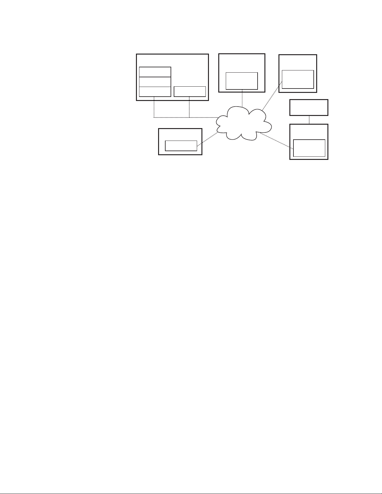
The Encore control system has a distributed, client/server architecture,
using standard Ethernet communications protocols (Figure 1). The Encore
system consists of client, server, and central core components. The central
core (Sharer, Database, System Manager) is required since all other components rely on its existence. An Encore OUI is also required since it is used
to configure the central core.
Kalypso Machine Control Interfaces Installation Instructions 9
Page 10
Section 1 — Machine Control Overview
Figure 1. Encore System Diagram
Kalypso Menu Panel
Encore Database
System Manager
Server Application
Different Applications
can run on
the same Engine
The same type of
Application can run on
different Engines
Sharer
Optional PC
Client Application
(Engine)
Encore OUI
Client Application
(Engine)
Encore OUI
Kalypso Video
Processor Frame
Encore
Machine Control
Client Application
Network
Ethernet
Profile VDR
(Engine)
VDRCS
Server
Application
VTR
Encore
Serial Engine
VSVC
Server
Application
Serial
Terms associated with an Encore system include:
Client — A generic term for a software component that makes use of a
service provided by a server. For Kalypso systems, Encore client software
is included in the core Kalypso software installed on the Video Processor
frame, enabling machine control capabilities (once the interfaces are
installed and configured).
Server — A generic term for a software component that provides a service
to a client. As a machine control example, the VDRCS software residing on
a Profile VDR acts as a server, because it provides a service (clip loading
and playback) to the client (the Kalypso system software).
8056_04_01_r0
System Manager — The software application used for overall system man-
agement functions, including logon, access control, and configuration. On
a Kalypso system it typically resides on the Menu panel, but it may reside
on any PC on the network.
Database — A data set containing configuration information used by the
various Encore system components.
Sharer — An Encore software component responsible for distributing the
database configuration data to the various applications as they boot up.
The Sharer also acts as a coordinator between the clients and servers.
OUI — The Encore user interface, a Windows based menu system. This is
considered a client for machine control and other functions.
Engine — A generic term for a hardware component with specific capabili-
ties. For example, a Profile VDR is considered an engine, as is the Menu
panel or PC on which the OUI application runs.
Application — A generic term for a software component that can be loaded
and run on an engine. For example, the VDRCS server application is
installed on the Profile VDR engine hardware, while the OUI client appli-
cation can be installed on the Kalypso Menu panel engine hardware.
10 Kalypso Machine Control Interfaces Installation Instructions
Page 11

Machine Control Support Software Installation
Machine Control Support Software Installation
What You Should Install
Encore Control System machine control software (formerly called
OmniBus software), used for external Profile and VTR device control via
the Kalypso system Machine Control subpanel, is included on the Kalypso
Software CD.
Sharer, System Manager, and Encore Operator User Interface (OUI) software can be installed on a Kalypso system using the Kalypso Install program. A Sharer and System Manager must be installed somewhere in your
facility to control a Profile or VTR with the Kalypso system, but only one
instance should be installed. Multiple versions of the Encore OUI can
safely reside on the network.
The Base Install includes a Port Mapper application, used to manage
system ports. This is installed regardless of which options are selected.
A default database is also included on the Kalypso Software CD, containing default IP addresses of Kalypso system and Profile devices. This
database is to be installed only one time, as a baseline to begin configuration, and should not be reloaded onto an existing operating system. Default
IP addresses will work if the Kalypso system and all the machine control
components reside on an isolated network. If the Kalypso system is interconnected with a facility’s local area network, however, the IP addresses in
the Encore data base will probably need to be changed.
The Sharer, Database, and all the Encore/Omnibus servers must reside on
the same subnet. The Encore system uses broadcast messages that do not
propagate through routers.
In facilities where more than one Kalypso Menu panel exists or where multiple Kalypso systems access the same devices, it is best to install the Encore
central core on a separate PC rather than on one of the Kalypso Menu
panels. Otherwise, shutting down the Kalypso Menu panel with the Encore
database may stop a Kalypso system from controlling the machines. The
installation procedure on a PC is the same as that used on a Kalypso Menu
panel (just insert the CD and follow the directions). If the core components
are not installed on a Kalypso Menu panel, an Encore OUI should also be
installed with the central core. This provides configuration access independent of a Kalypso Menu panel, which might be turned off or unavailable.
Kalypso Machine Control Interfaces Installation Instructions 11
Page 12
Section 1 — Machine Control Overview
Install Machine Control Support Software
1. Exit any open applications.
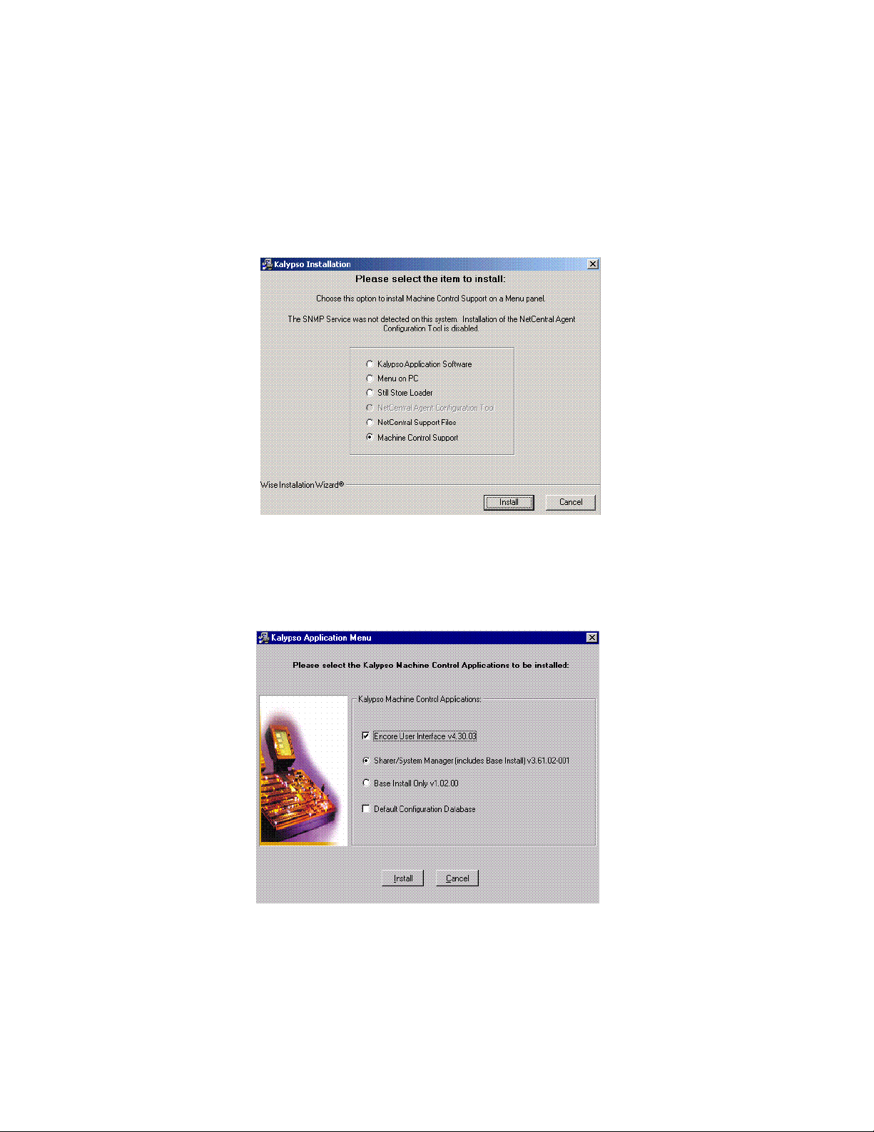
2. Insert the Kalypso Software CD. The following screen appears
(Figure 2).
Figure 2. Kalypso Install Screen 1
3. Select the Machine Control Support option, and then touch Install. The
Kalypso Application Menu appears (Figure 3).
Figure 3. Machine Control Installation Options Menu
12 Kalypso Machine Control Interfaces Installation Instructions
Page 13

Machine Control Support Software Installation
4. Select the appropriate installation options, as described in the
following bulleted paragraphs.
CAUTION Only one Sharer and System Manager is to be installed on a network.
• If you are installing machine control on your Kalypso system for
the first time and do not have an OmniBus facility management
system on the network, select Encore User Interface and Sharer/System
Manager and Default Configuration Data Base. Additional OmniBus or
Encore system configuration steps will also be required.
• If you are updating a Kalypso system already running a machine
control option and do not have an OmniBus facility management
system elsewhere on the network, select Encore User Interface and
Sharer/System Manager. The existing configuration will be retained.
CAUTION If updating existing Machine Control software on a Kalypso system, do NOT
choose the Default Configuration Database option, as it will overwrite the
existing configuration information.
• If you are updating a Kalypso system already running a machine
control option and have an Omnibus facility management system
running elsewhere on the network, select Encore User Interface and
Base Install Only. The existing configuration will be retained.
CAUTION If an existing OmniBus facility management system or an Encore control
system exists on the network, do NOT choose the Default Configuration Database option. If it is installed to the same location as the existing database, the
existing configuration information will be overwritten, disabling the OmniBus
or Encore system.
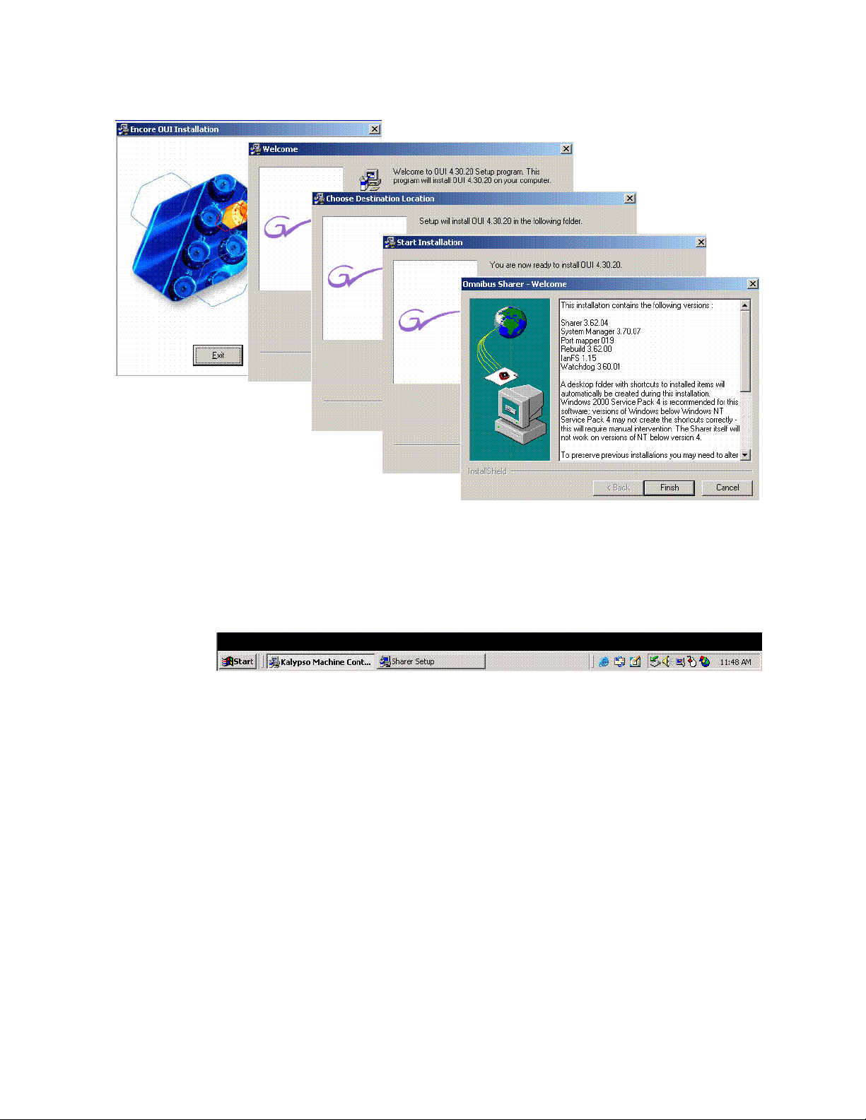
5. After making your selections, touch Install. During the subsequent
installation process several prompt and selection screens appear in
sequence. Different screens are displayed (Figure 4), depending on the
options originally chosen above. Carefully follow the on-screen
directions, and always use the default selection when choices are
offered.
Kalypso Machine Control Interfaces Installation Instructions 13
Page 14
Section 1 — Machine Control Overview
Figure 4. Machine Control Installation Screens
6. If you selected the Sharer/System Manager option, you may need to click
the Sharer Setup tab at the bottom of the screen (Figure 5) to bring up the
next menu.
Figure 5. Sharer Setup Tab
14 Kalypso Machine Control Interfaces Installation Instructions
Page 15
Machine Control Support Software Installation
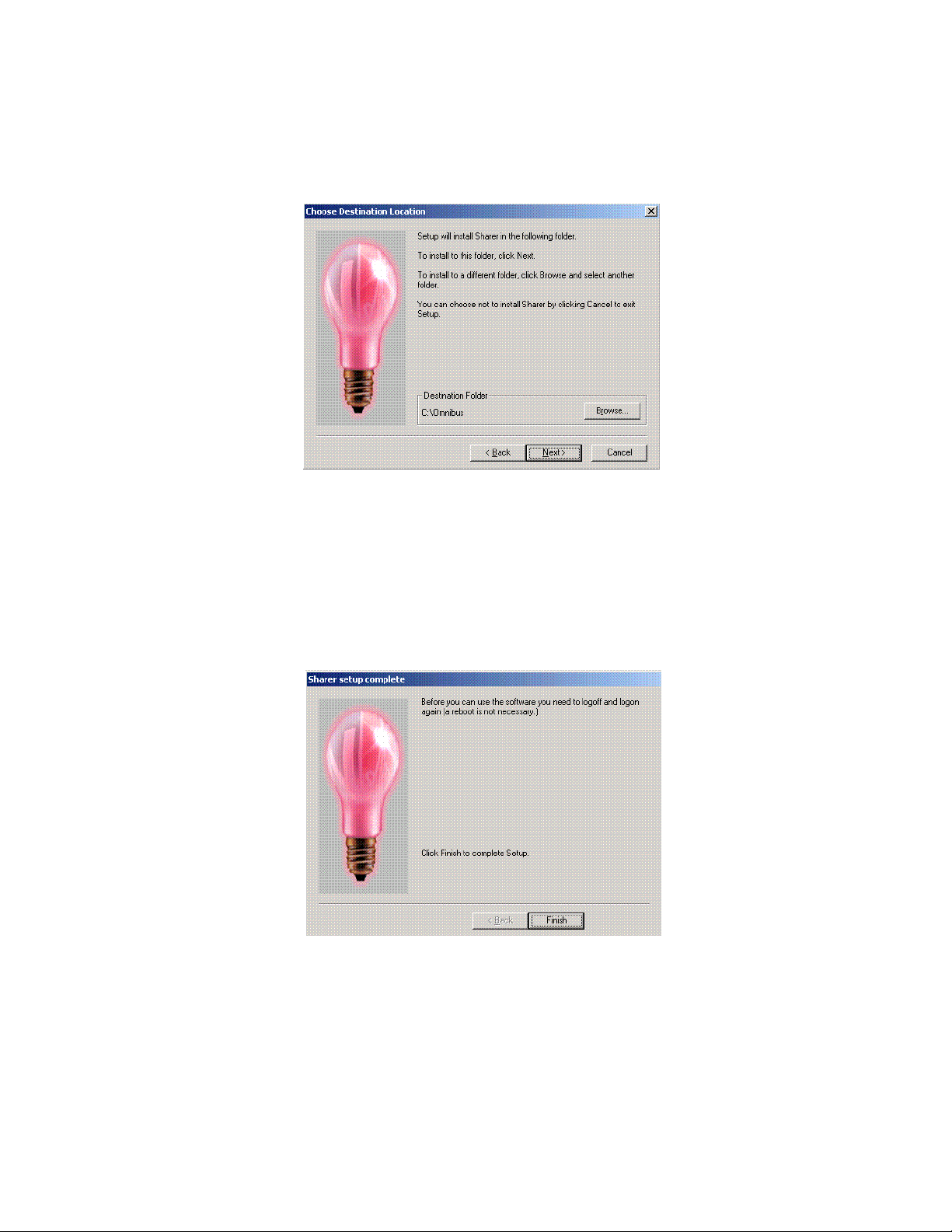
7. The Choose Destination Location screen appears next (Figure 6).
Choose the default.
Figure 6. Sharer Choose Destination Location Screen
8. If you installed the Sharer, after you complete the installation you will
need to log off and log on before you will be able to use the software,
as prompted on the following screen (Figure 7).
Note Do NOT log off at this time. You must first complete the Machine Control
Support Software installation. You will loggoff later at Step 11.
Figure 7. Sharer Install Logoff Message
Kalypso Machine Control Interfaces Installation Instructions 15
Page 16

Section 1 — Machine Control Overview
9. Touch the Finish button. The following prompt will appear (Figure 8).
Touch OK.
Figure 8. Completed Installation Prompt
10. If you upgraded existing machine control software and did NOT install
the default database, you must add a KAL user to the data base (see
Add User to Data Base on page 18). This is not necessary if the default
database was installed.
11. With the KAL user in the database, log off and back onto the computer.
Confirm Machine Control Support Installation
12. On startup the computer will load the Kalypso Menu application, as
usual, but the following applications also load:
• Encore User Interface
• SysMan3
• Portmapper
• Sharer (to exit Sharer you must first exit WatchDog)
• WatchDog (automatically reloads Sharer)
If you minimize the Kalypso Menu application, tabs for these applications will appear on the Windows task bar at the bottom of the screen.
16 Kalypso Machine Control Interfaces Installation Instructions
Page 17
Machine Control Support Software Installation
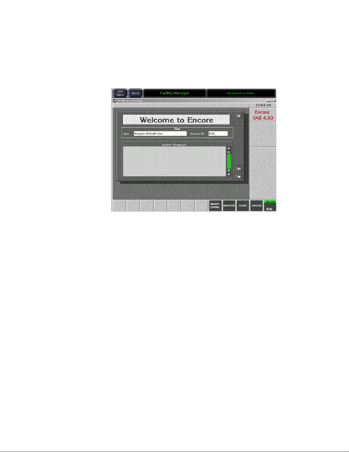
13. You will also be able to touch the Facility Manager button on the Kalypso
Menu panel to go directly to a logged on Encore User Interface screen
(Figure 9). This button is active after the entire Kalypso system has
completely booted up.
Figure 9.
Note The KAL logon has permissions for operational control only. To change con-
figuration settings you must log on as SYS.
14. You have completed the Machine Control Support software
installation. You can now go to Section 2 for Profile installation, or
Section 3 for VTR installation.
Kalypso Machine Control Interfaces Installation Instructions 17
Page 18
Section 1 — Machine Control Overview
Add User to Data Base
If the machine control installation was an upgrade that did NOT include
installation of the default database, the user KAL must be added to the data
base. This permits automatic logon to the Encore User Interface when the
Menu panel boots up.
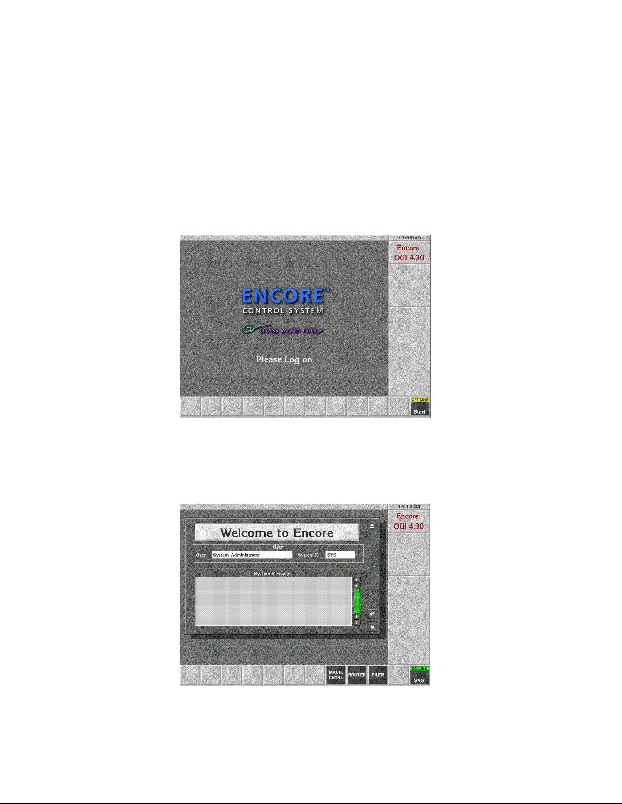
1. Touch the Facility Manager button on the Menu panel to bring up the
Encore User Interface (Figure 10). The button on the lower right of the
menu is labeled Start when not logged on.
Figure 10.
2. Click on the Start button and log on to the Encore GUI as user SYS
(Figure 11). SYS will appear in place of Start on the lower right button.
Figure 11.
18 Kalypso Machine Control Interfaces Installation Instructions
Page 19
Add User to Data Base
3. Close the Welcome window by clicking the button at the upper right
corner of its window.
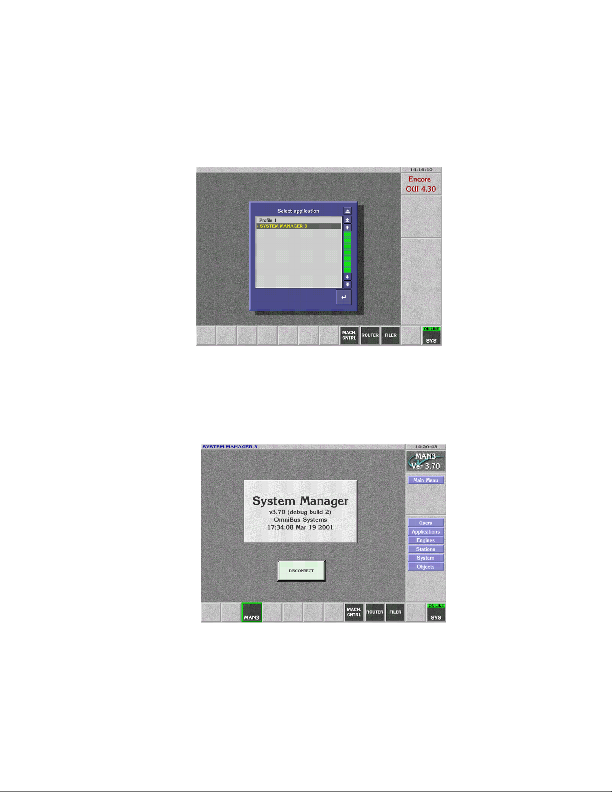
4. Click on an empty box on the task bar at the bottom of the screen. A list
of applications appears (Figure 12).
Figure 12.
5. Select the SYSTEM MANAGER 3 application and click the Return button
located at the lower right corner of the window. The System Manager
application screen appears (Figure 13).
Figure 13.
Kalypso Machine Control Interfaces Installation Instructions 19
Page 20
Section 1 — Machine Control Overview
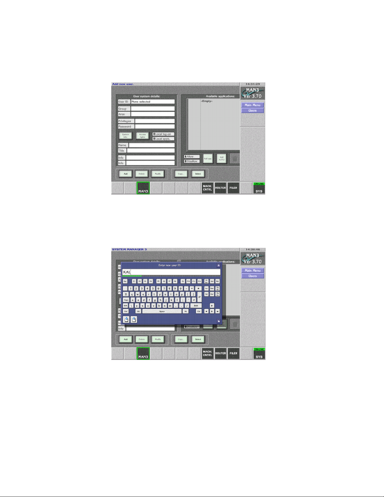
6. Select Users from the menu. The User System Details screen appears
(Figure 14).
Figure 14.
7. Select Add in the lower left corner of the screen. A prompt to Enter New
User ID appears. Enter KAL (Figure 15).
Figure 15.
20 Kalypso Machine Control Interfaces Installation Instructions
Page 21
Add User to Data Base
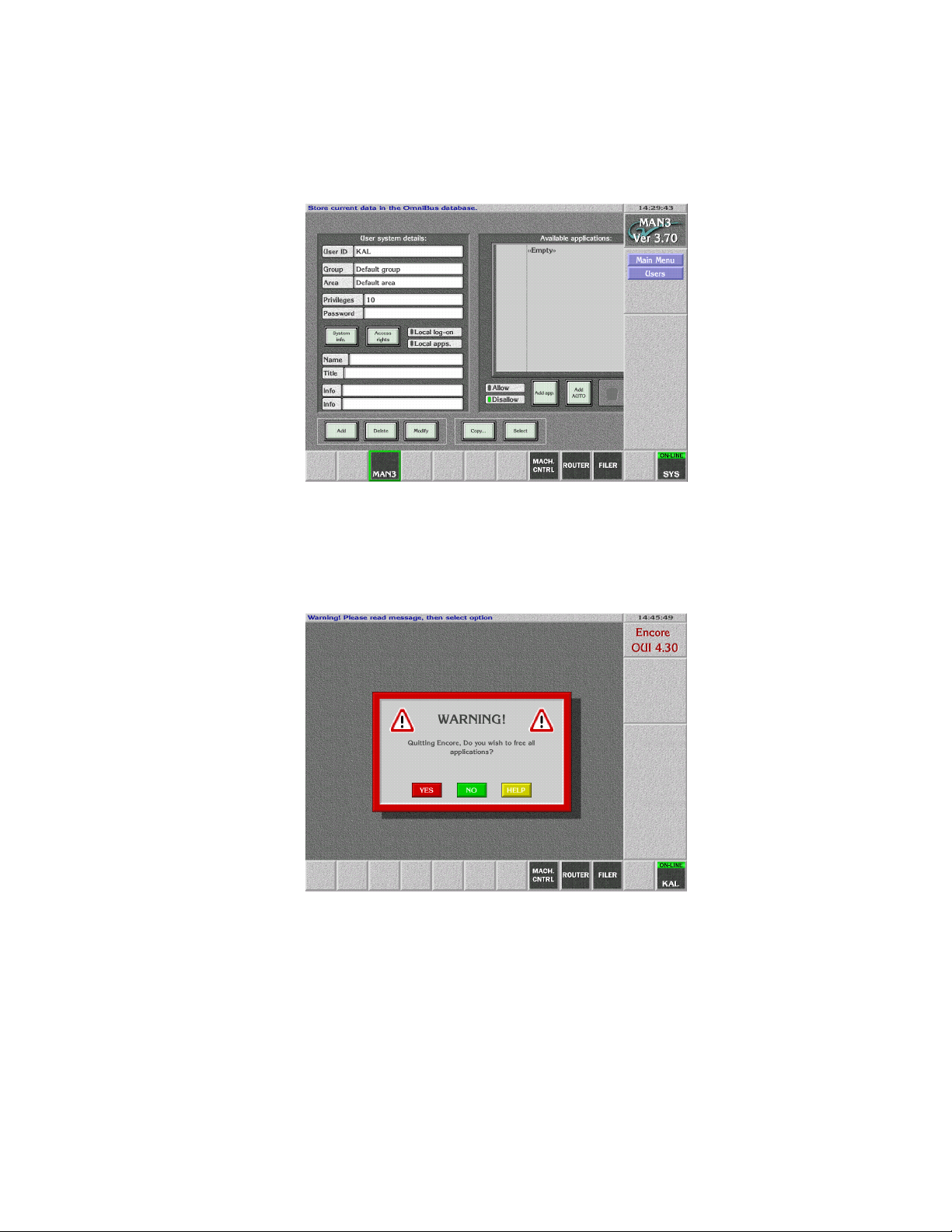
8. The User System Details screen re-appears. Click on the Modify button
(Figure 16).
Figure 16.
9. Click on the SYS button on the lower right and select YES to log off the
Encore User Interface (Figure 17).
Figure 17.
Kalypso Machine Control Interfaces Installation Instructions 21
Page 22
Section 1 — Machine Control Overview
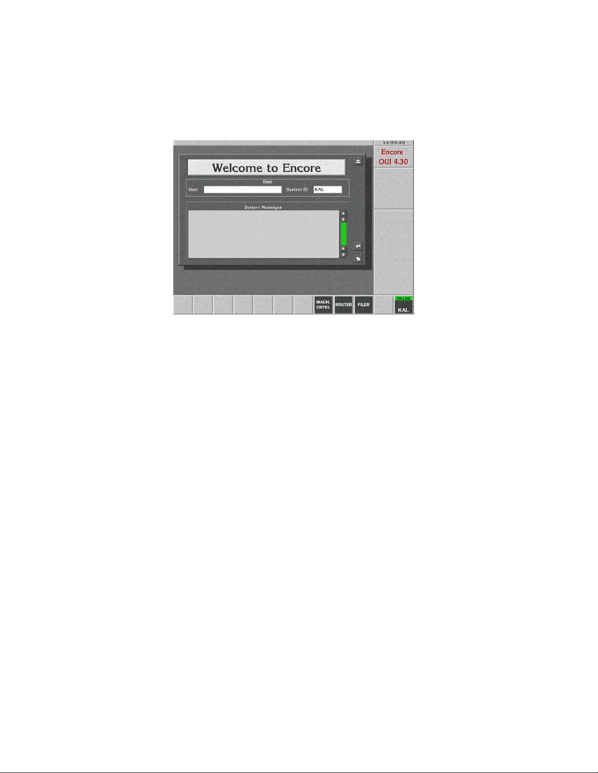
10. Click on the Start button and log on to the Encore GUI as user KAL to
test that the new user was added. The name KAL replaces Start on the
lower right button (Figure 18).
Figure 18.
Note The KAL logon has permissions for operational control only. To change con-
figuration settings you must log on as SYS.
11. If you are doing an initial Machine Control Support Software
installation, go back to Confirm Machine Control Support Installation on
page 16.
22 Kalypso Machine Control Interfaces Installation Instructions
Page 23

Encore IP Address Change Procedure
The default Encore database installed from the Kalypso software CD contains default IP addresses of the Kalypso system components and one
Profile VDR. These default addresses may need to be changed to support
larger installations. Changing these addresses when Encore has been
installed on the Kalypso Menu Processor involves the following steps:
• Run the Menu Processor and Encore under the old (default) address,
create copies, and change their IP addresses,
• Change the Menu Processor’s IP address to the new IP address,
• Restart Encore and delete the old IP addresses.
The following example procedure shows how to change from the default
addresses to the following new addresses (Table 1).
Table 1. IP Address Changes
Device Default Address New Address
Kalypso Menu 192.168.0.25 192.65.12.41
Kalypso Frame 192.168.0.20 192.65.12.21
Profile 192.168.0.10 192.65.12.58
Encore IP Address Change Procedure
You need a keyboard attached to the Main panel to perform this procedure.
To Modify Default Encore Database IP Addresses:
1. With Encore running (Sharer, System Manager and OUI), log on and
enter System Manager 3 application, User SYS, no password.
2. Engines. Select. Should see address 192.168.0.10 (the profile) and
192.168.0.25 (menu processor as host for system manager).
3. Build a copy of Profile if you want to change its address:
a. Add, IP Address: 192.65.12.58 (for this example, use your profile
IP address).
b. Name: Profile 1. (The names can be duplicated here, we are
going to delete the old names).
c. Copy, at popup, select 192.168.0.10 (the old profile), Modify
4. Build a copy of System Manager to run at the new IP address:
a. Add, IP Address: 192.65.12.41 (the new IP address of the
Kalypso menu processor).
b. Name: Kalypso Menu
c. Copy, at popup, select 192.168.0.25 (the old menu processor default
IP address), Modify
Kalypso Machine Control Interfaces Installation Instructions 23
Page 24

Section 1 — Machine Control Overview
5. Build a copy of the OUI to run at the new IP address.
a. Main Menu, Stations, Select. Should see addresses 192.168.0.20 (default
frame for the frame client) and 192.168.0.25 (default menu processor
for the OUI).
b. Add, IP Address: 192.65.12.41 (your new IP address for the
menu processor).
c. Name: Kalypso Menu.
d. Copy, at popup, select 192.168.0.25 (old menu address for OUI),
Modify
6. Create a new Frame Client for the new Frame IP address:
a. Add, IP Address: 192.65.12.21 (the new IP address of the
Kalypso Frame)
b. Name: Kalypso Frame
c. Copy, at popup, select 192.168.0.20 (the old default Kalypso frame
address), Modify
You should now have four entries in the stations/select popup:
192.168.0.20 (old frame address), 192.65.12.21 (new frame address),
192.168.0.25 (old menu processor address) and 192.168.12.41 (new
menu processor address). There should also be four entries in the
engines/select popup: 192.168.0.10 (old profile address), 192.65.12.58
(new profile address), 192.168.0.25 (old menu processor address) and
192.168.12.41 (new menu processor address).
7. Close Encore: stop OUI, sysman3 and Sharer.
8. Change IP address on the menu processor: my computer/Network/
TCP-IP/Properties. Enter 192.65.12.41. It is not necessary to reboot.
9. Restart Encore: start Sharer, Sysman3, and OUI.
10. Logon to Encore (user SYS, no password), enter application SYSTEM
MANAGER3.
11. Delete the engines and stations associated with the old IP addresses:
a. Engines, Select
b. Pick 192.168.0.10 (old Profile engine), Delete
c. Pick 192.168.0.25 (old Kalypso menu as host for manager engine),
Delete
d. Main Menu, Stations, Select
e. Pick 192.168.0.20 (old Kalypso frame host for frame client). Delete
f. Pick 192.168.0.25 (old Kalypso menu host for OUI). Delete
Encore should now be fully functional with the new addresses.
24 Kalypso Machine Control Interfaces Installation Instructions
Page 25

Saving Encore Machine Control Configurations
Saving Encore Machine Control Configurations
Machine Control configurations are separate from the Kalypso Engineering and Daily setups, and so are not backed up when those Kalypso
setup files are saved to disk. You can back up your current Machine
Control configuration to disk with the following procedure. This should be
done when you first install the Machine Control software and whenever
you change its configuration to avoid having to manually reconfigure the
system if the files are damaged or lost or a drive needs to be replaced.
Note This procedure is for systems where the Sharer application is installed on the
Kalypso Menu panel. Do not use this procedure if you are running Sharer on
a separate PC as part of an Encore concerto Routing system.
Backup Procedure
This procedure backs up the Encore Machine Control data base and configuration files. It also turns off logging and deletes log files, which can grow
large in size and eventually fill the available disk space.
1. Insert a Zip disk on which you wish to backup the files into the Kalypso
Zip drive.
2. On the Kalypso Menu panel, minimize the Kalypso Menu application
if necessary, then open Windows Explorer and go to the C: OMN
directory.
3. Turn off logging and delete any log files:
a. Open the SharerOptions.ini file.
b. Go to the heading [Logging].
c. Set RecordNetMessages = OFF
d. Set RecordRawCBNP = OFF
e. Close the file and save the changes.
f. Open the Omn/Logs directory and delete all the files in that directory,
leaving it empty.
4. Using Explorer, drag and drop the Omn folder to the Kalypso Zip drive.
You may want to first create a directory named with the date to save
the file in so you can store multiple configurations onto the same Zip
disk.
5. Remove the Zip disk, label it, and store it in a safe place.
Kalypso Machine Control Interfaces Installation Instructions 25
Page 26

Section 1 — Machine Control Overview
Restore Procedure
To restore the saved Machine Control configuration files, use Explorer to
drag the Omn folder from the Zip disk to the C: directory on the Menu
panel, overwriting any existing folder with that name.
Restore After Drive Replacement
If you replace a Kalypso Enhanced Menu panel, or replace the NT drive of
an Original Menu panel, you will need to reinstall the Machine Control
software, and then restore the configuration file.
Enhanced Menu Panel Restore
1. Close all operations on the Menu panel.
2. Insert the Kalypso Software CD and follow the standard procedure to
install the Machine Control Support software.
3. Insert the Zip disk that contains the backup Machine Control
configuration files.
4. Use Explorer to drag the Omn folder from the Zip disk to the C:
directory on the Menu panel, overwriting any existing folder with that
name.
5. Restart Windows NT.
Original Menu Panel Restore
1. Install the Kalypso Menu panel software using the standard procedure.
2. Install the Machine Control Support software using the standard
procedure.
3. Use Explorer to drag the Omn folder from the Zip disk to the C:
directory on the Menu panel, overwriting any existing folder with that
name.
4. Restart the Windows OS.
26 Kalypso Machine Control Interfaces Installation Instructions
Page 27

Uninstall Old Omnibus User Interface
Uninstall Old Omnibus User Interface
If the Kalypso system has previously been running an earlier version of
machine control, you can remove the older OmniBus User Interface if you
wish. While leaving the older OUI installed will not cause problems when
running the Encore User Interface, removing it prevents accidentally
loading the older version, which could cause confusion.
1. Go to Start\Settings\Control Panel\Add/Remove programs and
uninstall OUI.
2. If running Windows NT, delete the wincui icon from the desktop.
Windows 2000 should remove the icon automatically.
Reverting to Earlier Machine Control Software
If you wish to revert to an earlier version of machine control software, you
must uninstall the newer machine control version before installing the
older version.
1. Exit any open applications. You will need to exit Watchdog before you
can exit the Sharer.
2. Go to Start\Settings\Control Panel\Add/Remove Programs.
3. Uninstall the following items:
• Kalypso Machine Control
• OmniBus Sharer, or Base Install (which of these items is present
depends on the installation options selected)
• OUI
Note The machine control database cannot be removed with Add Remove. This is
intentional to prevent accidental loss of configuration data. If a new default
data base is installed, it will overwrite the existing flies located in C:\Omn.
4. Now install the older machine control software (OmniBus) using the
older Kalypso Software CD.
Kalypso Machine Control Interfaces Installation Instructions 27
Page 28

Section 1 — Machine Control Overview
28 Kalypso Machine Control Interfaces Installation Instructions
Page 29

Profile Interface
Introduction
The Profile interface software consists of:
• a VDRCS application (available as an option installed on the Profile
itself),
• a Sharer and a System Manager application, responsible for overseeing
the entire Encore control system network and to configure users and
their access to the network (provided on the Kalypso Software CD),
and
• a Port Mapper application (Base Install), used to manage system networking ports (provided on the Kalypso Software CD), and
• an Encore User Interface application (provided on the Kalypso Software CD).
Section 2
A Sharer and System Manager must be installed somewhere in your
facility to use Kalypso system machine control. However, only one
instance should be running on the network.
Kalypso Machine Control Interfaces Installation Instructions 29
Page 30
Section 2 — Profile Interface
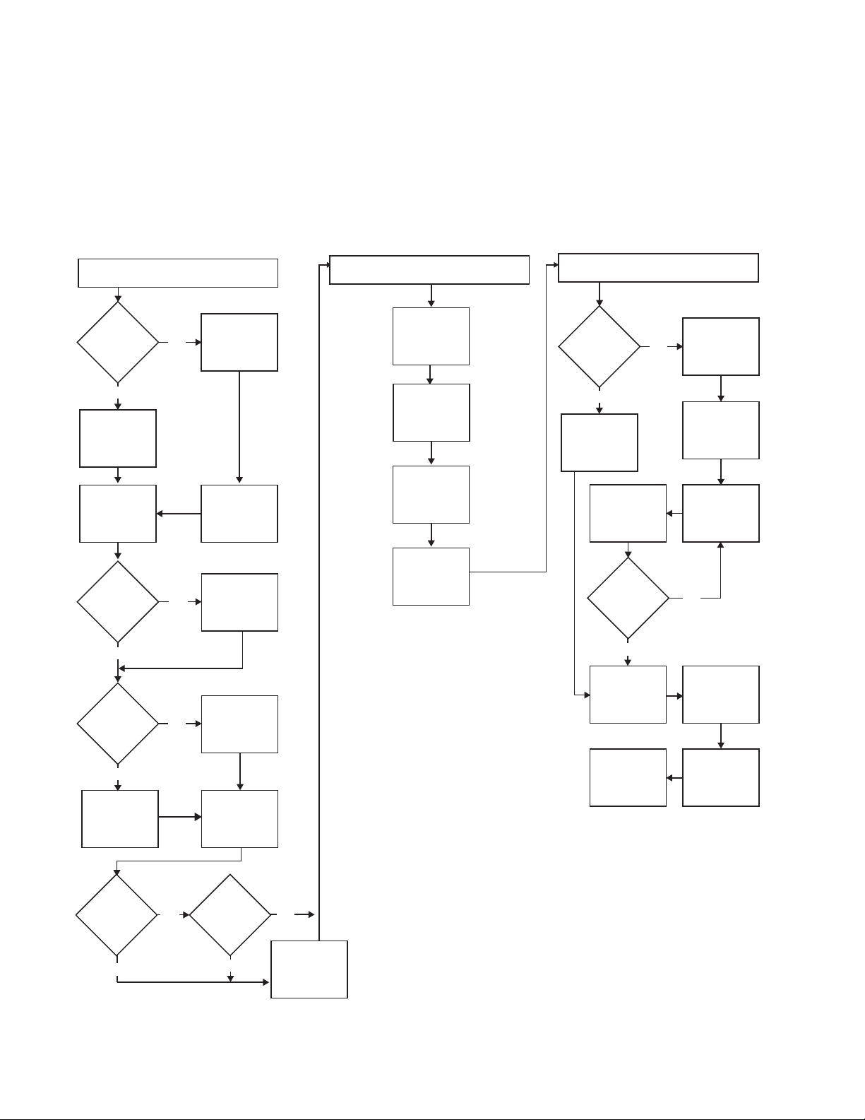
Overall Profile Configuration Procedure
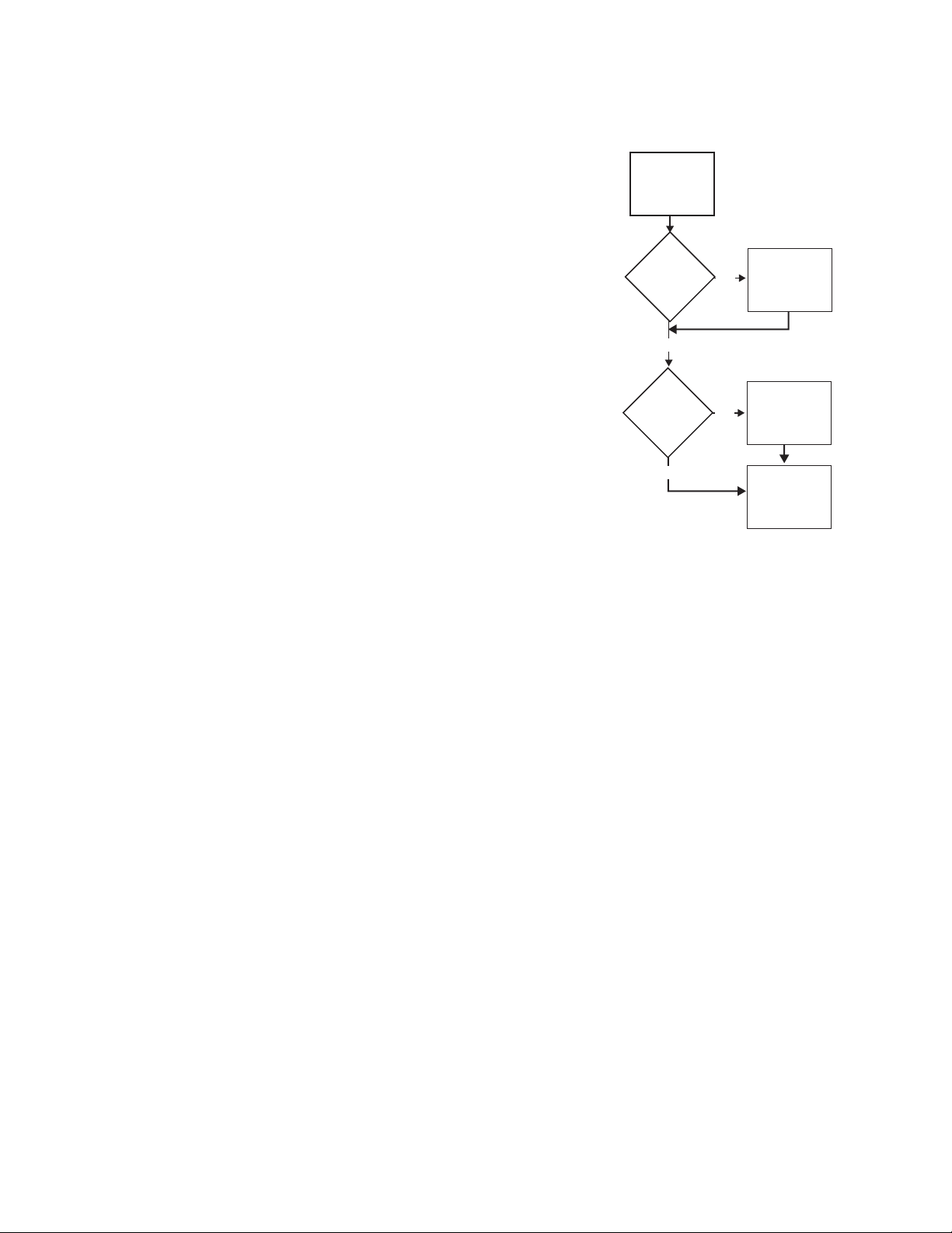
Interfacing a Profile VDR with the Kalypso system involves configuring
the Profile VDR itself, the Encore software, and the Kalypso system
(Figure 19). All three procedures must be completed in the order displayed.
Figure 19. Profile Interface Flow Diagram
Profile Installation and Configuration
Will
Only 1 Profile
be used?
(page 31)
NO
Unique Profile IP
Addresses
(page 31)
Kalypso Installation and Configuration
(page 40)
Install Machine
Control Support
Software
(page 12)
Only OUI
Software
Installed on
Kalypso?
Encore Configuration
(page 49)
NO
Access OUI and
Log In as SYS
(page 49)
YES
Default Profile IP
Address
(page 31)
Connect Profile
Ethernet to
Kalypso Switch
(page 31)
Old VDRCS
Installed?
NO
Does the
Profile have a
CD-ROM?
YES
Install VDRCS
from CD
(page 32)
YES
NO
List All IP
Addresses for
Later Use
Uninstall Old
VDRCS
(page 31)
Install VDRCS
over Network
(page 38)
Connect Profile
Video Outputs to
Kalypso Inputs
(page 40)
Create a New
Profile Device
Definition
(page 41)
Assign Profile
Devices to Kalypso
Sources
(page 45)
Map Each Source
to a Kalypso
Panel Button
(page 48)
YES
Contact OmniBus
for Information on
Configuring an
Existing System
Set Channel
Number and ID,
and Enable
(page 54)
All Profile
Channels
Configured?
YES
Save
Configuration
(page 55)
Test Kalypso
Profile Interface
Operation
(page 61)
Name Profile
Device and Set
Device Type
(page 54)
Select Port and
Set Profile API
(page 54)
NO
Confirm Device
Channel
Configuration
(page 57)
Test Playback
from OUI
(page 59)
Using
Fibre Channel?
NO
YES
Using
PLS 200?
YES
NO
Edit Batch File for
Fibre Channel or
PLS 200
(page 39)
30 Kalypso Machine Control Interfaces Installation Instructions
Page 31

Profile Installation and Configuration
A Profile VDR is controlled from the Kalypso system using the
KAL-IF-PROFILE option, which includes VDRCS software.
Profile Installation and Configuration
Default Profile IP Address
If only one Profile is involved, use its
default IP address.
Unique Profile IP Addresses
If more than one Profile will be used,
give each Profile a unique IP address.
Profile IP Addresses are changed
using standard Windows methods.
See the Profile Network Manual for specific information.
Connect Profile Ethernet to Kalypso Switch
The Kalypso system uses an Ethernet
Switch for system communications.
Connect the Profile VDR Ethernet port
to the Kalypso switch.
Profile Installation and Configuration
Will
Only 1 Profile
be used?
YES
Default Profile IP
Address
(page 31)
Connect Profile
Ethernet to
Kalypso Switch
(page 31)
Old VDRCS
Installed?
NO
(page 31)
NO
YES
Unique Profile IP
Addresses
(page 31)
List All IP
Addresses for
Later Use
Uninstall Old
VDRCS
(page 31)
Uninstall Old VDRCS
If an older version of VDRCS resides
Does the
Profile have a
CD-ROM?
NO
Install VDRCS
over Network
(page 38)
on the Profile, it should be removed.
1. Exit all applications on the Profile.
2. Go to Start\Settings\Control
Panel\Add/Remove programs
YES
Install VDRCS
from CD
(page 32)
Connect Profile
Video Outputs to
Kalypso Inputs
(page 40)
and uninstall Omni Base Setup and
VDRCS following all prompts.
3. Using Explorer, go to the C: drive
Using
Fibre Channel?
YES
Using
PLS 200?
NO
and delete the Omnibus folder.
4. Reboot the Profile.
NO
YES
Edit Batch File for
Fibre Channel or
PLS 200
(page 39)
Kalypso Machine Control Interfaces Installation Instructions 31
Page 32
Section 2 — Profile Interface
Install VDRCS from CD
If the Profile has a CD-ROM drive, install the software using that drive.
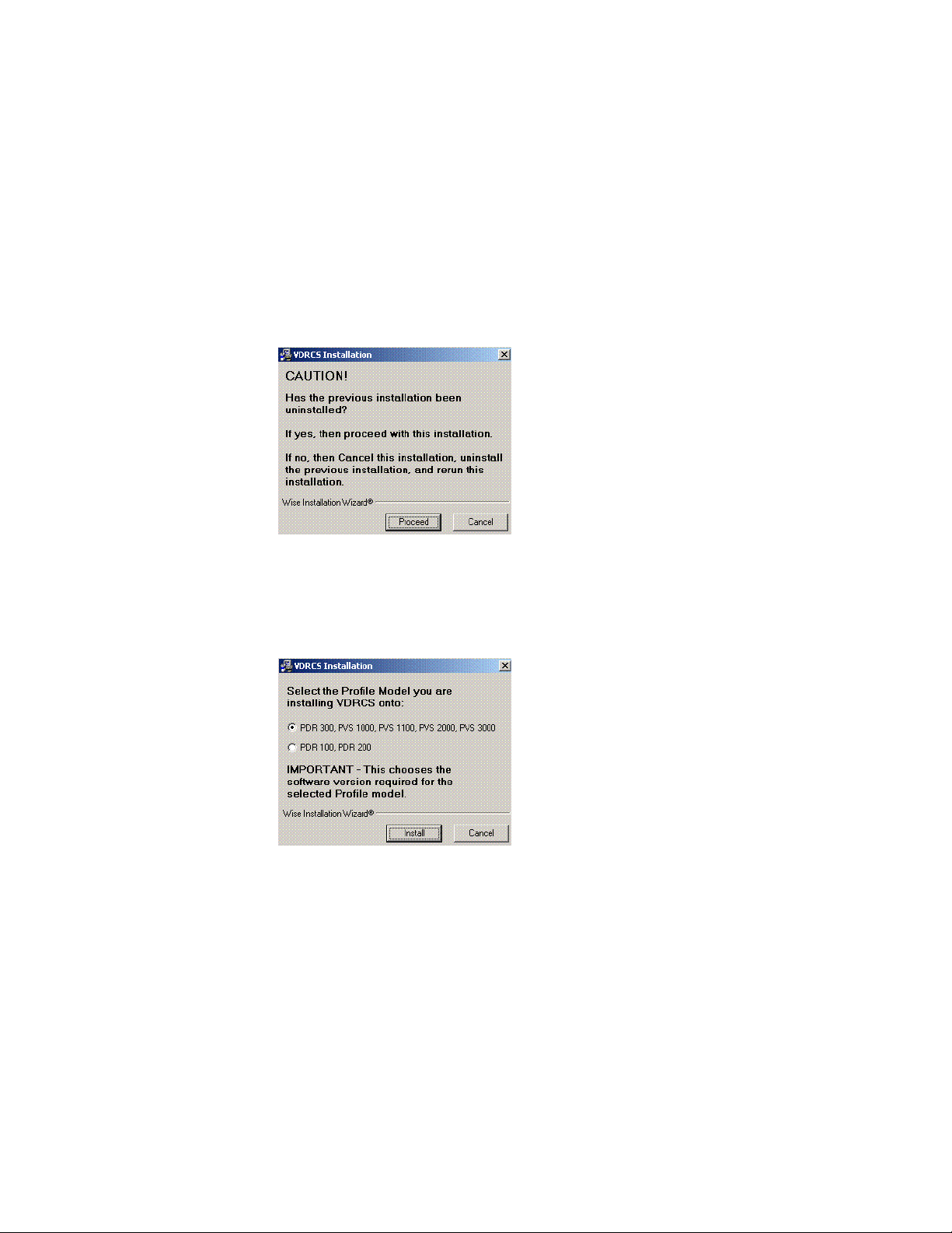
1. Exit any open applications.
2. Insert the KAL-IF-PROFILE CD into the CD-ROM drive of the Profile. The
installer program will launch automatically and a caution message is
posted reminding you to uninstall any previous instance of VDRCS, if
present (Figure 20). This is required to prevent installation problems.
Figure 20.
3. Click on Proceed (or Cancel and do the uninstall, described on page 31).
A Profile model selection screen is displayed (Figure 21).
Figure 21.
4. Select the Profile model you are installing onto and click Install. This is
important because it chooses the software version required for that
Profile model.
Note Later in the procedure you will be asked again for the Profile model, but that
later choice does NOT select different software. It only identifies the target of
the install. You must select the correct Profile model both times.
32 Kalypso Machine Control Interfaces Installation Instructions
Page 33

Profile Installation and Configuration
5. A Welcome window appears (Figure 22).
Figure 22.
6. Read the information and click Next>. A Read Me screen appears
(Figure 23).
Figure 23.
Kalypso Machine Control Interfaces Installation Instructions 33
Page 34
Section 2 — Profile Interface
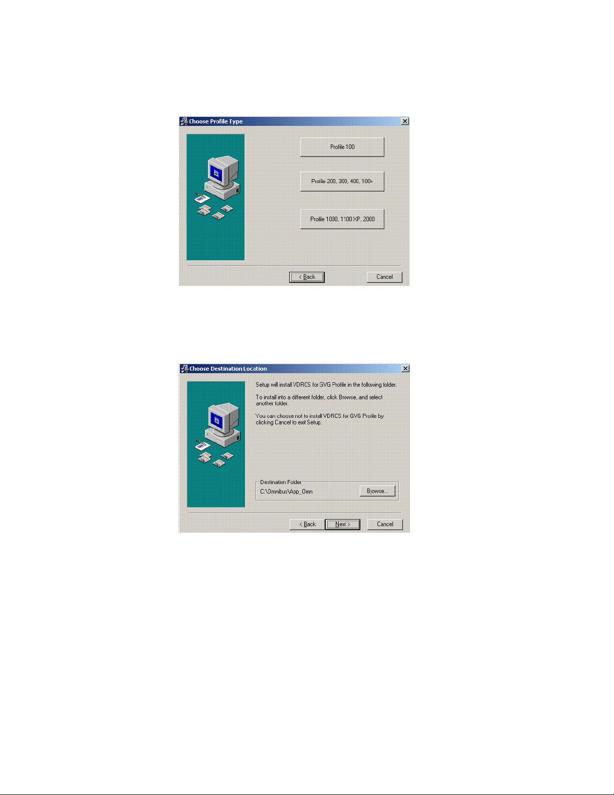
7. Click Next>. A Choose Profile Type screen appears (Figure 24).
Figure 24.
8. Once again select the Profile model you are installing VDRCS onto. A
Choose Destination screen appears (Figure 25).
Figure 25.
34 Kalypso Machine Control Interfaces Installation Instructions
Page 35

Profile Installation and Configuration
9. Select the default destination by clicking Next>. A Select Components
screen appears (Figure 26).
Figure 26.
10. The Profile model previously selected will be checked along with the
Omnibus Base Install. The App Fibre is also selected by default. If you
are not using Fibre channel you can uncheck this box. When done, click
Next>. The Program Manager Group screen appears (Figure 27).
Figure 27.
Kalypso Machine Control Interfaces Installation Instructions 35
Page 36

Section 2 — Profile Interface
11. Use the default group name and click Next>. A Start Installation screen
appears (Figure 28).
Figure 28.
12. Click Next>. Windows with progress bars appear and then an IP address
dialog is displayed (Figure 29).
Figure 29.
36 Kalypso Machine Control Interfaces Installation Instructions
Page 37

Profile Installation and Configuration
13. Click OK to use the default IP address displayed for the Encore network.
A Sharer Name screen appears (Figure 30).
Figure 30.
14. Enter the exact name or IP address of the computer running the Sharer
application and Click Next>. (The Sharer computer on many Kalypso
systems is the Menu panel). A progress bar will run, and an Omnibus
Base Setup screen appears (Figure 31).
Figure 31.
Kalypso Machine Control Interfaces Installation Instructions 37
Page 38

Section 2 — Profile Interface
15. Keep the Yes restart computer option selected and click OK. A finish
screen appears briefly and then the computer restarts (Figure 32).
Figure 32.
16. If you chose No above, click Finish.
17. Remove the VDRCS CD from the Profile’s CD-ROM drive and store it
in a safe place.
18. Reboot the Profile to complete the installation.
You now must continue with the installation and configuration procedures
for the Kalypso and Encore systems.
Install VDRCS over Network
If the Profile does not have a CD-ROM drive, software can be installed over
the network.
A standard PC with a CD-ROM can be connected to the network for this
purpose, or
1. If necessary, set up the Profile to communicate over the network, using
the Windows controls at Start\Settings\ControlPanel\Network.
2. The Kalypso system CD-ROM can be used, which should already be
configured on the network. Alternatively, you can use any PC with a
CD-ROM drive, but it will need to be configured and connected to the
network. In either case, the devices must be in the same Windows
Workgroup.
3. Insert the KAL-IF-PROFILE CD into the CD-ROM drive of the Kalypso
system or PC connected to the network. You will need to know the
name of the computer and the path to reach it over the network.
38 Kalypso Machine Control Interfaces Installation Instructions
Page 39

Profile Installation and Configuration
4. Share the disk in the CD drive of the PC:
a. Double click on My Computer and select the CD drive (generally D: or
E:)
b. Select File, Sharing.
c. Click on Shared As.
d. Enter a share name, for example KAL_CD.
e. Click on Permissions and select Everyone, Full Control.
f. Click OK, and click OK again.
5. On the Profile, use Network Neighborhood to navigate to the PC with
the shared drive.The default name for the Kalypso Menu panel is
Kalypsomenu1. If prompted for a name and password, enter the name
KALYPSO and the password kalypso (must be lower case).
6. Open the drive and run the Install from CD procedure as described on
page 32.
7. If you have multiple Profiles on the network, go to each one in turn and
repeat Step 5.
8. Remove the CD from the PC and store it in a safe place.
Edit Batch File for Fibre Channel or PLS 200
During installation a batch file is installed on the Profile for setting Fibre
Channel and PLS200 operation. The defaults are Fibre Channel ON and
PLS200 OFF. If you are not using Fibre Channel, or have a PLS 200
installed, the c:\omnibus\app_omn\AppStart.bat batch file will need to be edited.
1. Make the batch file editable:
a. Right click on AppStart.bat and select Properties.
b. Uncheck the Read only attribute and click OK.
2. Open the file in Notepad for editing by right clicking on AppStart.bat and
selecting Edit.
3. If you will not be using Profile Fibre Channel clip transfers, add REMs
to the following section:
REM echo Starting App_Fibre . . .
REM start "OmniBus Fibre" /D\OmniBus\App_Omn\!App_Fibre\ /MIN \OmniBus\App_Omn\!App_fibre\App_Fibre.exe
4. If the Profile is connected to a PLS200 remove the REMs from the
following section:
Kalypso Machine Control Interfaces Installation Instructions 39
Page 40

Section 2 — Profile Interface
echo Starting App_PLS . . .
start "OmniBus PLS" /D\OmniBus\App_Omn\!App_PLS\ /
MIN \OmniBus\App_Omn\App_PLS.exe
5. Save the modified batch file.
Connect Profile Video Outputs to Kalypso Inputs
The video outputs of each Profile channel being used are attached to
Kalypso Input module connectors. List the Kalypso Input module number
and J connector number for each connection for later use when configuring
the Kalypso system sources. The order of the channels (1, 2, 3, etc.) will
match the names of the Device Definitions.
Kalypso Installation and Configuration
Kalypso Installation and Configuration
(page 40)
Install Encore Software
If you have not already done so, install the
appropriate Encore software using the
Kalypso Software CD (see Machine Control
Support Software Installation on page 11).
Note If you have Omnibus already running at
your facility, then do not install it on the
Kalypso system. Similarly, if you have
more than one Kalypso system on the
network, then the Sharer and System
Manager should be loaded on only one of
these systems.
You now need to configure the Kalypso
system to recognize the Profile for
machine control.
Install Machine
Control Support
Software
(page 12)
Create a New
Profile Device
Definition
(page 41)
Assign Profile
Devices to Kalypso
Sources
(page 45)
Map Each Source
to a Kalypso
Panel Button
(page 48)
40 Kalypso Machine Control Interfaces Installation Instructions
Page 41

Create a New Profile Device Definition
1. Log on as the EIC so you can change the Eng Setup configuration
(touch Daily Setups, EIC Login).
2. After logging on, go to the Eng Setup Port & Device Definition menu
(touch Eng Setup, Ports & Devices). A menu similar to Figure 33 is
displayed.
Figure 33. Port & Device Definition Menu
Kalypso Installation and Configuration
Kalypso Machine Control Interfaces Installation Instructions 41
Page 42

Section 2 — Profile Interface
3. Touch New Device in the Edit Device List pane, then select DDR as the
Device Type (Figure 34).
Figure 34. Device Definition Data Entry Menu
4. Touch the Device Name data pad and enter the name you wish to use to
identify the device.
a. Enter Profile1-1 (no space with dash) for the first channel of a
multiple channel Profile system.
CAUTION The Profile Device Name entered here must exactly match the name used by
the Encore system for that Profile channel. The names above are commonly
used when an Encore system is configured, but may be different at your
facility.
b. Touch the Create button on the lower right. The next menu will
appear.
42 Kalypso Machine Control Interfaces Installation Instructions
Page 43

Kalypso Installation and Configuration
5. Touch the Ethernet Address data pad and enter its exact value (default
Profile VDR address is 192.168.0.10). Figure 35 shows the menu after
the name and IP Address have been entered.
Figure 35. Device Definition Menu with Profile Data
Kalypso Machine Control Interfaces Installation Instructions 43
Page 44

Section 2 — Profile Interface
6. Repeat this process for every channel of that Profile VDR, incrementing
the number by one for each. A four channel configuration is shown in
Figure 36.
Figure 36. Device Definition Menu with Four Channel Profile Configuration
44 Kalypso Machine Control Interfaces Installation Instructions
Page 45

Assign Profile Devices to Kalypso Sources
1. Touch the Source Definition category selection button at the bottom of the
screen. Select the Engineering source on the scrolling list, name the
source with the Engineering Name data pad, select the input
number(s), and enter any keying information.
2. Touch the Device Source Type button. The Device datapad below
activates (Figure 37).
Figure 37. Source Definition Menu, Available Devices
Kalypso Installation and Configuration
Kalypso Machine Control Interfaces Installation Instructions 45
Page 46

Section 2 — Profile Interface
3. Touch the Device data pad in the new window. A menu similar to
Figure 38 is displayed.
Figure 38. Source Definition Menu, Available Devices
4. Touch the name button of the desired defined device. This assigns that
device for control by that selected source and the previous menu is then
displayed.
46 Kalypso Machine Control Interfaces Installation Instructions
Page 47

Kalypso Installation and Configuration
5. Repeat the steps above to name each additional Kalypso source as a
Profile channel, select the input, and assign the appropriate device.
These sources are now defined as Profile VDR channels, as shown in
Figure 39.
Figure 39. Source Definition Menu, Devices Assigned
Kalypso Machine Control Interfaces Installation Instructions 47
Page 48
Section 2 — Profile Interface
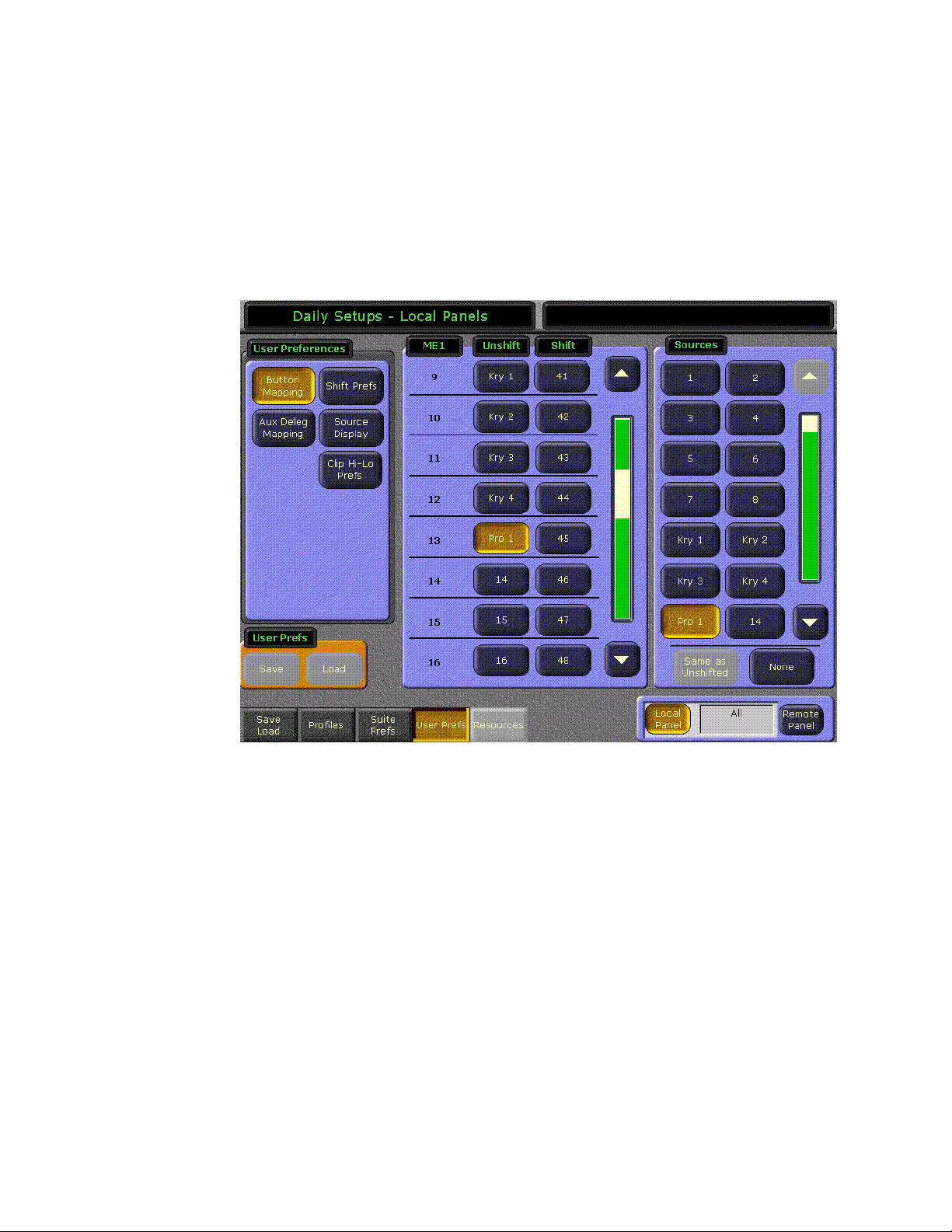
Map Each Source to a Kalypso Panel Button
1. Go to the Button Mapping menu by touching the Daily Setups button on
the Menu panel, then press User Prefs and Button Mapping buttons.
2. Assign each Profile VDR source from the right scrolling pane to the
desired menu button on the left scrolling pane (Figure 40).
Figure 40. Button Mapping Menu with Profile Sources Assigned
Save Kalypso Configuration Files
You should now save the Kalypso Engineering Setup file and User Prefs
files that contain the new machine control settings. This is accomplished
from the Save Load menu for Eng Setup, and the separate Save Load menu
for Daily Setups. Refer to the separate Kalypso User Manual for specific
instructions.
Note If after testing the interface, changes must be made to the Kalypso settings,
remember to save the modified Eng Setup and User Prefs configuration files.
48 Kalypso Machine Control Interfaces Installation Instructions
Page 49

Encore Configuration
Encore Configuration
Configure Encore Software for Profile
After VDRCS has been installed on a Profile
VDR, the Encore software itself must be
configured using the Encore OUI. The following procedure assumes the Encore software and default database were properly
installed onto a Kalypso system using the
Kalypso software CD. For more detailed
information about configuration, refer to
the Encore end user documentation.
Access OUI and Log In as SYS
1. Make sure that the Kalypso Menu panel
and Profile are both connected to the
network and that their IP addresses are
on the same subnet.
Encore Configuration
Only OUI
Software
Installed on
Kalypso?
YES
Contact OmniBus
for Information on
Configuring an
Existing System
Set Channel
Number and ID,
and Enable
(page 54)
All Profile
Channels
Configured?
YES
(page 49)
NO
Access OUI and
Log In as SYS
(page 49)
Name Profile
Device and Set
Device Type
(page 54)
Select Port and
Set Profile API
(page 54)
NO
2. Press the Facility Manager button on the
Kalypso Menu panel to go to the Encore
OUI (Figure 41).
Note Do not use the older wincui icon, if still
present on your system.
Save
Configuration
(page 55)
Test Kalypso
Profile Interface
Operation
(page 61)
Confirm Device
Channel
Configuration
(page 57)
Test Playback
from OUI
(page 59)
Kalypso Machine Control Interfaces Installation Instructions 49
Page 50
Section 2 — Profile Interface
Figure 41. Encore Welcome Message. KAL Login
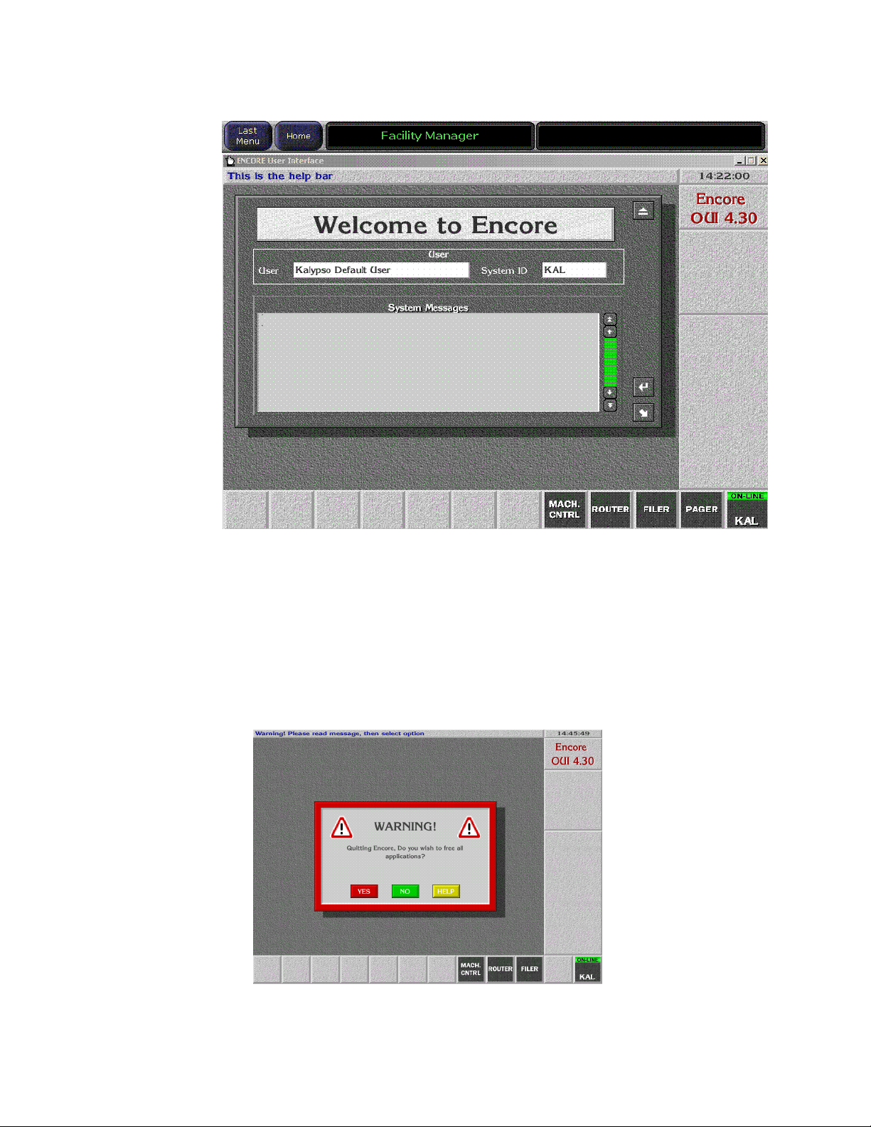
3. Click the button on the lower right corner of the menu labeled either
Start (not logged in) or with the login name (KAL is the default shown in
Figure 41). You may need to drag the window up to see the buttons.
4. If logged in as KAL the warning message shown in Figure 42 appears.
Select YES to log off, then click on the OFF LINE button on the lower
right.
Figure 42. Logoff Warning Message
50 Kalypso Machine Control Interfaces Installation Instructions
Page 51

Encore Configuration
5. A popup keypad will appear next. Type SYS and press the Enter key (no
password required). Logging in as the system administrator ensures
you have full permissions for configuration changes. A Welcome
dialog will appear, with SYS identified on the lower right button
(Figure 43).
Figure 43. Encore Welcome Message, SYS Login
6. Close the Welcome to Encore screen by clicking on the upper right
triangle symbol Eject box on its own window (do not use the Windows
minimize or close boxes).
Kalypso Machine Control Interfaces Installation Instructions 51
Page 52

Section 2 — Profile Interface
7. Click on an empty box on the task bar at the bottom of the screen. A
Select Application pane appears with a list of applications (Figure 44).
Figure 44. Encore Select Application Window?
52 Kalypso Machine Control Interfaces Installation Instructions
Page 53

Encore Configuration
8. Select Profile 1 by double-clicking on it, or click on it once and then click
on the large angle arrow Enter button on the lower right of the selection
window. The VDR Cue Service menu will appear (Figure 45).
Figure 45. Encore VDR Cue Service Menu
Kalypso Machine Control Interfaces Installation Instructions 53
Page 54

Section 2 — Profile Interface
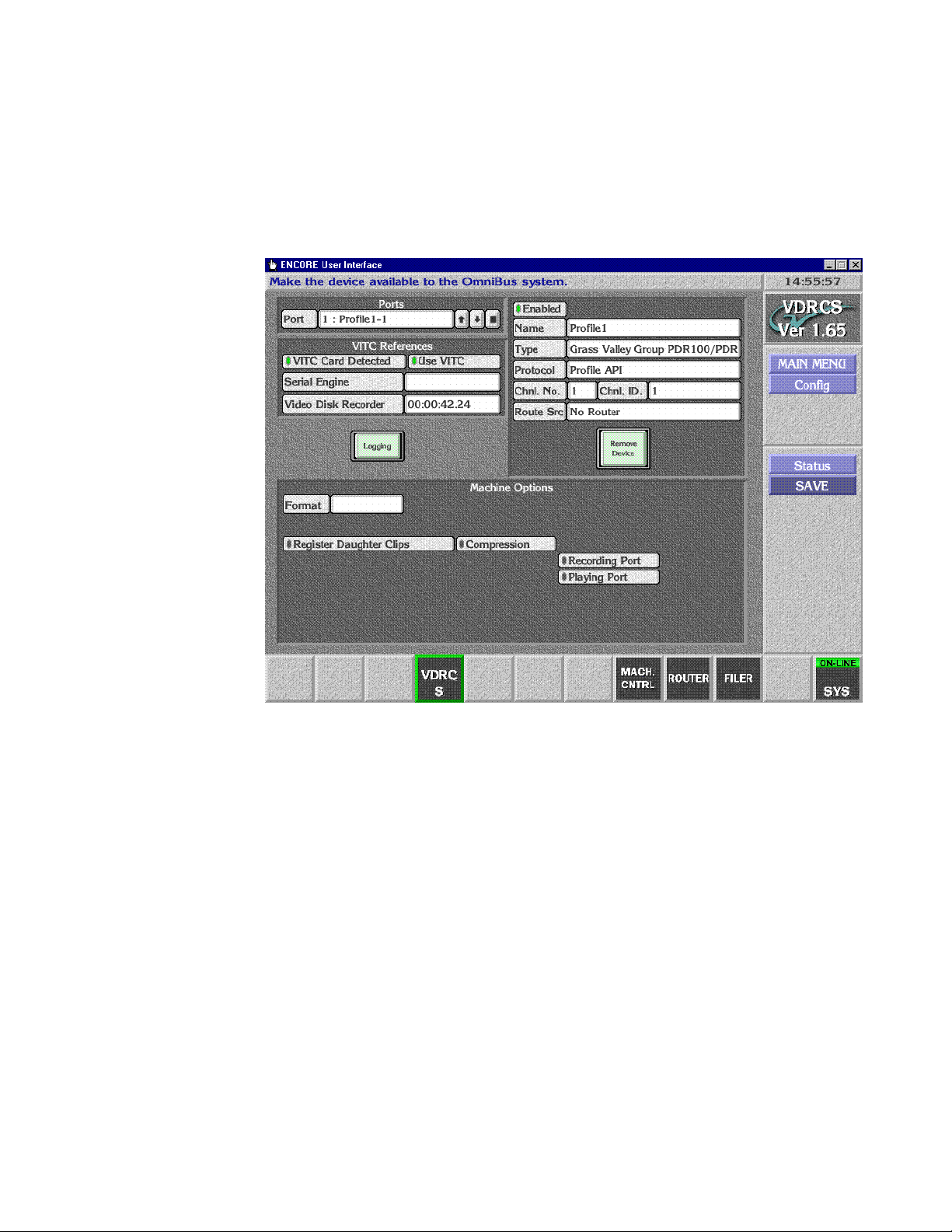
9. Select Config on the task bar on the right. A configuration window will
appear (Figure 46).
Figure 46. Encore Profile Device Configuration Window
Name Profile Device and Set Device Type
10. Click on the Name field, backspace over any existing characters and type
Profile1 (no space) and then press the Enter key.
11. Set the Type field to Profile PDRx00 (depending on which type of Profile
you are using).
Select Port and Set Profile API
12. Click on Port on the upper left corner of the screen and choose the port
number. Choose Port 1 to start, then click on the angle arrow Enter
button.
13. Set the Protocol field to Profile API.
Set Channel Number and ID, and Enable
14. Set the Chnl. No. field for the Profile channel. Use 1 for the first Profile
channel.
54 Kalypso Machine Control Interfaces Installation Instructions
Page 55
Encore Configuration
15. Set the Chnl. ID field for the Profile channel. Use 1 (back space over any
existing characters) for the first Profile channel.
16. Enable that channel by selecting the small box above the name field so it
is green. Your menu should then look like Figure 47.
Figure 47. Encore Profile Device with Configuration Data
17. Repeat Step 12 through Step 16 for the other channels, incrementing
the Port, Channel No, and Channel ID values. The Name, Type, and
Protocol fields should be the same for all the channels on that Profile.
Save Configuration
18. Click on SAVE on the right to save configuration for all the channels. A
confirmation message box will appear over the window.
19. Click on the message box to close it.
Test Lower Level Control
You can now test communication and control to the Profile using VDRCS.
This test uses the Profile’s Native Protocol and does not use the Encore
Machine Control configuration settings.
Kalypso Machine Control Interfaces Installation Instructions 55
Page 56

Section 2 — Profile Interface
20. Click on MAIN MENU, then click on the Control item on the right. A menu
will appear for the Profile channel that was last selected (Figure 48).
Figure 48. VDRCS Control Menu
21. Click LOAD and choose a clip from the list of recorded clips.
22. Select that Profile source on a PVW bus on the Kalypso switcher so its
image can be seen on a monitor.
Note Do not use the PGM bus, because when the device is on-air it cannot be con-
trolled from another location.
23. On the VDRCS menu (not the Kalypso Main panel), click on the play
and stop buttons to roll and stop the clip and view the monitor to
confirm that control at this level exists.
24. Exit VDRCS by clicking on the MAIN MENU item on the right task bar,
then clicking on the Disconnect message box.
56 Kalypso Machine Control Interfaces Installation Instructions
Page 57

Test Configuration and Operation
With VDRCS installed and the Kalypso and Encore systems configured,
you should have machine control from the Kalypso Main panel. Source
buttons mapped to devices should no longer have a ? status indicator.
If control is not working properly, you can use the following procedures to
test whether the problem resides on the Encore system or the Kalypso
system.
Confirm Device Channel Configuration
1. Access the Local Machine Control Panel by touching the MACH CNTRL button
on the lower task bar. A screen like Figure 49 will appear.
Figure 49. Encore Local Machine Control
Test Configuration and Operation
Kalypso Machine Control Interfaces Installation Instructions 57
Page 58
Section 2 — Profile Interface
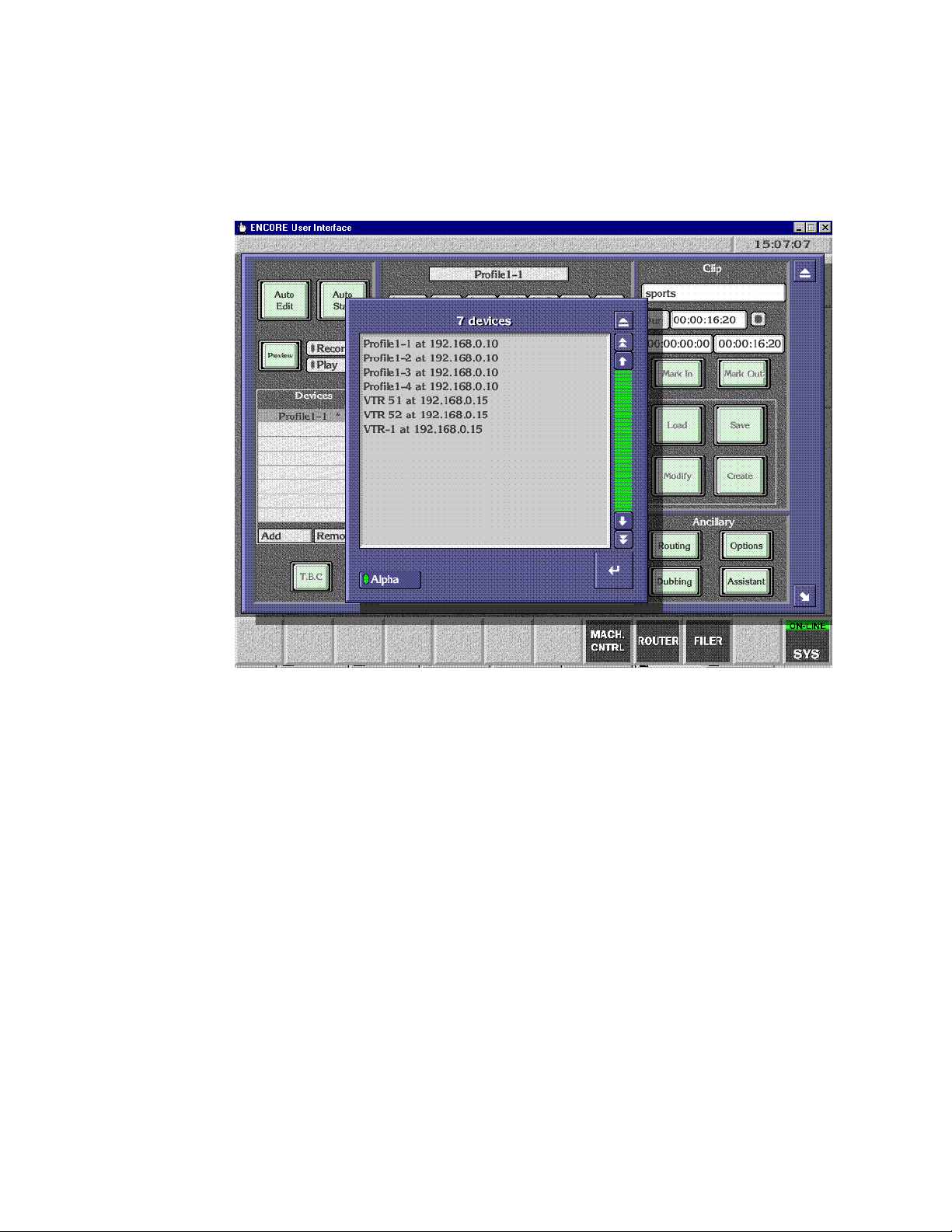
2. Click on ADD on the left side of the screen. A list including multiple
Profile devices with the same IP address should appear. Figure 50
assumes a 4-channel Profile has been configured.
Figure 50. List of Configured Encore Devices
58 Kalypso Machine Control Interfaces Installation Instructions
Page 59

Test Playback from OUI
You can now test that the Profile can be controlled directly with the Encore
User Interface.
3. From the list shown on Figure 50 on page 58, select one of the Profile
devices and click on the Enter button on the lower right of the devices
list. This selects one of the devices for local control on the Machine
Control menu (Figure 51).
Figure 51. Profile Selected for Encore Local Control
Test Configuration and Operation
Kalypso Machine Control Interfaces Installation Instructions 59
Page 60

Section 2 — Profile Interface
4. Click on the Options button on the lower right to open a clips menu, and
make sure the List Loading option has been selected. This ensures you
can load clips residing on the Profile (Figure 52).
Figure 52. Encore List Loading Option
5. Close the clips menu, then click on the Load button on the middle right.
If clips have been recorded on the Profile a list of these clips will
appear. Select one to play.
60 Kalypso Machine Control Interfaces Installation Instructions
Page 61

Test Configuration and Operation
6. Click on the Play symbol button in the center of the screen. Timecode
should advance while the clip plays (Figure 53), demonstrating that
machine control exists.
Figure 53. Encore Profile Clip Playback
Test Kalypso Profile Interface Operation
Test that the Profile can be controlled directly with the Kalypso Machine
Control subpanel.
• Select a Profile channel to control on the PGM PST B bus (or whatever
bus has been delegated),
• Scroll through a list of available Profile clips, viewing their names on
the readout,
• Cue and load a selected clip, and
• Play, Stop, Fast Forward, and Rewind the loaded clip.
You have now completed the Profile interface installation and configuration for Kalypso control.
Note You should now back up the Encore configuration files (see Saving Encore
Machine Control Configurations on page 25).
Kalypso Machine Control Interfaces Installation Instructions 61
Page 62

Section 2 — Profile Interface
62 Kalypso Machine Control Interfaces Installation Instructions
Page 63

VTR Interface
Introduction
The Kalypso system can be interfaced to control VTRs, using the Encore
control system.
Encore VTR Interface Components
The VTR interface components consist of:
• Serial Control Engine hardware running the Acorn OS, and capable of
controlling up to six VTRs,
• VSVC application software (provided on two specially formatted
floppy disks, used for installation on the Serial Control Engine),
Section 3
• a Sharer/System Manager application, responsible for overseeing the
entire Encore network and to configure users and their access to the
network (provided on the Kalypso Software CD),
• a Port Mapper application (Base Install), used to manage system networking ports (provided on the Kalypso Software CD), and,
• an Encore OUI (Operator User Interface) application, (provided on the
Kalypso Software CD).
A Sharer and System Manager must be installed somewhere in your
facility to use Kalypso system machine control. However, only one
instance should be running on the network.
Required Materials
You will need the following additional materials and signals to install the
VTR interface:
• Black Burst with house VITC
• Category 5 Ethernet cable
• RS-422 Serial cable (9-pin for ports 1-4)
Kalypso Machine Control Interfaces Installation Instructions 63
Page 64

Section 3 — VTR Interface
Note Serial Engine ports 5 and 6 have a single 44 pin connector. See the OmniBus
Serial Engine documentation for pinout information.
You will also need the following additional materials if you are not using
default Kalypso and Serial Engine configurations:
• VGA Monitor
• PC keyboard (European or American)
• Mouse (3 button required; left, right, and center presses may be
needed)
64 Kalypso Machine Control Interfaces Installation Instructions
Page 65

Overall VTR Configuration Procedure
Interfacing a VTR with the Kalypso system involves configuring the Serial
Engine itself, the Encore software used for system integration, and the
Kalypso system (Figure 54). All three procedures must be completed in the
order displayed in the flow diagram.
Figure 54. VTR Interface Flow Diagram
Overall VTR Configuration Procedure
Serial Engine Installation
Install Serial
Engine Hardware
(page 66)
Is
Serial Engine
Already Set to
Defaults?
YES
Is
the Kalypso
System Using
Defaults?
YES
(page 66)
NO
NO
Configure Serial
Engine to Defaults
(page 66)
Change Serial
Engine Name and
IP Address
Settings
(page 67)
Connect Serial
Engine to Network
(page 68)
Kalypso Installation and Configuration
(page 69)
Install Machine
Control Support
Software
(page 12)
Create a New VTR
Device Definition
(page 70)
Assign VTR
Devices to
Kalypso Sources
(page 74)
Map Each Source
to a Kalypso
Panel Button
(page 77)
Encore Configuration
Only OUI
Software
Installed on
Kalypso?
YES
Contact OmniBus
for Information on
Configuring an
Existing System
Save
Configuration
(page 90)
(page 78)
NO
Access OUI and
Log In
(page 79)
Add Application
for VTR Control
(page 82)
Define Engine
the Application
will Use
(page 84)
Add Application
to This Engine
(page 85)
Identify VTR
(page 88)
Test
Configuration
and Operation
(page 91)
YES
All VTRs
Identified?
NO
Kalypso Machine Control Interfaces Installation Instructions 65
Page 66
Section 3 — VTR Interface
Serial Engine Installation
Install Serial Engine Hardware
Install Serial
Engine Hardware
(page 66)
1. Install the Serial Engine frame in a
standard rack, leaving space above and
below for cooling.
Is
Serial Engine
Already Set to
Defaults?
NO
Configure Serial
Engine to Defaults
(page 66)
2. Connect a Black Burst signal carrying
house VITC.
YES
3. Connect RS-422 serial cables from each
NO
Change Serial
Engine Name and
IP Address
Settings
(page 67)
Connect Serial
Engine to Network
(page 68)
VTR to a Serial Engine port. Note the
number of each port used for each VTR
for later use during configuration.
Note To prevent possible IP Address conflicts,
do not connect the Ethernet Cable to the
Kalypso switch now. This will be done after
Is
the Kalypso
System Using
Defaults?
YES
the Serial Engine has been configured with
its correct IP address.
4. Power up the Serial Engine by connecting its power cable, and then
check its current settings.
Note If on power up the Serial Engine reports VTR Control 1 and IP 192.168.0.15
on its front panel it has already been set to defaults. You can skip the procedure below and go to Change Serial Engine Name and IP Address Settings on
page 67.
Configure Serial Engine to Defaults
This procedure copies files from floppy disks to install software and configure the Serial Engine to default settings.
1. Power down the Serial Engine by disconnecting its power cable.
2. Remove the front panel from the Serial Engine.
3. Insert the VTR Interface Software (Disk 1 of 2) floppy disk into the floppy
drive.
4. Power up the Serial Engine by connecting its power cable.
5. Eject the first floppy disk and insert the VTR Interface Configuration
(Disk 2 of 2) floppy disk into the floppy drive.
6. Reset the Serial Engine by disconnecting and reconnecting its power
cable.
66 Kalypso Machine Control Interfaces Installation Instructions
Page 67

7. Check that VTR Control 1 and IP 192.168.0.15 appear on the front control
panel, which indicates the Serial Engine is now set to default values.
8. Eject the second floppy disk and store both disks in a safe place.
Change Serial Engine Name and IP Address Settings
Note If your Kalypso system is using default IP addresses, you can use the default
Serial Engine settings set above. Proceed to Connect Serial Engine to
Network on page 68. If your Kalypso system uses different IP addresses,
follow the procedure below.
1. Power down the Serial Engine by disconnecting its power cable.
CAUTION The Serial Engine must not be powered when connecting cables behind the
front panel.
2. Remove the front panel.
Serial Engine Installation
3. Connect a VGA monitor, PC keyboard, and three button mouse to the
front connectors.
4. Power up the Serial Engine by connecting its power cable.
5. Left click on HardDisc4 at the lower left corner of the screen to open a
hard disk window.
6. Hold down Shift, then left double click on the !Internet folder on the
scrolling list in the hard disk window to open that folder.
7. Hold down Shift, then left double click on the !Configure file. This opens
a text file for internet configuration. Maximize the window by clicking
on the square button at top right corner of the window.
8. Scroll to Set Inet$HostName at the top of the list and enter the host name
for the Serial Engine. This is an arbitrary name that appears on the front
panel of the serial engine. The default line should read:
Set Inet$HostName "VTR CONTROL 1"
Note The quotation marks are required for all values in this text file.
Kalypso Machine Control Interfaces Installation Instructions 67
Page 68

Section 3 — VTR Interface
You can change this if you wish, using the rules below.
• If you have a UK keyboard, you should be able to enter the text
directly.
• If you have a US keyboard, you need to type the @ character to enter
the “ character. (On US keyboards these characters are swapped,
and the Delete key behaves the same as the backspace key.)
• Typing does not replace highlighted text. Use the backspace key to
delete existing text.
9. Scroll to Set Inet$EtherIPAdd and enter an IP address. The default line
should read:
set Inet$EtherIPAddr "192.168.0.15"
You can change this to a value compatible with your system using the
“ or @ key as necessary for your keyboard.
10. Scroll to Set Inet$EtherIPMask and enter a subnet mask. The default line
should read:
Set Inet$EtherIPMask "255.255.255.0"
You can change this to a value compatible with your system using the
“ or @ key as necessary for your keyboard.
11. Press F3 to open a Save As dialog box, then click OK to save the
configuration. Then close only the two configuration windows by
clicking on the x boxes in the top left corner of each. Leave the HardDisk4
window open.
12. Check that the configuration is correct by pressing Ctrl Break to reboot
the Serial Engine. Error messages will appear because the Serial Engine
is not connected to a network with the Encore sharer application
running. This the expected behavior and these messages can be safely
ignored. Press Esc to return to the Acorn desktop. Confirm that the new
name and/or new IP address appear on the front control panel.
13. Power off the Serial Engine.
14. Disconnect the monitor, keyboard, and mouse.
15. Reattach the front panel.
Connect Serial Engine to Network
1. Power off the Serial Engine.
2. Connect the Ethernet cable to the rear of the Serial Engine.
3. Power up the Serial Engine.
68 Kalypso Machine Control Interfaces Installation Instructions
Page 69

Kalypso Installation and Configuration
Kalypso Installation and Configuration
(page 69)
Map Each Source
to a Kalypso
Panel Button
(page 77)
Create a New VTR
Device Definition
(page 70)
Assign VTR
Devices to
Kalypso Sources
(page 74)
Install Machine
Control Support
Software
(page 12)
Install Encore Software
If you have not already done so, install the
appropriate Encore software using the
Kalypso Software CD (see Machine Control
Support Software Installation on page 11).
Note If you have Omnibus already running at
your facility, then do not install it on the
Kalypso system. Similarly, if you have
more than one Kalypso system on the
network, then the Sharer and System
Manager should be loaded on only one of
these systems.
You now need to configure the Kalypso
system to recognize the VTR for machine
control.
Kalypso Installation and Configuration
Kalypso Machine Control Interfaces Installation Instructions 69
Page 70
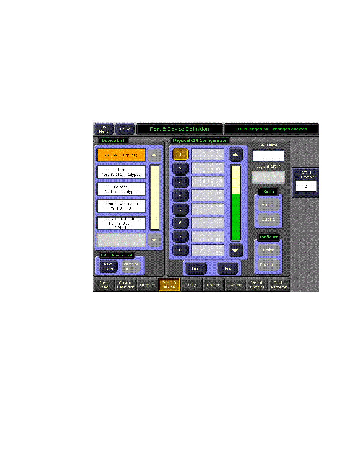
Section 3 — VTR Interface
Create a New VTR Device Definition
1. Logon to the Kalypso system as the EIC so you can change the Eng
Setup configuration (touch Daily Setups, EIC Login).
2. After logging on, go to the Eng Setup Port & Device Definition menu
(touch Eng Setup, Ports & Devices). A menu similar to Figure 55 is
displayed.
Figure 55. Port & Device Definition Menu
70 Kalypso Machine Control Interfaces Installation Instructions
Page 71

Kalypso Installation and Configuration
3. Touch New Device in the Edit Device List pane, then select VTR as the
Device Type and Encore as the Protocol (Figure 56).
Figure 56. Device Definition Data Entry Menu
4. Touch the Device Name data pad and enter the name you wish to use to
identify the device.
a. Enter VTR X (whatever name you used to identify that VTR).
CAUTION The VTR Device Name entered here must exactly match the name used by
the Encore system for that VTR.
b. Touch the Create button on the lower right. The next menu will
appear.
Kalypso Machine Control Interfaces Installation Instructions 71
Page 72

Section 3 — VTR Interface
5. Touch the Ethernet Address data pad and enter the exact value used for
the Serial Engine. Figure 57 shows the menu after the name and IP
Address have been entered. In this example the address is 192.168.0.15,
which is compatible with the default Kalypso system IP addresses.
Figure 57. Device Definition Menu with Profile Data
72 Kalypso Machine Control Interfaces Installation Instructions
Page 73

Kalypso Installation and Configuration
6. Repeat this process for every VTR controlled by that Serial Engine. A
two VTR configuration is shown in Figure 58.
Figure 58. Device Definition Menu with Four Channel Profile Configuration
Kalypso Machine Control Interfaces Installation Instructions 73
Page 74

Section 3 — VTR Interface
Assign VTR Devices to Kalypso Sources
1. Touch the Source Definition category selection button at the bottom of the
screen. Select the Engineering source on the scrolling list, name the
source with the Engineering Name data pad, select the input
number(s), and enter any keying information.
2. Touch the Device Source Type button. The Device datapad below
activates (Figure 59).
Figure 59. Source Definition Menu, Available Devices
74 Kalypso Machine Control Interfaces Installation Instructions
Page 75

Kalypso Installation and Configuration
3. Touch the Device data pad. A menu similar to Figure 60 is displayed.
Figure 60. Source Definition Menu, Available Devices
4. Touch the name button of the desired defined device. This assigns that
device for control by that selected source, and the previous menu is
displayed.
Kalypso Machine Control Interfaces Installation Instructions 75
Page 76

Section 3 — VTR Interface
5. Repeat the steps above to name each additional Kalypso source as a
VTR channel, select the input, and assign the appropriate device. These
sources are now defined as VTR channels, as shown in Figure 61.
Figure 61. Source Definition Menu, Devices Assigned
76 Kalypso Machine Control Interfaces Installation Instructions
Page 77

Kalypso Installation and Configuration
Map Each Source to a Kalypso Panel Button
1. Go to the Button Mapping menu by touching the Daily Setups button on
the Menu panel, then press User Prefs and Button Mapping buttons.
2. Assign each VTR source from the right scrolling pane to the desired
menu button on the left scrolling pane (Figure 62).
Figure 62. Button Mapping Menu, with Profile Sources Assigned
Save Kalypso Configuration Files
You should now save the Kalypso Engineering Setup file and User Prefs
files that contain the new machine control settings. This is accomplished
from the Save Load menu for Eng Setup, and the separate Save Load menu
for Daily Setups. Refer to the separate Kalypso User Manual for specific
instructions.
Note If after testing the interface, changes must be made to the Kalypso settings,
remember to save the modified Eng Setup and User Prefs configuration files.
Kalypso Machine Control Interfaces Installation Instructions 77
Page 78

Section 3 — VTR Interface
Encore Configuration
This procedure assumes the Encore
software has already been installed on
the Kalypso system. A keyboard is
required for this procedure, and a
mouse is recommended for easier OUI
navigation.
Encore Configuration
Only OUI
Software
Installed on
Kalypso?
YES
Contact OmniBus
for Information on
Configuring an
Existing System
Save
Configuration
(page 90)
(page 78)
NO
Access OUI and
Log In
(page 79)
Add Application
for VTR Control
(page 82)
Define Engine
the Application
will Use
(page 84)
Add Application
to This Engine
(page 85)
Identify VTR
(page 88)
Test
Configuration
and Operation
(page 91)
YES
All VTRs
Identified?
NO
78 Kalypso Machine Control Interfaces Installation Instructions
Page 79

Access OUI and Log In
Access OUI and Log In as SYS
1. Make sure that the Kalypso Menu panel and Serial Engine are both
connected to the network and that their IP addresses are on the same
subnet.
2. Press the Facility Manager button on the Kalypso Menu panel to go to the
Encore OUI (Figure 63).
Note Do not use the older wincui icon, if still present on your system.
Figure 63. Encore Welcome Message. KAL Login
Encore Configuration
3. Click the button on the lower right corner of the menu labeled either
Start (not logged in) or with the login name (KAL is the default shown in
Figure 63).
Kalypso Machine Control Interfaces Installation Instructions 79
Page 80

Section 3 — VTR Interface
4. If logged in as KAL the following warning message appears
(Figure 64). Select YES to logoff.
Figure 64. Logoff Warning Message
5. A popup keypad will appear next. Type SYS and press the Enter key (no
password required). Logging in as the system administrator ensures
you have full permissions for configuration changes. A Welcome
dialog will appear, with SYS identified on the lower right button
(Figure 65).
Figure 65. Encore Welcome Message, SYS Login
80 Kalypso Machine Control Interfaces Installation Instructions
Page 81
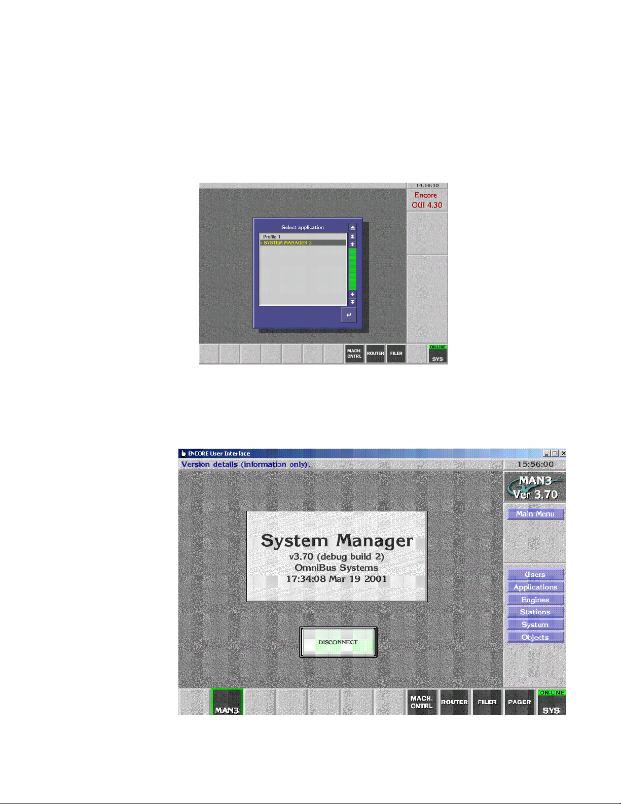
Encore Configuration
6. Close the Welcome to Encore screen by clicking on the upper right
triangle symbol Eject box on its own window (do not use the Windows
minimize or close boxes).
7. Click on an empty box on the task bar at the bottom of the screen. A
Select Application pane appears with a list of applications (Figure 66).
Figure 66.
8. Double click SYSTEM MANAGER 3 on the list. A System Manager Main
Menu window will appear (Figure 67).
Figure 67. Encore System Manager Main Menu
Kalypso Machine Control Interfaces Installation Instructions 81
Page 82

Section 3 — VTR Interface
Add Application for VTR Control
Note If a No Engines Available message appears, make sure the System Manager
application is running on the Kalypso system Windows NT desktop.
9. Click Applications on the task bar on the right side of the Main Menu. The
Application Setup window appears.
Figure 68. Encore Application Setup Menu
10. Click on Add in the lower left corner of the window. A pop up window
appears asking for the application name. An !APP_ prefix that cannot be
edited is automatically entered into the window.
11. Type in VSVC and press Enter. A pop up window will appear asking for
an application name.
12. Type in VTR Control 1 and press Enter.
13. Check the All Areas box in the middle of the screen so its green light is
illuminated.
82 Kalypso Machine Control Interfaces Installation Instructions
Page 83

Encore Configuration
14. Click on Modify to save the record to the database. The path will appear
in the File field.
Figure 69. VTR Application Data Saved
Kalypso Machine Control Interfaces Installation Instructions 83
Page 84

Section 3 — VTR Interface
Define Engine the Application will Use
15. Click on Main Menu in the right menu bar to return to the Main menu,
click on Engines in the right menu bar (Figure 70).
Figure 70. Encore Engines Menu
16. Click on Add on the lower left corner of the screen. You are prompted
for an IP address. Type the IP address of the Serial Engine you
configured earlier (the default Serial Engine IP address often used is
198.162.0.15) and then press Enter.
Note This IP address must be the same as the Serial Engine’s. You can check the
front panel display of the Serial Engine for its configured IP address.
17. A prompt will then appear asking for an engine name. Type in VTR
Control 1 (same as the application name) and press Enter.
18. For the Platform, select Device Control Engine (RISC-OS).
19. Select All Areas under Availability in the lower center part of the screen.
84 Kalypso Machine Control Interfaces Installation Instructions
Page 85

Encore Configuration
20. Click Modify to save the configuration change. The path will appear in
the window (Figure 71).
Figure 71. VTR Engine Data Saved
Add Application to This Engine
These steps tell the Encore system which application that engine can run.
21. Click the Add App. button on the lower area of the screen. A list of the
current applications will be displayed.
22. Select VTR Control 1 from the list and press Enter. It will appear in red on
the Usable Applications list.
Kalypso Machine Control Interfaces Installation Instructions 85
Page 86

Section 3 — VTR Interface
23. Click Modify to save the configuration (Figure 72).
Figure 72. Application Added to Engine
86 Kalypso Machine Control Interfaces Installation Instructions
Page 87

Encore Configuration
24. Click Main Menu on the task bar on the right, and click Disconnect
(Figure 72).
Figure 73. System Manager Disconnect
You are now finished defining the Engine and Application.
Kalypso Machine Control Interfaces Installation Instructions 87
Page 88

Section 3 — VTR Interface
Identify VTR
25. On the Encore OUI, click on any blank button at the bottom of the
menu, then double click on VTR Control 1 (Figure 74).
Figure 74. Encore VTR Machine Control
26. Click Config on the right task bar.
27. Click on Create, and type in VTR X (or whatever name you wish to use to
identify that VTR).
28. Click on Device Port, and select the port the VTR was connected to on the
Serial Engine.
29. Click Type, and select Vtr. The system automatically detects the type of
VTR and displays this information on the screen.
88 Kalypso Machine Control Interfaces Installation Instructions
Page 89
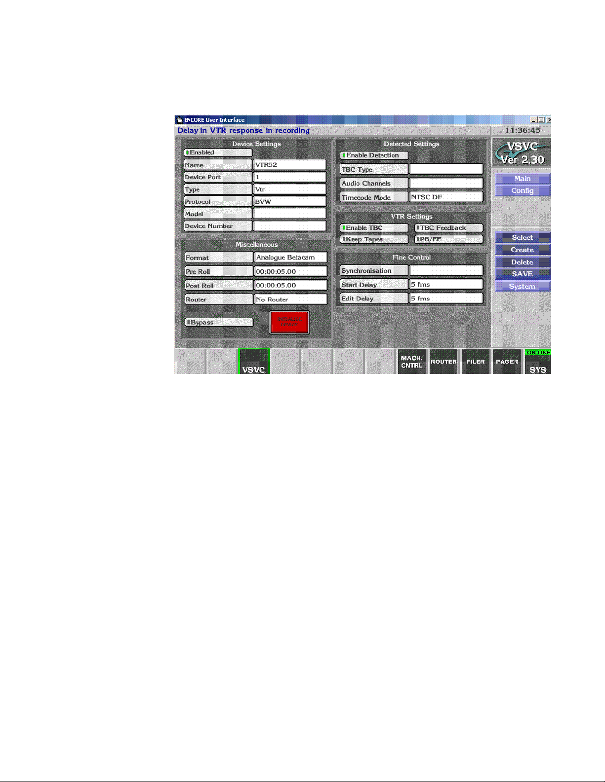
Encore Configuration
30. Make sure Enabled is on in the upper left corner (Figure 75).
Figure 75. VTR Identified
31. Repeat steps Step 27 through Step 30 for each VTR connected to the
Serial Engine ports.
Kalypso Machine Control Interfaces Installation Instructions 89
Page 90
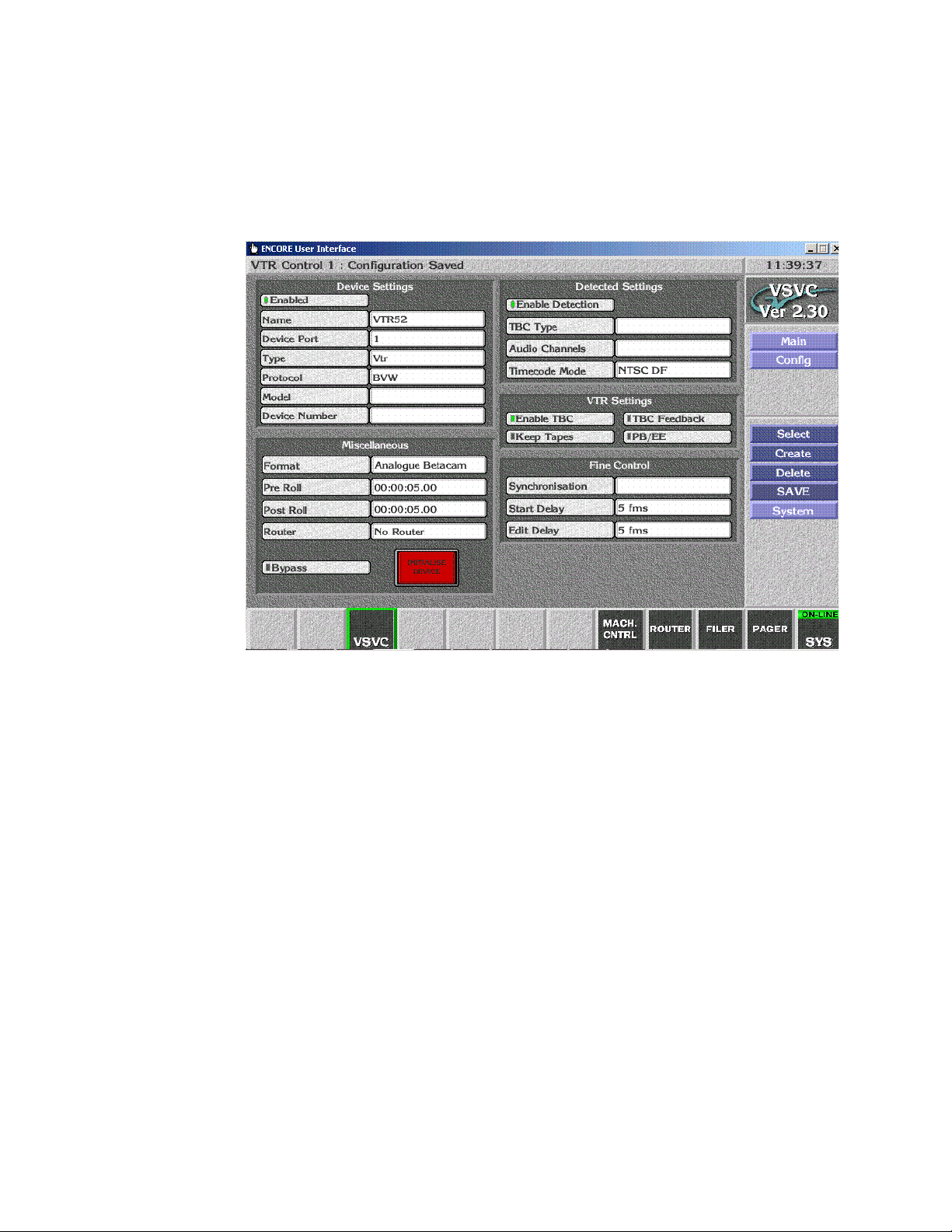
Section 3 — VTR Interface
Save Configuration
32. Save the config by clicking on SAVE in the right task bar. A
Configuration Saved message will appear (Figure 76).
Figure 76. VTR Configuration Saved
33. Click Main on the task bar on the right, and click Disconnect.
This completes the Encore database configuration. You should now test
VTR operation using the Encore OUI.
90 Kalypso Machine Control Interfaces Installation Instructions
Page 91
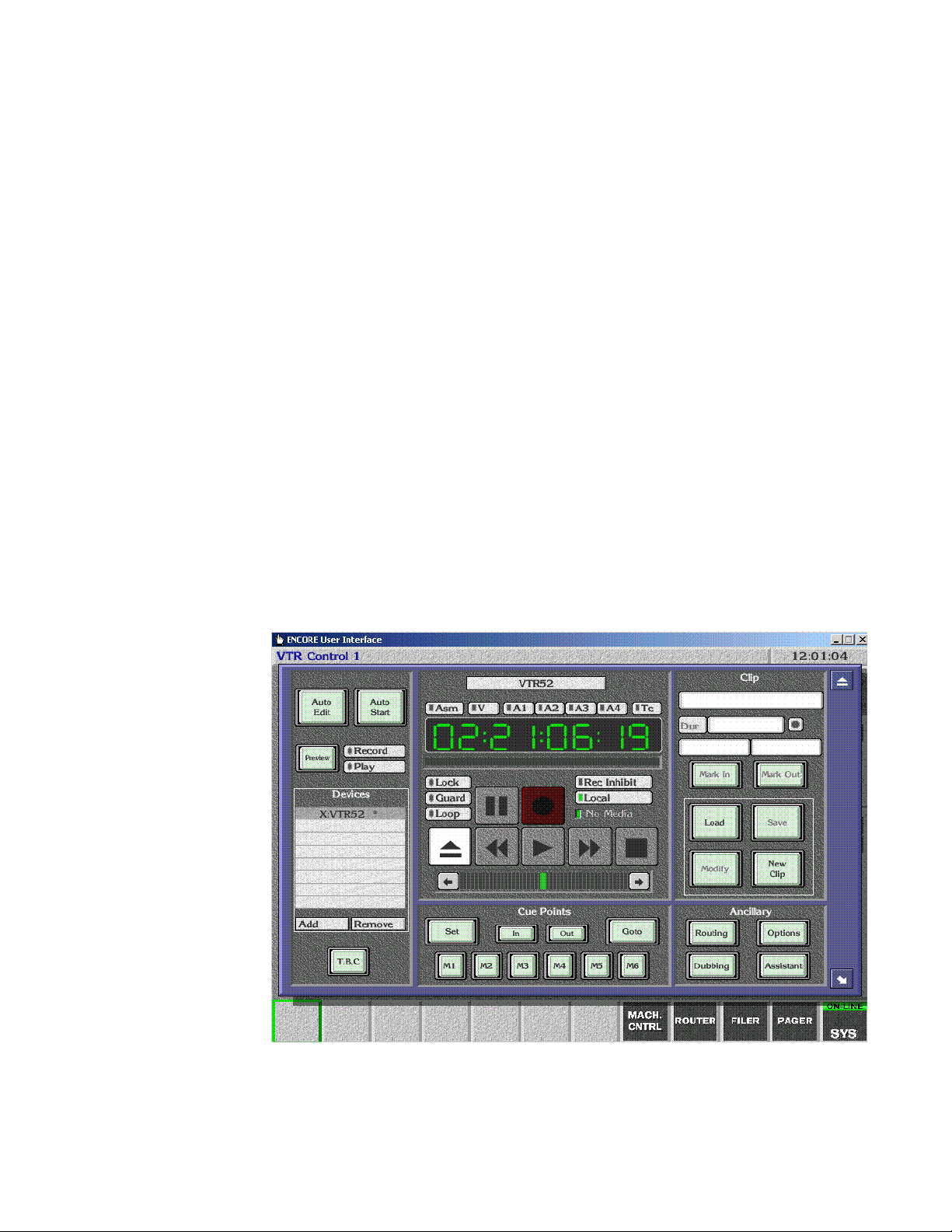
Test Configuration and Operation
With VSVC installed and the Kalypso and Encore systems configured, you
should have machine control from the Kalypso Main panel. Source buttons
mapped to devices should no longer have a ? status indicator.
If control is not working properly, you can use the following procedures to
test whether the problem resides on the Encore system or the Kalypso
system.
Test VTR OUI Operation
1. Click on the Local MACH. CNTRL button at the bottom of the screen.
2. Press the Add button on the lower left to display a list of devices.
3. Select a VTR on the list and press Enter.
4. Load a video tape into the selected VTR, making sure it is in remote
operation mode.
Test Configuration and Operation
5. Press the Play, Stop, and Rewind buttons on the OUI. Timecode values
on the screen should be updated as the tape moves (Figure 77).
Figure 77. Encore Local Machine Control
This test proves that a VTR is under Encore control. You can now test
control of the VTR from the Kalypso Main panel.
Kalypso Machine Control Interfaces Installation Instructions 91
Page 92

Section 3 — VTR Interface
Test Kalypso VTR Interface Operation
Test that the VTR can be controlled directly with the Kalypso system.
• Select a VTR to control on the PGM PST B bus (or whatever bus has
been delegated),
• Load a VTR into that machine
• Make sure the VTR is in remote operation mode, and
• Play, Stop, Fast Forward, and Rewind the tape using the Kalypso
Machine Control subpanel.
You have now completed the VTR interface installation and configuration
for Kalypso control.
Note You should now back up the Encore configuration files (see Saving Encore
Machine Control Configurations on page 25).
92 Kalypso Machine Control Interfaces Installation Instructions
Page 93

Section 4
Using the Encore Operational User Interface (OUI)
Introduction
Kalypso system operators can use the Encore OUI to control external
devices independent of the Kalypso Machine Control subpanel. This can be
used for troubleshooting (as described earlier in the Profile installation section), or a an additional control mechanism. After installation and configuration, touching Facility Manager on the Kalypso Home menu brings up the
Encore OUI.
To get the most out of this section, you should:
• Have a basic understanding of media clips,
• Know how files are organized and maintained on the Encore network,
and
• Know how to use any remote applications you select.
This section describes how to:
• Use the Encore Operational User Interface (OUI) and local applications,
• Use the Local Machine Control Panel to work with clips on networked
devices,
• Use the Filer-Fax to manage files, and
• Use the OmniPager to send short messages around the network.
Note The exact capabilities of your Encore system may vary. Refer to the separate
Encore Control System documentation for information about features not
covered in this section.
Kalypso Machine Control Interfaces Installation Instructions 93
Page 94
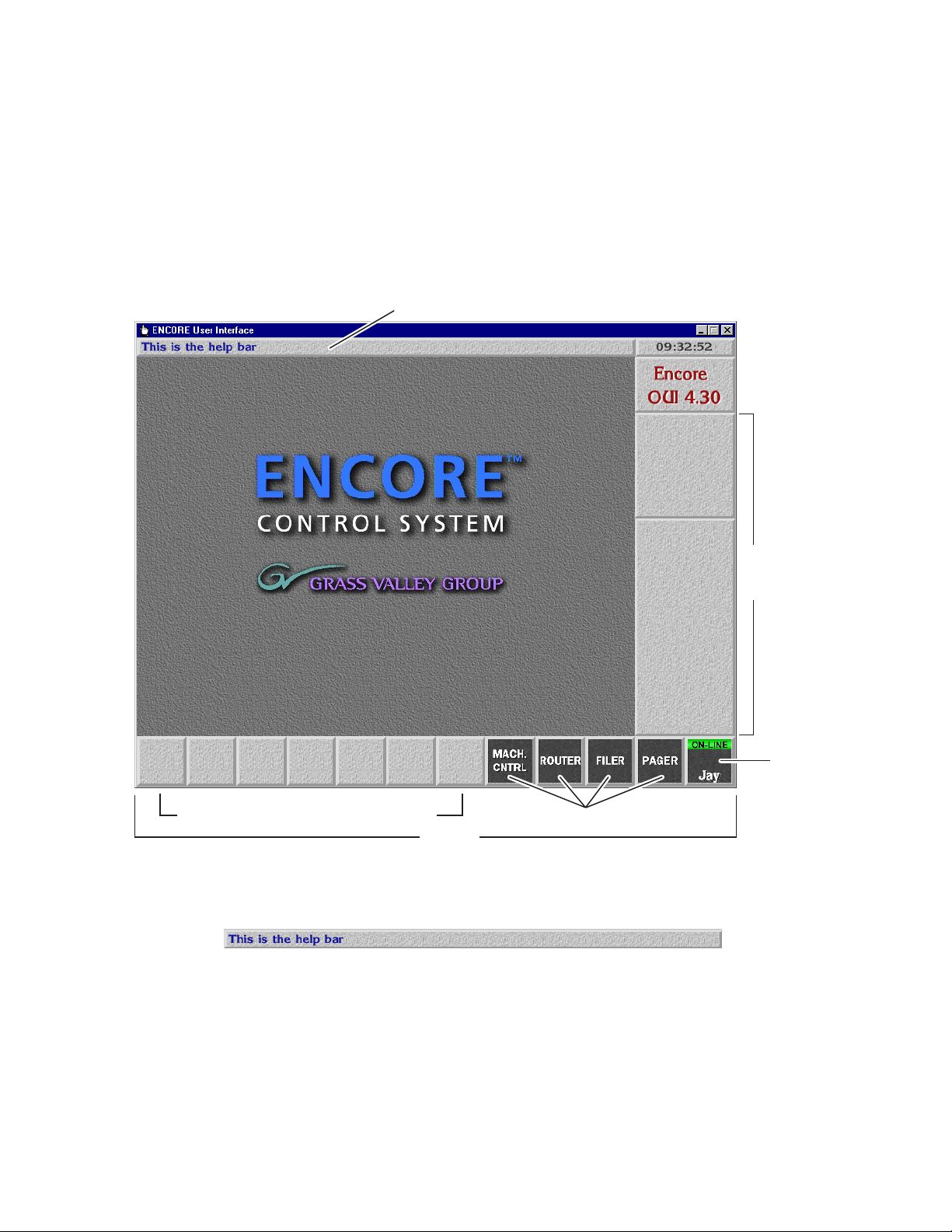
Section 4 — Using the Encore Operational User Interface (OUI)
Common Display Features
Encore Desktop
When you logon to the system, the Encore Desktop appears (Figure 78).
Figure 78. The Encore Desktop
Help Bar
Tiles Where Remote Application Icons Appear
Help Bar — As you move the mouse pointer around the
screen, the Help Bar displays information on the areas it
passes over.
Menu Bar
Start-up /
Shut Down
Icon
Local OUI Application Icons
Task Bar
94 Kalypso Machine Control Interfaces Installation Instructions
Page 95

Common Display Features
Clock — Click the Clock in the top right corner of the
Desktop to show or hide the Menu Bar. The Menu Bar
appears to the right on the Desktop.
Title Box — The Title Box displays the name of the currently
active application. Click the Title Box to view the status
information your workstation.
Task Bar — When an application is open, its icon shows on
the Task Bar. To load an application, click its icon. You can
switch between applications by clicking different icons.
Menu Bar — The Menu Bar has an upper and a lower section.
The lowest button in the upper section acts as a heading for
the lower section. The buttons on the Menu Bar may be different, depending on the application you’re viewing/using
at the moment.
There may be two types of buttons on the Menu Bar:
• Light-blue buttons represent categories; click one to
display a further level of options.
• Dark-blue buttons control a specific action.
The Menu Bar contents change depending on the category you select from the Main Menu.
Kalypso Machine Control Interfaces Installation Instructions 95
Page 96

Section 4 — Using the Encore Operational User Interface (OUI)
Buttons
Indicator Button — An indicator button has an indicator
which changes color when you click the button. The indicator may be a small rectangle or the whole button.
Greyed-out Button — You cannot select greyed-out buttons.
Active Button — You can select a button that is not greyed out.
Icons and Windows
Re-Size Icon — Use the Re-size icon to alter the size of a
window. The icon is in the bottom right corner of the
window.
To re-size a window, click the icon and drag the mouse
while holding the mouse button down.
To move a window without affecting the size, click-hold on
the window edge and drag the mouse.
Enter/Return Icon — Click this icon to confirm information
you enter. You can also use the Enter/Return key on your keyboard for this purpose.
Eject Icon — Click this icon to close a window. This icon is
located in the top right corner of windows. You can also
use your keyboard Esc key for the same purpose.
96 Kalypso Machine Control Interfaces Installation Instructions
Page 97

Common Display Features
Alphanumeric Keypad — You can use the Alpha-
numeric Keypad to enter text and numbers.
Click the keys on the Keypad or use the keyboard of your workstation.
List Window — A List window contains a list of items which
you can search, view or select.
Click the Single Arrow icons ( ) to scroll up and
down the list by one line at a time
Click the Double Arrow icons ( ) to scroll up and
down the list by one page at a time
Click and move the green slider bar ( ) to scroll through
a list window.
If you press a character on your workstation keyboard, the
list scrolls until the first item that starts with that character
appears at the top. For example, press M to move to the
first item beginning with the letter M.
You can also use the arrow keys and the Page Up/ Page Down
keys on the keyboard to search.
Kalypso Machine Control Interfaces Installation Instructions 97
Page 98

Section 4 — Using the Encore Operational User Interface (OUI)
Numeric Keypad — Use the Numeric Keypad to enter time
codes.
To enter time codes in frames, click the Frames button.
To enter time codes in hours, minutes, seconds and frames,
click the Tcode button.
Click the double arrow icons ( ) to the left of the
window to increase or decrease the time code in onesecond steps.
Click the single arrow icons ( ) to the right of the
window to increase or decrease the time code by one frame
at a time.
Clicking the decimal point ( ) causes a colon (:) to appear
in the timecode display so that:
15 enters as 00:00:00:15 (15 frames)
15. enters as 00:00:15:00 (15 seconds)
15. enters as 00:15:00:00 (15 minutes)
To enter a Keypad number or function, click a key on the
Numeric Keypad graphic, or use your keyboard.
Use the keys to perform simple calculations.
Copy To Clip Pad — Use the Copy To Clip Pad icon to copy text or
numbers to the Clip Pad list window.
Retrieve From Clip Pad — Use the Retrieve From Clip Pad icon to
select the Clip Pad so that you can retrieve information.
98 Kalypso Machine Control Interfaces Installation Instructions
Page 99
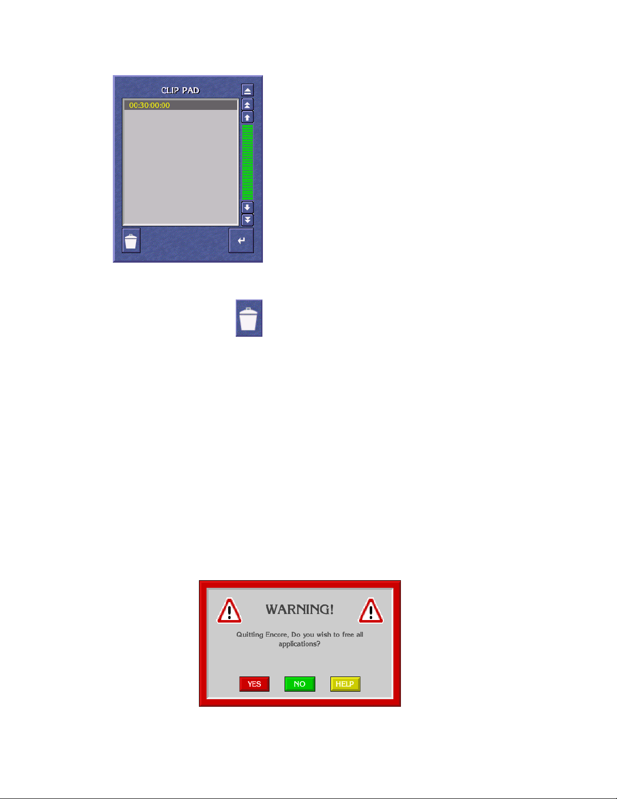
Common Display Features
Clip Pad — Use the Clip Pad to store useful information. To
retrieve a Clip Pad item, highlight it in the list window,
then click the Enter/Return icon.
Dustbin Icon — To remove an entry from the Clip Pad, high-
light the item and click the Dustbin Icon.
Messages
Message Window (with options)
A Message Window may appear when you are using an Encore application. The message may ask you to confirm an action by clicking one of the
buttons in the Window.
To continue, click a button; or, using your keyboard, press the first letter of
the button name (for example, press the Y key instead of clicking the Yes
button).
Figure 79. Message Window With Options
Kalypso Machine Control Interfaces Installation Instructions 99
Page 100
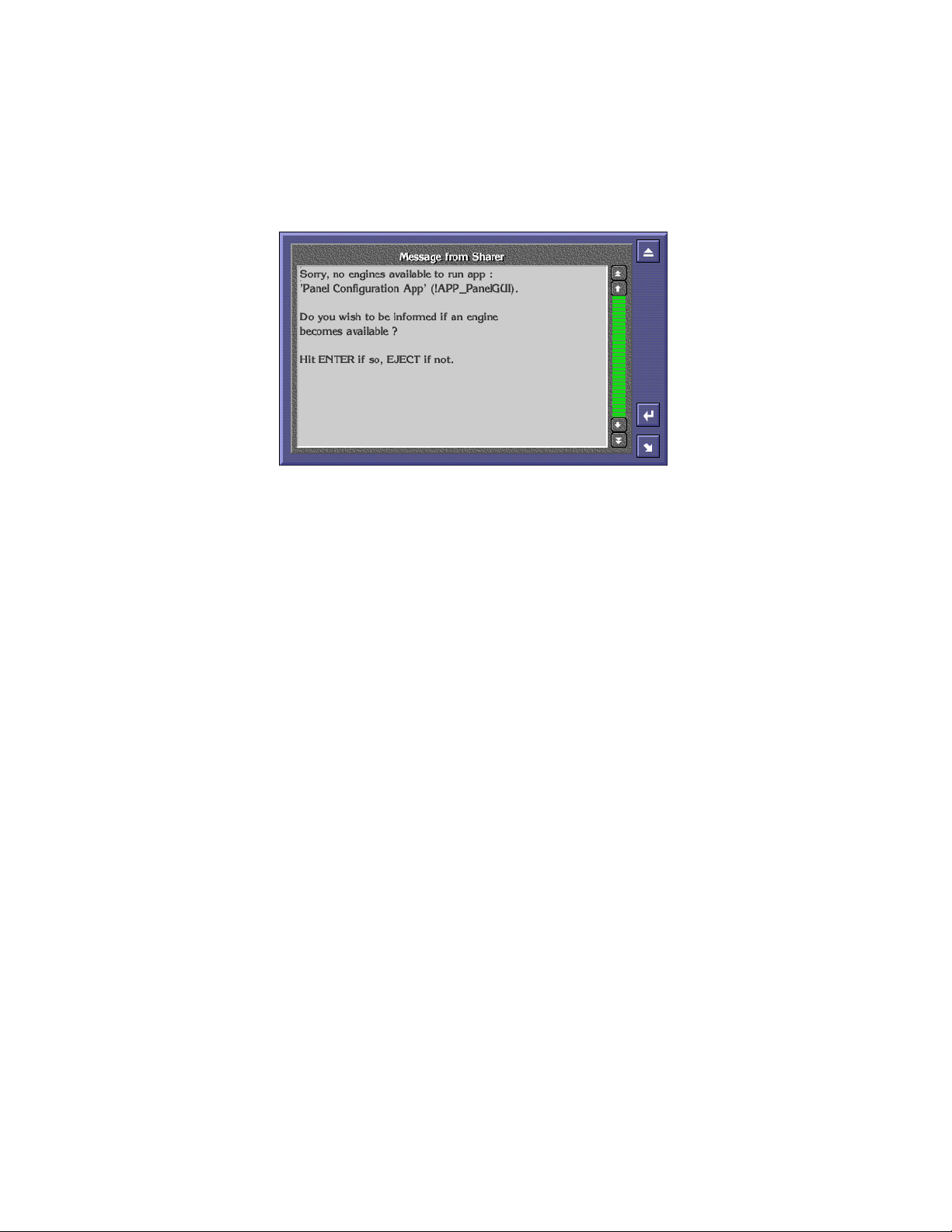
Section 4 — Using the Encore Operational User Interface (OUI)
Message Window (without options)
If there are no options, click the window or press the Enter/Return key on
your keyboard.
Figure 80. Message Window Without Options
Selecting options
Procedures
Logging onto the OUI
You can usually select options in two ways:
• Double click the required option, or
• Click once to highlight the option, and then press the Enter/Return key on
your keyboard.
This section describes how to:
• Logon to the OUI,
• Load an application,
• Request an application from another user, and
• Log off the OUI.
When you switch on your OUI workstation, the system displays the OUI
Logon Screen. From this screen you can logon to your OUI workstation
and load the applications you want to use.
1. Click the Start button on the right of the task bar. The Logging-On User
Identity Box appears.
100 Kalypso Machine Control Interfaces Installation Instructions
 Loading...