

Page 1
KMV-3901/3911
SPACE SAVING, SINGLE AND DUAL QUAD-SPLIT MULTIVIEWER
Quick Start Guide
M866-9905-111
2015-06-01
Page 2

Notices
Copyright & Trademark Notice
Copyright © 2010–2015, Grass Valley USA, LLC. All rights reserved.
Belden, Belden Sending All The Right Signals, and the Belden logo are trademarks or
registered trademarks of Belden Inc. or its affiliated companies in the United States and
other jurisdictions. Grass Valley, KMV-3911, KMV-3901, Kaleido-X, iControl, and Densité are
trademarks or registered trademarks of Grass Valley USA, LLC. Belden Inc., Grass Valley USA,
LLC, and other parties may also have trademark rights in other terms used herein.
Terms and Conditions
Please read the following terms and conditions carefully. By using Kaleido multiviewer
documentation, you agree to the following terms and conditions.
Grass Valley hereby grants permission and license to owners of Kaleido multiviewers to use
their product manuals for their own internal business use. Manuals for Grass Valley
products may not be reproduced or transmitted in any form or by any means, electronic or
mechanical, including photocopying and recording, for any purpose unless specifically
authorized in writing by Grass Valley.
A Grass Valley manual may have been revised to reflect changes made to the product
during its manufacturing life. Thus, different versions of a manual may exist for any given
product. Care should be taken to ensure that one obtains the proper manual version for a
specific product serial number.
Information in this document is subject to change without notice and does not represent a
commitment on the part of Grass Valley.
Warranty information is available from the Legal Terms and Conditions section of Grass
Valley’s website (www.grassvalley.com).
The SDHC Logo is a trademark of SD-3C, LLC.
Title KMV-3901/3911 Quick Start Guide
Part Number M866-9905-111
Revision 1 June 2015, 5:27 pm
ii
Page 3
Electrostatic Discharge (ESD) Protection
Electrostatic discharge occurs when electronic components are improperly
handled and can result in intermittent failure or complete damage adversely
affecting an electrical circuit. When you remove and replace any card from a frame
always follow ESD-prevention procedures:
• Ensure that the frame is electrically connected to earth ground through the power cord
or any other means if available.
• Wear an ESD wrist strap ensuring that it makes good skin contact. Connect the
grounding clip to an unpainted surface of the chassis frame to safely ground unwanted
ESD voltages. If no wrist strap is available, ground yourself by touching the unpainted
metal part of the chassis.
• For safety, periodically check the resistance value of the antistatic strap, which should
be between
• When temporarily storing a card make sure it is placed in an ESD bag.
• Cards in an earth grounded metal frame or casing do not require any special ESD
protection.
1 and 10 megohms.
KMV-3901/3911
Quick Start Guide
Protection contre les décharges électrostatiques (DES)
Une décharge électrostatique peut se produire lorsque des composants
électroniques ne sont pas manipulés de manière adéquate, ce qui peut entraîner
des défaillances intermittentes ou endommager irrémédiablement un circuit
électrique. Au moment de remplacer une carte dans un châssis, prenez toujours les
mesures de protection antistatique appropriées
• Assurez-vous que le châssis est relié électriquement à la terre par le cordon
d'alimentation ou tout autre moyen disponible.
• Portez un bracelet antistatique et assurez-vous qu'il est bien en contact avec la peau.
Connectez la pince de masse à une surface non peinte du châssis pour détourner à la
terre toute tension électrostatique indésirable. En l’absence de bracelet antistatique,
déchargez l’électricité statique de votre corps en touchant une surface métallique non
peinte du châssis.
• Pour plus de sécurité, vérifiez périodiquement la valeur de résistance du bracelet
antistatique. Elle doit se situer entre 1 et 10
• Si vous devez mettre une carte de côté, assurez-vous de la ranger dans un sac
protecteur antistatique.
• Les cartes qui sont reliées à un châssis ou boîtier métallique mis à la terre ne
nécessitent pas de protection antistatique spéciale.
:
mégohms.
Recycling
Visit www.grassvalley.com for recycling information.
iii
Page 4
Notices
Certification and Compliance
Electromagnetic Compatibility
This equipment has been tested for verification of compliance with FCC Part 15,
Subpart B requirements for class A digital devices.
Note: This equipment has been tested and found to comply with the
limits for a Class A digital device, pursuant to part 15 of the FCC Rules.
These limits are designed to provide reasonable protection against
harmful interference when the equipment is operated in a commercial
environment. This equipment generates, uses, and can radiate radio
frequency energy and, if not installed and used in accordance with the
instruction manual, may cause harmful interference to radio
communications. Operation of this equipment in a residential area is
likely to cause harmful interference in which case the user will be
required to correct the interference at his own expense.
This equipment has been tested and found to comply with the requirements of the
EMC directive 2004/108/EC:
• EN 55022 Class A radiated and conducted emissions
• EN 61000-3-2 Limits for harmonic current emissions
• EN 61000-3-3 Limitation of voltage changes, voltage fluctuations and flicker
• EN 61000-4-2 Electrostatic discharge immunity
• EN 61000-4-3 Radiated, radio-frequency, electromagnetic field immunity
• EN 61000-4-4 Electrical fast transient/burst immunity
• EN 61000-4-5 Surge transient immunity
• EN 61000-4-6 Conducted disturbances immunity
• EN 61000-4-8 Power frequency magnetic field immunity
• EN 61000-4-11 Voltage dips, short interruptions and voltage variations
immunity
Environmental Compliance
部件名称 Part name
电缆及电缆组件 Cables and cable assemblies
电路模块 Circuit modules
组装风扇 Fan assemblies
O: 表示该有毒有害物质在该部件所有均质材料中的含量均在 SJ/T 11363-2006 规定的
限量要求以下。
iv
有毒有害物质或元素 (Toxic or hazardous substances and elements)
铅
(Pb)
汞
(Hg)
X O O O O O
X O O O O O
X O O O O O
镉
(Cd)
六价铬
(Cr6)
多溴联苯
(PBB)
多溴二苯
(PBDE)
Page 5

KMV-3901/3911
Quick Start Guide
O: Indicates that this toxic or hazardous substance contained in all of the homogeneous
materials for this part is below the limit requirement in SJ/T11363-2006.
X: 表示该有毒有害物质至少在该部件的某一均质材料中的含量超出 SJ/T 11363-2006
规定的限量要求。
X: Indicates that this toxic or hazardous substance contained in at least one of the
homogeneous materials for this part is above the limit requirement in SJ/T11363-2006.
技术条款解释:此声明所依据之数据由 Grass Valley 环境管理部门向我们的部件供
应商获取。Grass Valley 公司相信此信息的正确性,但由于数据来源于公司外部,我
们无法保证它的完整和准确。所有这些特性可能在未获通知的情况下更改。
Technical explanations: This statement is based on the information provided by our
suppliers of components and collected through our Grass Valley’s environmental
management system. Grass Valley believes this environmental information to be correct
but cannot guarantee its completeness or accuracy as it is based on data received from
sources outside our company. All specifications are subject to change without notice.
v
Page 6

Page 7

Welcome to the Kaleido family of multiviewers! This Quick Start Guide is designed to help
you get your Kaleido-Modular KMV-3901/3911 multiviewer up and running for the first
time. The following sections will guide you through the installation of a KMV-3901/3911
system in its default configuration.
Summary
Introduction . . . . . . . . . . . . . . . . . . . . . . . . . . . . . . . . . . . . . . . . . . . . . . . . . . . . . . . . . . . . . . . . . . . . . . . . . . 1
Getting Organized . . . . . . . . . . . . . . . . . . . . . . . . . . . . . . . . . . . . . . . . . . . . . . . . . . . . . . . . . . . . . . . . . . . . 2
Step 1: Physical Setup . . . . . . . . . . . . . . . . . . . . . . . . . . . . . . . . . . . . . . . . . . . . . . . . . . . . . . . . . . . . . . . . . 4
Step 2: Networking Setup . . . . . . . . . . . . . . . . . . . . . . . . . . . . . . . . . . . . . . . . . . . . . . . . . . . . . . . . . . . . . . 8
Step 3: XEdit Installation . . . . . . . . . . . . . . . . . . . . . . . . . . . . . . . . . . . . . . . . . . . . . . . . . . . . . . . . . . . . . . 18
Introduction
Grass Valley's Kaleido family of multiviewers ranges from quad-splits to large-scale, multiroom monitoring systems, with outstanding image quality and signal flexibility. The
Kaleido multiviewers are available in different models: the Kaleido-MX, the Kaleido-MX
the Kaleido-IP, the Kaleido-X (7RU), the Kaleido-X (4RU), the Kaleido-X16, and the
Kaleido-XQUAD frames, as well as the Kaleido-Modular-X cards, and the Kaleido-Modular
KMV-3901/3911 cards.
Setting Up Your KMV-3901/3911
Multiviewer
4K,
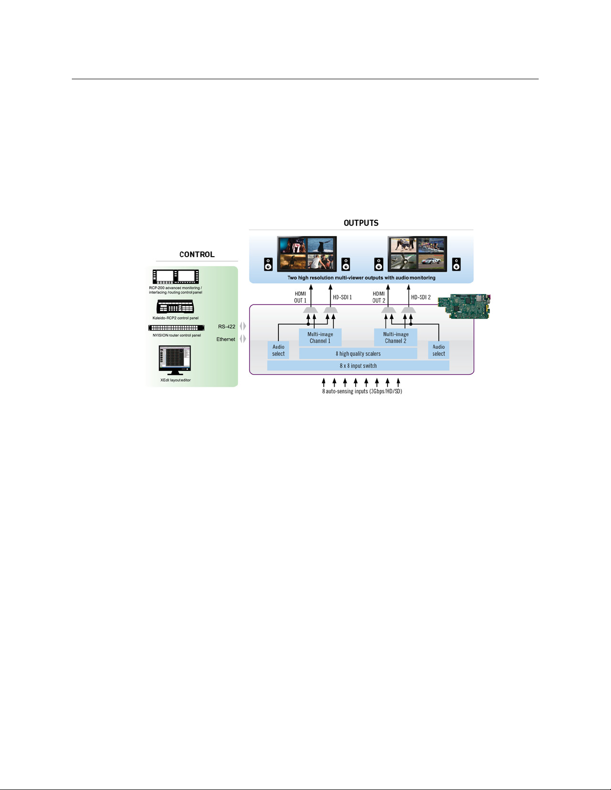
The Kaleido-Modular KMV-3911 and KMV-3901 cards can display up to eight 3Gbps, HD,
or SD inputs in up to eight video windows across one or two high-resolution outputs. By
using optional cascading bridges, up to three KMV-3901/3911 cards can be configured into
a single- or dual-output system supporting up to 24
At the heart of every multiviewer system is the Kaleido-X software, which includes the
following client applications:
• XAdmin is a Web client that your system administrator will use to manage the
multiviewer system.
• XEdit is a client application used to create layouts for the monitor wall, and to configure
the multiviewer, from your PC or laptop.
•The Router Control Software Single Bus and Matrix View applications (also part of the
iRouter Router Control Software packaged with iControl Application Servers) can be
used to control your multiviewer’s logical sources and monitor wall destinations, via
the KX Router logical router, or to control other logical routers configured within your
multiviewer system.
• Signal Path Viewer opens as a standalone panel, updated in real time, showing
assignment information between router sources and multiviewer inputs. Signal Path
Viewer is available for all multiviewer models, except Kaleido-IP (for which it is not
relevant).
inputs.
1
Page 8
Setting Up Your KMV-3901/3911 Multiviewer
Getting Organized
A Kaleido-Modular KMV-3901/3911 multiviewer system in its default configuration includes a number of
layout presets. The default output head configuration is set to automatically detect the resolution of the
associated display. If this information is not available, it will fall back to 1920 × 1080 @ 60 Hz (HDTV). The
Kaleido-Modular range offers the most space- and energy-efficient multiviewer system. Housed in a
3+ FR1, Densité 3 or Densité 3 mini frame, the expandable, eight-input, dual-output KMV-3911 card
Densité
replaces the earlier KMV-3901 model in the Kaleido-Modular range. A single 3
up to 10 KMV-3911 (or KMV-3901) multiviewer cards, providing up to 20 quad-split outputs. The highly
compact, half-1 RU Densité 3 mini frame can hold a single multiviewer card, providing up to two quad-split
outputs. The Densité
The Kaleido-Modular range is ideal for production monitoring in trucks. It integrates tightly with other
Densité signal processing cards, routers and production switchers.
3+ FR1 frame can hold two multiviewer cards, providing up to four quad-split outputs.
RU Densité 3 frame can hold
Overview of single card functionality
Kaleido-Modular KMV-3901/3911 systems are available in the following sizes: 4 × 1, 4 × 2,
× 1, 8 × 2, 12 × 1, 12 × 2, 16 × 1, 16 × 2, 20 × 1, 20 × 2, 24 × 1 and 24 × 2. In addition to the
8
earlier model’s features, the KMV-3911 supports up to two HD-SDI monitoring outputs.
Getting Organized
This section provides information about system requirements, and items shipped with your
KMV-3901/3911 card.
Required Materials
Your KMV-3901/3911 system package includes the following:
• KMV-3911 (or KMV-3901) card (front and rear modules)
• One or two 35-cm (14-inch) DIN-to-BNC cable adapters (for KMV-3911 models with HDSDI monitoring output option only)
• The KMV-3901/3911 Quick Start Guide (this document)
2
Page 9
KMV-3901/3911
Quick Start Guide
• DVD including the Release Notes for the current version of the Kaleido-X software, the
Kaleido-X User’s Manual, database samples, Quick Start guides and hardware reference
manuals for all multiviewer models
Note: In line with our commitment to environmental preservation, only the
Quick Start Guide for your multiviewer model, and some ancillary
documents (e.g. welcome letters, warranty cards) are distributed in printed
form. All manuals are available on the DVD that shipped with your
multiviewer. See the “Documentation” section of the Release Notes for a
complete list. You can obtain the latest version of the manuals, the Release
Notes, as well as software and useful data, from the Documentation Library
section of Grass Valley’s website.
In addition to the above, you will need the following (not supplied):
•Up to 2 displays
• A dedicated 100Base-T Ethernet switch with enough ports for the KMV-3901/3911,
client PCs, and Kaleido-RCP2 units
• Client PC (see below for system requirements)
• Cables (to connect your multiviewer to video sources, to displays, and to the network):
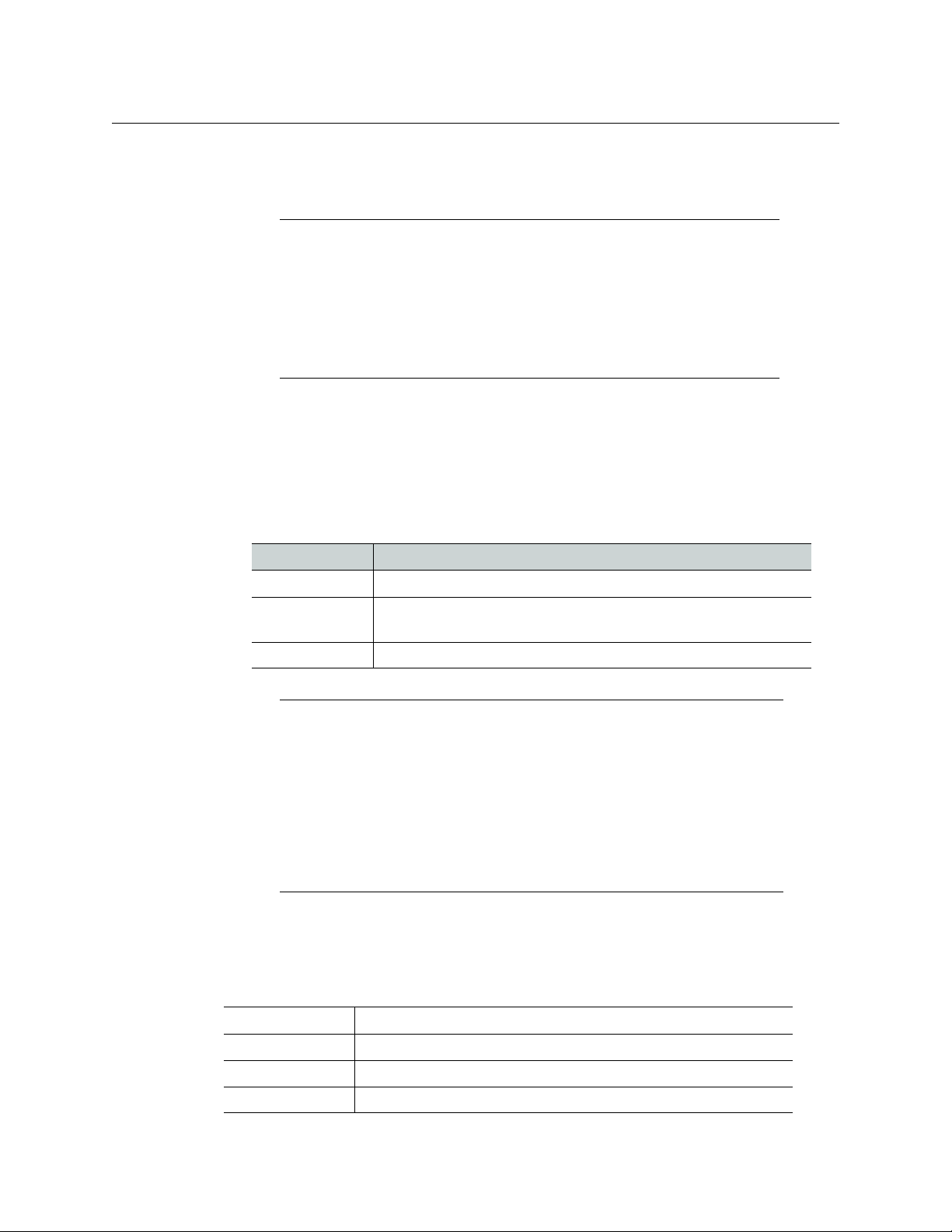
Cable type Purpose
CAT-5 For Ethernet connectivity
Display cables Either extension modules—for example Grass Valley’s DXF-200
(part number DXF-200-C)—or standard HDMI cables (non-locking)
Video cables Standard coaxial cables with BNC connectors
Notes
• On all Kaleido multiviewers, the network adapters are set to autonegotiate. By default, the connection speed and duplex mode will be set
automatically based on the corresponding port settings on the switch.
• If you have two displays, make sure the HDMI connectors on the
multiviewer side have the same dimensions. Otherwise, the multiviewer’s
built-in locking mechanism will not be able to secure the smaller of the
two connectors. You may order suitable HDMI cables from Grass Valley—
HDMI to DVI female cable (1ft), part no. KXC-HDMI-DVI.
System Requirements for a Client PC
A client PC or laptop meeting the following requirements is required to access the XAdmin
Web client, and the other Kaleido-X client applications.
Operating system Windows XP Professional, Windows 7, Windows 8, or Windows 8.1
Processor Core 2 Duo at 2 GHz, or better
Memory At least 2 GB of RAM
Disk space At least 2 GB free
3
Page 10

Setting Up Your KMV-3901/3911 Multiviewer
Select button
Status LED
Boot LED,
Power LED,
CPU Status LED (other side of board)
SDI LEDs
USB connector (other side of board)
Physical Setup
Step 1: Physical Setup
IMPORTANT
Make sure the KMV-3901/3911 cards are NOT connected to the network
To avoid IP-address conflicts during this initial physical setup make sure none
of the multiviewer cards are connected to the network—i.e. make sure there
is no cable connected to your cards’ ETH port—before powering up the
Densité frame.
Densité CPU-ETH2 Enhanced Ethernet Controller Card
A Densité frame housing a KMV-3901/3911 multiviewer card must have a
controller card (Densité CPU-ETH2 Enhanced Ethernet Controller Card) with
firmware version 2.0.4 or later. A controller with an earlier version of the
firmware cannot provide a time reference to the multiviewer card. Make sure
the controller’s internal clock is set to the correct date and time. The clock
settings will persist for 10 days after a power loss. Should you need to change
the time on a Densité CPU-ETH2 controller, then make sure to restart all
multiviewers located in the same housing frame as the controller card. Refer
to the Densité CPU-ETH2 Enhanced Ethernet Controller Card Guide to
Installation and Operation for more information.
To set up the multiviewer hardware
1 Referring to the Guide to Installation and Operation that shipped with your
Densité
3+ FR1, Densité 3 mini or Densité 3 housing frame, mount the KMV-3901/3911
multiviewer card and associated rear panel in the housing frame, and then power up
the frame.
Leave the frame door open so that you can monitor all the card’s LEDs.
Note: For more information on the card’s LEDs, refer to the KMV-3901/3911
Guide to Installation and Operation, available on the DVD that shipped with
your system.
The KMV-3901/3911 card starts up. The startup sequence takes approximately five
minutes, during which time the Status LED is blinking orange:
4
Page 11

KMV-3901/3911
Quick Start Guide
Once the startup has completed, the Status LED should be red (steady) because the
card is not connected to the network yet:
Green Blinking orange Red Blinking red
Normal Booting (or the card is
selected for local control)
No Ethernet / SD card
error
Fan failure / no rear /
duplicate IP address
2 Connect a client PC, and the Kaleido-RCP2 (if available) to a dedicated 100Base-T
Ethernet switch (see
Cabling Diagram, on page 8). You can also connect a mouse and a
keyboard to your Kaleido-RCP2.
Notes
• The Kaleido-RCP2 is an optional device, and may not have been shipped
with your KMV-3901/3911 system. For information on this and other
options for your multiviewer system, please contact your Grass Valley sales
representative.
• You may need to upgrade your Kaleido-RCP2 devices (if available) to the
latest firmware. The update file can be found on the DVD that shipped with
your multiviewer, and on Grass Valley’s website. Please refer to the Kaleido-
RCP2 Guide to Installation and Operation (available on the DVD, and from
the Documentation Library section of Grass Valley’s website) for
instructions on how to determine the firmware level, and how to perform
the upgrade.
The KMV-3901/3911 multiviewer has been configured to automatically detect the
resolution of any connected display. If the required information is not available, then a
fall-back resolution of 1920
× 1080 @ 60 Hz (HDTV) is used.
3 Connect at least one output of the multiviewer to a display that supports this
resolution (see
Cabling Diagram, on page 8).
• Monitor wall displays: Connect the multiviewer’s MV OUT outputs to the displays.
• Broadcast monitors: If your installation involves broadcast monitors, connect
1
them to the appropriate SDI outputs.
It is also possible to connect SDI outputs to a
router. Refer to Configuring the HD-SDI Monitoring Output Format, in the Kaleido-X
User’s Manual, for instructions on setting the scan format.
If you wish to use a different resolution, see Changing the Output Resolution, below, for
detailed instructions.
Note: If your display is not collocated with your Densité frame you may
choose to employ a DXF-200 transmitter/receiver device that allows you to
install a display up to 1,000 meters (3,300 feet) from the signal source. For
more information on the DXF-200, refer to the DXF-200 DVI/HDMI Optical
Extension System User’s Manual (part no. M916-9900-104).
4 Connect one or more video sources to your multiviewer’s inputs (see Cabling Diagram,
on page 8).
1.Available on KMV-3911 only.
5
Page 12

Setting Up Your KMV-3901/3911 Multiviewer
Select button
Status LED
SDI LEDs
2
1
3
4
5
6
7
8
Select button
Status LED
Boot LED,
Power LED,
CPU Status LED (other side of board)
SDI LEDs
USB connector (other side of board)
Physical Setup
5 Check that all SDI LEDs associated with the connected video inputs are green:
Changing the Output Resolution
IMPORTANT
All KMV-3901/3911 cards within a housing frame must have their output
heads configured with the same refresh rate. If your frame is referenced, then
the heads’ refresh rate must also match the reference signal's refresh rate.
To change a display’s resolution from the Densité controller’s local control panel
1 Press the Select button on the front edge of the KMV-3901/3911 card.
6
Page 13

KMV-3901/3911
Quick Start Guide
The Status LED on the selected card flashes orange, and the associated control menu
appears on the LCD display of the Densité frame’s local control panel.
Note: You can navigate the control menu by using the four buttons located
beneath the display:
• Press the [+] and [–] buttons, to navigate between menu options or
between parameter values.
• Press SEL to access the next menu level. When a parameter value is shown
on the display, modify the value by using the [+] and [–] buttons, and then
press SEL to apply the new value.
• Press ESC to go back to the previous menu level.
• Once you have completed your changes, press the Select button on the
front edge of the KMV-3901/3911 card to exit the control menu.
2 On the local control panel, press the [–] button twice, until RESOLUTION appears on the
LCD display:
3 Press the SEL button.
HEAD 1 appears on the control panel’s LCD display.
4 Press the SEL button again.
5 The current resolution for the display that is connected to the multiviewer’s output
head 1 (i.e. through the MV OUT 1 connector) appears on the LCD display.
6 Press the [+] and [–] buttons, to navigate to a suitable output resolution for your
display.
7 Press SEL to apply the value shown on the display.
The selected resolution is applied to the display.
8 Press ESC to return to the previous level in the local control menu.
HEAD 1 appears again on the LCD display.
9 If you wish to change the resolution on the second display (if available), then press the
[–] button.
HEAD 2 appears on the LCD display and you can repeat step 4 to step 8 above to verify
or configure the resolution of the display that is connected to the multiviewer’s output
head 2 (i.e. through the MV OUT 2 connector).
7
Page 14

Setting Up Your KMV-3901/3911 Multiviewer
Do not connect the
KMV-3901/3911 card to the
network until the card’s
networking parameters are
properly set (see Networking
Setup, on page 8
Networking Setup
10 When you are satisfied with the selected output resolution settings, press the Select
button on the front edge of the KMV-3901/3911 card to exit the control menu.
Notes
• If you do not press any button on the Densité frame local control panel, the
Densité controller will revert to its normal standby mode, and the selected
card's Status LED will revert to its normal operating mode, after 30
seconds.
• If you changed a parameter from the card’s control menu, but have not
applied your change (you did not press the SEL button on the local control
panel), once the 30-second timeout has occurred, the parameters will be
confirmed as if you had pressed the SEL button.
Cabling Diagram
Cabling diagram (showing KMV-3911 rear panel)
IMPORTANT
If you need to install or momentarily remove a Densité card’s rear module, make
sure to first remove the card itself from its slot.
Step 2: Networking Setup
For the KMV-3901/3911 multiviewer to join a TCP/IP network, it must be configured with an
IP address, a network mask, a gateway, and a system name. In addition, a client PC must be
configured to communicate with the multiviewer (see
You must also configure any Kaleido-RCP2 units you may have ordered.
8
Configuring a Client PC, on page 16).
Page 15

KMV-3901/3911
Quick Start Guide
The KMV-3901/3911 is shipped with the following default settings:
System IP address 192.168.3.31
Network mask 255.255.255.0
Gateway 192.168.3.1
Once the networking parameters are correctly configured on all KMV-3901/3911 cards, it
will not be necessary to switch off the Densité frame’s power when installing or removing
cards.
Note: If the system IP address of the multiviewer has been changed (i.e. it no
longer corresponds to the as-shipped configuration), it is still possible to
determine the current setting. To determine the IP address of your
KMV-3901/3911 multiviewer, see
Application Version, below.
Finding the System IP Address and
Changing the Multiviewer’s IP Address from the Densité Control Panel
IMPORTANT
Before changing a KMV-3901/3911 multiviewer’s IP address, you must first
make sure that the Densité controller’s restore-point settings will not
prevent you from doing so, and momentarily adjust the controller’s settings
if needed.
Verifying the Densité Controller’s Restore-Point Settings
The Densité CPU-ETH2 controller can keep a restore point for some or all cards in the
Densité frame. The controller’s configuration includes a default action that determines what
happens when a card is inserted or restarted. If the default action is set to update card
settings then, if a restore point for the same model of Densité card is found on the controller
card, the controller will automatically apply all parameters from the restore point to the
Densité card. In the case of a KMV-3901/3911 card, this would prevent you from changing
the card’s network settings. To do so, you would need to momentarily set the default action
to keep card settings.
To verify the restore-point settings, and adjust the default action if needed
1 On the Densité frame’s local control panel, press the CONTROLLER button.
9
Page 16

Setting Up Your KMV-3901/3911 Multiviewer
Select button
Status LED
Boot LED,
Power LED,
CPU Status LED (other side of board)
SDI LEDs
USB connector (other side of board)
Networking Setup
2 Press the [–] button repeatedly until RESTORE POINTS appears on the display, and then
press the SEL button.
3 Press the [–] button repeatedly until DEFAULT ACTION appears on the display, and then
press the SEL button.
• If the control panel’s display shows KEEP SETTINGS, then the controller
configuration will not prevent you from changing your KMV-3901/3911 card’s IP
address.
• If the control panel’s display shows UPDATE SETTINGS, navigate to KEEP SETTINGS
by pressing the [+] button, and then press the SEL button to apply your change.
4 Press the CONTROLLER button to exit the controller’s menu.
Changing the Multiviewer’s IP Address
To change the IP address of a KMV-3901/3911 multiviewer card
1 Press the Select button on the front edge of the KMV-3901/3911 card.
10
The Status LED on the selected card flashes orange, and the associated control menu
appears on the display of the Densité frame’s local control panel.
Note: You can navigate the control menu by using the four buttons located
beneath the display:
• Press the [+] and [–] buttons, to navigate between menu options or
between parameter values.
• Press SEL to access the next menu level. When a parameter value is shown
on the display, modify the value by using the [+] and [–] buttons, and then
press SEL to apply the new value.
• Press ESC to go back to the previous menu level.
• Once you have completed your changes, press the Select button on the
front edge of the KMV-3901/3911 card to exit the control menu.
2 On the local control panel, press the [–] button repeatedly until NETWORK SETTINGS
appears on the display, and then press the SEL button:
Page 17

IP ADDRESS EDIT appears on the control panel’s display.
3 Press the SEL button again.
The current IP address appears on the display.
• Press the [+] and [–] buttons, to change the current value at the current input
position.
• Press SEL to move one position to the right.
• Press ESC to move one position to the left.
Note: Pressing ESC when the input focus is in the first position returns to
the previous menu level.
KMV-3901/3911
Quick Start Guide
4 When the LCD display shows the desired IP address, press SEL to apply your change.
5 Press ESC to return to the previous menu level.
IP ADDRESS EDIT appears on the control panel’s display.
6 Press the [–] button.
NETMASK EDIT appears on the control panel’s display.
7Repeat step 3 to step 5 to configure the netmask.
8 Once you have set the network mask and navigated back to the previous menu level,
press the [–] button again.
DEFAULT GW EDIT appears on the control panel’s display.
9Repeat step 3 to step 5 to configure the gateway.
10 Once you have set the gateway, press the Select button on the front edge of the
KMV-3901/3911 card to exit the control menu.
Notes
• If you do not press any button on the Densité frame local control panel, the
Densité controller will revert to its normal standby mode, and the selected
card's Status LED will revert to its normal operating mode, after 30
seconds.
• If you changed a parameter from the card’s control menu, but have not
applied your change (you did not press the SEL button on the local control
panel), once the 30-second timeout has occurred, the parameters will be
confirmed as if you had pressed the SEL button.
11
Page 18

Setting Up Your KMV-3901/3911 Multiviewer
Select button
Status LED
Boot LED,
Power LED,
CPU Status LED (other side of board)
SDI LEDs
USB connector (other side of board)
Networking Setup
The card restarts. The startup sequence takes approximately five minutes, during which
time the Status LED is blinking orange. Once the startup has completed, the Status LED
should be red (steady) because the card is not connected to the network yet.
11 Connect the KMV-3901/3911 card to your Ethernet switch (see Cabling Diagram, on
page 8).
12 Check the card’s Status LED again, and make sure that it does not indicate an error
condition (see table below).
12
Green Blinking orange Red Blinking red
Normal Booting (or the card is
selected for local control)
No Ethernet / SD card
error
Fan failure / no rear /
duplicate IP address
If the Status LED indicates an error condition, refer to your multiviewer’s Guide to
Installation and Operation to find out what the other LEDs might be indicating.
13 Verify that the new IP address is effective, by referring to Finding the System IP Address
and Application Version, on page 13.
At this point, it is recommended to back up the new configuration to the controller’s
non-volatile memory by saving a restore point.
14 On the Densité frame’s local control panel, press the CONTROLLER button.
15 Press the [–] button repeatedly until RESTORE POINTS appears on the display, and then
press the SEL button.
16 Press the [–] button repeatedly until SAVE A CARD appears on the display, and then
press the SEL button.
Page 19

KMV-3901/3911
Select button
Status LED
Boot LED,
Power LED,
CPU Status LED (other side of board)
SDI LEDs
USB connector (other side of board)
Quick Start Guide
17 Press the [–] button repeatedly until CARD # N—where N matches the slot number for
the KMV-3901/3911 card whose configuration you wish to save—appears on the
display, and then press the SEL button.
18 If you had to change the Densité controller’s default action from update settings to keep
settings in order to configure your card’s network settings, then refer to
Verifying the
Densité Controller’s Restore-Point Settings, on page 9 again, to revert the default
action to update settings.
Finding the System IP Address and Application Version
To find the system IP address and application version
1 Press the Select button on the front edge of the KMV-3901/3911 card.
The Status LED on the selected card flashes orange, and the associated control menu
appears on the display of the Densité frame’s local control panel.
2 On the local control panel, press the [–] button.
The version of the Kaleido-X Software that is running on the card (e.g. “5.00-build.21”)
appears on the display.
3 On the local control panel, press the [–] button repeatedly until NETWORK SETTINGS
appears on the display, and then press the SEL button:
IP ADDRESS EDIT appears on the control panel’s display.
4 Press the SEL button again.
The current IP address appears on the display.
5 Press the Select button on the front edge of the KMV-3901/3911 card to exit the control
menu.
13
Page 20

Setting Up Your KMV-3901/3911 Multiviewer
Networking Setup
Using the Kaleido-RCP2 with Default Settings
Note: The Kaleido-RCP2 unit is optional and is not included in the standard
KMV-3901/3911 package.
To start using the Kaleido-RCP2 with its default settings
1 Physically connect the Kaleido-RCP2 unit to the network using an Ethernet cable (see
Cabling Diagram, on page 8).
By default, the Kaleido-RCP2 is configured with DHCP enabled, so it will automatically
be assigned an IP
Kaleido-RCP2 will fall back to its default static IP address, subnet mask, and gateway
settings:
Default IP address 10.0.3.191
Default subnet mask 255.255.0.0
Default gateway 0.0.0.0
address by a DHCP server. If no DHCP server can be found, the
Notes
• If you need to operate with a fixed IP address, you must use the
Configuration menu to disable DHCP and set up the correct IP address,
Network Mask, and Gateway (see the “Enabling or Disabling DHCP” and
“Setting an IP Address, Subnet Mask and Gateway” sections in the Kaleido-
RCP2 Guide to Installation and Operation, available on the DVD that shipped
with your system.)
• To access rooms located in other subnets, the Kaleido-RCP2 must be
configured with the appropriate unicast IP addresses (see the “Configuring
Unicast IP Addresses” section in the Kaleido-RCP2 Guide to Installation and
Operation, available on the DVD that shipped with your system.)
2 On the Kaleido-RCP2 unit, press the ENTER button and hold it until the ESC button
lights up.
The following message appears on the LCD display:
Configuration
ROOM SELECTION
3 Press ENTER again to obtain the room list from the multiviewers that are currently
available on the network.
The message ROOM Select followed by the name of the first room available appears on
the LCD display.
4Press the 2 key (to move up in the list) or the 8 key (to move down the list) until Room1
is displayed.
5 Press ENTER, and then press ESC to exit the configuration menu.
6 Press the LOGIN button.
The following message appears on the LCD display:
14
Page 21

KMV-3901/3911
Quick Start Guide
LOGIN Position
Admin
7 Press ENTER to log on to your system as “Admin”.
A message prompting you for a password appears on the LCD display.
8 Press ENTER again (by default, there is no password).
The message “Access granted” will appear on the LCD display if the login is successful. If
a mouse is connected to the Kaleido-RCP2, then you should be able to see and move
the mouse pointer on the monitor wall.
9 Press any of the LAYOUT PRESETS buttons to load a predefined layout on the monitor
wall.
If your system was configured prior to shipment, then a layout will appear on all
displays. Otherwise, a gray screen will appear with the following message in the
middle:
“No layout has been assigned to this room. Please load a layout.”
Note: To access other layouts, press the LOAD button. To assign a layout to
a preset button, press and hold the button for more than six seconds while
the desired layout is showing on the monitor wall.
Loading a Layout
To load a layout on the monitor wall
1 Connect a mouse to the Kaleido-RCP2 (if available) and log on to the KMV-3901/3911
from the Kaleido-RCP2, if you have not already done so (see
with Default Settings, on page 14).
Alternatively, connect the mouse directly to the USB port at the front of the
KMV-3901/3911 card.
2 Right-click anywhere on the monitor wall, point to Monitor wall (if you clicked a
monitor), and then click Load layout on the shortcut menu.
Monitor wall shortcut menu
A layout browser appears on the displays associated with the current room.
3 Select the layout you wish to load from the list of available layouts for this room, and
then click OK.
The selected layout appears on the room displays.
Using the Kaleido-RCP2
15
Page 22

Setting Up Your KMV-3901/3911 Multiviewer
Networking Setup
Configuring a Client PC
The client PC that you will use to communicate with the KMV-3901/3911 multiviewer (via
XAdmin and XEdit) and the multiviewer itself must have IP addresses within the same
subnet. The following procedure applies to a typical Windows
Windows
Changing an IP Address on Windows 7 or Windows 8
To change the IP address of a client PC that has Windows 7 or Windows 8
1 Press the Windows key on your keyboard, type “control panel” and then press Enter.
2 In the search box, type “adapter”, and then, under Network and Sharing Center, click
3In Network Connections, right-click the network adapter you wish to configure (e.g.,
XP, see Changing an IP Address on Windows XP, on page 17.
View network connections.
Local Are a Connection, or Ethernet), and then click Properties. If the system prompts you
for an administrator password or confirmation, type the password or provide
confirmation.
The Properties window for the selected network adapter opens.
7 or Windows 8 system. For
16
4On the Networking tab, under This connection uses the following items, click
Internet Protocol Version 4 (TCP/IPv4), and then click Properties.
The Internet Protocol Version 4 (TCP/IPv4) Properties window opens.
5On the General tab, click Use the following IP address.
Page 23

KMV-3901/3911
Quick Start Guide
6 Type an IP address in the same range as the multiviewer’s current IP address.
For example, if the multiviewer’s IP address is 192.168.3.31, then the IP address of your
client PC could be 192.168.3.123. If you are unsure, contact your network administrator.
7 Type a subnet mask in the same range as that of the multiviewer.
8Click OK.
9In Local Area Connection Properties, click Close.
Changing an IP Address on Windows XP
To change the IP address of a client PC that has Windows XP
1On the Start menu, point to Control Panel, right-click Network Connections, and then
click Open on the menu.
2In Network Connections, right-click Local Area Connection, and then click Properties
on the shortcut menu.
3In Local Area connection Properties, select Internet Protocol (TCP/IP) from the list on
the General tab, and then click Properties.
The Internet Protocol (TCP/IP) Properties window opens.
4On the General tab, click Use the following IP address.
5 Type an IP address in the same range as the multiviewer’s current IP address.
For example, if the multiviewer’s IP address is 10.0.3.70, then the IP address of your
client PC could be 10.0.3.123. If you are unsure, contact your network administrator.
6 Type a subnet mask in the same range as that of the multiviewer.
7Click OK.
8In Local Area Connection Properties, click Close.
17
Page 24
Setting Up Your KMV-3901/3911 Multiviewer
XEdit Installation
Step 3: XEdit Installation
XEdit is a client application used to create layouts for the monitor wall, and to configure
your multiviewer system, from your PC or laptop. When the computer with XEdit is
connected to the multiviewer through a TCP/IP network, you can use XEdit to modify
layouts and settings directly on the multiviewer, or you can work locally on the computer
and then export your changes to the multiviewer.
To install XEdit from your multiviewer’s home page
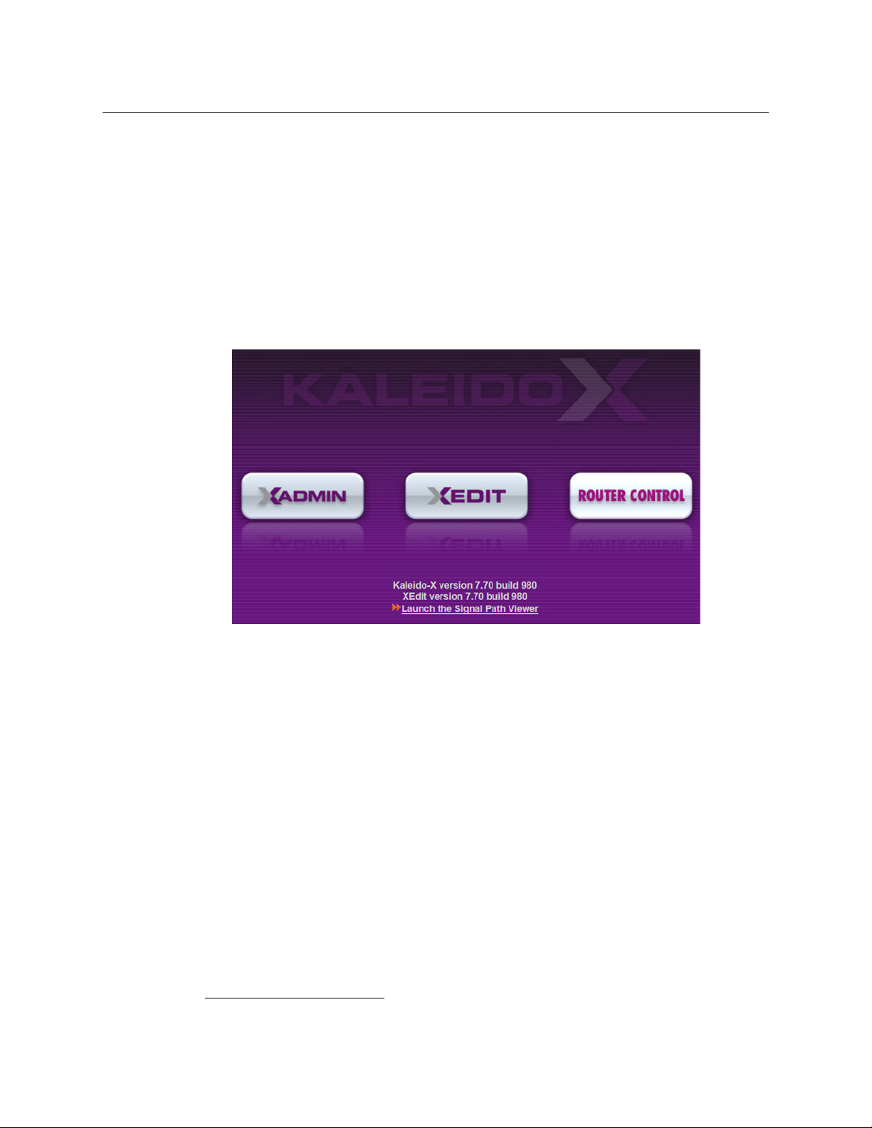
1 From a workstation on the same subnet as the multiviewer, open a Web browser
window and type the multiviewer’s IP address in the address bar.
The multiviewer’s home page appears.
2Click the XEdit button.
The browser prompts you to save an executable file to your hard drive (Kaleido-
windows32-online.exe
2
). This file is an online installer, which will download XEdit and
other companion elements from your multiviewer, and install them. Some browsers
may allow you to run the file directly. Depending on your browser’s security features,
warnings may appear, which you may safely dismiss.
3 Unless your browser let you run the file (and you chose to do so), navigate to the
location were you saved the installer file and open it.
More security warnings or prompts may appear, which you may safely dismiss or
accept.
A window appears, showing the download and installation progress.
2.Installers for Linux or Mac OS X are not yet available.
18
Page 25

KMV-3901/3911
Quick Start Guide
At the end of the installation process:
• If you have Windows 7, or Windows XP, shortcuts ( ) are added to your desktop
and to the Start menu (under All Programs).
• If you have Windows 8.1, or Windows 8, XEdit will appear on your desktop, in the
Apps view with all the other applications on your PC (Windows
screen (Windows
8).
8.1), or in your Start
Once the installation has completed, the XEdit startup screen appears.
19
Page 26

Setting Up Your KMV-3901/3911 Multiviewer
XEdit Installation
Depending on your Windows Firewall settings, a security alert may appear.
•Click Allow access to unblock the application.
If XEdit cannot find all of the fonts it needs already on your PC or laptop, it downloads
them from the multiviewer automatically, in which case a message will appear to
confirm the font update, and instruct you to restart the application.
20
•Click OK to continue, and then open XEdit again, by using the shortcut on your
desktop, in your Apps view (Windows
8.1) or Start screen (Windows 8), or from the
Start menu (Windows 7, Windows XP).
4 When prompted to specify a database, choose one from the Path list, or click Browse to
navigate to the database you wish to use as your local workspace, and then click OK.
Once the database has completed loading, XEdit’s main application window appears.
Page 27

KMV-3901/3911
Quick Start Guide
Note: Once it has been installed from the multiviewer, XEdit remains on
your PC or laptop, and can be launched from the
to your desktop, Apps view, or Start screen (see page 19), or from the Start
menu. Whenever you install a new version of the Kaleido-X software on the
multiviewer, the next time you open XEdit, your installed copy of the
application will be automatically updated from the multiviewer.
shortcut that was added
For more information about calibrating your system, configuring rooms, creating layouts,
and operating the monitor wall, refer to the Kaleido-X User’s Manual, available on the DVD
that shipped with your system, and from the Documentation Library section of Grass
Valley’s website.
21
Page 28

Page 29

Grass Valley Technical Support
For technical assistance, contact our international support center, at
1-800-547-8949 (US and Canada) or +1 530 478 4148.
To obtain a local phone number for the support center nearest you, please consult the
Contact Us section of Grass Valley’s website (
An online form for e-mail contact is also available from the website.
Corporate Head Office
Grass Valley
3499 Douglas-B.-Floreani
St-Laurent, Quebec H4S 2C6
Canada
Telephone: +1 514 333 1772
Fax: +1 514 333 9828
www.grassvalley.com
Contact Us
www.grassvalley.com).
 Loading...