

Page 1
KMV-3901/KMV-3911
HIGH QUALITY, ULTRA-FLEXIBLE AND SCALABLE
MULTIVIEWER
Guide to Installation and Operation
M866-9900-116
2015-04-02
Page 2

Notices
Copyright & Trademark Notice
Copyright © 2010–2015, Grass Valley USA, LLC. All rights reserved.
Belden, Belden Sending All The Right Signals, and the Belden logo are trademarks or
registered trademarks of Belden Inc. or its affiliated companies in the United States and
other jurisdictions. Grass Valley, KMV-3911, KMV-3901, Kaleido-X, iControl, and Densité are
trademarks or registered trademarks of Grass Valley USA, LLC. Belden Inc., Grass Valley USA,
LLC, and other parties may also have trademark rights in other terms used herein.
Terms and Conditions
Please read the following terms and conditions carefully. By using Kaleido multiviewer
documentation, you agree to the following terms and conditions.
Grass Valley hereby grants permission and license to owners of Kaleido multiviewers to use
their product manuals for their own internal business use. Manuals for Grass Valley
products may not be reproduced or transmitted in any form or by any means, electronic or
mechanical, including photocopying and recording, for any purpose unless specifically
authorized in writing by Grass Valley.
A Grass Valley manual may have been revised to reflect changes made to the product
during its manufacturing life. Thus, different versions of a manual may exist for any given
product. Care should be taken to ensure that one obtains the proper manual version for a
specific product serial number.
Information in this document is subject to change without notice and does not represent a
commitment on the part of Grass Valley.
Warranty information is available in the Support section of the Grass Valley Web site
(www.grassvalley.com).
The SDHC Logo is a trademark of SD-3C, LLC.
Title KMV-3901/KMV-3911 Guide to Installation and Operation
Part Number M866-9900-116
Revision 2015-04-02, 10:41
ii
Page 3
Electrostatic Discharge (ESD) Protection
Electrostatic discharge occurs when electronic components are improperly
handled and can result in intermittent failure or complete damage adversely
affecting an electrical circuit. When you remove and replace any card from a frame
always follow ESD-prevention procedures:
• Ensure that the frame is electrically connected to earth ground through the power cord
or any other means if available.
• Wear an ESD wrist strap ensuring that it makes good skin contact. Connect the
grounding clip to an unpainted surface of the chassis frame to safely ground unwanted
ESD voltages. If no wrist strap is available, ground yourself by touching the unpainted
metal part of the chassis.
• For safety, periodically check the resistance value of the antistatic strap, which should
be between
• When temporarily storing a card make sure it is placed in an ESD bag.
• Cards in an earth grounded metal frame or casing do not require any special ESD
protection.
1 and 10 megohms.
KMV-3901/KMV-3911
Guide to Installation and Operation
Protection contre les décharges électrostatiques (DES)
Une décharge électrostatique peut se produire lorsque des composants
électroniques ne sont pas manipulés de manière adéquate, ce qui peut entraîner
des défaillances intermittentes ou endommager irrémédiablement un circuit
électrique. Au moment de remplacer une carte dans un châssis, prenez toujours les
mesures de protection antistatique appropriées
• Assurez-vous que le châssis est relié électriquement à la terre par le cordon
d'alimentation ou tout autre moyen disponible.
• Portez un bracelet antistatique et assurez-vous qu'il est bien en contact avec la peau.
Connectez la pince de masse à une surface non peinte du châssis pour détourner à la
terre toute tension électrostatique indésirable. En l’absence de bracelet antistatique,
déchargez l’électricité statique de votre corps en touchant une surface métallique non
peinte du châssis.
• Pour plus de sécurité, vérifiez périodiquement la valeur de résistance du bracelet
antistatique. Elle doit se situer entre 1 et 10
• Si vous devez mettre une carte de côté, assurez-vous de la ranger dans un sac
protecteur antistatique.
• Les cartes qui sont reliées à un châssis ou boîtier métallique mis à la terre ne
nécessitent pas de protection antistatique spéciale.
:
mégohms.
Recycling
Visit www.grassvalley.com for recycling information.
iii
Page 4
Notices
Electromagnetic Compatibility
This equipment has been tested for verification of compliance with FCC Part 15,
Subpart B requirements for class A digital devices.
Note: This equipment has been tested and found to comply with the
limits for a Class A digital device, pursuant to part 15 of the FCC Rules.
These limits are designed to provide reasonable protection against
harmful interference when the equipment is operated in a commercial
environment. This equipment generates, uses, and can radiate radio
frequency energy and, if not installed and used in accordance with the
instruction manual, may cause harmful interference to radio
communications. Operation of this equipment in a residential area is
likely to cause harmful interference in which case the user will be
required to correct the interference at his own expense.
This equipment has been tested and found to comply with the requirements of the
EMC directive 2004/108/CE:
• EN 55022 Class A radiated and conducted emissions
• EN 61000-3-2 Limits for harmonic current emissions
• EN 61000-3-3 Limitation of voltage changes, voltage fluctuations and flicker
• EN 61000-4-2 Electrostatic discharge immunity
• EN 61000-4-3 Radiated, radio-frequency, electromagnetic field immunity
• EN 61000-4-4 Electrical fast transient/burst immunity
• EN 61000-4-5 Surge transient immunity
• EN 61000-4-6 Conducted disturbances immunity
• EN 61000-4-8 Power frequency magnetic field immunity
• EN 61000-4-11 Voltage dips, short interruptions and voltage variations
immunity
iv
Page 5

Table of Contents
1 Installation . . . . . . . . . . . . . . . . . . . . . . . . . . . . . . . . . . . . . . . . . . . . 1
Features . . . . . . . . . . . . . . . . . . . . . . . . . . . . . . . . . . . . . . . . . . . . . . . . . . . . . . . . . . . . . . . . . . . . . . . . . . 1
Block Diagram . . . . . . . . . . . . . . . . . . . . . . . . . . . . . . . . . . . . . . . . . . . . . . . . . . . . . . . . . . . . . . . . . . . . 2
Front Card-Edge Interface . . . . . . . . . . . . . . . . . . . . . . . . . . . . . . . . . . . . . . . . . . . . . . . . . . . . . . . . . 2
Unpacking . . . . . . . . . . . . . . . . . . . . . . . . . . . . . . . . . . . . . . . . . . . . . . . . . . . . . . . . . . . . . . . . . . . . . . . . 3
Installation in the Densité Frame. . . . . . . . . . . . . . . . . . . . . . . . . . . . . . . . . . . . . . . . . . . . . . . . . . . 3
Rear Connector Panel . . . . . . . . . . . . . . . . . . . . . . . . . . . . . . . . . . . . . . . . . . . . . . . . . . . . . . . . . . . . . 4
Front Card Edge. . . . . . . . . . . . . . . . . . . . . . . . . . . . . . . . . . . . . . . . . . . . . . . . . . . . . . . . . . . . . . . . . . . 6
2 Operation. . . . . . . . . . . . . . . . . . . . . . . . . . . . . . . . . . . . . . . . . . . . . . 9
Card-Edge LEDs . . . . . . . . . . . . . . . . . . . . . . . . . . . . . . . . . . . . . . . . . . . . . . . . . . . . . . . . . . . . . . . . . . . 9
Using the Densité Frame Control Panel . . . . . . . . . . . . . . . . . . . . . . . . . . . . . . . . . . . . . . . . . . . 11
Remote Control Using iControl . . . . . . . . . . . . . . . . . . . . . . . . . . . . . . . . . . . . . . . . . . . . . . . . . . . 13
3 Specifications . . . . . . . . . . . . . . . . . . . . . . . . . . . . . . . . . . . . . . . . . 25
Video Inputs . . . . . . . . . . . . . . . . . . . . . . . . . . . . . . . . . . . . . . . . . . . . . . . . . . . . . . . . . . . . . . . . . . . . . 25
Mosaic Outputs . . . . . . . . . . . . . . . . . . . . . . . . . . . . . . . . . . . . . . . . . . . . . . . . . . . . . . . . . . . . . . . . . . 26
Reference. . . . . . . . . . . . . . . . . . . . . . . . . . . . . . . . . . . . . . . . . . . . . . . . . . . . . . . . . . . . . . . . . . . . . . . . 27
GPI I/O. . . . . . . . . . . . . . . . . . . . . . . . . . . . . . . . . . . . . . . . . . . . . . . . . . . . . . . . . . . . . . . . . . . . . . . . . . . 27
Communication. . . . . . . . . . . . . . . . . . . . . . . . . . . . . . . . . . . . . . . . . . . . . . . . . . . . . . . . . . . . . . . . . . 28
Video Processing Performance . . . . . . . . . . . . . . . . . . . . . . . . . . . . . . . . . . . . . . . . . . . . . . . . . . . 28
Audio Processing Performance . . . . . . . . . . . . . . . . . . . . . . . . . . . . . . . . . . . . . . . . . . . . . . . . . . . 28
Electrical. . . . . . . . . . . . . . . . . . . . . . . . . . . . . . . . . . . . . . . . . . . . . . . . . . . . . . . . . . . . . . . . . . . . . . . . . 28
Appendix A KMV-3901/3911 Local Control Panel . . . . . . . . . . . 29
Contact Us . . . . . . . . . . . . . . . . . . . . . . . . . . . . . . . . . . . . . . . . . . . . . . . 31
1
Page 6

Page 7

Features
Installation
Kaleido-Modular is the most space and energy efficient multiviewer system, with up to
multiviewer outputs per 3RU frame, consuming only 300 Watts in total. It also offers
20
super silent operation, outstanding picture quality, and expansion up to 288
outputs when connected to an upstream router.
The KMV-3911 multiviewer card is the central building block of the Kaleido-Modular
system. It has replaced the earlier KMV-3901 models. Kaleido-Modular systems are available
in the following sizes: 4
× 1 and 24 × 2. In addition to the earlier model’s features, the KMV-3911 supports up to
24
two HD-SDI monitoring outputs.
UNMATCHED SPACE EFFICIENCY
• 20 quad-splits, or ten 8-input KMV-3901/3911 multiviewer cards, per 3RU frame
• Fully loaded frame with 10 cards weighs only 9.9 kg (21.8 lbs)
LOW POWER CONSUMPTION
• 300 Watts for fully loaded 3RU frame with 10 cards and up to 20 outputs
• 24 Watts per dual-output card
× 1, 4 × 2, 8 × 1, 8 × 2, 12 × 1, 12 × 2, 16 × 1, 16 × 2, 20 × 1, 20 × 2,
multiviewer
SUPER SILENT
• Ideal for installation within studios, control rooms and trucks
HIGH QUALITY, FLEXIBLE MONITORING
• Outstanding multiviewer picture quality, based on award-winning Kaleido technology,
with all essential display elements for production
• Choice of single multiviewer output per card with up to 8 pictures, or dual quad-split
displays
• The KMV-3911 supports up to two HD-SDI monitoring outputs (one associated with
1, and one with Head 2 if enabled), with embedded audio
Head
ROUTER INTEGRATION
• Tight integration with NVISION and third party routers allows expansion up to
inputs and 288 multiviewer outputs
1152
• Multiple multiviewer outputs can be controlled from a single panel
ULTRA-RESILIENT
• Hot-swappable cards with Auto-Recovery for configuring cold replacement cards
during maintenance
• 3RU frame features dual hot-swappable power supplies and fans plus redundant
Ethernet
1
Page 8
Installation
Block Diagram
3Gbps/HD/SD OPERATION
• Triple-rate, future-proof performance
MIX AND MATCH CARD FUNCTIONS
• Kaleido-Modular multiviewer cards can be installed in a 3RU frame with other Densité
Series cards, such as signal processors and DAs, for maximum space and costeffectiveness
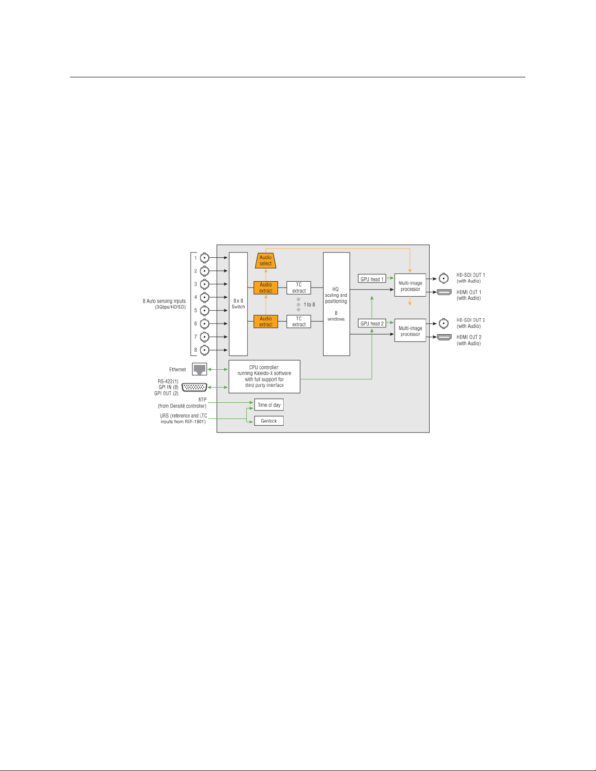
Block Diagram
The following block diagram shows the functionality of the KMV-3911. Except for the HDSDI monitoring outputs, the same diagram applies to the earlier KMV-3901 models.
Functional block diagram of the KMV-3911
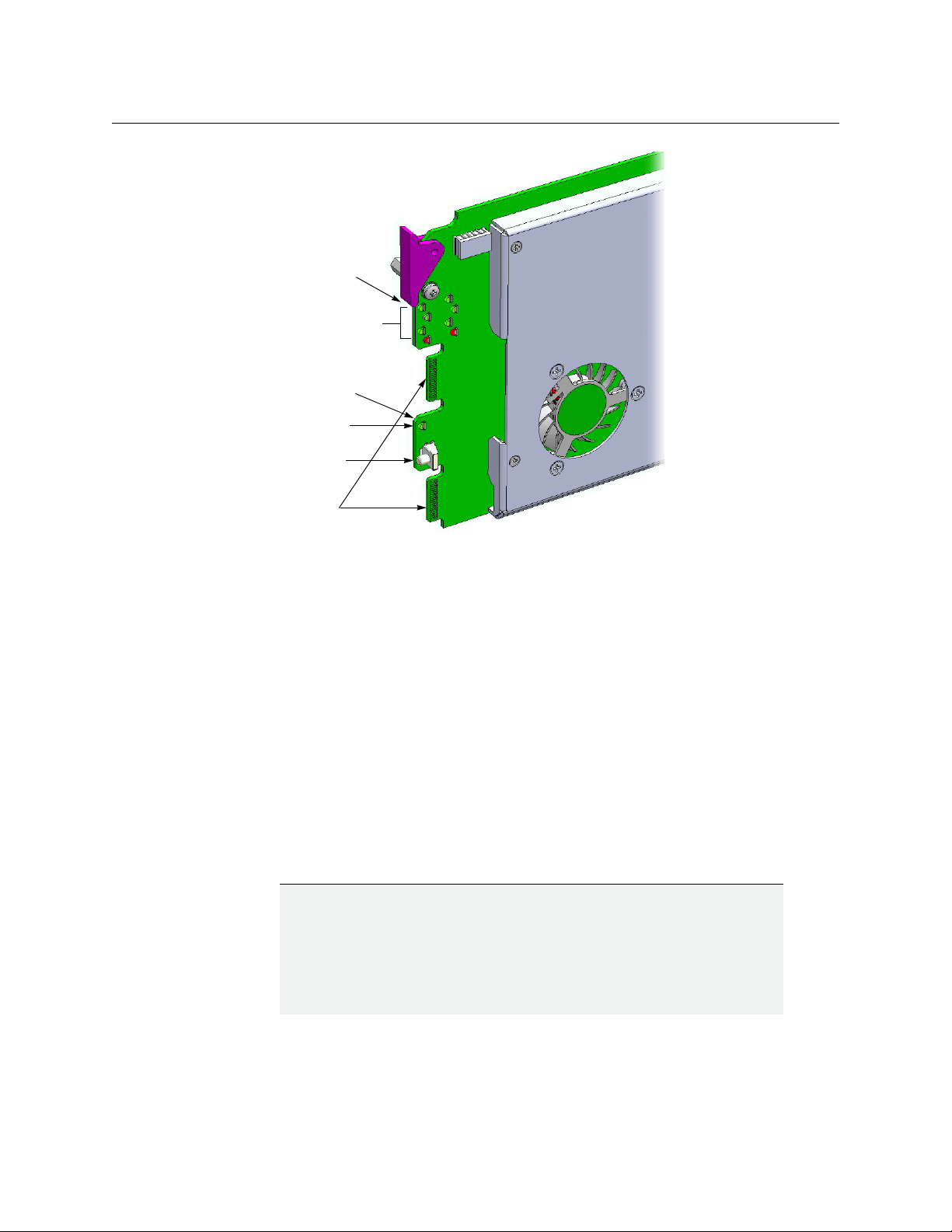
Front Card-Edge Interface
The front card-edge of the KMV-3901/3911 incorporates several operational elements:
• Select Button (see Using the Densité Frame Control Panel, on page 11)
• Status LED (see Status LED, on page 10)
• CPU Status LED (see CPU Status LED, on page 10)
•Boot LED (see Boot LED, on page 10)
•Power LED (see Power LED, on page 11)
• SDI LEDs (8) (see SDI LEDs, on page 11)
• USB connector (see USB Connector, on page 6)
• Bridge connectors (2) (see Bridge Connectors, on page 7)
2
Page 9
KMV-3901/KMV-3911
Bridge connectors
Select button
Status LED
Boot LED, Power LED
& CPU Status LED
(other side of board)
SDI LEDs
USB connector
(other side of board)
Guide to Installation and Operation
Unpacking
Installation in the Densité Frame
Front card-edge layout
Make sure the following items have been shipped with your KMV-3901/3911. If any of the
following items are missing, contact your distributor or Grass Valley.
• KMV-3911 or KMV-3901 3Gbps/HD/SD multiviewer card
• the appropriate rear connector panel for the card (see KMV-3911-8X2-3DRP rear panel,
or KMV-3901-8X2-3DRP rear panel, on page 5)
The KMV-3901/3911 and its associated rear connector panel must be mounted in a Densité
3 frame or a Densité 3 mini frame. It is not necessary to switch off the frame’s power when
installing or removing the card. Refer to the Densité 3 frame manual or the Densité 3 mini
frame manual for detailed instructions on installing cards and their associated rear panels.
IMPORTANT
Keep the KMV-3901/3911 offline at initial setup to avoid conflicts.
Before powering up the Densité housing frame, make sure none of the KMV3901/3911multiviewer cards it contains are connected to the network, to
avoid IP-address conflicts during initial physical setup
is no cable connected to your cards’ ETH port.
— i.e. make sure there
3
Page 10
Installation
Rear Connector Panel
IMPORTANT (continued)
Densité CPU-ETH2 Enhanced Ethernet Controller Card
A Densité frame housing a KMV-3901/3911 multiviewer card must have a
controller card (Densité CPU-ETH2 Enhanced Ethernet Controller Card) with
firmware version 2.0.4 or later. A controller with an earlier version of the
firmware cannot provide a time reference to the multiviewer card. Make sure
the controller’s internal clock is set to the correct date and time. The clock
settings will persist for 10 days after a power loss. Should you need to change
the time on a Densité CPU-ETH2 controller, then make sure to restart all
multiviewers located in the same housing frame as the controller card. Refer
to the Densité CPU-ETH2 Enhanced Ethernet Controller Card Guide to
Installation and Operation for more information.
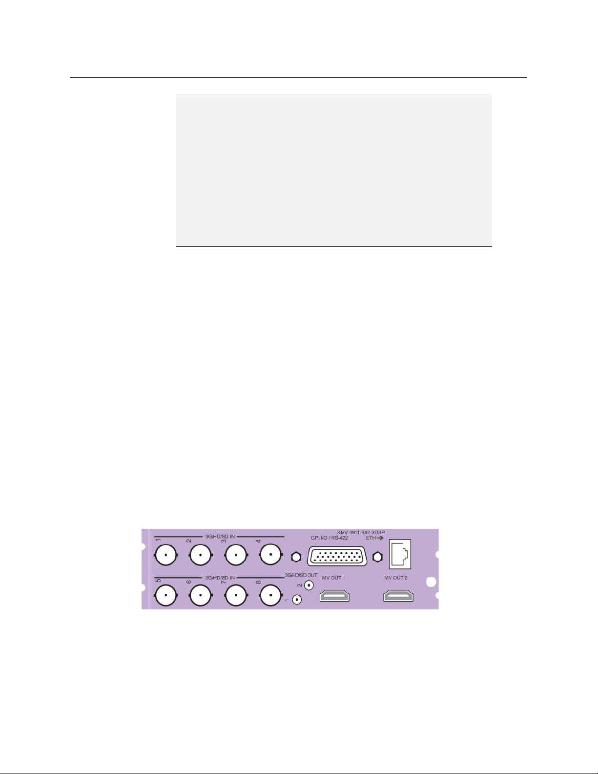
Rear Connector Panel
The KMV-3901/3911 requires a dual-slot-width rear panel:
• Eight 3G/HD/SD inputs (BNC connectors). Optional inputs 5-8 are available only in the
case of 8 × 2, and 8 × 1 models.
• Two 3G/HD/SD multiviewer outputs (HDMI connectors). Optional MV OUT 2 is available
only in the case of 4 × 2, 8 × 2 cards.
• Two HD-SDI monitoring outputs (DIN 1.0/2.3 connectors). Only supported with the
KMV-3911 models.
• One DB-26 connector for GPI I/O lines (8 in / 2 out) and RS-422 control. Grass Valley’s
NSH26M wiring terminal adapter can be used to connect the GPI lines to this
connector.
• One RJ-45 for data transfer over Ethernet.
With the double-width rear panel installed in a Densité-3 frame, the KMV-3901/3911 must
be installed in the rightmost of the two slots covered by the panel in order to mate with the
panel’s connectors.
In a Densité 3 mini frame, the card must be placed in the bottom slot.
If it is placed in the wrong slot, the front panel LED will flash red. Move the card to the other
slot for correct operation. No damage will result to the card if this occurs.
KMV-3911-8X2-3DRP rear panel
4
Page 11
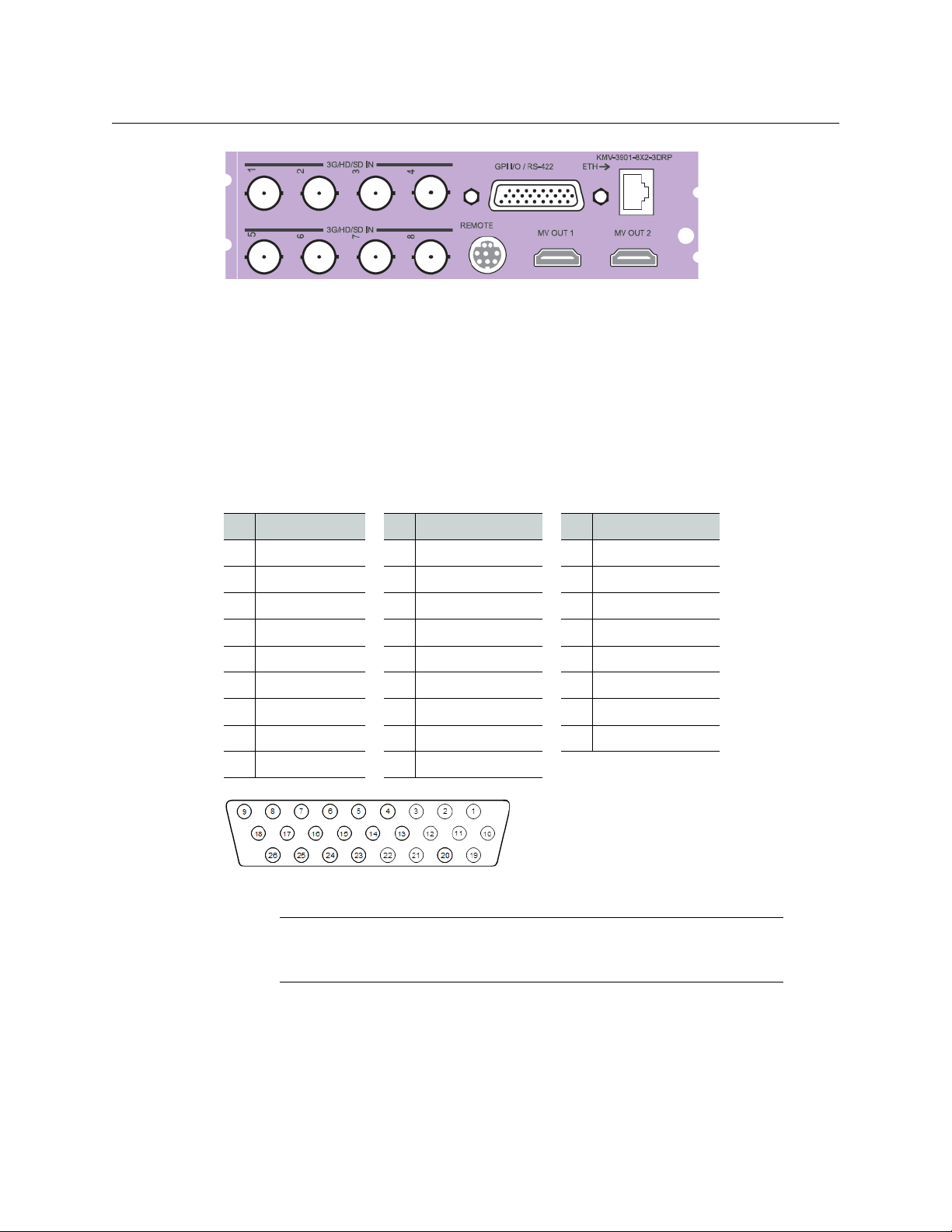
KMV-3901-8X2-3DRP rear panel
Ethernet Port
The Ethernet port must be configured before it can be used to communicate with the KMV3901/3911. See
GPI/RS-422 Connector
The DB-26 GPI connector carries 8 GPI IN and 2 GPI OUT lines, plus the RS-422 interface. The
pinout of this connector is listed below.
:
Pin Function Pin Function Pin Function
1 422 TX+ 10 422 TX - 19 GND
2 422 RX+ 11 422 RX - 20 GND
KMV-3901/KMV-3911
Guide to Installation and Operation
Network Settings Panel, on page 16.
3 GPI IN2 12 GPI IN1 21 GPI IN3
4 GND 13 GPI IN4 22 GPI IN5
5 GPI IN7 14 GPI IN6 23 GPI IN8
6 NC 15 GND 24 NC
7 OUT 1-(emitter) 16 GND 25 OUT 1+ (collector)
8 GND 17 GND 26 OUT 2- (emitter)
9 NC 18 OUT 2+ (collector)
DB-26 GPI/RS-422 connector
Note: Grass Valley’s NSH26M wiring terminal adapter can be used to
connect the GPI and RS-422 lines to this connector. The NSH26M comes with
a label that identifies the pinout to make wiring easy.
HDMI Mosaic Output Connectors
Connect these outputs (MV OUT 1 and MV OUT 2) to video displays using HDMI cables.
5
Page 12
Installation
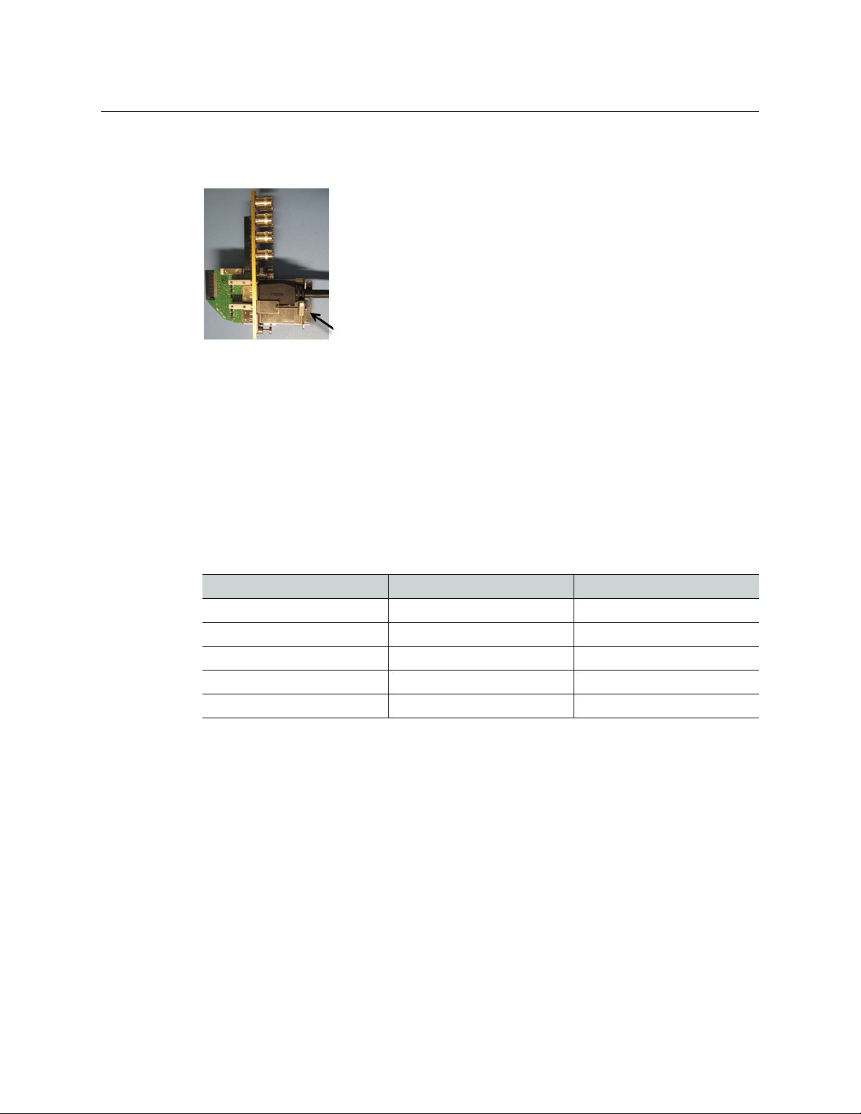
Incorporated locking mechanism
Front Card Edge
Space constraints on the KMV-3901/3911 rear module do not allow HDMI connectors with a
screw securing mechanism. For this reason, a special locking mechanism is incorporated on
the rear panel. The mechanism is adjustable for many sizes of cables and shells.
In the case of a KMV-3901/3911 with both heads activated, the two HDMI cables should
have same-size plug connectors; otherwise the locking mechanism will not hold the
smaller connector securely. If your cables have long plug connectors that will not fit the
special locking mechanism, you can secure them with a cable wrap threaded through the
hole in the bracket.
HD-SDI Monitoring Output Connectors
There are two HD-SDI monitoring outputs: one associated with Head 1, and one with
2 if enabled. The HD-SDI output resolution depends on the current resolution at the
Head
corresponding HDMI output, and, in the case of a 1080-line resolution, on the scan format
(interlaced, progressive) configured in XEdit for this output head.
HDMI output resolution HD-SDI output (interlaced) HD-SDI output (progressive)
1280 × 720 50 Hz No output 720p 50 Hz
1280 × 720 59.94 Hz No output 720p 59.94 Hz
1920 × 1080 50 Hz 1080i 50 Hz 1080p 50 Hz
1920 × 1080 59.94 Hz 1080i 59.94 Hz 1080p 59.94 Hz
Any other HDMI resolutions No output No output
Front Card Edge
USB Connector
This USB connector is accessible when the front panel of the Densité frame is open. The USB
connector is used for the following tasks:
• Upgrading the Kaleido-X Software and KMV-3901/3911 firmware, by using a USB key
prepared with the appropriate upgrade package. Refer to the Kaleido-X Release Notes
for details.
• Controlling some features on the monitor wall, by using a mouse (e.g. showing or
hiding the monitor wall dashboard, dismissing the confirmation message that appears
6
Page 13

at the end of the upgrade process). Refer to the Kaleido-X User’s Manual for details.
Bridge Connectors
The bridge connectors are accessible when the front panel of the Densité frame is open.
They are used to interconnect two adjacent KMV-3901/3911 cards by using a cascade
bridge (Grass Valley part no. KMV-3901-8XN-BRIDGE). Refer to the KMV-3901/3911 Cascade
Step-by-Step Configuration guide, available on the Kaleido-X DVD, for detailed instructions
on setting up a cascade system.
KMV-3901/KMV-3911
Guide to Installation and Operation
Note: The KMV-3901/3911 does not support USB hubs. Only one USB
device (USB key or mouse) can be connected at a time. If an externally
powered USB hub is connected to the KMV-3901/3911, then a mouse
connected to the hub will not work.
7
Page 14

Page 15

Operation
Select button
Status LED
SDI LEDs
2
1
3
4
5
6
7
8
CPU Status LED
Power LED
Boot LED
The KMV-3901/3911 can be controlled in different ways:
• On the Densité frame, the local control panel and its buttons can be used to navigate
menus and adjust parameter values (see
page 11).
• Grass Valley’s iControl system can be used to access the card’s operating parameters
from a remote computer, using a convenient graphical user interface (see
Control Using iControl, on page 13).
• The loading and management of layouts is handled via a Java-based application, XEdit,
accessed through a dedicated Ethernet port (see the Kaleido-X User’s Manual,
(available on the Kaleido-X DVD that shipped with your system, and from the Grass
Valley support portal).
• A GPI interface allows remote layout selection.
• The output resolution of the card can be controlled automatically through the EDID
interface with the display.
• The RCP-200 advanced remote control panel, and the Kaleido-RCP2 control panel allow
you to perform operations on the monitor wall, either by themselves or in association
with an external keyboard and a mouse. Refer to the RCP-200, Kaleido-RCP2, and
Kaleido-X documentation (available on the Kaleido-X DVD that shipped with your
system).
Using the Densité Frame Control Panel, on
Remote
Card-Edge LEDs
9
Page 16

Operation
Card-Edge LEDs
Status LED
The Status LED is located on the front card-edge of the KMV-3901/3911, immediately above
the Select button, and is visible through the front access door of the Densité frame. This
multi-color LED indicates the status of the KMV-3901/3911 by color, and by blinking/steady
illumination:
LED Meaning
Green Normal
Blinking orange Booting (or the card is selected for local control)
Red No Ethernet / SD card error
Blinking red Fan failure / no rear / duplicate IP address
The Status LED always shows the most severe detected error status that it is configured to
display (see
Alarm Configuration Panel, on page 17), and in the table above error severity
increases from top to bottom, with green representing no error/disabled, and blinking red
the most severe error.
If the Status LED is blinking orange, it means that the card is selected for local control using
the Densité frame’s control panel, or that the card is booting up. See
Using the Densité
Frame Control Panel, on page 11 for details.
CPU Status LED
Monitors the status of the CPU operation.
LED Meaning
Green OK
Red CPU kernel error
Blinking red Upgrading
Boot LED
Monitors the status of the system firmware.
LED Meaning
Blinking green System OK (heartbeat signal)
Steady red Beginning of start-up process (normal)
Steady green
or OFF
Continuous - error
Software not running
10
Page 17

Power LED
SDI LEDs
KMV-3901/KMV-3911
Guide to Installation and Operation
Monitors the status of the power on board the KMV-3901/3911 card.
LED Meaning
Green OK
Red Error detected
This is a latched error and will remain displayed until the next reboot, even
if the error was a brief glitch and the supply is OK.
If the LED remains red after a restart, there is or has been a fault in the
power source.
This group of eight LEDs monitors the status of the eight inputs to the KMV-3901/3911 card.
The frame door must be open for the LEDs to be visible.
LED Meaning
Green Input SDI signal detected
Red Error - no input signal detected
Using the Densité Frame Control Panel
All of the cards installed in a Densité frame are connected to the frame’s controller card,
which handles all interaction between the cards and the outside world. There are no
operating controls located on the cards themselves. The controller supports remote
operation via its Ethernet ports, and local operation using its integrated control panel.
The local control panel is fastened to the controller card, and consists of a display unit
capable of displaying two lines of text, each 16
Densité CPU-ETH2 local control panel
The panel is assigned to operate any card in the frame by pressing the Select button on the
front edge of that card. The Status LED on the selected card will then be blinking orange.
Press the CONTROLLER button on the control panel to select the controller card itself.
characters in length, and five buttons.
11
Page 18

Operation
Navigating the Local Control Panel Menu
Navigating the Local Control Panel Menu
The KMV-3901/3911 has operating parameters which may be adjusted locally at the
controller card interface. Press the Select button on the KMV-3901/3911 front card edge (see
Front Card-Edge Interface, on page 2) to assign the local control panel to operate the card.
Use the control panel buttons to navigate through the menu, as described below.
The complete menu structure is shown in Appendix A KMV-3901/3911 Local Control Panel,
on page 29.
The local control panel displays a menu that can be navigated using the four buttons
located next to the display. The functionality of the buttons is as follows:
[+] and [-] Used for menu navigation and value modification.
SEL Gives access to the next menu level. When a parameter value is shown, pressing this
button once enables modification of the value using the [+] and [-] buttons;
pressing a second time confirms the new value.
ESC Cancels the effect of parameter value changes that have not been confirmed;
pressing ESC causes the parameter to revert to its former value.
Pressing ESC moves the user back up to the previous menu level. At the main menu,
ESC does not exit the menu system. To exit, press the Select button on the front
edge of the card being controlled.
If no controls are operated for 30 seconds, the controller reverts to its normal standby
status, and the selected card’s Status LED reverts to its normal operating mode. If a
parameter was changed on the card but not submitted (SEL was not pressed) and the 30
second timeout occurs, the parameters will be confirmed as if the SEL button had been
pressed.
Saving a Restore Point to the Controller’s Non-Volatile Memory
The Densité CPU-ETH2 controller can be configured to automatically apply parameters
from a previously saved restore point, when you replace a card with another card of the
same type. In the case of a KMV-3901/3911 card the restore point includes the multiviewer’s
system name and networking parameters.
To save a restore point to the controller’s non-volatile memory, proceed as follows:
1 On the Densité frame’s local control panel, press the CONTROLLER button.
2 Press the [-] button repeatedly until RESTORE POINTS appears on the display, and then
press the SEL button.
3 Press the [-] button repeatedly until SAVE A CARD appears on the display, and then
press the SEL button.
4 Press the [-] button repeatedly until CARD # N-where N matches the slot number for the
Kaleido-Modular card whose configuration you wish to save-appears on the display,
and then press the SEL button.
12
Page 19

Remote Control Using iControl
Click to hide
or show the
navigation
area
Navigation area
Status icon
area
Operating
control
area
The KMV-3901/3911 may be controlled by using Grass Valley’s iControl version 3.60 or later.
This section describes the control panel associated with the KMV-3901/3911 and its use.
Refer to the iControl User’s Guide for information about setting up and operating iControl.
In iControl Navigator or iControl Web, double-click a KMV-3901/3911 icon to open the
associated control panel.
KMV-3901/3911 Service Control Panel in iControl
The card type (KMV-3901 in this example) and the slot number where the card is installed in
the Densité frame are indicated in the window’s title bar. There are three main areas in the
KMV-3901/3911 control panel window itself: the status icon area, the navigation area, and
the operating control area.
KMV-3901/KMV-3911
Guide to Installation and Operation
13
Page 20

Operation
Message area
KMV-3901/3911 Service Control Panel in iControl
The status icon area shows a series of twelve icons that report the status of some card
parameters.
Icon 1 - Control status Icon 2 - Reference
status
Green: Remote
control via
iControl
Green: Locked to
frame reference
(mouse over to
see format)
Icons 3 to 10 - Status
of inputs 1 to 8
Green: Input
signal detected
(mouse over to
see details of the
Icons 11 and 12 - Status
of outputs 1 and 2
Green: EDID
information
detected on the
HDMI channel
format)
Yellow: Local
control at the
Densité frame
using the menu
Red: Unavailable
Red: No input
signal detected
Red: No EDID
information
detected on the
HDMI channel
Move the mouse over an icon and a status message appears below the icon area providing
additional information.
Error status messages appear in the message area without mouse-over.
14
• If there are multiple errors, the error messages cycle so all can be seen.
• The icon whose status or error message is shown is highlighted with a mauve
background.
The navigation area contains buttons that control the contents of the main area. Click a
button to access the associated features. Click the left side border (identified by a small
arrow icon) to hide or reveal this area.
The operating control area contains the main operating controls for managing the KMV3901/3911 multiviewer’s feature set. The contents change depending on the button you
clicked in the navigation area. The five panels are described individually in the following
sections:
• Layout Controls Panel below
• Output Settings Panel, on page 15
• Network Settings Panel, on page 16
• Alarm Configuration Panel, on page 17
Page 21

• Status Panel, on page 20
• Info Panel, on page 21
Layout Controls Panel
The two Layout lists are used to load layouts to the monitor wall displays. Depending on
your configuration, you may have either one room with one or two displays, or two rooms
with one display each. Sample layouts are available on the KMV-3901/3911 multiviewer as
shipped, for immediate use. Additional layouts may be created in XEdit, and exported to
the multiviewer. Refer to the Kaleido-X User’s Manual for more information on creating
rooms and layouts.
KMV-3901/KMV-3911
Guide to Installation and Operation
Output Settings Panel
Set the resolution of the multiviewer output heads to an appropriate value based on the
displays in use. If a display uses EDID (Extended Display Identification Data) to
communicate its characteristics to the KMV-3901/3911 multiviewer via the HDMI
connector, the matching can be done automatically, in which case the detected resolution
appears in the Detected resolution box. Select the check box to use the detected
resolution. If the detected resolution is not used (either because the check box is not
selected or because the display does not make the information available) the value
selected in the Output resolution list will be used.
15
Page 22

Operation
Network Settings Panel
The following table lists some (but not all) output formats supported at the HDMI
connections. You can customize your own timing rates for resolutions ranging from 1280 ×
1024 pixels up to 1920 × 1200 pixels (all progressive scan), by using XEdit.
Resolution Format name Refresh rates (Hz)
1280 × 1024 SXGA 50.00, 59.94
1280 × 1024 BARCO 59.94
1360 × 768 NEC 50.00, 59.94
1480 × 1200 Christie 50.00, 59.94
1600 × 1200 UXGA 50.00, 59.94
1920 × 1080 Baycat 50.00, 59.94
1920 × 1200 WUXGA 50.00, 59.94
Note: All KMV-3901/3911 cards within a housing frame must have their
output heads configured with the same refresh rate. If your frame is
referenced, then the heads’ refresh rate must also match the reference
signal's refresh rate.
Network Settings Panel
The KMV-3901/3911 is shipped with default network settings, which will not work for your
network and must be changed. You may need to consult your network administrator to get
the correct values. Enter the appropriate IP address, mask and gateway information to
configure this KMV-3901/3911 within your Ethernet network.
16
Page 23

KMV-3901/KMV-3911
Guide to Installation and Operation
Notes
• These settings apply to the rear-panel Ethernet port of the KMV-3901/3911
itself; not to the Ethernet ports at the back of the Densité controller card.
• The MAC Address is a hard-wired attribute of the KMV-3901/3911 card, and
is not configurable; the information is presented here for information only.
Click Apply to set these values into the card, or Cancel to leave the original values
unchanged.
Alarm Configuration Panel
This panel allows the alarm reporting of the KMV-3901/3911 to be configured. When you
click the Alarm config. button, the panel opens as a separate window, which can be resized
if needed.
17
Page 24

Operation
Overall
alarm
indicators
Alarm Configuration Panel
Status/Name
The Status/Name column lists all the alarms reported by this KMV-3901/3911 multiviewer.
Next to each alarm name, an icon shows the alarm’s current status.
Card LED, Overall alarm and GSM contribution
The Card LED, Overall alarm and GSM contribution columns contain lists that allow you to
set the level of contribution of each individual alarm to the alarm named in the column
heading.
Card LED This column allows you to configure the behavior of the KMV-3901/3911’s card-
Overall alarm This column allows you to configure the contribution of each individual alarm
edge status LED.
to the overall alarm associated with this card. Indicators for the overall alarm
appear in the upper left corner of the control panel windows, and at the
bottom of the Status/Name column.
18
GSM
contribution
Note: N/A means the alarm is not user-configurable.
This column allows you to configure the contribution of each individual alarm
to the GSM alarm status associated with this card. The GSM is a dynamic
register of all iControl system alarms, and is also an alarm provider for external
applications. The possible values for the GSM contribution are related to the
overall alarm contribution:
• If the overall alarm contribution is set to Disabled, then the GSM alarm
contribution can be set to any available value.
• If the overall alarm contribution is set to any level other than disabled, then
the GSM contribution follows the overall alarm.
Alternatively, select the Overall alarm and GSM contribution follow card LED
check box, to have the same contribution in all three contexts for the
corresponding individual alarm.
Page 25

The lists may contain some or all of the following options:
KMV-3901/KMV-3911
Guide to Installation and Operation
The alarm makes no contribution (black icon)
The alarm is of minor importance (yellow icon)
The alarm is of major importance (orange icon)
The alarm is of critical importance (red icon)
The alarm exists but has no effect (used for text and composite alarms)
TIP
Click one of the Set all buttons beside a section heading to assign the same
level to all alarms in that section of the column at once.
iControl maintains a log of alarm events associated with the card. The log is useful for
troubleshooting and identifying event sequences. Select the Log events check box to
enable logging of alarm events for an individual alarm.
At the bottom of the window are several other controls.
Overall alarm and GSM contribution follow card LED
Select the check box to force the overall alarm and GSM contribution to be identical to the
Card LED status:
• All Overall alarms for which there is a Card LED alarm will be forced to match the Card
LED alarm.
• All Overall Alarms for which there is no Card LED alarm will be Disabled.
A message prompts you to confirm the action, since it will result in changes to the
configuration window that cannot readily be undone.
Copy to other cards
Click Copy to other cards to open a window that allows the alarm configuration set for this
card to be copied into another KMV-3901/3911 card. Select one or more destination cards
from the list in the window by selecting the corresponding check boxes, or all of them by
selecting the All check box.
19
Page 26

Operation
Status Panel
Get alarm keys
Click Get alarm keys to save a file containing a list of all alarms on this card and their current
values, along with an Alarm Key for each. The alarm keys are useful for system integration
and troubleshooting. The file is saved in CSV format.
Status Panel
OK, Apply, Cancel
•Click OK to accept the settings and close the window once the card confirms that there
are no errors.
•Click Apply to accept the settings, but leave the window open.
•Click Cancel to close the window without applying any changes, and leave the previous
settings intact.
This panel reports on the status of the eight video input ports, with a status icon and text
description of the format for each. Status of each of the eight GPI inputs and two GPI
outputs is also reported, as Open or Closed. System status is reported at the bottom of the
panel:
• Reference: status icon and text description
• FA N: status of the on-card cooling fan
• Software version: text description
20
Page 27

KMV-3901/KMV-3911
Guide to Installation and Operation
Info Panel
When the KMV-3901/3911 is included in an iControl environment, certain information
about the card may be made available to the iControl system. In the boxes with a white
background, you can type labels and comments that will make this card easier to identify in
a complex setup.
21
Page 28

Operation
Info Panel
Label Type a label to identify this KMV-3901/3911 when it appears in iControl
applications.
Short label Type the shorter label that iControl uses in some cases (8 characters).
Source ID Type a descriptive name for this KMV-3901/3911.
Comments Type any desired text.
The remaining boxes show manufacturing information about this card.
22
Page 29

KMV-3901/KMV-3911
Guide to Installation and Operation
Three buttons give access to additional information and controls:
Details Reports the firmware version, service version, and panel version for this card.
Advanced Shows the Long ID for this card. The Long ID is the address of this KMV-
3901/3911 in the iControl network.
Remote system
administration
Opens the Joining Locators window, which lists remote lookup services to
which this KMV-3901/3911 is registered.
•Click Add to force the iControl service for this KMV-3901/3911 to register
itself on a lookup service, by using the following syntax in the Input
window:
jini://<ip_address>
where <ip_address> is the IP address of the server running the lookup
service.
• Select one of the services listed in the window by clicking on it, and then
click Remove to remove it from the list.
23
Page 30

Page 31

Video Inputs
Connector BNC
SD-SDI
Signal SMPTE 259M-C (270 Mbps), SMPTE 272M-1994
Formats 525 and 625
Return loss > 15 dB up to 270 MHz
Jitter < 0.2 UI
Cable length 250 m (820 ft) (Belden 1694A)
HD-SDI
Signal SMPTE 292M-C (1.485, 1.485/1.001 Gbps),
Specifications
SMPTE 272M-1994
Formats 720p24, 720p25, 720p29.97, 720p50, 720p59.94
1080i50, 1080i59.94
1080PsF23.98, 1080PsF24, 1080PsF25, 1080PsF29.97
1080p23.98, 1080p24, 1080p25, 1080p29.97
Note: The Kaleido-X software does not distinguish between
1080PsF25 and 1080i50, and neither between 1080PsF29.97 and
1080i59.94. Both 1080PsF25 and 1080i50 are reported as 1080i50,
and both 1080PsF29.97 and 1080i59.94 are reported as 1080i59.94,
on the monitor wall and in XAdmin’s Status and Options page.
Return loss > 15 dB up to 1.5 GHz
Jitter < 0.2 UI
Cable length 100 m (328 ft) (Belden 1694A)
3G-SDI
Signal SMPTE 424M-2006 (2.97, 2.97/1.001 Gbps)
Formats 1080p50 (level A only)
1080p59.94 (level A only)
Return loss > 10 dB up to 2.97 GHz
25
Page 32

Specifications
Mosaic Outputs
3G-SDI (continued)
Jitter < 0.3 UI
Cable length 100 m (328 ft) (Belden 1694A)
Note: If you wish to use the HD-SDI monitoring outputs (see
page 26) and configure them for a 1080p format, then the
multiviewer supports a maximum cable length of 85 m (279 feet) at
the video inputs. Refer to “Configuring the HD-SDI Monitoring Output
Format” in the “Setting Up Rooms” chapter of the Kaleido-X User's
Manual, for more information.
Graphic converted to HD-SDI from KXI-DVI-Bridge
Signal SMPTE 292M-C (1.485, 1.485/1.001 Gbps)
Formats 1024 × 768 @ 60 (XGA)
1280 × 1024 @ 60 (SXGA)
1366 × 768 or 1368 × 768 @ 60 (WXGA)
1680 × 1050 @ 60 (WSXGA+)
Cable length 100 m (328 ft) (Belden 1694A)
Mosaic Outputs
HDMI outputs (2)
Signal HDMI V1.3
Format 1280 × 1024 up to 1920 × 1200p configurable (all progressive scan)
Cable length 15 feet
Connector HDMI type connector
Signal path 8 bits output
HD-SDI monitoring outputs (2)
Signal 4:2:2 SMPTE 292M-C (1.5 Gbps), SMPTE 424M
Formats 720p50, 720p59.94
1600 × 1200 @ 60 (UXGA)
Supported refresh rates: 50 Hz and 59.94 Hz
Refer to the table on page 16 for a list of supported formats.
1080i50, 1080i59.94
1080p50 (level A only), 1080p59.94 (level A only)
26
Note: If you configure an HD-SDI monitoring output for a 1080p
format (see
length of 85 m (279 feet) at the video inputs. Refer to “Configuring the
HD-SDI Monitoring Output Format” in the “Setting Up Rooms”
chapter of the Kaleido-X User's Manual, for more information.
page 6), then the multiviewer supports a maximum cable
Page 33

Reference
GPI I/O
KMV-3901/KMV-3911
Guide to Installation and Operation
HD-SDI monitoring outputs (2) (continued)
Audio SMPTE 299M (limited to one pair, embedded on group 1, pair 1)
Cable length 100 m (328 feet) for 3G or HD, 256 m (840 feet) for SD (Belden 1694A)
Alignment jitter
(100 KHz)
Connector DIN 1.0/2.3
Internal Universal Reference from the Densité frame
< 0.2 UI
Note: If your housing frame is referenced, then all KMV-3901/3911
cards within the frame must have their output heads configured with
a refresh rate that matches the reference signal’s refresh rate.
GPI inputs (8)
Description Contact closure to GND
Pull-up voltage 3.3 Volts
Source current 30 μA when input shorted
Low-level activation 0.8 Volts max
Over voltage 24 Volts max
Connector Terminal block interface PCB via DB-26
GPI outputs (2)
Description Contact closure to GND
Signal Open collector 5 to 12 VDC
Contact closure current 50 mA max
Reverse voltage -15 Volts max
Reverse current -50 mA max
V out low 0.6 Volts at 1.5mA
Connector Terminal block interface PCB via DB-26
27
Page 34

Specifications
Communication
Communication
Ethernet (1)
Connector RJ-45
Serial port (1)
Signal RS-422 (SMPTE 207M, EBU-3245)
Connector Terminal block interface PCB via DB-26
Video Processing Performance
Signal path 8-bit YCbCr to 24-bit RGB
Processing delay ~ 1 field in genlock mode; 1 - 2 fields in non-genlock mode
Audio Processing Performance
Electrical
Quantization 20-24 bits
Sampling 48 kHz
THD+N 80 dB
SNR 98 dB
Power consumption 24W max
28
Page 35

KMV-3901/3911 Local Control Panel
KMV-3901/3911 user interface (local menu structure)
INPUT STATUS 1 {FORMAT}**
2 {FORMAT}**
3 {FORMAT}**
4 {FORMAT}**
5 {FORMAT}**
6 {FORMAT}**
7 {FORMAT}**
8 {FORMAT}**
{CARD VERSION}**
RESOLUTION HEAD1 {List of resolutions;* = current}**
HEAD2 {List of resolutions;* = current}**
{LINK STATE}**
GPIO STATUS GPI INPUTS LINE 1 {STATE}**
LINE 2 {STATE}**
LINE 3 {STATE}**
LINE 4 {STATE}**
LINE 5 {STATE}**
LINE 6 {STATE}**
LINE 7 {STATE}**
LINE 8 {STATE}**
GPI OUTPUTS LINE 1 {STATE}**
LINE 2 {STATE}**
{FAN STATUS}**
NETWORK SETTINGS IP ADDRESS EDIT ###.###.###.###
NETMASK EDIT ###.###.###.###
DEFAULT GW EDIT ###.###.###.###
{MAC ADDRESS}**
* All KMV-3901/3911 cards within a housing frame must have their output heads configured with the same
refresh rate. If your frame is referenced, then the heads’ refresh rate must also match the reference signal's
refresh rate.
** Parameters shown here in braces { } will display the actual value of the item and not the text shown above.
29
Page 36

Page 37

Grass Valley Technical Support
For technical assistance, contact our international support center, at
1-800-547-8949 (US and Canada) or +1 514 333 1772.
To obtain a local phone number for the support center nearest you, please consult the
Contact Us section of Grass Valley’s Web site (
An online form for e-mail contact is also available from the Web site.
Corporate Head Office
Grass Valley
3499 Douglas-B.-Floreani
St-Laurent, Quebec H4S 2C6
Canada
Telephone: +1 514 333 1772
Fax: +1 514 333 9828
www.grassvalley.com
Contact Us
www.grassvalley.com).
 Loading...